Embed Size (px)
Citation preview
6th National Congress on Civil Engineering, April 26-27, 2011, Semnan University, Semnan, Iran
1
Using NSM Method in R/C Beams Strengthening by FRP Strips
M. S. Karimi1, M. Nasseri2, E. Maroofi2
1. Associated professor, School of Civil Eng., Semnan University, Semnan, Iran. 2. Graduated Student, School of Civil Eng., Semnan University, Semnan, Iran.
(Email: [email protected])
Abstract Reinforced concrete flexural elements may be required to strengthen during their service life due to various reasons, e.g. defect or decay in mechanical materials properties, imperfections on construction, or increasing of design loads due to changing in utilization or rules of the codes. Various FRP products – as composite materials- are recently used in different technique to strengthen the structural elements. In a very newest technique, which is called Near-Surface-Mounted (NSM) method, the FRP strips (or rods) are laid down on the epoxy filled grooves which already created on the external surfaces (top or bottom) of the concrete beams or slabs. Compare to the traditional use of FRP sheets adhering to the external surfaces, this method cause better transferring of the loads to the surrounding concrete by enhancing the bonding stresses, as well as better protecting the mechanical properties of the FRP strips against any environmental defects. In this study, behavior of nine reinforced concrete beams (in three groups of different reinforcing ratios) which already strengthened by FRP strips (by NSM method), were simulated numerically by Finite Element Method. The numerical results were compared to the experimental ones.
Results show impressive compatibility between the numerical and the experimental load-displacement curves from the initial stage of loading, up to the peak load and further down to total strength degradation. Crack pattern and deformation, and also the failure process, all reproduced in a good and reasonable estimate of the experimental results. Increase in strength along with decrease in ductility was shown by both results. Strength and stiffness of all the strengthened beams (by FRP strips) were higher compare to the control beams (with no FRP), the same as observed in the experiments. Also, it shown that for the specimens with higher reinforcements, increase in CFRP strips resulted lower efficiency in strength, the same trend in the experiments. Keywords: NSM method, FRP composite material, R/C beams, Finite Element Modeling.
1. Introduction
The need for structural rehabilitation of civil infrastructures all over the world is well known and a great amount of research is going on in this field. Recently, there are many changes in the contributing factors to structure deterioration, such as an increase in load requirements, corrosion deterioration due to exposure to aggressive environments, changes in the functionality, potential damage caused by mechanical and environmental effects, etc. Many different methods are suitable for repair and strengthening, such as shotcrete with steel meshes, additional reinforcement covered by concrete, and external steel plate bonding, which the latter one, is widely using to externally strengthen reinforced concrete structures [2],[3]. Although this method can be effective in increasing the strength capacity of the structure, but sometimes heavy machines are needed to install steel plates, as well as steel is susceptible to corrosion which results cost of maintenance. Another point is that the high self-weight of steel plates reduces the load carrying capacity of structure. Recently, a new repair and strengthening method has been introduced, which is plate bonding with Fiber Reinforced Composites (FRP). FRP composite is material with high stiffness and strength and serves as reinforcement when bonded onto a structure surface. All varieties of FRP materials enjoy of high strength
6th National Congress on Civil Engineering, April 26-27, 2011, Semnan University, Semnan, Iran
2
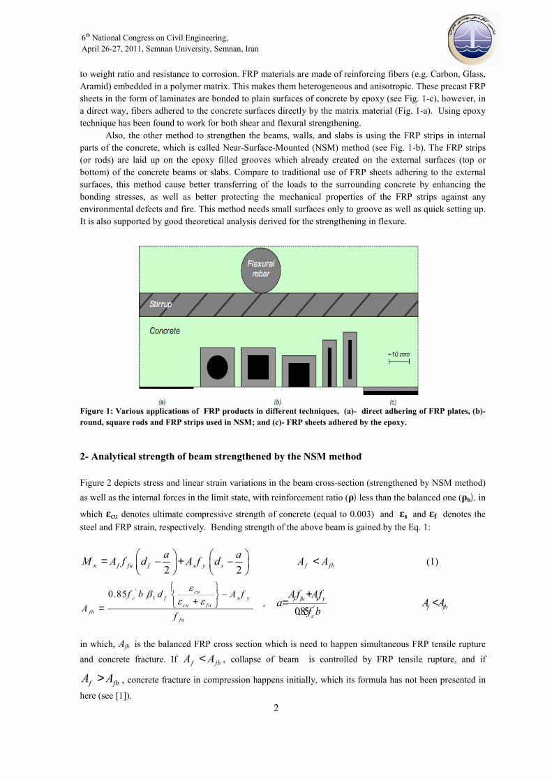
to weight ratio and resistance to corrosion. FRP materials are made of reinforcing fibers (e.g. Carbon, Glass, Aramid) embedded in a polymer matrix. This makes them heterogeneous and anisotropic. These precast FRP sheets in the form of laminates are bonded to plain surfaces of concrete by epoxy (see Fig. 1-c), however, in a direct way, fibers adhered to the concrete surfaces directly by the matrix material (Fig. 1-a). Using epoxy technique has been found to work for both shear and flexural strengthening. Also, the other method to strengthen the beams, walls, and slabs is using the FRP strips in internal parts of the concrete, which is called Near-Surface-Mounted (NSM) method (see Fig. 1-b). The FRP strips (or rods) are laid up on the epoxy filled grooves which already created on the external surfaces (top or bottom) of the concrete beams or slabs. Compare to traditional use of FRP sheets adhering to the external surfaces, this method cause better transferring of the loads to the surrounding concrete by enhancing the bonding stresses, as well as better protecting the mechanical properties of the FRP strips against any environmental defects and fire. This method needs small surfaces only to groove as well as quick setting up. It is also supported by good theoretical analysis derived for the strengthening in flexure.
Figure 1: Various applications of FRP products in different techniques, (a)- direct adhering of FRP plates, (b)- round, square rods and FRP strips used in NSM; and (c)- FRP sheets adhered by the epoxy.
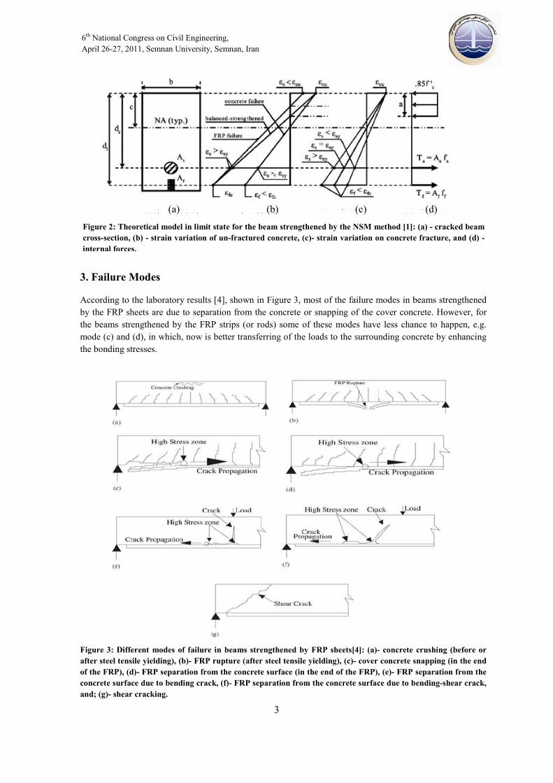
2- Analytical strength of beam strengthened by the NSM method Figure 2 depicts stress and linear strain variations in the beam cross-section (strengthened by NSM method) as well as the internal forces in the limit state, with reinforcement ratio (ρ) less than the balanced one (ρb), in
which εcu denotes ultimate compressive strength of concrete (equal to 0.003) and εs and εf denotes the steel and FRP strain, respectively. Bending strength of the above beam is gained by the Eq. 1:
2 2n f fu f s y s f fba aM A f d A f d A A = − + − <
(1)
'10.85 cu
c f s ycu fu
fbfu
f b d A fA
f
εβε ε
− + = , '0.85
f fu s yf fb
c
A f Afa A A
f b+
= <
in which, Afb is the balanced FRP cross section which is need to happen simultaneous FRP tensile rupture
and concrete fracture. If f fbA A< , collapse of beam is controlled by FRP tensile rupture, and if
f fbA A> , concrete fracture in compression happens initially, which its formula has not been presented in
here (see [1]).
6th National Congress on Civil Engineering, April 26-27, 2011, Semnan University, Semnan, Iran
3
3. Failure Modes
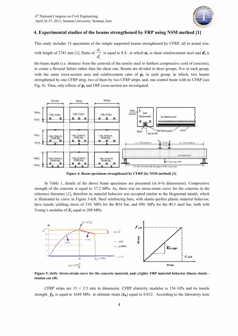
According to the laboratory results [4], shown in Figure 3, most of the failure modes in beams strengthened by the FRP sheets are due to separation from the concrete or snapping of the cover concrete. However, for the beams strengthened by the FRP strips (or rods) some of these modes have less chance to happen, e.g. mode (c) and (d), in which, now is better transferring of the loads to the surrounding concrete by enhancing the bonding stresses.
Figure 3: Different modes of failure in beams strengthened by FRP sheets[4]: (a)- concrete crushing (before or after steel tensile yielding), (b)- FRP rupture (after steel tensile yielding), (c)- cover concrete snapping (in the end of the FRP), (d)- FRP separation from the concrete surface (in the end of the FRP), (e)- FRP separation from the concrete surface due to bending crack, (f)- FRP separation from the concrete surface due to bending-shear crack, and; (g)- shear cracking.
Figure 2: Theoretical model in limit state for the beam strengthened by the NSM method [1]: (a) - cracked beam cross-section, (b) - strain variation of un-fractured concrete, (c)- strain variation on concrete fracture, and (d) - internal forces.
(a) (b) (c) (d)
6th National Congress on Civil Engineering, April 26-27, 2011, Semnan University, Semnan, Iran
4
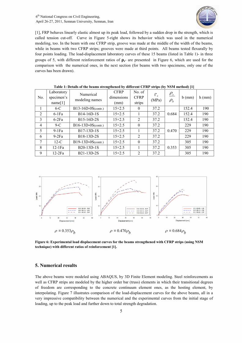
4. Experimental studies of the beams strengthened by FRP using NSM method [1] This study includes 15 specimens of the simple supported beams strengthened by CFRP, all in actual size,
with length of 2743 mm [1]. Ratio of v
s
ad
is equal to 8.4 , in which av is shear reinforcement steel and ds is
the beam depth (i.e. distance from the centroid of the tensile steel to furthest compressive cord of concrete), to create a flexural failure rather than the shear one. Beams are divided in three groups, five in each group, with the same cross-section area and reinforcement ratio of ρs in each group, in which, two beams strengthened by one CFRP strip, two of them by two CFRP strips, and; one control beam with no CFRP (see Fig. 4). Then, only effects of ρs and FRP cross-section are investigated.
Figure 4: Beam specimens strengthened by CFRP (by NSM method) [1]
In Table 1, details of the above beam specimens are presented (in b×h dimensions). Compressive strength of the concrete is equal to 37.2 MPa. As, there was no stress-strain curve for the concrete in the reference literature [1], therefore its material behavior was accepted similar to the Hognestad model, which is illustrated by curve in Figure 5-left. Steel reinforcing bars, with elastic-perfect plastic material behavior, have tensile yielding stress of 510. MPa for the Φ16 bar, and 490. MPa for the 13Φ steel bar, both with Young’s modulus of Es equal to 200 MPa.
Figure 5: (left)- Stress-strain curve for the concrete material, and; (right)- FRP material behavior (linear elastic -tension cut off)
CFRP strips are 15 × 2.5 mm in dimension. CFRP elasticity modulus is 136 GPa and its tensile strength ffu is equal to 1648 MPa at ultimate strain (εu) equal to 0.012. According to the laboratory tests
6th National Congress on Civil Engineering, April 26-27, 2011, Semnan University, Semnan, Iran
5
[1], FRP behaves linearly elastic almost up its peak load, followed by a sudden drop in the strength, which is called tension cut-off. Curve in Figure 5-right shows its behavior which was used in the numerical modeling, too. In the beam with one CFRP strip, groove was made at the middle of the width of the beams, while in beams with two CFRP strips; grooves were made at third points. All beams tested flexurally by four points loading. The load-displacement laboratory curves of these 15 beams (listed in Table 1)- in three groups of 5, with different reinforcement ratios of ρs- are presented in Figure 6, which are used for the comparison with the numerical ones, in the next section (for beams with two specimens, only one of the curves has been drawn).
Table 1: Details of the beams strengthened by different CFRP strips (by NSM method) [1]
h (mm) b (mm) s
b
ρρ
f’c
(MPa)
No. of CFRP strips
CFRP dimensions
(mm)
Numerical modeling names
Laboratory specimen’s
name[1] No.
190 152.4 0.684
37.2 015×2.5 B13-16D-0S(contr.) 6-C 1190 152.4 37.2 115×2.5 B14-16D-1S 6-1Fa 2190 152.4 37.2 215×2.5 B15-16D-2S 6-2Fa 3190 229
0.470 37.2 015×2.5 B16-13D-0S(contr.) 9-C 4
190 229 37.2 115×2.5 B17-13D-1S 9-1Fa 5190 229 37.2 215×2.5 B18-13D-2S 9-2Fa 6190 305
0.353 37.2 015×2.5 B19-13D-0S(contr.) 12-C 7
190 305 37.2 115×2.5 B20-13D-1S 12-1Fa 8190 305 37.2 215×2.5 B21-13D-2S 12-2Fa 9
0.353 bρ ρ= 0.470 bρ ρ= 0.684 bρ ρ=
Figure 6: Experimental load displacement curves for the beams strengthened with CFRP strips (using NSM technique) with different ratios of reinforcement [1].
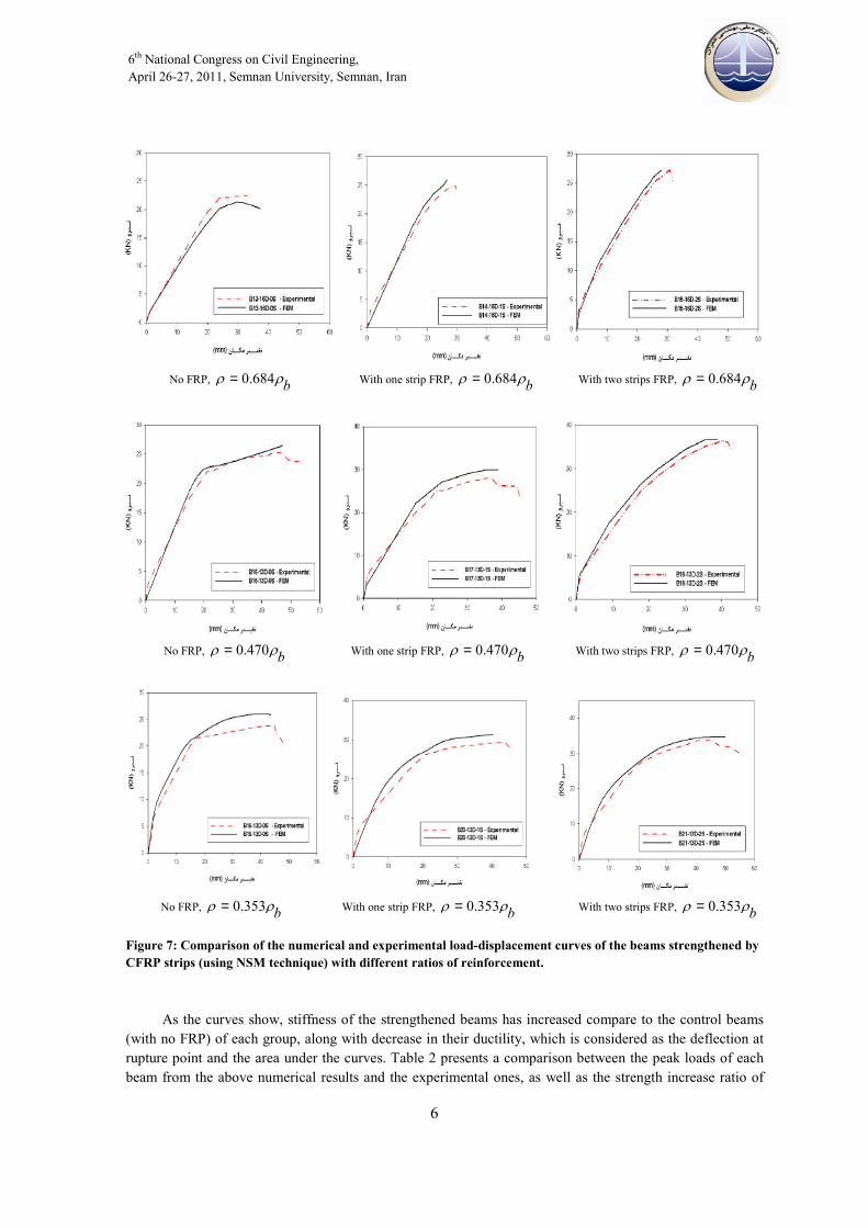
5. Numerical results The above beams were modeled using ABAQUS, by 3D Finite Element modeling. Steel reinforcements as well as CFRP strips are modeled by the higher order bar (truss) elements in which their transitional degrees of freedom are corresponding to the concrete continuum element ones, as the hosting element, by interpolating. Figure 7 illustrates comparison of the load-displacement curves for the above beams, all in a very impressive compatibility between the numerical and the experimental curves from the initial stage of loading, up to the peak load and further down to total strength degradation.
6th National Congress on Civil Engineering, April 26-27, 2011, Semnan University, Semnan, Iran
6
No FRP, 0.684 bρ ρ= With one strip FRP, 0.684 bρ ρ= With two strips FRP, 0.684 bρ ρ=
No FRP, 0.470 bρ ρ= With one strip FRP, 0.470 bρ ρ= With two strips FRP, 0.470 bρ ρ=
No FRP, 0.353 bρ ρ= With one strip FRP, 0.353 bρ ρ= With two strips FRP, 0.353 bρ ρ=
Figure 7: Comparison of the numerical and experimental load-displacement curves of the beams strengthened by CFRP strips (using NSM technique) with different ratios of reinforcement.
As the curves show, stiffness of the strengthened beams has increased compare to the control beams (with no FRP) of each group, along with decrease in their ductility, which is considered as the deflection at rupture point and the area under the curves. Table 2 presents a comparison between the peak loads of each beam from the above numerical results and the experimental ones, as well as the strength increase ratio of
6th National Congress on Civil Engineering, April 26-27, 2011, Semnan University, Semnan, Iran
7
the strengthened beams to the control ones. The results conclude that beams with lower reinforcement ratio have higher increase in their strength by increasing the FRP strips. For instance, there is an increase up to 34% for the beams with 0.353 bρ ρ= , while for the beam with 0.684 bρ ρ= , only 21% increase obtained,
both with two strips of FRP. Also, The above results conclude that for the specimens with higher reinforcements, increase in CFRP strips resulted lower efficiency in the strength, the same trend in the experiments. For instance, strength of the beam with two strips is only 6% more than the beam with one FRP strip, both with 0.684 bρ ρ= , while in similar beams with 0.353 bρ ρ= , 13% increase in strength is
observed, by adding another strip.
Table 2- Comparison of the numerical and experimental peak loads of the strengthened beams by NSM (note: SY denotes steel yielding failure, CC: compressive crushing of concrete, and; TR: tensile rupture of FRP)
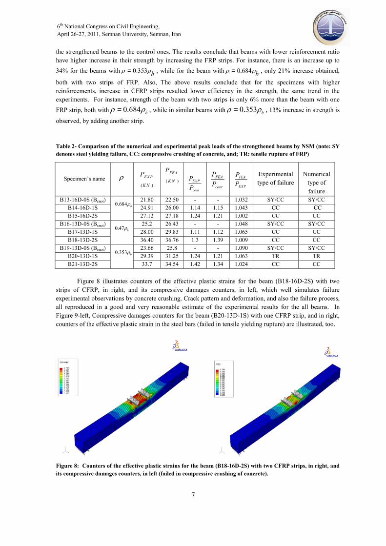
Figure 8 illustrates counters of the effective plastic strains for the beam (B18-16D-2S) with two
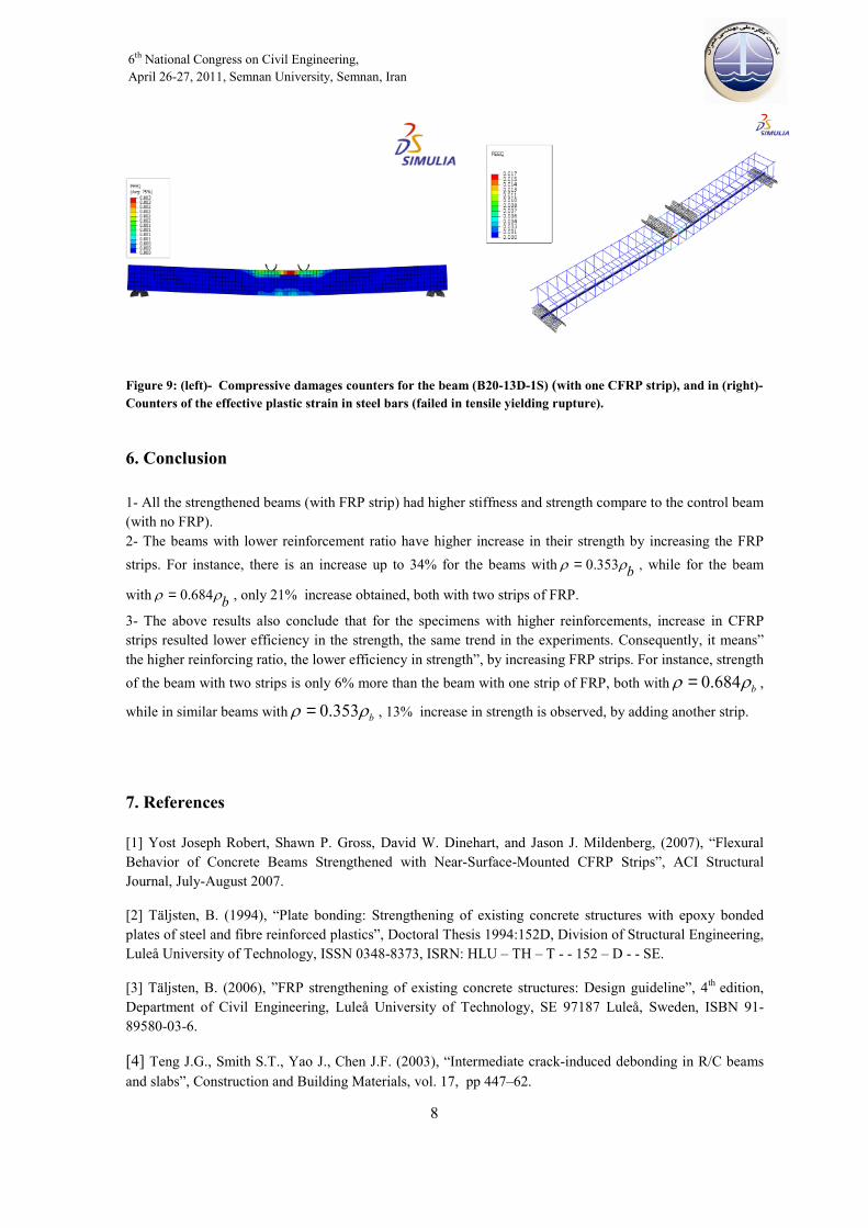
strips of CFRP, in right, and its compressive damages counters, in left, which well simulates failure experimental observations by concrete crushing. Crack pattern and deformation, and also the failure process, all reproduced in a good and very reasonable estimate of the experimental results for the all beams. In Figure 9-left, Compressive damages counters for the beam (B20-13D-1S) with one CFRP strip, and in right, counters of the effective plastic strain in the steel bars (failed in tensile yielding rupture) are illustrated, too.
Figure 8: Counters of the effective plastic strains for the beam (B18-16D-2S) with two CFRP strips, in right, and its compressive damages counters, in left (failed in compressive crushing of concrete).
Numerical type of failure
Experimental type of failure
FEA
EXP
PP
FEA
cont
PPEXP
cont
PP
( )
FEA
K N
P
( )
EX P
K N
PρSpecimen’s name
SY/CC SY/CC 1.032 --22.50 21.80 0.684 bρ
B13-16D-0S (Bcnot)CC CC1.043 1.15 1.14 26.00 24.91 B14-16D-1S CC CC1.002 1.21 1.24 27.18 27.12 B15-16D-2S
SY/CC SY/CC 1.048 --26.43 25.2 0.47 bρ
B16-13D-0S (Bcnot)CC CC1.065 1.12 1.11 29.83 28.00 B17-13D-1S CC CC1.009 1.39 1.3 36.76 36.40 B18-13D-2S
SY/CC SY/CC 1.090 --25.8 23.66 0.353 bρ
B19-13D-0S (Bcnot)TR TR1.063 1.21 1.24 31.25 29.39 B20-13D-1S CC CC1.024 1.34 1.42 34.54 33.7 B21-13D-2S
6th National Congress on Civil Engineering, April 26-27, 2011, Semnan University, Semnan, Iran
8
Figure 9: (left)- Compressive damages counters for the beam (B20-13D-1S) (with one CFRP strip), and in (right)- Counters of the effective plastic strain in steel bars (failed in tensile yielding rupture).
6. Conclusion 1- All the strengthened beams (with FRP strip) had higher stiffness and strength compare to the control beam (with no FRP). 2- The beams with lower reinforcement ratio have higher increase in their strength by increasing the FRP strips. For instance, there is an increase up to 34% for the beams with 0.353 bρ ρ= , while for the beam
with 0.684 bρ ρ= , only 21% increase obtained, both with two strips of FRP.
3- The above results also conclude that for the specimens with higher reinforcements, increase in CFRP strips resulted lower efficiency in the strength, the same trend in the experiments. Consequently, it means” the higher reinforcing ratio, the lower efficiency in strength”, by increasing FRP strips. For instance, strength of the beam with two strips is only 6% more than the beam with one strip of FRP, both with 0.684 bρ ρ= ,
while in similar beams with 0.353 bρ ρ= , 13% increase in strength is observed, by adding another strip.
7. References [1] Yost Joseph Robert, Shawn P. Gross, David W. Dinehart, and Jason J. Mildenberg, (2007), “Flexural Behavior of Concrete Beams Strengthened with Near-Surface-Mounted CFRP Strips”, ACI Structural Journal, July-August 2007.
[2] Täljsten, B. (1994), “Plate bonding: Strengthening of existing concrete structures with epoxy bonded plates of steel and fibre reinforced plastics”, Doctoral Thesis 1994:152D, Division of Structural Engineering, Luleå University of Technology, ISSN 0348-8373, ISRN: HLU – TH – T - - 152 – D - - SE.
[3] Täljsten, B. (2006), ”FRP strengthening of existing concrete structures: Design guideline”, 4th edition, Department of Civil Engineering, Luleå University of Technology, SE 97187 Luleå, Sweden, ISBN 91-89580-03-6.
[4] Teng J.G., Smith S.T., Yao J., Chen J.F. (2003), “Intermediate crack-induced debonding in R/C beams and slabs”, Construction and Building Materials, vol. 17, pp 447–62.