Embed Size (px)
Citation preview
11th World Congress on Computational Mechanics (WCCM XI)5th European Conference on Computational Mechanics (ECCM V)
6th European Conference on Computational Fluid Dynamics (ECFD VI)E. Onate, J. Oliver and A. Huerta (Eds)
USING HPC SOFTWARE FRAMEWORKS FORDEVELOPING BSIT: A GEOPHYSICAL IMAGING TOOL
Mauricio Hanzich∗, Juan Esteban Rodriguez∗, Natalia Gutierrez∗, Josep de
la Puente∗ and Jose Marıa Cela∗
∗ Barcelona Supercomputing Center - Centro Nacional de SupercomputacionGran Capita 2-4, Nexus I, 08034 Barcelona, Spain
e-mail: [email protected], web page: http://www.bsc.es
Key words: High Performance Computing, Software Frameworks, Efficiency, Reliability,Multi-platform, Multi-rheology
Abstract. HPC software is mandatory in many science and engineering fields. However,the development of such systems is not only expensive but difficult to maintain and extend.In this work we propose using two software frameworks that provide HPC developerswith tools oriented towards efficiency and resiliency, respectively. The efficiency-orientedframework automatically provides the developer with parallel strategies, such as domaindecomposition or asynchronous disk I/O so that the developer can concentrate on writingthe code specific to the problem at hand. At the same time, the framework structuresimplifies the portability of the code to different HPC architectures. On the other hand,the resiliency-oriented framework provides the developer with the means to launch parallelapplications in a distributed environment with full support to fault tolerance. As anexample, we show a whole geophysical imaging system called BSIT, which is built upon theusage of such frameworks and some additional supporting modules. In particular, BSIT’swave propagation libraries have been developed using the efficiency-oriented frameworkand its master-worker parallelism and distributed workflows have been built using theresiliency-oriented framework.
1 Introduction
Sequential software development is a costly enough task [13, 7], but developing par-allel software for a modern High Performance Computing (HPC) platform is even moreexpensive [8]. One way to minimize the development effort is to use software frameworks[11], that reduces the cost by providing some general functionalities while the specifics ofthe problem are left to the developer.
In this work we propose a set of two frameworks that are specific enough to accuratelyhandle many different physical problems, with a variety of physical models and numerical
1
Mauricio Hanzich, Juan Esteban Rodriguez, Natalia Gutierrez, Josep de la Puente and Jose Marıa Cela
approximations, that can be easily optimized for a series of target platforms with minimaleffort, while provides some resiliency to software and hardware failures.
Moreover, we present the Barcelona Subsurface Imaging Tools (BSIT 1) system as anexample usage of such frameworks for building geophysical imaging systems 2. Our par-ticular take for building BSIT exemplifies our effort in the particular case of solving theForward Modelling (FM [10]), Reverse Time Migration (RTM [4]) and Full WaveformInversion (FWI [15]) for the acoustic, elastic, viscoelastic and electromagnetic physicalmodels based upon different finite-difference schemes, both in time and frequency do-main. Some of these tools have recently come to play a major role in businesses suchas hydrocarbon exploration, as they offer the possibility of making the most out of thehighly expensive exploration surveys carried out in order to determine where a potentialreservoir can be found.
2 BSIT: Barcelona Subsurface Imaging Tools
In order to develop and maintain a single code that solves multiple geophysical imag-ing problems such as FM, RTM and FWI with their particular numerical, physical andcomputational needs, we propose using two frameworks specially tailored for fitting intomany different large-scale HPC platforms. The Environment for Assessing Performance(EAP) framework works at a single wave-propagation-simulation level, or shot level, pro-viding the common pieces related to a parallel application (e.g. domain decomposition orasynchronous input/output) by means of different propagator libraries, which focus on theefficiency of the processing. The Environment for Assessing Confidence (EAC), on theother hand, works at the work flow level, by distributing tasks to different computationalresources and gathering the results. This framework focuses on resiliency to node and jobfailures by means of fault tolerance protocols and checkpointing.
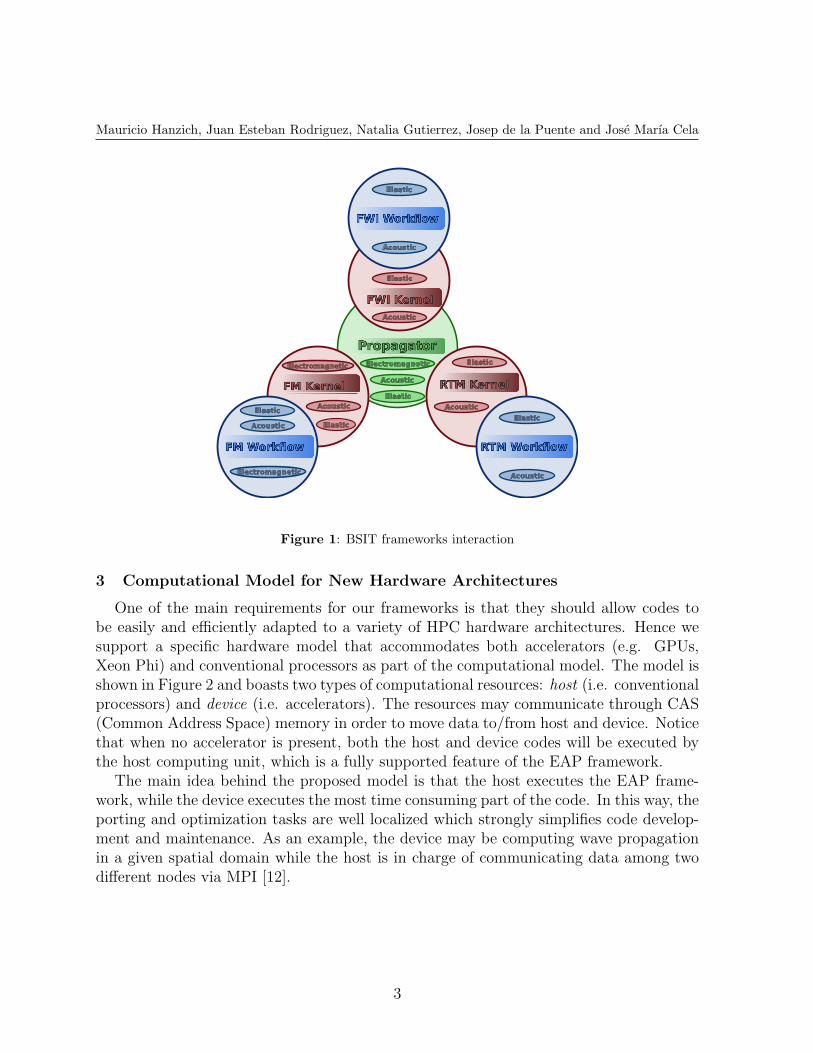
The EAC framework operates by distributing binaries among the available nodes. How-ever, the EAP framework produces a propagation library, hence kernels must be developedto connect both frameworks (see Figure 1). A kernel is a binary produced by configuringthe EAP framework with the proper functions to solve, for a single shot, a particular set ofphysics (e.g. elastic), geophysical tool (e.g. migration), numerical technique (e.g. explicitfinite-differences) and a specific hardware architecture (e.g. conventional processors oraccelerators such as GPUs [14] or Intel’s Xeon Phi [5]).
BSIT is our particular implementation of a geophysical imaging code using the EAPand EAC frameworks together with a set of support modules that provide them withsome basic functionality, such as parameters grabbing, logging system, error handling,geophysical data management (e.g. SEG-Y files [3]) and optimization tools, among others.
1http://www.bsc.es/bsit2developed for Repsol under Kaleidoscope project and the Repsol-BSC Research Center
2
Mauricio Hanzich, Juan Esteban Rodriguez, Natalia Gutierrez, Josep de la Puente and Jose Marıa Cela
RTM Kernel
Elastic
AcousticAcoustic
Elastic
Acoustic
ElasticAcoustic
Elastic
Acoustic
Elastic
Acoustic
Elastic
Elastic
Acoustic
ElectromagneticElectromagnetic
Electromagnetic
Figure 1: BSIT frameworks interaction
3 Computational Model for New Hardware Architectures
One of the main requirements for our frameworks is that they should allow codes tobe easily and efficiently adapted to a variety of HPC hardware architectures. Hence wesupport a specific hardware model that accommodates both accelerators (e.g. GPUs,Xeon Phi) and conventional processors as part of the computational model. The model isshown in Figure 2 and boasts two types of computational resources: host (i.e. conventionalprocessors) and device (i.e. accelerators). The resources may communicate through CAS(Common Address Space) memory in order to move data to/from host and device. Noticethat when no accelerator is present, both the host and device codes will be executed bythe host computing unit, which is a fully supported feature of the EAP framework.
The main idea behind the proposed model is that the host executes the EAP frame-work, while the device executes the most time consuming part of the code. In this way, theporting and optimization tasks are well localized which strongly simplifies code develop-ment and maintenance. As an example, the device may be computing wave propagationin a given spatial domain while the host is in charge of communicating data among twodifferent nodes via MPI [12].
3

Mauricio Hanzich, Juan Esteban Rodriguez, Natalia Gutierrez, Josep de la Puente and Jose Marıa Cela
Host
Device
Memory
(CAS)
Host
Device
Memory
(CAS)
MPI
Figure 2: BSIT supported computational model
4 EAP Framework: Environment for Assessing Performance
The EAP framework, whose structure is shown in Figure 3, provides the means forbuilding computational libraries for wave propagation simulators. The framework provideswith a series of empty slots on the workflow. A given configuration of the EAP is obtainedby filling the slots with the proper functions depending on the problem, architecture,method and physics at hand (e.g. electromagnetic modeling with finite-differences in thefrequency domain on GPUs). The framework is general enough to accommodate differentconfigurations by forcing all the functions provided by the developer to have the sameprototype, that is, the same parameters and return type.
Figure 3: EAP architecture
The responsibilities of the developer-defined functions depend on their slot in Figure 3,in particular:
• Config : Configures the rest of the EAP framework. Used by the Kernel (see Sec-tion 2).
4
Mauricio Hanzich, Juan Esteban Rodriguez, Natalia Gutierrez, Josep de la Puente and Jose Marıa Cela
• Initialize: Creates the data structures that are specific to the configuration.
• Scatter : Distributes input files (e.g. the velocity model) through the nodes collab-orating in the processing, if needed.
• Setup: Sets up a particular solver (or solvers) for a specific problem. This will beexplained in the following.
• Adapt : Adapt the output from one setup (solver) to the input of the next one, ifneeded.
• Gather : Gathers output data (seismograms, images,...) of multiple nodes.
• Finalize: Releases any allocated resources when the final state is reached.
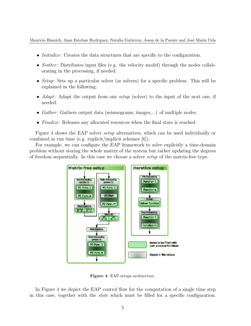
Figure 4 shows the EAP solver setup alternatives, which can be used individually orcombined in run time (e.g. explicit/implicit schemes [6]).
For example, we can configure the EAP framework to solve explicitly a time-domainproblem without storing the whole matrix of the system but rather updating the degreesof freedom sequentially. In this case we choose a solver setup of the matrix-free type.
Figure 4: EAP setups architecture.
In Figure 4 we depict the EAP control flow for the computation of a single time stepin this case, together with the slots which must be filled for a specific configuration.
5
Mauricio Hanzich, Juan Esteban Rodriguez, Natalia Gutierrez, Josep de la Puente and Jose Marıa Cela
Notice that computation stages are inserted between control orders to communicationand I/O stages so that the framework can overlap such stages at runtime (see [2] foran RTM example). In order to overlap memory transfer and computation when using adomain decomposition strategy, we separate the computation in Phases 1 and 2. Phase 1computations update values lying at a shared or communication zone between domains,so that these updated values can be transferred to neighboring domains simultaneously toupdating values belonging to exclusive zones at Phase 2. In addition, Phase 3 is availablein case there is some solver computation stage which needs the communication zone valuesupdated already.
The EAP framework allows us to use iterative solvers as well, which require of a fullyassembled (sparse) matrix. This is the case, for example, of frequency domain controlledsource electromagnetic (CSEM) modelling which, for large 3D problems, is too costlyfor direct solvers [1]. This solver setup (see Figure 3) requires choosing a matrix storageformat (e.g. CSR), solver type (e.g. SQMR), preconditioner (e.g. Jacobi) and data format(e.g. double complex).
Regarding the architecture of the iterative setup, Figure 4 shows the sequence of func-tions to be configured in the EAP framework. In this case, the sequence defined in the EAPis only composed of the Solver itself and Pre- & Post-processing functions, which mightnot be needed and depend on the problem being solved. In the above mentioned CSEMcase, for example, we have no pre-processing functions but there is a post-processing thatcalculates the total electromagnetic field from the secondary electric field calculated bythe iterative solver [1].
Different to the matrix-free case, once an iterative solver and matrix storage formatare incorporated to the library pool of the EAP, the developer is only asked to fill thesparse matrix and the right-hand side vector in order to finish an implicit configuration.Communications are restricted to the matrix-vector product, vector dot-product, vector-norm calculation and similar functions, which can be generally parallelized in the EAP,asynchronously when possible.
Notice that a direct solver could be used in the Solver slot as well with similar con-strains, as a special case requiring a single setup stage. Nevertheless, for very large 3Dproblems iterative solvers are often the only reasonable solution.
5 EAC Framework: Environment for Assessing Confidence
We have shown how the EAP framework is employed to build libraries that can beencapsulated in proper kernels. These kernels are binaries able to process a single simu-lation or shot, for a certain physics model, numerical method, architecture and imagingtool. However, in order to provide a complete geophysical imaging system it is neces-sary to process several thousands of shots in parallel. This includes interfacing fromdeveloper-built models and data formats to simplified data which is read and written bythe kernels, checking the correctness of the input data and kernels’ results or reacting to
6
Mauricio Hanzich, Juan Esteban Rodriguez, Natalia Gutierrez, Josep de la Puente and Jose Marıa Cela
hardware problems and data corruption (e.g. wrong headers, presence of NaNs3, etc.).The large amount of data to be processed, typically in the order of Terabytes (TB), andthe computational cost of processing which might take weeks to months in several HPCcomputing nodes, result in a high probability of facing some hardware or software failurethat compromises the whole processing.
The Environment for Assessing Confidence (EAC) framework provides the means tosolve the problem of managing the processing of thousand of parallel jobs of a criticalsystem, while providing with effective resiliency capabilities.
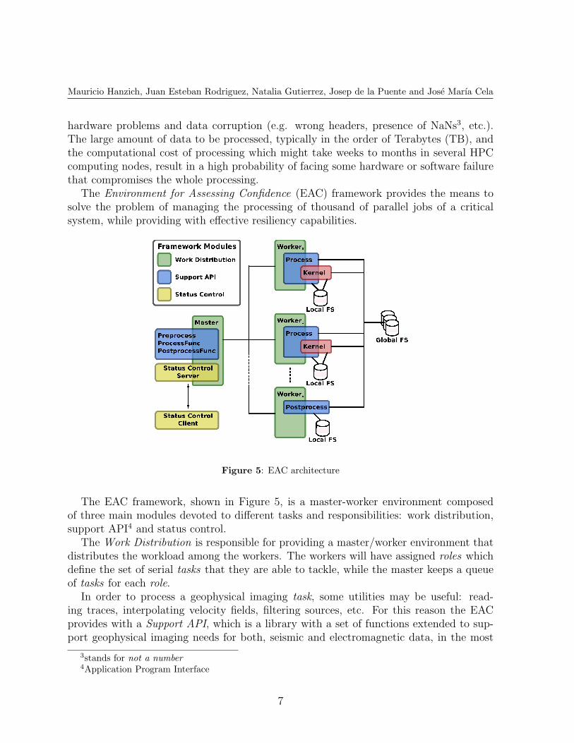
Figure 5: EAC architecture
The EAC framework, shown in Figure 5, is a master-worker environment composedof three main modules devoted to different tasks and responsibilities: work distribution,support API4 and status control.
The Work Distribution is responsible for providing a master/worker environment thatdistributes the workload among the workers. The workers will have assigned roles whichdefine the set of serial tasks that they are able to tackle, while the master keeps a queueof tasks for each role.
In order to process a geophysical imaging task, some utilities may be useful: read-ing traces, interpolating velocity fields, filtering sources, etc. For this reason the EACprovides with a Support API, which is a library with a set of functions extended to sup-port geophysical imaging needs for both, seismic and electromagnetic data, in the most
3stands for not a number4Application Program Interface
7
Mauricio Hanzich, Juan Esteban Rodriguez, Natalia Gutierrez, Josep de la Puente and Jose Marıa Cela
common formats available.Finally, the Status Control module provides an interactive control over the processing
being run. When a user (client) needs to change or retrieve some parameter of the runningprocess, he can use this module to connect to the status control (server) in the masterand perform an update or retrieve some status information.
In the following subsections we will depict each module and other characteristics ofEAC framework in depth.
5.1 Work Distribution and Results Gathering
Figure 5 shows the master-worker architecture provided by the EAC framework, thatprovides the means for processing thousands of shots in parallel.
To understand how a whole processing system may be built using the EAC framework,lets assume that we want to build a modeling system. Notice, that the same philosophycould be used to implement migrations, inversions or other type of systems that requireof a distributed system for an embarrassingly parallel processing of jobs.
On one hand, the Master of the system manages all the communications betweenitself and the worker nodes. However, there are some issues that must be defined by thedeveloper through a set of functions, such as: preprocess, process and postprocess.
The Preprocess function is composed of the set of tasks that must be done only oncebefore any further processing may proceed. In our modeling example we may need tointerpolate the input model, create some directories for output results, or create a databasewith the modeling survey. Notice that all of these tasks may be carried out using functionsprovided by the support API module.
Furthermore, every time the master needs to provide a worker with a new job, it needsthe means to do it. As this depends on the problem being solved, the developer mustprovide a function that tackles the issue. Such functions are defined as ProcessFunc andPostprocessFunc in Figure 5 and are responsible for creating the parameters needed forthe task to be executed by the worker.
The Worker, on the other hand is a program running in a node that process (i.e.executes) the job given by the master, and ask for more work whenever its runningjob finishes. Notice, that the same worker may execute different programs, which theframework understands as roles, along the total system execution. In particular thesupported roles are: processing, postprocessing and checkpointing. For example, while aworker is doing the modeling of one shot, the Process role in Figure 5, another may bemerging of a set of previously generated traces to an internal output file (the Postprocessrole in Figure 5).
The Processing will be responsible for preparing the data needed by the kernel, launchit and control the output for the processing a single shot. It should be noticed, that as thekernel is based on the EAP framework it is capable of using many computational nodesfor the processing of a shot. Hence, the worker may have more than one computationalassigned to do its task. In our modeling example, the kernel would be responsible for doing
8
Mauricio Hanzich, Juan Esteban Rodriguez, Natalia Gutierrez, Josep de la Puente and Jose Marıa Cela
the propagation of the wave, including absorbing boundary conditions, source insertion,seismogram creation, etc. The modeling processing should prepare the data for the kernelby cropping a submodel from the original model, retrieving the current shot informationfrom the modeling survey database, calculating kernel input/output and computationalparameters, etc. The processing of each task produces some partial output which mustbe integrated in the final output results. This is the aim of a worker running a task withthe role of Postprocessing. In the modeling example a postprocessing task/worker will beresponsible for merging the seismogram and/or illumination for a given shot into a globalresult. It is important to remark that, in order to avoid overloading the global file system,the postprocessing worker merges the partial results in a local copy of the final results.A Checkpointing task will be carried out periodically by the same postprocessing workerfor merging the local postprocessing results to the final results. In the modeling case, thecheckpointing may merge the traces of a postprocessing worker into the final results. Allthe information already checkpointed, should not be reprocessed in case of whole systemfailure.
Notice, that if there is no postprocessing task available when a postprocessing workerask for more work, then the master will assign it a processing task in order to avoid workeridleness.
5.2 Interactive Control of the Processing
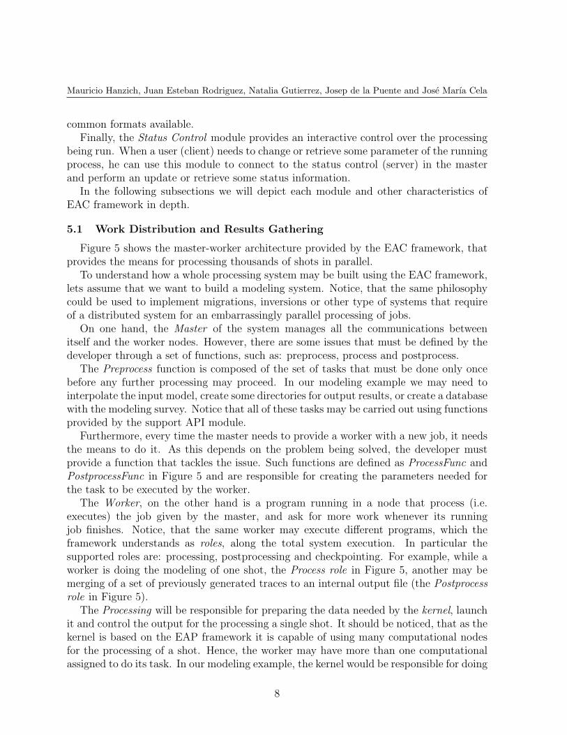
As already stated, seismic processing needs a huge amount of computational resourcesand time. Thus launching a process that is likely to run for weeks or even months withoutthe possibility of interacting with it may cause some serious problems regarding resourcesusage or efficiency. This, however, could be solved by using the interactive control moduleprovided by the EAC framework. Figure 6 shows how the master node includes a server towhich a user can connect in order to modify or monitor some parameters of the processing.Also, the master node keeps a status trace through a set of extra modules that allows theuser checking what exactly is happening at processing time.
Figure 6: EAC module for interaction and control
9
Mauricio Hanzich, Juan Esteban Rodriguez, Natalia Gutierrez, Josep de la Puente and Jose Marıa Cela
Notice that the client module of the framework exposed an API for the developer,who may build wherever interface to interact with the system. Either for parametersmonitoring, update or both.
Another feature provided by the status control module of the EAC framework is mal-leability. This is the capability of changing the amount of resources being allocated duringthe processing without affecting the results. As the processing may run for a long time,it is possible that some computational nodes may be needed for other, more prioritary,jobs; or that some extra resources may be available due to job completion. In any case,removing or adding resources (i.e. workers) to the processing while running is possiblethrough the API exposed by the client module (Status Control Client in Figure 6).
5.3 System Resiliency
Months of processing on large clusters are the normal case for real data, and even forsome complex synthetics ([9]). One main drawback of using a large number of compu-tational nodes for processing, is that the probability of failure grows with the number ofnodes. Traditional parallelism systems, such as MPI [12], do not manage well (or at all)the failure of a task in the process. Our proposed framework, has been designed to dealwith several types of failure, supporting both: detection and recovery, whenever possible.In the following we describe the type of failures that can be managed.
The first kind of failure to be tackled is the job processing and/or postprocessing failure.During the processing/postprocessing of a task, it is possible that some kind of problemprevents the process from continuing (e.g. a given source may fall outside the model or akernel failure arises). For detecting such failure the developer must relay on error codesreturned from the support API and its own controls to finish the processing with a propererror code. The EAC framework will receive the error from the worker and re-enter thetask in a queue of pending tasks, in case of a temporary failure (e.g. I/O congestion).This process, known as retry, will be done for the same task a limited number of times.Whenever the retry limit is reached for a job, it will be marked as failed in an outputreport from the framework. It is important to remark, that for postprocessing job failuresit is possible that not only the failed job must be enqueued. If some postprocessing taskssince the last checkpoint in the current worker were affected, they will be re-enqueued.
During a checkpointing task, the final results are modified for integrating some post-processing tasks results into it. In order to avoid corruption of the final results, locksand backup copies are created by the checkpoint task. If an error occurs while doing acheckpoint task, the system will restore backup copies.
Notice, that for a processing, postprocessing or checkpointing task, the system has auser-provided estimation of the maximum duration of that task (i.e. timeout). If thattimeout expires for a given task/worker, the system will realize that there has been anerror and recover depending on the failed task as explained above.
In addition, while processing any of the previous tasks, it is possible that the computa-tional node fails. In such cases the framework will notice and solve the situation without
10
Mauricio Hanzich, Juan Esteban Rodriguez, Natalia Gutierrez, Josep de la Puente and Jose Marıa Cela
user or developer intervention. To that goal, the workers send a report periodically tothe master indicating their state. If some report is not received on time, the frameworkassumes that the node has suffered a failure. At this point, the worker is removed formthe list of valid workers, and the task being processed by the worker goes back to theproper task-queue (either processing, postprocessing or checkpointing).
Finally, if the whole system goes down, the system can still be (manually) re-launchedand the processing will resume from the last successful checkpoint by inserting the re-maining tasks in the proper queues.
6 Conclusions
We have presented a set of frameworks that enable the developer tackling at once theefficiency and reliability problems that may arise when developing HPC software for large-scale applications. In our case we apply the frameworks to the geophysical imaging field forbuilding the BSIT system. This system provides different types of geophysical applications- including modeling, migration and inversion -, different wave physics,different numericalmethods and different HPC hardware architectures.
The first proposed framework, called EAP, provides the means to develop a solution toa tightly coupled problem such as the wave propagation needed for a geophysical imagingtool. The framework let the developer focus on the proper problem being implemented andits computational efficiency. The issues related with asynchronous domain decompositionand disk I/O are already provided by the framework.
The second framework, called EAC, provides the developer with a master-worker envi-ronment for processing several embarrassingly parallel tasks in a distributed environment.Moreover, the framework provides the system user (i.e. BSIT user) with the capabilityof interacting with the running application and even changing the allocated resourceswithout needing to restart the whole application. Finally, the environment provides witha high level of resiliency to software and hardware failure. In our case this is useful forcreating geophysical imaging systems that are able to process surveys of several thousandsof shots, which may take weeks or months to complete.
Acknowledgements
The authors want to thank Repsol for the permission to publish the present researchwork, carried out at the Repsol-BSC Research Center.
REFERENCES
[1] David L Alumbaugh, Gregory A Newman, Lydie Prevost, and John N Shadid. Three-dimensional wideband electromagnetic modeling on massively parallel computers.Radio Science, 31(1):1–23, 1996.
[2] Mauricio Araya-Polo, Javier Cabezas, Mauricio Hanzich, Miquel Pericas, EnricMorancho, Isaac Gelado, Muhhamad Shafiq, Felix Rubio, Jose Marıa Cela, Eduard
11
Mauricio Hanzich, Juan Esteban Rodriguez, Natalia Gutierrez, Josep de la Puente and Jose Marıa Cela
Ayguade, Nacho Navarro, and Mateo Valero. Assessing Accelerator-based HPC Re-verse Time Migration. IEEE Trans. Parallel Distrib. Syst., 2010.
[3] KM Barry, DA Cavers, and CW Kneale. Recommended standards for digital tapeformats. Geophysics, 40(2):344–352, 1975.
[4] Edip Baysal, Dan D Kosloff, and John WC Sherwood. Reverse time migration.Geophysics, 48(11):1514–1524, 1983.
[5] George Chrysos. Intel Xeon Phi Coprocessor (codename Knights Corner). Technicalreport, 10 2012.
[6] Chunlei Chu, Brian K Macy, and Phil D Anno. Approximation of pure acousticseismic wave propagation in tti media. Geophysics, 76(5):WB97–WB107, 2011.
[7] Edsger W. Dijkstra. “why is software so expensive?” An explanation to the hardwaredesigner. In Selected Writings on Computing: A Personal Perspective, pages 338–348.Springer-Verlag, 1982.
[8] Jack Dongarra, Dennis Gannon, Geoffrey Fox, and Ken Kennedy. The impact ofmulticore on computational science software. CTWatch Quarterly, 3(1):1–10, 2007.
[9] Michael Fehler. SEAM update: Elastic simulations. The Leading Edge, 31(1):24–25,2012.
[10] R. W. Graves. Simulating seismic wave propagation in 3D elastic media usingstaggered-grid finite differences. Bull. Seism. Soc. Am., 86(4):10911106, 1996.
[11] Jack Greenfield and Keith Short. Software factories: Assembling applications withpatterns, models, frameworks and tools. In Companion of the 18th Annual ACMSIGPLAN Conference on Object-oriented Programming, Systems, Languages, andApplications, OOPSLA ’03, pages 16–27, New York, NY, USA, 2003. ACM.
[12] William Gropp, Ewing Lusk, and Anthony Skjellum. Using MPI: Portable ParallelProgramming with the Message-Passing Interface. MIT Press, 10 1994.
[13] Robert E. Kraut and Lynn A. Streeter. Coordination in software development. Com-mun. ACM, 38(3):69–81, March 1995.
[14] Paulius Micikevicius. 3D finite difference computation on GPUs using CUDA. InProceedings of 2nd Workshop on General Purpose Processing on Graphics ProcessingUnits, GPGPU-2, page 7984, New York, NY, USA, 2009. ACM.
[15] Jean Virieux and Stephane Operto. An overview of full-waveform inversion in explo-ration geophysics. Geophysics, 74(6):WCC1–WCC26, 2009.
12


![NON-LINEAR ANALYSIS OF STEEL-CONCRETE BEAMS USING ...congress.cimne.com/iacm-eccomas2014/admin/files/filePaper/p3133.pdf · steel-concrete composite bridges [1] and (ii) elastoplastic](https://img.pdfslide.us/doc/110x75/5e738c9fa40ec15d9c253721/non-linear-analysis-of-steel-concrete-beams-using-steel-concrete-composite-bridges.jpg)


![MULTIDISCIPLINARY ANALYSIS OF THE DLR SPACELINER …congress.cimne.com/iacm-eccomas2014/admin/files/fileabstract/a1… · [6] Kuntsevich A., Kappel F. SolvOpt manual: The solver for](https://img.pdfslide.us/doc/110x75/606ff92e1e3b98598339e4a5/multidisciplinary-analysis-of-the-dlr-spaceliner-6-kuntsevich-a-kappel-f-solvopt.jpg)