Embed Size (px)
Citation preview

Cisco 910 IndustriaOL-31296-01
C H A P T E R 21
Using Device ManagerThe device manager is a graphic user interface (GUI) used to manage and configure the Cisco 910 Industrial Router and monitor the status of the router locally or remotely.
The recommended installation environment of the device manager is Cisco 910 Industrial Router OS (Linux). Internet Explorer 8.0, Internet Explorer 9.0, and Firefox 16 or above are the specified client end browsers.
To configure a router using the device manager, follow the steps described in these sections:
• Introduction to the Device Manager, page 21-1
• Logging In to the Device Manager, page 21-4
• Language Setting, page 21-4
• Using Dashboard, page 21-4
• Configuring the Network, page 21-8
• Configuring Platform Settings, page 21-35
• Monitoring the Status of System and Network, page 21-53
• Maintenance of the Router, page 21-60
Introduction to the Device ManagerThe device manager displays real-time views of router configuration and performance. It simplifies configuration tasks with features such as Express Setup for quickly setting up the router and its ports. It uses graphical, color-coded displays, such as the Front Panel view, graphs, and animated indicators to simplify monitoring tasks and to help you to identify and solve networking problems.
For comprehensive configuration and monitoring features, use the router command-line interface (CLI).
You can display the device manager from anywhere in your network through a web browser such as Microsoft Internet Explorer.
Note We recommend that you use the device manager in a secured session to protect your device manager session from unauthorized access. See the “Using Secured Sessions” section on page 21-3 for detailed information.
21-1l Router Software Configuration Guide, Release 1.0

Chapter 21 Using Device Manager Introduction to the Device Manager
Note The router displays settings and status only in English. In addition, entries on the router can only be in English.
Using the DashboardThe Dashboard provides information about the router and is the main window for monitoring the router status and its performance. It is the default window and appears each time that you display the device manager. For more information about the gauges, indicators, and graphs, see Dashboard.
Using the Toolbar IconsThe toolbar (Figure 21-1) is designed to provide options for refreshing the GUI, printing current page and accessing the online help. The title of the toolbar is “IR910 Series Device manager” with the router hostname.
Figure 21-1 Toolbar of the Device Manager
Table 21-1shows the descriptions of each options on the toolbar.
Using the MenusAfter you log in to the device manager, you will see the following menus on the left pane of the GUI:
• Dashboard— The primary window for monitoring overall router and port conditions.
• Network Configuration—Provides options to set up the basic network settings for the router and its ports, and to restart and to reset the router.
Table 21-1 Toolbar Options
Toolbar Icon Option Description
Refresh Update the information displayed on the Front Panel view, the graphs, and the configuration and monitoring windows.
Note Features that contain configurable parameters will not be refreshed.
Print Print a device manager window, such as the Dashboard or the Port Statistics window.
Note The menu or the Front Panel view cannot be printed. To print an online help page, click Print in the online help title bar.
Help Provide descriptions of the device manager features and procedures on how to use the features. The Help also provides links to LED status definitions and to support resources, such as the router documentation and technical assistance.
21-2Cisco 910 Industrial Router Software Configuration Guide, Release 1.0
OL-31296-01

Chapter 21 Using Device Manager Introduction to the Device Manager
• Platform Configuration—Provides options to set up network application. For examples. LLDP, SNMP, and AAA.
• Monitor—Provides options to display status and detailed run-time statistics every 60 seconds or when you click Refresh in the toolbar.
• Troubleshooting—Provides Ping and Traceroute to check network status.
• Maintenance—Provides an option to start a Telnet session and an option to upgrade the router software.
Detailed information about using these menus will be described in the following sections:
• Using the Dashboard
• Using the Toolbar Icons
• Using the Menus
• Using Secured Sessions
• Router Information
• System Information
• Port Utilization Graph
Using Secured SessionsThe router uses the Secure Sockets Layer (SSL) protocol to secure the HTTP communications between the router and your network management station. When you attempt to display the device manager, this protocol
• Authenticates the web-based connection between the router and your network management station.
• Encrypts and decrypts the information exchanged between the router and your network management station to protect the information from unauthorized access over the Internet.
SSL is disabled by default on the router. You can enable/disable SSL in HTTPs window.
In SSL enable state, when you first display the device manager, it displays a message that asks if you want a secured session with the router. If you choose Yes, the router displays another message that asks if you want to proceed by using the security certificate of the router. If you choose Yes to use the certificate, the router displays the device manager in secure mode.
If you choose No for either message, the router displays the device manager in unsecured mode.
There are other ways to start a secured device manager session:
• Enter https:// before the router IP address. (HTTP over SSL is abbreviated as HTTPS.)
• Click the Session: Standard | Secured link at the top right corner of the device manager window.
There are several ways to determine whether your device manager session is secured:
• Look at the URL in the browser Address field. A URL that starts with https:// means that the session is secured through SSL. A URL that starts with http:// means that the session is not secured.
• Look at the Session: Standard | Secured link at the top right corner of the device manager window.
– If the link appears as Session: Standard | Secured, the router is running a secured session.
– If the link appears as Session: Standard | Secured, the router is not running a secured session.
• Look for a locked padlock image at the bottom of your browser window. The locked padlock only appears if the session is secured.
21-3Cisco 910 Industrial Router Software Configuration Guide, Release 1.0
OL-31296-01
Chapter 21 Using Device Manager Logging In to the Device Manager
Logging In to the Device ManagerAccess the device manager at http://[router’s IP address] and log in to the web portal locally or remotely by entering the username and password of the admin account.
Language SettingThe GUI supports simplified Chinese and English by default. Other languages can be added easily when they are needed.
The GUI can detect the language the browser is using and display the pages in corresponding language when you log in for the first time. You can also change the language by selecting the proper language from the Language drop-down list as shown in Figure 21-2.
Figure 21-2 Language Setting of the Device Manager
Using DashboardThe Dashboard provides information about the router and is the main window for monitoring the router status and its performance. It is the default window and appears each time that you display the device manager. The Dashboard displays:
• Router Information
• System Information
• Port Utilization Graph
21-4Cisco 910 Industrial Router Software Configuration Guide, Release 1.0
OL-31296-01

Chapter 21 Using Device Manager Using Dashboard
Router InformationThe Router Information area provides reference information about the router (Figure 21-3).
Figure 21-3 Router Information
Table 21-2 shows the details of each options in the Router Information area.
Table 21-2 Router Information
Option Description
Name The name of this router configured during Express Setting or through the command-line interface (CLI). If no name was provided, this field displays the default name, Router.
Product ID The model of this router. This information cannot be modified.
IP Address The IP address of this router configured during Express Setting or through the CLI.
Version ID The version ID of the router. This information cannot be changed.
Serial Number
The serial number of this router. This information cannot be modified.
Software The software version that the router is running. This information is updated when you upgrade the router software.
Contact The name of the person assigned as the administrative contact for this router. This information is configured during SNMP window or through the CLI.
Location The location identified for router. This information is configured during SNMP window or through the CLI.
21-5Cisco 910 Industrial Router Software Configuration Guide, Release 1.0
OL-31296-01

Chapter 21 Using Device Manager Using Dashboard
System InformationThe System Information area has the gauges and indicators that show the overall status of the router (Figure 21-4).
Figure 21-4 System Information
Data is collected at each 60-second system refresh. To manually refresh the gauges, click Refresh in the toolbar. The following sections describes these gauges and indicators:
• CPU Used Gauge
• Memory Used Gauge
• Bandwidth Used Gauge
• Packet Error Gauge
CPU Used Gauge
The CPU Used gauge shows the total CPU percentage of the router being used. You can also move the pointer over the gauge to see this percentage. Each bar in the gauge represents 10 percent and does not show increments that are less than 10 percent. The gauge does not show total CPU used under 5 percent.
Memory Used Gauge
The Memory Used gauge shows the total memory percentage of the router being used. You can also move the pointer over the gauge to see this percentage. Each bar in the gauge represents 10 percent and does not show increments that are less than 10 percent. The gauge does not show total memory used under 5 percent.
Bandwidth Used Gauge
The Bandwidth Used gauge shows the total receive percentage of the router bandwidth being used. You can also move the pointer over the gauge to see this percentage. Each bar in the gauge represents 10 percent and does not show increments that are less than 10 percent. The gauge does not show total bandwidth under 5 percent.
The Bandwidth Used gauge changes as the router experiences the network activity from devices sending data packets through the network. As network activity increases, contention between devices to send data through the network increases. Contention can cause collisions (two devices sending data at the same time), and the devices need to resend their data. Excessive collisions can cause transmission delays. For example, users might experience excessive delays in sending or receiving information through the network.
21-6Cisco 910 Industrial Router Software Configuration Guide, Release 1.0
OL-31296-01

Chapter 21 Using Device Manager Using Dashboard
As you monitor the router, note whether the bandwidth usage is consistently high. This can mean there is congestion in the network. If the router reaches its maximum bandwidth (above 90 percent usage) and its buffers become full, it begins to discard the data packets that it receives. Some packet loss in the network is not considered unusual, and the router is configured to help to recover lost packets (such as by signaling to other devices to resend data). However, excessive packet loss can create packet errors, which can degrade overall network performance.
To reduce congestion, consider segmenting the network into subnetworks that are connected by other switches or routers. Look for other causes, such as faulty devices or connections, that can also increase bandwidth usage on the router.
Packet Error Gauge
The actual percentage appears below the graphic. You can also display the actual percentage by moving the pointer over the gauge. Each bar in the gauge represents 10 percent, and does not show increments that are less than 10 percent. The gauge does not show packet error percentages that are less than 5 percent.
The packet error percentage is calculated by comparing two values:
• The total number of packets that are sent and received.
• The total number of packets with errors that are sent and received.
If the packet-error percentage is high (that is, above 10 percent), the router bandwidth usage might also be too high (a sign that the network is congested). Other causes for packet errors are faulty cabling and port misconfiguration, such as a duplex-mode mismatch. These problems can cause network users to experience intermittent connectivity or loss of connectivity to network resources (such as servers and printers) or to the Internet. Excessive collisions can cause transmission delays. For example, users might experience excessive delays in sending or receiving information through the network.
The Port Statistics window displays some of the types of packet errors collected by the router. Table 21-3 shows some cause for some network problems.
Table 21-3 Types of Packet Errors
Option Description
Runt packets Packets that are smaller than the allowed minimum size (less than 64 bytes).
Giant packets Packets that are larger than the allowed maximum size (more than 1518 bytes).
Cyclic redundancy checksum (CRC) errors
Errors generated by the originating LAN station or far-end device do not match the checksum calculated from the data received. On a LAN, this usually means noise or transmission problems on the LAN interface or the LAN bus itself. A high number of CRCs is usually the result of collisions or of a station sending bad data.
Overrun packets Packets that the receiving device was unable to receive.
Frame packets Packets received because of a CRC error and a non-integer number of octets. On a LAN, this is usually the result of collisions or a malfunctioning Ethernet device.
Ignored packets Packets that the interface ignores because the interface hardware is low on internal buffers. These buffers are different from the system buffers. Broadcast storms and bursts of noise can cause the ignored count to increase.
21-7Cisco 910 Industrial Router Software Configuration Guide, Release 1.0
OL-31296-01

Chapter 21 Using Device Manager Configuring the Network
Port Utilization GraphThe Port Utilization graph displays the receive utilization (blue) and transmit utilization (purple) for all the ports. Move the pointer over the color-coded bars in the graph for the utilization percentage for the specific ports.
Note Using the Refresh option from your browser reloads the device manager.
For send and receive statistics for each port, click View Port Statistics on the top right of the Port Utilization graph (see Figure 21-5).
Figure 21-5 Port Utilization Graph
The proportion of bandwidth allocated to each port can be based on symmetric (evenly distributed bandwidth to each port) or asymmetric (unlike, or unequal, bandwidth among some ports) connections.
Symmetric connections are among ports with the same bandwidth, such as all 100BASE-T. Symmetric connections are optimized for a reasonably distributed traffic load, such as in a peer-to-peer desktop environment.
Asymmetric connections are among ports with unlike bandwidth, such as a combination of 10BASE-T, 100BASE-T, and 1000BASE-T. Asymmetric connections are optimized for client/server traffic flows in which multiple clients simultaneously communicate with a server, requiring more bandwidth dedicated to the server port to prevent a bottleneck at that port.
Bandwidth allocation can also be based on whether the connection is operating in half-duplex or full-duplex mode.
Configuring the NetworkYou can perform the following network configuration using the Network Configuration menus:
• Configuring Ports
• Configuring Express Settings
• Configuring Layer 3 Settings
• Configuring Wireless
• Configuring 3G USB Modem
• Configuring PPPoE
• Configuring VLAN
• Configuring VPN
21-8Cisco 910 Industrial Router Software Configuration Guide, Release 1.0
OL-31296-01

Chapter 21 Using Device Manager Configuring the Network
• Configuring DHCP
• Configuring NAT
Configuring PortsUse the Port Settings window to configure the basic port settings. These settings determine how data is received and sent between the router and the attached device. You can change these settings to fit your network needs and to troubleshoot network problems.
Follow these steps to configure the port:
Step 1 Click Port under Network Configuration in the left pane. The Port Settings window is displayed, as shown in Figure 21-6.
Figure 21-6 Port Settings
Step 2 You can view or configure the following information of the port:
• Port—Name of the port, including the type of the port (for example, Gi for GigabitEthernet), the module slot number (for example, 0), and the specific port number.
• Description—Description of the port. Valid values are strings with less than 256 characters. You are recommended to provide a port description to help identify the port during monitoring and troubleshooting. The description can be the location of the connected device or the name of the person using the connected device.
• Enable—The status of the port. Check Enabled to enable the port. Uncheck the check box of a port to administratively (manually) shut down the port. It is recommended to disable the port if the port is not in use and is not attached to a device.
• Speed—The operating speed of the port. Choose the speed from the drop-down list:
– Auto—Sets the interface to auto negotiate speed. This is the default.
– 10 MB—Sets the interface to 10 MB (for TX interface only).
– 100 MB—Sets the interface to 100 MB (for FX interface only).
– 1000 MB—Sets the interface to 1 GB (for Gigabit Ethernet interface only).
• Duplex—The duplex mode of the port. The default is Auto. Choose the duplex mode from the drop-down list:
– Auto (auto negotiation)—The connected device can negotiate with the router. This is the default.
– Full (full duplex)—Both devices can send data at the same time.
21-9Cisco 910 Industrial Router Software Configuration Guide, Release 1.0
OL-31296-01

Chapter 21 Using Device Manager Configuring the Network
– Half (half duplex)—Both devices cannot send data at the same time.
Note On a Gigabit Ethernet port, you cannot set the port to half duplex if the port speed is set to Auto.
Step 3 Click Submit to save the changes and Clear to discard the unsaved changes.
Configuring Express SettingsThe router can operate without an IP address assigned to it. However, you are recommended to set up the router with an IP address so that you can manage it through the device manager.
Use the Express Settings window to setup the router. Follow these steps to configure the express settings:
Step 1 Click Express Settings under Network Configuration in the left pane. The Express Settings window is displayed, as shown in Figure 21-7.
Figure 21-7 Express Settings
Step 2 Enter the IPv4 or IPv6 address of the router.
Step 3 Click the drop-down arrow in the IPv4 Netmask field, and select an IP Subnet Mask; or enter Subnet prefix length field when you use IPv6, and the range is 0 to 128.
Step 4 Enter the IP address for the IPv4 or IPv6 default gateway in the Default Gateway field.
Step 5 Enter the password in the Switch Enable Password field. The password can be from 1 to 25 alphanumeric characters, can start with a number, is case sensitive, and can have embedded spaces. The password cannot contain a question mark (?) or a tab, and cannot have spaces at the beginning or end. The default is cisco.
Note To complete the initial setup, you must change the password.
Step 6 Enter the password again in the Confirm Password field.
21-10Cisco 910 Industrial Router Software Configuration Guide, Release 1.0
OL-31296-01

Chapter 21 Using Device Manager Configuring the Network
Step 7 (Optional) Enter a host name for the router in the Host Name field. The host name is limited to 31 alphanumeric characters and embedded spaces are not allowed.
Step 8 (Optional) Specify the SSH Login Timeout value in seconds. The value should not to exceed 120 seconds. The default is 120.
Step 9 (Optional) Specify the number of authentication retries in the SSH Auth Retries field. The value range is not to exceed 5 authentication retries. The default is 3.
Step 10 Click Submit to save the changes and Clear to discard the unsaved changes.
Configuring Layer 3 SettingsYou can configure the following layer 3 settings on the router:
• Configuring Management VLAN
• Configuring Gigabit Ethernet Interface
• Configuring Wi-Fi Station
• Configuring Route
• Configuring DNS
Configuring Management VLAN
The management VLAN is the broadcast domain where management traffic is sent between specific users or devices. It provides broadcast control and security for management traffic that should be limited to a specific group of users (such as the administrators of your network). It also ensures secure, administrative access to all devices in the network at all times.
Follow these steps to configure the IP address of the management VLAN:
Step 1 Click Layer 3 Settings under Network Configuration in the left pane. The VLAN tab of Layer 3 Settings window is displayed, as shown in Figure 21-8.
21-11Cisco 910 Industrial Router Software Configuration Guide, Release 1.0
OL-31296-01

Chapter 21 Using Device Manager Configuring the Network
Figure 21-8 Layer 3 Settings–VLAN
Step 2 Choose a VLAN ID from the Management VLAN ID drop-down list. The ID can be from 1 to 4094. This information cannot be modified through the device manager. Use the CLI to change this setting.
Note Make sure that the router and your network management station are in the same VLAN. Otherwise, you will lose management connectivity to the switch.
Step 3 If you use IPv4 address, choose Static or DHCP from the IPv4 Connection Type drop down list.
Step 4 If you choose Static, enter the address and netmask in the IPv4 Address and IPv4 Netmask fields; If you choose DHCP, the IPv4 Address and IPv4 Netmask fields will obtain the values automatically.
Step 5 If you use IPv6 address, follow these guidelines to choose configure Dynamic Address setting:
• Choose Dynamic Stateful Auto-Configuration if you want to enable the DHCPv6 client function on the interface and obtain IPv6 address automatically from a DHCPv6 server.
• Choose Dynamic Stateless Auto-Configuration if you want to enable stateless auto-configuration on the interface and to configure IPv6 addresses based on prefixes received in Router Advertisement messages.
Step 6 Enter IPv6 Prefix Address in the Static Address field if you want to produce a static IPv6 global address. Enter related IPv6 Default Router and IPv6 DNS Server address.
Step 7 Click Submit to save the changes and Clear to discard the unsaved changes.
Configuring Gigabit Ethernet Interface
Follow these steps to configure the Gigabit Ethernet (GE) interface on the router:
Step 1 Click Layer 3 Settings under Network Configuration in the left pane and then click GE in the right pane. The GE tab is displayed, as shown in Figure 21-9.
21-12Cisco 910 Industrial Router Software Configuration Guide, Release 1.0
OL-31296-01

Chapter 21 Using Device Manager Configuring the Network
Figure 21-9 Layer 3 Settings–GE
Step 2 If you use IPv4 address, choose Static or DHCP from the IPv4 Connection Type drop down list.
Step 3 If you choose Static, enter the address and netmask in the IPv4 Address and IPv4 Netmask fields; If you choose DHCP, the IPv4 Address and IPv4 Netmask fields will obtain the values automatically.
Step 4 If you use IPv6 address, follow these guidelines to choose configure Dynamic Address setting:
• Choose Dynamic Stateful Auto-Configuration if you want to enable the DHCPv6 client function on the interface and obtain IPv6 address automatically from a DHCPv6 server.
• Choose Dynamic Stateless Auto-Configuration if you want to enable stateless auto-configuration on the interface and to configure IPv6 addresses based on prefixes received in Router Advertisement messages.
Step 5 Enter IPv6 Prefix Address in the Static Address field if you want to produce a static IPv6 global address. Enter related IPv6 Default Router and IPv6 DNS Server address.
Step 6 Click Submit to save the changes and Clear to discard the unsaved changes.
Configuring Wi-Fi Station
Follow these steps to configure the Wi-Fi Station IP address on the router:
Step 1 Click Layer 3 Settings under Network Configuration in the left pane and then click WiFi Station in the right pane. The Wi-Fi Station tab is displayed, as shown in Figure 21-10.
21-13Cisco 910 Industrial Router Software Configuration Guide, Release 1.0
OL-31296-01

Chapter 21 Using Device Manager Configuring the Network
Figure 21-10 Layer 3 Settings–Wi-Fi Station
Step 2 If you use IPv4 address, choose Static or DHCP from the IPv4 Connection Type drop down list.
Step 3 If you choose Static, enter the address and netmask in the IPv4 Address and IPv4 Netmask fields; If you choose DHCP, the IPv4 Address and IPv4 Netmask fields will obtain the values automatically.
Step 4 If you use IPv6 address, follow these guidelines to choose configure Dynamic Address setting:
• Choose Dynamic Stateful Auto-Configuration if you want to enable the DHCPv6 client function on the interface and obtain IPv6 address automatically from a DHCPv6 server.
• Choose Dynamic Stateless Auto-Configuration if you want to enable stateless auto-configuration on the interface and to configure IPv6 addresses based on prefixes received in Router Advertisement messages.
Step 5 Enter IPv6 Prefix Address in the Static Address field if you want to produce a static IPv6 global address. Enter related IPv6 Default Router and IPv6 DNS Server address.
Step 6 Click Submit to save the changes and Clear to discard the unsaved changes.
Configuring Route
Follow these steps to configure IPv4 or IPv6 route on the router:
Step 1 Click Layer 3 Settings under Network Configuration in the left pane and then click Route in the right pane. The Route tab is displayed, as shown in Figure 21-11.
21-14Cisco 910 Industrial Router Software Configuration Guide, Release 1.0
OL-31296-01

Chapter 21 Using Device Manager Configuring the Network
Figure 21-11 Default Route Settings
Step 2 To configure IPv4 route:
a. Choose an interface from the Interface drop-down list in the IPv4 Default Route Setting area.
b. Enter the IP address of the IPv4 default gateway and metric.
To configure IPv6 route:
a. Choose an interface from the Interface drop-down list in the IPv6 Default Route Setting area.
b. Enter the IP address of the IPv6 default gateway and metric.
Step 3 Click Submit to save the changes and Clear to discard the unsaved changes.
Configuring DNS
Follow these steps to configure DNS information on the router:
Step 1 Click Layer 3 Settings under Network Configuration in the left pane and then click DNS in the right pane. The DNS tab is displayed, as shown in Figure 21-12.
21-15Cisco 910 Industrial Router Software Configuration Guide, Release 1.0
OL-31296-01

Chapter 21 Using Device Manager Configuring the Network
Figure 21-12 DNS Settings
Step 2 Enter the IPv4 or IPv6 DNS server address in the Static DNS Server field. You can also set the value to blank.
Step 3 Click Submit to save the changes and Clear to discard the unsaved changes.
Configuring WirelessYou can configure the following wireless settings on the router:
• Switching Wireless Mode
• Configuring AP Mode
• Configuring Station Mode
Switching Wireless Mode
You can get the information of current wireless mode and switch the wireless mode in the Wireless Mode tab.
Follow these steps to view or switch wireless mode on the router:
Step 1 Click Wireless under Network Configuration in the left pane. The Wireless Mode tab is displayed, as shown in Figure 21-13.
21-16Cisco 910 Industrial Router Software Configuration Guide, Release 1.0
OL-31296-01

Chapter 21 Using Device Manager Configuring the Network
Figure 21-13 Wireless Mode
Step 2 The current wireless mode is displayed in the right pane.
Step 3 (Optional) Click the Switch to STA mode or Switch to AP mode button to change current wireless mode. If you change the wireless mode, there will be a pop up windows warning you the system should be switched mode to apply the changes and asking whether you want to continue or not.
Step 4 Click Submit to save the changes and Clear to discard the unsaved changes.
Configuring AP Mode
Use the AP Configuration tab to configure AP settings and manage the AP profiles.
Configuring AP Settings
Follow these steps to configure AP settings on the router:
Step 1 Click Wireless under Network Configuration in the left pane and then click AP Configuration in the right pane. The AP Configuration tab is displayed, as shown in Figure 21-14.
21-17Cisco 910 Industrial Router Software Configuration Guide, Release 1.0
OL-31296-01

Chapter 21 Using Device Manager Configuring the Network
Figure 21-14 AP Configuration
Step 2 Choose a value for the fields with drop-down list and enter a value for the fields with a text box. For detailed information about AP settings, see the chapter of Configuring Wi-Fi.
Step 3 Click Submit to save the changes and Cancel to discard the unsaved changes.
Managing AP Profiles
Use the AP profile area of the AP Configuration tab to add, edit, or delete AP profiles.
Follow these steps to add an AP profile:
Step 1 Click Wireless under Network Configuration in the left pane and then click AP Configuration in the right pane. The AP Configuration tab is displayed, as shown in Figure 21-14.
Step 2 To create a n AP profile, click Add in the AP Profile area to add a row in the profile binding table. The Add Profile window is displayed, as shown in Figure 21-15.
21-18Cisco 910 Industrial Router Software Configuration Guide, Release 1.0
OL-31296-01

Chapter 21 Using Device Manager Configuring the Network
Figure 21-15 Add AP Profile
Step 3 Enter SSID in the SSID field,
Step 4 Choose authentication mode and encryption mode.
Step 5 Click OK to add the new profile.
Follow these steps to delete an AP profile:
Step 1 Click Wireless under Network Configuration in the left pane and then click AP Configuration in the right pane. The AP Configuration tab is displayed, as shown in Figure 21-14.
Step 2 Choose an profile in the binding table and click Delete to delete that row.
Follow these steps to modify an AP profile:
Step 1 Click Wireless under Network Configuration in the left pane and then click AP Configuration in the right pane. The AP Configuration tab is displayed, as shown in Figure 21-14.
Step 2 Choose an profile in the binding table and click Edit. The Edit Profile window is displayed, with the same options with the Add Profile window.
Step 3 Enter SSID in the SSID field,
Step 4 Choose authentication mode and encryption mode.
Step 5 Click OK to save the changes.
21-19Cisco 910 Industrial Router Software Configuration Guide, Release 1.0
OL-31296-01

Chapter 21 Using Device Manager Configuring the Network
Configuring Station Mode
Use the STA Configuration tab to configure station mode settings and manage the STA profiles.
Configuring STA Settings
Follow these steps to configure STA settings on the router:
Step 1 Click Wireless under Network Configuration in the left pane and then click STA Configuration in the right pane. The STA Configuration tab is displayed, as shown in Figure 21-16.
Figure 21-16 STA Configuration
Step 2 Check Auto-connect to enable or uncheck to disable auto-connect feature.
Step 3 Click Submit to save the changes and Clear to discard the unsaved changes.
Managing STA Profiles
You can add, edit, or delete STA profiles, connect to or disconnect from an SSID, and change the SSID prefer list in the STA Configuration tab.
Follow these steps to add an STA profile:
Step 1 Click Wireless under Network Configuration in the left pane and then click STA Configuration in the right pane. The STA Configuration tab is displayed, as shown in Figure 21-16.
Step 2 Click Add to add a row in the profile binding table. The Add Profile window is displayed, as shown in Figure 21-17.
21-20Cisco 910 Industrial Router Software Configuration Guide, Release 1.0
OL-31296-01

Chapter 21 Using Device Manager Configuring the Network
Figure 21-17 Add STA Profile
Step 3 Enter the SSID directly in the SSID field and choose encryption mode from the drop-down list, or click Scan to list all SSIDs the router have scanned and choose one.
If you click Scan, the Scan SSID window opens. Choose the channel and click Scan. The SSIDs could be scanned and shown in the SSID list, as shown in Figure 21-18. Click Add to select the SSID.
Figure 21-18 Scaned SSID List
Step 4 Choose encryption mode and enter the encryption key.
Step 5 Click OK to add the new profile.
21-21Cisco 910 Industrial Router Software Configuration Guide, Release 1.0
OL-31296-01

Chapter 21 Using Device Manager Configuring the Network
Follow these steps to connect to or disconnect from an SSID:
Step 1 Click Wireless under Network Configuration in the left pane and then click STA Configuration in the right pane. The STA Configuration tab is displayed, as shown in Figure 21-16.
Step 2 Choose an SSID from the list and click Connect or Disconnect.
Note If the SSID you select is connected, the button will be shown as Disconnect.
Follow these steps to modify an STA profile:
Step 1 Click Wireless under Network Configuration in the left pane and then click STA Configuration in the right pane. The STA Configuration tab is displayed, as shown in Figure 21-16.
Step 2 Choose an profile in the binding table and click Edit. The Edit Profile window is displayed, with the same options of the Add Profile window.
Step 3 Enter SSID in the SSID field.
Step 4 Choose authentication mode and encryption mode.
Step 5 Click OK to save the changes.
Follow these steps to change the SSID prefer list:
Step 1 Click Wireless under Network Configuration in the left pane and then click STA Configuration in the right pane. The STA Configuration tab is displayed, as shown in Figure 21-16.
Step 2 Choose an profile in the binding table and click Priority. The Priority Profile window is displayed.
Step 3 Choose an profile in the list and click Move up or Move down to change the order.
Note In AP mode, the Connect/Disconnect button in STA configuration tab is disabled. You can edit SSID profiles, but you cannot connect to any SSID in the STA configuration.
Follow these steps to delete an STA profile:
Step 1 Click Wireless under Network Configuration in the left pane and then click STA Configuration in the right pane. The STA Configuration tab is displayed, as shown in Figure 21-16.
Step 2 Choose an profile in the list and click Delete to delete that row.
21-22Cisco 910 Industrial Router Software Configuration Guide, Release 1.0
OL-31296-01
Chapter 21 Using Device Manager Configuring the Network
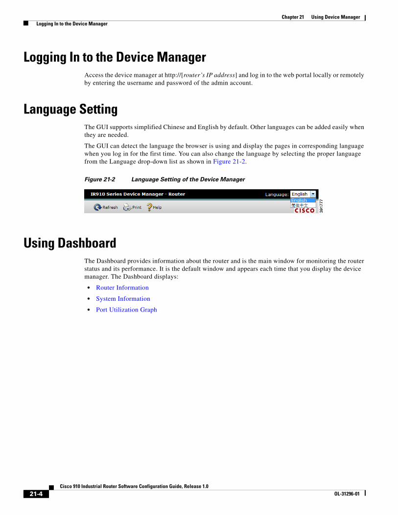
Configuring 3G USB ModemYou can configure the following 3G USB Modem settings on the router:
• Configuring 3G Settings
• Binding GSM SIM Profiles
• Managing PIN
• Switching Firmware
Configuring 3G Settings
You can search PLMN and configure 3G settings for UMTS or CDMA on the 3G Settings Tab.
• Searching Available PLMNs
• Configuring 3G Settings for UMTS
• Configuring 3G Settings for CDMA
Searching Available PLMNs
Follow the steps below to search available PLMNs.
Step 1 Click 3G USB Modem under Network Configuration in the left pane and then click 3G Settings in the right pane. The 3G Settings tab is displayed, as shown in Figure 21-19.
Figure 21-19 3G Settings
Step 2 Click Search.
Step 3 Make sure that the PIN is verified.
Step 4 Click Submit and wait several minutes.
Step 5 Complete the search operation according to the prompt information.
21-23Cisco 910 Industrial Router Software Configuration Guide, Release 1.0
OL-31296-01

Chapter 21 Using Device Manager Configuring the Network
Configuring 3G Settings for UMTS
Follow the steps below to configure 3G settings for UMTS.
Step 1 Click 3G USB Modem under Network Configuration in the left pane and then click 3G Settings in the right pane. The 3G Settings tab is displayed, as shown in Figure 21-19.
Step 2 Choose ON or OFF from the Radio drop-down list, to turn on or turn off the radio hardware resources.
Step 3 From the Profile drop-down list, choose the profile number from 1 to 16, to configure the SIM card to use profiles for GSM.
Step 4 In the Authentication Pin field, enter a 4 to 8 character code to store the SIM CHV1 code for verification. You should input the correct PIN provided by your carrier to unlock the SIM card when you see a prompt message says “Please input the right pin.”
Step 5 Choose ON or OFF from the DDR drop-down list, to specify whether dial-on-demand routing (DDR) is supported or not.
Step 6 In the Timeout field, specify the duration of idle time in seconds. This field is only valid when DDR is On.
Step 7 Enter the name of the CHAT scrip in the Dialer String field.
Step 8 Choose NONE or CHAP from the PPP Authentication drop-down list, to specify whether PPP configuration is supported or not. If you choose CHAP, specify PPP hostname and password as well.
• PPP hostname—An interface-specific CHAP hostname used for authentication. The hostname must match the username provided by the carrier.
• PPP Password—The password required for authentication of the remote router. The password must match the password provided by the carrier.
Step 9 Choose DISABLE or ENABLE from the IP Negotiated drop-down list, to specify whether you can configure IP address and Net mask or not. When you choose DISABLE, manually enter IP address and net mask in both fields.
Step 10 Enter the name of the CHAT script in the Chat Name field, to create a script that will place a call over a modem.
Step 11 In the Expect Send field, enter a pair of information elements, which contains an item to expect and an item to send in response.
Step 12 Choose one of the following bands from the Band drop-down list:
• Auto-Band
• GSM-All-Bands
• WCDMA-All-Bands
Step 13 Choose AUTO or MANUAL from the PLMN Select drop-down list, to automatically or manually select from the available public land mobile network (PLMN) to attach. If you select MANUAL, you must select one of the available technologies from the list of PLMNs.
Step 14 Click Submit.
21-24Cisco 910 Industrial Router Software Configuration Guide, Release 1.0
OL-31296-01

Chapter 21 Using Device Manager Configuring the Network
Configuring 3G Settings for CDMA
Follow the steps below to configure 3G settings for CDMA.
Step 1 Click 3G USB Modem under Network Configuration in the left pane and then click 3G Settings in the right pane. The 3G Settings tab is displayed, as shown in Figure 21-19.
Step 2 Choose ON or OFF from the Radio drop-down list, to turn on or turn off the radio hardware resources.
Step 3 In the Authentication pin field, enter a 4 to 8 character code to store the SIM CHV1 code for verification. You should input the correct PIN provided by your carrier to unlock the SIM card when you see a prompt message says “Please input the right pin.”
Step 4 Choose ON or OFF from the DDR drop-down list, to specify whether dial-on-demand routing (DDR) is supported or not.
Step 5 In the Timeout field, specify the duration of idle time in seconds. This field is only valid when DDR is On.
Step 6 Enter the name of the CHAT scrip in the Dialer String field.
Step 7 Choose NONE or CHAP from the PPP Authentication drop-down list, to specify whether PPP configuration is supported or not. If you choose CHAP, specify PPP hostname and password as well.
• PPP hostname—An interface-specific CHAP hostname used for authentication. The hostname must match the username provided by the carrier.
• PPP Password—The password required for authentication of the remote router. The password must match the password provided by the carrier.
Step 8 Choose DISABLE or ENABLE from the IP Negotiated drop-down list, to specify whether you can configure IP address and Net mask. When you choose DISABLE, manually enter IP address and net mask in both fields.
Step 9 Enter the name of the CHAT script in the Chat Name field, to create a script that will place a call over a modem.
Step 10 In the Expect Send field, enter a pair of information elements, which contains an item to expect and an item to send in response.
Step 11 Choose one of the following modes from the Cellular Mode drop-down list:
• 1xRTT
• 1xEVDO
• hybrid
Step 12 Click Submit.
Binding GSM SIM Profiles
Follow the steps below to bind GSM SIM profiles.
Note The CDMA profile tab cannot be edit. It is only used to display the information.
Step 1 Click 3G USB Modem under Network Configuration in the left pane and then click Profile in the right pane. The Profile tab is displayed, as shown in Figure 21-20.
21-25Cisco 910 Industrial Router Software Configuration Guide, Release 1.0
OL-31296-01

Chapter 21 Using Device Manager Configuring the Network
Figure 21-20 3G Profiles
Step 2 Click Create in Profile binding field, the Profile Binding Table will add a row. You can click Modify or Remove if you want to modify or delete that row. You can assign one profile ID to a SIM profile.
Step 3 In the Profile Id field, enter the ID of the profile.
Step 4 Enter the Access Point Name (APN) in the APN field.
Step 5 Choose CHAP, PAP, or None from the Authentication drop-down list.
Step 6 Enter the user name and password required for authentication.
Step 7 From the Protocol drop-down list, choose IPv4, IPv6, IPv4v6, or PPP.
Step 8 Click Submit.
Managing PIN
You can use the PIN tab to change the PIN, lock or unlock the PIN, and unblock a PIN.
Follow the steps below to manage the PIN:
Step 1 Click 3G USB Modem under Network Configuration in the left pane and then click PIN in the right pane. The PIN tab is displayed, as shown in Figure 21-21.
21-26Cisco 910 Industrial Router Software Configuration Guide, Release 1.0
OL-31296-01

Chapter 21 Using Device Manager Configuring the Network
Figure 21-21 Managing PIN
Step 2 Choose the option that you want and click Submit.
Switching Firmware
Follow the steps below to switch the firmware:
Step 1 Click 3G USB Modem under Network Configuration in the left pane and then click Firmware in the right pane. The Firmware tab is displayed, as shown in Figure 21-22.
Figure 21-22 Switching Firmware
Step 2 Choose the firmware that you want and click Switch.
Configuring PPPoEYou can configure the following PPPoE settings on the router:
• Adding a PPPoE Profile
• Editing a PPPoE Profile
21-27Cisco 910 Industrial Router Software Configuration Guide, Release 1.0
OL-31296-01

Chapter 21 Using Device Manager Configuring the Network
• Connecting or Disconnecting a PPPoE
• Deleting a PPPoE Profile
Adding a PPPoE Profile
Follow these steps to add a PPPoE profile:
Step 1 Click PPPoE under Network Configuration in the left pane. The PPPoE window is displayed, as shown in Figure 21-23.
Figure 21-23 PPPoE Configuration
Step 2 Click Add to add a row in the profile table. The Create PPPoE window is displayed, as shown in Figure 21-24.
Figure 21-24 Add PPPoE Profile
Step 3 Enter the following values to create the PPPoE profile:
• Profile Name—Specify the PPPoE profile name.
• Dial-Pool—Specify the dialing pool for PPPoE.
• Dialer Interface—Specify Dialer interface number for PPPoE.
21-28Cisco 910 Industrial Router Software Configuration Guide, Release 1.0
OL-31296-01

Chapter 21 Using Device Manager Configuring the Network
• PPP Chap Hostname—Specify an interface-specific CHAP hostname.
• PPP Chap Password—Specify an interface-specific CHAP password.
Step 4 Click OK to add the new profile.
Editing a PPPoE Profile
Follow these steps to edit a PPPoE profile:
Step 1 Click PPPoE under Network Configuration in the left pane.
Step 2 Choose a profile from the list and click Edit. The Edit Profile window is displayed, with the same options with the Add Profile window.
Step 3 Make the changes that you want.
Step 4 Click OK to save the changes.
Connecting or Disconnecting a PPPoE
Follow these steps to connect to or disconnect from a PPPoE connection:
Step 1 Click PPPoE under Network Configuration in the left pane.
Step 2 Choose an profile in the list and click Connect or Disconnect.
Deleting a PPPoE Profile
Follow these steps to delete a PPPoE profile:
Step 1 Click PPPoE under Network Configuration in the left pane.
Step 2 Choose an profile in the list and click Delete to delete that row.
Configuring VLANYou can configure the following VLAN settings on the router:
• Creating VLANs
• Deleting VLANs
• Configuring Port and VLAN Membership
21-29Cisco 910 Industrial Router Software Configuration Guide, Release 1.0
OL-31296-01
Chapter 21 Using Device Manager Configuring the Network
Creating VLANs
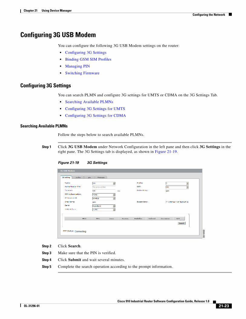
Follow these steps to create a VLAN:
Step 1 Click VLAN under Network Configuration in the left pane. The Configure Ports tab is displayed, as shown in Figure 21-25.
Figure 21-25 VLAN Ports Settings
Step 2 Click Configure VLANs tab to display the VLAN Configuration.
Step 3 Click the Create button. The Create VLAN window is displayed, as shown in Figure 21-26.
Figure 21-26 VLAN Settings–Creating VLAN
Step 4 Enter VLAN ID.
Step 5 Click OK to create the VLAN.
Deleting VLANs
Follow these steps to delete a VLAN:
21-30Cisco 910 Industrial Router Software Configuration Guide, Release 1.0
OL-31296-01

Chapter 21 Using Device Manager Configuring the Network
Step 1 Click VLAN under Network Configuration in the left pane. The VLAN settings window is displayed, as shown in Figure 21-23.
Step 2 Click Configure VLANs to display the VLAN Configuration.
Step 3 Choose a VLAN from the list and click Delete to delete that row.
Configuring Port and VLAN Membership
Follow these steps to configure the VLAN setting of the port:
Step 1 Click VLAN under Network Configuration in the left pane. The Configure Ports tab is displayed, as shown in Figure 21-25.
Step 2 Choose the port and click Modify. The Modify ports window is displayed, as shown in Figure 21-27.
Figure 21-27 Modify Ports
Step 3 Choose the port mode, access or trunk.
Step 4 If you choose access mode, enter access VLAN ID; If you choose trunk, choose trunking mode, configure allowed VLAN and native VLAN.
Step 5 Click OK to save the changes and Cancel to restore the previous values.
Configuring VPNThe router supports the following types of VPN connections:
• PPTP
• IPSEC
• L2TP
21-31Cisco 910 Industrial Router Software Configuration Guide, Release 1.0
OL-31296-01

Chapter 21 Using Device Manager Configuring the Network
To add, edit, and remove a VPN connection, or connect to a VPN, click VPN in the left pane. The VPN information window is displayed in the right pane.
• Adding a VPN connection
• Connecting a VPN Connection
• Disconnecting a VPN Connection
• Deleting a VPN Connection
Adding a VPN connection
To add a VPN connection of PPTP type, follow these steps:
Step 1 Click VPN in the left pane under Network Configuration. The VPN window is displayed, as shown in Figure 21-28.
Figure 21-28 VPN Settings
Step 2 Click Add in the right pane. A new window is displayed, as shown in Figure 21-29.
21-32Cisco 910 Industrial Router Software Configuration Guide, Release 1.0
OL-31296-01
Chapter 21 Using Device Manager Configuring the Network
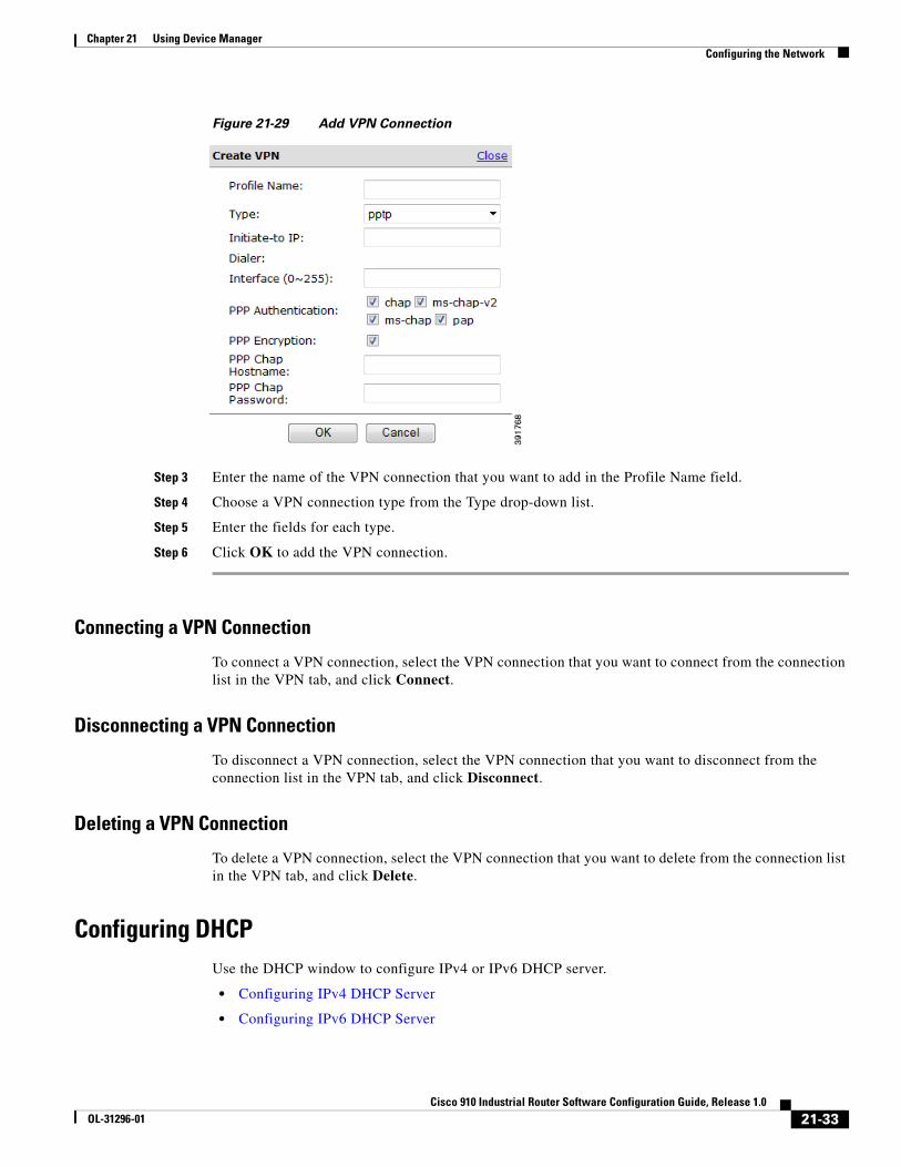
Figure 21-29 Add VPN Connection
Step 3 Enter the name of the VPN connection that you want to add in the Profile Name field.
Step 4 Choose a VPN connection type from the Type drop-down list.
Step 5 Enter the fields for each type.
Step 6 Click OK to add the VPN connection.
Connecting a VPN Connection
To connect a VPN connection, select the VPN connection that you want to connect from the connection list in the VPN tab, and click Connect.
Disconnecting a VPN Connection
To disconnect a VPN connection, select the VPN connection that you want to disconnect from the connection list in the VPN tab, and click Disconnect.
Deleting a VPN Connection
To delete a VPN connection, select the VPN connection that you want to delete from the connection list in the VPN tab, and click Delete.
Configuring DHCPUse the DHCP window to configure IPv4 or IPv6 DHCP server.
• Configuring IPv4 DHCP Server
• Configuring IPv6 DHCP Server
21-33Cisco 910 Industrial Router Software Configuration Guide, Release 1.0
OL-31296-01

Chapter 21 Using Device Manager Configuring the Network
Configuring IPv4 DHCP Server
Follow these steps to configure the IPv4 DHCP server:
Step 1 Click DHCP in the left pane under Network Configuration. The DHCP window is displayed, as shown in Figure 21-30.
Figure 21-30 DHCP Settings
Step 2 Check Enable IPv4 DHCP Server to enable the IPv4 DHCP Server.
Step 3 Enter the IP address of the server in the Network field and choose the netmask.
Step 4 Enter the DHCP pool range in Range and to fields.
Step 5 Enter the Domain Name, DNS Server and the Default Router if you want.
Step 6 Click Submit to save the changes and Clear to discard the unsaved changes.
Configuring IPv6 DHCP Server
Follow these steps to configure the IPv6 DHCP server:
Step 1 Click DHCP in the left pane under Network Configuration. The DHCP window is displayed, as shown in Figure 21-30.
Step 2 Check Enable IPv6 DHCP Server to enable the IPv6 DHCP Server.
Step 3 Enter the address prefix for address assignment in the Address Prefix field.
Step 4 Enter the DHCP pool range in Range and to fields.
Step 5 Enter the Domain Name and DNS Server if you want.
Step 6 Click Submit to save the changes and Clear to discard the unsaved changes.
21-34Cisco 910 Industrial Router Software Configuration Guide, Release 1.0
OL-31296-01

Chapter 21 Using Device Manager Configuring Platform Settings
Configuring NATFollow these steps to configure NAT on the router:
Step 1 Click NAT in the left pane under Network Configuration. The NAT window is displayed, as shown in Figure 21-31.
Figure 21-31 NAT Configuration
Step 2 Check Enable NAT to enable the NAT on the router.
Step 3 Choose the inside interface. If you choose a VLAN interface, make sure there is at least one VLAN exists.
Step 4 Enter the IP address and subnet mask of the inside interface.
Step 5 Choose one of the following as the outside interface:
• GigabitEthernet—GigabitEthernet interface.
• Dialer—If you choose a dialer interface, make sure there is at least one dialer interface exists.
• Dot11 radio—Wi-Fi interface. Only available for the model IR910W-K9.
• Cellular—3G interface. Only available for the model IR910G-K9.
Step 6 Enter the IP address and subnet mask of the outside interface.
Step 7 Click Submit to save the changes and Clear to discard the unsaved changes.
Configuring Platform SettingsPlatform configuration includes the following information:
• Configuring Ports
• Configuring SNMP
• Configuring Authentication, Authorization, and Accounting
• Configuring Time
• Configuring HTTPS
21-35Cisco 910 Industrial Router Software Configuration Guide, Release 1.0
OL-31296-01
Chapter 21 Using Device Manager Configuring Platform Settings
• Displaying TDR Results
Configuring LLDPUse the LLDP window to configure LLDP settings and neighbors:
• Configuring LLDP Settings
• Displaying LLDP Neighbors
Configuring LLDP Settings
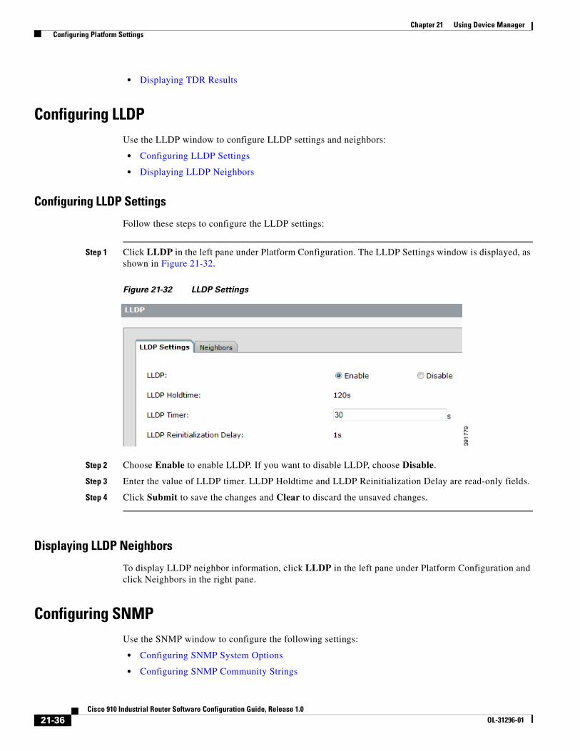
Follow these steps to configure the LLDP settings:
Step 1 Click LLDP in the left pane under Platform Configuration. The LLDP Settings window is displayed, as shown in Figure 21-32.
Figure 21-32 LLDP Settings
Step 2 Choose Enable to enable LLDP. If you want to disable LLDP, choose Disable.
Step 3 Enter the value of LLDP timer. LLDP Holdtime and LLDP Reinitialization Delay are read-only fields.
Step 4 Click Submit to save the changes and Clear to discard the unsaved changes.
Displaying LLDP Neighbors
To display LLDP neighbor information, click LLDP in the left pane under Platform Configuration and click Neighbors in the right pane.
Configuring SNMPUse the SNMP window to configure the following settings:
• Configuring SNMP System Options
• Configuring SNMP Community Strings
21-36Cisco 910 Industrial Router Software Configuration Guide, Release 1.0
OL-31296-01
Chapter 21 Using Device Manager Configuring Platform Settings
• Configuring SNMP Views
• Configuring SNMP Groups
• Configuring SNMP Users
Configuring SNMP System Options
Follow these steps to configure SNMP system options:
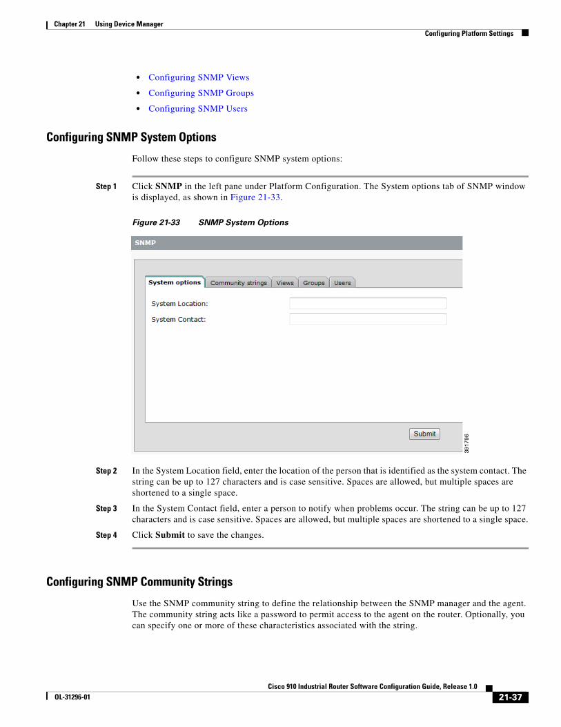
Step 1 Click SNMP in the left pane under Platform Configuration. The System options tab of SNMP window is displayed, as shown in Figure 21-33.
Figure 21-33 SNMP System Options
Step 2 In the System Location field, enter the location of the person that is identified as the system contact. The string can be up to 127 characters and is case sensitive. Spaces are allowed, but multiple spaces are shortened to a single space.
Step 3 In the System Contact field, enter a person to notify when problems occur. The string can be up to 127 characters and is case sensitive. Spaces are allowed, but multiple spaces are shortened to a single space.
Step 4 Click Submit to save the changes.
Configuring SNMP Community Strings
Use the SNMP community string to define the relationship between the SNMP manager and the agent. The community string acts like a password to permit access to the agent on the router. Optionally, you can specify one or more of these characteristics associated with the string.
21-37Cisco 910 Industrial Router Software Configuration Guide, Release 1.0
OL-31296-01

Chapter 21 Using Device Manager Configuring Platform Settings
Adding SNMP Community Strings
Follow these steps to add an SNMP community string:
Step 1 Click SNMP in the left pane under Platform Configuration and click Community strings in the right pane. The Community strings tab of SNMP window is displayed, as shown in Figure 21-34.
Figure 21-34 SNMP Community Strings
Step 2 Click Add to open the Add Community Strings window, as shown in Figure 21-35.
Figure 21-35 Add SNMP Community String
Step 3 Enter a string in the Community String field.
Step 4 Choose RO or RW for the Community Type option. Specify read-only (RO) if you want authorized management stations to retrieve MIB objects; Specify read-write (RW) if you want authorized management stations to retrieve and modify MIB objects. By default, the community string permits read-only access to all objects.
Step 5 Click Add to add the community string.
21-38Cisco 910 Industrial Router Software Configuration Guide, Release 1.0
OL-31296-01

Chapter 21 Using Device Manager Configuring Platform Settings
Deleting SNMP Community Strings
Follow these steps to delete an SNMP community string:
Step 1 Click SNMP in the left pane under Platform Configuration and click Community strings in the right pane. The Community strings tab of SNMP window is displayed, as shown in Figure 21-34.
Step 2 Choose the line that you want to delete and click Delete.
Configuring SNMP Views
To restrict a group of users to view a specific MIB tree, you must create an SNMP view using the device manager. Once you create the view, you need to create an SNMP group and SNMP users that belong to this group as described in later sections.
Views are listed in the order in which they have been created. You can create up to 10 views.
Adding SNMP Views
Follow these steps to add SNMP views:
Step 1 Click SNMP in the left pane under Platform Configuration and click Views in the right pane. The Views tab of SNMP window is displayed, as shown in Figure 21-36.
Figure 21-36 SNMP Views
Step 2 Click Add to open the Add View window, as shown in Figure 21-37.
21-39Cisco 910 Industrial Router Software Configuration Guide, Release 1.0
OL-31296-01

Chapter 21 Using Device Manager Configuring Platform Settings
Figure 21-37 Add SNMP View
Step 3 Enter a name in the View Name field.
Step 4 Enter the object identifier in the OID Tree field. This value identifies a subtree of the MIB. It can be up to 64 alphanumeric characters.
Step 5 Choose a type for the Type of View option.
• included—The MIB family is included in the view.
• excluded—The MIB family is excluded from the view.
Step 6 Click OK to add the community string.
Deleting SNMP Views
Follow these steps to delete an SNMP view:
Step 1 Click SNMP in the left pane under Platform Configuration and click Views in the right pane. The Views tab of SNMP window is displayed, as shown in Figure 21-36.
Step 2 Choose the line that you want to delete and click Delete.
Configuring SNMP Groups
You must set up an SNMP group if you are going to create any SNMP users or want to restrict a group of users to view a specific MIB subtree.
Groups are listed in the order in which they have been created. The maximum number of SNMP groups that can be created is 10.
Adding SNMP Groups
Follow these steps to add SNMP groups:
21-40Cisco 910 Industrial Router Software Configuration Guide, Release 1.0
OL-31296-01

Chapter 21 Using Device Manager Configuring Platform Settings
Step 1 Click SNMP in the left pane under Platform Configuration and click Groups in the right pane. The Groups tab of SNMP window is displayed, as shown in Figure 21-38.
Figure 21-38 SNMP Groups
Step 2 Click Add to open the Add Group window, as shown in Figure 21-37.
Figure 21-39 Add SNMP Group
Step 3 Enter a name in the Group Name field.
Step 4 Choose a security version from the Version drop-down list. Valid values are:
• v1—Version 1 security model (SNMP Version 1 [noAuthNoPriv]).
• v2c—Version 2c security model (SNMP Version 2 [noAuthNoPriv]).
• v3-auth—User security level (SNMP Version 3 [AuthNoPriv]).
• v3-noauth—User security level (SNMP Version 3 [noAuthNoPriv]).
• v3-priv—User security level (SNMP Version 3 [AuthPriv]).
Step 5 Choose Readview and Writerview.
21-41Cisco 910 Industrial Router Software Configuration Guide, Release 1.0
OL-31296-01

Chapter 21 Using Device Manager Configuring Platform Settings
Step 6 Click OK to add the group.
Deleting SNMP Groups
Follow these steps to delete an SNMP group:
Step 1 Click SNMP in the left pane under Platform Configuration and click Groups in the right pane. The Groups tab of SNMP window is displayed, as shown in Figure 21-38.
Step 2 Choose the line that you want to delete and click Delete.
Configuring SNMP Users
Users are listed in the order in which they have been created. The maximum number of users that can be created is 10. Before you add users, make sure there is at least one group that has already been created.
Adding SNMP Groups
Follow these steps to add SNMP groups:
Step 1 Click SNMP in the left pane under Platform Configuration and click Groups in the right pane. The Users tab of SNMP window is displayed, as shown in Figure 21-40.
Figure 21-40 SNMP Users
Step 2 Click Add to open the Add User window, as shown in Figure 21-41.
21-42Cisco 910 Industrial Router Software Configuration Guide, Release 1.0
OL-31296-01

Chapter 21 Using Device Manager Configuring Platform Settings
Figure 21-41 Add SNMP User
Step 3 Enter a name in the User Name drop-down list.
Step 4 Choose a group from the Group Name field.
Step 5 Choose a security version from the Version drop-down list. Valid values are v1, v2c, and v3. If you choose v3, enter the values in the Auth, Auth-password, Priv, and Prov-password fields as well.
Step 6 Click OK to add the group.
Deleting SNMP Users
Follow these steps to delete an SNMP user:
Step 1 Click SNMP in the left pane under Platform Configuration and click Users in the right pane. The Users tab of SNMP window is displayed, as shown in Figure 21-38.
Step 2 Choose the line that you want to delete and click Delete.
Configuring Authentication, Authorization, and AccountingThe router supports local authentication using the local lookup database or remote authentication using one or more RADIUS servers. Use the AAA window to configure the authentication.
• Configuring Authentication Type
• Configuring RADIUS Server List
• Configuring RADIUS Group List
• Configuring Local Authentication
Configuring Authentication Type
Follow these steps to configure authentication type:
21-43Cisco 910 Industrial Router Software Configuration Guide, Release 1.0
OL-31296-01
Chapter 21 Using Device Manager Configuring Platform Settings
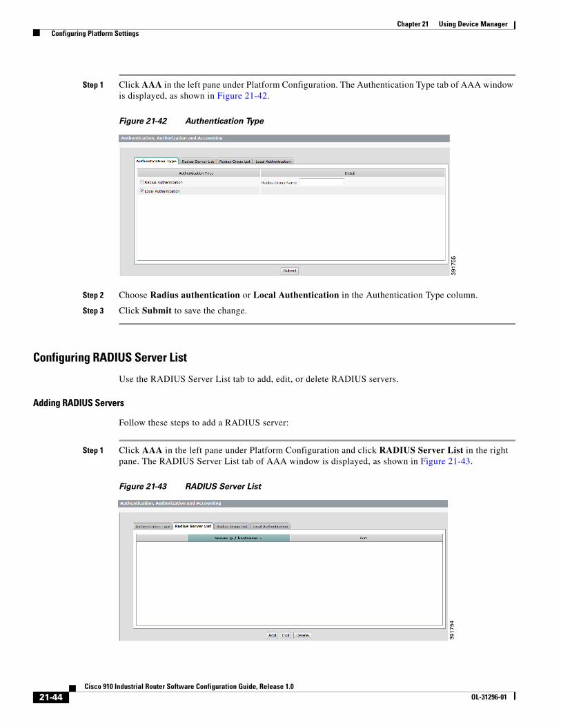
Step 1 Click AAA in the left pane under Platform Configuration. The Authentication Type tab of AAA window is displayed, as shown in Figure 21-42.
Figure 21-42 Authentication Type
Step 2 Choose Radius authentication or Local Authentication in the Authentication Type column.
Step 3 Click Submit to save the change.
Configuring RADIUS Server List
Use the RADIUS Server List tab to add, edit, or delete RADIUS servers.
Adding RADIUS Servers
Follow these steps to add a RADIUS server:
Step 1 Click AAA in the left pane under Platform Configuration and click RADIUS Server List in the right pane. The RADIUS Server List tab of AAA window is displayed, as shown in Figure 21-43.
Figure 21-43 RADIUS Server List
21-44Cisco 910 Industrial Router Software Configuration Guide, Release 1.0
OL-31296-01

Chapter 21 Using Device Manager Configuring Platform Settings
Step 2 Click Add to open the Add RADIUS Server window, as shown in Figure 21-44.
Figure 21-44 Add RADIUS Server
Step 3 Enter the domain name or IP address of the RADIUS server in the server ip/name field.
Step 4 Enter the UDP destination port for authentication requests in the server port field.
Step 5 Specifies the authentication and encryption key for all RADIUS communications between the router and the RADIUS server in the key field. This key must match the encryption used on the RADIUS daemon. All leading spaces are ignored, but spaces within and at the end of the key are used. If you use spaces in your key, do not enclose the key in quotation marks unless the quotation marks themselves are part of the key.
Step 6 Enter the value in the key field again in the key confirm field.
Step 7 Click OK to add the RADIUS server.
Deleting RADIUS Servers
Follow these steps to delete a RADIUS server:
Step 1 Click AAA in the left pane under Platform Configuration and click RADIUS Server List in the right pane. The RADIUS Server List tab of AAA window is displayed, as shown in Figure 21-43.
Step 2 Choose the line that you want to delete from the RADIUS server list and click Delete.
Configuring RADIUS Group List
Use the RADIUS Group List tab to add, edit, or delete RADIUS groups.
Adding RADIUS Groups
Follow these steps to add a RADIUS group:
21-45Cisco 910 Industrial Router Software Configuration Guide, Release 1.0
OL-31296-01

Chapter 21 Using Device Manager Configuring Platform Settings
Step 1 Click AAA in the left pane under Platform Configuration and click RADIUS Group List in the right pane. The RADIUS Group List tab of AAA window is displayed, as shown in Figure 21-45.
Figure 21-45 RADIUS Group List
Step 2 Click Add to open the Add RADIUS Group window, as shown in Figure 21-46.
Figure 21-46 Add RADIUS Group
Step 3 Enter a name in the group name field.
Step 4 Enter the IP address or domain name of the server in the server field.
Step 5 Enter the UDP destination port for authentication requests in the server auth-port field.
Step 6 Click OK to add the RADIUS group.
Deleting RADIUS Groups
Follow these steps to delete a RADIUS group:
21-46Cisco 910 Industrial Router Software Configuration Guide, Release 1.0
OL-31296-01

Chapter 21 Using Device Manager Configuring Platform Settings
Step 1 Click AAA in the left pane under Platform Configuration and click RADIUS Group List in the right pane. The RADIUS Group List tab of AAA window is displayed, as shown in Figure 21-45.
Step 2 Choose the line that you want to delete from the RADIUS group list and click Delete group.
Configuring Local Authentication
Use the Local Authentication tab to add or delete local users.
Adding Local Users
Follow these steps to add a local authentication user:
Step 1 Click AAA in the left pane under Platform Configuration and click Local Authentication in the right pane. The Local Authentication tab of AAA window is displayed, as shown in Figure 21-47.
Figure 21-47 Local Authentication
Step 2 Click Add to open the Add local user window, as shown in Figure 21-48.
21-47Cisco 910 Industrial Router Software Configuration Guide, Release 1.0
OL-31296-01

Chapter 21 Using Device Manager Configuring Platform Settings
Figure 21-48 Add Local User
Step 3 Enter user name, password, and description of the user, and repeat the password in the confirm password field.
Step 4 Click OK to add the local user.
Deleting Local Users
Follow these steps to delete a local user:
Step 1 Click AAA in the left pane under Platform Configuration and click Local Authentication in the right pane. The Local Authentication tab of AAA window is displayed, as shown in Figure 21-43.
Step 2 Choose the line that you want to delete from the list and click Delete.
Configuring TimeThe router allows you to perform time synchronization using Network Time Protocol (NTP) or set time manually. You can configure either way in this window:
• Configuring NTP Server
• Configuring NTP Key
• Configuring Time Manually
Configuring NTP Server
Use the NTP Server tab to add, edit, or delete NTP servers.
Adding NTP Servers
Follow these steps to add a NTP server:
21-48Cisco 910 Industrial Router Software Configuration Guide, Release 1.0
OL-31296-01

Chapter 21 Using Device Manager Configuring Platform Settings
Step 1 Click Time in the left pane under Platform Configuration. The NTP Server tab of Time window is displayed.
Step 2 Click Add to open the Add NTP Server window, as shown in Figure 21-49.
Figure 21-49 Add NTP Server
Step 3 Enter the IP address of the NTP server in the Server Address field.
Step 4 Choose the server address type:
• IP address
• hostname(V4)
• hostname(V6)
Step 5 Enter the key number in the Key Number field.
Step 6 (Optional) Enter the maximum polling time interval in seconds in the Maxpoll field.
Step 7 (Optional) Enter the minimum polling time interval in seconds in the Minpoll field.
Step 8 Click OK to add the NTP server.
Deleting NTP Servers
Follow these steps to delete a NTP server:
Step 1 Click Time in the left pane under Platform Configuration. The NTP Server tab of Time window is displayed.
Step 2 Choose the line that you want to delete from the NTP server list and click Delete.
21-49Cisco 910 Industrial Router Software Configuration Guide, Release 1.0
OL-31296-01

Chapter 21 Using Device Manager Configuring Platform Settings
Configuring NTP Key
Use the NTP Key tab to add, edit, or delete NTP Keys.
Adding NTP Keys
Follow these steps to add a NTP key:
Step 1 Click Time in the left pane under Platform Configuration and click NTP Key in the right pane. The NTP Key tab of Time window is displayed, as shown in Figure 21-50.
Figure 21-50 NTP Key
Step 2 Click Add to open the Add NTP Key window, as shown in Figure 21-51.
Figure 21-51 Add NTP Key
Step 3 Enter the key number in the Key Number field. The key number is an unsigned 32 bit integer.
Step 4 Enter the key value in the Key Value field. The key value is an 8-character ASCII string.
Step 5 Confirm the key value.
Step 6 Check Trusted if this key value is to be trusted.
21-50Cisco 910 Industrial Router Software Configuration Guide, Release 1.0
OL-31296-01

Chapter 21 Using Device Manager Configuring Platform Settings
Step 7 Click OK to add the NTP key.
Deleting NTP Keys
Follow these steps to delete a NTP key:
Step 1 Click Time in the left pane under Platform Configuration and click NTP Key in the right pane. The NTP Key tab of Time window is displayed, as shown in Figure 21-50.
Step 2 Choose the line that you want to delete from the NTP key list and click Delete.
Configuring Time Manually
In addition to configure the system time by NTP servers, you can configure the time manually using the Clock tab and Timezone tab.
Configuring System Clock
Follow these steps to configure local system time:
Step 1 Click Time in the left pane under Platform Configuration and click Clock in the right pane. The Clock tab of Time window is displayed, as shown in Figure 21-52.
Figure 21-52 Configuring Time Manually
Step 2 Enter values in the Year, Month, Day, Hour, Minute, and Second fields.
Step 3 Click Submit to save the time.
Configuring Time Zone
Follow these steps to configure time zone for the local time:
21-51Cisco 910 Industrial Router Software Configuration Guide, Release 1.0
OL-31296-01

Chapter 21 Using Device Manager Configuring Platform Settings
Step 1 Click Time in the left pane under Platform Configuration and click Timezone in the right pane. The Timezone tab of Time window is displayed, as shown in Figure 21-53.
Figure 21-53 Time Zone Setting
Step 2 Enter a time zone value in the Time Zone field.
Step 3 Click Submit to save the time zone setting.
Configuring HTTPSFollow these steps to enable HTTPS on the router:
Step 1 Click HTTPS in the left pane under Platform Configuration. The HTTPS window is displayed, as shown in Figure 21-54.
Figure 21-54 HTTPS Setting
Step 2 Check Enable https to enable the HTTPS function on the router.
Step 3 In the HTTPS port field, enter the port number to be used for the HTTPS server. The default port number is 443. Valid options are 443 or any number in the range 1025 to 65535.
Step 4 Click Submit to save the changes.
21-52Cisco 910 Industrial Router Software Configuration Guide, Release 1.0
OL-31296-01

Chapter 21 Using Device Manager Monitoring the Status of System and Network
Displaying TDR ResultsThe router allows you to show Time-Domain Reflectometer (TDR) test results for an interface.
Follow these steps to display TDR results:
Step 1 Click TDR in the left pane under Platform Configuration.
Step 2 Choose an interface from the Interface drop-down list.
Step 3 Click the Test button on the right of the Interface drop-down list. The TDR results are displayed, as shown in Figure 21-55.
Figure 21-55 TDR Results
Monitoring the Status of System and NetworkYou can monitor the status of the router system and the network using the Monitor menus.
• Viewing the Front Panel
• Monitoring the System
• Monitoring Port Status
• Monitoring Port Statistics
• Viewing MAC-Address Table
• Viewing DHCP or DHCPv6 Binding Table
• Viewing Logs
• Monitoring 3G Information
• Viewing PPPoE Statistics
21-53Cisco 910 Industrial Router Software Configuration Guide, Release 1.0
OL-31296-01

Chapter 21 Using Device Manager Monitoring the Status of System and Network
• Monitoring NAT Status
Viewing the Front PanelThe Front Panel view is a graphical display of the router front panel. Click Overview under Monitor in the left pane. The Front Panel View is displayed, as shown in Figure 21-56.
Figure 21-56 Front Panel View
The Uptime field shows how long the router has been operating since it was last powered on or was restarted. Status is automatically refreshed every 60 seconds or when you click Refresh. The refresh counter shows the number of seconds that remain before the next refresh cycle starts.
The router components on the Front Panel view are color-coded by status. The colors help you to quickly see if a fault or an error condition exists. Table 21-4 describes the meanings of the colors.
Table 21-4 LED Definition
LED Color Meaning
SYS Off System is not powered on or CPU has not completed boot up.
Solid green System is operating normally.
Solid red System is not functioning properly.
VPN Off VPN is not set up.
Solid green VPN is operating normally.
Solid red VPN is not functioning properly.
COM1/COM2 Off COM port is enabled and is configured as RS232 port.
Solid green COM port is enabled and is configured as RS485 port.
Solid red Not defined.
Wi-Fi/3G Off No activity.
Solid green The connection between the router and the AP/client has been established.
GE-RJ-45/GE-SFP
Off No link.
Solid green Port link, no activity.
21-54Cisco 910 Industrial Router Software Configuration Guide, Release 1.0
OL-31296-01

Chapter 21 Using Device Manager Monitoring the Status of System and Network
Monitoring the SystemClick System under Monitor in the left pane to monitor the system status. The System tab is displayed as shown in Figure 21-57.
The System tab shows the basic device information, system status, current VLAN and interface configurations, Wi-Fi settings, route information, and DNS settings.
The two charts in the System Information section indicate the CPU and memory usage.
Figure 21-57 System Information
DC-A/DC-B Off Power is not present on the circuit or the system is not powered up.
Solid green Power is present on the associated circuit and the router is already booted up.
SSD Off No power is provided to SSD.
Solid green Power is provided to SSD.
Table 21-4 LED Definition (continued)
LED Color Meaning
21-55Cisco 910 Industrial Router Software Configuration Guide, Release 1.0
OL-31296-01

Chapter 21 Using Device Manager Monitoring the Status of System and Network
Monitoring Port StatusIf the router has link problems, such as traffic that is not being received on a port, verify the port status, and verify that the port settings are correct. You should also verify that the settings of the port before connecting a device to it.
Click Port Status under Monitor in the left pane to monitor the port status. The Port Status tab is displayed as shown in Figure 21-58.
Figure 21-58 Port Status
click on the column headings to sort information. Click Refresh to update the information displayed. The information on this window is automatically updated at each system refresh (every 60 seconds).
Monitoring Port StatisticsThe Port Statistics window displays the statistics for data sent and received by the router ports since the router was last powered on, was restarted, or since the statistics were last cleared.
Click Port Statistics under Monitor in the left pane to monitor the port statistics. The Port Statistics tab is displayed as shown in Figure 21-59.
Figure 21-59 Port Statistics Overview
click on the column headings to sort information. Click Refresh to update the information displayed. The information on this window is automatically updated at each system refresh (every 60 seconds).
The types of statistics collected and displayed are grouped under these tabs:
• Overview Tab
• Transmit Detail Tab
• Receive Detail Tab
Overview Tab
Use this tab to display the specific numbers of error packets received on and sent from the port, which is a level of detail that is not available from the Dashboard graphs. The number of error packets can mean a duplex mismatch, incompatibilities with the port and its attached device, or faulty cables or attached devices. Any of these problems can cause slow network performance, data loss, or lack of connectivity.
The Overview tab displays these statistics:
21-56Cisco 910 Industrial Router Software Configuration Guide, Release 1.0
OL-31296-01

Chapter 21 Using Device Manager Monitoring the Status of System and Network
• The total transmit and received rate on each port.
• The total transmitted and received bandwidth usage each port.
• The total number of multicast/broadcast packets transmitted and received rate on each port.
• The total number of error packets.
Transmit Detail Tab
Use this tab to troubleshoot unusual changes in network traffic. If a port is sending an unusually high amount of traffic (such as multicast or broadcast packets), monitor the connected device to see if this traffic pattern is normal or if it could mean a problem.
The Transmit Detail tab displays these statistics:
• Unicast, multicast, and broadcast packets sent from each port.
• Detailed statistics of errors sent to each port.
Receive Detail Tab
Use this tab to troubleshoot unusual changes in network traffic. If a port is receiving an unusually high amount of traffic (such as multicast or broadcast packets), monitor the connected device to see if this traffic pattern is normal for the connected device or if it could mean a problem.
The Receive Detail Tab displays these statistics:
• Unicast, multicast, and broadcast packets received on each port.
• Detailed statistics of received errors on each port.
Viewing MAC-Address TableWhen the router receives a frame, it associates the media access control (MAC) address of the sending network device with the LAN port on which it was received. The MAC-address table consists of a MAC address, an output interface where an address was learned by the router and an ID number of a VLAN where a port is a member together with a Type.
21-57Cisco 910 Industrial Router Software Configuration Guide, Release 1.0
OL-31296-01

Chapter 21 Using Device Manager Monitoring the Status of System and Network
Click MAC-addresses Table under Monitor in the left pane to view the MAC addresses table. The Port Status tab is displayed as shown in Figure 21-60.
Figure 21-60 MAC-Address Table
Click on the column headings to sort information. Click Refresh to update the information displayed. The information on this window is automatically updated at each system refresh (every 60 seconds).
Viewing DHCP or DHCPv6 Binding TableThe DHCP Binding Table displays a list of bindings created on the DHCP server. The DHCPv6 Binding Table displays a list of bindings created on the DHCPv6 server. You can view MAC address, IP address, lease expiration, and type from these tables.
Click DHCP Binding Table or DHCPv6 Binding Table under Monitor in the left pane to view the DHCP Binding Table or DHCPv6 Binding Table. You can click on the column headings to sort the information.
Viewing LogsThe DHCP Binding Table displays a list of bindings created on the DHCP server. The DHCPv6 Binding Table displays a list of bindings created on the DHCPv6 server. You can view MAC address, IP address, lease expiration, and type from these tables.
Click Logs under Monitor in the left pane to view the system logs. You can filter the logs by choosing output modifiers:
• all
• begin
• exclude
• include
21-58Cisco 910 Industrial Router Software Configuration Guide, Release 1.0
OL-31296-01

Chapter 21 Using Device Manager Monitoring the Status of System and Network
Monitoring 3G InformationYou can monitor the 3G information by using these tabs of the Monitor -> 3G menu:
• Connection—Displays the current active connection state and data statistics.
• Hardware—Displays 3G hardware information.
• Network—Displays information about the carrier network and service.
• Profile—Displays 3G profile information.
• Radio—Displays 3G radio statistics.
• Security—Displays the SIM status and modem lock state.
Viewing PPPoE StatisticsThe PPPoE Statistics window displays the statistics information about the PPPoE interface. Click Refresh to update the information displayed. The information on this window is automatically updated at each system refresh (every 60 seconds).
The following information is displayed:
• Link encap—Link encapsulation protocol.
• Inet addr—Local IP address.
• P-t-P—Remote IP address.
• Mask—IP subnet Mask to be used by the interface.
• UP—Indicates that the PPPoE interface has been loaded
• POINTTOPOINT—Denotes that the device supports point-to-point.
• RUNNING—Indicates the interface is ready to accept data.
• ARP/NOARP—Indicates if the interface enables ARP.
• MULTICAST—Indicates this interface supports multicasting.
• MTU—Maximum transmission unit.
• Metric—Interface routing metric.
• Rx Packets—The total number of packets and error counter of received side.
• Tx Packets—The total number of packets and error counter of transmit side.
• Collisions—Network congestion counter.
• Txqueuelen—Length of the transmit queue of the interface.
• RX bytes—Total amount of data that has passed through the Ethernet interface of received side.
• TX bytes—Total amount of data that has passed through the Ethernet interface of transmit side.
Monitoring NAT StatusYou can monitor the NAT statistics and view NAT translation by using these tabs of the Monitor -> NAT Status menu:
• NAT Statistics tab—Displays Total Active Translations, Inside Interface, Inside Source, and Outside Interface.
21-59Cisco 910 Industrial Router Software Configuration Guide, Release 1.0
OL-31296-01

Chapter 21 Using Device Manager Troubleshooting
• NAT Translation tab—Displays Protocol Name, NATed Address, NAT-Host Address, and Destination Address.
TroubleshootingPing and traceroute are available as troubleshooting tool in the device manager. Click Troubleshooting in the left pane. The Troubleshooting window is displayed, as shown in Figure 21-61.
Figure 21-61 Troubleshooting Window
Follow these steps to do troubleshooting.
Step 1 Choose a troubleshooting approach: Ping or Layer 3 trace.
Step 2 Select the TCP/IP version: IPv4 or IPv6.
Step 3 Enter the destination IP or hostname in the Destination (IP Address/Hostname) field.
Step 4 Click Start to start troubleshooting. The result is displayed in the Result text area.
Maintenance of the RouterYou can perform software upgrade, configuration archive, VPN auto config, and to restart or reset the router in the Maintenance section.
• Software Upgrade
• Configuration Archive
• Restart or Reset
• Configuring VPN Auto Config
Software UpgradeYou can upgrade the router software to update the router with the latest software fixes and features.
21-60Cisco 910 Industrial Router Software Configuration Guide, Release 1.0
OL-31296-01

Chapter 21 Using Device Manager Maintenance of the Router
Note You must have access to the Internet to download router software from Cisco.com to your PC or network drive. A Cisco.com account is required to access the software images from the Cisco.com website. Until after the upgrade process completes, do not use or close this browser session and do not access the device manager from another browser session.
Follow these steps to upgrade the router software:
Step 1 Click Software Upgrade under Maintenance in the left pane. The Software Upgrade window is displayed, as shown in Figure 21-62.
Figure 21-62 Software Upgrade
Step 2 Click Upgrade Setting and the Upgrading Setting window is displayed, as shown in Figure 21-63.
Figure 21-63 Upgrade Setting
Step 3 The Upgrade Setting window displays device name and current version information. Click Browse to select an image file.
21-61Cisco 910 Industrial Router Software Configuration Guide, Release 1.0
OL-31296-01

Chapter 21 Using Device Manager Maintenance of the Router
Step 4 Click Upload to upload this image file. The upgrade image file name is displayed in the New Image Name field and upload status is displayed in the Status field.
Note You must download and use the software image in zip file format (not bin file format) to upgrade the router through the device manager.
Step 5 Click Upgrade to upgrade the router to the new image.
Note During the upgrade process, do not use or close this browser session. Do not access the device manager from another browser session.
When the upgrade process completes, a success message appears, and the router automatically restarts. It might take a few minutes for the router to restart with the new software.
Make sure that the latest software version on the router appears in the Current Version field.
If the upgrade process does not complete, an error message appears. If the upgrade process fails or does not complete, try to upgrade the router again by following the procedures above.
Configuration ArchiveUsing the Configuration Archive pane, you can download the configuration file to a local directory or to restore a configuration from a local directory, as shown in Figure 21-64.
Figure 21-64 Configuration Archive Information
To save the configuration file to a local directory, follow these steps:
Step 1 Choose Save configuration.
Step 2 Click the Download button to download the configuration file from the router.
Step 3 A file named running.cfg will be downloaded to your local drive. You can change the file name or location by clicking the Save as option.
To restore a configuration file from the local directory, follow these steps:
21-62Cisco 910 Industrial Router Software Configuration Guide, Release 1.0
OL-31296-01

Chapter 21 Using Device Manager Maintenance of the Router
Step 1 Choose Restore configuration from.
Step 2 Click Browse to select a configuration file from local drive.
Step 3 Click Apply.
Restart or ResetUsing the Restart/Reset pane, you can restart the router with its current settings, or reset the router to factory defaults, and then reboot.
Follow these steps to restart or reset the device:
Step 1 Click Restart/Reset under Administration in the left pane.
Step 2 Choose the restart or reset option.
Step 3 Click Submit to apply the change or Cancel to restore to the previous value.
Configuring VPN Auto ConfigThe VPN Auto Config window allows you to retrieve or restore the VPN configuration file, as shown in Figure 21-65.
Figure 21-65 VPN Auto Config
To retrieve the VPN configuration file to a local directory, follow these steps:
Step 1 Choose Retrieve VPN Config.
Step 2 Click the Retrieve as button to download the VPN configuration file from the router.
Step 3 A file named vpncfg.xml will be downloaded to your local drive. You can change the file name or location by clicking the Save as option.
To restore a VPN configuration file from the local directory, follow these steps:
21-63Cisco 910 Industrial Router Software Configuration Guide, Release 1.0
OL-31296-01

Chapter 21 Using Device Manager Maintenance of the Router
Step 1 Choose Restore VPN Config.
Step 2 Click Browse to select a VPN configuration file from local drive.
Step 3 Click Apply.
21-64Cisco 910 Industrial Router Software Configuration Guide, Release 1.0
OL-31296-01