Embed Size (px)
Citation preview

User’s Guide
Learn how to use your Fujitsu LifeBook A6120 notebook

ation
teness of this document; however, as guarantee the accuracy of the contents
es in the United States and other
soft Corporation in the United States
tional Association (PCMCIA) and any
ystems Incorporated in the United
n the United States and other countries.
Copyright and Trademark Inform
Fujitsu Computer Systems Corporation has made every effort to ensure the accuracy and compleongoing development efforts are continually improving the capabilities of our products, we cannotof this document. We disclaim liability for errors, omissions, or future changes.
Fujitsu, the Fujitsu logo, and LifeBook are registered trademarks of Fujitsu Limited.
Intel and Intel Core are trademarks or registered trademarks of Intel Corporation or its subsidiaricountries.
Microsoft, Windows, and Windows Vista are either registered trademarks or trademarks of Microand/or other countries.
EverNote is a registered trademark of EverNote Corporation.
The ExpressCard word mark and logo are owned by the Personal Computer Memory Card Internause of such marks by Fujitsu Computer Systems Corporation is under license.
OmniPass is a trademark of Softex, Inc.
Webcam Companion is a trademark of ArcSoft, Incorporated.
Google and Picasa are trademarks or registered trademarks of Google Incorporated.
Roxio is a trademark of Roxio, a division of Sonic Solutions.
MakeDisc, PowerDirector, and PowerDVD are trademarks of CyberLink Corp.
Adobe, Acrobat, and Acrobat Reader are either a registered trademarks or trademarks of Adobe SStates and/or other countries.
Norton and Norton Internet Security are trademarks or registered trademarks of Symantec Corp. i

tection technology that is protected by ision Corporation and other rights users. nd is intended for home and other limited assembly is prohibited.
sent of Fujitsu. No part of this publication B5FJ-6421-01EN-00
U TO LEAD, A CHEMICAL KNOWN TO EPRODUCTIVE HARM.
oration
2
ok
C Rules.
o the following two conditions: cept any interference received,
The DVD player found in some models of the LifeBook notebook incorporates copyright promethod claims of certain U.S. patents and other intellectual property rights owned by MacrovUse of this copyright protection technology must be authorized by Macrovision Corporation, aviewing uses only unless authorized by Macrovision Corporation. Reverse engineering or dis
All other trademarks mentioned herein are the property of their respective owners.
© Copyright 2007 Fujitsu Computer Systems Corporation. All rights reserved.
No part of this publication may be copied, reproduced, or translated, without prior written conmay be stored or transmitted in any electronic form without the written consent of Fujitsu.
WARNING: HANDLING THE CORD ON THIS PRODUCT WILL EXPOSE YO
THE STATE OF CALIFORNIA TO CAUSE BIRTH DEFECTS OR OTHER R
WASH HANDS AFTER HANDLING.
DECLARATION OF CONFORMITY
according to FCC Part 15
Responsible Party Name: Fujitsu Computer Systems Corp
Address: 1250 E. Arques Avenue, M/S 12Sunnyvale, CA 94085
Telephone: (408) 746-6000
Declares that product: Base Model Configuration:LifeBook A6120 notebo
Complies with Part 15 of the FC
This device complies with Part 15 of the FCC rules. Operations are subject t(1) This device may not cause harmful interference, (2) This device must acincluding interference that may cause undesired operation.

output rating of 19 VDC, with a current
educe the risk of fire, electric shock and
laundry tub, in a wet basement or near a
shock from lightning.
in a fire. They may explode. Check with
communication Line Cord.stem, be sure that the outer shield of the of cable entrance as practicable, as CATV installation, contact your service
LY REPLACED. REPLACE ONLY FACTURER. DISPOSE OF USED
WITH THE SAME TYPE AND
IMPORTANT SAFETY INSTRUCTIONS This unit requires an AC adapter to operate. Use only UL Listed I.T.E. Class II Adapters with anof 4.22 A (80 W).
When using your notebook equipment, basic safety precautions should always be followed to rinjury to persons, including the following:
• Do not use this product near water for example, near a bathtub, washbowl, kitchen sink or swimming pool.
• Avoid using the modem during an electrical storm. There may be a remote risk of electric • Do not use the modem to report a gas leak in the vicinity of the leak.• Use only the power cord and batteries indicated in this manual. Do not dispose of batteries
local codes for possible special disposal instructions.• To reduce the risk of fire, use only No. 26 AWG or larger UL Listed or CSA Certified Tele• For TV tuner use: To protect from overvoltages and transients on the Cable Distribution Sy
coaxial cable is connected to earth (grounded) at the building premise as close to the pointrequired per NEC Article 820.93, ANSI/NFPA 70: 2005. If you have questions about yourprovider.
SAVE THESE INSTRUCTIONS
For Authorized Repair Technicians Only
DANGER OF EXPLOSION IF LITHIUM (CLOCK) BATTERY IS INCORRECT
WITH THE SAME OR EQUIVALENT TYPE RECOMMENDED BY THE MANU
BATTERIES ACCORDING TO THE MANUFACTURER’S INSTRUCTION.
FOR CONTINUED PROTECTION AGAINST RISK OF FIRE, REPLACE ONLY
RATING FUSE.
+AC adapter output polarity:

er amount of time; this is a natural sh one*. If you replace it, it is important se environmental damage if disposed of
he services of the Rechargeable Battery dedicated to protecting our environment
United States and Canada. To find the
ducation Initiative website
ffort to protect it for current and future
t www.shopfujitsu.com in the US or
ing; RBRC is in no way affiliated with
ECYCLED OR DISPOSED OF
5 - IMPORTANT SAFETY INSTRUCTIONS
System Disposal
Recycling your battery
Over time, the batteries that run your mobile computer will begin to hold a charge for a shortoccurrence for all batteries. When this occurs, you may want to replace the battery with a frethat you dispose of the old battery properly because batteries contain materials that could cauimproperly.
Fujitsu is very concerned with environmental protection, and has enlisted tRecycling Corporation (RBRC)**, a non-profit public service organizationby recycling old batteries at no cost to you.
RBRC has drop-off points at tens of thousands of locations throughout thelocation nearest you, go to www.RBRC.org or call 1-800-822-8837.
If there are no convenient RBRC locations near you, you can also go to the EIA Consumer E(http://EIAE.org/) and search for a convenient disposal location.
Remember – protecting the environment is a cooperative effort, and you should make every egenerations.
* To order a new battery for your Fujitsu mobile computer, go to the Fujitsu shopping site awww.fujitsu.ca/products/notebooks in Canada.
** RBRC is an independent third party to which Fujitsu provides funding for battery recyclFujitsu.
LAMP(S) INSIDE THIS PRODUCT CONTAIN MERCURY AND MUST BE RACCORDING TO LOCAL, STATE, OR FEDERAL LAWS.Hg

Prefac
. 13 . 13 . 14
Chap
. 16
. 17 . 18 . 20 . 21 . 23 . 26
. 27 . 29
. 30 . 30
Contents
e
About This Guide . . . . . . . . . . . . . . . . . . . . . . . . . . . . . . . . . . . . . . . . . . . .Conventions Used in the Guide . . . . . . . . . . . . . . . . . . . . . . . . . . . . . . . .Fujitsu Contact Information . . . . . . . . . . . . . . . . . . . . . . . . . . . . . . . . . . .
ter 1 Getting to Know Your LifeBook
Overview . . . . . . . . . . . . . . . . . . . . . . . . . . . . . . . . . . . . . . . . . . . . . . . . . . .
Locating the Controls and Connectors . . . . . . . . . . . . . . . . . . . . . . . . . . .Top Components . . . . . . . . . . . . . . . . . . . . . . . . . . . . . . . . . . . . . . . . . . .Left-Side Panel Components . . . . . . . . . . . . . . . . . . . . . . . . . . . . . . . . . .Right-Side Panel Components . . . . . . . . . . . . . . . . . . . . . . . . . . . . . . . . .Back Panel Components. . . . . . . . . . . . . . . . . . . . . . . . . . . . . . . . . . . . . .Bottom Components. . . . . . . . . . . . . . . . . . . . . . . . . . . . . . . . . . . . . . . . .
Status Indicator Panel . . . . . . . . . . . . . . . . . . . . . . . . . . . . . . . . . . . . . . . . Hard Drive/Optical Drive Access Indicator . . . . . . . . . . . . . . . . . . . . . .
Keyboard . . . . . . . . . . . . . . . . . . . . . . . . . . . . . . . . . . . . . . . . . . . . . . . . . . .Using the Keyboard . . . . . . . . . . . . . . . . . . . . . . . . . . . . . . . . . . . . . . . . .

. 33 . 34 . 36 . 36
. 37 . 37
. 38 . 38 . 40 . 41
. 42 . 43
. 44 . 44 . 45 . 45 . 45 . 45
. 46 . 46 . 47 . 47 . 48 . 49 . 49
Touchpad Pointing Device . . . . . . . . . . . . . . . . . . . . . . . . . . . . . . . . . . . . . Clicking. . . . . . . . . . . . . . . . . . . . . . . . . . . . . . . . . . . . . . . . . . . . . . . . . . .Dragging . . . . . . . . . . . . . . . . . . . . . . . . . . . . . . . . . . . . . . . . . . . . . . . . . .Touchpad Control Adjustment . . . . . . . . . . . . . . . . . . . . . . . . . . . . . . . . .
Volume Control . . . . . . . . . . . . . . . . . . . . . . . . . . . . . . . . . . . . . . . . . . . . . . Controlling the Volume . . . . . . . . . . . . . . . . . . . . . . . . . . . . . . . . . . . . . .
LifeBook Application Panel/Support Button . . . . . . . . . . . . . . . . . . . . . . Launching Applications with the LifeBook Application Panel . . . . . . . .Opening the Fujitsu Support Center with the Support Button . . . . . . . . .Launching Applications with the Support Button . . . . . . . . . . . . . . . . . .
Chapter 2 Getting Started with Your LifeBook
Power Sources . . . . . . . . . . . . . . . . . . . . . . . . . . . . . . . . . . . . . . . . . . . . . . .Connecting the Power Adapters . . . . . . . . . . . . . . . . . . . . . . . . . . . . . . . .
Display Panel . . . . . . . . . . . . . . . . . . . . . . . . . . . . . . . . . . . . . . . . . . . . . . . .Opening the Display Panel . . . . . . . . . . . . . . . . . . . . . . . . . . . . . . . . . . . .Adjusting Display Panel Brightness . . . . . . . . . . . . . . . . . . . . . . . . . . . . .Using the Keyboard . . . . . . . . . . . . . . . . . . . . . . . . . . . . . . . . . . . . . . . . .Using the Power Options . . . . . . . . . . . . . . . . . . . . . . . . . . . . . . . . . . . . .Closing the Display Panel. . . . . . . . . . . . . . . . . . . . . . . . . . . . . . . . . . . . .
Starting Your LifeBook Notebook. . . . . . . . . . . . . . . . . . . . . . . . . . . . . . .Power On . . . . . . . . . . . . . . . . . . . . . . . . . . . . . . . . . . . . . . . . . . . . . . . . .Boot Sequence . . . . . . . . . . . . . . . . . . . . . . . . . . . . . . . . . . . . . . . . . . . . .Hard Disk Drive Passwords . . . . . . . . . . . . . . . . . . . . . . . . . . . . . . . . . . .BIOS Setup Utility . . . . . . . . . . . . . . . . . . . . . . . . . . . . . . . . . . . . . . . . . .Booting the System. . . . . . . . . . . . . . . . . . . . . . . . . . . . . . . . . . . . . . . . . .Starting Windows Vista the first time . . . . . . . . . . . . . . . . . . . . . . . . . . .

51 51 51
52 52 52 54 54 54 55
56 57 59
61 62 62 64 64 65 66
68 69 69 70 71
8
Registering Your LifeBook notebook with Fujitsu . . . . . . . . . . . . . . . . . .Installing Click Me! . . . . . . . . . . . . . . . . . . . . . . . . . . . . . . . . . . . . . . . . . .Fujitsu Driver Update Utility . . . . . . . . . . . . . . . . . . . . . . . . . . . . . . . . . . .
Power Management. . . . . . . . . . . . . . . . . . . . . . . . . . . . . . . . . . . . . . . . . . . .Power/Suspend/Resume Button . . . . . . . . . . . . . . . . . . . . . . . . . . . . . . . . .Sleep Mode . . . . . . . . . . . . . . . . . . . . . . . . . . . . . . . . . . . . . . . . . . . . . . . . .Hibernation (Save-to-Disk) Feature . . . . . . . . . . . . . . . . . . . . . . . . . . . . . .Windows Power Management . . . . . . . . . . . . . . . . . . . . . . . . . . . . . . . . . .Restarting the System . . . . . . . . . . . . . . . . . . . . . . . . . . . . . . . . . . . . . . . . .Powering Off . . . . . . . . . . . . . . . . . . . . . . . . . . . . . . . . . . . . . . . . . . . . . . .
Chapter 3 User-Installable Features
Lithium ion Battery. . . . . . . . . . . . . . . . . . . . . . . . . . . . . . . . . . . . . . . . . . . .Recharging the Batteries. . . . . . . . . . . . . . . . . . . . . . . . . . . . . . . . . . . . . . .Replacing the Battery . . . . . . . . . . . . . . . . . . . . . . . . . . . . . . . . . . . . . . . . .
Optical Drive . . . . . . . . . . . . . . . . . . . . . . . . . . . . . . . . . . . . . . . . . . . . . . . . .Media Player Software . . . . . . . . . . . . . . . . . . . . . . . . . . . . . . . . . . . . . . . .Loading Media on Your Drive . . . . . . . . . . . . . . . . . . . . . . . . . . . . . . . . . .Removing Media . . . . . . . . . . . . . . . . . . . . . . . . . . . . . . . . . . . . . . . . . . . .Emergency Optical Drive Tray Release . . . . . . . . . . . . . . . . . . . . . . . . . . .Using the Media Player Software . . . . . . . . . . . . . . . . . . . . . . . . . . . . . . . .Using Media Player on Battery Power . . . . . . . . . . . . . . . . . . . . . . . . . . . .
PC Cards/ExpressCards™. . . . . . . . . . . . . . . . . . . . . . . . . . . . . . . . . . . . . .Installing PC Cards . . . . . . . . . . . . . . . . . . . . . . . . . . . . . . . . . . . . . . . . . . .Removing PC Cards . . . . . . . . . . . . . . . . . . . . . . . . . . . . . . . . . . . . . . . . . .Installing ExpressCards . . . . . . . . . . . . . . . . . . . . . . . . . . . . . . . . . . . . . . .Removing ExpressCards. . . . . . . . . . . . . . . . . . . . . . . . . . . . . . . . . . . . . . .

. 73 . 74 . 74
. 75 . 75 . 77 . 77
. 79 . 79 . 80 . 81 . 81 . 82 . 82 . 83 . 84
. 85 . 85 . 87 . 98 . 103
. 104 . 104 . 105 . 108
9
Memory Stick/Secure Digital/xD Cards . . . . . . . . . . . . . . . . . . . . . . . . . .Installing Memory Stick/SD/xD Cards. . . . . . . . . . . . . . . . . . . . . . . . . . .Removing A Memory Stick/SD/xD Card. . . . . . . . . . . . . . . . . . . . . . . . .
Memory Upgrade Module . . . . . . . . . . . . . . . . . . . . . . . . . . . . . . . . . . . . . Installing Memory Upgrade Modules. . . . . . . . . . . . . . . . . . . . . . . . . . . .Removing a Memory Upgrade Module . . . . . . . . . . . . . . . . . . . . . . . . . .Checking the Memory Capacity . . . . . . . . . . . . . . . . . . . . . . . . . . . . . . . .
Device Ports . . . . . . . . . . . . . . . . . . . . . . . . . . . . . . . . . . . . . . . . . . . . . . . . .Modem (RJ-11) Telephone Jack. . . . . . . . . . . . . . . . . . . . . . . . . . . . . . . .Internal LAN (RJ-45) Jack . . . . . . . . . . . . . . . . . . . . . . . . . . . . . . . . . . . .Universal Serial Bus Ports . . . . . . . . . . . . . . . . . . . . . . . . . . . . . . . . . . . .Headphone Jack . . . . . . . . . . . . . . . . . . . . . . . . . . . . . . . . . . . . . . . . . . . .Microphone Jack. . . . . . . . . . . . . . . . . . . . . . . . . . . . . . . . . . . . . . . . . . . .External Video Port . . . . . . . . . . . . . . . . . . . . . . . . . . . . . . . . . . . . . . . . .IEEE 1394 Port . . . . . . . . . . . . . . . . . . . . . . . . . . . . . . . . . . . . . . . . . . . . .S-Video Out Port . . . . . . . . . . . . . . . . . . . . . . . . . . . . . . . . . . . . . . . . . . .
Chapter 4 Troubleshooting Your LifeBook
Troubleshooting. . . . . . . . . . . . . . . . . . . . . . . . . . . . . . . . . . . . . . . . . . . . . . Identifying the Problem . . . . . . . . . . . . . . . . . . . . . . . . . . . . . . . . . . . . . .Specific Problems . . . . . . . . . . . . . . . . . . . . . . . . . . . . . . . . . . . . . . . . . . .Power On Self Test Messages . . . . . . . . . . . . . . . . . . . . . . . . . . . . . . . . .Modem Result Codes . . . . . . . . . . . . . . . . . . . . . . . . . . . . . . . . . . . . . . . .
Restoring Your Pre-installed Software . . . . . . . . . . . . . . . . . . . . . . . . . . . Re-installing Individual Drivers and Applications . . . . . . . . . . . . . . . . . .Restoring the Operating System for Windows Vista Systems . . . . . . . . .Automatically Downloading Driver Updates . . . . . . . . . . . . . . . . . . . . . .

. 110 . 112 . 113 . 114 . 115 . 116 . 116 . 118
. 119 . 119 . 120 . 120 . 120 . 120 . 121 . 121 . 121 . 122 . 123 . 123 . 123 . 124 . 124 . 124 . 125
10
Chapter 5 Care and Maintenance
Caring for your LifeBook Notebook . . . . . . . . . . . . . . . . . . . . . . . . . . . . . Cleaning your LifeBook notebook . . . . . . . . . . . . . . . . . . . . . . . . . . . . . .Storing your LifeBook notebook . . . . . . . . . . . . . . . . . . . . . . . . . . . . . . .Traveling with your LifeBook notebook . . . . . . . . . . . . . . . . . . . . . . . . .Batteries . . . . . . . . . . . . . . . . . . . . . . . . . . . . . . . . . . . . . . . . . . . . . . . . . .Optional Floppy Disks and Drives . . . . . . . . . . . . . . . . . . . . . . . . . . . . . .Media Care . . . . . . . . . . . . . . . . . . . . . . . . . . . . . . . . . . . . . . . . . . . . . . . .ExpressCards . . . . . . . . . . . . . . . . . . . . . . . . . . . . . . . . . . . . . . . . . . . . . .
Chapter 6 System Specifications
Specifications . . . . . . . . . . . . . . . . . . . . . . . . . . . . . . . . . . . . . . . . . . . . . . . .Configuration Label . . . . . . . . . . . . . . . . . . . . . . . . . . . . . . . . . . . . . . . . .Microprocessor . . . . . . . . . . . . . . . . . . . . . . . . . . . . . . . . . . . . . . . . . . . . .Chipset . . . . . . . . . . . . . . . . . . . . . . . . . . . . . . . . . . . . . . . . . . . . . . . . . . .Memory. . . . . . . . . . . . . . . . . . . . . . . . . . . . . . . . . . . . . . . . . . . . . . . . . . .Video. . . . . . . . . . . . . . . . . . . . . . . . . . . . . . . . . . . . . . . . . . . . . . . . . . . . .Audio . . . . . . . . . . . . . . . . . . . . . . . . . . . . . . . . . . . . . . . . . . . . . . . . . . . .Mass Storage Device Options. . . . . . . . . . . . . . . . . . . . . . . . . . . . . . . . . .Features. . . . . . . . . . . . . . . . . . . . . . . . . . . . . . . . . . . . . . . . . . . . . . . . . . .Device Ports . . . . . . . . . . . . . . . . . . . . . . . . . . . . . . . . . . . . . . . . . . . . . . .Keyboard. . . . . . . . . . . . . . . . . . . . . . . . . . . . . . . . . . . . . . . . . . . . . . . . . .Power . . . . . . . . . . . . . . . . . . . . . . . . . . . . . . . . . . . . . . . . . . . . . . . . . . . .Dimensions and Weight . . . . . . . . . . . . . . . . . . . . . . . . . . . . . . . . . . . . . .Environmental Requirements . . . . . . . . . . . . . . . . . . . . . . . . . . . . . . . . . .Popular Accessories . . . . . . . . . . . . . . . . . . . . . . . . . . . . . . . . . . . . . . . . .Pre-Installed Software . . . . . . . . . . . . . . . . . . . . . . . . . . . . . . . . . . . . . . .Learning About Your Software . . . . . . . . . . . . . . . . . . . . . . . . . . . . . . . .

. 128
. 144
. 149 . 149
. 152 . 152 . 152 . 153 . 155 . 156 . 156 . 156
. 157 . 157 . 157
. 158 . 158
. 160 . 160
. 162 . 162 . 162
11
Glossary/Regulatory
Glossary . . . . . . . . . . . . . . . . . . . . . . . . . . . . . . . . . . . . . . . . . . . . . . . . . . . .
Regulatory Information . . . . . . . . . . . . . . . . . . . . . . . . . . . . . . . . . . . . . . .
Appendix A: WLAN User’s GuideFCC Regulatory Information . . . . . . . . . . . . . . . . . . . . . . . . . . . . . . . . . .Regulatory Notes and Statements . . . . . . . . . . . . . . . . . . . . . . . . . . . . . . .
Before Using the Optional Wireless LAN . . . . . . . . . . . . . . . . . . . . . . . . .Wireless LAN Device Covered by this Document. . . . . . . . . . . . . . . . . .Characteristics of the WLAN Device . . . . . . . . . . . . . . . . . . . . . . . . . . . .Wireless LAN Modes Using this Device . . . . . . . . . . . . . . . . . . . . . . . . .Deactivating/Disconnecting the WLAN Device . . . . . . . . . . . . . . . . . . .Deactivation Using the Wireless On/Off Switch . . . . . . . . . . . . . . . . . . .Disconnection Using the Icon in the Taskbar. . . . . . . . . . . . . . . . . . . . . .Activating the WLAN Device . . . . . . . . . . . . . . . . . . . . . . . . . . . . . . . . .
Configuring the Wireless LAN. . . . . . . . . . . . . . . . . . . . . . . . . . . . . . . . . .Configuring the WLAN Using Windows Vista . . . . . . . . . . . . . . . . . . . .Connecting to a Network . . . . . . . . . . . . . . . . . . . . . . . . . . . . . . . . . . . . .
Troubleshooting the WLAN. . . . . . . . . . . . . . . . . . . . . . . . . . . . . . . . . . . .Troubleshooting . . . . . . . . . . . . . . . . . . . . . . . . . . . . . . . . . . . . . . . . . . . .
WLAN Specifications . . . . . . . . . . . . . . . . . . . . . . . . . . . . . . . . . . . . . . . . .Specifications . . . . . . . . . . . . . . . . . . . . . . . . . . . . . . . . . . . . . . . . . . . . . .
Using the Bluetooth Device. . . . . . . . . . . . . . . . . . . . . . . . . . . . . . . . . . . . .What is Bluetooth . . . . . . . . . . . . . . . . . . . . . . . . . . . . . . . . . . . . . . . . . . .Where to Find Information About Bluetooth . . . . . . . . . . . . . . . . . . . . . .

164165165168171176178180
182
12
Appendix B: Fingerprint Sensor Device
Introducing the Optional Fingerprint Sensor Device . . . . . . . . . . . . . . . . Getting Started . . . . . . . . . . . . . . . . . . . . . . . . . . . . . . . . . . . . . . . . . . . . . . Installing OmniPass . . . . . . . . . . . . . . . . . . . . . . . . . . . . . . . . . . . . . . . . . . User Enrollment . . . . . . . . . . . . . . . . . . . . . . . . . . . . . . . . . . . . . . . . . . . . . Using OmniPass . . . . . . . . . . . . . . . . . . . . . . . . . . . . . . . . . . . . . . . . . . . . . Configuring OmniPass . . . . . . . . . . . . . . . . . . . . . . . . . . . . . . . . . . . . . . . . OmniPass Control Center . . . . . . . . . . . . . . . . . . . . . . . . . . . . . . . . . . . . . . Troubleshooting . . . . . . . . . . . . . . . . . . . . . . . . . . . . . . . . . . . . . . . . . . . . .
Index . . . . . . . . . . . . . . . . . . . . . . . . . . . . . . . . . . . . . . . . . . . . . . . . . . . . . . . .

Aboun provides desktop a built-in 15.4” TFT WXGA omputers (PCs) to a portable
s Vista® Home Premium
nd built-in system software.
], [ENTER] and [CTRL].
d within the text.
select your choice”.
13
Preface
t This GuideThe LifeBook A6120 notebook from Fujitsu Computer Systems Corporatioperformance with a fast, Intel® Core™ 2 Duo processor. Your notebook hascolor display. This system brings the computing power of desktop personal cenvironment.
Your computer comes with Microsoft Windows Vista® Business or Windowoperating system pre-installed.
This manual explains how to operate your LifeBook notebook’s hardware a
Conventions Used in the GuideKeyboard and on-screen keys appear in brackets. Example: [Fn], [F1], [ESC
Pages with additional information about a specific topic are cross-referenceFor example: (“See Installation Procedure on page 43”.)
On screen menu items appear in bold. Example: “Click Fujitsu Menu, and

so that the customer support
CE YOUR UNDERSTANDING OF
THE SAFE OPERATION OF YOUR CAUTION INFORMATION
OUS TO EITHER YOU, YOUR NFORMATION CAREFULLY.
14 - About This Guide
Fujitsu Contact Information
Service and Support
You can contact Fujitsu Service and Support in the following ways:
• Toll free: 1-800-8Fujitsu (1-800-838-5487)• E-mail: [email protected] • Website: http://www.computers.us.fujitsu.com/support
Before you place the call, you should have the following information readyrepresentative can provide you with the fastest possible solution:
• Product name• Product configuration number• Product serial number
THIS INFORMATION ICON HIGHLIGHTS INFORMATION THAT WILL ENHAN
THE SUBJECT MATERIAL.
THIS CAUTION ICON HIGHLIGHTS INFORMATION THAT IS IMPORTANT TO
COMPUTER, OR TO THE INTEGRITY OF YOUR FILES. PLEASE READ ALL
CAREFULLY.
THIS WARNING ICON HIGHLIGHTS INFORMATION THAT CAN BE HAZARD
LIFEBOOK NOTEBOOK, OR YOUR FILES. PLEASE READ ALL WARNING I
itsu.com.
anty. Check the service kit that conditions.
LINE URL LINKS.
15 - About This Guide
• Purchase date• Conditions under which the problem occurred• Any error messages that have occurred• Type of device connected, if any
Fujitsu Shopping Online
You can go directly to the online by going to the website at: www.shopfuj
Limited Warranty
Your LifeBook notebook is backed by a Fujitsu International Limited Warrcame with your notebook for the Limited Warranty period and terms and
YOU MUST HAVE AN ACTIVE INTERNET CONNECTION TO USE THE ON

Over
20 notebook
16
Chapter 1
Getting to Know Your LifeBook
view
This section describes the components of your Fujitsu LifeBook A6120 notebook. We strongly recommend that you read it before using your notebook – even if you are already familiar with notebook computers.
Figure 1. Fujitsu LifeBook A61

Display Panel
Status
eyboard
Power/Suspend/
Display Panel Latch Button
Resume Button
Digital Microphone
Indicator Panel
17 - Locating the Controls and Connectors
Locating the Controls and Connectors
Figure 2. LifeBook notebook with display open
Stereo
K
Touchpad Pointing Device
On/Off Switch Wireless LAN/Bluetooth
Stereo Speaker
Speaker
StatusIndicator Panel
Web Camera
LifeBook Application Panel
Headphone Jack
Microphone Jack
with Support Button

onents.
Opening the Display Panel”
th the optional web cam. For associated with the ArcSoft
f text and graphics.
component of your LifeBook
y without powering off, tebook when it has been shut
e 30.
18 - Locating the Controls and Connectors
Top ComponentsThe following is a brief description of your LifeBook notebook’s top comp
Display Panel Latch Button
The display panel latch button is used to latch and unlatch the display. See “on page 44.
Digital Microphone
The digital microphone is an optional device that is available on systems wiinformation on using the microphone and web cam, see the documentation WebCam Companion application.
Display Panel
The display panel is a color LCD panel with back lighting for the display o
Status Indicator Panel
The Status Indicator Panel displays symbols that correspond with a specific notebook. See “Status Indicator Panel” on page 27.
Power/Suspend/Resume Button
The Power/Suspend/Resume button allows you to suspend notebook activitresume your LifeBook notebook from suspend mode, and power on your nodown from Windows. See “Power/Suspend/Resume Button” on page 52.
Keyboard
A full-size keyboard with dedicated Windows keys. See “Keyboard” on pag
Stereo Speakers
The built-in dual speakers allow for stereo sound.

e. See “Microphone Jack” on
Jack” on page 81.
AN and Bluetooth devices on ry life. See “Activating the
tons: a right mouse-like button, ice” on page 33. Depending d as a fingerprint vice” on page 164.
volume up/down capabilities. enter. This button can also be
ook Application Panel/Support
ernet. For information on using ArcSoft WebCam Companion
19 - Locating the Controls and Connectors
Microphone Jack
The microphone jack allows you to connect an external mono microphonpage 82.
Headphone Jack
The headphone jack allows you to connect headphones. See “Headphone
Wireless LAN/Bluetooth On/Off Switch
The wireless LAN/Bluetooth on/off switch is used to turn the optional WLand off. Switching the device off when not in use will help to extend batteWLAN Device” on page 156.
Touchpad Pointing Device
The Touchpad pointing device is a mouse-like cursor control with three buta left mouse-like button, and a scroll button. See “Touchpad Pointing Devupon the configuration of your system, the scroll button may be configurerecognition/scroll sensor device. See “Appendix B: Fingerprint Sensor De
LifeBook Application Panel/Support Button
The LifeBook Application Panel provides one-touch application launch andThe Support Button allows you to automatically open the Fujitsu Support Cconfigured to provide one-touch application launch capability. See “LifeBButton” on page 38.
Web Cam
The web camera allows you to take pictures of yourself to send over the intthe microphones and web cam, see the documentation associated with theapplication.

omponents.
“Optical Drive” on page 61.
paper clip or similar tool page 64.
y Optical Tray Release
20 - Locating the Controls and Connectors
Figure 3. LifeBook notebook left-side panel
Left-Side Panel ComponentsThe following is a brief description of your LifeBook notebook’s left-side c
Optical Drive
The optical drive bay contains a Dual-Layer Multi-Format DVD Writer. See
Optical Drive Release Button
The optical drive release button opens the optical drive.
Emergency Optical Tray Release
If for some reason the eject button fails, you can open the media tray with a inserted into the eject hole. See “Emergency Optical Drive Tray Release” on
Optical Drive Release Button
Optical Drive
Emergenc
components.
slot.
xpressCards™” on page 68.
.0 transfers data at up to 480 ta at up to 12 Mbps. See
B Port
DC-In Jack
Slot
EE 1394 Port
21 - Locating the Controls and Connectors
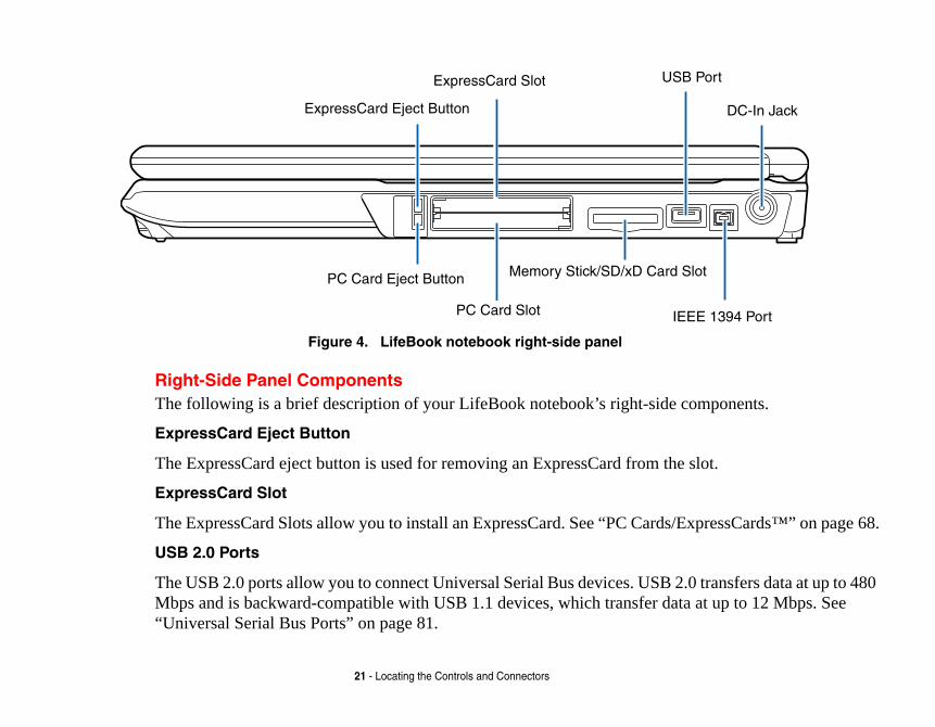
Figure 4. LifeBook notebook right-side panel
Right-Side Panel ComponentsThe following is a brief description of your LifeBook notebook’s right-side
ExpressCard Eject Button
The ExpressCard eject button is used for removing an ExpressCard from the
ExpressCard Slot
The ExpressCard Slots allow you to install an ExpressCard. See “PC Cards/E
USB 2.0 Ports
The USB 2.0 ports allow you to connect Universal Serial Bus devices. USB 2Mbps and is backward-compatible with USB 1.1 devices, which transfer da“Universal Serial Bus Ports” on page 81.
ExpressCard Eject Button
US
Memory Stick/SD/xD Card
IEPC Card Slot
ExpressCard Slot
PC Card Eject Button
eBook notebook and charge
1394 peripheral such as a
ecure Digital (SD) card, or from a variety of different
Cards/ExpressCards™” on
ard slot.
22 - Locating the Controls and Connectors
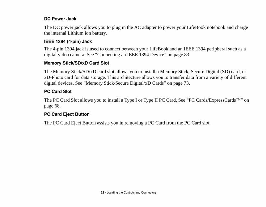
DC Power Jack
The DC power jack allows you to plug in the AC adapter to power your Lifthe internal Lithium ion battery.
IEEE 1394 (4-pin) Jack
The 4-pin 1394 jack is used to connect between your LifeBook and an IEEEdigital video camera. See “Connecting an IEEE 1394 Device” on page 83.
Memory Stick/SD/xD Card Slot
The Memory Stick/SD/xD card slot allows you to install a Memory Stick, SxD-Photo card for data storage. This architecture allows you to transfer datadigital devices. See “Memory Stick/Secure Digital/xD Cards” on page 73.
PC Card Slot
The PC Card Slot allows you to install a Type I or Type II PC Card. See “PCpage 68.
PC Card Eject Button
The PC Card Eject Button assists you in removing a PC Card from the PC C

mponents.
device.
2.0 transfers data at up to r data at up to 12Mbps. See
23 - Locating the Controls and Connectors
Figure 5. LifeBook notebook back panel
Back Panel ComponentsFollowing is a brief description of your LifeBook notebook’s back panel co
Anti-theft Lock Slot
The anti-theft lock slot allows you to attach an optional physical lock down
USB 2.0 Ports
The USB 2.0 ports allow you to connect Universal Serial Bus devices. USB480Mbps and is backward-compatible with USB 1.1 devices, which transfe“Universal Serial Bus Ports” on page 81.
Gigabit LAN (RJ-45) Jack
USB 2.0 Ports
Anti-Theft Lock Slot
Air Vents
External Video Jack
S-Video Out Port
USB Ports
Modem Jack

0Base-Tx/1000Base-T)
compatible TV or VCR.
ponents.
D projector. See “External
2.0 transfers data at up to 480 ta at up to 12 Mbps. See
ORMANCE, BE SURE TO KEEP THIS MAY REQUIRE PERIODIC M IS USED.
AN BE OBSTRUCTED, SUCH AS IN
24 - Locating the Controls and Connectors
Gigabit LAN (RJ-45) Jack
The internal LAN (RJ-45) jack is used for an internal Gigabit (10Base-T/10Ethernet LAN connection. See “Internal LAN (RJ-45) Jack” on page 80.
S-Video Out Port
The S-Video out port is used to transmit a high resolution video signal to a See “S-Video Out Port” on page 84.
Air Vents
The air vents allow air to circulate through the system to cool down the com
External Video Port
The external monitor port allows you to connect an external monitor or LCVideo Port” on page 82.
USB 2.0 Ports
The USB 2.0 ports allow you to connect Universal Serial Bus devices. USB Mbps and is backward-compatible with USB 1.1 devices, which transfer da“Universal Serial Bus Ports” on page 81.
TO PROTECT YOUR NOTEBOOK FROM DAMAGE AND TO OPTIMIZE PERF
ALL AIR ALL VENTS UNOBSTRUCTED, CLEAN, AND CLEAR OF DEBRIS.CLEANING, DEPENDING UPON THE ENVIRONMENT IN WHICH THE SYSTE
DO NOT OPERATE THE NOTEBOOK IN AREAS WHERE THE AIR VENTS CTIGHT ENCLOSURES OR ON SOFT SURFACES LIKE A BED OR CUSHION.

ternal multinational 56K
SYSTEMS. DO NOT CONNECT AMAGE TO THE INTERNAL URER’S DOCUMENTATION FOR D OUT BEFORE YOU CONNECT
0/V.92 STANDARD. ITS MAXIMUM UAL CONNECTION RATE S AT UPLOAD, IN ACCORDANCE
JITSU WEBSITE AT:
25 - Locating the Controls and Connectors
Modem (RJ-11) Telephone Jack The Modem (RJ-11) telephone jack is for attaching a telephone line to the inmodem. See “Modem (RJ-11) Telephone Jack” on page 79.
THE INTERNAL MODEM IS NOT INTENDED FOR USE WITH DIGITAL PBX THE INTERNAL MODEM TO A DIGITAL PBX AS IT MAY CAUSE SERIOUS DMODEM OR YOUR ENTIRE NOTEBOOK. CONSULT YOUR PBX MANUFACT
DETAILS. SOME HOTELS HAVE DIGITAL PBX SYSTEMS. BE SURE TO FIN
YOUR MODEM.
THE INTERNAL MULTINATIONAL MODEM IS DESIGNED TO THE ITU-T V.9SPEED OF 53000 BPS IS THE HIGHEST ALLOWED BY FCC, AND ITS ACT
DEPENDS ON THE LINE CONDITIONS. THE MAXIMUM SPEED IS 33600 BP
WITH FCC REGULATIONS.
FOR ADDITIONAL INFORMATION ABOUT THE MODEM, REFER TO THE FU
US.FUJITSU.COM/COMPUTERS.

nel components.
for the removal of the battery with a charged Lithium ion
namic RAM (DDR2 em memory capacity of your ule” on page 75. Under
Memory Upgrade Compartment
Lithium ion Battery Bay
26 - Locating the Controls and Connectors
Figure 6. LifeBook notebook bottom panel
Bottom ComponentsThe following is a brief description of your LifeBook notebook’s bottom pa
Lithium ion Battery Bay
The battery bay contains the internal Lithium ion battery. It can be unlatched when stored over a long period of time or for swapping a discharged batterybattery. See “Lithium ion Battery” on page 56.
Memory Upgrade Compartment
Your notebook comes with high speed Double Data Rate 2 Synchronous DySDRAM). The memory upgrade compartment allows you to expand the systnotebook, thus improving overall performance. See “Memory Upgrade Modnormal circumstances, it should not be necessary to open this compartment.

ts of your Fujitsu LifeBook ents is operating.
crLk
27 - Status Indicator Panel
Figure 7. Status Indicator Panel
Status Indicator PanelThe Status Indicators display symbols that correspond to specific componennotebook. The LEDs below each symbol tell you how each of those compon
Power Indicator
The Power indicator glows blue when your system is turned on.
NumLkCapsLk
S
Battery Level
Battery Charge/ Hard Drive/DC-In Optical Drive
Power

harging.ly charged, or AC adapter is
to charge battery (battery is
y pack, as follows:
econds after the battery is
attery level indicator will display
charged when the computer is at the rate of one second on/six
28 - Status Indicator Panel
Battery Charge/DC-In Indicator
• Orange, solid: AC adapter and battery are available and system is c• Green, solid: AC adapter and battery are available and system is ful
plugged in but battery is not installed.• Orange, blinking: AC adapter and battery are available and waiting
out of thermal range).• Off: AC adapter is not plugged in.
Battery Level Indicator
The Battery Level indicators display the charge level of the indicated batter
• Green, solid: Battery is between 51% and 100% charged.• Orange, solid: Battery is between 13% and 50% charged.• Red, solid: Battery is 12% or less charged.• Orange, blinking: Blinks during battery status measurement (Four s
installed).• Red, blinking: There is a problem with the battery.• Off: There is no battery installed or the battery has no charge.
• If the battery pack is installed while the power is turned off, the bthe charge level for five seconds after it blinks orange.
• If the AC adapter is not connected or the battery pack is not fullyswitched to standby mode, the indicator will blink. The LED blinksseconds off.

nal hard drive is being
ric keypad mode.
letters.
can be permanently
29 - Status Indicator Panel
Hard Drive/Optical Drive Access Indicator
The Hard Drive/Optical Drive Access indicator glows green when your interaccessed. Note that flickering is normal.
NumLk Indicator
The NumLk indicator states that the integral keyboard is set in ten-key nume
CapsLock Indicator
The CapsLock indicator states that your keyboard is set to type in all capital
ScrLk Indicator
The ScrLk indicator states that your scroll lock is active.
• Batteries subjected to shocks, vibration or extreme temperaturesdamaged.
• A shorted battery is damaged and must be replaced.

ys perform all the standard pecial function keys. This
Cursor Keys
30 - Keyboard
Keyboard
Figure 8. Keyboard
Using the KeyboardYour Fujitsu LifeBook notebook has an integral 86-key keyboard. The kefunctions of a 101-key keyboard, including the Windows keys and other ssection describes the following keys.
Fn Key Start Key
Function Keys
Numeric KeypadApplication Key
(surrounded by heavy line)
purposes, both as standard ggle between the standard y.the cursor or insertion point to ents. njunction with the [Fn] key to ning.
stem and function the same as device.
acter keys and numeric keypad the NumLk feature is done the 9, perform addition ( + ),
ts ( . ) using the keys designated the front edge of the key to
and an Application key. The nscreen Start menu button. The ys shortcut menus for the l information regarding the
to move the cursor up, down, oves the “focus” (selects the
31 - Keyboard
• Numeric keypad: Your notebook allows certain keys to serve dualcharacters and as numeric and mathematical keys. The ability to tocharacter and numerical keys is controlled through the [NumLk] ke
• Cursor keys: Your keyboard contains four arrow keys for moving the right, left, up, or down within windows, applications and docum
• Function keys: The keys labeled [F1] through [F12], are used in coproduce special actions that vary depending on what program is run
• Windows keys: These keys work with your Windows operating sythe onscreen Start menu button, or the right button on your pointing
Numeric Keypad
Certain keys on the keyboard perform dual functions as both standard charkeys. NumLk can be activated by pressing the [NumLk] keys. Turning offsame way. Once this feature is activated you can enter numerals 0 throughsubtraction ( - ), multiplication ( * ), or division ( / ), and enter decimal poinas ten-key function keys. The keys in the numeric keypad are marked on indicate their secondary functions.
Windows Keys
Your LifeBook notebook has two Windows keys, consisting of a Start keyStart key displays the Start menu. This button functions the same as your oApplication key functions the same as your right mouse button and displaselected item. (Please refer to your Windows documentation for additionaWindows keys.)
Cursor Keys
The cursor keys are the four arrow keys on the keyboard which allow youleft and right in applications. In programs such as Windows Explorer, it mnext item up, down, left, or right).

ns assigned to these keys differ nd out how these keys are used.
lways used in conjunction with
ute on and off.e brightness of your display. the brightness of the display. the volume of your LifeBook
the volume of your LifeBook
our selection of where to send ou will step to the next choice. itor only, and both built-in
32 - Keyboard
Function Keys
Your LifeBook notebook has 12 function keys, F1 through F12. The functiofor each application. You should refer to your software documentation to fi
• The [Fn] key provides extended functions for the notebook and is aanother key.
• [Fn+F3]: Pressing [F3] while holding [Fn] will toggle the Audio M• [Fn+F6]: Pressing [F6] repeatedly while holding [Fn] will lower th• [Fn+F7]: Pressing [F7] repeatedly while holding [Fn] will increase• [Fn+F8]: Pressing [F8] repeatedly while holding [Fn] will decrease
notebook.• [Fn+F9]: Pressing [F9] repeatedly while holding [Fn] will increase
notebook.• [Fn+F10]: Pressing [F10] while holding [Fn] allows you to change y
your display video. Each time you press the combination of keys yThe choices, in order, are: built-in display panel only, external mondisplay panel and external monitor.

ook. It is used to control the d is composed of a cursor
depending upon your system
r around the display. It only function the same as mouse pplication that is being used. ckly navigate through pages. ed by a fingerprint sensor, Device” on page 164.)
33 - Touchpad Pointing Device
Touchpad Pointing Device
Figure 9. Touchpad pointing device
The Touchpad pointing device comes built into your Fujitsu LifeBook notebmovement of the pointer to select items on your display panel. The Touchpacontrol, a left button, a right button, and a scroll button (or fingerprint sensor,configuration).
The cursor control works the same way a mouse does, and moves the cursorequires light pressure with the tip of your finger. The left and right buttonsbuttons. The actual functionality of the buttons may vary depending on the aBetween the left and right buttons is the scroll button which allows you to quiDepending upon your system configuration, the scroll button may be replacwhich is used to secure your system. (See “Appendix B: Fingerprint Sensor
Cursor Control or
Left Button
Right Button
Scroll button or optional Fingerprint Sensor
OUR LIFEBOOK NOTEBOOK AND T THE SYSTEM WITH AN ENABLED DEPENDING ON THE ge 48.
licking with button
icking with Touchpad
34 - Touchpad Pointing Device
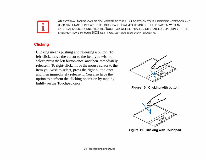
Clicking
AN EXTERNAL MOUSE CAN BE CONNECTED TO THE USB PORTS ON YUSED SIMULTANEOUSLY WITH THE TOUCHPAD. HOWEVER, IF YOU BOO
EXTERNAL MOUSE CONNECTED THE TOUCHPAD WILL BE DISABLED OR
SPECIFICATIONS IN YOUR BIOS SETTINGS. See “BIOS Setup Utility” on pa
Clicking means pushing and releasing a button. To left-click, move the cursor to the item you wish to select, press the left button once, and then immediately release it. To right-click, move the mouse cursor to the item you wish to select, press the right button once, and then immediately release it. You also have the option to perform the clicking operation by tapping lightly on the Touchpad once.
Figure 10. C
Figure 11. Cl

uble-clicking with button
ble-clicking with Touchpad
35 - Touchpad Pointing Device
Double-Clicking
Double-clicking means pushing and releasing the left button twice in rapid succession. This procedure does not function with the right button. To double-click, move the cursor to the item you wish to select, press the left button twice, and immediately release it. You can also perform the double-click operation by tapping lightly on the Touchpad twice.
Figure 12. Do
Figure 13. Dou

selections made from within
. Dragging with button
Dragging with Touchpad
36 - Touchpad Pointing Device
Dragging
Touchpad Control AdjustmentThe Windows Control Panel allows you to customize your Touchpad withthe Mouse Properties dialog box.
Dragging means pressing and holding the left button, while moving the cursor. To drag, move the cursor to the item you wish to move. Press and hold the left button while moving the item to its new location and then release it. Dragging can also be done using the Touchpad. First, tap the Touchpad twice over the item you wish to move making sure to leave your finger on the pad after the final tap. Next, move the object to its new location by moving your finger across the Touchpad, and then release your finger.
Figure 14
Figure 15.
37 - Volume Control
Volume ControlYour Fujitsu LifeBook notebook has multiple volume controls which interact with each other.
Controlling the VolumeThe volume can be controlled in several different ways:
• Volume can be changed using the [Vol -] and [Vol +] buttons above the keyboard.• Volume can be changed or muted from within the Volume Control in the system tray.• Volume can be controlled with the F8 and F9 functions keys. Pressing [F8] repeatedly while holding
[Fn] will decrease the volume of your notebook. Pressing [F9] repeatedly while holding [Fn] will increase the volume of your notebook.
• Volume can be muted by pressing the [F3] key while holding down the [Fn] key. To restore audio, repeat the [Fn+F3] procedure.
• Volume can be controlled by many volume controls that are set within individual applications.• Certain external audio devices you might connect to your system may have hardware volume
controls.Each source discussed above puts an upper limit on the volume level that must then be followed by the other sources.
We recommend that you experiment with the various volume controls to discover the optimal sound level.
ANY SOFTWARE THAT CONTAINS AUDIO FILES WILL ALSO CONTAIN A VOLUME CONTROL OF ITS OWN. IF YOU INSTALL AN EXTERNAL AUDIO DEVICE THAT HAS AN INDEPENDENT VOLUME CONTROL, THE HARDWARE VOLUME CONTROL AND THE SOFTWARE VOLUME CONTROL WILL INTERACT WITH EACH OTHER. IT SHOULD BE NOTED THAT IF YOU SET YOUR SOFTWARE VOLUME TO OFF, YOU WILL OVERRIDE THE EXTERNAL VOLUME CONTROL SETTING.

ned applications with the pport button that allows you application.
button when your system is otebook is pre-installed with on Panel. These utilities are . They include two
38 - LifeBook Application Panel/Support Button
Figure 16. LifeBook Application Panel
LifeBook Application Panel/Support ButtonThe Application Panel consists of buttons that allow you to launch user-defitouch of a button when your system is on. Also included in the panel is a Suto either launch the Fujitsu Support Center utility or to launch a user-defined
Launching Applications with the LifeBook Application PanelThe application panel enables you to launch applications with the touch of aon. Pressing any of the buttons will launch a user-defined application. Your nsoftware utilities that let you operate and configure your LifeBook Applicatifound in the Start menu, under Settings > Control Panel > Application PanelApplication Panel Setup tabs, E-mail Setup, and Internet Setup.
Support A B VolWebSearchHome
My

activated. As an application iety of options. To set up the utility that quickly and easily
Setup:
. There are tabs that correspond e your notebook, these buttons this document.
e tab for the button you would art Menu, scroll down the list nd then click OK. The button
nternet browser (Internet it to launch another program
to launch with this button.
RDER AS THE BUTTONS ON YOUR E CAREFULLY.
39 - LifeBook Application Panel/Support Button
Configuring your LifeBook Application Panel
When you start Windows, the LifeBook Application Panel is automaticallylauncher, the LifeBook Application Panel is very flexible, giving you a varPanel to best suit your needs, we have provided the Application Panel Setuphelps you make the most of this valuable feature.
To configure your LifeBook Application Panel with Application Panel
1 Click on [Start].
2 Click on Programs, then click on LifeBook Application Panel.
3 Click on Application Panel Setup. The Application Panel Setup utility will appearto the application buttons on the LifeBook Application Panel. When you receivare pre-configured to launch specific programs, as referenced in Chapter 7 of
To change an application associated with the Application buttons, click on thlike to reconfigure – for example, Application A. Click on Browse from Stof applications, click on the application you wish to launch with this button, awill now launch the new application.
The Internet tab is different. It comes set to launch your Windows default IExplorer), unless you have changed this in Windows. In order to reconfigurefollow these easy steps:1 Click on Other from the Internet browser box.
2 Click on Browse from Start Menu.
3 Scroll down the list of applications, and then click on the application you wish
THE TABS IN APPLICATION PANEL SETUP MAY NOT BE IN THE SAME OLIFEBOOK NOTEBOOK, PLEASE SELECT THE TAB YOU WISH TO CHANG

to launching your Windows t Browser” from the Internet ”. If you wish to go back to t as described above.
settings will take effect. You
en it is on.
art Boot Menu which allows Utility to perform a number
rt Center utility which offers
download the system User’s
en open the boot menu, from pressing the button when the m Information.
BUTTONS TO BE AN INTERNET PPLICATION YOU WISH, NOT JUST
40 - LifeBook Application Panel/Support Button
4 Click OK. The button will now launch the new application. If you want to returndefault Internet browser with this button, you need only click on “Default Internebrowser box. Be aware that you will erase the settings for the “other applicationlaunching the “other application” from this button, you will need to reconfigure i
When you have finished with Application Panel Setup click OK, and the newcan reconfigure your LifeBook Application Panel as often as you like.
Opening the Fujitsu Support Center with the Support ButtonThe Support button performs different actions when the system is off or wh
When the system is off, pressing the Support button will open the Fujitsu Styou to select either Diagnostic Program to test your system or Recovery andof other functions, including recovery of your system.
When the system is on, pressing the Support button invokes the Fujitsu Suppothree tabs: Manual, Diagnostic Program, and Support.
Manual tab
The Manual tab lets you automatically go to the Fujitsu Support website to Guide. (You must be connected to the Internet in order to use this function).
Diagnostic Program tab
The Diagnostic Program tab allows you to automatically reboot the system, thwhich you can choose Diagnostic Program or Recovery and Utility (same as system is shut down). From the Diagnostic tab you can also view your Syste
IF YOUR SYSTEM HAS DEDICATED ONE OF THE APPLICATION LAUNCHER
LAUNCHER, THE BUTTON CAN STILL BE CONFIGURED TO LAUNCH ANY AAN INTERNET BROWSER.

st be connected to the Internet
re your LifeBook Application Panel > Application Panel (or el Setup tab.
activated. As an application our needs, we have provided f this valuable feature.
Setup:
r. There is a tab that corresponds figured to launch the Fujitsu tton” on page 40. To reconfigure
to launch with this button.
tton, click on Fujitsu Support er application”. If you wish to go onfigure it as described above.
ettings will take effect. You can
41 - LifeBook Application Panel/Support Button
Support tab
The Support tab lets you automatically go to the Support Website. (You muin order to access the Support website).
Launching Applications with the Support ButtonYour notebook is pre-installed with utilities that let you operate and configuPanel. These utilities are found in the Start menu, under Settings > Control “Buttons” in some configurations). The utility includes an Application Pan
Configuring your LifeBook Application Panel
When you start Windows, the LifeBook Application Panel is automaticallylauncher, the application panel is very flexible. To set up the panel to suit ythe Application Panel Setup utility that quickly helps you make the most o
To configure your LifeBook Application Panel with Application Panel
1 Click on [Start] > Programs > LifeBook Application Panel.
2 Click on Application Panel Setup. The Application Panel Setup utility will appeato the Support button. When you receive your notebook, this button is pre-conSupport Center. See “Opening the Fujitsu Support Center with the Support Buit to launch another program proceed to the following steps.
1 Click on [Application Registration].
2 Click the “Select from Start Menu” box.
3 Scroll down the list of applications, and then click on the application you wish
4 Click [Next], [Finish], [OK]. The button will now launch the new application.
5 If you want to return to launching the Fujitsu Support Center utility with this buCenter from the dropdown list. Note that this will erase the settings for the “othback to launching the “other application” from this button, you will need to rec
6 When you have finished with Application Panel Setup click OK, and the new sreconfigure your LifeBook Application Panel as often as you like.

Book
Poweary Lithium ion battery, an AC
DC Power Jack
42
Chapter 2
Getting Started with Your Life
Figure 17. Connecting the AC Adapter
r SourcesYour Fujitsu LifeBook notebook has three possible power sources: a primadapter or an optional Auto/Airline adapter.
AC Adapter

ating your notebook and
e ignition key in the On or Access
ttery Power
IALLY, YOU WILL NEED TO CONNECT YOUR NOTEBOOK.
43 - Power Sources
Connecting the Power AdaptersThe AC adapter or optional Auto/Airline adapter provides power for opercharging the batteries.
Connecting the AC Adapter 1 Plug the DC output cable into the DC power jack of your LifeBook notebook.
2 Plug the AC adapter into an AC electrical outlet.
Connecting the Optional Auto/Airline Adapter 1 Plug the DC output cable into the DC power jack on your notebook.
2 Plug the Auto/Airline adapter into the cigarette lighter of an automobile with thOR
3 Plug the Auto/Airline adapter into the DC power jack on an airplane seat.
Switching from AC Adapter Power or the Auto/Airline Adapter to Ba
1 Be sure that you have at least one charged battery installed.
2 Remove the AC adapter or the Auto/Airline adapter.
THE LITHIUM ION BATTERY IS NOT CHARGED UPON PURCHASE. INIT
EITHER THE AC ADAPTER OR THE AUTO/AIRLINE ADAPTER TO USE

r easier viewing in bright ix technology.
, allowing you to raise the display.
a comfortable viewing angle.
44 - Display Panel
Figure 18. Opening the Display Panel
Display PanelYour Fujitsu LifeBook notebook contains a display panel that is backlit foenvironments and maintains top resolution through the use of active-matr
Opening the Display Panel1 Press the Display Panel latch button in. This releases the locking mechanism
2 Lift the display backwards, being careful not to touch the screen, until it is at
Display Panel Latch Button

he brightness level of the e brightness. Two of them
one survives restarts and
arily.
.y.
rebooted or resumed,
ne.
n plugged in.
of your LifeBook notebook.
revent your display panel from
EL BY DEFAULT. WHEN USING BAT-BY DEFAULT.
E AND THE FASTER YOUR BATTER-TNESS IS SET AS LOW AS POSSIBLE.
45 - Display Panel
Adjusting Display Panel BrightnessOnce you have turned on your LifeBook notebook, you may want to adjust tscreen to a more comfortable viewing level. There are three ways to adjust thare temporary (by using the keyboard or the power management utility) and resumes (using the Power Options control panel).
Using the KeyboardAdjusting the brightness using the keyboard changes the setting only tempor
• [Fn+F6]: Pressing repeatedly will lower the brightness of your display• [Fn+F7]: Pressing repeatedly will increase the brightness of the displa
Using the Power OptionsTo adjust the brightness so that the setting changes remain after the system isperform the following:1 Click the Start icon, then select Control Panel.
2 Select Power Options, then click on “Adjust to Display Brightness” in the left pa
3 Set the desired brightness for the display when it is running on battery and whe
4 Click [Save changes]..
Closing the Display Panel1 Holding the edge of your display panel, pull it forward until it is flush with the body
2 Push down until you hear a click. This will engage the locking mechanism and popening unexpectedly.
■ WHEN USING AC POWER YOUR BRIGHTNESS SETTING IS SET TO ITS HIGHEST LEV
TERY POWER YOUR BRIGHTNESS SETTING IS SET TO APPROXIMATELY MID-LEVEL
■ THE HIGHER THE BRIGHTNESS, THE MORE POWER THE NOTEBOOK WILL CONSUM
IES WILL DISCHARGE. FOR MAXIMUM BATTERY LIFE, MAKE SURE THAT THE BRIGH

ok from its off state. Once tery, you can power on your
nd/Resume button, located leave your notebook in Off” on page 55) .
OST) to check the internal Book notebook will emit an
essages” on page 98.) Depending rating system or by entering
rating system.
A POWER SOURCE. THIS MEANS TO/AIRLINE ADAPTER IS
ON OR SUBJECT IT TO SHOCKS
46 - Starting Your LifeBook Notebook
Starting Your LifeBook Notebook
Power On
Power/Suspend/Resume Button
The Power/Suspend/Resume button is used to turn on your LifeBook noteboyou have connected your AC adapter or charged the internal Lithium ion batLifeBook notebook.
To turn on your LifeBook notebook from its off state, press the Power/Suspeabove the keyboard to the right. When you are done working you can either Suspend mode (“Sleep Mode” on page 52), or you can turn it off (“Powering
When you power on your LifeBook, it will perform a Power On Self Test (Pparts and configuration for correct functionality. If a fault is found, your Lifeaudio warning and/or an error message will be displayed. (See “Power On Self Test M
on the nature of the problem, you may be able to continue by starting the opethe BIOS setup utility and revising the settings.
After satisfactory completion of the POST, your notebook will load your ope
WHEN YOU TURN ON YOUR LIFEBOOK NOTEBOOK, BE SURE YOU HAVE THAT A BATTERY IS INSTALLED AND CHARGED, OR THAT THE AC OR AU
CONNECTED AND HAS POWER.
DO NOT CARRY YOUR LIFEBOOK NOTEBOOK AROUND WITH THE POWER
OR VIBRATION, AS YOU RISK DAMAGING YOUR NOTEBOOK.

e and involves your notebook’s memory is empty, and it needs IOS program. Each time you displays a Fujitsu logo until ing a standard boot sequence leted without a failure and ating system’s opening screen.
x.a new application.
your hard disk drive(s). This ty below for information about
ON SELF TEST (POST) OR IT WILL UR LIFEBOOK NOTEBOOK ON THE
ER AND MASTER HARD DISK ESET IT. YOU MAY LOSE DATA AND
47 - Starting Your LifeBook Notebook
Boot SequenceThe procedure for starting-up your notebook is termed the Bootup sequencBIOS. When your LifeBook notebook is first turned on, the main system to find instructions to start up your notebook. This information is in the Bpower up or restart your notebook, it goes through a boot sequence whichyour operating system is found. During booting, your notebook is performincluding a Power On Self Test (POST). When the boot sequence is compwithout a request for the BIOS Setup Utility, the system displays the oper
The boot sequence is executed when:
• You turn on the power to your LifeBook notebook.• You restart your notebook from the Windows Shut Down dialog bo• The software initiates a system restart. Example: When you install
Hard Disk Drive PasswordsTo provide additional security for your data, you can assign passwords tofeature is managed in the system BIOS Setup Utility. See BIOS Setup Utiliaccessing the utility.
NEVER TURN OFF YOUR LIFEBOOK NOTEBOOK DURING THE POWER
CAUSE AN ERROR MESSAGE TO BE DISPLAYED WHEN YOU TURN YO
NEXT TIME. See “Power On Self Test Messages” on page 98.
REMEMBER YOUR PASSWORDS. IF YOU SET AND FORGET YOUR US
PASSWORDS, FUJITSU COMPUTER SYSTEMS WILL NOT BE ABLE TO RHAVE TO REPLACE YOUR SYSTEM BOARD OR HARD DISK DRIVE.

or your LifeBook notebook. re is no need to set or change
d boot devices.
enu, as detailed below):
s on the screen. This will open
etup menus to review or alter
n the left mouse or touchpad shortcuts to the following
48 - Starting Your LifeBook Notebook
BIOS Setup UtilityThe BIOS Setup Utility is a program that sets up the operating environment fYour BIOS is set at the factory for normal operating conditions, therefore thethe BIOS’ environment to operate your notebook.
The BIOS Setup Utility configures:
• Device control feature parameters, such as changing I/O addresses an• System Data Security feature parameters, such as passwords.
Entering the BIOS Setup Utility
To enter the BIOS Setup Utility do the following (or use the TrustedCore M1 Turn on or restart your LifeBook notebook.
2 To enter the BIOS Setup Utility, press the [F2] key once the Fujitsu logo appearthe main menu of the BIOS Setup Utility with the current settings displayed.
3 Press the [RIGHT ARROW] or [LEFT ARROW] key to scroll through the other sthe current settings.
Using the TrustedCore Menu
When the Fujitsu logo appears on the screen. press the [Enter] key or click obutton; the TrustedCore Menu will appear. The TrustedCore Menu providesmenus and information screens:
• BIOS Setup• Diagnostic Screen• Boot Menu• Patent Information• System Information• Continue Booting

escribed.
u logo appears on the screen.
e and support website at nder Online Support. Select lect the BIOS Guide.
put a DVD/CD in your drive
ogo on the screen. If you do elcome will begin.
a operating system, it should
USED FOR LONG PERIODS OF M OR CONTINUOUS USE WHILE
EEN WILL BE BLANK FOR A “SET UP WINDOWS” DIALOG BOX
POWER SUPPLY, PRESS ANY RD, OR REMOTE CONTROL.
ECT LANGUAGE IS SELECTED, YOU
49 - Starting Your LifeBook Notebook
Clicking on any of the fields will invoke the screen, information, or action d
The Boot Menu can also be invoked by pressing the [F12] key when the Fujits
BIOS Guide
A guide to your notebook’s BIOS is available online. Please visit our servichttp://www.computers.us.fujitsu.com/support, then select User’s Guides uyour Product, Series, and Model, then click [Go]. Under the Manuals tab, se
Booting the SystemWe strongly recommend that you not attach any external devices and do not until you have gone through the initial power on sequence.
When you turn on your notebook for the first time, it will display a Fujitsu lnothing the system will load the operating system, and then the Windows W
Starting Windows Vista the first time
In order to ensure that you receive the most benefits from the Windows Vistbe registered the first time you use it.
THE BOTTOM OF THIS NOTEBOOK COMPUTER CAN BECOME HOT WHEN
TIME. WHEN USING THE NOTEBOOK, TAKE CAUTION TO LIMIT LONG TER
RESTING IT ON EXPOSED SKIN, SUCH AS THE LAP.
• THE FIRST TIME YOU INITIALIZE YOUR WINDOWS VISTA SYSTEM, THE SCR
APPROXIMATELY TWO MINUTES. THIS IS NORMAL. AFTER INITIALIZATION, WILL APPEAR.
• IMPORTANT: DURING THE SETUP PROCEDURE, DO NOT DISCONNECT THE
BUTTONS, OR USE ANY PERIPHERAL DEVICES SUCH AS A MOUSE, KEYBOA
• USE CARE WHEN PROMPTED TO SELECT YOUR LANGUAGE; IF THE INCORR
WILL NEED TO PERFORM A COMPLETE SYSTEM RECOVERY.

nts (EULAs).
given a chance to select an icon
ktop background.
default choice is "Use s only" and "Ask me later". Select
your selection from Home, Work
is extended. Following are several
u initialize your Windows Vista al. During this period, do not es such as mouse, keyboard, or
enter will appear. If the Register where “xx” is the number of topics
register your copy of Windows.
E ASKED TO REVIEW THE LICENSE T DOWN YOUR LIFEBOOK NOTEBOOK.
ENSE AGREEMENTS. IF YOU STOP THE INDOWS WELCOME PROCESS, EVEN IF
50 - Starting Your LifeBook Notebook
1 First of all, you will need to read and accept the End User License Agreeme
2 You will be prompted to enter your User Name and Password and you will befor your account.
3 The next screen asks for a Computer Name and allows you to choose a des
4 You will next see a "Help protect Windows automatically" screen in which therecommended settings”. The other two choices are "Install important updatefrom the three choices.
5 On the next screen set your time and date settings.
6 You will next see the "Select your computer's current location" screen. Make(Default), and Public location.
7 The "Thank you" screen follows and an offer for free Norton Internet Security screens while Windows checks the system performance.
8 Windows will then boot up for the first time. As noted above, the first time yosystem, the screen will be blank for approximately two minutes. This is normdisconnect the power supply, press any buttons, or use any peripheral devicremote control.
Registering Windows Vista with Microsoft
1 After Windows has booted up for the first time, the Control Panel Welcome CWindows Online icon is not seen in the window, click on “Show all xx items” (in the Welcome Center).
2 Click on Register Windows Online and follow the instructions that appear to
• IF YOU REJECT THE TERMS OF THE LICENSE AGREEMENTS YOU WILL BAGREEMENTS FOR INFORMATION ON RETURNING WINDOWS OR TO SHU
• YOU CANNOT USE YOUR NOTEBOOK UNTIL YOU HAVE ACCEPTED THE LIC
PROCESS YOUR NOTEBOOK WILL RETURN TO THE BEGINNING OF THE WYOU SHUT YOUR NOTEBOOK DOWN AND START IT UP AGAIN.

computers
r online.
e PC” window. This window If you click [Execute], Click count Control” window, you . If you cancel the operation,
tility. With FDU, you can updates for your system. For ng Driver Updates” on
AN SWITCH IS TURNED ON.
ME!, OTHER THIRD-PARTY S.
51 - Starting Your LifeBook Notebook
Registering Your LifeBook notebook with FujitsuYou can register your LifeBook by going to our website at: us.fujitsu.com/
You will need to be set up with an Internet Service Provider (ISP) to registe
Installing Click Me!
The first time you boot up your system, you will see a “Primary Settings for thexplains the installations which will be performed by the Click Me! utility. Me! will begin installing. If after clicking the button you receive a “User Acwill be asked for your permission to continue. Click [Continue] to continuethe Click Me! icon will appear on your desktop for later installation.
Fujitsu Driver Update Utility
Your system has a convenient tool called the Fujitsu Driver Update (FDU) uchoose to automatically or manually go to the Fujitsu site to check for new more information about the FDU utility, refer to “Automatically Downloadipage 83.
BEFORE INSTALLING THE CLICKME! UTILITY, BE SURE THE WIRELESS L
IN ADDITION TO THE UTILITIES AND APPLICATIONS INSTALLED BY CLICK
APPLICATIONS MAY NEED TO BE INSTALLED FROM THE INCLUDED DISC

g battery power. Some of internal modem. However, s, such as those for the ntrolled from settings made m settings made in BIOS
e things that you can do to eate an appropriate power an operation, and you can puters, there is a trade-off
d to manually put the notebook is active, but not
ar two short beeps and the
turns your notebook to the Power indicator. If the indicator is visible and wer is off or your notebook
eriods of inactivity by drive, and all other internal rting.
52 - Power Management
Power ManagementYour Fujitsu LifeBook notebook has many options and features for conservinthese features are automatic and need no user intervention, such as those for theothers depend on the parameters you set to best suit your operating conditiondisplay brightness. Internal power management for your notebook may be coin your operating system, pre-bundled power management application, or frosetup utility.
Besides the options available for conserving battery power, there are also somprevent your battery from running down as quickly. For example, you can crsaving profile, put your notebook into Sleep mode when it is not performing limit the use of high power devices. As with all mobile, battery powered combetween performance and power savings.
Power/Suspend/Resume ButtonWhen your notebook is active, the Power/Suspend/Resume button can be usenotebook into Sleep mode. Push the Power/Suspend/Resume button when theactively accessing anything, and immediately release the button. You will hesystem will enter Sleep mode.
If your notebook is suspended, pushing the Power/Suspend/Resume button reactive operation. You can tell whether the system is Suspended by looking atindicator is visible and not flashing, your notebook is fully operational. If theflashing, your notebook is in Sleep mode. If the indicator is not visible, the pois in Hibernation mode. (See Hibernation Feature)
Sleep ModeSleep mode in Windows saves the contents of your system memory during pmaintaining power to critical parts. This mode turns off the CPU, display, hardcomponents except those necessary to maintain system memory and for resta

rned on.
e working, open application . When you resume operation You must use the adequate power source
ATTERY CONTINUES TO DISCHARGE N FULLY OPERATIONAL.
ING USED TO PUT THE NOTEBOOK INTO NCTION CAN’T BE DISABLED.
D WITH CERTAIN PC CARDS. CHECK RDS OR EXTERNAL DEVICES ARE IN STATE PRIOR TO SUSPENSION,
THE SYSTEM RESTARTS.
ER THE SLEEP OR HIBERNATION ARE LEFT OPEN AND MEMORY IS KEPT
TERNAL HARD DRIVE DURING HIBERNA-
WER IS NOT REQUIRED TO MAINTAIN UR NOTEBOOK IN A SUSPENDED STATE ON MODE IS THAT IT LENGTHENS THE ES.
53 - Power Management
Your notebook can be put in Sleep mode by:
• Pressing the Power/Suspend/Resume button when your system is tu• Selecting Sleep from the Windows Shut Down menu.• Timing out from lack of activity.• Allowing the battery to reach the Dead Battery Warning condition.
Your notebook’s system memory typically stores the file on which you arinformation, and any other data required to support operations in progressfrom Sleep mode, your notebook will return to the point where it left off. Power/Suspend/Resume button to resume operation, and there must be anavailable, or your notebook will not resume.
■ IF RUNNING YOUR NOTEBOOK ON BATTERY POWER, BE AWARE THAT THE BWHILE YOUR NOTEBOOK IS IN SLEEP MODE, THOUGH NOT AS FAST AS WHE
■ DISABLING THE POWER/SUSPEND/RESUME BUTTON PREVENTS IT FROM BE
SLEEP OR HIBERNATION (SAVE-TO-DISK) MODE. THE BUTTON RESUME FU
■ THE SLEEP OR HIBERNATION (SAVE-TO-DISK) MODE SHOULD NOT BE USE
YOUR PC CARD DOCUMENTATION FOR MORE INFORMATION. WHEN PC CA
USE, HIBERNATION (SAVE-TO-DISK) MODE CANNOT RETURN TO THE EXACT
BECAUSE ALL OF THE PERIPHERAL DEVICES WILL BE RE-INITIALIZED WHEN ■ IF YOUR NOTEBOOK IS ACTIVELY ACCESSING INFORMATION WHEN YOU ENT
(SAVE-TO-DISK) MODE, CHANGES TO OPEN FILES ARE NOT LOST. THE FILES
ACTIVE DURING SLEEP MODE OR THE MEMORY IS TRANSFERRED TO THE INTION MODE.
THE MAIN ADVANTAGE OF USING HIBERNATION (SAVE-TO-DISK) IS THAT PO
YOUR DATA. THIS IS PARTICULARLY IMPORTANT IF YOU WILL BE LEAVING YO
FOR A PROLONGED PERIOD OF TIME. THE DRAWBACK OF USING HIBERNATI
POWER DOWN AND POWER UP SEQUENCES AND RESETS PERIPHERAL DEVIC

ory to the hard drive as a part
feature follow these steps:
does”, then make your selections
to configure some of the power the timeout values for turning attery power or one of the
lowing procedure.
WS OR TURNING ON YOUR F MAY CAUSE AN ERROR WHEN
54 - Power Management
Hibernation (Save-to-Disk) FeatureThe Hibernation feature saves the contents of your notebook’s system memof the Suspend/Resume mode. You can enable or disable this feature.
Enable or Disable the Hibernation Feature
The default settings are not enabled. To enable or disable the Hibernation1 From the Start menu, select Control Panel.
2 Select “Choose what the power button does” or “Choose what closing the lid(Do Nothing, Sleep, Hibernate, or Shut Down).
Windows Power Management The Power Options icon located in the Windows Control Panel allows you management settings. For example, you can use the Power Options to setoff the display and hard disks whether you are running the notebook on badapters.
Restarting the SystemIf your system is on and you need to restart it, be sure that you use the fol1 Click the Start button, and then move the mouse over the right arrow.
2 Select the desired action from the list.
TURNING OFF YOUR LIFEBOOK NOTEBOOK WITHOUT EXITING WINDO
NOTEBOOK WITHIN 10 SECONDS OF THE NOTEBOOK BEING SHUT OF
YOU START THE NEXT TIME.

indicator is off. If you turn off t your notebook shuts down
ook to complete its operations uence is:
x.
Maintenance Section.
G OFF THE POWER. IF FILES ARE OPEN AVE NOT BEEN SAVED, AND MAY CAUSE
PACKAGING IT. AFTER SHUTTING DOWN FF CONDITION (I.E., NO LIGHTS ARE
OFF OR HIBERNATE MODE WHEN YOU SWORD SECURITY SETTINGS OR SOME
AMAGE THE NOTEBOOK DUE TO SHOCK TED.
55 - Power Management
Powering OffBefore turning off the power, check that the hard drive/optical drive accessthe power while accessing a disk there is a risk of data loss. To ensure thawithout error, use the Windows shut down procedure.
Using the correct procedure to shut down from Windows allows your noteband turn off power in the proper sequence to avoid errors. The proper seq1 Click the Start button, and then click Shut Down.
2 Select the Shut Down option from within the Windows Shut Down dialog bo
3 Click OK to shut down your notebook.
If you are going to store your notebook for a month or more see Care and
• BE SURE TO CLOSE ALL FILES, EXIT ALL APPLICATIONS PRIOR TO TURNIN
WHEN YOU TURN THE POWER OFF, YOU WILL LOSE ANY CHANGES THAT HDISK ERRORS.
• ALWAYS POWER OFF THE COMPUTER BEFORE TRANSPORTING AND/OR THE SYSTEM, WAIT UNTIL THE STATUS LED PANEL INDICATES POWER OILLUMINATED).
• IT IS POSSIBLE THAT THE UNIT MAY NOT AUTOMATICALLY GO TO POWER
CLOSE THE LID. THIS SITUATION MAY OCCUR DUE TO PRE-OS BOOT PAS
OTHER APPLICATION RUNNING ON THE COMPUTER.
• ATTEMPTING TO TRANSPORT THE COMPUTER WHILE POWER IS ON MAY DOR OVERHEATING SINCE THE AIR VENTS MAY BE BLOCKED OR RESTRIC

Lithiuerating your notebook when , but should not be exposed
r the following conditions:
. Extreme temperatures not n. The Charging icon on the is outside its operating
D Writer, external CD-ROM pter will conserve your
YOUR AC ADAPTER, OPTIONAL LF. IT MAY ALSO PREVENT INTO THE BAD BATTERY.
56
Chapter 3
User-Installable Features
m ion BatteryYour LifeBook notebook has a Lithium ion battery that provides power for opno external power source is available. The battery is durable and long lastingto extreme temperatures, high voltages, chemicals or other hazards.
The Lithium ion battery operating time may become shorter if it is used unde
• When used at temperatures that exceed a low of 5°C or a high of 35°Conly reduce charging efficiency, but can also cause battery deterioratioStatus Indicator panel will flash when you try to charge a battery that temperature range. See “Status Indicator Panel” on page 27.
• When using a high current device such as a modem, Multi-Format DVdrive, DVD/CD-RW combo drive, or the hard drive, using the AC adabattery life.
DO NOT LEAVE A FAULTY BATTERY IN YOUR NOTEBOOK. IT MAY DAMAGE
AUTO/AIRLINE ADAPTER, ANOTHER BATTERY OR YOUR NOTEBOOK ITSE
OPERATION OF YOUR NOTEBOOK BY DRAINING ALL AVAILABLE CURRENT

ck the Battery Level indicator level changes.to/Airline adapter. To recharge our LifeBook notebook and
t need to discharge the battery er if your notebook is in use ly, put your notebook into Power Management on page
APPLICATIONS, FEATURES, POWER MER PREFERENCES. CD-ROM , OR HARD DRIVE USAGE MAY ALSO RGING CAPACITY IS REDUCED AS YOU SHOULD REPLACE IT WITH A
SPOSE OF BATTERIES BY PUTTING ND DISPOSE OF BATTERIES R DETAILS REGARDING RECYCLING RMATION ELSEWHERE, CONTACT 38-5487)
RCENTAGE CHARGE IS DISPLAYED NEL.
57 - Lithium ion Battery
Recharging the BatteriesIf you want to know the condition of the primary Lithium ion battery, chelocated on the Status Indicator panel. The indicator changes as the batteryThe Lithium ion battery is recharged internally using the AC adapter or Authe battery make sure the battery that needs to be charged is installed in yconnect the AC or Auto/Airline adapter.
There is no memory effect on the Lithium ion battery therefore you do nocompletely before recharging. The charge times will be significantly longwhile the battery is charging. If you want to charge the battery more quickStandby mode, or turn it off while the adapter is charging the battery. (See52 for more information on Standby mode and shutdown procedure)
• ACTUAL BATTERY LIFE WILL VARY BASED ON SCREEN BRIGHTNESS,MANAGEMENT SETTINGS, BATTERY CONDITION AND OTHER CUSTO
DRIVE, MULTI-FORMAT DVD WRITER, DVD/CD-RW DRIVE COMBO
HAVE A SIGNIFICANT IMPACT ON BATTERY LIFE. THE BATTERY CHA
THE BATTERY AGES. IF YOUR BATTERY IS RUNNING LOW QUICKLY,NEW ONE.
• UNDER FEDERAL, STATE, OR LOCAL LAW IT MAY BE ILLEGAL TO DI
THEM IN THE TRASH. PLEASE TAKE CARE OF OUR ENVIRONMENT APROPERLY. CHECK WITH YOUR LOCAL GOVERNMENT AUTHORITY FO
OR DISPOSING OF OLD BATTERIES. IF YOU CANNOT FIND THIS INFO
YOUR SUPPORT REPRESENTATIVE AT 1-800-8FUJITSU (1-800-8
MAKE SURE THAT THE BATTERY CHARGING INDICATOR AND THE PE
BY THE BATTERY LEVEL INDICATOR ON THE STATUS INDICATOR PA

ear. If you do not respond to re too low to operate. When e that your data will be saved
ble to resume operation until ce you have provided power,
ion.
ime, but if a power source is eaning that you have lost the ur notebook while an adapter
ery Level indicator to display attery, it means the battery is
feBook notebook.
DVD/CD-RW/CD-ROM
VE ALL YOUR ACTIVE DATA AND PUT NEW POWER SOURCE. YOU SHOULD DAPTER AS SOON AS POSSIBLE.
POWER SOURCE ACTIVE. IF YOU DBY MODE, ANY DATA THAT HAS
58 - Lithium ion Battery
Low Battery State When the battery is running low, a low battery notification message will appthe low battery message, the batteries will continue to discharge until they athis happens, your notebook will go into Standby mode. There is no guaranteonce the notebook reaches this point.
Once your notebook goes into Dead Battery Suspend mode you will be unayou provide a source of power either from an adapter, or a charged battery. Onyou will need to press the Power/Suspend/Resume button to resume operat
In the Dead Battery Suspend mode, your data can be maintained for some tnot provided promptly, the Power indicator will stop flashing and go out, mdata that was not stored. Once you provide power, you can continue to use yois charging the battery.
Shorted Batteries
The Status Indicator panel uses an LED below the battery outline of the Battthe operating level available in that battery. If this display shows a Shorted Bdamaged and must be replaced so it does not damage other parts of your Li
USING HEAVY CURRENT DEVICES SUCH AS THE MODEM OR FREQUENT
ACCESSES MAY PREVENT CHARGING COMPLETELY.
■ ONCE THE LOW BATTERY NOTIFICATION MESSAGE APPEARS, YOU NEED TO SA
YOUR LIFEBOOK NOTEBOOK INTO STANDBY MODE UNTIL YOU CAN PROVIDE APROVIDE A CHARGED BATTERY, AN AC POWER ADAPTER, OR AUTO/AIRLINE A
■ WHEN YOU ARE IN STANDBY MODE THERE MUST ALWAYS BE AT LEAST ONE REMOVE ALL POWER SOURCES WHILE YOUR LIFEBOOK NOTEBOOK IS IN STAN
NOT BEEN SAVED TO THE HARD DRIVE WILL BE LOST.

are to swap with one that is not apping:
e battery out of the bay using the
into place.
ATTERY. THERE IS NO BRIDGE S BEING REPLACED. IF YOU DO NOT
59 - Lithium ion Battery
Replacing the Battery With the purchase of an additional battery, you can have a fully charged spcharged. There are two ways to swap batteries, cold-swapping and hot-sw
Cold-swapping Batteries
To cold-swap batteries in your battery bay follow these easy steps: 1 Have a charged battery ready to install.
2 Shut down your notebook and disconnect the AC adapter.
3 While pushing the battery bay release latches towards the battery pack, lift thlatches to lift it.
4 Insert a new battery into the bay, and press it down so that the latches click
5 Plug in the AC adapter and turn the power on.
Hot-swapping Batteries
To hot-swap batteries in your battery bay follow these easy steps:
1 Plug an AC Adapter into the system and connect it to a power outlet.
BE SURE TO PLUG IN AN AC ADAPTER PRIOR TO REMOVING THE BBATTERY PRESENT TO SUPPORT THE SYSTEM WHILE THE BATTERY IUSE AN AC ADAPTER YOU WILL LOSE ANY UNSAVED FILES.

atches
U MAY NOT BE ABLE TO USE YOUR
60 - Lithium ion Battery
Figure 19. Removing a Battery
2 Follow steps 3 through 6 in “Cold Swapping Batteries”.
Battery Bay Release LBattery Pack
IF THE LITHIUM ION BATTERY CONNECTOR IS NOT FULLY SEATED, YO
NOTEBOOK OR CHARGE YOUR BATTERY.

n the system configuration as an “optical drive”.
th Multi-Format Dual-Layer VD-RW discs can be written rd players.
be written to once; CD-RW
software, and audio DVD-RW, DVD+RW, and B of data on DVD+R discs.
gency Tray Release
61 - Optical Drive
Figure 20. Optical Drive
Optical DriveThere is a variety of media available to use with your system, depending upoyou have selected. The Dual-Layer Multi-Format DVD Writer is also known
DVD-R and DVD-RW discs hold up to 4.7 GB of data (DVD-R discs used wiDVD writer hold up to 8.5 GB). A DVD-R disc can only be written to once; Dto over and over. DVD-R and DVD-RW discs can be played on most standa
CD-R and CD-RW discs hold up to 640 MB of data. A CD-R disc can only discs can be written to over and over.
The Dual-Layer Multi-Format DVD Writer allows you to access movies,DVD/CDs as well as to read and write to CD-R, CD-RW, DVD-R, DVD+R,DVD RAM discs. The dual-layer architecture allows you to record up to 8.5 G
Media Holder Tray
Media Tray Eject Button
Emer

u can play DVD movies and you to take full advantage
ard, fast reverse, pause, etc. , or CD-R/RW discs.
der tray. The tray will come out
OK IS SITTING ON A FLAT SURFACE. OR PREVENT PROPER OPERATION.
IE, WILL SUBSTANTIALLY REDUCE
TSU.COM/COMPUTERS FOR THE
EGION CODE NUMBER 1 WHICH ER IS A REGIONAL RESTRICTION REMENTS. DIFFERENT REGION
IFFERENT AREAS OF THE TCH THE REGIONAL CODES ON
E PROPERTIES MENU OF THE E REGION CODE UP TO FOUR PERMANENT, AND CANNOT BE
62 - Optical Drive
Media Player SoftwareWith the Dual-Layer Multi-Format DVD Writer and media player software yomusic CDs on your notebook. The media player includes controls which allowof the features of a DVD movie, as well as standard features such as fast forwWith this drive you can also burn onto recordable DVD-R/RW, DVD+R/RW
Loading Media on Your DriveTo load a disc into your optical drive:
1 Push and release the eject button on the front of the optical drive to open the holof the LifeBook notebook a short distance.
2 Gently pull the tray out until a media disc can easily be placed in the tray.
• DO NOT OPERATE YOUR OPTICAL DRIVE UNLESS YOUR LIFEBOOK NOTEBO
USING A DRIVE WHEN THE SYSTEM IS NOT LEVEL MAY DAMAGE THE DRIVE
• PROLONGED USE OF THE OPTICAL DRIVE, SUCH AS WATCHING A DVD MOV
YOUR BATTERY LIFE IF NO EXTERNAL POWER SOURCE IS ATTACHED.
• YOU SHOULD PERIODICALLY CHECK THE FUJITSU WEBSITE AT US.FUJI
MOST CURRENT DRIVERS.
• ALL LIFEBOOK DVD PLAYERS ARE SET TO PLAY DVD TITLES WITH RIS SPECIFIED FOR THE NORTH AMERICAN MARKET. THE REGION NUMB
CODE DEFINED BY THE DVD FORUM ACTING ON HOLLYWOOD REQUI
CODES ARE RECORDED ON VIDEO DVD TITLES FOR PUBLICATION IN DWORLD. IF THE REGIONAL CODE OF THE DVD PLAYER DOES NOT MA
THE TITLES, THEN PLAYBACK IS IMPOSSIBLE.
• YOU CAN CHANGE THE REGION CODE ON THE DVD PLAYER USING TH
DVD SOFTWARE. NOTE, HOWEVER, THAT YOU CAN ONLY CHANGE TH
TIMES. AFTER THE 4TH CHANGE, THE LAST CODE ENTERED BECOMES
CHANGED.

Snap the disc onto the raised u hear a click
U WILL HAVE TO START THE XPLORER, SINCE YOUR EN LOADED.
b.
d.
63 - Optical Drive
3 Place the media into the tray, label side up, with the hole in the center of the disc.circle in the center of the tray, and then gently push the holder tray back in until yo
Figure 21. Loading/Ejecting Media
IF YOU HAVE DISABLED THE AUTO INSERT NOTIFICATION FUNCTION, YO
DRIVE EITHER BY USING MY COMPUTER OR FROM WITHIN WINDOWS ENOTEBOOK WILL NOT AUTOMATICALLY RECOGNIZE THAT MEDIA HAS BE
a.
c.

the drive and the holder tray
cy Tray Release
64 - Optical Drive
Removing Media1 Push and release the eject button on the front of the optical drive. This will stop
will come out of the LifeBook notebook a short distance.
2 Gently pull the tray out until the disc can easily be removed from the tray.
3 Carefully remove the media disc from the holder tray.
4 Gently push the holder tray back in until you hear a click.
Emergency Optical Drive Tray Release
If for some reason the eject button fails, you can open the media tray with a paper clip or similar tool inserted into the eject hole in the right side of the front of the tray. Straighten one side of a paper clip and push it gently into the hole. The tray will pop out.
Figure 22. Emergen

activates, skip Step 2.
d to select what you want the pt). Until you make a selection,
e will begin.
ld play and what you wish to e.
l panel into the bottom of the
layer. You can pause, rewind,
vie, or the button to return to
e movie, or the button to jump
THE MEDIA PLAYER SOFTWARE ATION THAT ACCOMPANIES THE
65 - Optical Drive
Using the Media Player Software
Starting a DVD Movie
1 Insert the DVD into the optical drive of the notebook. If the CD AutoRun feature
2 The first time you insert a movie into the DVD/CD-RW tray, you will be promptesystem to do when discs are inserted (e.g., start automatically or wait for a promyou will receive the same prompt whenever you insert a disc.
3 Click OK to close the About DVD Player Performance dialog box and the movi
Opening the Media Player Control Panel
With most DVD-ROMs, you have the option of altering how the movie shouview. You can do this by using the media player control panel and the mous1 Right-click on the movie screen to open a dropdown menu for options.
2 Select View, then Player for all the controls available. This will open the controscreen.
Using the Media Player Control Panel
The media player software allows you to watch the movie much like a VCR pfast-forward and stop the movie at any point.1 To pause the movie, click the on-screen button.
2 To rewind the movie, click the button to rewind to a specific portion of the mothe opening screen.
3 To fast-forward the movie, click the button to forward to a specific portion of thto the ending credits.
DEPENDING UPON ITS CONFIGURATION, YOUR SYSTEM MAY NOT HAVE
PRE-INSTALLED. IF IT IS NOT INSTALLED, REFERENCE THE DOCUMENT
MEDIA APPLICATION.

edia player dialog box.
x and return to the movie.
e significantly shorter when an during standard operation. le charged battery. If you are nal, charged battery or attach
e media player.
PPORT ON A SINGLE BATTERY. IF EED TO SWAP IN AN ADDITIONAL, VIEW IT IN ITS ENTIRETY.
D IF YOU WILL BE WATCHING DVD TTERY, YOU MAY PURCHASE ONE
BY CALLING 1-877-372-3473.
K NOTEBOOK ATTEMPTS TO AUTO- WILL SHUT DOWN IMPROPERLY. LLOW THE INSTRUCTIONS, IF ANY,
66 - Optical Drive
4 To stop the movie, click the button.
Exiting the Media Player
1 Click the located in the upper right corner of the title bar. This will open a m
2 Click Yes to stop and exit the movie, or No to close the media player dialog bo
Using Media Player on Battery PowerSince optical drives consume a lot of power, your overall battery life will boperating the optical drive continuously (such as watching a DVD movie) thMany movie run-times are longer than your notebook can support on a singwatching a DVD movie on battery power you may need to swap in an additioAC power during the movie to view it in its entirety.
To Watch a Movie on Battery Power:
1 Have an additional full-charged battery or your AC adapter ready for use.
2 Start watching your DVD movie.
3 When the low battery warning occurs, immediately stop the movie and exit th
• MANY MOVIE RUN-TIMES ARE LONGER THAN YOUR SYSTEM CAN SU
YOU ARE WATCHING A DVD MOVIE ON BATTERY POWER YOU MAY NCHARGED BATTERY OR ATTACH AC POWER DURING THE MOVIE TO
• AN ADDITIONAL FULLY-CHARGED BATTERY IS HIGHLY RECOMMENDE
MOVIES ON BATTERY POWER. IF YOU DON’T HAVE AN ADDITIONAL BA
EITHER ONLINE AT: HTTP://WWW.COMPUTERS.US.FUJITSU.COM OR
IF YOU DO NOT STOP THE MEDIA PLAYER QUICKLY AND THE LIFEBOO
SUSPEND (CRITICAL BATTERY LOW STATE) THE LIFEBOOK NOTEBOOK
IF THIS OCCURS, YOU MAY NEED TO PERFORM A HARD RESET AND FO
PRESENTED TO YOU BEFORE THE SYSTEM WILL REBOOT.

al fully-charged battery. If you e the low battery warning.
you attached AC power without
last watching, then continue
RIES OR ATTACH AC POWER TO AL BATTERY LIFE WHILE
67 - Optical Drive
4 Power down your notebook and replace the discharged battery with an additiondo not have an additional battery, you may attach AC power as soon as you se
5 Resume operation by pressing the Suspend button again. This is not required if entering standby mode.
6 Restart your media player, locate and skip to the chapter of the movie you werewatching your DVD movie.
SOME SHORTER DVD MOVIES MAY NOT REQUIRE YOU TO SWAP BATTE
COMPLETE THEM. HOWEVER, IT IS BEST TO BE PREPARED SINCE ACTU
OPERATING THE OPTICAL DRIVE CANNOT BE GUARANTEED.

hich can perform a variety e or two cards at a time, xpressCards in the top slot.
Card
68 - PC Cards/ExpressCards™
Figure 23. Installing/Removing PC Card
PC Cards/ExpressCards™Your LifeBook supports Type I and Type II PC Cards and ExpressCardsTM, wof functions depending on which type of card you install. You can install ondepending on its type. PC Cards should be installed in the bottom slot, and E
Some available PC/ExpressCards:
• Gigabit Ethernet Local area network (LAN) cards• IEEE1394 cards• S-ATA II cards• IEEE802.11n WLAN cards• Other PC Cards that conform to PCMCIA 2.1 or CardBus standards
For further information, refer to the instructions supplied with your card(s).
PC Card Slot (bottom slot)
PC Card Eject Button
PC

stall a PC Card:
e cards may require that your
C Cards.
ome cards may require your
K’S SHUTDOWN OR BOOTUP
ER SUBSTANCE ON THE CARD AS , OR BOTH.
R OF THE ADMINISTRATOR’S TED TO A NETWORK, NETWORK OCEDURE.
FOLLOWED BEFORE REMOVING A CEDURE.) IT IS GOOD PRACTICE TO
YSTEM TRAY.
UST SAVE ALL OF YOUR OPEN FILES,
69 - PC Cards/ExpressCards™
Installing PC CardsPC Cards are installed in the PC Card slot (the lower of the two slots). To in
1 See your PC Card manual for instructions on the installation of your card. Somnotebook is off while installing them.
2 Make sure there is no PC Card currently in the slot. If there is, see Removing P
3 If the eject button is extended, press it until it clicks.
4 Insert the card into the slot with the label facing up.
5 Push the card firmly into the slot until it is seated in the connector.
Removing PC CardsSee your PC Card manual for specific instructions on removing your card. Snotebook to be in Standby Mode or Off during removal.
• INSTALLING OR REMOVING A PC CARD DURING YOUR LIFEBOOK NOTEBOO
PROCESS MAY DAMAGE THE CARD AND/OR YOUR LIFEBOOK NOTEBOOK.
• DO NOT INSERT A PC CARD INTO A SLOT IF THERE IS WATER OR ANY OTH
YOU MAY PERMANENTLY DAMAGE THE CARD, YOUR LIFEBOOK NOTEBOOK
YOU MAY BE REQUIRED TO LOG ON AS AN ADMINISTRATOR OR MEMBE
GROUP TO COMPLETE THIS PROCEDURE. IF THE COMPUTER IS CONNEC
POLICY SETTINGS MAY ALSO PREVENT YOU FROM COMPLETING THIS PR
• WINDOWS HAS A SHUTDOWN PROCEDURE FOR PC CARDS THAT MUST BE
CARD. (REVIEW YOUR OPERATING SYSTEM MANUAL FOR THE CORRECT PRO
REMOVE DEVICES USING THE SAFELY REMOVE HARDWARE ICON IN THE S
• IF THE DIALOG BOX STATES THAT THE DEVICE CANNOT BE REMOVED, YOU MCLOSE ANY OPEN APPLICATIONS AND SHUT DOWN YOUR NOTEBOOK.

ot in which the card is located.
e card slightly out of the slot
tor inside the slot is located with the left side of the slot
PULL THE CABLE WHEN
(54 mm)
70 - PC Cards/ExpressCards™
1 Unlock the card from the slot by pressing the eject button associated with the slWhen pressed, the button will pop out.
2 Firmly press the button again until it is flush with the notebook. This will eject thallowing you to remove the card.
Installing ExpressCardsThere are two different width ExpressCards: 34 mm and 54 mm. The connecon the left-hand side of the slot. If you insert a 34 mm card, be sure to align itwhen inserting it.
ExpressCards are installed in the ExpressCard slot (the top slot).
Figure 24. Installing/Removing ExpressCards
IF THE PC CARD HAS AN EXTERNAL CONNECTOR AND CABLE, DO NOT REMOVING THE CARD.
ExpressCard Slot (top slot)
ExpressCard
ExpressCard Eject Button

ard. Some cards may require
ving ExpressCards.
e inserting a 34 mm card, be sure
ur card. Some cards may
’S SHUTDOWN OR BOOTUP PROCESS
ANY OTHER SUBSTANCE ON THE CARD BOTH.
R OF THE ADMINISTRATOR’S NNECTED TO A NETWORK, TING THIS PROCEDURE.
UST BE FOLLOWED BEFORE REMOVING T PROCEDURE.) IT IS GOOD PRACTICE
THE SYSTEM TRAY.
MUST SAVE ALL OF YOUR OPEN FILES,
71 - PC Cards/ExpressCards™
See your ExpressCard manual for instructions on the installation of your cthat your notebook is off while installing them.
To install an ExpressCard, follow these steps:1 Make sure there is no ExpressCard currently in the slot. If there is, see Remo
2 If the eject button is extended, press it in until it clicks.
3 Insert your ExpressCard into the slot with the product label facing up. If you arto align it with the left side of the slot when inserting it.
4 Push the card firmly into the slot until it is seated in the connector.
Removing ExpressCardsSee your ExpressCard manual for specific instructions on removing yorequire your notebook to be in Standby Mode or Off during removal.
• INSTALLING OR REMOVING AN EXPRESSCARD DURING YOUR NOTEBOOK
MAY DAMAGE THE CARD AND/OR YOUR NOTEBOOK.
• DO NOT INSERT AN EXPRESSCARD INTO A SLOT IF THERE IS WATER OR AS YOU MAY PERMANENTLY DAMAGE THE CARD, YOUR NOTEBOOK, OR
YOU MAY BE REQUIRED TO LOG ON AS ADMINISTRATOR OR A MEMBE
GROUP TO COMPLETE THIS PROCEDURE. IF YOUR COMPUTER IS CO
NETWORK POLICY SETTINGS MAY ALSO PREVENT YOU FROM COMPLE
• WINDOWS HAS A SHUTDOWN PROCEDURE FOR EXPRESSCARDS THAT MA CARD. (REVIEW YOUR OPERATING SYSTEM MANUAL FOR THE CORREC
TO REMOVE DEVICES USING THE SAFELY REMOVE HARDWARE ICON IN
• IF THE DIALOG BOX STATES THAT THE DEVICE CANNOT BE REMOVED, YOU
CLOSE ANY OPEN APPLICATIONS AND SHUT DOWN YOUR NOTEBOOK.

slot in which the card is located.
t the card slightly out of the slot
72 - PC Cards/ExpressCards™
To remove an ExpressCard, follow these steps:1 Unlock the card from the slot by pressing the eject button associated with the
When pressed, the button will pop out.
2 Firmly press the button again until it is flush with the notebook. This will ejecallowing you to remove the card.

xD-Picture cards, on which e cards use flash memory
fer and share digital content, ations.
Sticks, SD Cards allow , digital cameras, and PDAs. ory stick, it uses flash
are much smaller than either evices such as cell phones.
a Memory Stick/SD/xD Card
Memory Stick
SD Card
xD Card
73 - Memory Stick/Secure Digital/xD Cards
Memory Stick/Secure Digital/xD CardsYour LifeBook notebook supports Memory Sticks, Secure Digital (SD), andyou can store and transfer data to and from a variety of digital devices. Thesarchitecture, which means they don’t need a power source to retain data.
Memory Stick is a flash memory technology that allows you to record, transsuch as digital pictures, movies, music, voice, and computer data and applic
Secure Digital (SD) Cards are very similar to Memory Sticks. Like Memoryportable storage among a variety of devices, such as cell phones, GPS systemsSD Cards transfer data quickly, with low battery consumption. Like the memmemory architecture.
xD-Picture Cards work the same as Memory Sticks and SD Cards, but they one. xD-Picture Cards are primarily used to store and transfer images with d
Figure 25. Memory Stick, SD Card, xD Card Figure 26. Installing

D Card slot. To install a card,
Some cards may require that your
emory Stick/SD/xD Card.
val.
ING YOUR LIFEBOOK NOTEBOOK’S YOUR LIFEBOOK NOTEBOOK.
HER SUBSTANCE ON THE CARD AS BOOK, OR BOTH.
OVAL OF YOUR CARD. SOME Y MODE OR OFF WHILE REMOVING
74 - Memory Stick/Secure Digital/xD Cards
Installing Memory Stick/SD/xD CardsMemory Stick, SD, and xD Cards are installed in the Memory Stick/SD/xfollow these steps:
1 See your specific card manual for instructions on the installation of your card. notebook is off while installing them.
2 Make sure there is no card currently in the slot. If there is, see Removing a M
3 Insert your card into the slot with the product label facing up.
4 Push the card firmly into the slot until it is seated in the connector.
Removing A Memory Stick/SD/xD CardTo remove a Memory Stick, SD, or xD Card, follow these easy steps:
Push the card in until it unlatches. It will then eject from the slot for remo
INSTALLING OR REMOVING A MEMORY STICK, SD, OR XD CARD DUR
SHUTDOWN OR BOOTUP PROCESS MAY DAMAGE THE CARD AND/OR
DO NOT INSERT A CARD INTO A SLOT IF THERE IS WATER OR ANY OT
YOU MAY PERMANENTLY DAMAGE THE CARD, YOUR LIFEBOOK NOTE
SEE YOUR CARD MANUAL FOR SPECIFIC INSTRUCTIONS ON THE REM
CARDS MAY REQUIRE YOUR LIFEBOOK NOTEBOOK TO BE IN STANDB
THEM.

peed Double Data Rate ase your notebook’s memory upgrade must be a dual-in-
SDRAM module only from
). Remove the battery.
rade module compartment.
E COMPARTMENT EXCEPT THE REMOVING THE MEMORY
TROSTATIC DISCHARGE (ESD). UTIONS:
ETAL OBJECT TO DISCHARGE
BY THE EDGE SO AS NOT TO ANY INTERNAL COMPUTER ULD CAUSE A SHORT TO THE
REMOVING MEMORY MODULES. TA COULD BE LOST OR THE THE SYSTEM.
75 - Memory Upgrade Module
Memory Upgrade ModuleYour Fujitsu LifeBook notebook comes with a minimum of 512 MB of high sSynchronous Dynamic RAM (DDR2-667 SDRAM) factory installed. To increcapacity, you may install an additional memory upgrade module. The memoryline (DIMM) SDRAM module. To ensure 100% compatibility, purchase the the Fujitsu web store at www.shopfujitsu.com.
Installing Memory Upgrade Modules1 Turn off power to your notebook, remove any power adapter (AC or auto/airline
2 Make sure that all the connector covers are closed.
3 Turn the notebook bottom side up, and remove the screw from the memory upg
4 Remove the cover.
5 Remove the memory upgrade module from the static guarded sleeve.
• DO NOT REMOVE ANY SCREWS FROM THE MEMORY UPGRADE MODUL
ONES SPECIFICALLY SHOWN IN THE DIRECTIONS FOR INSTALLING AND
UPGRADE MODULE.
• THE MEMORY UPGRADE MODULE CAN BE SEVERELY DAMAGED BY ELEC
TO MINIMIZE RISK TO THE MODULE, OBSERVE THE FOLLOWING PRECA
• BEFORE HANDLING A MEMORY MODULE, TOUCH A GROUNDED MSTATIC ELECTRICITY BUILT UP IN YOUR BODY.
• WHEN INSTALLING OR REMOVING A MEMORY MODULE, HOLD IT TOUCH ANY CONTACTS OR CHIPS. BE CAREFUL NOT TO TOUCH TERMINALS OR COMPONENTS; THE OIL FROM YOUR FINGERS CO
COMPONENTS.
• BE SURE TO POWER DOWN YOUR SYSTEM BEFORE ADDING OR EVEN IF THE SYSTEM IS IN HIBERNATE OR STANDBY STATES, DA
MEMORY COULD BE DAMAGED IF POWER IS STILL AVAILABLE TO

dge of the memory upgrade s line up with those in the slot.
of the module firmly down and n it is properly in place.
g a Memory Module
EMOVE FROM YOUR NOTEBOOK. T TO CHANGE SYSTEM MEMORY
76 - Memory Upgrade Module
6 Align the memory upgrade module with the part side up. Align the connector emodule with the connector slot in the compartment. Be sure the alignment key
7 Insert the memory upgrade module at a 45° angle. Press the connector edge into the connector until it lodges under the retaining clip. You’ll hear a click whe
8 Replace the cover and reinstall the screws.
Figure 27. Opening the Memory Compartment Figure 28. Installin
Alignment Keys
THE MEMORY UPGRADE MODULE IS NOT SOMETHING YOU ROUTINELY RONCE IT IS INSTALLED, YOU CAN LEAVE IT IN PLACE UNLESS YOU WAN
CAPACITY.

alled module with a larger one,
nd Maintenance > System. The
Removing memory module
ry Clips
77 - Memory Upgrade Module
Checking the Memory CapacityOnce you have changed the system memory capacity by replacing the instbe sure to check that your notebook has recognized the change.
Check the memory capacity by clicking [Start] > Control Panel > System aamount of memory is displayed next to “Memory - RAM:”
Removing a Memory Upgrade Module1 Perform steps 1 through 4 of Installing a Memory
Upgrade Module.
2 Pull the clips sideways away from each side of the memory upgrade module at the same time.
3 While holding the clips out, remove the module from the slot by lifting it up and pulling it away from your notebook.
4 Store the memory upgrade module in a static guarded sleeve.
5 Replace the cover and reinstall the screws.
Figure 29.
Memo

played. This is possible if your X3100 which dynamically
R MEMORY UPGRADE MODULE IS D THE CAPACITY IS STILL NOT
78 - Memory Upgrade Module
There may be a variation between the actual memory size and what is dissystem is configured with an integrated Intel Graphics Media Acceleratorallocates system memory to accelerate graphics performance.
IF THE TOTAL MEMORY DISPLAYED IS INCORRECT, CHECK THAT YOU
PROPERLY INSTALLED. (IF THE MODULE IS PROPERLY INSTALLED AN
CORRECTLY RECOGNIZED, SEE TROUBLESHOOTING ON PAGE 85.
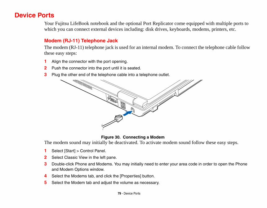
ipped with multiple ports to odems, printers, etc.
ct the telephone cable follow
ollow these easy steps.
e in order to open the Phone
79 - Device Ports
Device PortsYour Fujitsu LifeBook notebook and the optional Port Replicator come equwhich you can connect external devices including: disk drives, keyboards, m
Modem (RJ-11) Telephone JackThe modem (RJ-11) telephone jack is used for an internal modem. To connethese easy steps:
1 Align the connector with the port opening.
2 Push the connector into the port until it is seated.
3 Plug the other end of the telephone cable into a telephone outlet.
Figure 30. Connecting a ModemThe modem sound may initially be deactivated. To activate modem sound f1 Select [Start] > Control Panel.
2 Select Classic View in the left pane.
3 Double-click Phone and Modems. You may initially need to enter your area codand Modem Options window.
4 Select the Modems tab, and click the [Properties] button.
5 Select the Modem tab and adjust the volume as necessary.

000Base-T) Ethernet LAN icular network. (Please refer .) To connect the LAN cable
YSTEMS. DO NOT CONNECT AMAGE TO THE INTERNAL
MANUFACTURER’S TEMS. BE SURE TO FIND OUT
XIMUM SPEED OF 53000BPS IS THE ON THE LINE CONDITIONS. THE
CERTIFIED FOR USE IN THE UNITED ES.
LAN Device
80 - Device Ports
Internal LAN (RJ-45) JackThe internal LAN (RJ-45) jack is used for a Gigabit (10Base-T/100Base-Tx/1connection. You may need to configure your notebook to work with your partto your network administrator for information on your network configurationfollow these easy steps:
THE INTERNAL MODEM IS NOT INTENDED FOR USE WITH DIGITAL PBX STHE INTERNAL MODEM TO A DIGITAL PBX AS IT MAY CAUSE SERIOUS DMODEM OR YOUR ENTIRE LIFEBOOK NOTEBOOK. CONSULT YOUR PBXDOCUMENTATION FOR DETAILS. SOME HOTELS HAVE DIGITAL PBX SYS
BEFORE YOU CONNECT YOUR MODEM.
• THE INTERNAL MODEM IS DESIGNED TO THE ITU-T V.90 STANDARD. ITS MA
HIGHEST ALLOWED BY FCC, AND ITS ACTUAL CONNECTION RATE DEPENDS
MAXIMUM SPEED IS 33600BPS AT UPLOAD.
• THE INTERNAL MODEM ON ALL LIFEBOOK NOTEBOOKS FROM FUJITSU ARE STATES AND CANADA. THE MODEM MAY BE CERTIFIED IN OTHER COUNTRI
1 Align the connector with the port opening.
2 Push the connector into the port until it is seated.
3 Plug the other end of the cable into a LAN outlet.
Figure 31. Connecting

such as external game pads, n your notebook: one on the
then push the connector into
e)
speakers to your notebook. ini-plug. In order to connect
DS, NOT ALL USB DEVICES
81 - Device Ports
Universal Serial Bus PortsThe Universal Serial Bus 2.0 ports (USB) allow you to connect USB devicespointing devices, keyboards and/or speakers. There are five USB 2.0 ports oright side and four on the rear.
In order to connect a USB device, align the connector with the port opening, the port until it is seated.
Figure 32. Connecting a USB Device to System (rear and right sid
Headphone JackThe headphone jack allows you to connect headphones or powered externalYour headphones or speakers must be equipped with a 1/8” (3.5 mm) stereo mheadphones or speakers follow these easy steps: 1 Align the connector with the port opening.
2 Push the connector into the port until it is seated.
DUE TO THE ONGOING CHANGES IN USB TECHNOLOGY AND STANDAR
AND/OR DRIVERS ARE GUARANTEED TO WORK.
USB Ports

our microphone must be hone jack of your notebook.
jector. In order to connect an
EO SPEAKERS WILL BE
External Video Device
82 - Device Ports
Microphone JackThe microphone jack allows you to connect an external mono microphone. Yequipped with a 1/8”(3.5 mm) mono mini-plug in order to fit into the micropIn order to connect a microphone follow these easy steps:
1 Align the connector with the port opening.
2 Push the connector into the port until it is seated.
External Video PortThe external video port allows you to connect an external monitor or LCD proexternal video device, follow these easy steps:
IF YOU PLUG HEADPHONES INTO THE HEADPHONE JACK, BUILT-IN STER
DISABLED.
1 Align the connector with the port opening.
2 Push the connector into the port until it is seated.
3 Tighten the two hold-down screws, located on each end of the connector.
Figure 33. Connecting an

ant with IEEE 1394 standard. t can allow up to 400 Mbps evice with the 1394 port.
ELECTION OF WHERE TO SEND N, YOU WILL STEP TO THE NEXT G TO THE EXTERNAL MONITOR
N EXTERNAL MONITOR.
ATION. IF YOU INTEND TO OU WILL NEED TO PURCHASE AN
n IEEE 1394 Device
83 - Device Ports
IEEE 1394 PortThe 4-pin 1394 port allows you to connect digital devices that are compliThe IEEE 1394 standard is easy to use, connect, and disconnect. This portransfer rate. A third-party application is required to operate your digital d
PRESSING THE [FN] + [F10] KEYS ALLOWS YOU TO CHANGE YOUR SYOUR DISPLAY VIDEO. EACH TIME YOU PRESS THE KEY COMBINATIO
CHOICE, STARTING WITH THE BUILT-IN DISPLAY PANEL ONLY, MOVIN
ONLY, FINALLY MOVING TO BOTH THE BUILT-IN DISPLAY PANEL AND A
THE 1394 PORT USED IN THIS SYSTEM USES A FOUR-PIN CONFIGUR
INTERFACE WITH DEVICES WHICH USE A SIX-PIN CONFIGURATION, YADAPTER.
In order to connect a 1394 device, follow these steps: 1 Align the connector with the port
opening.
2 Push the connector into the port until it is seated.(Figure 34)
Figure 34. Connecting a

Video Jack
84 - Device Ports
S-Video Out Port
The S-Video port allows you to connect and use directly any S-Video device, such as a VCR or television. (Note that the S-Video interface supports video only, not audio.) The S-Video standard provides for a higher quality picture than Composite. In order to connect an S-Video device, follow these easy steps: (Figure 35)
1 Align the connector with the port opening.
2 Push the connector into the port until it is seated. Figure 35. S-

Troubms that you can solve on the device. The information in s and identify failures that
ng complex troubleshooting:
ower source.
also remove the card from the
n properly. You can also
u turn it back on.
85
Chapter 4
Troubleshooting Your LifeBook
leshootingThere may be occasions when you encounter simple setup or operating problespot, or problems with peripheral devices that can be solved by replacing thethis section helps you isolate and resolve some of these straightforward issuerequire service.
Identifying the ProblemIf you encounter a problem, go through the following procedure before pursui1 Turn off your LifeBook notebook.
2 Make sure the AC adapter is plugged into your notebook and to an active AC p
3 Make sure that any card installed in the PC Card slot is seated properly. You canslot, thus eliminating it as a possible cause of failure.
4 Make sure that any devices connected to the external connectors are plugged idisconnect such devices, thus eliminating them as possible causes of failure.
5 Turn on your notebook. Make sure it has been off at least 10 seconds before yo
6 Go through the boot sequence.

t follows, for more detailed
t success, contact your support
so that the customer support
ation and serial numbers.
ORT REPRESENTATIVE MAY BE ESTIONS OVER THE PHONE.
86 - Troubleshooting
7 If the problem has not been resolved, refer to the Troubleshooting Table, thatroubleshooting information.
8 If you have tried the solutions suggested in the Troubleshooting Table withourepresentative:
Toll free: 1-800-8Fujitsu (1-800-838-5487) E-mail: [email protected] Web site: http://www.computers.us.fujitsu.com/support.
Before you place the call, you should have the following information readyrepresentative can provide you with the fastest possible solution:
• Product name• Product configuration number• Product serial number• Purchase date• Conditions under which the problem occurred• Any error messages that have occurred• Type of device connected, if any
See the Configuration Label on the bottom of your notebook for configur
IF YOU KEEP NOTES ABOUT WHAT YOU HAVE TRIED, YOUR SUPP
ABLE TO HELP YOU MORE QUICKLY BY GIVING ADDITIONAL SUGG

mptoms under the Problem ou will find a description of hat, if anything, you can do to tions may not apply to your
Page
page 91
. . . . . . . . . page 91
lems. . . . . . page 91
. . . . . . . . . . page 92
Problems . page 94
. . . . . . . . . . page 95
ms. . . . . . . . page 97
87 - Troubleshooting
Specific Problems
Using the Troubleshooting Table
When you have problems with your LifeBook notebook, try to find the sycolumn of the troubleshooting table for the feature giving you difficulty. Ycommon causes for that symptom under the column Possible Cause and wcorrect the condition under Possible Solutions. All possible causes or solunotebook.
Troubleshooting Table
Problem Page
Audio Problems . . . . . . . . . . . . . . . . . . page 88
DVD/CD-ROM Drive Problems . . . . . . page 88
Floppy Disk Drive Problems . . . . . . . . page 89
Hard Drive Problems . . . . . . . . . . . . . . page 90
Keyboard or Mouse Problems . . . . . . . page 90
Memory Problems . . . . . . . . . . . . . . . . page 91
Problem
Modem Problems
USB Device Problems
PC/ExpressCard Prob
Power Failures . . . . .
Shutdown and Startup
Video Problems . . . .
Miscellaneous Proble

r notebook and operating system. n on your keyboard. Pressing [F9] ll increase the volume of your
i.e. keyboard "hot keys") should f the operating (see above). If that volume control settings in your
s the built-in speakers, remove
ed or reinstalled by using the Driv-me with your Fujitsu LifeBook. erating system documentation for
tool tray on the bottom right of the . If the Mute box is checked, click use the [Fn+F3] key combination Pressing [F3] while holding [Fn]
stall the disc properly.
drive tray until it latches. If that ar drive latch to remove the device drive until it latched; this ensures .
88 - Troubleshooting
Problem Possible Cause Possible Solutions
Audio Problems
There is no sound coming from the built-in speakers.
The volume is turned too low.
Adjust the volume control on youUse the [Fn+F9] key combinatiorepeatedly while holding [Fn] winotebook.
The software volume control is set too low.
Manually adjusting the volume (dynamically adjust the volume odoesn’t work, adjust the sound software or application.
Headphones are plugged into your notebook.
Plugging in headphones disablethe headphones.
Software driver is not configured correctly.
The Audio Driver may be installers and Applications CD that caRefer to your application and ophelp.
The speakers have been muted using the Volume icon in the sys-tem tray.
Click on the Volume icon in the screen. (It looks like a speaker)on it to uncheck it. You can alsoto toggle the volume on and off.will toggle the audio mute.
DVD/CD-RW/CD-ROM Drive Problems
LifeBook notebook fails to recognize DVD/CD-RW/CD-ROM’s.
The disc is not pushed down onto raised center circle of the drive.
Open optical drive tray and re-in
Optical drive tray is not latched shut.
Push on the front of the optical doesn’t work, pull out the modulfrom the bay, then re-insert the that the drive is properly seated

e “Media Player Software” on
by the application is the same as stem. When the operating system
designations are automatically ignation can be changed with the t Administrative Tools > Computer
ve CD cleaning cloth and reinsert. DVD/CD-RW/CD-ROM in the
ay disable this feature.
enable.
ion and re-insert.
y disk drive.
ity settings.
89 - Troubleshooting
LifeBook notebook fails to recognize DVD/CD-RW/CD-ROM’s.(continued)
Incorrect DVD Player or no DVD Player soft-ware is installed.
Install DVD Player software. (Sepage 62.for more information.)
Wrong drive designator was used for the disc in the application.
Verify the drive designator usedthe one used by the operating syis booted from a DVD/CD, driveadjusted. Note that the drive desDisk Management tool located aManagement.
DVD/CD-RW/CD-ROM is dirty or defective.
Wipe the disc with a non-abrasiIt if still will not work try anotherdrive.
The drive access indicator on the Status Indicator Panel blinks at regular inter-vals with no disc in the tray or the drive is not installed.
The Windows auto insertion function is active and is checking to see if a disc is ready to run.
This is normal. However, you m
Floppy Disk Drive Problems
You cannot access your optional external floppy disk.
You tried to write to a write protected floppy disk.
Eject the disk and set it to write
Disk is not loaded cor-rectly.
Eject floppy disk, check orientat
The floppy disk drive may not be properly installed.
Remove and re-install your flopp
Security is set to protect access to floppy disk data.
Verify your password and secur
Problem Possible Cause Possible Solutions

pplication is in use by the operat-system is booted from a CD, drive djusted.
ty settings.
me button.
g device to restart your system.
ice Ports” on page 79.
g system documentation and acti-
g system documentation and acti-
90 - Troubleshooting
Hard Drive Problems
You cannot access your hard drive.
The wrong drive desig-nator was used by an application when a bootable disc was used to start the notebook.
Verify drive designator used by aing system. When the operating designations are automatically a
Security is set so your operating system can-not be started without a password.
Verify your password and securi
Keyboard or Mouse Problems
The built-in keyboard does not seem to work.
The notebook has gone into Standby mode.
Push the Power/Suspend/Resu
Your application has locked out your key-board.
Try to use your integrated pointin
You have installed an exter-nal keyboard or mouse, and it does not seem to work.
Your external device is not properly installed.
Re-install your device. See “Dev
Your operating system software is not set up with correct software driver for that device.
Check your device and operatinvate the proper driver.
You have connected an external keyboard or a mouse and it seems to be locking up the system.
Your operating system software is not setup with correct software driver for that device.
Check your device and operatinvate the proper driver.
Your system has crashed.
Try to restart your notebook. I
Problem Possible Cause Possible Solutions

mory upgrade module. ” on page 75.
POST) messages. ages” on page 98.
ocumentation for additional infor-
e. See “Device Ports” on page 79.
rt your notebook.
ion and activate the correct driver.
. See “PC Cards/ExpressCards™”
91 - Troubleshooting
Memory Problems
Your System Properties screen does not show the correct amount of installed memory.
Your memory upgrade module is not properly installed.
Remove and re-install your meSee “Memory Upgrade Module
You have a memory failure.
Check for Power On Self Test (See “Power On Self Test Mess
Modem Problems
Messages about modem operation.
Messages about modem operation are generated by which-ever modem applica-tion is in use.
See your application software dmation.
USB Device Problems
You have installed a USB device. Your LifeBook note-book does not recognize the device, or the device does not seem to work properly.
The device is not prop-erly installed.
Remove and re-install the devic
The device may have been installed while an application was running, so your notebook is not aware of its installation.
Close the application and resta
Your device may not have the correct soft-ware driver active.
See your software documentat
PC/ExpressCard Problems
A card inserted in the PC Card slot or ExpressCard slot does not work or is locking up the system.
The card is not properly installed.
Remove and re-install the cardon page 68.
Problem Possible Cause Possible Solutions

t your notebook.
n and activate the correct driver.
l to determine the presence and Status Indicator Panel” on y or a Power adapter.
o verify the presence and condi-is indicating a short, remove that r power source or replace that
l to determine the presence and Status Indicator Panel” on o operate until a battery is tery.
cted correctly. See “Power
install a charged optional second
92 - Troubleshooting
A card inserted in the PC Card slot or ExpressCard slot does not work or is locking up the system.(continued)
The card may have been installed while an application was running, so your notebook is not aware of its installation.
Close the application and restar
Your software may not have the correct soft-ware driver active.
See your software documentatio
Power Failures
You turn on your LifeBook notebook and nothing seems to happen.
The installed primary battery is completely discharged, there is no optional second battery installed or there is no Power adapter (AC or Auto/Airline) installed.
Check the Status Indicator Panecondition of the batteries. See “page 27.Install a charged batter
The primary battery is installed but is faulty.
Use the Status Indicator panel ttion of the batteries. If a battery battery and operate from anothebattery.
The battery or batteries are low.
Check the Status Indicator Panecondition of the batteries. See “page 27. Use a Power adapter tcharged or install a charged bat
The power adapter (AC or auto/airline) is not plugged in properly.
Verify that your adapter is conneSources” on page 42.
The Power adapter (AC or auto/airline) is faulty.
Try a different Power adapter orbattery.
Problem Possible Cause Possible Solutions

utlet, check for a line switch or outlet. If you are using an e sure the ignition switch is in the
d, or move the mouse to restore ower/Suspend/Resume button.
settings, or close your applica-s Properties located in the Con-alues to better suit your needs.
push the Power/Sus-er Sources” on page 42.
ies using the Status Indicator y batteries that are shorted. See 27.
d in and the outlet has power.
ed one or install a power adapter.
erly connected by re-installing
93 - Troubleshooting
You turn on your LifeBook notebook and nothing seems to happen.
(continued)
The Power adapter (AC or auto/airline) has no power from the AC out-let, airplane jack, or the car’s cigarette lighter.
Move the AC cord to a different otripped circuit breaker for the ACauto/airline adapter in a car makOn or Accessories position.
Your LifeBook notebook turns off all by itself.
The power manage-ment parameters are set for auto timeouts which are too short for your operating needs.
Press any button on the keyboaroperation. If that fails, push the PCheck your power managementtions and go to the Power Optiontrol Panel to adjust the timeout v
You are operating on battery power and ignored a low battery alarm until the batteries are at the dead battery state and the system has gone into Dead Bat-tery Suspend mode.
Install a power adapter and thenpend/Resume button. See “Pow
You have a battery fail-ure.
Verify the condition of the batterpanel, and replace or remove an“Status Indicator Panel” on page
Your adapter has failed or lost its power source.
Make sure the adapter is plugge
Your LifeBook notebook will not work on battery alone.
The installed battery is dead.
Replace the battery with a charg
No batteries are installed.
Install a charged battery.
The batteries are improperly installed.
Verify that the batteries are propthem.
Problem Possible Cause Possible Solutions

ies using the Status Indicator y batteries that are shorted. See 27.
d an optional second battery his application when at all
settings and adjust according to
ment. The higher the brightness s.
operating temperature. Charging el will flash when battery is out-
r Options, select the “Choose ion and make your choices.
button again.
94 - Troubleshooting
Your LifeBook notebook will not work on battery alone.(continued)
Your installed batteries are faulty.
Verify the condition of the batterpanel and replace or remove an“Status Indicator Panel” on page
The batteries seem to discharge too quickly.
You are running an application that uses a lot of power due to fre-quent hard drive access or optical drive access, or use of a modem, LAN PC card, Wireless LAN, or Bluetooth device.
Use both the primary battery anand/or use a power adapter for tpossible.
The power savings fea-tures may be disabled.
Check the Power Options menu your operating needs.
The brightness is turned all the way up.
Turn down the brightness adjustthe more power your display use
The batteries are old. Replace the batteries.
The batteries have been exposed to high temper-atures.
Replace the batteries.
The batteries are too hot or too cold.
Restore the notebook to normal icon on the Status Indicator panside of operating range.
Shutdown and Startup Problems
The Suspend/Resume button does not work.
Suspend/Resume button is disabled.
In the Control Panel under Powewhat the power button does” opt
There may be applica-tion software. conflict
Close all applications and try the
Problem Possible Cause Possible Solutions

sing the [ESC] key while the he [F2] key and enter the setup ngs from the Boot menu. See
sword. Enter the setup utility and odify them as accordingly. See
ST) messages to determine the lem. Not all messages are errors; s. See “Power On Self Test Mes-
nges And Exit when exiting the
for presence of the Security icon. d See “Status Indicator Panel” on
n the [Fn] key allows you to o send your display video. Each step to the next choice. The lay only, external monitor only,
monitor.
ess control until you have ade-e [F6] or [F7] keys while holding u to change the brightness level
95 - Troubleshooting
The system powers up, and displays power on informa-tion, but fails to load the operating system.
The boot sequence set-tings of the setup utility are not compatible with your configuration.
Set the operating source by presFujitsu logo is on screen or use tutility and adjust the source setti“BIOS Setup Utility” on page 48.
You have a secured system requiring a password to load your operating system.
Make sure you have the right pasverify the Security settings and m“BIOS Setup Utility” on page 48.
An error message is dis-played on the screen during the notebook (boot) sequence.
Power On Self Test (POST) has detected a problem.
See the Power On Self Test (POmeaning and severity of the probsome are simply status indicatorsages” on page 98.
Your notebook appears to change setup parameters when you start it.
BIOS setup changes were not saved when made and you exited the setup utility.
Make sure you select Save ChaBIOS setup utility.
Your system display won’t turn on when the system is turned on or has resumed.
You have installed the LifeBook/Security Appli-cation panel.
Check the Status Indicator PanelIf it is visible, enter your passworpage 27.
Video Problems
The built-in display is blank when you turn on your Life-Book notebook.
The notebook is set for an external monitor only.
Pressing [F10] while holding dowchange your selection of where ttime you press the keys you will choices, in order are: built-in dispboth built-in display and external
The display angle and brightness settings are not adequate for your lighting conditions.
Move the display and the brightnquate visibility. Pressing either thdown the [Fn] key also allows yoof the display.
Problem Possible Cause Possible Solutions

e the mouse to restore operation. pend/Resume button. (The display de, Auto Suspend or Video Time-
tative.
rd, or move the mouse to restore Power/Suspend/Resume button. t settings, or close your applica-gs menu of the setup utility to ter suit your operation needs.
rd, or move the mouse to restore ower/Suspend/Resume button.
Standby Mode, Auto Suspend or
l to verify that the Security icon is ur password.
the keyboard.
96 - Troubleshooting
The built-in display is blank when you turn on your Life-Book notebook.(continued)
Power management timeouts may be set for short intervals and you didn’t notice the display come on and go off.
Press a keyboard button or movIf that fails, push the Power/Susmay be shut off by Standby moout)
The notebook turned on with a series of beeps and the built-in display is blank.
Power On Self Test has detected a failure which does not allow the dis-play to operate.
Contact your support represen
The display goes blank by itself after you have been using it.
The notebook has gone into Video timeout, Standby mode, or Save-to-Disk mode because you have not used it for a period of time.
Press any button on the keyboaoperation. If that fails, push theCheck your power managementions and go to the Power Savinadjust the timeout values to bet
Power management timeouts may be set for short intervals and you didn’t notice the display come on and go off.
Press any button on the keyboaoperation. If that fails, push the P(The display may be shut off byVideo Timeout)
Your display won’t turn on when the system is turned on or when it has resumed.
The system may be password-protected.
Check the status indicator paneblinking. If it is blinking, enter yo
The Built-in Display does not close.
A foreign object, such as a paper clip, is stuck between the display and keyboard.
Remove all foreign objects from
The display has bright or dark spots.
If spots are tiny and few, this is normal for a large LCD display.
This is normal; do nothing.
Problem Possible Cause Possible Solutions

support representative.
clearer but smaller display for appli-e system’s native pixel resolution. ve less resolution by changing dis-hese settings can be changed in the
brightness or double-click on the bat- Control under battery settings.
xternal Video Port” on page 82.
ting system documentation and acti-
tion and the External Monitor Sup-ions section. See “Specifications” on
and help displays screens for sages are errors some may simply
97 - Troubleshooting
The display has bright or dark spots.(continued)
If spots are numerous or large enough to inter-fere with your operation needs.
Display is faulty; contact your
The application display uses only a portion of your screen and is surrounded by a dark frame.
You are running an app-lication that doesn’t support the system’s native pixel resolution and display compres-sion is enabled.
Display compression gives acations that do not support thYou can fill the screen but haplay compression settings. TIntel GMA control panel.
The Display is dark when on battery power.
The Power Manage-ment utility default is set on low brightness to conserve power.
Press [Fn] + [F7] to increase tery gauge and adjust Power
You have connected an external monitor and it does not display any information.
Your external monitor is not properly installed.
Reinstall your device. See “E
Your operating system is not setup with the correct software driver for that device.
Check your device and operavate the proper driver.
You have connected an external monitor and it does not come on.
Your external monitor is not compatible with your LifeBook notebook.
See your monitor documentaport portions of the Specificatpage 119.
Miscellaneous Problems
Error message is displayed on the screen during the operation of an application.
Application software often has its own set of error message displays.
See your application manual more information. Not all mesbe status.
Problem Possible Cause Possible Solutions

ix BIOS and/or your operating re marked with an *. If an error erating system documentation ge and its meaning is not clear,
ested by the Power On Self
tte tests. Check to see that the “BIOS Setup Utility” on rive is properly defined and
e an installed memory upgrade stalled, you may want to check il you can contact your support
.
98 - Troubleshooting
Power On Self Test MessagesThe following is an alphabetic list of error-and-status messages that Phoensystem can generate and an explanation of each message. Error messages amessage is displayed that is not in this list, write it down and check your opboth on screen and in the manual. If you can find no reference to the messacontact your support representative for assistance.
nnnn Memory Cache Passed
Where nnnn is the amount of system cache in kilobytes successfully tTest. (This can only appear if you have an SRAM PC Card installed.)
Floppy Disk drive A error or Floppy Disk drive B error
Drive A: or B: is present but fails the BIOS Power On Self Test diskedrive is defined with the proper diskette type in the Setup Utility, (Seepage 48.) and that the diskette drive is installed correctly. If the disk dinstalled, avoid using it and contact your support representative.
*Extended Memory Failed at address line: xx
Extended memory not working or not configured properly. If you havmodule, verify that the module is properly installed. If it is properly inyour Windows Setup to be sure it is not using unavailable memory untrepresentative.
nnnn Extended RAM Passed
Where nnnn is the amount of memory in kilobytes successfully tested
an that the hard drive type the Power On Self Test. Run m if necessary. If the settings be a serious fault which might tive.
at the floppy disk drive type the Power On Self Test. Run
at the floppy disk drive type the Power On Self Test. Run
essage you may have some pport representative for more
ard or keyboard controller but rt representative.
ard controller but may be able tive.
99 - Troubleshooting
*Failure Fixed Disk n (where x=1-4)
The fixed disk is not working or not configured properly. This may meidentified in your setup utility does not agree with the type detected bythe setup utility to check for the hard drive type settings and correct theare OK and the message appears when you restart the system, there may cause you to lose data if you continue. Contact your support representa
*Incorrect Drive A type – run SETUP
Type of floppy drive A: not correctly identified in Setup. This means thidentified in your setup utility does not agree with the type detected bythe setup utility to correct the inconsistency.
*Incorrect Drive B type – run SETUP
Type of floppy drive B: not correctly identified in Setup. This means thidentified in your setup utility does not agree with the type detected bythe setup utility to correct the inconsistency.
*Invalid NVRAM Data
Problem with NVRAM access. In the unlikely case that you see this mdisplay problems. You can continue operating but should contact your suinformation.
*Keyboard controller error
The keyboard controller test failed. You may have to replace your keybomay be able to use an external keyboard until then. Contact your suppo
*Keyboard error
Keyboard not working. You may have to replace your keyboard or keyboto use an external keyboard until then. Contact your support representa

ey. You may have to replace ontact your support
s your BIOS is corrupted, run get this error, contact your
he setup utility and see if both uence is set correctly. Unless be on drive C:. If the setup
s and display it on the screen. a destroying failure. Contact
nd display it on the screen. If estroying failure. Contact
100 - Troubleshooting
*Stuck Key
BIOS discovered a stuck key and displays the scan code for the stuck kyour keyboard but may be able to use an external keyboard until then. Crepresentative.
*Monitor type does not match CMOS – Run SETUP
Monitor type not correctly identified in Setup. This error probably meanthe setup utility and set all settings to the default conditions. If you still support representative.
*Operating system not found
Operating system cannot be located on either drive A: or drive C: Enter tthe fixed disk, and drive A: are properly identified and that the boot seqyou have changed your installation greatly, the operating system shouldutility is correctly set, your hard drive may be corrupted.
*Parity Check 1 nnnn
Parity error found in the system bus. BIOS attempts to locate the addresIf it cannot locate the address, it displays ????. This is a potentially datyour support representative.
*Parity Check 2 nnnn
Parity error found in the I/O bus. BIOS attempts to locate the address ait cannot locate the address, it displays ????. This is a potentially data-dyour support representative.

ontinue the boot process or the
r On Self Test will load default correct values and they are not does not allow you to complete your support representative.
ur support representative.
as detected. You are risking data
tested.
of your BIOS and is a board u can continue operating but tup utility every time you turn
101 - Troubleshooting
*Press <F1> to resume, <F2> to SETUP
Displayed after any recoverable error message. Press the [F1] key to c[F2] key to enter Setup and change any settings.
*Previous boot incomplete – Default configuration used
Previous Power On Self Test did not complete successfully. The Powevalues and offer to run Setup. If the previous failure was caused by incorrected, the next boot will likely fail also. If using the default settingsa successful boot sequence, you should turn off the power and contact
*Real time clock error
Real-time clock fails BIOS test. May require board repair. Contact yo
*Shadow RAM Failed at offset: nnnn
Shadow RAM failed at offset nnnn of the 64k block at which the error wcorruption if you continue. Contact your support representative.
nnnn Shadow RAM Passed
Where nnnn is the amount of shadow RAM in kilobytes successfully
*System battery is dead – Replace and run SETUP
The BIOS CMOS RAM memory hold up battery is dead. This is part mounted battery which requires a support representative to change. Yoyou will have to use setup utility default values or reconfigure your seoff your notebook.
System BIOS shadowed
System BIOS copied to shadow RAM.

ps by an application program the system.
error was detected. This means , you risk corrupting your data.
y tested.
lty. Requires repair of system
102 - Troubleshooting
*System CMOS checksum bad – Default Configuration Used
BIOS CMOS RAM has been corrupted or modified incorrectly, perhathat changes data stored in BIOS memory. Run Setup and reconfigure
*System RAM Failed at offset: nnnn
System memory failed at offset nnnn of in the 64k block at which the that there is a fault in your built-in memory. If you continue to operateContact your support representative for repairs.
nnnn System Memory Passed
Where nnnn is the amount of system memory in kilobytes successfull
*System timer error
The timer test failed. The main clock that operates the computer is fauboard. Contact your support representative for repairs.
Video BIOS shadowed
Video BIOS successfully copied to shadow RAM.

ects the modem characteristics nternal modem operation is ation software. The standard
eep you informed of the actions ess display of the result codes.
alled refer to the application
103 - Troubleshooting
Modem Result CodesThe operating system and application software that is factory installed detand provides the necessary command strings to operate the modem. The icontrolled by generic AT commands from the operating system and appliclong form result codes may, in some cases, be displayed on your screen to kof your modem. The operating system and application software may suppr
Examples of result codes are:
• OK• NO CARRIER• NO DIALTONE• CONNECT 53000 (Connection complete
at 53,000 bps.)• ERROR• FAX• RING (This means an incoming call.)• BUSY• NO ANSWER
When using the internal modem with applications that are not factory instdocumentation.

ivers and Fujitsu utilities (in s documented below.
and/or applications that may
u Installer screen is displayed
ou can install from the Drivers
WEBSITE AT HE MOST CURRENT ND SYSTEM UPDATES.
LLED ON YOUR SYSTEM THAT NS CAN BE DOWNLOADED FROM
TALL STATUS. BLUE INDICATES E COMPONENT NEEDS TO BE
EADY INSTALLED; GREY ITEMS A REMINDER THAT THE
104 - Restoring Your Pre-installed Software
Restoring Your Pre-installed SoftwareThe Drivers and Applications Restore (DAR) DVD contains sets of device drspecific directories) that are unique to your computer configuration for use a
Re-installing Individual Drivers and ApplicationsThe Drivers and Applications CD can be used to selectively re-install drivers have been un-installed or corrupted.
To re-install drivers and/or applications:1 Boot up the system and insert the DAR CD after Windows has started. A Fujits
after the CD is inserted.
2 After reading the License Agreement, click [I agree].
3 A window will appear containing a list of applications, drivers, and utilities that yand Applications CD.
IF YOU HAVE ACCESS TO THE INTERNET, VISIT THE FUJITSU SUPPORT HTTP://WWW.COMPUTERS.US.FUJITSU.COM/SUPPORT TO CHECK FOR TINFORMATION, DRIVERS AND HINTS ON HOW TO PERFORM RECOVERY A
THERE MAY BE CERTAIN FREE THIRD-PARTY APPLICATIONS PRE-INSTA
ARE NOT ON THE DAR CD. THE LATEST VERSIONS OF THE APPLICATIO
THE THIRD-PARTY’S WEBSITE.
THE COMPONENTS LISTED ARE COLOR-CODED IN TERMS OF THEIR INS
THAT THE COMPONENT CAN BE INSTALLED. GREEN INDICATES THAT TH
INSTALLED SEPARATELY. GREY INDICATES A COMPONENT THAT IS ALR
CAN BE REINSTALLED, BUT PRIOR TO INSTALLATION YOU WILL RECEIVE
COMPONENT IS ALREADY INSTALLED.

ll all components, click [Select t select grey and green
ted Subsystems]; the
u want to reboot the system.
m (OS). The restored OS is r the OS is restored, you will plications Restore disc and ou purchased it.ata on your hard disk ete utility unless you are ing all partitions.n or resize existing s with this utility will cause
e status/condition by
d on a hidden drive. Other he hard disk has been
plet, perform the
105 - Restoring Your Pre-installed Software
4 In the list, check off all the components you want to install. If you want to instaAll]. Clicking [Select All] will select all of the blue-coded components; you muscomponents separately.
5 Once you have selected the components you wish to install, click [Install Seleccomponents will be installed.
6 After the components are installed, click [OK], then click [Yes] when asked if yo
Restoring the Operating System for Windows Vista SystemsThe Recovery and Utility disc contains four utilities:
• The Recovery utility allows you to restore the system operating systethe same one that was originally installed on the hard disk drive. Afteneed to reinstall the drivers and applications from the Drivers and Apfrom any application discs that were bundled with the system when y
• The Hard Disk Data Delete utility on this disc is used to delete all dand prevent it from being reused. Do not use the Hard Disk Data Delabsolutely certain that you want to erase your entire hard disk, includ
• The Partition Creation utility allows you to create a new D: partitiopartitions on your hard disk. NOTE: Creating or resizing partitionall data on the hard disk to be completely erased.
• The Diagnostics utility allows the IT professional to determine devicexecuting diagnostics tests on selected system components.
Methods for accessing the utilities
Certain LifeBook models have the Recovery and Utility applets pre-installesystems require that the Recovery and Utility disc be used (or in the event treformatted).
In order to determine the method for accessing the Recovery and Utility apfollowing procedures in order.

.
ption is present. If it is not g Recovery and Utility from the
loaded by powering on your en. The TrustedCore Menu will
bottom of the screen.
t, if necessary, then click [Next].
.
stics, in LifeBook/Stylistic models erating system, please insert function under the Recovery age 107.
PURCHASED.
106 - Restoring Your Pre-installed Software
Determining whether Recovery and Utility is pre-loaded
1 Turn on or reboot your system. When the Fujitsu logo appears, press [F12] key
2 From the Boot Menu that appears, check whether the <Recovery and Utility> opresent, it means that the utility must be used from the disc. Proceed to “Runnindisc” if <Recovery and Utility> is unavailable.
3 You can also use the TrustedCore menu to determine whether the utility is pre-system then pressing the {Enter] key when the Fujitsu logo appears on the screappear and the Recovery and Utility option will appear in the menu.
Running Recovery and Utility from hard disk
1 Cursor down to <Recovery and Utility> and press the [Enter] key.
2 While the files are being loaded from the disc, a progress bar will appear at the
3 When the System Recovery Options dialog opens, select a new keyboard layou
4 When the Operating System dialog appears, click [Next].
5 If necessary, enter your password, then click [OK].
6 When System Recovery Options window appears, click on Recovery and Utility
7 The Recovery and Utility screen appears on the screen with three tabs: DiagnoRecovery and Utility. Please note that Diagnostics tab is not supported on certawhen running Recovery and Utility from the hard disk. In order to restore the opthe “Recovery and Utility” disc in the CD/DVD drive and use the Start Recoverytab. For more information about the tabs, go to “Recovery and Utility tabs” on p
Running Recovery and Utility from the disc
THIS DISC CAN ONLY BE USED WITH THE SYSTEM WITH WHICH IT WAS
ot from the optical drive. To e or an external floppy disk
[Enter] key or click on the left
or attached externally to it, and
appears. On the screen are
ls. It is not likely you will hen click [Execute], several
the recovery process erases ck up all data that you don’t
while running the recovery he [Execute] button, then
Data Delete and Partition
107 - Restoring Your Pre-installed Software
BOOT Priority Change
Before restoring an image, you must first verify that the system is set up to boverify/change the boot-up priority (rather than booting-up from the hard drivdrive), perform the following steps:
1 Power on your system. When the Fujitsu logo appears on the screen. press themouse or touchpad button; the TrustedCore Menu will appear.
2 Select the Boot Menu from the TrustedCore Menu.
3 Highlight the CD/DVD option, then click [OK].
Procedure
1 Ensure that you have a device that can read CDs either installed in your system that it has been set up as the Boot device.
2 Turn on the power to your system.
3 Insert the Recovery and Utility Disc into the drive tray.
4 Reboot your system. After the system reboots, the Recovery and Utility screenthree tabs: Diagnostics, Recovery, and Utility.
Recovery and Utility tabs
Diagnostics tab: The Diagnostics tool is designed for use by IT professionaneed to use this tool. When you select devices from the Diagnosis window ttests are performed on the selected components.
Recovery tab: The Recovery tab contains the Start Recovery tool. Note thatall data from the C: drive. If you decide to use the recovery tool, be sure to bawant to lose. Also note that you must run the system using your AC adaptertool. To use the Recovery tool, select the Start Recovery function, click on tfollow the instructions on the screen.
Utility tab: The Utility tab contains three tools: System Restore, Hard DiskCreation.

omputer run slowly or stop to an earlier restore point, and ata.
hard disk and prevent the data e utility unless you are including all partitions.r resize existing partitions on utility will cause all data on
) utility. With FDU, you can updates for your system.
screen (roll the cursor over the y, go to [Start] > All Programs, .
old the pen on the icon for a g items:
prompted to agree to a user ith the Fujitsu site to check for through it, indicating that it plete, a message appears
every 3 days).
108 - Restoring Your Pre-installed Software
• System Restore can help fix problems that might be making your cresponding. System Restore enables you in rolling back the systemdoes not affect any of your documents, pictures, or other personal d
• The Hard Disk Data Delete utility is used to delete all data on thefrom being reused. NOTE: Do not use the Hard Disk Data Deletabsolutely certain that you want to erase your entire hard disk,
• The Partition Creation utility allows you to create a D: partition oyour hard disk. NOTE: Creating or resizing partitions with this the hard disk to be completely erased.
Automatically Downloading Driver UpdatesYour system has a convenient tool called the Fujitsu Driver Update (FDUchoose to automatically or manually go to the Fujitsu site to check for new
The FDU icon should appear in the system tray at the bottom right of youricons to find the correct one). If the icon does not appear in the system traand click on Fujitsu Driver Update; this will create the icon automatically
To invoke the FDU menu, you can either right-click on the FDU icon or hcouple of seconds until the menu appears. The menu contains the followin
Check for updates now
Allows for manual driver update search. The first time it is used, you are agreement. After clicking on the icon, the FDU automatically connects wupdates and downloads them. While downloading, the icon has a red bar cannot be used while the download is in process. When the update is cominforming you of the fact.
Enable Automatic Update Notifications
Automatically searches for new updates on a regular basis (approximately

via the FDU.
109 - Restoring Your Pre-installed Software
Show update history
Brings up a screen that displays a history of updates that have been made
About Fujitsu Driver Update
Displays the FDU version number and copyright information
Fujitsu Driver Update Readme
Displays the FDU readme.

Carin life and reliability. This section
BY ELECTROSTATIC DISCHARGE (ESD). CAUTIONS:
HEN USING A PORT REPLICATOR), IT IS CT TO DISCHARGE STATIC ELECTRICITY
EMOVING SYSTEM COMPONENTS. EVEN LD BE LOST OR MEMORY COULD BE
Y THE EDGE SO AS NOT TO TOUCH ANY L COMPUTER TERMINALS OR ORT TO THE COMPONENTS.
OF THIS PRODUCT OR SIMILAR CHILDREN ACCESS TO THE INTERIOR OF CABLES.
110
Chapter 5
Care and Maintenance
g for your LifeBook NotebookIf you use your Fujitsu LifeBook notebook carefully, you will increase itsprovides some tips for looking after the notebook and its devices.
• THE SYSTEM CONTAINS COMPONENTS THAT CAN BE SEVERELY DAMAGED
TO MINIMIZE RISK TO THE COMPONENTS, OBSERVE THE FOLLOWING PRE
• BEFORE DOCKING OR UNDOCKING YOUR LIFEBOOK NOTEBOOK (WA GOOD PRACTICE TO ALWAYS TOUCH A GROUNDED METAL OBJE
BUILT UP IN YOUR BODY.
• BE SURE TO POWER DOWN YOUR SYSTEM BEFORE ADDING OR RIF THE SYSTEM IS IN HIBERNATE OR STANDBY STATES, DATA COU
DAMAGED IF POWER IS STILL AVAILABLE TO THE SYSTEM.
• WHEN INSTALLING OR REMOVING A MEMORY MODULE, HOLD IT BCONTACTS OR CHIPS. BE CAREFUL NOT TO TOUCH ANY INTERNA
COMPONENTS; THE OIL FROM YOUR FINGERS COULD CAUSE A SH
• ELECTRICAL EQUIPMENT MAY BE HAZARDOUS IF MISUSED. OPERATIONS
PRODUCTS, MUST ALWAYS BE SUPERVISED BY AN ADULT. DO NOT ALLOW
ANY ELECTRICAL PRODUCTS AND DO NOT PERMIT THEM TO HANDLE ANY

reat it with respect and care.
llation instructions closely.
ance, be sure to keep all air eriodic cleaning, depending
cted, such as in tight
tive.
r a bathtub, swimming pool).otebook.
as temperatures above 140°
in use.
er carrying case, make sure
the weight of the notebook.
111 - Caring for your LifeBook Notebook
• Your LifeBook notebook is a durable but sensitive electronic device. T• Make a habit of transporting it in a suitable carrying case.• Do not attempt to service the computer yourself. Always follow insta• Keep it away from food and beverages.• To protect your notebook from damage and to optimize system perform
all vents unobstructed, clean, and clear of debris. This may require pupon the environment in which the system is used.
• Do not operate the notebook in areas where the air vents can be obstruenclosures or on soft surfaces like a bed or cushion.
• If you accidentally spill liquid on your LifeBook notebook:1 Turn it off.
2 Position it so that the liquid can run out.
3 Let it dry out for 24 hours, or longer if needed.
4 If your notebook will not boot after it has dried out, call your support representa
• Do not use your Fujitsu LifeBook notebook in a wet environment (nea• Always use the AC adapter and batteries that are approved for your n• Avoid exposure to sand, dust and other environmental hazards.• Do not expose your notebook to direct sunlight for long periods of time
F (60° C) may damage your notebook.• Keep the covers closed on the connectors and slots when they are not• Do not put heavy or sharp objects on the computer.• If you are carrying your LifeBook notebook in a briefcase, or any oth
that there are no objects in the case pressing on the lid.• Never position your notebook such that the optical drive is supporting

use abrasives or solvents.aners.ove the battery when cleaning
products:
soft, lint-free cloth until the
ff-the-shelf products:
tebook LCD displays.
puter.
112 - Caring for your LifeBook Notebook
Cleaning your LifeBook notebook• Always disconnect the power plug. (Pull the plug, not the cord.)• Clean your LifeBook notebook with a damp, lint-free cloth. Do not• Use a soft cloth to remove dust from the screen. Never use glass cle• Always shut down the computer, unplug the power adapter, and rem
or disinfecting the computer exterior, keyboard or LCD display. NOTE: Avoid wetting the thermal suede in all cases.
Cleaning guidelines using recommended off-the-shelf cleaners
Computer exterior, computer keyboard
To clean the exterior and keyboard, use one of the following off-the-shelf
• Office Depot® #154-616 Notebook Cleaning Kit• Meridrew Enterprises Klear_Screen® Wipes• 3M CL563 Cleaner Wipes
Note: After cleaning with one of these products, gently polish with a dry, solution is no longer visible.
LCD display
To clean the LCD display or fingerprint sensor, use one of the following o
• Office Depot® #154-616 Notebook Cleaning Kit• Meridrew Enterprises Klear_Screen® Wipes
* Applies to Tablet PC, convertible PC with LCD shield, and standard no
Wipe the LCD surface gently, allowing it to dry before turning on the com
/

use another ethanol-based EPA.
tebook off, fully charge the
ok with a battery installed, , a faulty battery might
uld remain between 13ºF
HE LCD AND/OR DAMAGE TO THE ES AND MATERIAL SAFETY DATA
ICALS SUCH AS PAINT THINNER, GE SURFACE FINISHES AND THE
CS.
KAGING IT. AFTER SHUTTING DOWN CONDITION (I.E., NO LIGHTS ARE
FF OR HIBERNATE MODE WHEN YOU ORD SECURITY SETTINGS OR SOME
AGE THE NOTEBOOK DUE TO SHOCK .
113 - Caring for your LifeBook Notebook
Disinfecting LifeBook computers
• Wipe the surface with a soft cloth wipe and a 50% ethanol solution orgermicide which has been registered as a hospital disinfectant by the
Storing your LifeBook notebook• If storing your notebook for a month or longer, turn your LifeBook no
battery, then remove and store all Lithium ion batteries.• Store your notebook and batteries separately. If you store your LifeBo
the battery will discharge, and battery life will be reduced. In additiondamage your LifeBook.
• Store your Fujitsu LifeBook in a cool, dry location. Temperatures sho(-25ºC) and 140ºF (60ºC).
• USE OF INCORRECT CLEANERS CAN RESULT IN OPTICAL IMPAIRMENT OF TCOMPUTER. ALWAYS REFER TO THE CLEANER MANUFACTURER'S GUIDELIN
SHEETS FOR PROPER HANDLING AND USE OF THE PRODUCTS.
• NEVER USE AMMONIA, ACIDIC, OR ALKALINE CLEANERS OR ORGANIC CHEM
ACETONE, PROPYL OR ISOPROPYL ALCOHOL, OR KEROSENE. IT MAY DAMA
COATING OF THE LCD SCREEN.
• NEVER USE COMPRESSED AIR FOR CLEANING STYLISTIC AND LIFEBOOK P
• ALWAYS POWER OFF THE COMPUTER BEFORE TRANSPORTING AND/OR PAC
THE SYSTEM, WAIT UNTIL THE STATUS LED PANEL INDICATES POWER OFF
ILLUMINATED).
• IT IS POSSIBLE THAT THE UNIT MAY NOT AUTOMATICALLY GO TO POWER OCLOSE THE LID. THIS SITUATION MAY OCCUR DUE TO PRE-OS BOOT PASSW
OTHER APPLICATION RUNNING ON THE COMPUTER.
• ATTEMPTING TO TRANSPORT THE COMPUTER WHILE POWER IS ON MAY DAM
OR OVERHEATING SINCE THE AIR VENTS MAY BE BLOCKED OR RESTRICTED

veling, rather than checking it
ook when you travel. If you d it to correct any problems. ook hand-inspected by security tuned X-ray machine. To avoid and remove it as soon as el. Security officials may rged battery on hand. k the following diagram to
Location
United Kingdom, Ireland, Malaysia, Singapore, parts of
Africa
China, Australia, New Zealand
114 - Caring for your LifeBook Notebook
Traveling with your LifeBook notebook• Do not transport your notebook while it is turned on. • It is recommended that you carry your notebook with you while tra
in as baggage.• Always bring your System Recovery CD that came with your noteb
experience system software problems while traveling, you may nee• Never put your notebook through a metal detector. Have your noteb
personnel. You can however, put your notebook through a properly problems, place your notebook close to the entrance of the machinepossible or have your notebook hand-inspected by security personnrequire you to turn your notebook on, so make sure you have a cha
• Take the necessary plug adapters if you're traveling overseas. Checdetermine which plug adapter you'll need or ask your travel agent.
Outlet Type
United States, Canada, parts of Latin America, Mexico,
Japan, Korea, the Philippines, Taiwan
Russia and the Commonwealth of Independent States (CIS), most of Europe, parts of Latin America,
the Middle East, parts of Africa, Hong Kong, India, most of South Asia

terminals with a metal object). with coins, keys, or other metal
ry.tilated areas.ntense heat can shorten the life
recharging it.
line adapter whenever possible.he AC adapter overnight to
re not actually using it.
115 - Caring for your LifeBook Notebook
Batteries
Caring for your Batteries
• Always handle batteries carefully.• Do not short-circuit the battery terminals (that is, do not touch both
Do not carry lose batteries in a pocket or purse where they may mix objects. Doing so may cause an explosion or fire.
• Do not drop, puncture, disassemble, mutilate or incinerate the batte• Recharge batteries only as described in this manual and only in ven• Do not leave batteries in hot locations for more than a day or two. I
of your battery.• Do not leave a battery in storage for longer than 6 months without
Increasing Battery Life
• Power your LifeBook notebook through the AC or optional auto/air• If your notebook is running on battery power all day, connect it to t
recharge the battery.• Keep brightness to the lowest level comfortable.• Set the power management for maximum battery life.• Put your notebook in Standby mode when it is turned on and you a• Limit your media drive access.• Disable the Media Player auto insert notification function.• Always use fully charged batteries.• Eject ExpressCards when not in use.

r in locations subject to severe nd 125ºF (52ºC).
gn matter inside the floppy disk
nable care.
116 - Caring for your LifeBook Notebook
Optional Floppy Disks and Drives
Caring for your Floppy Disks (optional)
• Avoid using the floppy disks in damp and dusty locations.• Never store a floppy disk near a magnet or magnetic field.• Do not use a pencil or an eraser on a disk or disk label.• Avoid storing the floppy disks in extremely hot or cold locations, o
temperature changes. Store at temperatures between 50º F (10ºC) a• Do not touch the exposed part of the disk behind the metal shutter.• Never use the floppy disk drive with any liquid, metal, or other forei
drive or disk.• Never disassemble your floppy disk drive.
Media Care
Caring for your Media (DVD/CD/CD-R)
Media discs are precision devices and will function reliably if given reaso
• Always store your media disc in its case when it is not in use.• Always handle discs by the edges and avoid touching the surface.• Avoid storing any media discs in extreme temperatures.• Do not bend media discs or set heavy objects on them.• Do not spill liquids on media discs.• Do not scratch media discs.• Do not get dust on media discs.

ays use a felt pen. warm condensation may form th and let it dry at room ., soft, lint free cloth starting
tention to the following points:
it around or subject it to shock
e temperatures.
ate strong magnetic fields. or vibration.
egular maintenance of your
117 - Caring for your LifeBook Notebook
• Never write on the label surface with a ballpoint pen or pencil. Alw• If a media disc is subjected to a sudden change in temperature, cold to
on the surface. Wipe the moisture off with a clean, soft, lint free clotemperature. DO NOT use a hair dryer or heater to dry media discs
• If a disc is dirty, use only a DVD/CD cleaner or wipe it with a cleanfrom the inner edge and wiping to the outer edge.
Caring for your Optical Drive
Your optical drive is durable but you must treat it with care. Please pay at
• The drive rotates the compact disc at a very high speed. Do not carryor vibration with the power on.
• Avoid using or storing the drive where it will be exposed to extrem• Avoid using or storing the drive where it is damp or dusty.• Avoid using or storing the drive near magnets or devices that gener• Avoid using or storing the drive where it will be subjected to shock• Do not disassemble or dismantle the optical drive.• Use of a commercially available lens cleaner is recommended for r
drive.

ntation supplied with your card wing points:
n they are not installed in your
p of them.
118 - Caring for your LifeBook Notebook
ExpressCards
Caring for your Cards
ExpressCards are durable, but you must treat them with care. The documewill provide specific information, but you should pay attention to the follo
• To keep out dust and dirt, store cards in their protective sleeves wheLifeBook notebook.
• Avoid prolonged exposure to direct sunlight or excessive heat.• Keep the cards dry.• Do not flex or bend the cards, and do not place heavy objects on to• Do not force cards into the slot.• Avoid dropping cards, or subjecting them to excessive vibration.

Spectsu LifeBook notebook.
formation regarding the abel.
XXX
15.4WXGA
Screen Size
s
119
Chapter 6
System Specifications
ificationsThis section provides the hardware and environmental specifications for your FujiSpecifications of particular configurations will vary.
Configuration LabelThe configuration label located on the bottom of your notebook contains specific inoptions you’ve chosen for your notebook. Following is an example configuration l
A6BXXXXXXXXXX
A6120, T8100, VHP, DL DVD, 1GB, 120G, WLAN, FPC P/N: FPCMXXXXXConfiguration P/N:
Hard Drive
Configuration IDPart Number
Processor
Model # Memory Communication
Media Drive
Operating System

peed of your processor).
ote that when 4 MB of B is addressable memory;
isplay capability.
nits):
memory using Dynamic
120 - Specifications
MicroprocessorIntel® Core™ 2 Duo processors (Refer to the system label to determine the s
Chipset• Intel GM965 • I/O Controller Hub 8 Mobile (ICH8-M)
Memory
System Memory
• DDR2-667 MHz SDRAM dual-channel memory module.• Two DIMM slots; upgradeable to 4 GB of total memory (2 GB x 2). N
memory is installed in a Windows Vista system, approximately 3.25 Gthe upper memory is reserved by Vista for hardware usage.
Cache Memory
3 MB or 6 MB L2 cache on-die (depending upon system processor)
VideoBuilt-in color flat-panel TFT active matrix LCD display with simultaneous dVideo Color and Resolution
15.4" Crystal View WXGA (300 nits), or, 15.4” Crystal View WXGA (450
• Internal: 1280 x 800 pixel resolution, 16M colors• External: 1600 x 1200 pixel resolution, 16M colors• Simultaneous: 1280 x 800, 16M colors
Video RAM
• Intel® GM965 video graphics controller. Up to 384 MB shared video Video Memory Technology (DVMT)

m impedance 32 Ohmsimum impedance 10K Ohms
DVD-R, 4x DVD-RW, 8x
-RW, 4x DVD+RW, 8x
, 14.4K fax)
121 - Specifications
Audio• Realtek codec ALC268 with 2-channel High Definition (HD) audio. • Headphones: Stereo headphone jack, 3.5 mm, 1 Vrms or less, minimu• Microphone: Stereo microphone jack, 3.5 mm, 100 mVp-p or less, min• Two built-in boxless stereo speakers
Mass Storage Device Options
Hard Drive
• 250 GB, Serial ATA, 150 Mbps data buffer, 5400 rpm, 2.5”, 9.5 mm• 300 GB, Serial ATA, 150 Mbps data buffer, 4200 rpm, 2.5”, 9.5 mm
Dual-Layer DVD Writer
• Read: 24x CD-ROM, 24x CD-R, 8x DVD-ROM, 5x DVD-RAM, 8x DVD+R, 4x DVD+RW
• Write: 24x CD-R, 10x CD-RW, 5x DVD-RAM, 8x DVD-R, 4x DVDDVD+R, 2.4x DVD+R (DL), 2x DVD-R (DL),
Features
Integrated Pointing Device
Touchpad pointing device with scroll button or optional fingerprint sensorCommunications
• Modem: Internal V.90 standard 56K fax/modem (ITU V.90, 56K data• Gigabit LAN: Internal wired 10/100/1000 Gigabit Ethernet LAN

+draft n)
specifications)ces
122 - Specifications
Wireless LAN:
• Optional Atheros SuperAG (802.11abg)• Optional Integrated Intel Wireless WiFi Link 4965AGN (802.11 a/b/g• Optional Atheros XSPAN AR5008E-3NX (802.11 a/b/g+draft n)
Theft Prevention Lock
Lock slot for use with security restraint systems.
Device Ports
On the LifeBook notebook:
• One ExpressCard slot• One PC Card slot • One Memory Stick/SD/xD Card slot• One 15-pin D-SUB connector for VGA external monitor (see Display• Five USB 2.0 (Universal Serial Bus) connectors for input/output devi• One DC In connector• One IEEE 1394 (4-pin type) jack• One modular modem (RJ-11) connector• One LAN (RJ-45) connector • One stereo headphone jack• One stereo microphone jack• Wireless LAN on/off switch

and scroll button.
h
k; includes an AC cable
mm)
123 - Specifications
KeyboardBuilt-in keyboard with all functions of 101 key PS/2 compatible keyboards.
• Total number of keys: 86• Function keys: [F1] through [F12]• Feature extension key: Fn• Two Windows keys: one Start key, one application key • Key pitch: 19 mm• Key stroke: 2.7 mm• Built-in Touchpad pointing device with two left and two right buttons• Spill-resistant keyboard• Built-in Palm Rest• USB-compatible keyboard and/or mouse support
Power
Battery
Standard Lithium ion battery, rechargeable, 6-cell 10.8V, 4000 mAh, 40.6 WAC Adapter
Autosensing 100-240V AC, supplying 19V DC, 4.22A, 80W to the LifeBooPower Management
Conforms to ACPI (Advanced Configuration and Power Interface).
Dimensions and Weight
Overall Dimensions
Approximately 14.17"(w) x 10.43"(d) x 1.60”(h) (360 mm x 265 mm x 40.8

tical drivetical drive
60° C)
%, relative, non-condensing
r Web site at
th pre-installed software for er software, virus protection
software on your system.
124 - Specifications
Weight
300 nit Display Model: Approximately 6.61 lbs. (3.0 kg) with battery and op450 nit Display Model: Approximately 6.83 lbs. (3.1 kg) with battery and op
Environmental Requirements
Temperature
Operating: 41° to 95° F (5° to 35° C); Non-operating: 5° to 140° F (–15° to Humidity
Operating: 20% to 85%, relative, non-condensing; Non-operating; 8% to 85
Popular AccessoriesFor ordering or additional information on Fujitsu accessories please visit ouwww.shopfujitsu.com or call 1-800-FUJITSU.
Pre-Installed SoftwareDepending on your pre-installed operating system, your notebook comes wiplaying audio and video files of various formats. In addition there is file transfsoftware and Power Management software. The following list indicates the
• Adobe Acrobat Reader• Norton Internet Security™ 2007 (90-day free trial)• Roxio Easy Media Creator• CyberLink PowerDVD• CyberLink PowerDirector• CyberLink MakeDisc (on Windows Vista Home Premium models)• ArcSoft WebCam Companion (on systems with optional web cam)• Google Desktop
following Productivity
ss models)dition with Office Assistant
them upon installation. We cation.
ing system and other pre-rough the help system of the tion on the use of these
from across all of the major
125 - Specifications
• Google Tool Bar• Google Picasa• Fujitsu LifeBook Application Panel software• Fujitsu Driver Update utility• Slingbox Demo• Evernote
Depending upon your system configuration and operating system, one of theoptions will be installed:
• Microsoft Office Ready with Office Assistant (Windows Vista Busine• Microsoft Works 9.0 with Microsoft Office Home and Student Trial E
(Windows Vista Home Premium models)
Learning About Your Software
Tutorials
All operating systems and most application software have tutorials built intohighly recommend that you step through the tutorial before you use an appliManuals
Included with your notebook you will find manuals for your installed operatinstalled software. Any manuals that are not included, are available online thsoftware. We recommend that you review these manuals for general informaapplications.Adobe Acrobat Reader
The Adobe Acrobat Reader allows you to view, navigate, and print PDF filescomputing platforms.

et Security™ 2007. Norton iruses, hackers, spyware, and struction or contamination.
ment. After 90 days, you will yware, and spam definitions.
hotos, music, data, or videos.
ideshows on discs.
web history, and files. It also
s on your computer.
rform a variety of other tasks
ith FDU, you can choose to r your system. See
ch as typed and handwritten sketches, and documents.
126 - Specifications
Norton Internet Security 2007
Your system is preinstalled with a free 90-day trial version of Norton InternInternet Security is a suite of tools designed to protect your notebook from vspam. It assists in the protection of data currently on your hard disk from deThe trial version is activated upon your acceptance of software license agreeneed to purchase a subscription from Symantec to download latest virus, spRoxio Easy Media Creator
Easy Media Creator lets you burn CDs and organize, edit and share digital pCyberLink PowerDVD
CyberLink PowerDVD allows you to produce and edit home movies and slGoogle Desktop
Google Desktop lets you to search the contents of your computer for emails,allows you to view news and photos from anywhere on your desktop.Google Picasa
Google Picasa lets you to search for, locate, move and label all of the photoGoogle Toolbar
Google Toolbar lets you to search the Internet quickly, block pop-ups, and peto make your Internet experience easier and more pleasant.Fujitsu Driver Update Utility
The Fujitsu Driver Update (FDU) utility is pre-installed on your system. Wautomatically or manually go to the Fujitsu site to check for new updates fo“Automatically Downloading Driver Updates” on page 108.EverNote
EverNote allows you to capture, store and access a variety of documents, sumemos, webpage excerpts, emails, phone messages, addresses, passwords,

rations will be installed:
will be installed:
osoft Office 2007. The full 007 are already preinstalled e you the option to activate is purchase the appropriate f Office that you want.
s 2007. Simply enter your
nse kit (MLK) from either purchase of your computer. l Edition 2007 ite letters and reports, track ate a home inventory.
e for home computer users spreadsheets, and asier for you to get things ft Word, Excel and Power
127 - Specifications
Operating System Options
Depending upon your system, one of the following operating system configu• Microsoft Windows Vista® Home Premium Edition• Microsoft Windows Vista Business Edition
Productivity Options
Depending upon your system, one of the following productivity applications• Microsoft® Office Ready
With Office Ready PCs it's now even easier to take advantage of Micrversions of Microsoft Office Basic, Small Business and Professional 2on your PC, so there’s nothing to install, and all Office Ready PCs giva 60 day trial of Microsoft Office Professional 2007! All you need to doOffice 2007 license kit which allows you to "unlock" the full version o Fujitsu offers a Media License Kit for Microsoft Office Small Businesproduct key and you’re ready to go! Another option is to purchase a Microsoft Office 2007 media-less liceyour computer reseller or online from Microsoft within 90 days of the
• Microsoft Works 9.0 with Microsoft Office Home and Student TriaMicrosoft Works 8.5 is a software suite containing the basic tools to wrfamily and friends with address books, manage home finances, and cre Microsoft Office Home and Student 2007 is the essential software suitthat enables you to quickly and easily create great-looking documents,presentations, and organize your information in one place, making it edone. Microsoft Office Home and Student 2007 SBE includes MicrosoPoint.
oltage needed to power your
fic.
or or similar device for every
ork connectivity between , typically known as Access eer fashion. For details, refer
128
Glossary
AC Adapter
A device which converts the AC voltage from a wall outlet to the DC vLifeBook notebook.
Access point
Wireless network device used to bridge wireless and wired network traf
ACPI
Advanced Configuration and Power Interface
Active-Matrix Display
A type of technology for making flat-panel displays which has a transistpixel on the screen.
Ad Hoc Mode
Ad Hoc Mode refers to a wireless network architecture where wireless netwmultiple computers is established without a central wireless network devicePoints. Connectivity is accomplished using only client devices in a peer-to-pto on “Ad Hoc Mode” on page 153

it-rate services over ordinary
ics-intensive devices, such as
ighter or aircraft DC power
red in ROM which tests and installed operating system ting system to provide it with
either a one (1) or a zero (0).
.
r other storage media into
129 - Glossary
ADSL
Asymmetric Digital Subscriber Line. Technology for transporting high bphone lines.
AGP
Accelerated Graphics Port. Graphics port specifically designed for graphvideo cards and 3D accelerators.
Auto/Airline Adapter
A device which converts the DC voltage from an automobile cigarette loutlet to the DC voltage needed to power your LifeBook notebook.
BIOS
Basic Input-Output System. A program and set of default parameters stooperates your LifeBook notebook when you turn it on until it loads yourfrom disk. Information from the BIOS is transferred to the installed operainformation on the configuration and status of the hardware.
Bit
An abbreviation for binary digit. A single piece of information which is
bps
An abbreviation for bits per second. Used to describe data transfer rates
Boot
To start-up a computer and load its operating system from disk, ROM oRAM.

semblies inside your LifeBook
er to access than your system handling time faster.
ance similar to the 32-bit PCI
which is read optically with a ut 600MB of data and is not n there is a failure nor to wear
mit data. IEEE802.11b/g - 11
his is a technology for of power to operate.
130 - Glossary
Bus
An electrical circuit which passes data between the CPU and the sub-asnotebook.
Byte
8 bits of parallel binary information.
Cache Memory
A block of memory built into the micro-processor which is much fastRAM and used in specially structured ways to make your overall data
CardBus
A faster, 32-bit version of the PC Card interface which offers performarchitecture.
CD-ROM
Compact disk read only memory. This is a form of digital data storagelaser rather than a magnetic head. A typical CD-ROM can contain abosubject to heads crashing into the surface and destroying the data whefrom reading.
Channel
Range of narrow-band frequencies used by the WLAN device to transchannels, 22 MHz wide channels.
CMOS RAM
Complementary metal oxide semiconductor random access memory. Tmanufacturing random access memory which requires very low levels
nection.
articular application or format
and how it is allocated for use.
articles striking a luminescent y of the beam.
y with time.
ly acquire parameters required called a DHCP server, and the
131 - Glossary
COM Port
Abbreviation for communication port. This is your serial interface con
Command
An instruction which you give your operating system. Example: run a pa floppy disk.
Configuration
The combination of hardware and software that makes up your system
CRT
Cathode Ray Tube. A display device which uses a beam of electronic pscreen. It produces a visual image by varying the position and intensit
Data
The information a system stores and processes.
DC
Direct current. A voltage or current that does not fluctuate periodicall
Default Value
A pre-programmed value to be used if you fail to set your own.
DHCP
Dynamic Host Configuration Protocol. A protocol used to automaticalfor the communication, such as IP address. The sender of IP address isreceiver is called a DHCP client.

y stiff it is a hard drive, if it is g with a shutter it is commonly
itry for reading and writing the
ers of data which do not require
ment applications with a mputer systems, hardware and
the IP address and the name know the computer name, you
132 - Glossary
DIMM
Dual-in-line memory module.
Disk
A spinning platter of magnetic data storage media. If the platter is verhighly flexible it is a floppy disk, if it is a floppy disk in a hard housincalled a diskette.
Disk Drive
The hardware which spins the disk and has the heads and control circudata on the disk.
Diskette
A floppy disk in a hard housing with a shutter.
DMA
Direct Memory Access. Special circuitry for memory to memory transfCPU action.
DMI
Desktop Management Interface. A standard that provides PC managecommon method of locally or remotely querying and configuring PC cosoftware components, and peripherals.
DNS
Domain Name System. A function to control the association between assigned to the computer. If you do not know the IP address but if youcan still communicate to that computer.

em).
commands to external devices n order to produce the desired
t increases the efficiency of the
unication and interconnection
essage integrity checks. Data
ta, and the identical encryption
tatic charge which has built-up e sparks you get from brushing
133 - Glossary
DOS
Disk Operating System (MS-DOS is a Microsoft Disk Operating Syst
Driver
A computer program which converts application and operating systeminto the exact form required by a specific brand and model of device iresults from that particular equipment.
DVMT
Dynamic Video Memory Technology. A video memory architecture thamotherboard by using innovative memory utilization and direct AGP.
ECP
Extended Capability Port. A set of standards for high speed data commbetween electronic devices.
Encryption Key (Network Key)
Data encryption key used to encrypt message text and for computing mencryption protects data from unauthorized viewing.
This device uses the same encryption key to encode and decode the dakey is required between the sender and receiver.
ESD
Electro-Static Discharge. The sudden discharge of electricity from a sslowly. Example: the shock you get from a doorknob on a dry day or thhair on a dry day.
FCC
Federal Communication Commission.

ible.
very stiff.
orm.
ing your notebook in electronic
e which is inside the hard drive
. 802.11a devices operate in the
802.11b devices operate in the
134 - Glossary
Floppy Disk
A spinning platter of magnetic data storage media which is highly flex
GB
Gigabyte. One billion bytes.
Hard drive
A spinning platter of magnetic data storage media where the platter is
I/O
Input/Output. Data entering and leaving your notebook in electronic f
I/O Port
The connector and associated control circuits for data entering and leavform.
IDE
Intelligent Drive Electronics. A type of control interface for a hard drivunit.
IEEE802.11a
Wireless LAN standard that supports a maximum data rate of 54 Mbps5 GHz lower and middle UNII bands.
IEEE802.11b
Wireless LAN standard that supports a maximum data rate of 11 Mbps.2.4 GHz ISM band.

02.11g devices operate in the
nvisible to humans.
ses an access point. Another
sing the TCP/IP protocol an IP address is a 32-bit ber can be zero to 255. For
ng as each one is unique. istered IP addresses (called
a particular network and a CC and APNIC -- assign
assless scheme called CIDR d to adoption of IPv6.
135 - Glossary
IEEE802.11g
Wireless LAN standard that supports a maximum data rate of 54 Mbps. 82.4 GHz ISM band.
Infrared
Light just beyond the red portion of the visible light spectrum which is i
Infrastructure
A name of a wireless LAN configuration. This type of communication utype of communication is called Ad Hoc.
IP Address
An identifier for a computer or device on a TCP/IP network. Networks uroute messages based on the IP address of the destination. The format ofnumeric address written as four numbers separated by periods. Each numexample, 1.160.10.240 could be an IP address.
Within an isolated network, you can assign IP addresses at random as loHowever, connecting a private network to the Internet requires using regInternet addresses) to avoid duplicates.
The four numbers in an IP address are used in different ways to identifyhost on that network. Three regional Internet registries -- ARIN, RIPE NInternet addresses from the following three classes.
Class A - supports 16 million hosts on each of 126 networks
Class B - supports 65,000 hosts on each of 16,000 networks
Class C - supports 254 hosts on each of 2 million networks
The number of unassigned Internet addresses is running out, so a new clis gradually replacing the system based on classes A, B, and C and is tie

for communication using
an external event has occurred
s within a single limited selves.
trolling the orientation of
s size and is not subject to the
historically line printers were s.
136 - Glossary
IR
An abbreviation for infrared.
IrDA
Infrared Data Association. An organization which produces standardsinfrared as the carrier.
IRQ
Interrupt Request. An acronym for the hardware signal to the CPU thatwhich needs to be processed.
KB
Kilobyte. One thousand bytes.
LAN
Local Area Network. An interconnection of computers and peripheralgeographic location which can pass programs and data amongst them
LCD
Liquid Crystal Display. A type of display which makes images by concrystals in a crystalline liquid.
Lithium ion Battery
A type of rechargeable battery which has a high power-time life for itmemory effect as Nickel Cadmium batteries.
LPT Port
Line Printer Port. A way of referring to parallel interface ports becausethe first and latter the most common device connected to parallel port

rk card. For Ethernet, the first EE. The remaining three bytes thernet card is given a unique from other cards. For Ethernet,
our LifeBook notebook’s CPU.
ocol for exchange of zers.
nects a computer or other data
137 - Glossary
MAC Address
Media Access Control Address. A unique physical address of a netwothree bytes are used as the vendor code, controlled and assigned by IEare controlled by each vendor (preventing overlap), therefore, every Ephysical address in the world, being assigned with a different address frames are sent and received based on this address.
MB
Megabyte. One million bytes.Megahertz
1,000,000 cycles per second.
Memory
A repository for data and applications which is readily accessible to y
MHz
Megahertz.
MIDI
Musical Instrument Digital Interface. A standard communication protinformation between computers and sound producers such as synthesi
Modem
A contraction for MOdulator-DEModulator. The equipment which conterminal to a communication line.
Monaural
A system using one channel to process sound from all sources.

nternet or other networks. You u have difficulty transferring
onal computer uses the same cessary to set the same network
avoid interference or data theft. improve security, the network coincides with the network key.
nd reception for the USA.
ms no authentication checks on
ding driver programs, into the in order to produce the desired
138 - Glossary
MTU
Maximum Transmission Unit
The maximum data size that can be transferred at a time through the Ican set a smaller MTU size to obtain successful communication, if yodata due to the fact that the maximum size is too large.
Network key
Data that is used for encrypting data in data communication. The persnetwork key both for data encryption and decryption, therefore, it is nekey as the other side of communication.
Network name (SSID: Service Set Identifier )
When a wireless LAN network is configured, grouping is performed to This grouping is performed with “Network name (SSID)”. In order tokey is set allowing no communication unless “Network name (SSID)”
NTSC
National TV Standards Commission. The standard for TV broadcast a
Open system authentication
Null authentication method specified in the 802.11 standard that perfora wireless client before allowing it to associate.
Operating System
A group of control programs that convert application commands, incluexact form required by a specific brand and model of microprocessor results from that particular equipment.

o the operating system as if it y.
national Association. The ization that sets standards for
th but not integral to a
. The more pixels per area the
s the configuration and r notebook. Status and error
e self test detects failures that l not be loaded.
oint-to-Point Protocol (PPP),
139 - Glossary
Partition
A block of space on a hard drive which is set aside and made to appear twere a separate disk, and addressed by the operating system accordingl
PCMCIA
PCMCIA is a trademark of the Personal Computer Memory Card InterPersonal Computer Memory Card International Association is an organadd-in cards for personal computers.
Peripheral Device
A piece of equipment which performs a specific function associated wicomputer. Examples: a printer, a modem, a CD-ROM.
Pitch (keyboard)
The distance between the centers of the letter keys of a keyboard.
Pixel
The smallest element of a display, a dot of color on your display screenclearer your image will appear.
POST
Power On Self Test. A program which is part of the BIOS which checkoperating condition of your hardware whenever power is applied to youmessages may be displayed before the operating system is loaded. If thare so serious that operation can not continue, the operating system wil
PPPoE
Point to Point Protocol over Ethernet. A protocol for Ethernet, using a Pwhich is used for connection on the phone line.

hardware what to do and how
.
or correct transfer of
otebook that holds binary r applied to it.
ows the user to add additional
on stored in RAM.
to active operation after having
140 - Glossary
Program
An integrated set of coded commands to your computers telling your and when to do it.
Protocol
Procedures and rules use to send and receive data between computers
- Method of sending and receiving data
- Process used to handle communication errors
Conditions required for communication are organized in procedures finformation.
RAM
Random Access Memory. A hardware component of your LifeBook ninformation (both program and data) as long as it has the proper powe
RAM Module
A printed circuit card with memory and associated circuitry which allmemory to the computer without special tools.
Reset
The act of reloading the operating system. A reset erases all informati
Restart
See Reset.
Resume
To proceed after interruption. In your notebook this refers to returning been in one of the suspension states.

by physically altering the nd does not require power to
at a time on a single wire with
evice a challenge text packet the AP. If the client has the llowed to associate with the r who detects both the clear-
ecipher the key.
ader of packets sent over a the BSS. The SSID es attempting to connect to a to join the BSS unless it can does not supply any security
various suspension states to
141 - Glossary
ROM
Read Only Memory. A form of memory in which information is stored material. Data stored in this way can not be changed by your notebook amaintain it.
SDRAM
Synchronous Dynamic Random Access Memory.
Serial Port
A connection to another device through which data is transferred one bit any other wires only for control of the device not for transfer of data.
Shared key authentication
802.11 network authentication method in which the AP sends the client dthat the client must then encrypt with the correct WEP key and return towrong key or no key, authentication will fail and the client will not be aAP. Shared key authentication is not considered secure, because a hacketext challenge and the same challenge encrypted with a WEP key can d
SSID
Service Set Identifier, a 32-character unique identifier attached to the heWLAN that acts as a password when a mobile device tries to connect todifferentiates one WLAN from another, so all access points and all devicspecific WLAN must use the same SSID. A device will not be permittedprovide the unique SSID. Because the SSID is broadcast in plain text, itto the network.
Standby
To make inoperative for a period of time. Your LifeBook notebook usesreduce power consumption and prolong the charge of your battery.

e. On your LifeBook notebook
rces.
etworks (subnets). IP address et mask defines how many bits t among computers
r monitor.
on of the system and is counted
protocol that is most widely
142 - Glossary
Status Indicator
A display which reports the condition of some portion of your hardwarthis is an LCD screen just above the keyboard.
Stereo (audio)
A system using two channels to process sound from two different sou
Subnet mask
TCP-IP network is controlled by being divided into multiple smaller nconsists of the subnet address and the address of each computer. Subnof IP address comprise the subnet address. The same value shall be secommunicating with each other.
SVGA
Super VGA.
S-Video
Super Video. A component video system for driving a TV or compute
System Clock
An oscillator of fixed precise frequency which synchronizes the operatito provide time of day and date.
TCP/IP
Transmission Control Protocol/Internet Protocol. A standard Internet used.

a thin film matrix of transistors
d certifies the electrical safety
ct up to 127 USB devices such uter.
y data and control.
tal cost of ownership (TCO) of
eroperability test, supplied by tees the interoperability of -Fi standard, go to the WECA
rs and peripherals within a amongst themselves.
143 - Glossary
TFT
Thin Film Transistor – A technology for flat display panels which uses to control each pixel of the display screen individually.
UL
Underwriters Laboratories – An independent organization that tests anof devices.
USB
Universal Serial Bus. Standard that allows you to simultaneously conneas game pads, pointing devices, printers, and keyboards to your comp
VRAM
Video Random Access Memory. A memory dedicated to video displa
WFM
Wired for Management is Intel’s broad-based initiative to reduce the tobusiness computing without sacrificing power and flexibility.
Wi-Fi Compatible
Wi-Fi (Wireless Fidelity) Identifies that the product has passed the intthe WECA (Wireless Ethernet Compatibility Alliance), which guaranwireless IEEE 802.11 LAN products. For more information on the WiWeb site at: www.wirelessethernet.com.
WLAN
Wireless Local Area Network. A wireless interconnection of computesingle limited geographic location which can pass programs and data
s user’s authority to operate the
s B digital devices, pursuant to
l interference in a residential cy energy and, if not installed nce to radio communications. ular installation. If this , which can be determined by
he interference by one or more
an the receiver.
sure compliance with the
144 - Regulatory Information
Regulatory Information
NoticeChanges or modifications not expressly approved by Fujitsu could void thiequipment.
FCC NOTICES
Notice to Users of Radios and Television
This equipment has been tested and found to comply with the limit for clasparts 15 of the FCC Rules.
These limits are designed to provide reasonable protection against harmfuinstallation. This equipment generates, uses, and can radiate radio frequenand used in accordance with the instructions, may cause harmful interfereHowever, there is no guarantee that interference will not occur in a particequipment does cause harmful interference to radio or television receptionturning the equipment off and on, the user is encouraged to try to correct tof the following measures:
• Reorient or relocate the receiving antenna.• Increase the separation between the equipment and receiver.• Connect the equipment into an outlet that is on a different circuit th• Consult the dealer or an experienced radio/TV technician for help.
Shielded interconnect cables must be employed with this equipment to enpertinent RF emission limits governing this device.

ts adopted by ACTA. On the he FCC registration number tifier in the format rovided to the telephone
ises wiring using a standard the premises wiring and equirements adopted by the product. It is designed to be
the label. The REN is used e. Excessive RENs on a all. In most but not all areas, f devices that may be
hone company.
ny will notify you in advance tice isn’t practical, the ill be advised of your right
ations or procedures that mpany will provide advance rupted service.
tion, please refer to the . If the equipment is causing disconnect the equipment
145 - Regulatory Information
Notice to Users of the US Telephone Network
This equipment complies with Part 68 of the FCC rules, and the requiremenbottom of this equipment is a label that contains, among other information, tand ringer equivalence number (REN) for this equipment; or a product idenUS:AAAEQ##TXXXX. If requested, this information or number must be pcompany.
This equipment is designed to be connected to the telephone network or premjack type USOC RJ11C. A plug and jack used to connect this equipment to telephone network must comply with the applicable FCC Part 68 rules and rACTA. A compliant telephone cord and modular plug is provided with this connected to a compatible modular jack that is also compliant.
The ringer equivalent number (REN) of this equipment is 0.1B as shown onto determine the number of devices that may be connected to a telephone lintelephone may result in the devices not ringing in response to an incoming cthe sum of RENs should not exceed five (5.0). To be certain of the number oconnected to a line, as determined by the total RENs, contact the local telep
If this equipment causes harm to the telephone network, the telephone compathat temporary discontinuance of service may be required. But if advance notelephone company will notify the customer as soon as possible. Also, you wto file a complaint with the FCC if you believe it is necessary.
The telephone company may make changes in its facilities, equipment, opercould effect the operation of the equipment. If this happens the telephone conotice in order for you to make necessary modifications to maintain uninter
If trouble is experienced with this equipment, for repair or warranty informamanual or contact Fujitsu Computer Systems Corporation, Customer Serviceharm to the telephone network, the telephone company may request that youuntil the problem is resolved.

hone company. Connection to commission, public service
one line, ensure the installation estions about what will disable
.
y person to use a computer or unless such message clearly first page of the transmission,
ity, or other individual sending ness, other entity, or individual.
rence-Causing Equipment
ment sur le matérial brouilleur
l Equipment Technical tion, IC, before the registration f Conformity indicating that Industry Canada approved the
146 - Regulatory Information
The equipment cannot be used on public coin service provided by the telepparty line service is subject to state tariffs. (Contact the state public utilitycommission or corporation commission for information).
If your home has specially wired alarm equipment connected to the telephof this computer does not disable your alarm equipment. If you have any qualarm equipment, consult your telephone company or a qualified installer
The Telephone Consumer Protection Act of 1991 makes it unlawful for another electronic device to send any message via a telephone fax machine contains in a margin at the top or bottom of each transmitted page or on thethe date an time it is sent and an identification of the business or other entthe message and the telephone number of the sending machine or such busi
DOC (INDUSTRY CANADA) NOTICES
Notice to Users of Radios and Television
This Class B digital apparatus meets all requirements of Canadian InterfeRegulations.
CET appareil numérique de la class B respecte toutes les exigence du Régledu Canada.
Notice to Users of the Canadian Telephone Network
NOTICE: This equipment meets the applicable Industry Canada TerminaSpecifications. This is confirmed by the registration number. The abbrevianumber signifies that registration was performed based on a Declaration oIndustry Canada technical specifications were met. It does not imply that equipment.

re that it is permissible to should be aware that dation in some situations.
uthorized maintenance facility. ent failures may give the
quipment from the telephone
ent is 0.1B. The REN assigned er of terminals allowed to be onsist of any combination of nce Numbers of all the devices
dustrie Canada applicables au trement. Le sigle IC, placé ectué conformément à une dustrie Canada ont été
ND OF THE POWER UTILITY, THE D TOGETHER. USERS SHOULD
OULD CONTACT THE APPROPRIATE RTICULARLY IMPORTANT IN RURAL
147 - Regulatory Information
Before connecting this equipment to a telephone line the user should ensuconnect this equipment to the local telecommunication facilities. The usercompliance with the certification standards does not prevent service degra
Repairs to telecommunication equipment should be made by a Canadian aAny repairs or alterations not expressly approved by Fujitsu or any equipmtelecommunication company cause to request the user to disconnect the eline.
NOTICE: The Ringer Equivalence Number (REN) for this terminal equipmto each terminal equipment provides an indication of the maximum numbconnected to a telephone interface. The termination on an interface may cdevices subject only to the requirement that the sum of the Ringer Equivaledoes not exceed five.
Avis Aux Utilisateurs Du Réseau Téléphonique Canadien
AVIS: Le présent matériel est conforme aux spécifications techniques d’Inmatériel terminal. Cette conformité est confirmée par le numéro d’enregisdevant le numéro d’enregistrement, signifie que l’enregistrement s’est effdéclaration de conformité et indique que les spécifications techniques d’Inrespectées. Il n’implique pas qu’Industrie Canada a approuvé le matériel.
FOR SAFETY, USERS SHOULD ENSURE THAT THE ELECTRICAL GROU
TELEPHONE LINES AND THE METALLIC WATER PIPES ARE CONNECTE
NOT ATTEMPT TO MAKE SUCH CONNECTIONS THEMSELVES BUT SH
ELECTRIC INSPECTION AUTHORITY OR ELECTRICIAN. THIS MAY BE PA
AREAS.

doit vérifier s’il est permis de . L’utilisateur est averti que empêcher la dégradation du
tuées par un service de t pas expressément approuvée nie de télécommunications à
e 0.1B. L’IES assigné à chaque être raccordés à une interface naison quelconque de sonnerie de tous les dispositifs
QUE LA PRISE DE TERRE DU ITES D’EAU MÉTALLIQUES SONT TER D’ÉTABLIR CES CONNEXIONS N D’INSTALLATIONS ÉLECTRIQUES ENT IMPORTANT EN RÉGIONS
148 - Regulatory Information
Avant de connecter cet équipement à une ligne téléphonique, l’utilisateurconnecter cet équipement aux installations de télécommunications localesmême la conformité aux normes de certification ne peut dans certains casservice.
Les réparations de l’équipement de télécommunications doivent être effecmaintenance agréé au Canada. Toute réparation ou modification, qui n’espar Fujitsu, ou toute défaillance de l’équipement peut entraîner la compagexiger que l’utilisateur déconnecte l’équipement de la ligne téléphonique.
AVIS: L’indice d’équivalence de la sonnerie (IES) du présent matériel est ddispositif terminal indique le nombre maximal de terminaux qui peuvent téléphonique. La terminaison d’une interface peut consister en une combidispositifs, à la seule condition que la somme d’indices d’équivalence de lan’excède pas 5.
POUR ASSURER LA SÉCURITÉ, LES UTILISATEURS DOIVENT VÉRIFIER
SERVICE D’ÉLECTRICITÉ, LES LIGNES TÉLPHONIQUES ET LES CONDU
CONNECTÉES ENSEMBLE. LES UTILISATEURS NE DOIVENT PAS TEN
EUX-MÊMES, MAIS DOIVENT CONTACTER LES SERVICES D’INSPECTIO
APPROPRIÉS OU UN ÉLECTRICIEN. CECI PEUT ÊTRE PARTICULIÈREM
RURALES.

ide
ireless LAN device.
gy levels of these emissions, however, as mobile phones. Wireless LAN radio frequency safety standards and s or environments, such as:
rceived or identified as harmful.
ents is not clear (e.g., airports, se these devices prior to operating the
149
Appendix A: WLAN User’s Gu
FCC Regulatory InformationPlease note the following regulatory information related to the optional w
Regulatory Notes and Statements
Wireless LAN, Health and Authorization for use Radio frequency electromagnetic energy is emitted from Wireless LAN devices. The enerare far much less than the electromagnetic energy emissions from wireless devices suchdevices are safe for use by consumers because they operate within the guidelines found inrecommendations. The use of Wireless LAN devices may be restricted in some situation
• On board an airplane, or
• In an explosive environment, or
• In situations where the interference risk to other devices or services is pe
In cases in which the policy regarding use of Wireless LAN devices in specific environmhospitals, chemical/oil/gas industrial plants, private buildings), obtain authorization to uequipment.

structions included in the user vice that are not expressly approved
cturer is not responsible for any radio stitution or attachment of connecting lity of the user to correct any manufacturer and its authorized nt regulations arising from failure to
transmitter.
e, it is restricted to indoor
rference, and, (2) This device must s device.
evice, pursuant to Part 15 of the FCC ence in a residential installation. This d in accordance with the instructions, tee that interference will not occur in
can be determined by turning the r more of the following measures:
eiver is connected to.
150 -
Regulatory Information/Disclaimers
Installation and use of this Wireless LAN device must be in strict accordance with the indocumentation provided with the product. Any changes or modifications made to this deby the manufacturer may void the user’s authority to operate the equipment. The manufaor television interference caused by unauthorized modification of this device, or the subcables and equipment other than those specified by the manufacturer. It is the responsibiinterference caused by such unauthorized modification, substitution or attachment. The resellers or distributors will assume no liability for any damage or violation of governmecomply with these guidelines.
This device must not be co-located or operated in conjunction with any other antenna or
For IEEE 802.11a Wireless LAN: For operation within 5.15~5.25 GHz frequency rangenvironments, and the antenna of this device must be integral.
Federal Communications Commission statement
This device complies with Part 15 of FCC Rules.
Operation is subject to the following two conditions: (1) This device may not cause inteaccept any interference, including interference that may cause undesired operation of thi
FCC Interference Statement This equipment has been tested and found to comply with the limits for a Class B digital dRules. These limits are designed to provide reasonable protection against harmful interferequipment generates, uses, and can radiate radio frequency energy. If not installed and useit may cause harmful interference to radio communications. However, there is no guarana particular installation.
If this equipment does cause harmful interference to radio or television reception, whichequipment off and on, the user is encouraged to try and correct the interference by one o
1 Reorient or relocate the receiving antenna.
2 Increase the distance between the equipment and the receiver.
3 Connect the equipment to an outlet on a circuit different from the one the rec
4 Consult the dealer or an experienced radio/TV technician for help.
Figure A-1. Ad Hoc Mode Network

environment. This equipment should ess LAN antenna (located on the top cated or operated in conjunction with
rred from the US or Canada without rt 15 of FCC Rules., as well as ICES may not cause harmful interference, y cause undesirable operation. validate the user's right to operate this
or harmful interference to co-channel
0 - 5725 MHz and 5725 - 5825 MHz
ry users (meaning they have priority) d/or damage to LE-LAN devices.
151 -
FCC Radio Frequency Exposure statement This equipment complies with FCC radiation exposure limits set forth for an uncontrolledbe installed and operated with a minimum distance of 20 centimeters between the Wireledge of the LCD screen) and your body. The transmitters in this device must not be co-loany other antenna or transmitter.
Export restrictions
This product or software contains encryption code which may not be exported or transfean approved US Department of Commerce export license. This device complies with Pa003 B / NMB 003 B. Operation is subject to the following two conditions: (1) this deviceand (2) this device must accept any interference received, including interference that maModifications not expressly authorized by Fujitsu Computer Systems Corporation may inequipment.
Canadian Notice The device for the 5150 - 5250 MHz band is only for indoor usage to reduce the potential fmobile satellite systems.
The maximum antenna gain of 6 dBi permitted (for devices in the 5250 - 5350 MHz, 547bands) to comply with the e.i.r.p. limit as stated in A9.2 of RSS210.
In addition, users are cautioned to take note that high power radars are allocated as primaof 5250 - 5350 MHz and 5650 - 5850 MHz and these radars could cause interference an

figure the optional integrated t of the manual). Before using ion. Keep this manual in a safe
LAN devices:
obile computer.
d to procure an FCC operating ical (ISM) RF band and the lower, frastructure (UNII) bands.
2.11 a/b/g+draft n) WLAN devices 02.11g, and IEEE802.11n (draft)
IEEE802.11a, IEEE802.11b, and
aximum data rate of 540 Mbps E802.11g mode; and 11 Mbps in
P, CKIP, and AES encryption.
PA2, CCX1.0, CCX2.0, CCX3.0,
152 - Before Using the Optional Wireless LAN
Before Using the Optional Wireless LANThis manual describes the procedures required to properly set up and conWireless LAN Mini-PCI device (referred to as "WLAN device" in the resthe WLAN device, read this manual carefully to ensure it's correct operatplace for future reference.
Wireless LAN Device Covered by this DocumentThis document is applicable to systems containing one of the following W
• Atheros SuperAG (802.11a+b/g)
• Integrated Intel Wireless WiFi Link 4965AGN (802.11a/b/g+draft n)
• Atheros XSPAN AR5008E-3NX (802.11 a/b/g+draft n)
Characteristics of the WLAN Device• The WLAN device is a Mini-PCI card attached to the main board of the m
• The WLAN device operates in license-free RF bands, eliminating the neelicense. The WLAN operates in the 2.4GHz Industrial, Scientific, and Medmiddle, and upper bands of the 5GHz Unlicensed National Information In
• The Intel PRO/Wireless 4965AGN and Atheros XSPAN AR5008E-3NX (80are capable of four operating modes, IEEE802.11a, IEEE802.11b, IEEE8
• The Atheros SuperAG WLAN device is capable of three operating modes,IEEE802.11g.
• The WLAN device is Wi-Fi certified and operate (as applicable0 at a the m(theoretical) in IEEE802.11n (draft) mode; 54 Mbps in IEEE802.11a or IEEIEEE802.11b mode.
• The WLAN device supports the following encryption methods - WEP, TKI
• The Wireless LAN device is compliant with the following standards: WPA, Wand CCX4.0.

twork connectivity between , typically known as Access peer fashion. That is why Ad re an easy and inexpensive d Hoc mode requires that the nfigured on all computers in
153 - Before Using the Optional Wireless LAN
Wireless LAN Modes Using this Device
Ad Hoc Mode
"Ad Hoc Mode" refers to a wireless network architecture where wireless nemultiple computers is established without a central wireless network devicePoint(s). Connectivity is accomplished using only client devices in a peer-to-Hoc networks are also known as peer-to-peer networks. Ad Hoc networks amethod for establishing network connectivity between multiple computers. ASSID, network authentication, and encryption key settings are identically cothe Ad Hoc network.
Ad Hoc Mode Network

devices communicate with wireless t. In infrastructure mode, wireless orporate wireless networks operate der to access services, devices, and
LAN
An optional hub for a wiredAN may be required dependingpon the type of access point used.
154 - Before Using the Optional Wireless LAN
Access Point (Infrastructure) Mode
Infrastructure mode refers to a wireless network architecture in which or wired network devices by communicating through an Access Poindevices can communicate with each other or with a wired network. Cin infrastructure mode because they require access to the WLAN in orcomputers (e.g., file servers, printers, databases).
Access Point (Infrastructure) Mode Network
ADSL modem,cable modem,or similar
InternetWired
Access Point*
Wireless LAN *Lu

our mobile computer. Under nstall it. The Operating System t the WLAN device.
02.11 a/b/g+draft n) devices aft).
b, and IEEE802.11g.
r, middle, and upper UNII bands.
they operate in the same 2.4 GHz waves does not occur with
eration of WLAN devices in ughput, intermittent disconnects, devices be powered off to ensure
to extend battery life) or where WLAN device can be d in Windows using the WLAN tray does not turn off the radio;
LL CLICKME! TO ENSURE THAT THE THE WIRELESS LAN SWITCH MUST LLING CLICK ME!” ON PAGE 28.
155 - Before Using the Optional Wireless LAN
How to Handle This Device
The WLAN device is an optional device that may come pre-installed in ynormal circumstances, it should not be necessary for you to remove or re-ithat your mobile computer comes with has been pre-configured to suppor
• Intel Wireless WiFi Link 4965AGN and Atheros XSPAN AR5008E-3NX (8support IEEE802.11a, IEEE802.11b, IEEE802.11g, and IEEE802.11n (dr
• The Atheros SuperAG WLAN device supports IEEE802.11a, IEEE802.11
• The WLAN device operates in the 2.4 GHz ISM band and the 5 GHz lowe
• Microwave ovens may interfere with the operation of WLAN devices since frequency range as IEEE802.11b/g/draft-n devices. Interference by microIEEE802.11a radio which operates in the 5 GHz RF band.
• Wireless devices that transmit in the 2.4 GHz range may interfere with opIEEE802.11b/g/n modes. Symptoms of interference include reduced throand many frame errors. It is HIGHLY recommended that these interfering proper operation of the WLAN device.
Deactivating/Disconnecting the WLAN DeviceDisconnecting the WLAN device may be desired in certain circumstances (certain environments require it (i.e. hospitals, clinics, airplanes, etc.). Thedeactivated by using the Wireless On/Off Switch, and it can be disconnecteicon in the system tray (Note that disconnecting via the icon in the system it continues to transmit and receive even though it’s not connected.).
BEFORE USING THE WIRELESS LAN DEVICE, YOU MUST FIRST INSTA
CORRECT SOFTWARE FOR YOUR DEVICE IS INSTALLED. NOTE THAT BE IN THE ON POSITION BEFORE INSTALLING CLICKME! SEE “INSTA

e Wireless On/Off Switch to LAN models.
adio; it continues to transmit
s as the deactivation process
156 - Before Using the Optional Wireless LAN
Deactivation Using the Wireless On/Off SwitchThe WLAN device can be deactivated quickly and efficiently by toggling ththe Off position. The Wireless On/Off switch has no effect on non-Wireless
Figure 36. Wireless LAN On/Off Switch Location
Disconnection Using the Icon in the TaskbarNote that disconnecting via the icon in the system tray does not turn off the rand receive even though it’s not connected.1 Right-click the WLAN icon in the taskbar at the bottom right of your screen.
2 Choose Disconnect from a network.
Activating the WLAN DeviceActivation of the WLAN device can be accomplished using the same method
• Using the Wireless On/Off Switch
• In Windows, by right-clicking the WLAN icon then clicking “Connect to a network”
WLAN Switch

rk connectivity using the ard security solutions is
with your network
nel. Double-click the Network and
lection. For an infrastructure ct “Create an ad hoc network”.
ork administrator for some of the
indow (Start > Control Panel > ox.
etwork by performing the
157 - Configuring the Wireless LAN
Configuring the Wireless LANThe optional WLAN device can be configured to establish wireless netwosoftware that is built into Windows Vista. Support for most industry standcontained in this software.
Pre-defined parameters will be required for this procedure. Please consultadministrator for these parameters:
Configuring the WLAN Using Windows Vista1 Click the Start button, then select Control Panel.
2 If the Control Panel is not in Classic View, select Classic View from the left paSharing Center icon.
3 Select “Manage wireless networks” from the left panel.
4 Click on the [Add] button.
5 Depending upon what type of connection you would like to make, make a senetwork, select “Manually create a network profile. For ad hoc network, sele
6 Enter the required information. It may be necessary to consult with your netwinformation.
7 In the event you require assistance, go to the Network and Sharing Center wNetwork and Sharing Center), and type in relevant keywords in the Search b
Connecting to a NetworkAfter you have configured your computer, you can connect to an active nfollowing steps:1 Click on the WLAN icon in the system tray.
2 Select “connect to a network”.
3 Select a network from the list that appears, and click the [Connect] button.

r wireless LAN are described
ork names (SSID’s) and e connected have been
y values must be identical on
ion: set the network name es as those of the access
ntically to that of the Access istrator for this value, if
r shortening the distance to y obstacles for better
Retry connection after int or removing any obstacles
158 - Troubleshooting the WLAN
Troubleshooting the WLAN
TroubleshootingCauses and countermeasures for troubles you may encounter while using youin the following table.
Problem Possible Cause Possible Solution
Unavailable network connection
Incorrect network name (SSID) or network key
Ad hoc connection: verify that the netwnetwork keys (WEP) of all computers to bconfigured correctly. SSIDs and WEP keeach machine.
Access Point (Infrastructure) connect(SSID) and network key to the same valupoint.
Set the Network Authentication value idePoint. Please consult your network adminnecessary.
Weak received signal strength and/or link quality
Ad hoc connection: Retry connection aftethe destination computer or removing anreception.
Access Point (Infrastructure) connection:shortening the distance to the access pofor better sight.

In Windows XP, go to Start > t-click on Wireless Network f the menu, click it to enable > Control Panel, and double-reless network is off, click the
turned ON.
nnels can cause interference hange the channel of your verlap with the interfering
ncryption, and Security ttings such as an incorrectly sername, or an incorrectly the LAN device to associate rk.
k settings.
P addresses. Please contact settings.
159 - Troubleshooting the WLAN
Unavailable network connection
(continued)
The WLAN device has been deactivated or disabled
Check if the wireless switch is turned On. Settings > Network Connections and righConnection. If Enable appear at the top othe device. In Windows Vista, go to Start click on Windows Mobility Center. If the wi[Turn wireless on] button..
The computer to be connected is turned off
Check if the computer to be connected is
RF interference from Access Points or other wireless networks
The use of identical or overlapping RF chawith the operation of the WLAN device. CAccess Point to a channel that does not odevice.
Wireless network authentication has failed
Re-check your Network Authentication, Esettings. Incorrectly configured security setyped WEP key, a mis-configured LEAP uchosen authentication method will cause but not authenticate to the wireless netwo
Incorrectly configured network settings
Recheck the configuration of your networ
Incorrect IP address configuration
This only applies to networks using static Iyour network administrator for the correct
Problem Possible Cause Possible Solution

AN AR5008E-3NX (802.11 a/b/g 2.11b/g, and 802.11 draft-n,
ess network card conforms to ased*
EE802.11n to be determined)
) @ 6 Mbps
m) @ 1 Mbps
m) @ 1 Mbps
distance of 802.11g and 802.11a
nnels
annel Bonding is not used; 2 non-s used. or without Channel Bonding
2,CCX compliant 802.1x/EAP
160 - WLAN Specifications
WLAN Specifications
Specifications
Item Specification
Type of network The Intel Wireless WiFi Link 4965AGN and Atheros XSP+ draft n) WLAN devices conform to IEEE 802.11a, 80Wi-Fi based*.
The Atheros AR5006EXS (AR5BXB6) Mini-Card WirelIEEE802.11a, IEEE802.11b, and IEEE802.11g, Wi-Fi b
Transfer rate (Automatic switching) 54 Mbps maximum data rate (IE
Active frequency • 802.11n (draft): 2.4 GHz or 5 GHz
• 802.11b/g: 2400~2473 MHz
• 802.11a: 4900 ~ 5850 MHz
Typical operating distances** • 802.11a: 40 ft. (12 m) @ 54 Mbps; 300 ft. (91 m
• 802.11b: 100 ft. (30 m) @ 11 Mbps; 300 ft. (91
• 802.11g: 100 ft. (30 m) @ 54 Mbps; 300 ft. (91
• 802.11n (draft): Estimated double the operatingin their respective frequencies.
Number of channels • 802.11a: 8 independent channels
• 802.11b/g: 11 channels, 3 non-overlapping cha
• 802.11n (draft): 2.4 GHz - 3 non-overlapping channels when Choverlapping channels when Channel Bonding i5 GHz - 12 non-overlapping UNII channels with
Security Encryption Types - WEP, TKIP, AES***, WPA 1.0, WPAEncryption Key lengths Supported: 64 bits and 128 bits

e interconnectivity of
number of walls, reflective
users can set 40 bits/ 104
may be decreased.
161 - WLAN Specifications
* “Wi-Fi based” indicates that the interconnectivity test of the organization which guarantees thwireless LAN (Wi-Fi Alliance) has been passed.
** The communication ranges shown above will increase or decrease depending on factors such asmaterial, or interference from external RF sources.
*** Encryption with network key (WEP) is performed using the above number of bits, however, bits after subtracting the fixed length of 24 bits.
**** Depending on practical environments, the allowable number of computers to be connected
Maximum recommended number of computers to be connected over wireless LAN (during ad hoc connection)
10 units or less ****
ailable for Fujitsu mobile
obile devices, such as laptop create Personal Area Networks
learning about operation of the
th, then select User’s Guide.
th Web site at:
F BOTH THE OPTIONAL WIRELESS DISABLE EITHER ONE OF THE
on.
th and/or Wireless LAN Status to
162 - Using the Bluetooth Device
Using the Bluetooth DeviceThe Integrated Bluetooth module (EYTF3CSFT) is an optional device avcomputers.
What is BluetoothBluetooth technology is designed as a short-range wireless link between mcomputers, phones, printers, and cameras. Bluetooth technology is used to (PANs) between devices in short-range of each other.
Where to Find Information About BluetoothThe Bluetooth module contains a robust Help user’s guide to assist you in Bluetooth device.
To access the Help file, click [Start] > All Programs, and click on Bluetoo
For additional information about Bluetooth Technology, visit the Bluetoowww.bluetooth.com.
THE WIRELESS LAN/BLUETOOTH ON/OFF SWITCH WILL POWER OF
LAN AND BLUETOOTH DEVICES AT THE SAME TIME. TO ENABLE OR DEVICES INDIVIDUALLY, PERFORM THE FOLLOWING STEPS:
1 Slide the Wireless LAN/Bluetooth on/off switch to On positi
2 In the Control Panel, click the button associated with Bluetooenable or disable the individual devices.
3 Click [OK].

an uncontrolled environment. nd is exempt from minimum
nction with any other antenna
d to be operated indoors and nsmit antenna) that is installed
date the warranty.
out signed written permission ation from the FCC and
163 - Using the Bluetooth Device
FCC Radiation Exposure Statement
This equipment complies with FCC radiation exposure limits set forth forThe Bluetooth antenna is located on the front edge of the right palm rest adistance criteria due to its low power.
The transmitters in this device must not be co-located or operated in conjuor transmitter.
Canadian Notice
To prevent radio interference to the licensed service, this device is intendeaway from windows to provide maximum shielding. Equipment (or its traoutdoors is subject to licensing.
Warranty
Users are not authorized to modify this product. Any modifications invali
This equipment may not be modified, altered, or changed in any way withfrom Fujitsu. Unauthorized modification will void the equipment authorizIndustry Canada and the warranty.

or Device
Introuchpad, between the left and
E OF A SCROLL BUTTON, THE YOUR FINGERPRINT OVER THE
164
Appendix B: Fingerprint Sens
ducing the Optional Fingerprint Sensor DeviceYour system may have an optional fingerprint sensor device below the Toright buttons. This also serves as a scroll sensor.
Figure 37. Fingerprint sensor
ALTHOUGH THE SYSTEM MAY HAVE A FINGERPRINT SENSOR IN PLAC
FINGERPRINT SENSOR CAN BE USED FOR SCROLLING. SIMPLY MOVE
SENSOR THE SAME AS YOU WOULD USE A SCROLL BUTTON.
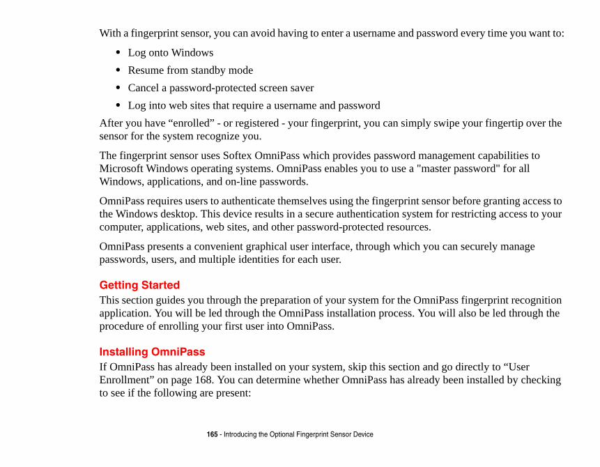
ssword every time you want to:
y swipe your fingertip over the
anagement capabilities to aster password" for all
ensor before granting access to for restricting access to your
.
ou can securely manage
niPass fingerprint recognition u will also be led through the
nd go directly to “User dy been installed by checking
165 - Introducing the Optional Fingerprint Sensor Device
With a fingerprint sensor, you can avoid having to enter a username and pa
• Log onto Windows• Resume from standby mode• Cancel a password-protected screen saver• Log into web sites that require a username and password
After you have “enrolled” - or registered - your fingerprint, you can simplsensor for the system recognize you.
The fingerprint sensor uses Softex OmniPass which provides password mMicrosoft Windows operating systems. OmniPass enables you to use a "mWindows, applications, and on-line passwords.
OmniPass requires users to authenticate themselves using the fingerprint sthe Windows desktop. This device results in a secure authentication systemcomputer, applications, web sites, and other password-protected resources
OmniPass presents a convenient graphical user interface, through which ypasswords, users, and multiple identities for each user.
Getting StartedThis section guides you through the preparation of your system for the Omapplication. You will be led through the OmniPass installation process. Yoprocedure of enrolling your first user into OmniPass.
Installing OmniPassIf OmniPass has already been installed on your system, skip this section aEnrollment” on page 168. You can determine whether OmniPass has alreato see if the following are present:

right of the screen.
specific Operating Systems
page 168. Otherwise
rive. If you are installing from gram (setup.exe) from the
ocation to which you would like ot directory (e.g. C:\).
ystem. Once your system has ely after installation, OmniPass
Windows Control Panel as well
OMNIPASS HAVE DOES NOT HAVE INISTRATOR USER BEFORE
166 - Introducing the Optional Fingerprint Sensor Device
• The gold key-shaped OmniPass icon in the system tray at the bottom • The Softex program group in the Programs group of the Start menu
System Requirements
The OmniPass application requires space on your hard drive; it also requires(OS’s). The minimum requirements are as follows:
• Windows Vista operating system• At least 35 MB available hard disk space
Installing the OmniPass Application
If OmniPass is already installed on your system, go to “User Enrollment” oncontinue with this section on software installation.
To install OmniPass on your system you must:1 Insert the installation media for the OmniPass application into the appropriate d
CD-ROM or DVD-ROM, you must find and launch the OmniPass installation promedia.
2 Follow the directions provided in the OmniPass installation program. Specify a lOmniPass installed. It is recommended that you NOT install OmniPass in the ro
3 Once OmniPass has completed installation you will be prompted to restart you srebooted you will be able to use OmniPass. If you choose not to restart immediatwill not be available for use until the next reboot.
4 The installation program automatically places an icon (Softex OmniPass) in the as a golden key shaped icon in the taskbar.
FOR INSTALLATION, OMNIPASS REQUIRES THAT THE USER INSTALLING
ADMINISTRATIVE PRIVILEGES TO THE SYSTEM. IF YOUR CURRENT USER
ADMINISTRATIVE PRIVILEGES, LOG OUT AND THEN LOG IN WITH AN ADM
PROCEEDING WITH OMNIPASS INSTALLATION.
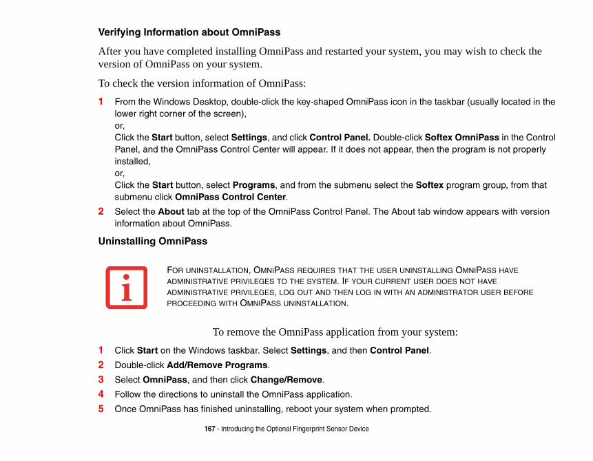
u may wish to check the
taskbar (usually located in the
ftex OmniPass in the Control the program is not properly
ex program group, from that
window appears with version
stem:
LLING OMNIPASS HAVE DOES NOT HAVE INISTRATOR USER BEFORE
167 - Introducing the Optional Fingerprint Sensor Device
Verifying Information about OmniPass
After you have completed installing OmniPass and restarted your system, yoversion of OmniPass on your system.
To check the version information of OmniPass:1 From the Windows Desktop, double-click the key-shaped OmniPass icon in the
lower right corner of the screen), or, Click the Start button, select Settings, and click Control Panel. Double-click SoPanel, and the OmniPass Control Center will appear. If it does not appear, theninstalled, or, Click the Start button, select Programs, and from the submenu select the Softsubmenu click OmniPass Control Center.
2 Select the About tab at the top of the OmniPass Control Panel. The About tab information about OmniPass.
Uninstalling OmniPass
To remove the OmniPass application from your sy1 Click Start on the Windows taskbar. Select Settings, and then Control Panel.
2 Double-click Add/Remove Programs.
3 Select OmniPass, and then click Change/Remove.
4 Follow the directions to uninstall the OmniPass application.
5 Once OmniPass has finished uninstalling, reboot your system when prompted.
FOR UNINSTALLATION, OMNIPASS REQUIRES THAT THE USER UNINSTA
ADMINISTRATIVE PRIVILEGES TO THE SYSTEM. IF YOUR CURRENT USER
ADMINISTRATIVE PRIVILEGES, LOG OUT AND THEN LOG IN WITH AN ADM
PROCEEDING WITH OMNIPASS UNINSTALLATION.

o OmniPass.
logging into your computer, k resources, you often have to entials that you have to
er. This master password
uter) and enrolls an OmniPass is webmail site to log onto his and password “lifebook”), but d. Now whenever he returns to
e OmniPass authentication s many web sites or password his OmniPass user credentials th the system onto which he tials of the password protected ount to access his webmail, he book”) to gain access. If he ’s enrolled on, he will not gain
168 - Introducing the Optional Fingerprint Sensor Device
User EnrollmentBefore you can use any OmniPass features you must first enroll a user intMaster Password Concept
Computer resources are often protected with passwords. Whether you areaccessing your email, e-banking, paying bills online, or accessing networsupply credentials to gain access. This can result in dozens of sets of credremember.
During user enrollment a "master password” is created for the enrolled us“replaces” all other passwords for sites you register with OmniPass.
Example: A user, John, installs OmniPass on his system (his home compuser with username “John_01” and password “freq14”. He then goes to haccount. He inputs his webmail credentials as usual (username “John_02”instead of clicking [Submit], he directs OmniPass to Remember Passworthat site, OmniPass will prompt him to supply access credentials.
John enters his OmniPass user credentials (“John_01” and “freq14”) in thprompt, and he is allowed into his webmail account. He can do this with aprotected resources he likes, and he will gain access to all those sites with(“John_01” and “freq14”). This is assuming he is accessing those sites wienrolled his OmniPass user. OmniPass does not actually change the credenresource. If John were to go to another computer without he OmniPass accwould need to enter his original webmail credentials (“John_02” and “lifeattempts his OmniPass user credentials on a system other than a system heaccess.

user. Unless you specified on Windows login. If you do e Windows taskbar; select
he OmniPass Enrollment Wizard
ter password” for this OmniPass e. In a corporate environment, or s computer name. Click [Next] to
print” on page 170 for additional
you keep Taskbar Tips on tem beeps only until you get nrollment. You will then see a
u’d like to log in to OmniPass with
AUTHENTICATION DEVICES OR ITH OMNIPASS. IF YOU DESIRE IS DOCUMENT.
169 - Introducing the Optional Fingerprint Sensor Device
Basic Enrollment
The Enrollment Wizard will guide you through the process of enrolling a otherwise, after OmniPass installation the Enrollment Wizard will launchnot see the Enrollment Wizard, you can bring it up by clicking Start on thPrograms; select Softex; click OmniPass Enrollment Wizard.
1 Click Enroll to proceed to username and password verification. By default, tenters the credentials of the currently logged in Windows user.
2 Enter the password you use to log in to Windows. This will become the “masuser. In most cases, the Domain: value will be your Windows computer namwhen accessing corporate resources, the Domain: may not be your Windowcontinue.
3 In this step OmniPass captures your fingerprint. Refer to “Enrolling a Fingerinformation.
4 Next, choose how OmniPass notifies you of various events. We recommendBeginner mode taskbar tips and Audio Tips on at least Prompt with sysaccustomed to how OmniPass operates. Click [Next] to proceed with user eCongratulations screen indicating your completion of user enrollment.
5 Click [Done] to exit the OmniPass Enrollment Wizard. You will be asked if yoyour newly enrolled user; click [Yes].
THE ENROLLMENT PROCEDURE ASSUMES YOU HAVE NO HARDWARE
ALTERNATE STORAGE LOCATIONS THAT YOU WISH TO INTEGRATE WSUCH FUNCTIONALITY, CONSULT THE APPROPRIATE SECTIONS OF TH

mline the authentication
ss user logged in, double-click rollment under the User authentication prompt to start
ish to enroll. Fingers that have to enroll at this time will be marked er that has already been enrolled old fingerprint. Select a finger to
a several capture attempts before ngerprint, or if the capture screen
sembles a skinny elongated e sensor (starting at the second capture. The Choose Finger hen you are comfortable with how
print screen will automatically and swipe it as if you were having erprint in the capture window and en suggest you register a second
170 - Introducing the Optional Fingerprint Sensor Device
Enrolling a Fingerprint
Enrolling a fingerprint will increase the security of your system and streaprocedure.
You enroll fingerprints in the OmniPass Control Center. With an OmniPathe system tray OmniPass icon. Select the User Settings tab and click EnSettings area. Click Enroll Authentication Device and authenticate at thedevice enrollment.1 During initial user enrollment, you will be prompted to select the finger you w
already been enrolled will be marked by a green check. The finger you select by a red arrow. OmniPass will allow you re-enroll a finger. If you choose a fingand continue enrollment, OmniPass will enroll the fingerprint, overwriting theenroll and click [Next].
2 It is now time for OmniPass to capture your selected fingerprint. It may take OmniPass acquires your fingerprint. Should OmniPass fail to acquire your fitimes out, click [Back] to restart the fingerprint enrollment process. Your system has a “swipe” fingerprint sensor. A swipe sensor is small and rerectangle. To capture a fingerprint, gently swipe or pull your fingertip over thknuckle) towards yourself. Swiping too fast or too slow will result in a failedscreen has a [Practice] button; click it to practice capturing your fingerprint. Wyour fingerprint is captured, proceed to enroll a finger.
3 Once OmniPass has successfully acquired the fingerprint, the Verify Fingerappear. To verify your enrolled fingerprint, place your fingertip on the sensor a fingerprint captured. Successful fingerprint verification will show a green fingthe text Verification Successful under the capture window. OmniPass will thfingerprint; follow the same steps to do so.

l streamline your
stricted access website (e.g., lways prompted to enter your iPass your login credentials.
print to gain access.
not seen before at Windows enever the OmniPass e invoked frequently: during n, when resuming from
ng password replacement for OmniPass is prompting you
ction you are attempting. The ds are available to you. re not. When you click the
ociated with that method is
s: an enrolled finger for the d prompt (the key icon).
rce that has a password
171 - Introducing the Optional Fingerprint Sensor Device
Using OmniPassYou are now ready to begin using OmniPass. Used regularly, OmniPass wilauthentications.
Password Replacement
You will often use the password replacement function. When you go to a reyour bank, your web-based email, online auction or payment sites), you are alogin credentials. OmniPass can detect these prompts and you can teach OmnThe next time you go to that website, you can authenticate with your finger
OmniPass Authentication Toolbar
After installing OmniPass and restarting, you will notice a dialog you have Logon. This is the OmniPass Authentication Toolbar, and it is displayed whauthentication system is invoked. The OmniPass authentication system may bWindows Logon, during OmniPass Logon, when unlocking your workstatiostandby or hibernate, when unlocking a password-enabled screensaver, duriremembered site or application logins, and more. When you see this toolbar,to authenticate.
The Logon Authentication window indicates what OmniPass-restricted funicons in the lower left (fingerprint and key) show what authentication methoSelected authentication methods are highlighted while unselected methods aicon for an unselected authentication method, the authentication prompt assdisplayed.
When prompted to authenticate, you must supply the appropriate credentialfingerprint capture window or your master password for the master passwor
Remembering a Password
OmniPass can remember any application, GUI, or password protected resouprompt.

ass. These credentials will
yet. At the site login prompt, he site (do not hit [Enter], elect Remember Password
mniPass cursor. Click the it].
ll prompt you to enter a f the website, the company, tes this friendly name with
pportunity to set how r how OmniPass handles a
or this password protected te to this site OmniPass will nce you have authenticated
ite when it is activated. Do each time you navigate to
nticate.
172 - Introducing the Optional Fingerprint Sensor Device
Using the following procedure, you can store a set of credentials into OmniPthen be linked to your “master password” or fingerprint.
Go to a site that requires a login (username and password), but do not log in enter your username and password in the prompted fields, but do not enter t[Submit], [OK], or Login). Right-click the OmniPass system tray icon and sfrom the submenu. The Windows arrow cursor will change to a golden key OOmniPass cursor in the login prompt area, but don’t click [Login] or [Subm
Associating a Friendly Name
After clicking the OmniPass key cursor near the login prompt, OmniPass wi“friendly name” for this site. You should enter something that reminds you oor the service you are logging into. In its secure database, OmniPass associathis website.
Additional Settings for Remembering a Site
When OmniPass prompts you to enter a “friendly name” you also have the oOmniPass authenticates you to this site. There are three effective settings foremembered site.
The default setting is Automatically click the “OK” or “Submit” button fsite once the user is authenticated. With this setting, each time you navigaprompt you for your master password or fingerprint authentication device. Owith OmniPass, you will automatically be logged into the site.
Less secure is the option to Automatically enter this password protected snot prompt for authentication. Check the upper box to get this setting, andthis site OmniPass will log you into the site without prompting you to authe

ill prompt you for your master ed with OmniPass your ck the website [OK], [Submit],
ation, the credentials to access ed in the OmniPass secure
rd Site) can always be changed
remembered site is determined ment.
s, remembered web sites, and
be presented with a master to the site.
A SITE REMEMBERED WITH THIS GAIN INSTANT ACCESS TO THE UR OMNIPASS USER LOGGED IN,
ROTECTED SITES AND GAIN
173 - Introducing the Optional Fingerprint Sensor Device
If you uncheck both boxes in Settings for this Password Site, OmniPass wpassword or fingerprint authentication device. Once you have authenticatcredentials will be filled in to the site login prompt, but you will have to clior [Login] button to gain access to the site.
Click Finish to complete the remember password procedure. The site locthe site, and the OmniPass authentication settings for the site are now stordatabase. The OmniPass authentication settings (Settings for this Passwoin Vault Management.
Logging in to a Remembered Site
Whether or not OmniPass prompts you to authenticate when you return to aby Settings for this Password Site and can be changed in Vault Manage
The following cases are applicable to using OmniPass to login to: Windowall other password protected resources.
With Master Password
Once you return to a site you have remembered with OmniPass, you maypassword prompt. Enter your master password and you will be allowed in
THIS SETTING IS MORE CONVENIENT IN THAT WHENEVER YOU GO TO
SETTING, YOU WILL BYPASS ANY AUTHENTICATION PROCEDURE AND
SITE. BUT SHOULD YOU LEAVE YOUR SYSTEM UNATTENDED WITH YO
ANYONE USING YOUR SYSTEM CAN BROWSE TO YOUR PASSWORD PAUTOMATIC ACCESS.

ure window will now appear sor to authenticate. You will w will also appear if you have to log back in as stated above.
fast user switching and logon ge this go to Control Panel, If your Windows screensaver t to screensaver password rompt with your enrolled
ccess this GUI, double-click e prompted to authenticate. der Vault Settings. You will
hting the desired resource password be reset, or an ht the desired resource under
to confirm the password
R LOGGING BACK IN WITH A ND USER LOGGED IN.
174 - Introducing the Optional Fingerprint Sensor Device
Logging into Windows with a Fingerprint Device
When logging into Windows with a fingerprint device, the fingerprint captnext to the Windows Login screen. Place your enrolled fingertip on the senbe simultaneously logged into Windows and OmniPass. The capture windoused Ctrl-Alt-Del to lock a system, and the fingerprint device can be used
In Windows XP, your login options must be set either for classic login, or forscreen to be enabled to use your fingerprint to log on to Windows. To chanselect User Accounts and then click Change the way users log on or off. is password protected, the fingerprint capture window will now appear nexdialog during resume. You can authenticate to your screensaver password pfinger.
Password Management
OmniPass provides an interface that lets you manage your passwords. To athe OmniPass key in the system tray. Click Vault Management; you will bOnce you gain access to Vault Management, click Manage Passwords unsee the Manage Passwords interface, with a list of friendly names.
You can view the credentials stored for any remembered website by highligunder Password Protected Dialog and clicking Unmask Values. Should aaccount expire, you can remove stored credentials from OmniPass. HighligPassword Protected Dialog and click Delete Page. You will be prompteddeletion.
IF A MACHINE IS LOCKED AND OMNIPASS DETECTS A DIFFERENT USE
FINGERPRINT, THE FIRST USER WILL BE LOGGED OUT AND THE SECO

ompts you to authenticate or
pt to use Remember
f your password is reset in assword change and prompt ew Windows password in the Windows password.
e.g., [email protected] and would be limited to
em tray. Click Vault ccess to Vault Management, ntities of the currently logged
d a new identity. Name the new identity and start
elete Identity], then click
ED SITES AND PASSWORD
175 - Introducing the Optional Fingerprint Sensor Device
The two check boxes in Manage Passwords govern whether OmniPass prdirectly logs you into the remembered site.
OmniPass will overwrite an old set of credentials for a website if you attemPassword on an already remembered site.
The exception to the above rule is when resetting the Windows password. IWindows, the next time you login to Windows, OmniPass will detect the pyou to “Update” or “Reconfirm” the password with OmniPass. Enter your nprompt and click OK. Your OmniPass "master password" will still be your
OmniPass User Identities
Identities allow OmniPass users to have multiple accounts to the same site ([email protected]). If OmniPass did not provide you identities, youremembering one account per site.
To create and manage identities, double-click the OmniPass key in the systManagement; OmniPass will prompt you to authenticate. Once you gain aclick Manage Identities under Vault Settings. You can only manage the idein OmniPass user
To add a new identity, click New Identity or double-click Click here to adnew identity and click [OK], then click [Apply]. You can now switch to theremembering passwords.
To delete an identity, highlight the identity you want to delete and click [D[Apply].
WHEN YOU DELETE AN IDENTITY, ALL OF ITS ASSOCIATED REMEMBER
PROTECTED DIALOGS ARE LOST.

[Set as Default]; click erprint device, you will an choose the identity with
field. Press [Tab] and see ursor to it, and you will see click OK.
click Switch User Identity identity and then click OK.
mniPass Control Center, e which identity you are d protected dialogs that are lained in “Password
niPass Control Center.
SER WITH THE SAME NAME
176 - Introducing the Optional Fingerprint Sensor Device
To set the default identity, highlight the identity you want as default and click[Apply] to ensure the settings are saved. If you log in to OmniPass with a fingautomatically be logged in to the default identity for that OmniPass user. You cwhich you are logging in if you login using "master password".
Choosing User Identity during Login
To choose your identity during login, type your username in the User Name:that the Domain: field self-populates. Click the Password: field to bring the cthe pull-down menu in the Identity: field. Select the identity to login as, then
Switch User Identity
To switch identities at any time, right-click the OmniPass system tray icon and from the submenu. The Switch Identity dialog will appear. Select the desired
Identities and Password Management
On the Manage Passwords interface of the Vault Management tab of the Othere is a pull-down selection box labeled, Identity. This field lets you choosmanaging passwords for. When you select an identity here, only those passworassociated with that identity are shown. You can perform all the functions expManagement” on page 174.
Configuring OmniPassThis section gives an overview of both the Export/Import function and the OmExporting and Importing Users
YOU CANNOT IMPORT A USER INTO OMNIPASS IF THERE ALREADY IS A UENROLLED IN OMNIPASS.

ut of OmniPass. The export nts for an OmniPass user. All During the import process, the annot be supplied, the user
port User under Manage
uthenticate. Upon successfully re to save it. An .opi file is
encrypted and password files.
Import/Export User under mniPass Import/Export File le you had previously exported ompt you for authentication. ws login credentials of the
IN A SAFE PLACE. IF ANYTHING TO A NEW SYSTEM AND HAVE ALL
N YOU EXAMINE THE IMPORTATION, YOU ER PROFILE TO BE IMPORTED ARE THE IALS THAT HAD TO BE SUBMITTED WHEN D DOMAIN.
177 - Introducing the Optional Fingerprint Sensor Device
Using OmniPass Control Center, you can export and import users in and oprocess backs up all remembered sites, credentials, and enrolled fingerpriOmniPass data for a user is backed up to a single encrypted database file. Windows login of the exported user is required. If the proper credentials cprofile will not be imported.
Exporting an OmniPass User Profile
To export a user, open the OmniPass Control Center, and click Import/ExUsers.
Click Exports an OmniPass user profile. OmniPass will prompt you to aauthentication, you must name the OmniPass user profile and decide whegenerated, and you should store a copy of it in a safe place.
This .opi file contains all your user specific OmniPass data, and it is bothprotected. This user profile does NOT contain any of your encrypted data
Importing an OmniPass User Profile
To import an OmniPass user open the OmniPass Control Center, and clickManage Users. Click Imports a new user into OmniPass and then select O(*.opi) and click Next. OmniPass will then prompt you to browse for the fi(.opi file). When you select the .opi file for importation, OmniPass will prThe credentials that will allow a user profile to be imported are the Windo
• YOU SHOULD PERIODICALLY EXPORT YOUR USER PROFILE AND STORE ITHAPPENS TO YOUR SYSTEM, YOU CAN IMPORT YOUR OMNIPASS PROFILE
YOUR REMEMBERED SETTINGS AND FINGERPRINTS INSTANTLY.
• YOU DON'T FORGET THE WINDOWS LOGIN CREDENTIALS WHEN EXPORTING. WHE
ARE PROMPTED FOR AUTHENTICATION. THE CREDENTIALS THAT WILL ALLOW A US
WINDOWS LOGIN CREDENTIALS OF THE EXPORTED USER. THEY ARE THE CREDENT
THE USER PROFILE WAS EXPORTED. YOU WILL NEED USER NAME, PASSWORD, AN

er profile was exported. You lue for Domain, in a PC or
u want to import that profile ile, a Windows user with the
profile.
assword “Sunshine” on my rds. I want to take all my to my new system and using sword "Sunshine". I can now
omputer running OmniPass, ss. er already enrolled in
nter that weren’t explained
skbar (typically in the lower-
rogram group; and click the
178 - Introducing the Optional Fingerprint Sensor Device
exported user. They are the credentials that had to be submitted when the uswill need User Name, Password, and Domain. If you don’t remember the vaSOHO environment Domain should be your computer name.
OmniPass will notify you if the user was successfully imported.
Things to Know Regarding Import/Export
• Assume you export a local Windows User profile from OmniPass. Yoto another machine that has OmniPass. Before you can import the profsame login credentials must be created on the machine importing the Example: I have a Windows user with the username “Tom” and the psystem. I have enrolled Tom into OmniPass and remembered passwopasswords to new system. I export Tom’s OmniPass user profile. I gothe Control Panel I create a user with the username "Tom" and the passuccessfully import the OmniPass user data to the new system.
• If you export an OmniPass-only user, you can import that user to any cprovided that a user with that name is not already enrolled in OmniPa
• If you attempt to import a user profile who has the same name as a usOmniPass, the OmniPass import function will fail.
OmniPass Control CenterThis section will serve to explain functions within the OmniPass Control Ceearlier.
You can access the OmniPass Control Center any of three ways:
• Double-click the golden OmniPass key shaped icon in the Windows taright corner of the desktop)
• Click the Start button; select the Programs group; select the Softex pOmniPass Control Center selection.

tings -> Control Panel) and
d Import/Export User. g Users” on page 176.
rollment Wizard. The
o authenticate. Authenticate . OmniPass will prompt you
d Enrollment. User settings er User Settings (Audio
OmniPass events (e.g., udio Settings and Taskbar
e to enroll and authentication uthentication Device, and Select Authentication ger enrolled) and click Next.
TA ASSOCIATED WITH THAT USER. BE LOST.
OU EXPORT THE USER PROFILE.
179 - Introducing the Optional Fingerprint Sensor Device
• Open the Windows Control Panel (accessible via Start button -> Setdouble-click the Softex OmniPass icon.
User Management
The User Management tab has two major interfaces: Add/Remove User anImport/Export User functionality is documented in “Exporting and ImportinAdd/Remove User functionality is straightforward.
If you click Adds a new user to OmniPass you will start the OmniPass EnEnrollment Wizard is documented in “User Enrollment” on page 168.
If you click Removes a user from OmniPass, OmniPass will prompt you twith the credentials (or enrolled fingerprint) of the user you wish to removeto confirm user removal. Click OK to complete user removal.
User Settings
The User Settings tab has four interfaces: Audio Settings, Taskbar Tips, anallow users to customize OmniPass to suit their individual preferences. UndSettings and Taskbar Tips) you can set how OmniPass notifies the user ofsuccessful login, access denied, etc.). The details of each setting under the ATips interfaces are self-explanatory.
The Enrollment interface allows you to enroll fingerprints. For the procedurdevice refer to Chapter 2.3. To enroll additional fingerprints, click Enroll Aauthenticate with OmniPass. Select the fingerprint recognition device in theDevice screen (it should already be marked by a green check if you have a fin
REMOVING A USER WILL AUTOMATICALLY DESTROY ALL OMNIPASS DA
ALL IDENTITIES AND CREDENTIALS ASSOCIATED WITH THE USER WILL
IF YOU’RE SURE YOU WANT TO REMOVE THE USER, WE RECOMMEND Y

ngs tab. With these options you
, will do just as it says; during login credentials. If the user ne will be logged on to here users must enter a
iPass will prompt you to login
will not prompt for a user to be
kbar icon and clicking Log in
he Windows user, and you will d, you can add that user to
may need to adjust your local ministrative Tools, and Local nd double-click Network t setting should be Classic -
180 - Introducing the Optional Fingerprint Sensor Device
System Settings
The OmniPass Startup Options interface can be found in the System Settican specify how your OmniPass Logon is tied to your Windows Logon.
The first option, Automatically log on to OmniPass as the current userWindows login, you will be logged on to OmniPass using your Windows logging into Windows was never enrolled into OmniPass, upon login no oOmniPass. This setting is appropriate for an office setting or any setting wusername and password to log into a computer. This is the default setting.
With the second option, Manually log on to OmniPass at startup, Omnonce you have logged on to Windows.
With the third option, Do not log on to OmniPass at startup, OmniPass logged on.
You can manually log on to OmniPass by right-clicking the OmniPass tasUser from the right-click menu.
TroubleshootingYou cannot use OmniPass to create Windows users. You must first create tneed administrative privileges to do that. Once the Windows user is createOmniPass using the same username and password
Cannot add Windows users to OmniPass
If you experience difficulties adding a Windows user to OmniPass, yousecurity settings. You can do this by going to Start, Control Panel, AdSecurity Settings. Expand Local Policies, expand Security Options, aAccess: Sharing and Security Model for Local Accounts. The correcLocal Users Authenticate as Themselves.

niPass, you may need to adjust e Cannot add Windows user to edure.
y Settings. Expand Local local account use of blank d.
on
indows using OmniPass. You ity device) and OmniPass logs a Login Error dialog box.
dows with the credentials llowing reasons:
date OmniPass with your will be prompted with a dialog
f the error persists, then it is anging.
181 - Introducing the Optional Fingerprint Sensor Device
Cannot add a User with a Blank Password to OmniPass
If you experience difficulties adding a user with a blank password to Omyour local security settings. First attempt the procedure explained in thOmniPass section. If the difficulties persist, then try the following proc
Click Start, Control Panel, Administrative Tools, and Local SecuritPolicies, expand Security Options, and double-click Accounts: Limitpasswords to console login only. This setting should be set to Disable
Dialog appears after OmniPass authentication during Windows Log
After installing OmniPass on your system, you can choose to logon to Wauthenticate with OmniPass (via master password, or an enrolled securyou into Windows. You may, during this OmniPass authentication, see
This dialog box occurs when OmniPass was unable to log you into Winsupplied (username and password). This could happen for any of the fo
• Your Windows password has changed• Your Windows account has been disabled
If you are having difficulties due to the first reason, you will need to upchanged Windows account password. Click Update Password and you to reconfirm your password.
Enter the new password to your Windows user account and click OK. Iunlikely the problem is due to your Windows user account password ch

Information 162
17Guide 13
182
Index
AAbout This Guide 1, 13AC
adapter 43plug adapters 114
Anti-theft lock slot 21, 23Application Panel 38Auto/Airline Adapter 43Automatically Downloading Driver Updates 108
BBattery 56
alarm 58bay 26care 115cold-swapping 59conserving power 52dead 93faulty 94increasing life 115level indicator 28lithium ion battery 56low 58problems 93, 94recharging 57replacing 59shorted 58Standby mode 58
BIOSguide 49setup utility 48
Bluetooth, Where to FindBuilt-in Speakers 88
CCapsLock 29CD-ROM 88, 89Click Me! 51Clicking 34Cold-swapping 59Configuration Label 119Controls and ConnectorsConventions Used in the Cursor 33Cursor Keys 31
DDC Output Cable 43DC Power Jack 43Device Ports 79, 122DIMM 75Disk care 116Display Panel 18, 44
adjusting 45brightness 45closing 45

29
183
latch 18opening 44problems 95, 96
Double-Clicking 34Dragging 36Drivers and Application Restore CD 104DVD drive
problems 88, 89tray release 64
EEmergency tray release 21, 23Error Messages 98ExpressCards 68External Floppy Disk Drive, problems 89External Monitor Port 21, 82
FFDU 51, 108, 126Fingerprint Sensor Device 164
enrolling a fingerprint 170getting started 165installing OmniPass 165logging into a remembered site 173OmniPass authentication toolbar 171password replacement 171remembering a password 171uninstalling OmniPass 167user enrollment 168using OmniPass 171
Flexible Bay 20eject lever 20Modular Multi-Format DVD Writer 61
Fujitsu Contact Information 14Fujitsu Driver Update utility 51, 108, 126
Fujitsu Support Center 40Function Key
F10 32F3 32F6 32F7 32F8 32, 37F9 32, 37FN 32
HHard Disk Drive
access indicator 27, problems 90
Headphone Jack 81Hibernation Feature 54
disable/enable 54
IInstalling 69, 70Internal LAN Jack 80
KKeyboard 18, 30
cursor keys 31function keys 31numeric keypad 31problems 90windows keys 31

Jack 19
2
tton 18, 52
125
d Software 104
184
LLAN (RJ-45) Jack 21, 23LifeBook Application Panel
configuring 41deactivating and activating 41launching applications 41
LifeBook Security Application Panel 19buttons 38configuring 39launching applications 38
MMedia Player
care 117Control Panel 65loading 62removing 64Software 62, 65using 66
Memorycapacity 77compartment 26, 76installing 75problems 91removing 77upgrade module 75
Memory Stickinstalling 74removing 74
Memory Stick/SD Card Slot 22Microphone Jack 19, 82Modem 25, 91Modem Jack 79Modem Result Codes 103Mouse problems 90
NNumLk 29
OOptical Digital Audio-Out Optical Drive 61
PPC Card
problems 91, 92removing 69, 71slot 21, 22
PowerAC adapter 42Auto/Airline adapter 4failure 92, 93management 52off 55on 46problems 94sources 42
Power Management 52Power On Self Test 46, 98Power/Suspend/Resume BuPre-Installed Software 124
Adobe Acrobat ReaderGoogle Toolbar 126manuals 125
RRegistration 51Restarting 54Restoring Your Pre-installeRJ-11 79RJ-45 80

105
ireless LAN 152
8
185
SScrLk 29SD Card
installing 74removing 74
SDRAM 26, 75Security Panel 38Sleep Mode 52Specifications 119
Audio 121Chipset 120Dimensions and Weight 123Environmental Requirements 124Keyboard 123Memory 120Microprocessor 120Power 123Video 120
Status Indicator Panel 18, 27Stereo Speakers 19Support Button 40
TTouchpad 33
buttons 33controls 36
Touchpad Pointing Device 19Troubleshooting 85
UUniversal Serial Bus Ports 81Unpacking 16USB 81, 91USB 2.0 Ports 20, 21, 23
VVolume control 37
WWarranty 15Windows keys 31
Application key 31Start keys 31
Windows Vista, restoringWireless LAN
Before Using the WSpecifications 160Troubleshooting 15