Embed Size (px)
Citation preview
User’s Guide
Learn how to use your Fujitsu LifeBook P1630 notebook

ation
f this document; however, as ongoing accuracy of the contents of this
oration or its subsidiaries in
icrosoft Corporation in the
s Incorporated in the United States
in the United States and other
Copyright and Trademark Inform
Fujitsu Computer Systems Corporation has made every effort to ensure the accuracy and completeness odevelopment efforts are continually improving the capabilities of our products, we cannot guarantee thedocument. We disclaim liability for errors, omissions, or future changes.
Fujitsu, the Fujitsu logo, and LifeBook are registered trademarks of Fujitsu Limited.
Intel, Intel Core, Centrino, and Intel Centrino Pro are trademarks or registered trademarks of Intel Corpthe United States and other countries.
Microsoft, Windows, Windows Vista, and OneNote are either registered trademarks or trademarks of MUnited States and/or other countries.
PCMCIA is a trademark of the Personal Computer Memory Card International Association.
EverNote is a registered trademark of EverNote Corporation.
Bluetooth is a trademark of Bluetooth SIG, Inc., USA.
Google and Picasa are trademarks or registered trademarks of Google Incorporated.
OmniPass is a trademark of Softex, Inc.
Adobe, Acrobat, and Acrobat Reader are either a registered trademarks or trademarks of Adobe Systemand/or other countries.
Norton and Norton Internet Security are trademarks or registered trademarks of Symantec Corporation countries.
All other trademarks mentioned herein are the property of their respective owners.

ent of Fujitsu. No part of this publication B5FJ-9931-01ENZ0-00
, A CHEMICAL KNOWN TO THE DUCTIVE HARM.
oration
2
ok
C Rules.
o the following two conditions: cept any interference received,
© Copyright 2008 Fujitsu Computer Systems Corporation. All rights reserved.
No part of this publication may be copied, reproduced, or translated, without prior written consmay be stored or transmitted in any electronic form without the written consent of Fujitsu.
WARNING
HANDLING THE CORD ON THIS PRODUCT WILL EXPOSE YOU TO LEAD
STATE OF CALIFORNIA TO CAUSE BIRTH DEFECTS OR OTHER REPRO
WASH HANDS AFTER HANDLING.
DECLARATION OF CONFORMITY
according to FCC Part 15
Responsible Party Name: Fujitsu Computer Systems Corp
Address: 1250 E. Arques Avenue, M/S 12Sunnyvale, CA 94085
Telephone: (408) 746-6000
Declares that product: Base Model Configuration:LifeBook P1630 notebo
Complies with Part 15 of the FC
This device complies with Part 15 of the FCC rules. Operations are subject t(1) This device may not cause harmful interference, (2) This device must acincluding interference that may cause undesired operation.
utput rating of 16 VDC, with a
e the risk of fire, electric shock and injury
hen used for long periods of time. When xposed skin, such as the lap. laundry tub, in a wet basement or near a
hock from lightning.
in a fire. They may explode. Check with
lecommunication Line Cord.ystem, make sure that the outer shield of oint of cable entrance as practicable, as
r CATV installation, contact your service
TLY REPLACED. REPLACE ONLY UFACTURER. DISPOSE OF USED
Y WITH THE SAME TYPE AND
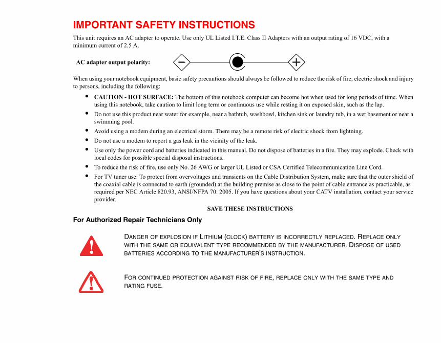
IMPORTANT SAFETY INSTRUCTIONS This unit requires an AC adapter to operate. Use only UL Listed I.T.E. Class II Adapters with an ominimum current of 2.5 A.
When using your notebook equipment, basic safety precautions should always be followed to reducto persons, including the following:
• CAUTION - HOT SURFACE: The bottom of this notebook computer can become hot wusing this notebook, take caution to limit long term or continuous use while resting it on e
• Do not use this product near water for example, near a bathtub, washbowl, kitchen sink orswimming pool.
• Avoid using a modem during an electrical storm. There may be a remote risk of electric s• Do not use a modem to report a gas leak in the vicinity of the leak.• Use only the power cord and batteries indicated in this manual. Do not dispose of batteries
local codes for possible special disposal instructions.• To reduce the risk of fire, use only No. 26 AWG or larger UL Listed or CSA Certified Te• For TV tuner use: To protect from overvoltages and transients on the Cable Distribution S
the coaxial cable is connected to earth (grounded) at the building premise as close to the prequired per NEC Article 820.93, ANSI/NFPA 70: 2005. If you have questions about youprovider.
SAVE THESE INSTRUCTIONS
For Authorized Repair Technicians Only
DANGER OF EXPLOSION IF LITHIUM (CLOCK) BATTERY IS INCORREC
WITH THE SAME OR EQUIVALENT TYPE RECOMMENDED BY THE MAN
BATTERIES ACCORDING TO THE MANUFACTURER’S INSTRUCTION.
FOR CONTINUED PROTECTION AGAINST RISK OF FIRE, REPLACE ONL
RATING FUSE.
+AC adapter output polarity:

ount of time; this is a natural occurrence lace it, it is important that you dispose of
e if disposed of improperly.
rvices of the Rechargeable Battery cated to protecting our environment by
d States and Canada. To find the location
ion Initiative website (http://EIAE.org/)
to protect it for current and future
t www.shopfujitsu.com in the US or
ng; RBRC is in no way affiliated with
Recycling your battery
Over time, the batteries that run your mobile computer will begin to hold a charge for a shorter amfor all batteries. When this occurs, you may want to replace the battery with a fresh one*. If you repthe old battery properly because batteries contain materials that could cause environmental damag
Fujitsu is very concerned with environmental protection, and has enlisted the seRecycling Corporation (RBRC)**, a non-profit public service organization dedirecycling old batteries at no cost to you.
RBRC has drop-off points at tens of thousands of locations throughout the Unitenearest you, go to www.RBRC.org or call 1-800-822-8837.
If there are no convenient RBRC locations near you, you can also go to the EIA Consumer Educatand search for a convenient disposal location.
Remember – protecting the environment is a cooperative effort, and you should make every effort generations.
* To order a new battery for your Fujitsu mobile computer, go to the Fujitsu shopping site awww.fujitsu.ca/products/notebooks in Canada.
** RBRC is an independent third party to which Fujitsu provides funding for battery recycliFujitsu.

Prefac
Chap
Contents
e
About This Guide . . . . . . . . . . . . . . . . . . . . . . . . . . . . . . . . . . . . . . . . . . . . . 13Conventions Used in the Guide . . . . . . . . . . . . . . . . . . . . . . . . . . . . . . . . . 13Fujitsu Contact Information . . . . . . . . . . . . . . . . . . . . . . . . . . . . . . . . . . . . 14
ter 1 Getting to Know Your LifeBook
Overview . . . . . . . . . . . . . . . . . . . . . . . . . . . . . . . . . . . . . . . . . . . . . . . . . . . . 16
Locating the Controls and Connectors . . . . . . . . . . . . . . . . . . . . . . . . . . . . 17Front and Display Components . . . . . . . . . . . . . . . . . . . . . . . . . . . . . . . . . 20Left-Side Panel Components . . . . . . . . . . . . . . . . . . . . . . . . . . . . . . . . . . . 22Right-Side Panel Components . . . . . . . . . . . . . . . . . . . . . . . . . . . . . . . . . . 23Back Panel Components. . . . . . . . . . . . . . . . . . . . . . . . . . . . . . . . . . . . . . . 25Bottom Components. . . . . . . . . . . . . . . . . . . . . . . . . . . . . . . . . . . . . . . . . . 27
Status Indicator Panel . . . . . . . . . . . . . . . . . . . . . . . . . . . . . . . . . . . . . . . . . 29Power Indicator . . . . . . . . . . . . . . . . . . . . . . . . . . . . . . . . . . . . . . . . . . . . . 30Battery Level Indicator. . . . . . . . . . . . . . . . . . . . . . . . . . . . . . . . . . . . . . . . 30Hard Drive Access Indicator . . . . . . . . . . . . . . . . . . . . . . . . . . . . . . . . . . . 31NumLk Indicator . . . . . . . . . . . . . . . . . . . . . . . . . . . . . . . . . . . . . . . . . . . . 31CapsLock Indicator . . . . . . . . . . . . . . . . . . . . . . . . . . . . . . . . . . . . . . . . . . 31ScrLk Indicator . . . . . . . . . . . . . . . . . . . . . . . . . . . . . . . . . . . . . . . . . . . . . . 31
. 32 . 32 . 33 . 34 . 35
. 37 . 37
. 40 . 42 . 44 . 45 . 45 . 45
. 47 . 47
. 48 . 49 . 49 . 51 . 52 . 53 . 54 . 57
7
Display Panel . . . . . . . . . . . . . . . . . . . . . . . . . . . . . . . . . . . . . . . . . . . . . . . .Opening the Display Panel . . . . . . . . . . . . . . . . . . . . . . . . . . . . . . . . . . . .Using the System as a Tablet . . . . . . . . . . . . . . . . . . . . . . . . . . . . . . . . . .Display Orientations in Tablet Configuration . . . . . . . . . . . . . . . . . . . . .Adjusting Display Panel Brightness . . . . . . . . . . . . . . . . . . . . . . . . . . . . .
Keyboard . . . . . . . . . . . . . . . . . . . . . . . . . . . . . . . . . . . . . . . . . . . . . . . . . . .Using the Keyboard . . . . . . . . . . . . . . . . . . . . . . . . . . . . . . . . . . . . . . . . .
Quick Point Pointing Device/Touch Screen . . . . . . . . . . . . . . . . . . . . . . . Quick Point Control Adjustment . . . . . . . . . . . . . . . . . . . . . . . . . . . . . . .Clicking. . . . . . . . . . . . . . . . . . . . . . . . . . . . . . . . . . . . . . . . . . . . . . . . . . .Calibrating the Touch Screen . . . . . . . . . . . . . . . . . . . . . . . . . . . . . . . . . .Double-Clicking . . . . . . . . . . . . . . . . . . . . . . . . . . . . . . . . . . . . . . . . . . . .Dragging . . . . . . . . . . . . . . . . . . . . . . . . . . . . . . . . . . . . . . . . . . . . . . . . . .
Volume Control . . . . . . . . . . . . . . . . . . . . . . . . . . . . . . . . . . . . . . . . . . . . . .Controlling the Volume . . . . . . . . . . . . . . . . . . . . . . . . . . . . . . . . . . . . . .
LifeBook Security/Application Panel . . . . . . . . . . . . . . . . . . . . . . . . . . . .Setting up Your LifeBook Security Panel . . . . . . . . . . . . . . . . . . . . . . . .Passwords . . . . . . . . . . . . . . . . . . . . . . . . . . . . . . . . . . . . . . . . . . . . . . . . .Operating Your LifeBook Security/Application Panel. . . . . . . . . . . . . . .Precautions . . . . . . . . . . . . . . . . . . . . . . . . . . . . . . . . . . . . . . . . . . . . . . . .Uninstalling the Security Panel Application. . . . . . . . . . . . . . . . . . . . . . .Launching Applications with the Security/Application Panel . . . . . . . . .Changing Button Functions . . . . . . . . . . . . . . . . . . . . . . . . . . . . . . . . . . .
6060
6161626263646566676768
6969707171727273
757677
8
Chapter 2 Getting Started with Your LifeBook
Power Sources . . . . . . . . . . . . . . . . . . . . . . . . . . . . . . . . . . . . . . . . . . . . . . . . Connecting the Power Adapters . . . . . . . . . . . . . . . . . . . . . . . . . . . . . . . . .
Starting Your LifeBook Notebook. . . . . . . . . . . . . . . . . . . . . . . . . . . . . . . . Power On . . . . . . . . . . . . . . . . . . . . . . . . . . . . . . . . . . . . . . . . . . . . . . . . . . Boot Sequence . . . . . . . . . . . . . . . . . . . . . . . . . . . . . . . . . . . . . . . . . . . . . . Hard Disk Drive Passwords . . . . . . . . . . . . . . . . . . . . . . . . . . . . . . . . . . . . BIOS Setup Utility . . . . . . . . . . . . . . . . . . . . . . . . . . . . . . . . . . . . . . . . . . . Booting the System. . . . . . . . . . . . . . . . . . . . . . . . . . . . . . . . . . . . . . . . . . . Starting Windows Vista the first time . . . . . . . . . . . . . . . . . . . . . . . . . . . . Starting Windows XP the First Time . . . . . . . . . . . . . . . . . . . . . . . . . . . . . Registering Your LifeBook notebook with Fujitsu . . . . . . . . . . . . . . . . . . Installing ClickMe! . . . . . . . . . . . . . . . . . . . . . . . . . . . . . . . . . . . . . . . . . . . Fujitsu Driver Update Utility . . . . . . . . . . . . . . . . . . . . . . . . . . . . . . . . . . .
Power Management. . . . . . . . . . . . . . . . . . . . . . . . . . . . . . . . . . . . . . . . . . . . Power/Suspend/Resume Button . . . . . . . . . . . . . . . . . . . . . . . . . . . . . . . . . Sleep (Standby) Mode . . . . . . . . . . . . . . . . . . . . . . . . . . . . . . . . . . . . . . . . Hibernation (Save-to-Disk) Feature . . . . . . . . . . . . . . . . . . . . . . . . . . . . . . Windows Power Management . . . . . . . . . . . . . . . . . . . . . . . . . . . . . . . . . . Restarting the System . . . . . . . . . . . . . . . . . . . . . . . . . . . . . . . . . . . . . . . . . Powering Off . . . . . . . . . . . . . . . . . . . . . . . . . . . . . . . . . . . . . . . . . . . . . . . ENERGY STAR® Compliance . . . . . . . . . . . . . . . . . . . . . . . . . . . . . . . . .
Chapter 3 User-Installable Features
Lithium ion Battery. . . . . . . . . . . . . . . . . . . . . . . . . . . . . . . . . . . . . . . . . . . . Recharging the Batteries. . . . . . . . . . . . . . . . . . . . . . . . . . . . . . . . . . . . . . . Replacing the Battery . . . . . . . . . . . . . . . . . . . . . . . . . . . . . . . . . . . . . . . . .
9
Memory Upgrade Module . . . . . . . . . . . . . . . . . . . . . . . . . . . . . . . . . . . . . . 80Removing Memory Modules . . . . . . . . . . . . . . . . . . . . . . . . . . . . . . . . . . . 80Installing a Memory Upgrade Module . . . . . . . . . . . . . . . . . . . . . . . . . . . . 82Checking the Memory Capacity . . . . . . . . . . . . . . . . . . . . . . . . . . . . . . . . . 82
Secure Digital Cards . . . . . . . . . . . . . . . . . . . . . . . . . . . . . . . . . . . . . . . . . . . 84Inserting SD Cards . . . . . . . . . . . . . . . . . . . . . . . . . . . . . . . . . . . . . . . . . . . 85Removing An SD Card. . . . . . . . . . . . . . . . . . . . . . . . . . . . . . . . . . . . . . . . 85
PC Cards . . . . . . . . . . . . . . . . . . . . . . . . . . . . . . . . . . . . . . . . . . . . . . . . . . . . 86Installing PC Cards . . . . . . . . . . . . . . . . . . . . . . . . . . . . . . . . . . . . . . . . . . . 86Removing PC Cards . . . . . . . . . . . . . . . . . . . . . . . . . . . . . . . . . . . . . . . . . . 87Smart Card Reader . . . . . . . . . . . . . . . . . . . . . . . . . . . . . . . . . . . . . . . . . . . 88
Port Replicator . . . . . . . . . . . . . . . . . . . . . . . . . . . . . . . . . . . . . . . . . . . . . . . 89Port Replicator Components. . . . . . . . . . . . . . . . . . . . . . . . . . . . . . . . . . . . 89Attaching Port Replicator . . . . . . . . . . . . . . . . . . . . . . . . . . . . . . . . . . . . . . 91Detaching Port Replicator. . . . . . . . . . . . . . . . . . . . . . . . . . . . . . . . . . . . . . 91
Device Ports . . . . . . . . . . . . . . . . . . . . . . . . . . . . . . . . . . . . . . . . . . . . . . . . . . 92Modem (RJ-11) Jack. . . . . . . . . . . . . . . . . . . . . . . . . . . . . . . . . . . . . . . . . . 92Internal LAN (RJ-45) jack . . . . . . . . . . . . . . . . . . . . . . . . . . . . . . . . . . . . . 93Docking Port . . . . . . . . . . . . . . . . . . . . . . . . . . . . . . . . . . . . . . . . . . . . . . . . 93Universal Serial Bus Ports . . . . . . . . . . . . . . . . . . . . . . . . . . . . . . . . . . . . . 93Microphone Jack. . . . . . . . . . . . . . . . . . . . . . . . . . . . . . . . . . . . . . . . . . . . . 94Headphone Jack . . . . . . . . . . . . . . . . . . . . . . . . . . . . . . . . . . . . . . . . . . . . . 94External Video Port . . . . . . . . . . . . . . . . . . . . . . . . . . . . . . . . . . . . . . . . . . 94
66808
13131516
171920212223
24242525252526262627
10
Chapter 4 Troubleshooting Your LifeBook
Troubleshooting. . . . . . . . . . . . . . . . . . . . . . . . . . . . . . . . . . . . . . . . . . . . . . . 9Identifying the Problem . . . . . . . . . . . . . . . . . . . . . . . . . . . . . . . . . . . . . . . 9Specific Problems . . . . . . . . . . . . . . . . . . . . . . . . . . . . . . . . . . . . . . . . . . . . 9Power On Self Test Messages . . . . . . . . . . . . . . . . . . . . . . . . . . . . . . . . . . 1
Restoring Your Pre-installed Software . . . . . . . . . . . . . . . . . . . . . . . . . . . . 1Drivers and Applications Restore Disc. . . . . . . . . . . . . . . . . . . . . . . . . . . . 1Recovering Factory and System Images. . . . . . . . . . . . . . . . . . . . . . . . . . . 1Automatically Downloading Driver Updates . . . . . . . . . . . . . . . . . . . . . . . 1
Chapter 5 Care and Maintenance
Caring for your LifeBook Notebook . . . . . . . . . . . . . . . . . . . . . . . . . . . . . . 1Cleaning your LifeBook notebook . . . . . . . . . . . . . . . . . . . . . . . . . . . . . . . 1Storing your LifeBook notebook . . . . . . . . . . . . . . . . . . . . . . . . . . . . . . . . 1Traveling with your LifeBook notebook . . . . . . . . . . . . . . . . . . . . . . . . . . 1Batteries . . . . . . . . . . . . . . . . . . . . . . . . . . . . . . . . . . . . . . . . . . . . . . . . . . . 1Media Care . . . . . . . . . . . . . . . . . . . . . . . . . . . . . . . . . . . . . . . . . . . . . . . . . 1
Chapter 6 System Specifications
Specifications . . . . . . . . . . . . . . . . . . . . . . . . . . . . . . . . . . . . . . . . . . . . . . . . . 1Configuration Label . . . . . . . . . . . . . . . . . . . . . . . . . . . . . . . . . . . . . . . . . . 1Microprocessor . . . . . . . . . . . . . . . . . . . . . . . . . . . . . . . . . . . . . . . . . . . . . . 1Chipset . . . . . . . . . . . . . . . . . . . . . . . . . . . . . . . . . . . . . . . . . . . . . . . . . . . . 1Memory. . . . . . . . . . . . . . . . . . . . . . . . . . . . . . . . . . . . . . . . . . . . . . . . . . . . 1Video. . . . . . . . . . . . . . . . . . . . . . . . . . . . . . . . . . . . . . . . . . . . . . . . . . . . . . 1Audio . . . . . . . . . . . . . . . . . . . . . . . . . . . . . . . . . . . . . . . . . . . . . . . . . . . . . 1Mass Storage Device Options. . . . . . . . . . . . . . . . . . . . . . . . . . . . . . . . . . . 1Features. . . . . . . . . . . . . . . . . . . . . . . . . . . . . . . . . . . . . . . . . . . . . . . . . . . . 1Device Ports . . . . . . . . . . . . . . . . . . . . . . . . . . . . . . . . . . . . . . . . . . . . . . . . 1
28282929293030
33
49
5757575860616161
62626363
11
Keyboard. . . . . . . . . . . . . . . . . . . . . . . . . . . . . . . . . . . . . . . . . . . . . . . . . . . 1Power . . . . . . . . . . . . . . . . . . . . . . . . . . . . . . . . . . . . . . . . . . . . . . . . . . . . . 1Dimensions and Weight . . . . . . . . . . . . . . . . . . . . . . . . . . . . . . . . . . . . . . . 1Environmental Requirements . . . . . . . . . . . . . . . . . . . . . . . . . . . . . . . . . . . 1Popular Accessories . . . . . . . . . . . . . . . . . . . . . . . . . . . . . . . . . . . . . . . . . . 1Included Software . . . . . . . . . . . . . . . . . . . . . . . . . . . . . . . . . . . . . . . . . . . . 1Learning About Your Software . . . . . . . . . . . . . . . . . . . . . . . . . . . . . . . . . 1
Glossary/Regulatory
Glossary . . . . . . . . . . . . . . . . . . . . . . . . . . . . . . . . . . . . . . . . . . . . . . . . . . . . . 1
Regulatory Information . . . . . . . . . . . . . . . . . . . . . . . . . . . . . . . . . . . . . . . . 1
Appendix A: WLAN User’s Guide
Before Using the Optional Wireless LAN . . . . . . . . . . . . . . . . . . . . . . . . . . 1Wireless LAN Device Covered by this Document. . . . . . . . . . . . . . . . . . . 1Characteristics of the WLAN Device . . . . . . . . . . . . . . . . . . . . . . . . . . . . . 1Wireless LAN Modes Using this Device . . . . . . . . . . . . . . . . . . . . . . . . . . 1Deactivating/Disconnecting the WLAN Device . . . . . . . . . . . . . . . . . . . . 1Deactivation Using the Wireless On/Off Switch . . . . . . . . . . . . . . . . . . . . 1Disconnection Using the Icon in the Taskbar. . . . . . . . . . . . . . . . . . . . . . . 1Activating the WLAN Device . . . . . . . . . . . . . . . . . . . . . . . . . . . . . . . . . . 1
Configuring the Wireless LAN. . . . . . . . . . . . . . . . . . . . . . . . . . . . . . . . . . . 1Configuring the WLAN Using Windows Vista . . . . . . . . . . . . . . . . . . . . . 1Configuring the WLAN Using Windows XP . . . . . . . . . . . . . . . . . . . . . . 1Connection to the network . . . . . . . . . . . . . . . . . . . . . . . . . . . . . . . . . . . . . 1
164164
166166
168168168
170171171174177182184187
189
12
Troubleshooting the WLAN. . . . . . . . . . . . . . . . . . . . . . . . . . . . . . . . . . . . . Troubleshooting . . . . . . . . . . . . . . . . . . . . . . . . . . . . . . . . . . . . . . . . . . . . .
WLAN Specifications . . . . . . . . . . . . . . . . . . . . . . . . . . . . . . . . . . . . . . . . . . Specifications . . . . . . . . . . . . . . . . . . . . . . . . . . . . . . . . . . . . . . . . . . . . . . .
Using the Bluetooth Device. . . . . . . . . . . . . . . . . . . . . . . . . . . . . . . . . . . . . . What is Bluetooth . . . . . . . . . . . . . . . . . . . . . . . . . . . . . . . . . . . . . . . . . . . . Where to Find Information About Bluetooth . . . . . . . . . . . . . . . . . . . . . . .
Appendix B: Fingerprint Sensor Device
Introducing the Fingerprint Sensor Device . . . . . . . . . . . . . . . . . . . . . . . . Getting Started . . . . . . . . . . . . . . . . . . . . . . . . . . . . . . . . . . . . . . . . . . . . . . Installing OmniPass . . . . . . . . . . . . . . . . . . . . . . . . . . . . . . . . . . . . . . . . . . User Enrollment . . . . . . . . . . . . . . . . . . . . . . . . . . . . . . . . . . . . . . . . . . . . . Using OmniPass . . . . . . . . . . . . . . . . . . . . . . . . . . . . . . . . . . . . . . . . . . . . . Configuring OmniPass . . . . . . . . . . . . . . . . . . . . . . . . . . . . . . . . . . . . . . . . OmniPass Control Center . . . . . . . . . . . . . . . . . . . . . . . . . . . . . . . . . . . . . . Troubleshooting . . . . . . . . . . . . . . . . . . . . . . . . . . . . . . . . . . . . . . . . . . . . .
Index . . . . . . . . . . . . . . . . . . . . . . . . . . . . . . . . . . . . . . . . . . . . . . . . . . . . . . . .
Abouporation is a small yet powerful ng keyboard or pen input, or as cessor and integrated Intel® ok has a built-in 8.9” TFT wide
’s hardware and built-in system Tablet PC Edition 2005, -installed.
, [ESC], [ENTER] and [CTRL].
renced within the text. ross-references are linked to the the referenced item or page.
, and select your choice”.
13
Preface
t This GuideThe LifeBook® P1630 notebook from Fujitsu Computer Systems Corconvertible computer. It can be used either as a standard notebook usia tablet using pen input. It is powered by an Intel® Core 2™ Duo proGraphics Media Accelerator GMA X4500 video graphics. The noteboXGA color display.
This manual explains how to operate your LifeBook P1630 notebooksoftware. Your LifeBook P1630 notebook comes with Windows® XPWindows XP Professional Edition, or Windows Vista™ Business pre
Conventions Used in the GuideKeyboard and on-screen keys appear in brackets. Example: [Fn], [F1]
Pages with additional information about a specific topic are cross-refeFor example: (“See Installation Procedure on page 43”.) Note that all creferenced items, so by clicking the link, you will automatically go to
On-screen menu items appear in bold. Example: “Click Fujitsu Menu
ady so that the customer :
CE YOUR UNDERSTANDING OF
THE SAFE OPERATION OF YOUR CAUTION INFORMATION
US TO EITHER YOU, YOUR NFORMATION CAREFULLY.
14 - About This Guide
Fujitsu Contact Information
Service and Support
You can contact Fujitsu Service and Support in the following ways:
• Toll free: 1-800-8Fujitsu (1-800-838-5487)• E-mail: [email protected] • Website: http://www.computers.us.fujitsu.com/supportBefore you place the call, you should have the following information resupport representative can provide you with the fastest possible solution
• Product name• Product configuration number• Product serial number
THE INFORMATION ICON HIGHLIGHTS INFORMATION THAT WILL ENHAN
THE SUBJECT MATERIAL.
THE CAUTION ICON HIGHLIGHTS INFORMATION THAT IS IMPORTANT TO
COMPUTER, OR TO THE INTEGRITY OF YOUR FILES. PLEASE READ ALL
CAREFULLY.
THE WARNING ICON HIGHLIGHTS INFORMATION THAT CAN BE HAZARDO
LIFEBOOK NOTEBOOK, OR YOUR FILES. PLEASE READ ALL WARNING I
pfujitsu.com.
imited Warranty. Check the riod and terms and conditions.
LINE URL LINKS.
15 - About This Guide
• Purchase date• Conditions under which the problem occurred• Any error messages that have occurred• Type of device connected, if any
Fujitsu Shopping Online
You can go directly to the online by going to the website at: www.sho
Limited Warranty
Your LifeBook P1630 notebook is backed by a Fujitsu International Lservice kit that came with your notebook for the Limited Warranty pe
YOU MUST HAVE AN ACTIVE INTERNET CONNECTION TO USE THE ON
Over
1630 notebook
16
Chapter 1
Getting to Know Your LifeBook
view
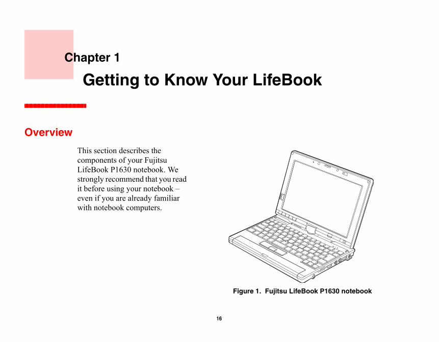
This section describes the components of your Fujitsu LifeBook P1630 notebook. We strongly recommend that you read it before using your notebook – even if you are already familiar with notebook computers.
Figure 1. Fujitsu LifeBook P
d the optional port replicator d in Figures 2 through 6. The 30 notebook and/or optional book or port replicator chassis.
s the AC adapter or auto/airline
ou to install a flash memory card w you to transfer data to and from
ompliant devices to the
system using your fingerprint as
ernal microphone is disabled . The same icon is used for the
17 - Locating the Controls and Connectors
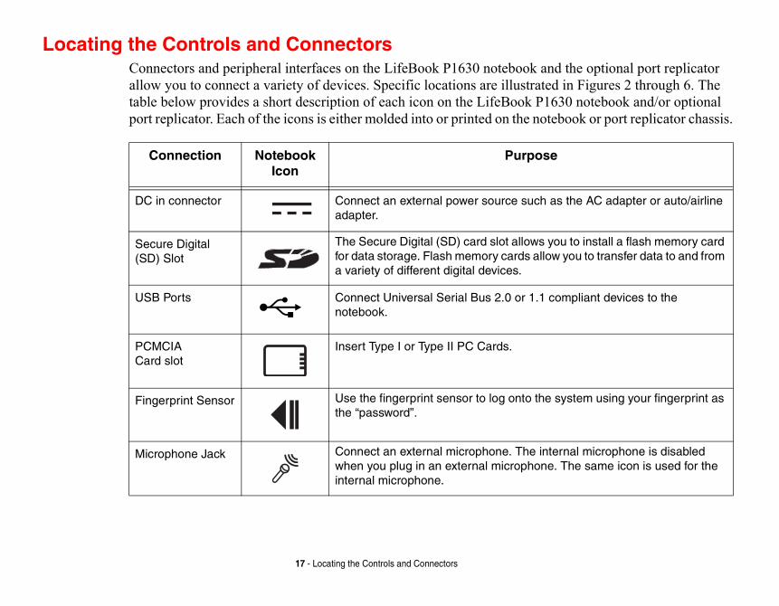
Locating the Controls and ConnectorsConnectors and peripheral interfaces on the LifeBook P1630 notebook anallow you to connect a variety of devices. Specific locations are illustratetable below provides a short description of each icon on the LifeBook P16port replicator. Each of the icons is either molded into or printed on the note
Connection Notebook Icon
Purpose
DC in connector Connect an external power source such aadapter.
Secure Digital (SD) Slot
The Secure Digital (SD) card slot allows yfor data storage. Flash memory cards alloa variety of different digital devices.
USB Ports Connect Universal Serial Bus 2.0 or 1.1 cnotebook.
PCMCIA Card slot
Insert Type I or Type II PC Cards.
Fingerprint Sensor Use the fingerprint sensor to log onto thethe “password”.
Microphone Jack Connect an external microphone. The intwhen you plug in an external microphoneinternal microphone.
external speakers. The internal rnal headphones or powered
odem using a standard RJ-11
notebook using compatible
to suspend notebook activity ok from suspend mode, and ut down from Windows.
the internal 10/100 Base-T/Tx n your office or home, or m, DSL, or satellite Internet.
move the battery from your
rn power to the optional wireless
18 - Locating the Controls and Connectors
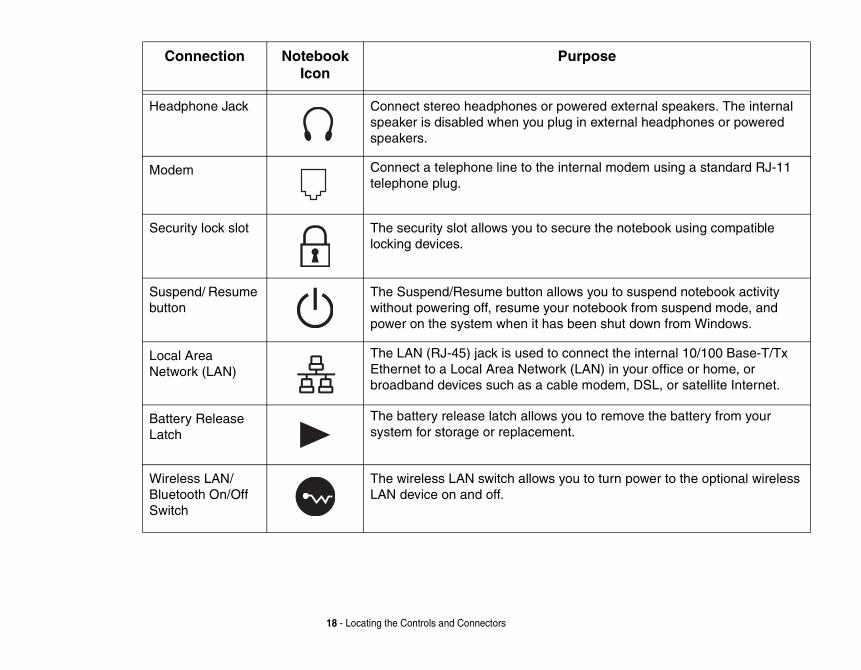
Headphone Jack Connect stereo headphones or powered speaker is disabled when you plug in extespeakers.
Modem Connect a telephone line to the internal mtelephone plug.
Security lock slot The security slot allows you to secure thelocking devices.
Suspend/ Resume button
The Suspend/Resume button allows you without powering off, resume your notebopower on the system when it has been sh
Local Area Network (LAN)
The LAN (RJ-45) jack is used to connect Ethernet to a Local Area Network (LAN) ibroadband devices such as a cable mode
Battery Release Latch
The battery release latch allows you to resystem for storage or replacement.
Wireless LAN/ Bluetooth On/Off Switch
The wireless LAN switch allows you to tuLAN device on and off.
Connection Notebook Icon
Purpose
Display Panel
Power/Suspend/Resume Button
y Panel Latch
atus Indicator Panel
1.3 MegapixelWeb Camera
19 - Locating the Controls and Connectors
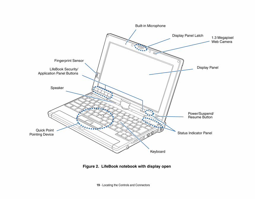
Figure 2. LifeBook notebook with display open
Speaker
Keyboard
LifeBook Security/Application Panel Buttons
Quick PointPointing Device
Fingerprint Sensor
Built-in Microphone
Displa
St
isplay features.
d over the internet. For rcSoft WebCam Companion
text and graphics and touch
powering off, resume your own from the Windows
ponents of your LifeBook
page 37.
oll button, and a cursor nting Device/Touch Screen”
20 - Locating the Controls and Connectors
Front and Display ComponentsThe following is a brief description of your LifeBook notebook’s front and d
Display Panel Latch
The display panel latch holds the display panel in position.
Web Camera
The 1.3 megapixel web camera allows you to take pictures of yourself to seninformation on using the camera, see the documentation associated with the Aapplication.
Display Panel
The display panel is a color LCD panel with back lighting for the display ofscreen functionality.
Suspend/Resume Button
The Suspend/Resume button allows you to suspend system activity without system from sleep mode, and power on your system when it has been shut doperating system. See “Power On” on page 61.
Status Indicator Panel
The Status Indicator Panel displays symbols that correspond to specific comP1630 notebook. See “Status Indicator Panel” on page 29.
Keyboard
A full-function keyboard with dedicated Windows keys. See “Keyboard” on
Quick Point Pointing Device
The Quick Point pointing device consists of two mouse-like buttons, one scrcontrol button (located near the center of the keyboard). See “Quick Point Poion page 40.
tion launch capabilities. See
plications by replacing your age 170.
21 - Locating the Controls and Connectors
Speaker
The speaker allows you to listen to sound from your system.
LifeBook Security/Application Buttons
The LifeBook P1630 notebook Security/Application Buttons provide applica“LifeBook Security/Application Panel” on page 48.
Fingerprint Sensor
The fingerprint recognition sensor allows you to log into Windows or other apusername and password. See “Appendix B: Fingerprint Sensor Device” on p
Built-in Microphone
The built-in microphone allows you to input mono audio.
omponents.
ional WLAN and Bluetooth life. See “Activating the
Cards” on page 86.
n
22 - Locating the Controls and Connectors
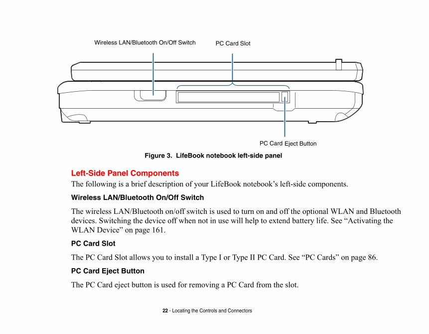
Figure 3. LifeBook notebook left-side panel
Left-Side Panel ComponentsThe following is a brief description of your LifeBook notebook’s left-side c
Wireless LAN/Bluetooth On/Off Switch
The wireless LAN/Bluetooth on/off switch is used to turn on and off the optdevices. Switching the device off when not in use will help to extend batteryWLAN Device” on page 161.
PC Card Slot
The PC Card Slot allows you to install a Type I or Type II PC Card. See “PC
PC Card Eject Button
The PC Card eject button is used for removing a PC Card from the slot.
PC Card Slot
PC Card Eject Butto
Wireless LAN/Bluetooth On/Off Switch
components.
r data storage. Flash memory ices.
xternal speakers. See
See “Microphone Jack” on
k
DC Power Jack
23 - Locating the Controls and Connectors
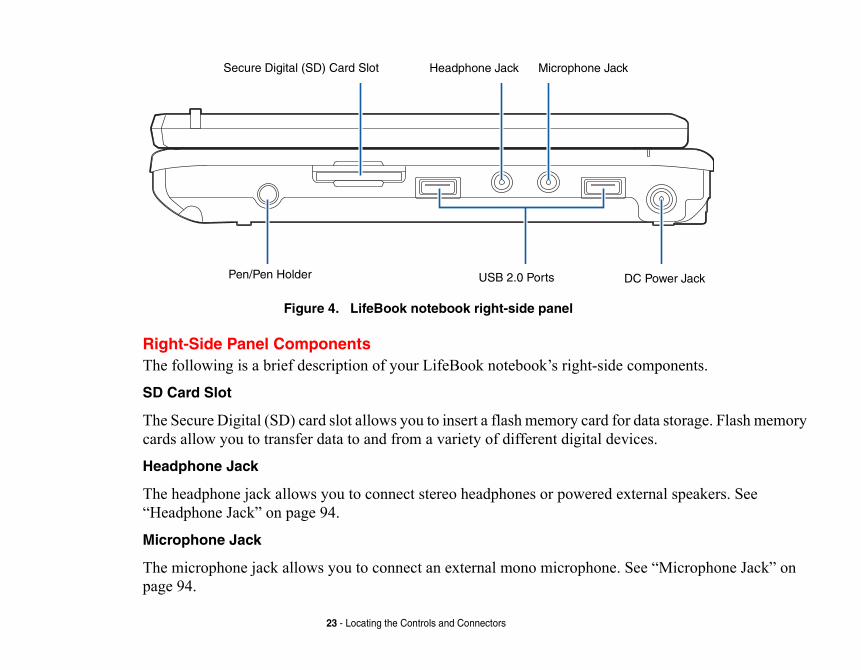
Figure 4. LifeBook notebook right-side panel
Right-Side Panel ComponentsThe following is a brief description of your LifeBook notebook’s right-side
SD Card Slot
The Secure Digital (SD) card slot allows you to insert a flash memory card focards allow you to transfer data to and from a variety of different digital dev
Headphone Jack
The headphone jack allows you to connect stereo headphones or powered e“Headphone Jack” on page 94.
Microphone Jack
The microphone jack allows you to connect an external mono microphone. page 94.
Pen/Pen Holder
Microphone JacHeadphone Jack
USB 2.0 Ports
Secure Digital (SD) Card Slot
uto/Airline adapter to power
. USB 2.0 transfers data at up ansfer data at up to 12 Mbps.
en from the pen holder, press
24 - Locating the Controls and Connectors
DC Power Jack
The DC power jack allows you to plug in the AC adapter or the optional Ayour system and charge the internal Lithium ion Battery.
USB 2.0 Ports
The two USB 2.0 ports allow you to connect Universal Serial Bus devicesto 480 Mbps and is backward-compatible with USB 1.1 devices, which trSee “Universal Serial Bus Ports” on page 93.
Pen/Pen Holder
The pen is used as the interface with the digitizer display. To release the pthe pen towards the system; it will pop out when you release it.
components.
projector. Note that when the al video port on the Port n page 94.
x Ethernet. See “Internal LAN
25 - Locating the Controls and Connectors
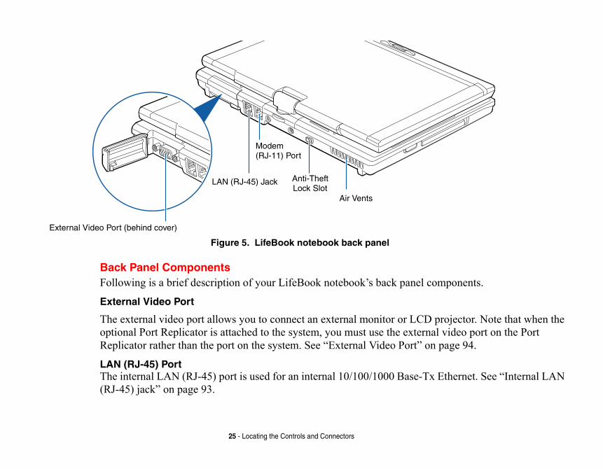
Figure 5. LifeBook notebook back panel
Back Panel ComponentsFollowing is a brief description of your LifeBook notebook’s back panel
External Video Port
The external video port allows you to connect an external monitor or LCDoptional Port Replicator is attached to the system, you must use the externReplicator rather than the port on the system. See “External Video Port” o
LAN (RJ-45) Port The internal LAN (RJ-45) port is used for an internal 10/100/1000 Base-T(RJ-45) jack” on page 93.
LAN (RJ-45) Jack Anti-Theft
Air Vents
External Video Port (behind cover)
Lock Slot
Modem(RJ-11) Port
internal multinational 56K
device.
ot overheat.
ITH DIGITAL PBX SYSTEMS. DO CAUSE SERIOUS DAMAGE TO THE BOOK. CONSULT YOUR PBX VE DIGITAL PBX SYSTEMS. BE
. ITS MAXIMUM SPEED OF 53000 ON RATE DEPENDS ON THE LINE
STEM PERFORMANCE, BE SURE TO EBRIS. THIS MAY REQUIRE
H THE SYSTEM IS USED.
CAN BE OBSTRUCTED, SUCH AS IN N.
26 - Locating the Controls and Connectors
Modem (RJ-11) Telephone Port The Modem (RJ-11) telephone port is for attaching a telephone line to themodem.
Anti-theft Lock Slot
The anti-theft lock slot allows you to attach a optional physical lock-down
Air Vents
The air vents allow proper air circulation to ensure that the system does n
THE INTERNAL MULTINATIONAL MODEM IS NOT INTENDED FOR USE WNOT CONNECT THE INTERNAL MODEM TO A DIGITAL PBX AS IT MAY
INTERNAL MODEM OR YOUR ENTIRE LIFEBOOK P1630 SERIES NOTE
MANUFACTURER’S DOCUMENTATION FOR DETAILS. SOME HOTELS HA
SURE TO FIND OUT BEFORE YOU CONNECT YOUR MODEM.
THE INTERNAL MODEM IS DESIGNED TO THE ITU-T V.90 STANDARD
BPS IS THE HIGHEST ALLOWED BY FCC, AND ITS ACTUAL CONNECTI
CONDITIONS. THE MAXIMUM SPEED IS 33600 BPS AT UPLOAD.
TO PROTECT YOUR NOTEBOOK FROM DAMAGE AND TO OPTIMIZE SY
KEEP ALL AIR ALL VENTS UNOBSTRUCTED, CLEAN, AND CLEAR OF DPERIODIC CLEANING, DEPENDING UPON THE ENVIRONMENT IN WHIC
DO NOT OPERATE THE NOTEBOOK IN AREAS WHERE THE AIR VENTS
TIGHT ENCLOSURES OR ON SOFT SURFACES LIKE A BED OR CUSHIO
nel components.
bay.
ld be removed when the ttery with a charged Lithium
Memory Upgrade Compartment
Lithium ion
Port Replicator Connector
Battery
Air Vents
27 - Locating the Controls and Connectors
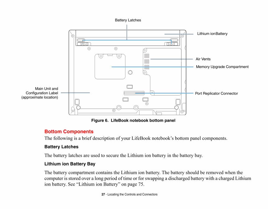
Figure 6. LifeBook notebook bottom panel
Bottom ComponentsThe following is a brief description of your LifeBook notebook’s bottom pa
Battery Latches
The battery latches are used to secure the Lithium ion battery in the battery
Lithium ion Battery Bay
The battery compartment contains the Lithium ion battery. The battery shoucomputer is stored over a long period of time or for swapping a discharged baion battery. See “Lithium ion Battery” on page 75.
Battery Latches
Main Unit andConfiguration Label
(approximate location)
mponents.
(SDRAM). The memory your system, hence improving
bout your LifeBook P1630 number and manufacturer ies the exact version of various
TEM PERFORMANCE, BE SURE TO EBRIS. THIS MAY REQUIRE THE SYSTEM IS USED.
AN BE OBSTRUCTED, SUCH AS IN .
28 - Locating the Controls and Connectors
Air Vents
The air vents allow air to circulate through the system to cool down the co
Memory Upgrade Compartment
Your notebook comes with high speed DDR2 Synchronous Dynamic RAMupgrade compartment allows you to expand the system memory capacity ofoverall performance. See “Memory Upgrade Module” on page 80.
Port Replicator Connector
This connector allows you to connect the optional port replicator.
Main Unit and Configuration Label
The configuration label shows the model number and other information anotebook. In addition, the configuration portion of the label has the serialinformation that you will need to give your support representative. It identifcomponents of your system.
TO PROTECT YOUR NOTEBOOK FROM DAMAGE AND TO OPTIMIZE SYS
KEEP ALL AIR ALL VENTS UNOBSTRUCTED, CLEAN, AND CLEAR OF DPERIODIC CLEANING, DEPENDING UPON THE ENVIRONMENT IN WHICH
DO NOT OPERATE THE NOTEBOOK IN AREAS WHERE THE AIR VENTS CTIGHT ENCLOSURES OR ON SOFT SURFACES LIKE A BED OR CUSHION
of your notebook. (Figure 7) yboard-related indicators
cator
29 - Status Indicator Panel
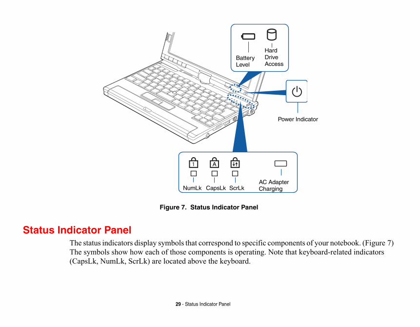
Figure 7. Status Indicator Panel
Status Indicator PanelThe status indicators display symbols that correspond to specific componentsThe symbols show how each of those components is operating. Note that ke(CapsLk, NumLk, ScrLk) are located above the keyboard.
Hard
NumLk CapsLk ScrLk
Battery Level
Drive Access
Power Indi
AC AdapterCharging
r system is operational. When y for use.
lled and charging, and how
ter or replaced with a charged
ATURES CAN BE PERMANENTLY
OT CONNECTED, THE BATTERY
30 - Status Indicator Panel
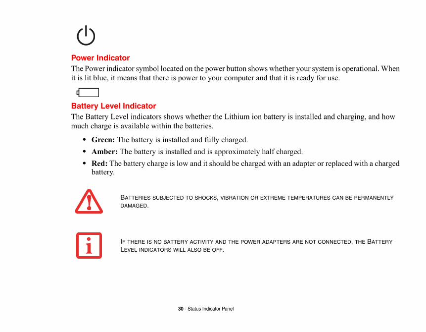
Power IndicatorThe Power indicator symbol located on the power button shows whether youit is lit blue, it means that there is power to your computer and that it is read
Battery Level IndicatorThe Battery Level indicators shows whether the Lithium ion battery is instamuch charge is available within the batteries.
• Green: The battery is installed and fully charged.• Amber: The battery is installed and is approximately half charged.• Red: The battery charge is low and it should be charged with an adap
battery.
BATTERIES SUBJECTED TO SHOCKS, VIBRATION OR EXTREME TEMPER
DAMAGED.
IF THERE IS NO BATTERY ACTIVITY AND THE POWER ADAPTERS ARE NLEVEL INDICATORS WILL ALSO BE OFF.
ve is being accessed.
umeric keypad mode.
ital letters.
31 - Status Indicator Panel
Hard Drive Access IndicatorThe Hard Drive Access indicator lights green when your internal hard dri
NumLk IndicatorThe NumLk indicator shows that the integral keyboard is set in ten-key n
CapsLock IndicatorThe CapsLock indicator shows that your keyboard is set to type in all cap
ScrLk IndicatorThe ScrLk indicator shows that your scroll lock is active.
pen the display fully, rotate it ows you to use the system as a
r fingers, until it is at a
Display Cover
32 - Display Panel
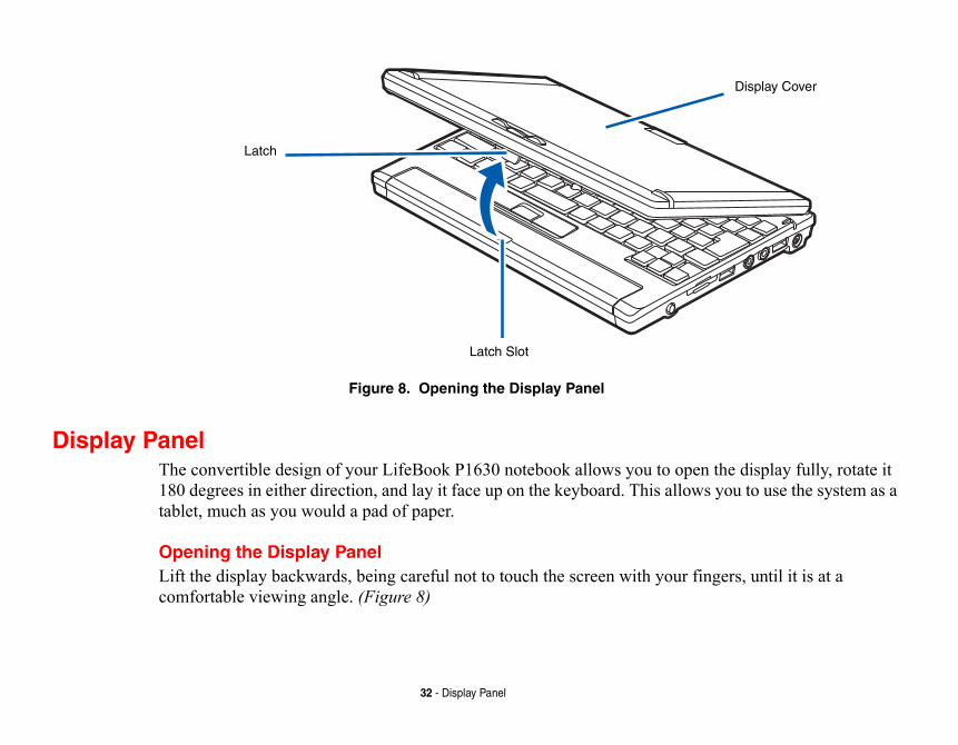
Figure 8. Opening the Display Panel
Display PanelThe convertible design of your LifeBook P1630 notebook allows you to o180 degrees in either direction, and lay it face up on the keyboard. This alltablet, much as you would a pad of paper.
Opening the Display PanelLift the display backwards, being careful not to touch the screen with youcomfortable viewing angle. (Figure 8)
Latch
Latch Slot
s.
ither direction so that it is facing
atop the keyboard.
ENDICULAR TO THE KEYBOARD, HED.
ng the Display Latch
A
B
Display Side
33 - Display Panel
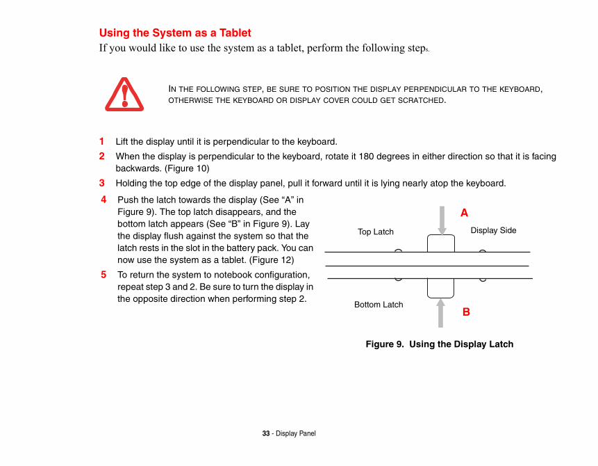
Using the System as a TabletIf you would like to use the system as a tablet, perform the following step
1 Lift the display until it is perpendicular to the keyboard.
2 When the display is perpendicular to the keyboard, rotate it 180 degrees in ebackwards. (Figure 10)
3 Holding the top edge of the display panel, pull it forward until it is lying nearly
IN THE FOLLOWING STEP, BE SURE TO POSITION THE DISPLAY PERP
OTHERWISE THE KEYBOARD OR DISPLAY COVER COULD GET SCRATC
4 Push the latch towards the display (See “A” in Figure 9). The top latch disappears, and the bottom latch appears (See “B” in Figure 9). Lay the display flush against the system so that the latch rests in the slot in the battery pack. You can now use the system as a tablet. (Figure 12)
5 To return the system to notebook configuration, repeat step 3 and 2. Be sure to turn the display in the opposite direction when performing step 2.
Figure 9. Usi
Top Latch
Bottom Latch
Rotating the display
ablet configuration
Landscape Orientation
Primary Portrait Orientation
34 - Display Panel
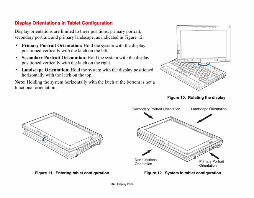
Display Orientations in Tablet Configuration
Display orientations are limited to three positions: primary portrait, secondary portrait, and primary landscape, as indicated in Figure 12.
• Primary Portrait Orientation: Hold the system with the display positioned vertically with the latch on the left.
• Secondary Portrait Orientation: Hold the system with the display positioned vertically with the latch on the right.
• Landscape Orientation: Hold the system with the display positioned horizontally with the latch on the top.
Note: Holding the system horizontally with the latch at the bottom is not a functional orientation.
Figure 10.
Figure 11. Entering tablet configuration Figure 12. System in t
Secondary Portrait Orientation
Non-functionalOrientation
level of the screen to a more yboard, power management hange the brightness using
.y.
sic View, select it in the left ab. Set the screen brightness
click Start > Control Panel > r scenarios.
, select it in the left panel. adjacent to Display scenarios.
P SYSTEMS, THE CHANGES WILL S, THE CHANGED SETTINGS ARE G THE POWER OPTIONS UTILITY
35 - Display Panel
Adjusting Display Panel BrightnessOnce you have turned on your system, you may want to adjust the brightnesscomfortable viewing level. There are three ways to adjust the brightness, keutility, and Fujitsu menu. Additionally, in Windows Vista systems, you can cthe Power Options in the Control Panel.
Using the Keyboard to Adjust Brightness
Use the following key combinations to adjust the screen brightness:
• [Fn+F6]: Pressing repeatedly will lower the brightness of your display• [Fn+F7]: Pressing repeatedly will increase the brightness of the displa
Using Power Management to Adjust Brightness To adjust brightness with the power management utility,:
Windows XP Tablet PC: Click Start > Control Panel. If you are not in Claspanel. Double-click the Tablet and Pen Settings icon, then select the Display tslider for When plugged in and Powered by batteries scenarios.
Windows XP Pro: To adjust brightness with the power management utility, Brightness Control. Set the screen brightness slider for battery and AC powe
Windows Vista: Click Start > Control Panel. If you are not in Classic ViewDouble-click the Windows Mobility Center icon, then double-click the iconbrightness. Set the screen brightness sliders for On battery and Plugged in
NOTE THAT WHEN YOU CHANGE THE DISPLAY SETTINGS IN WINDOWS XBE RETAINED AFTER SLEEP AND RESTART. IN WINDOWS VISTA SYSTEM
TEMPORARY BY DEFAULT, BUT THEY CAN BE MADE PERMANENT BY USIN
IN THE CONTROL PANEL.
ujitsu Menu icon in the system elect Brightness Control. The the screen brightness slider for
ujitsu Menu icon in the system y Center, then double-click the On battery and Plugged in
l Panel and double-click on the l, then drag the brightness bars permanent until you decide to
HEST LEVEL BY DEFAULT. IF USING ATELY MID-LEVEL BY DEFAULT.
T PC WILL CONSUME AND THE LIFE, MAKE SURE THAT THE
36 - Display Panel
Using the Fujitsu Menu to Adjust Brightness Windows XP: To adjust brightness using the Fujitsu menu, click on the Ftray in the lower right corner of the screen. From the menu that appears, sTablet and Pen Settings window will open. Select the Display tab and set battery and AC power scenarios.
Windows Vista: To adjust brightness using the Fujitsu menu, click on the Ftray in the lower right corner of the screen. Double-click Windows Mobiliticon adjacent to Display brightness. Set the screen brightness sliders for scenarios.
Using Power Options to Adjust the Brightness (Windows Vista)
To change the brightness using the Power Options utility, open the ControPower Options icon. Select “Adjust the display brightness” in the left paneto the desired level. Note that the settings you make via this utility becomechange them again.
IF USING AC POWER, YOUR BRIGHTNESS SETTING IS SET TO ITS HIG
BATTERY POWER, YOUR BRIGHTNESS SETTING IS SET TO APPROXIM
THE HIGHER THE BRIGHTNESS LEVEL, THE MORE POWER THE TABLE
FASTER YOUR BATTERIES WILL DISCHARGE. FOR MAXIMUM BATTERY
BRIGHTNESS IS SET AS LOW AS POSSIBLE.
s perform all the standard pecial function keys. This
Back Space
yCursor Keys
37 - Keyboard
Keyboard
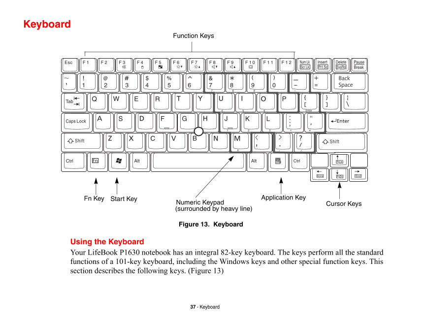
Figure 13. Keyboard
Using the KeyboardYour LifeBook P1630 notebook has an integral 82-key keyboard. The keyfunctions of a 101-key keyboard, including the Windows keys and other ssection describes the following keys. (Figure 13)
Fn Key Start Key
Function Keys
Numeric KeypadApplication Ke
(surrounded by heavy line)
ses, both as standard le between the standard
cursor or insertion point to ts. ce special actions that vary tion with the [Fn] key to
and function the same as evice.
ter keys and numeric keypad NumLk feature is done the , perform addition ( + ), . ) using the keys designated front edge of the key to
pplication key. The Start key rt menu button. The
shortcut menus for the nformation regarding the
move the cursor up, down, es the “focus” (selects the
38 - Keyboard
• Numeric keypad: Your system allows certain keys to serve dual purpocharacters and as numeric and mathematical keys. The ability to toggcharacter and numerical keys is controlled through the [NumLk] key.
• Cursor keys: Your keyboard contains four arrow keys for moving the the right, left, up, or down within windows, applications and documen
• Function keys: The keys labeled [F1] through [F12], are used to produdepending on what program is running. They are also used in conjuncperform certain tasks, as detailed below under “Function Keys”.
• Windows keys: These keys work with your Windows operating systemthe onscreen Start menu button, or the right button on your pointing d
Numeric Keypad
Certain keys on the keyboard perform dual functions as both standard charackeys. NumLk can be activated by pressing the [NumLk] key. Turning off thesame way. Once this feature is activated you can enter numerals 0 through 9subtraction ( - ), multiplication ( * ), or division ( / ), and enter decimal points (as ten-key function keys. The keys in the numeric keypad are marked on theindicate their secondary functions. (Figure 13)
Windows Keys
Your LifeBook P1630 notebook has two Windows keys: a Start key and an Adisplays the Start menu. This button functions the same as your onscreen StaApplication key functions the same as your right mouse button and displaysselected item. (Please refer to your Windows documentation for additional iWindows keys.) (Figure 13)
Cursor Keys
The cursor keys are the four arrow keys on the keyboard which allow you toleft and right in applications. In programs such as Windows Explorer, it movnext item up, down, left, or right).
ns assigned to these keys differ nd out how these keys are used.
ute on and off.ointing device on and off. Note ed in the BIOS. (See “Entering
tween video compensation and play. When it is enabled, ll still cover the entire screen.)e brightness of your display. ystem setting. the brightness of the display. the volume of your system. the volume of your system.our selection of where to send
ou will step to the next choice. itor only, and both built-in
39 - Keyboard
Function Keys
Your LifeBook notebook has 12 function keys, F1 through F12. The functiofor each application. You should refer to your software documentation to fi
• [Fn+F3]: Pressing [F3] while holding [Fn] will toggle the Audio M• [Fn+F4]: Pressing [F4] while holding [Fn] will toggle the built-in p
that the [Fn+F4] combination only works if Manual Setting is selectthe BIOS Setup Utility” on page 63)
• [Fn +F5]: Pressing [F5] while holding [Fn] allows you to toggle beno compensation. (Video compensation controls spacing on the disdisplays with less than 1024 x 600 or 800 x 600 pixel resolution wi
• [Fn+F6]: Pressing [F6] repeatedly while holding [Fn] will lower thNote that adjusting the brightness using the keyboard changes the s
• [Fn+F7]: Pressing [F7] repeatedly while holding [Fn] will increase• [Fn+F8]: Pressing [F8] repeatedly while holding [Fn] will decrease• [Fn+F9]: Pressing [F9] repeatedly while holding [Fn] will increase• [Fn+F10]: Pressing [F10] while holding [Fn] allows you to change y
your display video. Each time you press the combination of keys yThe choices, in order, are: built-in display panel only, external mondisplay panel and external monitor.
e movement of the cursor to control at the center of the ntrol works the same way a
ight pressure with the tip of The left button functions the a right mouse button. When own a screen. The actual ing used. .
40 - Quick Point Pointing Device/Touch Screen
Quick Point Pointing Device/Touch Screen
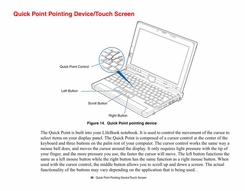
Figure 14. Quick Point pointing device
The Quick Point is built into your LifeBook notebook. It is used to control thselect items on your display panel. The Quick Point is composed of a cursorkeyboard and three buttons on the palm rest of your computer. The cursor comouse ball does, and moves the cursor around the display. It only requires lyour finger, and the more pressure you use, the faster the cursor will move. same as a left mouse button while the right button has the same function as used with the cursor control, the middle button allows you to scroll up and dfunctionality of the buttons may vary depending on the application that is be
Left Button
Right Button
Scroll Button
Quick Point Control
gure 15. Clicking
e 16. Double-clicking
L NOT BE EXECUTED.
E DIALOG BOX LOCATED IN THE
41 - Quick Point Pointing Device/Touch Screen
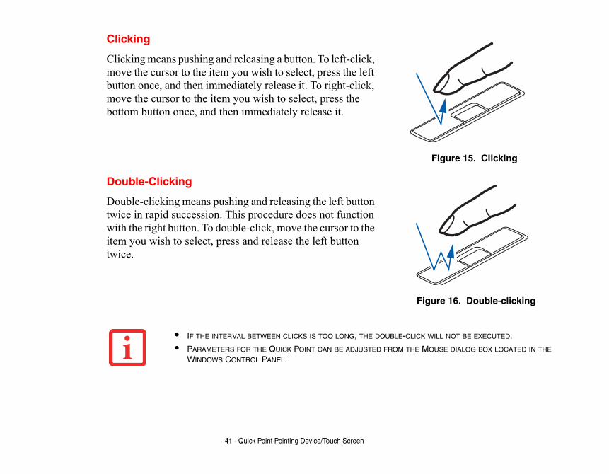
Clicking
Clicking means pushing and releasing a button. To left-click, move the cursor to the item you wish to select, press the left button once, and then immediately release it. To right-click, move the cursor to the item you wish to select, press the bottom button once, and then immediately release it.
Fi
Double-Clicking
Double-clicking means pushing and releasing the left button twice in rapid succession. This procedure does not function with the right button. To double-click, move the cursor to the item you wish to select, press and release the left button twice.
Figur
• IF THE INTERVAL BETWEEN CLICKS IS TOO LONG, THE DOUBLE-CLICK WIL
• PARAMETERS FOR THE QUICK POINT CAN BE ADJUSTED FROM THE MOUS
WINDOWS CONTROL PANEL.
th selections made from within peration, which you can adjust:
operation, in addition to setting
ing on its functionality.eed of your finger motion and for the cursor arrow.
ure 17. Dragging
42 - Quick Point Pointing Device/Touch Screen
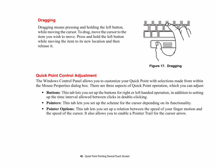
Quick Point Control AdjustmentThe Windows Control Panel allows you to customize your Quick Point withe Mouse Properties dialog box. There are three aspects of Quick Point o
• Buttons: This tab lets you set up the buttons for right or left handed up the time interval allowed between clicks in double-clicking.
• Pointers: This tab lets you set up the scheme for the cursor depend• Pointer Options: This tab lets you set up a relation between the sp
the speed of the cursor. It also allows you to enable a Pointer Trail
Dragging
Dragging means pressing and holding the left button, while moving the cursor. To drag, move the cursor to the item you wish to move. Press and hold the left button while moving the item to its new location and then release it.
Fig
Using the Touch Screen
THE SCREEN WITH THE STYLUS. /OR TOUCH SCREEN.
YTHING BUT THE INCLUDED STYLUS
FUJITSU’S ACCESSORIES WEBSITE
43 - Quick Point Pointing Device/Touch Screen
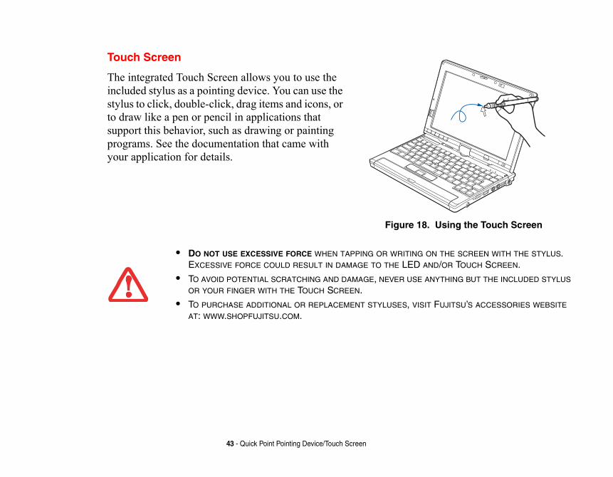
Touch Screen
The integrated Touch Screen allows you to use the included stylus as a pointing device. You can use the stylus to click, double-click, drag items and icons, or to draw like a pen or pencil in applications that support this behavior, such as drawing or painting programs. See the documentation that came with your application for details.
Figure 18.
• DO NOT USE EXCESSIVE FORCE WHEN TAPPING OR WRITING ON
EXCESSIVE FORCE COULD RESULT IN DAMAGE TO THE LED AND
• TO AVOID POTENTIAL SCRATCHING AND DAMAGE, NEVER USE AN
OR YOUR FINGER WITH THE TOUCH SCREEN.
• TO PURCHASE ADDITIONAL OR REPLACEMENT STYLUSES, VISIT AT: WWW.SHOPFUJITSU.COM.
g the Touch Screen
nal Edition:
mplished by holding the ar icon appears. To he right-click feature, go l > Touch Panel. From tion tab you can specify ing the selected button t mouse click.
44 - Quick Point Pointing Device/Touch Screen
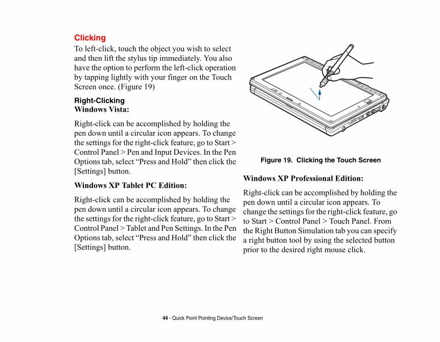
ClickingTo left-click, touch the object you wish to select and then lift the stylus tip immediately. You also have the option to perform the left-click operation by tapping lightly with your finger on the Touch Screen once. (Figure 19)
Right-Clicking Windows Vista:
Right-click can be accomplished by holding the pen down until a circular icon appears. To change the settings for the right-click feature, go to Start > Control Panel > Pen and Input Devices. In the Pen Options tab, select “Press and Hold” then click the [Settings] button.
Windows XP Tablet PC Edition:
Right-click can be accomplished by holding the pen down until a circular icon appears. To change the settings for the right-click feature, go to Start > Control Panel > Tablet and Pen Settings. In the Pen Options tab, select “Press and Hold” then click the [Settings] button.
Figure 19. Clickin
Windows XP Professio
Right-click can be accopen down until a circulchange the settings for tto Start > Control Panethe Right Button Simulaa right button tool by usprior to the desired righ
t run the Touch Screen er you change the display
lassic View” in the left panel.
-clicking the Touch Screen
ging on the Touch Screen
45 - Quick Point Pointing Device/Touch Screen
Calibrating the Touch ScreenIn order to ensure accurate tracking between the stylus and cursor, you musCalibration Utility before you use the Touch Screen for the first time, or aftresolution.
To run the calibration utility:1 Go to Start > Control Panel. If you are not in Classic View, select “Switch to C
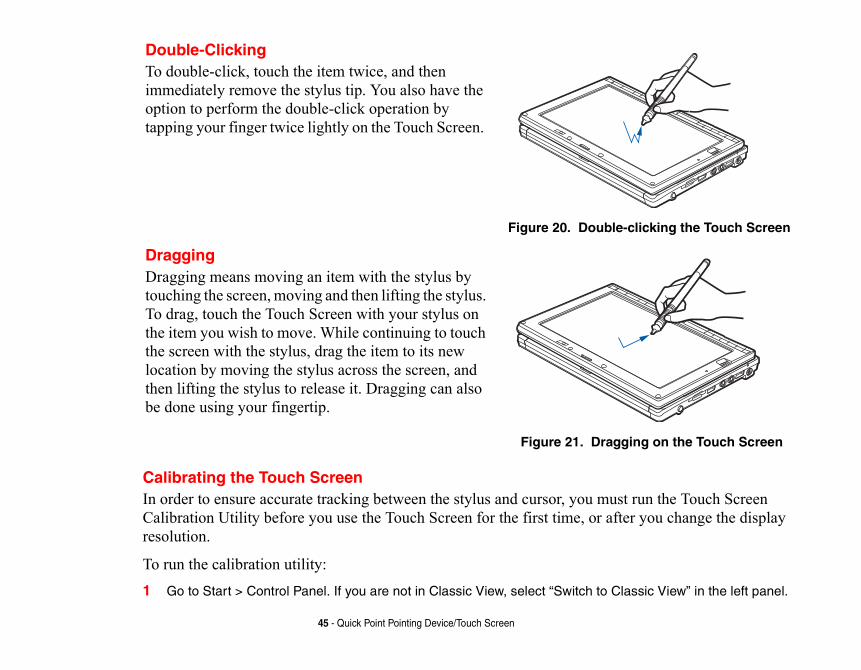
Double-ClickingTo double-click, touch the item twice, and then immediately remove the stylus tip. You also have the option to perform the double-click operation by tapping your finger twice lightly on the Touch Screen.
Figure 20. Double
DraggingDragging means moving an item with the stylus by touching the screen, moving and then lifting the stylus. To drag, touch the Touch Screen with your stylus on the item you wish to move. While continuing to touch the screen with the stylus, drag the item to its new location by moving the stylus across the screen, and then lifting the stylus to release it. Dragging can also be done using your fingertip.
Figure 21. Drag
con and select the Settings tab. select the Calibration tab. neral tab.
ymbol in the upper-left corner of
lus from the screen and the target
orrectly calibrated. If you are not gain.
RING CALIBRATION. USE OF /OR TOUCH PANEL.
AVOID TOUCHING THE SCREEN TION.
46 - Quick Point Pointing Device/Touch Screen
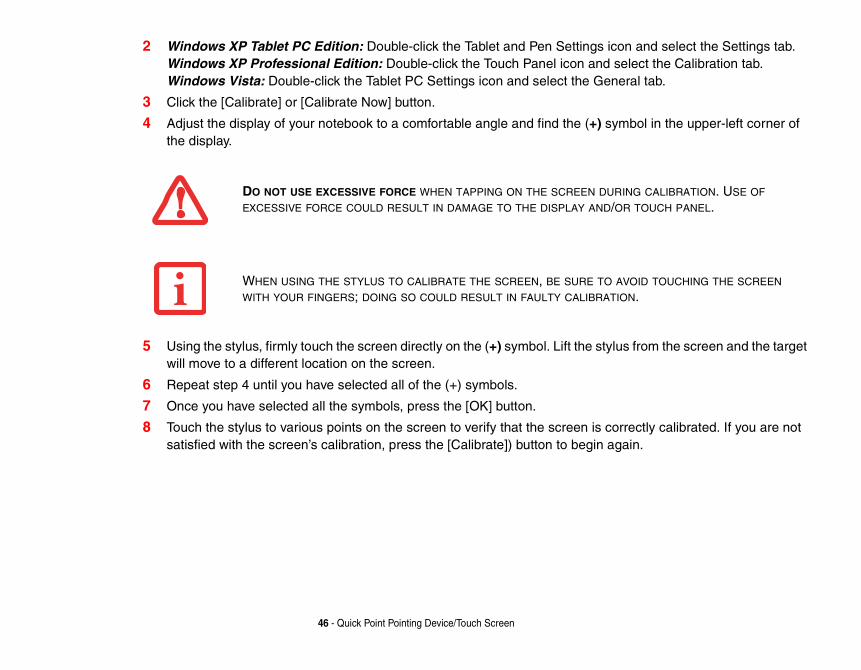
2 Windows XP Tablet PC Edition: Double-click the Tablet and Pen Settings iWindows XP Professional Edition: Double-click the Touch Panel icon andWindows Vista: Double-click the Tablet PC Settings icon and select the Ge
3 Click the [Calibrate] or [Calibrate Now] button.
4 Adjust the display of your notebook to a comfortable angle and find the (+) sthe display.
5 Using the stylus, firmly touch the screen directly on the (+) symbol. Lift the stywill move to a different location on the screen.
6 Repeat step 4 until you have selected all of the (+) symbols.
7 Once you have selected all the symbols, press the [OK] button.
8 Touch the stylus to various points on the screen to verify that the screen is csatisfied with the screen’s calibration, press the [Calibrate]) button to begin a
DO NOT USE EXCESSIVE FORCE WHEN TAPPING ON THE SCREEN DU
EXCESSIVE FORCE COULD RESULT IN DAMAGE TO THE DISPLAY AND
WHEN USING THE STYLUS TO CALIBRATE THE SCREEN, BE SURE TO
WITH YOUR FINGERS; DOING SO COULD RESULT IN FAULTY CALIBRA
47 - Volume Control
Volume ControlYour Fujitsu LifeBook notebook has multiple volume controls which interact with each other.
Controlling the VolumeThe volume can be controlled in several different ways:
• Volume can be set from within the Volume Control in the Notification Area at the bottom right of your screen.
• Volume can be controlled with the [F8] and [F9] functions keys. Pressing [F8] repeatedly while holding [Fn] will decrease the volume of your notebook. Pressing [F9] repeatedly while holding [Fn] will increase the volume of your notebook.
• Volume can be controlled by many volume controls that are set within individual applications.• Certain external audio devices you might connect to your system may have hardware volume
controls.Each source discussed above puts an upper limit on the volume level that must then be followed by the other sources. We recommend that you experiment with the various volume controls to discover the optimal sound level.
ANY SOFTWARE THAT CONTAINS AUDIO FILES WILL ALSO CONTAIN A VOLUME CONTROL OF ITS OWN. IF YOU INSTALL AN EXTERNAL AUDIO DEVICE THAT HAS AN INDEPENDENT VOLUME CONTROL, THE HARDWARE VOLUME CONTROL AND THE SOFTWARE VOLUME CONTROL WILL INTERACT WITH EACH OTHER. IT SHOULD BE NOTED THAT IF YOU SET YOUR SOFTWARE VOLUME TO OFF, YOU WILL OVERRIDE THE EXTERNAL VOLUME CONTROL SETTING.
el that allows you to secure allows you to launch
from suspend mode the Security/Application Panel. .
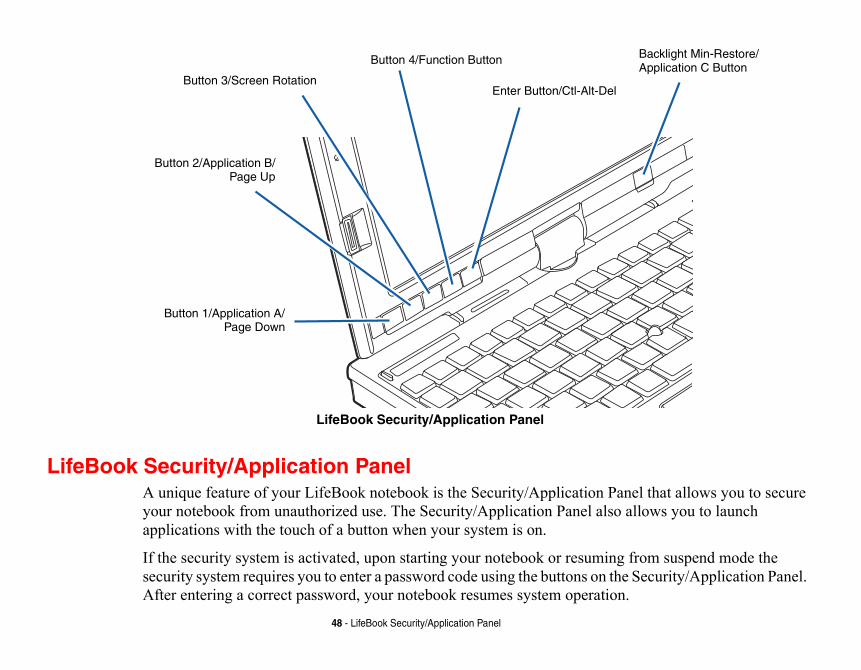
Backlight Min-Restore/Application C Button
48 - LifeBook Security/Application Panel
LifeBook Security/Application Panel
LifeBook Security/Application PanelA unique feature of your LifeBook notebook is the Security/Application Panyour notebook from unauthorized use. The Security/Application Panel also applications with the touch of a button when your system is on.
If the security system is activated, upon starting your notebook or resuming security system requires you to enter a password code using the buttons on theAfter entering a correct password, your notebook resumes system operation
Button 3/Screen Rotation
Button 1/Application A/Page Down
Button 2/Application B/Page Up
Button 4/Function Button
Enter Button/Ctl-Alt-Del
is pre-installed without any curity panel, and how to set,
o the LifeBook notebook.
or password is typically the llow for system management. mmon password. A password consists of pushing one or up
tton strokes using more than
49 - LifeBook Security/Application Panel
Setting up Your LifeBook Security PanelWhen you receive your LifeBook notebook, the security panel application passwords. The following sections provide detailed information on your sechange or remove passwords.
Numbered Buttons
Use these buttons to enter your password.
Enter Button
After entering the button strokes, push this button to enter the password int
PasswordsThe user and supervisor password may be set on this notebook. A supervissame for all LifeBook notebooks in a working group, office, or company to aIndividual LifeBook notebooks in a group environment should not use a coconsists of one to five button strokes plus the [Enter] button. A valid stroke to four buttons simultaneously. The following are valid button strokes:
• Pushing [4] by itself• Pushing [2] and [3] at the same time• Pushing [1], [2], and [4] at the same time• Pushing [1], [2], [3], and [4] at the same time
The following are valid passwords. The numbers within braces ({ }) are buone button.
• {[2]+[3]}, [1], [enter]• [4], [enter]• {[1]+[3]}, {[2]+[3]+[4]}, [1], [4], [2], [enter]
aving no password or setting e the user password.
The supervisor password can ppropriate procedure below.
isor\FJSECS.EXE, then
isor\FJSECS.EXE, then
THE USER PASSWORD IN CASE ONE WILL NOT LOCK THE
E SECURITY PANEL TO WORK.
50 - LifeBook Security/Application Panel
Setting Passwords When shipped from the factory, no passwords are set. You have a choice of hsupervisor and user passwords. You must set the supervisor password befor
Setting Supervisor Password
You must have set a supervisor password before setting any user passwords. bypass the user password. Depending upon your operating system, use the a
Windows XP:1 Go to the Start menu.
2 Click on Run.
3 Type in: C:\Program Files\Fujitsu\Security Panel Application\Supervpress [Enter]
4 Follow the on-screen instructions to set the Supervisor password.
Windows Vista:1 Go to the Start menu.
2 Select All Programs.
3 Select Accessories, then select Run.
4 Type in: C:\Program Files\Fujitsu\Security Panel Application\Supervpress [Enter]
5 Follow the on-screen instructions to set the Supervisor password.
THE PURPOSE OF SUPERVISOR PASSWORD IS TO BE ABLE TO BYPASS THE USER PASSWORD IS FORGOTTEN. THE SUPERVISOR PASSWORD AL
SYSTEM.
YOU MUST SET BOTH THE SUPERVISOR AND USER PASSWORDS FOR TH
Off or suspend state. You will tton. Your system will not boot
tton. For example, if the password
RD BY REPEATING THE STEPS
51 - LifeBook Security/Application Panel
Setting User Password Windows XP:
1 Go to the Start menu.
2 Click on Programs.
3 Click on Security Panel Application and Set User Password.
4 Follow the on-screen instructions to set the user password
Windows Vista:1 Go to the Start menu.
2 Select All Programs.
3 Select Security Panel Application and Set User Password.
4 Follow instructions to set the user password.
Operating Your LifeBook Security/Application PanelThe security lock feature is in effect both when the system resumes from need to enter the user password right after pressing the Suspend/Resume buor resume from Sleep without entering your supervisor/user password.
From Off State 1 Turn on your system.
2 When the Security Indicator flashes, enter the password and press [Enter] buis 22222, press button number [2] five times and press [Enter] button.
3 The notebook will boot to normal operation.
YOU MAY CHANGE OR REMOVE THE SUPERVISOR OR USER PASSWO
DEFINED ABOVE.
ton.
n, the system will “beep” for tem beeps), the beeping will invalid one) is entered while r off) and the Security u must press the
ing the cover does not nter the proper security be changed in the Power
ume button only turns on the rns off after one minute. To ou may unlock the notebook.
PANEL APPLICATION. IF YOU TER. THE SUPERVISOR
52 - LifeBook Security/Application Panel
From Sleep State 1 Press your Power/Suspend/Resume button.
2 When the Security Indicator flashes, enter the password and press [Enter] but
3 The notebook should resume normal operation.
Incorrect Password Entry If an invalid supervisor or user password is entered three times in successioabout one minute. If a valid password is entered within a minute (while sysstop and the notebook will resume normal operation. If no password (or an the system beeps, the system will return to its previous locked state (Sleep oIndicator will go off. To reactivate the notebook after a password failure, yoPower/Suspend/Resume button, then enter a correct password.
Precautions
Opening and Closing the Cover
Closing the cover automatically places the notebook into sleep mode. Openautomatically place the notebook into normal operation. Instead, you must epassword after pushing the Power/Suspend/Resume button. This setting canOptions Control Panel.
Low Battery Operations
If your LifeBook notebook has low battery, pushing the Power/Suspend/ResSecurity Indicator. Your notebook does not unlock, the Security Indicator turesume normal operation, first attach a power supply to the notebook. Then y
REMEMBER THE USER PASSWORD YOU SPECIFIED ON THE SECURITY FORGET THE PASSWORD YOU WILL NOT BE ABLE TO USE YOUR COMPU
PASSWORD CAN OVERRIDE THE USER PASSWORD.
l security features.is will not allow any changes
r and doesn’t want to give ords (supervisor, user, or
lication. To clear passwords, ove], enter current password
ontrol Panel.
nd click Add/Remove.
SIMPLY REMOVES THE UTILITY YOU MUST REINSTALL THE
53 - LifeBook Security/Application Panel
Uninstalling the Security Panel ApplicationYou have two options when uninstalling the security panel application:
• Uninstall the security panel application software. This will disable al• Uninstall the security panel application with password still active. Th
to the password. Uninstalling the Security Panel Application
Remove passwords when the User wants no password protection whatsoeveanybody the utility to set a password on their computer. In this case, if passwboth) are set, the passwords must first be cleared BEFORE removing the appfollow same procedure in “Setting Passwords” except this time, select [Remthen click [Next]. When asked to confirm, select [Yes].
Removing Security Panel Application with Passwords Still Active Using this feature will not allow any changes to the password.
User: 1 Go to Start Menu, Click on Control Panel.
2 Open Add or Remove Programs (In Vista: Programs and Features) in the C
3 Select the Security Panel Application (In Vista: Security Panel) in the list, a
4 When the Confirm File Deletion box appears, click Yes.
Supervisor:
1 Go to Start Menu, Click on Control Panel.
2 Open Add/Remove Programs Properties in the Control Panel.
REMOVING THE APPLICATIONS DOES NOT REMOVE THE PASSWORD. ITTO CHANGE/ADD/REMOVE PASSWORDS. TO CHANGE YOUR PASSWORD
APPLICATION.

el for Supervisor) in the list,
rs and Applications CD. The upervisor and User. The
se folders. d double-click the setupS.exe stalling Security Panel
ble-click the setup.exe file.(In Application window will appear.
SECS.exe and FJSECU.exe st setting a supervisor Follow instructions under
n Service and Support at 1-harges a service fee for ve a valid credit card and ship your notebook.
ay and when it is configured side of the display adjacent
54 - LifeBook Security/Application Panel
3 Select the Security Panel Application for Supervisor (In Vista: Security Panand click Add/Remove.
4 When the Confirm File Deletion box appears, click Yes.
Reinstalling the Security/Application Panel
To reinstall supervisor or user security application, you will need your DriveUtilities/Security Application Panel folder contains two separate folders: Ssetup files for supervisor and user security applications are contained in tho1 Go to the Utilities/Security Application Pane/Supervisor folder on the CD an
file. (In Vista, the path is: Utilities/SAP/Vista/Supervisor/SetupS.exe). The InApplication window will appear. Follow the instructions on the screen.
2 Go to the Utilities/Security Application Panel/User folder on the CD and douVista, the path is: Utilities/SAP/Vista/Setup.exe) The Installing Security Panel Follow the instructions on the screen.
Supervisor and user passwords can be set via Windows software using the FJfiles, respectively. FJSECU.exe for the user password cannot run without firpassword. You need to run FJSECS.exe first to set the supervisor password.Setting Passwords on page 50.
If you forget both passwords, contact Fujitsu Computer Systems Corporatio800-8FUJITSU (1-800-838-5487). Fujitsu Computer Systems Corporation cunlocking a password restricted LifeBook notebook. When calling please haprovide proof of ownership. You will then be given instructions on where to
Launching Applications with the Security/Application PanelFive application buttons are located on the bottom left-hand side of the displto be used as a notebook. One additional button is located on the right-handto the battery indicator.
ary functions when used as nction (Fn) button while and B buttons can be
e 57.
ss of the button will scroll e documents.
pplication A button, you ault application for this
for this button.
of the button will scroll the ments.
lication A button, you will pon your operating system,
n for this button.
onfigured as a tablet. When portrait orientation; when pically use landscape n automatically changes to
55 - LifeBook Security/Application Panel
All six of the buttons have primary functions. Five of the buttons have secondapplication buttons. The secondary functions are activated by pressing the Fupressing the application button. The secondary functions of the Application Achanged to launch any application. See “Changing Button Functions” on pag
Page Down / Application A Button
When you press the Page Down button when the system is running, each prethe screen down one frame. This allows you to navigate quickly through larg
When you press the Fn button while you press then release the Page Down/Awill automatically start whichever program is assigned to the button. The defbutton is Calculator.
See “Changing Button Functions” on page 57 to select a different application
Page Up / Application B Button
When you press the Page Up button when the system is running, each press screen up one frame. This allows you to navigate quickly through large docu
When you press the Fn button while you press then release the Page Up/Appautomatically start whichever program is assigned to the button. Depending uthe default application for this button is WordPad or MS Journal.
See “Changing Button Functions” on page 57. to select a different applicatio
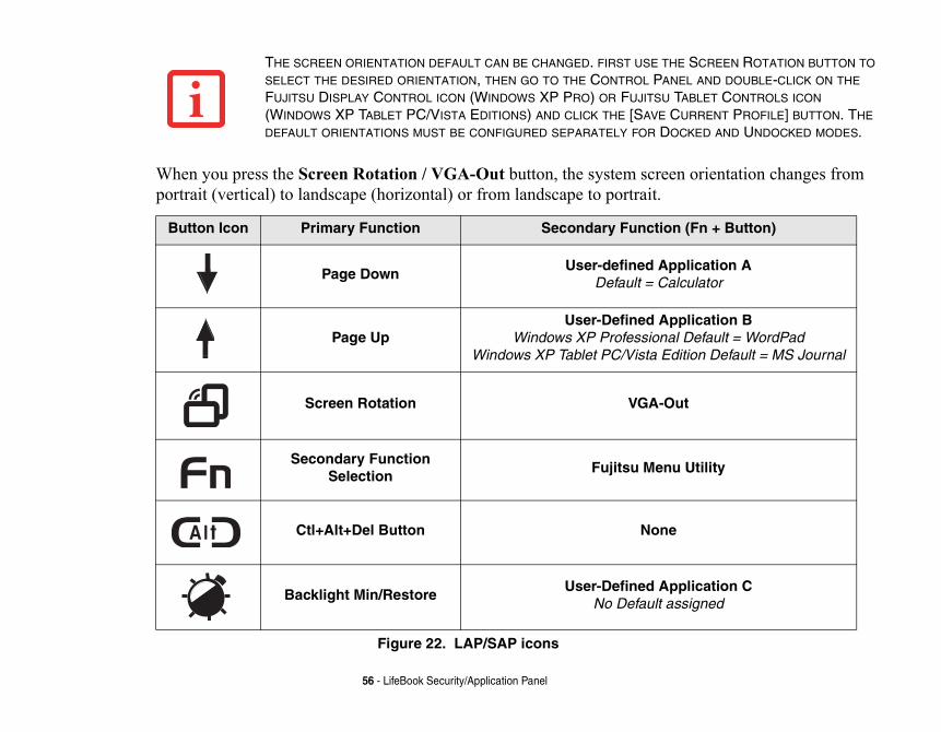
Screen Rotation / VGA-Out Button
The screen rotation feature would normally be used only when the system is cyou would like to use the tablet as an eBook, for example, you would use theaccessing spreadsheets or using the system as a notebook, you would more tyorientation. When the system is changed to tablet configuration, the orientatioportrait mode by default.
orientation changes from
SCREEN ROTATION BUTTON TO L AND DOUBLE-CLICK ON THE BLET CONTROLS ICON RRENT PROFILE] BUTTON. THE KED AND UNDOCKED MODES.
(Fn + Button)
lication Aulator
lication Befault = WordPad
ion Default = MS Journal
t
Utility
lication Cigned
56 - LifeBook Security/Application Panel
When you press the Screen Rotation / VGA-Out button, the system screenportrait (vertical) to landscape (horizontal) or from landscape to portrait.
Figure 22. LAP/SAP icons
THE SCREEN ORIENTATION DEFAULT CAN BE CHANGED. FIRST USE THE
SELECT THE DESIRED ORIENTATION, THEN GO TO THE CONTROL PANE
FUJITSU DISPLAY CONTROL ICON (WINDOWS XP PRO) OR FUJITSU TA
(WINDOWS XP TABLET PC/VISTA EDITIONS) AND CLICK THE [SAVE CU
DEFAULT ORIENTATIONS MUST BE CONFIGURED SEPARATELY FOR DOC
Button Icon Primary Function Secondary Function
Page DownUser-defined App
Default = Calc
Page UpUser-Defined App
Windows XP Professional DWindows XP Tablet PC/Vista Edit
Screen Rotation VGA-Ou
Secondary Function Selection
Fujitsu Menu
Ctl+Alt+Del Button None
Backlight Min/RestoreUser-Defined App
No Default ass
s to provide additional
o appear on your screen,
unches the Logon screen or
ing, each press of the button d as a power saving feature
in-Restore/Application C tton. There is no assigned
n for this button.
erform an action you select. ation B button launches C Edition). The Application ssigned as noted below.
tion:
57 - LifeBook Security/Application Panel
Function / Fujitsu Menu Utility Button
The Function button works in conjunction with the other application buttonfunctionality for the buttons. Refer to specific details above.
Pressing the Fn button twice in succession causes the Fujitsu Menu Utility tallowing you to modify certain system settings.
Ctl+Alt+Del Button
Pressing and holding the Ctl-Alt-Del button for approximately one second lathe Windows Task Manager (if the system hasn’t yet been configured).
Backlight Min-Restore / Application C Button
When you press the Backlight Min-Restore button when the system is runnwill toggle the backlight between minimum level and restore. This is designefor use in low-light conditions.
When you press the Fn button while you press then release the Backlight Mbutton, you will automatically start whichever program is assigned to the budefault application for this button.
See “Changing Button Functions” on page 57. to select a different applicatio
Changing Button FunctionsThe Application A, B, and C buttons can be changed to launch a program or pBy default, the Application A button launches the Calculator and the ApplicWordPad (Windows XP Professional) or MS Journal (Windows XP Tablet PC button does not have an application assigned as a default, but one can be a
To launch different applications or cause the buttons to perform a specific ac
Windows XP Tablet PC Edition:1 Double-click on the Tablet and Pen Settings icon in the Control Panel.
e from the list.
a program, click on Launch an
ave assigned to them.
a program, click on Launch an
ou have assigned to them.
the list.
a program, click on Launch an
ou have assigned to them.
58 - LifeBook Security/Application Panel
2 Select the Tablet Buttons tab and select the button you would like to chang
3 Click [Change] and open the drop down list in the Action: field.
4 Select the action you would like the button to perform. If you want to launch Application then browse to the location of the program.
Click [OK], then click [OK] again. The buttons will now perform the actions you h
Windows XP Professional:1 Double-click on the Tablet Button Settings icon in the Control Panel.
2 Select the button you would like to change from the list.
3 Click [Change] and open the drop down list in the Action: field.
4 Select the action you would like the button to perform. If you want to launch Application then browse to the location of the program.
5 Click [OK], then click [OK] again. The buttons will now perform the actions y
Windows Vista:1 Double-click on the Tablet PC Settings icon in the Control Panel.
2 Select the Buttons tab and select the button you would like to change from
3 Click [Change] and open the drop down list in the Press: field.
4 Select the action you would like the button to perform. If you want to launch Application then browse to the location of the program.
5 Click [OK], then click [OK] again. The buttons will now perform the actions y
ook
ck
ble
59
Chapter 2
Getting Started with Your LifeB
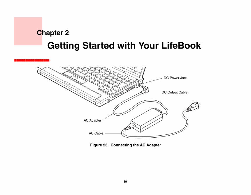
Figure 23. Connecting the AC Adapter
DC Power Ja
AC Adapter
AC Cable
DC Output Ca
ary Lithium ion battery, an AC
ating your notebook and
e ignition key in the On or Access
ttery Power
IALLY, YOU WILL NEED TO CONNECT YOUR NOTEBOOK.
60 - Power Sources
Power SourcesYour Fujitsu LifeBook notebook has three possible power sources: a primadapter or an optional Auto/Airline adapter.
Connecting the Power AdaptersThe AC adapter or optional Auto/Airline adapter provides power for opercharging the batteries.
Connecting the AC Adapter 1 Plug the DC output cable into the DC power jack of your LifeBook notebook.
2 Plug the AC adapter into an AC electrical outlet.
Connecting the Optional Auto/Airline Adapter 1 Plug the DC output cable into the DC power jack on your notebook.
2 Plug the Auto/Airline adapter into the cigarette lighter of an automobile with thOR
3 Plug the Auto/Airline adapter into the DC power jack on an airplane seat.
Switching from AC Adapter Power or the Auto/Airline Adapter to Ba
1 Be sure that you have at least one charged battery installed.
2 Remove the AC adapter or the Auto/Airline adapter.
THE LITHIUM ION BATTERY IS NOT CHARGED UPON PURCHASE. INIT
EITHER THE AC ADAPTER OR THE AUTO/AIRLINE ADAPTER TO USE
ok from its off state. Once tery, you can power on your
nd/Resume button, located leave your notebook in ff. See “Powering Off” on
OST) to check the internal Book notebook will emit an lf Test Messages” on ue by starting the operating
rating system.
A POWER SOURCE. THIS MEANS HE AC OR AUTO/AIRLINE
ON OR SUBJECT IT TO SHOCKS
61 - Starting Your LifeBook Notebook
Starting Your LifeBook Notebook
Power On
Power/Suspend/Resume Button
The Power/Suspend/Resume button is used to turn on your LifeBook noteboyou have connected your AC adapter or charged the internal Lithium ion batLifeBook notebook.
To turn on your LifeBook notebook from its off state, press the Power/Suspeabove the keyboard to the right. When you are done working you can either Suspend mode, See “Sleep (Standby) Mode” on page 70. or you can turn it opage 72..
When you power on your LifeBook, it will perform a Power On Self Test (Pparts and configuration for correct functionality. If a fault is found, your Lifeaudio warning and/or an error message will be displayed. See “Power On Sepage 108. Depending on the nature of the problem, you may be able to continsystem or by entering the BIOS setup utility and revising the settings.
After satisfactory completion of the POST, your notebook will load your ope
WHEN YOU TURN ON YOUR LIFEBOOK NOTEBOOK BE SURE YOU HAVE THAT AT LEAST ONE BATTERY IS INSTALLED AND CHARGED, OR THAT TADAPTER IS CONNECTED AND HAS POWER.
DO NOT CARRY YOUR LIFEBOOK NOTEBOOK AROUND WITH THE POWER
OR VIBRATION, AS YOU RISK DAMAGING YOUR NOTEBOOK.
e and involves your notebook’s memory is empty, and it needs IOS program. Each time you displays a Fujitsu logo until ing a standard boot sequence leted without a failure and ating system’s opening screen.
x.a new application.
your hard disk drive(s). This ty below for information about
ON SELF TEST (POST) OR IT WILL UR LIFEBOOK NOTEBOOK ON THE
ER AND MASTER HARD DISK ESET IT. YOU MAY LOSE DATA AND
62 - Starting Your LifeBook Notebook
Boot SequenceThe procedure for starting-up your notebook is termed the Bootup sequencBIOS. When your LifeBook notebook is first turned on, the main system to find instructions to start up your notebook. This information is in the Bpower up or restart your notebook, it goes through a boot sequence whichyour operating system is found. During booting, your notebook is performincluding a Power On Self Test (POST). When the boot sequence is compwithout a request for the BIOS Setup Utility, the system displays the oper
The boot sequence is executed when:
• You turn on the power to your LifeBook notebook.• You restart your notebook from the Windows Shut Down dialog bo• The software initiates a system restart. Example: When you install
Hard Disk Drive PasswordsTo provide additional security for your data, you can assign passwords tofeature is managed in the system BIOS Setup Utility. See BIOS Setup Utiliaccessing the utility.
NEVER TURN OFF YOUR LIFEBOOK NOTEBOOK DURING THE POWER
CAUSE AN ERROR MESSAGE TO BE DISPLAYED WHEN YOU TURN YO
NEXT TIME. See “Power On Self Test Messages” on page 108.
REMEMBER YOUR PASSWORDS. IF YOU SET AND FORGET YOUR US
PASSWORDS, FUJITSU COMPUTER SYSTEMS WILL NOT BE ABLE TO RHAVE TO REPLACE YOUR SYSTEM BOARD OR HARD DISK DRIVE.
t for your LifeBook notebook. here is no need to set or change
and boot devices.
enu, as detailed in the next
ars on the screen. This will open
r setup menus to review or alter
press [ENTER].
ng changes, select Yes and press
63 - Starting Your LifeBook Notebook
BIOS Setup UtilityThe BIOS Setup Utility is a program that sets up the operating environmenYour BIOS is set at the factory for normal operating conditions, therefore tthe BIOS’ environment to operate your notebook.
The BIOS Setup Utility configures:
• Device control feature parameters, such as changing I/O addresses • System Data Security feature parameters, such as passwords.
Entering the BIOS Setup Utility
To enter the BIOS Setup Utility do the following (or use the SecureCore Msection):1 Turn on or restart your LifeBook notebook.
2 To enter the BIOS Setup Utility, press the [F2] key once the Fujitsu logo appethe main menu of the BIOS Setup Utility with the current settings displayed.
3 Press the [RIGHT ARROW] or [LEFT ARROW] key to scroll through the othethe current settings.
Setting the Supervisor Password and Password on Boot Settings
1 Enter the BIOS Setup Utility.
2 Scroll to the Security Tab.
3 Select Set Supervisor Password, press [ENTER].
4 Enter New Password and confirm new password.
5 In the Security Tab, scroll to Password on Boot, and select Every Boot and
6 Press [F10]. The Save and Exit, a screen will pop up. If you are finished maki[ENTER].
n the left mouse or touchpad
ation screens:
escribed.
u logo appears on the screen.
e and support website at nder Online Support. Select lect the BIOS Guide.
ave gone through the initial
ogo on the screen. If you do elcome will begin.
e is a different procedure for
64 - Starting Your LifeBook Notebook
Using the SecureCore Menu
When the Fujitsu logo appears on the screen. press the [Enter] key or click obutton; the SecureCore Menu will appear.
The SecureCore Menu provides shortcuts to the following menus and inform
• BIOS Setup• Diagnostic Screen• Boot Menu• Patent Information• System Information• Continue Booting
Clicking on any of the fields will invoke the screen, information, or action d
The Boot Menu can also be invoked by pressing the [F12] key when the Fujits
BIOS Guide
A guide to your notebook’s BIOS is available online. Please visit our servichttp://www.computers.us.fujitsu.com/support, then select User’s Guides uyour Product, Series, and Model, then click [Go]. Under the Manuals tab, se
Booting the SystemWe strongly recommend that you not attach any external devices until you hpower on sequence.
When you turn on your notebook for the first time, it will display a Fujitsu lnothing the system will load the operating system, and then the Windows W
Depending upon your operating system (Windows Vista or XP edition), therstating your system for the first time, as outlined below.
sta operating system, it should
nts (EULAs).
given a chance to select an icon
ktop background.
default choice is "Use s only" and "Ask me later". Select
your selection from Home, Work
E SCREEN WILL BE BLANK FOR ION, A “SET UP WINDOWS” DIALOG
T THE POWER SUPPLY, PRESS ANY YBOARD, OR REMOTE CONTROL.
ILL BE ASKED TO REVIEW THE WS OR TO SHUT DOWN YOUR
HE LICENSE AGREEMENTS. IF YOU NING OF THE WINDOWS WELCOME IT UP AGAIN.
65 - Starting Your LifeBook Notebook
Starting Windows Vista the first time
In order to ensure that you receive the most benefits from the Windows Vibe registered the first time you use it.
1 First of all, you will need to read and accept the End User License Agreeme
2 You will be prompted to enter your User Name and Password and you will befor your account.
3 The next screen asks for a Computer Name and allows you to choose a des
4 You will next see a "Help protect Windows automatically" screen in which therecommended settings”. The other two choices are "Install important updatefrom the three choices.
5 On the next screen set your time and date settings.
6 You will next see the "Select your computer's current location" screen. Make(Default), and Public location.
THE FIRST TIME YOU INITIALIZE YOUR WINDOWS VISTA SYSTEM, TH
APPROXIMATELY TWO MINUTES. THIS IS NORMAL. AFTER INITIALIZAT
BOX WILL APPEAR.
IMPORTANT: DURING THE SETUP PROCEDURE, DO NOT DISCONNEC
BUTTONS, OR USE ANY PERIPHERAL DEVICES SUCH AS A MOUSE, KE
• IF YOU REJECT THE TERMS OF THE LICENSE AGREEMENTS YOU WLICENSE AGREEMENTS FOR INFORMATION ON RETURNING WINDO
LIFEBOOK NOTEBOOK.
• YOU CANNOT USE YOUR NOTEBOOK UNTIL YOU HAVE ACCEPTED TSTOP THE PROCESS YOUR NOTEBOOK WILL RETURN TO THE BEGIN
PROCESS, EVEN IF YOU SHUT YOUR NOTEBOOK DOWN AND START
d. Following are several
your Windows Vista this period, do not s mouse, keyboard, or
l appear. If the Register ” is the number of topics
our copy of Windows.
system, it should be
istration information
LAs). After accepting e. Acceptance of this henever an important
REVIEW THE LICENSE R LIFEBOOK NOTEBOOK.
ENSE AGREEMENT. IF YOU INDOWS WELCOME
66 - Starting Your LifeBook Notebook
7 The "Thank you" screen follows and an offer for free Norton Internet Security is extendescreens while Windows checks the system performance.
8 Windows will then boot up for the first time. As noted above, the first time you initializesystem, the screen will be blank for approximately two minutes. This is normal. Duringdisconnect the power supply, press any buttons, or use any peripheral devices such aremote control.
Registering Windows Vista with Microsoft
1 After Windows has booted up for the first time, the Control Panel Welcome Center wilWindows Online icon is not seen in the window, click on “Show all xx items” (where “xxin the Welcome Center).
2 Click on Register Windows Online and follow the instructions that appear to register y
Starting Windows XP the First Time
Registering Windows XP with Microsoft
In order to ensure that you receive the most benefits from the Windows operating registered the first time you use it.
After you receive the Windows Welcome screen, you will be prompted to enter regin the following order.
First of all, you will need to read and accept the End User License Agreements (EUthe EULAs, you will be asked if you want to enable the Automatic Updates featurfeature is recommended because it allows your system to be updated automatically wchange becomes available for your notebook.
• IF YOU REJECT THE TERMS OF THE LICENSE AGREEMENT YOU WILL BE ASKED TO AGREEMENT FOR INFORMATION ON RETURNING WINDOWS OR TO SHUT DOWN YOU
• YOU CANNOT USE YOUR LIFEBOOK NOTEBOOK UNTIL YOU HAVE ACCEPTED THE LIC
STOP THE PROCESS YOUR NOTEBOOK WILL RETURN TO THE BEGINNING OF THE WPROCESS, EVEN IF YOU SHUT YOUR NOTEBOOK DOWN AND START IT UP AGAIN.
scription for your computer, screens carefully and fill in
priate connection available. ial out from where you will nd plan to register at a later
inue with the registration. If if desired. Click Next to
omputers. You will need to
PC” window. This window f you click [Execute], Account Control” window, ue. If you cancel the
n.
AN SWITCH IS TURNED ON.
67 - Starting Your LifeBook Notebook
Several additional windows will appear, prompting you to enter a name and dean Administrator password, and a domain name. Read the instructions on thethe information as directed.
You will then be automatically connected to the Internet, if you have an approIf an automatic connection is not possible, you will be asked about how you dbe using your LifeBook notebook. If you are not connected to a phone line atime, you may click the Skip button.
Once you are connected to the Internet, you will be asked if you wish to contyou select Yes you will then enter your name and address, and email addresscomplete registration.
Registering Your LifeBook notebook with FujitsuYou can register your LifeBook by going to our website at: us.fujitsu.com/cbe set up with an Internet Service Provider (ISP) to register online.
Installing ClickMe!
Windows Vista Systems
The first time you boot up your system, you will see a “Primary Settings for theexplains the installations which will be performed by the Click Me! utility. IClickMe! will begin installing. If after clicking the button you receive a “Useryou will be asked for your permission to continue. Click [Continue] to continoperation, the ClickMe! icon will appear on your desktop for later installatio
BEFORE INSTALLING THE CLICKME! UTILITY, BE SURE THE WIRELESS L
ClickMe!
e! in the Start menu. We highly t up. When you click the Click stem tray in the bottom right of ccess, such as wireless LAN
) utility. With FDU, you can updates for your system. For
ding Driver Updates” on
T INSTALLED USING THE CLICKME! ED GUIDE.
68 - Starting Your LifeBook Notebook
Windows XP Systems
The first time you boot up your system, you will see an icon called Click Mrecommend that you install the ClickMe! utility the first time you booMe! icon, your system will automatically create the related icons in the sythe screen. These icons provide links to utilities that you will frequently asoftware provided by the wireless LAN manufacturer.
Fujitsu Driver Update Utility
Your system has a convenient tool called the Fujitsu Driver Update (FDUchoose to automatically or manually go to the Fujitsu site to check for newmore information about the FDU utility, refer to “Automatically Downloapage 116.
THERE MAY BE SOME THIRD-PARTY APPLICATIONS THAT DO NOT GE
UTILITY. FOR MORE INFORMATION, REFER TO YOUR GETTING START
ry power. Some of these d on the parameters you set Internal power management stem, pre-bundled power
e things that you can do to eate an appropriate power an operation, and you can puters, there is a trade-off
d to manually put the notebook is active, but not
turns your notebook to the Power indicator. If the indicator is visible and wer is off or your notebook
SLEEP MODE” IN WINDOWS IS DOCUMENT, “SLEEP MODE”
69 - Power Management
Power ManagementYour LifeBook notebook has many options and features for conserving battefeatures are automatic and need no user intervention. However, others depento best suit your operating conditions, such as those for the display brightness. for your notebook may be controlled from settings made in your operating symanagement application, or from settings made in BIOS setup utility.
Besides the options available for conserving battery power, there are also somprevent your battery from running down as quickly. For example, you can crsaving profile, put your notebook into Sleep mode when it is not performing limit the use of high power devices. As with all mobile, battery powered combetween performance and power savings.
Power/Suspend/Resume ButtonWhen your notebook is active, the Power/Suspend/Resume button can be usenotebook into Sleep mode. Push the Power/Suspend/Resume button when theactively accessing anything, and immediately release the button.
If your notebook is suspended, pushing the Power/Suspend/Resume button reactive operation. You can tell whether the system is Suspended by looking atindicator is visible and not flashing, your notebook is fully operational. If theflashing, your notebook is in Sleep mode. If the indicator is not visible, the pois in Hibernation mode. (See Hibernation Feature)
PLEASE NOTE THAT “STANDBY MODE” IN WINDOWS XP IS KNOWN AS “VISTA. THE TWO TERMS ARE INTERCHANGEABLE. FOR PURPOSES OF TH
WILL BE USED.
eriods of inactivity by drive, and all other internal rting.
ed on.
orking, open application hen you resume operation
u must use the equate power source
ERY CONTINUES TO DISCHARGE LLY OPERATIONAL.
USED TO PUT THE NOTEBOOK INTO ION CAN’T BE DISABLED.
TH CERTAIN PC CARDS. CHECK OR EXTERNAL DEVICES ARE IN TE PRIOR TO SUSPENSION,
SYSTEM RESTARTS.
LEEP OR HIBERNATION MODE, IS KEPT ACTIVE DURING SLEEP G HIBERNATION MODE.
R IS NOT REQUIRED TO MAINTAIN OTEBOOK IN A SUSPENDED STATE ODE IS THAT IT LENGTHENS THE
70 - Power Management
Sleep (Standby) ModeSleep mode in Windows saves the contents of your system memory during pmaintaining power to critical parts. This mode turns off the CPU, display, hardcomponents except those necessary to maintain system memory and for resta
Your notebook can be put in Sleep mode by:
• Pressing the Power/Suspend/Resume button when your system is turn• Selecting Standby or Sleep from the Windows Shut Down menu.• Timing out from lack of activity.• Allowing the battery to reach the Dead Battery Warning condition.
Your notebook’s system memory typically stores the file on which you are winformation, and any other data required to support operations in progress. Wfrom Sleep mode, your notebook will return to the point where it left off. YoPower/Suspend/Resume button to resume operation, and there must be an adavailable, or your notebook will not resume.
■ IF RUNNING YOUR NOTEBOOK ON BATTERY POWER, BE AWARE THAT THE BATT
WHILE YOUR NOTEBOOK IS IN SLEEP MODE, THOUGH NOT AS FAST AS WHEN FU
■ DISABLING THE POWER/SUSPEND/RESUME BUTTON PREVENTS IT FROM BEING SLEEP OR HIBERNATION (SAVE-TO-DISK) MODE. THE BUTTON RESUME FUNCT
■ THE SLEEP OR HIBERNATION (SAVE-TO-DISK) MODE SHOULD NOT BE USED WI
YOUR PC CARD DOCUMENTATION FOR MORE INFORMATION. WHEN PC CARDS
USE, HIBERNATION (SAVE-TO-DISK) MODE CANNOT RETURN TO THE EXACT STA
BECAUSE ALL OF THE PERIPHERAL DEVICES WILL BE RE-INITIALIZED WHEN THE
■ IF YOUR NOTEBOOK IS ACTIVELY ACCESSING INFORMATION WHEN YOU ENTER SCHANGES TO OPEN FILES ARE NOT LOST. FILES ARE LEFT OPEN AND MEMORY MODE OR THE MEMORY IS TRANSFERRED TO THE INTERNAL HARD DRIVE DURIN
■ THE MAIN ADVANTAGE OF USING HIBERNATION (SAVE-TO-DISK) IS THAT POWE
YOUR DATA. THIS IS PARTICULARLY IMPORTANT IF YOU WILL BE LEAVING YOUR NFOR A PROLONGED PERIOD OF TIME. THE DRAWBACK OF USING HIBERNATION MPOWER DOWN AND POWER UP SEQUENCES AND RESETS PERIPHERAL DEVICES.
ory to the hard drive as a part
feature follow these steps:on.
does”, then make your selections
feature follow these steps:
to configure some of the power the timeout values for turning attery power or one of the
71 - Power Management
Hibernation (Save-to-Disk) FeatureThe Hibernation feature saves the contents of your notebook’s system memof the Suspend/Resume mode. You can enable or disable this feature.
Enable or Disable the Hibernation Feature
Windows Vista:
The default settings are not enabled. To enable or disable the Hibernation1 From the Start menu, select Control Panel, then select the Power Options ic
2 Select “Choose what the power button does” or “Choose what closing the lid(Do Nothing, Sleep, Hibernate, or Shut Down).
Windows XP:
The default settings are not enabled. To enable or disable the Hibernation
1 From the Start menu, select Settings, and then select Control Panel.
2 From the Control Panel select Power Options.
3 Select the Hibernate tab. Select the box to enable or disable this feature.
Windows Power Management The Power Options icon located in the Windows Control Panel allows you management settings. For example, you can use the Power Options to setoff the display and hard disks whether you are running the notebook on badapters.
ing procedure.
ottom right of the right-hand
dicator is off. If you turn off our notebook shuts down
k to complete its operations ce is:
OR TURNING ON YOUR AY CAUSE AN ERROR WHEN
N YOUR OPERATING SYSTEM RN THE POWER OFF, YOU WILL K ERRORS.
72 - Power Management
Restarting the SystemIf your system is on and you need to restart it, be sure that you use the follow
Windows Vista:1 Click the [Start] button, and then move the mouse over the small arrow at the b
pane.
2 Select Restart from the list.
Windows XP:1 Click the [Start] button, and then click Turn Off Computer.
2 Select the Restart option. Your notebook will shut down and then reboot.
Powering OffBefore turning off the power, check that the hard drive/optical drive access inthe power while accessing a disk there is a risk of data loss. To ensure that ywithout error, use the Windows shut down procedure.
Using the correct procedure to shut down from Windows allows your notebooand turn off power in the proper sequence to avoid errors. The proper sequen
TURNING OFF YOUR LIFEBOOK NOTEBOOK WITHOUT EXITING WINDOWS
NOTEBOOK WITHIN 10 SECONDS OF THE NOTEBOOK BEING SHUT OFF MYOU START THE NEXT TIME.
BE SURE TO CLOSE ALL FILES, EXIT ALL APPLICATIONS, AND SHUT DOW
PRIOR TO TURNING OFF THE POWER. IF FILES ARE OPEN WHEN YOU TU
LOSE ANY CHANGES THAT HAVE NOT BEEN SAVED, AND MAY CAUSE DIS

e bottom right of the right-hand
Maintenance Section.
le PC. By choosing a computer preserve our environment for
ntal Protection Agency, U.S. governments around the world ough energy efficient products umers, Fujitsu is committed to uality of our environment.
off after 15 minutes of user r inactivity. When going into etwork links. To “wake” the
73 - Power Management
Windows Vista:
1 Click the [Start] button, and then move the mouse over the small arrow at thpane.
2 Select Shut Down from the list.
Windows XP:
1 Click the [Start] button, and then click Turn Off Computer.
Select the Turn Off option.
If you are going to store your notebook for a month or more, see Care and
ENERGY STAR® ComplianceYour Fujitsu system is an ENERGY STAR® qualified mobiwith the latest energy-saving technology, you’re helping to future generations.
ENERGY STAR is a joint program of the U.S. EnvironmeDepartment of Energy, Natural Resources Canada, and otherhelping us save money while protecting the environment thr
and practices. With energy costs and global warming top-of-mind for consoffering solutions that help consumers conserve energy and improve the q
Sleep Mode: You will notice that your computer is initially set so that the display turnsinactivity, and the computer goes into Sleep mode after 20 minutes of useSleep mode, the computer also reduces the speed of any active Ethernet ncomputer from Sleep mode, press the Suspend/Resume Button.

tricity as standard equipment – es a difference for the twice the greenhouse gas t switch, run your dishwasher, issions from power plants. So
o reduce greenhouse gases and
energystar.gov.
ith several other environmental
ental/environment.php
74 - Power Management
Energy saving benefits:
Fujitsu ENERGY STAR qualified mobile PCs use about half as much elecsaving half in utility costs. But more than that, ENERGY STAR also makenvironment. Did you know that the average house can be responsible foremissions as the average car? That’s because every time you flip on a lighor turn on your PC, you use energy, which means more greenhouse gas emthe more energy we can save through energy efficiency, the more we help tthe risks of global warming.
To learn more about the important ENERGY STAR program, visit: www.
To read about how Fujitsu is supporting Sustainable Management along wactivities, visit the Fujitsu Corporate Citizenship page at: http://www.computers.us.fujitsu.com/www/content/aboutus/environm
Lithiu operating your notebook when
ting, but should not be exposed
nder the following conditions:
5°C. Extreme temperatures not tion. The Charging icon on the at is outside its operating
l drive, or the hard drive, using
AGE YOUR AC ADAPTER, OPTIONAL TSELF. IT MAY ALSO PREVENT ENT INTO THE BAD BATTERY.
75
Chapter 3
User-Installable Features
m ion BatteryYour LifeBook notebook has a Lithium ion battery that provides power forno external power source is available. The battery is durable and long lasto extreme temperatures, high voltages, chemicals or other hazards.
The Lithium ion battery operating time may become shorter if it is used u
• When used at temperatures that exceed a low of 5°C or a high of 3only reduce charging efficiency, but can also cause battery deterioraStatus Indicator panel will flash when you try to charge a battery thtemperature range.
• When using a high current device such as a modem, external opticathe AC adapter will conserve your battery life.
DO NOT LEAVE A FAULTY BATTERY IN YOUR NOTEBOOK. IT MAY DAM
AUTO/AIRLINE ADAPTER, ANOTHER BATTERY OR YOUR NOTEBOOK IOPERATION OF YOUR NOTEBOOK BY DRAINING ALL AVAILABLE CURR
the Battery Level indicator evel changes./Airline adapter. To recharge r LifeBook notebook and
eed to discharge the battery if your notebook is in use put your notebook into Sleep agement on page 69 for more
ICATIONS, FEATURES, POWER EFERENCES. OPTICAL DRIVE OR
LIFE. THE BATTERY CHARGING NING LOW QUICKLY, YOU SHOULD
OF BATTERIES BY PUTTING THEM IN BATTERIES PROPERLY. CHECK WITH LING OR DISPOSING OF OLD T YOUR SUPPORT REPRESENTATIVE
TERY LEVEL INDICATOR ICON ON
76 - Lithium ion Battery
Recharging the BatteriesIf you want to know the condition of the primary Lithium ion battery, checklocated on the Status Indicator panel. The indicator changes as the battery lThe Lithium ion battery is recharged internally using the AC adapter or Autothe battery make sure the battery that needs to be charged is installed in youconnect the AC or Auto/Airline adapter.
There is no memory effect on the Lithium ion battery therefore you do not ncompletely before recharging. The charge times will be significantly longerwhile the battery is charging. If you want to charge the battery more quickly,mode, or turn it off while the adapter is charging the battery. (See Power Maninformation on Sleep mode and shutdown procedure)
• ACTUAL BATTERY LIFE WILL VARY BASED ON SCREEN BRIGHTNESS, APPL
MANAGEMENT SETTINGS, BATTERY CONDITION AND OTHER CUSTOMER PR
HARD DRIVE USAGE MAY ALSO HAVE A SIGNIFICANT IMPACT ON BATTERY CAPACITY IS REDUCED AS THE BATTERY AGES. IF YOUR BATTERY IS RUN
REPLACE IT WITH A NEW ONE.
• UNDER FEDERAL, STATE, OR LOCAL LAW IT MAY BE ILLEGAL TO DISPOSE THE TRASH. PLEASE TAKE CARE OF OUR ENVIRONMENT AND DISPOSE OF YOUR LOCAL GOVERNMENT AUTHORITY FOR DETAILS REGARDING RECYC
BATTERIES. IF YOU CANNOT FIND THIS INFORMATION ELSEWHERE, CONTAC
AT 1-800-8FUJITSU (1-800-838-5487)
MAKE SURE THAT THE BATTERY CHARGING INDICATOR AND THE BAT
THE STATUS INDICATOR PANEL LIGHT.
f you do not respond to the w to operate. Your notebook le. There is no guarantee that
le to resume operation until ce you have provided power, he Dead Battery Suspend ot provided promptly, the e data that was not stored. ter is charging the battery.
chasing a spare. By keeping charged.
g means swapping batteries em is powered by AC power:
RIVE ACCESSES MAY PREVENT
E ALL YOUR ACTIVE DATA AND PUT POWER SOURCE. YOU SHOULD
APTER AS SOON AS POSSIBLE.
R SOURCE ACTIVE. IF YOU REMOVE NY DATA THAT HAS NOT BEEN
77 - Lithium ion Battery
Low Battery State When the battery is running low, the Battery Level indicator will glow red. Ilow battery alarm, the batteries will continue to discharge until they are too lowill then go into Sleep mode to try and protect your data for as long as possibyour data will not be lost once the system reaches this point.
Once your notebook goes into Dead Battery Suspend mode you will be unabyou provide a source of power either from an adapter, or a charged battery. Onyou will need to press the Suspend/Resume button to resume operation. In tmode, your data can be maintained for some time, but if a power source is nPower indicator will stop flashing and go out, meaning that you have lost thOnce you provide power, you can continue to use your system while an adap
Replacing the Battery Your notebook comes with one battery pack; you might want to consider pura spare battery fully charged, you can immediately swap with one that is not
There are two ways to swap batteries: cold- and hot-swapping. Cold-swappinwhen the system is powered down; hot-swapping is performed when the syst
USING HEAVY CURRENT DEVICES OR FREQUENT EXTERNAL OPTICAL DCHARGING COMPLETELY.
■ ONCE THE LOW BATTERY NOTIFICATION MESSAGE APPEARS, YOU NEED TO SAV
YOUR LIFEBOOK NOTEBOOK INTO SLEEP MODE UNTIL YOU CAN PROVIDE A NEW
PROVIDE A CHARGED BATTERY, AN AC POWER ADAPTER, OR AUTO/AIRLINE AD
■ WHEN YOU ARE IN SLEEP MODE THERE MUST ALWAYS BE AT LEAST ONE POWE
ALL POWER SOURCES WHILE YOUR LIFEBOOK NOTEBOOK IS IN SLEEP MODE, ASAVED TO THE HARD DRIVE WILL BE LOST.
ystem.
ERY. THERE IS NO BRIDGE EING REPLACED. IF YOU DO NOT
78 - Lithium ion Battery
Cold-swapping Batteries
1 Have a charged battery ready to install.
2 Shut down your system and disconnect the AC adapter.
3 Lift the display enough to pull the display latch from the slot.
4 Press the battery release latches to open the compartment.
5 Remove the battery from the compartment.
6 Slide the new battery into the compartment.
7 Close the compartment and the battery release latches will click into place.
8 Plug in the AC adapter and turn the power on.
Hot-swapping Batteries
To hot-swap batteries in your battery bay follow these easy steps:
1 Close any open files and put your system into Sleep mode.
2 Connect an AC adapter or Auto/Airline power adapter to provide power to the s
3 Lift the display enough to pull the display latch from the slot.
4 Press the battery release latches inward to open the compartment.
5 Remove the battery from the compartment.
6 Slide the new battery into the compartment.
7 Close the compartment and the battery release latches will click into place.
8 Press the Suspend/Resume button to return your system to normal operation.
BE SURE TO PLUG IN AN AC ADAPTER PRIOR TO REMOVING THE BATT
BATTERY PRESENT TO SUPPORT THE SYSTEM WHILE THE BATTERY IS BUSE AN AC ADAPTER YOU WILL LOSE ANY UNSAVED FILES.
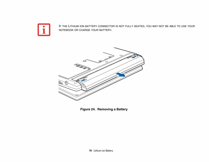
U MAY NOT BE ABLE TO USE YOUR
79 - Lithium ion Battery
Figure 24. Removing a Battery
IF THE LITHIUM ION BATTERY CONNECTOR IS NOT FULLY SEATED, YO
NOTEBOOK OR CHARGE YOUR BATTERY.
h speed Double Data Rate To increase your system’s grade must be a dual-in-line AM module only from the
r auto/airline).
e module compartment.
the same time. (Figure 26)
LE COMPARTMENT EXCEPT THE D REMOVING THE MEMORY
LECTROSTATIC DISCHARGE G PRECAUTIONS:
ETAL OBJECT TO DISCHARGE
BY THE EDGE SO AS NOT TO ANY INTERNAL COMPUTER ULD CAUSE A SHORT TO THE
REMOVING MEMORY MODULES. OULD BE LOST OR THE MEMORY EM.
80 - Memory Upgrade Module
Memory Upgrade ModuleYour Fujitsu LifeBook P1630 notebook comes with a minimum of 1GB of higSynchronous Dynamic RAM 2 (DDR2 SDRAM), 667 MHz factory installed.memory capacity, you may install a memory upgrade module. The memory up(DIMM) SDRAM module. To ensure 100% compatibility, purchase the SDRFujitsu web store at www.shopfujitsu.com.
Removing Memory Modules1 Turn off power to your LifeBook notebook and remove any power adapter (AC o
2 Make sure that all the connector covers are closed.
3 Turn the system bottom side up, and remove the screws of the memory upgrad(Figure 26).
4 Remove the cover.
5 Pull the clips sideways away from each side of the memory upgrade module at
• DO NOT REMOVE ANY SCREWS FROM THE MEMORY UPGRADE MODU
ONES SPECIFICALLY SHOWN IN THE DIRECTIONS FOR INSTALLING AN
UPGRADE MODULE.
• THE MEMORY UPGRADE MODULE CAN BE SEVERELY DAMAGED BY E(ESD). TO MINIMIZE RISK TO THE MODULE, OBSERVE THE FOLLOWIN
• BEFORE HANDLING A MEMORY MODULE, TOUCH A GROUNDED MSTATIC ELECTRICITY BUILT UP IN YOUR BODY.
• WHEN INSTALLING OR REMOVING A MEMORY MODULE, HOLD IT TOUCH ANY CONTACTS OR CHIPS. BE CAREFUL NOT TO TOUCH TERMINALS OR COMPONENTS; THE OIL FROM YOUR FINGERS CO
COMPONENTS.
• BE SURE TO POWER DOWN YOUR SYSTEM BEFORE ADDING OR EVEN IF THE SYSTEM IS IN HIBERNATE OR SLEEP STATES, DATA CCOULD BE DAMAGED IF POWER IS STILL AVAILABLE TO THE SYST
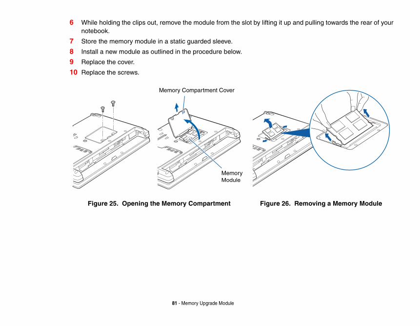
pulling towards the rear of your
oving a Memory Module
81 - Memory Upgrade Module
6 While holding the clips out, remove the module from the slot by lifting it up andnotebook.
7 Store the memory module in a static guarded sleeve.
8 Install a new module as outlined in the procedure below.
9 Replace the cover.
10 Replace the screws.
Figure 25. Opening the Memory Compartment Figure 26. Rem
Memory Compartment Cover
Memory Module
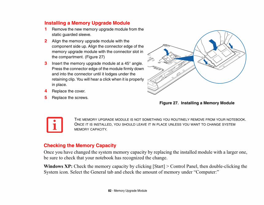
ed module with a larger one,
nel, then double-clicking the “Computer:”
ling a Memory Module
EMOVE FROM YOUR NOTEBOOK. ANT TO CHANGE SYSTEM
82 - Memory Upgrade Module
Checking the Memory CapacityOnce you have changed the system memory capacity by replacing the installbe sure to check that your notebook has recognized the change.
Windows XP: Check the memory capacity by clicking [Start] > Control PaSystem icon. Select the General tab and check the amount of memory under
Installing a Memory Upgrade Module1 Remove the new memory upgrade module from the
static guarded sleeve.
2 Align the memory upgrade module with the component side up. Align the connector edge of the memory upgrade module with the connector slot in the compartment. (Figure 27)
3 Insert the memory upgrade module at a 45° angle. Press the connector edge of the module firmly down and into the connector until it lodges under the retaining clip. You will hear a click when it is properly in place.
4 Replace the cover.
5 Replace the screws.Figure 27. Instal
THE MEMORY UPGRADE MODULE IS NOT SOMETHING YOU ROUTINELY RONCE IT IS INSTALLED, YOU SHOULD LEAVE IT IN PLACE UNLESS YOU WMEMORY CAPACITY.
by clicking [Start] > Control M and processor speed. The
tart] > Control Panel > System.
played. This is possible if your which dynamically allocates
R MEMORY UPGRADE MODULE IS D THE CAPACITY IS STILL NOT
83 - Memory Upgrade Module
Windows Vista:
• If you are in Control Panel Home view, check the memory capacityPanel > System and Maintenance > System > View amount of RAamount of memory is displayed next to “Memory - RAM:”
• If you are in Classic view, check the memory capacity by clicking [SThe amount of memory is displayed next to “Memory - RAM:”
There may be a variation between the actual memory size and what is dissystem is configured with an integrated Intel Graphics Media Acceleratorsystem memory to accelerate graphics performance.
IF THE TOTAL MEMORY DISPLAYED IS INCORRECT, CHECK THAT YOU
PROPERLY INSTALLED. (IF THE MODULE IS PROPERLY INSTALLED AN
CORRECTLY RECOGNIZED, SEE TROUBLESHOOTING ON PAGE 96.
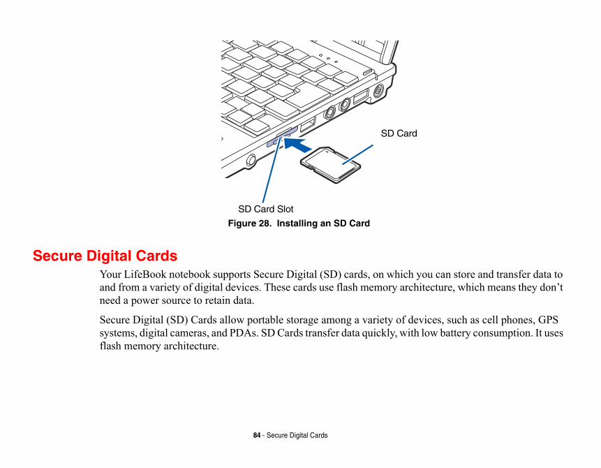
u can store and transfer data to ecture, which means they don’t
ces, such as cell phones, GPS w battery consumption. It uses
84 - Secure Digital Cards
Figure 28. Installing an SD Card
Secure Digital CardsYour LifeBook notebook supports Secure Digital (SD) cards, on which yoand from a variety of digital devices. These cards use flash memory architneed a power source to retain data.
Secure Digital (SD) Cards allow portable storage among a variety of devisystems, digital cameras, and PDAs. SD Cards transfer data quickly, with loflash memory architecture.
SD Card Slot
SD Card
rd, follow these steps:
e cards may require that your
SD Card.
me cards may require your rior to removing the card from ation area. To remove the card,
NOTEBOOK’S SHUTDOWN OR OK NOTEBOOK. OTHER SUBSTANCE ON THE CARD NOTEBOOK, OR BOTH.
85 - Secure Digital Cards
Inserting SD CardsSD Cards are inserted in the SD Card slot (Figure 28). To insert an SD Ca
1 See your SD Card manual for instructions on the insertion of your card. Somsystem is off while inserting them.
2 Make sure there is no card currently in the slot. If there is, see Removing an
3 Insert your card into the slot with the product label facing up.
4 Push the card firmly into the slot until it is seated in the connector.
Removing An SD CardTo remove an SD Card, first see your SD Card manual for instructions. SoLifeBook notebook to be in Suspend Mode or Off while removing them. Pthe slot, first select it using the Safely Remove Hardware icon in the notificpush it in to release it, then pull it out.
• INSERTING OR REMOVING AN SD CARD DURING YOUR LIFEBOOK
BOOTUP PROCESS MAY DAMAGE THE CARD AND/OR YOUR LIFEBO
• DO NOT INSERT A CARD INTO A SLOT IF THERE IS WATER OR ANY
AS YOU MAY PERMANENTLY DAMAGE THE CARD, YOUR LIFEBOOK
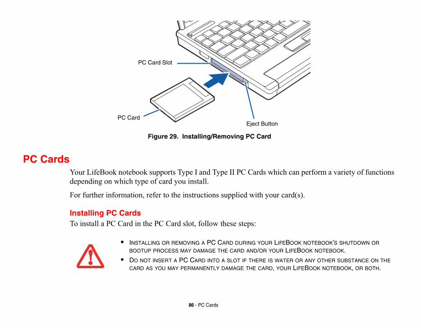
perform a variety of functions
).
K NOTEBOOK’S SHUTDOWN OR OOK NOTEBOOK.
R ANY OTHER SUBSTANCE ON THE FEBOOK NOTEBOOK, OR BOTH.
86 - PC Cards
Figure 29. Installing/Removing PC Card
PC CardsYour LifeBook notebook supports Type I and Type II PC Cards which candepending on which type of card you install.
For further information, refer to the instructions supplied with your card(s
Installing PC CardsTo install a PC Card in the PC Card slot, follow these steps:
Eject Button
PC Card Slot
PC Card
• INSTALLING OR REMOVING A PC CARD DURING YOUR LIFEBOO
BOOTUP PROCESS MAY DAMAGE THE CARD AND/OR YOUR LIFEB
• DO NOT INSERT A PC CARD INTO A SLOT IF THERE IS WATER OCARD AS YOU MAY PERMANENTLY DAMAGE THE CARD, YOUR LI
. Some PC Cards may require
C Cards.
ome cards may require your
utton will pop out.
e card slightly out of the slot
R OF THE ADMINISTRATOR’S TED TO A NETWORK, NETWORK OCEDURE.
T BE FOLLOWED BEFORE THE CORRECT PROCEDURE.) IT HARDWARE ICON IN THE SYSTEM
YOU MUST SAVE ALL OF YOUR NOTEBOOK.
PULL THE CABLE WHEN
87 - PC Cards
1 See your PC Card manual for specific instructions on the insertion of your cardyour notebook to be Off while inserting them.
2 Make sure there is no PC Card currently in the slot. If there is, see Removing P
3 Insert your PC Card into the slot, with the product label facing up.
4 Push the card into the slot firmly until it is seated in the opening.
Removing PC CardsSee your PC Card manual for specific instructions on removing your card. Snotebook to be in Sleep Mode or Off during removal.
1 Unlock the card from the slot by pressing the eject button. When pressed, the b
2 Firmly press the button again until it is flush with the notebook. This will eject thallowing you to remove the card.
YOU MAY BE REQUIRED TO LOG ON AS AN ADMINISTRATOR OR MEMBE
GROUP TO COMPLETE THIS PROCEDURE. IF THE COMPUTER IS CONNEC
POLICY SETTINGS MAY ALSO PREVENT YOU FROM COMPLETING THIS PR
• WINDOWS HAS A SHUTDOWN PROCEDURE FOR PC CARDS THAT MUS
REMOVING A CARD. (REVIEW YOUR OPERATING SYSTEM MANUAL FOR
IS GOOD PRACTICE TO REMOVE DEVICES USING THE SAFELY REMOVE TRAY.
• IF THE DIALOG BOX STATES THAT THE DEVICE CANNOT BE REMOVED,OPEN FILES, CLOSE ANY OPEN APPLICATIONS AND SHUT DOWN YOUR
IF THE PC CARD HAS AN EXTERNAL CONNECTOR AND CABLE, DO NOT
REMOVING THE CARD.
ds are the same size and shape can hold a variety of different g you to make secure
sonal identification and
tional Smart Card adapter and
88 - PC Cards
Smart Card ReaderAn embedded Smart Card Reader is provided on your notebook. Smart Caras credit cards, but they contain an integrated microprocessor chip. The chipinformation, and provides you with many possible options, such as allowinpurchases, pay for phone calls, store security information, and provide perinformation.
In order to use the embedded Smart Card Reader, you must purchase an opthird-party software for installation into an available Type II PC Card slot.
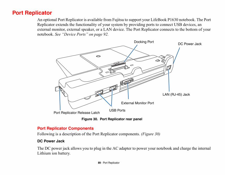
k P1630 notebook. The Port nnect USB devices, an nnects to the bottom of your
book and charge the internal
DC Power Jack
AN (RJ-45) Jack
89 - Port Replicator
Port ReplicatorAn optional Port Replicator is available from Fujitsu to support your LifeBooReplicator extends the functionality of your system by providing ports to coexternal monitor, external speaker, or a LAN device. The Port Replicator conotebook. See “Device Ports” on page 92.
Figure 30. Port Replicator rear panel
Port Replicator ComponentsFollowing is a description of the Port Replicator components. (Figure 30)
DC Power Jack
The DC power jack allows you to plug in the AC adapter to power your noteLithium ion battery.
Docking Port
L
External Monitor Port
USB PortsPort Replicator Release Latch
B 2.0 ports are backward-
monitor. Note that if a Port licator, not the one on your
when the system is attached ot the one on the system.
ve the Port Replicator from
ED BY ELECTROSTATIC THE FOLLOWING PRECAUTIONS:
HEN USING A PORT UNDED METAL OBJECT TO
MOVING SYSTEM STATES, DATA COULD BE LOST O THE SYSTEM.
90 - Port Replicator
USB 2.0 Ports (Qty. 2)
Universal Serial Bus (USB) 2.0 ports allow you to connect USB devices. UScompatible with USB 1.1 devices.
External Monitor Port
The external monitor port allows you to connect an external VGA or SVGAReplicator is attached, you must use the external monitor port on the Port Repsystem.
LAN (RJ-45) Jack
The LAN jack allows you to connect a LAN to the Port Replicator. Note that to the Port Replicator, the LAN Jack on the Port Replicator should be used, n
Docking Port
The docking port connects the Port Replicator to your LifeBook notebook.
Port Replicator Release Latch
Pull the Port Replicator Release latch away from the Port Replicator to remoyour notebook.
• THE SYSTEM CONTAINS COMPONENTS THAT CAN BE SEVERELY DAMAG
DISCHARGE (ESD). TO MINIMIZE RISK TO THE COMPONENTS, OBSERVE
- BEFORE DOCKING OR UNDOCKING YOUR LIFEBOOK NOTEBOOK (WREPLICATOR), IT IS A GOOD PRACTICE TO ALWAYS TOUCH A GRO
DISCHARGE STATIC ELECTRICITY BUILT UP IN YOUR BODY.
- BE SURE TO POWER DOWN YOUR SYSTEM BEFORE ADDING OR RE
COMPONENTS. EVEN IF THE SYSTEM IS IN HIBERNATE OR SLEEP OR MEMORY COULD BE DAMAGED IF POWER IS STILL AVAILABLE T
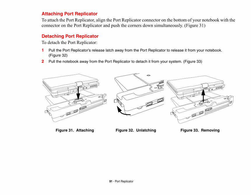
ttom of your notebook with the ly. (Figure 31)
se it from your notebook.
m. (Figure 33)
Figure 33. Removing
91 - Port Replicator
Attaching Port ReplicatorTo attach the Port Replicator, align the Port Replicator connector on the boconnector on the Port Replicator and push the corners down simultaneous
Detaching Port ReplicatorTo detach the Port Replicator:
1 Pull the Port Replicator’s release latch away from the Port Replicator to relea(Figure 32)
2 Pull the notebook away from the Port Replicator to detach it from your syste
Figure 31. Attaching Figure 32. Unlatching
pped with multiple Device yboards, modems, printers,
hone cable follow these easy
YSTEMS. DO NOT CONNECT THE GE TO THE INTERNAL MODEM OR NUFACTURER’S DOCUMENTATION TO FIND OUT BEFORE YOU
ITS MAXIMUM SPEED OF 53000 ION RATE DEPENDS ON THE LINE
M FUJITSU COMPUTER SYSTEMS ND CANADA.
92 - Device Ports
Device PortsYour LifeBook P1630 notebook and the optional Port Replicator come equiPorts to which you can connect an external device including: disk drives, keetc.
Modem (RJ-11) JackThe modem (RJ-11) jack is used for an internal modem. To connect the telepsteps: (Figure 5)
1 Align the connector with the jack opening.
2 Push the connector into the jack until it is seated.
3 Plug the other end of the telephone cable into a telephone outlet.
THE INTERNAL MODEM IS NOT INTENDED FOR USE WITH DIGITAL PBX SINTERNAL MODEM TO A DIGITAL PBX AS IT MAY CAUSE SERIOUS DAMA
YOUR ENTIRE LIFEBOOK P1630 NOTEBOOK. CONSULT YOUR PBX MA
FOR DETAILS. SOME HOTELS HAVE DIGITAL PBX SYSTEMS. BE SURE CONNECT YOUR MODEM.
• THE INTERNAL MODEM IS DESIGNED TO THE ITU V.90 STANDARD.BPS IS THE HIGHEST ALLOWED BY FCC, AND ITS ACTUAL CONNECT
CONDITIONS. THE MAXIMUM SPEED IS 33600 BPS AT UPLOAD.
• THE INTERNAL MODEM ON ALL LIFEBOOK P1630 NOTEBOOK’S FRO
CORPORATION ARE CERTIFIED FOR USE IN THE UNITED STATES A
hernet connection. You will se refer to your network e LAN cable follow these
rt replicator. In order to e with your port replicator.
ices such as external floppy d/or speakers. USB 2.0 is k with these ports. USB 2.0
HE LAN JACK LOCATED ON THE EPLICATOR IS THE ONLY ONE
93 - Device Ports
Internal LAN (RJ-45) jack The internal LAN (RJ-45) jack is used for an internal 10/100/1000 BaseTx Etneed to configure your notebook to work with your particular network. (Pleaadministrator for information on your network configuration.) To connect theasy steps: (Figure 5)
1 Align the connector with the jack opening.
2 Push the connector into the jack until it is seated.
3 Plug the other end of the cable into a LAN outlet.
Docking PortThe docking port is used for the connection of your system to an optional poconnect your system to one of these devices follow the instructions that cam(Figure 6)
Universal Serial Bus PortsThe two Universal Serial Bus 2.0 ports (USB) allow you to connect USB devdisk drives, external DVD drives, game pads, pointing devices, keyboards andownward-compatible with USB 1.1 devices, so older USB devices will woris a much faster design, running forty times faster than USB 1.1.
In order to connect a USB device, follow these easy steps: (Figure 5)1 Align the connector with the port opening.
2 Push the connector into the port until it is seated.
NOTE THAT THE OPTIONAL PORT REPLICATOR IS DESIGNED TO COVER TSYSTEM. THIS DESIGN ENSURES THAT THE LAN JACK ON THE PORT RUSED WHEN THE PORT REPLICATOR IS INSTALLED.
Your microphone must be hone jack of your notebook.
speakers to your notebook. ini-plug. In order to connect
rojector. In order to connect al VGA monitor on the port
STEREO SPEAKERS WILL BE
94 - Device Ports
Microphone JackThe microphone jack allows you to connect an external mono microphone. equipped with a 1/8”(3.5 mm) mono mini-plug in order to fit into the micropIn order to connect a microphone follow these easy steps: (Figure 4)1 Align the connector with the port opening.
2 Push the connector into the port until it is seated.
Headphone JackThe headphone jack allows you to connect headphones or powered externalYour headphones or speakers must be equipped with a 1/8” (3.5 mm) stereo mheadphones or speakers follow these easy steps: (Figure 4)
1 Align the connector with the port opening.
2 Push the connector into the port until it is seated.
External Video PortThe external video port allows you to connect an external monitor or LCD pan external device follow these easy steps: (Figure 5). There is also an externreplicator (Figure 30). 1 Remove the cover from the port opening, if present.
2 Align the connector with the port opening.
3 Push the connector into the port until it is seated.
4 Tighten the two hold-down screws, located on each side of the connector.
IF YOU PLUG HEADPHONES INTO THE HEADPHONE JACK, THE BUILT-IN DISABLED.
+ [F10] KEYS ALLOWS YOU TO O. EACH TIME YOU PRESS THE KEY H THE BUILT-IN DISPLAY PANEL TO BOTH THE BUILT-IN DISPLAY
OOK APPLICATION PANEL N) ALSO ALLOWS YOU TO CHANGE
95 - Device Ports
WHEN AN EXTERNAL MONITOR IS PLUGGED IN, PRESSING THE [FN] CHANGE YOUR SELECTION OF WHERE TO SEND YOUR DISPLAY VIDE
COMBINATION, YOU WILL STEP TO THE NEXT CHOICE, STARTING WIT
ONLY, MOVING TO THE EXTERNAL MONITOR ONLY, FINALLY MOVING PANEL AND AN EXTERNAL MONITOR.
WHEN AN EXTERNAL MONITOR IS PLUGGED IN, PRESSING THE LIFEBSECONDARY FUNCTION BUTTONS (FN + SCREEN ROTATION BUTTO
YOUR SELECTION OF WHERE TO SEND YOUR DISPLAY VIDEO.
Trouboblems that you can solve on cing the device. The raightforward issues and
ursuing complex
ower source.
also remove the card from the
n properly. You can also
u turn it back on.
96
Chapter 4
Troubleshooting Your LifeBook
leshootingThere may be occasions when you encounter simple setup or operating prthe spot, or problems with peripheral devices that can be solved by replainformation in this section helps you isolate and resolve some of these stidentify failures that require service.
Identifying the ProblemIf you encounter a problem, go through the following procedure before ptroubleshooting:
1 Turn off your LifeBook notebook.
2 Make sure the AC adapter is plugged into your notebook and to an active AC p
3 Make sure that any card installed in the PC Card slot is seated properly. You canslot, thus eliminating it as a possible cause of failure.
4 Make sure that any devices connected to the external connectors are plugged idisconnect such devices, thus eliminating them as possible causes of failure.
5 Turn on your notebook. Make sure it has been off at least 10 seconds before yo
6 Go through the boot sequence.
t follows, for more detailed
t success, contact your support
dy so that the customer support
guration and serial numbers.
PRESENTATIVE MAY BE ABLE TO HELP HONE.
HAVE TALKED TO A SUPPORT
97 - Troubleshooting Your LifeBook
7 If the problem has not been resolved, refer to the Troubleshooting Table, thatroubleshooting information.
8 If you have tried the solutions suggested in the Troubleshooting Table withourepresentative:
Toll free: 1-800-8Fujitsu (1-800-838-5487) E-mail: [email protected] Web site: http://www.computers.us.fujitsu.com/support.
Before you place the call, you should have the following information rearepresentative can provide you with the fastest possible solution:
• Product name• Product configuration number• Product serial number• Purchase date• Conditions under which the problem occurred• Any error messages that have occurred• Type of device connected, if anySee the Configuration Label on the bottom of your notebook for confi
• IF YOU KEEP NOTES ABOUT WHAT YOU HAVE TRIED, YOUR SUPPORT RE
YOU MORE QUICKLY BY GIVING ADDITIONAL SUGGESTIONS OVER THE P
• DO NOT RETURN A FAILED NOTEBOOK TO YOUR SUPPLIER UNTIL YOU REPRESENTATIVE.
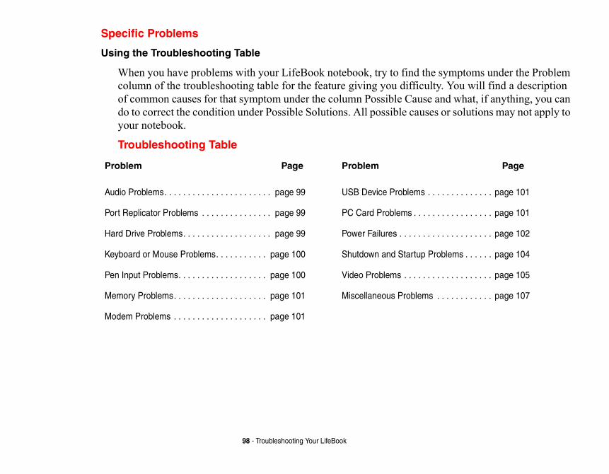
symptoms under the Problem ty. You will find a description and what, if anything, you can s or solutions may not apply to
Page
. . . . . . . . . . . . . page 101
. . . . . . . . . . . . . page 101
. . . . . . . . . . . . . page 102
roblems . . . . . . page 104
. . . . . . . . . . . . . page 105
. . . . . . . . . . . . page 107
98 - Troubleshooting Your LifeBook
Specific Problems
Using the Troubleshooting Table
When you have problems with your LifeBook notebook, try to find thecolumn of the troubleshooting table for the feature giving you difficulof common causes for that symptom under the column Possible Causedo to correct the condition under Possible Solutions. All possible causeyour notebook.
Troubleshooting Table
Problem Page
Audio Problems. . . . . . . . . . . . . . . . . . . . . . . page 99
Port Replicator Problems . . . . . . . . . . . . . . . page 99
Hard Drive Problems. . . . . . . . . . . . . . . . . . . page 99
Keyboard or Mouse Problems. . . . . . . . . . . page 100
Pen Input Problems. . . . . . . . . . . . . . . . . . . page 100
Memory Problems. . . . . . . . . . . . . . . . . . . . page 101
Modem Problems . . . . . . . . . . . . . . . . . . . . page 101
Problem
USB Device Problems .
PC Card Problems . . . .
Power Failures . . . . . . .
Shutdown and Startup P
Video Problems . . . . . .
Miscellaneous Problems
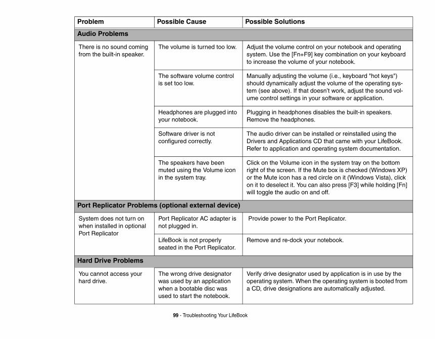
on your notebook and operating key combination on your keyboard your notebook.
lume (i.e., keyboard "hot keys") the volume of the operating sys-esn’t work, adjust the sound vol-
ur software or application.
isables the built-in speakers.
stalled or reinstalled using the D that came with your LifeBook.
perating system documentation.
in the system tray on the bottom ute box is checked (Windows XP) circle on it (Windows Vista), click
n also press [F3] while holding [Fn] d off.
t Replicator.
notebook.
ed by application is in use by the he operating system is booted from re automatically adjusted.
99 - Troubleshooting Your LifeBook
Problem Possible Cause Possible Solutions
Audio Problems
There is no sound coming from the built-in speaker.
The volume is turned too low. Adjust the volume controlsystem. Use the [Fn+F9] to increase the volume of
The software volume control is set too low.
Manually adjusting the voshould dynamically adjusttem (see above). If that doume control settings in yo
Headphones are plugged into your notebook.
Plugging in headphones dRemove the headphones.
Software driver is not configured correctly.
The audio driver can be inDrivers and Applications CRefer to application and o
The speakers have been muted using the Volume icon in the system tray.
Click on the Volume icon right of the screen. If the Mor the Mute icon has a redon it to deselect it. You cawill toggle the audio on an
Port Replicator Problems (optional external device)
System does not turn on when installed in optional Port Replicator
Port Replicator AC adapter is not plugged in.
Provide power to the Por
LifeBook is not properly seated in the Port Replicator.
Remove and re-dock your
Hard Drive Problems
You cannot access your hard drive.
The wrong drive designator was used by an application when a bootable disc was used to start the notebook.
Verify drive designator usoperating system. When ta CD, drive designations a
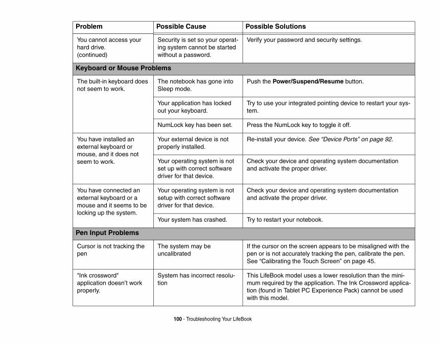
curity settings.
esume button.
ointing device to restart your sys-
oggle it off.
“Device Ports” on page 92.
rating system documentation er.
rating system documentation er.
.
ppears to be misaligned with the king the pen, calibrate the pen. Screen” on page 45.
lower resolution than the mini-ation. The Ink Crossword applica-erience Pack) cannot be used
100 - Troubleshooting Your LifeBook
You cannot access your hard drive. (continued)
Security is set so your operat-ing system cannot be started without a password.
Verify your password and se
Keyboard or Mouse Problems
The built-in keyboard does not seem to work.
The notebook has gone into Sleep mode.
Push the Power/Suspend/R
Your application has locked out your keyboard.
Try to use your integrated ptem.
NumLock key has been set. Press the NumLock key to t
You have installed an external keyboard or mouse, and it does not seem to work.
Your external device is not properly installed.
Re-install your device. See
Your operating system is not set up with correct software driver for that device.
Check your device and opeand activate the proper driv
You have connected an external keyboard or a mouse and it seems to be locking up the system.
Your operating system is not setup with correct software driver for that device.
Check your device and opeand activate the proper driv
Your system has crashed. Try to restart your notebook
Pen Input Problems
Cursor is not tracking the pen
The system may be uncalibrated
If the cursor on the screen apen or is not accurately tracSee “Calibrating the Touch
"Ink crossword" application doesn’t work properly.
System has incorrect resolu-tion
This LifeBook model uses amum required by the appliction (found in Tablet PC Expwith this model.
Problem Possible Cause Possible Solutions
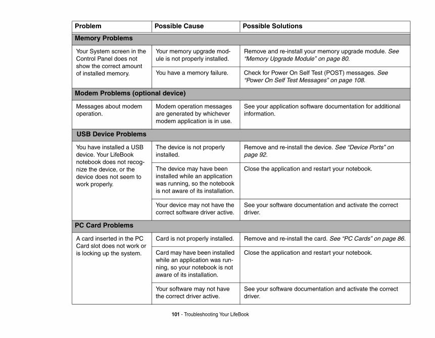
memory upgrade module. See on page 80.
st (POST) messages. See ges” on page 108.
re documentation for additional
evice. See “Device Ports” on
estart your notebook.
ntation and activate the correct
ard. See “PC Cards” on page 86.
estart your notebook.
ntation and activate the correct
101 - Troubleshooting Your LifeBook
Memory Problems
Your System screen in the Control Panel does not show the correct amount of installed memory.
Your memory upgrade mod-ule is not properly installed.
Remove and re-install your“Memory Upgrade Module”
You have a memory failure. Check for Power On Self Te“Power On Self Test Messa
Modem Problems (optional device)
Messages about modem operation.
Modem operation messages are generated by whichever modem application is in use.
See your application softwainformation.
USB Device Problems
You have installed a USB device. Your LifeBook notebook does not recog-nize the device, or the device does not seem to work properly.
The device is not properly installed.
Remove and re-install the dpage 92.
The device may have been installed while an application was running, so the notebook is not aware of its installation.
Close the application and r
Your device may not have the correct software driver active.
See your software documedriver.
PC Card Problems
A card inserted in the PC Card slot does not work or is locking up the system.
Card is not properly installed. Remove and re-install the c
Card may have been installed while an application was run-ning, so your notebook is not aware of its installation.
Close the application and r
Your software may not have the correct driver active.
See your software documedriver.
Problem Possible Cause Possible Solutions
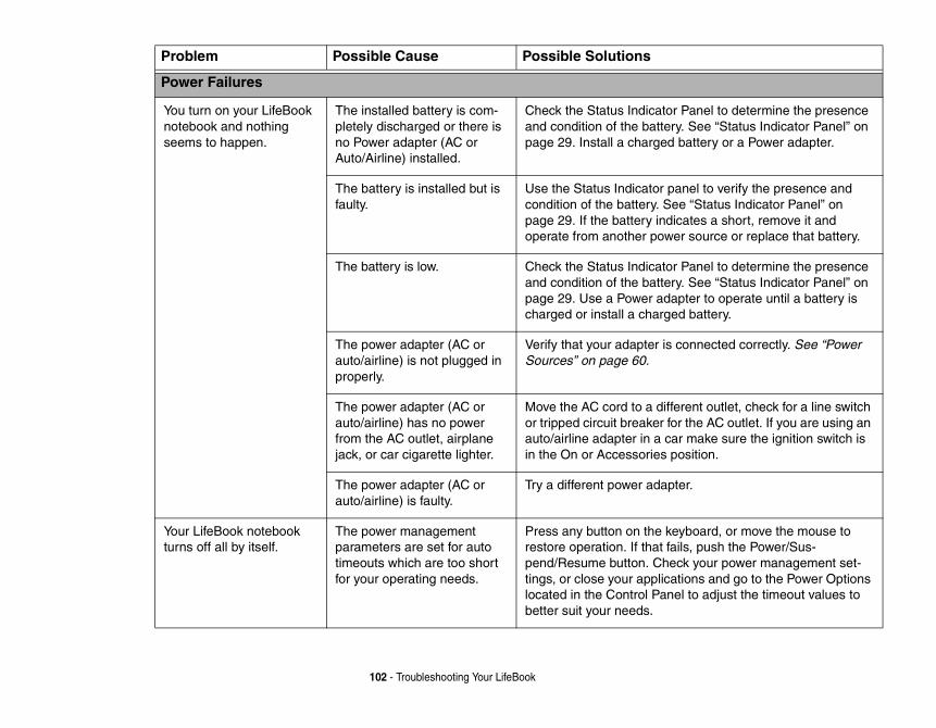
Panel to determine the presence . See “Status Indicator Panel” on attery or a Power adapter.
nel to verify the presence and “Status Indicator Panel” on
ates a short, remove it and r source or replace that battery.
Panel to determine the presence . See “Status Indicator Panel” on ter to operate until a battery is battery.
onnected correctly. See “Power
rent outlet, check for a line switch the AC outlet. If you are using an make sure the ignition switch is sition.
r.
board, or move the mouse to ls, push the Power/Sus-k your power management set-ions and go to the Power Options l to adjust the timeout values to
102 - Troubleshooting Your LifeBook
Power Failures
You turn on your LifeBook notebook and nothing seems to happen.
The installed battery is com-pletely discharged or there is no Power adapter (AC or Auto/Airline) installed.
Check the Status Indicator and condition of the batterypage 29. Install a charged b
The battery is installed but is faulty.
Use the Status Indicator pacondition of the battery. Seepage 29. If the battery indicoperate from another powe
The battery is low. Check the Status Indicator and condition of the batterypage 29. Use a Power adapcharged or install a charged
The power adapter (AC or auto/airline) is not plugged in properly.
Verify that your adapter is cSources” on page 60.
The power adapter (AC or auto/airline) has no power from the AC outlet, airplane jack, or car cigarette lighter.
Move the AC cord to a diffeor tripped circuit breaker forauto/airline adapter in a carin the On or Accessories po
The power adapter (AC or auto/airline) is faulty.
Try a different power adapte
Your LifeBook notebook turns off all by itself.
The power management parameters are set for auto timeouts which are too short for your operating needs.
Press any button on the keyrestore operation. If that faipend/Resume button. Chectings, or close your applicatlocated in the Control Panebetter suit your needs.
Problem Possible Cause Possible Solutions
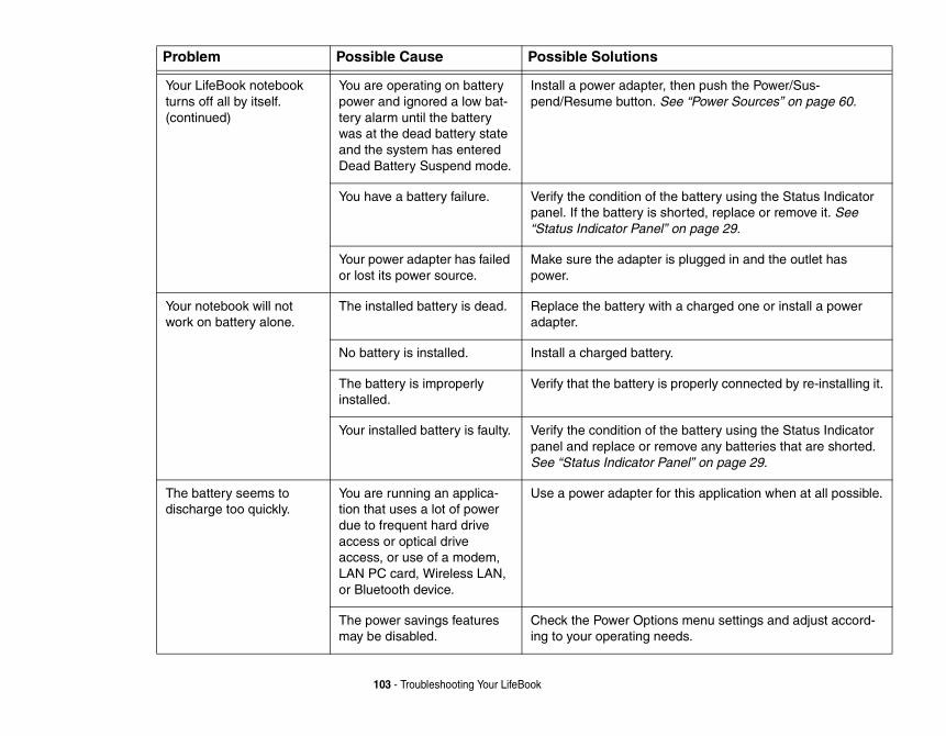
push the Power/Sus-Power Sources” on page 60.
attery using the Status Indicator ed, replace or remove it. See page 29.
ugged in and the outlet has
harged one or install a power
perly connected by re-installing it.
attery using the Status Indicator e any batteries that are shorted. ” on page 29.
s application when at all possible.
enu settings and adjust accord-.
103 - Troubleshooting Your LifeBook
Your LifeBook notebook turns off all by itself. (continued)
You are operating on battery power and ignored a low bat-tery alarm until the battery was at the dead battery state and the system has entered Dead Battery Suspend mode.
Install a power adapter, thenpend/Resume button. See “
You have a battery failure. Verify the condition of the bpanel. If the battery is short“Status Indicator Panel” on
Your power adapter has failed or lost its power source.
Make sure the adapter is plpower.
Your notebook will not work on battery alone.
The installed battery is dead. Replace the battery with a cadapter.
No battery is installed. Install a charged battery.
The battery is improperly installed.
Verify that the battery is pro
Your installed battery is faulty. Verify the condition of the bpanel and replace or removSee “Status Indicator Panel
The battery seems to discharge too quickly.
You are running an applica-tion that uses a lot of power due to frequent hard drive access or optical drive access, or use of a modem, LAN PC card, Wireless LAN, or Bluetooth device.
Use a power adapter for thi
The power savings features may be disabled.
Check the Power Options ming to your operating needs
Problem Possible Cause Possible Solutions
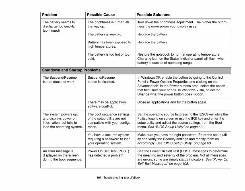
djustment. The higher the bright-display uses.
rmal operating temperature. s Indicator panel will flash when ing range.
button by going to the Control perties and clicking on the r buttons area, select the option In Windows Vista, select the tton does” option.
ry the button again.
pressing the [ESC] key while the use the [F2] key and enter the source settings from the Boot tility” on page 63.
ht password. Enter the setup util-ettings and modify them as tup Utility” on page 63.
t (POST) messages to determine f the problem. Not all messages status indicators. See “Power On ge 108.
104 - Troubleshooting Your LifeBook
The battery seems to discharge too quickly. (continued)
The brightness is turned all the way up.
Turn down the brightness aness the more power your
The battery is very old. Replace the battery.
Battery has been exposed to high temperatures.
Replace the battery.
The battery is too hot or too cold.
Restore the notebook to noCharging icon on the Statubattery is outside of operat
Shutdown and Startup Problems
The Suspend/Resume button does not work.
Suspend/Resume button is disabled.
In Windows XP, enable thePanel > Power Options ProAdvanced tab. In the Powethat best suits your needs. Change what the power bu
There may be application software conflict.
Close all applications and t
The system powers up, and displays power on information, but fails to load the operating system.
The boot sequence settings of the setup utility are not compatible with your configu-ration.
Set the operating source byFujitsu logo is on screen orsetup utility and adjust the menu. See “BIOS Setup U
You have a secured system requiring a password to load your operating system.
Make sure you have the rigity and verify the Security saccordingly. See “BIOS Se
An error message is displayed on the screen during the boot sequence.
Power On Self Test (POST) has detected a problem.
See the Power On Self Testhe meaning and severity oare errors; some are simplySelf Test Messages” on pa
Problem Possible Cause Possible Solutions
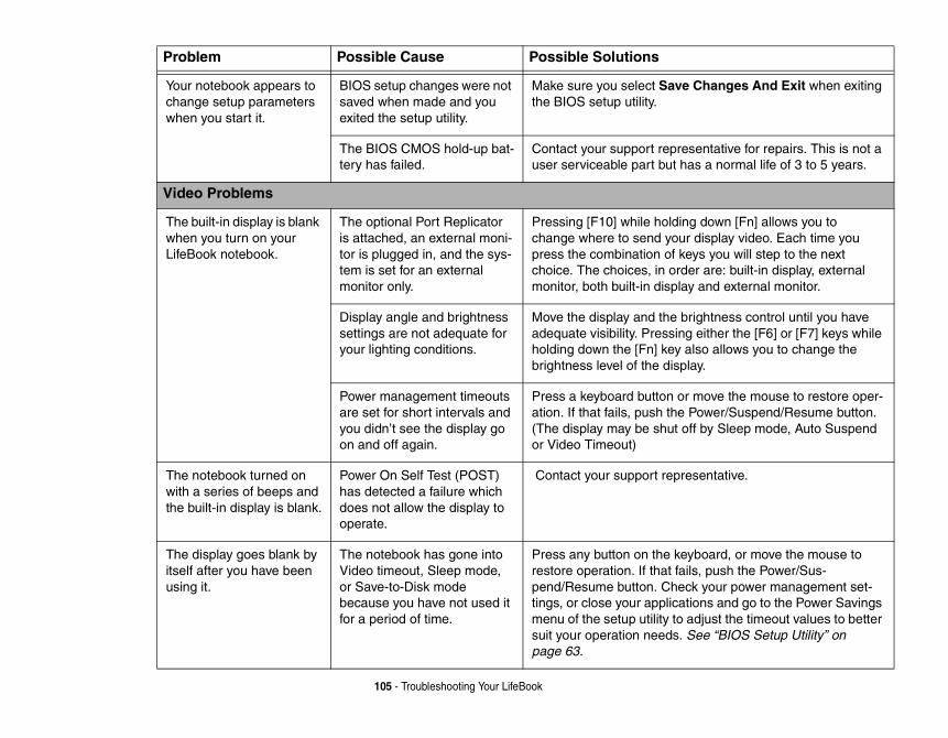
Changes And Exit when exiting
entative for repairs. This is not a s a normal life of 3 to 5 years.
down [Fn] allows you to display video. Each time you ys you will step to the next r are: built-in display, external and external monitor.
ightness control until you have either the [F6] or [F7] keys while lso allows you to change the y.
move the mouse to restore oper-ower/Suspend/Resume button.
f by Sleep mode, Auto Suspend
sentative.
board, or move the mouse to s, push the Power/Sus-k your power management set-ons and go to the Power Savings djust the timeout values to better ee “BIOS Setup Utility” on
105 - Troubleshooting Your LifeBook
Your notebook appears to change setup parameters when you start it.
BIOS setup changes were not saved when made and you exited the setup utility.
Make sure you select Save the BIOS setup utility.
The BIOS CMOS hold-up bat-tery has failed.
Contact your support represuser serviceable part but ha
Video Problems
The built-in display is blank when you turn on your LifeBook notebook.
The optional Port Replicator is attached, an external moni-tor is plugged in, and the sys-tem is set for an external monitor only.
Pressing [F10] while holdingchange where to send your press the combination of kechoice. The choices, in ordemonitor, both built-in display
Display angle and brightness settings are not adequate for your lighting conditions.
Move the display and the bradequate visibility. Pressingholding down the [Fn] key abrightness level of the displa
Power management timeouts are set for short intervals and you didn’t see the display go on and off again.
Press a keyboard button or ation. If that fails, push the P(The display may be shut ofor Video Timeout)
The notebook turned on with a series of beeps and the built-in display is blank.
Power On Self Test (POST) has detected a failure which does not allow the display to operate.
Contact your support repre
The display goes blank by itself after you have been using it.
The notebook has gone into Video timeout, Sleep mode, or Save-to-Disk mode because you have not used it for a period of time.
Press any button on the keyrestore operation. If that failpend/Resume button. Chectings, or close your applicatimenu of the setup utility to asuit your operation needs. Spage 63.
Problem Possible Cause Possible Solutions
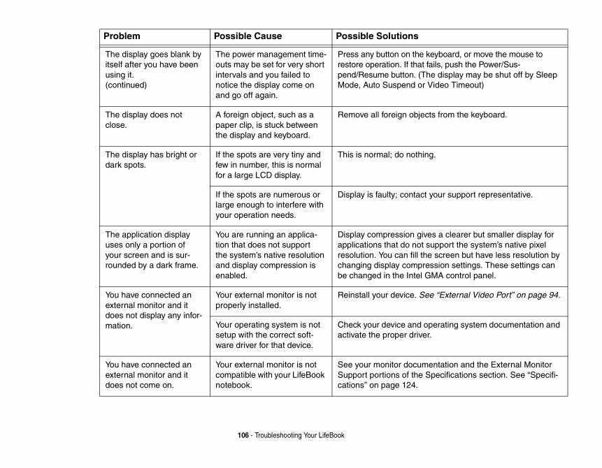
e keyboard, or move the mouse to t fails, push the Power/Sus-
(The display may be shut off by Sleep or Video Timeout)
jects from the keyboard.
hing.
ct your support representative.
ives a clearer but smaller display for t support the system’s native pixel
the screen but have less resolution by pression settings. These settings can l GMA control panel.
See “External Video Port” on page 94.
operating system documentation and ver.
mentation and the External Monitor e Specifications section. See “Specifi-
106 - Troubleshooting Your LifeBook
The display goes blank by itself after you have been using it. (continued)
The power management time-outs may be set for very short intervals and you failed to notice the display come on and go off again.
Press any button on threstore operation. If thapend/Resume button. Mode, Auto Suspend
The display does not close.
A foreign object, such as a paper clip, is stuck between the display and keyboard.
Remove all foreign ob
The display has bright or dark spots.
If the spots are very tiny and few in number, this is normal for a large LCD display.
This is normal; do not
If the spots are numerous or large enough to interfere with your operation needs.
Display is faulty; conta
The application display uses only a portion of your screen and is sur-rounded by a dark frame.
You are running an applica-tion that does not support the system’s native resolution and display compression is enabled.
Display compression gapplications that do noresolution. You can fillchanging display combe changed in the Inte
You have connected an external monitor and it does not display any infor-mation.
Your external monitor is not properly installed.
Reinstall your device.
Your operating system is not setup with the correct soft-ware driver for that device.
Check your device andactivate the proper dri
You have connected an external monitor and it does not come on.
Your external monitor is not compatible with your LifeBook notebook.
See your monitor docuSupport portions of thcations” on page 124.
Problem Possible Cause Possible Solutions
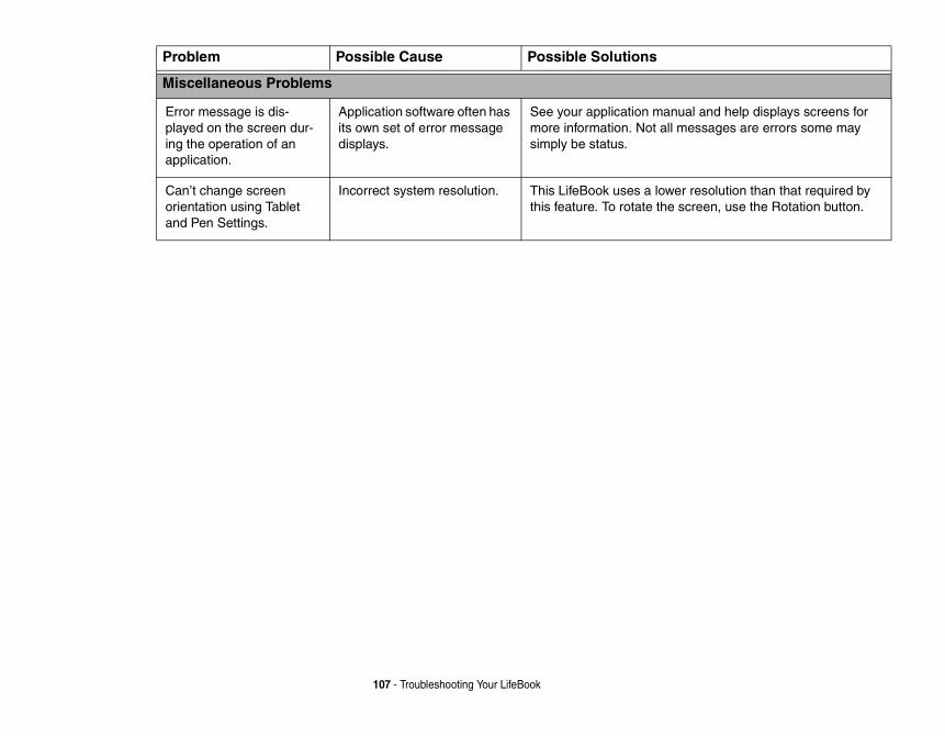
nual and help displays screens for ll messages are errors some may
er resolution than that required by e screen, use the Rotation button.
107 - Troubleshooting Your LifeBook
Miscellaneous Problems
Error message is dis-played on the screen dur-ing the operation of an application.
Application software often has its own set of error message displays.
See your application mamore information. Not asimply be status.
Can’t change screen orientation using Tablet and Pen Settings.
Incorrect system resolution. This LifeBook uses a lowthis feature. To rotate th
Problem Possible Cause Possible Solutions
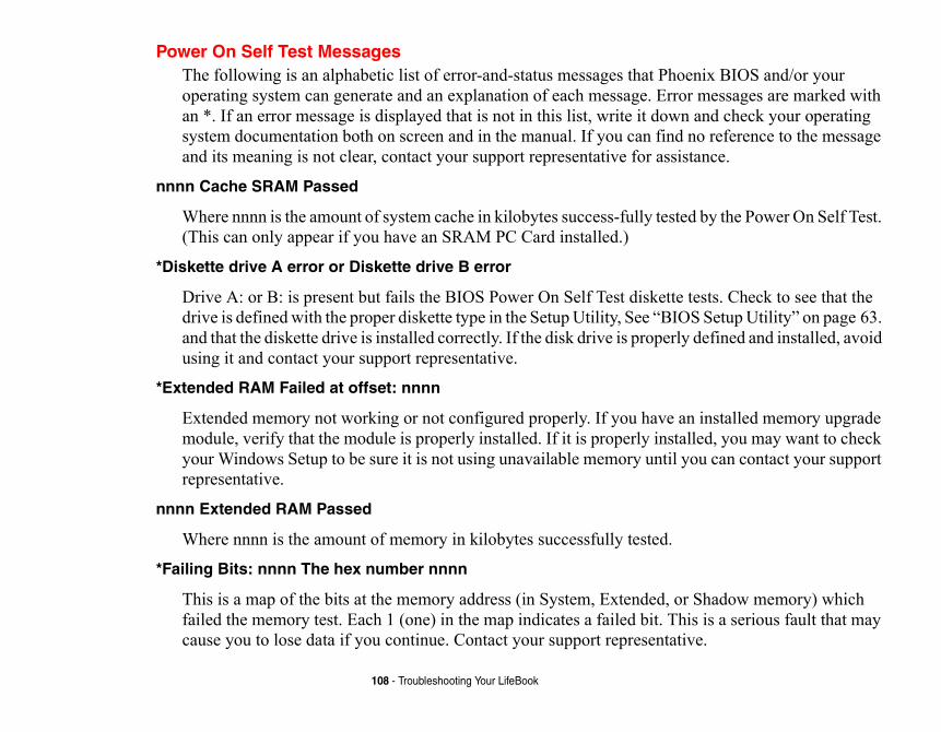
enix BIOS and/or your r messages are marked with and check your operating no reference to the message tance.
d by the Power On Self Test.
tests. Check to see that the S Setup Utility” on page 63. defined and installed, avoid
n installed memory upgrade lled, you may want to check ou can contact your support
Shadow memory) which is is a serious fault that may ve.
108 - Troubleshooting Your LifeBook
Power On Self Test MessagesThe following is an alphabetic list of error-and-status messages that Phooperating system can generate and an explanation of each message. Erroan *. If an error message is displayed that is not in this list, write it downsystem documentation both on screen and in the manual. If you can find and its meaning is not clear, contact your support representative for assis
nnnn Cache SRAM Passed
Where nnnn is the amount of system cache in kilobytes success-fully teste(This can only appear if you have an SRAM PC Card installed.)
*Diskette drive A error or Diskette drive B error
Drive A: or B: is present but fails the BIOS Power On Self Test diskette drive is defined with the proper diskette type in the Setup Utility, See “BIOand that the diskette drive is installed correctly. If the disk drive is properlyusing it and contact your support representative.
*Extended RAM Failed at offset: nnnn
Extended memory not working or not configured properly. If you have amodule, verify that the module is properly installed. If it is properly instayour Windows Setup to be sure it is not using unavailable memory until yrepresentative.
nnnn Extended RAM Passed
Where nnnn is the amount of memory in kilobytes successfully tested.
*Failing Bits: nnnn The hex number nnnn
This is a map of the bits at the memory address (in System, Extended, orfailed the memory test. Each 1 (one) in the map indicates a failed bit. Thcause you to lose data if you continue. Contact your support representati
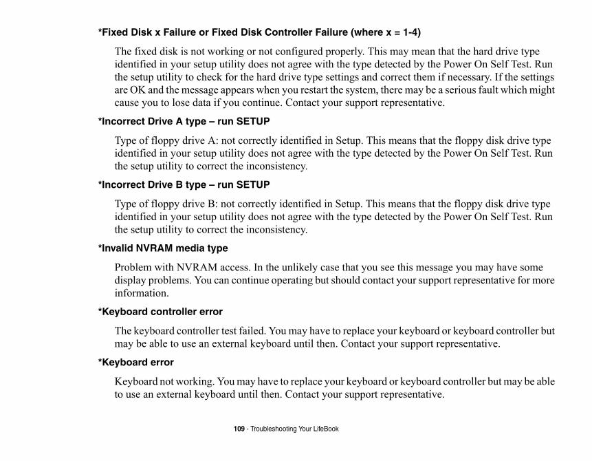
ean that the hard drive type y the Power On Self Test. Run em if necessary. If the settings be a serious fault which might ative.
that the floppy disk drive type y the Power On Self Test. Run
hat the floppy disk drive type y the Power On Self Test. Run
essage you may have some upport representative for more
oard or keyboard controller but ort representative.
oard controller but may be able ative.
109 - Troubleshooting Your LifeBook
*Fixed Disk x Failure or Fixed Disk Controller Failure (where x = 1-4)
The fixed disk is not working or not configured properly. This may midentified in your setup utility does not agree with the type detected bthe setup utility to check for the hard drive type settings and correct thare OK and the message appears when you restart the system, there maycause you to lose data if you continue. Contact your support represent
*Incorrect Drive A type – run SETUP
Type of floppy drive A: not correctly identified in Setup. This means identified in your setup utility does not agree with the type detected bthe setup utility to correct the inconsistency.
*Incorrect Drive B type – run SETUP
Type of floppy drive B: not correctly identified in Setup. This means tidentified in your setup utility does not agree with the type detected bthe setup utility to correct the inconsistency.
*Invalid NVRAM media type
Problem with NVRAM access. In the unlikely case that you see this mdisplay problems. You can continue operating but should contact your sinformation.
*Keyboard controller error
The keyboard controller test failed. You may have to replace your keybmay be able to use an external keyboard until then. Contact your supp
*Keyboard error
Keyboard not working. You may have to replace your keyboard or keybto use an external keyboard until then. Contact your support represent
ey. You may have to replace ontact your support
s your BIOS is corrupted, run get this error, contact your
he setup utility and see if both uence is set correctly. Unless be on drive C:. If the setup
s and display it on the screen. destroying failure. Contact
nd display it on the screen. If
110 - Troubleshooting Your LifeBook
*Keyboard error nn
BIOS discovered a stuck key and displays the scan code for the stuck kyour keyboard but may be able to use an external keyboard until then. Crepresentative.
*Monitor type does not match CMOS – Run SETUP
Monitor type not correctly identified in Setup. This error probably meanthe setup utility and set all settings to the default conditions. If you still support representative.
*Operating system not found
Operating system cannot be located on either drive A: or drive C: Enter tthe fixed disk, and drive A: are properly identified and that the boot seqyou have changed your installation greatly, the operating system shouldutility is correctly set, your hard drive may be corrupted.
*Parity Check 1 nnnn
Parity error found in the system bus. BIOS attempts to locate the addresIf it cannot locate the address, it displays ????. This is a potentially datayour support representative.
*Parity Check 2 nnnn
Parity error found in the I/O bus. BIOS attempts to locate the address ait cannot locate the address, it displays ????. This is a potentially data-destroying failure. Contact your support representative.
On Self Test will load default orrect values and they are not oes not allow you to complete our support representative.
r support representative.
detected. You are risking data
sted.
f your BIOS and is a board can continue operating but
up utility every time you turn
111 - Troubleshooting Your LifeBook
*Press <F1> to resume, <F2> to SETUP
Displayed after any recoverable error message. Press the [F1] key to continue the boot process or the [F2] key to enter Setup and change any settings.
*Previous boot incomplete – Default configuration used
Previous Power On Self Test did not complete successfully. The Power values and offer to run Setup. If the previous failure was caused by inccorrected, the next boot will likely fail also. If using the default settings da successful boot sequence, you should turn off the power and contact y
*Real time clock error
Real-time clock fails BIOS test. May require board repair. Contact you
*Shadow RAM Failed at offset: nnnn
Shadow RAM failed at offset nnnn of the 64k block at which the error wascorruption if you continue. Contact your support representative.
nnnn Shadow RAM Passed
Where nnnn is the amount of shadow RAM in kilobytes successfully te
*System battery is dead – Replace and run SETUP
The BIOS CMOS RAM memory hold up battery is dead. This is part omounted battery which requires a support representative to change. Youyou will have to use setup utility default values or reconfigure your setoff your notebook. This battery has an expected life of 2 to 3 years.
System BIOS shadowed
System BIOS copied to shadow RAM.
ps by an application program the system.
error was detected. This means , you risk corrupting your data.
lty. Requires repair of system
ating released segments of the .
112 - Troubleshooting Your LifeBook
*System CMOS checksum bad – run SETUP
BIOS CMOS RAM has been corrupted or modified incorrectly, perhathat changes data stored in BIOS memory. Run Setup and reconfigure
*System RAM Failed at offset: nnnn
System memory failed at offset nnnn of in the 64k block at which the that there is a fault in your built-in memory. If you continue to operateContact your support representative for repairs.
nnnn System RAM Passed
Where nnnn is the amount of system memory in kilobytes successfully tested.
*System timer error
The timer test failed. The main clock that operates the computer is fauboard. Contact your support representative for repairs.
UMB upper limit segment address: nnnn
Displays the address of the upper limit of Upper Memory Blocks, indicBIOS memory which may be reclaimed by a virtual memory manager
Video BIOS shadowed
Video BIOS successfully copied to shadow RAM.
.
e locations:
and Applications Restore s.
ry Recovery DVD] icon that exception of certain third-ation media bundled with ur system in the event of a of the factory image when n partition in order to ensure
ery] icon that allows you to r hard drive or on removable system to a previous state.
contains sets of device omputer configuration.
S OF FACTORY AND SYSTEM
EBSITE AT MOST CURRENT INFORMATION,
113 - Restoring Your Pre-installed Software
Restoring Your Pre-installed SoftwareCopies of your system images, applications, and drivers are available in thre
Drivers and Applications Restore disc: Your system comes with a Drivers(DAR) disc that contains copies of your pre-installed drivers and application
Hard Drive-based Factory Image: On your desktop, there is a [Make Factoallows you to make copies of your original factory image (with the possibleparty applications which will need to be installed separately using the applicyour system). Having a copy of your factory image allows you to recover yohard disk failure. It is vitally important that you make a DVD backup copyyou first set up your system. Note that the factory image is stored in a hiddethat it is not inadvertently damaged.
User-Configured System Backups: On your desktop, there is a [MyRecovmake backups of your current system image either to another location on youmedia. Backups can be made on a regular basis so that you can restore your
Drivers and Applications Restore DiscThe Drivers and Applications Restore (DAR) disc included with your systemdrivers and Fujitsu utilities (in specific directories) that are unique to your c
IN ORDER TO INSTALL APPLICATIONS AND DRIVERS, AND TO MAKE COPIE
IMAGES, YOU MUST HAVE AN EXTERNALLY CONNECTED DVD DRIVE.
IF YOU HAVE ACCESS TO THE INTERNET, VISIT THE FUJITSU SUPPORT WHTTP://WWW.COMPUTERS.US.FUJITSU.COM/SUPPORT TO CHECK FOR THE
DRIVERS, AND SYSTEM UPDATES.
l drivers and/or applications
has started. A Fujitsu Installer
u can install from the DAR disc.
all components, click [Select select grey and green
ed Subsystems]; the
u want to reboot the system.
TALLED ON YOUR SYSTEM THAT ATIONS CAN BE DOWNLOADED
OM THE DVD DRIVE, YOU CAN
TALL STATUS. BLUE INDICATES E COMPONENT NEEDS TO BE ADY INSTALLED; GREY ITEMS
A REMINDER THAT THE
114 - Restoring Your Pre-installed Software
Re-installing Individual Drivers and Applications
The Drivers and Applications Restore disc can be used to selectively re-instalthat may have been un-installed or corrupted.
To re-install drivers and/or applications:
1 Attach an external DVD drive to your system.
2 Boot up the system and insert the DAR disc into the external drive after Windowsscreen is displayed after the disc is inserted.
3 After reading the License Agreement, click [I agree].
4 A window will appear containing a list of applications, drivers, and utilities that yo
5 In the list, check off all the components you want to install. If you want to installAll]. Clicking [Select All] will select all of the blue-coded components; you must components separately.
6 Once you have selected the components you wish to install, click [Install Selectcomponents will be installed.
7 After the components are installed, click [OK], then click [Yes] when asked if yo
• THERE MAY BE CERTAIN FREE THIRD-PARTY APPLICATIONS PRE-INS
ARE NOT ON THE DAR DISC. THE LATEST VERSIONS OF THE APPLIC
FROM THE THIRD-PARTY’S WEBSITE.
• THE DAR DISC IS BOOTABLE. IF YOUR SYSTEM IS SET TO BOOT FR
AUTOMATICALLY BOOT TO THE RECOVERY AND UTILITIES TOOL.
THE COMPONENTS LISTED ARE COLOR-CODED IN TERMS OF THEIR INS
THAT THE COMPONENT CAN BE INSTALLED. GREEN INDICATES THAT TH
INSTALLED SEPARATELY. GREY INDICATES A COMPONENT THAT IS ALRE
CAN BE REINSTALLED, BUT PRIOR TO INSTALLATION YOU WILL RECEIVE
COMPONENT IS ALREADY INSTALLED.
n you first purchased it. Due talled separately using the
time. You will want to make return without having to go
s in the “Using the Recovery
Y AND SYSTEM IMAGES ON ALLY CONNECTED DVD DRIVE.
115 - Restoring Your Pre-installed Software
Recovering Factory and System Images
The Factory Image is a near-copy of everything that was on your system wheto certain legal limitations, some third-party applications will need to be insapplication media bundled with your system.
A System Image is the configuration of your system at a particular point of system image backups occasionally in order to have points to which you canall the way back to the Factory Image.
To use the factory and system recovery utilities, please follow the instructionUtilities” manual that is bundled separately with your system.
IT IS HIGHLY RECOMMENDED THAT YOU STORE COPIES OF YOUR FACTOR
REMOVABLE MEDIA. THAT BEING THE CASE, YOU MUST HAVE AN EXTERN
tility. With FDU, you can pdates for your system.
reen (roll the cursor over the o to [Start] -> All Programs,
he following items:
mpted to agree to a user the Fujitsu site to check for ough it, indicating that it te, a message appears
very 3 days).
a the FDU.
116 - Restoring Your Pre-installed Software
Automatically Downloading Driver UpdatesYour system has a convenient tool called the Fujitsu Driver Update (FDU) uchoose to automatically or manually go to the Fujitsu site to check for new u
The FDU icon should appear in the system tray at the bottom right of your scicons to find the correct one). If the icon does not appear in the system tray, gand click on Fujitsu Driver Update; this will create the icon automatically.
To invoke the FDU menu, right-click on the FDU icon. The menu contains t
Check for updates now
Allows for manual driver update search. The first time it is used, you are proagreement. After clicking on the icon, the FDU automatically connects withupdates and downloads them. While downloading, the icon has a red bar thrcannot be used while the download is in process. When the update is compleinforming you of the fact.
Enable Automatic Update Notifications
Automatically searches for new updates on a regular basis (approximately e
Show update history
Brings up a screen that displays a history of updates that have been made vi
About Fujitsu Driver Update
Displays the FDU version number and copyright information.
Fujitsu Driver Update Readme
Displays the FDU readme.
Carin and reliability. This section
GED BY ELECTROSTATIC E THE FOLLOWING
HEN USING A PORT DED METAL OBJECT TO
OVING SYSTEM COMPONENTS. ULD BE LOST OR MEMORY .
HE EDGE SO AS NOT TO TOUCH NAL COMPUTER TERMINALS OR RT TO THE COMPONENTS.
S OF THIS PRODUCT OR SIMILAR OW CHILDREN ACCESS TO THE TO HANDLE ANY CABLES.
117
Chapter 5
Care and Maintenance
g for your LifeBook NotebookIf you use your Fujitsu LifeBook notebook carefully, you will increase its lifeprovides some tips for looking after the notebook and its devices.
• THE SYSTEM CONTAINS COMPONENTS THAT CAN BE SEVERELY DAMA
DISCHARGE (ESD). TO MINIMIZE RISK TO THE COMPONENTS, OBSERV
PRECAUTIONS:
- BEFORE DOCKING OR UNDOCKING YOUR LIFEBOOK NOTEBOOK (WREPLICATOR), IT IS A GOOD PRACTICE TO ALWAYS TOUCH A GROUN
DISCHARGE STATIC ELECTRICITY BUILT UP IN YOUR BODY.
- BE SURE TO POWER DOWN YOUR SYSTEM BEFORE ADDING OR REM
EVEN IF THE SYSTEM IS IN HIBERNATE OR SLEEP STATES, DATA CO
COULD BE DAMAGED IF POWER IS STILL AVAILABLE TO THE SYSTEM
- WHEN INSTALLING OR REMOVING A MEMORY MODULE, HOLD IT BY TANY CONTACTS OR CHIPS. BE CAREFUL NOT TO TOUCH ANY INTER
COMPONENTS; THE OIL FROM YOUR FINGERS COULD CAUSE A SHO
• ELECTRICAL EQUIPMENT MAY BE HAZARDOUS IF MISUSED. OPERATION
PRODUCTS, MUST ALWAYS BE SUPERVISED BY AN ADULT. DO NOT ALL
INTERIOR OF ANY ELECTRICAL PRODUCTS AND DO NOT PERMIT THEM
reat it with respect and care.
llation instructions closely.
ance, be sure to keep all air riodic cleaning, depending
cted, such as in tight
sentative.
r a bathtub, swimming pool).otebook.
as temperatures above 140°
in use.
er carrying case, make sure
the weight of the notebook.
118 - Care and Maintenance
• Your LifeBook notebook is a durable but sensitive electronic device. T• Make a habit of transporting it in a suitable carrying case.• Do not attempt to service the computer yourself. Always follow insta• Keep it away from food and beverages.• To protect your notebook from damage and to optimize system perform
vents unobstructed, clean, and clear of debris. This may require peupon the environment in which the system is used.
• Do not operate the notebook in areas where the air vents can be obstruenclosures or on soft surfaces like a bed or cushion.
• If you accidentally spill liquid on your LifeBook notebook:1 Turn it off.
2 Position it so that the liquid can run out.
3 Let it dry out for 24 hours, or longer if needed.
4 If your notebook will not boot after it has dried out, call your support repre
• Do not use your Fujitsu LifeBook notebook in a wet environment (nea• Always use the AC adapter and batteries that are approved for your n• Avoid exposure to sand, dust and other environmental hazards.• Do not expose your notebook to direct sunlight for long periods of time
F (60° C) may damage your notebook.• Keep the covers closed on the connectors and slots when they are not• Do not put heavy or sharp objects on the computer.• If you are carrying your LifeBook notebook in a briefcase, or any oth
that there are no objects in the case pressing on the lid.• Never position your notebook such that the optical drive is supporting
e abrasives or solvents.ers.e the battery when cleaning
oducts:
ft, lint-free cloth until the
ook LCD displays.
ter.
119 - Care and Maintenance
Cleaning your LifeBook notebook• Always disconnect the power plug. (Pull the plug, not the cord.)• Clean your LifeBook notebook with a damp, lint-free cloth. Do not us• Use a soft cloth to remove dust from the screen. Never use glass clean• Always shut down the computer, unplug the power adapter, and remov
or disinfecting the computer exterior, keyboard or LCD display. NOTE: Avoid wetting the thermal suede in all cases.
Cleaning guidelines using recommended off-the-shelf cleaners
Computer exterior, computer keyboard
To clean the exterior and keyboard, use one of the following off-the-shelf pr
• Office Depot® #154-616 Notebook Cleaning Kit• Meridrew Enterprises Klear_Screen® Wipes• 3M CL563 Cleaner Wipes
Note: After cleaning with one of these products, gently polish with a dry, sosolution is no longer visible.
LCD display
To clean the LCD display, use one of the following off-the-shelf products:
• Office Depot® #154-616 Notebook Cleaning Kit• Meridrew Enterprises Klear_Screen® Wipes
* Applies to Tablet PC, convertible PC with LCD shield, and standard noteb
Wipe the LCD surface gently, allowing it to dry before turning on the compu
/
her ethanol-based germicide
tebook off, fully charge the
ok with a battery installed, , a faulty battery might
uld remain between 13ºF
F THE LCD AND/OR DAMAGE TO GUIDELINES AND MATERIAL UCTS.
CHEMICALS SUCH AS PAINT . IT MAY DAMAGE SURFACE
OK PCS.
PACKAGING IT. AFTER SHUTTING WER OFF CONDITION (NO LIGHTS
ER OFF OR HIBERNATE MODE OS BOOT PASSWORD SECURITY R.
Y DAMAGE THE NOTEBOOK DUE OR RESTRICTED.
120 - Care and Maintenance
Disinfecting LifeBook computers
Wipe the surface with a soft cloth wipe and a 50% ethanol solution or use anotwhich has been registered as a hospital disinfectant by the EPA.
Storing your LifeBook notebook• If storing your notebook for a month or longer, turn your LifeBook no
battery, then remove and store all Lithium ion batteries.• Store your notebook and batteries separately. If you store your LifeBo
the battery will discharge, and battery life will be reduced. In additiondamage your LifeBook.
• Store your Fujitsu LifeBook in a cool, dry location. Temperatures sho(-25ºC) and 140ºF (60ºC).
• USE OF INCORRECT CLEANERS CAN RESULT IN OPTICAL IMPAIRMENT OTHE COMPUTER. ALWAYS REFER TO THE CLEANER MANUFACTURER'SSAFETY DATA SHEETS FOR PROPER HANDLING AND USE OF THE PROD
• NEVER USE AMMONIA, ACIDIC, OR ALKALINE CLEANERS OR ORGANIC THINNER, ACETONE, PROPYL OR ISOPROPYL ALCOHOL, OR KEROSENE
FINISHES AND THE COATING OF THE LCD SCREEN.
• NEVER USE COMPRESSED AIR FOR CLEANING STYLISTIC AND LIFEBO
• ALWAYS POWER OFF THE COMPUTER BEFORE TRANSPORTING AND/OR
DOWN THE SYSTEM, WAIT UNTIL THE STATUS LED PANEL INDICATES PO
ARE ILLUMINATED).
• IT IS POSSIBLE THAT THE UNIT MAY NOT AUTOMATICALLY GO TO POW
WHEN YOU CLOSE THE LID. THIS SITUATION MAY OCCUR DUE TO PRE-SETTINGS OR SOME OTHER APPLICATION RUNNING ON THE COMPUTE
• ATTEMPTING TO TRANSPORT THE COMPUTER WHILE POWER IS ON MA
TO SHOCK OR OVERHEATING SINCE THE AIR VENTS MAY BE BLOCKED
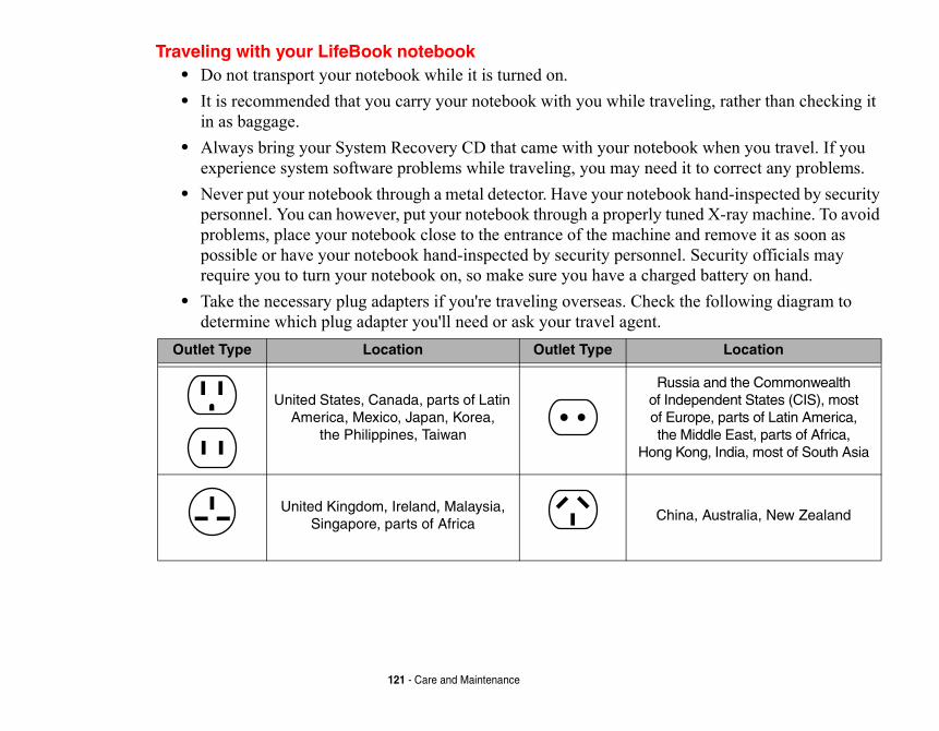
ling, rather than checking it
ok when you travel. If you it to correct any problems. k hand-inspected by security ned X-ray machine. To avoid nd remove it as soon as . Security officials may ed battery on hand. the following diagram to
Location
sia and the Commonwealth ependent States (CIS), most rope, parts of Latin America, Middle East, parts of Africa, ong, India, most of South Asia
na, Australia, New Zealand
121 - Care and Maintenance
Traveling with your LifeBook notebook• Do not transport your notebook while it is turned on. • It is recommended that you carry your notebook with you while trave
in as baggage.• Always bring your System Recovery CD that came with your notebo
experience system software problems while traveling, you may need • Never put your notebook through a metal detector. Have your noteboo
personnel. You can however, put your notebook through a properly tuproblems, place your notebook close to the entrance of the machine apossible or have your notebook hand-inspected by security personnelrequire you to turn your notebook on, so make sure you have a charg
• Take the necessary plug adapters if you're traveling overseas. Check determine which plug adapter you'll need or ask your travel agent.
Outlet Type Location Outlet Type
United States, Canada, parts of Latin America, Mexico, Japan, Korea,
the Philippines, Taiwan
Rusof Indof Euthe
Hong K
United Kingdom, Ireland, Malaysia, Singapore, parts of Africa
Chi
terminals with a metal object). with coins, keys, or other metal
ry.tilated areas.ntense heat can shorten the life
recharging it.
line adapter whenever possible.he AC adapter overnight to
ot actually using it.
122 - Care and Maintenance
Batteries
Caring for your Batteries
• Always handle batteries carefully.• Do not short-circuit the battery terminals (that is, do not touch both
Do not carry lose batteries in a pocket or purse where they may mix objects. Doing so may cause an explosion or fire.
• Do not drop, puncture, disassemble, mutilate or incinerate the batte• Recharge batteries only as described in this manual and only in ven• Do not leave batteries in hot locations for more than a day or two. I
of your battery.• Do not leave a battery in storage for longer than 6 months without
Increasing Battery Life
• Power your LifeBook notebook through the AC or optional auto/air• If your notebook is running on battery power all day, connect it to t
recharge the battery.• Keep brightness to the lowest level comfortable.• Set the power management for maximum battery life.• Put your notebook in sleep mode when it is turned on and you are n• Limit your media drive access.• Disable the Media Player auto insert notification function.• Always use fully charged batteries.• Eject PC Cards when not in use.
ble care.
s use a felt pen.arm condensation may form and let it dry at room
soft, lint free cloth starting
ntion to the following points:
around or subject it to shock
sed to extreme temperatures. strong magnetic fields.
r vibration.
lar maintenance of the drive.
123 - Care and MaintenanceMedia Care
Caring for your Media (DVD/CD/CD-R)
Media discs are precision devices and will function reliably if given reasona
• Always store your media disc in its case when it is not in use.• Always handle discs by the edges and avoid touching the surface.• Avoid storing any media discs in extreme temperatures.• Do not bend media discs or set heavy objects on them.• Do not spill liquids on media discs.• Do not scratch or get dust on media discs.• Never write on the label surface with a ballpoint pen or pencil. Alway• If a media disc is subjected to a sudden change in temperature, cold to w
on the surface. Wipe the moisture off with a clean, soft, lint free clothtemperature. DO NOT use a hair dryer or heater to dry media discs.
• If a disc is dirty, use only a DVD/CD cleaner or wipe it with a clean, from the inner edge and wiping to the outer edge.
Caring for your Optical Drive
The optional optical drive is durable but you must treat it with care. Pay atte
• The drive rotates the compact disc at a very high speed. Do not carry itor vibration with the power on.
• Avoid using or storing the drive where it is damp, dusty, or will be expo• Avoid using or storing the drive near magnets or devices that generate• Avoid using or storing the drive where it will be subjected to shock o• Do not disassemble or dismantle the optical drive.• Use of a commercially available lens cleaner is recommended for regu
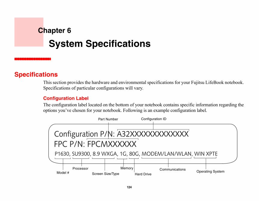
Spe Fujitsu LifeBook notebook.
ic information regarding the on label.
, WIN XPTE
Operating System
124
Chapter 6
System Specifications
cificationsThis section provides the hardware and environmental specifications for yourSpecifications of particular configurations will vary.
Configuration LabelThe configuration label located on the bottom of your notebook contains specifoptions you’ve chosen for your notebook. Following is an example configurati
P1630, SU9300, 8.9 WXGA, 1G, 80G, MODEM/LAN/WLAN
Configuration P/N: A32XXXXXXXXXXXXXFPC P/N: FPCMXXXXXX
Hard Drive
Part Number
ProcessorModel #
Memory
Screen Size/Type
Configuration ID
Communications
multaneous display capability.
84 MB shared video memory
125 - Specifications
MicroprocessorIntel® Core 2™ Duo Processor ULV SU9300
Chipset• Mobile Intel GS45 Express• I/O Controller Hub 9 Mobile (ICH9-MES)
Memory
System Memory
• DDR2-667 MHz SDRAM dual-channel memory module.• One DIMM slot; upgradeable to 2 GB of total memory.
Cache Memory
3 MB L2 cache on-die
VideoBuilt-in color flat-panel TFT active matrix LED backlight display with si
Video Color and Resolution
8.9" Wide XGA display
• Internal: 1280 x 768 pixel resolution, 16M colors• External: 1280 x 1024 pixel resolution, 16M colors• Simultaneous: 1280 x 800, 16M colors
Video RAM
Intel® Graphics Media Accelerator GMA X4500 video graphics. Up to 3using Dynamic Video Memory Technology (DVMT)
um impedance 32 Ohmsimum impedance 10K Ohms
a, 14.4K fax)
r,
communication
126 - Specifications
Audio• Realtek codec ALC269 with High Definition (HD) audio.• Headphones: Stereo headphone jack, 3.5 mm, 1 Vrms or less, minim• Microphone: Stereo microphone jack, 3.5 mm, 100 mVp-p or less, min• One built-in mono speaker, 20 mm diameter• One built-in digital mono microphones
Mass Storage Device Options
Hard Drive
• Serial ATA, 150 Mbps data buffer, 5400 rpm, 1.8”• Shock-mounted• Shock Sensor utility
Features
Integrated Pointing Device
Quick Point cursor control button
Communications
• Modem: Internal V.92 standard 56K fax/modem (ITU V.92, 56K dat• Gigabit LAN: Internal wired 10/100/1000 Gigabit Ethernet LAN• WLAN: Optional Integrated Intel WiFi Link 5300 (533AN_HMW), o
Atheros XSPAN (AR5BHB92)• Bluetooth: Bluetooth V2.1 device for wireless personal area network• Wireless LAN antenna with pre-installed on/off switch
inger over the recognition
ith CardBus support
specifications)ces
127 - Specifications
Trusted Platform Module
Trusted Platform Module (TPM) for added system security.
Theft Prevention Lock
Lock slots for use with security restraint systems.
Fingerprint Recognition Sensor
Allows you to avoid having to enter a username and password by sliding a fsensor.
Device Ports
On the LifeBook notebook:
• PC Card slot for one Type I or Type II card: PCMCIA Standard 2.1 w• Secure Digital (SD) Card slot• One 15-pin D-SUB connector for VGA external monitor (see Display• Two USB 2.0 (Universal Serial Bus) connectors for input/output devi• One DC In connector• One LAN (RJ-45) connector • One modem (RJ-11) connector• Docking port (80-pin, to dock with port replicator)• One stereo headphone jack • One stereo microphone/line-in jack
On the Optional Port Replicator:
• One 15-pin D-SUB connector for VGA external monitor• Four USB 2.0 connectors for input/output devices
r,Ah
des an AC cable
128 - Specifications
• One LAN (RJ-45) connector • One DC-in connector• One Line-Out connector
KeyboardBuilt-in keyboard with all functions of 101 key PS/2 compatible keyboards.
• Total number of keys: 82• Function keys: F1 through F12, plus Fn extension key• Two Windows keys: one Start key, one application key • Key pitch: 16 mm; key stroke: 2.0 mm• Built-in touch screen pointing device• Left and right buttons and scroll button• Quick Point cursor control button• External USB keyboard/mouse support
Power
Batteries
• Standard Lithium ion battery, rechargeable, 3-cell 10.8V, 2600 mAh, o• High capacity 6-cell Lithium ion battery, rechargeable, 10.8V, 5200 m
AC Adapter
Autosensing 100-240V AC, supplying 16V DC, 2.5A, to the LifeBook; inclu
Power Management
Conforms to ACPI (Advanced Configuration and Power Interface).
4.5/37.0 mm)
60° C)
%, relative, non-condensing
r Web site at
129 - Specifications
Dimensions and Weight
Overall Dimensions
Approximately 9.13"(w) x 6.57"(d) x 1.36/1.46”(h) (232 mm x 167 mm x 3
Weight
Approximately 2.2 lb. (1 Kg) with battery
Environmental Requirements
Temperature
Operating: 41° to 95° F (5° to 35° C). Non-operating: 5° to 140° F (–15° to
Humidity
Operating: 20% to 85%, relative, non-condensing. Non-operating: 8% to 85
Altitude
Operating: 10,000 feet (3,048 m) maximum
Popular AccessoriesFor ordering or additional information on Fujitsu accessories please visit ouwww.shopfujitsu.com or call 1-800-FUJITSU.
r playing audio and video ction software and Power th your system.
them upon installation. We cation.
ing system and other pre-ough the help system of the tion on the use of these
130 - Specifications
Included SoftwareDepending on your operating system, your notebook comes with software fofiles of various formats. In addition there is file transfer software, virus proteManagement software. The following list indicates the software included wi
• Adobe Acrobat Reader• Norton Internet Security™ 2008 (90-day free trial)• Google Desktop• Google Tool Bar• Google Picasa• OmniPass Fingerprint application• Fujitsu Driver Update utility• Microsoft Office OneNote 2007 (on select models)• Evernote • PortShutter
Learning About Your Software
Tutorials
All operating systems and most application software have tutorials built intohighly recommend that you step through the tutorial before you use an appli
Manuals
Included with your notebook you will find manuals for your installed operatinstalled software. Any manuals that are not included, are available online thrsoftware. We recommend that you review these manuals for general informaapplications.
from across all of the major
orton Internet Security™ feBook notebook from data currently on your hard our acceptance of software rom Symantec to download
agement capabilities to sword" for all Windows,
e through which you can
web history, and files. It also
on your computer.
rform a variety of other tasks
131 - Specifications
Adobe Acrobat Reader
The Adobe Acrobat Reader allows you to view, navigate, and print PDF filescomputing platforms.
Norton Internet Security 2008
Your system is preinstalled with a free 90-day trial version of Symantec’s N2008. Norton Internet Security is a suite of tools designed to protect your Licomputer viruses, hackers, spyware, and spam. It assists in the protection ofdisk from destruction or contamination. The trial version is activated upon ylicense agreement. After 90 days, you will need to purchase a subscription flatest virus, spyware, and spam definitions.
OmniPass Fingerprint application
The fingerprint sensor uses Softex OmniPass which provides password manMicrosoft Windows operating systems. OmniPass lets you use a "master pasapplications, and on-line passwords, and presents a convenient user interfacsecurely manage passwords, users, and multiple identities for each user.
Google Desktop
Google Desktop lets you to search the contents of your computer for emails, allows you to view news and photos from anywhere on your desktop.
Google Picasa
Google Picasa lets you to search for, locate, move and label all of the photos
Google Toolbar
Google Toolbar lets you to search the Internet quickly, block pop-ups, and peto make your Internet experience easier and more pleasant.
th FDU, you can choose to r your system. See
notebook” so that you can ble place.
ch as typed and handwritten ketches, and documents.
ou to set policies for your hutter, you can:
rmful programs might be
ded.
urations will be installed:
132 - Specifications
Fujitsu Driver Update Utility
The Fujitsu Driver Update (FDU) utility is pre-installed on your system. Wiautomatically or manually go to the Fujitsu site to check for new updates fo“Automatically Downloading Driver Updates” on page 116.
Microsoft OneNote
OneNote lets you collect all of your notes and information in an electronic “organize your pictures, text, notes, and audio/video files in a single, searcha
EverNote
EverNote allows you to capture, store and access a variety of documents, sumemos, webpage excerpts, emails, phone messages, addresses, passwords, s
Portshutter
Portshutter helps to prevent unintended dissemination of data by allowing ysystem that will restrict which ports are available to the end user. With Ports
• Allow no USB devices or only specified USB devices to be used • Prevent confidential from being copied to removable devices• Prevent the connection of external devices, through which illicit or ha
installed or confidential or personal information might be accessed • Temporarily restrict the use of ports when the computer is left unatten
Operating System Options
Depending upon your system, one of the following operating system config
• Microsoft Windows XP Tablet PC Edition• Microsoft Windows XP Professional Edition • Microsoft Windows Vista Business Edition
ltage needed to power your
ic.
r or similar device for every
ork connectivity between , typically known as Access eer fashion.
133
Glossary
AC Adapter
A device which converts the AC voltage from a wall outlet to the DC voLifeBook notebook.
Access point
Wireless network device used to bridge wireless and wired network traff
ACPI
Advanced Configuration and Power Interface
Active-Matrix Display
A type of technology for making flat-panel displays which has a transistopixel on the screen.
Ad Hoc Mode
Ad Hoc Mode refers to a wireless network architecture where wireless netwmultiple computers is established without a central wireless network devicePoints. Connectivity is accomplished using only client devices in a peer-to-p
it-rate services over ordinary
ics-intensive devices, such as
ghter or aircraft DC power
red in ROM which tests and installed operating system ting system to provide it with
either a one (1) or a zero (0).
.
r other storage media into
134 - Glossary
ADSL
Asymmetric Digital Subscriber Line. Technology for transporting high bphone lines.
AGP
Accelerated Graphics Port. Graphics port specifically designed for graphvideo cards and 3D accelerators.
Auto/Airline Adapter
A device which converts the DC voltage from an automobile cigarette lioutlet to the DC voltage needed to power your LifeBook notebook.
BIOS
Basic Input-Output System. A program and set of default parameters stooperates your LifeBook notebook when you turn it on until it loads yourfrom disk. Information from the BIOS is transferred to the installed operainformation on the configuration and status of the hardware.
Bit
An abbreviation for binary digit. A single piece of information which is
bps
An abbreviation for bits per second. Used to describe data transfer rates
Boot
To start-up a computer and load its operating system from disk, ROM oRAM.
semblies inside your LifeBook
er to access than your system handling time faster.
ance similar to the 32-bit PCI
which is read optically with a ut 600MB of data and is not
n there is a failure nor to wear
mit data. IEEE802.11b/g - 11
his is a technology for of power to operate.
135 - Glossary
Bus
An electrical circuit which passes data between the CPU and the sub-asnotebook.
Byte
8 bits of parallel binary information.
Cache Memory
A block of memory built into the micro-processor which is much fastRAM and used in specially structured ways to make your overall data
CardBus
A faster, 32-bit version of the PC Card interface which offers performarchitecture.
CD-ROM
Compact disk read only memory. This is a form of digital data storagelaser rather than a magnetic head. A typical CD-ROM can contain abosubject to heads crashing into the surface and destroying the data whefrom reading.
Channel
Range of narrow-band frequencies used by the WLAN device to transchannels, 22 MHz wide channels.
CMOS RAM
Complementary metal oxide semiconductor random access memory. Tmanufacturing random access memory which requires very low levels
nection.
articular application or format
and how it is allocated for use.
articles striking a luminescent y of the beam.
y with time.
ly acquire parameters required called a DHCP server, and the
136 - Glossary
COM Port
Abbreviation for communication port. This is your serial interface con
Command
An instruction which you give your operating system. Example: run a pa floppy disk.
Configuration
The combination of hardware and software that makes up your system
CRT
Cathode Ray Tube. A display device which uses a beam of electronic pscreen. It produces a visual image by varying the position and intensit
Data
The information a system stores and processes.
DC
Direct current. A voltage or current that does not fluctuate periodicall
Default Value
A pre-programmed value to be used if you fail to set your own.
DHCP
Dynamic Host Configuration Protocol. A protocol used to automaticalfor the communication, such as IP address. The sender of IP address isreceiver is called a DHCP client.
y stiff it is a hard drive, if it is g with a shutter it is commonly
itry for reading and writing the
ers of data which do not require
ment applications with a mputer systems, hardware and
the IP address and the name know the computer name, you
137 - Glossary
DIMM
Dual-in-line memory module.
Disk
A spinning platter of magnetic data storage media. If the platter is verhighly flexible it is a floppy disk, if it is a floppy disk in a hard housincalled a diskette.
Disk Drive
The hardware which spins the disk and has the heads and control circudata on the disk.
Diskette
A floppy disk in a hard housing with a shutter.
DMA
Direct Memory Access. Special circuitry for memory to memory transfCPU action.
DMI
Desktop Management Interface. A standard that provides PC managecommon method of locally or remotely querying and configuring PC cosoftware components, and peripherals.
DNS
Domain Name System. A function to control the association between assigned to the computer. If you do not know the IP address but if youcan still communicate to that computer.
em).
commands to external devices n order to produce the desired
t increases the efficiency of the
unication and interconnection
essage integrity checks. Data
ta, and the identical encryption
tatic charge which has built-up e sparks you get from brushing
138 - Glossary
DOS
Disk Operating System (MS-DOS is a Microsoft Disk Operating Syst
Driver
A computer program which converts application and operating systeminto the exact form required by a specific brand and model of device iresults from that particular equipment.
DVMT
Dynamic Video Memory Technology. A video memory architecture thamotherboard by using innovative memory utilization and direct AGP.
ECP
Extended Capability Port. A set of standards for high speed data commbetween electronic devices.
Encryption Key (Network Key)
Data encryption key used to encrypt message text and for computing mencryption protects data from unauthorized viewing.
This device uses the same encryption key to encode and decode the dakey is required between the sender and receiver.
ESD
Electro-Static Discharge. The sudden discharge of electricity from a sslowly. Example: the shock you get from a doorknob on a dry day or thhair on a dry day.
FCC
Federal Communication Commission.
ible.
very stiff.
orm.
ing your notebook in electronic
e which is inside the hard drive
. 802.11a devices operate in the
802.11b devices operate in the
139 - Glossary
Floppy Disk
A spinning platter of magnetic data storage media which is highly flex
GB
Gigabyte. One billion bytes.
Hard drive
A spinning platter of magnetic data storage media where the platter is
I/O
Input/Output. Data entering and leaving your notebook in electronic f
I/O Port
The connector and associated control circuits for data entering and leavform.
IDE
Intelligent Drive Electronics. A type of control interface for a hard drivunit.
IEEE802.11a
Wireless LAN standard that supports a maximum data rate of 54 Mbps5 GHz lower and middle UNII bands.
IEEE802.11b
Wireless LAN standard that supports a maximum data rate of 11 Mbps.2.4 GHz ISM band.
02.11g devices operate in the
nvisible to humans.
ses an access point. Another
sing the TCP/IP protocol an IP address is a 32-bit ber can be zero to 255. For
ng as each one is unique. istered IP addresses (called
a particular network and a CC and APNIC -- assign
assless scheme called CIDR d to adoption of IPv6.
140 - Glossary
IEEE802.11g
Wireless LAN standard that supports a maximum data rate of 54 Mbps. 82.4 GHz ISM band.
Infrared
Light just beyond the red portion of the visible light spectrum which is i
Infrastructure
A name of a wireless LAN configuration. This type of communication utype of communication is called Ad Hoc.
IP Address
An identifier for a computer or device on a TCP/IP network. Networks uroute messages based on the IP address of the destination. The format ofnumeric address written as four numbers separated by periods. Each numexample, 1.160.10.240 could be an IP address.
Within an isolated network, you can assign IP addresses at random as loHowever, connecting a private network to the Internet requires using regInternet addresses) to avoid duplicates.
The four numbers in an IP address are used in different ways to identifyhost on that network. Three regional Internet registries -- ARIN, RIPE NInternet addresses from the following three classes.
Class A - supports 16 million hosts on each of 126 networks
Class B - supports 65,000 hosts on each of 16,000 networks
Class C - supports 254 hosts on each of 2 million networks
The number of unassigned Internet addresses is running out, so a new clis gradually replacing the system based on classes A, B, and C and is tie

for communication using
an external event has occurred
s within a single limited selves.
trolling the orientation of
s size and is not subject to the
historically line printers were s.
141 - Glossary
IR
An abbreviation for infrared.
IrDA
Infrared Data Association. An organization which produces standardsinfrared as the carrier.
IRQ
Interrupt Request. An acronym for the hardware signal to the CPU thatwhich needs to be processed.
KB
Kilobyte. One thousand bytes.
LAN
Local Area Network. An interconnection of computers and peripheralgeographic location which can pass programs and data amongst them
LCD
Liquid Crystal Display. A type of display which makes images by concrystals in a crystalline liquid.
Lithium ion Battery
A type of rechargeable battery which has a high power-time life for itmemory effect as Nickel Cadmium batteries.
LPT Port
Line Printer Port. A way of referring to parallel interface ports becausethe first and latter the most common device connected to parallel port
rk card. For Ethernet, the first EE. The remaining three bytes thernet card is given a unique from other cards. For Ethernet,
our LifeBook notebook’s CPU.
ocol for exchange of zers.
nects a computer or other data
142 - Glossary
MAC Address
Media Access Control Address. A unique physical address of a netwothree bytes are used as the vendor code, controlled and assigned by IEare controlled by each vendor (preventing overlap), therefore, every Ephysical address in the world, being assigned with a different address frames are sent and received based on this address.
MB
Megabyte. One million bytes.Megahertz
1,000,000 cycles per second.
Memory
A repository for data and applications which is readily accessible to y
MHz
Megahertz.
MIDI
Musical Instrument Digital Interface. A standard communication protinformation between computers and sound producers such as synthesi
Modem
A contraction for MOdulator-DEModulator. The equipment which conterminal to a communication line.
Monaural
A system using one channel to process sound from all sources.
nternet or other networks. You u have difficulty transferring
onal computer uses the same cessary to set the same network
avoid interference or data theft. improve security, the network coincides with the network key.
nd reception for the USA.
ms no authentication checks on
ding driver programs, into the in order to produce the desired
143 - Glossary
MTU
Maximum Transmission Unit
The maximum data size that can be transferred at a time through the Ican set a smaller MTU size to obtain successful communication, if yodata due to the fact that the maximum size is too large.
Network key
Data that is used for encrypting data in data communication. The persnetwork key both for data encryption and decryption, therefore, it is nekey as the other side of communication.
Network name (SSID: Service Set Identifier )
When a wireless LAN network is configured, grouping is performed to This grouping is performed with “Network name (SSID)”. In order tokey is set allowing no communication unless “Network name (SSID)”
NTSC
National TV Standards Commission. The standard for TV broadcast a
Open system authentication
Null authentication method specified in the 802.11 standard that perfora wireless client before allowing it to associate.
Operating System
A group of control programs that convert application commands, incluexact form required by a specific brand and model of microprocessor results from that particular equipment.
o the operating system as if it y.
national Association. The ization that sets standards for
th but not integral to a
. The more pixels per area the
s the configuration and r notebook. Status and error
e self test detects failures that l not be loaded.
oint-to-Point Protocol (PPP),
144 - Glossary
Partition
A block of space on a hard drive which is set aside and made to appear twere a separate disk, and addressed by the operating system accordingl
PCMCIA
PCMCIA is a trademark of the Personal Computer Memory Card InterPersonal Computer Memory Card International Association is an organadd-in cards for personal computers.
Peripheral Device
A piece of equipment which performs a specific function associated wicomputer. Examples: a printer, a modem, a CD-ROM.
Pitch (keyboard)
The distance between the centers of the letter keys of a keyboard.
Pixel
The smallest element of a display, a dot of color on your display screenclearer your image will appear.
POST
Power On Self Test. A program which is part of the BIOS which checkoperating condition of your hardware whenever power is applied to youmessages may be displayed before the operating system is loaded. If thare so serious that operation can not continue, the operating system wil
PPPoE
Point to Point Protocol over Ethernet. A protocol for Ethernet, using a Pwhich is used for connection on the phone line.
hardware what to do and how
.
or correct transfer of
otebook that holds binary r applied to it.
ows the user to add additional
on stored in RAM.
to active operation after having
145 - Glossary
Program
An integrated set of coded commands to your computers telling your and when to do it.
Protocol
Procedures and rules use to send and receive data between computers
- Method of sending and receiving data
- Process used to handle communication errors
Conditions required for communication are organized in procedures finformation.
RAM
Random Access Memory. A hardware component of your LifeBook ninformation (both program and data) as long as it has the proper powe
RAM Module
A printed circuit card with memory and associated circuitry which allmemory to the computer without special tools.
Reset
The act of reloading the operating system. A reset erases all informati
Restart
See Reset.
Resume
To proceed after interruption. In your notebook this refers to returning been in one of the suspension states.
by physically altering the nd does not require power to
at a time on a single wire with
evice a challenge text packet the AP. If the client has the llowed to associate with the r who detects both the clear-
ecipher the key.
various suspension states to
ader of packets sent over a the BSS. The SSID es attempting to connect to a to join the BSS unless it can does not supply any security
146 - Glossary
ROM
Read Only Memory. A form of memory in which information is stored material. Data stored in this way can not be changed by your notebook amaintain it.
SDRAM
Synchronous Dynamic Random Access Memory.
Serial Port
A connection to another device through which data is transferred one bit any other wires only for control of the device not for transfer of data.
Shared key authentication
802.11 network authentication method in which the AP sends the client dthat the client must then encrypt with the correct WEP key and return towrong key or no key, authentication will fail and the client will not be aAP. Shared key authentication is not considered secure, because a hacketext challenge and the same challenge encrypted with a WEP key can d
Sleep
To make inoperative for a period of time. Your LifeBook notebook usesreduce power consumption and prolong the charge of your battery.
SSID
Service Set Identifier, a 32-character unique identifier attached to the heWLAN that acts as a password when a mobile device tries to connect todifferentiates one WLAN from another, so all access points and all devicspecific WLAN must use the same SSID. A device will not be permittedprovide the unique SSID. Because the SSID is broadcast in plain text, itto the network.
e. On your LifeBook notebook
rces.
etworks (subnets). IP address et mask defines how many bits t among computers
r monitor.
on of the system and is counted
protocol that is most widely
147 - Glossary
Status Indicator
A display which reports the condition of some portion of your hardwarthis is an LCD screen just above the keyboard.
Stereo (audio)
A system using two channels to process sound from two different sou
Subnet mask
TCP-IP network is controlled by being divided into multiple smaller nconsists of the subnet address and the address of each computer. Subnof IP address comprise the subnet address. The same value shall be secommunicating with each other.
SVGA
Super VGA.
S-Video
Super Video. A component video system for driving a TV or compute
System Clock
An oscillator of fixed precise frequency which synchronizes the operatito provide time of day and date.
TCP/IP
Transmission Control Protocol/Internet Protocol. A standard Internet used.
a thin film matrix of transistors
d certifies the electrical safety
ct up to 127 USB devices such uter.
y data and control.
tal cost of ownership (TCO) of
eroperability test, supplied by tees the interoperability of -Fi standard, go to the WECA
rs and peripherals within a amongst themselves.
148 - Glossary
TFT
Thin Film Transistor – A technology for flat display panels which uses to control each pixel of the display screen individually.
UL
Underwriters Laboratories – An independent organization that tests anof devices.
USB
Universal Serial Bus. Standard that allows you to simultaneously conneas game pads, pointing devices, printers, and keyboards to your comp
VRAM
Video Random Access Memory. A memory dedicated to video displa
WFM
Wired for Management is Intel’s broad-based initiative to reduce the tobusiness computing without sacrificing power and flexibility.
Wi-Fi Compatible
Wi-Fi (Wireless Fidelity) Identifies that the product has passed the intthe WECA (Wireless Ethernet Compatibility Alliance), which guaranwireless IEEE 802.11 LAN products. For more information on the WiWeb site at: www.wirelessethernet.com.
WLAN
Wireless Local Area Network. A wireless interconnection of computesingle limited geographic location which can pass programs and data
this user’s authority to operate
lass B digital devices, pursuant
ful interference in a residential uency energy and, if not ful interference to radio
l not occur in a particular or television reception, which
couraged to try to correct the
an the receiver.
ensure compliance with the
149 - Regulatory Information
Regulatory Information
NoticeChanges or modifications not expressly approved by Fujitsu could voidthe equipment.
FCC NOTICES
Notice to Users of Radios and Television
This equipment has been tested and found to comply with the limit for cto parts 15 of the FCC Rules.
These limits are designed to provide reasonable protection against harminstallation. This equipment generates, uses, and can radiate radio freqinstalled and used in accordance with the instructions, may cause harmcommunications. However, there is no guarantee that interference wilinstallation. If this equipment does cause harmful interference to radiocan be determined by turning the equipment off and on, the user is eninterference by one or more of the following measures:
• Reorient or relocate the receiving antenna.• Increase the separation between the equipment and receiver.• Connect the equipment into an outlet that is on a different circuit th• Consult the dealer or an experienced radio/TV technician for help.Shielded interconnect cables must be employed with this equipment topertinent RF emission limits governing this device.
ents adopted by ACTA. On ation, the FCC registration
oduct identifier in the format e provided to the telephone
premises wiring using a quipment to the premises rt 68 rules and requirements rovided with this product. It pliant.
n the label. The REN is used e line. Excessive RENs on a ng call. In most but not all number of devices that may l telephone company.
ompany will notify you in if advance notice isn’t sible. Also, you will be necessary.
perations or procedures that e company will provide tain uninterrupted service.
rmation, please refer to the rvice. If the equipment is uest that you disconnect the
150 - Regulatory Information
Notice to Users of the US Telephone Network
This equipment complies with Part 68 of the FCC rules, and the requiremthe bottom of this equipment is a label that contains, among other informnumber and ringer equivalence number (REN) for this equipment; or a prUS:AAAEQ##TXXXX. If requested, this information or number must bcompany.
This equipment is designed to be connected to the telephone network orstandard jack type USOC RJ11C. A plug and jack used to connect this ewiring and telephone network must comply with the applicable FCC Paadopted by the ACTA. A compliant telephone cord and modular plug is pis designed to be connected to a compatible modular jack that is also com
The ringer equivalent number (REN) of this equipment is 0.1B as shown oto determine the number of devices that may be connected to a telephontelephone may result in the devices not ringing in response to an incomiareas, the sum of RENs should not exceed five (5.0). To be certain of thebe connected to a line, as determined by the total RENs, contact the loca
If this equipment causes harm to the telephone network, the telephone cadvance that temporary discontinuance of service may be required. But practical, the telephone company will notify the customer as soon as posadvised of your right to file a complaint with the FCC if you believe it is
The telephone company may make changes in its facilities, equipment, ocould effect the operation of the equipment. If this happens the telephonadvance notice in order for you to make necessary modifications to main
If trouble is experienced with this equipment, for repair or warranty infomanual or contact Fujitsu Computer Systems Corporation, Customer Secausing harm to the telephone network, the telephone company may reqequipment until the problem is resolved.

lephone company. Connection utility commission, public
lephone line, ensure the you have any questions about r a qualified installer.
r any person to use a computer chine unless such message age or on the first page of the siness or other entity, or other ing machine or such business,
erference-Causing Equipment
Réglement sur le matérial
inal Equipment Technical reviation, IC, before the a Declaration of Conformity oes not imply that Industry
151 - Regulatory Information
The equipment cannot be used on public coin service provided by the teto party line service is subject to state tariffs. (Contact the state publicservice commission or corporation commission for information).
If your home has specially wired alarm equipment connected to the teinstallation of this computer does not disable your alarm equipment. Ifwhat will disable alarm equipment, consult your telephone company o
The Telephone Consumer Protection Act of 1991 makes it unlawful foor other electronic device to send any message via a telephone fax maclearly contains in a margin at the top or bottom of each transmitted ptransmission, the date an time it is sent and an identification of the buindividual sending the message and the telephone number of the sendother entity, or individual.
DOC (INDUSTRY CANADA) NOTICES
Notice to Users of Radios and Television
This Class B digital apparatus meets all requirements of Canadian IntRegulations.
CET appareil numérique de la class B respecte toutes les exigence dubrouilleur du Canada.
Notice to Users of the Canadian Telephone Network
NOTICE: This equipment meets the applicable Industry Canada TermSpecifications. This is confirmed by the registration number. The abbregistration number signifies that registration was performed based onindicating that Industry Canada technical specifications were met. It dCanada approved the equipment.
nsure that it is permissible to user should be aware that egradation in some situations.
ian authorized maintenance r any equipment failures may onnect the equipment from the
quipment is 0.1B. The REN ximum number of terminals n interface may consist of any f the Ringer Equivalence
d’Industrie Canada applicables enregistrement. Le sigle IC, s’est effectué conformément à ues d’Industrie Canada ont été iel.
ND OF THE POWER UTILITY, THE D TOGETHER. USERS SHOULD
OULD CONTACT THE APPROPRIATE RTICULARLY IMPORTANT IN RURAL
152 - Regulatory Information
Before connecting this equipment to a telephone line the user should econnect this equipment to the local telecommunication facilities. The compliance with the certification standards does not prevent service d
Repairs to telecommunication equipment should be made by a Canadfacility. Any repairs or alterations not expressly approved by Fujitsu ogive the telecommunication company cause to request the user to disctelephone line.
NOTICE: The Ringer Equivalence Number (REN) for this terminal eassigned to each terminal equipment provides an indication of the maallowed to be connected to a telephone interface. The termination on acombination of devices subject only to the requirement that the sum oNumbers of all the devices does not exceed five.
Avis Aux Utilisateurs Du Réseau Téléphonique Canadien
AVIS: Le présent matériel est conforme aux spécifications techniques au matériel terminal. Cette conformité est confirmée par le numéro d’placé devant le numéro d’enregistrement, signifie que l’enregistrementune déclaration de conformité et indique que les spécifications techniqrespectées. Il n’implique pas qu’Industrie Canada a approuvé le matér
FOR SAFETY, USERS SHOULD ENSURE THAT THE ELECTRICAL GROU
TELEPHONE LINES AND THE METALLIC WATER PIPES ARE CONNECTE
NOT ATTEMPT TO MAKE SUCH CONNECTIONS THEMSELVES BUT SH
ELECTRIC INSPECTION AUTHORITY OR ELECTRICIAN. THIS MAY BE PA
AREAS.
teur doit vérifier s’il est permis locales. L’utilisateur est averti ns cas empêcher la dégradation
ffectuées par un service de ’est pas expressément îner la compagnie de t de la ligne téléphonique.
l est de 0.1B. L’IES assigné à ui peuvent être raccordés à une n une combinaison quelconque ce de la sonnerie de tous les
QUE LA PRISE DE TERRE DU ITES D’EAU MÉTALLIQUES SONT TER D’ÉTABLIR CES CONNEXIONS N D’INSTALLATIONS ÉLECTRIQUES ENT IMPORTANT EN RÉGIONS
153 - Regulatory Information
Avant de connecter cet équipement à une ligne téléphonique, l’utilisade connecter cet équipement aux installations de télécommunications que même la conformité aux normes de certification ne peut dans certaidu service.
Les réparations de l’équipement de télécommunications doivent être emaintenance agréé au Canada. Toute réparation ou modification, qui napprouvée par Fujitsu, ou toute défaillance de l’équipement peut entratélécommunications à exiger que l’utilisateur déconnecte l’équipemen
AVIS: L’indice d’équivalence de la sonnerie (IES) du présent matériechaque dispositif terminal indique le nombre maximal de terminaux qinterface téléphonique. La terminaison d’une interface peut consister ede dispositifs, à la seule condition que la somme d’indices d’équivalendispositifs n’excède pas 5.
POUR ASSURER LA SÉCURITÉ, LES UTILISATEURS DOIVENT VÉRIFIER
SERVICE D’ÉLECTRICITÉ, LES LIGNES TÉLPHONIQUES ET LES CONDU
CONNECTÉES ENSEMBLE. LES UTILISATEURS NE DOIVENT PAS TEN
EUX-MÊMES, MAIS DOIVENT CONTACTER LES SERVICES D’INSPECTIO
APPROPRIÉS OU UN ÉLECTRICIEN. CECI PEUT ÊTRE PARTICULIÈREM
RURALES.
ide
ireless LAN device.
gy levels of these emissions, however, obile phones. Wireless LAN devices
frequency safety standards and s or environments, such as:
rceived or identified as harmful.
ents is not clear (e.g., airports, se these devices prior to operating the
154
Appendix A: WLAN User’s Gu
FCC Regulatory InformationPlease note the following regulatory information related to the optional w
Regulatory Notes and Statements
Wireless LAN, Health and Authorization for use Radio frequency electromagnetic energy is emitted from Wireless LAN devices. The enerare much less than the electromagnetic energy emissions from wireless devices such as mare safe for use by consumers because they operate within the guidelines found in radio recommendations. The use of Wireless LAN devices may be restricted in some situation
• On board an airplane, or
• In an explosive environment, or
• In situations where the interference risk to other devices or services is pe
In cases in which the policy regarding use of Wireless LAN devices in specific environmhospitals, chemical/oil/gas industrial plants, private buildings), obtain authorization to uequipment.
structions included in the user vice that are not expressly approved
cturer is not responsible for any radio stitution or attachment of connecting lity of the user to correct any manufacturer and its authorized nt regulations arising from failure to
transmitter.
e, it is restricted to indoor
rference, and, (2) This device must s device.
evice, pursuant to Part 15 of the FCC ence in a residential installation. This d in accordance with the instructions, tee that interference will not occur in
can be determined by turning the r more of the following measures:
eiver is connected to.
155
Regulatory Information/Disclaimers
Installation and use of this Wireless LAN device must be in strict accordance with the indocumentation provided with the product. Any changes or modifications made to this deby the manufacturer may void the user’s authority to operate the equipment. The manufaor television interference caused by unauthorized modification of this device, or the subcables and equipment other than those specified by the manufacturer. It is the responsibiinterference caused by such unauthorized modification, substitution or attachment. The resellers or distributors will assume no liability for any damage or violation of governmecomply with these guidelines.
This device must not be co-located or operated in conjunction with any other antenna or
For IEEE 802.11a Wireless LAN: For operation within 5.15~5.25 GHz frequency rangenvironments, and the antenna of this device must be integral.
Federal Communications Commission statement
This device complies with Part 15 of FCC Rules.
Operation is subject to the following two conditions: (1) This device may not cause inteaccept any interference, including interference that may cause undesired operation of thi
FCC Interference Statement This equipment has been tested and found to comply with the limits for a Class B digital dRules. These limits are designed to provide reasonable protection against harmful interferequipment generates, uses, and can radiate radio frequency energy. If not installed and useit may cause harmful interference to radio communications. However, there is no guarana particular installation.
If this equipment does cause harmful interference to radio or television reception, whichequipment off and on, the user is encouraged to try and correct the interference by one o
1 Reorient or relocate the receiving antenna.
2 Increase the distance between the equipment and the receiver.
3 Connect the equipment to an outlet on a circuit different from the one the rec
4 Consult the dealer or an experienced radio/TV technician for help.
Figure A-1. Ad Hoc Mode Network

w power wireless devices. There is no es emit low levels of radio frequency
effects (by heating tissue), exposure to ies of low-level RF exposure have not
but such findings have not been ly with FCC radiation exposure limits
es in Supplement C to OET65.
d from the US or Canada without 15 of FCC Rules., as well as ICES ay not cause harmful interference,
cause undesirable operation. the user's right to operate this
harmful interference to co-channel
- 5725 MHz and 5725 - 5825 MHz
users (meaning they have priority) r damage to LE-LAN devices.
156
FCC Radio Frequency Exposure statement The available scientific evidence does not show that any health problems are associated with using loproof, however, that these low power wireless devices are absolutely safe. Low power wireless devicenergy (RF) in the microwave range while being used. Whereas high levels of RF can produce healthlow-level RF that does not produce heating effects causes no known adverse health effects. Many studfound any biological effects. Some studies have suggested that some biological effects might occur, confirmed by additional research. The wireless LAN radio device has been tested and found to compset forth for an uncontrolled equipment and meets the FCC radio frequency (RF) Exposure Guidelin
Export restrictions
This product or software contains encryption code which may not be exported or transferrean approved US Department of Commerce export license. This device complies with Part 003 B / NMB 003 B. Operation is subject to the following two conditions: (1) this device mand (2) this device must accept any interference received, including interference that may Modifications not expressly authorized by Fujitsu Computer Systems Corp. may invalidateequipment.
Canadian Notice The device for the 5150 - 5250 MHz band is only for indoor usage to reduce the potential formobile satellite systems.
The maximum antenna gain of 6 dBi permitted (for devices in the 5250 - 5350 MHz, 5470 bands) to comply with the e.i.r.p. limit as stated in A9.2 of RSS210.
In addition, users are cautioned to take note that high power radars are allocated as primaryof 5250 - 5350 MHz and 5650 - 5850 MHz and these radars could cause interference and/o
figure the optional integrated t of the manual). Before using on. Keep this manual in a safe
ptional devices:
obile computer.
d to procure an FCC operating ical (ISM) RF band and the lower, frastructure (UNII) bands.
EEE802.11b, IEEE802.11g, and
maximum data rate of 540 Mbps E802.11g mode; and 11 Mbps in
P, CKIP, and AES encryption.
A, WPA2, CCX1.0, CCX2.0,
157 Before Using the Optional Wireless LAN
Before Using the Optional Wireless LANThis manual describes the procedures required to properly set up and conWireless LAN Mini-PCI device (referred to as "WLAN device" in the resthe WLAN device, read this manual carefully to ensure its correct operatiplace for future reference.
Wireless LAN Device Covered by this DocumentThis document is applicable to systems containing one of the following o
• Integrated Intel WiFi Link 5300 (533AN_HMW)• Atheros XSPAN (AR5BHB92)
Characteristics of the WLAN Device• The WLAN device is a Mini-PCI card attached to the main board of the m
• The WLAN device operates in license-free RF bands, eliminating the neelicense. The WLAN operates in the 2.4GHz Industrial, Scientific, and Medmiddle, and upper bands of the 5GHz Unlicensed National Information In
• The WLAN devices are capable of four operating modes, IEEE802.11a, IIEEE802.11n (draft)
• The WLAN devices are Wi-Fi certified and operate (as applicable) at a the(theoretical) in IEEE802.11n (draft) mode; 54 Mbps in IEEE802.11a or IEEIEEE802.11b mode.
• The WLAN devices support the following encryption methods - WEP, TKI
• The Wireless LAN devices are compliant with the following standards: WPCCX3.0, and CCX4.0.
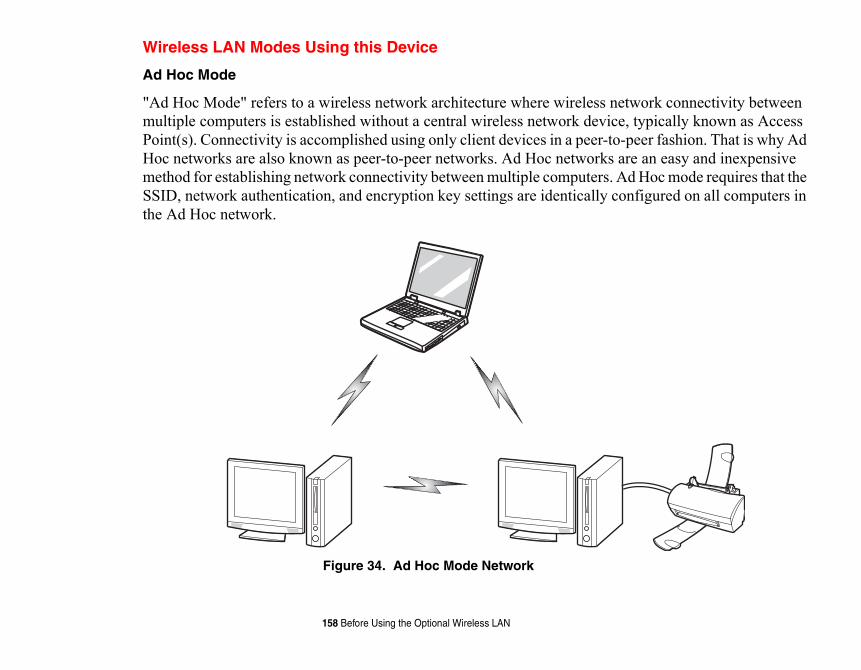
twork connectivity between , typically known as Access peer fashion. That is why Ad re an easy and inexpensive d Hoc mode requires that the nfigured on all computers in
158 Before Using the Optional Wireless LAN
Wireless LAN Modes Using this Device
Ad Hoc Mode
"Ad Hoc Mode" refers to a wireless network architecture where wireless nemultiple computers is established without a central wireless network devicePoint(s). Connectivity is accomplished using only client devices in a peer-to-Hoc networks are also known as peer-to-peer networks. Ad Hoc networks amethod for establishing network connectivity between multiple computers. ASSID, network authentication, and encryption key settings are identically cothe Ad Hoc network.
Figure 34. Ad Hoc Mode Network
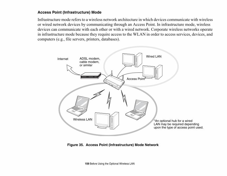
devices communicate with wireless t. In infrastructure mode, wireless orporate wireless networks operate der to access services, devices, and
rk
LAN
*An optional hub for a wiredLAN may be required dependingupon the type of access point used.
159 Before Using the Optional Wireless LAN
Access Point (Infrastructure) Mode
Infrastructure mode refers to a wireless network architecture in which or wired network devices by communicating through an Access Poindevices can communicate with each other or with a wired network. Cin infrastructure mode because they require access to the WLAN in orcomputers (e.g., file servers, printers, databases).
Figure 35. Access Point (Infrastructure) Mode Netwo
ADSL modem,cable modem,or similar
InternetWired
Access Point*
Wireless LAN
our mobile computer. Under install it. The operating system t the WLAN device.
.11g, and IEEE802.11n.
r, middle, and upper UNII bands.
they operate in the same 2.4 GHz does not occur with IEEE802.11a
eration of WLAN devices in ughput, intermittent disconnects, devices be powered off to ensure
to extend battery life) or where WLAN device can be d in Windows using the WLAN tray does not turn off the radio;
LL CLICKME! TO ENSURE THAT THE LING CLICKME!” ON PAGE 73.
160 Before Using the Optional Wireless LAN
How to Handle This Device
The WLAN device is an optional device that may come pre-installed in ynormal circumstances, it should not be necessary for you to remove or re-that your mobile computer comes with has been pre-configured to suppor
• The Wireless LAN devices support IEEE802.11a, IEEE802.11b, IEEE802
• The WLAN devices operate in the 2.4 GHz ISM band and the 5 GHz lowe
• Microwave ovens may interfere with the operation of WLAN devices since frequency range as IEEE802.11b/g/n devices. Interference by microwavesradio which operates in the 5 GHz RF band.
• Wireless devices that transmit in the 2.4 GHz range may interfere with opIEEE802.11b/g/n modes. Symptoms of interference include reduced throand many frame errors. It is HIGHLY recommended that these interfering proper operation of the WLAN device.
Deactivating/Disconnecting the WLAN DeviceDisconnecting the WLAN device may be desired in certain circumstances (certain environments require it (i.e. hospitals, clinics, airplanes, etc.). Thedeactivated by using the Wireless On/Off Switch, and it can be disconnecteicon in the system tray (Note that disconnecting via the icon in the system it continues to transmit and receive even though it’s not connected.).
BEFORE USING THE WIRELESS LAN DEVICE, YOU MUST FIRST INSTA
CORRECT SOFTWARE FOR YOUR DEVICE IS INSTALLED. SEE “INSTAL
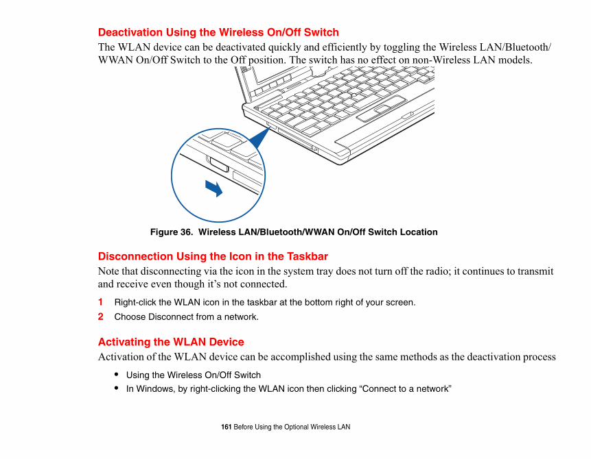
the Wireless LAN/Bluetooth/ n-Wireless LAN models.
tion
e radio; it continues to transmit
ods as the deactivation process
etwork”
161 Before Using the Optional Wireless LAN
Deactivation Using the Wireless On/Off SwitchThe WLAN device can be deactivated quickly and efficiently by togglingWWAN On/Off Switch to the Off position. The switch has no effect on no
Figure 36. Wireless LAN/Bluetooth/WWAN On/Off Switch Loca
Disconnection Using the Icon in the TaskbarNote that disconnecting via the icon in the system tray does not turn off thand receive even though it’s not connected.1 Right-click the WLAN icon in the taskbar at the bottom right of your screen.
2 Choose Disconnect from a network.
Activating the WLAN DeviceActivation of the WLAN device can be accomplished using the same meth
• Using the Wireless On/Off Switch
• In Windows, by right-clicking the WLAN icon then clicking “Connect to a n
connectivity using the d security solutions is
ith your network
l. Double-click the Network and
tion. For an infrastructure Create an ad hoc network”.
ator for some of the information.
dow (Start -> Control Panel -> .
ork by performing the
162 Configuring the Wireless LAN
Configuring the Wireless LANThe optional WLAN device can be configured to establish wireless networksoftware that is built into Windows Vista. Support for most industry standarcontained in this software.
Pre-defined parameters will be required for this procedure. Please consult wadministrator for these parameters:
Configuring the WLAN Using Windows Vista1 Click the Start button, then select Control Panel.
2 If the Control Panel is not in Classic View, select Classic View from the left paneSharing Center icon.
3 Select “Manage wireless networks” from the left panel.
4 Click on the [Add] button.
5 Depending upon what type of connection you would like to make, make a selecnetwork, select “Manually create a network profile. For ad hoc network, select “
6 Enter the required information. If necessary, consult with your network administr
7 In the event you require assistance, go to the Network and Sharing Center winNetwork and Sharing Center), and type in relevant keywords in the Search box
Connecting to a Network
After you have configured your computer, you can connect to an active netwfollowing steps:1 Click on the WLAN icon in the system tray.
2 Select “Connect to a network”.
3 Select a network from the list that appears, and click the [Connect] button.
el. Double-click the Network
k administrator for some of the
rking and the Web. Select the arch box.
ork by clicking on the
163 Configuring the Wireless LAN
Configuring the WLAN Using Windows XP
Procedure
1 Click the Start button, then select Control Panel.
2 If the Control Panel is not in Classic View, select Classic View from the left panConnections icon.
3 Double-click on the Wireless Network Connection icon.
4 Choose a wireless network.
5 Click [Connect].
6 Enter the Network Key, if required.
7 Enter any required information. It may be necessary to consult with your networinformation.
8 In the event you require assistance, go to [Start] -> Help and Support -> Netwomain topic in which you are interested, then type in relevant keywords in the Se
Connection to the networkAfter you have configured your computer, you can connect to an active netwWireless Network icon in the system tray:
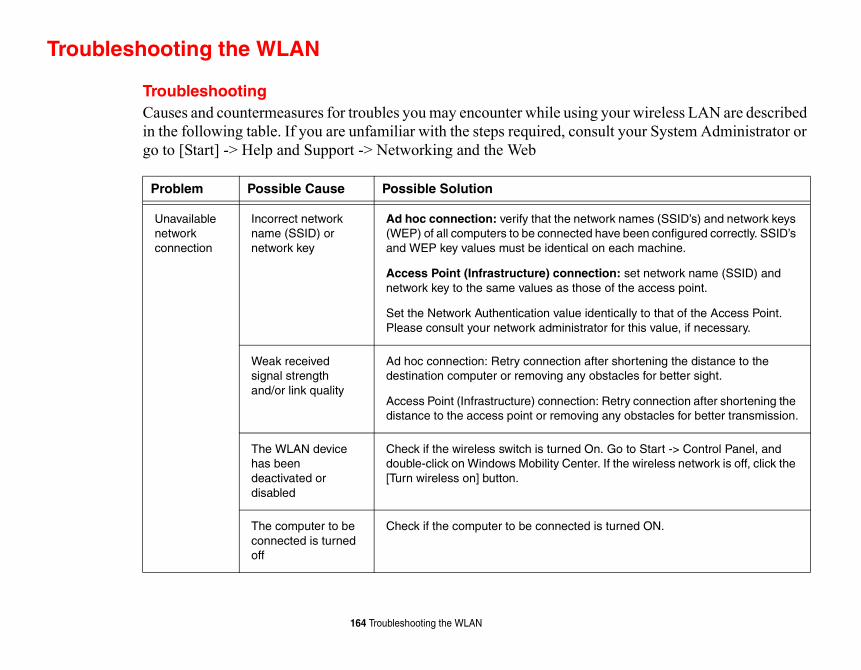
wireless LAN are described ur System Administrator or
mes (SSID’s) and network keys een configured correctly. SSID’s h machine.
et network name (SSID) and e access point.
ly to that of the Access Point. this value, if necessary.
rtening the distance to the es for better sight.
connection after shortening the bstacles for better transmission.
o Start -> Control Panel, and wireless network is off, click the
ed ON.
164 Troubleshooting the WLAN
Troubleshooting the WLAN
TroubleshootingCauses and countermeasures for troubles you may encounter while using yourin the following table. If you are unfamiliar with the steps required, consult yogo to [Start] -> Help and Support -> Networking and the Web
Problem Possible Cause Possible Solution
Unavailable network connection
Incorrect network name (SSID) or network key
Ad hoc connection: verify that the network na(WEP) of all computers to be connected have band WEP key values must be identical on eac
Access Point (Infrastructure) connection: snetwork key to the same values as those of th
Set the Network Authentication value identicalPlease consult your network administrator for
Weak received signal strength and/or link quality
Ad hoc connection: Retry connection after shodestination computer or removing any obstacl
Access Point (Infrastructure) connection: Retrydistance to the access point or removing any o
The WLAN device has been deactivated or disabled
Check if the wireless switch is turned On. Go tdouble-click on Windows Mobility Center. If the[Turn wireless on] button.
The computer to be connected is turned off
Check if the computer to be connected is turn
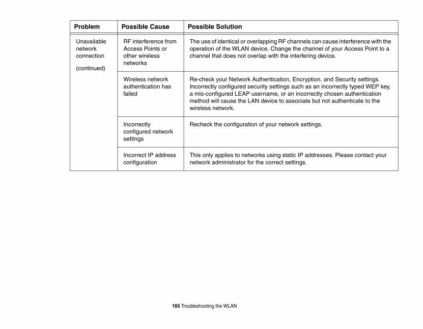
ls can cause interference with the hannel of your Access Point to a ring device.
ption, and Security settings. as an incorrectly typed WEP key, rrectly chosen authentication te but not authenticate to the
ttings.
ddresses. Please contact your .
165 Troubleshooting the WLAN
Unavailable network connection
(continued)
RF interference from Access Points or other wireless networks
The use of identical or overlapping RF channeoperation of the WLAN device. Change the cchannel that does not overlap with the interfe
Wireless network authentication has failed
Re-check your Network Authentication, EncryIncorrectly configured security settings such a mis-configured LEAP username, or an incomethod will cause the LAN device to associawireless network.
Incorrectly configured network settings
Recheck the configuration of your network se
Incorrect IP address configuration
This only applies to networks using static IP anetwork administrator for the correct settings
Problem Possible Cause Possible Solution
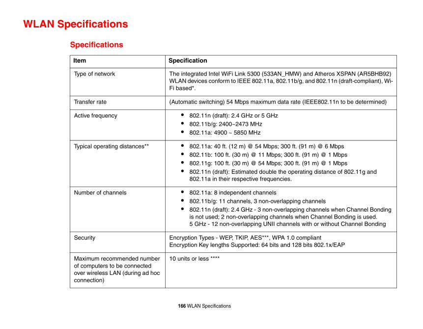
nd Atheros XSPAN (AR5BHB92) nd 802.11n (draft-compliant), Wi-
EEE802.11n to be determined)
m) @ 6 Mbps1 m) @ 1 Mbps1 m) @ 1 Mbps
ng distance of 802.11g and
hannels channels when Channel Bonding n Channel Bonding is used. ith or without Channel Bonding
pliant its 802.1x/EAP
166 WLAN Specifications
WLAN Specifications
Specifications
Item Specification
Type of network The integrated Intel WiFi Link 5300 (533AN_HMW) aWLAN devices conform to IEEE 802.11a, 802.11b/g, aFi based*.
Transfer rate (Automatic switching) 54 Mbps maximum data rate (I
Active frequency • 802.11n (draft): 2.4 GHz or 5 GHz• 802.11b/g: 2400~2473 MHz
• 802.11a: 4900 ~ 5850 MHz
Typical operating distances** • 802.11a: 40 ft. (12 m) @ 54 Mbps; 300 ft. (91• 802.11b: 100 ft. (30 m) @ 11 Mbps; 300 ft. (9• 802.11g: 100 ft. (30 m) @ 54 Mbps; 300 ft. (9
• 802.11n (draft): Estimated double the operati802.11a in their respective frequencies.
Number of channels • 802.11a: 8 independent channels
• 802.11b/g: 11 channels, 3 non-overlapping c• 802.11n (draft): 2.4 GHz - 3 non-overlapping
is not used; 2 non-overlapping channels whe5 GHz - 12 non-overlapping UNII channels w
Security Encryption Types - WEP, TKIP, AES***, WPA 1.0 comEncryption Key lengths Supported: 64 bits and 128 b
Maximum recommended number of computers to be connected over wireless LAN (during ad hoc connection)
10 units or less ****

e interconnectivity of
number of walls, reflective
users can set 40 bits/ 104
may be decreased.
167 WLAN Specifications
* “Wi-Fi based” indicates that the interconnectivity test of the organization which guarantees thwireless LAN (Wi-Fi Alliance) has been passed.
** The communication ranges shown above will increase or decrease depending on factors such asmaterial, or interference from external RF sources.
*** Encryption with network key (WEP) is performed using the above number of bits, however, bits after subtracting the fixed length of 24 bits.
**** Depending on practical environments, the allowable number of computers to be connected
ailable for Fujitsu mobile
obile devices, such as laptop create Personal Area Networks
learning about operation of the
k on Toshiba. Select Bluetooth,
click on Bluetooth, then select
th Web site at:
F BOTH THE OPTIONAL WIRELESS DISABLE EITHER ONE OF THE
on.
th and/or Wireless LAN Status to
168 Using the Bluetooth Device
Using the Bluetooth DeviceThe Integrated Bluetooth module (EYTF3CSFT) is an optional device avcomputers.
What is BluetoothBluetooth technology is designed as a short-range wireless link between mcomputers, phones, printers, and cameras. Bluetooth technology is used to (PANs) between devices in short-range of each other.
Where to Find Information About BluetoothThe Bluetooth module contains a robust Help user’s guide to assist you in Bluetooth device.
Windows XP: To access the Help file, click [Start] > All Programs, and clicthen select User’s Guide.
Windows Vista: To access the Help file, click [Start] > All Programs, and User’s Guide.
For additional information about Bluetooth Technology, visit the Bluetoowww.bluetooth.com.
THE WIRELESS LAN/BLUETOOTH ON/OFF SWITCH WILL POWER OF
LAN AND BLUETOOTH DEVICES AT THE SAME TIME. TO ENABLE OR DEVICES INDIVIDUALLY, PERFORM THE FOLLOWING STEPS:
1 Slide the Wireless LAN/Bluetooth on/off switch to On positi
2 In the Control Panel, click the button associated with Bluetooenable or disable the individual devices.
3 Click [OK].
an uncontrolled environment. nd is exempt from minimum
nction with any other antenna
d to be operated indoors and nsmit antenna) that is installed
date the warranty.
out signed written permission ation from the FCC and
169 Using the Bluetooth Device
FCC Radiation Exposure Statement
This equipment complies with FCC radiation exposure limits set forth forThe Bluetooth antenna is located on the front edge of the right palm rest adistance criteria due to its low power.
The transmitters in this device must not be co-located or operated in conjuor transmitter.
Canadian Notice
To prevent radio interference to the licensed service, this device is intendeaway from windows to provide maximum shielding. Equipment (or its traoutdoors is subject to licensing.
Warranty
Users are not authorized to modify this product. Any modifications invali
This equipment may not be modified, altered, or changed in any way withfrom Fujitsu. Unauthorized modification will void the equipment authorizIndustry Canada and the warranty.
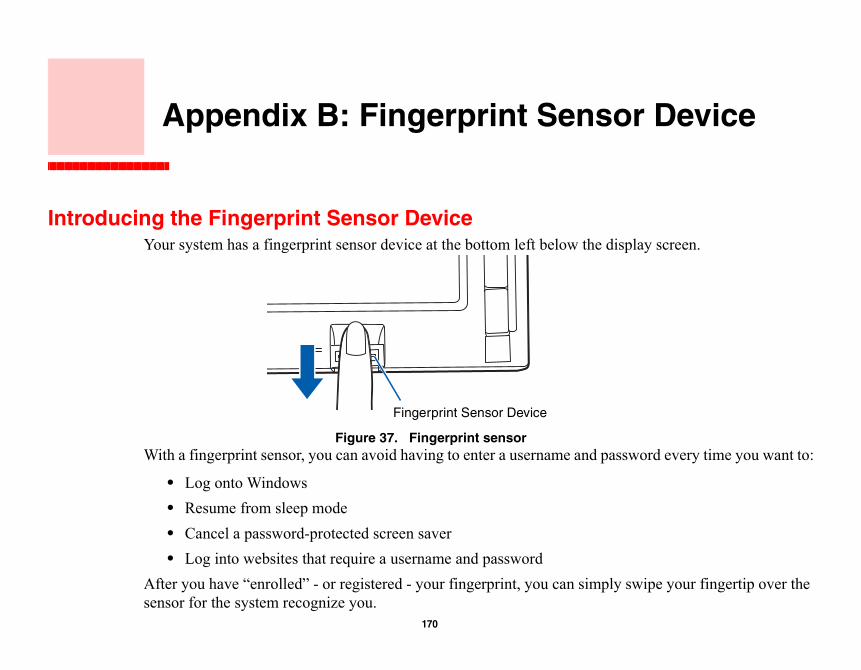
r Device
Introlay screen.
word every time you want to:
wipe your fingertip over the
170
Appendix B: Fingerprint Senso
ducing the Fingerprint Sensor DeviceYour system has a fingerprint sensor device at the bottom left below the disp
Figure 37. Fingerprint sensorWith a fingerprint sensor, you can avoid having to enter a username and pass
• Log onto Windows• Resume from sleep mode• Cancel a password-protected screen saver• Log into websites that require a username and password
After you have “enrolled” - or registered - your fingerprint, you can simply ssensor for the system recognize you.
Fingerprint Sensor Device
agement capabilities to ter password" for all
or before granting access to or restricting access to your
can securely manage
Pass fingerprint recognition will also be led through the
go directly to “User been installed by checking
ight of the screen.
ALLOWS THE USER TO LOG IN NMENT SERVES AS AN
E SECURE ENVIRONMENT
171 - Introducing the Fingerprint Sensor Device
The fingerprint sensor uses Softex OmniPass which provides password manMicrosoft Windows operating systems. OmniPass enables you to use a "masWindows, applications, and on-line passwords.
OmniPass requires users to authenticate themselves using the fingerprint sensthe Windows desktop. This device results in a secure authentication system fcomputer, applications, web sites, and other password-protected resources.
OmniPass presents a convenient graphical user interface, through which youpasswords, users, and multiple identities for each user.
Getting StartedThis section guides you through the preparation of your system for the Omniapplication. You will be led through the OmniPass installation process. You procedure of enrolling your first user into OmniPass.
Installing OmniPassIf OmniPass has already been installed on your system, skip this section andEnrollment” on page 174. You can determine whether OmniPass has alreadyto see if the following are present:
• The gold key-shaped OmniPass icon in the system tray at the bottom r• The Softex program group in the Programs group of the Start menu
CERTAIN MODELS SUPPORT PRE-BOOT AUTHENTICATION OR PBA. PBAPRIOR TO WINDOWS' OWN AUTHENTICATION MECHANISM. A PBA ENVIRO
EXTENSION OF THE BIOS OR BOOT FIRMWARE AND ALLOWS FOR A MOR
EXTERNAL TO THE OPERATING SYSTEM.
specific Operating Systems
page 174. Otherwise
rive. If you are installing from gram (setup.exe) from the
ocation to which you would like ot directory (e.g. C:\).
ystem. Once your system has ely after installation, OmniPass
Windows Control Panel as well
EXTERNAL OPTICAL DRIVE
ING OMNIPASS HAVE SER DOES NOT HAVE ADMINISTRATOR USER BEFORE
172 - Introducing the Fingerprint Sensor Device
System Requirements
The OmniPass application requires space on your hard drive; it also requires(OS’s). The minimum requirements are as follows:
• Windows XP Professional operating system• At least 35 MB available hard disk space
Installing the OmniPass Application
If OmniPass is already installed on your system, go to “User Enrollment” oncontinue with this section on software installation.
To install OmniPass on your system you must:1 Insert the installation media for the OmniPass application into the appropriate d
CD-ROM or DVD-ROM, you must find and launch the OmniPass installation promedia.
2 Follow the directions provided in the OmniPass installation program. Specify a lOmniPass installed. It is recommended that you NOT install OmniPass in the ro
3 Once OmniPass has completed installation you will be prompted to restart you srebooted you will be able to use OmniPass. If you choose not to restart immediatwill not be available for use until the next reboot.
4 The installation program automatically places an icon (Softex OmniPass) in the as a golden key shaped icon in the taskbar.
• INSTALLATION OF THE APPLICATION REQUIRES THAT YOU HAVE AN ATTACHED TO YOUR SYSTEM.
• FOR INSTALLATION, OMNIPASS REQUIRES THAT THE USER INSTALL
ADMINISTRATIVE PRIVILEGES TO THE SYSTEM. IF YOUR CURRENT UADMINISTRATIVE PRIVILEGES, LOG OUT AND THEN LOG IN WITH AN PROCEEDING WITH OMNIPASS INSTALLATION.
u may wish to check the
taskbar (usually located in the
Windows XP you will see the iew). Double-click Softex If it does not appear, then the
ex program group, from that
window appears with version
LING OMNIPASS HAVE DOES NOT HAVE INISTRATOR USER BEFORE
173 - Introducing the Fingerprint Sensor Device
Verifying Information about OmniPass
After you have completed installing OmniPass and restarted your system, yoversion of OmniPass on your system.
To check the version information of OmniPass:
1 From the Windows Desktop, double-click the key-shaped OmniPass icon in the lower right corner of the screen), or, Click the Start button, select Settings, and click Control Panel (if you are usingControl Panel directly in the Start menu; click it, then click Switch to Classic VOmniPass in the Control Panel, and the OmniPass Control Center will appear.program is not properly installed, or, Click the Start button, select Programs, and from the submenu select the Softsubmenu click OmniPass Control Center.
2 Select the About tab at the top of the OmniPass Control Panel. The About tab information about OmniPass.
Uninstalling OmniPass
To remove the OmniPass application from your system:1 Click Start on the Windows taskbar. Select Settings, and then Control Panel.
2 Double-click Add/Remove Programs.
3 Select OmniPass, and then click Change/Remove.
4 Follow the directions to uninstall the OmniPass application.
5 Once OmniPass has finished uninstalling, reboot your system when prompted.
FOR UNINSTALLATION, OMNIPASS REQUIRES THAT THE USER UNINSTAL
ADMINISTRATIVE PRIVILEGES TO THE SYSTEM. IF YOUR CURRENT USER
ADMINISTRATIVE PRIVILEGES, LOG OUT AND THEN LOG IN WITH AN ADM
PROCEEDING WITH OMNIPASS UNINSTALLATION.
mniPass.
gging into your computer, esources, you often have to tials that you have to
This master password
r) and enrolls an OmniPass ebmail site to log onto his
d password “lifebook”), but Now whenever he returns to
mniPass authentication any web sites or password
s OmniPass user credentials the system onto which he ls of the password protected ccess his webmail, he would gain access. If he attempts on, he will not gain access.
THENTICATION DEVICES OR OMNIPASS. IF YOU DESIRE DOCUMENT.
174 - Introducing the Fingerprint Sensor Device
User EnrollmentBefore you can use any OmniPass features you must first enroll a user into OMaster Password Concept
Computer resources are often protected with passwords. Whether you are loaccessing your email, e-banking, paying bills online, or accessing network rsupply credentials to gain access. This can result in dozens of sets of credenremember.
During user enrollment a "master password” is created for the enrolled user.“replaces” all other passwords for sites you register with OmniPass.
Example: A user, John, installs OmniPass on his system (his home computeuser with username “John_01” and password “freq14”. He then goes to his waccount. He inputs his webmail credentials as usual (username “John_02” aninstead of clicking [Submit], he directs OmniPass to Remember Password. that site, OmniPass will prompt him to supply access credentials.
John enters his OmniPass user credentials (“John_01” and “freq14”) in the Oprompt, and he is allowed into his webmail account. He can do this with as mprotected resources he likes, and he will gain access to all those sites with hi(“John_01” and “freq14”). This is assuming he is accessing those sites with enrolled his OmniPass user. OmniPass does not actually change the credentiaresource. If John goes to another computer without the OmniPass account to aneed to enter his original webmail credentials (“John_02” and “lifebook”) tohis OmniPass user credentials on a system other than a system he’s enrolled
THE ENROLLMENT PROCEDURE ASSUMES YOU HAVE NO HARDWARE AU
ALTERNATE STORAGE LOCATIONS THAT YOU WISH TO INTEGRATE WITH
SUCH FUNCTIONALITY, CONSULT THE APPROPRIATE SECTIONS OF THIS
user. Unless you specified on Windows login. If you do e Windows taskbar; select
he OmniPass Enrollment Wizard
ter password” for this OmniPass e. In a corporate environment, or s computer name. Click [Next] to
print” on page 175 for additional
you keep Taskbar Tips on tem beeps only until you get nrollment. You will then see a
u’d like to log in to OmniPass with
mline the authentication
ss user logged in, double-click rollment under the User authentication prompt to start
175 - Introducing the Fingerprint Sensor Device
Basic Enrollment
The Enrollment Wizard will guide you through the process of enrolling a otherwise, after OmniPass installation the Enrollment Wizard will launchnot see the Enrollment Wizard, you can bring it up by clicking Start on thPrograms; select Softex; click OmniPass Enrollment Wizard.1 Click Enroll to proceed to username and password verification. By default, t
enters the credentials of the currently logged in Windows user.
2 Enter the password you use to log in to Windows. This will become the “masuser. In most cases, the Domain: value will be your Windows computer namwhen accessing corporate resources, the Domain: may not be your Windowcontinue.
3 In this step OmniPass captures your fingerprint. Refer to “Enrolling a Fingerinformation.
4 Next, choose how OmniPass notifies you of various events. We recommendBeginner mode taskbar tips and Audio Tips on at least Prompt with sysaccustomed to how OmniPass operates. Click [Next] to proceed with user eCongratulations screen indicating your completion of user enrollment.
5 Click [Done] to exit the OmniPass Enrollment Wizard. You will be asked if yoyour newly enrolled user; click [Yes].
Enrolling a Fingerprint
Enrolling a fingerprint will increase the security of your system and streaprocedure.
You enroll fingerprints in the OmniPass Control Center. With an OmniPathe system tray OmniPass icon. Select the User Settings tab and click EnSettings area. Click Enroll Authentication Device and authenticate at thedevice enrollment.
ish to enroll. Fingers that have to enroll at this time will be marked er that has already been enrolled old fingerprint. Select a finger to
a several capture attempts before ngerprint, or if the capture screen
sembles a skinny elongated e sensor (starting at the second capture. The Choose Finger hen you are comfortable with how
print screen will automatically and hold it there as if you were reen fingerprint in the capture
e option to Enable PBA with rs to save in PBA. If you have ate Finger saved in PBA
ISOR PASSWORD AND PASSWORD D PASSWORD ON BOOT SETTINGS”
176 - Introducing the Fingerprint Sensor Device
1 During initial user enrollment, you will be prompted to select the finger you walready been enrolled will be marked by a green check. The finger you select by a red arrow. OmniPass will allow you re-enroll a finger. If you choose a fingand continue enrollment, OmniPass will enroll the fingerprint, overwriting theenroll and click [Next].
2 It is now time for OmniPass to capture your selected fingerprint. It may take OmniPass acquires your fingerprint. Should OmniPass fail to acquire your fitimes out, click [Back] to restart the fingerprint enrollment process. Your system has a “swipe” fingerprint sensor. A swipe sensor is small and rerectangle. To capture a fingerprint, gently swipe or pull your fingertip over thknuckle) towards yourself. Swiping too fast or too slow will result in a failedscreen has a [Practice] button; click it to practice capturing your fingerprint. Wyour fingerprint is captured, proceed to enroll a finger.
3 Once OmniPass has successfully acquired the fingerprint, the Verify Fingerappear. To verify your enrolled fingerprint, place your fingertip on the sensorhaving a fingerprint captured. Successful fingerprint verification will show a gwindow and the text Verification Successful under the capture window.
4 After you are done enrolling and verifying your fingerprints, you will have thenrolled finger. If you enable this option, then you must choose two fingeenrolled successfully, the Finger Enrollment Status in PBA screen will stsuccessfully.
IF YOU ENABLE PBA ON YOUR SYSTEM, YOU MUST SET THE SUPERV
ON BOOT SETTINGS. SEE “SETTING THE SUPERVISOR PASSWORD AN
ON PAGE 66 FOR ADDITIONAL INFORMATION.
ill streamline your
restricted access website (e.g., always prompted to enter your
niPass your login credentials. rprint to gain access.
e not seen before at Windows henever the OmniPass be invoked frequently: during
ion, when resuming from sleep sword replacement for r, OmniPass is prompting you
nction you are attempting. The hods are available to you. s are not. When you click the ssociated with that method is
als: an enrolled finger for the ord prompt (the key icon).
ource that has a password
177 - Introducing the Fingerprint Sensor Device
Using OmniPassYou are now ready to begin using OmniPass. Used regularly, OmniPass wauthentications.
Password Replacement
You will often use the password replacement function. When you go to a your bank, your web-based email, online auction or payment sites), you arelogin credentials. OmniPass can detect these prompts and you can teach OmThe next time you go to that website, you can authenticate with your finge
OmniPass Authentication Toolbar
After installing OmniPass and restarting, you will notice a dialog you havLogon. This is the OmniPass Authentication Toolbar, and it is displayed wauthentication system is invoked. The OmniPass authentication system mayWindows Logon, during OmniPass Logon, when unlocking your workstator hibernate, when unlocking a password-enabled screensaver, during pasremembered site or application logins, and more. When you see this toolbato authenticate.
The Logon Authentication window indicates what OmniPass-restricted fuicons in the lower left (fingerprint and key) show what authentication metSelected authentication methods are highlighted while unselected methodicon for an unselected authentication method, the authentication prompt adisplayed.
When prompted to authenticate, you must supply the appropriate credentifingerprint capture window or your master password for the master passw
Remembering a Password
OmniPass can remember any application, GUI, or password protected resprompt.
ass. These credentials will
yet. At the site login prompt, he site (do not hit [Enter], elect Remember Password
mniPass cursor. Click the it].
ll prompt you to enter a f the website, the company, tes this friendly name with
pportunity to set how r how OmniPass handles a
or this password protected te to this site OmniPass will nce you have authenticated
ite when it is activated. Do each time you navigate to
nticate.
178 - Introducing the Fingerprint Sensor Device
Using the following procedure, you can store a set of credentials into OmniPthen be linked to your “master password” or fingerprint.
Go to a site that requires a login (username and password), but do not log in enter your username and password in the prompted fields, but do not enter t[Submit], [OK], or Login). Right-click the OmniPass system tray icon and sfrom the submenu. The Windows arrow cursor will change to a golden key OOmniPass cursor in the login prompt area, but don’t click [Login] or [Subm
Associating a Friendly Name
After clicking the OmniPass key cursor near the login prompt, OmniPass wi“friendly name” for this site. You should enter something that reminds you oor the service you are logging into. In its secure database, OmniPass associathis website.
Additional Settings for Remembering a Site
When OmniPass prompts you to enter a “friendly name” you also have the oOmniPass authenticates you to this site. There are three effective settings foremembered site.
The default setting is Automatically click the “OK” or “Submit” button fsite once the user is authenticated. With this setting, each time you navigaprompt you for your master password or fingerprint authentication device. Owith OmniPass, you will automatically be logged into the site.
Less secure is the option to Automatically enter this password protected snot prompt for authentication. Check the upper box to get this setting, andthis site OmniPass will log you into the site without prompting you to authe
ill prompt you for your master ed with OmniPass your ck the website [OK], [Submit],
ation, the credentials to access ed in the OmniPass secure
rd Site) can always be changed
remembered site is determined ment.
s, remembered web sites, and
be presented with a master to the site.
A SITE REMEMBERED WITH THIS GAIN INSTANT ACCESS TO THE UR OMNIPASS USER LOGGED IN,
ROTECTED SITES AND GAIN
179 - Introducing the Fingerprint Sensor Device
If you uncheck both boxes in Settings for this Password Site, OmniPass wpassword or fingerprint authentication device. Once you have authenticatcredentials will be filled in to the site login prompt, but you will have to clior [Login] button to gain access to the site.
Click Finish to complete the remember password procedure. The site locthe site, and the OmniPass authentication settings for the site are now stordatabase. The OmniPass authentication settings (Settings for this Passwoin Vault Management.
Logging in to a Remembered Site
Whether or not OmniPass prompts you to authenticate when you return to aby Settings for this Password Site and can be changed in Vault Manage
The following cases are applicable to using OmniPass to login to: Windowall other password protected resources.
With Master Password
Once you return to a site you have remembered with OmniPass, you maypassword prompt. Enter your master password and you will be allowed in
THIS SETTING IS MORE CONVENIENT IN THAT WHENEVER YOU GO TO
SETTING, YOU WILL BYPASS ANY AUTHENTICATION PROCEDURE AND
SITE. BUT SHOULD YOU LEAVE YOUR SYSTEM UNATTENDED WITH YO
ANYONE USING YOUR SYSTEM CAN BROWSE TO YOUR PASSWORD PAUTOMATIC ACCESS.
ure window will now appear sor to authenticate. You will w will also appear if you have to log back in as stated above.
fast user switching and logon ge this go to Control Panel, If your Windows screensaver t to screensaver password rompt with your enrolled
ccess this GUI, double-click e prompted to authenticate. der Vault Settings. You will
hting the desired resource password be reset, or an ht the desired resource under to confirm the password
R LOGGING BACK IN WITH A ND USER LOGGED IN.
180 - Introducing the Fingerprint Sensor Device
Logging into Windows with a Fingerprint Device
When logging into Windows with a fingerprint device, the fingerprint captnext to the Windows Login screen. Place your enrolled fingertip on the senbe simultaneously logged into Windows and OmniPass. The capture windoused Ctrl-Alt-Del to lock a system, and the fingerprint device can be used
In Windows XP, your login options must be set either for classic login, or forscreen to be enabled to use your fingerprint to log on to Windows. To chanselect User Accounts and then click Change the way users log on or off. is password protected, the fingerprint capture window will now appear nexdialog during resume. You can authenticate to your screensaver password pfinger.
Password Management
OmniPass provides an interface that lets you manage your passwords. To athe OmniPass key in the system tray. Click Vault Management; you will bOnce you gain access to Vault Management, click Manage Passwords unsee the Manage Passwords interface, with a list of friendly names.
You can view the credentials stored for any remembered website by highligunder Password Protected Dialog and clicking Unmask Values. Should aaccount expire, you can remove stored credentials from OmniPass. HighligPassword Protected Dialog and click Delete Page. You will be prompteddeletion.
IF A MACHINE IS LOCKED AND OMNIPASS DETECTS A DIFFERENT USE
FINGERPRINT, THE FIRST USER WILL BE LOGGED OUT AND THE SECO
ompts you to authenticate or
pt to use Remember
f your password is reset in assword change and prompt ew Windows password in the Windows password.
e.g., [email protected] and would be limited to
em tray. Click Vault ccess to Vault Management, ntities of the currently logged
d a new identity. Name the new identity and start
elete Identity], then click
ED SITES AND PASSWORD
181 - Introducing the Fingerprint Sensor Device
The two check boxes in Manage Passwords govern whether OmniPass prdirectly logs you into the remembered site.
OmniPass will overwrite an old set of credentials for a website if you attemPassword on an already remembered site.
The exception to the above rule is when resetting the Windows password. IWindows, the next time you login to Windows, OmniPass will detect the pyou to “Update” or “Reconfirm” the password with OmniPass. Enter your nprompt and click OK. Your OmniPass "master password" will still be your
OmniPass User Identities
Identities allow OmniPass users to have multiple accounts to the same site ([email protected]). If OmniPass did not provide you identities, youremembering one account per site.
To create and manage identities, double-click the OmniPass key in the systManagement; OmniPass will prompt you to authenticate. Once you gain aclick Manage Identities under Vault Settings. You can only manage the idein OmniPass user
To add a new identity, click New Identity or double-click Click here to adnew identity and click [OK], then click [Apply]. You can now switch to theremembering passwords.
To delete an identity, highlight the identity you want to delete and click [D[Apply].
WHEN YOU DELETE AN IDENTITY, ALL OF ITS ASSOCIATED REMEMBER
PROTECTED DIALOGS ARE LOST.
k [Set as Default]; click ngerprint device, you will can choose the identity with
: field. Press [Tab] and see cursor to it, and you will see n click OK.
d click Switch User Identity d identity and then click OK.
mniPass Control Center, se which identity you are rd protected dialogs that are plained in “Password
mniPass Control Center.
USER WITH THE SAME NAME
182 - Introducing the Fingerprint Sensor Device
To set the default identity, highlight the identity you want as default and clic[Apply] to ensure the settings are saved. If you log in to OmniPass with a fiautomatically be logged in to the default identity for that OmniPass user. Youwhich you are logging in if you login using "master password".
Choosing User Identity during Login
To choose your identity during login, type your username in the User Namethat the Domain: field self-populates. Click the Password: field to bring thethe pull-down menu in the Identity: field. Select the identity to login as, the
Switch User Identity
To switch identities at any time, right-click the OmniPass system tray icon anfrom the submenu. The Switch Identity dialog will appear. Select the desire
Identities and Password Management
On the Manage Passwords interface of the Vault Management tab of the Othere is a pull-down selection box labeled, Identity. This field lets you choomanaging passwords for. When you select an identity here, only those passwoassociated with that identity are shown. You can perform all the functions exManagement” on page 180.
Configuring OmniPassThis section gives an overview of both the Export/Import function and the OExporting and Importing Users
YOU CANNOT IMPORT A USER INTO OMNIPASS IF THERE ALREADY IS AENROLLED IN OMNIPASS.
ut of OmniPass. The export nts for an OmniPass user. All During the import process, the annot be supplied, the user
port User under Manage
uthenticate. Upon successfully re to save it. An .opi file is
encrypted and password files.
Import/Export User under mniPass Import/Export File le you had previously exported ompt you for authentication.
TORE IT IN A SAFE PLACE. IF MNIPASS PROFILE TO A NEW RPRINTS INSTANTLY.
PORTING. WHEN YOU EXAMINE HE CREDENTIALS THAT WILL GIN CREDENTIALS OF THE SUBMITTED WHEN THE USER RD, AND DOMAIN.
183 - Introducing the Fingerprint Sensor Device
Using OmniPass Control Center, you can export and import users in and oprocess backs up all remembered sites, credentials, and enrolled fingerpriOmniPass data for a user is backed up to a single encrypted database file. Windows login of the exported user is required. If the proper credentials cprofile will not be imported.
Exporting an OmniPass User Profile
To export a user, open the OmniPass Control Center, and click Import/ExUsers.
Click Exports an OmniPass user profile. OmniPass will prompt you to aauthentication, you must name the OmniPass user profile and decide whegenerated, and you should store a copy of it in a safe place.
This .opi file contains all your user specific OmniPass data, and it is bothprotected. This user profile does NOT contain any of your encrypted data
Importing an OmniPass User Profile
To import an OmniPass user open the OmniPass Control Center, and clickManage Users. Click Imports a new user into OmniPass and then select O(*.opi) and click Next. OmniPass will then prompt you to browse for the fi(.opi file). When you select the .opi file for importation, OmniPass will pr
• YOU SHOULD PERIODICALLY EXPORT YOUR USER PROFILE AND SANYTHING HAPPENS TO YOUR SYSTEM, YOU CAN IMPORT YOUR OSYSTEM AND HAVE ALL YOUR REMEMBERED SETTINGS AND FINGE
• YOU DON'T FORGET THE WINDOWS LOGIN CREDENTIALS WHEN EX
THE IMPORTATION, YOU ARE PROMPTED FOR AUTHENTICATION. TALLOW A USER PROFILE TO BE IMPORTED ARE THE WINDOWS LO
EXPORTED USER. THEY ARE THE CREDENTIALS THAT HAD TO BE PROFILE WAS EXPORTED. YOU WILL NEED USER NAME, PASSWO
ws login credentials of the user profile was exported. You value for Domain, in a PC or
ou want to import that profile ofile, a Windows user with the e profile.
e password “Sunshine” on my ords. I want to take all my o to my new system and using
assword "Sunshine". I can now
y computer running OmniPass, Pass. user already enrolled in
Center that weren’t explained
taskbar (typically in the lower-
184 - Introducing the Fingerprint Sensor Device
The credentials that will allow a user profile to be imported are the Windoexported user. They are the credentials that had to be submitted when the will need User Name, Password, and Domain. If you don’t remember theSOHO environment Domain should be your computer name.
OmniPass will notify you if the user was successfully imported.
Things to Know Regarding Import/Export
• Assume you export a local Windows User profile from OmniPass. Yto another machine that has OmniPass. Before you can import the prsame login credentials must be created on the machine importing th Example: I have a Windows user with the username “Tom” and thsystem. I have enrolled Tom into OmniPass and remembered passwpasswords to new system. I export Tom’s OmniPass user profile. I gthe Control Panel I create a user with the username "Tom" and the psuccessfully import the OmniPass user data to the new system.
• If you export an OmniPass-only user, you can import that user to anprovided that a user with that name is not already enrolled in Omni
• If you attempt to import a user profile who has the same name as a OmniPass, the OmniPass import function will fail.
OmniPass Control CenterThis section will serve to explain functions within the OmniPass Control earlier.
You can access the OmniPass Control Center any of three ways:
• Double-click the golden OmniPass key shaped icon in the Windowsright corner of the desktop)
program group; and click the
tings > Control Panel) and
d Import/Export User. g Users” on page 182.
rollment Wizard. The
o authenticate. Authenticate . OmniPass will prompt you
d Enrollment. User settings er User Settings (Audio
OmniPass events (e.g., udio Settings and Taskbar
TA ASSOCIATED WITH THAT USER. BE LOST.
OU EXPORT THE USER PROFILE.
185 - Introducing the Fingerprint Sensor Device
• Click the Start button; select the Programs group; select the Softex OmniPass Control Center selection.
• Open the Windows Control Panel (accessible via Start button > Setdouble-click the Softex OmniPass icon.
User Management
The User Management tab has two major interfaces: Add/Remove User anImport/Export User functionality is documented in “Exporting and ImportinAdd/Remove User functionality is straightforward.
If you click Adds a new user to OmniPass you will start the OmniPass EnEnrollment Wizard is documented in “User Enrollment” on page 174.
If you click Removes a user from OmniPass, OmniPass will prompt you twith the credentials (or enrolled fingerprint) of the user you wish to removeto confirm user removal. Click OK to complete user removal.
User Settings
The User Settings tab has four interfaces: Audio Settings, Taskbar Tips, anallow users to customize OmniPass to suit their individual preferences. UndSettings and Taskbar Tips) you can set how OmniPass notifies the user ofsuccessful login, access denied, etc.). The details of each setting under the ATips interfaces are self-explanatory.
REMOVING A USER WILL AUTOMATICALLY DESTROY ALL OMNIPASS DA
ALL IDENTITIES AND CREDENTIALS ASSOCIATED WITH THE USER WILL
IF YOU’RE SURE YOU WANT TO REMOVE THE USER, WE RECOMMEND Y
ure to enroll and authentication Authentication Device, and he Select Authentication finger enrolled) and click Next.
ngs tab. With these options you
, will do just as it says; during login credentials. If the user ne will be logged on to here users must enter a
iPass will prompt you to login
will not prompt for a user to be
kbar icon and clicking Log in
186 - Introducing the Fingerprint Sensor Device
The Enrollment interface allows you to enroll fingerprints. For the proceddevice refer to Chapter 2.3. To enroll additional fingerprints, click Enrollauthenticate with OmniPass. Select the fingerprint recognition device in tDevice screen (it should already be marked by a green check if you have a
System Settings
The OmniPass Startup Options interface can be found in the System Settican specify how your OmniPass Logon is tied to your Windows Logon.
The first option, Automatically log on to OmniPass as the current userWindows login, you will be logged on to OmniPass using your Windows logging into Windows was never enrolled into OmniPass, upon login no oOmniPass. This setting is appropriate for an office setting or any setting wusername and password to log into a computer. This is the default setting.
With the second option, Manually log on to OmniPass at startup, Omnonce you have logged on to Windows.
With the third option, Do not log on to OmniPass at startup, OmniPass logged on.
You can manually log on to OmniPass by right-clicking the OmniPass tasUser from the right-click menu.
he Windows user, and you will d, you can add that user to
may need to adjust your local ministrative Tools, and Local nd double-click Network t setting should be Classic -
niPass, you may need to adjust e Cannot add Windows user to edure.
y Settings. Expand Local local account use of blank d.
on
indows using OmniPass. You ity device) and OmniPass logs a Login Error dialog box.
dows with the credentials llowing reasons:
187 - Introducing the Fingerprint Sensor Device
TroubleshootingYou cannot use OmniPass to create Windows users. You must first create tneed administrative privileges to do that. Once the Windows user is createOmniPass using the same username and password
Cannot add Windows users to OmniPass
If you experience difficulties adding a Windows user to OmniPass, yousecurity settings. You can do this by going to Start, Control Panel, AdSecurity Settings. Expand Local Policies, expand Security Options, aAccess: Sharing and Security Model for Local Accounts. The correcLocal Users Authenticate as Themselves.
Cannot add a User with a Blank Password to OmniPass
If you experience difficulties adding a user with a blank password to Omyour local security settings. First attempt the procedure explained in thOmniPass section. If the difficulties persist, then try the following proc
Click Start, Control Panel, Administrative Tools, and Local SecuritPolicies, expand Security Options, and double-click Accounts: Limitpasswords to console login only. This setting should be set to Disable
Dialog appears after OmniPass authentication during Windows Log
After installing OmniPass on your system, you can choose to logon to Wauthenticate with OmniPass (via master password, or an enrolled securyou into Windows. You may, during this OmniPass authentication, see
This dialog box occurs when OmniPass was unable to log you into Winsupplied (username and password). This could happen for any of the fo
• Your Windows password has changed• Your Windows account has been disabled
date OmniPass with your will be prompted with a dialog
f the error persists, then it is anging.
188 - Introducing the Fingerprint Sensor Device
If you are having difficulties due to the first reason, you will need to upchanged Windows account password. Click Update Password and you to reconfirm your password.
Enter the new password to your Windows user account and click OK. Iunlikely the problem is due to your Windows user account password ch
ation 168
124
17Guide 13
189
Index
AAbout This Guide 1, 13AC
adapter 60plug adapters 121
Air Vents 28Anti-theft Lock Slot 26Application Panel 48Auto/Airline Adapter 60
BBattery 75
alarm 77care 122cold-swapping 78conserving power 69dead 103faulty 103hot-swapping 78increasing life 122level indicators 30lithium ion battery 75low 77problems 103, 104recharging 76replacing 77suspend mode 77
Battery Latches 27BIOS
guide 64setup utility 63
BluetoothWhere to Find Inform
Boot Sequence 62Booting the System 64Built-in Speakers 99Button Icons 56
CCapsLock Indicator 31Click Me! 67Clicking 41Closed Cover Switch 20Configuration Label 28, Contact Information 14Controls and ConnectorsConventions Used in the Cursor Keys 38
DDC in connector 17DC Output Cable 60DC Power Jack 24, 60DIMM 80
ords 623, 94
24ick 85
190
Display Panel 20, 32brightness 35latch 20opening 32problems 105, 106
Docking Port 93Double-Clicking 41Dragging 42Drivers 114Drivers and Applications Restore (DAR) disc 113
EError Messages 108External Monitor Port 25, 94
FFactory Image 113, 115FDU 68, 116, 132Fingerprint Sensor Device 170
enrolling a fingerprint 175getting started 171installing OmniPass 171logging into a remembered site 179OmniPass authentication toolbar 177password replacement 177remembering a password 177uninstalling OmniPass 173user enrollment 174using OmniPass 177
Fujitsu Contact Information 14Fujitsu Driver Update utility 68, 116, 132Fujitsu Shopping Online 15
Function KeyF10 39F3 39F4 39F5 39F6 39F7 39F8 39F9 39
GGlossary 133
HHard Disk Drive
access indicator 31problems 99, 100
Hard Disk Drive PasswHeadphone Jack 18, 2Hibernation Feature 71
IIEEE 1394 (4-pin) JackInstalling a Memory StInternal LAN Jack 92
KKeyboard 20, 37
cursor keys 38numeric keypad 38problems 100windows keys 38
28
60
08utton 690r 131
ice 40
191
LLAN (RJ-45) Jack 25LifeBook Application/Tablet PC Buttons 21LifeBook Security Application Panel
launching applications 54operating 51passwords 49uninstalling 53
Lithium ion Battery Bay 27Local Area Network (LAN) 18
MMake Factory Recovery DVD 113Memory
capacity 82checking capacity 82compartment 28, 82installing 81problems 101removing 82upgrade module 80
Microphone Jack 17, 23, 94Modem problems 101Modem Port 26Mouse problems 100MyRecovery 113
NNumLk Indicator 31
PPC Card
problems 101slot 22
PC Card Eject Button 22
PC Cards 86installing 86removing 87
PCMCIA Card slot 17Pen 24Pen/Pen Holder 24Pointing Device 40Port Replicator
attaching 91detaching 91problems 99
Port Replicator ConnectorPower
AC adapter 60Auto/Airline adapter failure 102indicator 30management 69off 72on 61problems 104sources 60
Power Management 69Power On Self Test 61, 1Power/Suspend/Resume BPre-Installed Software 13
Adobe Acrobat ReadeGoogle Toolbar 131manuals 130
QQuick Point Pointing Dev
control adjustment 42
18, 20
t 93
5
ment 71
N 162 65
less LAN 163 66
192
RRecovering Factory and System Images 115Registration 67Regulatory Information 149Removing a Memory Stick 85Restarting 72Restoring Your Pre-installed Software 113RJ-11 92RJ-45 18, 93
SScrLk Indicator 31Scroll Button 22SD Cards
removing 85SD Card Slot 17SDRAM 28, 80Secure Digital Card
removing 85Security lock slot 18Security Panel 48Sleep Mode 69, 70Smart Card Reader 88Specifications 124
Audio 126Chipset 125Device Ports 127Dimensions and Weight 129Environmental Requirements 129Keyboard 128mass storage device options 126Memory 125Microprocessor 125Power 128Video 125
status indicators 20, 29Suspend/Resume ButtonSystem Image 115
TTablet Configuration 33Touch Screen 43
calibrating 45clicking 44dragging 45
Troubleshooting 96port replicator 99
UUniversal Serial Bus PorUSB 93, 101
problems 101USB 2.0 Ports 17, 24, 2
VVolume control 47
WWarranty 15Windows keys 38
Application key 38Start key 38
Windows Power ManageWindows Vista
configuring the WLAstarting the first time
Windows XPconfiguring the Wirestarting the first time

193
Wireless LANBefore Using the Wireless LAN 157configuring 157connection to the network 163deactivating/disconnecting 160modes 158Specifications 166Troubleshooting 164
Wireless LAN/Bluetooth On/Off Switch 18, 22