Embed Size (px)
Citation preview
USER’S MANUALVERSION 1.0b
14 October, 2018
for
DIGITAL PULSE GENERATORPGEN-1 CIRCUIT BOARD
Lucid Technologieshttp://www.lucidtechnologies.info/Email: [email protected]
Copyright (C) 2010-2018 by Lucid TechnologiesAll rights reserved
The information in this manual has been carefully checked and is believed to be accurate. However,Lucid Technologies makes no warranty for the use of its products and assumes no responsibility forany errors which may appear in this document. Lucid Technologies reserves the right to makechanges in the products contained in this manual in order to improve design or performance and tosupply the best possible product. Lucid Technologies assumes no liability arising out of theapplication or use of any product or circuit described herein; neither does it convey any licenseunder its patent rights, nor the rights of others.
(C) Lucid Technologies 1
CONTENTS
1.0 Introduction2.0 Circuit Description3.0 Software Description4.0 Operation5.0 PGEN Circuit Board Assembly6.0 Installation7.0 Customization
Appendix A PGEN-1 Circuit Board Parts List
Appendix B PGEN-1 Full Kit Parts List
Appendix C User Supplied Parts
Appendix D Chassis Details
Appendix E RS-232 Serial Interface Connector
Appendix F RS-232 Communications Setup
Appendix G References
Appendix H Circuit Board Layout
Appendix I Schematics
(C) Lucid Technologies 2
PGEN Digital Pulse Generator
1.0 IntroductionThe Digital Pulse Generator is designed to provide precise pulse repetition rates and duty
cycles over a wide range. Continuously variable pulse generators use noisy potentiometers to setpulse widths; consequently they are difficult to set to precise values, and have unacceptable stability.The Digital Pulse Generator can be set to precise values and is as stable as its master crystaloscillator. Both pulse width (logic-1) and pulse spacing (logic-0) can be set over an eight decaderange in steps of 100 nanoseconds. The TTL compatible outputs are driven by 74AC04 buffers withrise and fall times less than 10nsec. The Digital Pulse Generator can be controlled via the frontpanel (two switches and two push-buttons) or via RS-232. The Digital Pulse Generator can be usedfor missing pulse detection, tracing digital logic flow, analyzing microprocessor programs, testingradio control servos, audio testing and for many other applications requiring a precision pulse orsquare wave source.
1.1 Specifications
OUTPUTSPulse Output (J5)
DC coupled, BNC connector, 50 ohmsStandard TTL levels, buffered to drive up to 15 TTL loadsRise/fall time less than 20 nsec into 50 pFd
Optional Clock Output (J4)10 or 5 MHz, selected via jumper J3DC coupled, BNC connector, 50 ohmsStandard TTL levels, buffered to drive up to 14 TTL loadsRise/fall time less than 20 nsec into 50 pFd
MODESPulse Mode
Pulse width (logic-1) and pulse spacing (logic-0) are independently adjustable from 200 nsec to 9.9999999 seconds in 100 nsec steps.
Square ModePulse width (logic 1) and pulse spacing (logic 0) are always equal.Frequency is adjustable from 2.5 MHz to 0.05 Hz in 200 nsec steps.
CONTROLSPulse/Square toggle switch - selects the mode.Line toggle switch - moves LCD cursor to selected line during Pulse mode.Advance pushbutton - moves the LCD cursor right to the next numeric character. The cursor
wraps around to the first numeric character after reaching the right-most numericcharacter.
Increment pushbutton - increments the numeric character at the LCD cursor. Numeric valueswrap around from 9 to 0.
POWER9 volts DC at 100 mA
(C) Lucid Technologies 3
PGEN Digital Pulse Generator
2.0 Circuit DescriptionThis section describes the circuitry on the PGEN-1 circuit board.
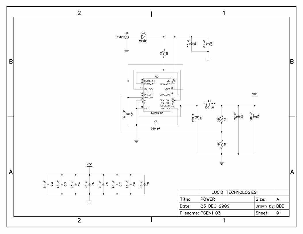
2.1 Power SupplySchematic sheet 1 (Appendix I) shows the power supply circuitry. D2 isolates the 9VDC
wall transformer from the PGEN-1. All PGEN-1 circuitry runs on +5V, which is provided by U3, a78S40 universal switching regulator subsystem. It is the core of a high efficiency step-downregulator capable of accepting a wide range of input voltages. The regulator is designed to deliver+5VDC at up to 100 mA of current. Ground and +5V test points are provided on the circuit board -see Appendix H.
Bypass capacitors C12-C19 (0.1 uFd) are located near integrated circuits aross the board.
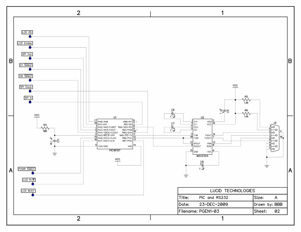
2.2 Microcontroller and RS-232 Serial PortThe PIC16F87 microcontroller, or PIC for short, is designated as U1 on sheet 2 of the
schematics. The PIC has 4096 words of flash program memory, 368 bytes of data memory (RAM),256 bytes of EEPROM memory, a 16-bit timer with prescaler (TMR1), an internal clock oscillator,a universal asynchronous receiver transmitter (UART), and 16 multi-functional input/output (I/O)lines. Lucid Technologies firmware is programmed in the PIC’s flash memory. The PIC’s internaloscillator is programmed to operate at 4 MHz.
The RS-232 serial port connector (J2) is described in detail in Appendix E. U2 is aMAX232A, 5V-powered RS-232 interface with two drivers and two receivers. One receiver/driverpair handles RS-232 data to/from the PGEN-1. The other receiver/driver pair receives RTS andsends it back to the host as CTS. RTS is also routed to the RB6 input on the PIC.
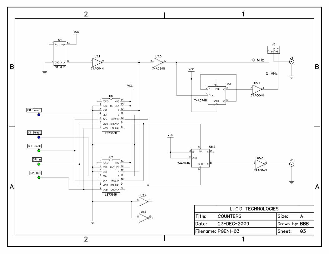
2.3 Clock and countersThe 10 MHz frequency reference for the PGEN-1, shown on schematic sheet 3, is a stable
TTL crystal clock oscillator (U4). Flip-flop U8.1 is used to divide the 10 MHz reference clock bytwo to produce a 5 MHz clock. Both 10 and 5 MHz clocks are routed to header J3 where either canbe connected via jumper to optional output connector J4.
The counters that give the Digital Pulse Generator its huge dynamic range are U6 and U7.These are LS7366R 32-bit quadrature counters with serial peripheral interface (SPI). U6 countsdown the logic-0 portion of the output and U7 counts down the logic-1 portion. The chips areprogrammed to operate in the non-quadrature single-cycle downcounter mode. In this mode the chipcounts down to zero at which point it pulses the DFLAG output low (for one 10 MHz clock cycle)then waits until the INDEX input goes low. When INDEX goes low the chip reloads the counterand begins to count down. By connecting the DFLAG output on each chip to the INDEX input onthe other chip it insures that only one chip is active at any time. When the logic-0 downcounter (U6)reaches zero it pulses its DFLAG output which sets the output flip-flop (U8.2) and reloads the logic-1 downcounter. The logic-1 downcounter (U7) then counts down to zero at which time it pulses itsDFLAG output which clears the output flip-flop (U8.2) and reloads the logic-0 downcounter foranother cycle. The PIC has to program the counters each time a setting changes, but onceprogrammed the counters will automatically generate the output pulse train.
2.4 LCD interface
(C) Lucid Technologies 4
PGEN Digital Pulse Generator
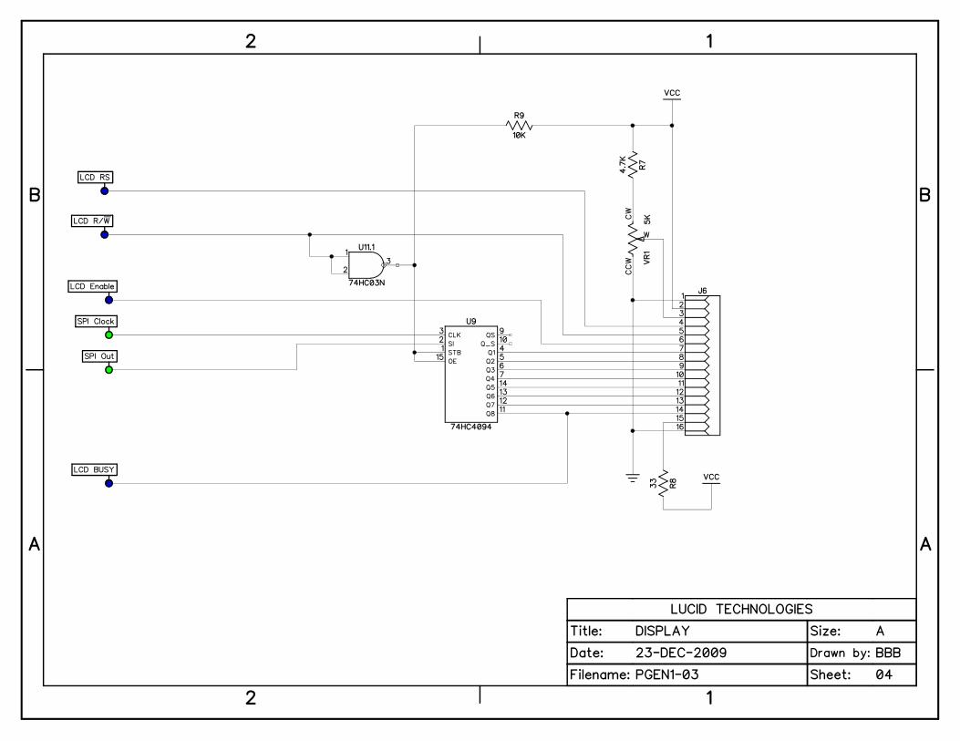
Liquid Crystal Display (LCD) modules compatible with the PGEN-1 circuit board are shownin Appendix C. These two-line by 16-character LCD modules have an 8-bit parallel interface with 4control lines. However the PIC is already using most of its I/O pins for RS-232 and SPI. Fortunatelyan 8-bit parallel output port can be connected to the SPI bus using the 74HC4094 (8-bit serial-to-parallel latch with tri-state outputs). As shown on schematic page 4, the LCD module interface isreduced to the already existing SPI bus plus 4 control lines.
The contrast of the liquid crystal display is controlled by potentiometer VR1. The LCDmodule is illuminated by LED back-lights. Resistor R8 limits the current to the LED back-lights.
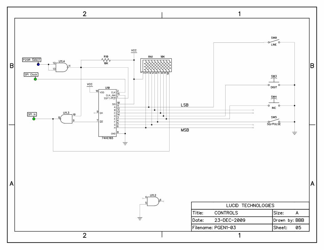
2.5 Shift Register InputsAn 8-bit parallel input-port was implemented with two NAND gates and a 74HC165 8-bit
parallel-input/serial-output shift register. Schematic sheet 5 shows the circuit. Parallel load of theshift register occurs when the P2SIR_Select signal goes low. Data is clocked out of the shift registerby the SPI_Clock signal. The inverted output is used because the shift register data is inverted againby the open-drain NAND gate (U11.3). An open-drain output is required because SPI_In is a wire-OR’ed signal.
The standard Digital Pulse Generator software uses only four of the eight parallel inputs.
3.0 Software Description
3.1 Assembler source codeThe assembly language source code for the standard Digital Pulse Generator is included with
the kit. The source code is well commented and highly modular. If you know PIC assemblylanguage it should be easy to understand. If you want to learn more about PIC programming and thefree Microchip Assembler (MPASM) consult some of the excellent resources on the Microchip website (see Appendix G for the URL).
The source code begins with several blocks of comments and equates. The comments, linesthat begin with a semicolon, are explanatory text that don’t generate any assembly code. Equates associate understandable names with fixed numeric values. For example the decimal value 103 isused to set the UART to 2400 baud, this value is given a more understandable name via the equate:BD2400 equ D'103'
The first block, PIC16F87 HARDWARE SETUP, has definitions of the PIC’s I/O pins,memory addresses, and equates for baud rate settings. This is followed by comment blocks about theLCD display, LS7366R counter chips, and 74HC165 inputs. The next block is equates assigningnames to the values for several ASCII characters.
The next three blocks are Assembler Directives, Variable Definitions, and Macros. TheAssembler Directives tell the MPASM assembler to generate code for the PIC16F87 in INHX8Mformat and what values to place in the Configuration Registers. The Variable Definitions reservememory registers for use by the program. For example, a serial receive subroutine will loop untileight bits are received; the bits received are counted in a variable called “bitcnt”. The following linetells the assembler to reserve one byte with the name “bitcnt”. bitcnt res 1 ; bit countMacros assign names to short blocks of code. The entire short block of code is inserted into theprogram wherever the macro’s name is found in the op-code column.
(C) Lucid Technologies 5
PGEN Digital Pulse Generator
3.2 InterruptsThe next part of the source code is the interrupt service routine. Only one interrupt is active
in the standard Digital Pulse Generator software, that is the Timer 1 (TMR1) overflow interrupt.The TMR1 prescaler clocks the 16-bit counter at 250 kHz which produces an overflow interruptevery 262 milliseconds (3.815 Hz). The interrupt service routine clears the interrupt flag andincrements the Timer 1 overflow counter (tmr1ofc) variable.
3.3 SubroutinesThe subroutines come next in the source code. The subroutines are well documented and
should be easy to follow for anyone who is familiar with PIC assembly language. The subroutinesare divided into six groups.
1) General Subroutines, such as data conversion; hex to ascii, ascii to hex, delays, etc.2) UART Subroutines, such as setting baud rates, transmitting and receiving bytes, etc.3) Synchronous Serial Port Subroutines handle the low level SPI data exchanges with the
LCD display, counter chips, and shift register inputs. 4) 32-bit Math Subroutines are required for the 32-bit counter chips. These subroutines
provide 32-bit add, subtract, multiply, divide, binary to BCD, and BCD to binary.5) LCD Module Interface Subroutines format data for display and coordinate the LCD’s
unique control lines with SPI output.6) Pulse Generator Data Manipulation Subroutines parse ASCII input strings from the host,
keep counter chip values within valid ranges, and swap data between 32-bit pseudo registers.
3.4 Main ProgramThe power on reset initialization code begins at the MAIN label. The internal oscillator is set
to 4 MHz, the direction of the I/O ports is set, the TMR1 overflow interrupt is set to 3.815 Hz, thecounter chips and LCD display are initialized, the start-up message is displayed and the TMR1overflow interrupt is enabled.
The label LOOP is the top of the main program loop. The program reads RB6 to see if RTSis ON, which means a computer is connected to the RS-232 serial port (J2). If RTS is ON thenprogram control jumps to label HOST_COM. Host communications is discussed in the next section.The program then reads and stores the input shift register byte. If there is no change in the frontpanel switches since they were last read the program jumps back to LOOP. If any switch haschanged the program reacts to the change, updates the counter chips and display if required, thenjumps back to LOOP.
3.5 Firmware modificationsModification of the Digital Pulse Generator firmware should only be attempted by someone
who is an expert in assembly language programming and possesses a PIC programmer. That beingsaid, for the knowledgeable, the original firmware provides well documented subroutines andexamples from which to learn. An easy way to try out new routines is to use option 6 on the hostcommunications menu. The jump to this option routine is already coded but the routine only consistof a jump back to the host communication mode.
(C) Lucid Technologies 6
PGEN Digital Pulse Generator
4.0 OperationWhen power is applied to the Digital Pulse Generator both counters are initialized to 0.5
milliseconds. The LCD display will show “LUCID TECH. Firmware XXX"; where XXX is theversion number of the installed firmware. After four seconds the display will change to that of theselected mode. See the front panel switch labels in Appendix D.
4.1 Pulse Mode OperationPulse mode is entered by placing the mode select switch in the PULSE position. The initial
display will be:1=0000.5000ms0=0000.5000ms
This display is telling one that the pulse width (logic-1) is 0.5ms and the pulse spacing (logic-0) is0.5ms. The LCD cursor will be on the first digit of the time value in the line chosen by the LINEselect switch. The cursor is moved one digit to the right by pressing the ADV (digit advance)pushbutton. The cursor will move from the seconds (left-most) to the hundreds-of-nanoseconds(right-most) position as the ADV pushbutton is depressed. When the cursor is on the right-mostdigit the next depression of ADV will move the cursor to the left-most digit on the same line.Toggling the LINE select switch will move the cursor to the same digit position on the other line.
The value under the cursor can be incremented by pressing the INC pushbutton. Values wraparound from 9 to 0 without a carry to the next higher digit. Whenever the INC pushbutton isdepressed the output waveform (OUT) changes to reflect the values shown on the display. The otherswitches all change the display but do not change the output waveform.
For example, a one millisecond pulse repeated once a second would be set as:1=0001.0000ms0=0999.0000ms
4.2 Square Mode OperationSquare mode is entered by placing the mode select switch in the SQUARE position. The
initial display will be:P=00001.0000msF=0001000.00Hz
This display is telling one that the Period is 1.0ms and the pulse Frequency is 1000 Hz. The LCDcursor will be on the first digit of the Frequency value; the LINE select switch has no effect in thismode. The ADV pushbutton functions the same way it does in the PULSE mode. The value underthe cursor can be incremented by pressing the INC pushbutton. Because the SQUARE modeproduces a square wave (50% duty factor) the minimum change in period is 200ns, 100ns for logic-1 and 100ns for logic-0. Because of the discrete step size not every frequency value is attainable.Every time the INC pushbutton is depressed the Digital Pulse Generator will compute the attainablefrequency closest to the new setting and update the counters and display to the computed value.
Note that the counter values that determine the output waveform are only changed when theINC pushbutton is pressed. Changing from one mode to another does not change the outputwaveform. In fact, changing modes from Pulse to Square is a convenient way to see the overallperiod of a waveform and its pulse repetition frequency. Consider the example from Section 4.1, aone millisecond pulse repeated once a second. In Pulse mode this would be set as follows.
1=0001.0000ms
(C) Lucid Technologies 7

PGEN Digital Pulse Generator
0=0999.0000msToggling to mode to Square would change the display to the following without changing the output.
P=01000.0000msF=0000001.00Hz
4.3 Host Communication ModeHost communication mode is entered by connecting an RS-232 cable between the Digital
Pulse Generator and the COM port of a host computer. A terminal program must be operating on the host for communication with the Digital Pulse Generator (see Appendix F). When the Digital PulseGenerator senses an RS-232 connection at J2 it tries to synchronize baud rates with the host. TheDigital Pulse Generator waits to receive a Return (Enter) character at 1200 baud. If it receives anyother character (such as a Return at another baud rate) it doubles its own baud rate and waits foranother Return at the new baud rate. If it reaches 19200 baud without receiving a Return it cyclesback to 1200 baud. To synchronize the Digital Pulse Generator with the host’s baud rate one simplyneeds to press Return (Enter) repeatedly until the Digital Pulse Generator sends the menu screen.
Digital Pulse Generator, Firmware 2.03 (C) Lucid Technologies 20110 Set low (0) time1 Set high (1) time2 Square wave3 Show settings4 Update counters5 Store powerup settings6 RC servoC Command lineX Exit?
Menu options are selected by typing the corresponding single number or character, any otherentries will be ignored and the menu will be displayed again. In the following examples the text sentby the Digital Pulse Generator is in italics, the text entered by the user is regular bold.
Time values are entered in microseconds or milliseconds. Microseconds are specified byentering the number with a u or U suffix. Milliseconds are specified with an m or M suffix.Frequency values are entered in Hertz with an h or H suffix.
0 Set low (0) time This option allows one to set the logic-0 or pulse spacing time. In the example shown here logic-0 isset to 9.25 milliseconds. The output waveform will not be changed until option 4 is selected.
?0Low time = 9.25m
1 Set high (1) time This option allows one to set the logic-1 or pulse width time. In the example shown here logic-1 isset to 750 microseconds. The output waveform will not be changed until option 4 is selected.
(C) Lucid Technologies 8
PGEN Digital Pulse Generator
?1High time = 750u
2 Square wave This option allows one to specify the frequency of a square wave. In the example shown here thespecified frequency is 2 kiloHertz. The Digital Pulse Generator will compute the frequency closestto the specified frequency. The actual frequency can be seen by selecting option 3. The outputwaveform will not be changed until option 4 is selected.
?2Frequency = 2000h
3 Show settings This option allows one to see the specified settings. The settings shown here are internallyconsistent but are not related to other examples shown in this manual.
?3Low time = 10.0000 millisecondsHigh time = 0.2499 millisecondsPeriod = 10.2499 millisecondsFrequency = 97.56 Hz
4 Update counters This option updates the logic-1 and logic-0 counters simultaneously - or as close to simultaneous asis possible addressing two SPI peripheral chips.
?4 Ok
5 Store powerup settings This option writes the current logic-0 and logic-1 pulse settings to the PIC16F87's internalEEPROM. When power is applied to the Digital Pulse Generator reads these values from theEEPROM and uses them to initialize the counters.
?5 Ok
6 RC servo This option configures the output pulse train for control of a Radio Control (RC) servo. RC servosrotate in response to a variable pulse width signal. The pulse width begins at 1.5 milliseconds whichcorresponds to the center of rotation. The minimum and maximum pulse widths for this routine are0.86 and 2.14 milliseconds respectively. The logic-0 or pulse spacing time is fixed at 28.5milliseconds. Pressing the l or L key decreases the pulse width causing the RC servo to rotate left; ror R increases the pulse width causing the RC servo to rotate right. The decrease/increase step sizeis 10 microseconds. Pressing the escape key returns the Host menu screen. In the example shownhere the L key was pressed two times.
?5Enter L, R, ESCape to abort.1.501.491.48
(C) Lucid Technologies 9
PGEN Digital Pulse Generator
X Exit This option terminates the Host communication mode and returns to the mode set on the modeselect switch.
?xDisconnect RS-232 cable.
C Command lineThe command line interface can be used in two ways. First, it can be used from a terminal
program for manual input without displaying the entire main menu. Second, it can function as thecontrol interface for a custom computer program on the host. When writing a computer program tointerface with the PGEN the program should monitor the characters received from the PGEN until itsees the ‘?’ character which is the input prompt of the Main Menu. The program should then send a‘C’ character to the PGEN to place it in command line mode. The program should send Onecommand at a time after receiving the ‘>’ prompt.
Each command is specified by a single ascii ‘command character’ sent to the PGENfollowing the ‘>’ prompt. Command characters may be lower or upper case, but are always echoedas upper case. All characters sent to the PGEN, except (CR), are echoed back to the host. Forcommands that require data, such as setting pulse times or frequency, the data must follow thecommand character and be terminated by a (CR). The acceptable formats for entry of pulse time andfrequency are identical to those used with the Main Menu – see section 4.3.
If the character sent to the PGEN following the prompt is not recognized as a validcommand character, a (NAK)(CR)(LF)> sequence will be sent to the host. If an error is found in the numeric data following a command, an error message will be sent - see section 4.4 - followed by a(NAK)(CR)(LF)> sequence. The command is ignored whenever a (NAK) is returned instead of an(ACK).
The command line interface uses only ascii characters. # = ascii numeric characterX = ascii alpha-numeric character( ) = single ascii byte[ / ] = one of two possible ascii bytes{error message} = one of several possible error messages
Setting the high (logic-1) time. Changes the internal register only, does not change the outputwaveform.Host à PGEN [h/H]####.####[m/M](CR) or [h/H]#######.#[u/U](CR)PGEN à Host (ACK)(CR)(LF)> or {error message}(NAK)(CR)(LF)>
Setting the low (logic-0) time. Changes the internal register only, does not change the outputwaveform.Host à PGEN [l/L]####.####[m/M](CR) or [l/L]#######.#[u/U](CR)PGEN à Host (ACK)(CR)(LF)> or {error message}(NAK)(CR)(LF)>
(C) Lucid Technologies 10
PGEN Digital Pulse Generator
Set the high (logic-1) and low (logic-0) times to produce a squarewave at the specified frequency.Changes the internal registers only, does not change the output waveform.Host à PGEN [f/F]#######.##[h/H](CR)PGEN à Host (ACK)(CR)(LF)> or {error message}(NAK)(CR)(LF)>
Write the current pulse settings in EEPROM for use as the initial settings at power up. Host à PGEN [p/P]PGEN à Host (ACK)(CR)(LF)>
Update the counters from the internal registers changing the output waveform. Host à PGEN [u/U]PGEN à Host (ACK)(CR)(LF)> Return the low (logic-0) time setting followed by the high (logic-1) time setting. Host à PGEN [s/S]PGEN à Host (ACK)####.####m,####.####m(CR)(LF)>
Return the firmware version. Host à PGEN [v/V]PGEN à Host (ACK)X.XX(CR)(LF)>
Quit. Host à PGEN (ESC)PGEN à Host (ACK)(Return to main menu)
4.4 Error MessagesThe routine that processes RS-232 inputs checks for obvious errors; if it finds an error the
input is ignored and an error message is displayed. Examples of the error messages are explainedbelow.
?0Low time = 12345.789012345m INPUT TOO LONG!
Here the user entered too many digits. The maximum number of alpha or numeric charactersallowed for any entry is sixteen.
?1High time = 750y INCORRECT UNIT CODE!
Here the user made a typographical error, entering ‘y’ as the unit code.
?1High time = 325h INCORRECT UNIT CODE!
Here the user should have entered a time in microseconds (u or U) or milliseconds (m or M) but heentered a frequency in Hertz.
?2
(C) Lucid Technologies 11
PGEN Digital Pulse Generator
Frequency = 16.6m INCORRECT UNIT CODE!Here the user should have entered a frequency in Hertz (h or H) but he entered a time inmilliseconds.
?1Low time = 20.25u INVALID FORMAT!
Here the user specified the time down to hundredths of a microsecond. This is beyond the resolutionof the PGEN because its minimum step size is 100 nanoseconds or 0.1 microsecond.
?2Frequency = 2ooh NOT AN ASCII NUMBER!
Here the user intended to enter two-hundred Hertz but he typed ohs instead of zeros.
(C) Lucid Technologies 12

PGEN Digital Pulse Generator
5.0 PGEN Circuit Board Assembly
5.1 PreparationYou will need the following tools:
> A low wattage soldering pencil, approximately 10 to 20 Watts. > Flux core solder wire, organic flux core preferred.
> Lead benders.> Lead/wire clippers.
Before beginning assemble, carefully check the PGEN circuit board for shorted orincomplete traces and confirm all parts against the list in Appendix A.
5.2 Assembly checklistCheck the value/type of each part as you assemble the board. Clip excess lead length from
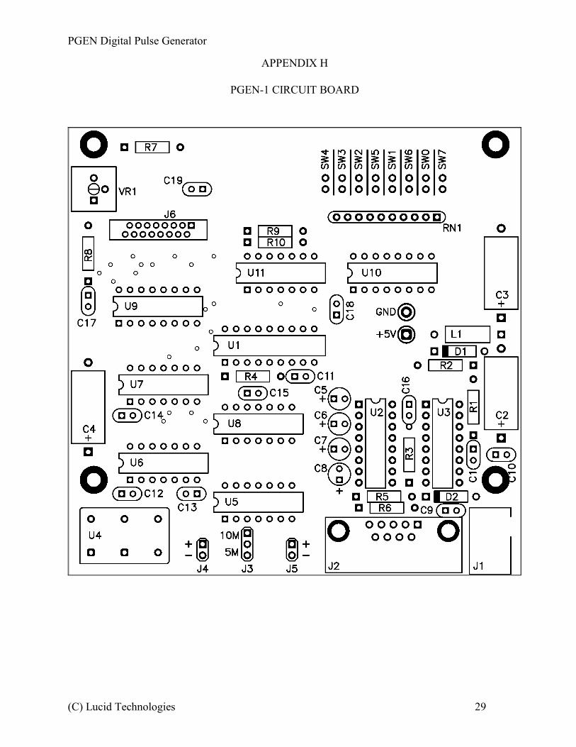
each component after it's soldered. See Appendix H for parts placement.
Insert and solder the low-profile sockets for:____ U1 18-pin DIP____ U2 16-pin DIP____ U3 16-pin DIP____ U5 14-pin DIP____ U6 14-pin DIP____ U7 14-pin DIP____ U8 14-pin DIP____ U9 16-pin DIP____ U10 16-pin DIP____ U11 14-pin DIP
Insert and solder the following components.____ R1 1.0 ohm, 0.25W, 5% (brown-black-gold-gold)____ R2 30K, 0.25W, 5% (orange-black-orange-gold)____ R3 10K, 0.25W, 5% (brown-black-orange-gold)____ R4 10K, 0.25W, 5% (brown-black-orange-gold)____ R5 1.1K, 0.25W, 5% (brown-brown-red-gold)____ R6 1.1K, 0.25W, 5% (brown-brown-red-gold)____ R7 4.7K, 0.25W, 5% (yellow-violet-red-gold)____ R8 33 ohm, 0.25W, 5% (orange-orange-black-gold)____ R9 10K, 0.25W, 5% (brown-black-orange-gold)____ R10 10K, 0.25W, 5% (brown-black-orange-gold)____ RN1 10k, 10-pin SIP, pin 1 goes in the square pad____ VR1 5k, trim pot____ D1 1N5818, banded end toward square pad____ D2 1N5818, banded end toward square pad____ C1 560 pFd, radial____ C2 47 uFd, axial, positive lead toward square pad____ C3 100 uFd, axial, positive lead toward square pad
(C) Lucid Technologies 13
PGEN Digital Pulse Generator
Figure 5.2 Orientation of J6
____ C4 100 uFd, axial, positive lead toward square pad____ C5 1.0 uFd, radial, positive lead toward square pad____ C6 1.0 uFd, radial, positive lead toward square pad____ C7 1.0 uFd, radial, positive lead toward square pad____ C8 1.0 uFd, radial, positive lead toward square pad____ C9 0.1 uFd, radial____ C10 0.1 uFd, radial____ C11 0.1 uFd, radial____ C12 0.1 uFd, radial____ C13 0.1 uFd, radial____ C14 0.1 uFd, radial____ C15 0.1 uFd, radial____ C16 0.1 uFd, radial____ C17 0.1 uFd, radial____ C18 0.1 uFd, radial____ C19 0.1 uFd, radial____ L1 150uH inductor (brown, green, brown)____ J1 DC power jack____ J2 DB9 female connector____ J3 3x1 jumper header____ U4 10 MHz clock
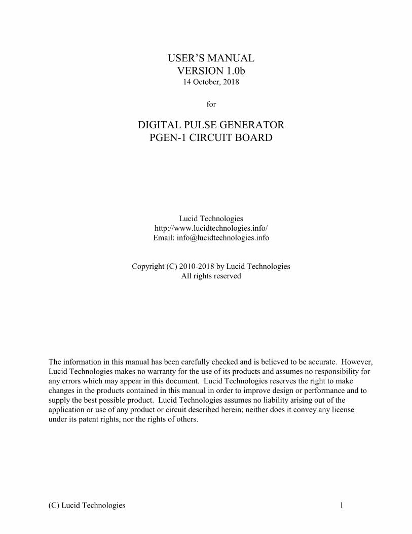
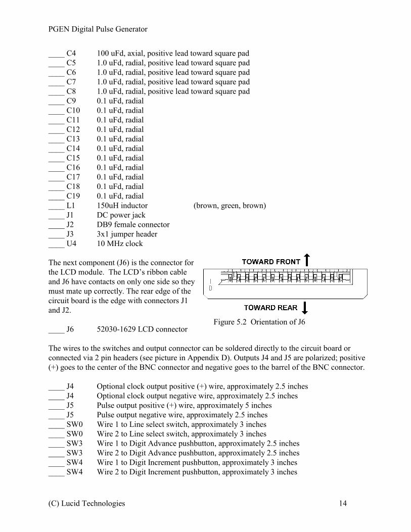
The next component (J6) is the connector forthe LCD module. The LCD’s ribbon cableand J6 have contacts on only one side so theymust mate up correctly. The rear edge of thecircuit board is the edge with connectors J1and J2.
____ J6 52030-1629 LCD connector
The wires to the switches and output connector can be soldered directly to the circuit board orconnected via 2 pin headers (see picture in Appendix D). Outputs J4 and J5 are polarized; positive(+) goes to the center of the BNC connector and negative goes to the barrel of the BNC connector.
____ J4 Optional clock output positive (+) wire, approximately 2.5 inches____ J4 Optional clock output negative wire, approximately 2.5 inches____ J5 Pulse output positive (+) wire, approximately 5 inches____ J5 Pulse output negative wire, approximately 2.5 inches____ SW0 Wire 1 to Line select switch, approximately 3 inches____ SW0 Wire 2 to Line select switch, approximately 3 inches____ SW3 Wire 1 to Digit Advance pushbutton, approximately 2.5 inches____ SW3 Wire 2 to Digit Advance pushbutton, approximately 2.5 inches____ SW4 Wire 1 to Digit Increment pushbutton, approximately 3 inches____ SW4 Wire 2 to Digit Increment pushbutton, approximately 3 inches
(C) Lucid Technologies 14
PGEN Digital Pulse Generator
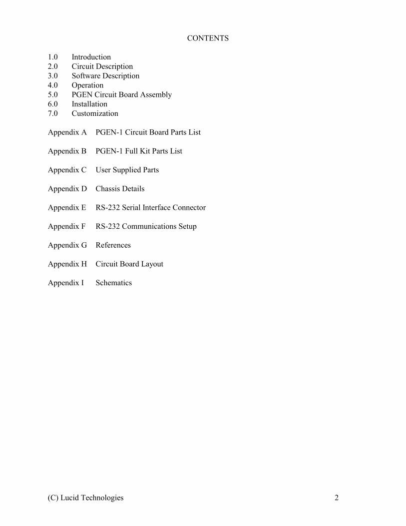
Figure 6.1 LCD mounting hardware
____ SW5 Wire 1 to Mode select switch, approximately 3 inches____ SW5 Wire 2 to Mode select switch, approximately 3 inches
The last construction step is to clean the board. If you used organic core solder just rinse the boardin warm water. If you used acid core solder try scrubbing it with an old toothbrush and rubbingalcohol.
5.3 Circuit Board CheckoutYou will need a multimeter and oscilloscope or logic probe to check out the PGEN circuitry.
Place the PGEN circuit board on an insulating surface. DO NOT install the integrated circuits yet. Attach the negative lead of your voltmeter to the ground test point. Plug-in your 9V wall
transformer and connect it to J1 on the PGEN. The supply voltage should measure at least 8VDCon the positive lead of C2 (47 uFd). Disconnect the wall transformer at J1 then insert the 78S40 insocket U3. Reconnect the wall transformer then measure the voltage at the +5V test point. Thevoltage should be between 4.9 and 5.1 volts.
If there is a problem, disconnect the wall transformer and inspect the PGEN circuit board. Be sure the 78S40 is not backwards in the socket. Check that diodes D1, D2 and capacitors C2, C3,C4 are not installed backwards. Refer to schematic page 1 and check the value of all other resistorsand capacitors attached to U3. Correct any errors and check +5V again.
With the wall transformer disconnected install U5 (74AC04) and U8 (74AC74). Connect thewall transformer, then use your oscilloscope or logic probe to check for the proper frequency squarewaves on the pins of J3; 10 MHz on the forward pin and 5 MHz on the rear pin. If both signals areabsent check that U4 and U5 are not backwards. If 10 MHz is present but not 5 MHz check that U8is not backwards.
Disconnect the wall transformer again, then insert the remainder of the integrated circuits intheir sockets. The remainder of the Digital Pulse Generator checkout must wait until the front panelcontrols and display are connected.
6.0 Installation
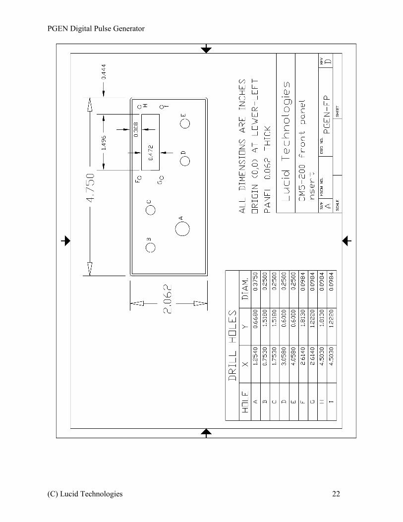
6.1 Prepare the Front PanelAssuming you are using the suggested
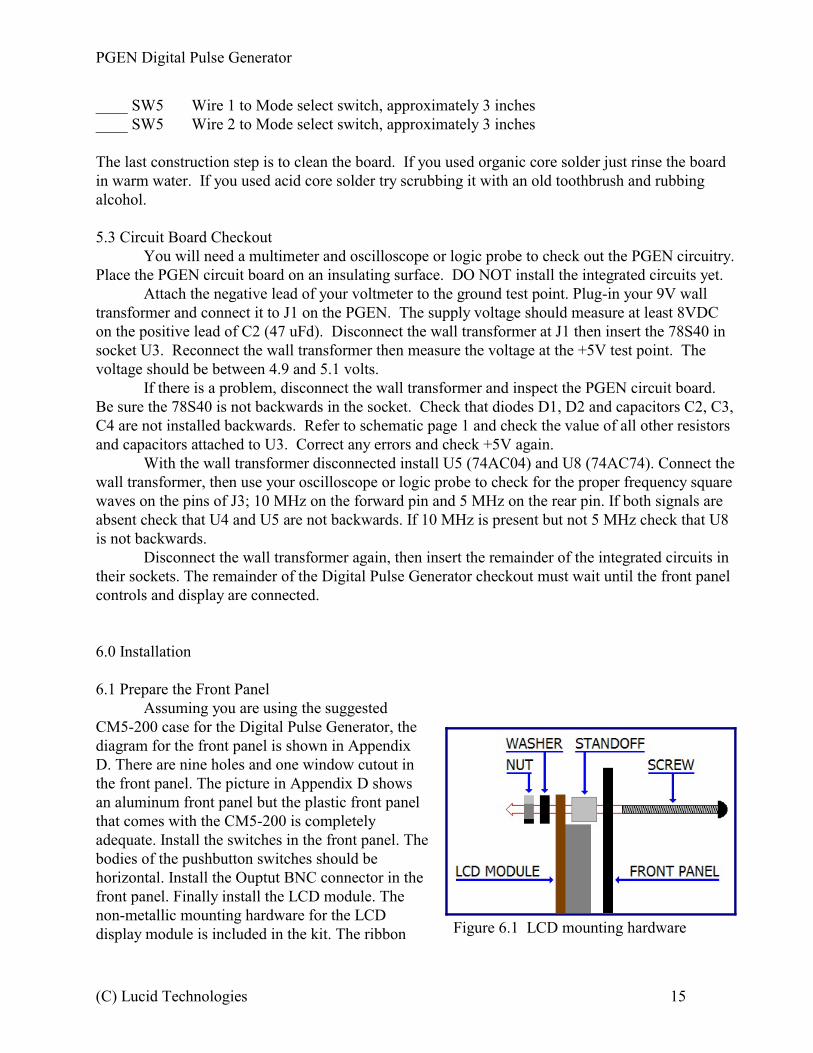
CM5-200 case for the Digital Pulse Generator, thediagram for the front panel is shown in AppendixD. There are nine holes and one window cutout inthe front panel. The picture in Appendix D showsan aluminum front panel but the plastic front panelthat comes with the CM5-200 is completelyadequate. Install the switches in the front panel. Thebodies of the pushbutton switches should behorizontal. Install the Ouptut BNC connector in thefront panel. Finally install the LCD module. Thenon-metallic mounting hardware for the LCDdisplay module is included in the kit. The ribbon
(C) Lucid Technologies 15
PGEN Digital Pulse Generator
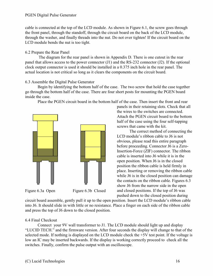
Figure 6.3a Open Figure 6.3b Closed
cable is connected at the top of the LCD module. As shown in Figure 6.1, the screw goes throughthe front panel, through the standoff, through the circuit board on the back of the LCD module,through the washer, and finally threads into the nut. Do not over tighten! If the circuit board on theLCD module bends the nut is too tight.
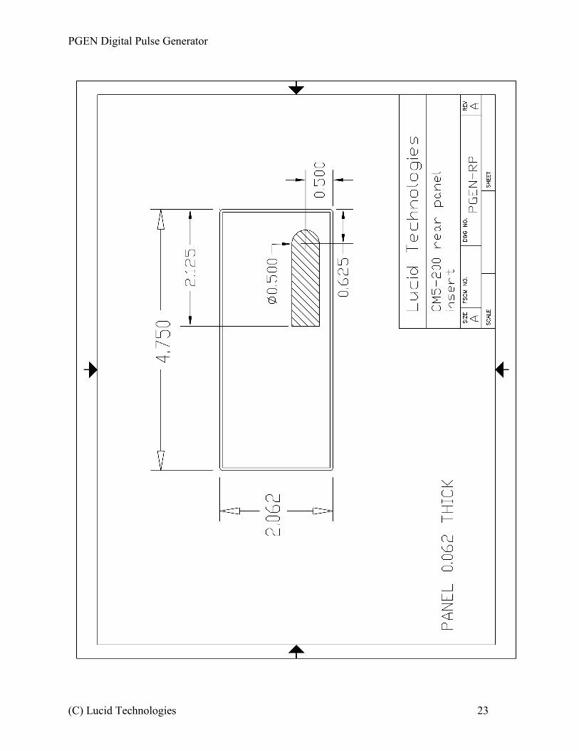
6.2 Prepare the Rear Panel The diagram for the rear panel is shown in Appendix D. There is one cutout in the rear
panel that allows access to the power connector (J1) and the RS-232 connector (J2). If the optionalclock output connector is used it should be installed in a 0.375 inch hole in the rear panel. Theactual location is not critical so long as it clears the components on the circuit board.
6.3 Assemble the Digital Pulse GeneratorBegin by identifying the bottom half of the case. The two screw that hold the case together
go through the bottom half of the case. There are four short posts for mounting the PGEN boardinside the case.
Place the PGEN circuit board in the bottom half of the case. Then insert the front and rearpanels in their retaining slots. Check that allthe wires to the switches are connected.Attach the PGEN circuit board to the bottomhalf of the case using the four self-tappingscrews that came with the kit.
The correct method of connecting theLCD module’s ribbon cable to J6 is notobvious, please read this entire paragraphbefore proceeding. Connector J6 is a Zero-Insertion-Force (ZIF) connector. The ribboncable is inserted into J6 while it is in theopen position. When J6 is in the closedposition the ribbon cable is held firmly inplace. Inserting or removing the ribbon cablewhile J6 is in the closed position can damagethe contacts on the ribbon cable. Figures 6.3show J6 from the narrow side in the openand closed positions. If the top of J6 waspushed down to the closed position during
circuit board assemble, gently pull it up to the open position. Insert the LCD module’s ribbon cableinto J6. It should slide in with little or no resistance. Place a finger on each side of the ribbon cableand press the top of J6 down to the closed position.
6.4 Final CheckoutConnect your 9V wall transformer to J1. The LCD module should light up and display
“LUCID TECH.” and the firmware version. After four seconds the display will change to that of theselected mode. If nothing is displayed on the LCD module check the +5V test point. If the voltage islow an IC may be inserted backwards. If the display is working correctly proceed to check all theswitches. Finally, confirm the pulse output with an oscilloscope.
(C) Lucid Technologies 16

PGEN Digital Pulse Generator
7.0 CustomizationThe PGEN circuit board does not need to be installed in the CM5-200 case suggested by this
manual. That case’s small front panel limits the number of controls. In a larger case there could be,for example, two switches to move the cursor left and right; or two buttons to increment anddecrement the value at the cursor. The suggested configuration uses only four inputs from the 8-bitparallel input-port leaving four more inputs available. Obviously adding more controls will requirechanges in the firmware.
(C) Lucid Technologies 17
PGEN Digital Pulse Generator
APPENDIX A
PGEN-1 CIRCUIT BOARD PARTS LIST
Quantity Part Reference==================================================================== 1 560pF, 35V, radial C1 1 47uF, 35V, axial C2 2 100uF, 25V, axial C3,C4 4 1.0uF, 50V, radial C5 - C8 11 0.1uF, 35V, radial C9 - C19 1 1.0 ohm, 0.25W, 5% R1 (brown-black-gold-gold) 1 30K, 0.25W, 5% R2 (orange-black-orange-gold) 4 10K, 0.25W, 5% R3,R4,R9,R10 (brown-black-orange-gold) 2 1.1K, 0.25W, 5% R5,R6 (brown-brown-red-gold) 1 4.7K, 0.25W, 5% R7 (yellow-violet-red-gold) 1 33 ohm, 0.25W, 5% R8 (orange-orange-black-gold) 1 10K, 10-SIP, pin-1 common RN1 1 5K trim pot VR1 2 1N5818, 30V D1,D2 1 PIC16F87-I/P, 18-DIP U1 1 MAX232CPE, 16-DIP U2 1 78S40, 16-DIP U3 1 10MHz clock, 14-DIP U4 1 74AC04, 14-DIP U5 2 LS7366R, 14-DIP U6,U7 1 74AC74, 14-DIP U8 1 74HC4094, 16-DIP U9 1 74HC165, 16-DIP U10 1 74HC03, 14-DIP U11 1 18-DIP socket U1 4 16-DIP socket U2,U3,U9,U10 5 14-DIP socket U5 - U8,U11 1 DC power jack J1 1 DB9 female connector J2 1 3x1 jumper header J3 2 2x1 output header J4,J5 1 52030-1629 LCD connector J6 1 150uH L1 1 PGEN-1 circuit board 1 Jumper
(C) Lucid Technologies 18

PGEN Digital Pulse Generator
APPENDIX B
PGEN-1 FULL KIT PARTS LIST
The full PGEN-1 kit supplied by Lucid Technologies includes all the circuit board partsshown in Appendix A plus the following:
Four self-tapping screws for mounting the printed circuit board in a plastic case.
LCD module mounting hardware -Four screws, #2, 0.5 inch long, nylonFour nuts, #2, nylonFour standoffs, 4 mm long, nylonFour washers, plastic
The PGEN-1 kit sold by Lucid Technologies does not include all the parts necessary for afully functional Digital Pulse Generator. Lucid Technologies recommends the case, switches anddisplay listed in Appendix C.
(C) Lucid Technologies 19
PGEN Digital Pulse Generator
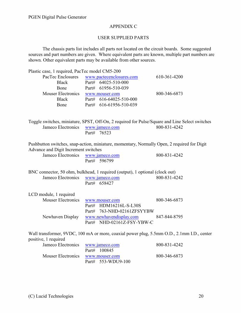
APPENDIX C
USER SUPPLIED PARTS
The chassis parts list includes all parts not located on the circuit boards. Some suggestedsources and part numbers are given. Where equivalent parts are known, multiple part numbers areshown. Other equivalent parts may be available from other sources.
Plastic case, 1 required, PacTec model CM5-200PacTec Enclosures www.pactecenclosures.com 610-361-4200
Black Part# 64025-510-000Bone Part# 61956-510-039
Mouser Electronics www.mouser.com 800-346-6873Black Part# 616-64025-510-000Bone Part# 616-61956-510-039
Toggle switches, miniature, SPST, Off-On, 2 required for Pulse/Square and Line Select switchesJameco Electronics www.jameco.com 800-831-4242
Part# 76523
Pushbutton switches, snap-action, miniature, momentary, Normally Open, 2 required for DigitAdvance and Digit Increment switches
Jameco Electronics www.jameco.com 800-831-4242Part# 596799
BNC connector, 50 ohm, bulkhead, 1 required (output), 1 optional (clock out)Jameco Electronics www.jameco.com 800-831-4242
Part# 658427
LCD module, 1 requiredMouser Electronics www.mouser.com 800-346-6873
Part# HDM16216L-S-L30SPart# 763-NHD-02161ZFSYYBW
Newhaven Display www.newhavendisplay.com 847-844-8795Part# NHD-02161Z-FSY-YBW-C
Wall transformer, 9VDC, 100 mA or more, coaxial power plug, 5.5mm O.D., 2.1mm I.D., centerpositive, 1 required
Jameco Electronics www.jameco.com 800-831-4242Part# 100845
Mouser Electronics www.mouser.com 800-346-6873Part# 553-WDU9-100
(C) Lucid Technologies 20
PGEN Digital Pulse Generator
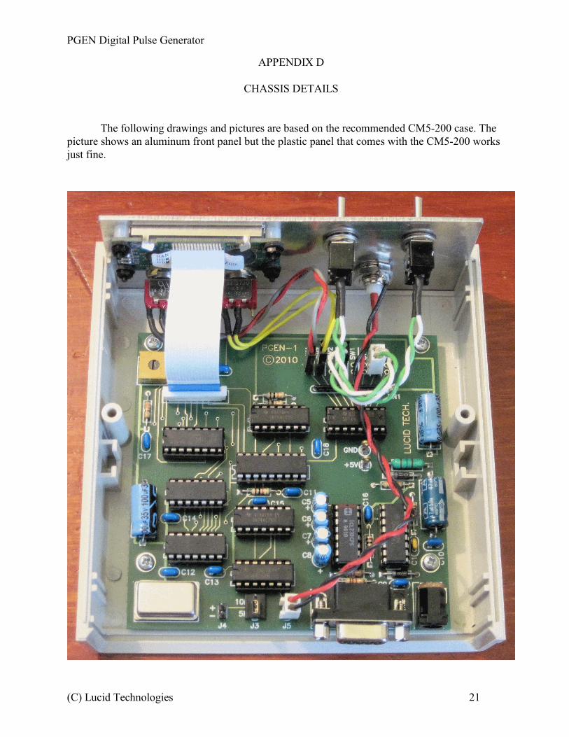
APPENDIX D
CHASSIS DETAILS
The following drawings and pictures are based on the recommended CM5-200 case. Thepicture shows an aluminum front panel but the plastic panel that comes with the CM5-200 worksjust fine.
(C) Lucid Technologies 21
PGEN Digital Pulse Generator
(C) Lucid Technologies 22
PGEN Digital Pulse Generator
(C) Lucid Technologies 23
PGEN Digital Pulse Generator
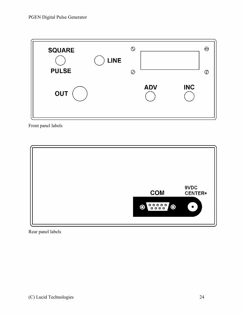
Front panel labels
Rear panel labels
(C) Lucid Technologies 24
PGEN Digital Pulse Generator
APPENDIX E
RS-232 SERIAL INTERFACE CONNECTOR
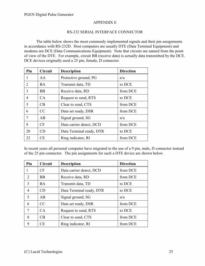
The table below shows the most commonly implemented signals and their pin assignmentsin accordance with RS-232D. Host computers are usually DTE (Data Terminal Equipment) andmodems are DCE (Data Communications Equipment). Note that circuits are named from the pointof view of the DTE. For example, circuit BB (receive data) is actually data transmitted by the DCE. DCE devices originally used a 25 pin, female, D connector.
Pin Circuit Description Direction
1 AA Protective ground, PG n/a
2 BA Transmit data, TD to DCE
3 BB Receive data, RD from DCE
4 CA Request to send, RTS to DCE
5 CB Clear to send, CTS from DCE
6 CC Data set ready, DSR from DCE
7 AB Signal ground, SG n/a
8 CF Data carrier detect, DCD from DCE
20 CD Data Terminal ready, DTR to DCE
22 CE Ring indicator, RI from DCE
In recent years all personal computer have migrated to the use of a 9 pin, male, D connector insteadof the 25 pin connector. The pin assignments for such a DTE device are shown below.
Pin Circuit Description Direction
1 CF Data carrier detect, DCD from DCE
2 BB Receive data, RD from DCE
3 BA Transmit data, TD to DCE
4 CD Data Terminal ready, DTR to DCE
5 AB Signal ground, SG n/a
6 CC Data set ready, DSR from DCE
7 CA Request to send, RTS to DCE
8 CB Clear to send, CTS from DCE
9 CE Ring indicator, RI from DCE
(C) Lucid Technologies 25
PGEN Digital Pulse Generator
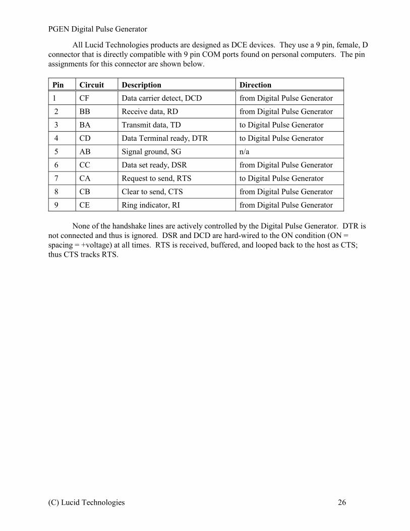
All Lucid Technologies products are designed as DCE devices. They use a 9 pin, female, Dconnector that is directly compatible with 9 pin COM ports found on personal computers. The pinassignments for this connector are shown below.
Pin Circuit Description Direction
1 CF Data carrier detect, DCD from Digital Pulse Generator
2 BB Receive data, RD from Digital Pulse Generator
3 BA Transmit data, TD to Digital Pulse Generator
4 CD Data Terminal ready, DTR to Digital Pulse Generator
5 AB Signal ground, SG n/a
6 CC Data set ready, DSR from Digital Pulse Generator
7 CA Request to send, RTS to Digital Pulse Generator
8 CB Clear to send, CTS from Digital Pulse Generator
9 CE Ring indicator, RI from Digital Pulse Generator
None of the handshake lines are actively controlled by the Digital Pulse Generator. DTR isnot connected and thus is ignored. DSR and DCD are hard-wired to the ON condition (ON =spacing = +voltage) at all times. RTS is received, buffered, and looped back to the host as CTS;thus CTS tracks RTS.
(C) Lucid Technologies 26
PGEN Digital Pulse Generator
APPENDIX F
RS-232 COMMUNICATIONS SETUP
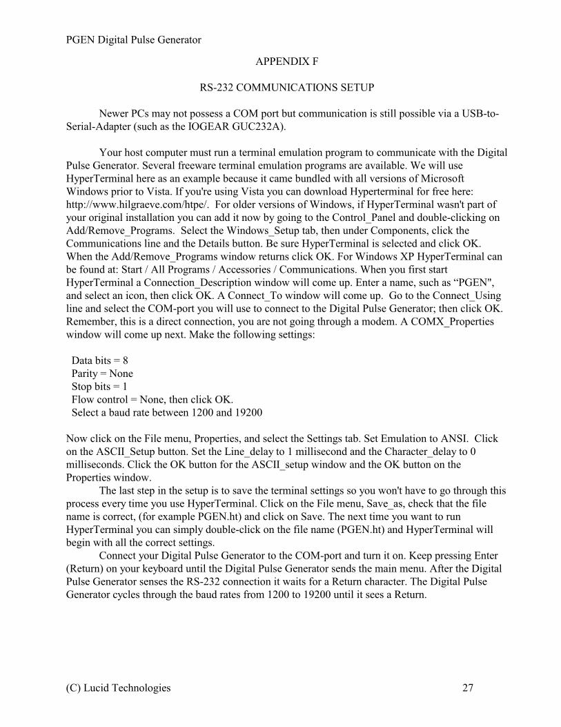
Newer PCs may not possess a COM port but communication is still possible via a USB-to-Serial-Adapter (such as the IOGEAR GUC232A).
Your host computer must run a terminal emulation program to communicate with the DigitalPulse Generator. Several freeware terminal emulation programs are available. We will useHyperTerminal here as an example because it came bundled with all versions of MicrosoftWindows prior to Vista. If you're using Vista you can download Hyperterminal for free here:http://www.hilgraeve.com/htpe/. For older versions of Windows, if HyperTerminal wasn't part ofyour original installation you can add it now by going to the Control_Panel and double-clicking onAdd/Remove_Programs. Select the Windows_Setup tab, then under Components, click theCommunications line and the Details button. Be sure HyperTerminal is selected and click OK.When the Add/Remove_Programs window returns click OK. For Windows XP HyperTerminal canbe found at: Start / All Programs / Accessories / Communications. When you first startHyperTerminal a Connection_Description window will come up. Enter a name, such as “PGEN",and select an icon, then click OK. A Connect_To window will come up. Go to the Connect_Usingline and select the COM-port you will use to connect to the Digital Pulse Generator; then click OK. Remember, this is a direct connection, you are not going through a modem. A COMX_Propertieswindow will come up next. Make the following settings:
Data bits = 8 Parity = None Stop bits = 1 Flow control = None, then click OK. Select a baud rate between 1200 and 19200
Now click on the File menu, Properties, and select the Settings tab. Set Emulation to ANSI. Clickon the ASCII_Setup button. Set the Line_delay to 1 millisecond and the Character_delay to 0milliseconds. Click the OK button for the ASCII_setup window and the OK button on theProperties window.
The last step in the setup is to save the terminal settings so you won't have to go through thisprocess every time you use HyperTerminal. Click on the File menu, Save_as, check that the filename is correct, (for example PGEN.ht) and click on Save. The next time you want to runHyperTerminal you can simply double-click on the file name (PGEN.ht) and HyperTerminal willbegin with all the correct settings.
Connect your Digital Pulse Generator to the COM-port and turn it on. Keep pressing Enter(Return) on your keyboard until the Digital Pulse Generator sends the main menu. After the DigitalPulse Generator senses the RS-232 connection it waits for a Return character. The Digital PulseGenerator cycles through the baud rates from 1200 to 19200 until it sees a Return.
(C) Lucid Technologies 27
PGEN Digital Pulse Generator
APPENDIX G
REFERENCES
Hantronix Inc. (www.hantronix.com)Data Sheet - HDM16216L-S, 16-character x 2-line liquid crystal display Module
LSI Computer Systems (www.lsicsi.com)Data Sheet - LS7366R, 32-bit quadrature counter with serial interface
Maxim (www.maxim-ic.com) Data Sheet - DS1305, Serial Alarm Real-Time Clock, REV: 070705
Microchip (www.microchip.com)PIC16F87/88 Data Sheet, DS30487C
National (www.national.com/analog)Data Sheet - LM78S40 Universal Switching Regulator Subsystem
Newhaven Display International (www.newhavendisplay.com)Data Sheet - NHD-02161Z-FSY-YBW-C, 16-character x 2-line liquid crystal display Module
On Semiconductor (www.onsemi.com)Application Note 920 - Theory and applications of the MC34063 and uA78S40 switching regulatorcontrol circuits
(C) Lucid Technologies 28
PGEN Digital Pulse Generator
APPENDIX H
PGEN-1 CIRCUIT BOARD
(C) Lucid Technologies 29
CLR
PR
CLR
PR

![PGEN: Novel Approach Sequential Circuit Generationdownloads.hindawi.com/archive/1996/068463.pdf · The PODEM algorithm [10] used for combina-tional circuit testing is transplanted](https://img.pdfslide.us/doc/110x75/5e889fefbf28cd219b763703/pgen-novel-approach-sequential-circuit-the-podem-algorithm-10-used-for-combina-tional.jpg)