Embed Size (px)
Citation preview
User’s and Programmer’s ReferenceVolume 2
One-Button Power Measurements
PSA and ESA Series Spectrum AnalyzersRefer to Volume 1 for core spectrum analyzer information.
This manual provides documentation for the following instruments:Agilent Technologies PSA Series
E4443A (3 Hz - 6.7 GHz)E4445A (3 Hz - 13.2 GHz)
E4440A (3 Hz - 26.5 GHz)E4447A (3 Hz - 42.98 GHz)E4446A (3 Hz - 44.0 GHz)E4448A (3 Hz - 50.0 GHz)
Agilent Technologies ESA-E SeriesE4402B (9 kHz - 3.0 GHz)
E4404B (9 kHz - 6.7 GHz)E4405B (9 kHz - 13.2 GHz)E4407B (9 kHz - 26.5 GHz)
Agilent Technologies ESA-L SeriesE4411B (9 kHz- 1.5 GHz)
E4403B (9 kHz - 3.0 GHz)E4408B (9 kHz - 26.5 GHz)
Manufacturing Part Number: E4440-90618Supersedes: E4440-90346
Printed in USA
June 2008
© Copyright 1999-2008 Agilent Technologies, Inc..
Legal InformationThe information contained in this document is subject to change without notice.
Agilent Technologies makes no warranty of any kind with regard to this material, including but not limited to, the implied warranties of merchantability and fitness for a particular purpose. Agilent Technologies shall not be liable for errors contained herein or for incidental or consequential damages in connection with the furnishing, performance, or use of this material.
Where to Find the Latest Information
Documentation is updated periodically.
• For the latest information about Agilent Technologies PSA Spectrum Analyzers, including firmware upgrades and application information, please visit the following Internet URL:
http://www.agilent.com/find/psa
• For the latest information about Agilent Technologies ESA Spectrum Analyzers, including firmware upgrades and application information, please visit the following Internet URL:
http://www.agilent.com/find/esa
• To receive the latest updates by email, subscribe to Agilent Email Updates:
http://www.agilent.com/find/emailupdates
• Information on preventing spectrum analyzer damage can be found at:
http://www.agilent.com/find/tips
2
ContentsTab
le of C
on
tents
1. Using This DocumentAbout the User’s and Programmer’s Information . . . . . . . . . . . . . . . . . . . . . . . . . . . . . . . . . . 24
What is in This Book. . . . . . . . . . . . . . . . . . . . . . . . . . . . . . . . . . . . . . . . . . . . . . . . . . . . . . . . 24Terms Used in This Book . . . . . . . . . . . . . . . . . . . . . . . . . . . . . . . . . . . . . . . . . . . . . . . . . . . . 25
2. One-Button Measurement FunctionsOne - Button Measurement Functions . . . . . . . . . . . . . . . . . . . . . . . . . . . . . . . . . . . . . . . . . . . 28Mode Setup (Spectrum Analysis Mode) . . . . . . . . . . . . . . . . . . . . . . . . . . . . . . . . . . . . . . . . . . 31
Radio Std . . . . . . . . . . . . . . . . . . . . . . . . . . . . . . . . . . . . . . . . . . . . . . . . . . . . . . . . . . . . . . . . . 31Radio Std Setup. . . . . . . . . . . . . . . . . . . . . . . . . . . . . . . . . . . . . . . . . . . . . . . . . . . . . . . . . . . . 43Retain Params. . . . . . . . . . . . . . . . . . . . . . . . . . . . . . . . . . . . . . . . . . . . . . . . . . . . . . . . . . . . . 45Enable All Measurements . . . . . . . . . . . . . . . . . . . . . . . . . . . . . . . . . . . . . . . . . . . . . . . . . . . 45Autorange of Power Setting (Remote command only). . . . . . . . . . . . . . . . . . . . . . . . . . . . . . 46
MEASURE (Spectrum Analysis Mode) . . . . . . . . . . . . . . . . . . . . . . . . . . . . . . . . . . . . . . . . . . 47Command Interactions: MEASure, CONFigure, FETCh, INITiate and READ . . . . . . . . . 48Current Measurement Query (Remote Command Only) . . . . . . . . . . . . . . . . . . . . . . . . . . . 51Test Current Results Against all Limits (Remote Command Only). . . . . . . . . . . . . . . . . . . 51Meas Off. . . . . . . . . . . . . . . . . . . . . . . . . . . . . . . . . . . . . . . . . . . . . . . . . . . . . . . . . . . . . . . . . . 52Channel Power . . . . . . . . . . . . . . . . . . . . . . . . . . . . . . . . . . . . . . . . . . . . . . . . . . . . . . . . . . . . 52Occupied BW . . . . . . . . . . . . . . . . . . . . . . . . . . . . . . . . . . . . . . . . . . . . . . . . . . . . . . . . . . . . . 55Adjacent Channel Power—ACP . . . . . . . . . . . . . . . . . . . . . . . . . . . . . . . . . . . . . . . . . . . . . . . 56Multi-Carrier Power . . . . . . . . . . . . . . . . . . . . . . . . . . . . . . . . . . . . . . . . . . . . . . . . . . . . . . . . 60Power Stat CCDF . . . . . . . . . . . . . . . . . . . . . . . . . . . . . . . . . . . . . . . . . . . . . . . . . . . . . . . . . . 62Harmonic Distortion . . . . . . . . . . . . . . . . . . . . . . . . . . . . . . . . . . . . . . . . . . . . . . . . . . . . . . . 65Burst Power . . . . . . . . . . . . . . . . . . . . . . . . . . . . . . . . . . . . . . . . . . . . . . . . . . . . . . . . . . . . . . 68Intermod (TOI) . . . . . . . . . . . . . . . . . . . . . . . . . . . . . . . . . . . . . . . . . . . . . . . . . . . . . . . . . . . . 71Spurious Emissions . . . . . . . . . . . . . . . . . . . . . . . . . . . . . . . . . . . . . . . . . . . . . . . . . . . . . . . . 72Spectrum Emission Mask . . . . . . . . . . . . . . . . . . . . . . . . . . . . . . . . . . . . . . . . . . . . . . . . . . . . 73
Meas Setup (Adjacent Channel Power—ACP) . . . . . . . . . . . . . . . . . . . . . . . . . . . . . . . . . . . . . 81Avg Number . . . . . . . . . . . . . . . . . . . . . . . . . . . . . . . . . . . . . . . . . . . . . . . . . . . . . . . . . . . . . . 81Avg Mode . . . . . . . . . . . . . . . . . . . . . . . . . . . . . . . . . . . . . . . . . . . . . . . . . . . . . . . . . . . . . . . . 82Chan Integ BW . . . . . . . . . . . . . . . . . . . . . . . . . . . . . . . . . . . . . . . . . . . . . . . . . . . . . . . . . . . . 82Offset/Limits . . . . . . . . . . . . . . . . . . . . . . . . . . . . . . . . . . . . . . . . . . . . . . . . . . . . . . . . . . . . . . 83Meas Type . . . . . . . . . . . . . . . . . . . . . . . . . . . . . . . . . . . . . . . . . . . . . . . . . . . . . . . . . . . . . . . . 87Optimize Ref Level . . . . . . . . . . . . . . . . . . . . . . . . . . . . . . . . . . . . . . . . . . . . . . . . . . . . . . . . . 88Method . . . . . . . . . . . . . . . . . . . . . . . . . . . . . . . . . . . . . . . . . . . . . . . . . . . . . . . . . . . . . . . . . . 88Total Pwr Ref . . . . . . . . . . . . . . . . . . . . . . . . . . . . . . . . . . . . . . . . . . . . . . . . . . . . . . . . . . . . . 91PSD Ref . . . . . . . . . . . . . . . . . . . . . . . . . . . . . . . . . . . . . . . . . . . . . . . . . . . . . . . . . . . . . . . . . . 92Limit Test . . . . . . . . . . . . . . . . . . . . . . . . . . . . . . . . . . . . . . . . . . . . . . . . . . . . . . . . . . . . . . . . 93RRC Filter . . . . . . . . . . . . . . . . . . . . . . . . . . . . . . . . . . . . . . . . . . . . . . . . . . . . . . . . . . . . . . . 93Filter Alpha . . . . . . . . . . . . . . . . . . . . . . . . . . . . . . . . . . . . . . . . . . . . . . . . . . . . . . . . . . . . . . 94Noise Correction . . . . . . . . . . . . . . . . . . . . . . . . . . . . . . . . . . . . . . . . . . . . . . . . . . . . . . . . . . . 94
Trace/View (ACP Measurement) . . . . . . . . . . . . . . . . . . . . . . . . . . . . . . . . . . . . . . . . . . . . . . . . 97Spectrum . . . . . . . . . . . . . . . . . . . . . . . . . . . . . . . . . . . . . . . . . . . . . . . . . . . . . . . . . . . . . . . . . 97Bar Graph . . . . . . . . . . . . . . . . . . . . . . . . . . . . . . . . . . . . . . . . . . . . . . . . . . . . . . . . . . . . . . . . 97Combined. . . . . . . . . . . . . . . . . . . . . . . . . . . . . . . . . . . . . . . . . . . . . . . . . . . . . . . . . . . . . . . . . 98Combined View Units . . . . . . . . . . . . . . . . . . . . . . . . . . . . . . . . . . . . . . . . . . . . . . . . . . . . . . . 98Trace . . . . . . . . . . . . . . . . . . . . . . . . . . . . . . . . . . . . . . . . . . . . . . . . . . . . . . . . . . . . . . . . . . . . 98
Meas Setup (Burst Power) . . . . . . . . . . . . . . . . . . . . . . . . . . . . . . . . . . . . . . . . . . . . . . . . . . . . . 99
3
ContentsTa
ble
of
Co
nte
nts
Avg Number . . . . . . . . . . . . . . . . . . . . . . . . . . . . . . . . . . . . . . . . . . . . . . . . . . . . . . . . . . . . . . .99Avg Mode. . . . . . . . . . . . . . . . . . . . . . . . . . . . . . . . . . . . . . . . . . . . . . . . . . . . . . . . . . . . . . . . .100Average Type. . . . . . . . . . . . . . . . . . . . . . . . . . . . . . . . . . . . . . . . . . . . . . . . . . . . . . . . . . . . . .101Threshold Lvl . . . . . . . . . . . . . . . . . . . . . . . . . . . . . . . . . . . . . . . . . . . . . . . . . . . . . . . . . . . . .101Meas Method . . . . . . . . . . . . . . . . . . . . . . . . . . . . . . . . . . . . . . . . . . . . . . . . . . . . . . . . . . . . .102Burst Width . . . . . . . . . . . . . . . . . . . . . . . . . . . . . . . . . . . . . . . . . . . . . . . . . . . . . . . . . . . . . .102Optimize Ref Level . . . . . . . . . . . . . . . . . . . . . . . . . . . . . . . . . . . . . . . . . . . . . . . . . . . . . . . . .104
Trace/View (Burst Power) . . . . . . . . . . . . . . . . . . . . . . . . . . . . . . . . . . . . . . . . . . . . . . . . . . . . .105RF Envelope . . . . . . . . . . . . . . . . . . . . . . . . . . . . . . . . . . . . . . . . . . . . . . . . . . . . . . . . . . . . . .105Combined . . . . . . . . . . . . . . . . . . . . . . . . . . . . . . . . . . . . . . . . . . . . . . . . . . . . . . . . . . . . . . . .106Trace . . . . . . . . . . . . . . . . . . . . . . . . . . . . . . . . . . . . . . . . . . . . . . . . . . . . . . . . . . . . . . . . . . . .106
Meas Setup (Complementary Cumulative Distribution Function—CCDF) . . . . . . . . . . . . .107Meas BW . . . . . . . . . . . . . . . . . . . . . . . . . . . . . . . . . . . . . . . . . . . . . . . . . . . . . . . . . . . . . . . .107Counts . . . . . . . . . . . . . . . . . . . . . . . . . . . . . . . . . . . . . . . . . . . . . . . . . . . . . . . . . . . . . . . . . .108Meas Interval . . . . . . . . . . . . . . . . . . . . . . . . . . . . . . . . . . . . . . . . . . . . . . . . . . . . . . . . . . . . .109Optimize Ref Level . . . . . . . . . . . . . . . . . . . . . . . . . . . . . . . . . . . . . . . . . . . . . . . . . . . . . . . .110
Display (Complementary Cumulative Distribution Function—CCDF) . . . . . . . . . . . . . . . . . 111Full Screen . . . . . . . . . . . . . . . . . . . . . . . . . . . . . . . . . . . . . . . . . . . . . . . . . . . . . . . . . . . . . . . 111Store Ref Trace . . . . . . . . . . . . . . . . . . . . . . . . . . . . . . . . . . . . . . . . . . . . . . . . . . . . . . . . . . . . 111Ref Trace . . . . . . . . . . . . . . . . . . . . . . . . . . . . . . . . . . . . . . . . . . . . . . . . . . . . . . . . . . . . . . . . . 111Gaussian Trace . . . . . . . . . . . . . . . . . . . . . . . . . . . . . . . . . . . . . . . . . . . . . . . . . . . . . . . . . . . .112Preferences . . . . . . . . . . . . . . . . . . . . . . . . . . . . . . . . . . . . . . . . . . . . . . . . . . . . . . . . . . . . . . .112
Marker (Complementary Cumulative Distribution Function—CCDF) . . . . . . . . . . . . . . . . .113Select Marker . . . . . . . . . . . . . . . . . . . . . . . . . . . . . . . . . . . . . . . . . . . . . . . . . . . . . . . . . . . .114Normal . . . . . . . . . . . . . . . . . . . . . . . . . . . . . . . . . . . . . . . . . . . . . . . . . . . . . . . . . . . . . . . . . .114Delta . . . . . . . . . . . . . . . . . . . . . . . . . . . . . . . . . . . . . . . . . . . . . . . . . . . . . . . . . . . . . . . . . . . .115Off . . . . . . . . . . . . . . . . . . . . . . . . . . . . . . . . . . . . . . . . . . . . . . . . . . . . . . . . . . . . . . . . . . . . . .115Marker Trace . . . . . . . . . . . . . . . . . . . . . . . . . . . . . . . . . . . . . . . . . . . . . . . . . . . . . . . . . . . . .116Marker All Off . . . . . . . . . . . . . . . . . . . . . . . . . . . . . . . . . . . . . . . . . . . . . . . . . . . . . . . . . . . .116Marker X Position (Remote Command Only) . . . . . . . . . . . . . . . . . . . . . . . . . . . . . . . . . . . .117Marker Y Position (Remote Command Only) . . . . . . . . . . . . . . . . . . . . . . . . . . . . . . . . . . .118Marker Maximum and Minimum (Remote Command Only) . . . . . . . . . . . . . . . . . . . . . . .118
SPAN X Scale (Complementary Cumulative Distribution Function—CCDF) . . . . . . . . . . .119Scale/Div . . . . . . . . . . . . . . . . . . . . . . . . . . . . . . . . . . . . . . . . . . . . . . . . . . . . . . . . . . . . . . . .119
Meas Setup (Channel Power—CHP) . . . . . . . . . . . . . . . . . . . . . . . . . . . . . . . . . . . . . . . . . . . .121Avg Number . . . . . . . . . . . . . . . . . . . . . . . . . . . . . . . . . . . . . . . . . . . . . . . . . . . . . . . . . . . . . .121Avg Mode . . . . . . . . . . . . . . . . . . . . . . . . . . . . . . . . . . . . . . . . . . . . . . . . . . . . . . . . . . . . . . . .122Integ BW . . . . . . . . . . . . . . . . . . . . . . . . . . . . . . . . . . . . . . . . . . . . . . . . . . . . . . . . . . . . . . . .122Chan Pwr Span . . . . . . . . . . . . . . . . . . . . . . . . . . . . . . . . . . . . . . . . . . . . . . . . . . . . . . . . . . .123Optimize Ref Level . . . . . . . . . . . . . . . . . . . . . . . . . . . . . . . . . . . . . . . . . . . . . . . . . . . . . . . .124RRC Filter . . . . . . . . . . . . . . . . . . . . . . . . . . . . . . . . . . . . . . . . . . . . . . . . . . . . . . . . . . . . . . .124Filter Alpha . . . . . . . . . . . . . . . . . . . . . . . . . . . . . . . . . . . . . . . . . . . . . . . . . . . . . . . . . . . . . .125
Meas Setup (Harmonic Distortion) . . . . . . . . . . . . . . . . . . . . . . . . . . . . . . . . . . . . . . . . . . . . .127Avg Number . . . . . . . . . . . . . . . . . . . . . . . . . . . . . . . . . . . . . . . . . . . . . . . . . . . . . . . . . . . . . .127Avg Mode . . . . . . . . . . . . . . . . . . . . . . . . . . . . . . . . . . . . . . . . . . . . . . . . . . . . . . . . . . . . . . . .128Harmonics . . . . . . . . . . . . . . . . . . . . . . . . . . . . . . . . . . . . . . . . . . . . . . . . . . . . . . . . . . . . . . .128ST/Harmonic . . . . . . . . . . . . . . . . . . . . . . . . . . . . . . . . . . . . . . . . . . . . . . . . . . . . . . . . . . . . .129Range Table (On/Off) . . . . . . . . . . . . . . . . . . . . . . . . . . . . . . . . . . . . . . . . . . . . . . . . . . . . . . .129Range Table . . . . . . . . . . . . . . . . . . . . . . . . . . . . . . . . . . . . . . . . . . . . . . . . . . . . . . . . . . . . . .130
4
ContentsTab
le of C
on
tents
Optimize Ref Level . . . . . . . . . . . . . . . . . . . . . . . . . . . . . . . . . . . . . . . . . . . . . . . . . . . . . . . . 136Trace/View (Channel Power Measurement) . . . . . . . . . . . . . . . . . . . . . . . . . . . . . . . . . . . . . . 137
Spectrum . . . . . . . . . . . . . . . . . . . . . . . . . . . . . . . . . . . . . . . . . . . . . . . . . . . . . . . . . . . . . . . . 137Combined. . . . . . . . . . . . . . . . . . . . . . . . . . . . . . . . . . . . . . . . . . . . . . . . . . . . . . . . . . . . . . . . 137Trace . . . . . . . . . . . . . . . . . . . . . . . . . . . . . . . . . . . . . . . . . . . . . . . . . . . . . . . . . . . . . . . . . . . 137
Trace/View (Harmonic Distortion). . . . . . . . . . . . . . . . . . . . . . . . . . . . . . . . . . . . . . . . . . . . . . 139Harmonics . . . . . . . . . . . . . . . . . . . . . . . . . . . . . . . . . . . . . . . . . . . . . . . . . . . . . . . . . . . . . . 139Harmonics & THD . . . . . . . . . . . . . . . . . . . . . . . . . . . . . . . . . . . . . . . . . . . . . . . . . . . . . . . . 139
Meas Setup (Intermod (TOI)) . . . . . . . . . . . . . . . . . . . . . . . . . . . . . . . . . . . . . . . . . . . . . . . . . 141Avg Number. . . . . . . . . . . . . . . . . . . . . . . . . . . . . . . . . . . . . . . . . . . . . . . . . . . . . . . . . . . . . . 141Avg Mode . . . . . . . . . . . . . . . . . . . . . . . . . . . . . . . . . . . . . . . . . . . . . . . . . . . . . . . . . . . . . . . . 142TOI Span . . . . . . . . . . . . . . . . . . . . . . . . . . . . . . . . . . . . . . . . . . . . . . . . . . . . . . . . . . . . . . . . 142Max Mixer Lvl . . . . . . . . . . . . . . . . . . . . . . . . . . . . . . . . . . . . . . . . . . . . . . . . . . . . . . . . . . . . 143Optimize Ref Level . . . . . . . . . . . . . . . . . . . . . . . . . . . . . . . . . . . . . . . . . . . . . . . . . . . . . . . . 144
Meas Setup (Multi-Carrier Power—MCP) . . . . . . . . . . . . . . . . . . . . . . . . . . . . . . . . . . . . . . . 145Avg Number. . . . . . . . . . . . . . . . . . . . . . . . . . . . . . . . . . . . . . . . . . . . . . . . . . . . . . . . . . . . . . 145Avg Mode . . . . . . . . . . . . . . . . . . . . . . . . . . . . . . . . . . . . . . . . . . . . . . . . . . . . . . . . . . . . . . . . 146Carrier Setup. . . . . . . . . . . . . . . . . . . . . . . . . . . . . . . . . . . . . . . . . . . . . . . . . . . . . . . . . . . . . 147Offsets/Limits . . . . . . . . . . . . . . . . . . . . . . . . . . . . . . . . . . . . . . . . . . . . . . . . . . . . . . . . . . . . 153Carrier Result . . . . . . . . . . . . . . . . . . . . . . . . . . . . . . . . . . . . . . . . . . . . . . . . . . . . . . . . . . . . 156Optimize Ref Level . . . . . . . . . . . . . . . . . . . . . . . . . . . . . . . . . . . . . . . . . . . . . . . . . . . . . . . . 156Method . . . . . . . . . . . . . . . . . . . . . . . . . . . . . . . . . . . . . . . . . . . . . . . . . . . . . . . . . . . . . . . . . 157Power Ref . . . . . . . . . . . . . . . . . . . . . . . . . . . . . . . . . . . . . . . . . . . . . . . . . . . . . . . . . . . . . . . 158Limit Test . . . . . . . . . . . . . . . . . . . . . . . . . . . . . . . . . . . . . . . . . . . . . . . . . . . . . . . . . . . . . . . 158RRC Filter . . . . . . . . . . . . . . . . . . . . . . . . . . . . . . . . . . . . . . . . . . . . . . . . . . . . . . . . . . . . . . 159Filter Alpha . . . . . . . . . . . . . . . . . . . . . . . . . . . . . . . . . . . . . . . . . . . . . . . . . . . . . . . . . . . . . . 159Noise Correction . . . . . . . . . . . . . . . . . . . . . . . . . . . . . . . . . . . . . . . . . . . . . . . . . . . . . . . . . . 160
Trace/View (Multi-Carrier Power Measurement) . . . . . . . . . . . . . . . . . . . . . . . . . . . . . . . . . . 161Spectrum . . . . . . . . . . . . . . . . . . . . . . . . . . . . . . . . . . . . . . . . . . . . . . . . . . . . . . . . . . . . . . . . 161Combined. . . . . . . . . . . . . . . . . . . . . . . . . . . . . . . . . . . . . . . . . . . . . . . . . . . . . . . . . . . . . . . . 161Combined View Units . . . . . . . . . . . . . . . . . . . . . . . . . . . . . . . . . . . . . . . . . . . . . . . . . . . . . . 162Trace . . . . . . . . . . . . . . . . . . . . . . . . . . . . . . . . . . . . . . . . . . . . . . . . . . . . . . . . . . . . . . . . . . . 162
Meas Setup (Occupied Bandwidth—OBW) . . . . . . . . . . . . . . . . . . . . . . . . . . . . . . . . . . . . . . 163Avg Number. . . . . . . . . . . . . . . . . . . . . . . . . . . . . . . . . . . . . . . . . . . . . . . . . . . . . . . . . . . . . . 163Avg Mode . . . . . . . . . . . . . . . . . . . . . . . . . . . . . . . . . . . . . . . . . . . . . . . . . . . . . . . . . . . . . . . 164Max Hold . . . . . . . . . . . . . . . . . . . . . . . . . . . . . . . . . . . . . . . . . . . . . . . . . . . . . . . . . . . . . . . 164Occ BW % Pwr . . . . . . . . . . . . . . . . . . . . . . . . . . . . . . . . . . . . . . . . . . . . . . . . . . . . . . . . . . . 165OBW Span . . . . . . . . . . . . . . . . . . . . . . . . . . . . . . . . . . . . . . . . . . . . . . . . . . . . . . . . . . . . . . 165x dB . . . . . . . . . . . . . . . . . . . . . . . . . . . . . . . . . . . . . . . . . . . . . . . . . . . . . . . . . . . . . . . . . . . . 166Optimize Ref Level . . . . . . . . . . . . . . . . . . . . . . . . . . . . . . . . . . . . . . . . . . . . . . . . . . . . . . . . 167
Meas Setup (Spectrum Emissions Mask—SEM) . . . . . . . . . . . . . . . . . . . . . . . . . . . . . . . . . . 169Avg Number . . . . . . . . . . . . . . . . . . . . . . . . . . . . . . . . . . . . . . . . . . . . . . . . . . . . . . . . . . . . . 169Meas Type . . . . . . . . . . . . . . . . . . . . . . . . . . . . . . . . . . . . . . . . . . . . . . . . . . . . . . . . . . . . . . . 170Ref Channel . . . . . . . . . . . . . . . . . . . . . . . . . . . . . . . . . . . . . . . . . . . . . . . . . . . . . . . . . . . . . 170Offset/Limits . . . . . . . . . . . . . . . . . . . . . . . . . . . . . . . . . . . . . . . . . . . . . . . . . . . . . . . . . . . . . 173Results Index (PSA only) . . . . . . . . . . . . . . . . . . . . . . . . . . . . . . . . . . . . . . . . . . . . . . . . . . . 185Optimize Ref Level . . . . . . . . . . . . . . . . . . . . . . . . . . . . . . . . . . . . . . . . . . . . . . . . . . . . . . . . 185RRC Filter . . . . . . . . . . . . . . . . . . . . . . . . . . . . . . . . . . . . . . . . . . . . . . . . . . . . . . . . . . . . . . 186Filter Alpha . . . . . . . . . . . . . . . . . . . . . . . . . . . . . . . . . . . . . . . . . . . . . . . . . . . . . . . . . . . . . 186
5
ContentsTa
ble
of
Co
nte
nts
Display (Spectrum Emissions Mask—SEM) . . . . . . . . . . . . . . . . . . . . . . . . . . . . . . . . . . . . . .187Full Screen . . . . . . . . . . . . . . . . . . . . . . . . . . . . . . . . . . . . . . . . . . . . . . . . . . . . . . . . . . . . . . .187Limit Display . . . . . . . . . . . . . . . . . . . . . . . . . . . . . . . . . . . . . . . . . . . . . . . . . . . . . . . . . . . . .187Preferences . . . . . . . . . . . . . . . . . . . . . . . . . . . . . . . . . . . . . . . . . . . . . . . . . . . . . . . . . . . . . . .187
Marker (Spectrum Emissions Mask—SEM) . . . . . . . . . . . . . . . . . . . . . . . . . . . . . . . . . . . . . .189Select Marker . . . . . . . . . . . . . . . . . . . . . . . . . . . . . . . . . . . . . . . . . . . . . . . . . . . . . . . . . . . . .189Normal . . . . . . . . . . . . . . . . . . . . . . . . . . . . . . . . . . . . . . . . . . . . . . . . . . . . . . . . . . . . . . . . . .190Off . . . . . . . . . . . . . . . . . . . . . . . . . . . . . . . . . . . . . . . . . . . . . . . . . . . . . . . . . . . . . . . . . . . . . .190
Trace/View (Spectrum Emissions Mask) . . . . . . . . . . . . . . . . . . . . . . . . . . . . . . . . . . . . . . . . .191Abs Pwr & Freq . . . . . . . . . . . . . . . . . . . . . . . . . . . . . . . . . . . . . . . . . . . . . . . . . . . . . . . . . . .191Rel Pwr & Freq . . . . . . . . . . . . . . . . . . . . . . . . . . . . . . . . . . . . . . . . . . . . . . . . . . . . . . . . . . .191Integrated Power . . . . . . . . . . . . . . . . . . . . . . . . . . . . . . . . . . . . . . . . . . . . . . . . . . . . . . . . . .192
SPAN X Scale (Spectrum Emissions Mask—SEM) . . . . . . . . . . . . . . . . . . . . . . . . . . . . . . . .193Scale/Div . . . . . . . . . . . . . . . . . . . . . . . . . . . . . . . . . . . . . . . . . . . . . . . . . . . . . . . . . . . . . . . . .193Ref Value . . . . . . . . . . . . . . . . . . . . . . . . . . . . . . . . . . . . . . . . . . . . . . . . . . . . . . . . . . . . . . . . .193Ref Position. . . . . . . . . . . . . . . . . . . . . . . . . . . . . . . . . . . . . . . . . . . . . . . . . . . . . . . . . . . . . . .194
Meas Setup (Spurious Emissions) . . . . . . . . . . . . . . . . . . . . . . . . . . . . . . . . . . . . . . . . . . . . . .195Avg Number . . . . . . . . . . . . . . . . . . . . . . . . . . . . . . . . . . . . . . . . . . . . . . . . . . . . . . . . . . . . . .195Avg Mode . . . . . . . . . . . . . . . . . . . . . . . . . . . . . . . . . . . . . . . . . . . . . . . . . . . . . . . . . . . . . . . .195Range Table . . . . . . . . . . . . . . . . . . . . . . . . . . . . . . . . . . . . . . . . . . . . . . . . . . . . . . . . . . . . . .196Meas Type . . . . . . . . . . . . . . . . . . . . . . . . . . . . . . . . . . . . . . . . . . . . . . . . . . . . . . . . . . . . . . .210Spur . . . . . . . . . . . . . . . . . . . . . . . . . . . . . . . . . . . . . . . . . . . . . . . . . . . . . . . . . . . . . . . . . . . .211Ref Level . . . . . . . . . . . . . . . . . . . . . . . . . . . . . . . . . . . . . . . . . . . . . . . . . . . . . . . . . . . . . . . .211Fast Spurious Meas . . . . . . . . . . . . . . . . . . . . . . . . . . . . . . . . . . . . . . . . . . . . . . . . . . . . . . . .212
Display (Spurious Emissions) for PSA Only . . . . . . . . . . . . . . . . . . . . . . . . . . . . . . . . . . . . . .213Full Screen . . . . . . . . . . . . . . . . . . . . . . . . . . . . . . . . . . . . . . . . . . . . . . . . . . . . . . . . . . . . . . .213Preferences . . . . . . . . . . . . . . . . . . . . . . . . . . . . . . . . . . . . . . . . . . . . . . . . . . . . . . . . . . . . . . .213
Marker (Spurious Emissions) for PSA Only . . . . . . . . . . . . . . . . . . . . . . . . . . . . . . . . . . . . . .215Select Marker . . . . . . . . . . . . . . . . . . . . . . . . . . . . . . . . . . . . . . . . . . . . . . . . . . . . . . . . . . . . .215Normal . . . . . . . . . . . . . . . . . . . . . . . . . . . . . . . . . . . . . . . . . . . . . . . . . . . . . . . . . . . . . . . . . .216Delta . . . . . . . . . . . . . . . . . . . . . . . . . . . . . . . . . . . . . . . . . . . . . . . . . . . . . . . . . . . . . . . . . . . .216Off . . . . . . . . . . . . . . . . . . . . . . . . . . . . . . . . . . . . . . . . . . . . . . . . . . . . . . . . . . . . . . . . . . . . . .217Markers All Off. . . . . . . . . . . . . . . . . . . . . . . . . . . . . . . . . . . . . . . . . . . . . . . . . . . . . . . . . . . .217Marker Mode . . . . . . . . . . . . . . . . . . . . . . . . . . . . . . . . . . . . . . . . . . . . . . . . . . . . . . . . . . . . .218
3. Menu Maps: One-Button Measurement Functions
One-Button Measurement Menu Maps . . . . . . . . . . . . . . . . . . . . . . . . . . . . . . . . . . . . . . . . . .220Directions for Use . . . . . . . . . . . . . . . . . . . . . . . . . . . . . . . . . . . . . . . . . . . . . . . . . . . . . . . . .221MEASURE Key . . . . . . . . . . . . . . . . . . . . . . . . . . . . . . . . . . . . . . . . . . . . . . . . . . . . . . . . . . .222Meas Control Key . . . . . . . . . . . . . . . . . . . . . . . . . . . . . . . . . . . . . . . . . . . . . . . . . . . . . . . . .223Mode Setup Key for ESA . . . . . . . . . . . . . . . . . . . . . . . . . . . . . . . . . . . . . . . . . . . . . . . . . . . .224Mode Setup Key for PSA (1 of 3) . . . . . . . . . . . . . . . . . . . . . . . . . . . . . . . . . . . . . . . . . . . . . .225Mode Setup Key for PSA (2 of 3) . . . . . . . . . . . . . . . . . . . . . . . . . . . . . . . . . . . . . . . . . . . . . .226Mode Setup Key for PSA (3 of 3) . . . . . . . . . . . . . . . . . . . . . . . . . . . . . . . . . . . . . . . . . . . . . .227ACP Measurement: Meas Setup Key . . . . . . . . . . . . . . . . . . . . . . . . . . . . . . . . . . . . . . . . . .228ACP Measurement: Trace/View Key . . . . . . . . . . . . . . . . . . . . . . . . . . . . . . . . . . . . . . . . . .229Burst Power Measurement: Meas Setup Key . . . . . . . . . . . . . . . . . . . . . . . . . . . . . . . . . . .230Burst Power Measurement: Trace/View Key . . . . . . . . . . . . . . . . . . . . . . . . . . . . . . . . . . . .231
6
ContentsTab
le of C
on
tents
CCDF (Power Stat) Measurement: Meas Setup Key . . . . . . . . . . . . . . . . . . . . . . . . . . . . . 232CCDF (Power Stat) Measurement: Display Key . . . . . . . . . . . . . . . . . . . . . . . . . . . . . . . . 233CCDF (Power Stat) Measurement: Marker Key . . . . . . . . . . . . . . . . . . . . . . . . . . . . . . . . . 234CCDF (Power Stat) Measurement: Span X Scale Key . . . . . . . . . . . . . . . . . . . . . . . . . . . . 235CCDF (Power Stat) Measurement: Trace/View Key . . . . . . . . . . . . . . . . . . . . . . . . . . . . . . 236Channel Power Measurement: Meas Setup Key . . . . . . . . . . . . . . . . . . . . . . . . . . . . . . . . . 237Channel Power Measurement: Trace/View Key . . . . . . . . . . . . . . . . . . . . . . . . . . . . . . . . . 238Harmonic Distortion Measurement: Meas Setup Key . . . . . . . . . . . . . . . . . . . . . . . . . . . . 239Harmonic Distortion Measurement: Trace/View Key . . . . . . . . . . . . . . . . . . . . . . . . . . . . . 240Intermod (TOI): Meas Setup Key . . . . . . . . . . . . . . . . . . . . . . . . . . . . . . . . . . . . . . . . . . . . . 241Multi-Carrier Power Measurement: Meas Setup Key . . . . . . . . . . . . . . . . . . . . . . . . . . . . 242Multi-Carrier Power Measurement: Trace/View Key . . . . . . . . . . . . . . . . . . . . . . . . . . . . . 243Occupied Bandwidth Measurement: Meas Setup Key . . . . . . . . . . . . . . . . . . . . . . . . . . . . 244Spectrum Emission Mask Measurement: Meas Setup Key . . . . . . . . . . . . . . . . . . . . . . . . 245Spectrum Emission Mask Measurement: Display Key. . . . . . . . . . . . . . . . . . . . . . . . . . . . 246Spectrum Emission Mask Measurement: Marker Key. . . . . . . . . . . . . . . . . . . . . . . . . . . . 247Spectrum Emission Mask Measurement: Span X Scale Key . . . . . . . . . . . . . . . . . . . . . . . 248Spectrum Emission Mask Measurement: Trace/View Key . . . . . . . . . . . . . . . . . . . . . . . . . 249Spurious Emissions Measurement: Meas Setup Key . . . . . . . . . . . . . . . . . . . . . . . . . . . . . 250Spurious Emissions Measurement: Meas Setup Key (2 of 2) . . . . . . . . . . . . . . . . . . . . . . . 251Spurious Emissions Measurement: Display . . . . . . . . . . . . . . . . . . . . . . . . . . . . . . . . . . . . 252Spurious Emissions Measurement: Marker . . . . . . . . . . . . . . . . . . . . . . . . . . . . . . . . . . . . 253
7

ContentsTa
ble
of
Co
nte
nts
8
List of CommandsL
ist of C
om
man
ds
:CALCulate:ACPower:OFFSet:LIST:LIMit:NEGative[:UPPer]:DATA <rel_power>,<rel_power>,<rel_power>,<rel_power>,<rel_power>,<rel_power> . . . . . . . . . . . . . . . 87
:CALCulate:ACPower:OFFSet:LIST:LIMit:NEGative[:UPPer]:DATA? . . . . . . . . . . . . . . . . . . . . . . 87
:CALCulate:ACPower:OFFSet:LIST:LIMit:POSitive[:UPPer]:DATA <rel_power>,<rel_power>,<rel_power>,<rel_power>,<rel_power>,<rel_power> . . . . . . . . . . . . . . . 87
:CALCulate:ACPower:OFFSet:LIST:LIMit:POSitive[:UPPer]:DATA? . . . . . . . . . . . . . . . . . . . . . . . 87
:CALCulate:CLIMits:FAIL? . . . . . . . . . . . . . . . . . . . . . . . . . . . . . . . . . . . . . . . . . . . . . . . . . . . . . . . . . 51
:CALCulate:MCPower:OFFSet:LIST:LIMit:NEGative[:UPPer]:DATA <dB>,<dB>,<dB>. . . . . . . 156
:CALCulate:MCPower:OFFSet:LIST:LIMit:NEGative[:UPPer]:DATA? . . . . . . . . . . . . . . . . . . . . . 156
:CALCulate:MCPower:OFFSet:LIST:LIMit:POSitive[:UPPer]:DATA <dB>,<dB>,<dB>. . . . . . . . 155
:CALCulate:MCPower:OFFSet:LIST:LIMit:POSitive[:UPPer]:DATA? . . . . . . . . . . . . . . . . . . . . . . 155
:CALCulate:PSTatistic:MARKer[1]|2|3|4:MAXimum . . . . . . . . . . . . . . . . . . . . . . . . . . . . . . . . . . 118
:CALCulate:PSTatistic:MARKer[1]|2|3|4:MINimum . . . . . . . . . . . . . . . . . . . . . . . . . . . . . . . . . . 118
:CALCulate:PSTatistic:MARKer[1]|2|3|4:MODE NORMal|DELTa|OFF. . . . . . . . . . . . . . . . . . 113
:CALCulate:PSTatistic:MARKer[1]|2|3|4:MODE?. . . . . . . . . . . . . . . . . . . . . . . . . . . . . . . . . . . . . 113
:CALCulate:PSTatistic:MARKer[1]|2|3|4:TRACe MEASured|GAUSsian|REFerence . . . . . . . 116
:CALCulate:PSTatistic:MARKer[1]|2|3|4:TRACe? . . . . . . . . . . . . . . . . . . . . . . . . . . . . . . . . . . . . 116
:CALCulate:PSTatistic:MARKer[1]|2|3|4:X <dB> . . . . . . . . . . . . . . . . . . . . . . . . . . . . . . . . . . . . . 117
:CALCulate:PSTatistic:MARKer[1]|2|3|4:X:POSition <dB> . . . . . . . . . . . . . . . . . . . . . . . . . . . . . 117
:CALCulate:PSTatistic:MARKer[1]|2|3|4:X:POSition? . . . . . . . . . . . . . . . . . . . . . . . . . . . . . . . . . 117
:CALCulate:PSTatistic:MARKer[1]|2|3|4:X? . . . . . . . . . . . . . . . . . . . . . . . . . . . . . . . . . . . . . . . . . 117
:CALCulate:PSTatistic:MARKer[1]|2|3|4:Y? . . . . . . . . . . . . . . . . . . . . . . . . . . . . . . . . . . . . . . . . . 118
:CALCulate:PSTatistic:MARKer[1]|2|3|4[:STATe] OFF|ON|0|1 . . . . . . . . . . . . . . . . . . . . . . . . 114
:CALCulate:PSTatistic:MARKer[1]|2|3|4[:STATe]? . . . . . . . . . . . . . . . . . . . . . . . . . . . . . . . . . . . . 114
:CALCulate:PSTatistic:STORe:REFerence . . . . . . . . . . . . . . . . . . . . . . . . . . . . . . . . . . . . . . . . . . . . 111
:CALCulate:SEMask:MARKer[1]|2|3|4:STATe OFF|ON|0|1 . . . . . . . . . . . . . . . . . . . . . . . . . . . 189
:CALCulate:SEMask:MARKer[1]|2|3|4:STATe?. . . . . . . . . . . . . . . . . . . . . . . . . . . . . . . . . . . . . . . 189
:CALCulate:SPURious:MARKer[1]|2|3|4:STATe OFF|ON|0|1 . . . . . . . . . . . . . . . . . . . . . . . . . 215
:CALCulate:SPURious:MARKer[1]|2|3|4:STATe? . . . . . . . . . . . . . . . . . . . . . . . . . . . . . . . . . . . . . 215
:CALCulate:SPURious[:RANGe][:LIST]:LIMit:ABSolute[:UPPER]:DATA:STARt <integer>, <inte-ger>,... . . . . . . . . . . . . . . . . . . . . . . . . . . . . . . . . . . . . . . . . . . . . . . . . . . . . . . . . . . . . . . . . . . . . . . . . . 201
:CALCulate:SPURious[:RANGe][:LIST]:LIMit:ABSolute[:UPPER]:DATA:STARt? . . . . . . . . . . . . 201
9

List of CommandsL
ist
of
Co
mm
and
s
:CALCulate:SPURious[:RANGe][:LIST]:LIMit:ABSolute[:UPPER]:DATA:STOP <integer>,<inte-ger>,... . . . . . . . . . . . . . . . . . . . . . . . . . . . . . . . . . . . . . . . . . . . . . . . . . . . . . . . . . . . . . . . . . . . . . . . . . .202
:CALCulate:SPURious[:RANGe][:LIST]:LIMit:ABSolute[:UPPER]:DATA:STOP:AUTO OFF|ON|0|1, OFF|ON|0|1. . . . . . . . . . . . . . . . . . . . . . . . . . . . . . . . . . . . . . . . . . . . . . . . . . . . . . .202
:CALCulate:SPURious[:RANGe][:LIST]:LIMit:ABSolute[:UPPER]:DATA:STOP? . . . . . . . . . . . . .202
:CONFigure:ACP . . . . . . . . . . . . . . . . . . . . . . . . . . . . . . . . . . . . . . . . . . . . . . . . . . . . . . . . . . . . . . . . . .57
:CONFigure:BPOWer. . . . . . . . . . . . . . . . . . . . . . . . . . . . . . . . . . . . . . . . . . . . . . . . . . . . . . . . . . . . . . .70
:CONFigure:CHPower . . . . . . . . . . . . . . . . . . . . . . . . . . . . . . . . . . . . . . . . . . . . . . . . . . . . . . . . . . . . . .54
:CONFigure:HARMonics . . . . . . . . . . . . . . . . . . . . . . . . . . . . . . . . . . . . . . . . . . . . . . . . . . . . . . . . . . . .66
:CONFigure:MCP. . . . . . . . . . . . . . . . . . . . . . . . . . . . . . . . . . . . . . . . . . . . . . . . . . . . . . . . . . . . . . . . . .60
:CONFigure:OBW . . . . . . . . . . . . . . . . . . . . . . . . . . . . . . . . . . . . . . . . . . . . . . . . . . . . . . . . . . . . . . . . .55
:CONFigure:PSTatistic . . . . . . . . . . . . . . . . . . . . . . . . . . . . . . . . . . . . . . . . . . . . . . . . . . . . . . . . . . . . .64
:CONFigure:SANalyzer . . . . . . . . . . . . . . . . . . . . . . . . . . . . . . . . . . . . . . . . . . . . . . . . . . . . . . . . . . . . .52
:CONFigure:SEMask . . . . . . . . . . . . . . . . . . . . . . . . . . . . . . . . . . . . . . . . . . . . . . . . . . . . . . . . . . . . . . .73
:CONFigure:SPURious . . . . . . . . . . . . . . . . . . . . . . . . . . . . . . . . . . . . . . . . . . . . . . . . . . . . . . . . . . . . .72
:CONFigure:TOI. . . . . . . . . . . . . . . . . . . . . . . . . . . . . . . . . . . . . . . . . . . . . . . . . . . . . . . . . . . . . . . . . . .71
:CONFigure?. . . . . . . . . . . . . . . . . . . . . . . . . . . . . . . . . . . . . . . . . . . . . . . . . . . . . . . . . . . . . . . . . . . . . .51
:DISPlay:PSTatistic:GAUSsian[:STATe] OFF|ON|0|1 . . . . . . . . . . . . . . . . . . . . . . . . . . . . . . . . . .112
:DISPlay:PSTatistic:GAUSsian[:STATe]? . . . . . . . . . . . . . . . . . . . . . . . . . . . . . . . . . . . . . . . . . . . . . .112
:DISPlay:PSTatistic:RTRace[:STATe] OFF|ON|0|1 . . . . . . . . . . . . . . . . . . . . . . . . . . . . . . . . . . . .112
:DISPlay:PSTatistic:RTRace[:STATe]? . . . . . . . . . . . . . . . . . . . . . . . . . . . . . . . . . . . . . . . . . . . . . . . .112
:DISPlay:PSTatistic:XSCale <rel_ampl> . . . . . . . . . . . . . . . . . . . . . . . . . . . . . . . . . . . . . . . . . . . . . .119
:DISPlay:PSTatistic:XSCale?. . . . . . . . . . . . . . . . . . . . . . . . . . . . . . . . . . . . . . . . . . . . . . . . . . . . . . . .119
:FETCh:ACP[n]?. . . . . . . . . . . . . . . . . . . . . . . . . . . . . . . . . . . . . . . . . . . . . . . . . . . . . . . . . . . . . . . . . . .57
:FETCh:BPOWer[n]? . . . . . . . . . . . . . . . . . . . . . . . . . . . . . . . . . . . . . . . . . . . . . . . . . . . . . . . . . . . . . . .70
:FETCh:CHPower:CHPower? . . . . . . . . . . . . . . . . . . . . . . . . . . . . . . . . . . . . . . . . . . . . . . . . . . . . . . . .54
:FETCh:CHPower:DENSity?. . . . . . . . . . . . . . . . . . . . . . . . . . . . . . . . . . . . . . . . . . . . . . . . . . . . . . . . .54
:FETCh:CHPower?. . . . . . . . . . . . . . . . . . . . . . . . . . . . . . . . . . . . . . . . . . . . . . . . . . . . . . . . . . . . . . . . .54
:FETCh:HARMonics:AMPLitude:ALL? . . . . . . . . . . . . . . . . . . . . . . . . . . . . . . . . . . . . . . . . . . . . . . . .66
:FETCh:HARMonics:AMPLitude[n]? . . . . . . . . . . . . . . . . . . . . . . . . . . . . . . . . . . . . . . . . . . . . . . . . . .66
:FETCh:HARMonics:FREQuency:ALL? . . . . . . . . . . . . . . . . . . . . . . . . . . . . . . . . . . . . . . . . . . . . . . . .67
:FETCh:HARMonics:FREQuency[n]? . . . . . . . . . . . . . . . . . . . . . . . . . . . . . . . . . . . . . . . . . . . . . . . . . .67
10
List of CommandsL
ist of C
om
man
ds
:FETCh:HARMonics:FUNDamental? . . . . . . . . . . . . . . . . . . . . . . . . . . . . . . . . . . . . . . . . . . . . . . . . . 67
:FETCh:HARMonics[:DISTortion]? . . . . . . . . . . . . . . . . . . . . . . . . . . . . . . . . . . . . . . . . . . . . . . . . . . . 67
:FETCh:HARMonics[n]? . . . . . . . . . . . . . . . . . . . . . . . . . . . . . . . . . . . . . . . . . . . . . . . . . . . . . . . . . . . . 67
:FETCh:MCPower[n]?. . . . . . . . . . . . . . . . . . . . . . . . . . . . . . . . . . . . . . . . . . . . . . . . . . . . . . . . . . . . . . 61
:FETCh:OBW:FERRor? . . . . . . . . . . . . . . . . . . . . . . . . . . . . . . . . . . . . . . . . . . . . . . . . . . . . . . . . . . . . 56
:FETCh:OBW:OBWidth? . . . . . . . . . . . . . . . . . . . . . . . . . . . . . . . . . . . . . . . . . . . . . . . . . . . . . . . . . . . 56
:FETCh:OBW:XDB? . . . . . . . . . . . . . . . . . . . . . . . . . . . . . . . . . . . . . . . . . . . . . . . . . . . . . . . . . . . . . . . 56
:FETCh:OBW?. . . . . . . . . . . . . . . . . . . . . . . . . . . . . . . . . . . . . . . . . . . . . . . . . . . . . . . . . . . . . . . . . . . . 55
:FETCh:PSTatistic[n]? . . . . . . . . . . . . . . . . . . . . . . . . . . . . . . . . . . . . . . . . . . . . . . . . . . . . . . . . . . . . . 64
:FETCh:SEMask[n]? . . . . . . . . . . . . . . . . . . . . . . . . . . . . . . . . . . . . . . . . . . . . . . . . . . . . . . . . . . . . . . . 74
:FETCh:SPURious[n]? . . . . . . . . . . . . . . . . . . . . . . . . . . . . . . . . . . . . . . . . . . . . . . . . . . . . . . . . . . . . . 72
:FETCh:TOI:IP3? . . . . . . . . . . . . . . . . . . . . . . . . . . . . . . . . . . . . . . . . . . . . . . . . . . . . . . . . . . . . . . . . . 71
:FETCh:TOI[n]? . . . . . . . . . . . . . . . . . . . . . . . . . . . . . . . . . . . . . . . . . . . . . . . . . . . . . . . . . . . . . . . . . . 71
:INITiate:ACP . . . . . . . . . . . . . . . . . . . . . . . . . . . . . . . . . . . . . . . . . . . . . . . . . . . . . . . . . . . . . . . . . . . . 57
:INITiate:BPOWer . . . . . . . . . . . . . . . . . . . . . . . . . . . . . . . . . . . . . . . . . . . . . . . . . . . . . . . . . . . . . . . . 70
:INITiate:CHPower. . . . . . . . . . . . . . . . . . . . . . . . . . . . . . . . . . . . . . . . . . . . . . . . . . . . . . . . . . . . . . . . 54
:INITiate:HARMonics. . . . . . . . . . . . . . . . . . . . . . . . . . . . . . . . . . . . . . . . . . . . . . . . . . . . . . . . . . . . . . 66
:INITiate:OBW . . . . . . . . . . . . . . . . . . . . . . . . . . . . . . . . . . . . . . . . . . . . . . . . . . . . . . . . . . . . . . . . . . . 55
:INITiate:PSTatistic . . . . . . . . . . . . . . . . . . . . . . . . . . . . . . . . . . . . . . . . . . . . . . . . . . . . . . . . . . . . . . . 64
:INITiate:SEMask. . . . . . . . . . . . . . . . . . . . . . . . . . . . . . . . . . . . . . . . . . . . . . . . . . . . . . . . . . . . . . . . . 73
:INITiate:SPURious . . . . . . . . . . . . . . . . . . . . . . . . . . . . . . . . . . . . . . . . . . . . . . . . . . . . . . . . . . . . . . . 72
:INITiate:TOI . . . . . . . . . . . . . . . . . . . . . . . . . . . . . . . . . . . . . . . . . . . . . . . . . . . . . . . . . . . . . . . . . . . . 71
:MEASure:ACP[n]? . . . . . . . . . . . . . . . . . . . . . . . . . . . . . . . . . . . . . . . . . . . . . . . . . . . . . . . . . . . . . . . . 57
:MEASure:BPOWer[n]? . . . . . . . . . . . . . . . . . . . . . . . . . . . . . . . . . . . . . . . . . . . . . . . . . . . . . . . . . . . . 70
:MEASure:CHPower:CHPower? . . . . . . . . . . . . . . . . . . . . . . . . . . . . . . . . . . . . . . . . . . . . . . . . . . . . . 54
:MEASure:CHPower:DENSity? . . . . . . . . . . . . . . . . . . . . . . . . . . . . . . . . . . . . . . . . . . . . . . . . . . . . . . 54
:MEASure:CHPower? . . . . . . . . . . . . . . . . . . . . . . . . . . . . . . . . . . . . . . . . . . . . . . . . . . . . . . . . . . . . . . 54
:MEASure:HARMonics:AMPLitude:ALL?. . . . . . . . . . . . . . . . . . . . . . . . . . . . . . . . . . . . . . . . . . . . . . 66
:MEASure:HARMonics:AMPLitude[n]? . . . . . . . . . . . . . . . . . . . . . . . . . . . . . . . . . . . . . . . . . . . . . . . 66
:MEASure:HARMonics:FREQuency:ALL? . . . . . . . . . . . . . . . . . . . . . . . . . . . . . . . . . . . . . . . . . . . . . 67
11
List of CommandsL
ist
of
Co
mm
and
s
:MEASure:HARMonics:FREQuency[n]?. . . . . . . . . . . . . . . . . . . . . . . . . . . . . . . . . . . . . . . . . . . . . . . .67
:MEASure:HARMonics:FUNDamental?. . . . . . . . . . . . . . . . . . . . . . . . . . . . . . . . . . . . . . . . . . . . . . . .67
:MEASure:HARMonics[:DISTortion]?. . . . . . . . . . . . . . . . . . . . . . . . . . . . . . . . . . . . . . . . . . . . . . . . . .67
:MEASure:HARMonics[n]? . . . . . . . . . . . . . . . . . . . . . . . . . . . . . . . . . . . . . . . . . . . . . . . . . . . . . . . . . .67
:MEASure:MCPower[n]? . . . . . . . . . . . . . . . . . . . . . . . . . . . . . . . . . . . . . . . . . . . . . . . . . . . . . . . . . . . .61
:MEASure:OBW:FERRor? . . . . . . . . . . . . . . . . . . . . . . . . . . . . . . . . . . . . . . . . . . . . . . . . . . . . . . . . . . .56
:MEASure:OBW:OBWidth? . . . . . . . . . . . . . . . . . . . . . . . . . . . . . . . . . . . . . . . . . . . . . . . . . . . . . . . . . .56
:MEASure:OBW:XDB?. . . . . . . . . . . . . . . . . . . . . . . . . . . . . . . . . . . . . . . . . . . . . . . . . . . . . . . . . . . . . .56
:MEASure:OBW? . . . . . . . . . . . . . . . . . . . . . . . . . . . . . . . . . . . . . . . . . . . . . . . . . . . . . . . . . . . . . . . . . .55
:MEASure:PSTatistic[n]?. . . . . . . . . . . . . . . . . . . . . . . . . . . . . . . . . . . . . . . . . . . . . . . . . . . . . . . . . . . .64
:MEASure:SEMask[n]? . . . . . . . . . . . . . . . . . . . . . . . . . . . . . . . . . . . . . . . . . . . . . . . . . . . . . . . . . . . . .74
:MEASure:SPURious[n]? . . . . . . . . . . . . . . . . . . . . . . . . . . . . . . . . . . . . . . . . . . . . . . . . . . . . . . . . . . . .72
:MEASure:TOI:IP3? . . . . . . . . . . . . . . . . . . . . . . . . . . . . . . . . . . . . . . . . . . . . . . . . . . . . . . . . . . . . . . . .71
:MEASure:TOI[n]? . . . . . . . . . . . . . . . . . . . . . . . . . . . . . . . . . . . . . . . . . . . . . . . . . . . . . . . . . . . . . . . . .71
:READ:ACP[n]? . . . . . . . . . . . . . . . . . . . . . . . . . . . . . . . . . . . . . . . . . . . . . . . . . . . . . . . . . . . . . . . . . . .57
:READ:BPOWer[n]? . . . . . . . . . . . . . . . . . . . . . . . . . . . . . . . . . . . . . . . . . . . . . . . . . . . . . . . . . . . . . . . .70
:READ:CHPower:CHPower? . . . . . . . . . . . . . . . . . . . . . . . . . . . . . . . . . . . . . . . . . . . . . . . . . . . . . . . . .54
:READ:CHPower:DENSity? . . . . . . . . . . . . . . . . . . . . . . . . . . . . . . . . . . . . . . . . . . . . . . . . . . . . . . . . .54
:READ:CHPower? . . . . . . . . . . . . . . . . . . . . . . . . . . . . . . . . . . . . . . . . . . . . . . . . . . . . . . . . . . . . . . . . .54
:READ:HARMonics:AMPLitude:ALL? . . . . . . . . . . . . . . . . . . . . . . . . . . . . . . . . . . . . . . . . . . . . . . . . .66
:READ:HARMonics:AMPLitude[n]? . . . . . . . . . . . . . . . . . . . . . . . . . . . . . . . . . . . . . . . . . . . . . . . . . . .66
:READ:HARMonics:FREQuency:ALL?. . . . . . . . . . . . . . . . . . . . . . . . . . . . . . . . . . . . . . . . . . . . . . . . .67
:READ:HARMonics:FREQuency[n]?. . . . . . . . . . . . . . . . . . . . . . . . . . . . . . . . . . . . . . . . . . . . . . . . . . .67
:READ:HARMonics:FUNDamental?. . . . . . . . . . . . . . . . . . . . . . . . . . . . . . . . . . . . . . . . . . . . . . . . . . .67
:READ:HARMonics[:DISTortion]?. . . . . . . . . . . . . . . . . . . . . . . . . . . . . . . . . . . . . . . . . . . . . . . . . . . . .67
:READ:HARMonics[n]? . . . . . . . . . . . . . . . . . . . . . . . . . . . . . . . . . . . . . . . . . . . . . . . . . . . . . . . . . . . . .67
:READ:MCPower[n]? . . . . . . . . . . . . . . . . . . . . . . . . . . . . . . . . . . . . . . . . . . . . . . . . . . . . . . . . . . . . . . .61
:READ:OBW:FERRor? . . . . . . . . . . . . . . . . . . . . . . . . . . . . . . . . . . . . . . . . . . . . . . . . . . . . . . . . . . . . . .56
:READ:OBW:OBWidth? . . . . . . . . . . . . . . . . . . . . . . . . . . . . . . . . . . . . . . . . . . . . . . . . . . . . . . . . . . . . .56
:READ:OBW:XDB?. . . . . . . . . . . . . . . . . . . . . . . . . . . . . . . . . . . . . . . . . . . . . . . . . . . . . . . . . . . . . . . . .56
12
List of CommandsL
ist of C
om
man
ds
:READ:OBW? . . . . . . . . . . . . . . . . . . . . . . . . . . . . . . . . . . . . . . . . . . . . . . . . . . . . . . . . . . . . . . . . . . . . 55
:READ:PSTatistic[n]? . . . . . . . . . . . . . . . . . . . . . . . . . . . . . . . . . . . . . . . . . . . . . . . . . . . . . . . . . . . . . . 64
:READ:SEMask[n]?. . . . . . . . . . . . . . . . . . . . . . . . . . . . . . . . . . . . . . . . . . . . . . . . . . . . . . . . . . . . . . . . 74
:READ:SPURious[n]? . . . . . . . . . . . . . . . . . . . . . . . . . . . . . . . . . . . . . . . . . . . . . . . . . . . . . . . . . . . . . . 72
:READ:TOI:IP3? . . . . . . . . . . . . . . . . . . . . . . . . . . . . . . . . . . . . . . . . . . . . . . . . . . . . . . . . . . . . . . . . . . 71
:READ:TOI[n]? . . . . . . . . . . . . . . . . . . . . . . . . . . . . . . . . . . . . . . . . . . . . . . . . . . . . . . . . . . . . . . . . . . . 71
[:SENSe]:ACPower:AVERage:COUNt <integer> . . . . . . . . . . . . . . . . . . . . . . . . . . . . . . . . . . . . . . . . 81
[:SENSe]:ACPower:AVERage:COUNt? . . . . . . . . . . . . . . . . . . . . . . . . . . . . . . . . . . . . . . . . . . . . . . . . 81
[:SENSe]:ACPower:AVERage:TCONrol EXPonential|REPeat . . . . . . . . . . . . . . . . . . . . . . . . . . . . . 82
[:SENSe]:ACPower:AVERage:TCONrol? . . . . . . . . . . . . . . . . . . . . . . . . . . . . . . . . . . . . . . . . . . . . . . . 82
[:SENSe]:ACPower:AVERage[:STATe] OFF|ON|0|1 . . . . . . . . . . . . . . . . . . . . . . . . . . . . . . . . . . . . 81
[:SENSe]:ACPower:AVERage[:STATe]? . . . . . . . . . . . . . . . . . . . . . . . . . . . . . . . . . . . . . . . . . . . . . . . . 81
[:SENSe]:ACPower:BANDwidth|BWIDth:INTegration <freq>. . . . . . . . . . . . . . . . . . . . . . . . . . . . . 83
[:SENSe]:ACPower:BANDwidth|BWIDth:INTegration? . . . . . . . . . . . . . . . . . . . . . . . . . . . . . . . . . . 83
[:SENSe]:ACPower:CARRier:AUTO[:STATe] OFF|ON|0|1. . . . . . . . . . . . . . . . . . . . . . . . . . . . . . . 92
[:SENSe]:ACPower:CARRier:AUTO[:STATe]? . . . . . . . . . . . . . . . . . . . . . . . . . . . . . . . . . . . . . . . . . . 92
[:SENSe]:ACPower:CARRier:CPSD <dBm> . . . . . . . . . . . . . . . . . . . . . . . . . . . . . . . . . . . . . . . . . . . . 92
[:SENSe]:ACPower:CARRier:CPSD?. . . . . . . . . . . . . . . . . . . . . . . . . . . . . . . . . . . . . . . . . . . . . . . . . . 92
[:SENSe]:ACPower:CARRier[:POWer] <ampl>. . . . . . . . . . . . . . . . . . . . . . . . . . . . . . . . . . . . . . . . . . 92
[:SENSe]:ACPower:CARRier[:POWer] . . . . . . . . . . . . . . . . . . . . . . . . . . . . . . . . . . . . . . . . . . . . . . . . 92
[:SENSe]:ACPower:CARRier[:POWer]?. . . . . . . . . . . . . . . . . . . . . . . . . . . . . . . . . . . . . . . . . . . . . . . . 92
[:SENSe]:ACPower:CORRection:NOISe[:AUTO] OFF|ON|0|1. . . . . . . . . . . . . . . . . . . . . . . . . . . . 95
[:SENSe]:ACPower:CORRection:NOISe[:AUTO]? . . . . . . . . . . . . . . . . . . . . . . . . . . . . . . . . . . . . . . . 95
[:SENSe]:ACPower:FILTer[:RRC]:ALPHA <number> . . . . . . . . . . . . . . . . . . . . . . . . . . . . . . . . . . . . 94
[:SENSe]:ACPower:FILTer[:RRC][:STATe] OFF|ON|0|1. . . . . . . . . . . . . . . . . . . . . . . . . . . . . . . . . 94
[:SENSe]:ACPower:LIMit[:STATe] OFF|ON|0|1 . . . . . . . . . . . . . . . . . . . . . . . . . . . . . . . . . . . . . . . 93
[:SENSe]:ACPower:LIMit[:STATe]? . . . . . . . . . . . . . . . . . . . . . . . . . . . . . . . . . . . . . . . . . . . . . . . . . . . 93
[:SENSe]:ACPower:METHod IBW|RBW|FAST . . . . . . . . . . . . . . . . . . . . . . . . . . . . . . . . . . . . . . . . 89
[:SENSe]:ACPower:METHod? . . . . . . . . . . . . . . . . . . . . . . . . . . . . . . . . . . . . . . . . . . . . . . . . . . . . . . . 89
[:SENSe]:ACPower:OFFSet:LIST:BANDwidth|BWIDth[:INTegration] <bw>,<bw>,<bw>,<bw>,<bw>,<bw> . . . . . . . . . . . . . . . . . . . . . . . . . . . . . . . . . . . . . . . . . . . . . . . . . . 86
13
List of CommandsL
ist
of
Co
mm
and
s
[:SENSe]:ACPower:OFFSet:LIST:BANDwidth|BWIDth[:INTegration]? . . . . . . . . . . . . . . . . . . . . .86
[:SENSe]:ACPower:OFFSet:LIST:STATE OFF|ON|0|1, OFF|ON|0|1, OFF|ON|0|1, OFF|ON|0|1, OFF|ON|0|1, OFF|ON|0|1 . . . .84
[:SENSe]:ACPower:OFFSet:LIST:STATE?. . . . . . . . . . . . . . . . . . . . . . . . . . . . . . . . . . . . . . . . . . . . . .84
[:SENSe]:ACPower:OFFSet:LIST[:FREQuency] <f_offset>,<f_offset>,<f_offset>,<f_offset>,<f_offset>,<f_offset> . . . . . . . . . . . . . . . . . . . . . . . . . . . . .84
[:SENSe]:ACPower:OFFSet:LIST[:FREQuency]? . . . . . . . . . . . . . . . . . . . . . . . . . . . . . . . . . . . . . . . .84
[:SENSe]:ACPower:TYPE PSDRef|TPRef . . . . . . . . . . . . . . . . . . . . . . . . . . . . . . . . . . . . . . . . . . . . . .88
[:SENSe]:ACPower:TYPE? . . . . . . . . . . . . . . . . . . . . . . . . . . . . . . . . . . . . . . . . . . . . . . . . . . . . . . . . . .88
[:SENSe]:BPOWer:AVERage:COUNt <integer> . . . . . . . . . . . . . . . . . . . . . . . . . . . . . . . . . . . . . . . .100
[:SENSe]:BPOWer:AVERage:COUNt? . . . . . . . . . . . . . . . . . . . . . . . . . . . . . . . . . . . . . . . . . . . . . . . .100
[:SENSe]:BPOWer:AVERage:TCONrol EXPonential|REPeat . . . . . . . . . . . . . . . . . . . . . . . . . . . . .100
[:SENSe]:BPOWer:AVERage:TCONrol? . . . . . . . . . . . . . . . . . . . . . . . . . . . . . . . . . . . . . . . . . . . . . . .100
[:SENSe]:BPOWer:AVERage:TYPe LPOWer|POWer . . . . . . . . . . . . . . . . . . . . . . . . . . . . . . . . . . . .101
[:SENSe]:BPOWer:AVERage:TYPe? . . . . . . . . . . . . . . . . . . . . . . . . . . . . . . . . . . . . . . . . . . . . . . . . . .101
[:SENSe]:BPOWer:AVERage[:STATe] OFF|ON|0|1 . . . . . . . . . . . . . . . . . . . . . . . . . . . . . . . . . . . .100
[:SENSe]:BPOWer:AVERage[:STATe]? . . . . . . . . . . . . . . . . . . . . . . . . . . . . . . . . . . . . . . . . . . . . . . . .100
[:SENSe]:BPOWer:BURSt:AUTO OFF|ON|0|1 . . . . . . . . . . . . . . . . . . . . . . . . . . . . . . . . . . . . . . .103
[:SENSe]:BPOWer:BURSt:AUTO? . . . . . . . . . . . . . . . . . . . . . . . . . . . . . . . . . . . . . . . . . . . . . . . . . . .103
[:SENSe]:BPOWer:BURSt:WIDTh . . . . . . . . . . . . . . . . . . . . . . . . . . . . . . . . . . . . . . . . . . . . . . . . . . .103
[:SENSe]:BPOWer:BURSt:WIDTh? . . . . . . . . . . . . . . . . . . . . . . . . . . . . . . . . . . . . . . . . . . . . . . . . . .103
[:SENSe]:BPOWer:METHod THReshold|BWIDth . . . . . . . . . . . . . . . . . . . . . . . . . . . . . . . . . . . . . .102
[:SENSe]:BPOWer:METHod? . . . . . . . . . . . . . . . . . . . . . . . . . . . . . . . . . . . . . . . . . . . . . . . . . . . . . . .102
[:SENSe]:BPOWer:THReshold <number> . . . . . . . . . . . . . . . . . . . . . . . . . . . . . . . . . . . . . . . . . . . . .102
[:SENSe]:BPOWer:THReshold:TYPE ABSolute|RELative . . . . . . . . . . . . . . . . . . . . . . . . . . . . . . .102
[:SENSe]:BPOWer:THReshold:TYPE? . . . . . . . . . . . . . . . . . . . . . . . . . . . . . . . . . . . . . . . . . . . . . . . .102
[:SENSe]:BPOWer:THReshold?. . . . . . . . . . . . . . . . . . . . . . . . . . . . . . . . . . . . . . . . . . . . . . . . . . . . . .102
[:SENSe]:CHPower:AVERage:COUNt <integer>. . . . . . . . . . . . . . . . . . . . . . . . . . . . . . . . . . . . . . . .121
[:SENSe]:CHPower:AVERage:COUNt? . . . . . . . . . . . . . . . . . . . . . . . . . . . . . . . . . . . . . . . . . . . . . . .121
[:SENSe]:CHPower:AVERage:TCONrol EXPonential|REPeat . . . . . . . . . . . . . . . . . . . . . . . . . . . .122
[:SENSe]:CHPower:AVERage:TCONrol? . . . . . . . . . . . . . . . . . . . . . . . . . . . . . . . . . . . . . . . . . . . . . .122
[:SENSe]:CHPower:AVERage[:STATe] OFF|ON|0|1. . . . . . . . . . . . . . . . . . . . . . . . . . . . . . . . . . . .121
14
List of CommandsL
ist of C
om
man
ds
[:SENSe]:CHPower:AVERage[:STATe]?. . . . . . . . . . . . . . . . . . . . . . . . . . . . . . . . . . . . . . . . . . . . . . . 121
[:SENSe]:CHPower:BANDwidth|BWIDth:INTegration <freq> . . . . . . . . . . . . . . . . . . . . . . . . . . . 123
[:SENSe]:CHPower:BANDwidth|BWIDth:INTegration?. . . . . . . . . . . . . . . . . . . . . . . . . . . . . . . . . 123
[:SENSe]:CHPower:FILTer[:RRC]:ALPHA <number> . . . . . . . . . . . . . . . . . . . . . . . . . . . . . . . . . . . 125
[:SENSe]:CHPower:FILTer[:RRC]:ALPHA? . . . . . . . . . . . . . . . . . . . . . . . . . . . . . . . . . . . . . . . . . . . 125
[:SENSe]:CHPower:FILTer[:RRC][:STATe] OFF|ON|0|1 . . . . . . . . . . . . . . . . . . . . . . . . . . . . . . . 124
[:SENSe]:CHPower:FILTer[:RRC][:STATe]? . . . . . . . . . . . . . . . . . . . . . . . . . . . . . . . . . . . . . . . . . . . 124
[:SENSe]:CHPower:FREQuency:SPAN <freq> . . . . . . . . . . . . . . . . . . . . . . . . . . . . . . . . . . . . . . . . . 123
[:SENSe]:CHPower:FREQuency:SPAN? . . . . . . . . . . . . . . . . . . . . . . . . . . . . . . . . . . . . . . . . . . . . . . 123
[:SENSe]:HARMonics:AVERage:COUNt <integer> . . . . . . . . . . . . . . . . . . . . . . . . . . . . . . . . . . . . . 127
[:SENSe]:HARMonics:AVERage:COUNt? . . . . . . . . . . . . . . . . . . . . . . . . . . . . . . . . . . . . . . . . . . . . . 127
[:SENSe]:HARMonics:AVERage:TCONrol EXPonential|REPeat . . . . . . . . . . . . . . . . . . . . . . . . . . 128
[:SENSe]:HARMonics:AVERage:TCONrol?. . . . . . . . . . . . . . . . . . . . . . . . . . . . . . . . . . . . . . . . . . . . 128
[:SENSe]:HARMonics:AVERage[:STATe] OFF|ON|0|1 . . . . . . . . . . . . . . . . . . . . . . . . . . . . . . . . . 127
[:SENSe]:HARMonics:AVERage[:STATe]?. . . . . . . . . . . . . . . . . . . . . . . . . . . . . . . . . . . . . . . . . . . . . 127
[:SENSe]:HARMonics:NUMBer <integer> . . . . . . . . . . . . . . . . . . . . . . . . . . . . . . . . . . . . . . . . . . . . 128
[:SENSe]:HARMonics:NUMBer? . . . . . . . . . . . . . . . . . . . . . . . . . . . . . . . . . . . . . . . . . . . . . . . . . . . . 128
[:SENSe]:HARMonics:RANGe[:LIST]:BWIDth|BANDwidth:VIDeo . . . . . . . . . . . . . . . . . . . . . . . 134
[:SENSe]:HARMonics:RANGe[:LIST]:BWIDth|BANDwidth:VIDeo:AUTO OFF|ON|0|1 . . . . . 134
[:SENSe]:HARMonics:RANGe[:LIST]:BWIDth|BANDwidth:VIDeo:AUTO? . . . . . . . . . . . . . . . . . 134
[:SENSe]:HARMonics:RANGe[:LIST]:BWIDth|BANDwidth:VIDeo?. . . . . . . . . . . . . . . . . . . . . . . 134
[:SENSe]:HARMonics:RANGe[:LIST]:BWIDth|BANDwidth[:RESolution]:AUTO OFF|ON|0|1 133
[:SENSe]:HARMonics:RANGe[:LIST]:BWIDth|BANDwidth[:RESolution]:AUTO? . . . . . . . . . . . 133
[:SENSe]:HARMonics:RANGe[:LIST]:BWIDth|BANDwidth[:RESolution]<integer> . . . . . . . . . . 133
[:SENSe]:HARMonics:RANGe[:LIST]:BWIDth|BANDwidth[:RESolution]? . . . . . . . . . . . . . . . . . 133
[:SENSe]:HARMonics:RANGe[:LIST]:FREQuency <integer> . . . . . . . . . . . . . . . . . . . . . . . . . . . . . 132
[:SENSe]:HARMonics:RANGe[:LIST]:FREQuency?. . . . . . . . . . . . . . . . . . . . . . . . . . . . . . . . . . . . . 132
[:SENSe]:HARMonics:RANGe[:LIST]:SPAN. . . . . . . . . . . . . . . . . . . . . . . . . . . . . . . . . . . . . . . . . . . 133
[:SENSe]:HARMonics:RANGe[:LIST]:SPAN?. . . . . . . . . . . . . . . . . . . . . . . . . . . . . . . . . . . . . . . . . . 133
[:SENSe]:HARMonics:RANGe[:LIST]:STATe OFF|ON|0|1. . . . . . . . . . . . . . . . . . . . . . . . . . . . . . 131
[:SENSe]:HARMonics:RANGe[:LIST]:STATe? . . . . . . . . . . . . . . . . . . . . . . . . . . . . . . . . . . . . . . . . . 131
15
List of CommandsL
ist
of
Co
mm
and
s
[:SENSe]:HARMonics:RANGe[:LIST]:SWEep:TIME: <integer> . . . . . . . . . . . . . . . . . . . . . . . . . . .135
[:SENSe]:HARMonics:RANGe[:LIST]:SWEep:TIME:AUTO OFF|ON|0|1 . . . . . . . . . . . . . . . . . .135
[:SENSe]:HARMonics:RANGe[:LIST]:SWEep:TIME:AUTO? . . . . . . . . . . . . . . . . . . . . . . . . . . . . . .135
[:SENSe]:HARMonics:RANGe[:LIST]:SWEep:TIME? . . . . . . . . . . . . . . . . . . . . . . . . . . . . . . . . . . . .135
[:SENSe]:HARMonics:RTABle:FILL <no query>. . . . . . . . . . . . . . . . . . . . . . . . . . . . . . . . . . . . . . . .135
[:SENSe]:HARMonics:RTABle:STATe OFF|ON|0|1 . . . . . . . . . . . . . . . . . . . . . . . . . . . . . . . . . . . .129
[:SENSe]:HARMonics:RTABle:STATe? . . . . . . . . . . . . . . . . . . . . . . . . . . . . . . . . . . . . . . . . . . . . . . . .129
[:SENSe]:HARMonics:SWEeptime <time>. . . . . . . . . . . . . . . . . . . . . . . . . . . . . . . . . . . . . . . . . . . . .129
[:SENSe]:HARMonics:SWEeptime:STATe OFF|ON|0|1 . . . . . . . . . . . . . . . . . . . . . . . . . . . . . . . . .129
[:SENSe]:HARMonics:SWEeptime:STATe? . . . . . . . . . . . . . . . . . . . . . . . . . . . . . . . . . . . . . . . . . . . .129
[:SENSe]:HARMonics:SWEeptime? . . . . . . . . . . . . . . . . . . . . . . . . . . . . . . . . . . . . . . . . . . . . . . . . . .129
[:SENSe]:MCPower:AVERage:COUNt <integer> . . . . . . . . . . . . . . . . . . . . . . . . . . . . . . . . . . . . . . .146
[:SENSe]:MCPower:AVERage:COUNt? . . . . . . . . . . . . . . . . . . . . . . . . . . . . . . . . . . . . . . . . . . . . . . .146
[:SENSe]:MCPower:AVERage:TCONrol EXPonential|REPeat . . . . . . . . . . . . . . . . . . . . . . . . . . . .146
[:SENSe]:MCPower:AVERage:TCONrol? . . . . . . . . . . . . . . . . . . . . . . . . . . . . . . . . . . . . . . . . . . . . . .146
[:SENSe]:MCPower:AVERage[:STATe] OFF|ON|0|1 . . . . . . . . . . . . . . . . . . . . . . . . . . . . . . . . . . .146
[:SENSe]:MCPower:AVERage[:STATe]? . . . . . . . . . . . . . . . . . . . . . . . . . . . . . . . . . . . . . . . . . . . . . . .146
[:SENSe]:MCPower:CARRier:AUTO[:STATe] OFF|ON|0|1 . . . . . . . . . . . . . . . . . . . . . . . . . . . . . .158
[:SENSe]:MCPower:CARRier:AUTO[:STATe]?. . . . . . . . . . . . . . . . . . . . . . . . . . . . . . . . . . . . . . . . . .158
[:SENSe]:MCPower:CARRier:COUNt<integer> . . . . . . . . . . . . . . . . . . . . . . . . . . . . . . . . . . . . . . . .147
[:SENSe]:MCPower:CARRier:COUNt?. . . . . . . . . . . . . . . . . . . . . . . . . . . . . . . . . . . . . . . . . . . . . . . .147
[:SENSe]:MCPower:CARRier:LIST:BANDwidth|BWIDth[:INTegration]<Hz> . . . . . . . . . . . . . . .153
[:SENSe]:MCPower:CARRier:LIST:BANDwidth|BWIDth[:INTegration]? . . . . . . . . . . . . . . . . . . .153
[:SENSe]:MCPower:CARRier:LIST:PPResent YES|NO . . . . . . . . . . . . . . . . . . . . . . . . . . . . . . . . . .151
[:SENSe]:MCPower:CARRier:LIST:PPResent? . . . . . . . . . . . . . . . . . . . . . . . . . . . . . . . . . . . . . . . . .151
[:SENSe]:MCPower:CARRier:LIST:WIDTh <Hz> . . . . . . . . . . . . . . . . . . . . . . . . . . . . . . . . . . . . . . .152
[:SENSe]:MCPower:CARRier:LIST:WIDTh? . . . . . . . . . . . . . . . . . . . . . . . . . . . . . . . . . . . . . . . . . . .152
[:SENSe]:MCPower:CARRier[:POWer]<dBm> . . . . . . . . . . . . . . . . . . . . . . . . . . . . . . . . . . . . . . . . .158
[:SENSe]:MCPower:CARRier[:POWer]? . . . . . . . . . . . . . . . . . . . . . . . . . . . . . . . . . . . . . . . . . . . . . . .158
[:SENSe]:MCPower:CORRection:NOISe[:AUTO] OFF|ON|0|1 . . . . . . . . . . . . . . . . . . . . . . . . . . .160
[:SENSe]:MCPower:CORRection:NOISe[:AUTO]? . . . . . . . . . . . . . . . . . . . . . . . . . . . . . . . . . . . . . .160
16
List of CommandsL
ist of C
om
man
ds
[:SENSe]:MCPower:FILTer[:RRC]:ALPHA <number>. . . . . . . . . . . . . . . . . . . . . . . . . . . . . . . . . . . 160
[:SENSe]:MCPower:FILTer[:RRC]:ALPHA? . . . . . . . . . . . . . . . . . . . . . . . . . . . . . . . . . . . . . . . . . . . 160
[:SENSe]:MCPower:FILTer[:RRC][:STATe] OFF|ON|0|1 . . . . . . . . . . . . . . . . . . . . . . . . . . . . . . . 159
[:SENSe]:MCPower:LIMit[:STATe] OFF|ON|0|1. . . . . . . . . . . . . . . . . . . . . . . . . . . . . . . . . . . . . . 159
[:SENSe]:MCPower:LIMit[:STATe]? . . . . . . . . . . . . . . . . . . . . . . . . . . . . . . . . . . . . . . . . . . . . . . . . . 159
[:SENSe]:MCPower:METHod IBW|RBW. . . . . . . . . . . . . . . . . . . . . . . . . . . . . . . . . . . . . . . . . . . . . 157
[:SENSe]:MCPower:METHod?. . . . . . . . . . . . . . . . . . . . . . . . . . . . . . . . . . . . . . . . . . . . . . . . . . . . . . 157
[:SENSe]:MCPower:OFFSet:LIST:[FREQuency]<Hz>,<Hz>,<Hz>. . . . . . . . . . . . . . . . . . . . . . . . . 154
[:SENSe]:MCPower:OFFSet:LIST:[FREQuency]? . . . . . . . . . . . . . . . . . . . . . . . . . . . . . . . . . . . . . . 154
[:SENSe]:MCPower:OFFSet:LIST:BANDwidth|BWIDth:[INTegration]<Hz>,<Hz>,<Hz>. . . . . . 155
[:SENSe]:MCPower:RCARrier:AUTO OFF|ON|0|1. . . . . . . . . . . . . . . . . . . . . . . . . . . . . . . . . . . . 148
[:SENSe]:MCPower:RCARrier:AUTO? . . . . . . . . . . . . . . . . . . . . . . . . . . . . . . . . . . . . . . . . . . . . . . . 148
[:SENSe]:MCPower:RCARrier<integer> . . . . . . . . . . . . . . . . . . . . . . . . . . . . . . . . . . . . . . . . . . . . . . 148
[:SENSe]:MCPower:RCARrier? . . . . . . . . . . . . . . . . . . . . . . . . . . . . . . . . . . . . . . . . . . . . . . . . . . . . . 148
[:SENSe]:MCPower:RCFRequency:AUTO OFF|ON|0|1 . . . . . . . . . . . . . . . . . . . . . . . . . . . . . . . . 149
[:SENSe]:MCPower:RCFRequency:AUTO?. . . . . . . . . . . . . . . . . . . . . . . . . . . . . . . . . . . . . . . . . . . . 149
[:SENSe]:MCPower:RCFRequency<Freq> . . . . . . . . . . . . . . . . . . . . . . . . . . . . . . . . . . . . . . . . . . . . 149
[:SENSe]:MCPower:RCFRequency? . . . . . . . . . . . . . . . . . . . . . . . . . . . . . . . . . . . . . . . . . . . . . . . . . 149
[:SENSe]:OBW:AVERage:TCONtrol EXPonential|REPeat. . . . . . . . . . . . . . . . . . . . . . . . . . . . . . . 164
[:SENSe]:OBW:AVERage:TCONtrol? . . . . . . . . . . . . . . . . . . . . . . . . . . . . . . . . . . . . . . . . . . . . . . . . 164
[:SENSe]:OBW:FREQuency:SPAN <freq> . . . . . . . . . . . . . . . . . . . . . . . . . . . . . . . . . . . . . . . . . . . . 165
[:SENSe]:OBW:FREQuency:SPAN?. . . . . . . . . . . . . . . . . . . . . . . . . . . . . . . . . . . . . . . . . . . . . . . . . . 165
[:SENSe]:OBW:MAXHold OFF|ON|0|1 . . . . . . . . . . . . . . . . . . . . . . . . . . . . . . . . . . . . . . . . . . . . . 164
[:SENSe]:OBW:MAXHold? . . . . . . . . . . . . . . . . . . . . . . . . . . . . . . . . . . . . . . . . . . . . . . . . . . . . . . . . . 164
[:SENSe]:OBW:XDB <dB value> . . . . . . . . . . . . . . . . . . . . . . . . . . . . . . . . . . . . . . . . . . . . . . . . . . . . 167
[:SENSe]:OBW:XDB? . . . . . . . . . . . . . . . . . . . . . . . . . . . . . . . . . . . . . . . . . . . . . . . . . . . . . . . . . . . . . 167
[:SENSe]:OBWidth:AVERage:COUNt <integer> . . . . . . . . . . . . . . . . . . . . . . . . . . . . . . . . . . . . . . . 163
[:SENSe]:OBWidth:AVERage:COUNt? . . . . . . . . . . . . . . . . . . . . . . . . . . . . . . . . . . . . . . . . . . . . . . . 163
[:SENSe]:OBWidth:AVERage[:STATe] OFF|ON|0|1 . . . . . . . . . . . . . . . . . . . . . . . . . . . . . . . . . . . 163
[:SENSe]:OBWidth:AVERage[:STATe]? . . . . . . . . . . . . . . . . . . . . . . . . . . . . . . . . . . . . . . . . . . . . . . . 163
[:SENSe]:OBWidth:PERCent <percent> . . . . . . . . . . . . . . . . . . . . . . . . . . . . . . . . . . . . . . . . . . . . . . 165
17
List of CommandsL
ist
of
Co
mm
and
s
[:SENSe]:OBWidth:PERCent?. . . . . . . . . . . . . . . . . . . . . . . . . . . . . . . . . . . . . . . . . . . . . . . . . . . . . . .165
[:SENSe]:POWer[:RF]:RANGe:AUTO ONCE. . . . . . . . . . . . . . . . . . . . . . . . . . . . . . . . . . . . . . . . . . .110
[:SENSe]:POWer[:RF]:RANGe:AUTO ONCE. . . . . . . . . . . . . . . . . . . . . . . . . . . . . . . . . . . . . . . . . . . .88
[:SENSe]:PSTatistic:BANDwidth|BWIDth <freq> . . . . . . . . . . . . . . . . . . . . . . . . . . . . . . . . . . . . . .108
[:SENSe]:PSTatistic:BANDwidth|BWIDth? . . . . . . . . . . . . . . . . . . . . . . . . . . . . . . . . . . . . . . . . . . .108
[:SENSe]:PSTatistic:COUNts <integer>. . . . . . . . . . . . . . . . . . . . . . . . . . . . . . . . . . . . . . . . . . . . . . .108
[:SENSe]:PSTatistic:COUNts? . . . . . . . . . . . . . . . . . . . . . . . . . . . . . . . . . . . . . . . . . . . . . . . . . . . . . .108
[:SENSe]:PSTatistic:SWEep:TIME <time> . . . . . . . . . . . . . . . . . . . . . . . . . . . . . . . . . . . . . . . . . . . .109
[:SENSe]:PSTatistic:SWEep:TIME? . . . . . . . . . . . . . . . . . . . . . . . . . . . . . . . . . . . . . . . . . . . . . . . . . .109
[:SENSe]:RADio:STANdard:BAND:CLASs BC0|BC1. . . . . . . . . . . . . . . . . . . . . . . . . . . . . . . . . . . . .45
[:SENSe]:RADio:STANdard:BAND:CLASs?. . . . . . . . . . . . . . . . . . . . . . . . . . . . . . . . . . . . . . . . . . . . .45
[:SENSe]:RADio:STANdard:DEVice BTS|MS . . . . . . . . . . . . . . . . . . . . . . . . . . . . . . . . . . . . . . . . . . .44
[:SENSe]:RADio:STANdard:DEVice? . . . . . . . . . . . . . . . . . . . . . . . . . . . . . . . . . . . . . . . . . . . . . . . . . .44
[:SENSe]:RADio:STANdard:EAMeas . . . . . . . . . . . . . . . . . . . . . . . . . . . . . . . . . . . . . . . . . . . . . . . . . .46
[:SENSe]:RADio:STANdard:EAMeas . . . . . . . . . . . . . . . . . . . . . . . . . . . . . . . . . . . . . . . . . . . . . . . . . .46
[:SENSe]:RADio:STANdard:PACKet DH1|DH3|DH5 . . . . . . . . . . . . . . . . . . . . . . . . . . . . . . . . . . . .44
[:SENSe]:RADio:STANdard:PACKet?. . . . . . . . . . . . . . . . . . . . . . . . . . . . . . . . . . . . . . . . . . . . . . . . . .44
[:SENSe]:RADio:STANdard:RPARams[:STATe]? . . . . . . . . . . . . . . . . . . . . . . . . . . . . . . . . . . . . . . . . .45
[:SENSe]:RADio:STANdard:RPARams[:STATe]ON|Off|1|0 . . . . . . . . . . . . . . . . . . . . . . . . . . . . . . .45
[:SENSe]:RADio:STANdard:SBWidth <freq>. . . . . . . . . . . . . . . . . . . . . . . . . . . . . . . . . . . . . . . . . . . .43
[:SENSe]:RADio:STANdard:SBWidth? . . . . . . . . . . . . . . . . . . . . . . . . . . . . . . . . . . . . . . . . . . . . . . . . .43
[:SENSe]:RADio:STANdard[:SELect]? . . . . . . . . . . . . . . . . . . . . . . . . . . . . . . . . . . . . . . . . . . . . . . . . .31
[:SENSe]:SEMask:AVERage:COUNt <integer>. . . . . . . . . . . . . . . . . . . . . . . . . . . . . . . . . . . . . . . . .169
[:SENSe]:SEMask:AVERage:COUNt? . . . . . . . . . . . . . . . . . . . . . . . . . . . . . . . . . . . . . . . . . . . . . . . .169
[:SENSe]:SEMask:AVERage[:STATe] OFF|ON|0|1. . . . . . . . . . . . . . . . . . . . . . . . . . . . . . . . . . . . .169
[:SENSe]:SEMask:AVERage[:STATe]? . . . . . . . . . . . . . . . . . . . . . . . . . . . . . . . . . . . . . . . . . . . . . . . .169
[:SENSe]:SEMask:BANDwidth[n]|BWIDth[n]:INTegration <number> . . . . . . . . . . . . . . . . . . . . .171
[:SENSe]:SEMask:BANDwidth[n]|BWIDth[n]:INTegration? . . . . . . . . . . . . . . . . . . . . . . . . . . . . .171
[:SENSe]:SEMask:BANDwidth|BWIDth[:RESolution] <freq> . . . . . . . . . . . . . . . . . . . . . . . . . . . .172
[:SENSe]:SEMask:BANDwidth|BWIDth[:RESolution]:AUTO OFF|ON|0|1 . . . . . . . . . . . . . . . .172
[:SENSe]:SEMask:BANDwidth|BWIDth[:RESolution]:AUTO?. . . . . . . . . . . . . . . . . . . . . . . . . . . .172
18
List of CommandsL
ist of C
om
man
ds
[:SENSe]:SEMask:BANDwidth|BWIDth[:RESolution]? . . . . . . . . . . . . . . . . . . . . . . . . . . . . . . . . . 172
[:SENSe]:SEMask:CARRier:AUTO[:STATe] OFF|ON|0|1 . . . . . . . . . . . . . . . . . . . . . . . . . . . . . . 173
[:SENSe]:SEMask:CARRier:AUTO[:STATe]? . . . . . . . . . . . . . . . . . . . . . . . . . . . . . . . . . . . . . . . . . . 173
[:SENSe]:SEMask:CARRier[:POWer] <ampl> . . . . . . . . . . . . . . . . . . . . . . . . . . . . . . . . . . . . . . . . . 173
[:SENSe]:SEMask:CARRier[:POWer]? . . . . . . . . . . . . . . . . . . . . . . . . . . . . . . . . . . . . . . . . . . . . . . . 173
[:SENSe]:SEMask:FILTer[:RRC]:ALPHA <number> . . . . . . . . . . . . . . . . . . . . . . . . . . . . . . . . . . . . 186
[:SENSe]:SEMask:FILTer[:RRC]:ALPHA? . . . . . . . . . . . . . . . . . . . . . . . . . . . . . . . . . . . . . . . . . . . . 186
[:SENSe]:SEMask:FILTer[:RRC][:STATe] OFF|ON|0|1 . . . . . . . . . . . . . . . . . . . . . . . . . . . . . . . . 186
[:SENSe]:SEMask:FILTer[:RRC][:STATe]? . . . . . . . . . . . . . . . . . . . . . . . . . . . . . . . . . . . . . . . . . . . . 186
[:SENSe]:SEMask:FREQuency:SPAN <number>. . . . . . . . . . . . . . . . . . . . . . . . . . . . . . . . . . . . . . . 171
[:SENSe]:SEMask:FREQuency:SPAN? . . . . . . . . . . . . . . . . . . . . . . . . . . . . . . . . . . . . . . . . . . . . . . . 171
[:SENSe]:SEMask:OFFSet[n]:LIST:BANDwidth|BWIDth:IMULti <integer> . . . . . . . . . . . . . . . 180
[:SENSe]:SEMask:OFFSet[n]:LIST:BANDwidth|BWIDth:IMULti? . . . . . . . . . . . . . . . . . . . . . . . 180
[:SENSe]:SEMask:OFFSet[n]:LIST:BANDwidth|BWIDth[:RESolution] <freq>...[<freq>] (up to five values) . . . . . . . . . . . . . . . . . . . . . . . . . . . . . . . . . . . . . . . . . . . . . . . . . . . . . . . . . . . . . . . . . . . . . . . . . 178
[:SENSe]:SEMask:OFFSet[n]:LIST:BANDwidth|BWIDth[:RESolution]:AUTO OFF|ON|0|1 . 178
[:SENSe]:SEMask:OFFSet[n]:LIST:BANDwidth|BWIDth[:RESolution]:AUTO? . . . . . . . . . . . . . 178
[:SENSe]:SEMask:OFFSet[n]:LIST:BANDwidth|BWIDth[:RESolution]:AUTOOFF|ON|0|1 . . . . . . . . . . . . . . . . . . . . . . . . . . . . . . . . . . . . . . . . . . . . . . . . . . . . . . . . . . . . . . . . . . . 180
[:SENSe]:SEMask:OFFSet[n]:LIST:BANDwidth|BWIDth[:RESolution]? . . . . . . . . . . . . . . . . . . . 178
[:SENSe]:SEMask:OFFSet[n]:LIST:FREQuency:STARt <freq>,... [<freq>] . . . . . . . . . . . . . . . . . . 176
[:SENSe]:SEMask:OFFSet[n]:LIST:FREQuency:STARt? . . . . . . . . . . . . . . . . . . . . . . . . . . . . . . . . 176
[:SENSe]:SEMask:OFFSet[n]:LIST:FREQuency:STOP <freq>... [<freq>] . . . . . . . . . . . . . . . . . . . 177
[:SENSe]:SEMask:OFFSet[n]:LIST:FREQuency:STOP? . . . . . . . . . . . . . . . . . . . . . . . . . . . . . . . . . 177
[:SENSe]:SEMask:OFFSet[n]:LIST:STARt:ABSolute <ampl>,...[<ampl>] (up to five values). . . . 181
[:SENSe]:SEMask:OFFSet[n]:LIST:STARt:ABSolute?. . . . . . . . . . . . . . . . . . . . . . . . . . . . . . . . . . . 181
[:SENSe]:SEMask:OFFSet[n]:LIST:STARt:RCARrier <rel_ampl>,... [<rel_ampl>](up to five values) . . . . . . . . . . . . . . . . . . . . . . . . . . . . . . . . . . . . . . . . . . . . . . . . . . . . . . . . . . . . . . . . 182
[:SENSe]:SEMask:OFFSet[n]:LIST:STARt:RCARrier? . . . . . . . . . . . . . . . . . . . . . . . . . . . . . . . . . . 182
[:SENSe]:SEMask:OFFSet[n]:LIST:STATe OFF|ON|0| . . . . . . . . . . . . . . . . . . . . . . . . . . . . . . . . 176
[:SENSe]:SEMask:OFFSet[n]:LIST:STATe? . . . . . . . . . . . . . . . . . . . . . . . . . . . . . . . . . . . . . . . . . . . 176
[:SENSe]:SEMask:OFFSet[n]:LIST:STOP:ABSolute <ampl>,...[<ampl>]
19
List of CommandsL
ist
of
Co
mm
and
s
(up to five values) . . . . . . . . . . . . . . . . . . . . . . . . . . . . . . . . . . . . . . . . . . . . . . . . . . . . . . . . . . . . . . . . .181
[:SENSe]:SEMask:OFFSet[n]:LIST:STOP:ABSolute:COUPle OFF|ON|0|1 . . . . . . . . . . . . . . . . .181
[:SENSe]:SEMask:OFFSet[n]:LIST:STOP:ABSolute:COUPle? . . . . . . . . . . . . . . . . . . . . . . . . . . . .181
[:SENSe]:SEMask:OFFSet[n]:LIST:STOP:ABSolute? . . . . . . . . . . . . . . . . . . . . . . . . . . . . . . . . . . . .181
[:SENSe]:SEMask:OFFSet[n]:LIST:STOP:RCARrier <real number>,[<real number>].... . . . . . . .182
[:SENSe]:SEMask:OFFSet[n]:LIST:STOP:RCARrier:COUPle OFF|ON|0|1 . . . . . . . . . . . . . . . .183
[:SENSe]:SEMask:OFFSet[n]:LIST:STOP:RCARrier:COUPle? . . . . . . . . . . . . . . . . . . . . . . . . . . . .183
[:SENSe]:SEMask:OFFSet[n]:LIST:STOP:RCARrier? . . . . . . . . . . . . . . . . . . . . . . . . . . . . . . . . . . .183
[:SENSe]:SEMask:OFFSet[n]:LIST:SWEeptime <time>... [<time>] . . . . . . . . . . . . . . . . . . . . . . . .178
[:SENSe]:SEMask:OFFSet[n]:LIST:SWEeptime:AUTO OFF|ON|0|1. . . . . . . . . . . . . . . . . . . . . .178
[:SENSe]:SEMask:OFFSet[n]:LIST:SWEeptime:AUTO? . . . . . . . . . . . . . . . . . . . . . . . . . . . . . . . . .178
[:SENSe]:SEMask:OFFSet[n]:LIST:SWEeptime? . . . . . . . . . . . . . . . . . . . . . . . . . . . . . . . . . . . . . . .178
[:SENSe]:SEMask:OFFSet[n]:LIST:TEST ABSolute|AND|OR|RELative,ABSo-lute|AND|OR|RELative,ABSolute|AND|OR|RELative,ABSolute|AND|OR|RELative . . . . .183
[:SENSe]:SEMask:OFFSet[n]:LIST:TEST? . . . . . . . . . . . . . . . . . . . . . . . . . . . . . . . . . . . . . . . . . . . .183
[:SENSe]:SEMask:RESult . . . . . . . . . . . . . . . . . . . . . . . . . . . . . . . . . . . . . . . . . . . . . . . . . . . . . . . . . .185
[:SENSe]:SEMask:SWEeptime <number> . . . . . . . . . . . . . . . . . . . . . . . . . . . . . . . . . . . . . . . . . . . . .172
[:SENSe]:SEMask:SWEeptime:AUTO OFF|ON|0|1. . . . . . . . . . . . . . . . . . . . . . . . . . . . . . . . . . . .172
[:SENSe]:SEMask:SWEeptime:AUTO? . . . . . . . . . . . . . . . . . . . . . . . . . . . . . . . . . . . . . . . . . . . . . . .172
[:SENSe]:SEMask:SWEeptime? . . . . . . . . . . . . . . . . . . . . . . . . . . . . . . . . . . . . . . . . . . . . . . . . . . . . .172
[:SENSE]:SEMask:TYPE TPRef|PSDRef . . . . . . . . . . . . . . . . . . . . . . . . . . . . . . . . . . . . . . . . . . . . .170
[:SENSE]:SEMask:TYPE?. . . . . . . . . . . . . . . . . . . . . . . . . . . . . . . . . . . . . . . . . . . . . . . . . . . . . . . . . .170
[:SENSe]:SPURious:AVERage:COUNt <integer> . . . . . . . . . . . . . . . . . . . . . . . . . . . . . . . . . . . . . . .195
[:SENSe]:SPURious:AVERage:COUNt? . . . . . . . . . . . . . . . . . . . . . . . . . . . . . . . . . . . . . . . . . . . . . . .195
[:SENSe]:SPURious:AVERage:TCONrol EXPonential|REPeat . . . . . . . . . . . . . . . . . . . . . . . . . . . .196
[:SENSe]:SPURious:AVERage:TCONrol?. . . . . . . . . . . . . . . . . . . . . . . . . . . . . . . . . . . . . . . . . . . . . .196
[:SENSe]:SPURious:AVERage[:STATe] OFF|ON|0|1 . . . . . . . . . . . . . . . . . . . . . . . . . . . . . . . . . . .195
[:SENSe]:SPURious:AVERage[:STATe]? . . . . . . . . . . . . . . . . . . . . . . . . . . . . . . . . . . . . . . . . . . . . . . .195
[:SENSe]:SPURious:FSMeas OFF|ON|0|1 . . . . . . . . . . . . . . . . . . . . . . . . . . . . . . . . . . . . . . . . . . .212
[:SENSe]:SPURious:FSMeas? . . . . . . . . . . . . . . . . . . . . . . . . . . . . . . . . . . . . . . . . . . . . . . . . . . . . . . .212
[:SENSe]:SPURious:POWer[:RF]:LEVel <integer> . . . . . . . . . . . . . . . . . . . . . . . . . . . . . . . . . . . . . .212
20
List of CommandsL
ist of C
om
man
ds
[:SENSe]:SPURious:POWer[:RF]:LEVel? . . . . . . . . . . . . . . . . . . . . . . . . . . . . . . . . . . . . . . . . . . . . . 212
[:SENSe]:SPURious:POWer[:RF]:RANGe:AUTO OFF|ON|0|1 . . . . . . . . . . . . . . . . . . . . . . . . . . 212
[:SENSe]:SPURious:POWer[:RF]:RANGe:AUTO? . . . . . . . . . . . . . . . . . . . . . . . . . . . . . . . . . . . . . . 212
[:SENSe]:SPURious:SPUR. . . . . . . . . . . . . . . . . . . . . . . . . . . . . . . . . . . . . . . . . . . . . . . . . . . . . . . . . 211
[:SENSe]:SPURious:SPUR? . . . . . . . . . . . . . . . . . . . . . . . . . . . . . . . . . . . . . . . . . . . . . . . . . . . . . . . . 211
[:SENSe]:SPURious:TYPE EXAMine|FULL . . . . . . . . . . . . . . . . . . . . . . . . . . . . . . . . . . . . . . . . . . 211
[:SENSe]:SPURious:TYPE? . . . . . . . . . . . . . . . . . . . . . . . . . . . . . . . . . . . . . . . . . . . . . . . . . . . . . . . . 211
[:SENSe]:SPURious[:RANGe][:LIST]:ATTenuation . . . . . . . . . . . . . . . . . . . . . . . . . . . . . . . . . . . . . 204
[:SENSe]:SPURious[:RANGe][:LIST]:ATTenuation? . . . . . . . . . . . . . . . . . . . . . . . . . . . . . . . . . . . . 204
[:SENSe]:SPURious[:RANGe][:LIST]:BANDwidth[:RESolution] <freq>, <freq>,... . . . . . . . . . . . . 199
[:SENSe]:SPURious[:RANGe][:LIST]:BANDwidth[:RESolution]:AUTO OFF|ON|0|1 . . . . . . . . 199
[:SENSe]:SPURious[:RANGe][:LIST]:BANDwidth[:RESolution]:AUTO?. . . . . . . . . . . . . . . . . . . . 199
[:SENSe]:SPURious[:RANGe][:LIST]:BANDwidth[:RESolution]? . . . . . . . . . . . . . . . . . . . . . . . . . 199
[:SENSe]:SPURious[:RANGe][:LIST]:BWIDth|BANDwidth:VIDeo. . . . . . . . . . . . . . . . . . . . . . . . 200
[:SENSe]:SPURious[:RANGe][:LIST]:BWIDth|BANDwidth:VIDeo:AUTO OFF|ON|0|1 . . . . . 200
[:SENSe]:SPURious[:RANGe][:LIST]:BWIDth|BANDwidth:VIDeo:AUTO? . . . . . . . . . . . . . . . . . 200
[:SENSe]:SPURious[:RANGe][:LIST]:BWIDth|BANDwidth:VIDeo? . . . . . . . . . . . . . . . . . . . . . . . 200
[:SENSe]:SPURious[:RANGe][:LIST]:DET? . . . . . . . . . . . . . . . . . . . . . . . . . . . . . . . . . . . . . . . . . . . 205
[:SENSe]:SPURious[:RANGe][:LIST]:FREQuency:STARt <freq>, <freq>,... . . . . . . . . . . . . . . . . . 198
[:SENSe]:SPURious[:RANGe][:LIST]:FREQuency:STARt? . . . . . . . . . . . . . . . . . . . . . . . . . . . . . . . 198
[:SENSe]:SPURious[:RANGe][:LIST]:FREQuency:STOP <freq>, <freq>... . . . . . . . . . . . . . . . . . . 199
[:SENSe]:SPURious[:RANGe][:LIST]:FREQuency:STOP? . . . . . . . . . . . . . . . . . . . . . . . . . . . . . . . 199
[:SENSe]:SPURious[:RANGe][:LIST]:PEAK:EXCursion . . . . . . . . . . . . . . . . . . . . . . . . . . . . . . . . . 203
[:SENSe]:SPURious[:RANGe][:LIST]:PEAK:EXCursion? . . . . . . . . . . . . . . . . . . . . . . . . . . . . . . . . 203
[:SENSe]:SPURious[:RANGe][:LIST]:PEAK:THReshold . . . . . . . . . . . . . . . . . . . . . . . . . . . . . . . . . 203
[:SENSe]:SPURious[:RANGe][:LIST]:PEAK:THReshold? . . . . . . . . . . . . . . . . . . . . . . . . . . . . . . . . 203
[:SENSe]:SPURious[:RANGe][:LIST]:POINts[:FUNCtion] NORMal|AVERage|POSitive|SAM-Ple|NEGative|QPEak|EAVerage|EPOSitive|MPositive . . . . . . . . . . . . . . . . . . . . . . . . . . . . . . . 205
[:SENSe]:SPURious[:RANGe][:LIST]:POINts[:FUNCtion] OFF|NORMal|AVERage|POSi-tive|SAMPle|NEGative|QPEak|EAVerage|EPOSitive|MPositive . . . . . . . . . . . . . . . . . . . . . . . . . . . . . . . . . . . . . . . . . . . . . . . . . . . . . . . . . . . . . 206
[:SENSe]:SPURious[:RANGe][:LIST]:STATe OFF|ON|0|1 . . . . . . . . . . . . . . . . . . . . . . . . . . . . . . 198
21
List of CommandsL
ist
of
Co
mm
and
s
[:SENSe]:SPURious[:RANGe][:LIST]:STATe? . . . . . . . . . . . . . . . . . . . . . . . . . . . . . . . . . . . . . . . . . .198
[:SENSe]:SPURious[:RANGe][:LIST]:SWEep:POINts . . . . . . . . . . . . . . . . . . . . . . . . . . . . . . . . . . .209
[:SENSe]:SPURious[:RANGe][:LIST]:SWEep:POINts:AUTO. . . . . . . . . . . . . . . . . . . . . . . . . . . . . .209
[:SENSe]:SPURious[:RANGe][:LIST]:SWEep:POINts:AUTO? . . . . . . . . . . . . . . . . . . . . . . . . . . . . .210
[:SENSe]:SPURious[:RANGe][:LIST]:SWEep:POINts?. . . . . . . . . . . . . . . . . . . . . . . . . . . . . . . . . . .209
[:SENSe]:SPURious[:RANGe][:LIST]:SWEep:TIME: <time>, <time>,... . . . . . . . . . . . . . . . . . . . . .200
[:SENSe]:SPURious[:RANGe][:LIST]:SWEep:TIME:AUTO OFF|ON|0|1, OFF|ON|0|1. . . . . .200
[:SENSe]:SPURious[:RANGe][:LIST]:SWEep:TIME:AUTO? . . . . . . . . . . . . . . . . . . . . . . . . . . . . . .200
[:SENSe]:SPURious[:RANGe][:LIST]:SWEep:TIME? . . . . . . . . . . . . . . . . . . . . . . . . . . . . . . . . . . . .200
[:SENSe]:TOIN:AVERage:COUNt <integer> . . . . . . . . . . . . . . . . . . . . . . . . . . . . . . . . . . . . . . . . . . .141
[:SENSe]:TOIN:AVERage:COUNt?. . . . . . . . . . . . . . . . . . . . . . . . . . . . . . . . . . . . . . . . . . . . . . . . . . .141
[:SENSe]:TOIN:AVERage:TCONrol EXPonential|REPeat. . . . . . . . . . . . . . . . . . . . . . . . . . . . . . . .142
[:SENSe]:TOIN:AVERage:TCONrol? . . . . . . . . . . . . . . . . . . . . . . . . . . . . . . . . . . . . . . . . . . . . . . . . .142
[:SENSe]:TOIN:AVERage[:STATe] OFF|ON|0|1 . . . . . . . . . . . . . . . . . . . . . . . . . . . . . . . . . . . . . . .141
[:SENSe]:TOIN:AVERage[:STATe]? . . . . . . . . . . . . . . . . . . . . . . . . . . . . . . . . . . . . . . . . . . . . . . . . . .141
[:SENSe]:TOIN:FREQuency:MIXer:RANGe:AUTO OFF|ON|0|1 . . . . . . . . . . . . . . . . . . . . . . . . .143
[:SENSe]:TOIN:FREQuency:MIXer:RANGe:AUTO?. . . . . . . . . . . . . . . . . . . . . . . . . . . . . . . . . . . . .143
[:SENSe]:TOIN:FREQuency:MIXer:RANGe[:UPPer] <number> . . . . . . . . . . . . . . . . . . . . . . . . . . .143
[:SENSe]:TOIN:FREQuency:MIXer:RANGe[:UPPer]? . . . . . . . . . . . . . . . . . . . . . . . . . . . . . . . . . . .143
[:SENSe]:TOIN:FREQuency:SPAN <number> . . . . . . . . . . . . . . . . . . . . . . . . . . . . . . . . . . . . . . . . .143
[:SENSe]:TOIN:FREQuency:SPAN? . . . . . . . . . . . . . . . . . . . . . . . . . . . . . . . . . . . . . . . . . . . . . . . . . .143
For ESA only: [:SENSe]:RADio:STANdard[:SELect] NONE|IS95a|JSTD|IS95C|GSM|W3GPP|C2000MC1|C2000DS|C2000MC3|NADC|PDC|BLUEtooth|TETRa|WL802DOT11A|WL802DOT11B|WL802DOT11G|HIPERLAN2|DVBTLSNDVBTGPN|DVBTIPN|. . . . . . . . . . . . . . . . . . . . . . . . . . . . . . . . . . . . . . . . . . . . . . . . . . . . . . . . . . . . .31
For PSA only: [:SENSe]:RADio:STANdard[:SELect] NONE|IS95a|JSTD|IS95C|GSM|W3GPP|C2000MC1|C2000DS|C2000MC3|NADC|PDC|BLUEtooth|TETRa|WL802DOT11A|WL802DOT11B|WL802DOT11G|WL802DOT11N|HIPERLAN2|DVBTDLN|DVBTGPN|DVBTIPN|FCC15|SDMBSE|UWBINDOOR| . . . . . . . . . . . . . . . .31
22
Usin
g T
his D
ocu
men
t
1 Using This Document
This book, Volume 2, provides the user and programming information for the one-button power measurement functions. For the core spectrum analyzer functionality refer to Volume 1, Core Spectrum Analyzer Functions User’s and Programmer’s Reference.
23
Using This DocumentAbout the User’s and Programmer’s Information
Usi
ng
Th
is D
ocu
men
t
About the User’s and Programmer’s Information
Your user’s and programmer’s information is organized in two volumes, Volume 1, Core Spectrum Analyzer Functions User’s and Programmer’s Reference and Volume 2, One-Button Power Measurements User’s and Programmer’s Reference.
This document is Volume 2 and provides user and programmer information for the one-button power measurement functions only. For information about the core spectrum analyzer functionality and programming fundamentals refer to Volume 1, Core Spectrum Analyzer Functions User’s and Programmer’s Reference.
NOTE The front- and rear-panel features, along with the numeric keypad and alpha-numeric softkey fundamentals are illustrated and described, in your Getting Started guide.
What is in This Book
• Using This Document- describes the organization of this book.
• One-Button Measurement Functions - provides key descriptions and programming information for each key associated with the measurements available when you press the front-panel MEASURE key.
NOTE The core spectrum analyzer functions and programming information is provided in its own manual; if you are unable to locate the information you need in this book, try Volume 1, Core Spectrum Analyzer Functions User’s and Programmer’s Reference.
• Menu Maps - illustrate the menu structure of the front-panel and lower-level keys associated with the one-button measurements. Refer to this chapter to identify the lower-level softkeys associated with the front-panel keys.
24 Chapter 1
Using This DocumentAbout the User’s and Programmer’s Information
Usin
g T
his D
ocu
men
t
Terms Used in This Book
There are many terms used throughout this book, for example “active function block,” that are explained in detail in the Getting Started guide. It is recommended that you read the Getting Started guide first.
The following terms are used to describe each key. Note that a key description may not use all the terms.
State Saved: Indicates what happens to a particular function when the instrument state is saved (either to floppy disk or the internal c:\ drive). It also indicates whether the current settings of the function are maintained if the instrument is powered on or preset using Power On Last State or User Preset.
Dependencies/Couplings: Describes dependencies or interactions to other functions or settings in the
analyzer.
Factory Preset: Describes the function settings after a Factory Preset.
DefaultTerminator: Indicates the units that will be attached to the numerical value that you
have entered. This default will be used from the front panel, when you terminate your entry by pressing the Enter key, rather than selecting a units key. This default will be used remotely when you send the command without specifying any units after your value(s).
Range: Describes the range of the smallest to largest values to which the function can be set. If you try to set a value below the minimum value, the analyzer defaults to the minimum value. If you try to set a value above the maximum value, the analyzer defaults to the maximum value.
History: Describes the firmware revision history. Only applies after first firmware release.
Remote Command: Shows the syntax requirements for each SCPI command.
Example: Provides command examples using the indicated remote command syntax.
Chapter 1 25
Using This DocumentAbout the User’s and Programmer’s Information
Usi
ng
Th
is D
ocu
men
t
26 Chapter 1
On
e-Bu
tton
Measu
remen
t Fu
nctio
2 One-Button Measurement Functions
This chapter provides you with functional descriptions, and remote programming commands for all measurements available to you when you press the front-panel MEASURE key (Spectrum Analysis mode is selected).
27
ns
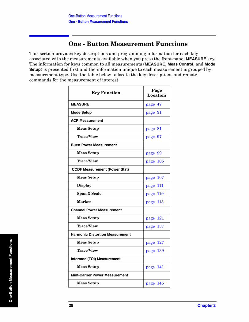
One-Button Measurement FunctionsOne - Button Measurement Functions
On
e-B
utt
on
Mea
sure
men
t F
un
ctio
ns
One - Button Measurement FunctionsThis section provides key descriptions and programming information for each key associated with the measurements available when you press the front-panel MEASURE key. The information for keys common to all measurements (MEASURE, Meas Control, and Mode Setup) is presented first and the information unique to each measurement is grouped by measurement type. Use the table below to locate the key descriptions and remote commands for the measurement of interest.
Key Function Page Location
MEASURE page 47
Mode Setup page 31
ACP Measurement
Meas Setup page 81
Trace/View page 97
Burst Power Measurement
Meas Setup page 99
Trace/View page 105
CCDF Measurement (Power Stat)
Meas Setup page 107
Display page 111
Span X Scale page 119
Marker page 113
Channel Power Measurement
Meas Setup page 121
Trace/View page 137
Harmonic Distortion Measurement
Meas Setup page 127
Trace/View page 139
Intermod (TOI) Measurement
Meas Setup page 141
Mult-Carrier Power Measurement
Meas Setup page 145
28 Chapter 2
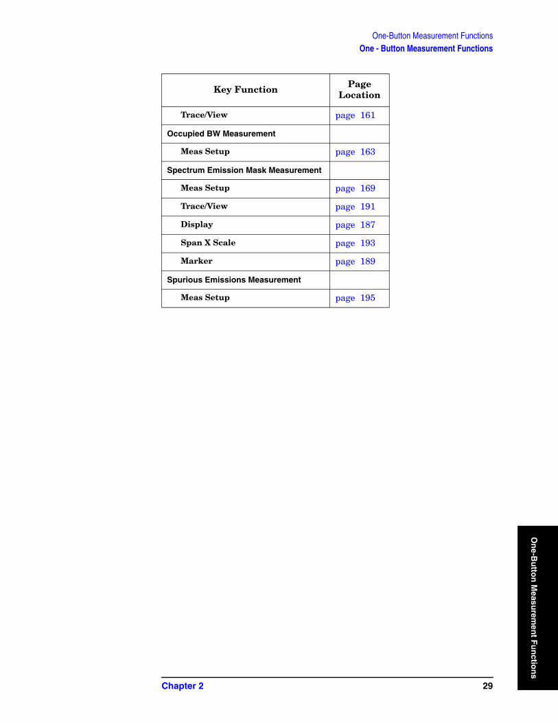
One-Button Measurement FunctionsOne - Button Measurement Functions
On
e-Bu
tton
Measu
remen
t Fu
nctio
Trace/View page 161
Occupied BW Measurement
Meas Setup page 163
Spectrum Emission Mask Measurement
Meas Setup page 169
Trace/View page 191
Display page 187
Span X Scale page 193
Marker page 189
Spurious Emissions Measurement
Meas Setup page 195
Key Function Page Location
Chapter 2 29
ns

One-Button Measurement FunctionsOne - Button Measurement Functions
On
e-B
utt
on
Mea
sure
men
t F
un
ctio
ns
30 Chapter 2
One-Button Measurement FunctionsMode Setup (Spectrum Analysis Mode)
On
e-Bu
tton
Measu
remen
t Fu
nctio
2.1 Mode Setup (Spectrum Analysis Mode) Enables you to change measurement settings common to all measurements in the MEASURE menu. In Spectrum Analysis mode, there are several built-in power measurements. Parameters that you set in the Mode Setup menu affect all of these measurements.
Key Path: Front-panel key
2.1.1 Radio Std
Accesses the available radio standards. Selecting a radio standard modifies spectrum analyzer settings for the measurements activated under the MEASURE menu.
Measurements that are not relevant to the selected radio standard are not available (grayed out) and they do not have instrument default settings associated with them. If Enable All Measurements is set to Yes when the Radio Std is pressed, only the standards that are relevant to the currently active measurement will be available. Unavailable standards are grayed out.
Key Path: Mode Setup
Factory Preset: None
History: Updated with PSA firmware revision A.06.00
Updated with PSA firmware revision A.04.00
Added with PSA firmware revision A.02.00
Modified with ESA firmware revision A.08.00
Added with ESA firmware revision A.07.00
Remote Command:
For PSA only: [:SENSe]:RADio:STANdard[:SELect] NONE|IS95a|JSTD|IS95C|GSM|W3GPP|C2000MC1|C2000DS|C2000MC3|NADC|PDC|BLUEtooth|TETRa|WL802DOT11A|WL802DOT11B|WL802DOT11G|WL802DOT11N|HIPERLAN2|DVBTDLN|DVBTGPN|DVBTIPN|FCC15|SDMBSE|UWBINDOOR|
For ESA only: [:SENSe]:RADio:STANdard[:SELect] NONE|IS95a|JSTD|IS95C|GSM|W3GPP|C2000MC1|C2000DS|C2000MC3|NADC|PDC|BLUEtooth|TETRa|WL802DOT11A|WL802DOT11B|WL802DOT11G|HIPERLAN2|DVBTLSNDVBTGPN|DVBTIPN|
[:SENSe]:RADio:STANdard[:SELect]?
Chapter 2 31
ns
One-Button Measurement FunctionsMode Setup (Spectrum Analysis Mode)
On
e-B
utt
on
Mea
sure
men
t F
un
ctio
ns
2.1.1.1 None
Selects no radio standard. If Radio Std, None is selected when a measurement is running, all measurement parameters are returned to their default values. Analyzer parameters outside the MEASURE or Meas Setup key menus are not affected.
Key Type: 1 of N menu
Key Path: Mode Setup, Radio Std
History: Modified with PSA firmware revision A.04.00
Added with PSA firmware revision A.02.00
Modified with ESA firmware revision A.08.00
Added with ESA firmware revision A.07.00
Remote Command:
Use[:SENSe]:RADio:STANdard[:SELect] See “Radio Std” on page 31.
Example: RAD:STAN NONE
2.1.1.2 IS-95A
Sets the specific parameters for the selected measurement (located under the “MEASURE (Spectrum Analysis Mode)” key description) appropriate for industry standard IS-95A. The Spectrum Emissions Mask, Harmonic Distortion, and Spurious Emissions measurements are not available when this radio standard is selected.
Key Type: 1 of N menu
Key Path: Mode Setup, Radio Std
History: Modified with PSA firmware revision A.04.00
Added with PSA firmware revision A.02.00
Modified with ESA firmware revision A.08.00
Added with ESA firmware revision A.07.00
Remote Command:
Use[:SENSe]:RADio:STANdard[:SELect] See “Radio Std” on page 31.
Example: RAD:STAN IS95
32 Chapter 2

One-Button Measurement FunctionsMode Setup (Spectrum Analysis Mode)
On
e-Bu
tton
Measu
remen
t Fu
nctio
2.1.1.3 J-STD-008
Sets the specific parameters for the selected measurement (located under the “MEASURE (Spectrum Analysis Mode)” key description) appropriate for industry standard J-STD-008. The Spectrum Emissions Mask, Harmonic Distortion, MCP, and Spurious Emissions measurements are not available when this radio standard is selected.
Key Type: 1 of N menu
Key Path: Mode Setup, Radio Std
History: Modified with PSA firmware revision A.04.00
Added with PSA firmware revision A.02.00
Modified with ESA firmware revision A.08.00
Added with ESA firmware revision A.07.00
Remote Command:
Use[:SENSe]:RADio:STANdard[:SELect] See “Radio Std” on page 31.
Example: RAD:STAN JSTD
2.1.1.4 IS-95C
Sets the specific parameters for the selected measurement (located under the “MEASURE (Spectrum Analysis Mode)” key description) appropriate for industry standard IS-95C. The IS-95C radio standard is only available when selecting the Channel Power, Occupied Bandwidth, Adjacent Channel Power, and CCDF one-button measurements.
Key Type: 1 of N menu
Key Path: Mode Setup, Radio Std
History: Modified with PSA firmware revision A.04.00
Added with PSA firmware revision A.02.00
Modified with ESA firmware revision A.10.00
Added with ESA firmware revision A.07.00
Remote Command:
Use[:SENSe]:RADio:STANdard[:SELect] See “Radio Std” on page 31.
Example: RAD:STAN IS95C
Chapter 2 33
ns
One-Button Measurement FunctionsMode Setup (Spectrum Analysis Mode)
On
e-B
utt
on
Mea
sure
men
t F
un
ctio
ns
2.1.1.5 GSM/EDGE
Sets the specific parameters for the selected measurement (located under the “MEASURE (Spectrum Analysis Mode)” key description) appropriate for industry standard GSM/EDGE. Power Stat CCDF and Burst Power are the only measurements available for this standard.
Key Type: 1 of N menu
Key Path: Mode Setup, Radio Std
History: Modified with PSA firmware revision A.04.00
Added with PSA firmware revision A.02.00
Modified with ESA firmware revision A.08.00
Added with ESA firmware revision A.07.00
Remote Command:
Use[:SENSe]:RADio:STANdard[:SELect] See “Radio Std” on page 31.
Example: RAD:STAN GSM
2.1.1.6 3GPP W-CDMA
Sets the specific parameters for the selected measurement (located under the “MEASURE (Spectrum Analysis Mode)” key description) appropriate for industry standard W-CDMA. All measurements except Harmonic Distortion and Spurious Emissions are available for this standard.
Key Type: 1 of N menu
Key Path: Mode Setup, Radio Std
History: Modified with PSA firmware revision A.04.00
Added with PSA firmware revision A.02.00
Modified with ESA firmware revision A.08.00
Added with ESA firmware revision A.07.00
Remote Command:
Use[:SENSe]:RADio:STANdard[:SELect] See “Radio Std” on page 31.
Example: RAD:STAN W3GPP
34 Chapter 2
One-Button Measurement FunctionsMode Setup (Spectrum Analysis Mode)
On
e-Bu
tton
Measu
remen
t Fu
nctio
2.1.1.7 cdma2000 MC-1X
Sets the specific parameters for the selected measurement (located under the “MEASURE (Spectrum Analysis Mode)” key description) appropriate for industry standard cdma2000-MC-1X. All measurements except Harmonic Distortion, Spurious Emissions, and Spectrum Emission Mask are available for this standard.
Key Type: 1 of N menu
Key Path: Mode Setup, Radio Std
History: Modified with PSA firmware revision A.04.00
Added with PSA firmware revision A.02.00
Modified with ESA firmware revision A.08.00
Added with ESA firmware revision A.07.00
Remote Command:
Use[:SENSe]:RADio:STANdard[:SELect] See “Radio Std” on page 31.
Example: RAD:STAN C2000MC1
2.1.1.8 cdma2000 MC-3X
Sets the specific parameters for the selected measurement (located under the “MEASURE (Spectrum Analysis Mode)” key description) appropriate for industry standard cdma2000:MC-3X. All measurements except Multi-Carrier Power, Harmonic Distortion, Spurious Emissions and Spectrum Emission Mask are available for this standard.
Key Type: 1 of N menu
Key Path: Mode Setup, Radio Std
History: Modified with PSA firmware revision A.04.00
Added with PSA firmware revision A.02.00
Modified with ESA firmware revision A.08.00
Added with ESA firmware revision A.07.00
Remote Command:
Use[:SENSe]:RADio:STANdard[:SELect] See “Radio Std” on page 31.
Example: RAD:STAN C2000MC3
Chapter 2 35
ns
One-Button Measurement FunctionsMode Setup (Spectrum Analysis Mode)
On
e-B
utt
on
Mea
sure
men
t F
un
ctio
ns
2.1.1.9 cdma2000 DS
Sets the specific parameters for the selected measurement (located under the “MEASURE (Spectrum Analysis Mode)” key description) appropriate for industry standard cdma2000:DS. All measurements except Multi-Carrier Power, Harmonic Distortion, Spurious Emissions and Spectrum Emission Mask are available for this standard.
Key Type: 1 of N menu
Key Path: Mode Setup, Radio Std
History: Modified with PSA firmware revision A.04.00
Added with PSA firmware revision A.02.00
Modified with ESA firmware revision A.08.00
Added with ESA firmware revision A.07.00
Remote Command:
Use[:SENSe]:RADio:STANdard[:SELect] See “Radio Std” on page 31.
Example: RAD:STAN C2000DS
2.1.1.10 NADC
Sets the specific parameters for the selected measurement (located under the “MEASURE (Spectrum Analysis Mode)” key description) appropriate for industry standard NADC. Channel Power and Intermod TOI measurements are not available when Device (MS) is selected. All other measurements are available when this radio standard is selected except: Spectrum Emissions Mask, Harmonic Distortion, Spurious Emissions, and Multi-Carrier Power.
Key Type: 1 of N menu
Key Path: Mode Setup, Radio Std
History: Modified with PSA firmware revision A.04.00
Added with PSA firmware revision A.02.00
Modified with ESA firmware revision A.08.00
Added with ESA firmware revision A.07.00
Remote Command:
Use[:SENSe]:RADio:STANdard[:SELect] See “Radio Std” on page 31.
Example: RAD:STAN NADC
36 Chapter 2
One-Button Measurement FunctionsMode Setup (Spectrum Analysis Mode)
On
e-Bu
tton
Measu
remen
t Fu
nctio
2.1.1.11 PDC
Sets the specific parameters for the selected measurement (located under the “MEASURE (Spectrum Analysis Mode)” key description) appropriate for industry standard PDC. The Burst Power measurement is not available when Device (BTS) is selected. The Channel Power and Intermod TOI measurements are not available when Device (MS) is selected. All other measurements except Multi-Carrier Power, Harmonic Distortion, Spurious Emissions and Spectrum Emission Mask measurements are available for this standard.
Key Type: 1 of N menu
Key Path: Mode Setup, Radio Std
History: Modified with PSA firmware revision A.04.00
Added with PSA firmware revision A.02.00
Modified with ESA firmware revision A.08.00
Added with ESA firmware revision A.07.00
Remote Command:
Use[:SENSe]:RADio:STANdard[:SELect] See “Radio Std” on page 31.
Example: RAD:STAN PDC
2.1.1.12 Bluetooth™
Sets the specific parameters for the selected measurement (located under the “MEASURE (Spectrum Analysis Mode)” key description) appropriate for industry standard Bluetooth™. Power Stat CCDF and Burst Power are the only measurements available for this standard.
Key Type: 1 of N menu
Key Path: Mode Setup, Radio Std
History: Modified with PSA firmware revision A.04.00
Added with PSA firmware revision A.02.00
Modified with ESA firmware revision A.08.00
Added with ESA firmware revision A.07.00
Remote Command:
Use[:SENSe]:RADio:STANdard[:SELect] See “Radio Std” on page 31.
Example: RAD:STAN BLUE
Chapter 2 37
ns

One-Button Measurement FunctionsMode Setup (Spectrum Analysis Mode)
On
e-B
utt
on
Mea
sure
men
t F
un
ctio
ns
2.1.1.13 TETRA
Sets the specific parameters for the selected measurement (located under the “MEASURE (Spectrum Analysis Mode)” key description) appropriate for industry standard TETRA. This standard is only available for the Channel Power and ACP measurements.
Key Type: 1 of N menu
Key Path: Mode Setup, Radio Std
History: Added with PSA firmware revision A.03.00
Added with ESA firmware revision A.09.00
Remote Command:
Use[:SENSe]:RADio:STANdard[:SELect] See “Radio Std” on page 31.
Example: RAD:STAN TETR
2.1.1.14 FCC Part 15 Subpart F (PSA Only)
Sets the specific parameters for the selected measurement (located under the “MEASURE (Spectrum Analysis Mode)” key description) appropriate for unlicensed devices. This standard is only available for the Spurious Emissions measurement.
Key Type: 1 of N menu
Key Path: Mode Setup, Radio Std
History: Added with PSA firmware revision A.06.00
Remote Command:
Use[:SENSe]:RADio:STANdard[:SELect] See “Radio Std” on page 31.
Example: RAD:STAN FCC15
2.1.1.15 WLAN
Accesses the WLAN radio standards key menu to enable you to select a WLAN standard. Selecting a radio standard modifies spectrum analyzer settings for the SEM measurement activated under the MEASURE menu.
2.1.1.15.1 802.11a
Sets the specific parameters for the selected measurement (located under the “MEASURE (Spectrum Analysis Mode)” key description) appropriate for industry standard 802.11a. This standard is only available for the Spectrum Emission Mask (SEM) measurement.
Key Type: 1 of N menu
Key Path: Mode Setup, Radio Std
38 Chapter 2
One-Button Measurement FunctionsMode Setup (Spectrum Analysis Mode)
On
e-Bu
tton
Measu
remen
t Fu
nctio
History: Added with PSA firmware revision A.08.00
Remote Command:
Use[:SENSe]:RADio:STANdard[:SELect] See “Radio Std” on page 31.
Example: RAD:STAN WL802DOT11A
2.1.1.15.2 802.11b
Sets the specific parameters for the selected measurement (located under the “MEASURE (Spectrum Analysis Mode)” key description) appropriate for industry standard 802.11b. This standard is only available for the Spectrum Emission Mask (SEM) measurement.
Key Type: 1 of N menu
Key Path: Mode Setup, Radio Std
History: Added with PSA firmware revision A.08.00
Remote Command:
Use[:SENSe]:RADio:STANdard[:SELect] See “Radio Std” on page 31.
Example: RAD:STAN WL802DOT11B
2.1.1.15.3 802.11g
Sets the specific parameters for the selected measurement (located under the “MEASURE (Spectrum Analysis Mode)” key description) appropriate for industry standard 802.11g. This standard is only available for the Spectrum Emission Mask (SEM) measurement.
Key Type: 1 of N menu
Key Path: Mode Setup, Radio Std
History: Added with PSA firmware revision A.08.00
Remote Command:
Use[:SENSe]:RADio:STANdard[:SELect] See “Radio Std” on page 31.
Example: RAD:STAN WL802DOT11G
2.1.1.15.4 802.11n
Sets the specific parameters for the selected measurement (located under the “MEASURE (Spectrum Analysis Mode)” key description) appropriate for industry standard 802.11n. This standard is only available for the Spectrum Emission Mask (SEM) measurement.
Key Type: 1 of N menu
Key Path: Mode Setup, Radio Std
History: Added with PSA firmware revision A.09.18
Chapter 2 39
ns
One-Button Measurement FunctionsMode Setup (Spectrum Analysis Mode)
On
e-B
utt
on
Mea
sure
men
t F
un
ctio
ns
Remote Command:
Use[:SENSe]:RADio:STANdard[:SELect] See “Radio Std” on page 31.
Example: RAD:STAN WL802DOT11N
2.1.1.15.5 Hiper LAN/2
Sets the specific parameters for the selected measurement (located under the “MEASURE (Spectrum Analysis Mode)” key description) appropriate for industry standard Hiper LAN2. This standard is only available for the Spectrum Emission Mask (SEM) measurement.
Key Type: 1 of N menu
Key Path: Mode Setup, Radio Std
History: Added with PSA firmware revision A.08.00
Remote Command:
Use[:SENSe]:RADio:STANdard[:SELect] See “Radio Std” on page 31.
Example: RAD:STAN HIPERLAN2
2.1.1.16 DVB-T
Accesses the DVB-T key menu to enable you to select a DVB-T mask filtering standard. Selecting a DVB-T filtering standard modifies spectrum analyzer settings for the CHP or CCDF measurement activated under the MEASURE menu.
2.1.1.16.1 L/SECAM/NICAM Pressing L/SECAM/NICAM selects the filtering masks for the L/SECAM/NICAM analog television system. This standard is only available for the channel power and CCDF measurements
Key Path: Mode Setup, DVB-T
History: Added with PSA firmware revision A.04.00
Added with ESA firmware revision A.10.00
Remote Command:
Use[:SENSe]:RADio:STANdard[:SELect] See “Radio Std” on page 31.
Example: RAD:STAN DVBTLSN
40 Chapter 2
One-Button Measurement FunctionsMode Setup (Spectrum Analysis Mode)
On
e-Bu
tton
Measu
remen
t Fu
nctio
2.1.1.16.2 G/PAL/NICAM
Pressing G/PAL/NICAM selects the filtering masks for the G/PAL/NICAM analog television system. This standard is only available for the channel power and CCDF measurements.
NOTE The ESA series analyzers require Fast ADC (Option AYX or B7D) to be installed for CCDF operation.
Key Path: Mode Setup, DVB-T
History: Added with PSA firmware revision A.04.00
Added with ESA firmware revision A.10.00
Remote Command:
Use[:SENSe]:RADio:STANdard[:SELect] See “Radio Std” on page 31.
Example: RAD:STAN DVBTGPN
2.1.1.16.3 I/PAL/NICAM
Pressing I/PAL/NICAM selects the filtering masks for the I/PAL/NICAM analog television system. This standard is only available for the channel power and CCDF measurements.
NOTE The ESA series analyzers require Fast ADC (Option AYX or B7D) to be installed for CCDF operation.
Key Path: Mode Setup, DVB-T
History: Added with PSA firmware revision A.04.00
Added with ESA firmware revision A.10.00
Remote Command:
Use[:SENSe]:RADio:STANdard[:SELect] See “Radio Std” on page 31.
Example: RAD:STAN DVBTIPN
2.1.1.17 S-DMB
Accesses the S-DMB radio standards key menu to enable you to select a S-DMB standard. Selecting a radio standard modifies spectrum analyzer settings for the Spurious Emissions measurement activated under the MEASURE menu. This standard is only available for the Channel Power, Occupied BW, and ACP measurements
Key Type: 1 of N menu
Key Path: Mode Setup, Radio Std
History: Added with PSA firmware revision A.06.00
Chapter 2 41
ns
One-Button Measurement FunctionsMode Setup (Spectrum Analysis Mode)
On
e-B
utt
on
Mea
sure
men
t F
un
ctio
ns
2.1.1.17.1 System E
(PSA Only):Sets the specific parameters for the selected measurement (located under the “MEASURE (Spectrum Analysis Mode)” key description) appropriate for industry standard System E. This standard is only available for the Channel Power, Occupied BW, or ACP measurements.
Key Type: 1 of N menu
Key Path: Mode Setup, Radio Std
History: Added with PSA firmware revision A.06.00
Remote Command:
Use[:SENSe]:RADio:STANdard[:SELect] See “Radio Std” on page 31.
Example: RAD:STAN DVBTGPN
2.1.1.18 UWB
Accesses the UWB radio standards key menu to enable you to select a UWB standard. Selecting a radio standard modifies spectrum analyzer settings for the Spurious Emissions measurement activated under the MEASURE menu.
Key Type: 1 of N menu
Key Path: Mode Setup, Radio Std
History: Added with PSA firmware revision A.06.00
2.1.1.18.1 UWB Indoor
Sets the specific parameters for the selected measurement (located under the “MEASURE (Spectrum Analysis Mode)” key description) appropriate for UWB Indoor standard. This standard is only available for the Spurious Emissions measurement.
Key Type: 1 of N menu
Key Path: Mode Setup, Radio Std
History: Added with PSA firmware revision A.06.00
Remote Command:
Use[:SENSe]:RADio:STANdard[:SELect] See “Radio Std” on page 31.
Example: RAD:STAN UWBINDOOR
42 Chapter 2

One-Button Measurement FunctionsMode Setup (Spectrum Analysis Mode)
On
e-Bu
tton
Measu
remen
t Fu
nctio
2.1.2 Radio Std Setup
Accesses the key menu for selecting the device, packet type, or signal bandwidth to be measured.
Key Path: Mode Setup
History: Modified with PSA firmware revision A.04.00
Added with PSA firmware revision A.02.00
Modified with ESA firmware revision A.08.00
Added with ESA firmware revision A.07.00
Remote Command:
There is no equivalent remote command.
2.1.2.1 Signal BW
Allows you to set the measurement bandwidth when Radio Std (None) is selected. This function is available only when you select None as the standard.
Key Path: Mode Setup, Radio Std Setup
Factory Preset: 3.0 MHz
Default Terminator: Hz
Range: The non-zero span range of the analyzer
History: Modified with PSA firmware revision A.04.00
Added with PSA firmware revision A.02.00
Modified with ESA firmware revision A.08.00
Added with ESA firmware revision A.07.00
Remote Command:
[:SENSe]:RADio:STANdard:SBWidth <freq>
[:SENSe]:RADio:STANdard:SBWidth?
Example: RAD:STAN:SBW 2MHZ
2.1.2.2 Device BTS/MS
This function is only available when you have selected the standard: IS-95, J-STD-008, cdma2000, W-CDMA, NADC, PDC, TETRA, or GSM. It enables you to select either the base transmitter station (BTS) setup defaults or the mobile station (MS) defaults for the standard that you have selected. This key is unavailable when you select Bluetooth™ or FCC Part 15.
Chapter 2 43
ns

One-Button Measurement FunctionsMode Setup (Spectrum Analysis Mode)
On
e-B
utt
on
Mea
sure
men
t F
un
ctio
ns
Key Path: Mode Setup, Radio Std Setup
Factory Preset: BTS
History: Modified with PSA firmware revision A.04.00
Added with PSA firmware revision A.02.00
Modified with ESA firmware revision A.08.00
Added with ESA firmware revision A.07.00
Remote Command:
[:SENSe]:RADio:STANdard:DEVice BTS|MS
[:SENSe]:RADio:STANdard:DEVice?
Example: RAD:STAN:DEV MS
2.1.2.3 Packet Type
This function is only available when the standard you have selected is Bluetooth™. It enables you to set the instrument settings for testing DH1, DH3, or DH5 packet type.
Key Path: Mode Setup, Radio Std Setup
Factory Preset: DH1
History: Modified with PSA firmware revision A.04.00
Added with PSA firmware revision A.02.00
Modified with ESA firmware revision A.08.00
Added with ESA firmware revision A.07.00
Remote Command:
[:SENSe]:RADio:STANdard:PACKet DH1|DH3|DH5
[:SENSe]:RADio:STANdard:PACKet?
Example: RAD:STAN:PACK DH1
2.1.2.4 Band Class
This function is only available when you have selected the standard: IS-95C. It enables you to select the band class.
Key Path: Mode Setup, Radio Std Setup
Factory Preset: US/K or Cell
History: Modified with PSA firmware revision A.04.00
Added with PSA firmware revision A.02.00
Modified with ESA firmware revision A.08.00
Added with ESA firmware revision A.07.00
44 Chapter 2
One-Button Measurement FunctionsMode Setup (Spectrum Analysis Mode)
On
e-Bu
tton
Measu
remen
t Fu
nctio
Remote Command:
[:SENSe]:RADio:STANdard:BAND:CLASs BC0|BC1
[:SENSe]:RADio:STANdard:BAND:CLASs?
Example: RAD:STAN:BAND:CLAS BC1
2.1.3 Retain Params
Enables you to retain the base-instrument parameter settings used by individual measurements that are typically lost when switching between measurements.
When Retain Params is set to Off, the values of the fully configurable parameters are not saved and recalled during a measurement change.
When Retain Params is set to On, the fully configurable parameters will be saved and recalled during a measurement change, along with Span, Ref Level, Single/Cont, Detector, Avg/VBW Type, Points, and if applicable, Spectrum/Bar/Combined and Graticule On/Off.
NOTE When Radio Std or Radio Std Setup is changed, Retain Params is set to Off. Once Retain Params has been set to Off, parameters will no longer be retained and any settings you may have entered will be lost.
Key Path: Mode Setup
Factory Preset: Off
History: Added with PSA firmware revision A.04.00
Added with ESA firmware revision A.10.00
Remote Command:
[:SENSe]:RADio:STANdard:RPARams[:STATe]ON|Off|1|0
[:SENSe]:RADio:STANdard:RPARams[:STATe]?
Example: RAD:STAN:RPAR Off
2.1.4 Enable All Measurements
Enable All Measurements allows you to access measurements that are disabled. Not all measurements are available for a particular radio standard. When you select a radio standard, the keys are grayed out for the measurements that are not available. These disabled measurements do not have default settings for the standard that you have selected. So you have to configure the settings yourself when you use them. See also the Retain Params key function.
Chapter 2 45
ns
One-Button Measurement FunctionsMode Setup (Spectrum Analysis Mode)
On
e-B
utt
on
Mea
sure
men
t F
un
ctio
ns
If you set Enable All Measurements to Yes and you enter one of the measurements that was disabled, then the Enable All Measurements function will not be available (grayed out). You cannot turn it off until you enter a measurement that is valid for your selected standard.
Key Path: Mode Setup
Factory Preset: No
History: Added with PSA firmware revision A.04.00
Added with ESA firmware revision A.10.00
Remote Command:
[:SENSe]:RADio:STANdard:EAMeas YES|NO
[:SENSe]:RADio:STANdard:EAMeas?
Example: RAD:STAN:EAM YES
2.1.5 Autorange of Power Setting (Remote command only)
This command is the remote version of the Optimize Ref Level key. If this function is applicable to the currently selected measurement, this command sets the reference level and attenuator to optimum values based on the signal present at the input. Channel Power, Occupied Bandwidth, ACP, Multi Carrier Power, CCDF, Harmonic Distortion, Burst Power, Intermod (TOI) and SEM measurements are the only supported measurements for the reference level optimization.
NOTE There is always a minimum of 5 dB for ESA or 6 dB for PSA of attenuation set to protect the analyzer input.
History: Modified with PSA firmware revision A.04.00
Added with PSA firmware revision A.02.00
Modified with ESA firmware revision A.08.00
Added with ESA firmware revision A.07.00
Remote Command:
[:SENSe]:POWer[:RF]:RANGe:AUTO ONCE
Example: POW:RANG:AUTO ONCE
46 Chapter 2
One-Button Measurement FunctionsMEASURE (Spectrum Analysis Mode)
On
e-Bu
tton
Measu
remen
t Fu
nctio
2.2 MEASURE (Spectrum Analysis Mode) In the Spectrum Analysis mode (see the MODE key), this key displays a menu that lets you make transmitter power measurements such as adjacent channel power, occupied bandwidth, and harmonic distortion measurements. If other modes are available and have been selected, the measurements for that particular mode will be displayed. Some common settings can be made for these measurements using the function under the Mode Setup key. For example, you may select one of several radio standards available by pressing Mode Setup, Radio Std.
Use Meas Control to pause and resume the currently selected measurement and to select between continuous or single measurements. For information about Meas Control, see Volume 1, Core Spectrum Analyzer Functions User’s and Programmer’s Reference.
NOTE The measurements described in this book are available in SA mode (see MODE key). Other measurements are available in other modes if an optional personality is installed, use the appropriate user’s guide for information about those modes.
Chapter 2 47
ns

One-Button Measurement FunctionsMEASURE (Spectrum Analysis Mode)
On
e-B
utt
on
Mea
sure
men
t F
un
ctio
ns
Command Interactions: MEASure, CONFigure, FETCh, INITiate and READ
Figure 1 Measurement Group of Commands
48 Chapter 2
One-Button Measurement FunctionsMEASURE (Spectrum Analysis Mode)
On
e-Bu
tton
Measu
remen
t Fu
nctio
ns
Measure Commands:
:MEASure:<measurement>[n]?
This is a fast single-command way to make a measurement using the factory default instrument settings. These are the settings and units that conform to the Mode Setup settings (for example,. radio standard) that you have currently selected.
• Stops the current measurement (if any) and sets up the instrument for the specified measurement using the factory defaults
• Initiates the data acquisition for the measurement
• Blocks other SCPI communication, waiting until the measurement is complete before returning results.
• If the function does averaging, it is turned on and the number of averages is set to 10.
• After the data is valid it returns the scalar results, or the trace data, for the specified measurement. The type of data returned may be defined by an [n] value that is sent with the command.
The scalar measurement results will be returned if the optional [n] value is not included, or is set to 1. If the [n] value is set to a value other than 1, the selected trace data results will be returned. See each command for details of what types of scalar results or trace data results are available.
ASCII is the default format for the data output. Older versions of Spectrum Analysis and Phase Noise mode measurements only use ASCII.) The binary data formats should be used for handling large blocks of data since they are smaller and faster than the ASCII format. Refer to the FORMat:DATA command for more information.
If you need to change some of the measurement parameters from the factory default settings you can set up the measurement with the CONFigure command. Use the commands in the SENSe:<measurement> and CALCulate:<measurement> subsystems to change the settings. Then you can use the READ? command to initiate the measurement and query the results. See Figure 1.
If you need to repeatedly make a given measurement with settings other than the factory defaults, you can use the commands in the SENSe:<measurement> and CALCulate:<measurement> subsystems to set up the measurement. Then use the READ? command to initiate the measurement and query results.
Measurement settings persist if you initiate a different measurement and then return to a previous one. Use READ:<measurement>? if you want to use those persistent settings. If you want to go back to the default settings, use MEASure:<measurement>?.
Chapter 2 49
One-Button Measurement FunctionsMEASURE (Spectrum Analysis Mode)
On
e-B
utt
on
Mea
sure
men
t F
un
ctio
ns
Configure Commands:
:CONFigure:<measurement>
This command stops the current measurement (if any) and sets up the instrument for the specified measurement using the factory default instrument settings. It sets the instrument to single measurement mode but should not initiate the taking of measurement data unless INIT:CONTinuous is ON. After you change any measurement settings, the READ command can be used to initiate a measurement without changing the settings back to their defaults. In Spectrum Analysis mode the CONFigure command also turns the averaging function on and sets the number of averages to 10 for all measurements.
The CONFigure? query returns the current measurement name.
Fetch Commands:
:FETCh:<measurement>[n]?
This command puts selected data from the most recent measurement into the output buffer. Use FETCh if you have already made a good measurement and you want to return several types of data (different [n] values, for example both scalars and trace data) from a single measurement. FETCh saves you the time of re-making the measurement. You can only FETCh results from the measurement that is currently active, it will not change to a different measurement.
If you need to get new measurement data, use the READ command, which is equivalent to an INITiate followed by a FETCh.
The scalar measurement results will be returned if the optional [n] value is not included, or is set to 1. If the [n] value is set to a value other than 1, the selected trace data results will be returned. See each command for details of what types of scalar results or trace data results are available. The binary data formats should be used for handling large blocks of data since they are smaller and transfer faster then the ASCII format. (FORMat:DATA)
FETCh may be used to return results other than those specified with the original READ or MEASure command that you sent.
INITiate Commands:
:INITiate:<measurement>
This command is not available for measurements in all the instrument modes:
• Initiates a trigger cycle for the specified measurement, but does not output any data. You must then use the FETCh<meas> command to return data. If a measurement other than the current one is specified, the instrument will switch to that measurement and then initiate it.
For example, suppose you have previously initiated the ACP measurement, but now you are running the channel power measurement. If you send INIT:ACP? it will change from channel power to ACP and will initiate an ACP measurement.
• Does not change any of the measurement settings. For example, if you have previously started the ACP measurement and you send INIT:ACP? it will initiate a new ACP measurement using the same instrument settings as the last time ACP was run.
• If your selected measurement is currently active (in the idle state) it triggers the measurement, assuming the trigger conditions are met. Then it completes one trigger cycle. Depending upon the measurement and the number of averages, there may be multiple data acquisitions, with multiple trigger events, for one full trigger cycle. It also holds off additional commands on GPIB until the acquisition is complete.
50 Chapter 2
One-Button Measurement FunctionsMEASURE (Spectrum Analysis Mode)
On
e-Bu
tton
Measu
remen
t Fu
nctio
2.2.1 Current Measurement Query (Remote Command Only)
This command returns the name of the measurement that is currently running.
Remote Command:
:CONFigure?
Example: CONF?
2.2.2 Test Current Results Against all Limits (Remote Command Only)
Allows you to check the status of the fail flag. This will return true (non-zero) if the flag is set to FAIL. A false (zero) is returned if the flag is set to TRUE. The fail flag is updated after every sweep.
This flag is only used by Channel Power (DVD-T radio standards only), Adjacent Channel Power, Multi-Carrier Power, Spurious Emissions, and SEM. For all other measurements, the fail flag will not be displayed and the SCPI command will return 0.
Remote Command:
:CALCulate:CLIMits:FAIL?
Example: CALC:CLIM:FAIL?
READ Commands:
:READ:<measurement>[n]?
• Does not preset the measurement to the factory default settings. For example, if you have previously initiated the ACP measurement and you send READ:ACP? it will initiate a new measurement using the same instrument settings.
• Initiates the measurement and puts valid data into the output buffer. If a measurement other than the current one is specified, the instrument will switch to that measurement before it initiates the measurement and returns results.
For example, suppose you have previously initiated the ACP measurement, but now you are running the channel power measurement. Then you send READ:ACP? It will change from channel power back to ACP and, using the previous ACP settings, will initiate the measurement and return results.
• Blocks other SCPI communication, waiting until the measurement is complete before returning the results
If the optional [n] value is not included, or is set to 1, the scalar measurement results will be returned. If the [n] value is set to a value other than 1, the selected trace data results will be returned. See each command for details of what types of scalar results or trace data results are available. The binary data formats should be used when handling large blocks of data since they are smaller and faster then the ASCII format. (FORMat:DATA)
Chapter 2 51
ns
One-Button Measurement FunctionsMEASURE (Spectrum Analysis Mode)
On
e-B
utt
on
Mea
sure
men
t F
un
ctio
ns
2.2.3 Meas Off
This key accesses the core spectrum analysis measurement functionality. It turns off the current one-button measurement so there are no keys available in the Meas Setup menu. See the spectrum analysis measurement features described in Volume 1 “Core Spectrum Analyzer Functions”.
Key Path: MEASURE
Saved State: Saved in state
Factory Preset: Meas Off is selected.
Remote Command:
:CONFigure:SANalyzer
Example: CONF:SAN
2.2.4 Channel Power
Channel Power measures the power and power spectral density in the channel bandwidth that you specify. One marker pair on the display indicates the edges of the channel bandwidth. The center frequency, reference level, and channel bandwidth must be set by the user. For more information see “Meas Setup (Channel Power—CHP)” on page 121.
You can configure measurement settings by pressing Meas Setup after selecting Channel Power. You can make a measurement in single or continuous sweep mode. Pressing Meas Control enables you to pause or restart a measurement, or toggle between continuous and single measurement. To set Ref Level automatically, use Optimize Ref Level.
The power calculation method used to determine the channel power is a traditional method known as the integration bandwidth (IBW) method. A swept spectrum is used as the basis for this calculation. Therefore, it is important to set the resolution bandwidth correctly before making this measurement using the following formula:
Where k is a value between 1.2 and 4.0 and n is the number of trace points.
NOTE Because of the noise-like nature of the signals being measured, the video bandwidth should be ≥ 10 times the resolution bandwidth.
RBW k span( ) n⁄=
52 Chapter 2
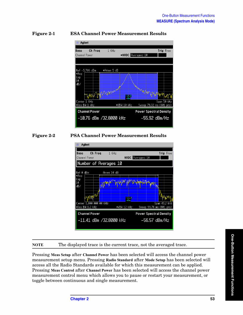
One-Button Measurement FunctionsMEASURE (Spectrum Analysis Mode)
On
e-Bu
tton
Measu
remen
t Fu
nctio
Figure 2-1 ESA Channel Power Measurement Results
Figure 2-2 PSA Channel Power Measurement Results
NOTE The displayed trace is the current trace, not the averaged trace.
Pressing Meas Setup after Channel Power has been selected will access the channel power measurement setup menu. Pressing Radio Standard after Mode Setup has been selected will access all the Radio Standards available for which this measurement can be applied. Pressing Meas Control after Channel Power has been selected will access the channel power measurement control menu which allows you to pause or restart your measurement, or toggle between continuous and single measurement.
Chapter 2 53
ns
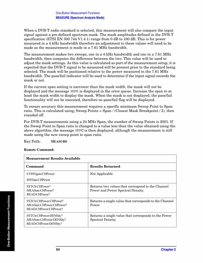
One-Button Measurement FunctionsMEASURE (Spectrum Analysis Mode)
On
e-B
utt
on
Mea
sure
men
t F
un
ctio
ns
When a DVB-T radio standard is selected, this measurement will also compare the input signal against a pre-defined spectrum mask. The mask amplitudes defined in the DVB-T specification (ETSI EN 300 744 V1.4.1) range from 0 dB to 100 dB. This is for power measured in a 4 kHz bandwidth therefore an adjustment to these values will need to be made as the measurement is made in a 7.61 MHz bandwidth.
The measurement makes two sweeps, one in a 4 kHz bandwidth and one in a 7.61 MHz bandwidth, then computes the difference between the two. This value will be used to adjust the mask settings. As this value is calculated as part of the measurement setup, it is expected that the DVB-T signal to be measured will be present prior to the standard being selected. The mask will be positioned relative to the power measured in the 7.61 MHz bandwidth. The pass/fail indicator will be used to determine if the input signal exceeds the mask or not.
If the current span setting is narrower than the mask width, the mask will not be displayed and the message 10191 is displayed in the error queue. Increase the span to at least the mask width to display the mask. When the mask is not displayed, the pass/fail functionality will not be executed, therefore no pass/fail flag will be displayed.
To ensure accuracy this measurement requires a specific minimum Sweep Point to Span ratio. This is calculated using; Sweep Points = Span / (Closest Mask Breakpoint / 2), then rounded off.
For DVB-T measurements using a 24 MHz Span, the number of Sweep Points is 2001. If the Sweep Point to Span ratio is changed to a value less than the value obtained using the above algorithm, the message 10192 is then displayed, although the measurement is still made using the new sweep point to span ratio.
Key Path: MEASURE
Remote Command:
Measurement Results Available
Command Results Returned
:CONFigure:CHPower
:INITiate:CHPower
Not Applicable
:FETCh:CHPower?:MEASure:CHPower?:READ:CHPower?
Returns two values that correspond to the Channel Power and Power Spectral Density.
:FETCh:CHPower:CHPower?:MEASure:CHPower:CHPower?:READ:CHPower:CHPower?
Returns a single value that corresponds to the Channel Power.
:FETCh:CHPower:DENSity?:MEASure:CHPower:DENSity?:READ:CHPower:DENSity?
Returns a single value that corresponds to the Power Spectral Density.
54 Chapter 2
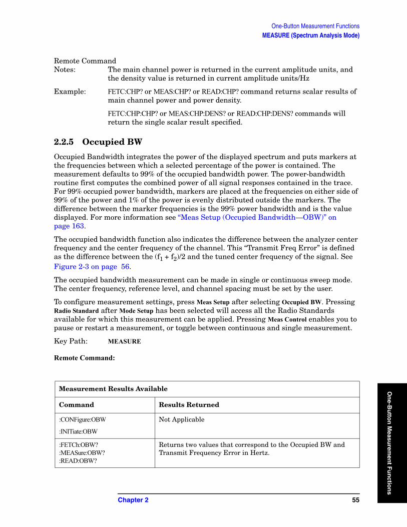
One-Button Measurement FunctionsMEASURE (Spectrum Analysis Mode)
On
e-Bu
tton
Measu
remen
t Fu
nctio
Remote CommandNotes: The main channel power is returned in the current amplitude units, and
the density value is returned in current amplitude units/Hz
Example: FETC:CHP? or MEAS:CHP? or READ:CHP? command returns scalar results of main channel power and power density.
FETC:CHP:CHP? or MEAS:CHP:DENS? or READ:CHP:DENS? commands will return the single scalar result specified.
2.2.5 Occupied BW
Occupied Bandwidth integrates the power of the displayed spectrum and puts markers at the frequencies between which a selected percentage of the power is contained. The measurement defaults to 99% of the occupied bandwidth power. The power-bandwidth routine first computes the combined power of all signal responses contained in the trace. For 99% occupied power bandwidth, markers are placed at the frequencies on either side of 99% of the power and 1% of the power is evenly distributed outside the markers. The difference between the marker frequencies is the 99% power bandwidth and is the value displayed. For more information see “Meas Setup (Occupied Bandwidth—OBW)” on page 163.
The occupied bandwidth function also indicates the difference between the analyzer center frequency and the center frequency of the channel. This “Transmit Freq Error” is defined as the difference between the (f1 + f2)/2 and the tuned center frequency of the signal. See Figure 2-3 on page 56.
The occupied bandwidth measurement can be made in single or continuous sweep mode. The center frequency, reference level, and channel spacing must be set by the user.
To configure measurement settings, press Meas Setup after selecting Occupied BW. Pressing Radio Standard after Mode Setup has been selected will access all the Radio Standards available for which this measurement can be applied. Pressing Meas Control enables you to pause or restart a measurement, or toggle between continuous and single measurement.
Key Path: MEASURE
Remote Command:
Measurement Results Available
Command Results Returned
:CONFigure:OBW
:INITiate:OBW
Not Applicable
:FETCh:OBW?:MEASure:OBW?:READ:OBW?
Returns two values that correspond to the Occupied BW and Transmit Frequency Error in Hertz.
Chapter 2 55
ns
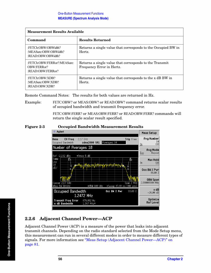
One-Button Measurement FunctionsMEASURE (Spectrum Analysis Mode)
On
e-B
utt
on
Mea
sure
men
t F
un
ctio
ns
Remote Command Notes: The results for both values are returned in Hz.
Example: FETC:OBW? or MEAS:OBW? or READ:OBW? command returns scalar results of occupied bandwidth and transmit frequency error.
FETC:OBW:FERR? or MEAS:OBW:FERR? or READ:OBW:FERR? commands will return the single scalar result specified.
Figure 2-3 Occupied Bandwidth Measurement Results
2.2.6 Adjacent Channel Power—ACP
Adjacent Channel Power (ACP) is a measure of the power that leaks into adjacent transmit channels. Depending on the radio standard selected from the Mode Setup menu, this measurement can run in several different modes in order to measure different types of signals. For more information see “Meas Setup (Adjacent Channel Power—ACP)” on page 81.
:FETCh:OBW:OBWidth?:MEASure:OBW:OBWidth?:READ:OBW:OBWidth?
Returns a single value that corresponds to the Occupied BW in Hertz.
:FETCh:OBW:FERRor?:MEASure:OBW:FERRor?:READ:OBW:FERRor?
Returns a single value that corresponds to the Transmit Frequency Error in Hertz.
:FETCh:OBW:XDB?:MEASure:OBW:XDB?:READ:OBW:XDB?
Returns a single value that corresponds to the x dB BW in Hertz.
Measurement Results Available
Command Results Returned
f2f1
56 Chapter 2
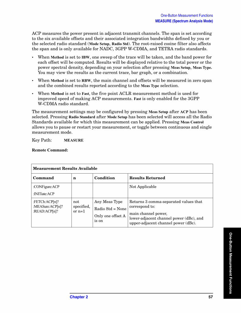
One-Button Measurement FunctionsMEASURE (Spectrum Analysis Mode)
On
e-Bu
tton
Measu
remen
t Fu
nctio
ACP measures the power present in adjacent transmit channels. The span is set according to the six available offsets and their associated integration bandwidths defined by you or the selected radio standard (Mode Setup, Radio Std). The root-raised cosine filter also affects the span and is only available for NADC, 3GPP W-CDMA, and TETRA radio standards.
• When Method is set to IBW, one sweep of the trace will be taken, and the band power for each offset will be computed. Results will be displayed relative to the total power or the power spectral density, depending on your selection after pressing Meas Setup, Meas Type. You may view the results as the current trace, bar graph, or a combination.
• When Method is set to RBW, the main channel and offsets will be measured in zero span and the combined results reported according to the Meas Type selection.
• When Method is set to Fast, the five point ACLR measurement method is used for improved speed of making ACP measurements. Fast is only enabled for the 3GPP W-CDMA radio standard.
The measurement settings may be configured by pressing Meas Setup after ACP has been selected. Pressing Radio Standard after Mode Setup has been selected will access all the Radio Standards available for which this measurement can be applied. Pressing Meas Control allows you to pause or restart your measurement, or toggle between continuous and single measurement mode.
Key Path: MEASURE
Remote Command:
Measurement Results Available
Command n Condition Results Returned
:CONFigure:ACP
:INITiate:ACP
Not Applicable
:FETCh:ACP[n]?:MEASure:ACP[n]?:READ:ACP[n]?
not specified, or n=1
Any Meas Type
Radio Std = None
Only one offset A is on
Returns 3 comma-separated values that correspond to:
main channel power, lower-adjacent channel power (dBc), andupper-adjacent channel power (dBc).
Chapter 2 57
ns

One-Button Measurement FunctionsMEASURE (Spectrum Analysis Mode)
On
e-B
utt
on
Mea
sure
men
t F
un
ctio
ns
not specified, or n=1
Meas Type = Total Power Reference
Method = IBW or RBW
Returns 28 comma-separated values, in the following order:
1. Center Frequency - relative power (dB)2. Center Frequency - absolute power (dBm)3. Center Frequency - relative power (dB)4. Center Frequency - absolute power (dBm)5. Negative Offset Frequency (1)
- relative power (dB)6. Negative Offset Frequency (1)
- absolute power (dBm)7. Positive Offset Frequency (1)
- relative power (dB)8. Positive Offset Frequency (1)
- absolute power (dBm)
...
25. Negative Offset Frequency (6) - relative power (dB)
26. Negative Offset Frequency (6)- absolute power (dBm)
27. Positive Offset Frequency (6)- relative power (dB)
28. Positive Offset Frequency (6)- absolute power (dBm)
The center frequency relative power is relative to the center frequency absolute power, and therefore is always equal to 0.00 dB.
not specified, or n=1
Meas Type = Total Power Reference
Method = Fast
Returns 5 comma-separated values, in the following order:
1. Main Carrier- absolute power (dBm)2. Negative Offset Frequency (1)
- absolute power (dBm)3. Positive Offset Frequency (1)
- absolute power (dBm)4. Negative Offset Frequency (2)
- absolute power (dBm)5. Positive Offset Frequency (2)
- absolute power (dBm)
Measurement Results Available (Continued)
Command n Condition Results Returned
58 Chapter 2
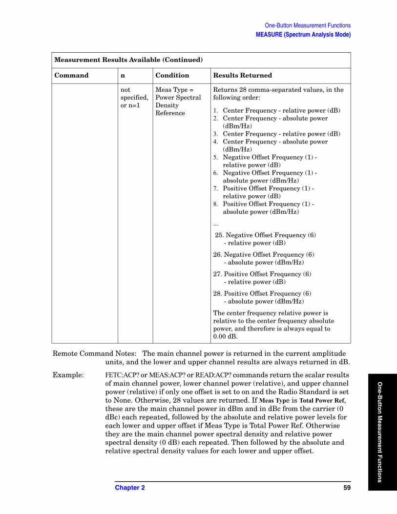
One-Button Measurement FunctionsMEASURE (Spectrum Analysis Mode)
On
e-Bu
tton
Measu
remen
t Fu
nctio
Remote Command Notes: The main channel power is returned in the current amplitude units, and the lower and upper channel results are always returned in dB.
Example: FETC:ACP? or MEAS:ACP? or READ:ACP? commands return the scalar results of main channel power, lower channel power (relative), and upper channel power (relative) if only one offset is set to on and the Radio Standard is set to None. Otherwise, 28 values are returned. If Meas Type is Total Power Ref, these are the main channel power in dBm and in dBc from the carrier (0 dBc) each repeated, followed by the absolute and relative power levels for each lower and upper offset if Meas Type is Total Power Ref. Otherwise they are the main channel power spectral density and relative power spectral density (0 dB) each repeated. Then followed by the absolute and relative spectral density values for each lower and upper offset.
not specified, or n=1
Meas Type = Power Spectral Density Reference
Returns 28 comma-separated values, in the following order:
1. Center Frequency - relative power (dB)2. Center Frequency - absolute power
(dBm/Hz)3. Center Frequency - relative power (dB)4. Center Frequency - absolute power
(dBm/Hz)5. Negative Offset Frequency (1) -
relative power (dB)6. Negative Offset Frequency (1) -
absolute power (dBm/Hz)7. Positive Offset Frequency (1) -
relative power (dB)8. Positive Offset Frequency (1) -
absolute power (dBm/Hz)
...
25. Negative Offset Frequency (6) - relative power (dB)
26. Negative Offset Frequency (6)- absolute power (dBm/Hz)
27. Positive Offset Frequency (6)- relative power (dB)
28. Positive Offset Frequency (6)- absolute power (dBm/Hz)
The center frequency relative power is relative to the center frequency absolute power, and therefore is always equal to 0.00 dB.
Measurement Results Available (Continued)
Command n Condition Results Returned
Chapter 2 59
ns
One-Button Measurement FunctionsMEASURE (Spectrum Analysis Mode)
On
e-B
utt
on
Mea
sure
men
t F
un
ctio
ns
2.2.7 Multi-Carrier Power
Multi-Carrier Power is the measure of the power that leaks into adjacent transmit channels when two or more carriers are present. The results reported are identical to the adjacent power measurement, but the setup is different to allow for two or more carriers. For more information see “Meas Setup (Multi-Carrier Power—MCP)” on page 145.
The measurement settings may be configured by pressing Meas Setup after Multi-Carrier Power has been selected. Pressing Meas Control allows you to pause or restart your measurement, or toggle between continuous and single measurement mode.
Key Path: MEASURE
Remote Command:
Measurement Results Available
Command n Results Returned
:CONFigure:MCPower N/A Not Applicable
60 Chapter 2

One-Button Measurement FunctionsMEASURE (Spectrum Analysis Mode)
On
e-Bu
tton
Measu
remen
t Fu
nctio
:FETCh:MCPower[n]?:MEASure:MCPower[n]?:READ:MCPower[n]?
n=1 (or not specified)
Returns 20 comma-separated scalar results, in the following order.
1. 0.0
2. Total carrier power (dBm)
3. 0.0
4. Reference carrier power (dBm)
5. lower 5 MHz offset - relative power (dBc)
6. lower 5 MHz offset - absolute power (dBm)
7. upper 5 MHz offset - relative power (dBc)
8. upper 5 MHz offset - absolute power (dBm)
9. lower 10 MHz offset - relative power (dBc)
10. lower 10 MHz offset - absolute power (dBm)
11. upper 10 MHz offset - relative power (dBc)
12. upper 10 MHz offset - absolute power (dBm)
13. lower 15 MHz offset - relative power (dBc)
14. lower 15 MHz offset - absolute power (dBm)
15. upper 15 MHz offset - relative power (dBc)
16. upper 15 MHz offset - absolute power (dBm)
17. NaN returned
18. NaN returned
19. NaN returned
20. NaN returned
If the results are not available, −999.0 is returned.
n=2...13 Returns absolute and relative values for carrier n-1. If results are not available −999.0 is returned
Measurement Results Available (Continued)
Command n Results Returned
Chapter 2 61
ns
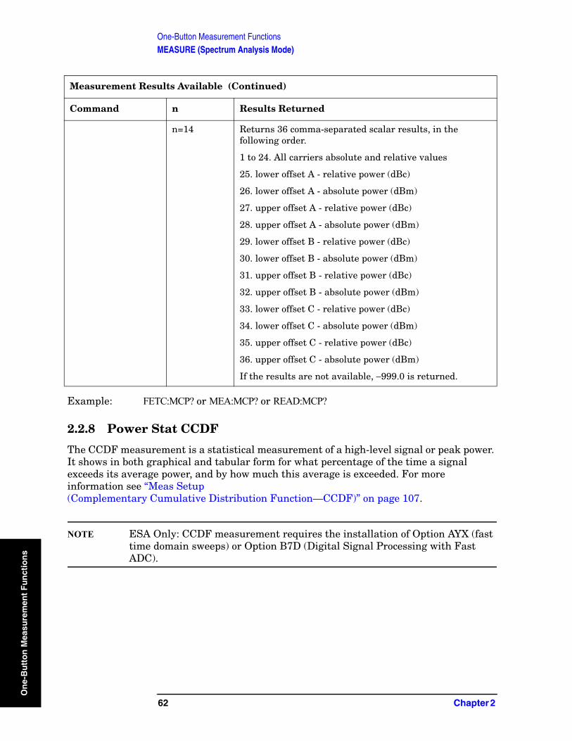
One-Button Measurement FunctionsMEASURE (Spectrum Analysis Mode)
On
e-B
utt
on
Mea
sure
men
t F
un
ctio
ns
Example: FETC:MCP? or MEA:MCP? or READ:MCP?
2.2.8 Power Stat CCDF
The CCDF measurement is a statistical measurement of a high-level signal or peak power. It shows in both graphical and tabular form for what percentage of the time a signal exceeds its average power, and by how much this average is exceeded. For more information see “Meas Setup (Complementary Cumulative Distribution Function—CCDF)” on page 107.
NOTE ESA Only: CCDF measurement requires the installation of Option AYX (fast time domain sweeps) or Option B7D (Digital Signal Processing with Fast ADC).
n=14 Returns 36 comma-separated scalar results, in the following order.
1 to 24. All carriers absolute and relative values
25. lower offset A - relative power (dBc)
26. lower offset A - absolute power (dBm)
27. upper offset A - relative power (dBc)
28. upper offset A - absolute power (dBm)
29. lower offset B - relative power (dBc)
30. lower offset B - absolute power (dBm)
31. upper offset B - relative power (dBc)
32. upper offset B - absolute power (dBm)
33. lower offset C - relative power (dBc)
34. lower offset C - absolute power (dBm)
35. upper offset C - relative power (dBc)
36. upper offset C - absolute power (dBm)
If the results are not available, −999.0 is returned.
Measurement Results Available (Continued)
Command n Results Returned
62 Chapter 2
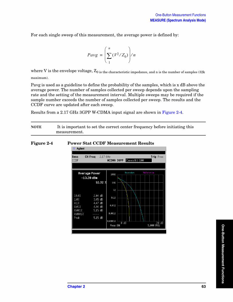
One-Button Measurement FunctionsMEASURE (Spectrum Analysis Mode)
On
e-Bu
tton
Measu
remen
t Fu
nctio
For each single sweep of this measurement, the average power is defined by:
where V is the envelope voltage, Z0 is the characteristic impedance, and n is the number of samples (32k
maximum).
Pavg is used as a guideline to define the probability of the samples, which is x dB above the average power. The number of samples collected per sweep depends upon the sampling rate and the setting of the measurement interval. Multiple sweeps may be required if the sample number exceeds the number of samples collected per sweep. The results and the CCDF curve are updated after each sweep.
Results from a 2.17 GHz 3GPP W-CDMA input signal are shown in Figure 2-4.
NOTE It is important to set the correct center frequency before initiating this measurement.
Figure 2-4 Power Stat CCDF Measurement Results
Pavg V2 Z0⁄( )1
n
∑⎝ ⎠⎜ ⎟⎜ ⎟⎛ ⎞
n⁄=
Chapter 2 63
ns
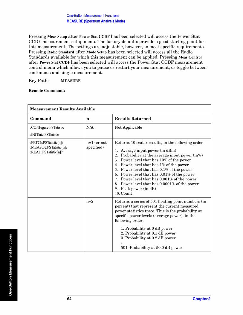
One-Button Measurement FunctionsMEASURE (Spectrum Analysis Mode)
On
e-B
utt
on
Mea
sure
men
t F
un
ctio
ns
Pressing Meas Setup after Power Stat CCDF has been selected will access the Power Stat CCDF measurement setup menu. The factory defaults provide a good starting point for this measurement. The settings are adjustable, however, to meet specific requirements. Pressing Radio Standard after Mode Setup has been selected will access all the Radio Standards available for which this measurement can be applied. Pressing Meas Control after Power Stat CCDF has been selected will access the Power Stat CCDF measurement control menu which allows you to pause or restart your measurement, or toggle between continuous and single measurement.
Key Path: MEASURE
Remote Command:
Measurement Results Available
Command n Results Returned
:CONFigure:PSTatistic
:INITiate:PSTatistic
N/A Not Applicable
:FETCh:PSTatistic[n]?:MEASure:PSTatistic[n]?:READ:PSTatistic[n]?
n=1 (or not specified)
Returns 10 scalar results, in the following order.
1. Average input power (in dBm) 2. Probability at the average input power (in%)3. Power level that has 10% of the power4. Power level that has 1% of the power5. Power level that has 0.1% of the power6. Power level that has 0.01% of the power7. Power level that has 0.001% of the power8. Power level that has 0.0001% of the power9. Peak power (in dB)10. Count
n=2 Returns a series of 501 floating point numbers (in percent) that represent the current measured power statistics trace. This is the probability at specific power levels (average power), in the following order:
1. Probability at 0 dB power2. Probability at 0.1 dB power3. Probability at 0.2 dB power…501. Probability at 50.0 dB power
64 Chapter 2
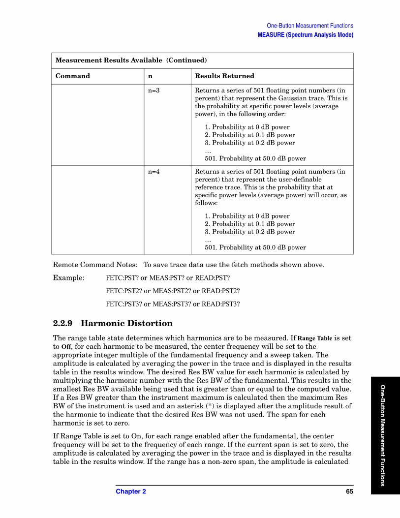
One-Button Measurement FunctionsMEASURE (Spectrum Analysis Mode)
On
e-Bu
tton
Measu
remen
t Fu
nctio
Remote Command Notes: To save trace data use the fetch methods shown above.
Example: FETC:PST? or MEAS:PST? or READ:PST?
FETC:PST2? or MEAS:PST2? or READ:PST2?
FETC:PST3? or MEAS:PST3? or READ:PST3?
2.2.9 Harmonic Distortion
The range table state determines which harmonics are to be measured. If Range Table is set to Off, for each harmonic to be measured, the center frequency will be set to the appropriate integer multiple of the fundamental frequency and a sweep taken. The amplitude is calculated by averaging the power in the trace and is displayed in the results table in the results window. The desired Res BW value for each harmonic is calculated by multiplying the harmonic number with the Res BW of the fundamental. This results in the smallest Res BW available being used that is greater than or equal to the computed value. If a Res BW greater than the instrument maximum is calculated then the maximum Res BW of the instrument is used and an asterisk (*) is displayed after the amplitude result of the harmonic to indicate that the desired Res BW was not used. The span for each harmonic is set to zero.
If Range Table is set to On, for each range enabled after the fundamental, the center frequency will be set to the frequency of each range. If the current span is set to zero, the amplitude is calculated by averaging the power in the trace and is displayed in the results table in the results window. If the range has a non-zero span, the amplitude is calculated
n=3 Returns a series of 501 floating point numbers (in percent) that represent the Gaussian trace. This is the probability at specific power levels (average power), in the following order:
1. Probability at 0 dB power2. Probability at 0.1 dB power3. Probability at 0.2 dB power…501. Probability at 50.0 dB power
n=4 Returns a series of 501 floating point numbers (in percent) that represent the user-definable reference trace. This is the probability that at specific power levels (average power) will occur, as follows:
1. Probability at 0 dB power2. Probability at 0.1 dB power3. Probability at 0.2 dB power…501. Probability at 50.0 dB power
Measurement Results Available (Continued)
Command n Results Returned
Chapter 2 65
ns

One-Button Measurement FunctionsMEASURE (Spectrum Analysis Mode)
On
e-B
utt
on
Mea
sure
men
t F
un
ctio
ns
by making a band-power measurement over the span and is displayed in the results table in the results window.
After the specified number of harmonics have been measured and their amplitudes displayed, the total harmonic distortion is computed and displayed in the left-hand portion of the window (view is set to Harmonics & THD). If the measurement is in single mode, the display will remain at the last harmonic setting and the analyzer sweep will be stopped. If the measurement is in continuous mode, the measurement will continually measure the amplitude of the fundamental and harmonics.
For averaged measurements, you may specify the number of sweeps over which the amplitude of each harmonic is measured. This means that if the Avg Number is set to 10, ten sweeps will be taken and averaged for each harmonic to be measured. The total harmonic distortion would then be calculated from these averaged amplitude readings. Averaging applies only to the amplitude of the harmonic, and does not affect the frequency at which the amplitude is measured.
Refer to your measurement guide for examples of this measurement and the calculation of Total Harmonic Distortion.
Key Path: MEASURE
Dependencies/Couplings: This measurement is not available when using external mixing.
Remote Command:
Measurement Results Available
Command n Results Returned
:CONFigure:HARMonics
:INITiate:HARMonics
N/A Not Applicable
:FETCh:HARMonics:AMPLitude:ALL?
:MEASure:HARMonics:AMPLitude:ALL?
:READ:HARMonics:AMPLitude:ALL?
N/A Returns the amplitude values of the first ten harmonics. The first value (for the fundamental) is measured in dBm. The remaining harmonics are measured in dBm from the fundamental. If fewer than ten harmonics are measured, zero is returned for any harmonic not measured.
:FETCh:HARMonics:AMPLitude[n]?
:MEASure:HARMonics:AMPLitude[n]?
:READ:HARMonics:AMPLitude[n]?
n=1 to 10 (n=1 for n not specified)
Returns the amplitude of the specified harmonic number n, where n=1 returns the amplitude of the fundamental in units of dBm.
For example, n = 9 returns the amplitude of the ninth harmonic measured in dBm from the fundamental.
66 Chapter 2
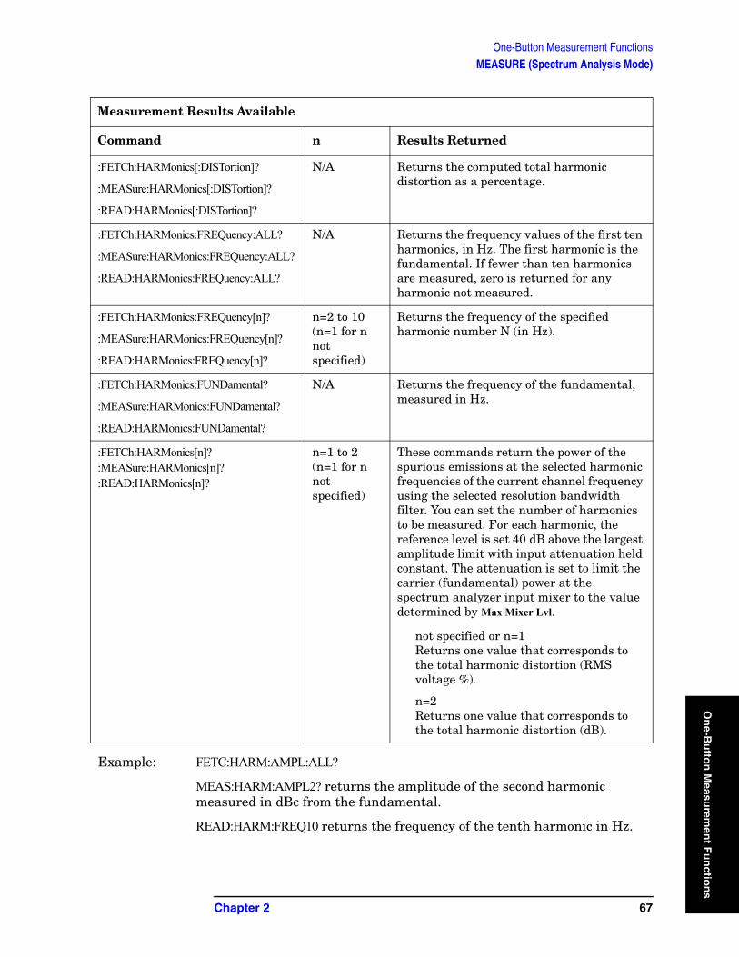
One-Button Measurement FunctionsMEASURE (Spectrum Analysis Mode)
On
e-Bu
tton
Measu
remen
t Fu
nctio
Example: FETC:HARM:AMPL:ALL?
MEAS:HARM:AMPL2? returns the amplitude of the second harmonic measured in dBc from the fundamental.
READ:HARM:FREQ10 returns the frequency of the tenth harmonic in Hz.
:FETCh:HARMonics[:DISTortion]?
:MEASure:HARMonics[:DISTortion]?
:READ:HARMonics[:DISTortion]?
N/A Returns the computed total harmonic distortion as a percentage.
:FETCh:HARMonics:FREQuency:ALL?
:MEASure:HARMonics:FREQuency:ALL?
:READ:HARMonics:FREQuency:ALL?
N/A Returns the frequency values of the first ten harmonics, in Hz. The first harmonic is the fundamental. If fewer than ten harmonics are measured, zero is returned for any harmonic not measured.
:FETCh:HARMonics:FREQuency[n]?
:MEASure:HARMonics:FREQuency[n]?
:READ:HARMonics:FREQuency[n]?
n=2 to 10 (n=1 for n not specified)
Returns the frequency of the specified harmonic number N (in Hz).
:FETCh:HARMonics:FUNDamental?
:MEASure:HARMonics:FUNDamental?
:READ:HARMonics:FUNDamental?
N/A Returns the frequency of the fundamental, measured in Hz.
:FETCh:HARMonics[n]?:MEASure:HARMonics[n]? :READ:HARMonics[n]?
n=1 to 2(n=1 for n not specified)
These commands return the power of the spurious emissions at the selected harmonic frequencies of the current channel frequency using the selected resolution bandwidth filter. You can set the number of harmonics to be measured. For each harmonic, the reference level is set 40 dB above the largest amplitude limit with input attenuation held constant. The attenuation is set to limit the carrier (fundamental) power at the spectrum analyzer input mixer to the value determined by Max Mixer Lvl.
not specified or n=1Returns one value that corresponds to the total harmonic distortion (RMS voltage %).
n=2Returns one value that corresponds to the total harmonic distortion (dB).
Measurement Results Available
Command n Results Returned
Chapter 2 67
ns
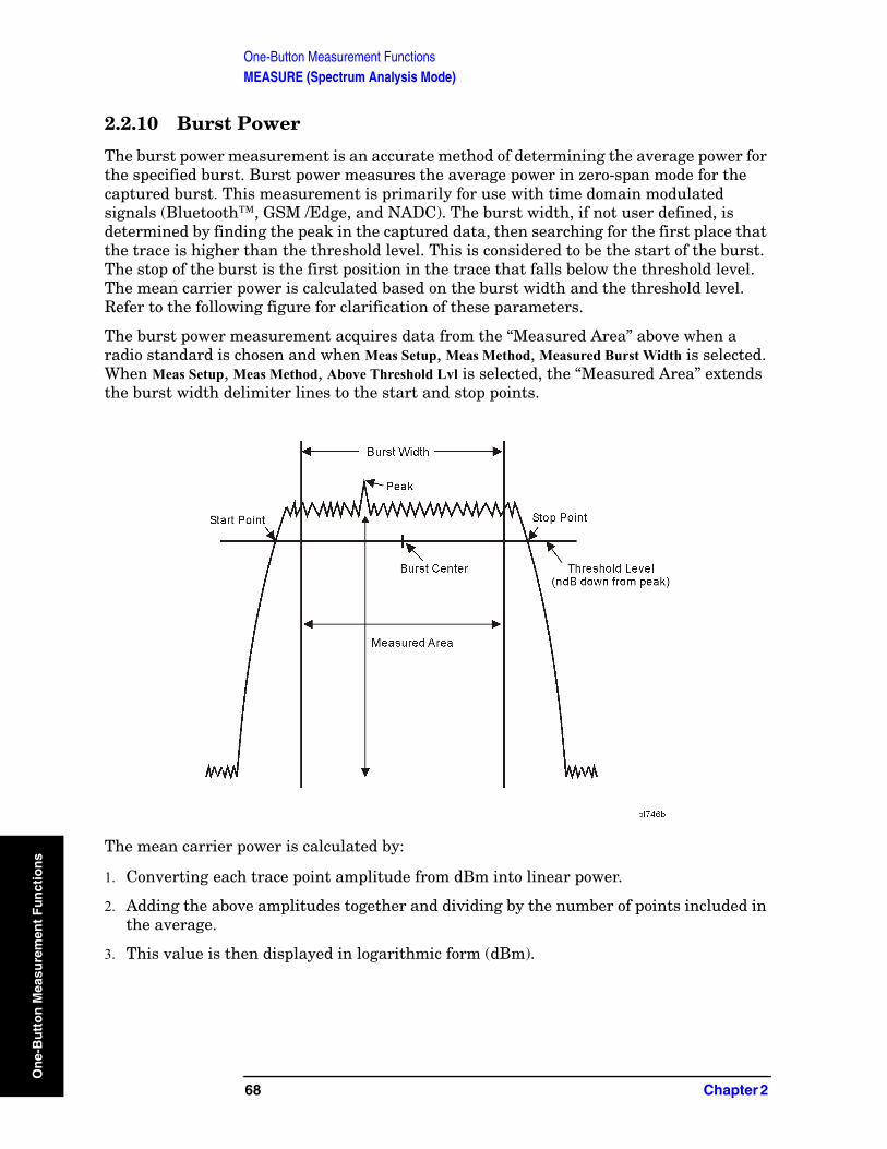
One-Button Measurement FunctionsMEASURE (Spectrum Analysis Mode)
On
e-B
utt
on
Mea
sure
men
t F
un
ctio
ns
2.2.10 Burst Power
The burst power measurement is an accurate method of determining the average power for the specified burst. Burst power measures the average power in zero-span mode for the captured burst. This measurement is primarily for use with time domain modulated signals (Bluetooth™, GSM /Edge, and NADC). The burst width, if not user defined, is determined by finding the peak in the captured data, then searching for the first place that the trace is higher than the threshold level. This is considered to be the start of the burst. The stop of the burst is the first position in the trace that falls below the threshold level. The mean carrier power is calculated based on the burst width and the threshold level. Refer to the following figure for clarification of these parameters.
The burst power measurement acquires data from the “Measured Area” above when a radio standard is chosen and when Meas Setup, Meas Method, Measured Burst Width is selected. When Meas Setup, Meas Method, Above Threshold Lvl is selected, the “Measured Area” extends the burst width delimiter lines to the start and stop points.
The mean carrier power is calculated by:
1. Converting each trace point amplitude from dBm into linear power.
2. Adding the above amplitudes together and dividing by the number of points included in the average.
3. This value is then displayed in logarithmic form (dBm).
68 Chapter 2
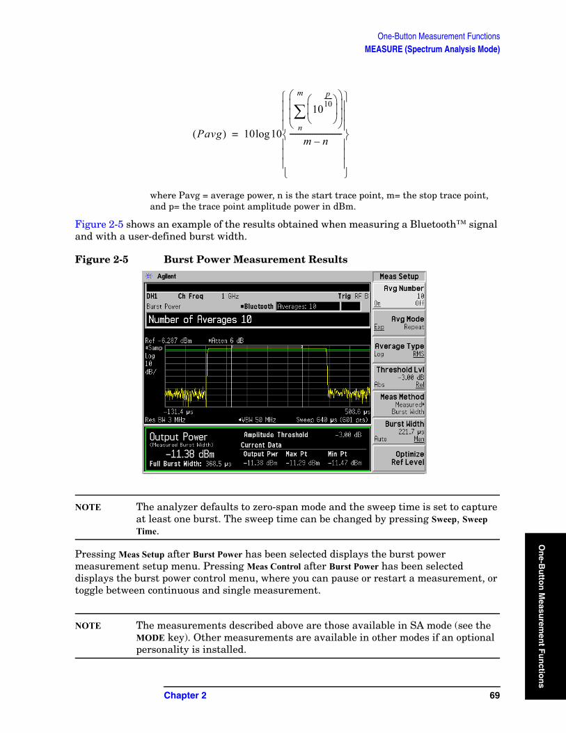
One-Button Measurement FunctionsMEASURE (Spectrum Analysis Mode)
On
e-Bu
tton
Measu
remen
t Fu
nctio
where Pavg = average power, n is the start trace point, m= the stop trace point, and p= the trace point amplitude power in dBm.
Figure 2-5 shows an example of the results obtained when measuring a Bluetooth™ signal and with a user-defined burst width.
Figure 2-5 Burst Power Measurement Results
NOTE The analyzer defaults to zero-span mode and the sweep time is set to capture at least one burst. The sweep time can be changed by pressing Sweep, Sweep Time.
Pressing Meas Setup after Burst Power has been selected displays the burst power measurement setup menu. Pressing Meas Control after Burst Power has been selected displays the burst power control menu, where you can pause or restart a measurement, or toggle between continuous and single measurement.
NOTE The measurements described above are those available in SA mode (see the MODE key). Other measurements are available in other modes if an optional personality is installed.
Pavg( ) 10 10
10p10------
⎝ ⎠⎜ ⎟⎛ ⎞
n
m
∑⎝ ⎠⎜ ⎟⎜ ⎟⎛ ⎞
m n–----------------------------
⎩ ⎭⎪ ⎪⎪ ⎪⎪ ⎪⎨ ⎬⎪ ⎪⎪ ⎪⎪ ⎪⎧ ⎫
log=
Chapter 2 69
ns
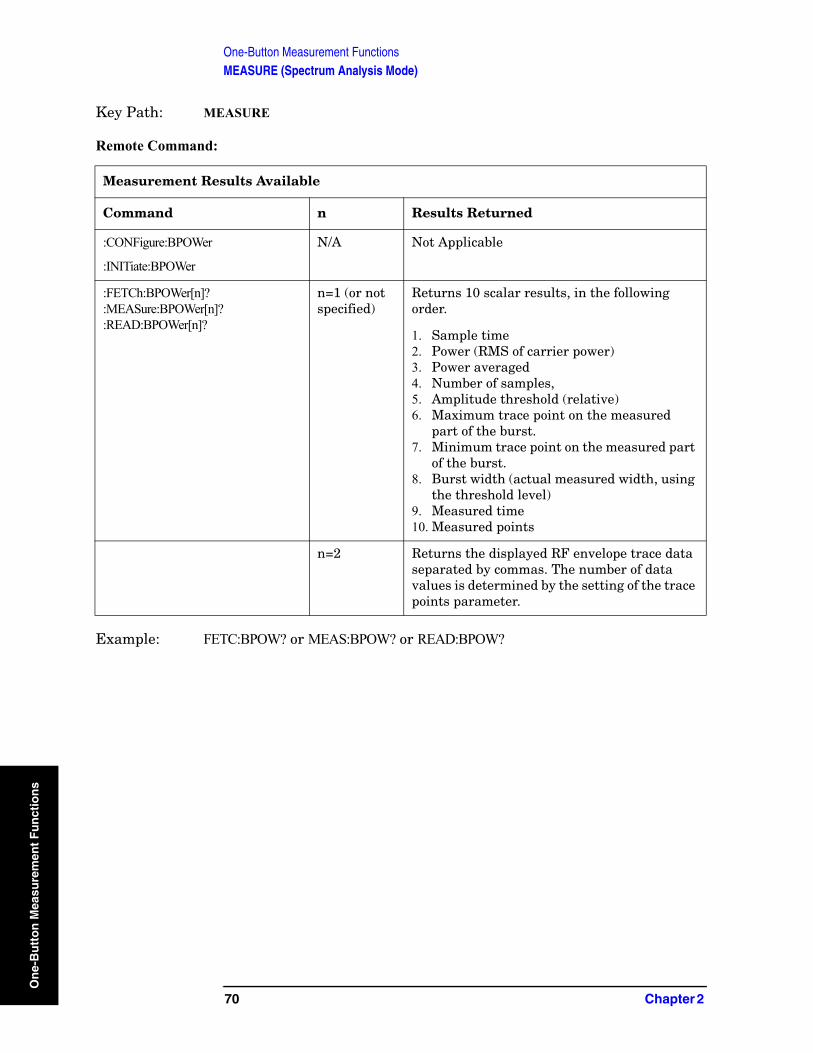
One-Button Measurement FunctionsMEASURE (Spectrum Analysis Mode)
On
e-B
utt
on
Mea
sure
men
t F
un
ctio
ns
Key Path: MEASURE
Remote Command:
Example: FETC:BPOW? or MEAS:BPOW? or READ:BPOW?
Measurement Results Available
Command n Results Returned
:CONFigure:BPOWer
:INITiate:BPOWer
N/A Not Applicable
:FETCh:BPOWer[n]?:MEASure:BPOWer[n]?:READ:BPOWer[n]?
n=1 (or not specified)
Returns 10 scalar results, in the following order.
1. Sample time2. Power (RMS of carrier power)3. Power averaged 4. Number of samples, 5. Amplitude threshold (relative)6. Maximum trace point on the measured
part of the burst.7. Minimum trace point on the measured part
of the burst.8. Burst width (actual measured width, using
the threshold level)9. Measured time10. Measured points
n=2 Returns the displayed RF envelope trace data separated by commas. The number of data values is determined by the setting of the trace points parameter.
70 Chapter 2
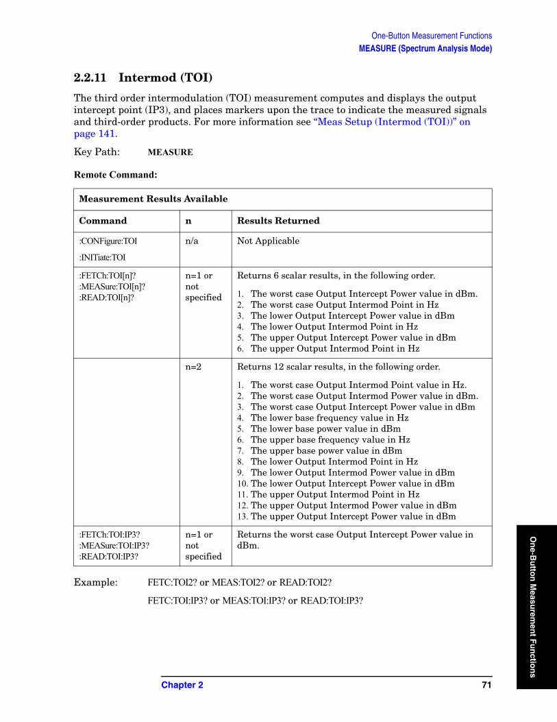
One-Button Measurement FunctionsMEASURE (Spectrum Analysis Mode)
On
e-Bu
tton
Measu
remen
t Fu
nctio
2.2.11 Intermod (TOI)
The third order intermodulation (TOI) measurement computes and displays the output intercept point (IP3), and places markers upon the trace to indicate the measured signals and third-order products. For more information see “Meas Setup (Intermod (TOI))” on page 141.
Key Path: MEASURE
Remote Command:
Example: FETC:TOI2? or MEAS:TOI2? or READ:TOI2?
FETC:TOI:IP3? or MEAS:TOI:IP3? or READ:TOI:IP3?
Measurement Results Available
Command n Results Returned
:CONFigure:TOI
:INITiate:TOI
n/a Not Applicable
:FETCh:TOI[n]?:MEASure:TOI[n]?:READ:TOI[n]?
n=1 or not specified
Returns 6 scalar results, in the following order.
1. The worst case Output Intercept Power value in dBm.2. The worst case Output Intermod Point in Hz3. The lower Output Intercept Power value in dBm4. The lower Output Intermod Point in Hz5. The upper Output Intercept Power value in dBm6. The upper Output Intermod Point in Hz
n=2 Returns 12 scalar results, in the following order.
1. The worst case Output Intermod Point value in Hz.2. The worst case Output Intermod Power value in dBm.3. The worst case Output Intercept Power value in dBm4. The lower base frequency value in Hz5. The lower base power value in dBm6. The upper base frequency value in Hz7. The upper base power value in dBm8. The lower Output Intermod Point in Hz9. The lower Output Intermod Power value in dBm10. The lower Output Intercept Power value in dBm11. The upper Output Intermod Point in Hz12. The upper Output Intermod Power value in dBm13. The upper Output Intercept Power value in dBm
:FETCh:TOI:IP3?:MEASure:TOI:IP3?:READ:TOI:IP3?
n=1 or not specified
Returns the worst case Output Intercept Power value in dBm.
Chapter 2 71
ns
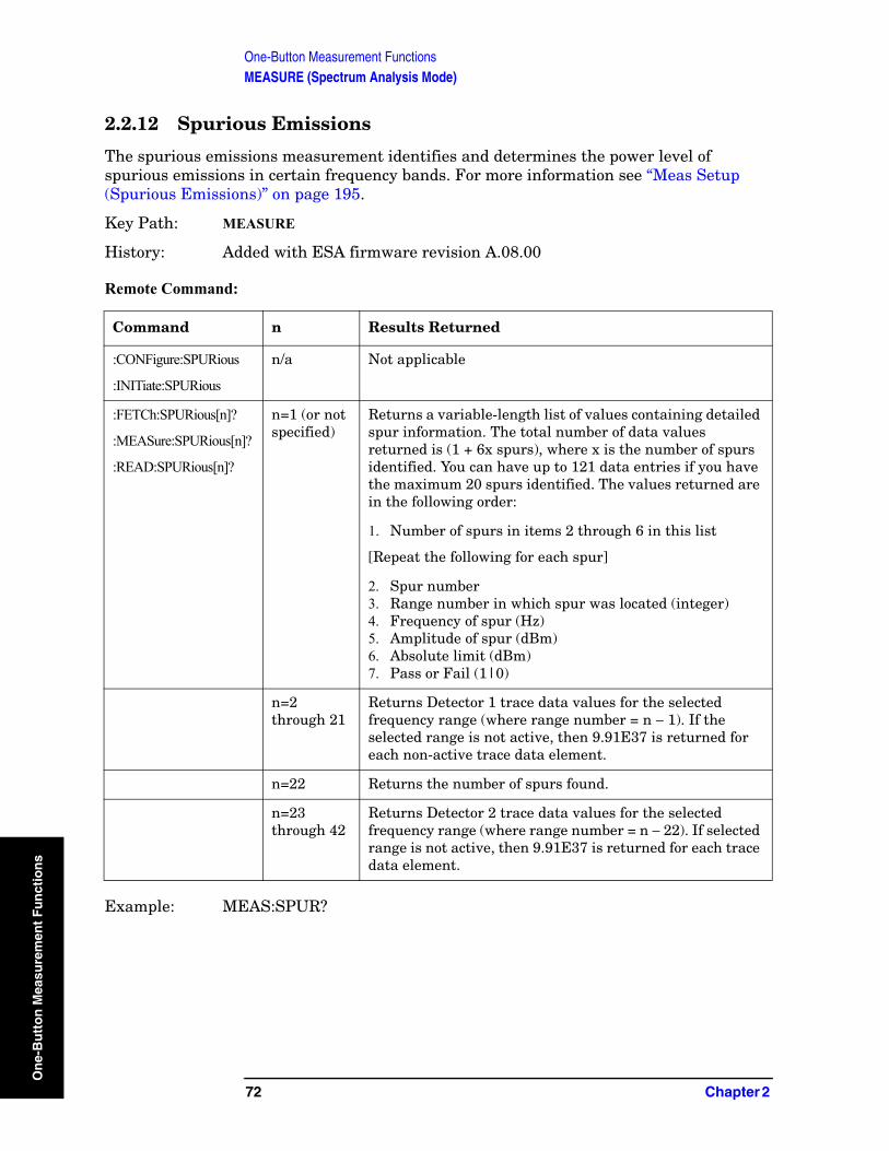
One-Button Measurement FunctionsMEASURE (Spectrum Analysis Mode)
On
e-B
utt
on
Mea
sure
men
t F
un
ctio
ns
2.2.12 Spurious Emissions
The spurious emissions measurement identifies and determines the power level of spurious emissions in certain frequency bands. For more information see “Meas Setup (Spurious Emissions)” on page 195.
Key Path: MEASURE
History: Added with ESA firmware revision A.08.00
Remote Command:
Example: MEAS:SPUR?
Command n Results Returned
:CONFigure:SPURious
:INITiate:SPURious
n/a Not applicable
:FETCh:SPURious[n]?
:MEASure:SPURious[n]?
:READ:SPURious[n]?
n=1 (or not specified)
Returns a variable-length list of values containing detailed spur information. The total number of data values returned is (1 + 6x spurs), where x is the number of spurs identified. You can have up to 121 data entries if you have the maximum 20 spurs identified. The values returned are in the following order:
1. Number of spurs in items 2 through 6 in this list
[Repeat the following for each spur]
2. Spur number3. Range number in which spur was located (integer)4. Frequency of spur (Hz)5. Amplitude of spur (dBm)6. Absolute limit (dBm)7. Pass or Fail (1|0)
n=2 through 21
Returns Detector 1 trace data values for the selected frequency range (where range number = n − 1). If the selected range is not active, then 9.91E37 is returned for each non-active trace data element.
n=22 Returns the number of spurs found.
n=23 through 42
Returns Detector 2 trace data values for the selected frequency range (where range number = n − 22). If selected range is not active, then 9.91E37 is returned for each trace data element.
72 Chapter 2
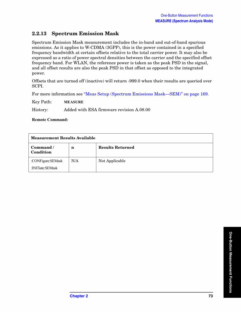
One-Button Measurement FunctionsMEASURE (Spectrum Analysis Mode)
On
e-Bu
tton
Measu
remen
t Fu
nctio
2.2.13 Spectrum Emission Mask
Spectrum Emission Mask measurement includes the in-band and out-of-band spurious emissions. As it applies to W-CDMA (3GPP), this is the power contained in a specified frequency bandwidth at certain offsets relative to the total carrier power. It may also be expressed as a ratio of power spectral densities between the carrier and the specified offset frequency band. For WLAN, the reference power is taken as the peak PSD in the signal, and all offset results are also the peak PSD in that offset as opposed to the integrated power.
Offsets that are turned off (inactive) will return -999.0 when their results are queried over SCPI.
For more information see “Meas Setup (Spectrum Emissions Mask—SEM)” on page 169.
Key Path: MEASURE
History: Added with ESA firmware revision A.08.00
Remote Command:
Measurement Results Available
Command / Condition
n Results Returned
:CONFigure:SEMask
:INITiate:SEMask
N/A Not Applicable
Chapter 2 73
ns
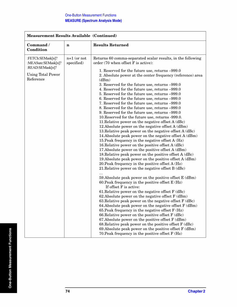
One-Button Measurement FunctionsMEASURE (Spectrum Analysis Mode)
On
e-B
utt
on
Mea
sure
men
t F
un
ctio
ns
:FETCh:SEMask[n]?:MEASure:SEMask[n]?:READ:SEMask[n]?
Using Total Power Reference
n=1 (or not specified)
Returns 60 comma-separated scalar results, in the following order (70 when offset F is active):
1. Reserved for the future use, returns –999.02. Absolute power at the center frequency (reference) area (dBm)3. Reserved for the future use, returns –999.04. Reserved for the future use, returns –999.05. Reserved for the future use, returns –999.06. Reserved for the future use, returns –999.07. Reserved for the future use, returns –999.08. Reserved for the future use, returns –999.09. Reserved for the future use, returns –999.010.Reserved for the future use, returns -999.0.11.Relative power on the negative offset A (dBc)12.Absolute power on the negative offset A (dBm)13.Relative peak power on the negative offset A (dBc)14.Absolute peak power on the negative offset A (dBm)15.Peak frequency in the negative offset A (Hz)16.Relative power on the positive offset A (dBc)17.Absolute power on the positive offset A (dBm)18.Relative peak power on the positive offset A (dBc)19.Absolute peak power on the positive offset A (dBm)20.Peak frequency in the positive offset A (Hz)21.Relative power on the negative offset B (dBc)…59.Absolute peak power on the positive offset E (dBm)60.Peak frequency in the positive offset E (Hz)
If offset F is active:61.Relative power on the negative offset F (dBc)62.Absolute power on the negative offset F (dBm)63.Relative peak power on the negative offset F (dBc)64.Absolute peak power on the negative offset F (dBm)65.Peak frequency in the negative offset F (Hz)66.Relative power on the positive offset F (dBc)67.Absolute power on the positive offset F (dBm)68.Relative peak power on the positive offset F (dBc)69.Absolute peak power on the positive offset F (dBm)70.Peak frequency in the positive offset F (Hz)
Measurement Results Available (Continued)
Command / Condition
n Results Returned
74 Chapter 2
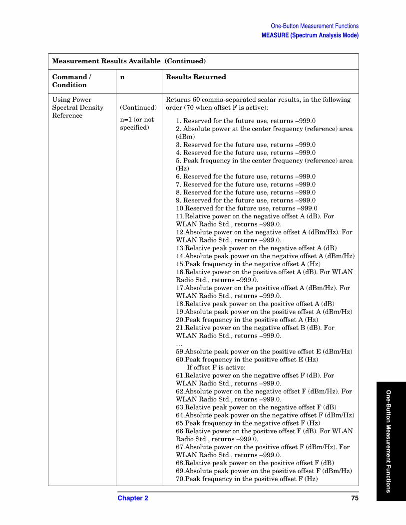
One-Button Measurement FunctionsMEASURE (Spectrum Analysis Mode)
On
e-Bu
tton
Measu
remen
t Fu
nctio
Using Power Spectral Density Reference
(Continued)
n=1 (or not specified)
Returns 60 comma-separated scalar results, in the following order (70 when offset F is active):
1. Reserved for the future use, returns –999.02. Absolute power at the center frequency (reference) area (dBm)3. Reserved for the future use, returns –999.04. Reserved for the future use, returns –999.05. Peak frequency in the center frequency (reference) area (Hz)6. Reserved for the future use, returns –999.07. Reserved for the future use, returns –999.08. Reserved for the future use, returns –999.09. Reserved for the future use, returns –999.010.Reserved for the future use, returns –999.011.Relative power on the negative offset A (dB). For WLAN Radio Std., returns –999.0.12.Absolute power on the negative offset A (dBm/Hz). For WLAN Radio Std., returns –999.0.13.Relative peak power on the negative offset A (dB)14.Absolute peak power on the negative offset A (dBm/Hz)15.Peak frequency in the negative offset A (Hz)16.Relative power on the positive offset A (dB). For WLAN Radio Std., returns –999.0.17.Absolute power on the positive offset A (dBm/Hz). For WLAN Radio Std., returns –999.0.18.Relative peak power on the positive offset A (dB)19.Absolute peak power on the positive offset A (dBm/Hz) 20.Peak frequency in the positive offset A (Hz)21.Relative power on the negative offset B (dB). For WLAN Radio Std., returns –999.0.…59.Absolute peak power on the positive offset E (dBm/Hz)60.Peak frequency in the positive offset E (Hz)
If offset F is active:61.Relative power on the negative offset F (dB). For WLAN Radio Std., returns –999.0.62.Absolute power on the negative offset F (dBm/Hz). For WLAN Radio Std., returns –999.0.63.Relative peak power on the negative offset F (dB)64.Absolute peak power on the negative offset F (dBm/Hz)65.Peak frequency in the negative offset F (Hz)66.Relative power on the positive offset F (dB). For WLAN Radio Std., returns –999.0.67.Absolute power on the positive offset F (dBm/Hz). For WLAN Radio Std., returns –999.0.68.Relative peak power on the positive offset F (dB)69.Absolute peak power on the positive offset F (dBm/Hz)70.Peak frequency in the positive offset F (Hz)
Measurement Results Available (Continued)
Command / Condition
n Results Returned
Chapter 2 75
ns
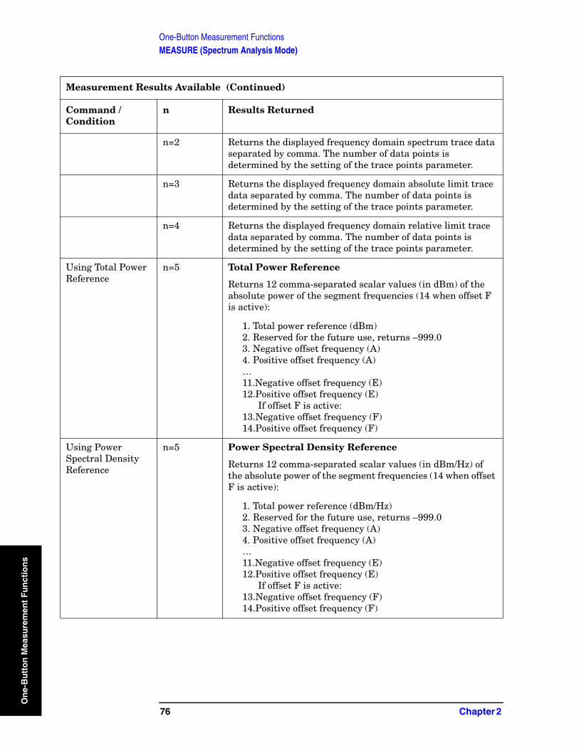
One-Button Measurement FunctionsMEASURE (Spectrum Analysis Mode)
On
e-B
utt
on
Mea
sure
men
t F
un
ctio
ns
n=2 Returns the displayed frequency domain spectrum trace data separated by comma. The number of data points is determined by the setting of the trace points parameter.
n=3 Returns the displayed frequency domain absolute limit trace data separated by comma. The number of data points is determined by the setting of the trace points parameter.
n=4 Returns the displayed frequency domain relative limit trace data separated by comma. The number of data points is determined by the setting of the trace points parameter.
Using Total Power Reference
n=5 Total Power Reference
Returns 12 comma-separated scalar values (in dBm) of the absolute power of the segment frequencies (14 when offset F is active):
1. Total power reference (dBm)2. Reserved for the future use, returns –999.03. Negative offset frequency (A)4. Positive offset frequency (A)…11.Negative offset frequency (E)12.Positive offset frequency (E)
If offset F is active:13.Negative offset frequency (F)14.Positive offset frequency (F)
Using Power Spectral Density Reference
n=5 Power Spectral Density Reference
Returns 12 comma-separated scalar values (in dBm/Hz) of the absolute power of the segment frequencies (14 when offset F is active):
1. Total power reference (dBm/Hz)2. Reserved for the future use, returns –999.03. Negative offset frequency (A)4. Positive offset frequency (A)…11.Negative offset frequency (E)12.Positive offset frequency (E)
If offset F is active:13.Negative offset frequency (F)14.Positive offset frequency (F)
Measurement Results Available (Continued)
Command / Condition
n Results Returned
76 Chapter 2
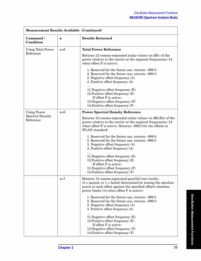
One-Button Measurement FunctionsMEASURE (Spectrum Analysis Mode)
On
e-Bu
tton
Measu
remen
t Fu
nctio
Using Total Power Reference
n=6 Total Power Reference
Returns 12 comma-separated scalar values (in dBc) of the power relative to the carrier at the segment frequencies (14 when offset F is active):
1. Reserved for the future use, returns –999.02. Reserved for the future use, returns –999.03. Negative offset frequency (A)4. Positive offset frequency (A)…11.Negative offset frequency (E)12.Positive offset frequency (E)
If offset F is active:13.Negative offset frequency (F)14.Positive offset frequency (F)
Using Power Spectral Density Reference
n=6 Power Spectral Density Reference
Returns 12 comma-separated scalar values (in dBc/Hz) of the power relative to the carrier at the segment frequencies (14 when offset F is active). Returns –999.0 for the offsets in WLAN standard:
1. Reserved for the future use, returns –999.02. Reserved for the future use, returns –999.03. Negative offset frequency (A)4. Positive offset frequency (A)…11.Negative offset frequency (E)12.Positive offset frequency (E)
If offset F is active:13.Negative offset frequency (F)14.Positive offset frequency (F)
n=7 Returns 12 comma-separated pass/fail test results (0 = passed, or 1 = failed) determined by testing the absolute power in each offset against the specified offset’s absolute power limits (14 when offset F is active):
1. Reserved for the future use, returns –999.02. Reserved for the future use, returns –999.03. Negative offset frequency (A)4. Positive offset frequency (A)…11.Negative offset frequency (E)12.Positive offset frequency (E)
If offset F is active:13.Negative offset frequency (F)14.Positive offset frequency (F)
Measurement Results Available (Continued)
Command / Condition
n Results Returned
Chapter 2 77
ns
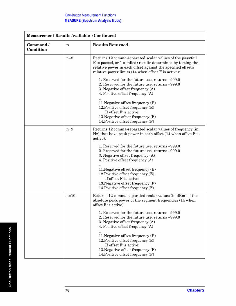
One-Button Measurement FunctionsMEASURE (Spectrum Analysis Mode)
On
e-B
utt
on
Mea
sure
men
t F
un
ctio
ns
n=8 Returns 12 comma-separated scalar values of the pass/fail (0 = passed, or 1 = failed) results determined by testing the relative power in each offset against the specified offset’s relative power limits (14 when offset F is active):
1. Reserved for the future use, returns –999.02. Reserved for the future use, returns –999.03. Negative offset frequency (A)4. Positive offset frequency (A)…11.Negative offset frequency (E)12.Positive offset frequency (E)
If offset F is active:13.Negative offset frequency (F)14.Positive offset frequency (F)
n=9 Returns 12 comma-separated scalar values of frequency (in Hz) that have peak power in each offset (14 when offset F is active):
1. Reserved for the future use, returns –999.02. Reserved for the future use, returns –999.03. Negative offset frequency (A)4. Positive offset frequency (A)…11.Negative offset frequency (E)12.Positive offset frequency (E)
If offset F is active:13.Negative offset frequency (F)14.Positive offset frequency (F)
n=10 Returns 12 comma-separated scalar values (in dBm) of the absolute peak power of the segment frequencies (14 when offset F is active):
1. Reserved for the future use, returns –999.02. Reserved for the future use, returns –999.03. Negative offset frequency (A)4. Positive offset frequency (A)…11.Negative offset frequency (E)12.Positive offset frequency (E)
If offset F is active:13.Negative offset frequency (F)14.Positive offset frequency (F)
Measurement Results Available (Continued)
Command / Condition
n Results Returned
78 Chapter 2
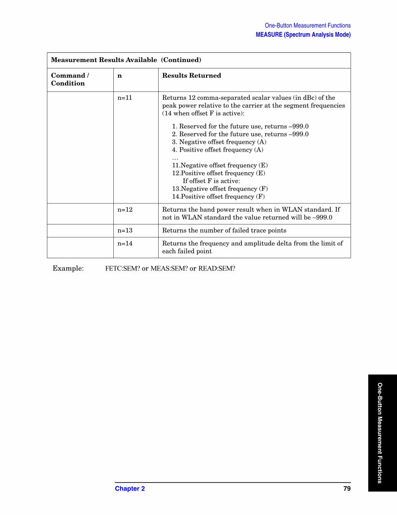
One-Button Measurement FunctionsMEASURE (Spectrum Analysis Mode)
On
e-Bu
tton
Measu
remen
t Fu
nctio
Example: FETC:SEM? or MEAS:SEM? or READ:SEM?
n=11 Returns 12 comma-separated scalar values (in dBc) of the peak power relative to the carrier at the segment frequencies (14 when offset F is active):
1. Reserved for the future use, returns –999.02. Reserved for the future use, returns –999.03. Negative offset frequency (A)4. Positive offset frequency (A)…11.Negative offset frequency (E)12.Positive offset frequency (E)
If offset F is active:13.Negative offset frequency (F)14.Positive offset frequency (F)
n=12 Returns the band power result when in WLAN standard. If not in WLAN standard the value returned will be –999.0
n=13 Returns the number of failed trace points
n=14 Returns the frequency and amplitude delta from the limit of each failed point
Measurement Results Available (Continued)
Command / Condition
n Results Returned
Chapter 2 79
ns

One-Button Measurement FunctionsMEASURE (Spectrum Analysis Mode)
On
e-B
utt
on
Mea
sure
men
t F
un
ctio
ns
80 Chapter 2
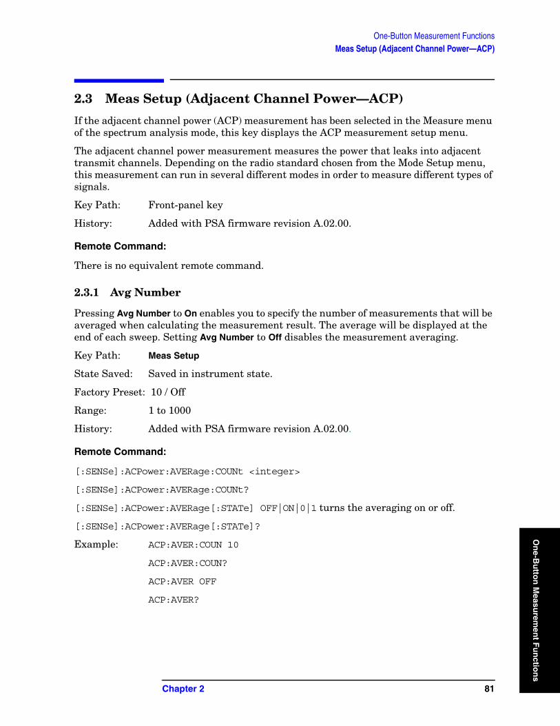
One-Button Measurement FunctionsMeas Setup (Adjacent Channel Power—ACP)
On
e-Bu
tton
Measu
remen
t Fu
nctio
2.3 Meas Setup (Adjacent Channel Power—ACP)
If the adjacent channel power (ACP) measurement has been selected in the Measure menu of the spectrum analysis mode, this key displays the ACP measurement setup menu.
The adjacent channel power measurement measures the power that leaks into adjacent transmit channels. Depending on the radio standard chosen from the Mode Setup menu, this measurement can run in several different modes in order to measure different types of signals.
Key Path: Front-panel key
History: Added with PSA firmware revision A.02.00.
Remote Command:
There is no equivalent remote command.
2.3.1 Avg Number
Pressing Avg Number to On enables you to specify the number of measurements that will be averaged when calculating the measurement result. The average will be displayed at the end of each sweep. Setting Avg Number to Off disables the measurement averaging.
Key Path: Meas Setup
State Saved: Saved in instrument state.
Factory Preset: 10 / Off
Range: 1 to 1000
History: Added with PSA firmware revision A.02.00.
Remote Command:
[:SENSe]:ACPower:AVERage:COUNt <integer>
[:SENSe]:ACPower:AVERage:COUNt?
[:SENSe]:ACPower:AVERage[:STATe] OFF|ON|0|1 turns the averaging on or off.
[:SENSe]:ACPower:AVERage[:STATe]?
Example: ACP:AVER:COUN 10
ACP:AVER:COUN?
ACP:AVER OFF
ACP:AVER?
Chapter 2 81
ns
One-Button Measurement FunctionsMeas Setup (Adjacent Channel Power—ACP)
On
e-B
utt
on
Mea
sure
men
t F
un
ctio
ns
2.3.2 Avg Mode
Press Avg Mode to select the type of termination control used for the averaging function as either Exp or Repeat. This determines the averaging action after the specified number of measurements (average count) is reached.
• EXP (Exponential Averaging mode)—When you set Avg Mode to Exp, each successive data acquisition after the average count is reached is exponentially weighted and combined with the existing average. Exponential averaging weights new data more than old data, which facilitates tracking of slow-changing signals. The average will be displayed at the end of each sweep.
• Repeat—When you set Avg Mode to Repeat, after reaching the average count, all previous result data is cleared and the average count is set back to 1.
Key Path: Meas Setup
State Saved: Saved in instrument state.
Factory Preset: EXPonential
History: Added with PSA firmware revision A.02.00.
Remote Command:
[:SENSe]:ACPower:AVERage:TCONrol EXPonential|REPeat
[:SENSe]:ACPower:AVERage:TCONrol?
Example: ACP:AVG:TCON EXP
ACP:AVG:TCON?
2.3.3 Chan Integ BW
Press Chan Integ BW to specify the range of integration used in calculating the power in the main channel.
Key Path: Meas Setup
Key Notes: If RRC Filter is on, the actual integration bandwidth used is the displayed integration bandwidth multiplied by (1 + Filter Alpha).
State Saved: Saved in instrument state.
Factory Preset: 2.0 MHz or as defined by the selected radio standard.
Default Terminator: Hz
Knob Increment: Span/50 if non-zero span.
RBW/100 if zero span.
Step Key Increment: RBW if CF Step is set to Auto with zero span.
82 Chapter 2

One-Button Measurement FunctionsMeas Setup (Adjacent Channel Power—ACP)
On
e-Bu
tton
Measu
remen
t Fu
nctio
Span/10 if CF Step is set to Auto with non-zero span.
CF Step if CF Step is set to Manual.
Range: 300 Hz to 500 MHz. Depends on the adjacent-channel settings and the minimum and maximum analyzer span.
History: Added with PSA firmware revision A.02.00.
Remote Command:
[:SENSe]:ACPower:BANDwidth|BWIDth:INTegration <freq>
[:SENSe]:ACPower:BANDwidth|BWIDth:INTegration?
Example: ACP:BWID:INT 5E6
ACP:BWID:INT?
2.3.4 Offset/Limits
Accesses menu keys that allow you to configure the offsets for the ACP measurement.
Key Path: Meas Setup
2.3.4.1 Offset
Selects the offset the menu keys will affect. Press Offset until the letter of the desired offset is underlined.
Key Path: Meas Setup, Offset Setup
State Saved: Saved in instrument state.
Factory Preset: A
History: Added with PSA firmware revision A.02.00.
Remote Command:
There is no remote command for this function.
2.3.4.2 Offset Freq or Edge Freq
Enables you to set the frequency difference from the center of the main channel to the center of the offset for a maximum of 6 offsets (labeled A-F). It also allows you to turn on/off the offsets that you want to measure.
NOTE This key label changes to Edge Freq when IS-95C, cdma2000 MC-1X, cdma2000 MC-3X, or cdma2000 DS is selected.
Chapter 2 83
ns
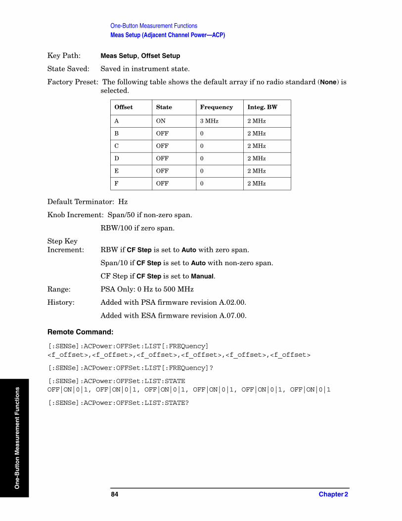
One-Button Measurement FunctionsMeas Setup (Adjacent Channel Power—ACP)
On
e-B
utt
on
Mea
sure
men
t F
un
ctio
ns
Key Path: Meas Setup, Offset Setup
State Saved: Saved in instrument state.
Factory Preset: The following table shows the default array if no radio standard (None) is selected.
Default Terminator: Hz
Knob Increment: Span/50 if non-zero span.
RBW/100 if zero span.
Step Key Increment: RBW if CF Step is set to Auto with zero span.
Span/10 if CF Step is set to Auto with non-zero span.
CF Step if CF Step is set to Manual.
Range: PSA Only: 0 Hz to 500 MHz
History: Added with PSA firmware revision A.02.00.
Added with ESA firmware revision A.07.00.
Remote Command:
[:SENSe]:ACPower:OFFSet:LIST[:FREQuency] <f_offset>,<f_offset>,<f_offset>,<f_offset>,<f_offset>,<f_offset>
[:SENSe]:ACPower:OFFSet:LIST[:FREQuency]?
[:SENSe]:ACPower:OFFSet:LIST:STATE OFF|ON|0|1, OFF|ON|0|1, OFF|ON|0|1, OFF|ON|0|1, OFF|ON|0|1, OFF|ON|0|1
[:SENSe]:ACPower:OFFSet:LIST:STATE?
Offset State Frequency Integ. BW
A ON 3 MHz 2 MHz
B OFF 0 2 MHz
C OFF 0 2 MHz
D OFF 0 2 MHz
E OFF 0 2 MHz
F OFF 0 2 MHz
84 Chapter 2
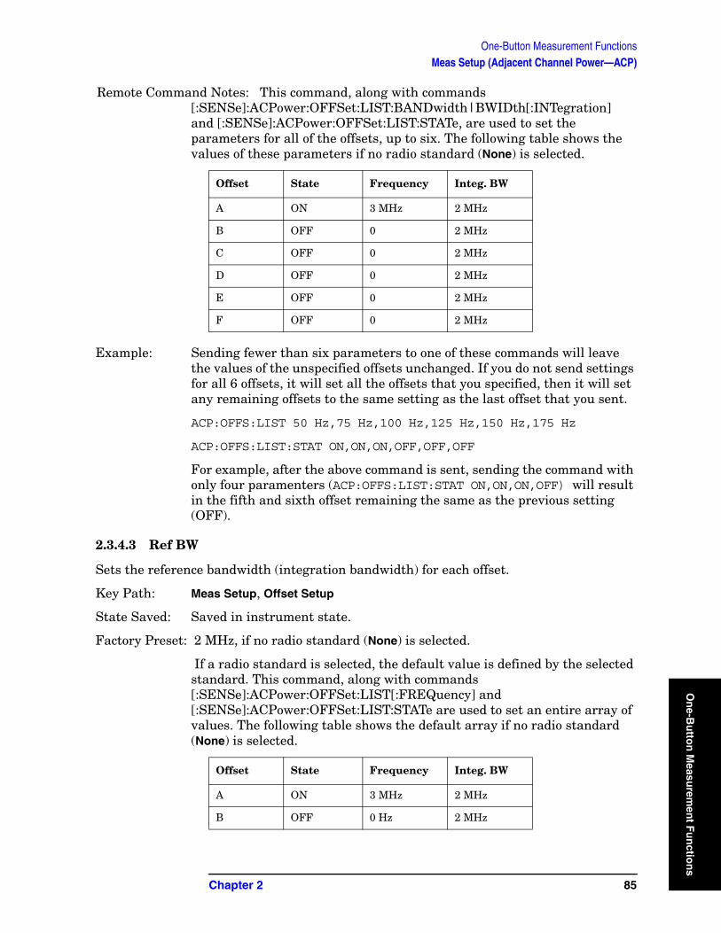
One-Button Measurement FunctionsMeas Setup (Adjacent Channel Power—ACP)
On
e-Bu
tton
Measu
remen
t Fu
nctio
Remote Command Notes: This command, along with commands [:SENSe]:ACPower:OFFSet:LIST:BANDwidth|BWIDth[:INTegration] and [:SENSe]:ACPower:OFFSet:LIST:STATe, are used to set the parameters for all of the offsets, up to six. The following table shows the values of these parameters if no radio standard (None) is selected.
Example: Sending fewer than six parameters to one of these commands will leave the values of the unspecified offsets unchanged. If you do not send settings for all 6 offsets, it will set all the offsets that you specified, then it will set any remaining offsets to the same setting as the last offset that you sent.
ACP:OFFS:LIST 50 Hz,75 Hz,100 Hz,125 Hz,150 Hz,175 Hz
ACP:OFFS:LIST:STAT ON,ON,ON,OFF,OFF,OFF
For example, after the above command is sent, sending the command with only four paramenters (ACP:OFFS:LIST:STAT ON,ON,ON,OFF) will result in the fifth and sixth offset remaining the same as the previous setting (OFF).
2.3.4.3 Ref BW
Sets the reference bandwidth (integration bandwidth) for each offset.
Key Path: Meas Setup, Offset Setup
State Saved: Saved in instrument state.
Factory Preset: 2 MHz, if no radio standard (None) is selected.
If a radio standard is selected, the default value is defined by the selected standard. This command, along with commands [:SENSe]:ACPower:OFFSet:LIST[:FREQuency] and [:SENSe]:ACPower:OFFSet:LIST:STATe are used to set an entire array of values. The following table shows the default array if no radio standard (None) is selected.
Offset State Frequency Integ. BW
A ON 3 MHz 2 MHz
B OFF 0 2 MHz
C OFF 0 2 MHz
D OFF 0 2 MHz
E OFF 0 2 MHz
F OFF 0 2 MHz
Offset State Frequency Integ. BW
A ON 3 MHz 2 MHz
B OFF 0 Hz 2 MHz
Chapter 2 85
ns
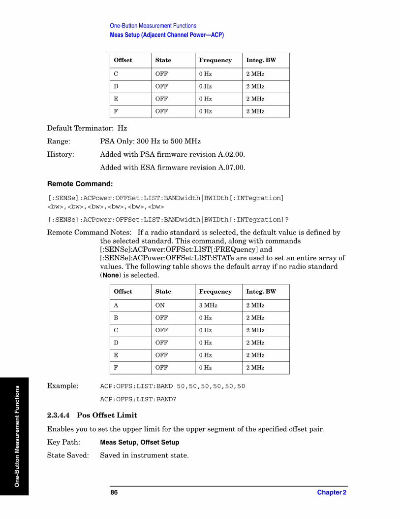
One-Button Measurement FunctionsMeas Setup (Adjacent Channel Power—ACP)
On
e-B
utt
on
Mea
sure
men
t F
un
ctio
ns
Default Terminator: Hz
Range: PSA Only: 300 Hz to 500 MHz
History: Added with PSA firmware revision A.02.00.
Added with ESA firmware revision A.07.00.
Remote Command:
[:SENSe]:ACPower:OFFSet:LIST:BANDwidth|BWIDth[:INTegration] <bw>,<bw>,<bw>,<bw>,<bw>,<bw>
[:SENSe]:ACPower:OFFSet:LIST:BANDwidth|BWIDth[:INTegration]?
Remote Command Notes: If a radio standard is selected, the default value is defined by the selected standard. This command, along with commands [:SENSe]:ACPower:OFFSet:LIST[:FREQuency] and [:SENSe]:ACPower:OFFSet:LIST:STATe are used to set an entire array of values. The following table shows the default array if no radio standard (None) is selected.
Example: ACP:OFFS:LIST:BAND 50,50,50,50,50,50
ACP:OFFS:LIST:BAND?
2.3.4.4 Pos Offset Limit
Enables you to set the upper limit for the upper segment of the specified offset pair.
Key Path: Meas Setup, Offset Setup
State Saved: Saved in instrument state.
C OFF 0 Hz 2 MHz
D OFF 0 Hz 2 MHz
E OFF 0 Hz 2 MHz
F OFF 0 Hz 2 MHz
Offset State Frequency Integ. BW
A ON 3 MHz 2 MHz
B OFF 0 Hz 2 MHz
C OFF 0 Hz 2 MHz
D OFF 0 Hz 2 MHz
E OFF 0 Hz 2 MHz
F OFF 0 Hz 2 MHz
Offset State Frequency Integ. BW
86 Chapter 2
One-Button Measurement FunctionsMeas Setup (Adjacent Channel Power—ACP)
On
e-Bu
tton
Measu
remen
t Fu
nctio
Factory Preset: 0.00 dB
Default Terminator: dB
Range: –200 dB to 200 dB
History: Added with PSA firmware revision A.02.00.
Added with ESA firmware revision A.08.00.
Remote Command:
:CALCulate:ACPower:OFFSet:LIST:LIMit:POSitive[:UPPer]:DATA <rel_power>,<rel_power>,<rel_power>,<rel_power>,<rel_power>,<rel_power>
:CALCulate:ACPower:OFFSet:LIST:LIMit:POSitive[:UPPer]:DATA?
Example: CALC:ACP:OFFS:LIST:LIM:POS:DATA 10,10,10,10,10,10
CALC:ACP:OFFS:LIST:LIM:POS:DATA?
2.3.4.5 Neg Offset Limit
Enables you to set the upper limit for the lower segment of the specified offset pair.
Key Path: Meas Setup, Offset Setup
State Saved: Saved in instrument state.
Factory Preset: 0.00 dB
Default Terminator: dB
Range: –200 dB to 200 dB
History: Added with PSA firmware revision A.02.00.
Added with ESA firmware revision A.08.00.
Remote Command:
:CALCulate:ACPower:OFFSet:LIST:LIMit:NEGative[:UPPer]:DATA <rel_power>,<rel_power>,<rel_power>,<rel_power>,<rel_power>,<rel_power>
:CALCulate:ACPower:OFFSet:LIST:LIMit:NEGative[:UPPer]:DATA?
Example: CALC:ACP:OFFS:LIST:LIM:NEG:DATA −50,−50,−50,−50,−50,−50
CALC:ACP:OFFS:LIST:LIM:NEG:DATA?
2.3.5 Meas Type
Press Meas Type to specify the reference for the measurement, either Total Pwr Ref or PSD Ref. Relative values can be displayed referenced to either the total power (Total Pwr Ref) or the power spectral density (PSD Ref) measured in the main channel.
Key Path: Meas Setup
State Saved: Saved in instrument state.
Chapter 2 87
ns

One-Button Measurement FunctionsMeas Setup (Adjacent Channel Power—ACP)
On
e-B
utt
on
Mea
sure
men
t F
un
ctio
ns
Factory Preset: Total Pwr Ref
History: Added with PSA firmware revision A.02.00.
Added with ESA firmware revision A.07.00.
Remote Command:
[:SENSe]:ACPower:TYPE PSDRef|TPRef
[:SENSe]:ACPower:TYPE?
Example: ACP:TYPE PSDR
ACP:TYPE?
2.3.6 Optimize Ref Level
Sets the input attenuator and reference level to optimize the robustness of the measurement, in which it is free from errors due to input compression and log amp range limitations. The input attenuator setting will not necessarily give the optimum dynamic range, nor the optimum accuracy. No single setting can optimize both, and the optimum setting often depends on the signal characteristics.
NOTE There will always be a minimum of 2 dB for PSA or 5 dB for ESA of attenuation set to protect the analyzer input.
Key Path: Meas Setup
State Saved: Not saved.
History: Added with PSA firmware revision A.02.00.
Remote Command:
[:SENSe]:POWer[:RF]:RANGe:AUTO ONCE
Example: POW:RANG:AUTO ONCE
2.3.7 Method
Enables you to set the measurement method. The resolution bandwidth method is most useful for measuring cdmaOne and cdma2000 signals. The integration bandwidth method is preferred for other signals.
NOTE ESA Only:
This key toggles to select either the integration bandwidth method (IBW) or the resolution bandwidth method (RBW).
Key Path:. Meas Setup
State Saved:. Saved in instrument state.
88 Chapter 2
One-Button Measurement FunctionsMeas Setup (Adjacent Channel Power—ACP)
On
e-Bu
tton
Measu
remen
t Fu
nctio
Factory Preset:. IBW
History:. Added with PSA firmware revision A.02.00.
Added with ESA firmware revision A.08.00.
Remote Command:
[:SENSe]:ACPower:METHod IBW|RBW|FAST
[:SENSe]:ACPower:METHod?
Remote Command Notes: . ESA Only: Fast is not an available option.
Example:. ACP:METH RBW
ACP:METH?
2.3.7.1 IBW (PSA Only)
Sets the measurement control method to IBW.
Key Type:. 1 of N menu
Key Path:. Meas Setup, Method
History:. Modified with PSA firmware revision A.06.00
Remote Command:
Use[:SENSe]:ACPower:METHod See “Method” on page 88.
Example: ACP:METH IBW.
2.3.7.2 RBW (PSA Only)
Sets the measurement control method to RBW.
Key Type:. 1 of N menu
Key Path:. Meas Setup, Method
History:. Modified with PSA firmware revision A.06.00
Remote Command:
Use[:SENSe]:ACPower:METHod See “Method” on page 88.
Example: ACP:METH RBW.
2.3.7.3 Fast (PSA Only)
Sets the measurement control method to Fast. When this method is selected, the 5 point ACLR measurement method is used. The following parameters are configured to allow the measurement to be made. This method is only available for the 3GPP W-CDMA radio standard, this key will be disabled for all other radio standards.
NOTE The current function values are not saved when fast method is turned on.
Chapter 2 89
ns
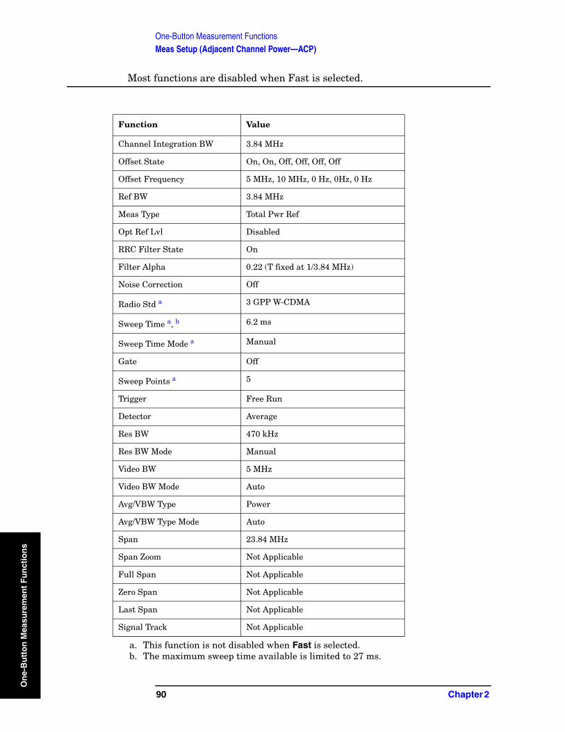
One-Button Measurement FunctionsMeas Setup (Adjacent Channel Power—ACP)
On
e-B
utt
on
Mea
sure
men
t F
un
ctio
ns
Most functions are disabled when Fast is selected.
Function Value
Channel Integration BW 3.84 MHz
Offset State On, On, Off, Off, Off, Off
Offset Frequency 5 MHz, 10 MHz, 0 Hz, 0Hz, 0 Hz
Ref BW 3.84 MHz
Meas Type Total Pwr Ref
Opt Ref Lvl Disabled
RRC Filter State On
Filter Alpha 0.22 (T fixed at 1/3.84 MHz)
Noise Correction Off
Radio Std a
a. This function is not disabled when Fast is selected.
3 GPP W-CDMA
Sweep Time a, b
b. The maximum sweep time available is limited to 27 ms.
6.2 ms
Sweep Time Mode a Manual
Gate Off
Sweep Points a 5
Trigger Free Run
Detector Average
Res BW 470 kHz
Res BW Mode Manual
Video BW 5 MHz
Video BW Mode Auto
Avg/VBW Type Power
Avg/VBW Type Mode Auto
Span 23.84 MHz
Span Zoom Not Applicable
Full Span Not Applicable
Zero Span Not Applicable
Last Span Not Applicable
Signal Track Not Applicable
90 Chapter 2
One-Button Measurement FunctionsMeas Setup (Adjacent Channel Power—ACP)
On
e-Bu
tton
Measu
remen
t Fu
nctio
Key Type: 1 of N menu
Key Path:. Meas Setup, Method
History:. Added with PSA firmware revision A.06.00
Remote Command:
Use[:SENSe]:ACPower:METHod See “Method” on page 88.
Example: ACP:METH FAST.
The following is an example of how to optimize speed.
FORM:DATA REAL,32CAL:AUTO OFFCONF:ACPRAD:STAN W3GPPSWE:POIN 601ACP:AVER OFFACP:CARR:AUTO ONACP:FILT ONACP:FILT:ALPH 0.22ACP:CORR:NOISE OFFPOW:RANG:AUTO ONCEACP:METH FASTINIT:CONT OFFDISP:ENAB OFFINIT:ACP
2.3.8 Total Pwr Ref
Enables you to set the adjacent channel power reference to automatic or manual when Meas Type is set to Total Pwr Ref. When set to automatic, the carrier power result reflects the measured power value in the carrier. When set to manual, the last measured value is captured and held, or may be entered by the user. Relative values are displayed, referenced to the total power measured in the main channel.
Key Path: Meas Setup
State Saved: Saved in instrument state.
Factory Preset: Auto, Measured carrier power value
Terminators: dBm
Default Terminator: dBm
Range: –200 dBm to 200 dBm
History: Added with PSA firmware revision A.02.00.
Added with ESA firmware revision A.07.00.
Chapter 2 91
ns

One-Button Measurement FunctionsMeas Setup (Adjacent Channel Power—ACP)
On
e-B
utt
on
Mea
sure
men
t F
un
ctio
ns
Remote Command:
[:SENSe]:ACPower:CARRier[:POWer]
[:SENSe]:ACPower:CARRier:AUTO[:STATe] OFF|ON|0|1
[:SENSe]:ACPower:CARRier:AUTO[:STATe]?
ESA Only: [:SENSe]:ACPower:CARRier[:POWer] <ampl>
ESA Only: [:SENSe]:ACPower:CARRier[:POWer]?
Example: ACP:CARR:AUTO 0
ACP:CARR:AUTO?
ACP:CARR -100
ACP:CARR?
2.3.9 PSD Ref
Enables you to set the power spectral density in the carrier (main channel) that will be used to compute the relative power spectral density values for the offsets when Meas Type is set to PSD Ref. When the PSD Ref state is set to Auto, this will be set to the measured carrier power spectral density.
Factory Preset: 0 dBm
Terminators: dBm
Default Terminator: dBm
Step Key Increment: 1, 1.5, 2...
Range: –999 dBm to +999 dBm
History: Added with PSA firmware revision A.02.00.
Added with ESA firmware revision A.07.01.
Remote Command:
[:SENSe]:ACPower:CARRier:CPSD <dBm>
[:SENSe]:ACPower:CARRier:CPSD?
Remote Command Notes: This function is only available when measurement type is set to PSD Ref, use the command [:SENSe]:ACPower:TYPE PSDRef to select the measurement type.
Example: ACP:CARR:CPSD 5
92 Chapter 2
One-Button Measurement FunctionsMeas Setup (Adjacent Channel Power—ACP)
On
e-Bu
tton
Measu
remen
t Fu
nctio
2.3.10 Limit Test
Pressing Limit Test turns the testing of the limit line on or off. When Limit Test is set to On, each offset is compared to its upper and lower offset limit. In those cases where the power exceeds the limit, a red “F” is placed next to the dBc result to indicate a failure. If there are any failures, the pass/fail indicator area show “FAIL” in red; if there are none, it shows “PASS” in green. Any offsets that are in the off state (see “Offset Freq or Edge Freq” on page 83) are not measured and their results will not be displayed on screen.
Key Path: Meas Setup
State Saved: Saved in instrument state.
Factory Preset: Off
History: Updated with PSA firmware revision A.03.00.
Added with PSA firmware revision A.02.00.
Updated with ESA firmware revision A.07.01.
Remote Command:
[:SENSe]:ACPower:LIMit[:STATe] OFF|ON|0|1
[:SENSe]:ACPower:LIMit[:STATe]?
Example: ACP:LIM 1
ACP:LIM?
2.3.11 RRC Filter
Pressing RRC Filter turns the Root Raised Cosine filter on or off. This filter is the type specified in the NADC and 3GPP W-CDMA standards and is only available when 3GPP W-CDMA, NADC, or Tetra is selected as the Radio Std from the Mode Setup menu. If 3GPP W-CDMA is selected, the rolloff value (alpha) for the filter will be initially set to 0.22. T is set to 1/RefBW (default 260 ns). If NADC is selected, the rolloff will be initially set to 0.35. T is set to 1/RefBW (default 42 µs). If TETRA has been selected, the rolloff will be initially set to 0.35. T is set to 1/RefBW (default 55.6 µs). The rolloff value can be changed using Filter Alpha.
The filter is unavailable when the measurement method is set to RBW.
Key Path: Meas Setup
State Saved: Saved in instrument state.
Factory Preset: Off
History: Added with PSA firmware revision A.03.00.
Added with ESA firmware revision A.08.00.
Chapter 2 93
ns
One-Button Measurement FunctionsMeas Setup (Adjacent Channel Power—ACP)
On
e-B
utt
on
Mea
sure
men
t F
un
ctio
ns
Remote Command:
[:SENSe]:ACPower:FILTer[:RRC][:STATe] OFF|ON|0|1
[:SENSe]:ACPower:FILTer[:RRC][:STATe]?
Example: ACP:FILT 1
ACP:FILT?
2.3.12 Filter Alpha
Press Filter Alpha to input the alpha value for the RRC Filter. This parameter is available when 3GPP W-CDMA, NADC, or TETRA has been selected as the Radio Std. from the Mode Setup menu.
Key Path: Meas Setup
State Saved: Saved in instrument state.
Factory Preset: 0.22 when W-CDMA is selected, 0.35 when NADC or TETRA is selected, otherwise Off.
Knob Increment: 0.01
Step Key Increment: 0.1
Range: 0.01 to 1.0
History: Added with PSA firmware revision A.03.00.
Added with ESA firmware revision A.09.00.
Remote Command:
[:SENSe]:ACPower:FILTer[:RRC]:ALPHA <number>
[:SENSe]:ACPower:FILTer[:RRC]:ALPHA?
Example: ACP:FILT:ALPH 0.22
ACP:FILT:ALPH?
2.3.13 Noise Correction
Pressing Noise Correction turns noise correction on or off. When you set Noise Corr to On, a calibration of the noise floor is performed and used to correct for analyzer noise floor contribution to measurement levels, increasing dynamic range.
Noise Correction is unavailable if signal tracking is on, or when the radio standard is set to NADC or PDC when the measurement method is set to RBW.
Key Path: Meas Setup,
State Saved: Saved in instrument state.
Factory Preset: Off
94 Chapter 2

One-Button Measurement FunctionsMeas Setup (Adjacent Channel Power—ACP)
On
e-Bu
tton
Measu
remen
t Fu
nctio
History: Added with PSA firmware revision A.02.00.
Added with ESA firmware revision A.07.01.
Remote Command:
[:SENSe]:ACPower:CORRection:NOISe[:AUTO] OFF|ON|0|1
[:SENSe]:ACPower:CORRection:NOISe[:AUTO]?
Remote Command Notes: The noise correction feature is not available when the radio standard is set to NADC or PDC
Example: ACP:CORR:NOIS 1
ACP:CORR:NOIS?
Chapter 2 95
ns
One-Button Measurement FunctionsMeas Setup (Adjacent Channel Power—ACP)
On
e-B
utt
on
Mea
sure
men
t F
un
ctio
ns
96 Chapter 2
One-Button Measurement FunctionsTrace/View (ACP Measurement)
On
e-Bu
tton
Measu
remen
t Fu
nctio
2.4 Trace/View (ACP Measurement)
If ACP has been selected in the Measure menu of the Spectrum Analysis mode, this key displays the appropriate Trace/View menu for the adjacent channel power (ACP) measurement.
Displays menu keys that enable you to set how trace information is stored and displayed.
Key Path: Front-panel key
Factory Preset: Spectrum
History: Added with PSA firmware revision A.02.00
Remote Command:
There is no equivalent remote command for this function.
2.4.1 Spectrum
Pressing Spectrum selects the spectral display of the measurement.
NOTE PSA Only: Spectrum is disabled when using the Fast Method.
Key Path: Trace/View
Factory Preset: Spectrum
History: Added with PSA firmware revision A.02.00
Added with ESA firmware revision A.07.00
Remote Command:
There is no remote command for this function.
2.4.2 Bar Graph
Pressing Bars turns the graphic bar display on or off.
Key Path: Trace/View
Factory Preset: Spectrum
History: Added with PSA firmware revision A.02.00
Added with ESA firmware revision A.07.00
Remote Command:
There is no remote command for this function.
Chapter 2 97
ns
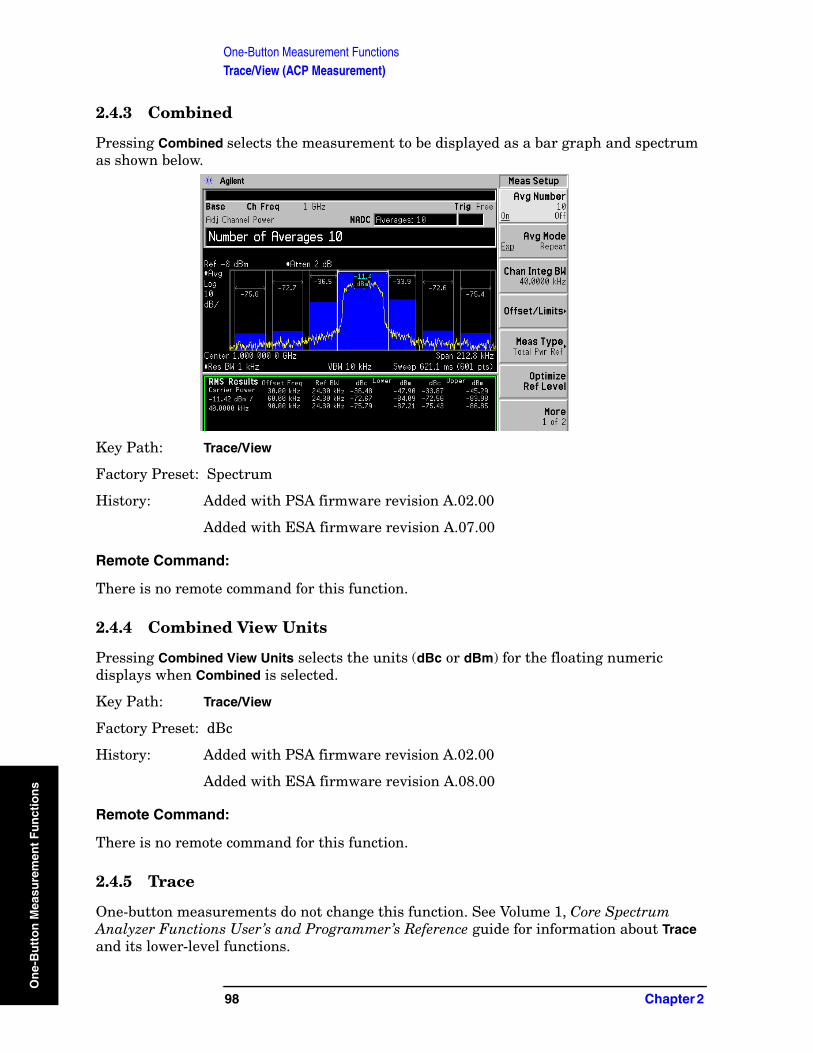
One-Button Measurement FunctionsTrace/View (ACP Measurement)
On
e-B
utt
on
Mea
sure
men
t F
un
ctio
ns
2.4.3 Combined
Pressing Combined selects the measurement to be displayed as a bar graph and spectrum as shown below.
Key Path: Trace/View
Factory Preset: Spectrum
History: Added with PSA firmware revision A.02.00
Added with ESA firmware revision A.07.00
Remote Command:
There is no remote command for this function.
2.4.4 Combined View Units
Pressing Combined View Units selects the units (dBc or dBm) for the floating numeric displays when Combined is selected.
Key Path: Trace/View
Factory Preset: dBc
History: Added with PSA firmware revision A.02.00
Added with ESA firmware revision A.08.00
Remote Command:
There is no remote command for this function.
2.4.5 Trace
One-button measurements do not change this function. See Volume 1, Core Spectrum Analyzer Functions User’s and Programmer’s Reference guide for information about Trace and its lower-level functions.
98 Chapter 2
One-Button Measurement FunctionsMeas Setup (Burst Power)
On
e-Bu
tton
Measu
remen
t Fu
nctio
2.5 Meas Setup (Burst Power)
When Burst Power has been selected in the Measure menu of the Spectrum Analysis Mode, this key displays the appropriate measurement setup menu.
The burst power measurement is an accurate method of determining the average power for the specified burst.
NOTE ESA Only: When selecting radio standards: NADC or PDC, the burst power measurement configures RF burst setup (Trig, More, RF Burst Setup) mode and level to accurately measure a signal with any combination of timeslots active. However, for signals with all timeslots active, set the parameters for RF burst setup as follows:
1. Select RF Burst Setup. (Trig, RF Burst Setup)
2. Set the trigger level mode to relative. (Trigger Level (Rel)
3. Set the narrow pulse discriminator to off. (Narrow Pulse Discriminator (Off)
4. Set the threshold level to −30 dB. (Meas Setup, Threshold Lvl, − 3, 0, dB)
Key Path: Front-panel key
History: Added with PSA firmware revision A.02.00
Added with ESA firmware revision A.07.00
Remote Command:
There is no equivalent remote command.
2.5.1 Avg Number
Press Avg Number (On) to specify the number of measurement averages used when calculating the measurement result. The average is displayed at the end of each sweep.
Key Path: Meas Setup
State Saved: Saved in instrument state.
Factory Preset: 10 averages / Off
Range: 1 to 1000
History: Added with PSA firmware revision A.02.00
Added with ESA firmware revision A.07.00
Chapter 2 99
ns
One-Button Measurement FunctionsMeas Setup (Burst Power)
On
e-B
utt
on
Mea
sure
men
t F
un
ctio
ns
Remote Command:
[:SENSe]:BPOWer:AVERage:COUNt <integer>
[:SENSe]:BPOWer:AVERage:COUNt?
[:SENSe]:BPOWer:AVERage[:STATe] OFF|ON|0|1
[:SENSe]:BPOWer:AVERage[:STATe]?
Example: BPOW:AVER:COUN 100
BPOW:AVER ON
2.5.2 Avg Mode
Press Avg Mode to select the type of termination control used for the averaging function to either Exp or Repeat. This determines the averaging action after the specified number of measurements (average count) is reached.
• EXP (Exponential Averaging mode)—When you set Avg Mode to Exp, each successive data acquisition after the average count is reached is exponentially weighted and combined with the existing average. Exponential averaging weights new data more than old data, which facilitates tracking of slow-changing signals. The average will be displayed at the end of each sweep.
• Repeat—When you set Avg Mode to Repeat, after reaching the average count, all previous result data is cleared and the average count is set back to 1.
Key Path: Meas Setup
State Saved: Saved in instrument state.
Factory Preset: EXPonential
Range: EXPonential|REPeat
History: Added with PSA firmware revision A.02.00.
Added with ESA firmware revision A.07.00
Remote Command:
[:SENSe]:BPOWer:AVERage:TCONrol EXPonential|REPeat
[:SENSe]:BPOWer:AVERage:TCONrol?
Example: BPOW:AVG:TCON EXPBPOW:AVG:TCON?
100 Chapter 2

One-Button Measurement FunctionsMeas Setup (Burst Power)
On
e-Bu
tton
Measu
remen
t Fu
nctio
2.5.3 Average Type
Allows you to specify the type of result averaging to be performed.
• Log — Selects averaging that sums the trace data and divides by the number of data points.
• RMS — Selects averaging that converts trace data from dB to power units, then averages the power trace data. This selection requires more time to perform.
Key Path: Meas Setup
Factory Preset: RMS
Range: RMS or Log
History: Added with PSA firmware revision A.02.00
Added with ESA firmware revision A.07.00
Remote Command:
[:SENSe]:BPOWer:AVERage:TYPe LPOWer|POWer
[:SENSe]:BPOWer:AVERage:TYPe?
Example: BPOW:AVG:TYP LPOWer to select Log type.BPOW:AVG:TYP?
2.5.4 Threshold Lvl
Enables you to set the level above which the mean carrier power calculation is based. The threshold level can be described in dB (Rel) or dBm (Abs).
Key Path: Meas Setup
Factory Preset: −30 dB
Terminators: dB or dBm
Default Terminator dB
Knob Increment: 0.1 dB/dBm
Step Key Increment: 6 dB/dBm
Range: –60 dBm to 60 dBm (in absolute mode)
–60 dB to 0 dB (in relative mode)
History: Added with PSA firmware revision A.02.00
Added with ESA firmware revision A.07.00
Chapter 2 101
ns

One-Button Measurement FunctionsMeas Setup (Burst Power)
On
e-B
utt
on
Mea
sure
men
t F
un
ctio
ns
Remote Command:
[:SENSe]:BPOWer:THReshold <number>
[:SENSe]:BPOWer:THReshold?
[:SENSe]:BPOWer:THReshold:TYPE ABSolute|RELative
[:SENSe]:BPOWer:THReshold:TYPE?
Example: SENS:BPOW:THR:TYPE ABS
2.5.5 Meas Method
Allows you to select the measurement method.
• Above Threshold Lvl — Selects the user defined threshold level or default level (–3.00 dB) as the criteria in making the measurement.
• Measured Burst Width — This measurement method is not available for the following radio standards: IS-95, J-STD-008, cdma2000-SR1, cdma2000-SR3, W-DCMA 3GPP.
NOTE The measurements described above are those available in SA mode (see MODE key). Other measurements are available in other modes if an optional personality is installed.
Key Path: Meas Setup
Factory Preset: Above Threshold Lvl (THReshold)
Range: Measured Burst Width (BWIDth) to Above Threshold Lvl (THReshold)
History: Added with PSA firmware revision A.02.00
Added with ESA firmware revision A.07.00
Remote Command:
[:SENSe]:BPOWer:METHod THReshold|BWIDth
[:SENSe]:BPOWer:METHod?
Example: BPOW:METH BWID to select burst width as the measurement method.
2.5.6 Burst Width
Sets the burst width parameter to automatic mode (Auto) or manual mode (Man).
• Auto — The burst width is automatically calculated based on the threshold level. For example, if the threshold level is set to 3 dB, the burst width will be the time between the two 3 dB points. This will update after each sweep, but before any results are calculated. Since the measurement only measures over the burst width, this will force a measurement between the 3 dB points.
102 Chapter 2
One-Button Measurement FunctionsMeas Setup (Burst Power)
On
e-Bu
tton
Measu
remen
t Fu
nctio
• Man — The burst width used for computing the burst power is controlled by either entering it directly or as a percentage of the measured burst width. In the percentage case, the burst width is computed just once based on the most recent measured burst width. In either case, the burst width is centered on the observed burst in each measurement.
NOTE This key will be unavailable (grayed out) if Meas Method is set to Above Threshold Lvl.
Key Path: Meas Setup
Factory Preset: 542.77 µs
Terminators: %, s, ms, µs, ns (% from front panel only)
Default Terminator: seconds (s)
Knob Increment: 0.1 µs
Step Key Increment: 10 µs
Range: 0.1 µs to 2 ks
History: Added with PSA firmware revision A.02.00
Added with ESA firmware revision A.07.00
Remote Command:
[:SENSe]:BPOWer:BURSt:WIDTh <time>
[:SENSe]:BPOWer:BURSt:WIDTh?
[:SENSe]:BPOWer:BURSt:AUTO OFF|ON|0|1
[:SENSe]:BPOWer:BURSt:AUTO?
Remote Command Notes: Burst width cannot be set remotely as a percent of the current burst width. That functionality is available from the front panel, but the command must be sent with a time value.
Example: SENS:BPOW:BURST:AUTO ON
Chapter 2 103
ns
One-Button Measurement FunctionsMeas Setup (Burst Power)
On
e-B
utt
on
Mea
sure
men
t F
un
ctio
ns
2.5.7 Optimize Ref Level
Sets the input attenuator and reference level to optimize the robustness of the measurement, which is its freedom from errors due to input compression and log amp range limitations.
NOTE There will always be a minimum of 2 dB for PSA or 5 dB for ESA of attenuation set to protect the analyzer input.
Key Path: Meas Setup
State Saved: Saved in instrument state.
Factory Preset: n/a
History: Added with PSA firmware revision A.02.00.
Added with ESA firmware revision A.07.00
Remote Command:
[:SENSe]:POWer[:RF]:RANGe:AUTO ONCE
Example: POW:RANG:AUTO ONCE
104 Chapter 2
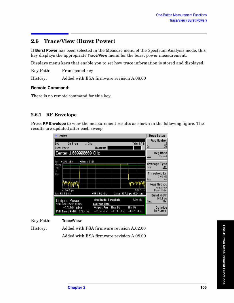
One-Button Measurement FunctionsTrace/View (Burst Power)
On
e-Bu
tton
Measu
remen
t Fu
nctio
2.6 Trace/View (Burst Power)
If Burst Power has been selected in the Measure menu of the Spectrum Analysis mode, this key displays the appropriate Trace/View menu for the burst power measurement.
Displays menu keys that enable you to set how trace information is stored and displayed.
Key Path: Front-panel key
History: Added with ESA firmware revision A.08.00
Remote Command:
There is no remote command for this key.
2.6.1 RF Envelope
Press RF Envelope to view the measurement results as shown in the following figure. The results are updated after each sweep.
Key Path: Trace/View
History: Added with PSA firmware revision A.02.00
Added with ESA firmware revision A.08.00
Chapter 2 105
ns
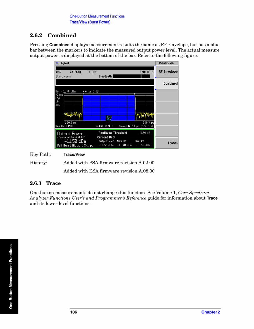
One-Button Measurement FunctionsTrace/View (Burst Power)
On
e-B
utt
on
Mea
sure
men
t F
un
ctio
ns
2.6.2 Combined
Pressing Combined displays measurement results the same as RF Envelope, but has a blue bar between the markers to indicate the measured output power level. The actual measure output power is displayed at the bottom of the bar. Refer to the following figure.
Key Path: Trace/View
History: Added with PSA firmware revision A.02.00
Added with ESA firmware revision A.08.00
2.6.3 Trace
One-button measurements do not change this function. See Volume 1, Core Spectrum Analyzer Functions User’s and Programmer’s Reference guide for information about Trace and its lower-level functions.
106 Chapter 2

One-Button Measurement FunctionsMeas Setup (Complementary Cumulative Distribution Function—CCDF)
On
e-Bu
tton
Measu
remen
t Fu
nctio
2.7 Meas Setup (Complementary Cumulative Distribution Function—CCDF)
When Power Stat CCDF has been selected in the Measure menu of the Spectrum Analysis mode, this key displays the appropriate measurement setup menu for the complementary cumulative distribution function (CCDF).
Power Complementary cumulative distribution function (CCDF) curves characterize the higher-level power of the signal. It provides the distribution of peak-to-average power ratios versus probability. A CCDF curve is defined by how much time the waveform spends at or above the specified power level. The percent of time the signal spends at or above this level defines the probability for that particular power level.
Key Path: Front-panel key
History: Added with PSA firmware revision A.02.00
Added with ESA firmware revision A.07.00.
Remote Command:
There is no equivalent remote command.
NOTE To make CCDF measurements on wide bandwidth signals up to 80 MHz, there is also a CCDF measurement in Basic mode if your instrument has Option 122 or 140.
2.7.1 Meas BW
Press Meas BW to set the measurement 3 dB bandwidth.
Key Path: Meas Setup
State Saved: Saved in instrument state.
Factory Preset: Defined by the radio standard selected.
Terminators: Hz, kHz, MHz, GHz
Knob Increment: Steps through available Res BW filters.
Step Key Increment: Steps through available Res BW filters.
Range: PSA Only: 10 kHz to 5 MHz
ESA Only: 10 kHz to 8 MHz
History: Added with PSA firmware revision A.02.00
Added with ESA firmware revision A.07.00.
Chapter 2 107
ns
One-Button Measurement FunctionsMeas Setup (Complementary Cumulative Distribution Function—CCDF)
On
e-B
utt
on
Mea
sure
men
t F
un
ctio
ns
Remote Command:
[:SENSe]:PSTatistic:BANDwidth|BWIDth <freq>
[:SENSe]:PSTatistic:BANDwidth|BWIDth?
Remote Command Notes: The entered value is rounded to the nearest Res BW filter frequency.
This command is coupled with the analyzer resolution bandwidth
Example: PST:BAND 10 or PST:BWID 10
PST:BAND? or PST:BWID?
2.7.2 Counts
Press Counts to set the accumulated number of sampling points for data acquisition. The range is 1 kpoints (kilopoint–1000 points) to 2.000000 Gpoints (Giga point–109 point) with 1 kpoint resolution. While this key is activated, enter a value from the numeric keypad by terminating with one of the unit keys shown.
Key Path: Meas Setup
State Saved: Saved in instrument state.
Factory Preset: 1.00e5
Range: 1e3 to 1e9
History: Added with PSA firmware revision A.02.00
Added with ESA firmware revision A.07.00.
Remote Command:
[:SENSe]:PSTatistic:COUNts <integer>
[:SENSe]:PSTatistic:COUNts?
Example: PST:COUN 1.0e6
PST:COUNt?
108 Chapter 2
One-Button Measurement FunctionsMeas Setup (Complementary Cumulative Distribution Function—CCDF)
On
e-Bu
tton
Measu
remen
t Fu
nctio
2.7.3 Meas Interval
Press Meas Interval to specify the time interval over which the measurement is made. The minimum setting is 100 µs. The maximum setting depends on the measurement bandwidth setting but never exceeds 600 ms. The resolution is 1 µs.
Key Path: Meas Setup
State Saved: Saved in instrument state.
Factory Preset: 1.0 ms
Default Terminator: s
Range: PSA Only: 100 µs to 600 ms
ESA Only: 1 µs minimum. Maximum value depends upon the measurement bandwidth. BW factor = 5 x meas BW or 10,000,000; whichever is less.
History: Added with PSA firmware revision A.02.00
Added with ESA firmware revision A.07.00.
Remote Command:
[:SENSe]:PSTatistic:SWEep:TIME <time>
[:SENSe]:PSTatistic:SWEep:TIME?
Example: PST:SWE:TIME 1.0e–3
PST:SWE:TIME?
Chapter 2 109
ns
One-Button Measurement FunctionsMeas Setup (Complementary Cumulative Distribution Function—CCDF)
On
e-B
utt
on
Mea
sure
men
t F
un
ctio
ns
2.7.4 Optimize Ref Level
PSA Only: Sets the input attenuator to optimize the robustness of the measurement, which is its freedom from errors due to input compression.
ESA Only: Sets the input attenuator and reference level to optimize the robustness of the measurement, which is its freedom from errors due to input compression and log amp range limitations.
NOTE There will always be a minimum of 2 dB for PSA or 5 dB for ESA of attenuation set to protect the analyzer input.
Key Path: Meas Setup
State Saved: Saved in instrument state.
History: Added with PSA firmware revision A.02.00
Added with ESA firmware revision A.07.00.
Remote Command:
[:SENSe]:POWer[:RF]:RANGe:AUTO ONCE
Example: POW:RANG:AUTO ONCE
110 Chapter 2
One-Button Measurement FunctionsDisplay (Complementary Cumulative Distribution Function—CCDF)
On
e-Bu
tton
Measu
remen
t Fu
nctio
2.8 Display (Complementary Cumulative Distribution Function—CCDF)Press Display to access menu keys that allow you to configure parameters for the CCDF measurement.
NOTE The keys described below are measurement dependent. To access the display menus, for the CCDF measurement press MEASURE, Power Stat CCDF, then Display.
2.8.1 Full Screen
Expands the measurement window horizontally over the entire instrument display. Pressing any other key that results in a new menu cancels the full screen function.
Any error occurring turns full screen mode off.
Key Path: Display
State Saved: Not saved in state.
Factory Preset: Off
Factory Default Off
History: Added with PSA firmware revision A.02.00
2.8.2 Store Ref Trace
Press Store Ref Trace to copy the currently measured curve as the user-definable reference trace. The captured data will remain until the other mode is chosen. Pressing this key refreshes the reference trace.
Remote Command:
:CALCulate:PSTatistic:STORe:REFerence
Example: CALC:PST:STOR:REF
2.8.3 Ref Trace
Press Ref Trace to toggle the reference trace display function between on and off.
Key Path: Display
State Saved: Saved in instrument state.
Factory Preset: Off
Chapter 2 111
ns

One-Button Measurement FunctionsDisplay (Complementary Cumulative Distribution Function—CCDF)
On
e-B
utt
on
Mea
sure
men
t F
un
ctio
ns
Remote Command:
:DISPlay:PSTatistic:RTRace[:STATe] OFF|ON|0|1
:DISPlay:PSTatistic:RTRace[:STATe]?
Example: DISP:PST:RTR 1
DISP:PST:RTR?
2.8.4 Gaussian Trace
Press Gaussian Trace to toggle the Gaussian trace display function between on and off.
Key Path: Display
State Saved: Saved in instrument state.
Factory Preset: On
Remote Command:
:DISPlay:PSTatistic:GAUSsian[:STATe] OFF|ON|0|1
:DISPlay:PSTatistic:GAUSsian[:STATe]?
Example: DISP:PST:GAUS 1
DISP:PST:GAUS?
2.8.5 Preferences
Displays the menu key that enables you to turn the graticule and annotation on or off.
Key Path: Display
State Saved: Saved in instrument state.
Factory Preset: No title
Fundamental Units: N/A
History: Added with PSA firmware revision A.02.00
2.8.5.1 Graticule
Pressing Graticule turns the display graticules on and off.
Key Path: Display, Preferences
Factory Preset: On
Factory Default: On
Terminators: Enter
History: Added with PSA firmware revision A.02.00
112 Chapter 2
One-Button Measurement FunctionsMarker (Complementary Cumulative Distribution Function—CCDF)
On
e-Bu
tton
Measu
remen
t Fu
nctio
2.9 Marker (Complementary Cumulative Distribution Function—CCDF) Displays the Marker control menu for the CCDF measurement. All markers are off until either Normal or Delta is pressed. There are three control modes for the markers:
• Normal (POSition) - A single marker placed at the 0 dB point of the selected value of Marker Trace that can be moved to any point on the trace.
• Delta (DELTa) - Places the selected marker and the next marker at the position of the previous marker on the specified trace (selected by pressing Marker Trace). The next marker is the reference marker (set to normal) and the selected marker is a moveable marker (delta) that you can place at any point on the trace. The difference between the selected marker and the reference marker is displayed.
• Off (Off) - Turns off the active marker.
Key Path: Front-panel key
State Saved: The control mode for each marker, as well as the position of each marker, is saved in instrument state.
Factory Preset: All Off.
History: Added with PSA firmware revision A.02.00
Added with ESA firmware revision A.07.00
Remote Command:
There is no equivalent remote command. These commands control the three marker modes. Refer to the Normal, Delta, and Off key descriptions for additional information.
:CALCulate:PSTatistic:MARKer[1]|2|3|4:MODE NORMal|DELTa|OFF
:CALCulate:PSTatistic:MARKer[1]|2|3|4:MODE?
Remote Command Notes: See also the marker positioning commands:
“Marker X Position (Remote Command Only)” on page 117
“Marker Y Position (Remote Command Only)” on page 118
“Marker Maximum and Minimum (Remote Command Only)” on page 118
Example: CALC:PST:MARK:MODE DELT activates a delta marker (marker 1) at the 0 dB point of your measurement (yellow line).
Chapter 2 113
ns
One-Button Measurement FunctionsMarker (Complementary Cumulative Distribution Function—CCDF)
On
e-B
utt
on
Mea
sure
men
t F
un
ctio
ns
2.9.1 Select Marker
Selects one of the four possible markers. Once a marker is selected, it can be set to any of the control modes Normal, Delta, or Off.
Key Path: Marker (after MEASURE, Power Stat CCDF is selected.)
State Saved: The number of the selected marker is saved in instrument state.
Factory Preset: Marker 1
History: Added with ESA firmware revision A.07.00
Remote Command:
:CALCulate:PSTatistic:MARKer[1]|2|3|4[:STATe] OFF|ON|0|1
:CALCulate:PSTatistic:MARKer[1]|2|3|4[:STATe]?
Sets or queries the state of a marker. Setting a marker to state ON or 1 selects that marker. Setting a marker which is OFF to state ON or 1 puts it in Normal mode and places it at the center of the display. Setting a marker to state OFF or 0 selects that marker and turns it off. The response to the query will be 0 if OFF, 1 if ON.
Example: CALC:PST:MARK2 ON selects marker 2.
CALC:PST:MARK:STAT ON will not modify a marker that is already on.
2.9.2 Normal
Sets the control mode for the selected marker to Normal. If the marker is off, a single marker is activated at the 0 dB point of the selected trace (see “Marker Trace” on page 116). You can then adjust the selected marker using the numeric keypad, knob, or ⇑ ⇓ keys.
Key Path: Marker (after MEASURE, Power Stat CCDF is selected.)
Factory Preset: Off
History: Added with ESA firmware revision A.07.00
Remote Command:
See Volume 1, Core Spectrum Analyzer Functions User’s and Programmer’s Reference guide.
Example: CALC:PST:MARK:MODE NORM selects marker 1 and sets it to Normal.
114 Chapter 2
One-Button Measurement FunctionsMarker (Complementary Cumulative Distribution Function—CCDF)
On
e-Bu
tton
Measu
remen
t Fu
nctio
2.9.3 Delta
Sets the control mode for the selected marker to Delta. In Delta mode the display shows the difference between the active (Delta) marker and a reference marker. When Delta mode is selected the reference marker is placed at the current marker position, unless the marker was OFF, in which case both the active marker and the reference marker are placed at 0 dB point of the selected trace (see “Marker Trace” on page 116). You can adjust the trace point of the active delta marker. Annotation in the active function block and in the upper-right corner of the display indicates the power ratio (dB) difference and probability (percentage) difference of the two markers.
Key Path: Marker (after MEASURE, Power Stat CCDF is selected.)
History: Added with ESA firmware revision A.07.00
Remote Command:
See Volume 1, Core Spectrum Analyzer Functions User’s and Programmer’s Reference guide.
Example: CALC:PST:MARK3:MODE DELT selects marker 3 as a delta marker and places a reference marker at the 0 dB point on the specified trace (see “Marker Trace” on page 116). If marker 3 is OFF it places both the active and the reference markers at the 0 dB point of the specified trace.
2.9.4 Off
Turns off the selected marker. In addition, Off also turns off functions related to the selected marker.
Key Path: Marker (after MEASURE, Power Stat CCDF is selected.)
History: Added with ESA firmware revision A.07.00
Remote Command:
See Volume 1, Core Spectrum Analyzer Functions User’s and Programmer’s Reference guide.
Example:
CALC:PST:MARK3:STAT OFF selects marker 3 and sets it to Off.
Chapter 2 115
ns
One-Button Measurement FunctionsMarker (Complementary Cumulative Distribution Function—CCDF)
On
e-B
utt
on
Mea
sure
men
t F
un
ctio
ns
2.9.5 Marker Trace
Chooses which trace the selected marker will be placed on. You can pick Measured, Gaussian, or Reference.
Key Path: Marker (after MEASURE, Power Stat CCDF is selected.)
State Saved: The Marker Trace for each marker is saved in instrument state.
Factory Preset: Measured
History: Added with ESA firmware revision A.07.00
Remote Command:
:CALCulate:PSTatistic:MARKer[1]|2|3|4:TRACe MEASured|GAUSsian|REFerence
Puts the marker on the specified trace.
:CALCulate:PSTatistic:MARKer[1]|2|3|4:TRACe?
The query returns the type of the trace on which the marker currently resides.
Example: CALC:PST:MARK1:TRAC GAUSsian places marker 1 on the Gaussian trace.
2.9.6 Marker All Off
Turns off all markers.
NOTE Selecting any measurement (including Meas Off) under Measure, turns off the marker table.
Key Path: Marker (after MEASURE, Power Stat CCDF is selected.)
History: Added with ESA firmware revision A.07.00
Remote Command:
:CALCulate:PSTatistic:MARKer[1]|2|3|4:AOFF
Example: CALC:PST:MARK:AOFF turns off all markers.
116 Chapter 2
One-Button Measurement FunctionsMarker (Complementary Cumulative Distribution Function—CCDF)
On
e-Bu
tton
Measu
remen
t Fu
nctio
2.9.7 Marker X Position (Remote Command Only)
Sets the marker X position (horizontal) to a specified point on the X axis in the current X-axis units (dB). If the value chosen would place the marker off screen, the marker will be placed at the left or right side of the display, on the specified trace (see “Marker Trace” on page 116). If the marker is off, this command has no effect.
Key Path: Marker
Key Notes: When a marker is active, you may use the knob, numeric keypad, or ⇑ ⇓ keys to specify the horizontal location of the marker.
Terminators: dB
Step Key Increment: 1 dB
Range: 0 to 50 dB
History: Added with PSA firmware revision A.02.00
Added with ESA firmware revision A.07.00
Remote Command:
:CALCulate:PSTatistic:MARKer[1]|2|3|4:X <dB>
Sets the marker X position in the current X-axis units (dB).
:CALCulate:PSTatistic:MARKer[1]|2|3|4:X?
Queries the marker X position in the current x-axis units. For the response to be valid, the marker must be on.
:CALCulate:PSTatistic:MARKer[1]|2|3|4:X:POSition <dB>
:CALCulate:PSTatistic:MARKer[1]|2|3|4:X:POSition?
This defines marker X position in display points from 0 to 50 dB.
Example: CALC:PST:MARK:X 30 dB activates a normal marker (marker 1) at the 30 dB location on the specified trace (see “Marker Trace” on page 116).
CALC:PST:MARK2:X:POS 10 selects marker 2 and moves it to 1 dB location on the specified trace.
Chapter 2 117
ns
One-Button Measurement FunctionsMarker (Complementary Cumulative Distribution Function—CCDF)
On
e-B
utt
on
Mea
sure
men
t F
un
ctio
ns
2.9.8 Marker Y Position (Remote Command Only)
Displays the marker Y position (vertical) of the specified trace (see “Marker Trace” on page 116) in the current Y-axis units (percent).
History: Added with PSA firmware revision A.02.00
Added with ESA firmware revision A.07.00
Remote Command:
:CALCulate:PSTatistic:MARKer[1]|2|3|4:Y?
Queries the marker Y value or delta in the current y axis units. The marker must be ON for the response to be valid.
Example: CALC:PST:MARK1:Y?
2.9.9 Marker Maximum and Minimum (Remote Command Only)
Moves the marker to the maximum or minimum detected amplitude value on the display. If the marker is off, this command has no effect.
History: Added with PSA firmware revision A.02.00
Added with ESA firmware revision A.07.00
Remote Command:
:CALCulate:PSTatistic:MARKer[1]|2|3|4:MAXimum
:CALCulate:PSTatistic:MARKer[1]|2|3|4:MINimum
Example: CALC:PST:MARK:MAX
CALC:PST:MARK3:MIN
118 Chapter 2
One-Button Measurement FunctionsSPAN X Scale (Complementary Cumulative Distribution Function—CCDF)
On
e-Bu
tton
Measu
remen
t Fu
nctio
2.10 SPAN X Scale (Complementary Cumulative Distribution Function—CCDF)
Activates the Span function for the CCDF measurement and displays the menu of span functions.
Key Path: Front-panel key
State Saved: Saved in Instrument State
Remote Command:
See the Scale/Div command below.
2.10.1 Scale/Div
Allows you to enter a numeric value to change the horizontal display sensitivity by setting the decibel units per horizontal graticule division.
Key Path: MEASURE, Power Stat CCDF, SPAN X Scale
State Saved: Saved in instrument state.
Factory Preset: 2.0 dB
Default Terminator: dB
Range: 0.1 to 20.00 dB with 0.01 dB resolution
Remote Command:
:DISPlay:PSTatistic:XSCale <rel_ampl>
:DISPlay:PSTatistic:XSCale?
Example DISP:PST:XSC 10 dB
DISP:PST:XSC?
Chapter 2 119
ns
One-Button Measurement FunctionsSPAN X Scale (Complementary Cumulative Distribution Function—CCDF)
On
e-B
utt
on
Mea
sure
men
t F
un
ctio
ns
120 Chapter 2

One-Button Measurement FunctionsMeas Setup (Channel Power—CHP)
On
e-Bu
tton
Measu
remen
t Fu
nctio
2.11 Meas Setup (Channel Power—CHP)
When the channel power measurement has been selected in the Measure menu of the Spectrum Analysis Mode, this key displays the appropriate measurement setup menu.
The Channel Power measurement measures the power and power spectral density in the channel bandwidth that you specify. One marker pair on the display indicates the edges of the channel bandwidth. The center frequency, reference level, and channel bandwidth must be set by the user.
Key Path: Front-panel key
Dependencies/Couplings: Menu changes depending on the Mode and Measurement selected.
State Saved: Not saved.
History: Added with PSA firmware revision A.02.00
Remote Command:
There is no equivalent remote command.
2.11.1 Avg Number
To specify the number of measurement averages used when calculating the measurement result set Avg Number to On. The average will be displayed at the end of each sweep. Setting Avg Number to Off disables measurement averaging.
Key Path: Meas Setup
State Saved: Saved in instrument state.
Factory Preset: 10 averages/ Off
Knob Increment: 1
Step Key Increment: 1
Range: 1 to 1000
Remote Command:
[:SENSe]:CHPower:AVERage:COUNt <integer>
[:SENSe]:CHPower:AVERage:COUNt?
[:SENSe]:CHPower:AVERage[:STATe] OFF|ON|0|1
[:SENSe]:CHPower:AVERage[:STATe]?
Chapter 2 121
ns

One-Button Measurement FunctionsMeas Setup (Channel Power—CHP)
On
e-B
utt
on
Mea
sure
men
t F
un
ctio
ns
Example: CHP:AVER:COUN 10
CHP:AVER:COUN?
CHP:AVER OFF
CHP:AVER?
2.11.2 Avg Mode
Press Avg Mode to select the type of termination control used for the averaging function to either Exp or Repeat. This determines the averaging action after the specified number of measurements (average count) is reached.
• EXP (Exponential Averaging mode)—When you set Avg Mode to Exp, each successive data acquisition after the average count is reached is exponentially weighted and combined with the existing average. Exponential averaging weights new data more than old data, which facilitates tracking of slow-changing signals. The average will be displayed at the end of each sweep.
• Repeat—When you set Avg Mode to Repeat, after reaching the average count, all previous result data is cleared and the average count is set back to 1.
Key Path: Meas Setup
State Saved: Saved in instrument state.
Factory Preset: EXPonential
Remote Command:
[:SENSe]:CHPower:AVERage:TCONrol EXPonential|REPeat
[:SENSe]:CHPower:AVERage:TCONrol?
Example: CHP:AVG:TCON EXP
CHP:AVG:TCON?
2.11.3 Integ BW
Press Integ BW to specify the range of integration used in calculating the power in the channel. The integration bandwidth is displayed on the trace as two markers connected by an arrow. Be sure the Span of the instrument is set between 1 and 10 times the integration bandwidth.
Key Path: Meas Setup
Key Notes: If RRC Filter is on, the actual integration bandwidth used is the displayed integration bandwidth multiplied by (1 + “Filter Alpha”).
State Saved: Saved in instrument state.
122 Chapter 2
One-Button Measurement FunctionsMeas Setup (Channel Power—CHP)
On
e-Bu
tton
Measu
remen
t Fu
nctio
Factory Preset: 2 MHz, or as defined by the selected radio standard.
Terminators: GHz, MHz, kHz, Hz
Default Terminator: Hz
Knob Increment: 1%
Step Key Increment: 1,1.5, 2, 3, 5, 7.5, 10...
Range: 100 Hz to maximum span supported by your analyzer.
Remote Command:
[:SENSe]:CHPower:BANDwidth|BWIDth:INTegration <freq>
[:SENSe]:CHPower:BANDwidth|BWIDth:INTegration?
Example: CHP:BAND:INT 1 MHz
CHP:BAND:INT?
2.11.4 Chan Pwr Span
Press Chan Pwr Span to set the analyzer span for the channel power measurement. When the RRC Filter is set to On, the lower limit for the span is .
Key Path: Meas Setup
State Saved: Saved in instrument state.
Factory Preset: 3 MHz, or as defined by the selected radio standard.
Default Terminator: Hz
Knob Increment: 1, 1.5, 2, 3, 5, 7.5, 10...
Step Key Increment: 1%
Range: Current integration bandwidth to 10 times the integration bandwidth or span of your analyzer.
Remote Command:
[:SENSe]:CHPower:FREQuency:SPAN <freq>
[:SENSe]:CHPower:FREQuency:SPAN?
Example: CHP:FREQ:SPAN 2 MHz
CHP:FREQ:SPAN?
1 alpha+( ) Integration BW×
Chapter 2 123
ns
One-Button Measurement FunctionsMeas Setup (Channel Power—CHP)
On
e-B
utt
on
Mea
sure
men
t F
un
ctio
ns
2.11.5 Optimize Ref Level
Sets the input attenuator and reference level to optimize the robustness of the measurement, which is its freedom from errors due to input compression and log amp range limitations.
NOTE There will always be a minimum of 2 dB for PSA or 5 dB for ESA of attenuation set to protect the analyzer input.
Key Path: Meas Setup
State Saved: Not saved.
Remote Command:
[:SENSe]:POWer[:RF]:RANGe:AUTO ONCE
Example: POW:RANG:AUTO ONCE
2.11.6 RRC Filter
Pressing RRC Filter turns the Root Raised Cosine filter on or off. This filter is the type specified in the TETRA and 3GPP W-CDMA standards. This parameter is only available when either 3GPP W-CDMA or TETRA has been selected as the Radio Std from the Mode Setup menu. If 3GPP W-CDMA is selected, the rolloff value (alpha) for the filter will be initially set to 0.22. T is set to 1/RefBW (default 260 ns). If TETRA is selected, the rolloff will be initially set to 0.35. T is set to 1/RefBW (default 55.56 µs). The rolloff value can be changed using Filter Alpha.
Key Path: Meas Setup
State Saved: Saved in instrument state.
Factory Preset: Off
History: Added with PSA firmware revision A.03.00.
Added with ESA firmware revision A.09.00.
Remote Command:
[:SENSe]:CHPower:FILTer[:RRC][:STATe] OFF|ON|0|1
[:SENSe]:CHPower:FILTer[:RRC][:STATe]?
Example: CHP:FILT 1
CHP:FILT?
124 Chapter 2
One-Button Measurement FunctionsMeas Setup (Channel Power—CHP)
On
e-Bu
tton
Measu
remen
t Fu
nctio
2.11.7 Filter Alpha
Press RRC Filter to input the alpha value for the RRC Filter. This parameter is only available when either 3GPP W-CDMA or TETRA has been selected as the Radio Std. from the Mode Setup menu.
Key Path: Meas Setup
State Saved: Saved in instrument state.
Factory Preset: 0.22 when W-CDMA is selected, 0.35 for TETRA, otherwise Off.
Knob Increment: 0.01
Step Key Increment: 0.1
Range: 0.01 to 1.0
History: Added with PSA firmware revision A.03.00.
Added with ESA firmware revision A.09.00.
Remote Command:
[:SENSe]:CHPower:FILTer[:RRC]:ALPHA <number>
[:SENSe]:CHPower:FILTer[:RRC]:ALPHA?
Example: CHP:FILT:ALPH 0.22
CHP:FILT:ALPH?
Chapter 2 125
ns
One-Button Measurement FunctionsMeas Setup (Channel Power—CHP)
On
e-B
utt
on
Mea
sure
men
t F
un
ctio
ns
126 Chapter 2
One-Button Measurement FunctionsMeas Setup (Harmonic Distortion)
On
e-Bu
tton
Measu
remen
t Fu
nctio
2.12 Meas Setup (Harmonic Distortion) When the harmonic distortion measurement has been selected in the Measure menu of the Spectrum Analysis Mode, this key displays the appropriate measurement setup menu.
Key Path: Front-Panel key
Dependencies/Couplings: This measurement is not available when external mixing has been
selected.
Saved State: Not saved.
2.12.1 Avg Number
Press Avg Number (On) to specify the number of measurement averages used when calculating the measurement result. The average will be displayed at the end of each sweep.
Key Path: Meas Setup
State Saved: Saved in instrument state.
Factory Preset: 10 averages / Off
Range: 1 to 1000
Remote Command:
[:SENSe]:HARMonics:AVERage:COUNt <integer>
[:SENSe]:HARMonics:AVERage:COUNt?
[:SENSe]:HARMonics:AVERage[:STATe] OFF|ON|0|1
[:SENSe]:HARMonics:AVERage[:STATe]?
Example: HARM:AVER:COUN 100
HARM:AVER ON
Chapter 2 127
ns
One-Button Measurement FunctionsMeas Setup (Harmonic Distortion)
On
e-B
utt
on
Mea
sure
men
t F
un
ctio
ns
2.12.2 Avg Mode
Press Avg Mode to select the type of termination control used for the averaging function to either Exp or Repeat. This determines the averaging action after the specified number of measurements (average count) is reached.
• EXP (Exponential Averaging mode)—When you set Avg Mode to Exp, each successive data acquisition after the average count is reached is exponentially weighted and combined with the existing average. Exponential averaging weights new data more than old data, which facilitates tracking of slow-changing signals. The average will be displayed at the end of each sweep.
• Repeat—When you set Avg Mode to Repeat, after reaching the average count, all previous result data is cleared and the average count is set back to 1.
Key Path: Meas Setup
State Saved: Saved in instrument state.
Factory Preset: EXPonential
Range: EXPonential|REPeat
History: Added with PSA firmware revision A.02.00.
Remote Command:
[:SENSe]:HARMonics:AVERage:TCONrol EXPonential|REPeat
[:SENSe]:HARMonics:AVERage:TCONrol?
Example: HARM:AVG:TCON EXP
HARM:AVG:TCON?
2.12.3 Harmonics
Harmonics indicates the number of harmonics to measure before computing the total harmonic distortion. The minimum number is 2 (only the fundamental and second harmonic will be measured). The maximum number is 10.
Key Path: Meas Setup
State Saved: Saved in instrument state.
Factory Preset: 10
Range: 2 to 10
Remote Command:
[:SENSe]:HARMonics:NUMBer <integer>
[:SENSe]:HARMonics:NUMBer?
Example: HARM:NUMB 5
128 Chapter 2
One-Button Measurement FunctionsMeas Setup (Harmonic Distortion)
On
e-Bu
tton
Measu
remen
t Fu
nctio
2.12.4 ST/Harmonic
Sets the sweep time used to measure each harmonic. The value is set to 200 divided by the resolution bandwidth, or 10 ms, whichever is greater when the measurement is started. This sweep time is used only for measuring harmonics. The analyzer sweep time before the measurement was started is used for finding the fundamental.
Key Path: Meas Setup
State Saved: Saved in instrument state.
Factory Preset: 10 ms / Auto
Default Terminator: seconds
Range: 10 ms to maximum sweep time of the analyzer
Remote Command:
[:SENSe]:HARMonics:SWEeptime:STATe OFF|ON|0|1
[:SENSe]:HARMonics:SWEeptime:STATe?
[:SENSe]:HARMonics:SWEeptime <time>
[:SENSe]:HARMonics:SWEeptime?
Remote Command Notes: ON is equal to automatic (Auto). OFF is equal to manual (Man).
Example: HARM:SWE:STAT OFF
HARM:SWE 100 ms
2.12.5 Range Table (On/Off)
Press Range Table to specify whether the range table is to be used or not. When Range Table is set to Off the harmonics are measured. When Range Table is set to On the first active range is considered to be the fundamental and the subsequent active ranges are used as the harmonics. At least two ranges must be active if Range Table is set to On.
Key Path: Meas Setup
Factory Preset: See Table 2-1 on page 131.
Range: Off|On
History: Added with PSA firmware revision A.03.00
Added with ESA firmware revision A.09.00
Remote Command:
[:SENSe]:HARMonics:RTABle:STATe OFF|ON|0|1
[:SENSe]:HARMonics:RTABle:STATe?
Example: HARM:RTAB:STAT OFF
Chapter 2 129
ns
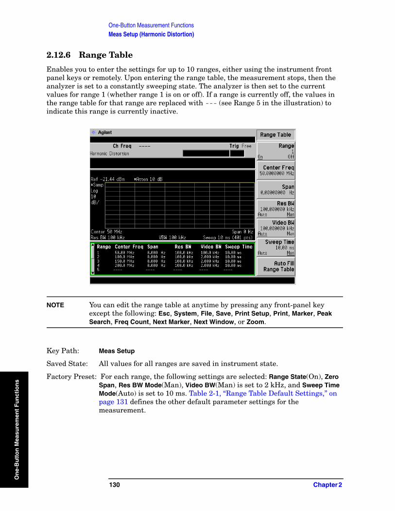
One-Button Measurement FunctionsMeas Setup (Harmonic Distortion)
On
e-B
utt
on
Mea
sure
men
t F
un
ctio
ns
2.12.6 Range Table
Enables you to enter the settings for up to 10 ranges, either using the instrument front panel keys or remotely. Upon entering the range table, the measurement stops, then the analyzer is set to a constantly sweeping state. The analyzer is then set to the current values for range 1 (whether range 1 is on or off). If a range is currently off, the values in the range table for that range are replaced with --- (see Range 5 in the illustration) to indicate this range is currently inactive.
NOTE You can edit the range table at anytime by pressing any front-panel key except the following: Esc, System, File, Save, Print Setup, Print, Marker, Peak Search, Freq Count, Next Marker, Next Window, or Zoom.
Key Path: Meas Setup
Saved State: All values for all ranges are saved in instrument state.
Factory Preset: For each range, the following settings are selected: Range State(On), Zero Span, Res BW Mode(Man), Video BW(Man) is set to 2 kHz, and Sweep Time Mode(Auto) is set to 10 ms. Table 2-1, “Range Table Default Settings,” on page 131 defines the other default parameter settings for the measurement.
130 Chapter 2
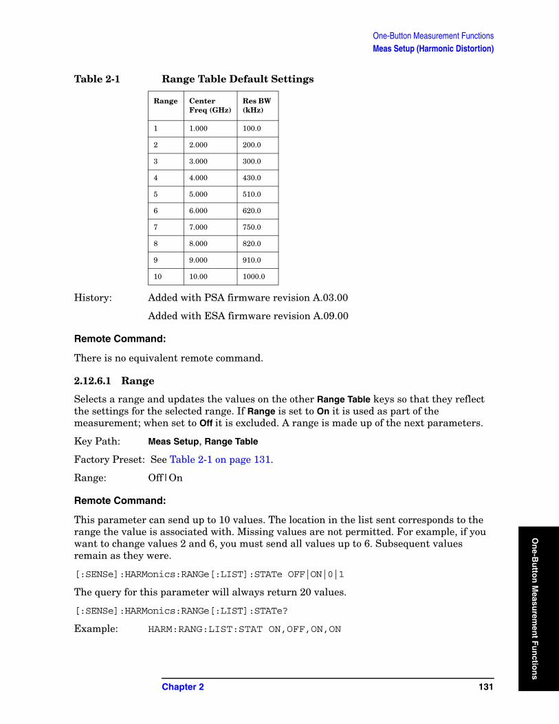
One-Button Measurement FunctionsMeas Setup (Harmonic Distortion)
On
e-Bu
tton
Measu
remen
t Fu
nctio
History: Added with PSA firmware revision A.03.00
Added with ESA firmware revision A.09.00
Remote Command:
There is no equivalent remote command.
2.12.6.1 Range
Selects a range and updates the values on the other Range Table keys so that they reflect the settings for the selected range. If Range is set to On it is used as part of the measurement; when set to Off it is excluded. A range is made up of the next parameters.
Key Path: Meas Setup, Range Table
Factory Preset: See Table 2-1 on page 131.
Range: Off|On
Remote Command:
This parameter can send up to 10 values. The location in the list sent corresponds to the range the value is associated with. Missing values are not permitted. For example, if you want to change values 2 and 6, you must send all values up to 6. Subsequent values remain as they were.
[:SENSe]:HARMonics:RANGe[:LIST]:STATe OFF|ON|0|1
The query for this parameter will always return 20 values.
[:SENSe]:HARMonics:RANGe[:LIST]:STATe?
Example: HARM:RANG:LIST:STAT ON,OFF,ON,ON
Table 2-1 Range Table Default Settings
Range CenterFreq (GHz)
Res BW (kHz)
1 1.000 100.0
2 2.000 200.0
3 3.000 300.0
4 4.000 430.0
5 5.000 510.0
6 6.000 620.0
7 7.000 750.0
8 8.000 820.0
9 9.000 910.0
10 10.00 1000.0
Chapter 2 131
ns
One-Button Measurement FunctionsMeas Setup (Harmonic Distortion)
On
e-B
utt
on
Mea
sure
men
t F
un
ctio
ns
2.12.6.2 Center Freq
Used to set the center frequency of the analyzer.
Key Path: Meas Setup, Range Table
Factory Preset: See Table 2-1 on page 131.
Knob Increment: 1%
Step Key Increment: 1, 1.5, 2, 3, 5, 7.5, 10,...
Range: Frequency range of your analyzer.
History: Added with PSA firmware revision A.03.00
Added with ESA firmware revision A.09.00
Remote Command:
This parameter can send up to 10 values. The location in the list sent corresponds to the range the value is associated. Missing values are not permitted, for example, if you want to change values 2 and 6, you must send all values up to 6. Subsequent values will remain as they were.
[:SENSe]:HARMonics:RANGe[:LIST]:FREQuency <integer>
The query for this parameter will always return 10 values.
[:SENSe]:HARMonics:RANGe[:LIST]:FREQuency?
Example: HARM:RANG:LIST FREQ 300
2.12.6.3 Span
Span is used to set the span of the analyzer.
Key Path: Meas Setup, Range Table
Factory Preset: See Table 2-1 on page 131.
Knob Increment: Steps through the available spans.
Step Key Increment: Steps through the available spans.
Range: Span of your analyzer.
History: Added with PSA firmware revision A.03.00
Added with ESA firmware revision A.09.00
132 Chapter 2
One-Button Measurement FunctionsMeas Setup (Harmonic Distortion)
On
e-Bu
tton
Measu
remen
t Fu
nctio
Remote Command:
This parameter can send up to 10 values. The location in the list sent corresponds to the range the value is associated with. Missing values are not permitted, for example, if you want to change values 2 and 6, you must send all values up to 6. Subsequent values will remain as they were.
[:SENSe]:HARMonics:RANGe[:LIST]:SPAN
[:SENSe]:HARMonics:RANGe[:LIST]:SPAN?
2.12.6.4 Res BW
Sets the resolution bandwidth mode of the analyzer. If the range is zero span and Res BW is set to Auto, the analyzer determines the optimum setting. Res BW set to Man enables you to determine the setting.
Key Path: Meas Setup, Range Table
Factory Preset: See Table 2-1.
Knob Increment: Steps through the available resolution bandwidth filters.
Step Key Increment: Steps through the available resolution bandwidth filters.
Range: Resolution bandwidth range of your analyzer.
History: Added with PSA firmware revision A.03.00
Added with ESA firmware revision A.09.00
Remote Command:
This parameter can send up to 10 values. The location in the list sent corresponds to the range the value is associated with. Missing values are not permitted, for example, if you want to change values 2 and 6, you must send all values up to 6. Subsequent values will remain as they were.
[:SENSe]:HARMonics:RANGe[:LIST]:BWIDth|BANDwidth[:RESolution]:AUTO OFF|ON|0|1 selects the mode.
[:SENSe]:HARMonics:RANGe[:LIST]:BWIDth|BANDwidth[:RESolution]<integer>
The query for this parameter always returns 10 values.
[:SENSe]:HARMonics:RANGe[:LIST]:BWIDth|BANDwidth[:RESolution]:AUTO?
[:SENSe]:HARMonics:RANGe[:LIST]:BWIDth|BANDwidth[:RESolution]?
Chapter 2 133
ns
One-Button Measurement FunctionsMeas Setup (Harmonic Distortion)
On
e-B
utt
on
Mea
sure
men
t F
un
ctio
ns
2.12.6.5 Video BW
Sets the video bandwidth of the analyzer. When Auto is selected the analyzer determines the optimum setting, while Man enables you to determine the setting.
Key Path: Meas Setup, Range Table
Factory Preset: Auto
Knob Increment: Steps through the available video bandwidth filters.
Step Key Increment: Steps through the available video bandwidth filters.
Range: Video bandwidth range of your analyzer.
History: Added with PSA firmware revision A.03.00
Added with ESA firmware revision A.09.00
Remote Command:
This parameter can send up to 10 values. The location in the list sent corresponds to the range the value is associated with. Missing values are not permitted, for example, if you want to change values 2 and 6, you must send all values up to 6. Subsequent values will remain as they were.
[:SENSe]:HARMonics:RANGe[:LIST]:BWIDth|BANDwidth:VIDeo:AUTO OFF|ON|0|1 selects the mode.
[:SENSe]:HARMonics:RANGe[:LIST]:BWIDth|BANDwidth:VIDeo <integer>
The query for this parameter will always return 10 values.
[:SENSe]:HARMonics:RANGe[:LIST]:BWIDth|BANDwidth:VIDeo:AUTO?
[:SENSe]:HARMonics:RANGe[:LIST]:BWIDth|BANDwidth:VIDeo?
2.12.6.6 Sweep Time
Sets the sweep time of the analyzer. If the range is zero span and Sweep Time is set to Auto, the sweep time will be 200 divided by the resolution bandwidth or 10 ms, whichever is greater. If the range is non zero span and Sweep Time is set to Auto, the analyzer determines the optimum setting. Sweep Time set to Man enables you to determine the setting.
Key Path: Meas Setup, Range Table
Factory Preset: Auto
Knob Increment: 1%
Step Key Increment: 1, 1.5, 2, 3, 5, 7.5, 10,...
Range: Sweep time range of your analyzer.
134 Chapter 2
One-Button Measurement FunctionsMeas Setup (Harmonic Distortion)
On
e-Bu
tton
Measu
remen
t Fu
nctio
History: Added with PSA firmware revision A.03.00
Added with ESA firmware revision A.09.00
Remote Command:
This parameter can send up to 10 values. The location in the list sent corresponds to the range the value is associated with. Missing values are not permitted, for example, if you want to change values 2 and 6, you must send all values up to 6. Subsequent values will remain as they were.
[:SENSe]:HARMonics:RANGe[:LIST]:SWEep:TIME:AUTO OFF|ON|0|1 selects the mode.
[:SENSe]:HARMonics:RANGe[:LIST]:SWEep:TIME: <integer>
The query for this parameter will always return 10 values.
[:SENSe]:HARMonics:RANGe[:LIST]:SWEep:TIME:AUTO?
[:SENSe]:HARMonics:RANGe[:LIST]:SWEep:TIME?
2.12.6.7 Auto Fill Range Table
Auto Fill Range Table is used to automatically setup the range table based on the current range center frequency and span. When selected, the current center frequency is taken as the fundamental and the frequency in range one is set to this value. Each of the subsequent range center frequency parameters are set to the appropriate integer multiple of the fundamental frequency. The span for range one is set to that of the current range. Each of the subsequent range span parameters are set to the appropriate integer multiple of the fundamental span. This means that if the fundamental range is zero span, all the ranges will be zero span. If the range span is zero, Res BW, Video BW, and Sweep Time are set to the current base instrument settings. If the range span is non-zero, Res BW, Video BW, and Sweep Time for all harmonics are set to the same settings as for the fundamental. Span is set to zero for all harmonics and the fundamental.
Key Path: Meas Setup, Range Table
Knob Increment: 1%
Step Key Increment: 1, 1.5, 2, 3, 5, 7.5, 10,...
Range: Sweep time range of your analyzer.
History: Added with PSA firmware revision A.03.00
Added with ESA firmware revision A.09.00
Remote Command:
[:SENSe]:HARMonics:RTABle:FILL <no query>
Example: HARM:RTAB:FILL
Chapter 2 135
ns
One-Button Measurement FunctionsMeas Setup (Harmonic Distortion)
On
e-B
utt
on
Mea
sure
men
t F
un
ctio
ns
2.12.7 Optimize Ref Level
Sets the input attenuator and reference level to optimize the robustness of the measurement, which is its freedom from errors due to input compression and log amp range limitations.
NOTE There will always be a minimum attenuation of 2 dB for PSA or 5 dB for ESA set to reduce the potential VSWR errors.
Key Path: Meas Setup
State Saved: Saved in instrument state.
History: Added with PSA firmware revision A.02.00.
Remote Command:
[:SENSe]:POWer[:RF]:RANGe:AUTO ONCE
Example: POW:RANG:AUTO ONCE
136 Chapter 2
One-Button Measurement FunctionsTrace/View (Channel Power Measurement)
On
e-Bu
tton
Measu
remen
t Fu
nctio
2.13 Trace/View (Channel Power Measurement)
If Channel Power has been selected in the Measure menu of the Spectrum Analysis mode, this key displays the appropriate Trace/View menu for the channel power measurement.
Displays menu keys that enable you to set how trace information is stored and displayed.
Key Path: Front-panel key
Factory Preset: Spectrum
History: Added with PSA firmware revision A.02.00
Remote Command:
There is no equivalent remote command for this function.
2.13.1 Spectrum
Pressing Spectrum selects the spectral display of the measurement.
Key Path: Trace/View
Factory Preset: Spectrum
History: Added with PSA firmware revision A.02.00
Remote Command:
There is no remote command for this function.
2.13.2 Combined
Pressing Combined selects the measurement to be displayed as a bar graph and spectrum.
Key Path: Trace/View
Factory Preset: Spectrum
History: Added with PSA firmware revision A.02.00
Remote Command:
There is no remote command for this function.
2.13.3 Trace
One-button measurements do not change this function. See Volume 1, Core Spectrum Analyzer Functions User’s and Programmer’s Reference guide for information about Trace and its lower-level functions.
Chapter 2 137
ns

One-Button Measurement FunctionsTrace/View (Channel Power Measurement)
On
e-B
utt
on
Mea
sure
men
t F
un
ctio
ns
138 Chapter 2
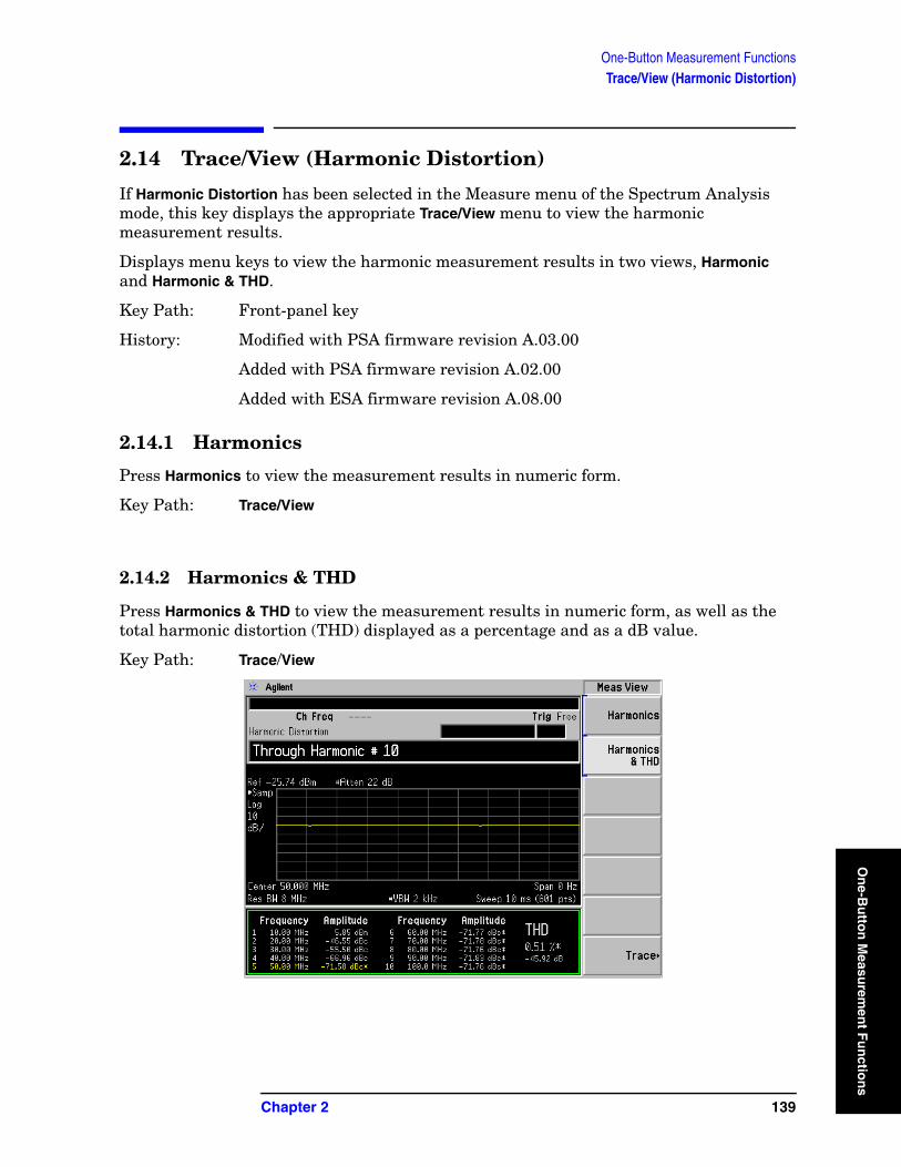
One-Button Measurement FunctionsTrace/View (Harmonic Distortion)
On
e-Bu
tton
Measu
remen
t Fu
nctio
2.14 Trace/View (Harmonic Distortion)
If Harmonic Distortion has been selected in the Measure menu of the Spectrum Analysis mode, this key displays the appropriate Trace/View menu to view the harmonic measurement results.
Displays menu keys to view the harmonic measurement results in two views, Harmonic and Harmonic & THD.
Key Path: Front-panel key
History: Modified with PSA firmware revision A.03.00
Added with PSA firmware revision A.02.00
Added with ESA firmware revision A.08.00
2.14.1 Harmonics
Press Harmonics to view the measurement results in numeric form.
Key Path: Trace/View
2.14.2 Harmonics & THD
Press Harmonics & THD to view the measurement results in numeric form, as well as the total harmonic distortion (THD) displayed as a percentage and as a dB value.
Key Path: Trace/View
Chapter 2 139
ns
One-Button Measurement FunctionsTrace/View (Harmonic Distortion)
On
e-B
utt
on
Mea
sure
men
t F
un
ctio
ns
140 Chapter 2
One-Button Measurement FunctionsMeas Setup (Intermod (TOI))
On
e-Bu
tton
Measu
remen
t Fu
nctio
2.15 Meas Setup (Intermod (TOI))
When Intermod (TOI) measurement has been selected in the Measure menu of the Spectrum Analysis Mode, this key displays the appropriate measurement setup menu for third order intercept (TOI).
The TOI measurement computes and displays the output intercept point (IP3), and places markers upon the trace to indicate the measured signals and third-order products. The span must be wide enough so that the signals and their intermod products are visible on the display. Otherwise the TOI signal pattern cannot be identified and the measurement routine will not function.
Key Path: Front-panel key
Dependencies/Couplings: Menu changes depending on the Mode and Measurement selected.
History: Added with PSA firmware revision A.02.00
Added with ESA firmware revision A.08.00
Remote Command:
There is no equivalent remote command.
2.15.1 Avg Number
Set Avg Number to On to specify the number of measurement averages used when calculating the measurement result. The average will be displayed at the end of each sweep. Setting Avg Number to Off disables measurement averaging.
Key Path: Meas setup
State Saved: Saved in instrument state.
Factory Preset: 10 averages / Off
Range: 1 through 1000
History: Added with PSA firmware revision A.02.00
Added with ESA firmware revision A.08.00
Remote Command:
[:SENSe]:TOIN:AVERage:COUNt <integer>
[:SENSe]:TOIN:AVERage:COUNt?
[:SENSe]:TOIN:AVERage[:STATe] OFF|ON|0|1
[:SENSe]:TOIN:AVERage[:STATe]?
Example: TOIN:AVER ON
TOIN:AVER?
Chapter 2 141
ns
One-Button Measurement FunctionsMeas Setup (Intermod (TOI))
On
e-B
utt
on
Mea
sure
men
t F
un
ctio
ns
2.15.2 Avg Mode
Press Avg Mode to select the type of termination control used for the averaging function to either Exp or Repeat. This determines the averaging action after the specified number of measurements (average count) is reached.
• EXP (Exponential Averaging mode)—When you set Avg Mode to Exp, each successive data acquisition after the average count is reached is exponentially weighted and combined with the existing average. Exponential averaging weights new data more than old data, which facilitates tracking of slow-changing signals. The average will be displayed at the end of each sweep.
• Repeat—When you set Avg Mode to Repeat, after reaching the average count, all previous result data is cleared and the average count is set back to 1.
Key Path: Meas Setup
State Saved: Saved in instrument state.
Factory Preset: EXPonential
History: Added with PSA firmware revision A.02.00
Added with ESA firmware revision A.08.00
Remote Command:
[:SENSe]:TOIN:AVERage:TCONrol EXPonential|REPeat
[:SENSe]:TOIN:AVERage:TCONrol?
Example: TOIN:AVG:TCON EXP
TOIN:AVG:TCON?
2.15.3 TOI Span
Press Span to specify the frequency span in which intermodulation products are measured.
Key Path: Meas Setup
Key Note: If you modify the value of Span in the base instrument Span menu, the value in the Meas Setup menu will be updated to reflect the new value and the measurement will restart if it is running.
Factory Preset: 15 MHz, or as defined by the radio standard selected.
Range: Non-Zero Span of Analyzer
History: Added with PSA firmware revision A.02.00
Added with ESA firmware revision A.08.00
142 Chapter 2
One-Button Measurement FunctionsMeas Setup (Intermod (TOI))
On
e-Bu
tton
Measu
remen
t Fu
nctio
Remote Command:
[:SENSe]:TOIN:FREQuency:SPAN <number>
[:SENSe]:TOIN:FREQuency:SPAN?
Example: TOIN:FREQ:SPAN 20 MHz
TOIN:FREQ:SPAN?
2.15.4 Max Mixer Lvl
Enables you to set the relationship between the highest signal that can be displayed (the reference level) and the input attenuation. The relationship applies whenever the Attenuation is set to Auto. The relationship is that the attenuation is given by reference level minus the max mixer level. For example, as the reference level changes, the input attenuator changes to ensure that a signal at the reference level does not exceed the Max Mixer Lvl setting.
When the TOI measurement is on, this key controls the maximum mixer level, independent of the previous setting of Max Mixer Lvl located under Amplitude. When the TOI measurement is Off, the previous maximum Max Mixer Lvl is restored.
Setting Max Mixer Lvl to Auto sets the maximum mixer level to −30 dBm.
Key Path: Meas Setup
Factory Preset: –30.00 dBm/Auto
Range: 0 VDC, +30 dBm
History: Added with PSA firmware revision A.02.00
Added with ESA firmware revision A.08.00
Remote Command:
[:SENSe]:TOIN:FREQuency:MIXer:RANGe[:UPPer] <number>
[:SENSe]:TOIN:FREQuency:MIXer:RANGe[:UPPer]?
[:SENSe]:TOIN:FREQuency:MIXer:RANGe:AUTO OFF|ON|0|1
[:SENSe]:TOIN:FREQuency:MIXer:RANGe:AUTO?
Example: TOIN:FREQ:MIX:RANG –10 dBm
TOIN:FREQ:MIX:RANG?
TOIN:FREQ:MIX:RANG:AUTO 1
TOIN:FREQ:MIX:RANG:AUTO?
Chapter 2 143
ns
One-Button Measurement FunctionsMeas Setup (Intermod (TOI))
On
e-B
utt
on
Mea
sure
men
t F
un
ctio
ns
2.15.5 Optimize Ref Level
Sets the reference level to place the tones near the top of the display. When input attenuation is set to Auto, pressing Optimize Ref Level sets the input attenuation according to the auto rules described in Max Mixer Lvl, based on this reference level. You may want to trade off analyzer noise and analyzer-induced distortion by manually changing the attenuation setting from this starting point.
NOTE There is always a minimum of 2 dB for PSA or 5 dB for ESA of attenuation set to protect the analyzer input.
Key Path: Meas Setup
State Saved: Saved in instrument state.
History: Added with PSA firmware revision A.02.00
Added with ESA firmware revision A.08.00
Remote Command:
[:SENSe]:POWer[:RF]:RANGe:AUTO ONCE
Example: TOIN:RANG:AUTO ONCE
TOIN:RANG:AUTO?
144 Chapter 2
One-Button Measurement FunctionsMeas Setup (Multi-Carrier Power—MCP)
On
e-Bu
tton
Measu
remen
t Fu
nctio
2.16 Meas Setup (Multi-Carrier Power—MCP)
If the MCP measurement has been selected in the Measure menu of the Spectrum Analysis mode, this key displays the MCP measurement setup menu.
The Multi-Carrier Power measurement is a measure of the power in two or more transmit channels and of the power that leaks into their adjacent transmit channels. The results reported are similar to the adjacent channel power measurement, but the setup is different to allow for two or more carriers to be present.
Key Path: Front-panel key
Dependencies/Couplings: • Parameter defaults change depending on the Radio Standard selected.
• Sweep time is coupled to span, RBW, and VBW if the measurement method is set to IBW.
• ESA Only: Video BW ≥ 10 times RBW (if possible)
History: Added with PSA firmware revision A.02.00
Added with ESA firmware revision A.08.00
Remote Command:
There is no equivalent remote command.
2.16.1 Avg Number
Pressing Avg Number to On enables you to specify the number of measurements that will be averaged when calculating the measurement result. The average will be displayed at the end of each sweep. Setting Avg Number to Off disables the measurement averaging.
Key Path: Meas Setup
State Saved: Saved in instrument state.
Factory Preset: 10 / Off
Range: 1 through 1000
History: Added with PSA firmware revision A.02.00
Added with ESA firmware revision A.08.00
Chapter 2 145
ns
One-Button Measurement FunctionsMeas Setup (Multi-Carrier Power—MCP)
On
e-B
utt
on
Mea
sure
men
t F
un
ctio
ns
Remote Commands:
[:SENSe]:MCPower:AVERage:COUNt <integer>
[:SENSe]:MCPower:AVERage:COUNt?
[:SENSe]:MCPower:AVERage[:STATe] OFF|ON|0|1
[:SENSe]:MCPower:AVERage[:STATe]?
Example: MCP:AVER:COUN 10
MCP:AVER:COUN?
MCP:AVER OFF
MCP:AVER?
2.16.2 Avg Mode
Press Avg Mode to select the type of termination control used for the averaging function as either Exp or Repeat. This determines the averaging action after the specified number of measurements (average count) is reached.
• EXP (Exponential Averaging mode)—When you set Avg Mode to Exp, each successive data acquisition after the average count is reached is exponentially weighted and combined with the existing average. Exponential averaging weights new data more than old data, which facilitates tracking of slow-changing signals. The average will be displayed at the end of each sweep.
• Repeat—When you set Avg Mode to Repeat, after reaching the average count, all previous result data is cleared and the average count is set back to 1.
Key Path: Meas Setup
State Saved: Saved in instrument state.
Factory Preset: Exponential
History: Added with PSA firmware revision A.02.00
Added with ESA firmware revision A.08.00
Remote Command:
[:SENSe]:MCPower:AVERage:TCONrol EXPonential|REPeat
[:SENSe]:MCPower:AVERage:TCONrol?
Example: MCP:AVG:TCON EXP
MCP:AVG:TCON?
146 Chapter 2

One-Button Measurement FunctionsMeas Setup (Multi-Carrier Power—MCP)
On
e-Bu
tton
Measu
remen
t Fu
nctio
2.16.3 Carrier Setup
Accesses the Carrier Setup and Configure Carriers menus that allow you to define the various parameters for each carrier.
Key Path: Meas Setup
History: Added with ESA firmware revision A.09.00.
Added with PSA firmware revision A.03.00.
Remote Command:
There is no equivalent remote command.
2.16.3.1 Carriers
Press Carriers to specify the number of carriers to be measured.
Key Path: Meas Setup, Carrier Setup
Factory Preset: 4
Step Key Increment: 1
Range: 2 to 12
History: Added with ESA firmware revision A.09.00.
Added with PSA firmware revision A.03.00.
Remote Command:
[:SENSe]:MCPower:CARRier:COUNt<integer>
[:SENSe]:MCPower:CARRier:COUNt?
Example: MCP:CARR:COUN 10
MCP:CARR:COUN?
2.16.3.2 Ref Carrier
Press Ref Carrier (Man) to specify the carrier (identified by a numeric position) from which all relative power measurements will be made. When Ref Carrier is set to Auto, the analyzer selects the carrier with the highest power as the reference.
Key Path: Meas Setup, Carrier Setup
Chapter 2 147
ns
One-Button Measurement FunctionsMeas Setup (Multi-Carrier Power—MCP)
On
e-B
utt
on
Mea
sure
men
t F
un
ctio
ns
Key Notes: The carrier must have power present in order to be assigned as a reference carrier frequency. If you change the reference carrier’s power present value from “yes” to “no”, the next carrier to the left (or to the right, if there are none to the left) will be assigned as the reference carrier. If it currently has power present set to No, this will change to Yes. This is also true when there are only two carriers with a “yes” value. Refer to the “Carrier Pwr Present” key description for more information on setting the carrier power present value.
Factory Preset: Auto
Range: Auto/Man1 to 12
History: Added with ESA firmware revision A.09.00.
Added with PSA firmware revision A.03.00.
Remote Command:
[:SENSe]:MCPower:RCARrier:AUTO OFF|ON|0|1
[:SENSe]:MCPower:RCARrier:AUTO?
[:SENSe]:MCPower:RCARrier<integer>
[:SENSe]:MCPower:RCARrier?
Remote Command Notes: Refer to “Key Notes:” above.
Example: MCP:RCAR:AUTO ON
MCP:RCAR 3
MCP:RCAR?
2.16.3.3 Ref Carrier Freq
The Ref Carrier Freq setting determines whether the Ref Carrier Freq is calculated based on the Center frequency (Auto) or the Center frequency is calculated based on the Ref Carrier Freq (Man). The Ref Carrier Freq value will always be updated if the Ref Carrier Freq setting is changed, whether the Mode is set to Auto or Man.
If Ref Carrier Freq is set to auto, it is assumed that the carriers are distributed evenly around the current center frequency. In this case the following three steps are used to calculate the Ref Carrier Freq value and the calculated Ref Carrier Freq is shown on the Ref Carrier Freq key:
1. Ref Freq 1 = Cntr Freq − [(Total of all Carrier Widths)/2]
2. Ref Freq 2 = Ref Freq 1+ (Total of all Carrier Widths excluding the Ref Carrier Width)
3. Ref Freq = Ref Freq 2 + [0.5 (Carrier Width of Ref Carrier)]
148 Chapter 2

One-Button Measurement FunctionsMeas Setup (Multi-Carrier Power—MCP)
On
e-Bu
tton
Measu
remen
t Fu
nctio
The Ref Carrier Freq can also be entered by the user. This will set the Ref Carrier Freq to Man and the Center frequency of the analyzer will be calculated using the following three steps:
1. Cntr Freq 1 = Ref Freq − [0.5 (Carrier Width of Ref Carrier)]
2. Cntr Freq 2 = Cntr Freq 1 − (Total of all Carrier Widths excluding the Ref Carrier Width)
3. Cntr Freq = Cntr Freq 2 + [(Total of all Carrier Widths)/2]
The above algorithms ensure that the carrier is centered on the analyzer display.
Key Path: Meas Setup, Carrier Setup
Dependencies/Couplings: The reference carrier can be re-assigned by implementing changes to
carrier power present values.
State Saved: Saved in instrument state.
Factory Preset: Auto/Calculated based on current center frequency. Refer to the algorithm above when defining the Ref Carrier Freq(Auto) key.
Terminators: Hz, kHz, MHz, GHz
Default Terminator GHz
Resolution: 1 Hz
Knob Increment: Span ÷ 50
Step Key Increment: If CF Step(Auto) is selected: span/10.
If CF Step(Man) is selected: CF Step
Range: Analyzer minimum to analyzer maximum
History Added with ESA firmware revision A.09.00.
Added with PSA firmware revision A.03.00.
Remote Command:
[:SENSe]:MCPower:RCFRequency<Freq>
[:SENSe]:MCPower:RCFRequency?
[:SENSe]:MCPower:RCFRequency:AUTO OFF|ON|0|1
[:SENSe]:MCPower:RCFRequency:AUTO?
Example: MCP:RCFR 2 GHz
MCP:RCFR?
Chapter 2 149
ns

One-Button Measurement FunctionsMeas Setup (Multi-Carrier Power—MCP)
On
e-B
utt
on
Mea
sure
men
t F
un
ctio
ns
2.16.3.4 Configure Carriers
Accesses the Config Carriers menu that allows further definition of each carrier.
Key Path: Meas Setup, Carrier Setup
History: Added with ESA firmware revision A.09.00.
Added with PSA firmware revision A.03.00.
Remote Command:
There is no equivalent remote command.
2.16.3.4.1 Carrier
Selects the carrier number you wish to configure.
Key Path: Meas Setup, Carrier Setup, Configure Carriers
Dependencies/Couplings: All keys available on the Configure Carrier menu are coupled to this key.
State Saved: Saved in instrument state.
Factory Preset: 1
Knob Increment: 1
Step Key Increment: 1
Range: 2 to 12
History: Added with ESA firmware revision A.09.00.
Added with PSA firmware revision A.03.00.
Remote Command:
There is no equivalent remote command.
2.16.3.4.2 Carrier Pwr Present
Press Carrier Pwr Present (Yes) to specify carriers which have power present. First, press the Carrier key and select the carrier number you wish to define, using the Step Keys (⇓ ⇑), the knob, or the numeric keypad. (The carrier number selected is shown on the Carrier key.) Then toggle the Carrier Pwr Present key to indicate either yes or no.
If a carrier is defined as having no power present, the power displayed will be relative to the reference carrier. If a carrier is defined as having power present, the absolute power will be displayed.
Carriers with power present are included in the total carrier power result.
Key Path: Meas Setup, Carrier Setup, Configure Carriers
150 Chapter 2
One-Button Measurement FunctionsMeas Setup (Multi-Carrier Power—MCP)
On
e-Bu
tton
Measu
remen
t Fu
nctio
Dependencies/Couplings: This key assigns a value (yes or no) to the carrier number displayed on the
Carrier key.
State Saved: Saved in instrument state.
Factory Preset: YES, YES, YES, YES
Range: Yes or No
History: Added with ESA firmware revision A.09.00.
Added with PSA firmware revision A.03.00.
Remote Command:
[:SENSe]:MCPower:CARRier:LIST:PPResent YES|NO
[:SENSe]:MCPower:CARRier:LIST:PPResent?
Remote Command Notes: • The position number in the list sent corresponds to the carrier number
you are designating. For example: “YES, YES, NO, YES, YES, NO” defines six carriers. Carriers 1, 2, 4, and 5 are defined as having power present whereas carriers 3 and 6 do not have power present. If you need to change carrier 5, you must send all carriers up to 5. Carrier 6 will remain unchanged. If you send more values than the number of carriers specified using the Carriers key, (in this example, there are six carriers) they will be ignored.
• The query for this parameter returns the current value for all carriers (with and without power present).
Example: MCP:CARR:PPR YES,NO,YES,NO,YES
MCP:CARR:PPR?
2.16.3.4.3 Carrier Width
Press Carrier Width to specify the width of each carrier including carriers with no power present. There is a corresponding one-to-one relationship between each carrier width value and the specified number of carriers. First, press the Carrier key and select the carrier number you wish to define, using the Step Keys (⇓ ⇑), the knob, or the numeric keypad. (The carrier number selected is shown on the Carrier key.) Then press the Carrier Width key and enter the width using the numeric keypad.
Key Path: Meas Setup, Carrier Setup, Configure Carriers
Key Notes: The Carrier key determines which carrier width you are defining.
State Saved: Saved in instrument state.
Factory Preset: 5 MHz, 5 MHz, 5 MHz, 5 MHz
Terminators: Hz, kHz, MHz, GHz
Chapter 2 151
ns
One-Button Measurement FunctionsMeas Setup (Multi-Carrier Power—MCP)
On
e-B
utt
on
Mea
sure
men
t F
un
ctio
ns
Default Terminator: Hz
Resolution: 1 Hz
Step Key Increment: If CF Step(Auto) is selected: span/10.
If CF Step(Man) is selected: CF Step
Range: 0 Hz to 500 MHz
History: Added with ESA firmware revision A.09.00.
Added with PSA firmware revision A.03.00.
Remote Command:
[:SENSe]:MCPower:CARRier:LIST:WIDTh <Hz>
[:SENSe]:MCPower:CARRier:LIST:WIDTh?
Remote Command Notes: • The position number of the each carrier width in the list sent
corresponds to the carrier number you are defining. For example: “5 MHz, 10 MHz, 5 MHz” defines six carriers. Carriers 1, 2, 4, and 5 are defined as having power present whereas carriers 3 and 6 do not have power present. If you need to change carrier 5, you must send all carriers up to 5. Carrier 6 will remain unchanged. If you send more values than the number of carriers specified using the Carriers key, (in this example, there are six carriers) they will be ignored.
• The query for this parameter returns the current value for all carriers (with and without power present).
Example: MCP:CARR:LIST:WIDT 5 MHz,10 MHz,4 MHz,15 MHz,5 MHz,10 MHz
MCP:CARR:LIST:WIDT?
2.16.3.4.4 Carrier IntegBW
Press Carrier IntegBW to define the integration bandwidth used to calculate the power in the carriers.
Key Path: Meas Setup, Carrier Setup, Configure Carriers
State Saved: Saved in instrument state.
SCPI Status Bits/OPC Dependencies: The integration bandwidth is specified differently depending on the
radio standard selected. If Mode Setup, Radio Std, 3GPP W-CDMA is selected and the RRC filter is on, the actual integration bandwidth used will be the displayed integration bandwidth multiplied by (1 + filter alpha).
Factory Preset: 3.84 MHz, 3.84 MHz, 3.84 MHz, 3.84 MHz
Terminators: Hz, kHz, MHz, GHz
Default Terminator Hz
152 Chapter 2

One-Button Measurement FunctionsMeas Setup (Multi-Carrier Power—MCP)
On
e-Bu
tton
Measu
remen
t Fu
nctio
Resolution:
Knob Increment: Span ÷ 50
Step Key Increment: If CF Step(Auto) is selected: span/10.
If CF Step(Man) is selected: CF Step
Range: 100 Hz to 500 MHz
History: Added with ESA firmware revision A.09.00.
Added with PSA firmware revision A.03.00.
Remote Command:
[:SENSe]:MCPower:CARRier:LIST:BANDwidth|BWIDth[:INTegration]<Hz>
[:SENSe]:MCPower:CARRier:LIST:BANDwidth|BWIDth[:INTegration]?
Example: MCP:CARR:LIST:BAND 3.5MHz,2.85MHz,3.84MHz
2.16.4 Offsets/Limits
Displays menu keys that enable you to configure the offsets and limits for the MCP measurement.
Key Path: Meas Setup
History: Added with ESA firmware revision A.02.00
Added with PSA firmware revision A.08.00
Remote Command:
There is no equivalent remote command.
2.16.4.1 Offset
Enables you to select the offset the menu keys will affect. Press Offset until the letter of the desired offset (A, B, or C) is underlined.
Key Path: Meas Setup, Offset/Limits
Factory Preset: A
History: Added with PSA firmware revision A.02.00
Added with ESA firmware revision A.08.00
Remote Command:
There is no equivalent remote command.
Chapter 2 153
ns
One-Button Measurement FunctionsMeas Setup (Multi-Carrier Power—MCP)
On
e-B
utt
on
Mea
sure
men
t F
un
ctio
ns
2.16.4.2 Offset Freq
Sets the frequency difference between the center of the uppermost carrier and the center of the upper element of the offset pair, as well as the frequency difference between the center of the lower element of the offset pair and the center of the lowermost carrier. If you set the frequency of any offset to 0 Hz, the offset is turned off and not included in the displayed results.
Key Path: Meas Setup, Offset/Limits
State Saved: Saved in instrument state.
Factory Preset: 5 MHz, 10 MHz, 15 MHz
Terminators: Hz, kHz, MHz, GHz
Default Terminator: Hz
Range: 0 MHz to 45 MHz
History: Added with PSA firmware revision A.02.00
Added with ESA firmware revision A.09.00
Remote Command:
[:SENSe]:MCPower:OFFSet:LIST:[FREQuency]<Hz>,<Hz>,<Hz>
[:SENSe]:MCPower:OFFSet:LIST:[FREQuency]?
Example: MCP:OFFS:LIST:5MHz,7.5MHz,15MHz
MCP:OFFS:LIST:?
2.16.4.3 Offset Integ BW
Sets the bandwidth over which the power is integrated for the selected offset (refer to “Offset” above).
Key Path: Meas Setup, Offset/Limits
Key Notes: If RRC Filter is set to On, the actual integration bandwidth used is the displayed integration bandwidth multiplied by (1 + Filter Alpha).
State Saved: Saved in instrument state.
Factory Preset: 3.84 MHz, 3.84 MHz, 3.84 MHz
Terminators: Hz, kHz, MHz, GHz
Default Terminator: Hz
Knob Increment: Span ÷ 50
Step Key Increment: If CF Step(Auto) is selected: span/10
If CF Step(Man) is selected: CF Step
154 Chapter 2
One-Button Measurement FunctionsMeas Setup (Multi-Carrier Power—MCP)
On
e-Bu
tton
Measu
remen
t Fu
nctio
Range: 100 Hz to 20 MHz
History: Added with PSA firmware revision A.03.00
Added with ESA firmware revision A.09.00
Remote Command:
[:SENSe]:MCPower:OFFSet:LIST:BANDwidth|BWIDth:[INTegration]<Hz>,<Hz>,<Hz>
[:SENSe]:MCPower:OFFSet:LIST:BANDwidth|BWIDth:[INTegration]<Hz>,<Hz>,<Hz>
Example: MCP:OFFS:LIST:BWIDth 5MHz,3MHz,5MHz
MCP:OFFS:LIST:BWID?
2.16.4.4 Upper Offset Limit
Sets the limit for the selected offset (refer to “Offset” above) to the right of the carriers.
Key Path: Meas Setup, Offset/Limits
State Saved: Saved in instrument state.
Factory Preset: 0 dB, 0 dB, 0 dB
Default Terminator: dB
Knob Increment: 1
Step Key Increment: 5
Range: –200 dB to 200 dB
History: Added with PSA firmware revision A.03.00
Added with ESA firmware revision A.08.00
Remote Command:
:CALCulate:MCPower:OFFSet:LIST:LIMit:POSitive[:UPPer]:DATA <dB>,<dB>,<dB>
:CALCulate:MCPower:OFFSet:LIST:LIMit:POSitive[:UPPer]:DATA?
Example: CALC:MCP:OFFS:LIST:LIM:POS:DATA −50dB,−55dB,−60dB
:CALC:MCP:OFFS:LIST:LIM:POS:DATA?
2.16.4.5 Lower Offset Limit
Sets the limit for the selected offset (refer to “Offset” above) to the left of the carriers.
Key Path: Meas Setup, Offset/Limits
State Saved: Saved in instrument state.
Factory Preset: 0 dB, 0 dB, 0 dB
Chapter 2 155
ns
One-Button Measurement FunctionsMeas Setup (Multi-Carrier Power—MCP)
On
e-B
utt
on
Mea
sure
men
t F
un
ctio
ns
Default Terminator: dB
Knob Increment: 1
Step Key Increment: 5
Range: –200 dB through 200 dB
History: Added with PSA firmware revision A.03.00
Added with ESA firmware revision A.08.00
Remote Command:
:CALCulate:MCPower:OFFSet:LIST:LIMit:NEGative[:UPPer]:DATA <dB>,<dB>,<dB>
:CALCulate:MCPower:OFFSet:LIST:LIMit:NEGative[:UPPer]:DATA?
Example: CALC:MCP:OFFS:LIST:LIM:NEG:DATA −50dB,−55dB,−60dB
CALC:MCP:OFFS:LIST:LIM:NEG:DATA?
2.16.5 Carrier Result
Press Carrier Result to select the result you wish to display on the last line of the carrier power results list except when:
• the carrier result number ≤ 4 (the first 4 carrier power results are displayed)
• the carrier result number ≥ 9 (the last 4 carrier power results are displayed)
Key Path: Meas Setup
Key Notes: This key is only available when Meas Control, Measure (Single) is selected.
State Saved: Not saved.
Factory Preset: 1
Step Key Increment: 1
Range: 1 to number of carriers.
History Added with PSA firmware revision A.03.00
Added with ESA firmware revision A.09.00
Remote Command:
There is no equivalent remote command.
2.16.6 Optimize Ref Level
PSA Only: Sets the input attenuator to optimize the robustness of the measurement, which is its freedom from errors due to input compression.
156 Chapter 2
One-Button Measurement FunctionsMeas Setup (Multi-Carrier Power—MCP)
On
e-Bu
tton
Measu
remen
t Fu
nctio
ESA Only: Sets the input attenuator and reference level to optimize the robustness of the measurement, which is its freedom from errors due to input compression and log amp range limitations.
NOTE There will always be a minimum of 2 dB for PSA or 5 dB for ESA of attenuation set to reduce the potential errors due to VSWR.
Key Path: Meas Setup
State Saved: Not saved.
History: Added with PSA firmware revision A.02.00
Added with ESA firmware revision A.08.00
Remote Command:
[:SENSe]:POWer[:RF]:RANGe:AUTO ONCE
Example: POW:RANG:AUTO ONCE
2.16.7 Method
Enables you to set the measurement method to either the integration bandwidth method (IBW) or the resolution bandwidth method (RBW). The resolution bandwidth method is most useful for measuring cdmaOne and cdma2000 signals. The integration bandwidth method is preferred for other signals.
Key Path: Meas Setup
Key Notes: When Method is set to RBW, neither Noise Correction nor RRC Filter are available.
State Saved: Saved in instrument state.
Factory Preset: IBW
Range: IBW|RBW
History: Added with PSA firmware revision A.02.00.
Added with ESA firmware revision A.09.00.
Remote Command:
[:SENSe]:MCPower:METHod IBW|RBW
[:SENSe]:MCPower:METHod?
Example: MCP:METH RBW
MCP:METH?
Chapter 2 157
ns
One-Button Measurement FunctionsMeas Setup (Multi-Carrier Power—MCP)
On
e-B
utt
on
Mea
sure
men
t F
un
ctio
ns
2.16.8 Power Ref
Enables you to set the multi-carrier power reference to automatic or manual. When set to automatic, the carrier power result reflects the measured power value in the selected reference carrier (Meas Setup, Carrier Setup, Ref Carrier). When set to manual, the result is referenced to the last measured value, or you may specify the reference for the multi-carrier power measurement. Relative values are displayed, referenced to the “Power Reference” value.
Key Path: Meas Setup
State Saved: Saved in instrument state.
Factory Preset: Off/Measured power in the reference carrier.
Terminators: dBm
Default Terminator: dBm
Range: –200 dBm to 200 dBm
History: Added with PSA firmware revision A.02.00.
Added with ESA firmware revision A.09.00.
Remote Command:
[:SENSe]:MCPower:CARRier:AUTO[:STATe] OFF|ON|0|1
[:SENSe]:MCPower:CARRier:AUTO[:STATe]?
[:SENSe]:MCPower:CARRier[:POWer]<dBm>
[:SENSe]:MCPower:CARRier[:POWer]?
Example: MCP:CARR:AUTO 0
MCP:CARR:AUTO?
MCP:CARR -100
MCP:CARR?
2.16.9 Limit Test
Pressing Limit Test turns the testing of the limit line on or off. When Limit Test is set to On, each offset is compared to its upper and lower offset limit. In those cases where the power exceeds the limit, a red “F” is placed next to the dBc result to indicate a failure. If there are any failures, the pass/fail indicator area show “FAIL” in red; if there are none, it shows “PASS” in green. Any offsets that are in the off state (see “Offset Freq” on page 154) are not measured and their results will not be displayed on screen.
Key Path: Meas Setup, More
State Saved: Saved in instrument state.
Factory Preset: Off
158 Chapter 2
One-Button Measurement FunctionsMeas Setup (Multi-Carrier Power—MCP)
On
e-Bu
tton
Measu
remen
t Fu
nctio
History: Added with PSA firmware revision A.02.00
Added with ESA firmware revision A.08.00
Remote Command:
[:SENSe]:MCPower:LIMit[:STATe] OFF|ON|0|1
[:SENSe]:MCPower:LIMit[:STATe]?
Example: MCP:LIM ON
MCP:LIM?
2.16.10 RRC Filter
Pressing RRC Filter turns the Root Raised Cosine filter on or off for the carriers and all adjacent channels. The RRC filter is the type specified in the 3GPP W-CDMA standards, with rolloff (α) = Filter Alpha parameter (defined below). T is set to 1/Carrier Integ BW (for carriers) or 1/Offset Integ BW (for Offsets).
Key Path: Meas Setup, More
Key Notes: This key is not available when Meas Setup, Method (RBW) is selected.
State Saved: Saved in instrument state.
Factory Preset: Off
History: Added with PSA firmware revision A.02.00
Added with ESA firmware revision A.09.00
Remote Command:
[:SENSe]:MCPower:FILTer[:RRC][:STATe] OFF|ON|0|1
[:SENSe]:MCPower:FILTer[:RRC][:STATe]?
Example: MCP:FILT 1
MCP:FILT?
2.16.11 Filter Alpha
Press Filter Alpha to input the alpha value for the RRC Filter. This parameter is only available when 3GPP W-CDMA has been selected as the radio standard from the Mode Setup menu.
Key Path: Meas Setup, More
State Saved: Saved in instrument state.
Factory Preset: 0.22 when W-CDMA is selected, otherwise Off.
Range: 0.01–1.00
Chapter 2 159
ns
One-Button Measurement FunctionsMeas Setup (Multi-Carrier Power—MCP)
On
e-B
utt
on
Mea
sure
men
t F
un
ctio
ns
History: Added with PSA firmware revision A.03.00.
Added with ESA firmware revision A.09.00.
Remote Command:
[:SENSe]:MCPower:FILTer[:RRC]:ALPHA <number>
[:SENSe]:MCPower:FILTer[:RRC]:ALPHA?
Example: MCP:FILT:ALPHA .33
MCP:FILT:ALPHA?
2.16.12 Noise Correction
Pressing Noise Correction turns noise correction on or off. When you set Noise Correction to On, a calibration of the noise floor is performed and used to correct for analyzer noise floor contribution to measurement levels, increasing dynamic range.
Key Path: Meas Setup, More
Key Notes: This key is not available when Meas Setup, Method (RBW) is selected or when signal tracking is on.
State Saved: Saved in instrument state.
Factory Preset: Off
History: Added with PSA firmware revision A.02.00.
Added with ESA firmware revision A.09.00.
Remote Command:
[:SENSe]:MCPower:CORRection:NOISe[:AUTO] OFF|ON|0|1
[:SENSe]:MCPower:CORRection:NOISe[:AUTO]?
Remote Command Notes: The noise correction feature is not available when the measurement method is RBW (Meas Setup, Method (RBW) or when signal tracking is on.
Example: MCP:CORR:NOIS 1
MCP:CORR:NOIS?
160 Chapter 2

One-Button Measurement FunctionsTrace/View (Multi-Carrier Power Measurement)
On
e-Bu
tton
Measu
remen
t Fu
nctio
2.17 Trace/View (Multi-Carrier Power Measurement)
If Multi-Carrier Power has been selected in the Measure menu of the Spectrum Analysis mode, this key displays the appropriate Trace/View menu for the multi-carrier power measurement.
Displays menu keys that enable you to set how trace information is stored and displayed.
Key Path: Front-panel key
History: Added with PSA firmware revision A.02.00
Added with ESA firmware revision A.08.00
Remote Command:
There is no equivalent remote command for this function.
2.17.1 Spectrum
Pressing Spectrum selects the spectral display of the measurement.
Key Path: Trace/View
Factory Preset: Spectrum
History: Added with PSA firmware revision A.02.00
Added with ESA firmware revision A.08.00
Remote Command:
There is no remote command for this function.
2.17.2 Combined
Pressing Combined selects the measurement to be displayed as a bar graph and spectrum.
Key Path: Trace/View
Factory Preset: Spectrum
History: Added with PSA firmware revision A.02.00
Added with ESA firmware revision A.08.00
Remote Command:
There is no remote command for this function.
Chapter 2 161
ns

One-Button Measurement FunctionsTrace/View (Multi-Carrier Power Measurement)
On
e-B
utt
on
Mea
sure
men
t F
un
ctio
ns
2.17.3 Combined View Units
Pressing Combined View Units selects the units (dBc or dBm) for the floating numeric displays when Combined is selected.
Key Path: Trace/View
Factory Preset: dBc
History: Added with PSA firmware revision A.02.00
Added with ESA firmware revision A.08.00
Remote Command:
There is no remote command for this function.
2.17.4 Trace
One-button measurements do not change this function. See Volume 1, Core Spectrum Analyzer Functions User’s and Programmer’s Reference guide for information about Trace and its lower-level functions.
162 Chapter 2
One-Button Measurement FunctionsMeas Setup (Occupied Bandwidth—OBW)
On
e-Bu
tton
Measu
remen
t Fu
nctio
2.18 Meas Setup (Occupied Bandwidth—OBW)
When Occupied BW has been selected in the Measure menu of the Spectrum Analysis Mode, this key displays the appropriate measurement setup menu.
The Occupied Bandwidth measurement integrates the power of the displayed spectrum and puts markers at the frequencies between which a selected percentage of the power is contained. The measurement defaults to 99% of the occupied bandwidth power. The power-bandwidth routine first computes the combined power of all signal responses contained in the trace. For 99% occupied power bandwidth, markers are placed at the frequencies on either side of 99% of the power and 1% of the power is evenly distributed outside the markers. The difference between the marker frequencies is the 99% power bandwidth and is the value displayed.
The occupied bandwidth function also indicates the difference between the analyzer center frequency and the center frequency of the channel, referred to as “Transmit Freq Error.” The measurement can be made in single or continuous sweep mode. The center frequency, reference level, and channel spacing must be set by the user.
Key Path: Front-panel key
2.18.1 Avg Number
Press Avg Number (On) to specify the number of measurement averages used when calculating the measurement result. The average is displayed at the end of each sweep. Press Avg Number (Off) to disable measurement averaging.
Key Path: Meas Setup
State Saved: Saved in instrument state.
Factory Preset: 10 averages / Off
Range: 1 through 1000
Remote Command:
[:SENSe]:OBWidth:AVERage:COUNt <integer>
[:SENSe]:OBWidth:AVERage:COUNt?
[:SENSe]:OBWidth:AVERage[:STATe] OFF|ON|0|1
[:SENSe]:OBWidth:AVERage[:STATe]?
Example: OBW:AVER:COUN 20
OBW:AVER:COUN?
OBW:AVER ON
OBW:AVER?
Chapter 2 163
ns
One-Button Measurement FunctionsMeas Setup (Occupied Bandwidth—OBW)
On
e-B
utt
on
Mea
sure
men
t F
un
ctio
ns
2.18.2 Avg Mode
Enables you to select the type of termination control used for the averaging function (Exp or Repeat). This determines the averaging action after the specified number of measurements (average count) is reached.
ESA Only: Avg Mode has no effect on measurements that are not averaged.
• EXP (Exponential Averaging mode)—Each successive data acquisition after the average count is reached is exponentially weighted and combined with the existing average. Exponential averaging weights new data more than old data, which facilitates tracking of slow-changing signals. The average is displayed at the end of each sweep.
• Repeat—After reaching the average count, all previous result data is cleared and the average count is set back to 1.
Key Path: Meas Setup
State Saved: Saved in instrument state.
Factory Preset: EXPonential
Remote Command:
[:SENSe]:OBW:AVERage:TCONtrol EXPonential|REPeat
[:SENSe]:OBW:AVERage:TCONtrol?
Example: OBW:AVG:TCON EXP
OBW:AVG:TCON?
2.18.3 Max Hold
Enables you to turn maximum hold trace feature on or off for the measurement. Maximum hold displays and holds the maximum responses of a signal.
Key Path: Meas Setup
State Saved: Saved in instrument state.
Factory Preset: Off
Remote Command:
[:SENSe]:OBW:MAXHold OFF|ON|0|1
[:SENSe]:OBW:MAXHold?
Example: OBW:MAXH ON
OBW:MAXH?
164 Chapter 2
One-Button Measurement FunctionsMeas Setup (Occupied Bandwidth—OBW)
On
e-Bu
tton
Measu
remen
t Fu
nctio
2.18.4 Occ BW % Pwr
Enables you to change the percentage of signal power used when determining the occupied bandwidth.
Key Path: Meas Setup
State Saved: Saved in instrument state.
Factory Preset: 99.0%
Range: 10.0% through 99.99%
Remote Command:
[:SENSe]:OBWidth:PERCent <percent>
[:SENSe]:OBWidth:PERCent?
Example: OBW:PERC 98
OBW:PERC?
2.18.5 OBW Span
Enables you to specify the range of integration used in calculating the total power from which the percent occupied bandwidth is then calculated. The analyzer span will be set to the same value as the OBW Span for the measurement. OBW Span should be set to approximately 2 times the expected occupied bandwidth result.
NOTE If you have an adjacent channel, you should not set the OBW span to 2 times your occupied bandwidth. The OBW measurement first computes all the power in the span and then 99% of that. Diamond markers are set around the bandwidth, and the occupied bandwidth results is displayed in the data window. If the power of the adjacent channel is included in the calculation for the 100% power, the OBW result will be too high. The OBW Span should be set narrow enough to encompass the channel of interest and exclude any unwanted adjacent channels.
Key Path: Meas Setup
Factory Preset: 3 MHz, or as defined by the radio standard selected.
Default Terminator: Hz
Range: 100 Hz to maximum span of the analyzer.
Remote Command:
[:SENSe]:OBW:FREQuency:SPAN <freq>
[:SENSe]:OBW:FREQuency:SPAN?
Chapter 2 165
ns
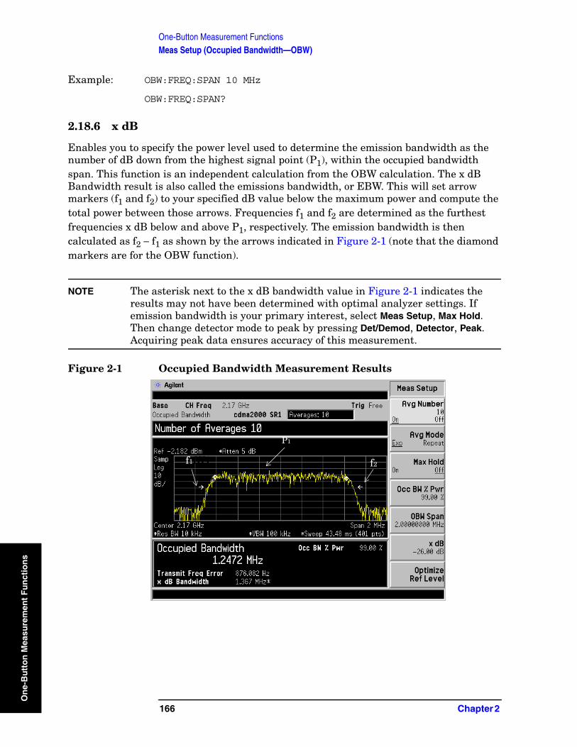
One-Button Measurement FunctionsMeas Setup (Occupied Bandwidth—OBW)
On
e-B
utt
on
Mea
sure
men
t F
un
ctio
ns
Example: OBW:FREQ:SPAN 10 MHz
OBW:FREQ:SPAN?
2.18.6 x dB
Enables you to specify the power level used to determine the emission bandwidth as the number of dB down from the highest signal point (P1), within the occupied bandwidth span. This function is an independent calculation from the OBW calculation. The x dB Bandwidth result is also called the emissions bandwidth, or EBW. This will set arrow markers (f1 and f2) to your specified dB value below the maximum power and compute the total power between those arrows. Frequencies f1 and f2 are determined as the furthest frequencies x dB below and above P1, respectively. The emission bandwidth is then calculated as f2 − f1 as shown by the arrows indicated in Figure 2-1 (note that the diamond markers are for the OBW function).
NOTE The asterisk next to the x dB bandwidth value in Figure 2-1 indicates the results may not have been determined with optimal analyzer settings. If emission bandwidth is your primary interest, select Meas Setup, Max Hold. Then change detector mode to peak by pressing Det/Demod, Detector, Peak. Acquiring peak data ensures accuracy of this measurement.
Figure 2-1 Occupied Bandwidth Measurement Results
P1
f1fff1 f2
166 Chapter 2
One-Button Measurement FunctionsMeas Setup (Occupied Bandwidth—OBW)
On
e-Bu
tton
Measu
remen
t Fu
nctio
ns
TIP ESA Only: This function looks similar to the N dB Points function found under the Peak Search front-panel key. However, the N dB Points arrows are referenced to the active marker, usually placed on a signal peak, and the frequency difference between the two arrows will be displayed in the upper right corner of the display. Whereas, the EBW indicated by the arrows x dB are referenced to the OBW power calculation integration of the power in the displayed spectrum.
Key Path: Meas Setup
State Saved: Saved in instrument state.
Factory Preset: –26 dB
Default Terminator: dB
Range: –100.0 dB through –0.1 dB
Remote Command:
[:SENSe]:OBW:XDB <dB value>
[:SENSe]:OBW:XDB?
Example: OBW:XDB —50 dB
OBW:XDB?
2.18.7 Optimize Ref Level
PSA Only: Sets the input attenuator to optimize the robustness of the measurement, which is its freedom from errors due to input compression.
ESA Only: Sets the input attenuator and reference level to optimize the robustness of the measurement, which is its freedom from errors due to input compression and log amp range limitations.
NOTE There will always be a minimum of 2 dB for PSA or 5 dB for ESA of attenuation set to protect the analyzer input.
Key Path: Meas Setup
State Saved: Saved in instrument state.
Factory Preset: n/a
Remote Command:
[:SENSe]:POWer[:RF]:RANGe:AUTO ONCE
Example: POW:RANG:AUTO ONCE
Chapter 2 167

One-Button Measurement FunctionsMeas Setup (Occupied Bandwidth—OBW)
On
e-B
utt
on
Mea
sure
men
t F
un
ctio
ns
168 Chapter 2
One-Button Measurement FunctionsMeas Setup (Spectrum Emissions Mask—SEM)
On
e-Bu
tton
Measu
remen
t Fu
nctio
2.19 Meas Setup (Spectrum Emissions Mask—SEM) When the spectrum emissions mask measurement has been selected in the Measure menu of the Spectrum Analysis Mode, this key displays the appropriate measurement setup menu.
Spectrum Emissions Mask (SEM) measurement includes the in-band and out-of-band spurious emissions. As it applies to W-CDMA (3GPP), this is the power contained in a specified frequency bandwidth at certain offsets relative to the total carrier power. It may also be expressed as a ratio of power spectral densities between the carrier and the specified offset frequency band.
Key Path: Front-panel key
History: Updated with PSA firmware revision A.08.00
Updated with PSA firmware revision A.03.00
Added with PSA firmware revision A.02.00
Updated with ESA firmware revision A.09.00
Added with ESA firmware revision A.08.00
2.19.1 Avg Number
Press Avg Number (On) to specify the number of measurement averages used when calculating the measurement result. The average will be displayed at the end of each sweep.
Key Path: Meas Setup
State Saved: Saved in instrument state.
Factory Preset: 10 averages / Off
Range: 1 through 1000
Remote Command:
[:SENSe]:SEMask:AVERage:COUNt <integer>
[:SENSe]:SEMask:AVERage:COUNt?
[:SENSe]:SEMask:AVERage[:STATe] OFF|ON|0|1
[:SENSe]:SEMask:AVERage[:STATe]?
Example: SEM:AVER:COUN 15
SEM:AVER 1
Chapter 2 169
ns

One-Button Measurement FunctionsMeas Setup (Spectrum Emissions Mask—SEM)
On
e-B
utt
on
Mea
sure
men
t F
un
ctio
ns
2.19.2 Meas Type
Displays a menu where you can select a measurement reference type, Total Pwr Ref or PSD Ref.
Key Path: Meas Setup
Factory Preset: Total Pwr Ref
Remote Command:
[:SENSE]:SEMask:TYPE TPRef|PSDRef
[:SENSE]:SEMask:TYPE?
Example: SEM:TYPE TPRef or SEM:TYPE PSDRef
SEM:TYPE?
2.19.2.1 Total Pwr Ref
When Total Pwr Ref is selected, the power in the carrier is used as the reference in computing the relative power values for the offsets.
Key Path: Meas Setup, Meas Type
History: Updated with PSA firmware revision A.03.00
Updated with ESA firmware revision A.09.00
2.19.2.2 PSD Ref
When PSD Ref is selected, the mean power spectral density of the carrier is used in computing the relative power spectral density values for the offsets.
Key Path: Meas Setup, Meas Type
Factory Preset: On (Auto)
History: Updated with PSA firmware revision A.03.00
Updated with ESA firmware revision A.09.00
2.19.3 Ref Channel
Accesses the menu of keys that enable you to change the reference channel settings.
Key Path: Meas Setup
170 Chapter 2
One-Button Measurement FunctionsMeas Setup (Spectrum Emissions Mask—SEM)
On
e-Bu
tton
Measu
remen
t Fu
nctio
2.19.3.1 Chan Integ BW
Specifies the integration bandwidth used in calculating the power in the main channel.
Key Path: Meas Setup, Ref Channel
Factory Preset: 3.84 MHz
Range: 10% to 100% of the setting of Chan Span
Remote Command:
[:SENSe]:SEMask:BANDwidth[n]|BWIDth[n]:INTegration <number>
[:SENSe]:SEMask:BANDwidth[n]|BWIDth[n]:INTegration?
Example: SEM:BAND[n]:INT 4 MHz
SEM:BWID[n]:INT 4 MHz
SEM:BAND[n]:INT?
SEM:BWID[n]:INT?
2.19.3.2 Chan Span
Specifies the span used in measuring the power in the main channel.
Key Path: Meas Setup, Ref Channel
Factory Preset: 5 MHz
Knob Increment: 1% of the set span.
Range: 1 kHz to 10 MHz
Remote Command:
[:SENSe]:SEMask:FREQuency:SPAN <number>
[:SENSe]:SEMask:FREQuency:SPAN?
Example: SEM:FREQ:SPAN 4 MHz
SEM:FREQ:SPAN?
2.19.3.3 Sweep Time
Specifies the sweep time used in measuring the power in the main channel.
Key Path: Meas Setup, Ref Channel
Factory Preset: Auto/On
Range: PSA:1 ms through 2 ks
ESA:1 ms through 4 ks
Chapter 2 171
ns
One-Button Measurement FunctionsMeas Setup (Spectrum Emissions Mask—SEM)
On
e-B
utt
on
Mea
sure
men
t F
un
ctio
ns
Remote Command:
[:SENSe]:SEMask:SWEeptime <number>
[:SENSe]:SEMask:SWEeptime?
[:SENSe]:SEMask:SWEeptime:AUTO OFF|ON|0|1
[:SENSe]:SEMask:SWEeptime:AUTO?
Example: SEM:SWE 4 sSEM:SWE?SEM:SWE:AUTO 1SEM:SWE:AUTO?
2.19.3.4 Res BW
Specifies the resolution bandwidth used in measuring and the power in the main channel.
Key Path: Meas Setup, Ref Channel
Factory Preset: PSA: 75 kHz
ESA: 30 kHz
Range: Full Range provided by Base Instrument Hardware.
History: Remote command updated with ESA firmware revision A.09.00
Remote command updated with PSA firmware revision A.03.00
Remote Command:
[:SENSe]:SEMask:BANDwidth|BWIDth[:RESolution] <freq>
[:SENSe]:SEMask:BANDwidth|BWIDth[:RESolution]?
[:SENSe]:SEMask:BANDwidth|BWIDth[:RESolution]:AUTO OFF|ON|0|1
[:SENSe]:SEMask:BANDwidth|BWIDth[:RESolution]:AUTO?
Remote Command Notes: See Volume 1, Core Spectrum Analyzer Functions User’s and Programmer’s Reference guide.
Example: SEM:BAND 4 MHzSEM:BWID 4 MHzSEM:BAND?SEM:BWID?
SEM:BAND:AUTO 1SEM:BWID:AUTO 1SEM:BAND:AUTO?SEM:BWID:AUTO?
172 Chapter 2
One-Button Measurement FunctionsMeas Setup (Spectrum Emissions Mask—SEM)
On
e-Bu
tton
Measu
remen
t Fu
nctio
2.19.3.5 Total Pwr Ref or PSD Ref
Displays the type of power measurement reference selected using the Meas Type key (see “Meas Type” on page 170).
Total Pwr Ref is the power in the carrier that is used as the reference in computing the relative power values for the offsets. When Man is selected, this can be set by the user. When Auto is selected, this is the measured power in the reference carrier.
PSD Ref is the mean power spectral density in the carrier that is used as the reference in computing the relative power spectral density values for the offsets. When Man is selected, this can be set by the user, when Auto is selected, this is the measured mean power spectral density in the reference carrier.
Key Path: Meas Setup, Ref Channel
Factory Preset: 0.00 dBm/Off
Range: –200.0 dBm to 200.0 dBm.
Remote Command:
[:SENSe]:SEMask:CARRier[:POWer] <ampl>
[:SENSe]:SEMask:CARRier[:POWer]?
[:SENSe]:SEMask:CARRier:AUTO[:STATe] OFF|ON|0|1
[:SENSe]:SEMask:CARRier:AUTO[:STATe]?
Example: SEM:CARR 0 dBm
SEM:CARR?
SEM:CARR:AUTO 1
SEM:CARR:AUTO?
2.19.4 Offset/Limits
Displays the menus where you can change the parameters for offset frequency settings and pass/fail tests. Refer to the tables below for default settings of particular radio standards of interest.
Chapter 2 173
ns
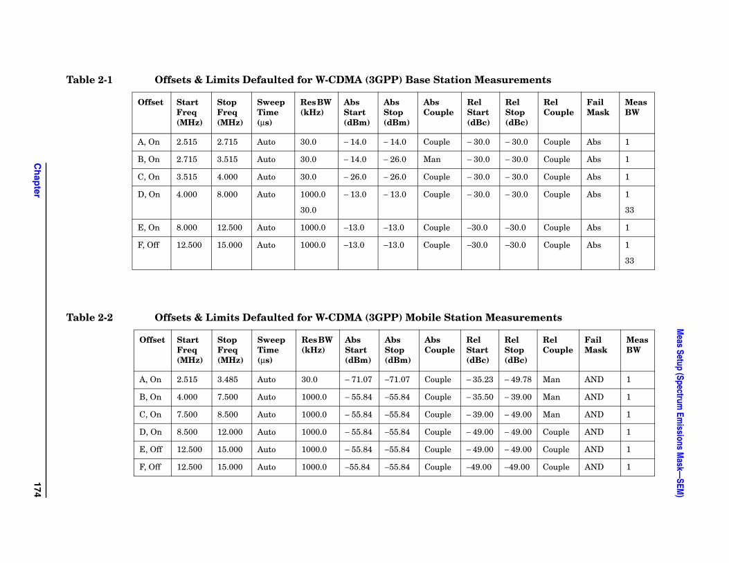
Ch
apter
174
Meas Setup (Spectrum
Emissions M
ask—SEM
)
rements
el top dBc)
Rel Couple
Fail Mask
Meas BW
30.0 Couple Abs 1
30.0 Couple Abs 1
30.0 Couple Abs 1
30.0 Couple Abs 1
33
30.0 Couple Abs 1
30.0 Couple Abs 1
33
surements
el top dBc)
Rel Couple
Fail Mask
Meas BW
49.78 Man AND 1
39.00 Man AND 1
49.00 Man AND 1
49.00 Couple AND 1
49.00 Couple AND 1
49.00 Couple AND 1
Table 2-1 Offsets & Limits Defaulted for W-CDMA (3GPP) Base Station Measu
Offset Start Freq (MHz)
Stop Freq (MHz)
Sweep Time (µs)
Res BW (kHz)
Abs Start (dBm)
Abs Stop (dBm)
Abs Couple
Rel Start (dBc)
RS(
A, On 2.515 2.715 Auto 30.0 − 14.0 − 14.0 Couple − 30.0 −
B, On 2.715 3.515 Auto 30.0 − 14.0 − 26.0 Man − 30.0 −
C, On 3.515 4.000 Auto 30.0 − 26.0 − 26.0 Couple − 30.0 −
D, On 4.000 8.000 Auto 1000.0
30.0
− 13.0 − 13.0 Couple − 30.0 −
E, On 8.000 12.500 Auto 1000.0 −13.0 −13.0 Couple −30.0 −
F, Off 12.500 15.000 Auto 1000.0 −13.0 −13.0 Couple −30.0 −
Table 2-2 Offsets & Limits Defaulted for W-CDMA (3GPP) Mobile Station Mea
Offset Start Freq (MHz)
Stop Freq (MHz)
Sweep Time (µs)
Res BW (kHz)
Abs Start (dBm)
Abs Stop (dBm)
Abs Couple
Rel Start (dBc)
RS(
A, On 2.515 3.485 Auto 30.0 − 71.07 −71.07 Couple − 35.23 −
B, On 4.000 7.500 Auto 1000.0 − 55.84 −55.84 Couple − 35.50 −
C, On 7.500 8.500 Auto 1000.0 − 55.84 −55.84 Couple − 39.00 −
D, On 8.500 12.000 Auto 1000.0 − 55.84 −55.84 Couple − 49.00 −
E, Off 12.500 15.000 Auto 1000.0 − 55.84 −55.84 Couple − 49.00 −
F, Off 12.500 15.000 Auto 1000.0 −55.84 −55.84 Couple −49.00 −
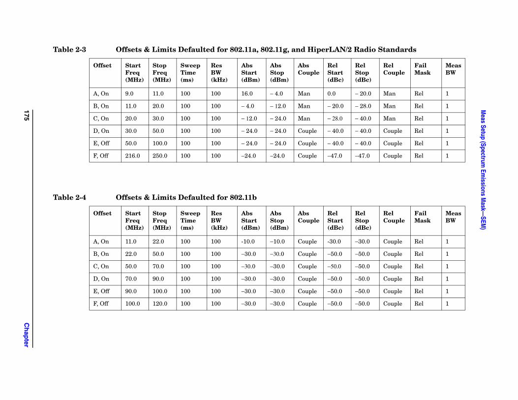
175C
hap
ter
Meas Setup (Spectrum
Emissions M
ask—SEM
)
Radio Standards
Rel Stop (dBc)
Rel Couple
Fail Mask
Meas BW
− 20.0 Man Rel 1
− 28.0 Man Rel 1
− 40.0 Man Rel 1
− 40.0 Couple Rel 1
− 40.0 Couple Rel 1
−47.0 Couple Rel 1
Rel Stop (dBc)
Rel Couple
Fail Mask
Meas BW
−30.0 Couple Rel 1
−50.0 Couple Rel 1
−50.0 Couple Rel 1
−50.0 Couple Rel 1
−50.0 Couple Rel 1
−50.0 Couple Rel 1
Table 2-3 Offsets & Limits Defaulted for 802.11a, 802.11g, and HiperLAN/2
Offset Start Freq (MHz)
Stop Freq (MHz)
Sweep Time (ms)
Res BW (kHz)
Abs Start (dBm)
Abs Stop (dBm)
Abs Couple
Rel Start (dBc)
A, On 9.0 11.0 100 100 16.0 − 4.0 Man 0.0
B, On 11.0 20.0 100 100 − 4.0 − 12.0 Man − 20.0
C, On 20.0 30.0 100 100 − 12.0 − 24.0 Man − 28.0
D, On 30.0 50.0 100 100 − 24.0 − 24.0 Couple − 40.0
E, Off 50.0 100.0 100 100 − 24.0 − 24.0 Couple − 40.0
F, Off 216.0 250.0 100 100 −24.0 −24.0 Couple −47.0
Table 2-4 Offsets & Limits Defaulted for 802.11b
Offset Start Freq (MHz)
Stop Freq (MHz)
Sweep Time (ms)
Res BW (kHz)
Abs Start (dBm)
Abs Stop (dBm)
Abs Couple
Rel Start (dBc)
A, On 11.0 22.0 100 100 -10.0 −10.0 Couple -30.0
B, On 22.0 50.0 100 100 −30.0 −30.0 Couple −50.0
C, On 50.0 70.0 100 100 −30.0 −30.0 Couple −50.0
D, On 70.0 90.0 100 100 −30.0 −30.0 Couple −50.0
E, Off 90.0 100.0 100 100 −30.0 −30.0 Couple −50.0
F, Off 100.0 120.0 100 100 −30.0 −30.0 Couple −50.0
One-Button Measurement FunctionsMeas Setup (Spectrum Emissions Mask—SEM)
On
e-B
utt
on
Mea
sure
men
t F
un
ctio
ns
2.19.4.1 Offset
Selects the offset pairs (upper and lower) that the menu keys affect, and displays the memory selection menu from A to E for ESA, or A to F for PSA (where you can store up to 6 sets of values for Start Freq, Stop Freq, Sweep Time, Res BW, Meas BW, Abs Start, Abs Stop, and so forth). Press Offset until the letter of the desired offset (A, B, C, D, E, or F) is underlined. Only one selection at a time is shown on this key label.
For PSA only: Since the display can show only five results at one time, the Results Index key allows you to scroll to the sixth result when all offsets are active.
Key Path: Meas Setup, Offset/Limits
State Saved: Saved in instrument state.
Factory Preset: A
Remote Command:
There is no remote command for this function.
2.19.4.2 Start Freq
Specifies the inner limit (frequency closest to the carrier) for both segments of the specified offset pair. When Start Freq (Off) is selected, the offset pair is not measured.
Key Path: Meas Setup, Offset/Limits
State Saved: Saved in instrument state.
Factory Preset: Dependent upon Radio Standard and device selected, refer to the default tables for “Offset/Limits” on page 173 for this value.
Default Terminator: Hz
Range: 0 Hz to 500 MHz
Remote Command:
[:SENSe]:SEMask:OFFSet[n]:LIST:FREQuency:STARt <freq>,... [<freq>](up to five values)
[:SENSe]:SEMask:OFFSet[n]:LIST:FREQuency:STARt?
[:SENSe]:SEMask:OFFSet[n]:LIST:STATe OFF|ON|0|
[:SENSe]:SEMask:OFFSet[n]:LIST:STATe?
Remote Command Notes: Comma separated list. When offset F is off, this will be 5 values. When offset F is on, this will be 6 values. n = 1 for BTS and n = 2 for MS. Default is BTS.
Offsets that are turned off, for the currently selected offset will return a -999.0 when queried.
176 Chapter 2
One-Button Measurement FunctionsMeas Setup (Spectrum Emissions Mask—SEM)
On
e-Bu
tton
Measu
remen
t Fu
nctio
Example: SEM:OFFS:LIST:FREQ:STAR 2 MHz
SEM:OFFS:LIST:FREQ:STAR?
SEM:OFFS:LIST:STAT 1
SEM:OFFS:LIST:STAT?
2.19.4.3 Stop Freq
Specifies the outer limit (frequency furthest from the carrier) for both segments of the specified offset pair. The lower range is limited to the setting of Start Freq.
Key Path: Meas Setup, Offset/Limits
State Saved: Saved in instrument state.
Factory Preset: Dependent upon Radio Standard and device selected, refer to the default tables for “Offset/Limits” on page 173 for this value.
Default Terminator: Hz
Range: 0 Hz to 500 MHz
Remote Command:
[:SENSe]:SEMask:OFFSet[n]:LIST:FREQuency:STOP <freq>... [<freq>](up to five values)
[:SENSe]:SEMask:OFFSet[n]:LIST:FREQuency:STOP?
Remote Command Notes: Comma separated list. When offset F is off, this will be 5 values. When offset F is on, this will be 6 values. n = 1 for BTS and n = 2 for MS. Default is BTS.
Example: SEM:OFFS:LIST:FREQ:STOP 4 MHz
SEM:OFFS:LIST:FREQ:STOP?
2.19.4.4 Sweep Time
Specifies the sweep time for the currently selected offset, and toggles this function between Auto and Manual for each offset.
Key Path: Meas Setup, Offset/Limits
State Saved: Saved in instrument state.
Factory Preset: Dependent upon Radio Standard and device selected, refer to the default tables for “Offset/Limits” on page 173 for this value.
Default Terminator: s (seconds)
Range: 1 ms to 42 ks
Chapter 2 177
ns
One-Button Measurement FunctionsMeas Setup (Spectrum Emissions Mask—SEM)
On
e-B
utt
on
Mea
sure
men
t F
un
ctio
ns
Remote Command:
[:SENSe]:SEMask:OFFSet[n]:LIST:SWEeptime <time>... [<time>] (up to five values)
[:SENSe]:SEMask:OFFSet[n]:LIST:SWEeptime?
[:SENSe]:SEMask:OFFSet[n]:LIST:SWEeptime:AUTO OFF|ON|0|1
[:SENSe]:SEMask:OFFSet[n]:LIST:SWEeptime:AUTO?
Remote Command Notes: Comma separated list. When offset F is off, this will be 5 values. When offset F is on, this will be 6 values. n = 1 for BTS and n = 2 for MS. Default is BTS.
Example: SEM:OFFS:LIST:SWE:AUTO 4 ms
SEM:OFFS:LIST:SWE:AUTO?
SEM:OFFS:LIST:SWE 4 ms
SEM:OFFS:LIST:SWE?
2.19.4.5 Res BW
Specifies the resolution bandwidth used in measuring the offset pair. When set to Auto, the Res BW from the default tables for “Offset/Limits” on page 173 are used. When set to Man, the range of settings is the range of available Res BWs of the analyzer, except the maximum is further limited to not exceed (Stop Freq - Start Freq).
Key Path: Meas Setup, Offset/Limits
State Saved: Saved in instrument state.
Factory Preset: Dependent upon Radio Standard and device selected, refer to the default tables for “Offset/Limits” on page 173 for this value.
Default Terminator: Hz
Remote Command:
[:SENSe]:SEMask:OFFSet[n]:LIST:BANDwidth|BWIDth[:RESolution] <freq>...[<freq>] (up to five values)
[:SENSe]:SEMask:OFFSet[n]:LIST:BANDwidth|BWIDth[:RESolution]?
[:SENSe]:SEMask:OFFSet[n]:LIST:BANDwidth|BWIDth[:RESolution]:AUTO OFF|ON|0|1
[:SENSe]:SEMask:OFFSet[n]:LIST:BANDwidth|BWIDth[:RESolution]:AUTO?
178 Chapter 2
One-Button Measurement FunctionsMeas Setup (Spectrum Emissions Mask—SEM)
On
e-Bu
tton
Measu
remen
t Fu
nctio
Remote Command Notes: Comma separated list. When offset F is off, this will be 5 values. When offset F is on, this will be 6 values. n = 1 for BTS and n = 2 for MS. Default is BTS.
You may only enter valid Res BW filter frequencies.
See Volume 1, Core Spectrum Analyzer Functions User’s and Programmer’s Reference guide.
Example: SEM:OFFS:LIST:BAND 40 kHz or SEM:OFFS:LIST:BWID 40 kHz
SEM:OFFS:LIST:BAND? or SEM:OFFS:LIST:BWID?
SEM:OFFS:LIST:BAND:AUTO 0 or SEM:OFFS:LIST:BWID:AUTO 0
SEM:OFFS:LIST:BAND:AUTO? or SEM:OFFS:LIST:BWID:AUTO?
2.19.4.6 Meas BW
Enables you to specify the bandwidth to use when measuring the offset. When using the front panel, only the currently selected offset is affected. All the offsets are affected when using the remote command. This is the multiplier applied to the resolution bandwidth to determine the bandwidth to integrate when calculating the power.
Key Path: Meas Setup, Offset/Limits
Key Notes: The 3GPP standard allows for the construction of an effective measurement bandwidth out of a group of narrower resolution bandwidths. This allowance is a remedy for the potential loss in dynamic range which can occur when carrier energy leaks into the offset due to the RBW filter’s shape factor (nominally 12:1). When the offset’s ratio of start frequency to the Meas BW is small (approximately 4:1), it is recommended that you select a small Res BW value (30 kHz) and a large multiplier (Meas BW=33) in order to increase the dynamic range of the measurement. Refer to offset D in Table 2-1 on page 174.
When setting Meas BW > 1, dynamic range is increased, however measurement time is also increased since an increased number of sweep points are required to make the measurement. For Meas BW > 1, consider this equation for trace points:
Trace points = (Offset Stop Freq - Offset Start Freq)/ (Meas BW/100)
When Meas BW = 1, the number of trace points are set at the value specified upon entering the measurement.
Dependencies/Couplings: This parameter must adhere to the rule: (N x Res BW) ≤ (Stop Freq of the
offset - Start freq of the offset), where N is Meas BW value. If the Res BW is changed, Meas BW will change to ensure this rule.
State Saved: Saved in instrument state.
Chapter 2 179
ns
One-Button Measurement FunctionsMeas Setup (Spectrum Emissions Mask—SEM)
On
e-B
utt
on
Mea
sure
men
t F
un
ctio
ns
Factory Preset: Dependent upon Radio Standard and device selected, refer to the default tables for “Offset/Limits” on page 173 for this value.
Default Terminator: x Res BW
Knob Increment: 1
Step Key Increment: 1
Range: 1 to 1000
History: Added with PSA firmware revision A.02.00
Added with ESA firmware revision A.09.00
Remote Command:
[:SENSe]:SEMask:OFFSet[n]:LIST:BANDwidth|BWIDth:IMULti <integer>
[:SENSe]:SEMask:OFFSet[n]:LIST:BANDwidth|BWIDth:IMULti?
[:SENSe]:SEMask:OFFSet[n]:LIST:BANDwidth|BWIDth[:RESolution]:AUTOOFF|ON|0|1
[:SENSe]:SEMask:OFFSet[n]:LIST:BANDwidth|BWIDth[:RESolution]:AUTO?
Remote Command Notes: Comma separated list. When offset F is off, this will be 5 values. When offset F is on, this will be 6 values. n = 1 for BTS and n = 2 for MS. Default is BTS.
Example: SEM:OFFS:LIST:BAND:IMUL 40 or SEM:OFFS:LIST:BWID:IMUL 40
SEM:OFFS:LIST:BAND:IMUL? or SEM:OFFS:LIST:BWID:IMUL?
SEM:OFFS:LIST:BAND:AUTO 0 or SEM:OFFS:LIST:BWID:AUTO 0
SEM:OFFS:LIST:BAND:AUTO? or SEM:OFFS:LIST:BWID:AUTO?
2.19.4.7 Abs Start
Enables you to enter an absolute level limit at Start Freq for the currently selected offset ranging from −200.00 to +50.00 dBm with 0.01 dB resolution.
Key Path: Meas Setup, Offset/Limits
State Saved: Saved in instrument state.
Factory Preset: Dependent upon Radio Standard and device selected, refer to the default tables for “Offset/Limits” on page 173 for this value.
Default Terminator: dBm
180 Chapter 2

One-Button Measurement FunctionsMeas Setup (Spectrum Emissions Mask—SEM)
On
e-Bu
tton
Measu
remen
t Fu
nctio
Range: –200 dBm to 50 dBm
Remote Command:
[:SENSe]:SEMask:OFFSet[n]:LIST:STARt:ABSolute <ampl>,...[<ampl>] (up to five values)
[:SENSe]:SEMask:OFFSet[n]:LIST:STARt:ABSolute?
Remote Command Notes: Comma separated list. When offset F is off, this will be 5 values. When offset F is on, this will be 6 values. n = 1 for BTS and n = 2 for MS. Default is BTS.
Example: SEM:OFFS:LIST:STAR:ABS –20 dBm
SEM:OFFS:LIST:STAR:ABS
2.19.4.8 Abs Stop
Enables you to enter an absolute level limit at Stop Freq for the currently selected offset ranging from −200.00 to +50.00 dBm with 0.01 dB resolution, and to toggle this function between Couple and Man. If set to Couple, this is coupled to Abs Start to make a flat limit line. If set to Man, Abs Start and Abs Stop you can enter different values to make a sloped limit line.
Key Path: Meas Setup, Offset/Limits
State Saved: Saved in instrument state.
Factory Preset: Dependent upon Radio Standard and device selected, refer to the default tables for “Offset/Limits” on page 173 for this value.
Default Terminator: dBm
Range: –200 dBm to 50 dBm
Remote Command:
[:SENSe]:SEMask:OFFSet[n]:LIST:STOP:ABSolute <ampl>,...[<ampl>] (up to five values)
[:SENSe]:SEMask:OFFSet[n]:LIST:STOP:ABSolute?
[:SENSe]:SEMask:OFFSet[n]:LIST:STOP:ABSolute:COUPle OFF|ON|0|1
[:SENSe]:SEMask:OFFSet[n]:LIST:STOP:ABSolute:COUPle?
Remote Command Notes: Comma separated list. When offset F is off, this will be 5 values. When offset F is on, this will be 6 values. n = 1 for BTS and n = 2 for MS. Default is BTS.
Example: SEM:OFFS:LIST:STOP:ABS –20 dBm
SEM:OFFS:LIST:STOP:ABS
SEM:OFFS:LIST:STOP:ABS:COUP 0
Chapter 2 181
ns
One-Button Measurement FunctionsMeas Setup (Spectrum Emissions Mask—SEM)
On
e-B
utt
on
Mea
sure
men
t F
un
ctio
ns
SEM:OFFS:LIST:STOP:ABS:COUP?
2.19.4.9 Rel Start
Enables you to enter a relative level limit at Start Freq ranging from −150.00 to +50.00 dBc with 0.01 dB resolution.
Key Path: Meas Setup, Offset/Limits, More
State Saved: Saved in instrument state.
Factory Preset: Dependent upon Radio Standard and device selected, refer to the default tables for “Offset/Limits” on page 173 for this value.
Default Terminator: dB
Range: –200 dB to 50 dB
Remote Command:
[:SENSe]:SEMask:OFFSet[n]:LIST:STARt:RCARrier <rel_ampl>,... [<rel_ampl>](up to five values)
[:SENSe]:SEMask:OFFSet[n]:LIST:STARt:RCARrier?
Remote Command Notes: Comma separated list. When offset F is off, this will be 5 values. When offset F is on, this will be 6 values. n = 1 for BTS and n = 2 for MS. Default is BTS.
Example: SEM:OFFS:LIST:STAR:RCAR –20 dB
SEM:OFFS:LIST:STAR:RCAR
2.19.4.10 Rel Stop
Enables you to enter a relative level limit at Stop Freq ranging from −150.00 to +50.00 dBc with 0.01 dB resolution, and to toggle this function between Couple and Man. If set to Couple, this is coupled to Rel Start to make a flat limit line. If set to Man, Rel Start and Rel Stop you can enter different values to make a sloped limit line.
Key Path: Meas Setup, Offset/Limits, More
State Saved: Saved in instrument state.
Factory Preset: Dependent upon Radio Standard and device selected, refer to the default tables for “Offset/Limits” on page 173 for this value.
Default Terminator: dB
Range: –200 dB to 50 dB
Remote Command:
[:SENSe]:SEMask:OFFSet[n]:LIST:STOP:RCARrier <real number>,[<real number>]...
182 Chapter 2
One-Button Measurement FunctionsMeas Setup (Spectrum Emissions Mask—SEM)
On
e-Bu
tton
Measu
remen
t Fu
nctio
[:SENSe]:SEMask:OFFSet[n]:LIST:STOP:RCARrier?
[:SENSe]:SEMask:OFFSet[n]:LIST:STOP:RCARrier:COUPle OFF|ON|0|1
[:SENSe]:SEMask:OFFSet[n]:LIST:STOP:RCARrier:COUPle?
Remote Command Notes: Comma separated list. When offset F is off, this will be 5 values. When offset F is on, this will be 6 values. n = 1 for BTS and n = 2 for MS. Default is BTS.
Example: SEM:OFFS:LIST:STOP:RCAR –20 dBm
SEM:OFFS:LIST:STOP:RCAR
SEM:OFFS:LIST:STOP:RCAR:COUP 0
SEM:OFFS:LIST:STOP:RCAR:COUP?
2.19.4.11 Fail Mask
Displays the menu to select one of the following logic keys for fail conditions between the measurement results and the test limits: Absolute, Relative, Abs AND Rel, and Abs OR Rel.
Absolute - Fail is shown if one of the absolute spectrum emission mask measurement results is larger than the limit between Abs Start and Abs Stop, inclusive. This is the default selection for each offset for BTS measurements.
Relative - Fail is shown if one of the relative spectrum emission mask measurement results is larger than the limit between Rel Start and Rel Stop, inclusive.
Abs AND Rel - Fail is shown if one of the absolute spectrum emission mask measurement results is larger than the limit between Abs Start and Abs Stop, inclusive AND one of the relative spectrum emission mask measurement results is larger than the limit for Rel Start and Rel Stop. This is the default for MS measurements.
Abs OR Rel - Fail is shown if one of the absolute spectrum emission mask measurement results is larger than the limit between Abs Start and Abs Stop, inclusive OR one of the relative spectrum emission mask measurement results is larger than the limit for Rel Start and Rel Stop.
Key Path: Meas Setup, Offset/Limits, More
State Saved: Saved in instrument state.
Factory Preset: Dependent upon Radio Standard and device selected, refer to the default tables for “Offset/Limits” on page 173 for this value.
Remote Command:
[:SENSe]:SEMask:OFFSet[n]:LIST:TEST ABSolute|AND|OR|RELative,ABSolute|AND|OR|RELative,ABSolute|AND|OR|RELative,ABSolute|AND|OR|RELative
[:SENSe]:SEMask:OFFSet[n]:LIST:TEST?
Remote Command Notes: Comma separated list. When offset F is off, this will be 5 values. When offset F is on, this will be 6 values. n = 1 for BTS and n = 2
Chapter 2 183
ns
One-Button Measurement FunctionsMeas Setup (Spectrum Emissions Mask—SEM)
On
e-B
utt
on
Mea
sure
men
t F
un
ctio
ns
for MS. Default is BTS.
Example: SEM:OFFS:LIST:TEST ABS,REL,ABS AND REL,ABS OR RELSEM:OFFS:LIST:TEST?
2.19.4.11.1 Absolute
Set the limit test to show Fail if one of the absolute spectrum emission mask measurement results is larger than the limit for Abs Start and/or Abs Stop. This is the default selection for each offset
Key Path: Meas Setup, Offset/Limits, More, Fail Mask
State Saved: Saved in instrument state.
Factory Preset: Dependent upon Radio Standard and device selected, refer to the default tables for “Offset/Limits” on page 173 for this value.
Remote Command:
Refer to “Fail Mask” on page 183.
2.19.4.11.2 Relative
Sets the limit test to show Fail if one of the relative spectrum emission mask measurement results is larger than the limit for Rel Start and/or Rel Stop.
Key Path: Meas Setup, Offset/Limits, More, Fail Mask
State Saved: Saved in instrument state.
Factory Preset: Dependent upon Radio Standard and device selected, refer to the default tables for “Offset/Limits” on page 173 for this value.
Remote Command:
Refer to “Fail Mask” on page 183.
2.19.4.11.3 Abs AND Rel
Set the limit test to show Fail if one of the absolute spectrum emission mask measurement results is larger than the limit for Abs Start and Abs Stop AND one of the relative spectrum emission mask measurement results is larger than the limit for Rel Start and Rel Stop.
Key Path: Meas Setup, Offset/Limits, More, Fail Mask
State Saved: Saved in instrument state.
Factory Preset: Dependent upon Radio Standard and device selected, refer to the default tables for “Offset/Limits” on page 173 for this value.
Remote Command:
Refer to “Fail Mask” on page 183.
2.19.4.11.4 Abs OR Rel
Set the limit test to show Fail if one of the absolute spectrum emission mask measurement
184 Chapter 2
One-Button Measurement FunctionsMeas Setup (Spectrum Emissions Mask—SEM)
On
e-Bu
tton
Measu
remen
t Fu
nctio
results is larger than the limit for Abs Start and Abs Stop OR one of the relative spectrum emission mask measurement results is larger than the limit for Rel Start and Rel Stop.
Key Path: Meas Setup, Offset/Limits, More, Fail Mask
State Saved: Saved in instrument state.
Factory Preset: Dependent upon Radio Standard and device selected, refer to the default tables for “Offset/Limits” on page 173 for this value.
Remote Command:
Refer to “Fail Mask” on page 183.
2.19.5 Results Index (PSA only)
Used to view the sixth result when all offsets are active. Since the display can show only five results at one time, this key allows you to scroll to the last result.
Key Path: Meas Setup
State Saved: Saved in instrument state.
Factory Preset: 1
Knob Increment: 1
Step Key Increment: 1
Range: 1 to 6
History: Added with firmware revision A.08.00
Remote Command:
[:SENSe]:SEMask:RESult
Example: SENS:SEM:RES
2.19.6 Optimize Ref Level
Sets the input attenuator and reference level to optimize the robustness of the measurement, which is its freedom from errors due to input compression and log amp range limitations.
NOTE There is always a minimum of 2 dB for PSA or 5 dB for ESA of attenuation set to protect the analyzer input.
Key Path: Meas Setup
State Saved: Saved in instrument state.
Remote Command:
[:SENSe]:POWer[:RF]:RANGe:AUTO ONCE
Chapter 2 185
ns
One-Button Measurement FunctionsMeas Setup (Spectrum Emissions Mask—SEM)
On
e-B
utt
on
Mea
sure
men
t F
un
ctio
ns
Example: POW:RANG:AUTO ONCE
2.19.7 RRC Filter
Pressing RRC Filter turns the Root Raised Cosine filter on or off. This filter is the type specified in the 3GPP W-CDMA standards. This parameter is only available when 3GPP W-CDMA is selected as the Radio Std from the Mode Setup menu. If 3GPP W-CDMA is selected, the rolloff value (alpha) for the filter will be initially set to 0.22 and T will be 260 ns. The rolloff value can be changed using Filter Alpha.
Key Path: Meas Setup
State Saved: Saved in instrument state.
Factory Preset: Off
History: Added with PSA firmware revision A.03.00.
Added with ESA firmware revision A.09.00.
Remote Command:
[:SENSe]:SEMask:FILTer[:RRC][:STATe] OFF|ON|0|1
[:SENSe]:SEMask:FILTer[:RRC][:STATe]?
Example: SEM:FILT 1
SEM:FILT?
2.19.8 Filter Alpha
Press Filter Alpha to input the alpha value for the RRC Filter. This parameter is only available when 3GPP W-CDMA is selected as the Radio Std. from the Mode Setup menu.
Key Path: Meas Setup
State Saved: Saved in instrument state.
Factory Preset: 0.22 when W-CDMA is selected, otherwise Off.
Knob Increment: 0.01
Step Key Increment: 0.1
Range: 0.01 to 1.0
History: Added with PSA firmware revision A.03.00.
Added with ESA firmware revision A.09.00.
Remote Command:
[:SENSe]:SEMask:FILTer[:RRC]:ALPHA <number>
[:SENSe]:SEMask:FILTer[:RRC]:ALPHA?
186 Chapter 2
One-Button Measurement FunctionsDisplay (Spectrum Emissions Mask—SEM)
On
e-Bu
tton
Measu
remen
t Fu
nctio
2.20 Display (Spectrum Emissions Mask—SEM)
Displays menu keys that enable you to configure parameters for the SEM measurement.
NOTE The keys described below are measurement dependent. To access the display menus, for the SEM measurement press MEASURE, Spectrum Emission Mask, then Display.
2.20.1 Full Screen
Expands the measurement window horizontally over the entire instrument display. Pressing any other key that results in a new menu cancels the full screen function.
Key Path: Display
State Saved: Not saved in state.
Factory Preset: Off
Factory Default: Off
History: Added with PSA firmware revision A.02.00
Added with ESA firmware revision A.08.00
2.20.2 Limit Display
Allows you to toggle the limit lines display function for spectrum emission mask measurements between on and off. If set to On, the absolute limit lines and the relative limit lines are shown on the spectrum emission mask measurement display.
Key Path: Display, Limit Display
State Saved: Saved in instrument state.
Factory Preset: On
History: Added with PSA firmware revision A.02.00
Added with ESA firmware revision A.08.00
2.20.3 Preferences
Displays menu keys that enable you to turn the graticule and annotation on or off.
Key Path: Display
State Saved: Saved in instrument state.
Chapter 2 187
ns
One-Button Measurement FunctionsDisplay (Spectrum Emissions Mask—SEM)
On
e-B
utt
on
Mea
sure
men
t F
un
ctio
ns
History: Added with PSA firmware revision A.02.00
Added with ESA firmware revision A.08.00
2.20.3.1 Graticule (On Off)
Pressing Graticule turns the display graticules on or off.
Key Path: Display, Preferences
Factory Preset: On
Factory Default: On
Terminators: Enter
History: Added with PSA firmware revision A.02.00
Added with ESA firmware revision A.08.00
2.20.3.2 Annotation (On Off)
Turns the screen annotation on or off, however, menu key annotation will remain on the display. The screen annotation may not be required for prints or during remote operation.
Key Path: Display
Factory Presetand *RST: On
Factory Default: On
Terminators: Enter
History: Added with PSA firmware revision A.02.00
Added with ESA firmware revision A.08.00
188 Chapter 2
One-Button Measurement FunctionsMarker (Spectrum Emissions Mask—SEM)
On
e-Bu
tton
Measu
remen
t Fu
nctio
2.21 Marker (Spectrum Emissions Mask—SEM)
Displays the Marker control menu for the SEM measurement. If no markers are active, Marker selects marker 1, sets it to Normal and places it to the right of the display. There are two control modes for the markers:
• Normal (POSition) - A single marker that can be moved to any point on the trace.
• Off (Off) - Turns off the active marker or marker pair.
Key Path: Front-panel key
State Saved: The control mode for each marker, as well as the position of each marker, is saved in instrument state.
Factory Preset: All Off.
Remote Command:
There is no equivalent remote command.
2.21.1 Select Marker
Selects one of the four possible markers. Once a marker is selected, it can be set to any of the control modes Normal or Off.
Key Path: Marker
State Saved: The number of the selected marker is saved in instrument state.
Factory Preset: Marker 1
History: Remote command updated with PSA firmware revision A.03.00
Remote command updated with ESA firmware revision A.09.00
Remote Command:
:CALCulate:SEMask:MARKer[1]|2|3|4:STATe OFF|ON|0|1
:CALCulate:SEMask:MARKer[1]|2|3|4:STATe?
Remote Command Notes: Sets or queries the state of a marker. Setting a marker to state ON or 1 selects that marker. Setting a marker which is OFF to state ON or 1 puts it in Normal mode and places it on the screen to the right of the displayed measurement graph. Setting a marker to state OFF or 0 selects that marker and turns it off. The response to the query will be 0 if OFF, 1 if ON.
Example: CALC:SEM:MARK2:STAT ON selects marker 2.
CALC:SEM:MARK:STAT ON will not modify a marker that is already on.
Chapter 2 189
ns
One-Button Measurement FunctionsMarker (Spectrum Emissions Mask—SEM)
On
e-B
utt
on
Mea
sure
men
t F
un
ctio
ns
2.21.2 Normal
Sets the control mode for the selected marker to Normal (see “Select Marker” on page 189). If the marker is off, a single marker is activated and placed on the screen to the right of the measurement graph. You can then adjust the trace point of the marker using the knob, numeric keypad, or ⇑ ⇓ keys.
Key Path: Marker
Factory Preset: Off
History: Remote command updated with PSA firmware revision A.03.00
Remote command updated with ESA firmware revision A.09.00
Remote Command:
See “Marker (Spectrum Emissions Mask—SEM)” on page 189 for the mode command.
Example: CALC:SEM:MARK:STAT ON selects marker 1 and sets it to Normal.
2.21.3 Off
Turns off the selected marker. In addition, Off also turns off functions related to the selected marker.
Key Path: Marker
Factory Preset: Off
History: Remote command updated with PSA firmware revision A.03.00
Remote command updated with ESA firmware revision A.09.00
Remote Command:
See “Select Marker” on page 189 for the command to select the control mode.
Example: CALC:SEM:MARK3:STAT OFF selects marker 3 and sets it to Off.
190 Chapter 2
One-Button Measurement FunctionsTrace/View (Spectrum Emissions Mask)
On
e-Bu
tton
Measu
remen
t Fu
nctio
2.22 Trace/View (Spectrum Emissions Mask)
If Spectrum Emission Mask has been selected in the Measure menu of the Spectrum Analysis mode, this key displays the appropriate Trace/View menu for the spectrum emission mask (SEM).
Displays menu keys that enable you to set how trace information is stored and displayed.
Key Path: Front-panel key
History: Added with PSA firmware revision A.02.00
Added with ESA firmware revision A.08.00
Remote Command:
There is no remote command for this function.
2.22.1 Abs Pwr & Freq
Press Abs Pwr & Freq to view the measurement results of Spectrum (Ref: Total Pwr, Seg: Offset) measurements in the graph window as absolute peak power and frequency. The absolute peak power levels, in dBm and those corresponding offset frequency ranges on both sides of the reference channel are displayed in the text window.
Key Path: Trace/View
Saved State: Saved in instrument state.
Factory Preset: On
History: Added with ESA firmware revision A.07.00
Remote Command:
There is no remote command for this function.
2.22.2 Rel Pwr & Freq
Press Rel Pwr & Freq to view the measurement results of Spectrum (Ref: Total Pwr, Seg: Offset) measurements in the graph window as power relative to the carrier power and frequency. The relative power levels in dBc and those corresponding offset frequency ranges on both sides of the reference channel are displayed in the text window.
Key Path: Trace/View
Saved State: Saved in instrument state.
History: Added with ESA firmware revision A.07.00
Chapter 2 191
ns
One-Button Measurement FunctionsTrace/View (Spectrum Emissions Mask)
On
e-B
utt
on
Mea
sure
men
t F
un
ctio
ns
Remote Command:
There is no remote command for this function.
2.22.3 Integrated Power
Press Integrated Power to view the measurement results of Spectrum (Ref: Total Pwr, Seg: Offset) measurements in the graph window as integrated absolute and relative peak power and frequency. The absolute and relative peak power levels integrated throughout the bandwidths between the start and stop frequencies and those corresponding offset frequency ranges on both sides of the reference channel are displayed in the text window.
Key Path: Trace/View
Saved State: Saved in instrument state.
History: Added with ESA firmware revision A.07.00
Remote Command:
There is no remote command for this function.
192 Chapter 2
One-Button Measurement FunctionsSPAN X Scale (Spectrum Emissions Mask—SEM)
On
e-Bu
tton
Measu
remen
t Fu
nctio
2.23 SPAN X Scale (Spectrum Emissions Mask—SEM)
Activates the Span function for the SEM measurement and displays the menu of span functions.
Key Path: Front-panel key
State Saved: Saved in Instrument State
Remote Command:
See the Scale/Div, Ref Value, and Ref Position commands below.
2.23.1 Scale/Div
Allows you to enter a numeric value to change the horizontal display sensitivity by setting the frequency units per horizontal graticule division. To determine full display frequency span, multiply the frequency span per horizontal graticule division by 10. This function is only available when you select Spectrum Emissions Mask from the Measurement menu.
Key Path: MEASURE, Spectrum Emission Mask, SPAN X Scale
State Saved: Saved in Instrument State
Factory Preset: 2.50000000 MHz
History: Added with PSA firmware revision A.02.00
2.23.2 Ref Value
Press Ref Value to set the frequency represented by the selected horizontal graticule line on the display (the reference). The current value is indicated by Ref Value in the upper left corner of the display. You can change the reference value using the step keys, the knob, or the numeric keypad. You can set the reference line location using the Ref Position setting. This function is only available when you select Spectrum Emissions Mask from the Measurement menu.
Key Path: MEASURE, Spectrum Emission Mask, SPAN X Scale
State Saved: Saved in Instrument State
Factory Preset: Center frequency value in Factory Preset state.
History: Added with PSA firmware revision A.02.00
Chapter 2 193
ns

One-Button Measurement FunctionsSPAN X Scale (Spectrum Emissions Mask—SEM)
On
e-B
utt
on
Mea
sure
men
t F
un
ctio
ns
2.23.3 Ref Position
Press Ref Position to position the X-Scale reference to the extreme left line, center line, or extreme right line of the display graticule.
Key Path: MEASURE, Spectrum Emission Mask, SPAN X Scale
Factory Preset: Center
194 Chapter 2
One-Button Measurement FunctionsMeas Setup (Spurious Emissions)
On
e-Bu
tton
Measu
remen
t Fu
nctio
2.24 Meas Setup (Spurious Emissions)
When the spurious emissions measurement has been selected in the Measure menu of the Spectrum Analysis mode, this key displays the appropriate measurement setup menu.
The spurious emissions measurement identifies and determines the power level of spurious emissions in certain frequency bands.
Key Path: Front-panel key
History: Added with PSA firmware revision A.02.00
Added with ESA firmware revision A.08.00
Remote Command:
There is no equivalent remote command.
2.24.1 Avg Number
Press Avg Number to On to specify the number of measurements that will be averaged when calculating the measurement result. The average will be displayed at the end of each sweep. Off disables the measurement averaging.
Key Path: Meas Setup
State Saved: Saved in instrument state.
Factory Preset: 10 averages / Off
Range: 1 to 1000
Remote Command:
[:SENSe]:SPURious:AVERage:COUNt <integer>
[:SENSe]:SPURious:AVERage:COUNt?
[:SENSe]:SPURious:AVERage[:STATe] OFF|ON|0|1 turns the averaging on or off.
[:SENSe]:SPURious:AVERage[:STATe]?
Example: SPUR:AVER:COUN 10
SPUR:AVER OFF
2.24.2 Avg Mode
Selects the type of termination control used for the averaging function (Exp or Repeat). This determines the averaging action after the specified number of measurements (average count) is reached.
• EXP (Exponential Averaging mode)—When you set Avg Mode to Exp, each successive data acquisition after the average count is reached is exponentially weighted and combined with the existing average. Exponential averaging weights new data more
Chapter 2 195
ns
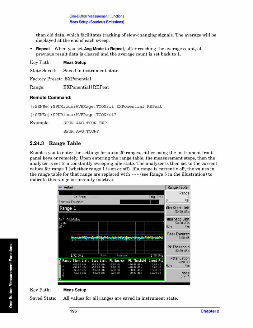
One-Button Measurement FunctionsMeas Setup (Spurious Emissions)
On
e-B
utt
on
Mea
sure
men
t F
un
ctio
ns
than old data, which facilitates tracking of slow-changing signals. The average will be displayed at the end of each sweep.
• Repeat—When you set Avg Mode to Repeat, after reaching the average count, all previous result data is cleared and the average count is set back to 1.
Key Path: Meas Setup
State Saved: Saved in instrument state.
Factory Preset: EXPonential
Range: EXPonential|REPeat
Remote Command:
[:SENSe]:SPURious:AVERage:TCONrol EXPonential|REPeat
[:SENSe]:SPURious:AVERage:TCONrol?
Example: SPUR:AVG:TCON EXP
SPUR:AVG:TCON?
2.24.3 Range Table
Enables you to enter the settings for up to 20 ranges, either using the instrument front panel keys or remotely. Upon entering the range table, the measurement stops, then the analyzer is set to a constantly sweeping idle state. The analyzer is then set to the current values for range 1 (whether range 1 is on or off). If a range is currently off, the values in the range table for that range are replaced with --- (see Range 5 in the illustration) to indicate this range is currently inactive.
Key Path: Meas Setup
Saved State: All values for all ranges are saved in instrument state.
196 Chapter 2
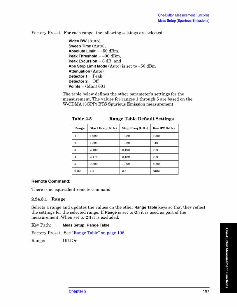
One-Button Measurement FunctionsMeas Setup (Spurious Emissions)
On
e-Bu
tton
Measu
remen
t Fu
nctio
Factory Preset: For each range, the following settings are selected:
Video BW (Auto), Sweep Time (Auto), Absolute Limit = −50 dBm, Peak Threshold = −90 dBm, Peak Excursion = 6 dB, and Abs Stop Limit Mode (Auto) is set to −50 dBmAttenuation (Auto)Detector 1 = PeakDetector 2 = OffPoints = (Man) 601
The table below defines the other parameter’s settings for the measurement. The values for ranges 1 through 5 are based on the W-CDMA (3GPP) BTS Spurious Emission measurement.
Remote Command:
There is no equivalent remote command.
2.24.3.1 Range
Selects a range and updates the values on the other Range Table keys so that they reflect the settings for the selected range. If Range is set to On it is used as part of the measurement. When set to Off it is excluded.
Key Path: Meas Setup, Range Table
Factory Preset: See “Range Table” on page 196.
Range: Off|On
Table 2-5 Range Table Default Settings
Range Start Freq (GHz) Stop Freq (GHz) Res BW (kHz)
1 1.920 1.980 1200
2 1.894 1.920 510
3 2.100 2.102 100
4 2.175 2.180 100
5 0.800 1.000 4000
6-20 1.5 2.5 Auto
Chapter 2 197
ns
One-Button Measurement FunctionsMeas Setup (Spurious Emissions)
On
e-B
utt
on
Mea
sure
men
t F
un
ctio
ns
Remote Command:
This parameter can receive up to 20 values. The location in the list sent corresponds to the range the value is associated with. Missing values are not permitted. For example, if you want to change values 2 and 6, you must send all values up to 6. Subsequent values remain as they were.
[:SENSe]:SPURious[:RANGe][:LIST]:STATe OFF|ON|0|1
The query for this parameter will always return 20 values.
[:SENSe]:SPURious[:RANGe][:LIST]:STATe?
Example: SPUR:STAT OFF,ON,ON,OFF,ON,ONlists values 1 through 6
2.24.3.2 Start Freq
Used to set the start frequency of the analyzer.
Key Path: Meas Setup, Range Table
Factory Preset: See “Range Table” on page 196.
Knob Increment: 1%
Step Key Increment: 1, 1.5, 2, 3, 5, 7.5, 10,...
Range: Frequency range of your analyzer.
Remote Command:
This parameter can receive up to 20 values. The location in the list sent corresponds to the range the value is associated with. Missing values are not permitted, for example, if you want to change values 2 and 6, you must send all values up to 6. Subsequent values will remain as they were.
[:SENSe]:SPURious[:RANGe][:LIST]:FREQuency:STARt <freq>, <freq>,... (up to 20 frequencies)
The query for this parameter will always return 20 values.
[:SENSe]:SPURious[:RANGe][:LIST]:FREQuency:STARt?
2.24.3.3 Stop Freq
Stop Freq is used to set the stop frequency of the analyzer.
Key Path: Meas Setup, Range Table
Factory Preset: See “Range Table” on page 196.
Knob Increment: 1%
Step Key Increment: 1, 1.5, 2, 3, 5, 7.5, 10,...
Range: Frequency range of your analyzer.
198 Chapter 2
One-Button Measurement FunctionsMeas Setup (Spurious Emissions)
On
e-Bu
tton
Measu
remen
t Fu
nctio
Remote Command:
This parameter can receive up to 20 values. The location in the list sent corresponds to the range the value is associated with. Missing values are not permitted, for example, if you want to change values 2 and 6, you must send all values up to 6. Subsequent values will remain as they were.
[:SENSe]:SPURious[:RANGe][:LIST]:FREQuency:STOP <freq>, <freq>... (up to 20 frequencies)
The query for this parameter will always return 20 values.
[:SENSe]:SPURious[:RANGe][:LIST]:FREQuency:STOP?
2.24.3.4 Res BW
Res BW is used to set the resolution bandwidth of the analyzer. When Auto is selected the analyzer determines the optimum setting, while Man enables you to determine the setting.
Key Path: Meas Setup, Range Table
Factory Preset: See “Range Table” on page 196.
Knob Increment: Steps through the available resolution bandwidth filters.
Step Key Increment: Steps through the available resolution bandwidth filters.
Range: Resolution bandwidth range of your analyzer.
Remote Command:
This parameter can receive up to 20 values. The location in the list sent corresponds to the range the value is associated with. Missing values are not permitted, for example, if you want to change values 2 and 6, you must send all values up to 6. Subsequent values will remain as they were.
[:SENSe]:SPURious[:RANGe][:LIST]:BANDwidth[:RESolution]:AUTO OFF|ON|0|1 selects the mode.
[:SENSe]:SPURious[:RANGe][:LIST]:BANDwidth[:RESolution] <freq>, <freq>,... (up to 20 frequencies)
The query for this parameter always returns 20 values.
[:SENSe]:SPURious[:RANGe][:LIST]:BANDwidth[:RESolution]:AUTO?
[:SENSe]:SPURious[:RANGe][:LIST]:BANDwidth[:RESolution]?
2.24.3.5 Video BW
Video BW is used to set the video bandwidth of the analyzer. When Auto is selected the analyzer determines the optimum setting, while Man enables you to determine the setting.
Key Path: Meas Setup, Range Table
Factory Preset: See “Range Table” on page 196.
Knob Increment: Steps through the available video bandwidth filters.
Chapter 2 199
ns

One-Button Measurement FunctionsMeas Setup (Spurious Emissions)
On
e-B
utt
on
Mea
sure
men
t F
un
ctio
ns
Step Key Increment: Steps through the available video bandwidth filters.
Range: Video bandwidth range of your analyzer.
Remote Command:
This parameter can receive up to 20 values. The location in the list sent corresponds to the range the value is associated with. Missing values are not permitted, for example, if you want to change values 2 and 6, you must send all values up to 6. Subsequent values will remain as they were.
[:SENSe]:SPURious[:RANGe][:LIST]:BWIDth|BANDwidth:VIDeo:AUTO OFF|ON|0|1 selects the mode.
[:SENSe]:SPURious[:RANGe][:LIST]:BWIDth|BANDwidth:VIDeo <freq>, <freq>,... (up to 20 frequencies)
The query for this parameter will always return 20 values.
[:SENSe]:SPURious[:RANGe][:LIST]:BWIDth|BANDwidth:VIDeo:AUTO?
[:SENSe]:SPURious[:RANGe][:LIST]:BWIDth|BANDwidth:VIDeo?
2.24.3.6 Sweep Time
Sweep Time is used to set the sweep time of the analyzer. When Auto is selected the analyzer determines the optimum setting, while Man enables you to determine the setting.
Key Path: Meas Setup, Range Table
Factory Preset: See “Range Table” on page 196.
Knob Increment: 1%
Step Key Increment: 1, 1.5, 2, 3, 5, 7.5, 10,...
Range: Sweep time range of your analyzer.
Remote Command:
[:SENSe]:SPURious[:RANGe][:LIST]:SWEep:TIME:AUTO OFF|ON|0|1, OFF|ON|0|1
[:SENSe]:SPURious[:RANGe][:LIST]:SWEep:TIME:AUTO?
[:SENSe]:SPURious[:RANGe][:LIST]:SWEep:TIME: <time>, <time>,... (up to 20 sweeptimes)
[:SENSe]:SPURious[:RANGe][:LIST]:SWEep:TIME?
Remote Command Notes: This parameter can receive up to 20 values. The location in the list sent
corresponds to the range the value is associated with. Missing values are not permitted, for example, if you want to change values 2 and 6, you must send all values up to 6. Subsequent values will remain as they were.
The query for this parameter will always return 20 values.
Example: [:SENSe]:SPURious[:RANGe][:LIST]:SWEep:TIME:AUTO ON,OFF,ON
[:SENSe]:SPURious[:RANGe][:LIST]:SWEep:TIME: 4ms,10ms
200 Chapter 2
One-Button Measurement FunctionsMeas Setup (Spurious Emissions)
On
e-Bu
tton
Measu
remen
t Fu
nctio
2.24.3.7 Abs Start Limit
Abs Start Limit is used to set the absolute start limit to the set value, then sets the absolute stop limit to the same value as the start limit. Any spurs located above the current setting of Peak Excursn and Threshold will be added to the results table. A red F will be appended to the amplitude value of the spur if the measured amplitude of the spur is above the limit set with Abs Start Limit.
Key Path: Meas Setup, Range Table
Dependencies/Couplings: If the limit is set to Auto, Abs Start Limit and Abs Stop Limit
are coupled to make a flat limit line. If set to Man, the absolute start and stop limits can take different values to make a sloped limit line.
Factory Preset: See “Range Table” on page 196.
Knob Increment: 0.1 dB
Step Key Increment: 1 dB
Range: –150 dBm to 50 dBm
History: Added with PSA firmware revision A.03.00
Added with ESA firmware revision A.09.00
Remote Command:
:CALCulate:SPURious[:RANGe][:LIST]:LIMit:ABSolute[:UPPER]:DATA:STARt <integer>, <integer>,...
:CALCulate:SPURious[:RANGe][:LIST]:LIMit:ABSolute[:UPPER]:DATA:STARt?
Remote Command Notes: This parameter can receive up to 20 values. The location in the list sent
corresponds to the range the value is associated with. Missing values are not permitted, for example, if you want to change values 2 and 6, you must send all values up to 6. Subsequent values will remain as they were.
The query for this parameter will always return 20 values.
Related commands are [:SENSe]:SPURious[:RANGe][:LIST]:SWEep:TIME:AUTO?
[:SENSe]:SPURious[:RANGe][:LIST]:SWEep:TIME?
2.24.3.8 Abs Stop Limit
Abs Stop Limit is used to determine the limit above which spurs will report a failure. If any spurs are located above the current setting of Peak Excursn will be added to the results table. A red F will be appended to the amplitude value of the spur if the measured amplitude of the spur is above the limit set with Abs Stop Limit.
Chapter 2 201
ns
One-Button Measurement FunctionsMeas Setup (Spurious Emissions)
On
e-B
utt
on
Mea
sure
men
t F
un
ctio
ns
Key Path: Meas Setup, Range Table
Dependencies/Couplings: If the limit is set to Auto, Abs Start Limit and Abs Stop Limit are coupled to
make a flat limit line. If set to Man, the absolute start and stop limits can take different values to make a sloped limit line.
Factory Preset: See “Range Table” on page 196.
Knob Increment: 0.1 dB
Step Key Increment: 1 dB
Range: –150 dBm to 50 dBm
History: Added with PSA firmware revision A.03.00
Added with ESA firmware revision A.09.00
Remote Command:
:CALCulate:SPURious[:RANGe][:LIST]:LIMit:ABSolute[:UPPER]:DATA:STOP <integer>,<integer>,...
:CALCulate:SPURious[:RANGe][:LIST]:LIMit:ABSolute[:UPPER]:DATA:STOP?
:CALCulate:SPURious[:RANGe][:LIST]:LIMit:ABSolute[:UPPER]:DATA:STOP:AUTO OFF|ON|0|1, OFF|ON|0|1
:CALCulate:SPURious[:RANGe][:LIST]:LIMit:ABSolute[:UPPER]:DATA:STOP:AUTO?
Remote Command Notes: This parameter can receive up to 20 values. The location in the list sent corresponds to the range the value is associated with. Missing values are not permitted, for example, if you want to change values 2 and 6, you must send all values up to 6. Subsequent values will remain as they were.
The query for this command will always return 20 values.
Example: :CALC:SPUR:LIM:ABS:DATA -23,-27
:CALC:SPUR:LIM:ABS:DATA:AUTO ON, ON, ON, ON
2.24.3.9 Peak Excursn
Peak Excursn sets the minimum amplitude variation of signals that can be identified as peaks. For example, if a value of 6 dB is selected, peaks that rise and fall more than the 6 dB above the peak threshold value are identified.
Key Path: Meas Setup, Range Table
Factory Preset: See “Range Table” on page 196.
Knob Increment: 1 dB
Step Key Increment: 1 dB
Range: 0.0 dB to 100.0 dB
202 Chapter 2
One-Button Measurement FunctionsMeas Setup (Spurious Emissions)
On
e-Bu
tton
Measu
remen
t Fu
nctio
Remote Command:
This parameter can receive up to 20 values. The location in the list sent corresponds to the range the value is associated with. Missing values are not permitted, for example, if you want to change values 2 and 6, you must send all values up to 6. Subsequent values will remain as they were.
[:SENSe]:SPURious[:RANGe][:LIST]:PEAK:EXCursion <integer>, <integer>,...
The query for this parameter will always return 20 values.
[:SENSe]:SPURious[:RANGe][:LIST]:PEAK:EXCursion?
2.24.3.10 Pk Threshold
Pk Threshold sets the minimum amplitude of signals that can be identified as peaks. For example, if a value of -90 dBm is selected, only peaks that rise and fall more than the peak excursion value and are above the Pk Threshold of −90 dBm are identified.
Key Path: Meas Setup, Range Table
Factory Preset: See “Range Table” on page 196.
Knob Increment: 1 dB
Step Key Increment: 1 dB
Range: –100 dB to 0.0 dB
Remote Command:
This parameter can receive up to 20 values. The location in the list sent corresponds to the range the value is associated with. Missing values are not permitted, for example, if you want to change values 2 and 6, you must send all values up to 6. Subsequent values will remain as they were.
[:SENSe]:SPURious[:RANGe][:LIST]:PEAK:THReshold <integer>, <integer>,...
The query for this parameter will always return 20 values.
[:SENSe]:SPURious[:RANGe][:LIST]:PEAK:THReshold?
2.24.3.11 Attenuation
PSA Only: Attenuation sets the attenuation for each range. This parameter can send up to 20 values. The location in the list sent corresponds to the range the value is associated with. Missing values are not permitted, for example, if you want to change values 2 and 6 you must send all values up to 6. Subsequent values will remain as they were.
Key Type: Toggle
Key Path: Meas Setup, Range Table
State Saved: Saved in instrument state.
Factory Preset: Auto, the value is determined by the radio standard and the instrument model.
Chapter 2 203
ns
One-Button Measurement FunctionsMeas Setup (Spurious Emissions)
On
e-B
utt
on
Mea
sure
men
t F
un
ctio
ns
Knob Increment: 2 dB
Step Key Increment: 2 dB
Range: 0 to 70 dB
History: Added with PSA firmware revision A.06.00
Remote Command:
[:SENSe]:SPURious[:RANGe][:LIST]:ATTenuation <integer>, <integer>,...
[:SENSe]:SPURious[:RANGe][:LIST]:ATTenuation?
Remote Command Notes: The query always returns 20 values
Example: SPUR:RANG:LIST:ATT 20,20,20,20,20,20
2.24.3.12 Detector 1
PSA Only: Allows you to set the detector to be used by the trace which will be used for display purposes only.
The detector choices are:
• Normal − displays the peak of CW-like signals and maximums and minimums of noise-like signals.
• Average − displays the average of the signal within the sweep point (bucket). The averaging method depends upon Avg Type selection (voltage, power or log scales).
• Peak − displays the maximum of the signal within the sweep point (bucket).
• Sample − displays the instantaneous level of the signal at the center of the sweep point (bucket) represented by each display point.
• Negative Peak − displays the minimum of the signal within the sweep point (bucket).
• Quasi Peak − a fast-rise, slow-fall detector used in making CISPR compliant EMI measurements.
• EMI Average − displays the instantaneous level of the signal at the center of the sweep point (bucket), just like the sample detector. Also changes the auto coupling of VBW, RBW and Avg/VBW Type and the set of available RBWs. Used in making CISPR-compliant measurements.
• EMI Peak − the same as the Peak detector but uses CISPR related bandwidths.
• MIL Peak − the same as the Peak detector but uses MIL related bandwidths.
Key Path: Meas Setup, Range Table
State Saved: Saved in instrument state.
Factory Preset: Auto, the value is determined by the radio standard and the instrument model.
Knob Increment: 2 dB
Step Key Increment: 2 dB
204 Chapter 2
One-Button Measurement FunctionsMeas Setup (Spurious Emissions)
On
e-Bu
tton
Measu
remen
t Fu
nctio
Range: 0 to 70 dB
History: Added with PSA firmware revision A.06.00
Remote Command:
[:SENSe]:SPURious[:RANGe][:LIST]:POINts[:FUNCtion] NORMal|AVERage|POSitive|SAMPle|NEGative|QPEak|EAVerage|EPOSitive|MPositive
[:SENSe]:SPURious[:RANGe][:LIST]:DET?
Example: SPUR:POIN QPE
2.24.3.13 Detector 2
PSA Only: Allows you to set the detector to be used by the trace which will be used for display purposes only.
The detector choices are:
• Off − turns off second trace (Detector 2)
• Normal − displays the peak of CW-like signals and maximums and minimums of noise-like signals.
• Average − displays the average of the signal within the sweep point (bucket). The averaging method depends upon Avg Type selection (voltage, power or log scales).
• Peak − displays the maximum of the signal within the sweep point (bucket).
• Sample − displays the instantaneous level of the signal at the center of the sweep point (bucket) represented by each display point.
• Negative Peak − displays the minimum of the signal within the sweep point (bucket).
• Quasi Peak − a fast-rise, slow-fall detector used in making CISPR compliant EMI measurements.
• EMI Average − displays the instantaneous level of the signal at the center of the sweep point (bucket), just like the sample detector. Also changes the auto coupling of VBW, RBW and Avg/VBW Type and the set of available RBWs. Used in making CISPR-compliant measurements.
• EMI Peak − the same as the Peak detector but uses CISPR related bandwidths.
• MIL Peak − the same as the Peak detector but uses MIL related bandwidths.
Key Path: Meas Setup, Range Table
State Saved: Saved in instrument state.
Factory Preset: Auto, the value is determined by the radio standard and the instrument model.
Knob Increment: 2 dB
Step Key Increment: 2 dB
Range: 0 to 70 dB
Chapter 2 205
ns
One-Button Measurement FunctionsMeas Setup (Spurious Emissions)
On
e-B
utt
on
Mea
sure
men
t F
un
ctio
ns
History: Added with PSA firmware revision A.06.00
Remote Command:
[:SENSe]:SPURious[:RANGe][:LIST]:POINts[:FUNCtion] OFF|NORMal|AVERage|POSitive|SAMPle|NEGative|QPEak|EAVerage|EPOSitive|MPositive
[:SENSe]:SPURious[:RANGe][:LIST]:DET2?
Example: SPUR:DET2 EAV
2.24.3.13.1 Normal
PSA Only: Displays the peak-detected level in the interval (sweep points bucket) being displayed when the signal is CW-like. If the signal is noise-like (within an interval, sweep points bucket, the signal both rose and fell), the even sweep points bucket shows the peak (maximum) within a two-bucket interval, and the odd sweep points bucket shows the negative peak (minimum). Gain is increased to compensate for the effects of faster sweep rates, to keep the displayed value of CW signals accurate.
When Normal is selected, Norm appears on the left side of the display.
Key Path: Meas Setup, Range Table, Detector 1 or Detector 2
State Saved: Saved in instrument state.
History: Added with PSA firmware revision A.06.00
Remote Command:
See “Detector 2” on page 205.
2.24.3.13.2 Average
PSA Only: For each interval (sweep points bucket) in the trace, Average detection displays the average of all samples within the interval using one of the following averaging methods:
• log (also known as video)
• power (also known as RMS)
• voltage envelope
To explicitly set the averaging method, use the BW/Avg, Avg/VBW Type key. The combination of the average detector and the power method is equivalent to what is sometimes referred to as “RMS detection.” When the method (Avg/VBW Type) is set to Pwr Avg, and Detector is set to Average, the RMS method is selected.
When Average is selected, Avg appears on the left side of the display.
Key Path: Meas Setup, Range Table, Detector 1 or Detector 2
State Saved: Saved in instrument state.
History: Added with PSA firmware revision A.06.00
206 Chapter 2
One-Button Measurement FunctionsMeas Setup (Spurious Emissions)
On
e-Bu
tton
Measu
remen
t Fu
nctio
Remote Command:
See “Detector 2” on page 205.
2.24.3.13.3 Peak
PSA Only: For each interval (sweep points bucket) in the trace, Peak detection displays the highest amplitude within the interval. Peak detection is used for CW measurements and some pulsed-RF measurements. For swept analysis, peak detection basically obtains the maximum video signal between the end of the last sweep points bucket and the start of the next one. Gain is increased to compensate for the effects of faster sweep rates, to keep the displayed value accurate. For FFT analysis, the highest spectral amplitude is displayed, even if that peak amplitude falls between samples of the spectrum computed in the FFT process.
When Peak is selected, Peak appears on the left side of the display.
Key Path: Meas Setup, Range Table, Detector 1 or Detector 2
State Saved: Saved in instrument state.
History: Added with PSA firmware revision A.06.00
Remote Command:
See “Detector 2” on page 205.
2.24.3.13.4 Sample
PSA Only: The sample detector displays the instantaneous level of the signal at the center of the interval (sweep points bucket) represented by each trace point.
Sample detection is primarily used to display noise or noise-like signals.
Sample detection is not best for amplitude measurements of CW-like signals for two reasons. First, the peak response to a signal can occur between samples, so unless the Span to RBW ratio is lower than usual, the highest sample can be well below the peak signal amplitude. Second, for the high sweep rates normally used, the peak response of the RBW filters is up to –0.5 dB. This sweeping error is compensated when using the peak and normal detectors by changing the overall gain. But the gain is not changed when in the sample detector, because to do so would cause errors in the response to noise.
When Sample is selected, Samp appears on the left side of the display.
Key Path: Meas Setup, Range Table, Detector 1 or Detector 2
State Saved: Saved in instrument state.
History: Added with PSA firmware revision A.06.00
Remote Command:
See “Detector 2” on page 205.
2.24.3.13.5 Negative Peak
PSA Only: For each interval (sweep points bucket) in the trace, Negative Peak detection
Chapter 2 207
ns
One-Button Measurement FunctionsMeas Setup (Spurious Emissions)
On
e-B
utt
on
Mea
sure
men
t F
un
ctio
ns
displays the lowest sample within the interval.
When Negative Peak is selected, NPk appears on the left side of the display.
Key Path: Meas Setup, Range Table, Detector 1 or Detector 2
State Saved: Saved in instrument state.
History: Added with PSA firmware revision A.06.00
Remote Command:
See “Detector 2” on page 205.
2.24.3.13.6 Quasi Peak
PSA Only: Selects quasi peak detection. This is a fast-rise, slow-fall detector used in making CISPR compliant EMI measurements. Quasi peak detection displays a weighted amplitude using specific charge, discharge, and meter-movement time constants as described in CISPR Publication 16.
Key Path: Meas Setup, Range Table, Detector 1 or Detector 2
State Saved: Saved in instrument state.
History: Added with PSA firmware revision A.06.00
Remote Command:
See “Detector 2” on page 205.
2.24.3.13.7 EMI Average
PSA Only: Selects EMI averaging detection. EMI Average detection displays the average value of amplitude envelope. It is defined for EMI measurements by the CISPR standard and uses the VBW filter as a low pass filter, the output of which is sampled during the bucket interval. This functionality is quite different from the Average detector.
Key Path: Meas Setup, Range Table, Detector 1 or Detector 2
State Saved: Saved in instrument state.
History: Added with PSA firmware revision A.06.00
Remote Command:
See “Detector 2” on page 205.
2.24.3.13.8 EMI Peak
PSA Only: Selects peak detection using EMI specifications.
Key Path: Meas Setup, Range Table, Detector 1 or Detector 2
State Saved: Saved in instrument state.
History: Added with PSA firmware revision A.06.00
208 Chapter 2
One-Button Measurement FunctionsMeas Setup (Spurious Emissions)
On
e-Bu
tton
Measu
remen
t Fu
nctio
Remote Command:
See “Detector 2” on page 205.
2.24.3.13.9 MIL Peak
PSA Only: Selects peak detection using the MIL specifications.
Key Path: Meas Setup, Range Table, Detector 1 or Detector 2
State Saved: Saved in instrument state.
History: Added with PSA firmware revision A.06.00
Remote Command:
See “Detector 2” on page 205.
2.24.3.13.10 Off
PSA Only: Detector 2 is off, there is no second trace.
Key Path: Meas Setup, Range Table, Detector 2
State Saved: Saved in instrument state.
History: Added with PSA firmware revision A.06.00
Remote Command:
See “Detector 2” on page 205.
2.24.3.14 Points
PSA Only: Used to set the points mode of the analyzer. Setting to Man allows you to determine the setting, or by selecting Auto the analyzer will determine the number of trace points to ensure the sweep point (bucket) resolution equals RBW/2.
Key Path: Meas Setup, Range Table
State Saved: Saved in instrument state.
Factory Preset: Auto, the value is determined by the radio standard and the instrument model.
Knob Increment: 1
Step Key Increment: 1
Range: 101 to 8192
History: Added with PSA firmware revision A.06.00
Remote Command:
[:SENSe]:SPURious[:RANGe][:LIST]:SWEep:POINts <integer>, <integer>,...
[:SENSe]:SPURious[:RANGe][:LIST]:SWEep:POINts?
[:SENSe]:SPURious[:RANGe][:LIST]:SWEep:POINts:AUTO
Chapter 2 209
ns
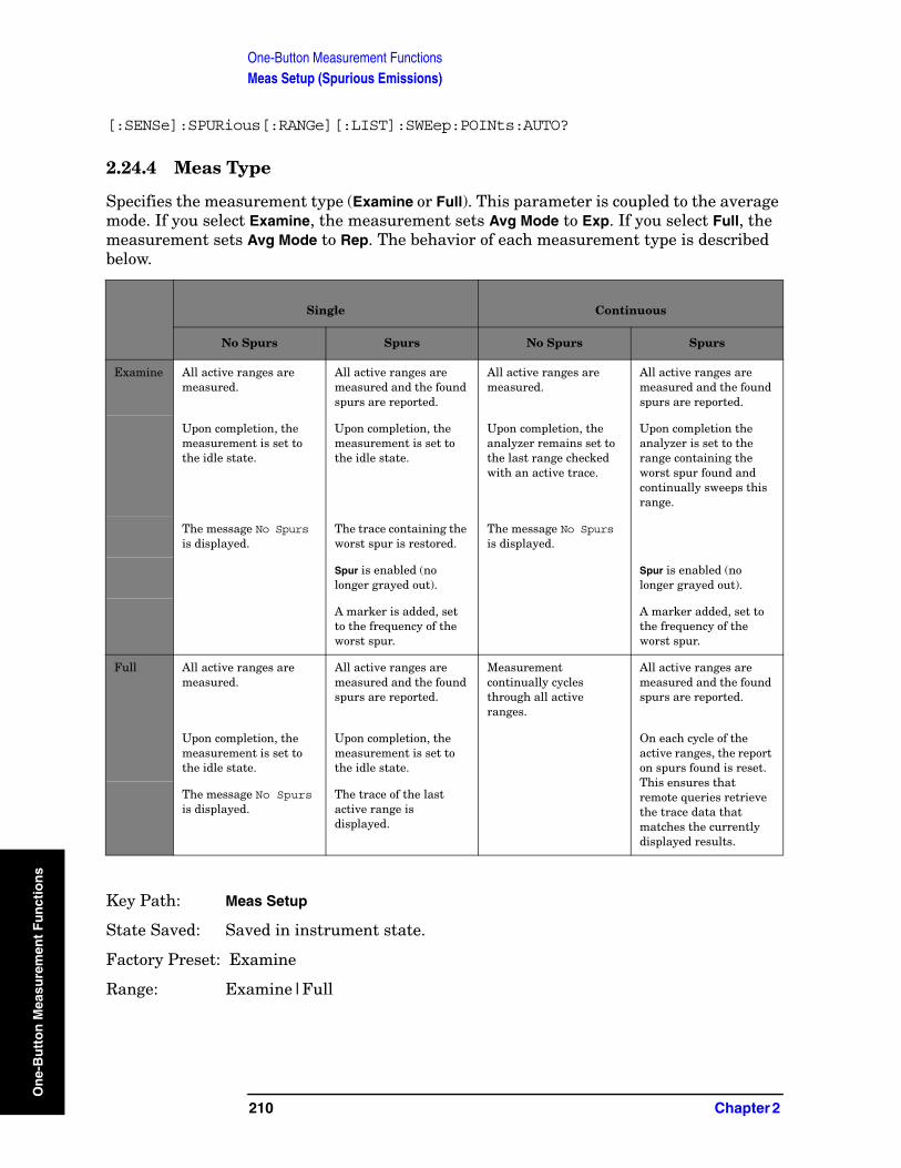
One-Button Measurement FunctionsMeas Setup (Spurious Emissions)
On
e-B
utt
on
Mea
sure
men
t F
un
ctio
ns
[:SENSe]:SPURious[:RANGe][:LIST]:SWEep:POINts:AUTO?
2.24.4 Meas Type
Specifies the measurement type (Examine or Full). This parameter is coupled to the average mode. If you select Examine, the measurement sets Avg Mode to Exp. If you select Full, the measurement sets Avg Mode to Rep. The behavior of each measurement type is described below.
Key Path: Meas Setup
State Saved: Saved in instrument state.
Factory Preset: Examine
Range: Examine|Full
Single Continuous
No Spurs Spurs No Spurs Spurs
Examine All active ranges are measured.
All active ranges are measured and the found spurs are reported.
All active ranges are measured.
All active ranges are measured and the found spurs are reported.
Upon completion, the measurement is set to the idle state.
Upon completion, the measurement is set to the idle state.
Upon completion, the analyzer remains set to the last range checked with an active trace.
Upon completion the analyzer is set to the range containing the worst spur found and continually sweeps this range.
The message No Spurs is displayed.
The trace containing the worst spur is restored.
The message No Spurs is displayed.
Spur is enabled (no longer grayed out).
Spur is enabled (no longer grayed out).
A marker is added, set to the frequency of the worst spur.
A marker added, set to the frequency of the worst spur.
Full All active ranges are measured.
All active ranges are measured and the found spurs are reported.
Measurement continually cycles through all active ranges.
All active ranges are measured and the found spurs are reported.
Upon completion, the measurement is set to the idle state.
Upon completion, the measurement is set to the idle state.
On each cycle of the active ranges, the report on spurs found is reset. This ensures that remote queries retrieve the trace data that matches the currently displayed results.
The message No Spurs is displayed.
The trace of the last active range is displayed.
210 Chapter 2
One-Button Measurement FunctionsMeas Setup (Spurious Emissions)
On
e-Bu
tton
Measu
remen
t Fu
nctio
Remote Command:
[:SENSe]:SPURious:TYPE EXAMine|FULL
[:SENSe]:SPURious:TYPE?
Remote Command Notes n/a
Example: SPUR:TYPE FULL
2.24.5 Spur
Enables you to view any spurs that have been found. The measurement sets the analyzer to the range in which the currently selected spur was found. The range settings changes only if the selected spur is in the range that is different from the current range settings. A marker identifies the currently selected spur on the trace.
NOTE This key is enabled only when Meas Type is set to Examine, and only upon completion of a measurement.
Key Path: Meas Setup
Saved State: No values are saved to state.
Factory Preset: 1
Knob Increment: 1
Step Key Increment: 1
Range: 1 to 200, 10 per range
Remote Command:
[:SENSe]:SPURious:SPUR <integer>
[:SENSe]:SPURious:SPUR?
2.24.6 Ref Level
Pressing Ref Level sets the reference level of the analyzer.
Key Path: Meas Setup
Saved State: Ref Level state is saved to instrument state. Ref Level value is recalculated for each active range the value is not stored in instrument state.
Factory Preset: 0.00 dBm
Knob Increment: 1
Step Key Increment: 10
Range: –180 dBm to 20 dBm, without reference level offset
Chapter 2 211
ns
One-Button Measurement FunctionsMeas Setup (Spurious Emissions)
On
e-B
utt
on
Mea
sure
men
t F
un
ctio
ns
Remote Command:
[:SENSe]:SPURious:POWer[:RF]:LEVel <integer>
[:SENSe]:SPURious:POWer[:RF]:LEVel?
[:SENSe]:SPURious:POWer[:RF]:RANGe:AUTO OFF|ON|0|1
[:SENSe]:SPURious:POWer[:RF]:RANGe:AUTO?
Example: SPUR:POW:RF:LEV 10
SPUR:POW:RF:RANG:AUTO ON
2.24.7 Fast Spurious Meas
Pressing Fast Spurious Meas turns the fast spurious measurement test on or off. Pressing Fast Spurious Meas to On provides a faster method of execution as with fast spurious testing spurs above the limit line are reported. Any spurs reported outside the limit will cause the measurement to fail. See “Abs Start Limit” on page 201 for more information.
Key Path: Meas Setup
Saved State: Ref Level state is saved to instrument state. Ref Level value is recalculated for each active range the value is not stored in instrument state.
Factory Preset: Off
Range: Off|On
History: Add with PSA firmware revision A.03.00
Remote Command:
[:SENSe]:SPURious:FSMeas OFF|ON|0|1
[:SENSe]:SPURious:FSMeas?
Example: SPUR:FSM ON
212 Chapter 2

One-Button Measurement FunctionsDisplay (Spurious Emissions) for PSA Only
On
e-Bu
tton
Measu
remen
t Fu
nctio
2.25 Display (Spurious Emissions) for PSA Only
Displays menu keys that enable you to configure parameters for the spurious emissions measurement.
NOTE The keys described below are measurement dependent. To access the display menus, for the spurious emissions measurement press MEASURE, Spurious Emissions, then Display.
2.25.1 Full Screen
Expands the measurement window horizontally over the entire instrument display. Pressing any other key that results in a new menu cancels the full screen function.
Key Path: Display
State Saved: Not saved in state.
Factory Preset: Off
Factory Default: Off
History: Added with PSA firmware revision A.06.00
2.25.2 Preferences
Displays menu keys that enable you to turn the graticule and annotation on or off.
Key Path: Display
State Saved: Saved in instrument state.
History: Added with PSA firmware revision A.06.00
2.25.2.1 Graticule (On Off)
Pressing Graticule turns the display graticules On or Off.
Key Path: Display, Preferences
Factory Preset: On
Factory Default: On
Terminators: Enter
History: Added with PSA firmware revision A.06.00
Chapter 2 213
ns

One-Button Measurement FunctionsDisplay (Spurious Emissions) for PSA Only
On
e-B
utt
on
Mea
sure
men
t F
un
ctio
ns
2.25.2.2 Annotation (On Off)
Turns the screen annotation on or off, however, the menu key annotation will remain on the display. The screen annotation may not be required for prints or during remote operation.
Key Path: Display
Factory Presetand *RST: On
Factory Default: On
Terminators: Enter
History: Added with PSA firmware revision A.06.00
214 Chapter 2
One-Button Measurement FunctionsMarker (Spurious Emissions) for PSA Only
On
e-Bu
tton
Measu
remen
t Fu
nctio
2.26 Marker (Spurious Emissions) for PSA Only
Displays the Marker control menu for the spurious emissions measurement. If no markers are active, Marker selects marker 1, sets it to Normal and places it to the right of the display. There are two control modes for the markers:
• Normal (POSition) - A single marker that can be moved to any point on the trace.
• Delta (DELTa) - Places the selected marker and the next marker at the position of the previous marker on the specified trace (selected by pressing Marker Trace). The next marker is the reference marker (set to normal) and the selected marker is a moveable marker (delta) that you can place at any point on the trace. The difference between the selected marker and the reference marker is displayed.
• Off (Off) - Turns off the active marker or marker pair.
Key Path: Front-panel key
State Saved: The control mode for each marker, as well as the position of each marker, is saved in instrument state.
Factory Preset: All Off.
History: Added with PSA firmware revision A.06.00
Remote Command:
There is no equivalent remote command.
2.26.1 Select Marker
Selects one of the four possible markers. Once a marker is selected, it can be set to any of the control modes Normal or Off.
Key Path: Marker
State Saved: The number of the selected marker is saved in instrument state.
Factory Preset: Marker 1
History: Added with PSA firmware revision A.06.00
Remote Command:
:CALCulate:SPURious:MARKer[1]|2|3|4:STATe OFF|ON|0|1
:CALCulate:SPURious:MARKer[1]|2|3|4:STATe?
Chapter 2 215
ns
One-Button Measurement FunctionsMarker (Spurious Emissions) for PSA Only
On
e-B
utt
on
Mea
sure
men
t F
un
ctio
ns
Remote Command Notes: Sets or queries the state of a marker. Setting a marker to state ON or 1
selects that marker. Setting a marker which is OFF to state ON or 1 puts it in Normal mode and places it on the screen to the right of the displayed measurement graph. Setting a marker to state OFF or 0 selects that marker and turns it off. The response to the query will be 0 if OFF, 1 if ON.
Example: CALC:SPUR:MARK2:STAT ON selects marker 2.
CALC:SPUR:MARK:STAT ON will not modify a marker that is already on.
2.26.2 Normal
Sets the control mode for the selected marker to Normal (see “Select Marker” on page 215). If the marker is off, a single marker is activated and placed on the screen to the right of the measurement graph. You can then adjust the trace point of the marker using the knob, numeric keypad, or ⇑ ⇓ keys.
Key Path: Marker
Factory Preset: Off
History: Added with PSA firmware revision A.06.00
Remote Command:
See “Marker (Spurious Emissions) for PSA Only” on page 215 for the mode command.
Example: CALC:SPUR:MARK:STAT ON selects marker 1 and sets it to Normal.
2.26.3 Delta
Sets the control mode for the selected marker to Delta. In Delta mode the display shows the difference between the active (Delta) marker and a reference marker. Annotation in the active function block and in the upper-right corner of the display indicates the power ratio (dB) difference and probability (percentage) difference of the two markers.
Key Path: Marker (after MEASURE, Spurious Emissions is selected.)
History: Added with PSA firmware revision A.08.00
Remote Command:
See Volume 1, Core Spectrum Analyzer Functions User’s and Programmer’s Reference guide.
Example: CALC:SPUR:MARK3:MODE DELT selects marker 3 as a delta marker and places a reference marker at the 0 dB point on the specified trace (see “Marker Trace” on page 116). If marker 3 is OFF it places both the active and the reference markers at the 0 dB point of the specified trace.
216 Chapter 2
One-Button Measurement FunctionsMarker (Spurious Emissions) for PSA Only
On
e-Bu
tton
Measu
remen
t Fu
nctio
2.26.4 Off
Turns off the selected marker. In addition, Off also turns off functions related to the selected marker.
Key Path: Marker
Factory Preset: Off
History: Added with PSA firmware revision A.06.00
Remote Command:
See “Select Marker” on page 215 for the command to select the control mode.
Example: CALC:SPUR:MARK3:STAT OFF selects marker 3 and sets it to Off.
2.26.5 Markers All Off
Turns off all markers.
NOTE Selecting any measurement (including Meas Off) under the Measure menu, turns off the marker table.
Key Path: Marker (after MEASURE, Power Stat CCDF is selected.)
History: Added with PSA firmware revision A.06.00
Remote Command:
:CALCulate:SPURious:MARKer[1]|2|3|4:AOFF
Example: CALC:SPUR:MARK:AOFF turns off all markers.
Chapter 2 217
ns
One-Button Measurement FunctionsMarker (Spurious Emissions) for PSA Only
On
e-B
utt
on
Mea
sure
men
t F
un
ctio
ns
2.26.6 Marker Mode
Sets the mode for the specified marker. When a marker is set to Delta, the next marker is used as the Reference Marker and its mode is set to Normal. The value of the delta marker is the relative value from the reference marker. When Marker4 is set to Delta, Marker1 is used as the Reference Marker.
NOTE Selecting any measurement (including Meas Off) under the Measure menu, turns off the marker table.
Key Path: Marker (after MEASURE, Power Stat CCDF is selected.)
History: Added with PSA firmware revision A.06.00
Remote Command:
:CALCulate:SPURious:MARKer[1]|2|3|4:AOFF
Example: CALC:SPUR:MARK:AOFF turns off all markers.
218 Chapter 2
Men
u M
aps: O
ne-B
utto
n M
easurem
ent
Fu
nctio
ns
3 Menu Maps: One-Button Measurement Functions
This chapter provides you with menu maps for all measurements available to you when you press the front-panel MEASURE key.
219
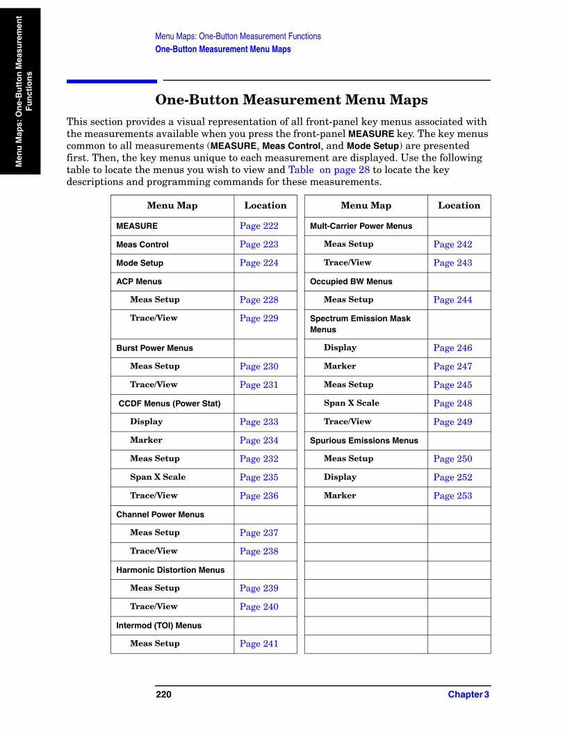
Menu Maps: One-Button Measurement FunctionsOne-Button Measurement Menu Maps
Men
u M
aps:
On
e-B
utt
on
Mea
sure
men
t F
un
ctio
ns
One-Button Measurement Menu MapsThis section provides a visual representation of all front-panel key menus associated with the measurements available when you press the front-panel MEASURE key. The key menus common to all measurements (MEASURE, Meas Control, and Mode Setup) are presented first. Then, the key menus unique to each measurement are displayed. Use the following table to locate the menus you wish to view and Table on page 28 to locate the key descriptions and programming commands for these measurements.
Menu Map Location Menu Map Location
MEASURE Page 222 Mult-Carrier Power Menus
Meas Control Page 223 Meas Setup Page 242
Mode Setup Page 224 Trace/View Page 243
ACP Menus Occupied BW Menus
Meas Setup Page 228 Meas Setup Page 244
Trace/View Page 229 Spectrum Emission Mask Menus
Burst Power Menus Display Page 246
Meas Setup Page 230 Marker Page 247
Trace/View Page 231 Meas Setup Page 245
CCDF Menus (Power Stat) Span X Scale Page 248
Display Page 233 Trace/View Page 249
Marker Page 234 Spurious Emissions Menus
Meas Setup Page 232 Meas Setup Page 250
Span X Scale Page 235 Display Page 252
Trace/View Page 236 Marker Page 253
Channel Power Menus
Meas Setup Page 237
Trace/View Page 238
Harmonic Distortion Menus
Meas Setup Page 239
Trace/View Page 240
Intermod (TOI) Menus
Meas Setup Page 241
220 Chapter 3
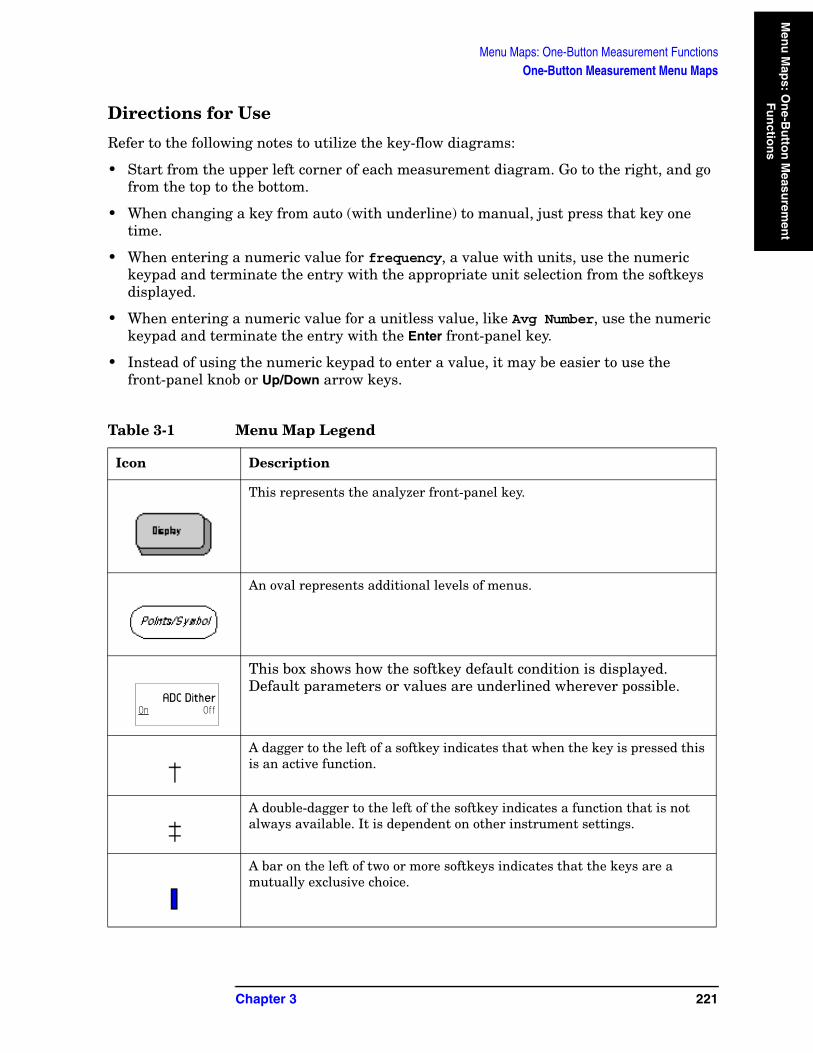
Menu Maps: One-Button Measurement FunctionsOne-Button Measurement Menu Maps
Men
u M
aps: O
ne-B
utto
n M
easurem
ent
Fu
nctio
ns
Directions for Use
Refer to the following notes to utilize the key-flow diagrams:
• Start from the upper left corner of each measurement diagram. Go to the right, and go from the top to the bottom.
• When changing a key from auto (with underline) to manual, just press that key one time.
• When entering a numeric value for frequency, a value with units, use the numeric keypad and terminate the entry with the appropriate unit selection from the softkeys displayed.
• When entering a numeric value for a unitless value, like Avg Number, use the numeric keypad and terminate the entry with the Enter front-panel key.
• Instead of using the numeric keypad to enter a value, it may be easier to use the front-panel knob or Up/Down arrow keys.
Table 3-1 Menu Map Legend
Icon Description
This represents the analyzer front-panel key.
An oval represents additional levels of menus.
This box shows how the softkey default condition is displayed. Default parameters or values are underlined wherever possible.
A dagger to the left of a softkey indicates that when the key is pressed this is an active function.
A double-dagger to the left of the softkey indicates a function that is not always available. It is dependent on other instrument settings.
A bar on the left of two or more softkeys indicates that the keys are a mutually exclusive choice.
ADC DitherOn Off
Chapter 3 221

222C
hap
ter 3
Menu M
aps: One-Button M
easurement Functions
One-Button M
easurement M
enu Maps
Menu Maps: One-Button Measurement Functions
MEASURE Key
Measure
Channel Power
Harmonic DistortionMeas Off
ACP
Occupied BW
Power Stat CCDF
MEASURE
Multi Carrier Power
More1 of 2
Burst Power
Intermod(TOI)
Spurious Emissions
Spectrum Emission
Mask
More2 of 2
Measure
measurements
‡
‡
‡
‡
‡
‡
‡
‡
‡
‡

Ch
apter 3
223
Menu M
aps: One-Button M
easurement Functions
One-Button M
easurement M
enu Maps
Menu Maps: One-Button Measurement Functions
Meas Control Key
Restart
MeasureSingle Cont
Pause
Meas Control
Key toggles betweenPause and Resume
MeasControl
pe883a
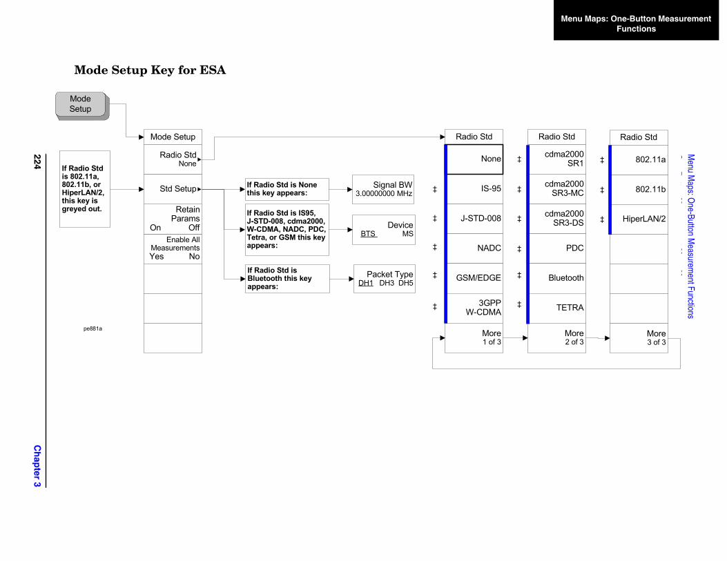
224C
hap
ter 3
Menu M
aps: One-Button M
easurement Functions
One-Button M
easurement M
enu Maps
Menu Maps: One-Button Measurement Functions
5
8
e3
cdma2000SR1
cdma2000SR3-MC
cdma2000SR3-DS
PDC
Bluetooth
TETRA
More2 of 3
Radio Std
‡
‡
‡
‡
‡
Radio Std
802.11a
802.11b
HiperLAN/2
More3 of 3
e
‡
‡
‡
‡
Mode Setup Key for ESA
Mode Setup
Mode Setup
Enable All MeasurementsYes No
Retain Params
On Off
Radio StdNone
Std Setup IS-9
J-STD-00
NADC
GSM/EDGE
3GPP W-CDMA
Mor1 of
Radio Std
If Radio Std is None this key appears:
Signal BW3.00000000 MHz
If Radio Std is Bluetooth this key appears:
Packet TypeDH1 DH3 DH5
If Radio Std is IS95, J-STD-008, cdma2000, W-CDMA, NADC, PDC, Tetra, or GSM this key appears:
DeviceBTS MS
‡
‡
‡
‡
‡
NonIf Radio Std is 802.11a, 802.11b, or HiperLAN/2, this key is greyed out.
pe881a
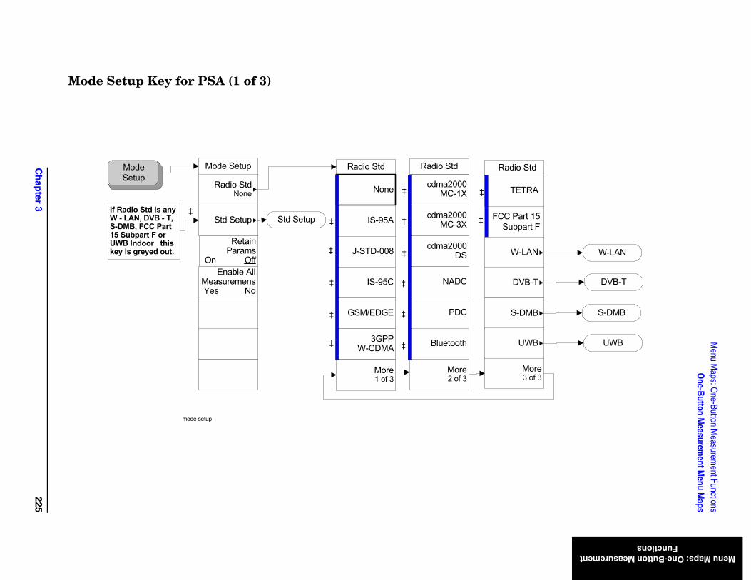
Ch
apter 3
225
Menu M
aps: One-Button M
easurement Functions
One-Button M
easurement M
enu Maps
Menu Maps: One-Button Measurement Functions
rt 15art F
Std
More3 of 3
TRA
LAN
B-T
MB
WB
W-LAN
DVB-T
S-DMB
UWB
Mode Setup Key for PSA (1 of 3)
Mode SetupMode Setup
Enable AllMeasuremensYes No
Retain Params
On Off
Radio StdNone
Std Setup IS-95A
J-STD-008
IS-95C
GSM/EDGE
3GPP W-CDMA
More1 of 3
cdma2000MC-1X
cdma2000MC-3X
cdma2000DS
NADC
PDC
Bluetooth
More2 of 3
Radio Std Radio Std
FCC PaSubp
Radio
None
If Radio Std is any W - LAN, DVB - T, S-DMB, FCC Part 15 Subpart F or UWB Indoor this key is greyed out.
TE
Std Setup
W-
DV
S-D
U
mode setup
‡‡
‡
‡
‡
‡
‡
‡
‡
‡
‡
‡
‡
‡
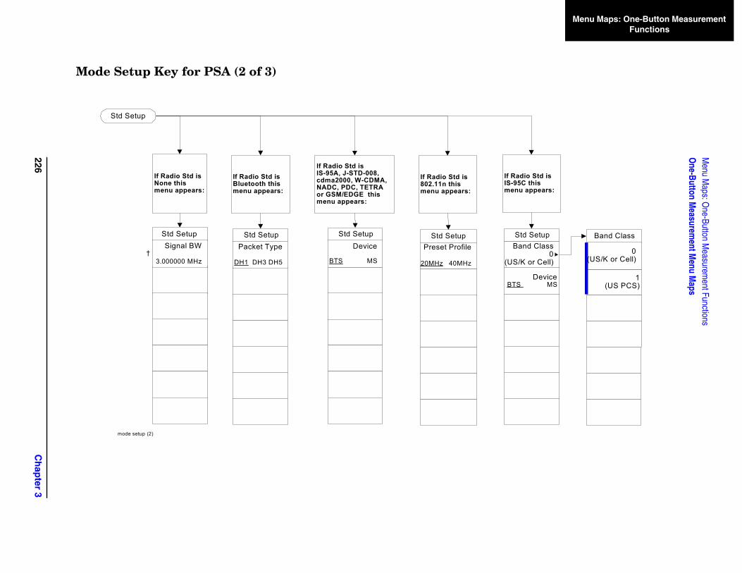
226C
hap
ter 3
Menu M
aps: One-Button M
easurement Functions
One-Button M
easurement M
enu Maps
Menu Maps: One-Button Measurement Functions
1(US PCS)
Band Class
0(US/K or Cell)
f Radio Std is S-95C this
enu appears:
DeviceBTS MS
Std SetupBand Class
0US/K or Cell)
Mode Setup Key for PSA (2 of 3)
If Radio Std is None this menu appears:
If Radio Std is Bluetooth this menu appears:
If Radio Std isIS-95A, J-STD-008, cdma2000, W-CDMA, NADC, PDC, TETRAor GSM/EDGE this menu appears:
Std SetupSignal BW
3.000000 MHz
Std SetupDevice
BTS MS
Std SetupPacket Type
DH1 DH3 DH5
IIm
Std Setup
(
mode setup (2)
†
If Radio Std is 802.11n this menu appears:
Std SetupPreset Profile
20MHz 40MHz
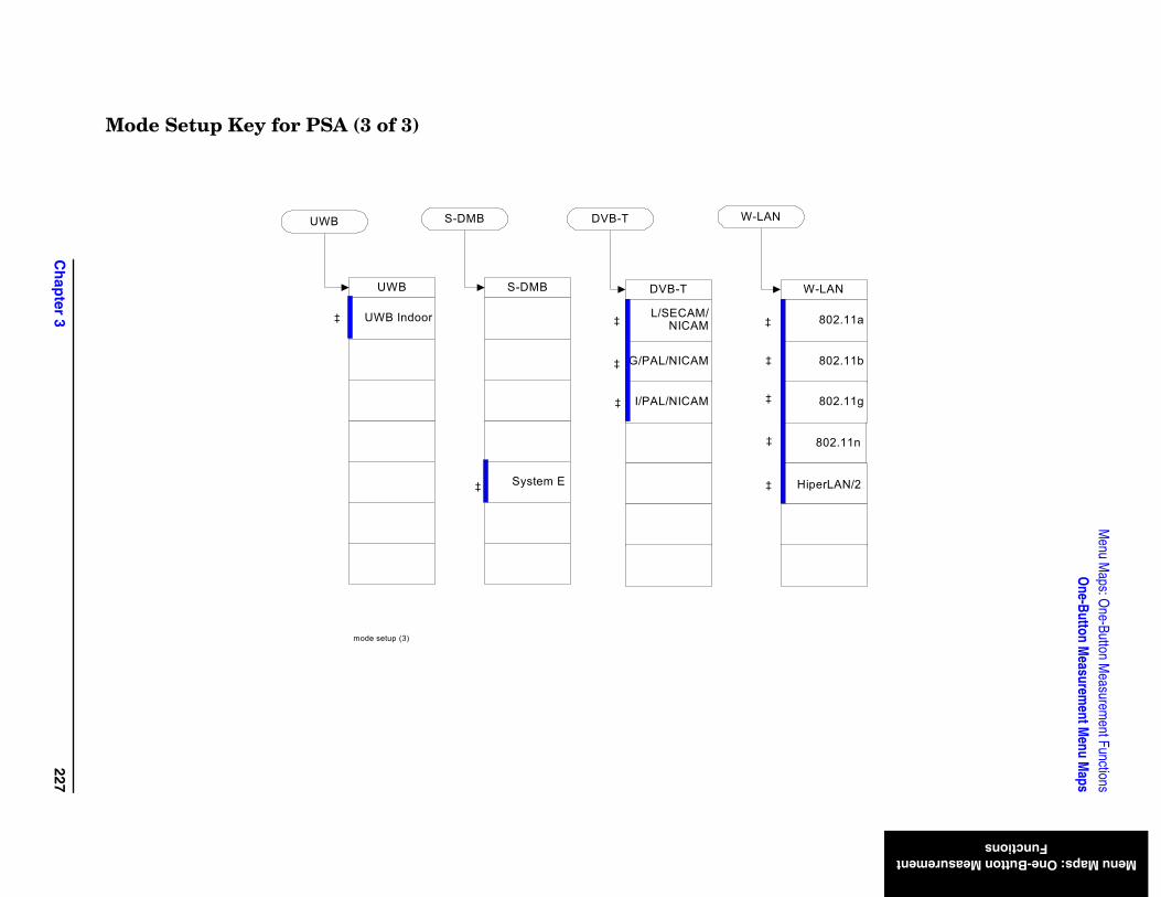
Ch
apter 3
227
Menu M
aps: One-Button M
easurement Functions
One-Button M
easurement M
enu Maps
Menu Maps: One-Button Measurement Functions
802.11n
iperLAN/2
-LAN
802.11a
802.11b
802.11g
Mode Setup Key for PSA (3 of 3)
H
WDVB-T
L/SECAM/NICAM
G/PAL/NICAM
I/PAL/NICAM
System E
S-DMBUWB
UWB Indoor
mode setup (3)
‡
‡
‡
‡
‡
‡
‡
‡
‡
UWB S-DMB DVB-T W-LAN
‡
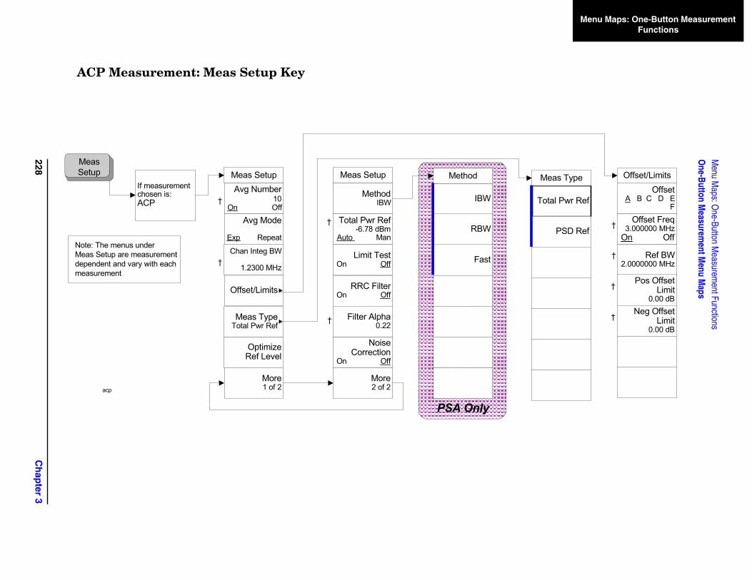
228C
hap
ter 3
Menu M
aps: One-Button M
easurement Functions
One-Button M
easurement M
enu Maps
Menu Maps: One-Button Measurement Functions
Total Pwr Ref
PSD Ref
Meas TypeOffset
A B C D E F
Offset Freq3.000000 MHz
On Off
Ref BW2.0000000 MHz
†
Pos Offset Limit
0.00 dB†
Neg Offset Limit
0.00 dB†
Offset/Limits
†
ACP Measurement: Meas Setup Key
If measurement chosen is:ACP
Meas Setup
Optimize Ref Level
Avg Number10
On Off
Chan Integ BW
1.2300 MHz
Avg Mode
Exp Repeat
Meas Setup
Method IBW
Total Pwr Ref-6.78 dBm
Auto Man
More1 of 2
More2 of 2
Meas TypeTotal Pwr Ref
Offset/Limits
†
†
†
Limit TestOn Off
RRC FilterOn Off
Noise Correction
On Off
Meas Setup
Filter Alpha0.22
†
Note: The menus underMeas Setup are measurementdependent and vary with each measurement
acp
IBW
RBW
Method
Fast
PSA Only
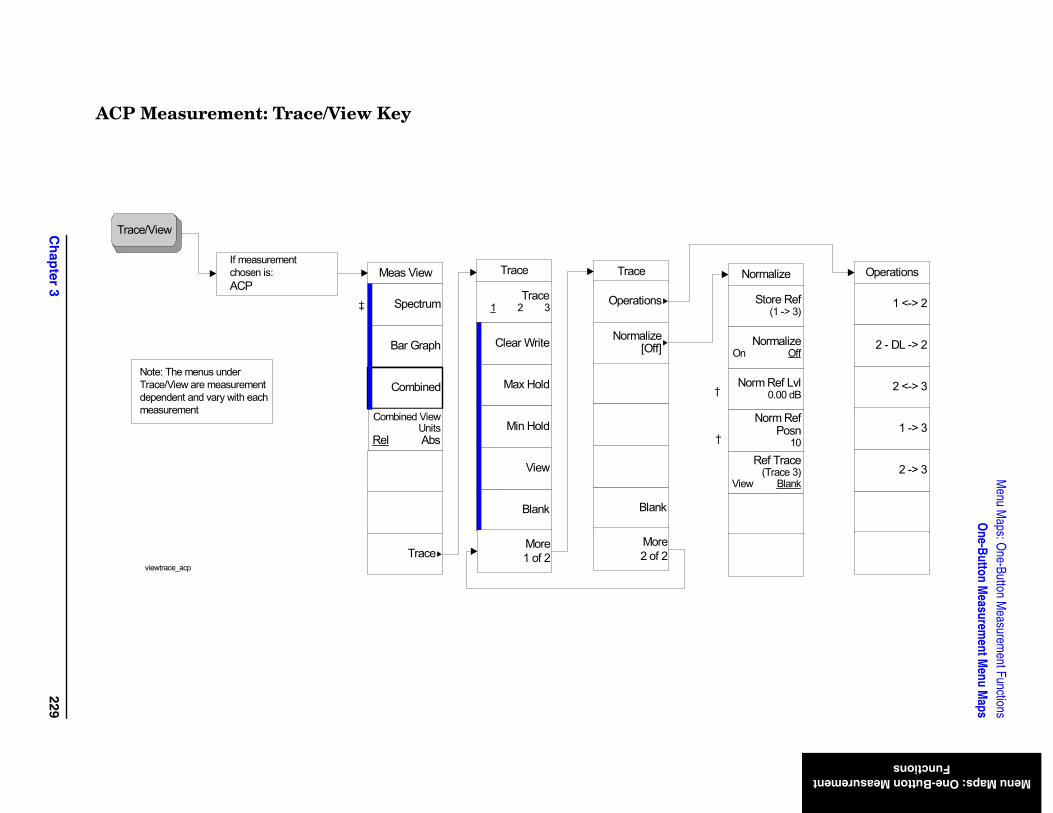
Ch
apter 3
229
Menu M
aps: One-Button M
easurement Functions
One-Button M
easurement M
enu Maps
Menu Maps: One-Button Measurement Functions
Operations
2 -> 3
2 <-> 3
1 -> 3
1 <-> 2
2 - DL -> 2
Normalize
Ref Trace(Trace 3)
View Blank
Norm Ref Lvl0.00 dB
Norm Ref Posn
10
Store Ref(1 -> 3)
NormalizeOn Off
ACP Measurement: Trace/View Key
Trace/View
Note: The menus underTrace/View are measurementdependent and vary with each measurement
Meas View
Bar Graph
Spectrum
Combined
Combined ViewUnits
Rel Abs
If measurementchosen is:ACP
Traceviewtrace_acp
‡
Trace
Blank
View
Max Hold
Min Hold
Trace1 2 3
Clear Write
More1 of 2
Trace
Blank
More2 of 2
Operations
Normalize[Off]
†
†
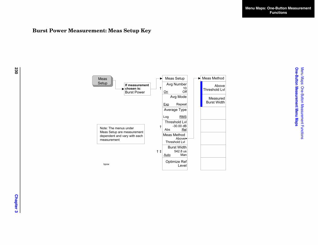
230C
hap
ter 3
Menu M
aps: One-Button M
easurement Functions
One-Button M
easurement M
enu Maps
Menu Maps: One-Button Measurement Functions
thod
bove d Lvl
ured idth
Burst Power Measurement: Meas Setup Key
If measurement chosen is:Burst Power
Meas Setup
Optimize Ref Level
Avg Number10
On Off
Threshold Lvl-30.00 dB
Abs Rel
Avg Mode
Exp Repeat
Average Type
Log RMS
Burst Width542.8 us
Auto Man
Meas MethodAbove
Threshold Lvl
Meas Me
AThreshol
MeasBurst W
Meas Setup
Note: The menus underMeas Setup are measurementdependent and vary with each measurement
bpow
†
†
‡†
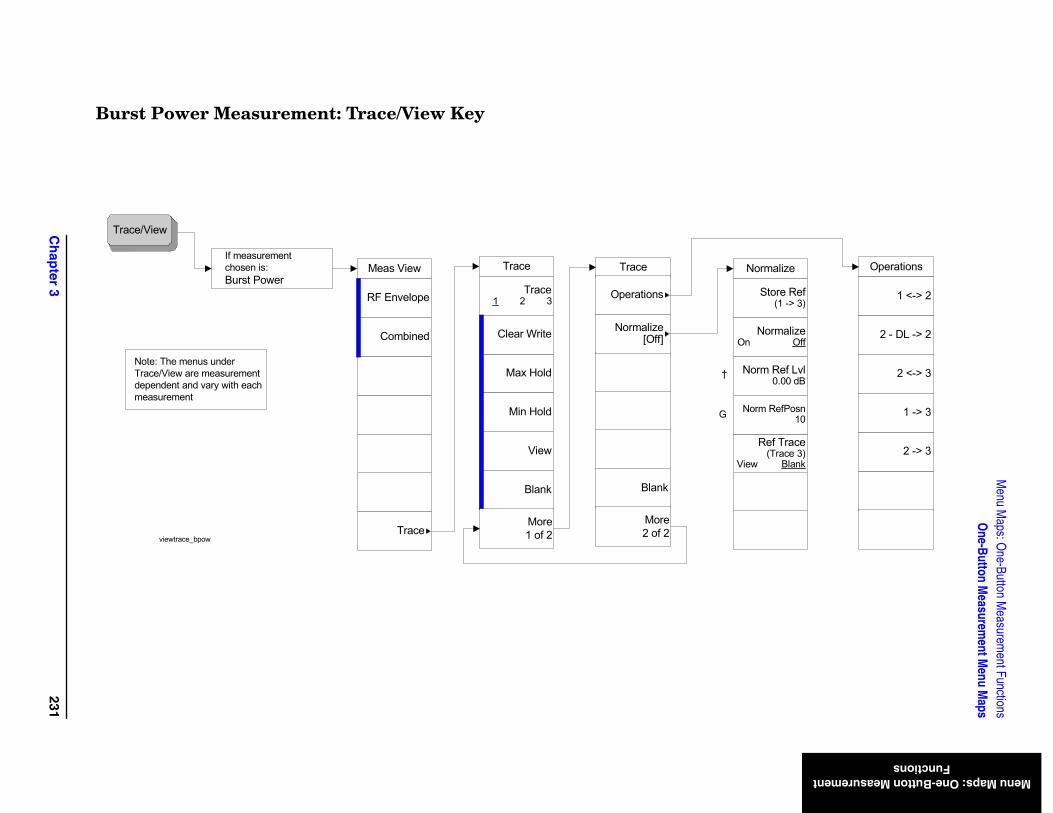
Ch
apter 3
231
Menu M
aps: One-Button M
easurement Functions
One-Button M
easurement M
enu Maps
Menu Maps: One-Button Measurement Functions
Operations
2 -> 3
2 <-> 3
1 -> 3
1 <-> 2
2 - DL -> 2
Normalize
Ref Trace(Trace 3)
View Blank
Norm Ref Lvl0.00 dB
Norm RefPosn10
Store Ref(1 -> 3)
NormalizeOn Off
Burst Power Measurement: Trace/View Key
Trace/View
Note: The menus underTrace/View are measurementdependent and vary with each measurement
If measurementchosen is:Burst Power
Meas View
Combined
RF Envelope
Traceviewtrace_bpow
Trace
Blank
View
Max Hold
Min Hold
Trace1 2 3
Clear Write
More1 of 2
Trace
Blank
More2 of 2
Operations
Normalize[Off]
†
G

232C
hap
ter 3
Menu M
aps: One-Button M
easurement Functions
One-Button M
easurement M
enu Maps
Menu Maps: One-Button Measurement Functions
CCDF (Power Stat) Measurement: Meas Setup Key
Meas BW5.0 MHz
Counts100.0 kpts
Meas Interval1.00 ms
Optimize Ref Level
Meas Setup
If measurement chosen is:Power Stat CCDF
Meas Setup
Note: The menus underMeas Setup are measurementdependent and vary with each measurement
ccdf
†
†
†
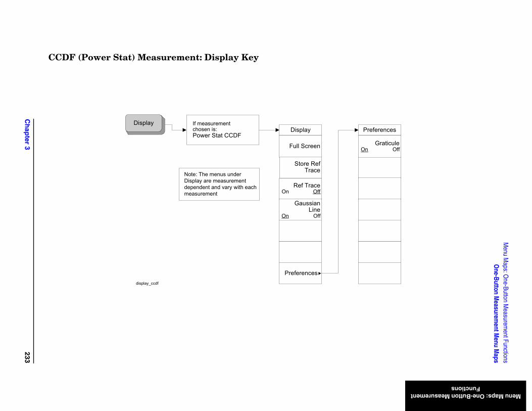
Ch
apter 3
233
Menu M
aps: One-Button M
easurement Functions
One-Button M
easurement M
enu Maps
Menu Maps: One-Button Measurement Functions
eferences
Graticule Off
CCDF (Power Stat) Measurement: Display Key
DisplayDisplay
Ref TraceOn Off
Preferences
Full Screen
If measurement chosen is:Power Stat CCDF
Note: The menus underDisplay are measurementdependent and vary with each measurement
Pr
On
Gaussian Line
On Off
Store Ref Trace
display_ccdf
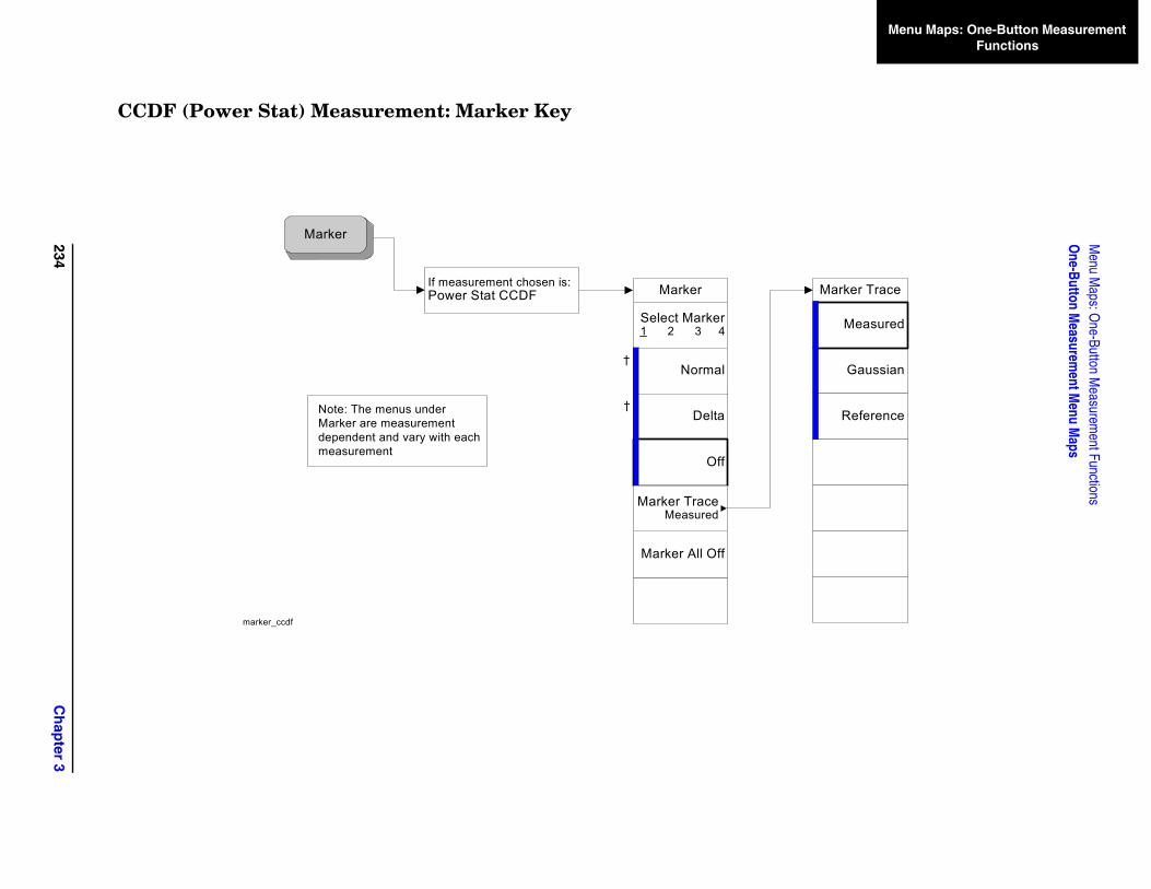
234C
hap
ter 3
Menu M
aps: One-Button M
easurement Functions
One-Button M
easurement M
enu Maps
Menu Maps: One-Button Measurement Functions
Marker Trace
Gaussian
Reference
Measured
CCDF (Power Stat) Measurement: Marker Key
Marker
†
†
Marker All Off
Marker
Delta
Select Marker1 2 3 4
Normal
Off
marker_ccdf
Note: The menus underMarker are measurementdependent and vary with each measurement
Marker TraceMeasured
If measurement chosen is:Power Stat CCDF
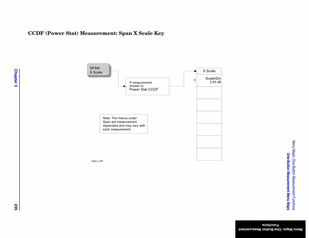
Ch
apter 3
235
Menu M
aps: One-Button M
easurement Functions
One-Button M
easurement M
enu Maps
Menu Maps: One-Button Measurement Functions
/Div0 dB
CCDF (Power Stat) Measurement: Span X Scale Key
X Scale
Scale2.0
SPANX Scale
Note: The menus underSpan are measurementdependent and may vary with each measurement
If measurement chosen is:Power Stat CCDF
span_ccdf
†
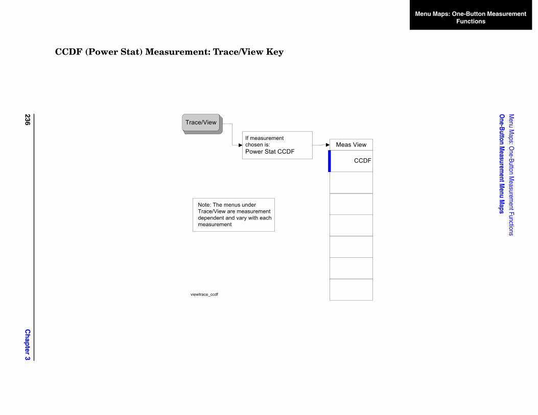
236C
hap
ter 3
Menu M
aps: One-Button M
easurement Functions
One-Button M
easurement M
enu Maps
Menu Maps: One-Button Measurement Functions
F
CCDF (Power Stat) Measurement: Trace/View Key
Trace/View
Note: The menus underTrace/View are measurementdependent and vary with each measurement
If measurementchosen is:Power Stat CCDF
Meas View
CCD
viewtrace_ccdf
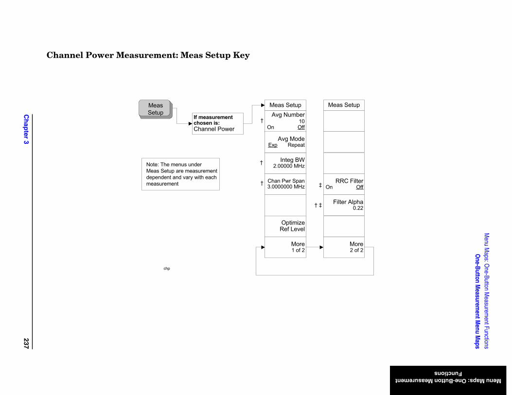
Ch
apter 3
237
Menu M
aps: One-Button M
easurement Functions
One-Button M
easurement M
enu Maps
Menu Maps: One-Button Measurement Functions
p
ref 2
terOff
ha.22
Channel Power Measurement: Meas Setup Key
If measurement chosen is:Channel Power
Meas SetupAvg Number
10On Off
Chan Pwr Span3.0000000 MHz
Integ BW2.00000 MHz
Avg ModeExp Repeat
Meas Setup
Optimize Ref Level
Meas Setu
Mo2 o
RRC FilOn
Filter Alp0
More1 of 2
Note: The menus underMeas Setup are measurementdependent and vary with each measurement
chp
†
†
†
†
‡
‡
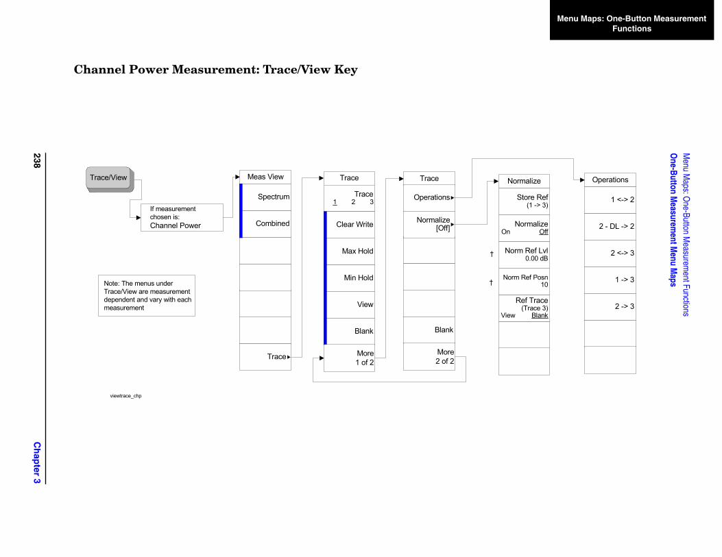
238C
hap
ter 3
Menu M
aps: One-Button M
easurement Functions
One-Button M
easurement M
enu Maps
Menu Maps: One-Button Measurement Functions
Operations
2 -> 3
2 <-> 3
1 -> 3
1 <-> 2
2 - DL -> 2
Normalize
Ref Trace(Trace 3)
View Blank
Norm Ref Lvl0.00 dB
Norm Ref Posn10
Store Ref(1 -> 3)
NormalizeOn Off
Channel Power Measurement: Trace/View Key
Trace/View
If measurementchosen is:Channel Power
Meas View
Combined
Spectrum
Trace
Blank
View
Max Hold
Min Hold
Trace1 2 3
Clear Write
Note: The menus underTrace/View are measurementdependent and vary with each measurement
Trace
viewtrace_chp
More1 of 2
Trace
Blank
More2 of 2
Operations
Normalize[Off]
†
†
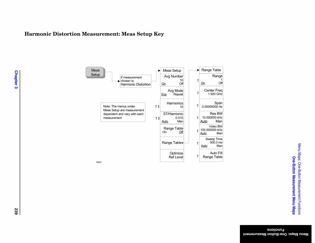
Ch
apter 3
239
Menu M
aps: One-Button M
easurement Functions
One-Button M
easurement M
enu Maps
Menu Maps: One-Button Measurement Functions
H
eqHz
WHz an
es
an
e
illle
ge1
Off
anHz
WHz an
armonic Distortion Measurement: Meas Setup Key
Meas Setup
Optimize Ref Level
Avg Number10
On Off
Harmonics10
ST/Harmonic0.015
Auto Man
If measurement chosen is:Harmonic Distortion
Avg ModeExp Repeat
Meas Setup
Range TableOn Off
Range Table
Center Fr1.920 G
Video B100.000000 kAuto M
Sweep Tim500.0 m
Auto M
Range Tabl
Auto F Range Tab
Note: The menus underMeas Setup are measurementdependent and vary with each measurement
Ran
On
Sp0.00000000
Res B10.000000 k
Auto M
harm
‡
‡
†
†
†
†
†
†
†
†
†
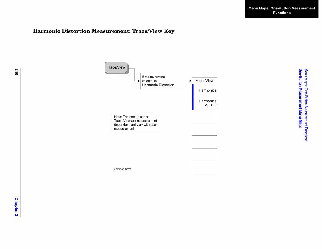
240C
hap
ter 3
Menu M
aps: One-Button M
easurement Functions
One-Button M
easurement M
enu Maps
Menu Maps: One-Button Measurement Functions
Harmonic Distortion Measurement: Trace/View Key
Trace/View
Note: The menus underTrace/View are measurementdependent and vary with each measurement
If measurementchosen is:Harmonic Distortion
Meas View
Harmonics & THD
Harmonics
viewtrace_harm
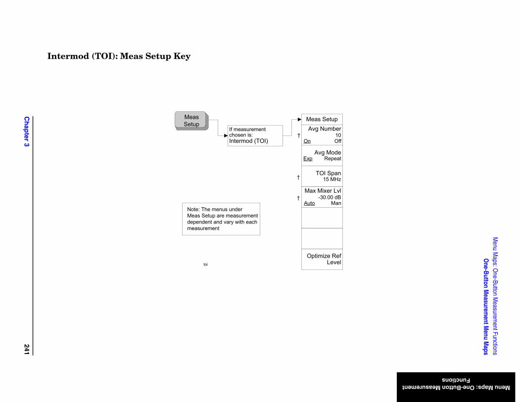
Ch
apter 3
241
Menu M
aps: One-Button M
easurement Functions
One-Button M
easurement M
enu Maps
Menu Maps: One-Button Measurement Functions
Intermod (TOI): Meas Setup Key
Meas Setup
Optimize Ref Level
Avg Number10
On Off
TOI Span15 MHz
Max Mixer Lvl-30.00 dB
Auto Man
Avg ModeExp Repeat
Meas Setup
If measurement chosen is:Intermod (TOI)
Note: The menus underMeas Setup are measurementdependent and vary with each measurement
toi
†
†
†
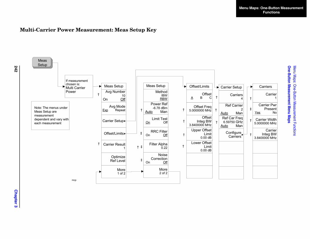
242C
hap
ter 3
Menu M
aps: One-Button M
easurement Functions
One-Button M
easurement M
enu Maps
Menu Maps: One-Button Measurement Functions
M
Carrier Setup
Carriers4
Ref Carrier2
Auto ManRef Car Freq6.59750 GHz
Auto Man
Configure Carriers
Carriers
Carrier1
Carrier Pwr Present
Yes No
Carrier Width5.0000000 MHz
Carrier Integ BW
3.8400000 MHz
†
†
†
†
‡
†
†
ulti-Carrier Power Measurement: Meas Setup Key
MeasSetup
Meas SetupAvg Number
10On Off
Avg ModeExp Repeat
Carrier Setup
Offset/Limits
Carrier Result1
Optimize Ref Level
More1 of 2
Meas SetupMethod
IBW RBW
Power Ref-6.78 dBm
Auto Man
Limit TestOn Off
RRC FilterOn Off
Filter Alpha0.22
Noise Correction
On Off
More2 of 2
Offset/Limits
Offset Freq5.0000000 MHz
Lower OffsetLimit
0.00 dB
If measurement chosen is:Multi Carrier Power
Note: The menus underMeas Setup are measurementdependent and vary with each measurement
†
†
mcp
‡
‡†
†
‡
†
†
†
†
OffsetA B C
Offset Integ BW
3.8400000 MHzUpper Offset
Limit0.00 dB

Ch
apter 3
243
Menu M
aps: One-Button M
easurement Functions
One-Button M
easurement M
enu Maps
Menu Maps: One-Button Measurement Functions
Operations
2 -> 3
2 <-> 3
1 -> 3
1 <-> 2
2 - DL -> 2
Normalize
Ref Trace(Trace 3)
View Blank
Norm Ref Lvl0.00 dB
Norm Ref Posn10
Store Ref(1 -> 3)
NormalizeOn Off
Multi-Carrier Power Measurement: Trace/View Key
Trace/View
Note: The menus underTrace/View are measurementdependent and vary with each measurement
If measurementchosen is:Multi Carrier Power
Meas View
Spectrum
Combined View Units
Rel Abs
Trace
Combined
viewtrace_mcp
Trace
Blank
View
Max Hold
Min Hold
Trace1 2 3
Clear Write
More1 of 2
Trace
Blank
More2 of 2
Operations
Normalize[Off]
†
†
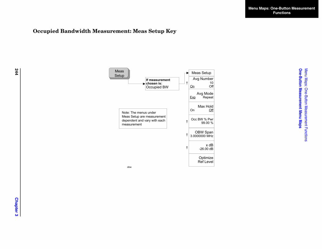
244C
hap
ter 3
Menu M
aps: One-Button M
easurement Functions
One-Button M
easurement M
enu Maps
Menu Maps: One-Button Measurement Functions
Occupied Bandwidth Measurement: Meas Setup Key
Meas Setup
OBW Span3.0000000 MHz
x dB-26.00 dB
Optimize Ref Level
Avg Number10
On Off
Occ BW % Pwr99.00 %
Max HoldOn Off
Avg ModeExp Repeat
If measurement chosen is:Occupied BW
Meas Setup
Note: The menus underMeas Setup are measurementdependent and vary with each measurement
obw
†
†
†
†
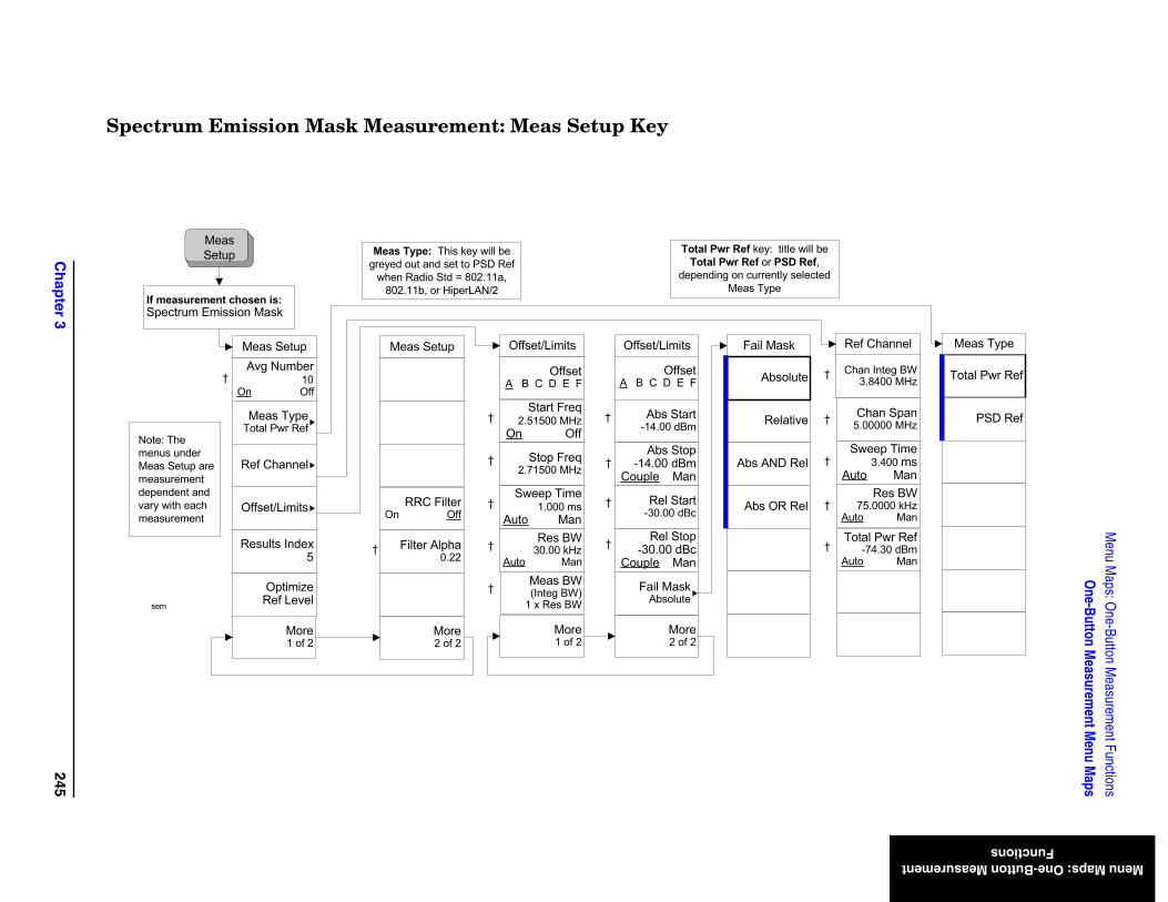
Ch
apter 3
245
Menu M
aps: One-Button M
easurement Functions
One-Button M
easurement M
enu Maps
Menu Maps: One-Button Measurement Functions
Ref Channel
Chan Integ BW3.8400 MHz Total Pwr Ref
PSD Ref
Meas Type
Chan Span5.00000 MHz
†
Sweep Time3.400 ms
Auto ManRes BW
75.0000 kHzAuto Man
†
†
†
†
l be f, cted
Total Pwr Ref-74.30 dBm
Auto Man
Spectrum Emission Mask Measurement: Meas Setup Key
Meas Setup
If measurement chosen is:Spectrum Emission Mask
Meas Setup
Optimize Ref Level
Avg Number10
On Off
More1 of 2
More2 of 2
Meas TypeTotal Pwr Ref
Offset/Limits
OffsetA B C D E F
Start Freq2.51500 MHz
On Off
† Stop Freq2.71500 MHz
†
†
†
Offset/Limits
†
Sweep Time1.000 ms
Auto ManRes BW
30.00 kHzAuto Man
OffsetA B C D E F
Abs Start-14.00 dBm
†
†
†
Offset/Limits
†
Abs Stop-14.00 dBm
Couple Man
Rel Start-30.00 dBc
Rel Stop-30.00 dBc
Couple Man
Relative
Abs AND Rel
Abs OR Rel
Fail Mask
Fail MaskAbsolute
Absolute
Results Index5
Ref Channel
† Meas BW(Integ BW)
1 x Res BW
Meas Setup
More2 of 2
RRC FilterOn Off
Filter Alpha0.22
†
More1 of 2
Note: The menus underMeas Setup are measurementdependent and vary with each measurement
sem
Meas Type: This key will be greyed out and set to PSD Ref
when Radio Std = 802.11a, 802.11b, or HiperLAN/2
Total Pwr Ref key: title wilTotal Pwr Ref or PSD Re
depending on currently seleMeas Type
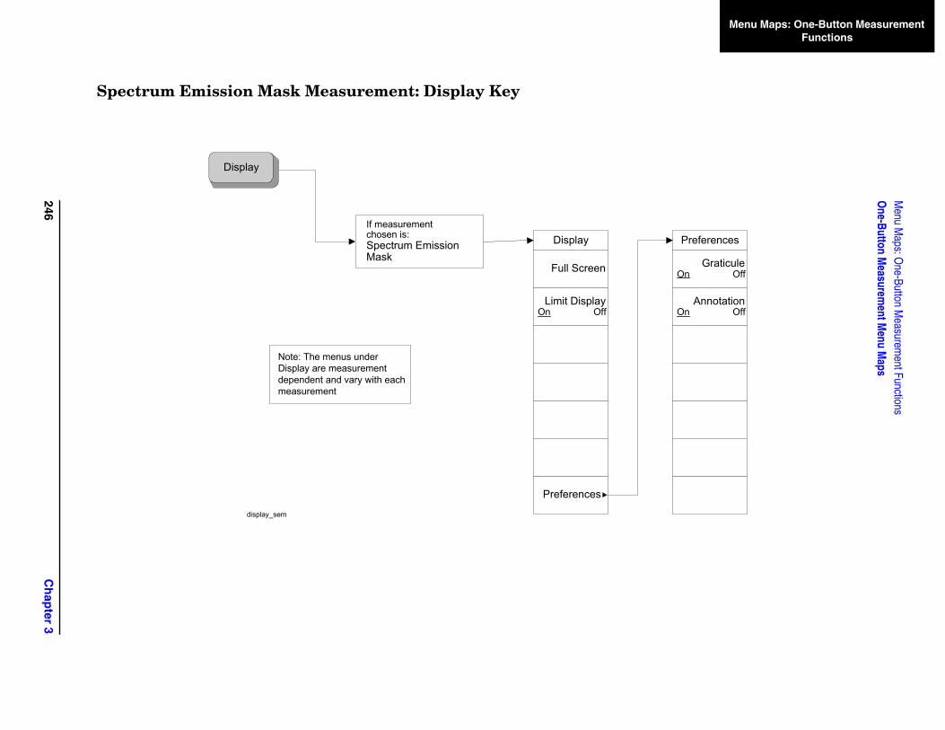
246C
hap
ter 3
Menu M
aps: One-Button M
easurement Functions
One-Button M
easurement M
enu Maps
Menu Maps: One-Button Measurement Functions
Preferences
AnnotationOn Off
GraticuleOn Off
Spectrum Emission Mask Measurement: Display Key
Display
Display
Limit DisplayOn Off
Preferences
Full Screen
If measurement chosen is:Spectrum Emission Mask
Note: The menus underDisplay are measurementdependent and vary with each measurement
display_sem
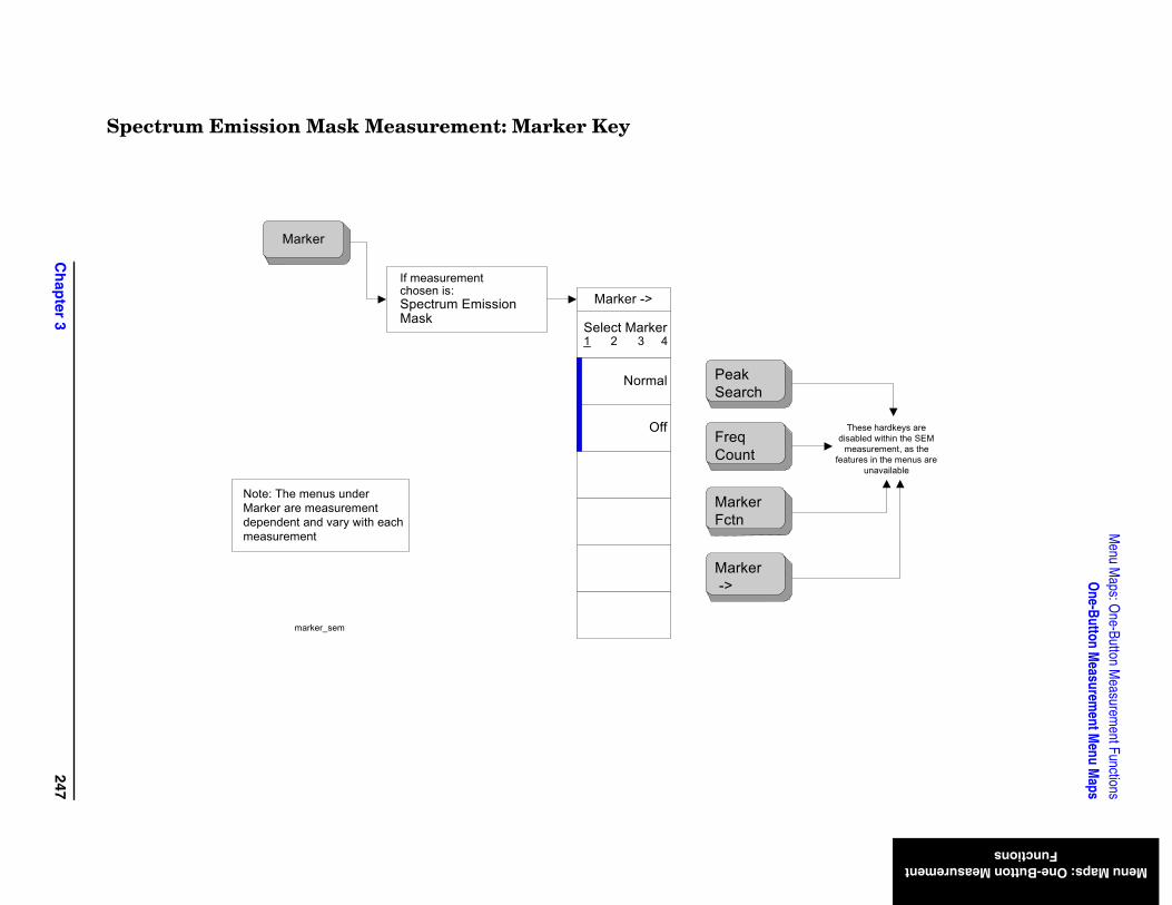
Ch
apter 3
247
Menu M
aps: One-Button M
easurement Functions
One-Button M
easurement M
enu Maps
Menu Maps: One-Button Measurement Functions
These hardkeys are disabled within the SEM
measurement, as the features in the menus are
unavailable
Spectrum Emission Mask Measurement: Marker Key
Select Marker1 2 3 4
Off
Normal
Marker
Marker ->If measurement chosen is:Spectrum Emission Mask
Note: The menus underMarker are measurementdependent and vary with each measurement
Peak Search
FreqCount
Marker Fctn
Marker ->
marker_sem
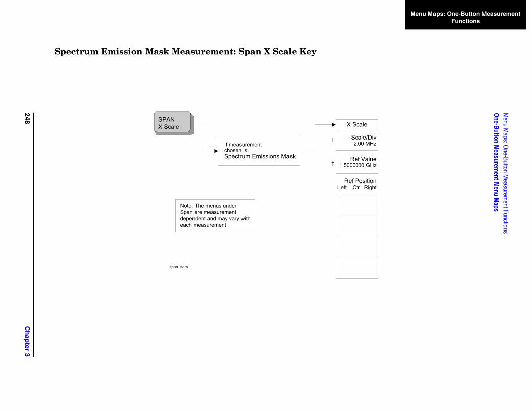
248C
hap
ter 3
Menu M
aps: One-Button M
easurement Functions
One-Button M
easurement M
enu Maps
Menu Maps: One-Button Measurement Functions
e
/Div MHz
alue GHz
itionRight
Spectrum Emission Mask Measurement: Span X Scale Key
X Scal
Scale2.00
SPANX Scale
Note: The menus underSpan are measurementdependent and may vary with each measurement
If measurement chosen is:Spectrum Emissions Mask Ref V
1.5000000
Ref PosLeft Ctr
span_sem
†
†
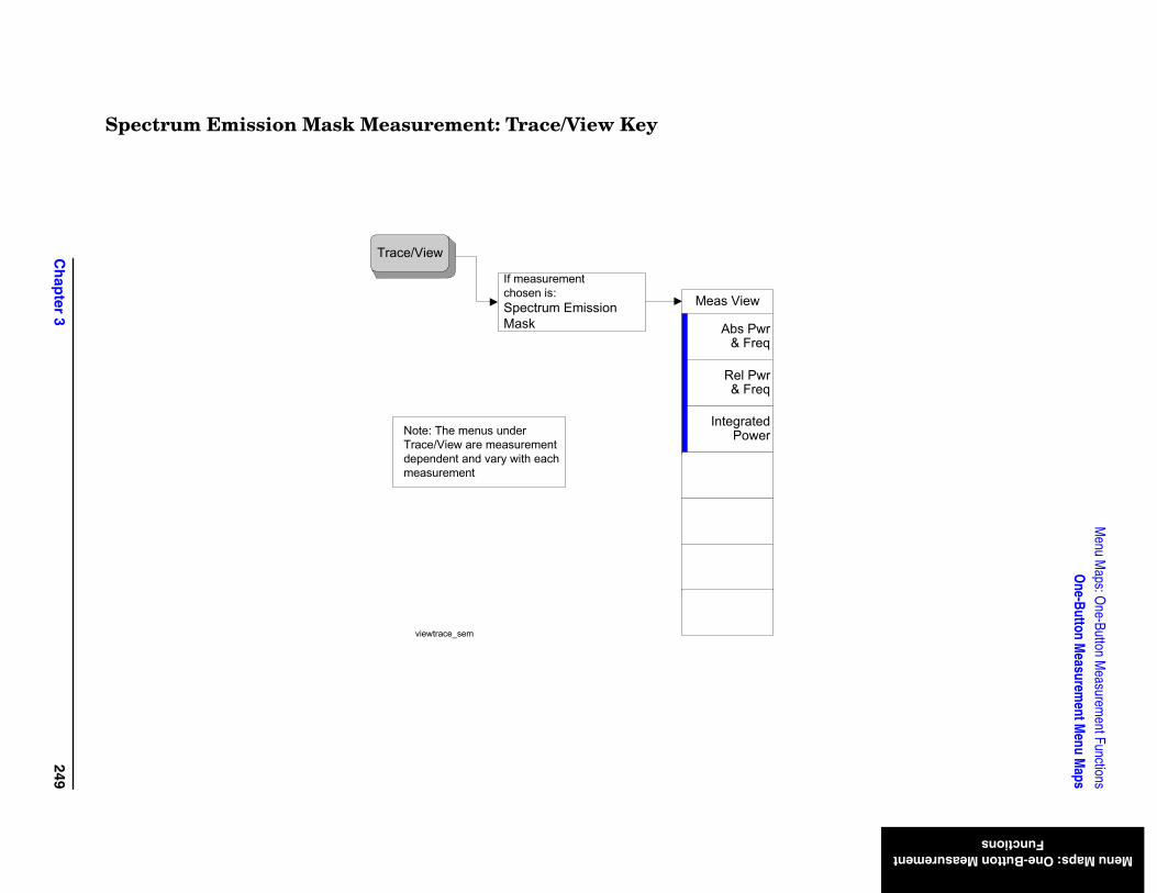
Ch
apter 3
249
Menu M
aps: One-Button M
easurement Functions
One-Button M
easurement M
enu Maps
Menu Maps: One-Button Measurement Functions
Spectrum Emission Mask Measurement: Trace/View Key
Trace/View
Note: The menus underTrace/View are measurementdependent and vary with each measurement
If measurementchosen is:Spectrum Emission Mask
Meas View
Rel Pwr& Freq
Abs Pwr & Freq
Integrated Power
viewtrace_sem
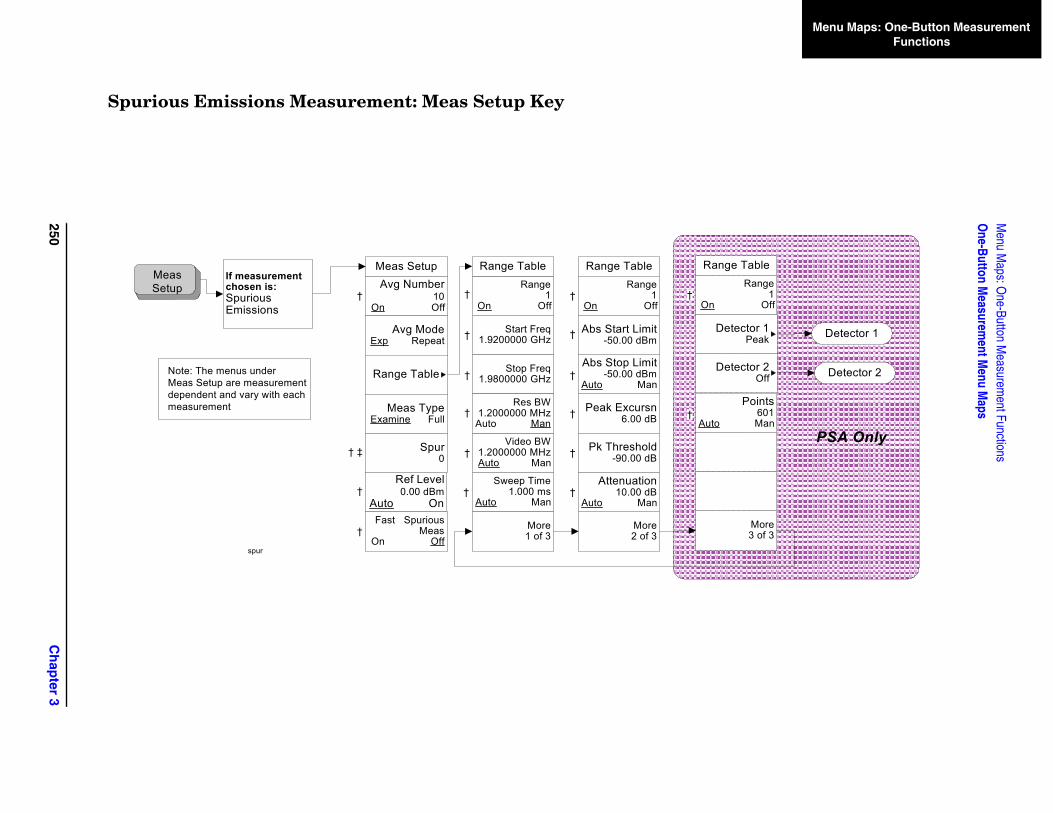
250C
hap
ter 3
Menu M
aps: One-Button M
easurement Functions
One-Button M
easurement M
enu Maps
Menu Maps: One-Button Measurement Functions
More3 of 3
ge TableRange
1 Off
Points601
Man
etector 1Peak
etector 2Off
Detector 1
Detector 2
PSA Only
Spurious Emissions Measurement: Meas Setup Key
Meas SetupAvg Number
10On Off
Avg ModeExp Repeat
Range Table
Meas TypeExamine Full
Spur0
Ref Level0.00 dBm
Auto On
Range1
On Off
Start Freq1.9200000 GHz
Stop Freq1.9800000 GHz
Video BW1.2000000 MHz Auto Man
Res BW1.2000000 MHz
Auto Man
Sweep Time1.000 ms
Auto Man
More1 of 3
More2 of 3
Attenuation10.00 dB
Auto Man
Range Table Range TableRange
1On Off
Abs Start Limit-50.00 dBm
Peak Excursn6.00 dB
Pk Threshold-90.00 dB
Meas Setup
If measurement chosen is:Spurious Emissions
Fast Spurious Meas
On Off
Abs Stop Limit-50.00 dBm
Auto Man
Ran
On
Auto
D
D
spur
Note: The menus underMeas Setup are measurementdependent and vary with each measurement
†
†
†
†
†
†
†
†
‡†
†
†
†
†
†
†
†
†
†
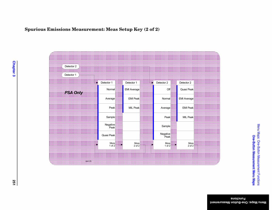
Ch
apter 3
251
Menu M
aps: One-Button M
easurement Functions
One-Button M
easurement M
enu Maps
Menu Maps: One-Button Measurement Functions
eak
eak
eak
age
2
ore of 2
Spurious Emissions Measurement: Meas Setup Key (2 of 2)
Normal
Peak
Sample
Negative Peak
Quasi Peak
Average
Detector 1
More1 of 2
EMI Average
MIL Peak
EMI Peak
Detector 1
More2 of 2
Off
Average
Peak
Sample
Negative Peak
Normal
Detector 2
More1 of 2
Quasi P
EMI P
MIL P
EMI Aver
Detector
M2
spur (2)
Detector 1
Detector 2
PSA Only
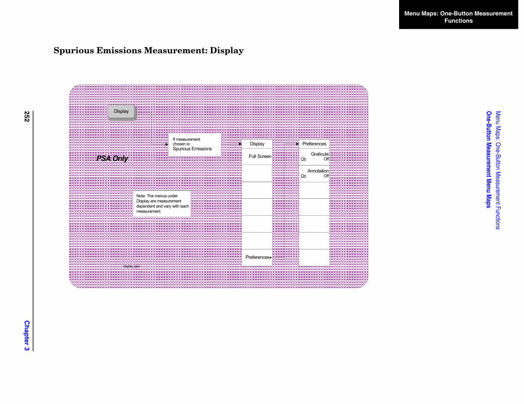
252C
hap
ter 3
Menu M
aps: One-Button M
easurement Functions
One-Button M
easurement M
enu Maps
Menu Maps: One-Button Measurement Functions
Spurious Emissions Measurement: Display
PSA Only
Display
Display
Preferences
Full Screen
If measurement chosen is:Spurious Emissions
Note: The menus underDisplay are measurementdependent and vary with each measurement
Preferences
AnnotationOn Off
GraticuleOn Off
display_spur
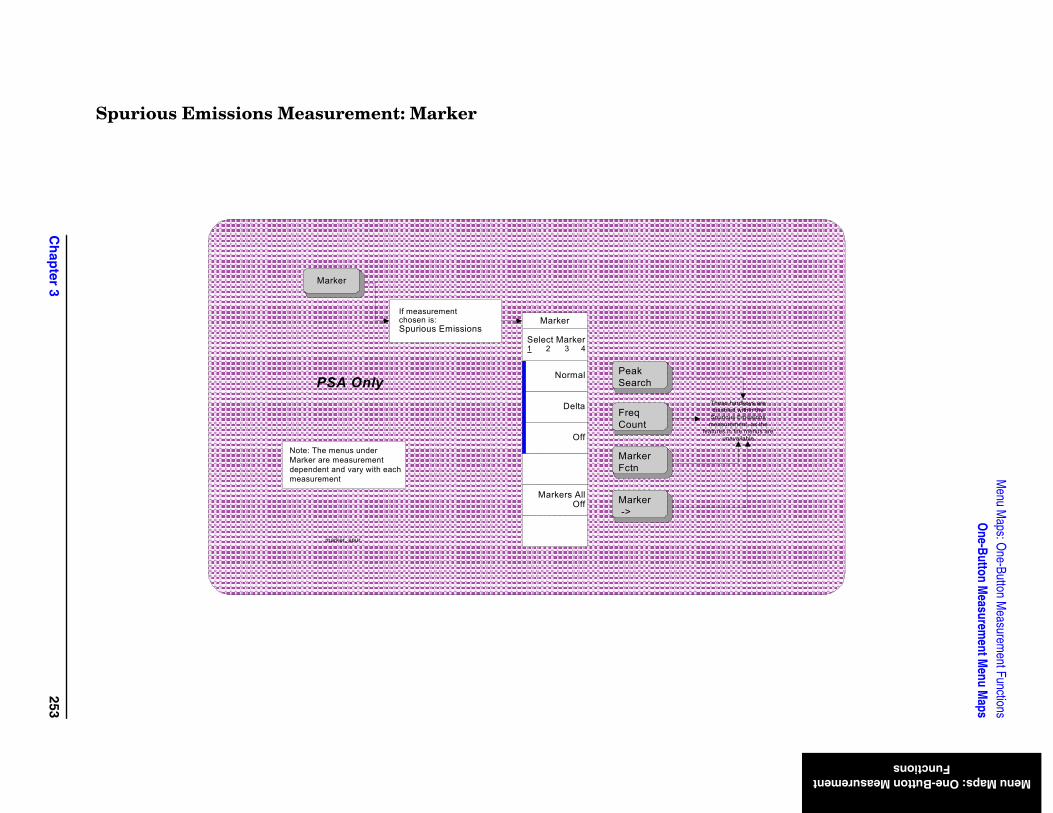
Ch
apter 3
253
Menu M
aps: One-Button M
easurement Functions
One-Button M
easurement M
enu Maps
Menu Maps: One-Button Measurement Functions
ardkeys are d within the s Emissions ment, as the the menus are vailable
Spurious Emissions Measurement: Marker
Select Marker1 2 3 4
Delta
Normal
Marker
Marker
Off
Markers All Off
If measurement chosen is:Spurious Emissions
Note: The menus underMarker are measurementdependent and vary with each measurement
Peak Search
FreqCount
Marker Fctn
Marker ->
These hdisable
Spurioumeasure
features inuna
marker_spur
PSA Only
Menu Maps: One-Button Measurement FunctionsOne-Button Measurement Menu Maps
Men
u M
aps:
On
e-B
utt
on
Mea
sure
men
t F
un
ctio
ns
254 Chapter 3
IndexIn
dex
Symbols*RST, 25
Numerics3GPP W-CDMA key, 34802.11a key, 38802.11b key, 39802.11g key, 39
Aabsolute limit, 201Absolute Limit key, 201ACP
Meas Setup menu, 228Trace/View menu, 229
ACP key, 56adjacent channel power
key, 56measurement, 56measurement setup, 81
adjacent channel power measurement
measurement setup, 99trace, 97viewing trace, 97
alpha, 123Annotation key, 188, 214attenuation
range, 203Attenuation key, 203Average key, 206, 207average mode, 82, 100, 128, 146,
195average number, 81, 121, 145,
195averaging
traces, 163, 164Avg Mode key, 82, 100, 128, 146,
164, 195Avg Number key, 81, 99, 121,
127, 141, 145, 163, 169, 195
BBand Class key, 44base station setup, 43Bluetooth key, 37book
terms, 25book, using, 25Burst Power
Meas Setup menu, 230Trace/View menu, 231
burst power measurement, trace/view, 105
BW/Avg front-panel key, 113, 114, 115, 116, 189, 215, 216, 217, 218
CCarrier IntegBW key, 152Carrier key, 150Carrier Pwr Present key, 150Carrier Result key, 156Carrier Setup key, 147Carrier Width key, 151Carriers key, 147CCDF (Power Stat)
Display menu, 233Marker menu, 234Meas Setup menu, 232SPAN X Scale menu, 235Trace/View menu, 236
CCDF measurementDisplay key, 111display settings, 111
cdma2000 SR1 key, 35cdma2000 SR3-DS key, 36cdma2000 SR3-MC key, 35Cell
band class, 44Center Freq key, 132center frequency, 132Chan Integ BW key, 82Chan Integ Bw key, 171Chan Pwr Span key, 119, 123Chan Span key, 171changing
frequency span, 193, 194Channel Power
Meas Setup menu, 237Trace/View menu, 238
Channel Power key, 52channel power measurement, 52
measurement setup, 121trace, 137viewing trace, 137
channel power span, 119, 123Combined key, 106commands
CONFigure, 50FETCh, 50MEASure, 49READ, 50, 51
complementary cumulative distribution function measurement
measurement setup, 107Configure Carriers key, 150CONFigure commands, 50Counts key, 108couplings, 25
current measurement, query, 51
Ddata acquisition sampling points,
108default values, setting remotely,
50definitions
dependencies/couplings, 25example, 25factory preset, 25maximum value, 25remote command, 25state saved, 25terms, 25
Delta key, 115, 216dependencies, 25Dependencies/Couplings term, 25Detector
1, 204, 2052, 204, 205
detectoraverage, 206, 207EMI average, 208EMI peak, 208, 209negative peak, 207normal, 206Off, 209quasi peak, 208sample, 207
Detector key, 204, 205Device BTS/MS key, 43Display front-panel key, 111, 187,
213documentation, using, 25DVB-T key, 40
EEdge Freq key, 83EDGE measurement, 34EMI Average key, 208EMI Peak key, 208, 209Enable All Measurements key, 45Example term, 25expanding
display screen, 111, 187, 213
FFactory Preset term, 25fail mask condition
absolute limit, 183absolute limit AND relative
limit, 183absolute limit OR relative limit,
183relative limit, 183
255
IndexIn
dex
Fast key, 89Fast Spurious Test key, 212fast spurious testing, 212FCC Part 15 key, 38FETCh commands, 50Filter Alpha key, 94, 125, 159,
186frequency offset, ACP, 83front-panel features (see Getting
Started guide), 25front-panel key
Display, 111, 187, 213Input/Output, 142, 143Marker, 113, 189, 215Meas Setup, 81, 99, 107, 121,
127, 141, 145, 163, 169, 195Mode Setup, 31SPAN X Scale, 119, 193Trace/View, 97, 105, 137, 139,
161, 191front-panel keys
Input/Output, 60, 62, 68, 71, 72, 73
MEASURE, 47Full Screen key, 111, 187, 213
GG/PAL/NICAM, 41gaussian trace, 112Gaussian Trace key, 112GSM/EDGE key, 34
Hhandset setup, 43Harmonic Dist key, 65Harmonic Distortion
Meas Setup menu, 239Trace/View menu, 240
harmonic distortionkey, 65measurement, 65
harmonic distortion measurementmeasurement setup, 127
harmonics key, 128Hiper LAN/2 key, 40
II/PAL/NICAM, 41IBW key, 89Input/Output front-panel key, 60,
62, 68, 71, 72, 73, 142, 143integration bandwidth, 122Integration BW key, 122IS95 key, 32, 33
JJ-STD-008 key, 33jSystem E key, 42
LL/SECAM/NICAM, 40Last Span key, 194limit line testing, 51Limit Test key, 93, 158limits
fail mask condition, 183, 184Lower Offset Limit key, 155
Mmanual, using, 25marker
X position, 117, 118Marker All Off key, 116, 217marker control mode
Delta, 115, 216Normal, 114, 190, 216
Marker front-panel key, 113, 189, 215
Marker Mode key, 218Marker Trace key, 116markers
all off, 116, 217mode, 218off, 115, 116, 190, 217selecting, 114, 116, 189, 215set mode, 218trace assignment, 116
markers off, 114, 189Max Hold key, 164Maximum Value term, 25Meas BW key, 107Meas Control
menu, 223Meas Interval key, 109Meas Off key, 52Meas Setup
ACP Measurement, 81, 99CCDF Measurement, 107Channel Power Measurement,
121Harmonic Distortion
Measurement, 127Occupied BW Measurement,
141, 163, 169, 195Meas Setup front-panel key, 81,
99, 107, 121, 127, 141, 145, 163, 169, 195
Meas Type key, 87, 170, 210MEASURE
menu, 222MEASure commands, 49
MEASURE front-panel key, 47measure setup
frequency span, 142spectrum segment
offsetoffsets and limits,
173measurement bandwidth, 107measurement reference type
power spectral density reference, 170
total power reference, 170measurement time interval, 109measurements
adjacent channel power, 56burst power, 105channel power, 52harmonic distortion, 65multi-carrier power, 145occupied bandwidth, 55query current, 51setting default values remotely,
50menu map
ACPMeas Setup key, 228Trace/View key, 229
Burst PowerMeas Setup key, 230Trace/View key, 231
CCDF (Power Stat)Display key, 233Marker key, 234Meas Setup key, 232SPAN X Scale key, 235Trace/View key, 236
Channel PowerMeas Setup key, 237Trace/View key, 238
Harmonic DistortionMeas Setup key, 239Trace/View key, 240
Meas Control, 223MEASURE, 222Mode Setup, 224, 225, 226, 227Multi-Carrier Power
Meas Setup key, 242Trace/View key, 243
Occupied BandwidthMeas Setup key, 244
Spectrum Emission MaskDisplay key, 246Marker key, 247Meas Setup key, 245SPAN X Scale key, 248Trace/View key, 249
Spurious Emissions
256
IndexIn
dex
Meas Setup key, 250, 251, 252, 253
Third Order InterceptMeas Setup key, 241
Method key, 88, 157mobile station setup, 43mode
points, 209Mode Setup
menu, 224, 225, 226, 227Mode Setup front-panel key, 31moving
trace data, 139, 191, 192multi carrier power measurement
trace, 161viewing trace, 161
Multi-Carrier PowerMeas Setup menu, 242Trace/View menu, 243
multi-carrier power measurementmeasurement setup, 145
NNADC key, 36Neg Offset Limit key, 87Negative Peak key, 207Noise Corr key, 94noise correction, 94, 160Noise Correction key, 160None key, 32Normal key, 114, 190, 206, 216
OOBW Span key, 165Occ BW % Pwr key, 165Occupied Bandwidth
Meas Setup menu, 244occupied bandwidth
measurement, 55measurement setup, 141, 163,
169, 195Occupied BW
measurement results, 56, 166Occupied BW key, 55Off key, 209Off key marker, 115, 190, 217Offset Freq key, 83, 154Offset IntegBW key, 154Offset key, 83, 153offset limit, 86, 87Offset/Limits key, 83offsets and limits
limitsabsolute start level, 180
Offsets/Limits key, 153one-button measurements, turn
off, 52
optimize ref level, 46, 88, 104, 110, 124, 136, 144, 156, 167, 185
Optimize Ref Level key, 46, 88, 104, 110, 124, 136, 144, 156, 167, 185
PPacket Type key, 44, 46pass/fail test, 51PDC key, 37peak excursion, 202Peak Excursn key, 202peak threshold, 203Pk Threshold key, 203points
mode, 209Points key, 209Pos Offset Limit key, 86power spectral density, 92power stat CCDF
Gaussian line display, 112power statistics CCDF
measurement interval, 109number of sampling points, 108reference trace display, 111store reference trace, 111
Preferences key, 112, 187, 213programmer’s reference, using, 25PSD Ref key, 170, 173
QQuasi Peak key, 208
RRadio Std Setup key, 43range
attenuation, 203Range key, 129, 131, 197range table, 129, 130, 131, 196,
197Range Table key, 130, 196READ commands, 50, 51rear-panel features (see Getting
Started guide), 25Ref BW key, 85Ref Carrier Freq key, 148Ref Carrier key, 147Ref Channel key, 170Ref Level key, 211Ref Trace key, 111reference bandwidth, 85reference level, 211reference trace, 111reference trace, storing, 111Remote Command term, 25
Res BW key, 133, 172, 199resolution bandwidth, 133, 199Retain Params key, 45RF Envelope key, 105RRC filter, 186RRC Filter key, 93, 124, 159, 186RST term, 25
SSample key, 207saved
state, 25saving
trace data, 139, 191, 192S-DMB key, 41, 42, 89Select Marker key, 114, 189, 215selecting
marker pairs, 114, 189, 215markers, 114, 189, 215
Marker Trace, 116SEM measurement
Display key, 187display settings, 187trace, 139, 191viewing trace, 139, 191
Signal BW key, 43span, 132Span key, 132, 193SPAN X Scale front-panel key,
119, 193spectral density, 92spectrum analyzer
measurements, 52Spectrum Emission Mask
Display menu, 246Marker menu, 247Meas Setup menu, 245SPAN X Scale menu, 248Trace/View menu, 249
spectrum emission maskmeasure setup
measurement reference type, 170
Spur key, 211Spurious Emissions
Meas Setup menu, 250, 251, 252, 253
spurious emissions measurementDisplay key, 213display settings, 213
spurious testfast, 212
ST/Harmonic key, 129standards setup, 43Start Freq key, 198start frequency, 198state
257
IndexIn
dex
saved, 25State Saved term, 25Stop Freq key, 198stop frequency, 198Store Ref Trace key, 111sweep time, 134, 135, 200Sweep Time key, 134, 135, 171,
200
Ttable
range, 130, 196setting
range, 129, 131, 197terms
*RST, 25book, 25definition, 25dependencies/couplings, 25example, 25factory preset, 25maximum value, 25remote command, 25state saved, 25
test limits, 51testing
spurs, 212TETRA key, 38Third Order Intercept
Meas Setup menu, 241Total Pwr Ref key, 91, 158, 173Total Pwr Refl key, 170trace
saving, 139, 191, 192transfer data, 139, 191, 192
trace averaging, 163, 164trace data
moving, 139, 191, 192Trace key, 98, 106, 137, 162Trace/View front-panel key, 97,
105, 137, 139, 161, 191turn off one-button
measurements, 52turning markers off, 115, 190,
217
UUpper Offset Limit key, 155US PCS
band class, 44US/K
band class, 44user’s reference, using, 25UWB Indoor key, 42
Vvideo bandwidth, 134, 199Video BW key, 134, 199
Xx dB key, 166
258