Embed Size (px)
Citation preview
5G systems designacross services
1
John Smee, Ph.D.Senior Director, EngineeringQualcomm Technologies, Inc.
International Workshop on Emerging Technologies for 5G Wireless Cellular Networks, San DiegoDecember 10, 2015
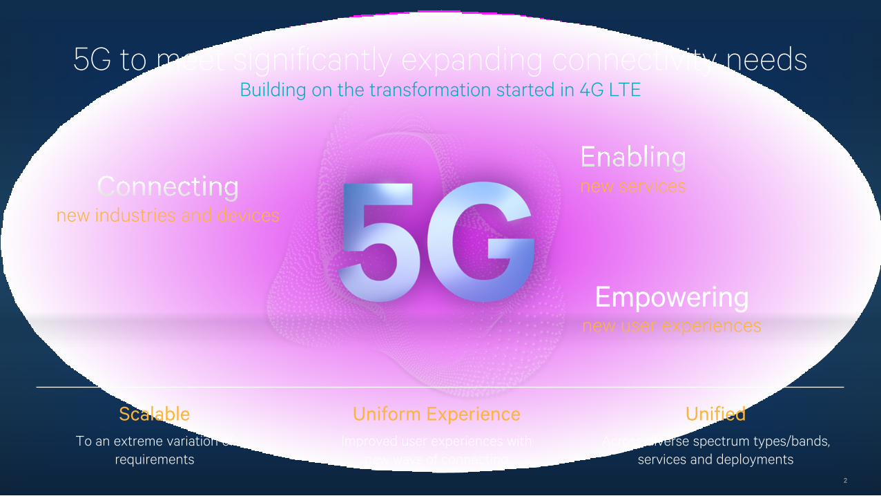
5G to meet significantly expanding connectivity needs
2
Uniform ExperienceImproved user experiences with
new ways of connecting
UnifiedAcross diverse spectrum types/bands,
services and deployments
ScalableTo an extreme variation of
requirements
Empoweringnew user experiences
new industries and devicesnew services
Building on the transformation started in 4G LTE
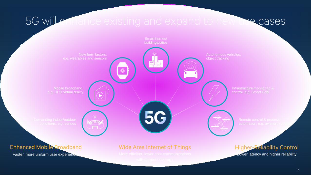
5G will enhance existing and expand to new use cases
3
Wide Area Internet of ThingsMore efficient, lower cost communications
with deeper coverage
Enhanced Mobile BroadbandFaster, more uniform user experiences
Higher-Reliability ControlLower latency and higher reliability
Smart homes/buildings/cities
Autonomous vehicles, object tracking
Remote control & process automation, e.g. aviation, robotics
Infrastructure monitoring & control, e.g. Smart Grid
Mobile broadband, e.g. UHD virtual reality
Demanding indoor/outdoor conditions, e.g. venues
New form factors, e.g. wearables and sensors
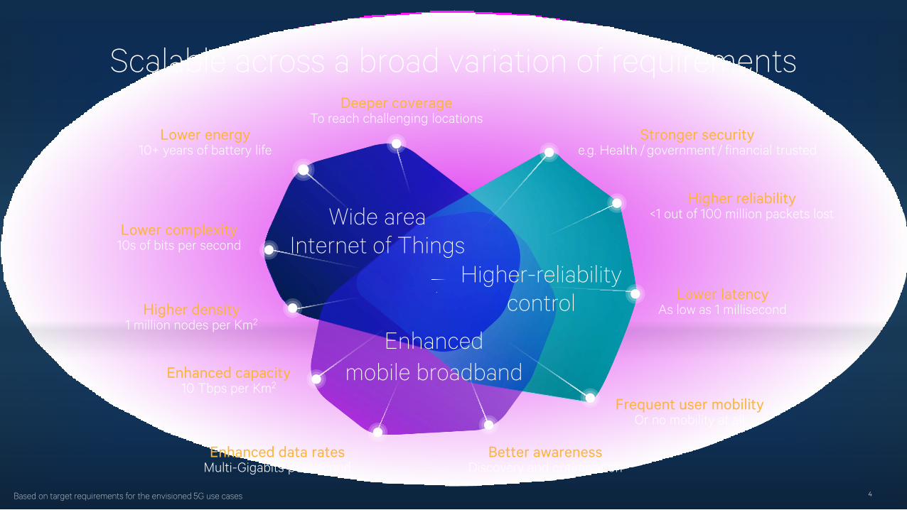
Scalable across a broad variation of requirements
4
Wide area Internet of Things
Higher-reliability control
Enhanced mobile broadband
Deeper coverageTo reach challenging locations
Lower energy10+ years of battery life
Lower complexity10s of bits per second
Higher density1 million nodes per Km2
Enhanced capacity10 Tbps per Km2
Enhanced data ratesMulti-Gigabits per second
Better awarenessDiscovery and optimization
Frequent user mobilityOr no mobility at all
Lower latencyAs low as 1 millisecond
Higher reliability<1 out of 100 million packets lost
Stronger securitye.g. Health / government / financial trusted
Based on target requirements for the envisioned 5G use cases
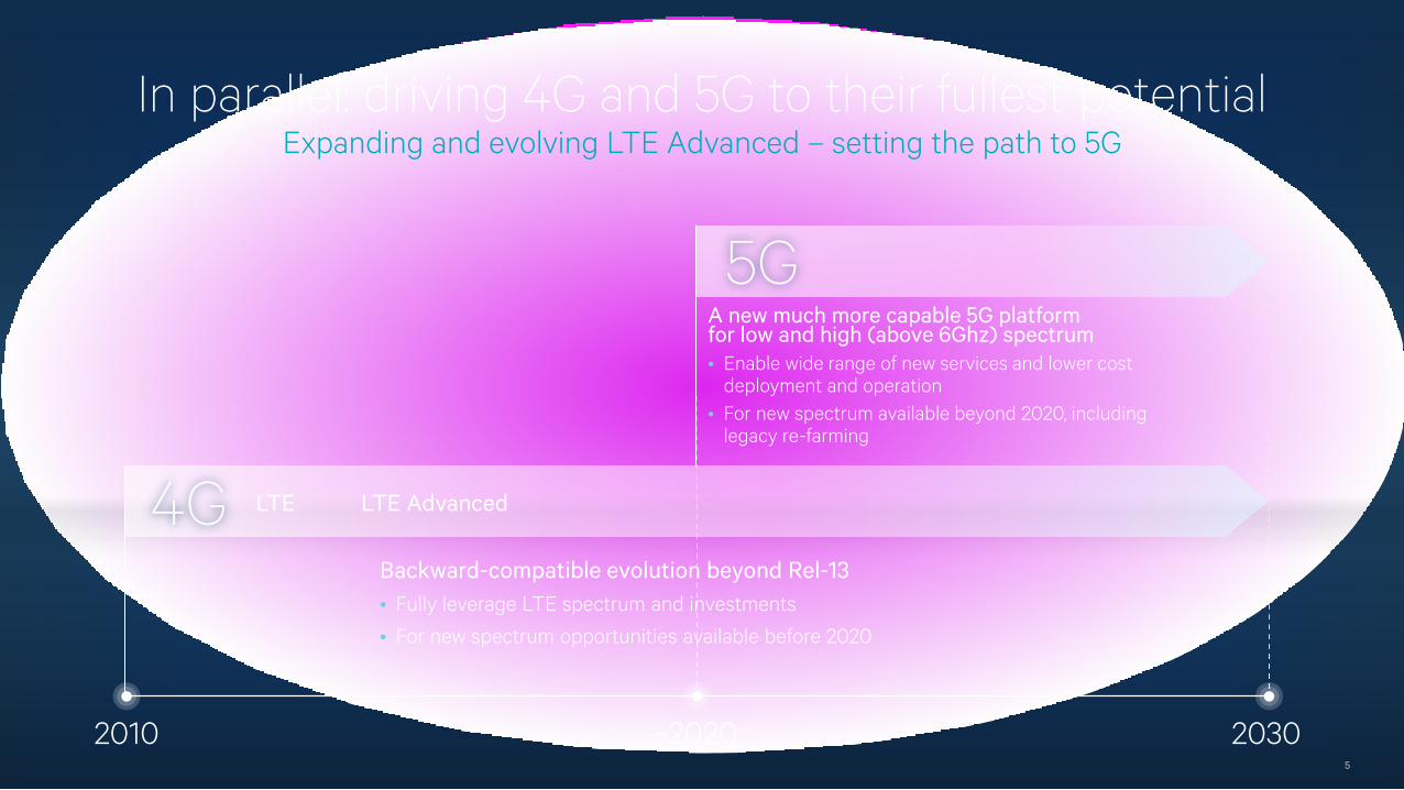
In parallel: driving 4G and 5G to their fullest potentialExpanding and evolving LTE Advanced – setting the path to 5G
5
5G
2010 ~2020 2030
4G LTE LTE Advanced
A new much more capable 5G platformfor low and high (above 6Ghz) spectrum• Enable wide range of new services and lower cost
deployment and operation• For new spectrum available beyond 2020, including
legacy re-farming
Backward-compatible evolution beyond Rel-13• Fully leverage LTE spectrum and investments
• For new spectrum opportunities available before 2020
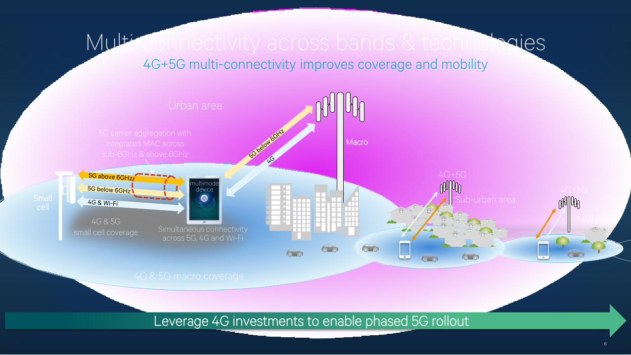
Multi-connectivity across bands & technologies4G+5G multi-connectivity improves coverage and mobility
6
Rural area
4G+5G
Sub-urban area4G+5G
Leverage 4G investments to enable phased 5G rollout
4G & 5Gsmall cell coverage
Macro5G carrier aggregation with
integrated MAC across sub-6GHz & above 6GHz
Smallcell
multimode device
Simultaneous connectivityacross 5G, 4G and Wi-Fi
Urban area
4G & 5G macro coverage
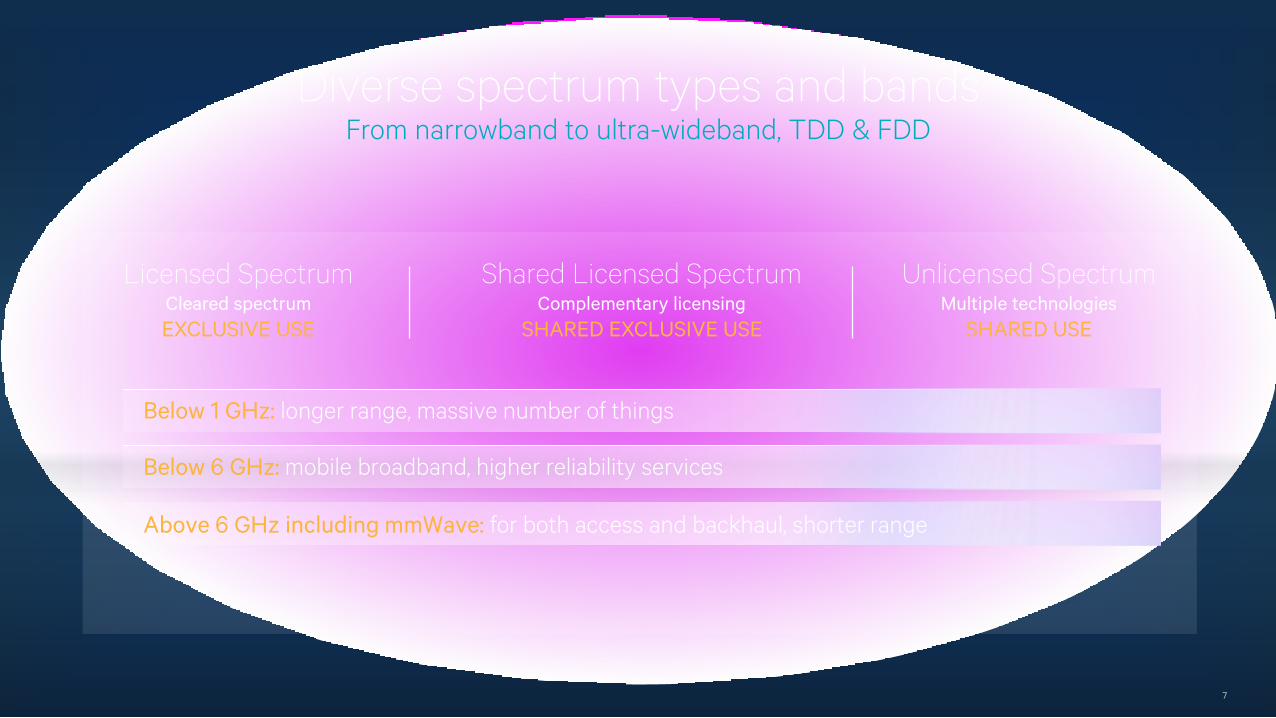
Diverse spectrum types and bandsFrom narrowband to ultra-wideband, TDD & FDD
7
Licensed SpectrumCleared spectrumEXCLUSIVE USE
Unlicensed SpectrumMultiple technologies
SHARED USE
Shared Licensed SpectrumComplementary licensing
SHARED EXCLUSIVE USE
Below 1 GHz: longer range, massive number of things
Below 6 GHz: mobile broadband, higher reliability services
Above 6 GHz including mmWave: for both access and backhaul, shorter range
A new 5G unified air interface is the foundation
8
FDD, TDD, half duplex
Licensed, shared licensed, and unlicensed spectrum
Spectrum bands below 1 GHz, 1 GHz to 6 GHz, & above 6 GHz
(incl. mmWave)
Device-to-device, mesh, relay network topologies
From wideband multi-Gbps tonarrowband 10s of bits per second
Efficient multiplexing of higher-reliability and nominal traffic
From high user mobility to no mobility at all
From wide area macro to indoor / outdoor hotspots
Diverse spectrum Diverse services and devices
Diverse deployments
Unified air interface
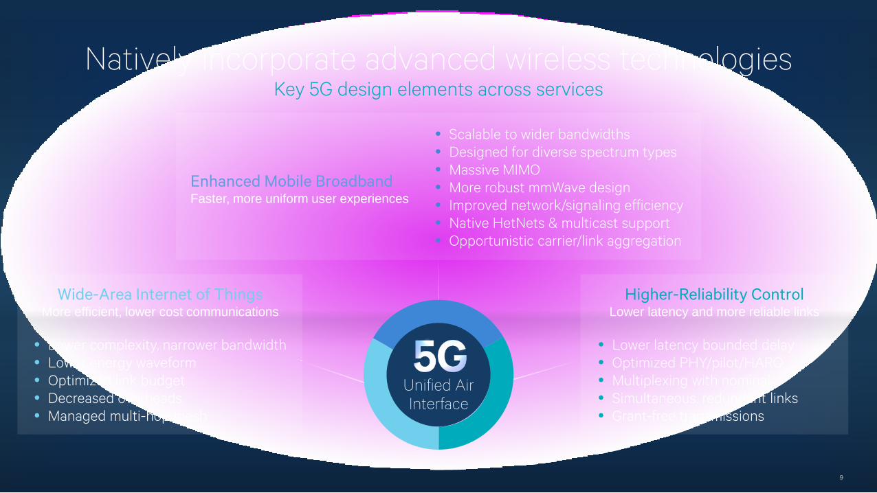
Natively incorporate advanced wireless technologiesKey 5G design elements across services
9
Wide-Area Internet of ThingsMore efficient, lower cost communications
Higher-Reliability ControlLower latency and more reliable links
Unified Air Interface
Enhanced Mobile BroadbandFaster, more uniform user experiences
• Scalable to wider bandwidths• Designed for diverse spectrum types• Massive MIMO• More robust mmWave design• Improved network/signaling efficiency• Native HetNets & multicast support• Opportunistic carrier/link aggregation
• Lower complexity, narrower bandwidth• Lower energy waveform• Optimized link budget• Decreased overheads• Managed multi-hop mesh
• Lower latency bounded delay• Optimized PHY/pilot/HARQ• Multiplexing with nominal• Simultaneous, redundant links• Grant-free transmissions
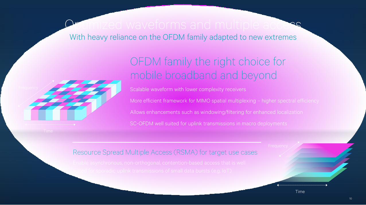
Optimized waveforms and multiple accessWith heavy reliance on the OFDM family adapted to new extremes
10
OFDM family the right choice formobile broadband and beyondScalable waveform with lower complexity receivers
More efficient framework for MIMO spatial multiplexing – higher spectral efficiency
Allows enhancements such as windowing/filtering for enhanced localization
SC-OFDM well suited for uplink transmissions in macro deployments
Resource Spread Multiple Access (RSMA) for target use casesEnable asynchronous, non-orthogonal, contention-based access that is well suited for sporadic uplink transmissions of small data bursts (e.g. IoT)
Time
Frequency
Frequency
Time
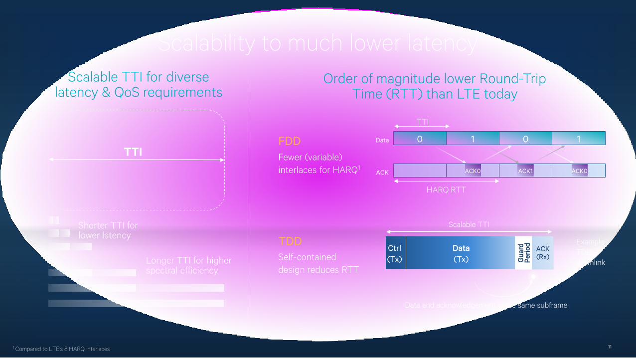
Scalability to much lower latency
11
Scalable TTI for diverse latency & QoS requirements
TTI
Longer TTI for higher spectral efficiency
Shorter TTI for lower latency
1 Compared to LTE’s 8 HARQ interlaces
Order of magnitude lower Round-Trip Time (RTT) than LTE today
0 1 0 1
ACK0
Data
ACK ACK1 ACK0
FDD
TDD
HARQ RTT
TTI
Self-contained design reduces RTT
Fewer (variable) interlaces for HARQ1
Scalable TTI
Example: TDD downlinkG
uard
Pe
riod
ACK(Rx)
Ctrl(Tx)
Data(Tx)
Data and acknowledgement in the same subframe
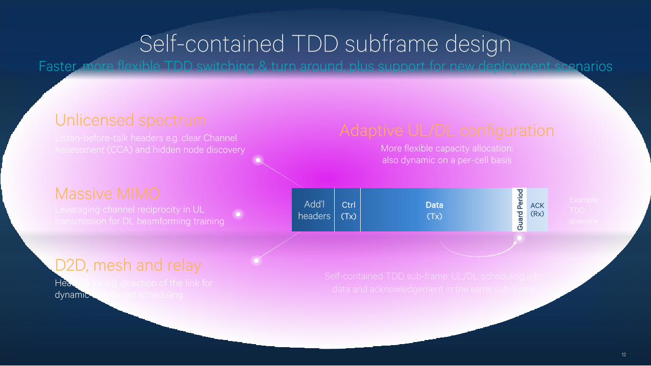
Self-contained TDD subframe designFaster, more flexible TDD switching & turn around, plus support for new deployment scenarios
12
Unlicensed spectrumListen-before-talk headers e.g. clear Channel Assessment (CCA) and hidden node discovery
Massive MIMOLeveraging channel reciprocity in UL transmission for DL beamforming training
D2D, mesh and relayHeaders for e.g. direction of the link for dynamic distributed scheduling
Self-contained TDD sub-frame: UL/DL scheduling info, data and acknowledgement in the same sub-frame
Gua
rd P
erio
d
Add’lheaders
ACK(Rx)
Ctrl(Tx)
Data(Tx)
Adaptive UL/DL configurationMore flexible capacity allocation; also dynamic on a per-cell basis
Example: TDD downlink
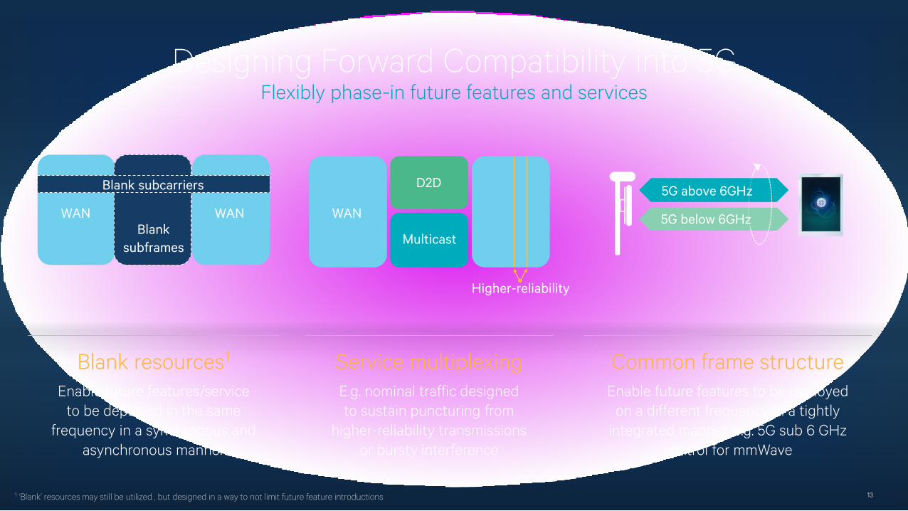
Designing Forward Compatibility into 5GFlexibly phase-in future features and services
13
Blank resources1
Enable future features/serviceto be deployed in the same
frequency in a synchronous and asynchronous manner
Service multiplexingE.g. nominal traffic designedto sustain puncturing from
higher-reliability transmissionsor bursty interference
Common frame structureEnable future features to be deployed
on a different frequency in a tightly integrated manner, e.g. 5G sub 6 GHz
control for mmWave
5G below 6GHz
5G above 6GHz
1 ‘Blank’ resources may still be utilized , but designed in a way to not limit future feature introductions
WAN
MulticastBlank
subframes
Blank subcarriers D2D
WAN WAN
Higher-reliability
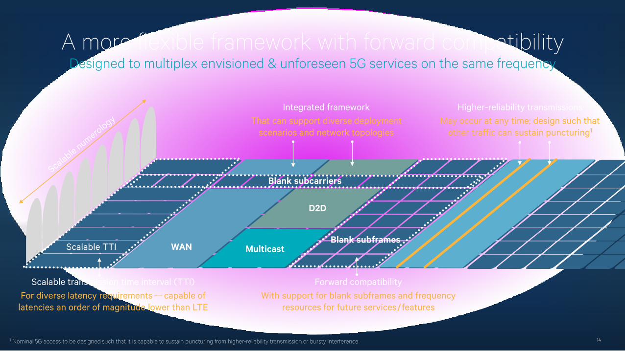
A more flexible framework with forward compatibilityDesigned to multiplex envisioned & unforeseen 5G services on the same frequency
14
Integrated frameworkThat can support diverse deployment
scenarios and network topologies
Scalable transmission time interval (TTI)For diverse latency requirements — capable of
latencies an order of magnitude lower than LTE
Higher-reliability transmissionsMay occur at any time; design such that
other traffic can sustain puncturing1
Forward compatibilityWith support for blank subframes and frequency
resources for future services/features
1 Nominal 5G access to be designed such that it is capable to sustain puncturing from higher-reliability transmission or bursty interference
Blank subcarriers
Scalable TTI WANBlank subframes
D2D
Multicast
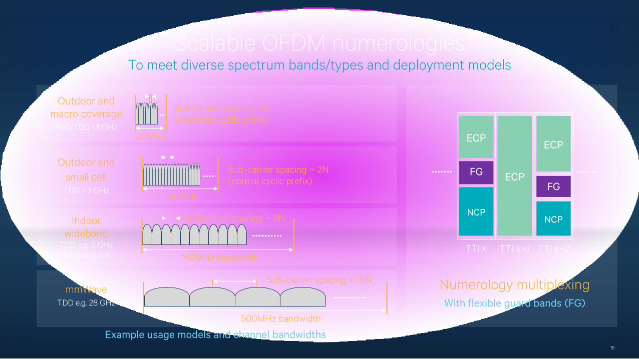
Scalable OFDM numerologies To meet diverse spectrum bands/types and deployment models
15
Sub-carrier spacing = N(extended cyclic prefix)
Outdoor andmacro coverage
FDD/TDD <3 GHz
Indoorwideband
TDD e.g. 5 GHz (Unlicensed) 160MHz bandwidth
Sub-carrier spacing = 8N
mmWaveTDD e.g. 28 GHz
Sub-carrier spacing = 2N(normal cyclic prefix)
Outdoor andsmall cell
TDD > 3 GHz80MHz
500MHz bandwidth
Sub-carrier spacing = 16N
Example usage models and channel bandwidths
20MHz
Numerology multiplexingWith flexible guard bands (FG)
ECP
FG
NCP
ECP
ECP
FG
NCP
TTI k TTI k+1 TTI k+2
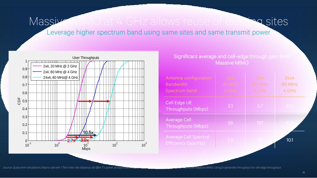
Massive MIMO at 4 GHz allows reuse of existing sitesLeverage higher spectrum band using same sites and same transmit power
16
10-1
100
101
102
103
0
0.1
0.2
0.3
0.4
0.5
0.6
0.7
0.8
0.9
1User Throughputs
Mbps
CD
F
2x4, 20 MHz @ 2 GHz 2x4, 80 MHz @ 4 GHz 24x4, 80 MHz@ 4 GHz
Source: Qualcomm simulations; Macro-cell with 1.7km inter-site distance, 46 dBm Tx power at base station,, 20MHz@2GHz and 80MHz@4GHz BW TDD, 2.4x Massive MIMO. Using 5-pertantile throughput for cell edge throughput.
Antenna configuration BandwidthSpectrum band
2x420 MHz2 GHz
2x480 MHz4 GHz
24x480 MHz4 GHz
Cell Edge UE Throughputs (Mbps)
2.1 5.7 22.1
Average Cell Throughputs (Mbps)
58 197 808
Average Cell Spectral Efficiency (bps/Hz)
2.9 2.5 10.12.7x
10.5x
Significant average and cell-edge through gain from Massive MIMO
3.9x
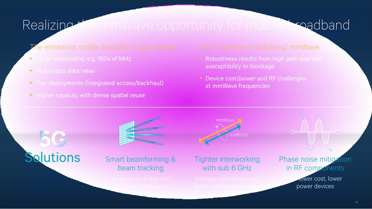
Realizing the mmWave opportunity for mobile broadband
17
Smart beamforming & beam tracking
Increase coverage and minimize interference
Solutions
mmWave
sub6Ghz
Tighter interworking with sub 6 GHz
Increase robustness and faster system acquisition
Phase noise mitigation in RF componentsFor lower cost, lower
power devices
The enhanced mobile broadband opportunity The challenge—‘mobilizing’ mmWave • Large bandwidths, e.g. 100s of MHz
• Multi-Gbps data rates
• Flex deployments (integrated access/backhaul)
• Higher capacity with dense spatial reuse
• Robustness results from high path loss and susceptibility to blockage
• Device cost/power and RF challenges at mmWave frequencies
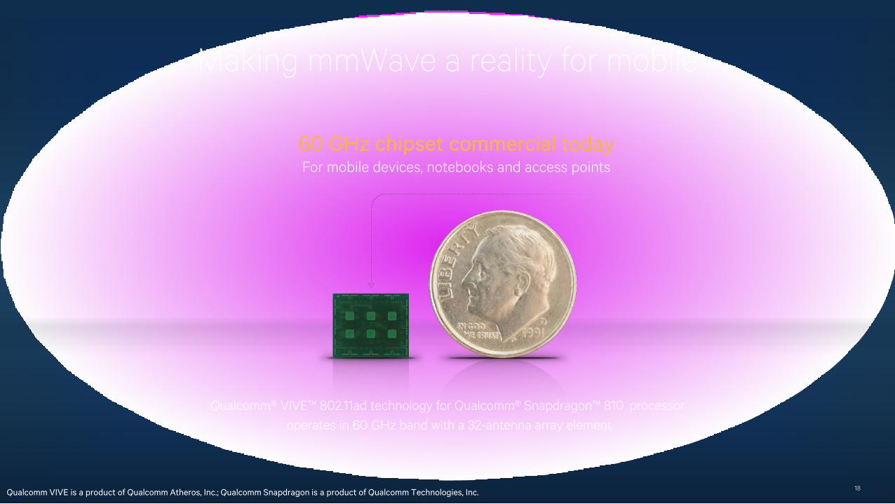
Making mmWave a reality for mobile
18
60 GHz chipset commercial todayFor mobile devices, notebooks and access points
Qualcomm® VIVE™ 802.11ad technology for Qualcomm® Snapdragon™ 810 processoroperates in 60 GHz band with a 32-antenna array element
Qualcomm VIVE is a product of Qualcomm Atheros, Inc.; Qualcomm Snapdragon is a product of Qualcomm Technologies, Inc.
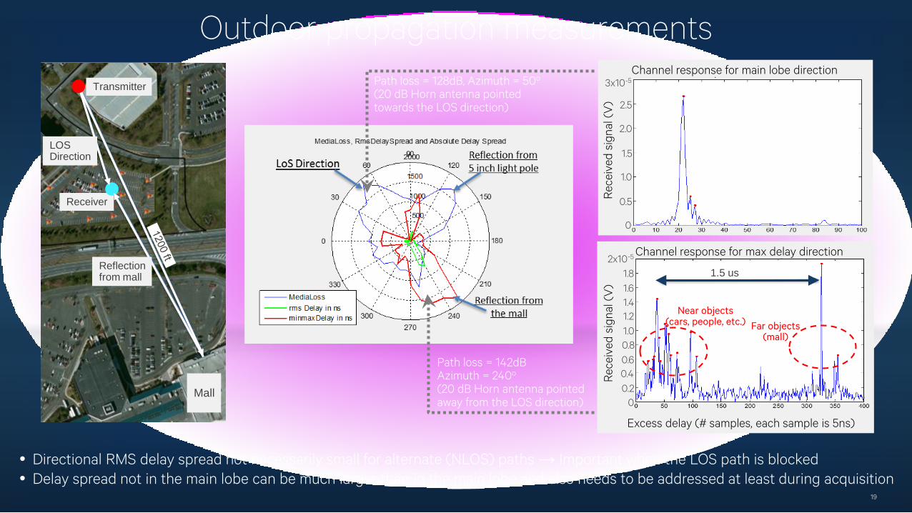
Outdoor propagation measurements
19
Transmitter
Receiver
Mall
LOSDirection
Reflectionfrom mall
Path loss = 128dB, Azimuth = 50o
(20 dB Horn antenna pointed towards the LOS direction)
Path loss = 142dBAzimuth = 240o
(20 dB Horn antenna pointed away from the LOS direction)
1.5 us
Main lobe(AZ = 50 degree)
Near objects(cars, people, etc.) Far objects
(mall)
Excess delay (# samples, each sample is 5ns)
Rec
eive
d si
gnal
(V
)R
ecei
ved
sign
al (
V)
2.5
2.0
1.5
1.0
0.5
0
3x10⁻⁵
1.8
1.00.8
1.61.41.2
0.20
0.60.4
Channel response for main lobe direction
Channel response for max delay direction2x10-5
• Directional RMS delay spread not necessarily small for alternate (NLOS) paths → Important when the LOS path is blocked• Delay spread not in the main lobe can be much larger than in the main lobe and also needs to be addressed at least during acquisition
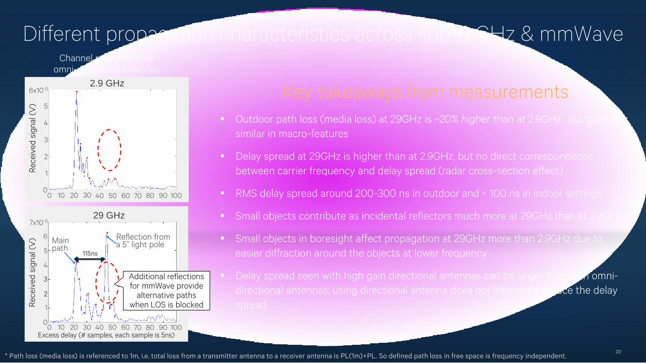
Different propagation characteristics across sub-6 GHz & mmWave
20
Channel response fromomni-directional antennas
Key takeaways from measurements• Outdoor path loss (media loss) at 29GHz is ~20% higher than at 2.9GHz*, but generally
similar in macro-features
• Delay spread at 29GHz is higher than at 2.9GHz, but no direct correspondence between carrier frequency and delay spread (radar cross-section effect)
• RMS delay spread around 200-300 ns in outdoor and < 100 ns in indoor settings
• Small objects contribute as incidental reflectors much more at 29GHz than at 2.9GHz
• Small objects in boresight affect propagation at 29GHz more than 2.9GHz due to easier diffraction around the objects at lower frequency
• Delay spread seen with high gain directional antennas can be larger than with omni-directional antennas; using directional antenna does not inherently reduce the delay spread
2.9 GHz
29 GHz
Rec
eive
d si
gnal
(V
) 5
4
3
2
1
0
6x10⁻⁵
Rec
eive
d si
gnal
(V
) 6
5
4
3
1
0
2
7x10⁻⁵
0 10 20 30 40 50 60 70 80 90 100
0 10 20 30 40 50 60 70 80 90 100Excess delay (# samples, each sample is 5ns)
80 90 100
Mainpath
Reflection froma 5” light pole
Additional reflections for mmWave provide
alternative paths when LOS is blocked
115ns
* Path loss (media loss) is referenced to 1m, i.e. total loss from a transmitter antenna to a receiver antenna is PL(1m)+PL. So defined path loss in free space is frequency independent.
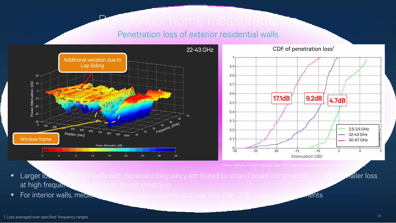
Residential home measurementsPenetration loss of exterior residential walls
21
22-43 GHz
Additional variation due to Lap Siding
Window frame
• Larger loss for exterior walls with increased frequency attributed to strand board construction → much smaller loss at high frequencies for plywood based sheathing
• For interior walls, median penetration loss is smaller and was less than 3dB in most measurements
1. Loss averaged over specified frequency ranges
CDF of penetration loss1
Attenuation (dB)
2.5-3.5 GHz22-43 GHz50-67 GHz
4.7dB9.2dB17.1dB
Note: Values in red indicate the 50th percentile penetration loss for the bands
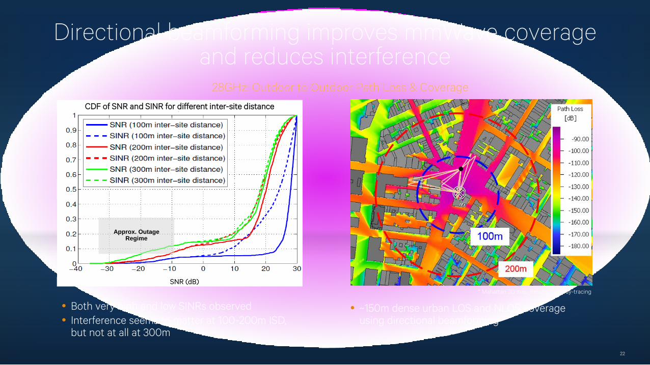
Directional beamforming improves mmWave coverage and reduces interference
22
• Both very high and low SINRs observed • Interference seems to matter at 100-200m ISD,
but not at all at 300m
28GHz: Outdoor to Outdoor Path Loss & Coverage
* Mahattan 3D map, Results from ray-tracing
• ~150m dense urban LOS and NLOS coverage using directional beamforming
CDF of SNR and SINR for different inter-site distance
SNR (dB)
Approx. Outage Regime
Device-centric mobility management in 5GControl plane improvements to improve energy and overhead efficiency
23
1 Coordinated MultiPoint is an LTE Advanced feature to send and receive data to and from a UE from several access nodes to ensure the optimum performance is achieved even at cell edges; 2 May dynamically revert to broadcast system info when needed, e.g. system info changes
Serving cluster
Mobility zone (area of tightly coordinated cells)
Lightweight mobility for device energy savings
• Apply COMP-like1 concepts to the control plane
• Intra-zone mobility transparent to the device
Less broadcast for network energy savings
• Low periodic beacon for initial discovery of device(s)
• On-demand system info (SIB) when devices present2
Periodic Sync
SIB request
Transmit SIB
No SIB request
No SIB transmission
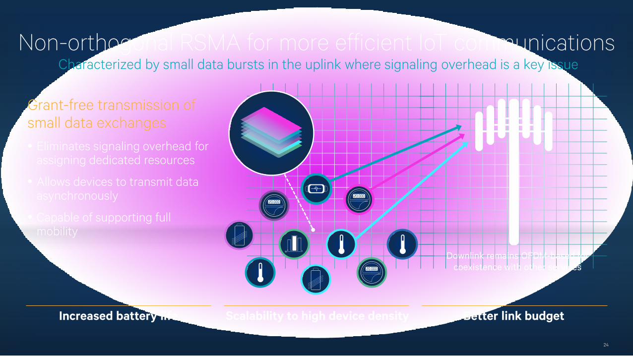
Non-orthogonal RSMA for more efficient IoT communicationsCharacterized by small data bursts in the uplink where signaling overhead is a key issue
24
Grant-free transmission of small data exchanges• Eliminates signaling overhead for
assigning dedicated resources
• Allows devices to transmit data asynchronously
• Capable of supporting full mobility
Increased battery life Scalability to high device density Better link budget
Downlink remains OFDM-based for coexistence with other services
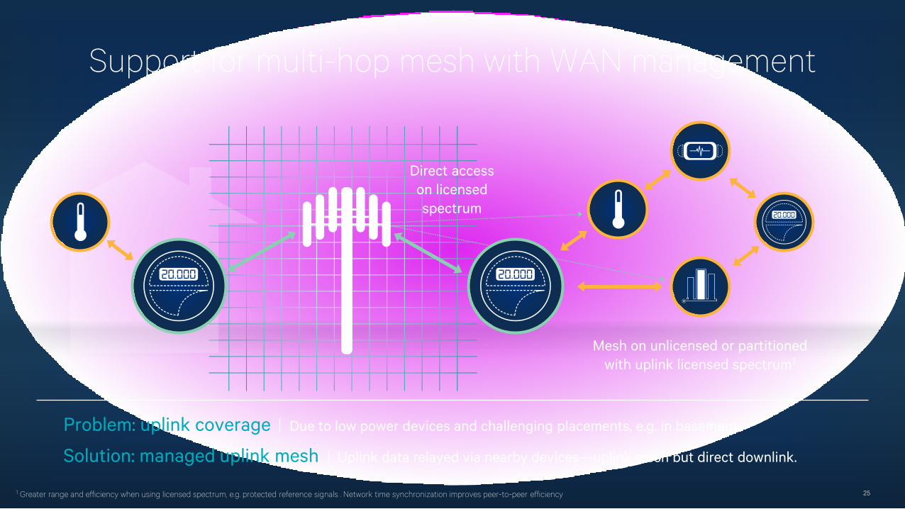
Support for multi-hop mesh with WAN management
Direct access on licensedspectrum
1 Greater range and efficiency when using licensed spectrum, e.g. protected reference signals . Network time synchronization improves peer-to-peer efficiency
Problem: uplink coverage Due to low power devices and challenging placements, e.g. in basement
Solution: managed uplink mesh Uplink data relayed via nearby devices—uplink mesh but direct downlink.
Mesh on unlicensed or partitioned with uplink licensed spectrum1
25
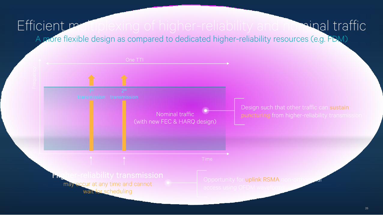
Efficient multiplexing of higher-reliability and nominal trafficA more flexible design as compared to dedicated higher-reliability resources (e.g. FDM)
26
Design such that other traffic can sustain puncturing from higher-reliability transmission
Higher-reliability transmissionmay occur at any time and cannot
wait for scheduling
Nominal traffic(with new FEC & HARQ design)
Time
Freq
uenc
y
One TTI
1st
transmission2st
transmission
Opportunity for uplink RSMA non-orthogonal access using OFDM waveforms
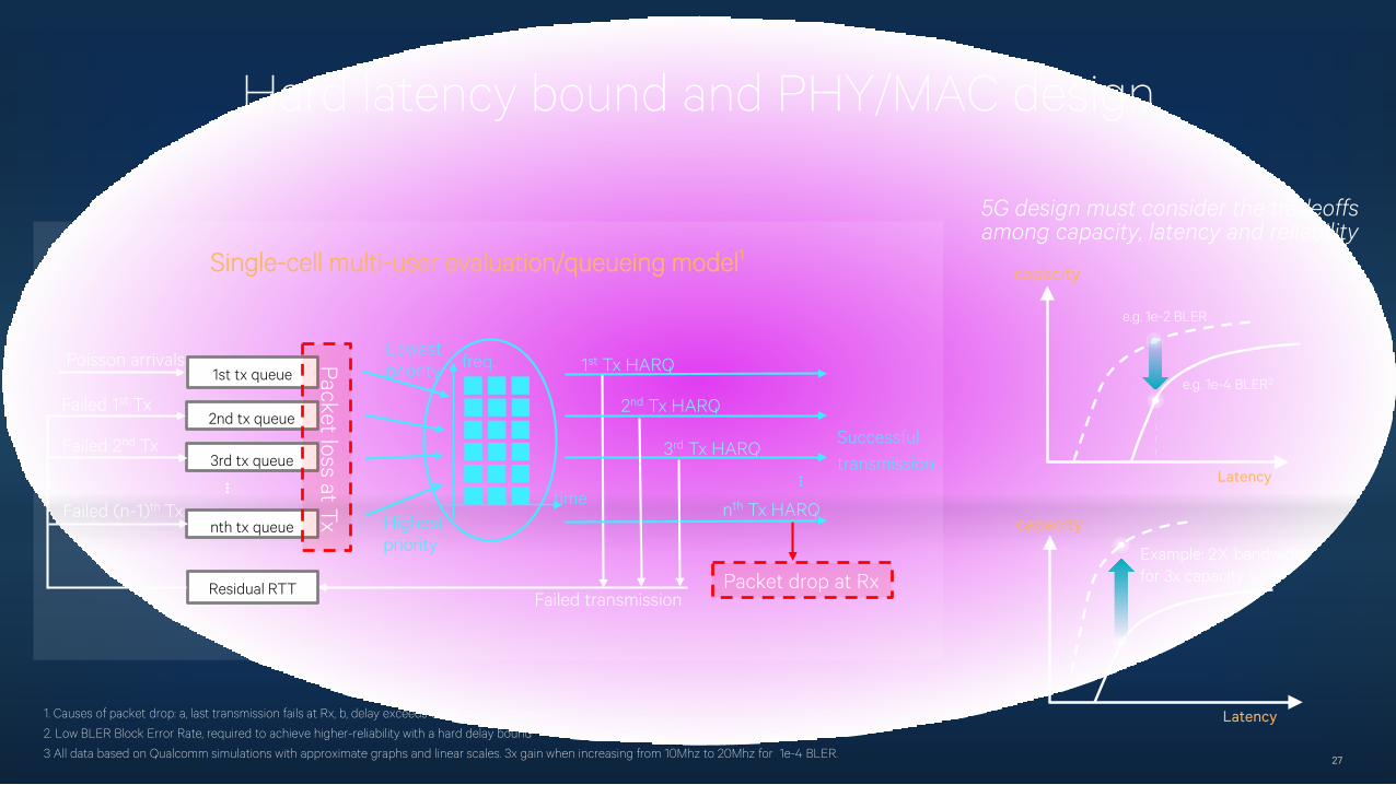
Hard latency bound and PHY/MAC design
27
2nd tx queue
1st tx queue
Residual RTT
Poisson arrivals
3rd tx queue
nth tx queue
time
freq.
...
1st Tx HARQ
2nd Tx HARQ
3rd Tx HARQ
nth Tx HARQ
Packet drop at Rx
Successfultransmission
Failed transmission
Failed 1st Tx
Failed 2nd Tx
Failed (n-1)th Tx
...
Highestpriority
LowestpriorityPacket loss at Tx
Single-cell multi-user evaluation/queueing model1
Latency
e.g. 1e-4 BLER2
e.g. 1e-2 BLER
capacity
5G design must consider the tradeoffs among capacity, latency and reliability
Example: 2X bandwidth for 3x capacity gain3
capacity
Latency1. Causes of packet drop: a, last transmission fails at Rx, b, delay exceeds deadline at Tx queues
2. Low BLER Block Error Rate, required to achieve higher-reliability with a hard delay bound
3 All data based on Qualcomm simulations with approximate graphs and linear scales. 3x gain when increasing from 10Mhz to 20Mhz for 1e-4 BLER.
For more information on Qualcomm, visit us at: www.qualcomm.com & www.qualcomm.com/blog
Thank youFollow us on:
Nothing in these materials is an offer to sell any of the components or devices referenced herein.
©2013-2015 Qualcomm Technologies, Inc. and/or its affiliated companies. All Rights Reserved.
Qualcomm, Snapdragon and VIVE are trademarks of Qualcomm Incorporated, registered in the United States and other countries, used with permission. Other products and brand names may be trademarks or registered trademarks of their respective owners.
References in this presentation to “Qualcomm” may mean Qualcomm Incorporated, Qualcomm Technologies, Inc., and/or other subsidiaries or business units within the Qualcomm corporate structure, as applicable.
Qualcomm Incorporated includes Qualcomm’s licensing business, QTL, and the vast majority of its patent portfolio. Qualcomm Technologies, Inc., a wholly-owned subsidiary of Qualcomm Incorporated, operates, along with its subsidiaries, substantially all of Qualcomm’s engineering, research and development functions, and substantially all of its product and services businesses, including its semiconductor business, QCT.
28