Embed Size (px)
Citation preview
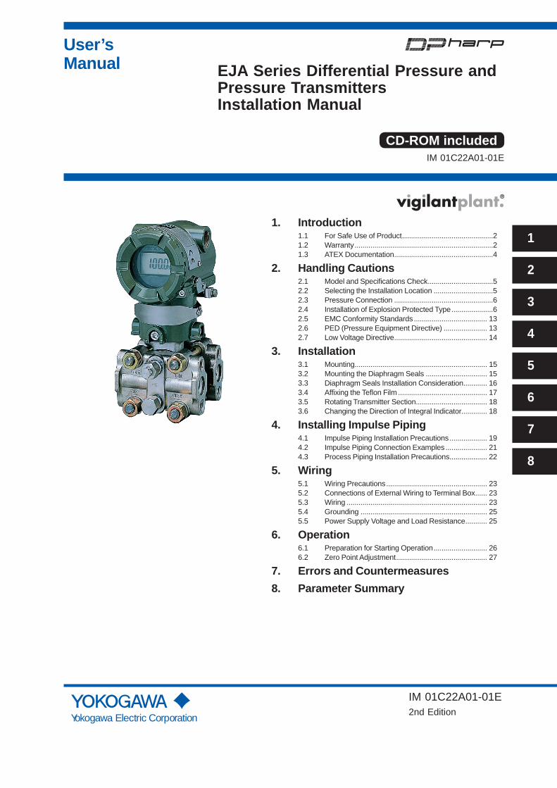
User’sManual
Yokogawa Electric Corporation
1
2
3
4
5
6
7
8
EJA Series Differential Pressure and Pressure TransmittersInstallation Manual
IM 01C22A01-01E
IM 01C22A01-01E2nd Edition
CD-ROM included
1. Introduction1.1 For Safe Use of Product ..............................................21.2 Warranty ......................................................................21.3 ATEX Documentation ..................................................4
2. Handling Cautions2.1 Model and Specifi cations Check .................................52.2 Selecting the Installation Location ..............................52.3 Pressure Connection ..................................................62.4 Installation of Explosion Protected Type .....................62.5 EMC Conformity Standards ..................................... 132.6 PED (Pressure Equipment Directive) ...................... 132.7 Low Voltage Directive ............................................... 14
3. Installation3.1 Mounting................................................................... 153.2 Mounting the Diaphragm Seals ............................... 153.3 Diaphragm Seals Installation Consideration ............ 163.4 Affi xing the Tefl on Film ............................................. 173.5 Rotating Transmitter Section .................................... 183.6 Changing the Direction of Integral Indicator............. 18
4. Installing Impulse Piping4.1 Impulse Piping Installation Precautions ................... 194.2 Impulse Piping Connection Examples ..................... 214.3 Process Piping Installation Precautions ................... 22
5. Wiring5.1 Wiring Precautions ................................................... 235.2 Connections of External Wiring to Terminal Box ...... 235.3 Wiring ....................................................................... 235.4 Grounding ................................................................ 255.5 Power Supply Voltage and Load Resistance ........... 25
6. Operation6.1 Preparation for Starting Operation ........................... 266.2 Zero Point Adjustment .............................................. 27
7. Errors and Countermeasures8. Parameter Summary

<1. Introduction> 1
IM 01C22A01-01E
1. IntroductionThank you for purchasing the DPharp electronic pressure transmitter.
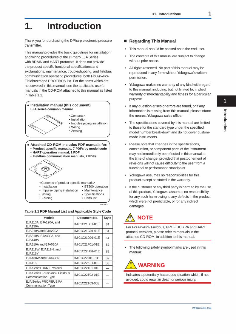
This manual provides the basic guidelines for installation and wiring procedures of the DPharp EJA Series with BRAIN and HART protocols. It does not provide the product specifi c functional specifi cations and explanations, maintenance, troubleshooting, and fi eldbus communication operating procedures, both FOUNDATION FieldbusTM and PROFIBUS PA. For the items which are not covered in this manual, see the applicable user’s manuals in the CD-ROM attached to this manual as listed in Table 1.1.
F0101.ai
● Installation manual (this document) EJA series common manual
<Contents>• Installation• Impulse piping installation• Wiring• Zeroing
● Attached CD-ROM includes PDF manuals for:• Product specific manuals, 7 PDFs by model code• HART operation manual, 1 PDF• Fieldbus communication manuals, 2 PDFs
<Contents of product specific manuals>• Installation • BT200 operation• Impulse piping installation • Maintenance• Wiring • Specifications• Zeroing • Parts list
Table 1.1 PDF Manual List and Applicable Style Code
Models Document No. StyleEJA110A, EJA120A, and EJA130A
IM 01C21B01-01E S1
EJA210A and EJA220A IM 01C21C01-01E S1EJA310A, EJA430A, and EJA440A
IM 01C21D01-01E S1
EJA510A and EJA530A IM 01C21F01-01E S2EJA118W, EJA118N, and EJA118Y
IM 01C22H01-01E S2
EJA438W and EJA438N IM 01C22J01-01E S2EJA115 IM 01C22K01-01E S3EJA Series HART Protocol IM 01C22T01-01E —EJA Series FOUNDATION Fieldbus Communication Type
IM 01C22T02-01E —
EJA Series PROFIBUS PA Communication Type
IM 01C22T03-00E —
Regarding This Manual
• This manual should be passed on to the end user.
• The contents of this manual are subject to change without prior notice.
• All rights reserved. No part of this manual may be reproduced in any form without Yokogawa’s written permission.
• Yokogawa makes no warranty of any kind with regard to this manual, including, but not limited to, implied warranty of merchantability and fi tness for a particular purpose.
• If any question arises or errors are found, or if any information is missing from this manual, please inform the nearest Yokogawa sales offi ce.
• The specifi cations covered by this manual are limited to those for the standard type under the specifi ed model number break-down and do not cover custom-made instruments.
• Please note that changes in the specifi cations, construction, or component parts of the instrument may not immediately be refl ected in this manual at the time of change, provided that postponement of revisions will not cause diffi culty to the user from a functional or performance standpoint.
• Yokogawa assumes no responsibilities for this product except as stated in the warranty.
• If the customer or any third party is harmed by the use of this product, Yokogawa assumes no responsibility for any such harm owing to any defects in the product which were not predictable, or for any indirect damages.
NOTEFor FOUNDATION Fieldbus, PROFIBUS PA and HART protocol versions, please refer to manuals in the attached CD-ROM, in addition to this manual.
• The following safety symbol marks are used in this manual:
WARNING
Indicates a potentially hazardous situation which, if not avoided, could result in death or serious injury.
1
Introduction
<1. Introduction> 2
IM 01C22A01-01E
CAUTIONIndicates a potentially hazardous situation which, if not avoided, may result in minor or moderate injury. It may also be used to alert against unsafe practices.
IMPORTANTIndicates that operating the hardware or software in this manner may damage it or lead to system failure.
NOTEDraws attention to information essential for understanding the operation and features.
Direct current
1.1 For Safe Use of ProductFor the protection and safety of the operator and the instrument or the system including the instrument, please be sure to follow the instructions on safety described in this manual when handling this instrument. In case the instrument is handled in contradiction to these instructions, Yokogawa does not guarantee safety. Please give your attention to the followings.
(a) Installation
• The instrument must be installed by an expert engineer or a skilled personnel. The procedures described about INSTALLATION are not permitted for operators.
• In case of high process temperature, care should be taken not to burn yourself because the surface of body and case reaches a high temperature.
• The instrument installed in the process is under pressure. Never loosen the process connector bolts to avoid the dangerous spouting of process fl uid.
• During draining condensate from the pressure detector section, take appropriate care to avoid contact with the skin, eyes or body, or inhalation of vapors, if the accumulated process fl uid may be toxic or otherwise harmful.
• When removing the instrument from hazardous processes, avoid contact with the fl uid and the interior of the meter.
• All installation shall comply with local installation requirement and local electrical code.
(b) Wiring
• The instrument must be installed by an expert engineer or a skilled personnel. The procedures described about WIRING are not permitted for operators.
• Please confi rm that voltages between the power supply and the instrument before connecting the power cables and that the cables are not powered before connecting.
(c) Operation
• Wait 10 min. after power is turned off, before opening the covers.
(d) Maintenance
• Please do not carry out except being written to maintenance descriptions. When these procedures are needed, please contact nearest YOKOGAWA offi ce.
• Care should be taken to prevent the build up of drift, dust or other material on the display glass and name plate. In case of its maintenance, soft and dry cloth is used.
(e) Explosion Protected Type Instrument
• Users of explosion proof instruments should refer fi rst to section 2.4 (Installation of an Explosion Protected Instrument) of this manual.
• The use of this instrument is restricted to those who have received appropriate training in the device.
• Take care not to create sparks when accessing the instrument or peripheral devices in a hazardous location.
(f) Modifi cation
• Yokogawa will not be liable for malfunctions or damage resulting from any modifi cation made to this instrument by the customer.
1.2 Warranty• The warranty shall cover the period noted on the
quotation presented to the purchaser at the time of purchase. Problems occurred during the warranty period shall basically be repaired free of charge.
• In case of problems, the customer should contact the Yokogawa representative from which the instrument was purchased, or the nearest Yokogawa offi ce.
• If a problem arises with this instrument, please inform us of the nature of the problem and the circumstances under which it developed, including the model specifi cation and serial number. Any diagrams, data and other information you can include in your communication will also be helpful.
<1. Introduction> 3
IM 01C22A01-01E
• Responsible party for repair cost for the problems shall be determined by Yokogawa based on our investigation.
• The Purchaser shall bear the responsibility for repair costs, even during the warranty period, if the malfunction is due to:
- Improper and/or inadequate maintenance by the purchaser.
- Failure or damage due to improper handling, use or storage which is out of design conditions.
- Use of the product in question in a location not conforming to the standards specifi ed by Yokogawa, or due to improper maintenance of the installation location.
- Failure or damage due to modifi cation or repair by any party except Yokogawa or an approved representative of Yokogawa.
- Malfunction or damage from improper relocation of the product in question after delivery.
- Reason of force majeure such as fi res, earthquakes, storms/fl oods, thunder/lightening, or other natural disasters, or disturbances, riots, warfare, or radioactive contamination.
1
Introduction
<1. Introduction> 4
IM 01C22A01-01E
1.3 ATEX DocumentationThis is only applicable to the countries in European Union.
GB
DK
I
E
NL
SF
P
F
D
S
LT
LV
PL
EST
SLO
H
BG
RO
M
CZ
SK
GR
<2. Handling Cautions> 5
IM 01C22A01-01E
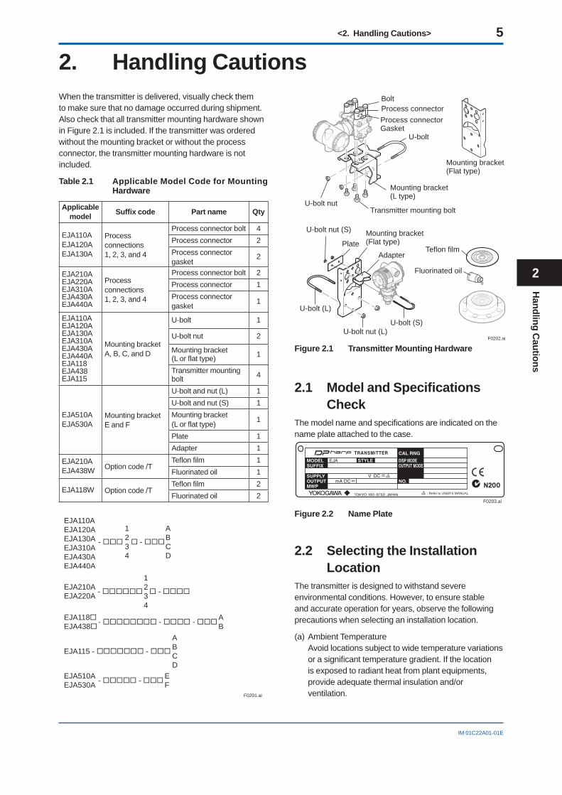
2. Handling CautionsWhen the transmitter is delivered, visually check them to make sure that no damage occurred during shipment. Also check that all transmitter mounting hardware shown in Figure 2.1 is included. If the transmitter was ordered without the mounting bracket or without the process connector, the transmitter mounting hardware is not included.
Table 2.1 Applicable Model Code for Mounting Hardware
Applicable model Suffi x code Part name Qty
EJA110AEJA120AEJA130A
Process connections1, 2, 3, and 4
Process connector bolt 4Process connector 2Process connector gasket
2
EJA210AEJA220AEJA310AEJA430AEJA440A
Process connections1, 2, 3, and 4
Process connector bolt 2Process connector 1Process connector gasket 1
EJA110AEJA120AEJA130AEJA310AEJA430AEJA440AEJA118EJA438EJA115
Mounting bracket A, B, C, and D
U-bolt 1
U-bolt nut 2
Mounting bracket (L or fl at type) 1
Transmitter mounting bolt 4
EJA510AEJA530A
Mounting bracket E and F
U-bolt and nut (L) 1U-bolt and nut (S) 1Mounting bracket (L or fl at type) 1
Plate 1Adapter 1
EJA210AEJA438W Option code /T
Tefl on fi lm 1Fluorinated oil 1
EJA118W Option code /TTefl on fi lm 2Fluorinated oil 2
EJA110AEJA120AEJA130AEJA310AEJA430AEJA440A
-
1234
-
ABCD
EJA115 - -
ABCD
EJA210AEJA220A
1234
- -
EJA118EJA438
AB - - -
F0201.ai
EJA510AEJA530A
EF - -
BoltProcess connectorProcess connectorGasket
U-bolt nut
U-bolt
Mounting bracket(L type)
Transmitter mounting bolt
Mounting bracket(Flat type)
F0202.ai
Teflon film
Fluorinated oil
U-bolt nut (S)
Plate
U-bolt nut (L)
U-bolt (L)
Mounting bracket(Flat type)
Adapter
U-bolt (S)
Figure 2.1 Transmitter Mounting Hardware
2.1 Model and Specifi cations Check
The model name and specifi cations are indicated on the name plate attached to the case.
F0203.ai
: Refer to USER'S MANUAL
Figure 2.2 Name Plate
2.2 Selecting the Installation Location
The transmitter is designed to withstand severe environmental conditions. However, to ensure stable and accurate operation for years, observe the following precautions when selecting an installation location.
(a) Ambient TemperatureAvoid locations subject to wide temperature variations or a signifi cant temperature gradient. If the location is exposed to radiant heat from plant equipments, provide adequate thermal insulation and/or ventilation.
Handling C
autions
2
<2. Handling Cautions> 6
IM 01C22A01-01E
(b) Ambient Atmosphere Avoid installing the transmitter in a corrosive
atmosphere. If the transmitter must be installed in a corrosive atmosphere, there must be adequate ventilation as well as measures to prevent intrusion or stagnation of rain water in conduits.
(c) Shock and Vibration Select an installation site suffering minimum shock
and vibration (although the transmitter is designed to be relatively resistant to shock and vibration).
(d) Installation of Explosion-protected Transmitters Explosion-protected transmitters can be installed
in hazardous areas according to the types of gases for which they are certifi ed. See Subsection 2.4 “Installation of Explosion Protected Type Transmitters.”
2.3 Pressure Connection
WARNING
• Instrument installed in the process is under pressure. Never loosen the process connector bolts to avoid the dangerous spouting of process fl uid.
• During draining condensate from the pressure detector section, take appropriate care to avoid contact with the skin, eyes or body, or inhalation of vapors, if the accumulated process fl uid may be toxic or otherwise harmful.
The following precautions must be observed in order to safely operate the transmitter under pressure.
(a) Make sure that the process connector bolts are tightened fi rmly.
(b) Make sure that there are no leaks in the impulse piping.
(c) Never apply a pressure higher than the specifi ed maximum working pressure.
CAUTIONMaximum working pressure of the model EJA120A differential pressure transmitter is 50 kPa {0.5 kgf/cm2}.Should the pressure exceed 50 kPa {0.5 kgf/cm2}, it is possible to break the sensor. Proceed with caution when applying pressure.
2.4 Installation of Explosion Protected Type
In this section, further requirements and differences and for explosionproof type instrument are described.
For explosionproof type instrument, the description in this chapter is prior to other description in this users manual.
For the intrinsically safe equipment and explosionproof equipment, in case the instrument is not restored to its original condition after any repair or modifi cation undertaken by the customer, intrinsically safe construction or explosionproof construction is damaged and may cause dangerous condition. Please contact Yokogawa for any repair or modifi cation required to the instrument.
NOTEFor FOUNDATION Fieldbus and PROFIBUS PA explosion protected type, please refer to manuals in the attached CD-ROM.
CAUTIONThis instrument is tested and certifi ed as intrinsically safe type or explosionproof type. Please note that the construction of the instrument, installation, external wiring, maintenance or repair is strictly restricted, and non-observance or negligence of this restriction would result in dangerous condition.
WARNING
To preserve the safety of explosionproof equipment requires great care during mounting, wiring, and piping. Safety requirements also place restrictions on maintenance and repair activities. Please read the following sections very carefully.
2.4.1 FM Approval
a. FM Intrinsically Safe Type
Caution for FM intrinsically safe type. (Following contents refer “DOC. No. IFM012-A12 P.1 and 2.”)
Note 1. Model EJA Series pressure transmitters with optional code /FS1 are applicable for use in hazardous locations.
• Applicable Standard: FM3600, FM3610, FM3611, FM3810, ANSI/NEMA250
<2. Handling Cautions> 7
IM 01C22A01-01E
• Intrinsically Safe for Class I, Division 1, Groups A, B, C & D. Class II, Division 1, Groups E, F & G and Class III, Division 1 Hazardous Locations.
• Nonincendive for Class I, Division 2, Groups A, B, C & D. Class II, Division 2, Groups E, F & G and Class III, Division 1 Hazardous Locations.
• Outdoor hazardous locations, NEMA 4X.• Temperature Class: T4• Ambient temperature: –40 to 60°C
Note 2. Entity Parameters• Intrinsically Safe Apparatus Parameters [Groups A, B, C, D, E, F and G] Vmax = 30 V, Ci = 22.5 nF, Imax = 165 mA,
Li = 730 μH, Pmax = 0.9 W* Associated Apparatus Parameters
(FM approved barriers) Voc ≤ 30 V, Ca > 22.5 nF, Isc ≤ 165 mA, La > 730 μH,
Pmax ≤ 0.9W• Intrinsically Safe Apparatus Parameters [Groups C, D, E, F and G] Vmax = 30 V, Ci = 22.5 nF, Imax = 225 mA,
Li = 730 μH, Pmax = 0.9 W* Associated Apparatus Parameters
(FM approved barriers) Voc ≤ 30 V, Ca > 22.5 nF, Isc ≤ 225 mA,
La > 730 μH, Pmax ≤ 0.9 W• Entity Installation Requirements Vmax ≥ Voc or Vt, Imax ≥ Isc or It,
Pmax (IS Apparatus) ≥ Pmax (Barrier), Ca ≥ Ci + Ccable, La ≥ Li + Lcable
Note 3. Installation• Barrier must be installed in an enclosure that meets
the requirements of ANSI/ISA S82.01.• Control equipment connected to barrier must not use
or generate more than 250 V rms or V dc.• Installation should be in accordance with ANSI/ISA
RP12.6 “Installation of Intrinsically Safe Systems for Hazardous (Classifi ed) Locations” and the National Electric Code (ANSI/NFPA 70).
• The confi guration of associated apparatus must be FMRC Approved.
• Dust-tight conduit seal must be used when installed in a Class II, III, Group E, F and G environments.
• Associated apparatus manufacturer’s installation drawing must be followed when installing this apparatus.
• The maximum power delivered from the barrier must not exceed 0.9 W.
• Note a warning label worded “SUBSTITUTION OF COMPONENTS MAY IMPAIR INTRINSIC SAFETY,” and “INSTALL IN ACCORDANCE WITH DOC. No. IFM012-A12 P.1 and 2.”
Note 4. Maintenance and Repair• The instrument modifi cation or parts replacement by
other than authorized representative of Yokogawa Electric Corporation is prohibited and will void Factory Mutual Intrinsically safe and Nonincendive Approval.
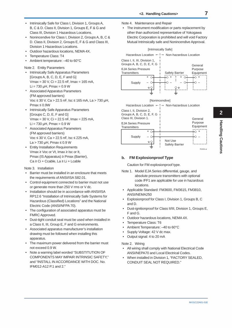
F0204.ai
Class I, II, III, Division 1, Groups A, B, C, D, E, F, G EJA Series Pressure Transmitters
EJA Series Pressure Transmitters
Safety Barrier
Supply
Supply
Hazardous Location Non-hazardous Location
Hazardous Location Non-hazardous Location
GeneralPurposeEquipment
+
–
+
–
+
–
+
–
+
–
+
–
[Intrinsically Safe]
Class I, II, Division 2, Groups A, B, C, D, E, F, G Class III, Division 1.
Not Use Safety Barrier
[Nonincendive]
GeneralPurposeEquipment
b. FM Explosionproof Type
Caution for FM explosionproof type.
Note 1. Model EJA Series differential, gauge, and absolute pressure transmitters with optional code /FF1 are applicable for use in hazardous locations.
• Applicable Standard: FM3600, FM3615, FM3810, ANSI/NEMA250
• Explosionproof for Class I, Division 1, Groups B, C and D.
• Dust-ignitionproof for Class II/III, Division 1, Groups E, F and G.
• Outdoor hazardous locations, NEMA 4X.• Temperature Class: T6• Ambient Temperature: –40 to 60°C• Supply Voltage: 42 V dc max.• Output signal: 4 to 20 mA
Note 2. Wiring• All wiring shall comply with National Electrical Code
ANSI/NEPA70 and Local Electrical Codes.• When installed in Division 1, “FACTORY SEALED,
CONDUIT SEAL NOT REQUIRED.”
Handling C
autions
2
<2. Handling Cautions> 8
IM 01C22A01-01E
Note 3. Operation• Keep the “CAUTION” nameplate attached to the
transmitter. CAUTION: OPEN CIRCUIT BEFORE
REMOVING COVER. FACTORY SEALED, CONDUIT SEAL NOT REQUIRED. INSTALL IN ACCORDANCE WITH THE INSTRUCTION MANUAL IM 1C22.
• Take care not to generate mechanical sparking when accessing to the instrument and peripheral devices in a hazardous location.
Note 4. Maintenance and Repair• The instrument modifi cation or parts replacement by
other than authorized representative of Yokogawa Electric Corporation is prohibited and will void Factory Mutual Explosionproof Approval.
c. FM Intrinsically Safe Type/FM Explosionproof Type
Model EJA Series pressure transmitters with optional code /FU1 can be selected the type of protection (FM Intrinsically Safe or FM Explosionproof) for use in hazardous locations.
Note 1. For the installation of this transmitter, once a particular type of protection is selected, any other type of protection cannot be used. The installation must be in accordance with the description about the type of protection in this instruction manual.
Note 2. In order to avoid confusion, unnecessary marking is crossed out on the label other than the selected type of protection when the transmitter is installed.
2.4.2 CSA Certifi cation
a. CSA Intrinsically Safe Type
Caution for CSA Intrinsically safe type. (Following contents refer to “DOC No. ICS003-A12 P.1-1 and P.1-2.”)
Note 1. Model EJA Series differential, gauge, and absolute pressure transmitters with optional code /CS1 are applicable for use in hazardous locations
Certifi cate: 1053843• Applicable Standard: C22.2 No.0, No.0.4, No.25,
No.30, No.94, No.142, No.157, No.213• Intrinsically Safe for Class I, Division 1, Groups A,
B, C & D. Class II, Division 1, Groups E, F & G and Class III, Division 1 Hazardous Locations.
• Nonincendive for Class I, Division 2, Groups A, B, C & D, Class II, Division 2, Groups F & G, and Class III, Hazardous Locations. (not use Safety Barrier)
• Encl. “Type 4X”• Temperature Class: T4• Ambient temperature: –40 to 60°C• Process Temperature: 120°C max.
Note 2 Entity Parameters• Intrinsically safe ratings are as follows:
Maximum Input Voltage (Vmax) = 30 V Maximum Input Current (Imax) = 165 mA Maximum Input Power (Pmax) = 0.9 W Maximum Internal Capacitance (Ci) = 22.5 nF Maximum Internal Inductance (Li) = 730 μH* Associated apparatus (CSA certifi ed barriers) Maximum output voltage (Voc) ≤ 30 V Maximum output current (Isc) ≤ 165 mA Maximum output power (Pmax) ≤ 0.9 W
Note 3. Installation• All wiring shall comply with Canadian Electrical Code
Part I and Local Electrical Codes.• The instrument modifi cation or parts replacement by
other than authorized representative of Yokogawa Electric Corporation and Yokogawa Corporation of America is prohibited and will void Canadian Standards Intrinsically safe and nonincendive Certifi cation.
F0205.ai
Class I, II, III, Division 1,Groups A, B, C, D, E, F, GEJA Series Pressure Transmitters
EJA Series Pressure Transmitters
Safety Barrier
Supply
Supply
Hazardous Location Non-hazardous Location
Hazardous Location Non-hazardous Location
GeneralPurposeEquipment
+
–
+
–
+
–
+
–
+
–
+
–
[Intrinsically Safe]
Class I, II, Division 2,Groups A, B, C, D, E, F, GClass III, Division 1.
Not UseSafety Barrier
[Nonincendive]
GeneralPurposeEquipment
b. CSA Explosionproof Type
Caution for CSA explosionproof type.Note 1. Model EJA Series differential, gauge, and
absolute pressure transmitters with optional code /CF1 are applicable for use in hazardous locations:
Certifi cate: 1089598• Applicable Standard: C22.2 No.0, No.0.4, No.25,
No.30, No.94, No.142• Explosionproof for Class I, Division 1, Groups B, C
and D.• Dust-ignitionproof for Class II/III, Division 1, Groups E,
F and G.• Encl “Type 4X”
<2. Handling Cautions> 9
IM 01C22A01-01E
• Temperature Class: T6, T5, and T4• Process Temperature: 85°C (T6), 100°C (T5), and
120°C (T4)• Ambient Temperature: –40 to 80°C• Supply Voltage: 42 V dc max.• Output Signal: 4 to 20 mA
Note 2. Wiring• All wiring shall comply with Canadian Electrical Code
Part I and Local Electrical Codes.• In hazardous location, wiring shall be in conduit as
shown in the fi gure. CAUTION: SEAL ALL CONDUITS WITHIN 50
cm OF THE ENCLOSURE.UN SCELLEMENT DOIT ÊTRE INSTALLÉ À MOINS DE 50 cm DU BÎTIER.
• When installed in Division 2, “SEALS NOT REQUIRED.”
Note 3. Operation• Keep the “CAUTION” label attached to the transmitter.
CAUTION: OPEN CIRCUIT BEFORE REMOVING COVER. OUVRIR LE CIRCUIT AVANT D´NLEVER LE COUVERCLE.
• Take care not to generate mechanical sparking when accessing to the instrument and peripheral devices in a hazardous location.
Note 4. Maintenance and Repair• The instrument modifi cation or parts replacement by
other than authorized representative of Yokogawa Electric Corporation and Yokogawa Corporation of America is prohibited and will void Canadian Standards Explosionproof Certifi cation.
Non-hazardousLocationEquipment
42 V DC Max.4 to 20 mA DC Signal
Non-HazardousLocations
Hazardous Locations Division 1
Non-HazardousLocations
Hazardous Locations Division 2
50 cm Max.
Sealing Fitting Conduit
EJA Series
Non-hazardousLocationEquipment
42 V DC Max.4 to 20 mA DC Signal
Sealing Fitting
EJA Series F0206.ai
c. CSA Intrinsically Safe Type/CSA Explosionproof Type
Model EJA Series pressure transmitters with optional code /CU1 can be selected the type of protection (CSA Intrinsically Safe or CSA Explosionproof) for use in hazardous locations.
Note 1. For the installation of this transmitter, once a particular type of protection is selected, any other type of protection cannot be used. The installation must be in accordance with the description about the type of protection in this instruction manual.
Note 2. In order to avoid confusion, unnecessary marking is crossed out on the label other than the selected type of protection when the transmitter is installed.
2.4.3 IECEx Certifi cationModel EJA Series differential, gauge, and absolute pressure transmitters with optional code /SU2 can be selected the type of protection (IECEx Intrinsically Safe/type n or fl ameproof) for use in hazardous locations.
Note 1. For the installation of this transmitter, once a particular type of protection is selected, any other type of protection cannot be used. The installation must be in accordance with the description about the type of protection in this instruction manual.
Note 2. In order to avoid confusion, unnecessary marking is crossed out on the label other than the selected type of protection when the transmitter is installed.
a. IECEx Intrinsically Safe Type / type n
Caution for IECEx Intrinsically safe and type n.Note 1. Model EJA Series differential, gauge, and
absolute pressure transmitters with optional code /SU2 are applicable for use in hazardous locations.
• No. IECEx KEM 06.0007X• Applicable Standard: IEC 60079-0:2004,
IEC 60079-11:1999, IEC 60079-15:2005,IEC 60079-26:2004
• Type of Protection and Marking Code: Ex ia IIC T4, Ex nL IIC T4
• Ambient Temperature :–40 to 60°C• Max. Process Temp.: 120°C• Enclosure: IP67
Note 2. Entity Parameters• Intrinsically safe ratings are as follows:
Maximum Input Voltage (Ui) = 30 V Maximum Input Current (Ii) = 165 mA Maximum Input Power (Pi) = 0.9 W Maximum Internal Capacitance (Ci) = 22.5 nF Maximum Internal Inductance (Li) = 730 μH
Handling C
autions
2
<2. Handling Cautions> 10
IM 01C22A01-01E
• Type "n" ratings are as follows: Maximum Input Voltage (Ui) = 30 V Maximum Internal Capacitance (Ci) = 22.5 nF Maximum Internal Inductance (Li) = 730 μH
• Installation Requirements Uo ≤ Ui, Io ≤ Ii, Po ≤ Pi, Co ≥ Ci + Ccable, Lo ≥ Li + Lcable, Uo, Io, Po, Co, and Lo are parameters of barrier.
Note 3. Installation• In any safety barrier used output current must be
limited by a resistor 'R' such that Io=Uo/R.• The safety barrier must be IECEx certifi ed.• Input voltage of the safety barrier must be less than
250 Vrms/Vdc.• The instrument modifi cation or parts replacement by
other than authorized representative of Yokogawa Electric Corporation and will void IECEx Intrinsically safe and type n certifi cation.
• The cable entry devices and blanking elements for type n shall be of a certifi ed type providing a level of ingress protection of at least IP54, suitable for the conditions of use and correctly installed.
• Electrical Connection:The type of electrical connection is stamped near the electrical connection port according to the following marking.
F0207.ai
Location of the marking
Screw Size Marking
ISO M20 × 1.5 female M
AANSI 1/2 NPT female
Note 4. Operation• WARNING:
WHEN AMBIENT TEMPERATURE ≥ 55°C,USE THE HEAT-RESISTING CABLES ≥ 90°C.
Note 5. Special Conditions for Safe Use• WARNING:
IN THE CASE WHERE THE ENCLOSURE OF THE PRESSURE TRANSMITTER IS MADE OF ALUMINUM, IF IT IS MOUNTED IN AN AREA WHERE THE USE OF ZONE 0 IS REQUIRED, IT MUST BE INSTALLED SUCH, THAT, EVEN IN THE EVENT OF RARE INCIDENTS, IGNITION SOURCES DUE TO IMPACT AND FRICTION SPARKS ARE EXCLUDED.
F0208.ai
EJA Series Pressure Transmitters
Supply
Hazardous Location Non-hazardous Location
+
–
+
–Not UseSafety Barrier
[type n]
IECEx CertifiedEquipment [nL]
Group IIC, Zone 2
EJA Series Pressure Transmitters
IECEx certifiedSafety Barrier
Supply
Hazardous Location Non-hazardous Location
GeneralPurposeEquipment
+
–
+
–
+
–
+
–
[Intrinsically Safe]
Group I/IIC, Zone 0
b. IECEx Flameproof Type
Caution for IECEx fl ameproof type.Note 1. Model EJA Series differential, gauge, and
absolute pressure transmitters with optional code /SU2 are applicable for use in hazardous locations:
• No. IECEx KEM 06.0005• Applicable Standard: IEC60079-0:2004,
IEC60079-1:2003• Type of Protection and Marking Code:
Ex d IIC T6...T4• Enclosure: IP67• Maximum Process Temperature: 120°C (T4),
100°C (T5), 85°C (T6)• Ambient Temperature: –40 to 75°C (T4),
–40 to 80°C (T5), –40 to 75°C (T6)• Supply Voltage: 42 V dc max.• Output Signal: 4 to 20 mA dc
Note 2. Wiring• In hazardous locations, the cable entry devices shall
be of a certifi ed fl ameproof type, suitable for the conditions of use and correctly installed.
• Unused apertures shall be closed with suitable fl ameproof certifi ed blanking elements. (The plug attached is certifi cated as the fl ame proof IP67 as a part of this apparatus.)
• In case of ANSI 1/2 NPT plug, ANSI hexagonal wrench should be applied to screw in.
<2. Handling Cautions> 11
IM 01C22A01-01E
Note 3. Operation• WARNING:
AFTER DE-ENERGIZING, DELAY 10 MINUTES BEFORE OPENING.
• WARNING:WHEN AMBIENT TEMPERATURE ≥ 70°C, USE THE HEAT-RESISTING CABLES ≥ 90°C.
• Take care not to generate mechanical sparking when accessing to the instrument and peripheral devices in a hazardous location.
Note 4. Maintenance and Repair• The instrument modifi cation or parts replacement by
other than authorized representative of Yokogawa Electric Corporation is prohibited and will void IECEx Certifi cation.
2.4.4 CENELEC ATEX (KEMA) Certifi cation
(1) Technical Data
a. CENELEC ATEX (KEMA) Intrinsically Safe Type
Caution for CENELEC ATEX (KEMA) Intrinsically safe type.
Note 1. Model EJA Series differential, gauge, and absolute pressure transmitters with optional code /KS2 for potentially explosive atmospheres:
• No. KEMA 02ATEX1030 X• Applicable Standard: EN50014:1997, EN50020:1994,
EN50284:1999• Type of Protection and Marking code: EEx ia IIC T4• Temperature Class: T4• Enclosure: IP67• Process Temperature: 120°C max.• Ambient Temperature: –40 to 60°C
Note 2. Electrical Data• In type of explosion protection intrinsic safety EEx ia
IIC only for connection to a certifi ed intrinsically safe circuit with following maximum values: Ui = 30 V Ii = 165 mA Pi = 0.9 W Effective internal capacitance; Ci = 22.5 nF Effective internal inductance; Li = 730 μH
Note 3. Installation• All wiring shall comply with local installation
requirements. (Refer to the installation diagram)
Note 4. Maintenance and Repair• The instrument modifi cation or parts replacement by
other than authorized representative of Yokogawa Electric Corporation is prohibited and will void KEMA Intrinsically safe Certifi cation.
Note 5. Special Conditions for Safe Use• In the case where the enclosure of the Pressure
Transmitter is made of aluminium, if it is mounted in an area where the use of category 1 G apparatus is required, it must be installed such, that, even in the event of rare incidents, ignition sources due to impact and friction sparks are excluded.
Transmitter
Supply Safety Barrier *1
Non-hazardous Location
[Installation Diagram]
Hazardous Location
+
–
+
–
F0209.ai
*1: In any safety barriers used the output current must be limited by a resistor “R” such that Imaxout-Uz/R.
b. CENELEC ATEX (KEMA) Flameproof Type
Caution for CENELEC ATEX (KEMA) fl ameproof type.
Note 1. Model EJA Series differential, gauge, and absolute pressure transmitters with optional code /KF2 for potentially explosive atmospheres:
• No. KEMA 02ATEX2148• Applicable Standard: EN50014:1997, EN50018:2000• Type of Protection and Marking Code:
EEx d IIC T6···T4• Temperature Class: T6, T5, and T4• Enclosure: IP67• Maximum Process Temperature: 85°C (T6),
100°C (T5), and 120°C (T4)• Ambient Temperature: T4 and T6; –40 to 75°C,
T5; –40 to 80°C
Note 2. Electrical Data• Supply voltage: 42 V dc max.• Output signal: 4 to 20 mA
Note 3. Installation• All wiring shall comply with local installation
requirement.• The cable entry devices shall be of a certifi ed
fl ameproof type, suitable for the conditions of use.
Note 4. Operation• Keep the “CAUTION” label to the transmitter.
CAUTION: AFTER DE-ENERGIZING, DELAY 10 MINUTES BEFORE OPENING. WHEN THE AMBIENT TEMP.70°C, USE HEAT-RESISTING CABLES90°C.
• Take care not to generate mechanical sparking when accessing to the instrument and peripheral devices in a hazardous location.
Handling C
autions
2
<2. Handling Cautions> 12
IM 01C22A01-01E
Note 5. Maintenance and Repair• The instrument modifi cation or parts replacement by
other than authorized representative of Yokogawa Electric Corporation is prohibited and will void KEMA Flameproof Certifi cation.
c. CENELEC ATEX (KEMA) Intrinsically Safe Type/CENELEC ATEX (KEMA) Flameproof Type/CENELEC ATEX Type n
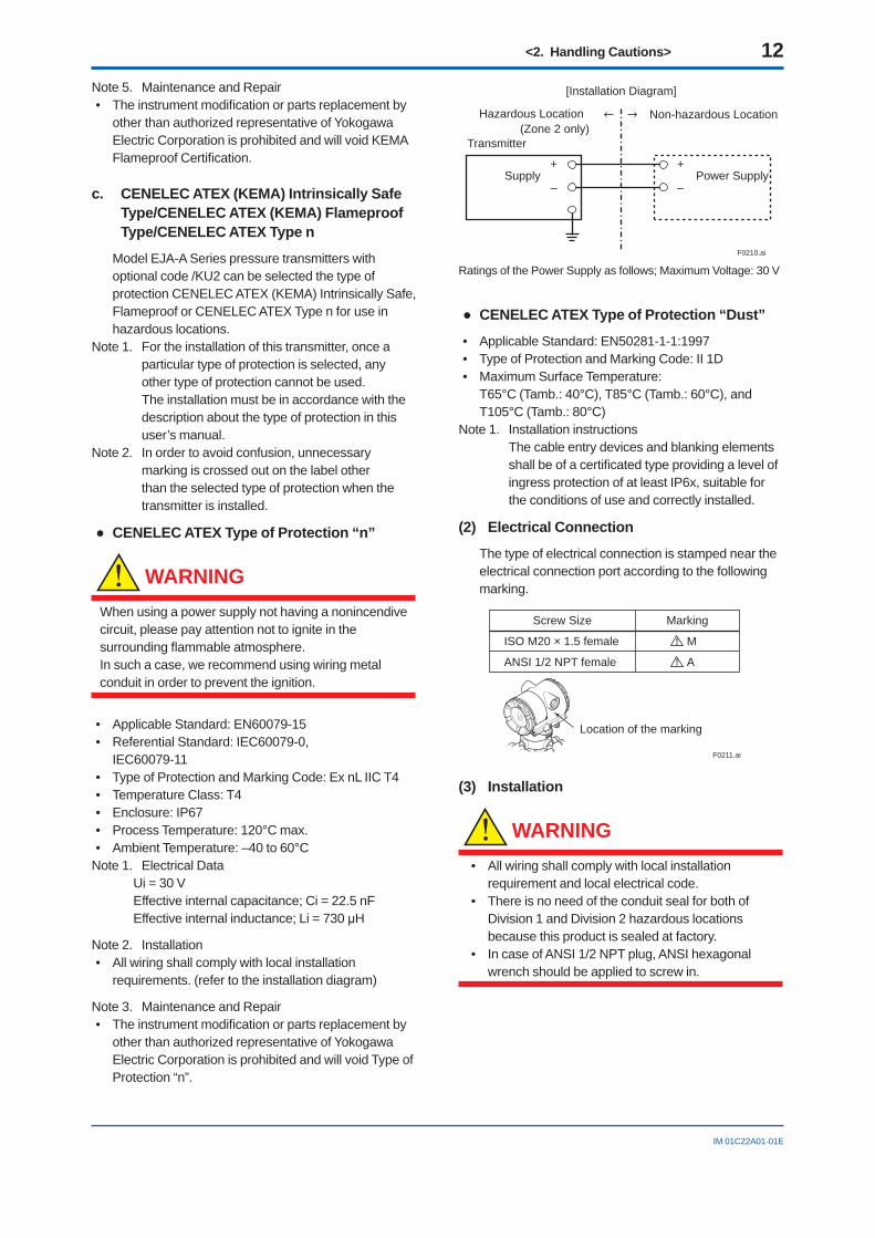
Model EJA-A Series pressure transmitters with optional code /KU2 can be selected the type of protection CENELEC ATEX (KEMA) Intrinsically Safe, Flameproof or CENELEC ATEX Type n for use in hazardous locations.
Note 1. For the installation of this transmitter, once a particular type of protection is selected, any other type of protection cannot be used.The installation must be in accordance with the description about the type of protection in this user’s manual.
Note 2. In order to avoid confusion, unnecessary marking is crossed out on the label other than the selected type of protection when the transmitter is installed.
● CENELEC ATEX Type of Protection “n”
WARNING
When using a power supply not having a nonincendive circuit, please pay attention not to ignite in the surrounding fl ammable atmosphere.In such a case, we recommend using wiring metal conduit in order to prevent the ignition.
• Applicable Standard: EN60079-15• Referential Standard: IEC60079-0,
IEC60079-11• Type of Protection and Marking Code: Ex nL IIC T4• Temperature Class: T4• Enclosure: IP67• Process Temperature: 120°C max.• Ambient Temperature: –40 to 60°C
Note 1. Electrical Data Ui = 30 V Effective internal capacitance; Ci = 22.5 nF Effective internal inductance; Li = 730 μH
Note 2. Installation• All wiring shall comply with local installation
requirements. (refer to the installation diagram)
Note 3. Maintenance and Repair• The instrument modifi cation or parts replacement by
other than authorized representative of Yokogawa Electric Corporation is prohibited and will void Type of Protection “n”.
Power Supply
(Zone 2 only) Transmitter
Supply
Non-hazardous Location
[Installation Diagram]
Hazardous Location
+
–
+
–
F0210.ai
Ratings of the Power Supply as follows; Maximum Voltage: 30 V
● CENELEC ATEX Type of Protection “Dust”
• Applicable Standard: EN50281-1-1:1997• Type of Protection and Marking Code: II 1D• Maximum Surface Temperature:
T65°C (Tamb.: 40°C), T85°C (Tamb.: 60°C), and T105°C (Tamb.: 80°C)
Note 1. Installation instructions The cable entry devices and blanking elements
shall be of a certifi cated type providing a level of ingress protection of at least IP6x, suitable for the conditions of use and correctly installed.
(2) Electrical Connection
The type of electrical connection is stamped near the electrical connection port according to the following marking.
F0211.ai
Location of the marking
Screw Size Marking
ISO M20 × 1.5 female M
AANSI 1/2 NPT female
(3) Installation
WARNING
• All wiring shall comply with local installation requirement and local electrical code.
• There is no need of the conduit seal for both of Division 1 and Division 2 hazardous locations because this product is sealed at factory.
• In case of ANSI 1/2 NPT plug, ANSI hexagonal wrench should be applied to screw in.
<2. Handling Cautions> 13
IM 01C22A01-01E
(4) Operation
WARNING
• OPEN CIRCUIT BEFORE REMOVING COVER. INSTALL IN ACCORDANCE WITH THIS USER’S MANUAL
• Take care not to generate mechanical sparking when access to the instrument and peripheral devices in hazardous locations.
(5) Maintenance and Repair
WARNING
The instrument modifi cation or parts replacement by other than authorized Representative of Yokogawa Electric Corporation is prohibited and will void the certifi cation.
(6) Name Plate
Name plate
: Refer to USER'S MANUAL
Tag plate for flameproof type
Tag plate for intrinsically safe type
Tag plate for type n protection
Tag plate for flameproof, intrinsically safe type, type n protection, and Dust
F0212.ai
D
MODEL: Specifi ed model code.STYLE: Style code.SUFFIX: Specifi ed suffi x code.SUPPLY: Supply voltage.OUTPUT: Output signal.
MWP: Maximum working pressure.CAL RNG: Specifi ed calibration range.DISP MODE: Specifi ed display mode.OUTPUT MODE: Specifi ed output mode.NO.: Serial number and year of production*1.
TOKYO 180-8750 JAPAN: The manufacturer name and the address*2.
*1: The third fi gure from the last shows the last one fi gure of the year of production. For example, the production year of the product engraved in “NO.” column on the name plate as follows is 2001.
12A819857 132
The year 2001*2: “180-8750” is a zip code which represents the following
address.
2-9-32 Nakacho, Musashino-shi, Tokyo Japan
2.5 EMC Conformity StandardsEN61326-1 Class A, Table 2 (For use in industrial locations)
EN61326-2-3
CAUTIONThis instrument is a Class A product, and it is designed for use in the industrial environment. Please use this instrument in the industrial environment only.
NOTEYOKOGAWA recommends customer to apply the Metal Conduit Wiring or to use the twisted pair Shield Cable for signal wiring to conform the requirement of EMC Regulation, when customer installs the EJA Series Transmitters to the plant.
2.6 PED (Pressure Equipment Directive)
(1) General
• EJA series of pressure transmitters are categorized as pressure accessories under the vessel section of this directive 97/23/EC, which corresponds to Article 3, Paragraph 3 of PED, denoted as Sound Engineering Practice (SEP).
• EJA130A, EJA440A, EJA510A, and EJA530A can be used above 200 bar and therefore considered as a part of a pressure retaining vessel where category lll, Module H applies. These models with option code /PE3 conform to that category.
Handling C
autions
2
<2. Handling Cautions> 14
IM 01C22A01-01E
(2) Technical Data
• Models without /PE3Article 3, Paragraph 3 of PED, denoted as Sound Engineering Practice (SEP) .
• Models with /PE3Module: HType of Equipment: Pressure Accessory - VesselType of Fluid: Liquid and GasGroup of Fluid: 1 and 2
Model PS*1
(bar) V(L) PS-V(bar-L) Category*2
EJA110A 160 0.01 1.6 Article 3, paragraph 3 (SEP)
EJA120A 0.5 0.01 0.005 Article 3, paragraph 3 (SEP)
EJA130A 420 0.01 4.2 Article 3, paragraph 3 (SEP)
EJA130A With code /PE3 420 0.01 4.2 III
EJA310A 160 0.01 1.6 Article 3, paragraph 3 (SEP)
EJA430A 160 0.01 1.6 Article 3, paragraph 3 (SEP)
EJA440A 500 0.01 50 Article 3, paragraph 3 (SEP)
EJA440AWith code /PE3 500 0.01 50 III
EJA510A 500 0.01 50 Article 3, paragraph 3 (SEP)
EJA510AWith code /PE3 500 0.01 50 III
EJA530A 500 0.01 50 Article 3, paragraph 3 (SEP)
EJA530A With code /PE3 500 0.01 50 III
*1: PS is maximum allowable pressure for vessel itself.*2: Referred to Table 1 covered by ANNEX II of EC Directive
on Pressure Equipment Directive 97/23/EC.
(3) Operation
CAUTION• The temperature and pressure of fl uid should be
applied under the normal operating condition.• The ambient temperature should be applied under
the normal operating condition.• Please pay attention to prevent the excessive
pressure like water hammer, etc. When water hammer is to be occurred, please take measures to prevent the pressure from exceeding PS by setting the safety valve, etc. at the system and the like.
• When external fi re is to be occurred, please take safety measures at the device or system not to infl uence the transmitters.
2.7 Low Voltage DirectiveApplicable standard : EN61010-1
(1) Pollution Degree 2
"Pollution degree" describes the degree to which a solid, liquid, or gas which deteriorates dielectric strength or surface resistivity is adhering. " 2 " applies to normal indoor atmosphere. Normally, only non-conductive pollution occurs. Occasionally, however, temporary conductivity caused by condensation must be expected.
(2) Installation Category I
"Overvoltage category(Installation category)" describes a number which defi nes a transient overvoltage condition. It implies the regulation for impulse withstand voltage. " I " applies to electrical equipment which is supplied from the circuit when appropriate transient overvoltage control means (interfaces) are provided.
<3. Installation> 15
IM 01C22A01-01E
3. InstallationIMPORTANT
• When welding piping during construction, take care not to allow welding currents to fl ow through the transmitter.
• Do not step on this instrument after installation.• For EJA430A, the atmospheric opening is located
on the low pressure side cover fl ange. For EJA530A with Measurement span code A, B, and C, the pipe is attached for the opening. These openings must not face upward.
F00301.ai
Pipe(Open to atmosphere) Zero-adjustment screw
Measurment span code
Figure 3.1 EJA530A Horizontal Mounting Position
3.1 Mounting■ The transmitter can be mounted on a nominal
50 mm (2-inch) pipe using the mounting bracket supplied, as shown in Figure 3.2 and 3.3. Tighten the (four) bolts that hold the transmitter with a torque of approximately 39 N·m {4 kgf·m}.
F0302.ai
Mounting bracket
Transmittermounting bolt
Figure 3.2 Transmitter Mounting (Horizontal Impulse Piping Type)
F0303.ai
Process connector upside Process connector downside
Transmittermounting bolt
Mounting bracket
Figure 3.3 Transmitter Mounting (Vertical Impulse Piping Type)
U-bolt (S)
F0304.ai
U-bolt nut (S)
PlateAdapter
U-bolt nut (L)
Mounting bracket50 mm(2-inch) pipe
U-bolt (L)
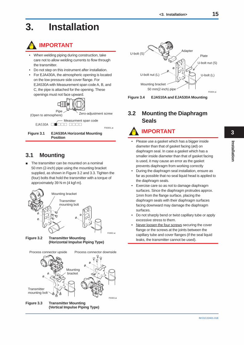
Figure 3.4 EJA510A and EJA530A Mounting
3.2 Mounting the Diaphragm Seals
IMPORTANT• Please use a gasket which has a bigger inside
diameter than that of gasket facing (ød) on diaphragm seal. In case a gasket which has a smaller inside diameter than that of gasket facing is used, it may cause an error as the gasket prevents diaphragm from working correctly
• During the diaphragm seal installation, ensure as far as possible that no seal liquid head is applied to the diaphragm seals.
• Exercise care so as not to damage diaphragm surfaces. Since the diaphragm protrudes approx. 1mm from the fl ange surface, placing the diaphragm seals with their diaphragm surfaces facing downward may damage the diaphragm surfaces.
• Do not sharply bend or twist capillary tube or apply excessive stress to them.
• Never loosen the four screws securing the cover fl ange or the screws at the joints between the capillary tube and cover fl anges (if the seal liquid leaks, the transmitter cannot be used).
Installation
3
<3. Installation> 16
IM 01C22A01-01E
3.2.1 EJA210A and EJA220AThe transmitter is mounted on a process using its high pressure side fl ange as shown in Figure 3.5. The customer should prepare the mating fl ange, gasket, stud bolts and nuts.
GasketStud bolt
NutF0305.ai
Figure 3.5 EJA210A and EJA220A Mounting
3.2.2 EJA118 and EJA438Mount the diaphragm seals using the fl anges as shown in Figure 3.6. The customer should prepare the mating fl ange, gasket, bolts and nuts.
NutFlangeDiaphragm
ødGasket
F0306.ai
Bolt
The product is shipped with these parts assembled.
Correctly install the diaphragm seals on the high and low pressure sides of the process, checking the label on each seal.
Figure 3.6 Mounting the Diaphragm Seals
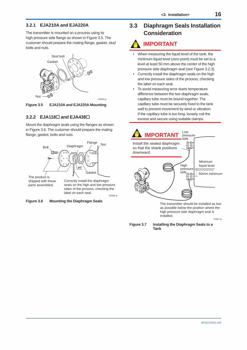
3.3 Diaphragm Seals Installation Consideration
IMPORTANT• When measuring the liquid level of the tank, the
minimum liquid level (zero point) must be set to a level at least 50 mm above the center of the high pressure side diaphragm seal (see Figure 3.2.3).
• Correctly install the diaphragm seals on the high and low pressure sides of the process, checking the label on each seal.
• To avoid measuring error duets temperature difference between the two diaphragm seals, capillary tube must be bound together. The capillary tube must be securely fi xed to the tank wall to prevent movement by wind or vibration. If the capillary tube is too long, loosely coil the excess and secure using suitable clamps.
F0307.ai
Lowpressureside
Highpressureside 50mm minimum
Minimumliquid level
Install the sealed diaphragm so that the shank positions downward.
IMPORTANT
The transmitter should be installed as low as possible below the position where the high pressure side diaphragm seal is installed.
Figure 3.7 Installing the Diaphragm Seals to a Tank
<3. Installation> 17
IM 01C22A01-01E
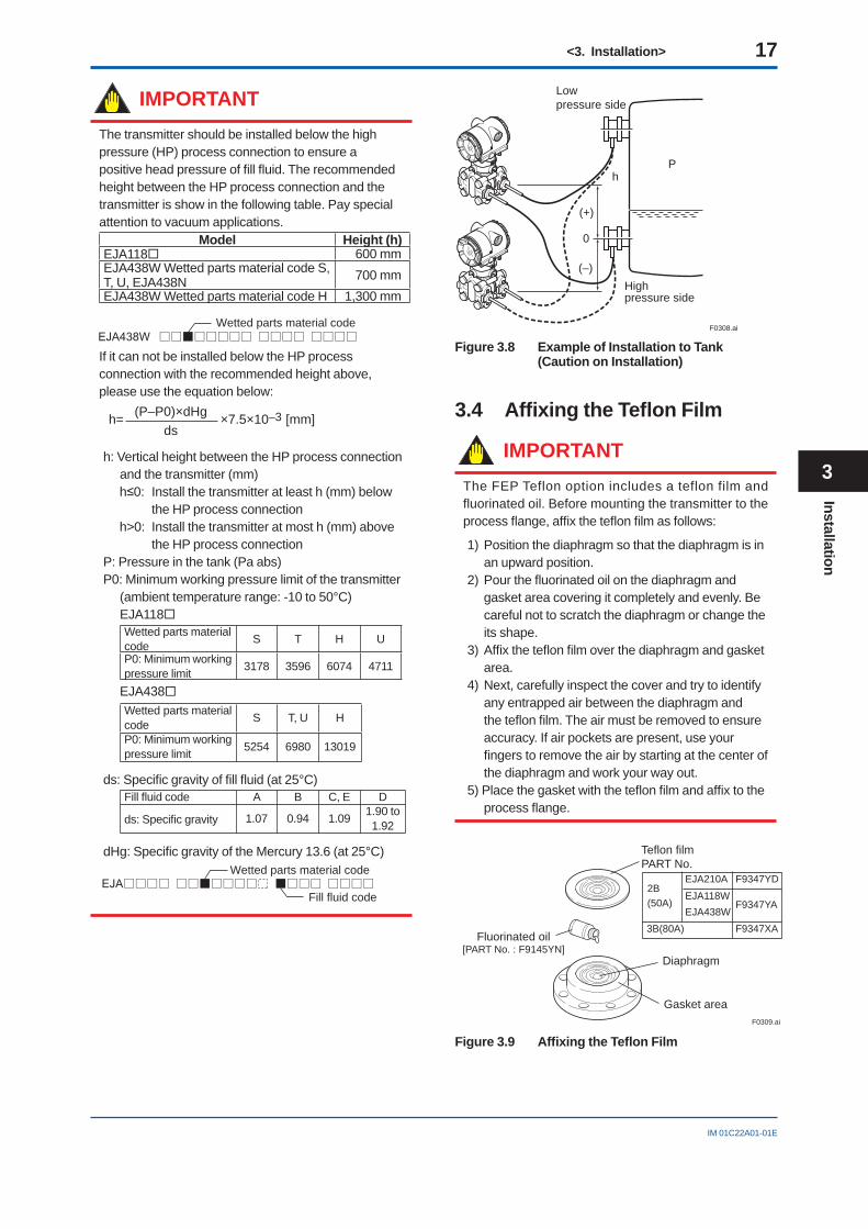
IMPORTANTThe transmitter should be installed below the high pressure (HP) process connection to ensure a positive head pressure of fi ll fl uid. The recommended height between the HP process connection and the transmitter is show in the following table. Pay special attention to vacuum applications.
Model Height (h)EJA118 600 mmEJA438W Wetted parts material code S, T, U, EJA438N 700 mmEJA438W Wetted parts material code H 1,300 mm
Wetted parts material code
If it can not be installed below the HP process connection with the recommended height above, please use the equation below:
h= ×7.5×10⁻³ [mm](P–P0)×dHgds
h: Vertical height between the HP process connection and the transmitter (mm)h≤0: Install the transmitter at least h (mm) below
the HP process connectionh>0: Install the transmitter at most h (mm) above
the HP process connectionP: Pressure in the tank (Pa abs)P0: Minimum working pressure limit of the transmitter
(ambient temperature range: -10 to 50°C)EJA118Wetted parts material code S T H U
P0: Minimum working pressure limit 3178 3596 6074 4711
EJA438Wetted parts material code S T, U H
P0: Minimum working pressure limit 5254 6980 13019
ds: Specifi c gravity of fi ll fl uid (at 25°C)Fill fl uid code A B C, E D
ds: Specifi c gravity 1.07 0.94 1.09 1.90 to 1.92
dHg: Specifi c gravity of the Mercury 13.6 (at 25°C)Wetted parts material code
Fill fluid code
F0308.ai
Ph
Lowpressure side
0
Highpressure side
(+)
(–)
Figure 3.8 Example of Installation to Tank (Caution on Installation)
3.4 Affi xing the Tefl on Film
IMPORTANTThe FEP Teflon option includes a teflon film and fluorinated oil. Before mounting the transmitter to the process fl ange, affi x the tefl on fi lm as follows:
1) Position the diaphragm so that the diaphragm is in an upward position.
2) Pour the fl uorinated oil on the diaphragm and gasket area covering it completely and evenly. Be careful not to scratch the diaphragm or change the its shape.
3) Affi x the tefl on fi lm over the diaphragm and gasket area.
4) Next, carefully inspect the cover and try to identify any entrapped air between the diaphragm and the tefl on fi lm. The air must be removed to ensure accuracy. If air pockets are present, use your fi ngers to remove the air by starting at the center of the diaphragm and work your way out.
5) Place the gasket with the tefl on fi lm and affi x to the process fl ange.
F0309.ai
EJA210A F9347YDEJA118WEJA438W
F9347YA2B(50A)
F9347XA3B(80A)
Teflon filmPART No.
Diaphragm
Fluorinated oil[PART No. : F9145YN]
Gasket area
Figure 3.9 Affi xing the Tefl on Film
Installation
3
<3. Installation> 18
IM 01C22A01-01E
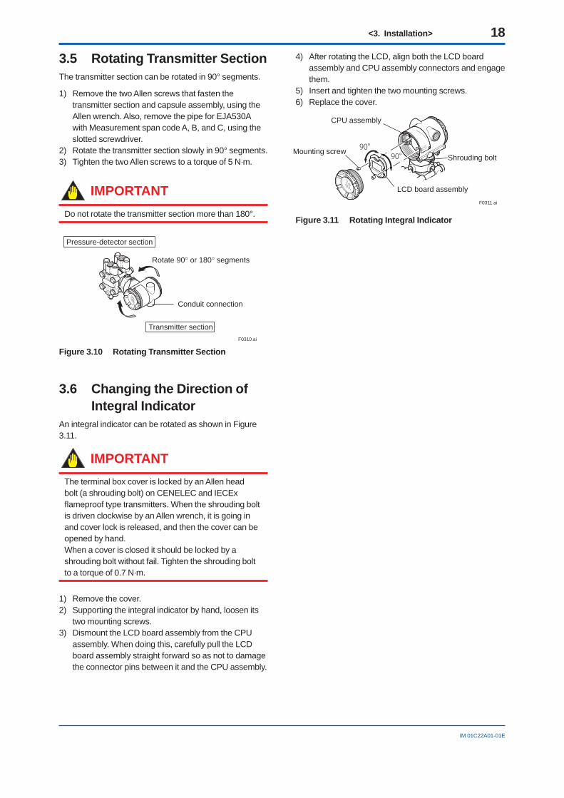
3.5 Rotating Transmitter SectionThe transmitter section can be rotated in 90° segments.
1) Remove the two Allen screws that fasten the transmitter section and capsule assembly, using the Allen wrench. Also, remove the pipe for EJA530A with Measurement span code A, B, and C, using the slotted screwdriver.
2) Rotate the transmitter section slowly in 90° segments.3) Tighten the two Allen screws to a torque of 5 N·m.
IMPORTANTDo not rotate the transmitter section more than 180°.
F0310.ai
Pressure-detector section
Transmitter section
Rotate 90 or 180 segments
Conduit connection
Figure 3.10 Rotating Transmitter Section
3.6 Changing the Direction of Integral Indicator
An integral indicator can be rotated as shown in Figure 3.11.
IMPORTANTThe terminal box cover is locked by an Allen head bolt (a shrouding bolt) on CENELEC and IECEx fl ameproof type transmitters. When the shrouding bolt is driven clockwise by an Allen wrench, it is going in and cover lock is released, and then the cover can be opened by hand.When a cover is closed it should be locked by a shrouding bolt without fail. Tighten the shrouding bolt to a torque of 0.7 N·m.
1) Remove the cover.2) Supporting the integral indicator by hand, loosen its
two mounting screws.3) Dismount the LCD board assembly from the CPU
assembly. When doing this, carefully pull the LCD board assembly straight forward so as not to damage the connector pins between it and the CPU assembly.
4) After rotating the LCD, align both the LCD board assembly and CPU assembly connectors and engage them.
5) Insert and tighten the two mounting screws.6) Replace the cover.
90°90°
F0311.ai
CPU assembly
Mounting screw
LCD board assembly
Shrouding bolt
Figure 3.11 Rotating Integral Indicator
<4. Installing Impulse Piping> 19
IM 01C22A01-01E
4. Installing Impulse Piping4.1 Impulse Piping Installation
PrecautionsThe impulse piping that connects the process outputs to the transmitter must convey the process pressure accurately. If, for example, gas collects in a liquid fi lled impulse piping, or the drain of a gas-fi lled impulse piping becomes plugged, the impulse piping will not convey the pressure accurately. Since this will cause errors in the measurement output, select the proper piping method for the process fl uid (gas, liquid, or steam). Pay careful attention to the following points when routing the impulse piping and connecting the impulse piping to the transmitter.
4.1.1 Connecting Impulse Piping to the Transmitter
(1) Check the High and Low Pressure Connections on the Transmitter (Figure 4.1)
Symbols “H” and “L” are shown on a capsule assembly to indicate high and low pressure side. Connect the impulse piping to the “H” side, and the low impulse piping to the “L” side.
F0401.ai
Pressureconnection
“H” and “L” are shown
Process connection
Process connector
Bolt
Figure 4.1 “H” and “L” Symbols on a Capsule Assembly
(2) Changing the Process Connector Piping Connections
The impulse piping connection distances can be changed between 51 mm, 54 mm and 57 mm by changing the orientation of the process connectors.This is convenient for aligning the impulse piping with the process connectors when connecting the piping.
57 mm 54 mm 51 mmF0402.ai
Figure 4.2 Process Connector Impulse Piping Connection Distances
(3) Tightening the Process Connector Mounting Bolts
After connecting the impulse piping, tighten the process connector mounting bolts uniformly.
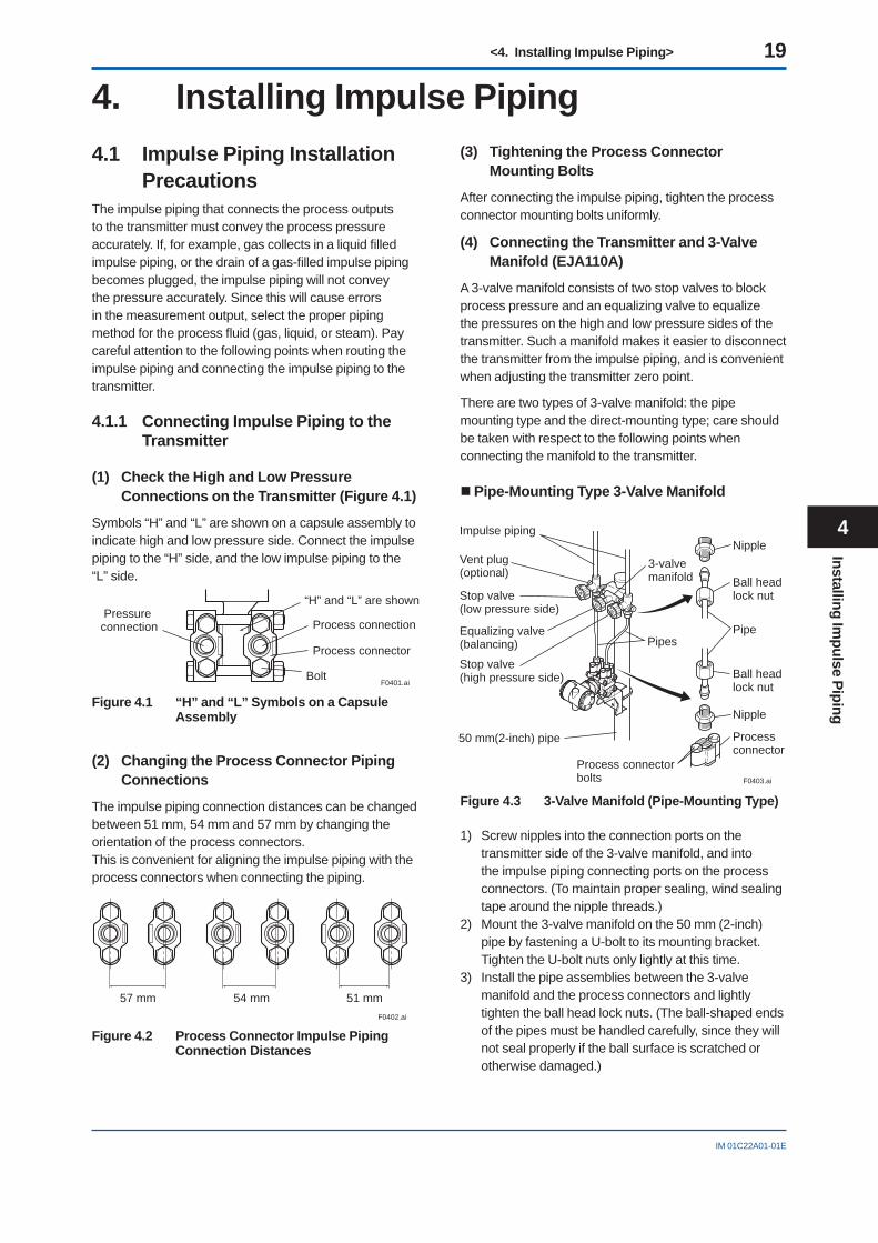
(4) Connecting the Transmitter and 3-Valve Manifold (EJA110A)
A 3-valve manifold consists of two stop valves to block process pressure and an equalizing valve to equalize the pressures on the high and low pressure sides of the transmitter. Such a manifold makes it easier to disconnect the transmitter from the impulse piping, and is convenient when adjusting the transmitter zero point.
There are two types of 3-valve manifold: the pipe mounting type and the direct-mounting type; care should be taken with respect to the following points when connecting the manifold to the transmitter.
Pipe-Mounting Type 3-Valve Manifold
F0403.ai
Nipple
Nipple
Processconnector
Ball headlock nut
Pipe
Ball headlock nut
Process connectorbolts
50 mm(2-inch) pipe
Pipes
3-valvemanifold
Impulse piping
Vent plug(optional)
Stop valve(low pressure side)
Equalizing valve(balancing)
Stop valve(high pressure side)
Figure 4.3 3-Valve Manifold (Pipe-Mounting Type)
1) Screw nipples into the connection ports on the transmitter side of the 3-valve manifold, and into the impulse piping connecting ports on the process connectors. (To maintain proper sealing, wind sealing tape around the nipple threads.)
2) Mount the 3-valve manifold on the 50 mm (2-inch) pipe by fastening a U-bolt to its mounting bracket. Tighten the U-bolt nuts only lightly at this time.
3) Install the pipe assemblies between the 3-valve manifold and the process connectors and lightly tighten the ball head lock nuts. (The ball-shaped ends of the pipes must be handled carefully, since they will not seal properly if the ball surface is scratched or otherwise damaged.)
Installing Impulse Piping
4
<4. Installing Impulse Piping> 20
IM 01C22A01-01E
4) Now tighten the nuts and bolts securely in the following sequence:Process connector bolts → transmitter-end ball head lock nuts → 3-valve manifold ball head lock nuts → 3-valve manifold mounting bracket U-bolt nuts
Direct-Mounting Type 3-Valve Manifold
1) Mount the 3-valve manifold on the transmitter. (When mounting, use the two gaskets and the four bolts provided with the 3-valve manifold. Tighten the bolts evenly.)
2) Mount the process connectors and gaskets on the top of the 3-valve manifold (the side on which the impulse piping will be connected.)
BoltsProcessconnector
Gasket
GasketProcess
connector
Bolts
Stop valve
Stop valve
3-valve manifold
3-valvemanifold
Equalizing valve
Equalizingvalve
Stop valve
Impulsepiping
Impulsepiping
Stop valve
F0404.ai
Figure 4.4 3-Valve Manifold (Direct-Mounting Type)
4.1.2 Routing the Impulse Piping
(1) Process Pressure Tap Angles
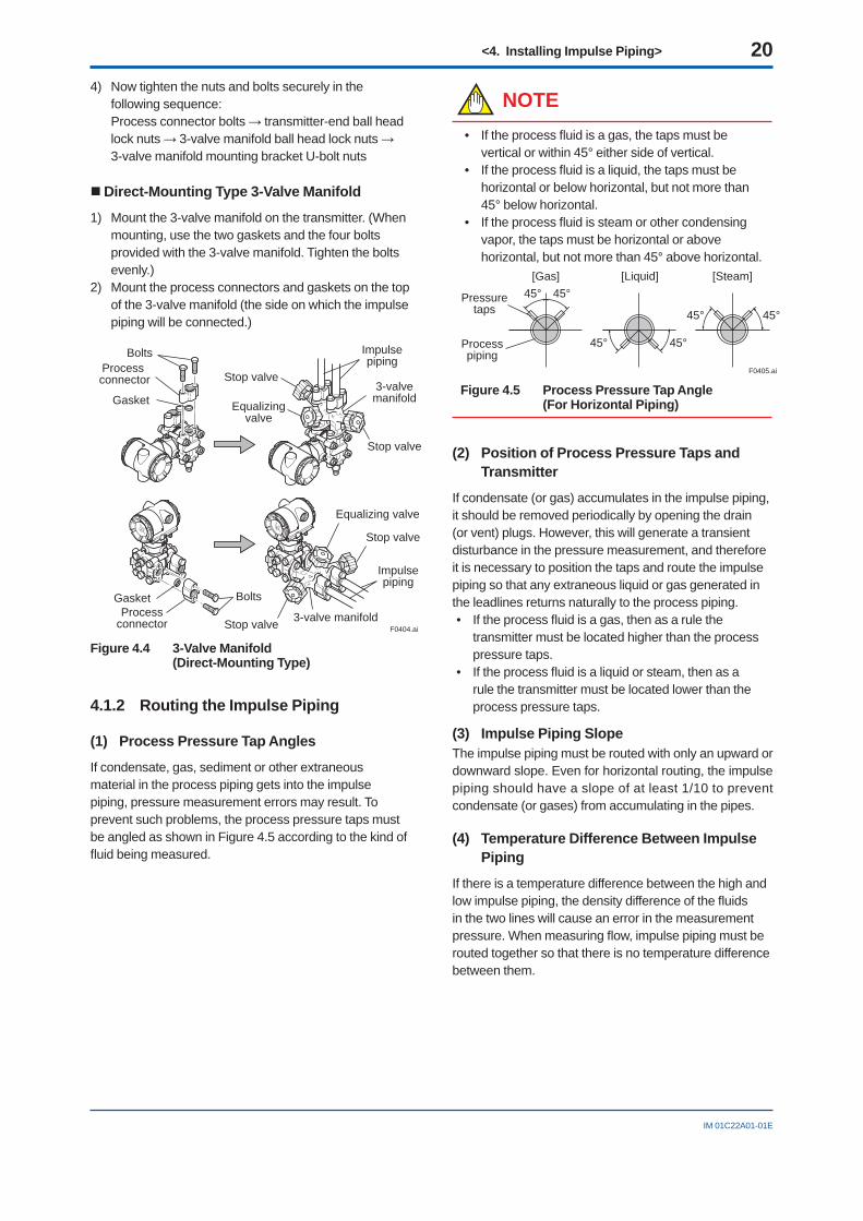
If condensate, gas, sediment or other extraneous material in the process piping gets into the impulse piping, pressure measurement errors may result. To prevent such problems, the process pressure taps must be angled as shown in Figure 4.5 according to the kind of fl uid being measured.
NOTE• If the process fl uid is a gas, the taps must be
vertical or within 45° either side of vertical.• If the process fl uid is a liquid, the taps must be
horizontal or below horizontal, but not more than 45° below horizontal.
• If the process fl uid is steam or other condensing vapor, the taps must be horizontal or above horizontal, but not more than 45° above horizontal.
[Gas]
Pressuretaps
Processpiping
[Steam][Liquid]
45°
45°
45° 45°
45°
45°
F0405.ai
Figure 4.5 Process Pressure Tap Angle (For Horizontal Piping)
(2) Position of Process Pressure Taps and Transmitter
If condensate (or gas) accumulates in the impulse piping, it should be removed periodically by opening the drain (or vent) plugs. However, this will generate a transient disturbance in the pressure measurement, and therefore it is necessary to position the taps and route the impulse piping so that any extraneous liquid or gas generated in the leadlines returns naturally to the process piping.• If the process fl uid is a gas, then as a rule the
transmitter must be located higher than the process pressure taps.
• If the process fl uid is a liquid or steam, then as a rule the transmitter must be located lower than the process pressure taps.
(3) Impulse Piping SlopeThe impulse piping must be routed with only an upward or downward slope. Even for horizontal routing, the impulse piping should have a slope of at least 1/10 to prevent condensate (or gases) from accumulating in the pipes.
(4) Temperature Difference Between Impulse Piping
If there is a temperature difference between the high and low impulse piping, the density difference of the fl uids in the two lines will cause an error in the measurement pressure. When measuring fl ow, impulse piping must be routed together so that there is no temperature difference between them.
<4. Installing Impulse Piping> 21
IM 01C22A01-01E
(5) Condensate Pots for Steam Flow Measurement
If the liquid in the impulse piping repeatedly condenses or vaporizes as a result of changes in the ambient or process temperature, this will cause a difference in the fl uid head between the high pressure and low pressure sides. To prevent measurement errors due to these head differences, condensate pots are used when measuring steam fl ow.
(6) Preventing Wind Speed Effects in Very Low Differential Pressure Measurement
IMPORTANTWhen using a differential pressure transmitter to measure very low pressures (draft pressure), the low pressure connection port is left open to atmospheric pressure (the reference pressure).Any wind around the differential pressure transmitter will therefore cause errors in the measurement. To prevent this, it will be necessary either to enclose the transmitter in a box, or to connect a impulse piping to the low pressure side and insert its end into a wind excluding pot (cylindrical with a base plate).
(7) Preventing Freezing
If there is any risk that the process fl uid in the impulse piping or transmitter could freeze, use a steam jacket or heater to maintain the temperature of the fl uid.
4.2 Impulse Piping Connection Examples
Figure 4.6, 4.7, and 4.8 shows examples of typical impulse piping connections. Before connecting the transmitter to the process, study the transmitter installation location, the process piping layout, and the characteristics of the process fl uid (corrosiveness, toxicity, fl ammability, etc.), in order to make appropriate changes and additions to the connection confi gurations.
Note the following points when referring to these piping examples.
• If the impulse piping is long, bracing or supports should be provided to prevent vibration.
• The impulse piping material used must be compatible with the process pressure, temperature, and other conditions.
• A variety of process pressure tap valves (main valves) are available according to the type of connection (fl anged, screwed, welded), construction (globe, gate, or ball valve), temperature and pressure. Select the type of valve most appropriate for the application.
Tee
3-valvemanifold
Drain valve
Orifice
Drain plug
Tap valveUnion
or flange
Liguid Gas
Condensate pot
Steam
F0406.ai
Figure 4.6 Impulse Piping Connection Examples (EJA110A)
Pipe (opened to atmosphere at low pressure side)
Open Tank Closed Tank
Tap valveUnion or flange
Vent plug
Tee
Drain valveDrain plug
F0407.ai
Figure 4.7 Impulse Piping Connection Examples (EJA210A and EJA220A)
F0408.ai
Liquid Gas Steam
Union or flange
TeeTee
Drain plug
Drain valve
Drain valveDrain plug
Union or flange
Union or flange
Union or flange
Tap valve
Tap valve
Tee
Drain valveDrain plug
Tap valve
Figure 4.8 Impulse Piping Connection Examples (EJA310A, EJA430A, and EJA440A)
Installing Impulse Piping
4
<4. Installing Impulse Piping> 22
IM 01C22A01-01E
4.3 Process Piping Installation Precautions
4.3.1 Connecting Process Piping to the Transmitter
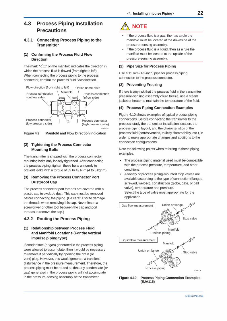
(1) Confi rming the Process Fluid Flow Direction
The mark “ ” on the manifold indicates the direction in which the process fl uid is fl owed (from right to left).When connecting the process piping to the process connector, confi rm the process fl uid fl ow direction.
F0409.ai
Flow direction (from right to left)Manifold
Orifice name plate
Process connector(low pressure side)
Process connector(high pressure side)
Process connection(outflow side)
Process connection(inflow side)
Figure 4.9 Manifold and Flow Direction Indication
(2) Tightening the Process Connector Mounting Bolts
The transmitter is shipped with the process connector mounting bolts only loosely tightened. After connecting the process piping, tighten these bolts uniformly to prevent leaks with a torque of 39 to 49 N·m {4 to 5 kgf·m}.
(3) Removing the Process Connector Port Dustproof Cap
The process connector port threads are covered with a plastic cap to exclude dust. This cap must be removed before connecting the piping. (Be careful not to damage the threads when removing this cap. Never insert a screwdriver or other tool between the cap and port threads to remove the cap.)
4.3.2 Routing the Process Piping
(1) Relationship between Process Fluid and Manifold Locations (For the vertical impulse piping type)
If condensate (or gas) generated in the process piping were allowed to accumulate, then it would be necessary to remove it periodically by opening the drain (or vent) plug. However, this would generate a transient disturbance in the pressure measurement. Therefore, the process piping must be routed so that any condensate (or gas) generated in the process piping will not accumulate in the pressure-sensing assembly of the transmitter.
NOTE• If the process fl uid is a gas, then as a rule the
manifold must be located at the downside of the pressure-sensing assembly.
• If the process fl uid is a liquid, then as a rule the manifold must be located at the upside of the pressure-sensing assembly.
(2) Pipe Size for Process Piping
Use a 15 mm (1/2-inch) pipe for process piping connection to the process connector.
(3) Preventing Freezing
If there is any risk that the process fl uid in the transmitter pressure-sensing assembly could freeze, use a steam jacket or heater to maintain the temperature of the fl uid.
(4) Process Piping Connection Examples
Figure 4.10 shows examples of typical process piping connections. Before connecting the transmitter to the process, study the transmitter installation location, the process piping layout, and the characteristics of the process fl uid (corrosiveness, toxicity, fl ammability, etc.), in order to make appropriate changes and additions to the connection confi gurations.
Note the following points when referring to these piping examples.
• The process piping material used must be compatible with the process pressure, temperature, and other conditions.
• A variety of process piping-mounted stop valves are available according to the type of connection (fl anged, screwed, welded), construction (globe, gate, or ball valve), temperature and pressure.Select the type of valve most appropriate for the application.
Gas flow measurement
Liquid flow measurement
Union or flange
Union or flange
Stop valve
Stop valve
Manifold
Manifold
Process piping
Process pipingF0410.ai
Figure 4.10 Process Piping Connection Examples (EJA115)
<5. Wiring> 23
IM 01C22A01-01E
5. Wiring
NOTEFor FOUNDATION Fieldbus and PROFIBUS PA communication types, please refer to manuals in the attached CD-ROM.
5.1 Wiring Precautions
IMPORTANT• Lay wiring as far as possible from electrical noise
sources such as large capacity transformers, motors, and power supplies.
• Remove electrical connection dust cap before wiring.
• All threaded parts must be treated with waterproofi ng sealant. (A non-hardening silicone group sealant is recommended.)
• To prevent noise pickup, do not pass signal and power cables through the same ducts.
• Explosion-protected instruments must be wired in accordance with specifi c requirements (and, in certain countries, legal regulations) in order to preserve the effectiveness of their explosion-protected features.
• The terminal box cover is locked by an Allen head bolt (a shrouding bolt) on CENELEC and IECEx fl ameproof type transmitters. When the shrouding bolt is driven clockwise by an Allen wrench, it is going in and cover lock is released, and then the cover can be opened by hand.When a cover is closed it should be locked by a shrouding bolt without fail. Tighten the shrouding bolt to a torque of 0.7 N·m.
Shrouding BoltShrouding Bolt
F0501.ai
5.2 Connections of External Wiring to Terminal Box
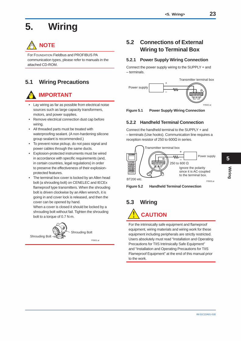
5.2.1 Power Supply Wiring ConnectionConnect the power supply wiring to the SUPPLY + and – terminals.
Power supply–
+Transmitter terminal box
F0502.ai
Figure 5.1 Power Supply Wiring Connection
5.2.2 Handheld Terminal ConnectionConnect the handheld terminal to the SUPPLY + and – terminals (Use hooks). Communication line requires a reception resistor of 250 to 600Ω in series.
Transmitter terminal box
BT200 etc.F0503.ai
Power supply–
+
Ignore the polaritysince it is AC-coupled to the terminal box.
250 to 600 Ω
Figure 5.2 Handheld Terminal Connection
5.3 Wiring
CAUTIONFor the intrinsically safe equipment and fl ameproof equipment, wiring materials and wiring work for these equipment including peripherals are strictly restricted. Users absolutely must read “Installation and Operating Precautions for TIIS Intrinsically Safe Equipment” and “Installation and Operating Precautions for TIIS Flameproof Equipment” at the end of this manual prior to the work.
Wiring
5
<5. Wiring> 24
IM 01C22A01-01E
5.3.1 Loop Confi gurationSince the DPharp uses a two-wire transmission system, signal wiring is also used as power wiring.
DC power is required for the transmitter loop. The transmitter and distributor are connected as shown below.
For details of the power supply voltage and load resistance, see Section 5.6.
(1) General-use Type and Flameproof Type
Hazardous Location Non-hazardous Location
Transmitter terminal boxDistributor(Power supply unit)
Receiverinstrument
F0504.ai–
+
Figure 5.3 Connection between Transmitter and Distributor
(2) Intrinsically Safe Type
For intrinsically safe type, a safety barrier must be included in the loop.
Hazardous Location Non-hazardous Location
Transmitter terminal boxDistributor(Power supply unit)
Receiverinstrument
Safety barrierF0505.ai
–
+
Figure 5.4 Connection between Transmitter and Distributor
5.3.2 Wiring Installation
(1) General-use Type and Intrinsically Safe Type
Make cable wiring using metallic conduit or waterproof glands.
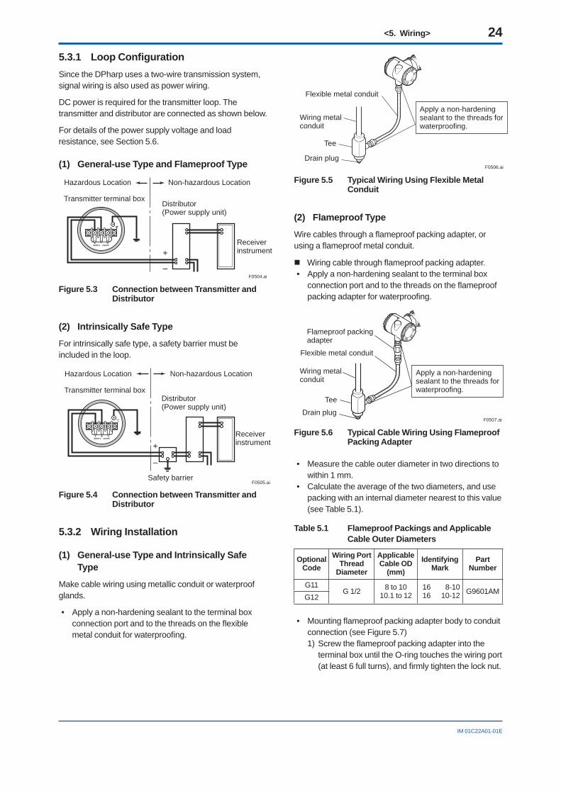
• Apply a non-hardening sealant to the terminal box connection port and to the threads on the fl exible metal conduit for waterproofi ng.
F0506.ai
Flexible metal conduit
Wiring metalconduit
Tee
Drain plug
Apply a non-hardeningsealant to the threads forwaterproofing.
Figure 5.5 Typical Wiring Using Flexible Metal Conduit
(2) Flameproof Type
Wire cables through a fl ameproof packing adapter, or using a fl ameproof metal conduit.
Wiring cable through fl ameproof packing adapter.• Apply a non-hardening sealant to the terminal box
connection port and to the threads on the fl ameproof packing adapter for waterproofi ng.
Flameproof packingadapter
Flexible metal conduit
Wiring metalconduit
Tee
Drain plug
Apply a non-hardeningsealant to the threads forwaterproofing.
F0507.ai
Figure 5.6 Typical Cable Wiring Using Flameproof Packing Adapter
• Measure the cable outer diameter in two directions to within 1 mm.
• Calculate the average of the two diameters, and use packing with an internal diameter nearest to this value (see Table 5.1).
Table 5.1 Flameproof Packings and Applicable Cable Outer Diameters
OptionalCode
Wiring PortThread
Diameter
ApplicableCable OD
(mm)Identifying
MarkPart
Number
G11G 1/2 8 to 10
10.1 to 121616
8-1010-12 G9601AM
G12
• Mounting fl ameproof packing adapter body to conduit connection (see Figure 5.7)1) Screw the fl ameproof packing adapter into the
terminal box until the O-ring touches the wiring port (at least 6 full turns), and fi rmly tighten the lock nut.
<5. Wiring> 25
IM 01C22A01-01E
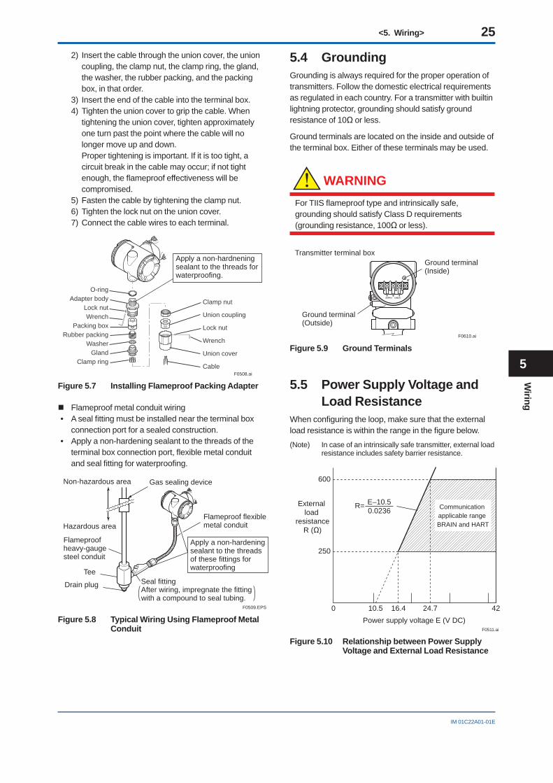
2) Insert the cable through the union cover, the union coupling, the clamp nut, the clamp ring, the gland, the washer, the rubber packing, and the packing box, in that order.
3) Insert the end of the cable into the terminal box.4) Tighten the union cover to grip the cable. When
tightening the union cover, tighten approximately one turn past the point where the cable will no longer move up and down.Proper tightening is important. If it is too tight, a circuit break in the cable may occur; if not tight enough, the fl ameproof effectiveness will be compromised.
5) Fasten the cable by tightening the clamp nut.6) Tighten the lock nut on the union cover.7) Connect the cable wires to each terminal.
O-ringAdapter body
Lock nutWrench
Packing boxRubber packing
WasherGland
Clamp ring
Clamp nut
Union coupling
Lock nut
Wrench
Union cover
Cable
Apply a non-hardneningsealant to the threads forwaterproofing.
F0508.ai
Figure 5.7 Installing Flameproof Packing Adapter
Flameproof metal conduit wiring• A seal fi tting must be installed near the terminal box
connection port for a sealed construction.• Apply a non-hardening sealant to the threads of the
terminal box connection port, fl exible metal conduit and seal fi tting for waterproofi ng.
F0509.EPS
Non-hazardous area
Hazardous area
Flameproofheavy-gaugesteel conduit
Tee
Drain plug Seal fitting
Gas sealing device
Flameproof flexible metal conduit
Apply a non-hardeningsealant to the threads of these fittings for waterproofing
After wiring, impregnate the fittingwith a compound to seal tubing.
Figure 5.8 Typical Wiring Using Flameproof Metal Conduit
5.4 GroundingGrounding is always required for the proper operation of transmitters. Follow the domestic electrical requirements as regulated in each country. For a transmitter with builtin lightning protector, grounding should satisfy ground resistance of 10Ω or less.
Ground terminals are located on the inside and outside of the terminal box. Either of these terminals may be used.
WARNING
For TIIS fl ameproof type and intrinsically safe, grounding should satisfy Class D requirements (grounding resistance, 100Ω or less).
Ground terminal(Inside)
Ground terminal(Outside)
Transmitter terminal box
F0610.ai
Figure 5.9 Ground Terminals
5.5 Power Supply Voltage and Load Resistance
When confi guring the loop, make sure that the external load resistance is within the range in the fi gure below.
(Note) In case of an intrinsically safe transmitter, external load resistance includes safety barrier resistance.
600
250
0 10.5 16.4 24.7 42
Externalload
resistanceR (Ω)
Power supply voltage E (V DC)F0511.ai
Communicationapplicable range BRAIN and HART
R= E–10.50.0236
Figure 5.10 Relationship between Power Supply Voltage and External Load Resistance
Wiring
5
<6. Operation> 26
IM 01C22A01-01E
6. Operation
NOTEFor FOUNDATION Fieldbus and PROFIBUS PA communication types and for the transmitter operating confi rmation and zeroing by any communication method, refer to manuals in the attached CD-ROM for further information.
6.1 Preparation for Starting Operation
Confi rming that Transmitter is Operating Properly
On the integral indicator
• If the wiring system is faulty, the display stays blank.• If the transmitter is faulty, an error code will appear on
the display according to the nature of the error.
Self-diagnostic error on the integral indicator(Faulty transmitter) F0601.ai
NOTEIf any of the error indications above appears on the display of the integral indicator, refer to Chapter 7 for corrective action.
Verify and Change Transmitter Parameter Setting and Values
The following parameters are the minimum settings required for operation.
• Measuring range• Output/integral indicator mode• Operation mode
Output Status Setting at CPU Failure
Set the burn-out direction as shown in the fi gures below. The direction is set to the H side for delivery unless option code /C1 is specifi ed in the order. For option code /F1, the output signal for down-scale is -2.5%, 3.6 mA DC or less.
● BRAIN and HART except option code /F1
Setting pin (CN4)
CPU assembly
H L
H L
Burn-OutDirection
HIGH
Output atBurn-Out
Setting Pin (CN4)Position
-5% or lower
110% or higher
LOW
F0602.ai
Figure 6.1 Burn-out Direction Setting Pin
● HART with option code /F1
CPU assembly
Slide switch Burn-out direction switch
Write protection switch
L HY N
Write ProtectionSwitch Position
L HY N
L HY N
Write Protection
Hardware write protection switch
YESNO
HIGH LOW
Burnout DirectionSwitch Position
L HY N
L HY N
Burn-out direction switch
Burn-out Direction
F0603.ai
Figure 6.2 Burn-out Direction Slide Switch
<6. Operation> 27
IM 01C22A01-01E
6.2 Zero Point AdjustmentAdjust the zero point after operating preparation is completed.
IMPORTANTDo not turn off the power to the transmitter immediately after a zero adjustment. Powering off within 30 seconds after a zero adjustment will return the adjustment back to the previous settings.
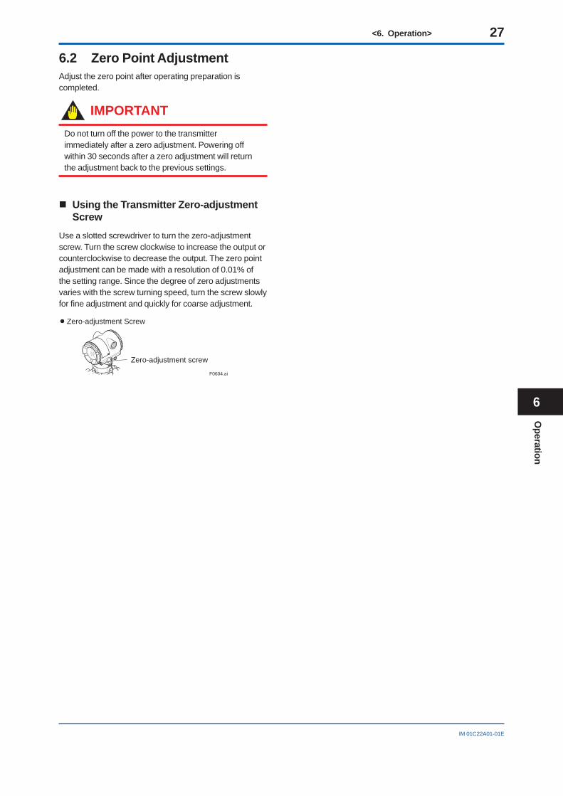
Using the Transmitter Zero-adjustment Screw
Use a slotted screwdriver to turn the zero-adjustment screw. Turn the screw clockwise to increase the output or counterclockwise to decrease the output. The zero point adjustment can be made with a resolution of 0.01% of the setting range. Since the degree of zero adjustments varies with the screw turning speed, turn the screw slowly for fi ne adjustment and quickly for coarse adjustment.
F0604.ai
Zero-adjustment screw
Zero-adjustment Screw
Operation
6
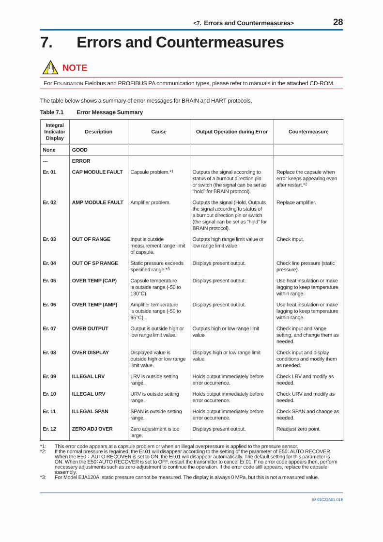
<7. Errors and Countermeasures> 28
IM 01C22A01-01E
7. Errors and CountermeasuresNOTE
For FOUNDATION Fieldbus and PROFIBUS PA communication types, please refer to manuals in the attached CD-ROM.
The table below shows a summary of error messages for BRAIN and HART protocols.
Table 7.1 Error Message Summary
Integral Indicator Display
Description Cause Output Operation during Error Countermeasure
None GOOD
--- ERROR
Er. 01 CAP MODULE FAULT Capsule problem.*1 Outputs the signal according to status of a burnout direction pin or switch (the signal can be set as “hold” for BRAIN protocol).
Replace the capsule when error keeps appearing even after restart.*2
Er. 02 AMP MODULE FAULT Amplifi er problem. Outputs the signal (Hold, Outputs the signal according to status of a burnout direction pin or switch (the signal can be set as “hold” for BRAIN protocol).
Replace amplifi er.
Er. 03 OUT OF RANGE Input is outside measurement range limit of capsule.
Outputs high range limit value or low range limit value.
Check input.
Er. 04 OUT OF SP RANGE Static pressure exceeds specifi ed range.*3
Displays present output. Check line pressure (static pressure).
Er. 05 OVER TEMP (CAP) Capsule temperature is outside range (-50 to 130°C).
Displays present output. Use heat insulation or make lagging to keep temperature within range.
Er. 06 OVER TEMP (AMP) Amplifi er temperature is outside range (-50 to 95°C).
Displays present output. Use heat insulation or make lagging to keep temperature within range.
Er. 07 OVER OUTPUT Output is outside high or low range limit value.
Outputs high or low range limit value.
Check input and range setting, and change them as needed.
Er. 08 OVER DISPLAY Displayed value is outside high or low range limit value.
Displays high or low range limit value.
Check input and display conditions and modify them as needed.
Er. 09 ILLEGAL LRV LRV is outside setting range.
Holds output immediately before error occurrence.
Check LRV and modify as needed.
Er. 10 ILLEGAL URV URV is outside setting range.
Holds output immediately before error occurrence.
Check URV and modify as needed.
Er. 11 ILLEGAL SPAN SPAN is outside setting range.
Holds output immediately before error occurrence.
Check SPAN and change as needed.
Er. 12 ZERO ADJ OVER Zero adjustment is too large.
Displays present output. Readjust zero point.
*1: This error code appears at a capsule problem or when an illegal overpressure is applied to the pressure sensor. *2: If the normal pressure is regained, the Er.01 will disappear according to the setting of the parameter of E50:AUTO RECOVER.
When the E50:AUTO RECOVER is set to ON, the Er.01 will disappear automatically. The default setting for this parameter is ON. When the E50:AUTO RECOVER is set to OFF, restart the transmitter to cancel Er.01. If no error code appears then, perform necessary adjustments such as zero-adjustment to continue the operation. If the error code still appears, replace the capsule assembly.
*3: For Model EJA120A, static pressure cannot be measured. The display is always 0 MPa, but this is not a measured value.
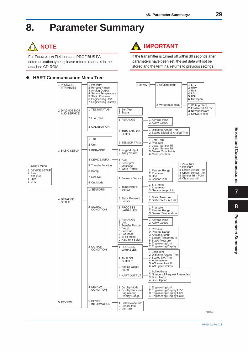
<8. Parameter Summary> 29
IM 01C22A01-01E
8. Parameter Summary
NOTEFor FOUNDATION Fieldbus and PROFIBUS PA communication types, please refer to manuals in the attached CD-ROM.
IMPORTANTIf the transmitter is turned off within 30 seconds after parameters have been set, the set data will not be stored and the terminal returns to previous settings.
HART Communication Menu Tree
1 DEVICE SETUP 2 Pres 3 A01 Out 4 LRV 5 URV
Online Menu
1 PROCESS VARIABLES
2 DIAGNOSTICS AND SERVICE
3 BASIC SETUP
4 DETAILED SETUP
5 REVIEW
1 Pressure 2 Percent Range 3 Analog Output 4 Sensor Temperature 5 Static Pressure 6 Engineering Unit 7 Engineering Display
1 TEST/STATUS
2 Loop Test
3 CALIBRATION
1 Self Test 2 Status
1 Keypad Input
2 Wrt protect menu
Hot Key 1 LRV 2 URV 3 Unit 4 LSL 5 USL 6 Min Span
1 Tag
2 Unit
3 RERANGE
4 DEVICE INFO
5 Transfer Function
6 Damp
7 Low Cut
8 Cut Mode
1 Keypad Input 2 Apply Values
1 Date 2 Descriptor 3 Message 4 Write Protect
1 SENSORS
2 SIGNAL CONDITION
3 OUTPUT CONDITION
4 DISPLAY CONDITION
5 DEVICE INFORMATION
1 Pressure Sensor
2 Temperature Sensor
3 Static Pressure Sensor
1 Percent Range 2 Pressure 3 Unit 4 Sensor Trim
1 Zero Trim2 Pressure3 Lower Sensor Trim4 Upper Sensor Trim5 Sensor Trim Point6 Clear snsr trim
1 Snsr temp2 Amp temp3 Sensor temp Unit
1 Static Pressure 2 Static Pressure Unit
1 PROCESS VARIABLES
2 RERANGE 3 Unit 4 Transfer Function 5 Damp 6 Low Cut 7 Cut Mode 8 Bi-dir Mode 9 H2O Unit Select
1 PROCESS VARIABLES
2 ANALOG OUTPUT
3 Analog Output Alarm
4 HART OUTPUT
1 Display Mode 2 Display Function 3 Engineering Display Range
1 Field Device Info 2 Sensor Info 3 Self Test
1 Engineering Unit 2 Engineering Display LRV 3 Engineering Display URV 4 Engineering Display Point
1 Pressure2 Percent Range3 Analog Output4 Sensor Temperature5 Static Pressure6 Engineering Unit7 Engineering Display
1 Loop Test2 Digital-to-Analog Trim3 Scaled D/A Trim4 Auto recover5 AO lower limit %6 AO upper limit %
1 Poll Address 2 Number of Request Preambles 3 Burst Mode 4 Burst Option
1 Pressure 2 Percent Range 3 Sensor Temperature
1 Keypad Input 2 Apply Values
1 RERANGE
2 TRIM ANALOG OUTPUT
3 SENSOR TRIM
1 Keypad Input 2 Apply Values
1 Digital-to-Analog Trim 2 Scaled Digital-to-Analog Trim
1 Zero Trim2 Pressure3 Lower Sensor Trim4 Upper Sensor Trim5 Sensor Trim Points6 Clear snsr trim
F0801.ai
1 Write protect2 Enable wrt 10 min3 New password4 Software seal
Errors and Counterm
easures
7
Parameter Sum
mary
8
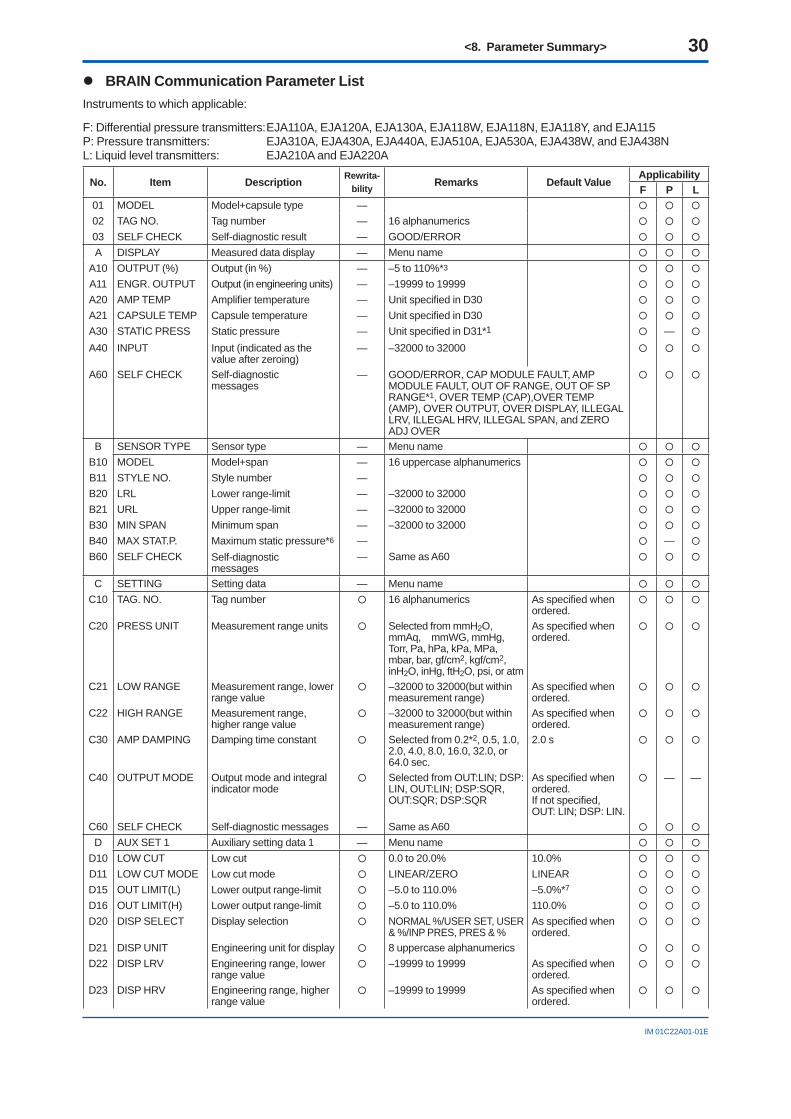
<8. Parameter Summary> 30
IM 01C22A01-01E
BRAIN Communication Parameter ListInstruments to which applicable:
F: Differential pressure transmitters: EJA110A, EJA120A, EJA130A, EJA118W, EJA118N, EJA118Y, and EJA115P: Pressure transmitters: EJA310A, EJA430A, EJA440A, EJA510A, EJA530A, EJA438W, and EJA438NL: Liquid level transmitters: EJA210A and EJA220A
No. Item Description Rewrita-bility Remarks Default Value
ApplicabilityF P L
01 MODEL Model+capsule type —
02 TAG NO. Tag number — 16 alphanumerics
03 SELF CHECK Self-diagnostic result — GOOD/ERROR
A DISPLAY Measured data display — Menu name
A10 OUTPUT (%) Output (in %) — –5 to 110%*3
A11 ENGR. OUTPUT Output (in engineering units) — –19999 to 19999
A20 AMP TEMP Amplifi er temperature — Unit specifi ed in D30
A21 CAPSULE TEMP Capsule temperature — Unit specifi ed in D30
A30 STATIC PRESS Static pressure — Unit specifi ed in D31*1 —
A40 INPUT Input (indicated as the value after zeroing)
— –32000 to 32000
A60 SELF CHECK Self-diagnosticmessages
— GOOD/ERROR, CAP MODULE FAULT, AMP MODULE FAULT, OUT OF RANGE, OUT OF SP RANGE*1, OVER TEMP (CAP),OVER TEMP (AMP), OVER OUTPUT, OVER DISPLAY, ILLEGAL LRV, ILLEGAL HRV, ILLEGAL SPAN, and ZERO ADJ OVER
B SENSOR TYPE Sensor type — Menu name
B10 MODEL Model+span — 16 uppercase alphanumerics
B11 STYLE NO. Style number —
B20 LRL Lower range-limit — –32000 to 32000
B21 URL Upper range-limit — –32000 to 32000
B30 MIN SPAN Minimum span — –32000 to 32000
B40 MAX STAT.P. Maximum static pressure*6 — —
B60 SELF CHECK Self-diagnostic messages
— Same as A60
C SETTING Setting data — Menu name
C10 TAG. NO. Tag number 16 alphanumerics As specifi ed when ordered.
C20 PRESS UNIT Measurement range units Selected from mmH2O, mmAq, mmWG, mmHg, Torr, Pa, hPa, kPa, MPa, mbar, bar, gf/cm2, kgf/cm2, inH2O, inHg, ftH2O, psi, or atm
As specifi ed when ordered.
C21 LOW RANGE Measurement range, lower range value
–32000 to 32000(but within measurement range)
As specifi ed when ordered.
C22 HIGH RANGE Measurement range, higher range value
–32000 to 32000(but within measurement range)
As specifi ed when ordered.
C30 AMP DAMPING Damping time constant Selected from 0.2*2, 0.5, 1.0, 2.0, 4.0, 8.0, 16.0, 32.0, or 64.0 sec.
2.0 s
C40 OUTPUT MODE Output mode and integral indicator mode
Selected from OUT:LIN; DSP:LIN, OUT:LIN; DSP:SQR, OUT:SQR; DSP:SQR
As specifi ed when ordered.If not specifi ed,OUT: LIN; DSP: LIN.
— —
C60 SELF CHECK Self-diagnostic messages — Same as A60
D AUX SET 1 Auxiliary setting data 1 — Menu name
D10 LOW CUT Low cut 0.0 to 20.0% 10.0%
D11 LOW CUT MODE Low cut mode LINEAR/ZERO LINEAR
D15 OUT LIMIT(L) Lower output range-limit –5.0 to 110.0% –5.0%*7
D16 OUT LIMIT(H) Lower output range-limit –5.0 to 110.0% 110.0%
D20 DISP SELECT Display selection NORMAL %/USER SET, USER & %/INP PRES, PRES & %
As specifi ed when ordered.
D21 DISP UNIT Engineering unit for display 8 uppercase alphanumerics
D22 DISP LRV Engineering range, lower range value
–19999 to 19999 As specifi ed when ordered.
D23 DISP HRV Engineering range, higher range value
–19999 to 19999 As specifi ed when ordered.
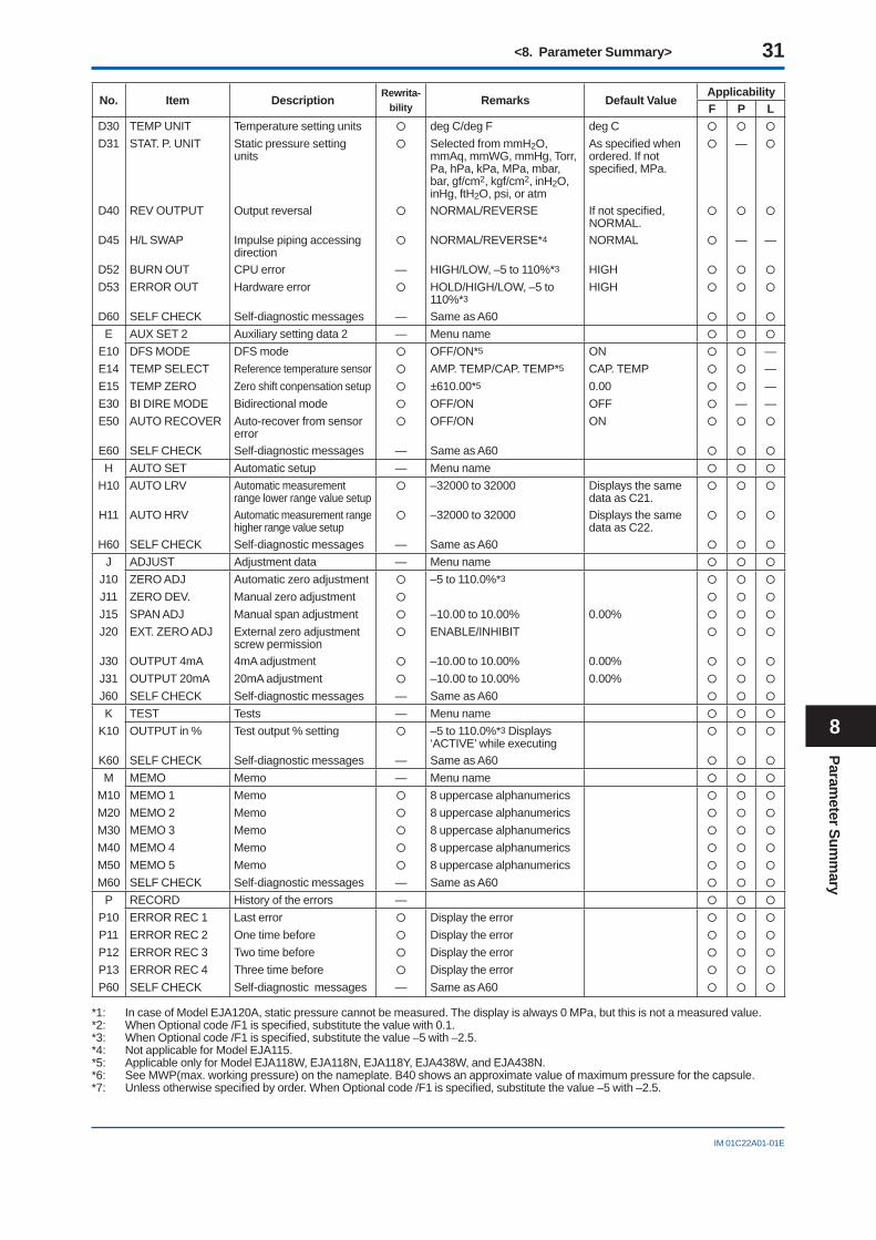
<8. Parameter Summary> 31
IM 01C22A01-01E
No. Item Description Rewrita-bility Remarks Default Value
ApplicabilityF P L
D30 TEMP UNIT Temperature setting units deg C/deg F deg C
D31 STAT. P. UNIT Static pressure setting units
Selected from mmH2O, mmAq, mmWG, mmHg, Torr, Pa, hPa, kPa, MPa, mbar, bar, gf/cm2, kgf/cm2, inH2O, inHg, ftH2O, psi, or atm
As specifi ed when ordered. If not specifi ed, MPa.
—
D40 REV OUTPUT Output reversal NORMAL/REVERSE If not specifi ed, NORMAL.
D45 H/L SWAP Impulse piping accessing direction
NORMAL/REVERSE*4 NORMAL — —
D52 BURN OUT CPU error — HIGH/LOW, –5 to 110%*3 HIGH
D53 ERROR OUT Hardware error HOLD/HIGH/LOW, –5 to 110%*3
HIGH
D60 SELF CHECK Self-diagnostic messages — Same as A60
E AUX SET 2 Auxiliary setting data 2 — Menu name
E10 DFS MODE DFS mode OFF/ON*5 ON —E14 TEMP SELECT Reference temperature sensor AMP. TEMP/CAP. TEMP*5 CAP. TEMP —E15 TEMP ZERO Zero shift conpensation setup ±610.00*5 0.00 —E30 BI DIRE MODE Bidirectional mode OFF/ON OFF — —E50 AUTO RECOVER Auto-recover from sensor
error OFF/ON ON
E60 SELF CHECK Self-diagnostic messages — Same as A60
H AUTO SET Automatic setup — Menu name
H10 AUTO LRV Automatic measurement range lower range value setup
–32000 to 32000 Displays the same data as C21.
H11 AUTO HRV Automatic measurement range higher range value setup
–32000 to 32000 Displays the same data as C22.
H60 SELF CHECK Self-diagnostic messages — Same as A60
J ADJUST Adjustment data — Menu name
J10 ZERO ADJ Automatic zero adjustment –5 to 110.0%*3
J11 ZERO DEV. Manual zero adjustment
J15 SPAN ADJ Manual span adjustment –10.00 to 10.00% 0.00%
J20 EXT. ZERO ADJ External zero adjustment screw permission
ENABLE/INHIBIT
J30 OUTPUT 4mA 4mA adjustment –10.00 to 10.00% 0.00%
J31 OUTPUT 20mA 20mA adjustment –10.00 to 10.00% 0.00%
J60 SELF CHECK Self-diagnostic messages — Same as A60
K TEST Tests — Menu name
K10 OUTPUT in % Test output % setting –5 to 110.0%*3 Displays ‘ACTIVE’ while executing
K60 SELF CHECK Self-diagnostic messages — Same as A60
M MEMO Memo — Menu name
M10 MEMO 1 Memo 8 uppercase alphanumerics
M20 MEMO 2 Memo 8 uppercase alphanumerics
M30 MEMO 3 Memo 8 uppercase alphanumerics
M40 MEMO 4 Memo 8 uppercase alphanumerics
M50 MEMO 5 Memo 8 uppercase alphanumerics
M60 SELF CHECK Self-diagnostic messages — Same as A60
P RECORD History of the errors —
P10 ERROR REC 1 Last error Display the error
P11 ERROR REC 2 One time before Display the error
P12 ERROR REC 3 Two time before Display the error
P13 ERROR REC 4 Three time before Display the error
P60 SELF CHECK Self-diagnostic messages — Same as A60
*1: In case of Model EJA120A, static pressure cannot be measured. The display is always 0 MPa, but this is not a measured value.*2: When Optional code /F1 is specifi ed, substitute the value with 0.1.*3: When Optional code /F1 is specifi ed, substitute the value –5 with –2.5.*4: Not applicable for Model EJA115.*5: Applicable only for Model EJA118W, EJA118N, EJA118Y, EJA438W, and EJA438N.*6: See MWP(max. working pressure) on the nameplate. B40 shows an approximate value of maximum pressure for the capsule.*7: Unless otherwise specifi ed by order. When Optional code /F1 is specifi ed, substitute the value –5 with –2.5.
Parameter Sum
mary
8
<Installation and Operating Precautions for TIIS Intrinsically Safe Equipment> 32
EX-A03E
Installation and Operating Precautions for TIIS Intrinsically Safe EquipmentApparatus Certifi ed Under Technical Criteria (IEC-compatible Standards) and from
“RECOMMENDED PRACTICES for Explosion-Protected Electrical Installations in General Industries,” published in 1979
1. GeneralThe following describes precautions on electrical apparatus of intrinsically safe construction (hereinafter referred to as intrinsically safe apparatus).Following the Labor Safety and Health Laws of Japan, an intrinsically safe apparatus must undergo type tests in order to be certifi ed by the Technical Institute of Industrial Safety, Inc. These tests are required to satisfy either the technical criteria for electrical machinery and equipment in compliance with explosionproof standards involving infl ammable gases or vapors and for machinery and equipment having explosionproof performance (standards notifi cation no. 556 from the Japanese Ministry of Labor) (hereinafter referred to as technical criteria), in conformity with IEC Standards, or the “Recommended Practice for Explosion-Protected Electrical Installations in General Industries,” published in 1979. Such a certifi ed apparatus can be used in hazardous locations where infl ammable gases or vapors may be present. Certifi ed apparatus includes a certifi cation label and an equipment nameplate with the specifi cations necessary for explosion requirements as well as precautions on explosion protection. Please confi rm these precautionary items and use them to meet specifi cation requirements.For electrical wiring and maintenance servicing, please refer to “Internal Wiring Rules” in the Electrical Installation Technical Standards as well as “USER’S GUIDELINES for Electrical Installations for Explosive Gas Atmospheres in General Industry,” published in 1994.To meet intrinsically safe requirements, equipment that can be termed an “intrinsically safe apparatus” must:(1) be certifi ed by the Technical Institute of Industrial Safety,
Inc. in accordance with the Labor Safety and Health Laws of Japan and have the appropriate mark of certifi cation labeled on its case, and
(2) be used in compliance with the specifi cations marked on its certifi cation label, equipment nameplate and precautionary information furnished.
Note: Intrinsically safe apparatus satisfy their performance under specifi c conditions. They are not always absolutely safe under every operational and environmental condition. In other words, they are not safe products involved with factors such as chemical reactions, geographical changes or the like other than affected by electric energy from the equipment itself.
2. Electrical Apparatus of Intrinsic Safety Type of Explosion-Protected Construction
The intrinsic safety type of explosion-protected construction is a method of protection applicable to a circuit or part of a circuit in which, under prescribed test conditions, no spark or thermal effect, whether produced normally or accidentally, is capable of causing a prescribed explosive gas to ignite. In other words, electrical apparatus of this construction is intended to suppress electrical energy thereby preventing ignition of a given explosive gas atmosphere even though spark or high thermal effect occurs in the electric circuitry.Intrinsically safe electrical apparatus generally comprise intrinsically safe apparatus installed in a hazardous location and a safety barrier (associated apparatus), installed in a non-hazardous location, aimed at preventing electrical energy from fl owing into the electric circuitry of intrinsically safe apparatus.However, battery-operated, portable intrinsically safe apparatus or the like may be used alone.
3. Terminology(1) Intrinsically safe apparatus: Electrical apparatus in which all
the circuits are intrinsically safe circuits.(2) Associated apparatus: Electrical apparatus in which there
are both intrinsically safe circuits and non-intrinsically safe circuits that can affect the safety of intrinsically safe circuits.
(3) Safety barrier: A specifi c type of associated apparatus, which consists mainly of safety barrier elements, and serves to limit the fl ow of excessive electrical energy, which is capable of causing ignition of a given explosive gas or vapour of a non-intrinsically safe circuit into concerned intrinsically safe circuits.
(4) Apparatus of category “ia”: Intrinsically safe electrical apparatus and associated apparatus which are incapable of causing ignition of a given explosive gas or vapour with the appropriate safety factors such as:- when up to two countable faults are applied and, in
addition, - when non-countable faults produce an onerous condition.
(5) Apparatus of category “ib”: Intrinsically safe electrical apparatus and associated apparatus which are incapable of causing ignition of a given explosive gas or vapour, with the appropriate safety factors such as:- when up to one countable fault is applied and, in addition,- when non-countable faults produce an onerous condition.
(6) Safety rating: A rating to be designated to intrinsically safe apparatus as well as associated apparatus and is the maximum rating allowable for maintaining intrinsic safety of concerned intrinsically safe circuits.
4. Caution on Combining Intrinsically Safe Apparatus and Safety Barriers
(1) A combination of certifi ed intrinsically safe apparatus and safety barriers needs to satisfy combination requirements. If intrinsically safe apparatus specify safety barriers for combination, safety barriers other than specifi ed cannot be used (see Note 1 for more details).
(2) Certifi ed intrinsically safe systems specify specifi c safety barriers in combination with intrinsically safe apparatus. So safety barriers other than specifi ed cannot be used (see Note 2 for more details).
(3) Other than limitations of combining intrinsically safe apparatus and safety barriers as given in (1) and (2) above, two or more pieces of apparatus certifi ed under different standards cannot be combined with each other (see Note 3 for more details). In addition, bear in mind that classifi cations of explosion protection such as “IIA,” “IIB” and “IIC” and category “ia” and “ib” limit a combination of intrinsically safe apparatus and safety barriers.
For more details, see the “Type Certifi cate Guide for Explosion-Protected Construction for Electrical Machinery and Equipment,” issued by the Japanese Ministry of Labour, the Research Institute of Industrial Safety.
Note 1: Testing ApparatusIntrinsically safe apparatus and safety barriers are assessed individually to ensure that their safety requirements are satisfi ed. Tested and certifi ed intrinsically safe apparatus and safety barriers incorporate individual certifi cation numbers.A combination of intrinsically safe apparatus and safety barriers involves the following two limitations:
<Installation and Operating Precautions for TIIS Intrinsically Safe Equipment> 33
EX-A03E
(1) A safety barrier which meets the combination requirements by referring to its safety rating and combination parameters shall be selected.
(2) For pressure transmitters, pH transmitters, temperature detectors and the like, safety barriers that can be combined are already specifi ed. Other safety barriers cannot be used.
Note 2: Testing Intrinsically Safe SystemAn assembly (as a system) in which intrinsically safe apparatus and safety barriers are combined is assessed to ensure that its safety requirements are satisfi ed. A tested and certifi ed system incorporates a certifi cation number (intrinsically safe apparatus and safety barriers have the same certifi cation number).
Note 3: Impossible Combinations of Apparatus Certifi ed Under Different StandardsIntrinsically safe apparatus certifi ed under technical criteria and safety barriers certifi ed under the “Recommended Practice for Explosion-Protected Electrical Installations in General Industries” (1979) and vice versa cannot be combined even if their combination requirements are satisfi ed.
5. Installation of Intrinsically Safe Apparatus and Safety Barriers
(1) Classifi cation of installation locationIntrinsically safe apparatus may be installed, depending upon applicable gases, in a hazardous area in Zone 0, 1 or 2 (Note 4 below), where the specifi ed gases are present. However, note that apparatus certifi ed under Technical Criteria, in category “ib” shall be installed only in Zone 1 or 2. Safety barriers (associated apparatus) that are combined with these intrinsically safe apparatus shall be installed only in a non-hazardous area. In cases where safety barriers are installed in a hazardous area, they shall be enclosed, for example, in a fl ameproof enclosure.Note 4: Hazardous areas are classifi ed in zones based upon the
frequency of the appearance and the duration of an explosive gas atmosphere as follows:Zone 0: An area in which an explosive gas atmosphere is
present continuously or is present for long periods.Zone 1: An area in which an explosive gas atmosphere is likely
to occur in normal operation.Zone 2: An area in which an explosive gas atmosphere is not
likely to occur in normal operation and if it does occur it will exist for a short period only.
(2) Ambient temperature limits for intrinsically safe apparatus
Intrinsically safe apparatus shall be installed in a location where the ambient temperature ranges from –20° to +40°C (for those certifi ed under Technical Criteria) or –10° to +40°C (for those certifi ed under the “Recommended Practice for Explosion-Protected Electrical Installations in General Industries” (1979). However, some fi eld-mounted intrinsically safe apparatus may be used at an ambient temperature up to 60°C. So, specifi cations should be checked before installing intrinsically safe apparatus.If the intrinsically safe apparatus are exposed to direct sunshine or radiant heat from plant facilities, appropriate thermal protection measures shall be taken.
6. Wiring for Intrinsically Safe CircuitsIn intrinsically safe construction, safety shall be maintained as an intrinsically safe system involving intrinsically safe apparatus and safety barriers connected thereto, and electrical wiring (through intrinsically safe circuits) interconnected between them. In other words, even when safety requirements are maintained individually by intrinsically safe apparatus and safety barriers, they shall not be affected by electrical or magnetic energy caused by electrical wiring.To make electrical wiring for intrinsically safe circuits, you must:
(a) refer to the equipment confi guration diagram and make electrical wiring properly;
(b) prevent intrinsically safe wiring from being contacted with non-intrinsically safe wiring, and separate the intrinsically safe circuit from other electrical circuits;
(c) prevent intrinsically safe wiring from being electrostatically and magnetically affected by non-intrinsically safe wiring;
(d) reduce wiring inductance and capacitance produced between the intrinsically safe apparatus and safety barrier where possible, and use a shorter cable between the intrinsically safe apparatus and safety barrier than specifi ed if the maximum permissible inductance of the cable is specifi ed as operating conditions;
(e) conform to conditions of installation such as wiring method, earthing or the like, if any; and
(f) protect the outer sheath of cables from damage with appropriate measures.
7. Maintenance and Inspection of Intrinsically Safe Apparatus and Safety Barriers
Maintenance and inspection of intrinsically safe apparatus and safety barriers shall be limited to within the instructions described in applicable instruction manuals. If other than this is required, contact the manufacturers. For more information, refer to the “USER’S GUIDELINES for Electrical Installations for Explosive Gas Atmospheres in General Industry” issued in 1994 by the Japanese Ministry of Labour, the Research Institute of Industrial Safety.
(1) Requirements for maintenance personnelMaintenance and inspection of intrinsically safe apparatus and safety barriers shall be conducted by maintenance personnel skilled in intrinsically safe construction and installation of electrical devices as well as capable of applying associated rules.
(2) Maintenance and Inspection(a) Visual inspection
Visually inspect the external connections of intrinsically safe apparatus and safety barriers, and cables for damage or corrosion as well as other mechanical and structural defects.
(b) AdjustmentsZero, span and sensitivity adjustments shall be made with applicable adjusting potentiometers and mechanical adjustment screws.These maintenance adjustments shall be made in a non-hazardous location.
CAUTIONIf intrinsically safe apparatus and safety barriers require maintenance service and checking, a gas detector shall be used to ensure that there is no explosive gas in the location (maintenance servicing shall be conducted in a non-hazardous location).
(3) RepairIntrinsically safe apparatus and safety barriers shall be repaired by manufacturers.
(4) Prohibition of modifi cations and specifi cation changes
Do not attempt to make modifi cations or change specifi cations which may affect safety.
<Installation and Operating Precautions for TIIS Flameproof Equipment> 34
EX-B03E
Installation and Operating Precautions for TIIS Flameproof EquipmentApparatus Certifi ed Under Technical Criteria (IEC-compatible Standards)
1. GeneralThe following describes precautions on electrical apparatus of fl ameproof construction (hereinafter referred to as fl ameproof apparatus) in explosion-protected apparatus.Following the Labour Safety and Health Laws of Japan, fl ameproof apparatus is subjected to type tests to meet either the technical criteria for explosionproof electrical machinery and equipment (standards notifi cation no. 556 from the Japanese Ministry of Labour) (hereinafter referred to as technical criteria), in conformity with the IEC Standards, or the “Recommended Practice for Explosion-Protected Electrical Installations in General Industries,” published in 1979. These certifi ed apparatus can be used in hazardous locations where explosive or infl ammable gases or vapours may be present.Certifi ed apparatus includes a certifi cation label and an equipment nameplate with the specifi cations necessary for explosion requirements as well as precautions on explosion protection. Please confi rm these precautionary items and use them to meet specifi cation requirements.For electrical wiring and maintenance servicing, please refer to “Internal Wiring Rules” in the Electrical Installation Technical Standards as well as “USER’S GUIDELINES for Electrical Installations for Explosive Gas Atmospheres in General Industry,” published in 1994.To meet fl ameproof requirements, equipment that can be termed “fl ameproof” must:(1) Be certifi ed by a Japanese public authority in accordance
with the Labour Safety and Health Laws of Japan and have a certifi cation label in an appropriate location on its case, and
(2) Be used in compliance with the specifi cations marked on its certifi cation label, equipment nameplate and precautionary information furnished.
2. Electrical Apparatus of Flameproof Type of Explosion-Protected Construction
Electrical apparatus which is of fl ameproof construction is subjected to a type test and certifi ed by the Japanese Ministry of Labour aiming at preventing explosion caused by electrical apparatus in a factory or any location where infl ammable gases or vapours may be present. The fl ameproof construction is of completely enclosed type and its enclosure shall endure explosive pressures in cases where explosive gases or vapours entering the enclosure cause explosion. In addition, the enclosure construction shall be such that fl ame caused by explosion does not ignite gases or vapours outside the enclosure.In this manual, the word "fl ameproof" is applied to the fl ameproof equipment combined with the types of protection "e", "o", "i", and "d" as well as fl ameproof equipment.
3. Terminology
(1) EnclosureAn outer shell of an electrical apparatus, which encloses live parts and thus is needed to confi gure explosion-protected construction.
(2) ShroudA component part which is so designed that the fastening of joint surfaces cannot be loosened unless a special tool is used.
(3) Enclosure internal volumeThis is indicated by:— the total internal volume of the fl ameproof enclosure minus the volume of the internal components essential to equipment functions.
(4) Path length of joint surfaceOn a joint surface, the length of the shortest path through which fl ame fl ows from the inside to outside of the fl ameproof enclosure. This defi nition cannot be applied to threaded joints.
(5) Gaps between joint surfacesThe physical distance between two mating surfaces, or differences in diameters if the mating surfaces are cylindrical.
Note: The permissible sizes of gaps between joint surfaces, the path length of a joint surface and the number of joint threads are determined by such factors as the enclosure’s internal volume, joint and mating surface construction, and the explosion classifi cation of the specifi ed gases and vapours.
4. Installation of Flameproof Apparatus
(1) Installation AreaFlameproof apparatus may be installed, in accordance with applicable gases, in a hazardous area in Zone 1 or 2, where the specifi ed gases are present. Those apparatus shall not be installed in a hazardous area in Zone 0.
Note: Hazardous areas are classifi ed in zones based upon the frequency of the appearance and the duration of an explosive gas atmosphere as follows:Zone 0: An area in which an explosive gas atmosphere is present
continuously or is present for long periods.Zone 1: An area in which an explosive gas atmosphere is likely to
occur in normal operation.Zone 2: An area in which an explosive gas atmosphere is not
likely to occur in normal operation and if it does occur it will exist for a short period only.
(2) Environmental ConditionsThe standard environmental condition for the installation of fl ameproof apparatus is limited to an ambient temperature range from –20°C to +40°C (for products certifi ed under Technical Criteria). However, some fi eld-mounted instruments may be certifi ed at an ambient temperature up to +60°C as indicated on the instrument nameplates. If the fl ameproof apparatus are exposed to direct sunshine or radiant heat from plant facilities, appropriate thermal protection measures shall be taken.
5. External Wiring for Flameproof ApparatusFlameproof apparatus require cable wiring or fl ameproof metal conduits for their electrical connections. For cable wiring, cable glands (cable entry devices for fl ameproof type) to wiring connections shall be attached. For metal conduits, attach sealing fi ttings as close to wiring connections as possible and completely seal the apparatus. All non-live metal parts such as the enclosure shall be securely grounded.For details, see the “USER’S GUIDELINES for Electrical Installations for Explosive Gas Atmospheres in General Industry,” published in 1994.
(1) Cable Wiring• For cable wiring, cable glands (cable entry devices for
fl ameproof type) specifi ed or supplied with the apparatus shall be directly attached to the wiring connections to complete sealing of the apparatus.
• Screws that connect cable glands to the apparatus are those for G-type parallel pipe threads (JIS B 0202) with no sealing property. To protect the apparatus from corrosive gases or moisture, apply non-hardening sealant such as liquid gaskets to those threads for waterproofi ng.
<Installation and Operating Precautions for TIIS Flameproof Equipment> 35
EX-B03E
• Specifi c cables shall be used as recommended by the “USER’S GUIDELINES for Electrical Installations for Explosive Gas Atmospheres in General Industry,” published in 1994.
• In necessary, appropriate protective pipes (conduit or fl exible pipes), ducts or trays shall be used for preventing the cable run (outside the cable glands) from damage.
• To prevent explosive atmosphere from being propagated form Zone 1 or 2 hazardous location to any different location or non-hazardous location through the protective pipe or duct, apply sealing of the protective pipes in the vicinity of individual boundaries, or fi ll the ducts with sand appropriately.
• When branch connections of cables, or cable connections with insulated cables inside the conduit pipes are made, a fl ameproof or increased-safety connection box shall be used. In this case, fl ameproof or increased-safety cable glands meeting the type of connection box must be used for cable connections to the box.
(2) Flameproof Metal Conduit Wiring• For the fl ameproof metal conduit wiring or insulated
wires shall be used as recommended by the USER’S GUIDELINES for Electrical Installations for Explosive Gas Atmospheres in General Industry, published in 1994.
• For conduit pipes, heavy-gauge steel conduits conforming to JIS C 8305 Standard shall be used.
• Flameproof sealing fi ttings shall be used in the vicinity of the wiring connections, and those fi ttings shall be fi lled with sealing compounds to complete sealing of the apparatus. In addition, to prevent explosive gases, moisture, or fl ame caused by explosion form being propagated through the conduit, always provide sealing fi ttings to complete sealing of the conduit in the following locations:(a) In the boundaries between the hazardous and non-
hazardous locations.(b) In the boundaries where there is a different classifi cation
of hazardous location.• For the connections of the apparatus with a conduit pipe or
its associated accessories, G-type parallel pipe threads (JIS B 0202) shall be used to provide a minimum of fi ve-thread engagement to complete tightness. In addition, since these parallel threads do not have sealing property, non-hardening sealant such as liquid gaskets shall thus be applied to those threads for ensuring waterproofness.
• If metal conduits need fl exibility, use fl ameproof fl exible fi ttings.
6. Maintenance of Flameproof ApparatusTo maintain the fl ameproof apparatus, do the following. (For details, see Chapter 10 “MAINTENANCE OF EXPLOSION-PROTECTED ELECTRICAL INSTALLATION” in the USER’S GUIDELINES for Electrical Installations for Explosive Gas Atmospheres in General Industry.)
(1) Maintenance servicing with the power on.Flameproof apparatus shall not be maintenance-serviced with its power turned on. However, in cases where maintenance servicing is to be conducted with the power turned on, with the equipment cover removed, always use a gas detector to check that there is no explosive gas in that location. If it cannot be checked whether an explosive gas is present or not, maintenance servicing shall be limited to the following two items:(a) Visual inspection
Visually inspect the fl ameproof apparatus, metal conduits, and cables for damage or corrosion, and other mechanical and structural defects.
(b) Zero and span adjustmentsThese adjustments should be made only to the extent that they can be conducted from the outside without opening the equipment cover. In doing this, great care must be taken not to cause mechanical sparks with tools.
(2) RepairIf the fl ameproof apparatus requires repair, turn off the power and transport it to a safety (non-hazardous) location. Observe the following points before attempting to repair the apparatus.(a) Make only such electrical and mechanical repairs as will
restore the apparatus to its original condition. For the fl ameproof apparatus, the gaps and path lengths of joints and mating surfaces, and mechanical strength of enclosures are critical factors in explosion protection.Exercise great care not to damage the joints or shock the enclosure.
(b) If any damage occurs in threads, joints or mating surfaces, inspection windows, connections between the transmitter and terminal box, shrouds or clamps, or external wiring connections which are essential in fl ameproofness, contact Yokogawa Electric Corporation.
CAUTIONDo not attempt to re-process threaded connections or refi nish joints or mating surfaces.
(c) Unless otherwise specifi ed, the electrical circuitry and internal mechanisms may be repaired by component replacement, as this will not directly affect the requirements for fl ameproof apparatus (however, bear in mind that the apparatus must always be restored to its original condition). If you attempt to repair the fl ameproof apparatus, company-specifi ed components shall be used.
(d) Before starting to service the apparatus, be sure to check all parts necessary for retaining the requirements for fl ameproof apparatus. For this, check that all screws, bolts, nuts, and threaded connections have properly been tightened.
(3) Prohibition of specifi cation changes and modifi cations
Do not attempt to change specifi cations or make modifi cations involving addition of or changes in external wiring connections.
7. Selection of Cable Entry Devices for Flameproof Type
IMPORTANTThe cable glands (cable entry devices for fl ameproof type) conforming to IEC Standards are certifi ed in combination with the fl ameproof apparatus. So, Yokogawa-specifi ed cable entry devices for fl ameproof type shall be used to meet this demand.
References:(1) Type Certifi cate Guide for Explosion-Protected Construction
Electrical Machinery and Equipment (relating to Technical Standards Conforming to International Standards), issued by the Technical Institution of Industrial Safety, Japan
(2) USER’S GUIDELINES for Electrical Installations for Explosive Gas Atmospheres in General Industry (1994), issued by the Japanese Ministry of Labour, the Research Institute of Industrial Safety.
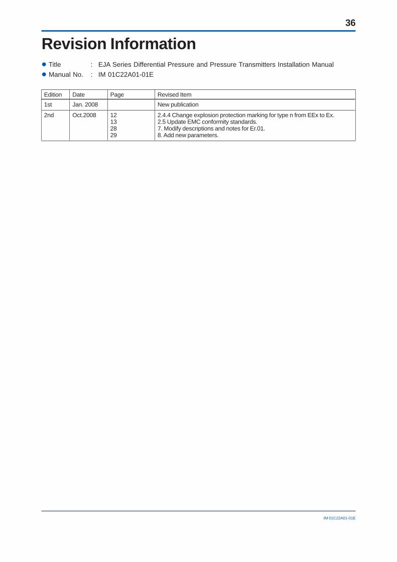
36
IM 01C22A01-01E
Revision Information Title : EJA Series Differential Pressure and Pressure Transmitters Installation Manual Manual No. : IM 01C22A01-01E
Edition Date Page Revised Item1st Jan. 2008 New publication
2nd Oct.2008 12132829
2.4.4 Change explosion protection marking for type n from EEx to Ex.2.5 Update EMC conformity standards.7. Modify descriptions and notes for Er.01.8. Add new parameters.
www.yokogawa.com/fld/
Copyright © 2008 Yokogawa Electric Corporation. All Rights Reserved.
EJA Series Electronic User’s Manual IM 01C22A11-01E
System Requirements OS Microsoft Windows 2000 (Professional) / XP (Professional) CPU Pentium 300 MHz or higher RAM 128 MB or more Display 800 × 600 SVGA or higher, 256 colors
Contents
Trademarks
This CD-R contains information in PDF format that is necessary for safe and effective operation of the product.
Microsoft, MS-DOS, Windows and Windows NT are either registered trademarks or trademarks of Microsoft Corporation in the United States and/or other countries.Other company and product names are trademarks or registered trademarks of their respective holders.
WARNING: This CD contains software, and is for use in a computer only. Do not play this on an audio CD player, as the high volume may damage your hearing or audio speakers.
for Windows
Not for sale
YOKOGAWA CORPORATION OF AMERICA2 Dart Road, Newnan, Georgia 30265-1094, U.S.A.Phone : 1-800-888-6400Fax : 1-770-254-0928
YOKOGAWA EUROPE B. V.Databankweg 20 Amersfoort 3821 AL, THE NETHERLANDSPhone : 31-33-464-1611 Fax : 31-33-464-1610
Branch Sales Offices / Wien (Austria), Zaventem (Belgium), Ratingen (Germany), Madrid (Spain), Runcorn (United Kingdom), Milano (Italy), Velizy-Villacoublay (France), Budapest (Hungary), Stockholm (Sweden), Sola(Norway), Warszawa (Poland), Vila Nova de Gaia (Portugal), Bucharest(Romania)
YOKOGAWA AMERICA DO SUL LTDA.Praca Acapulco, 31 - Santo Amaro. Sao Paulo/SP - BRAZILPhone : 55-11-5681-2400 Fax : 55-11-5681-4434
YOKOGAWA ENGINEERING ASIA PTE. LTD.5 Bedok South Road, 469270 SINGAPOREPhone : 65-6241-9933 Fax : 65-6241-2606
YOKOGAWA ELECTRIC KOREA CO., LTD.14-1, Yangpyongdong-4Ga, Youngdeungpo-Gu, Seoul, 150-866 KOREAPhone : 82-2-2628-6000 Fax : 82-2-2628-6400
YOKOGAWA AUSTRALIA PTY. LTD.Tower A, 112-118 Talavera Road, Macquarie Park,N.S.W.2113, AUSTRALIAPhone : 61-2-8870-1100 Fax : 61-2-8870-1111
YOKOGAWA INDIA LTD.Plot No.96 Electronic City Complex, Hosur Road, Bangalore 560100, INDIAPhone : 91-80-4158-6000 Fax : 91-80-2852-0625
YOKOGAWA CHINA CO., LTD.Tangyue Pavilion, Xi'an software park No.72,Keji 2nd Road Xi'an High-tech Industries Development Zone Xi'an 710075,CHINAPhone : 86-29-87669988 Fax : 86-29-87607800
YOKOGAWA ELECTRIC CORPORATIONHeadquarters2-9-32, Nakacho, Musashino-shi, Tokyo, 180-8750 JAPAN
Branch Sales OfficesNagoya, Osaka, Hiroshima, Fukuoka, Sapporo, Sendai, Ichihara, Toyota,Kanazawa, Okayama, and Kitakyusyu.
May ‘08
Printed in Japan


![User’s - Yokogawa Electric s Manual Yokogawa Electric Corporation IM 21B3C1-01E VP200 Current-to-Pneumatic Positioner [Style : S3] IM 21B3C1-01E 7th Edition IM 21B3C1-01E i INTRODUCTION](https://img.pdfslide.us/doc/110x75/5abb71277f8b9a441d8cd2f8/users-yokogawa-electric-s-manual-yokogawa-electric-corporation-im-21b3c1-01e.jpg)


![User’s Manual Model EJA510A and EJA530A Absolute ...€™s Manual Model EJA510A and EJA530A Absolute Pressure and Gauge Pressure Transmitters [Style: S2] IM 01C21F01-01E IM 01C21F01-01E](https://img.pdfslide.us/doc/110x75/5adcb59c7f8b9a9a768be483/users-manual-model-eja510a-and-eja530a-absolute-s-manual-model-eja510a.jpg)

![User's AXF Manual Magnetic Flowmeter Integral Flowmeter ... · Magnetic Flowmeter Integral Flowmeter/ Remote Flowtube [Hardware Edition] IM 01E20D01-01E IM 01E20D01-01E 7th Edition](https://img.pdfslide.us/doc/110x75/5e9c29fa54300501b21ae83a/users-axf-manual-magnetic-flowmeter-integral-flowmeter-magnetic-flowmeter-integral.jpg)


![Model DC402G Converter for Dual Cell Conductivity and ... · User’s Manual Model DC402G Converter for Dual Cell Conductivity and Resistivity [Style: S2] IM 12D08E02-01E IM 12D08E02-01E](https://img.pdfslide.us/doc/110x75/5ac2cf3c7f8b9a357e8e6c4f/model-dc402g-converter-for-dual-cell-conductivity-and-s-manual-model-dc402g.jpg)