Embed Size (px)
Citation preview

InstructionManual
Yokogawa Electric Corporation
IM 1C50T2-01E
YTA SeriesTemperature TransmitterFieldbus Communication
IM 1C50T2-01E1st Edition
i
CONTENTS
IM 1C50T2-01EFD No. IM 1C50T2-01E1st Edition: Oct. 2000(YK)All Rights Reserved, Copyright © 2000, Yokogawa Electric Corporation
CONTENTS
1. INTRODUCTION............................................................................................ 1-1
Regarding This Manual ............................................................................. 1-1 Warranty.................................................................................................... 1-1 Safety Precautions .................................................................................... 1-1
2. PART NAMES ............................................................................................... 2-1
3. ABOUT FIELDBUS ....................................................................................... 3-1
3.1 Outline ................................................................................................. 3-13.2 Internal Structure of YTA .................................................................... 3-1
3.2.1 System/network Management VFD ............................................. 3-13.2.2 Function Block VFD ..................................................................... 3-1
3.3 Logical Structure of Each Block .......................................................... 3-13.4 Wiring System Configuration .............................................................. 3-2
4. GETTING STARTED ..................................................................................... 4-1
4.1 Connection of Devices ........................................................................ 4-14.2 Host Setting ......................................................................................... 4-24.3 Bus Power ON .................................................................................... 4-24.4 Integration of DD ................................................................................. 4-24.5 Reading the Parameters ..................................................................... 4-34.6 Continuous Record of Values ............................................................. 4-34.7 Generation of Alarm ............................................................................ 4-3
5. CONFIGURATION ......................................................................................... 5-1
5.1 Network Design ................................................................................... 5-15.2 Network Definition ............................................................................... 5-15.3 Definition of Combining Function Blocks ............................................ 5-25.4 Setting of Tags and
Addresses ........................................................................................... 5-35.5 Communication Setting ....................................................................... 5-4
5.5.1 VCR Setting .................................................................................. 5-45.5.2 Function Block Execution Control ................................................ 5-5
5.6 Block Setting ....................................................................................... 5-55.6.1 Link Object ................................................................................... 5-55.6.2 Trend Object ................................................................................. 5-55.6.3 View Object .................................................................................. 5-65.6.4 Parameters of Transducer Block ............................................... 5-125.6.5 Parameters of AI Function Block ............................................... 5-145.6.6 Parameters of DI Function Block ............................................... 5-15
ii
CONTENTS
IM 1C50T2-01E
6. IN-PROCESS OPERATION .......................................................................... 6-1
6.1 Mode Transition .................................................................................. 6-16.2 Generation of Alarm ............................................................................ 6-1
6.2.1 Indication of Alarm ....................................................................... 6-16.2.2 Alarms and Events ....................................................................... 6-1
6.3 Simulation Function ............................................................................. 6-26.4 Operation of Integral Indicator ............................................................... 6-2
7. ERRORS AND WARNINGS.......................................................................... 7-1
7.1 Error and Warning Indications ............................................................ 7-17.2 Checking with LCD ............................................................................. 7-17.3 Checking with DEVICE_STATUS_1 to _8 of Resource Block ........... 7-47.4 Precautions on Warnings .................................................................... 7-8
8. HANDLING CAUTION................................................................................... 8-1
8.1 Installation of Explosionproof Type Transmitters ................................ 8-18.1.1 CSA Certification .......................................................................... 8-18.1.2 CENELEC (KEMA) Certification ................................................... 8-28.1.3 FM Certification ............................................................................ 8-2
9. GENERAL SPECIFICATIONS ...................................................................... 9-1
9.1 Standard Specifications ...................................................................... 9-19.2 Optional Specifications ........................................................................ 9-1
APPENDIX 1. LIST OF PARAMETERS FOR EACH BLOCK OF THE YTA .. A-1
A1.1 Resource Block .................................................................................... A-1A1.2 Al Function Block .................................................................................. A-3A1.3 Dl Function Block ................................................................................. A-5A1.4 Transducer Block .................................................................................. A-6A1.5 Unit and Code ................................................................................... A-10
Appendix 2. Parameters for Basic Settings, and How to Make andChange the Settings ................................................................................. A-11
A2.1 Basic Settings and Corresponding Parameters ................................ A-11A2.2 Making and Changing Basic Parameter Settings ............................. A-12A2.3 Setting Up the Transducer Block ...................................................... A-13A2.4 Setting Up AI Blocks ......................................................................... A-15A2.5 Setting Up DI Blocks ......................................................................... A-16
APPENDIX 3. FUNCTION BLOCK DIAGRAM ............................................... A-18
A3.1 AI Block Function Diagram ............................................................... A-18A3.2 DI Block Function Diagram ............................................................... A-18
APPENDIX 4. PID BLOCK .............................................................................. A-19
A4.1 Function Diagram ............................................................................... A-19A4.2 Functions of PID Block ....................................................................... A-19A4.3 Parameters of PID Block .................................................................... A-20
iii
CONTENTS
IM 1C50T2-01E
A4.4 PID Computation Details .................................................................... A-22A4.4.1 PV-proportional and -derivative Type PID (I-PD)
Control Algorithm........................................................................ A-22A4.4.2 PID Control Parameters ............................................................. A-22
A4.5 Control Output ................................................................................... A-22A4.5.1 Velocity Type Output Action ....................................................... A-22
A4.6 Direction of Control Action ................................................................ A-22A4.7 Control Action Bypass ....................................................................... A-22A4.8 Feed-forward ..................................................................................... A-22A4.9 Block Modes ...................................................................................... A-23
A4.9.1 Mode Transitions ....................................................................... A-23A4.10 Bumpless Transfer ........................................................................... A-23A4.11 Setpoint Limiters ............................................................................... A-24
A4.11.1 When PID Block Is in Auto Mode ............................................ A-24A4.11.2 When PID Block Is in Cas or RCas Mode ............................... A-24
A4.12 External-output Tracking .................................................................. A-24A4.13 Measured-value Tracking ................................................................. A-24A4.14 Initialization and Manual Fallback (IMan) ......................................... A-25A4.15 Manual Fallback ............................................................................... A-25A4.16 Auto Fallback .................................................................................... A-25A4.17 Mode Shedding upon Computer Failure .......................................... A-25
A4.17.1 SHED_OPT .............................................................................. A-25A4.18 Alarms............................................................................................... A-26
A4.18.1 Block Alarm (BLOCK_ALM) ..................................................... A-26A4.18.2 Process Alarms ........................................................................ A-26
A4.19 Example of Block Connections ........................................................ A-26A4.19.1 View Object for PID Function Block ......................................... A-27
APPENDIX 5. LINK MASTER FUNCTIONS ................................................... A-29
A5.1 Link Active Scheduler ........................................................................ A-29A5.2 Link Master ........................................................................................ A-29A5.3 Transfer of LAS ................................................................................. A-30A5.4 LM Functions ..................................................................................... A-31A5.5 LM Parameters .................................................................................. A-32
A5.5.1 LM Parameter List ...................................................................... A-32A5.5.2 Descriptions for LM Parameters ................................................ A-34
A5.6 FAQs ................................................................................................. A-36
REVISION RECORD

Blank Page
IM 1C50T2-01E1-1
1. INTRODUCTION
1. INTRODUCTION
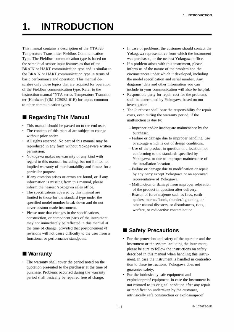
This manual contains a description of the YTA320Temperature Transmitter Fieldbus CommunicationType. The Fieldbus communication type is based onthe same dual sensor input features as that of theBRAIN or HART communication type and is similar tothe BRAIN or HART communication type in terms ofbasic performance and operation. This manual de-scribes only those topics that are required for operationof the Fieldbus communication type. Refer to theinstruction manual "YTA series Temperature Transmit-ter [Hardware]"(IM 1C50B1-01E) for topics commonto other communication types.
Regarding This Manual• This manual should be passed on to the end user.• The contents of this manual are subject to change
without prior notice.• All rights reserved. No part of this manual may be
reproduced in any form without Yokogawa’s writtenpermission.
• Yokogawa makes no warranty of any kind withregard to this manual, including, but not limited to,implied warranty of merchantability and fitness for aparticular purpose.
• If any question arises or errors are found, or if anyinformation is missing from this manual, pleaseinform the nearest Yokogawa sales office.
• The specifications covered by this manual arelimited to those for the standard type under thespecified model number break-down and do notcover custom-made instrument.
• Please note that changes in the specifications,construction, or component parts of the instrumentmay not immediately be reflected in this manual atthe time of change, provided that postponement ofrevisions will not cause difficulty to the user from afunctional or performance standpoint.
Warranty• The warranty shall cover the period noted on the
quotation presented to the purchaser at the time ofpurchase. Problems occurred during the warrantyperiod shall basically be repaired free of charge.
• In case of problems, the customer should contact theYokogawa representative from which the instrumentwas purchased, or the nearest Yokogawa office.
• If a problem arises with this instrument, pleaseinform us of the nature of the problem and thecircumstances under which it developed, includingthe model specification and serial number. Anydiagrams, data and other information you caninclude in your communication will also be helpful.
• Responsible party for repair cost for the problemsshall be determined by Yokogawa based on ourinvestigation.
• The Purchaser shall bear the responsibility for repaircosts, even during the warranty period, if themalfunction is due to:
- Improper and/or inadequate maintenance by thepurchaser.
- Failure or damage due to improper handling, useor storage which is out of design conditions.
- Use of the product in question in a location notconforming to the standards specified byYokogawa, or due to improper maintenance ofthe installation location.
- Failure or damage due to modification or repairby any party except Yokogawa or an approvedrepresentative of Yokogawa.
- Malfunction or damage from improper relocationof the product in question after delivery.
- Reason of force majeure such as fires, earth-quakes, storms/floods, thunder/lightening, orother natural disasters, or disturbances, riots,warfare, or radioactive contamination.
Safety Precautions• For the protection and safety of the operator and the
instrument or the system including the instrument,please be sure to follow the instructions on safetydescribed in this manual when handling this instru-ment. In case the instrument is handled in contradic-tion to these instructions, Yokogawa does notguarantee safety.
• For the intrinsically safe equipment andexplosionproof equipment, in case the instrument isnot restored to its original condition after any repairor modification undertaken by the customer,intrinsically safe construction or explosionproof

IM 1C50T2-01E1-2
1. INTRODUCTION
construction is damaged and may cause dangerouscondition. Please contact Yokogawa for any repairor modification required to the instrument.
• The following safety symbol marks are used in thisManual:
WARNING
Indicates a potentially hazardous situation which,if not avoided, could result in death or seriousinjury.
CAUTION
Indicates a potentially hazardous situation which,if not avoided, may result in minor or moderateinjury. It may also be used to alert againstunsafe practices.
IMPORTANT
Indicates that operating the hardware or softwarein this manner may damage it or lead to systemfailure.
NOTE
Draws attention to information essential forunderstanding the operation and features.
CAUTION
This instrument is tested and certified as intrinsi-cally safe type or explosionproof type. Pleasenote that the construction of the instrument,installation, external wiring, maintenance orrepair is strictly restricted, and non-observanceor negligence of these restriction would resultdangerous condition.
IM 1C50T2-01E2-1
2. PART NAMES
2. PART NAMES
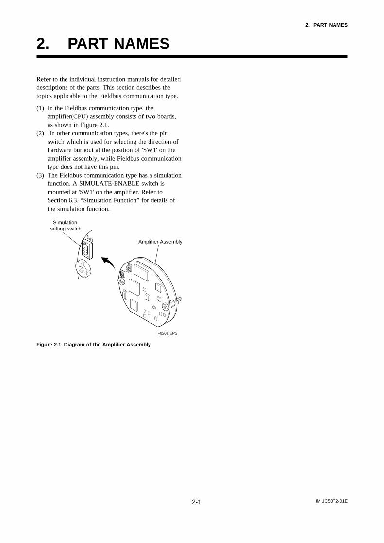
Refer to the individual instruction manuals for detaileddescriptions of the parts. This section describes thetopics applicable to the Fieldbus communication type.
(1) In the Fieldbus communication type, theamplifier(CPU) assembly consists of two boards,as shown in Figure 2.1.
(2) In other communication types, there's the pinswitch which is used for selecting the direction ofhardware burnout at the position of 'SW1' on theamplifier assembly, while Fieldbus communicationtype does not have this pin.
(3) The Fieldbus communication type has a simulationfunction. A SIMULATE-ENABLE switch ismounted at 'SW1' on the amplifier. Refer toSection 6.3, “Simulation Function” for details ofthe simulation function.
Simulation setting switch
Amplifier Assembly
F0201.EPS
Figure 2.1 Diagram of the Amplifier Assembly
IM 1C50T2-01E3-1
3. ABOUT FIELDBUS
3. ABOUT FIELDBUS
3.1 OutlineFieldbus is a bi-directional digital communicationprotocol for field devices, which offers an advancement inimplementation technologies for process control systemsand is widely employed by numerous field devices.
YTA Series Fieldbus communication type employs thespecification standardized by The Fieldbus Foundation,and provides interoperability between Yokogawadevices and those produced by other manufacturers.Fieldbus comes with software consisting of four AIfunction blocks and four DI function blocks, providingthe means to implement a flexible instrumentationsystem.
For information on other features, engineering, design,construction work, startup and maintenance ofFieldbus, refer to “Fieldbus Technical Information” (TI38K3A01-01E).
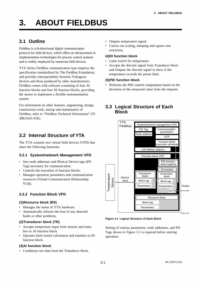
3.2 Internal Structure of YTAThe YTA contains two virtual field devices (VFD) thatshare the following functions.
3.2.1 System/network Management VFD
• Sets node addresses and Phisical Device tags (PDTag) necessary for communication.
• Controls the execution of function blocks.• Manages operation parameters and communication
resources (Virtual Communication Relationship:VCR).
3.2.2 Function Block VFD
(1)Resource block (RS)• Manages the status of YTA hardware.• Automatically informs the host of any detected
faults or other problems.
(2)Transducer block (TR)• Accepts temperature input from sensors and trans-
fers to AI function block.• Operates limit swtich calculation and transfers to DI
function block.
(3)AI function block• Conditions raw data from the Transducer block.
• Outputs temperature signal.• Carries out scaling, damping and square root
extraction.
(4)DI function block• Limit switch for temperature.• Accepts the discrete signal from Transducer block
and Outputs the discrete signal to show if thetemperature exceeds the preset limit.
(5)PID function block• Performs the PID control computation based on the
deviation of the measured value from the setpoint.
3.3 Logical Structure of EachBlock
F0301.EPS
YTA Fieldbus System/network management VFD
Function block VFD
Link Master (option)
PD Tag
Sensor input
Resource block
Block tag
Parameters
PID function block (option)
Communication parameters
VCRNode address
Function block execution schedule
DI function block
Output
AI function block
Block tag
OUT
Parameters
Transducer block
Block tag
Parameters
Tem
pera
ture
Sen
sor
Figure 3.1 Logical Structure of Each Block
Setting of various parameters, node addresses, and PDTags shown in Figure 3.1 is required before startingoperation.

IM 1C50T2-01E3-2
3. ABOUT FIELDBUS
3.4 Wiring System ConfigurationThe number of devices that can be connected to asingle bus and the cable length vary depending onsystem design. When constructing systems, both thebasic and overall design must be carefully consideredto allow device performance to be fully exhibited.
IM 1C50T2-01E4-1
4. GETTING STARTED
4. GETTING STARTED
Fieldbus is fully dependent upon digital communica-tion protocol and differs in operation from conven-tional 4 to 20 mA transmission and the BRAIN orHART communication protocol. It is recommendedthat novice users use field devices in accordance withthe procedures described in this section. The proce-dures assume that field devices will be set up on abench or an instrument shop.
4.1 Connection of DevicesThe following instruments are required for use withFieldbus devices:
• Power supply:Fieldbus requires a dedicated power supply. It isrecommended that current capacity be well over thetotal value of the maximum current consumed by alldevices (including the host). Conventional DCcurrent cannot be used as is.
• Terminator:Fieldbus requires two terminators. Refer to thesupplier for details of terminators that are attachedto the host.
• Field devices:Connect Fieldbus communication type YTA320.Two or more YTA320 devices or other devices canbe connected.
• Host:Used for accessing field devices. A dedicated host(such as DCS) is used for an instrumentation linewhile dedicated communication tools are used forexperimental purposes. For operation of the host,refer to the instruction manual for each host. Nodetails of the host are explained in the rest of thismaterial.
• Cable:Used for connecting devices. Refer to “FieldbusTechnical Information” (TI 38K3A01-01E) fordetails of instrumentation cabling. If the total lengthof the cable is in a range of 2 to 3 meters forlaboratory or other experimental use, the followingsimplified cable (a twisted pair wire with a crosssection of 0.9 mm2 or more and cycle period ofwithin 5 cm (2 inches) may be used. Termination
processing depends on the type of device beingdeployed. For YTA, use an M4 screw terminal claw.Some hosts require a connector.
Refer to Yokogawa when making arrangements topurchase the recommended equipment.
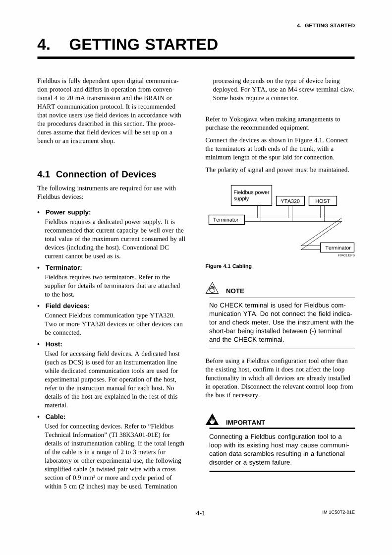
Connect the devices as shown in Figure 4.1. Connectthe terminators at both ends of the trunk, with aminimum length of the spur laid for connection.
The polarity of signal and power must be maintained.
YTA320
Fieldbus power supply
Terminator
Terminator
HOST
F0401.EPS
Figure 4.1 Cabling
NOTE
No CHECK terminal is used for Fieldbus com-munication YTA. Do not connect the field indica-tor and check meter. Use the instrument with theshort-bar being installed between (-) terminaland the CHECK terminal.
Before using a Fieldbus configuration tool other thanthe existing host, confirm it does not affect the loopfunctionality in which all devices are already installedin operation. Disconnect the relevant control loop fromthe bus if necessary.
IMPORTANT
Connecting a Fieldbus configuration tool to aloop with its existing host may cause communi-cation data scrambles resulting in a functionaldisorder or a system failure.

IM 1C50T2-01E4-2
4. GETTING STARTED
4.2 Host SettingTo activate Fieldbus, the following settings arerequired for the host.
IMPORTANT
Do not turn off the power immediately aftersetting. When the parameters are saved toEEPROM, the redundant processing is executedfor the improvement of reliability. If the power isturned off within 60 seconds after setting ismade, the modified parameters are not savedand the settings may return to the originalvalues.
Table 4.1 Operation Parameters
T0401.EPS
Symbol Parameter Description and Settings
V (ST) Slot-Time Set 4 or greater value.
V (MID) Minimum-Inter-PDU-Delay
Set 4 or greater value.
V (MRD) Maximum-Reply-Delay
Set so that V (MRD) V (ST) is 12 or greater
V (FUN) First-Unpolled-Node Indicate the address next to the address range used by the host. Set 0x15 or greater.
V (NUN) Number-of-consecutive-Unpolled-Node
Unused address range. YTA address is factory-set to 0xF3. Set this address to be within the range of the BASIC device in Figure 4.2.
Not used0x00
0x10
0xF70xF8
0xFB0xFC
0xFF
V(FUN)
V(FUN)V(NUN)YTA(0xF3)
LM device
Unused V(NUN)
Note 1: LM device: with bus control function (Link Master function)Note 2: BASIC device: without bus control function
BASIC device
Default address
Portable device address
F0402.EPS
Figure 4.2 Available Address Range
4.3 Bus Power ONTurn on the power of the host and the bus. Where theYTA is equipped with an LCD indicator, first allsegments are lit, then the display begins to operate. Ifthe indicator is not lit, check the polarity of the powersupply.
Using the host device display function, check that theYTA is in operation on the bus. Unless otherwisespecified, the following settings are in effect whenshipped from the factory.
PD tag: TT1001Node address: 243 (hexadecimal 0xF3)Device ID: 5945430005xxxxxxxx (xxxxxxxx = a total
of 8 alphanumeric characters)
If no YTA is detected, check the available addressrange and the polarity of the power supply. If the nodeaddress and PD tag are not specified when ordering,default value is factory set. If two or more YTAs areconnected at a time with default value, one YTA willkeep the address upon shipment while the other willhave a default address as they have the same initialaddres. Separately connect each YTA and set adifferent address for each.
4.4 Integration of DDIf the host supports DD (Device Description), the DDof the YTA needs to be installed. Check if host has thefollowing directory under its default DD directory.
594543\0005(594543 is the manufacturer number of YokogawaElectric Corporation, and 0005 is the YTA devicenumber, respectively.)
If this directory is not found, DD of YTA has not beenincluded. Create the above directory and copy the DDfile (0m0n.ffo,0m0n.sym) (m, n is a numeral) (to besupplied separately) into the directory.
Once the DD is installed in the directory, the name andattribute of all parameters of the YTA are displayed.
Off-line configuration is possible by using Capabilityfile (CFF).
IM 1C50T2-01E4-3
4. GETTING STARTED
NOTE
Ensure to use the suitable file for the device.YTA has three types, one with the standardfunction blocks, one with /LC1(additional PIDand LAS function) and one with /LC2(additional2 PIDs and LAS function). If the different typeCFF is used, some errors may occur at down-loading to the device.
4.5 Reading the ParametersTo read YTA parameters, select the AI1 block of theYTA from the host screen and read the OUT param-eter. The current temperature which is assign to AI1block is displayed. Sensor 1 input is assigned to AI1block upon shipment. Check that actual ofMODE_BLOCK of the function block and resourceblock is set to Auto, and increase the temperaturemeasured by Sensor1 and read the parameter again. Anew designated value should be displayed.
4.6 Continuous Record of ValuesIf the host has a function of continuously recording theindications, use this function to list the indications(values). Depending on the host being used, it may benecessary to set the schedule of Publish (the functionthat transmits the indication on a periodic basis).
4.7 Generation of AlarmIf the host is allowed to receive alarms, generation ofan alarm can be attempted from YTA. In this case, setthe reception of alarms on the host side. YTA’s VCR-6is factory-set for this purpose. For practical purposes,all alarms are placed in a disabled status; for thisreason, it is recommended that you first use one ofthese alarms on a trial basis. Set the value of linkobject-3 (index 30002) as “0, 298, 0, 6, 0”. Refer tosection 5.6.1 Link Object for details.
Since the LO_PRI parameter (index 4029) of the AI1block is set to “0”, try setting this value to “3”. Selectthe Write function from the host in operation, specifyan index or variable name, and write “3” to it.
The LO_LIM parameter (index 4030) of the AI1 blockdetermines the limit at which the lower bound alarmfor the process value is given. In usual cases, a verysmall value is set to this limit. Set the value which isapparantely higher than expected measured value to thelimit. For example, in case masuering room tempera-ture of 28C, SET '50(C)' to the limit. Since themeasured temperature is lower than the limit, lowerbound alarm is raised. Check that the alarm can bereceived at the host. When the alarm is confirmed,transmission of the alarm is suspended.
The above-mentioned items are a description of thesimple procedure to be carried out until YTA isconnected to Fieldbus. In order to take full advantageof the performance and functionality of the device, it isrecommended that it be read together with Chapter 5,which describes how to use the YTA.
IM 1C50T2-01E5-1
5. CONFIGURATION
5. CONFIGURATION
This chapter contains information on how to adapt thefunction and performance of the YTA to suit specificapplications. Because two or more devices are con-nected to Fieldbus, settings including the requirementsof all devices need to be determined. Practically, thefollowing steps must be taken.
(1)Network designDetermines the devices to be connected to Fieldbusand checks the capacity of the power supply.
(2)Network definitionDetermines the tag and node addresses for alldevices.
(3)Definition of combining function blocksDetermines the method for combination betweeneach function block.
(4)Setting tags and addressesSets the PD Tag and node addresses one by one foreach device.
(5)Communication settingSets the link between communication parametersand function blocks.
(6)Block settingSets the parameters for function blocks.
The following section describes each step of theprocedure in the order given. Using a dedicatedconfiguration tool allows the procedure to be signifi-cantly simplified. This section describes the procedureto be assigned for a host which has relatively simplefunctions. Refer to Appendix 5 when the YTA is usedas Link Master.
5.1 Network DesignSelect the devices to be connected to the Fieldbusnetwork. The following instruments are necessary foroperation of Fieldbus.
• Power supplyFieldbus requires a dedicated power supply. It isrecommended that current capacity be well over thetotal value of the maximum current consumed by alldevices (including the host). Conventional DCcurrent cannot be used as is.
• TerminatorFieldbus requires two terminators. Refer to thesupplier for details of terminators that are attachedto the host.
• Field devicesConnect the field devices necessary for instrumenta-tion. YTA has passed the interoperability testconducted by The Fieldbus Foundation. In order toproperly start Fieldbus, it is recommended that thedevices used satisfy the requirements of the abovetest.
• HostUsed for accessing field devices. A minimum of onedevice with bus control function is needed.
• CableUsed for connecting devices. Refer to “FieldbusTechnical Information” for details of instrumenta-tion cabling. Provide a cable sufficiently long toconnect all devices. For field branch cabling, useterminal boards or a connection box as required.
First, check the capacity of the power supply. Thepower supply capacity must be greater than the sum ofthe maximum current consumed by all devices to beconnected to Fieldbus. The maximum current con-sumed (power supply voltage 9 V to 32 V) for YTA is16.6 mA. The cable must have the spur in a minimumlength with terminators installed at both ends of thetrunk.
5.2 Network DefinitionBefore connection of devices with Fieldbus, define theFieldbus network. Allocate PD Tag and node addressesto all devices (excluding such passive devices asterminators).
The PD Tag is the same as the conventional one usedfor the device. Up to 32 alphanumeric characters maybe used for definition. Use a hyphen as a delimiter asrequired.
The node address is used to specify devices forcommunication purposes. Because data is too long fora PD Tag, the host uses the node address in place ofthe PD Tag for communication. A range of 16 to 247

IM 1C50T2-01E5-2
5. CONFIGURATION
(or hexadecimal 10 to F7) can be set. The device (LMdevice) with bus control function (Link Masterfunction) is allocated from a smaller address number(16) side, and other devices (BASIC device) withoutbus control function allocated from a larger addressnumber (247) side respectively. Place YTA in therange of the BASIC device. When the YTA is used asLink Master, place YTA in the range of LM device.Set the range of addresses to be used to the LM device.Set the following parameters.
Table 5.1 Parameters for Setting Address Range
T0501.EPS
V (FUN) First-Unpolled-Node Indicates the address next to the address range used for the host or other LM device.
V (NUN) Number-of-consecutive-Unpolled-Node
Unused address range
Symbol Parameters Description
The devices within the address range written as“Unused” in Figure 5.1 cannot be used on a Fieldbus.For other address ranges, the range is periodicallychecked to identify when a new device is mounted.Care must be taken not to allow the address range tobecome wider, which can lead to exhaustive consump-tion of Fieldbus communication performance.
Not used0x00
0x10
0xF70xF8
0xFB0xFC
0xFF
V(FUN)
V(FUN)V(NUN)
LM device
Unused V(NUN)
BASIC device
Default address
Portable device address
F0501.EPS
Figure 5.1 Available Range of Node Addresses
To ensure stable operation of Fieldbus, determine theoperation parameters and set them to the LM devices.While the parameters in Table 5.2 are to be set, theworst-case value of all the devices to be connected tothe same Fieldbus must be used. Refer to the specifica-tion of each device for details. Table 5.2 lists YTAspecification values.
Table 5.2 Operation Parameter Values of the YTA to beSet to LM Devices
Indicates the time necessary for immediate reply of thje device. Unit of time is in octets (256 µs). Set maximum specification for all devices. For YTA, set a value of 4 or greater.
T0502.EPS
Symbol Parameters Description and Settings
V (ST) Slot-Time
V (MID) Minimum-Inter-PDU-Delay
Minimum value of communication data intervals. Unit of time is in octets (256 µs). Set the maximum specification for all devices. For YTA, set a value of 4 or greater.
V (MRD) Maximum-Reply-Delay The worst case time elapsed until a reply is recorded. The unit is Slot-time; set the value so that V (MRD) V (ST) is the maximum value of the specification for all devices. For YTA, the setting must be a value of 12 or greater.
5.3 Definition of CombiningFunction Blocks
The input/output parameters for function blocks arecombined. For the YTA, four AI blocks outputparameter (OUT), four DI blocks output parameter(OUT_D) and PID block are subject to combination.They are combined with the input of the control blockas necessary. Practically, setting is written to the YTAlink object with reference to “Block setting” in Section5.6 for details. It is also possible to read values fromthe host at proper intervals instead of connecting theYTA block output to other blocks.
The combined blocks need to be executed synchro-nously with other blocks on the communicationsschedule. In this case, change the YTA scheduleaccording to the following table. Enclosed values in thetable are factory-settings.
Table 5.3 Execution Schedule of the YTA Function Blocks
T0503.EPS
Index ParametersSetting (Enclosed is
factory-setting)
269(SM)
MACROCYCLE_DURATION
Cycle (MACROCYCLE) period of control or measurement. Unit is 1/32 ms. (16000 = 0.5 s)
276(SM)
FB_START_ENTRY.1 AI1 block startup time. Elapsed time from the start of MACROCYCLE specified in 1/32 ms. (0 = 0 s)
277(SM)
FB_START_ENTRY.2
278 to
FB_START_ENTRY.3 to FB_START_ENTRY.10 285
(SM)
AI2 block startup time. Elapsed time from the start of MACROCYCLE specified in 1/32 ms. (4000 = 125ms)
Not used.
IM 1C50T2-01E5-3
5. CONFIGURATION
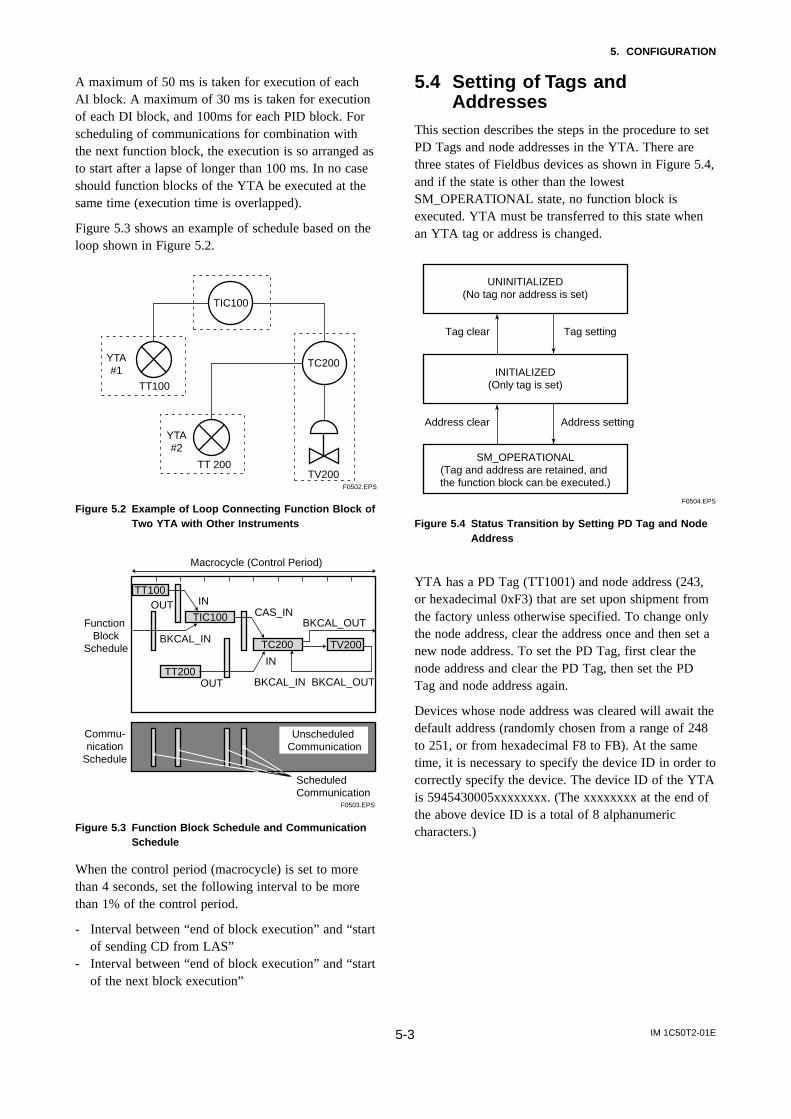
A maximum of 50 ms is taken for execution of eachAI block. A maximum of 30 ms is taken for executionof each DI block, and 100ms for each PID block. Forscheduling of communications for combination withthe next function block, the execution is so arranged asto start after a lapse of longer than 100 ms. In no caseshould function blocks of the YTA be executed at thesame time (execution time is overlapped).
Figure 5.3 shows an example of schedule based on theloop shown in Figure 5.2.
F0502.EPS
TIC100
TC200
TV200TT 200
YTA#2
TT100
YTA#1
Figure 5.2 Example of Loop Connecting Function Block ofTwo YTA with Other Instruments
TT100
TIC100
TC200 TV200
TT200
Function Block
Schedule
Commu-nication
Schedule
OUT IN
OUT
CAS_INBKCAL_OUT
BKCAL_IN
BKCAL_IN
BKCAL_OUT
IN
Unscheduled Communication
Scheduled Communication
F0503.EPS
Macrocycle (Control Period)
Figure 5.3 Function Block Schedule and CommunicationSchedule
When the control period (macrocycle) is set to morethan 4 seconds, set the following interval to be morethan 1% of the control period.
- Interval between “end of block execution” and “startof sending CD from LAS”
- Interval between “end of block execution” and “startof the next block execution”
5.4 Setting of Tags andAddresses
This section describes the steps in the procedure to setPD Tags and node addresses in the YTA. There arethree states of Fieldbus devices as shown in Figure 5.4,and if the state is other than the lowestSM_OPERATIONAL state, no function block isexecuted. YTA must be transferred to this state whenan YTA tag or address is changed.
UNINITIALIZED(No tag nor address is set)
Tag clear Tag setting
INITIALIZED(Only tag is set)
SM_OPERATIONAL(Tag and address are retained, and the function block can be executed.)
Address clear
F0504.EPS
Address setting
Figure 5.4 Status Transition by Setting PD Tag and NodeAddress
YTA has a PD Tag (TT1001) and node address (243,or hexadecimal 0xF3) that are set upon shipment fromthe factory unless otherwise specified. To change onlythe node address, clear the address once and then set anew node address. To set the PD Tag, first clear thenode address and clear the PD Tag, then set the PDTag and node address again.
Devices whose node address was cleared will await thedefault address (randomly chosen from a range of 248to 251, or from hexadecimal F8 to FB). At the sametime, it is necessary to specify the device ID in order tocorrectly specify the device. The device ID of the YTAis 5945430005xxxxxxxx. (The xxxxxxxx at the end ofthe above device ID is a total of 8 alphanumericcharacters.)
IM 1C50T2-01E5-4
5. CONFIGURATION
5.5 Communication SettingTo set the communication function, it is necessary tochange the database residing in SM-VFD.
5.5.1 VCR Setting
Set VCR (Virtual Communication Relationship), whichspecifies the called party for communication andresources. YTA has 30 VCRs whose application can bechanged, except for the first VCR, which is used formanagement.
YTA has VCRs of four types:
Server(QUB) VCRA Server responds to requests from a host. Thiscommunication needs data exchange. This type ofcommunication is called QUB (Queued User-triggered Bidirectional) VCR.
Source (QUU) VCRA Source multicasts alarms or trends to otherdevices. This type of communication is called QUU(Queued User-triggered Unidirectional) VCR.
Publisher (BNU) VCRA Publisher multicasts AI block and DI block outputto another function block(s). This type of communi-cation is called BNU (Buffered Network-triggeredUnidirectional) VCR.
Subscriber (BNU) VCRA Subscriber receives output of another functionblock(s) by PID block.
A Server VCR is capable to respond to requests from aClient (QUB) VCR after the Client initiates connectionto the Server successfully. A Source VCR transmitsdata without established connection. A Sink (QUU)VCR on another device can receive it if the Sink isconfigured so. A Publisher VCR transmits data whenLAS requests so. An explicit connection is establishedfrom Subscriber (BNU) VCR(s) so that a Subscriberknows the format of published data.
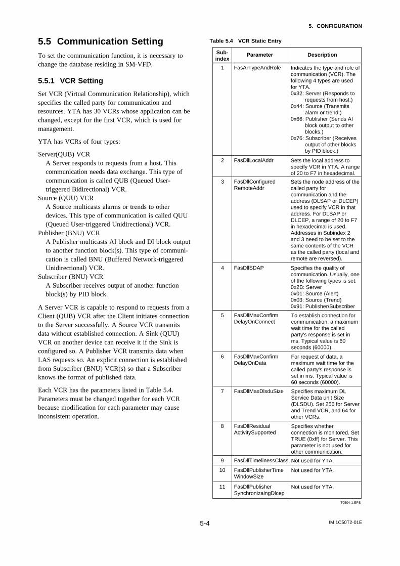
Each VCR has the parameters listed in Table 5.4.Parameters must be changed together for each VCRbecause modification for each parameter may causeinconsistent operation.
Table 5.4 VCR Static Entry
T0504-1.EPS
Sub-index
Parameter Description
1 FasArTypeAndRole Indicates the type and role of communication (VCR). The following 4 types are used for YTA.0x32: Server (Responds to
requests from host.)0x44: Source (Transmits
alarm or trend.)0x66: Publisher (Sends AI
block output to other blocks.)
0x76: Subscriber (Receives output of other blocks by PID block.)
2 FasDllLocalAddr Sets the local address to specify VCR in YTA. A range of 20 to F7 in hexadecimal.
3 FasDllConfiguredRemoteAddr
Sets the node address of the called party for communication and the address (DLSAP or DLCEP) used to specify VCR in that address. For DLSAP or DLCEP, a range of 20 to F7 in hexadecimal is used. Addresses in Subindex 2 and 3 need to be set to the same contents of the VCR as the called party (local and remote are reversed).
4 FasDllSDAP Specifies the quality of communication. Usually, one of the following types is set.0x2B: Server0x01: Source (Alert)0x03: Source (Trend)0x91: Publisher/Subscriber
5 FasDllMaxConfirmDelayOnConnect
To establish connection for communication, a maximum wait time for the called party's response is set in ms. Typical value is 60 seconds (60000).
6 FasDllMaxConfirmDelayOnData
For request of data, a maximum wait time for the called party's response is set in ms. Typical value is 60 seconds (60000).
7 FasDllMaxDlsduSize Specifies maximum DL Service Data unit Size (DLSDU). Set 256 for Server and Trend VCR, and 64 for other VCRs.
8 FasDllResidualActivitySupported
Specifies whether connection is monitored. Set TRUE (0xff) for Server. This parameter is not used for other communication.
9 FasDllTimelinessClass Not used for YTA.
10 FasDllPublisherTimeWindowSize
Not used for YTA.
11 FasDllPublisherSynchronizaingDlcep
Not used for YTA.
IM 1C50T2-01E5-5
5. CONFIGURATION
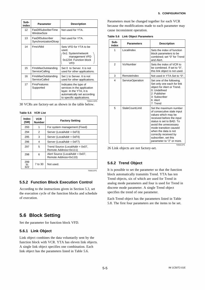
T0504-2.EPS
13 FasDllSubscriberSynchronizationDlcep
Not used for YTA.
14 FmsVfdId Sets VFD for YTA to be used. 0x1: System/network
management VFD0x1234: Function block
VFD
15 FmsMaxOutstandingServiceCalling
Set 0 to Server. It is not used for other applications.
16 FmsMaxOutstandingServiceCalled
Set 1 to Server. It is not used for other applications.
17 FmsFeaturesSupported
Indicates the type of services in the application layer. In the YTA, it is automatically set according to specific applications.
Sub-index Parameter Description
12 FasDllSubsriberTimeWindowSize
Not used for YTA.
30 VCRs are factory-set as shown in the table below.
Table 5.5 VCR List
T0505.EPS
Index(SM)
VCR Number
Factory Setting
293 For system management (Fixed)1
294 Server (LocalAddr = 0xF3)2
295 Server (LocalAddr = 0xF4)3
296 Server (LocalAddr = 0xF7)4
297 Trend Source (LocalAddr = 0x07, Remote Address=0x111)
5
298 6
299
Alert Source (LocalAddr = 0x07, Remote Address=0x110)
7 to 30322to Not used.
5.5.2 Function Block Execution Control
According to the instructions given in Section 5.3, setthe execution cycle of the function blocks and scheduleof execution.
5.6 Block SettingSet the parameter for function block VFD.
5.6.1 Link Object
Link object combines the data voluntarily sent by thefunction block with VCR. YTA has eleven link objects.A single link object specifies one combination. Eachlink object has the parameters listed in Table 5.6.
Parameters must be changed together for each VCRbecause the modifications made to each parameter maycause inconsistent operation.
Table 5.6 Link Object Parameters
T0506.EPS
Sub-index
Parameters Description
1 LocalIndex Sets the index of function block parameters to be combined; set “0” for Trend and Alert.
2 VcrNumber Sets the index of VCR to be combined. If set to “0”, this link object is not used.
3 RemoteIndex Not used in YTA.Set to “0”.
5 StaleCountLimit Set the maximum number of consecutive stale input values which may be received before the input status is set to BAD. To avoid the unnecessary mode transition caused when the data is not correctly received by subscriber, set this parameter to “2” or more.
4 ServiceOperation Set one of the following. Set only one each for link object for Alert or Trend.0: Undefined2: Publisher3: Subscriber6: Alert7: Trend
26 Link objects are not factory-set.
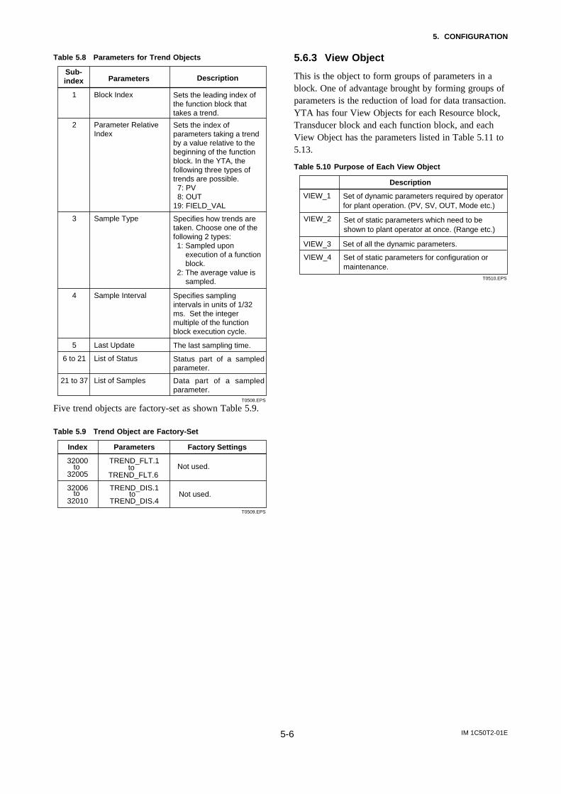
5.6.2 Trend Object
It is possible to set the parameter so that the functionblock automatically transmits Trend. YTA has tenTrend objects, six of which are used for Trend inanalog mode parameters and four is used for Trend indiscrete mode parameter. A single Trend objectspecifies the trend of one parameter.
Each Trend object has the parameters listed in Table5.8. The first four parameters are the items to be set.
IM 1C50T2-01E5-6
5. CONFIGURATION
Table 5.8 Parameters for Trend Objects
T0508.EPS
Sub-index Parameters Description
1 Block Index Sets the leading index of the function block that takes a trend.
2 Parameter Relative Index
Sets the index of parameters taking a trend by a value relative to the beginning of the function block. In the YTA, the following three types of trends are possible. 7: PV 8: OUT19: FIELD_VAL
3 Sample Type Specifies how trends are taken. Choose one of the following 2 types:1: Sampled upon
execution of a function block.
2: The average value is sampled.
4 Sample Interval Specifies sampling intervals in units of 1/32 ms. Set the integer multiple of the function block execution cycle.
5 Last Update The last sampling time.
6 to 21 List of Status Status part of a sampled parameter.
21 to 37 List of Samples Data part of a sampled parameter.
Five trend objects are factory-set as shown Table 5.9.
Table 5.9 Trend Object are Factory-Set
T0509.EPS
Index Parameters Factory Settings
32000Not used.
TREND_FLT.1
32005to
Not used.32010
TREND_FLT.6
32006 TREND_DIS.1
to
TREND_DIS.4to to
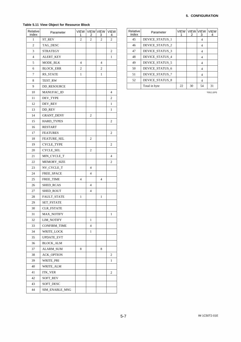
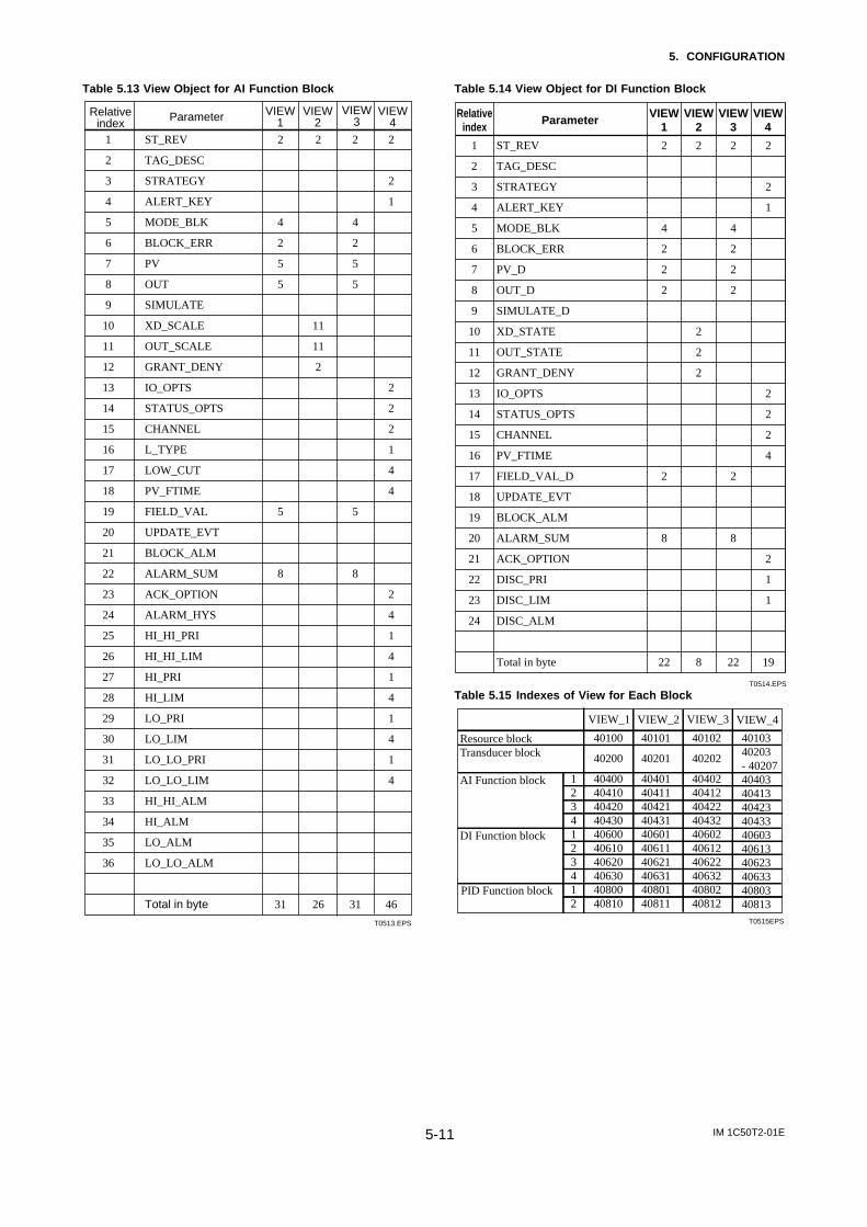
5.6.3 View Object
This is the object to form groups of parameters in ablock. One of advantage brought by forming groups ofparameters is the reduction of load for data transaction.YTA has four View Objects for each Resource block,Transducer block and each function block, and eachView Object has the parameters listed in Table 5.11 to5.13.
Table 5.10 Purpose of Each View Object
VIEW_1
VIEW_2
VIEW_3
VIEW_4
Set of all the dynamic parameters.
Description
Set of dynamic parameters required by operator for plant operation. (PV, SV, OUT, Mode etc.)
Set of static parameters which need to be shown to plant operator at once. (Range etc.)
Set of static parameters for configuration or maintenance.
T0510.EPS
IM 1C50T2-01E5-7
5. CONFIGURATION
Table 5.11 View Object for Resource Block
1 ST_REV 2
2 TAG_DESC
3 STRATEGY
4 ALERT_KEY
5 MODE_BLK 4
6 BLOCK_ERR 2
7 RS_STATE
2 2
4
2
1 1
2
2
1
Relativeindex
Parameter VIEW1
VIEW2
VIEW3
VIEW4
T0511.EPS
45 DEVICE_STATUS_1
46 DEVICE_STATUS_2
47 DEVICE_STATUS_3
4
4
4
4
4
4
22 30 54 31
48 DEVICE_STATUS_4
49 DEVICE_STATUS_5 4
450 DEVICE_STATUS_6
51 DEVICE_STATUS_7
52 DEVICE_STATUS_8
Relativeindex
Parameter VIEW1
VIEW2
VIEW3
VIEW4
Total in byte
8 TEST_RW
9 DD_RESOURCE
10 MANUFAC_ID
11 DEV_TYPE
12 DEV_REV
13 DD_REV
14 GRANT_DENY
15 HARD_TYPES
16 RESTART
17 FEATURES
18 FEATURE_SEL
19 CYCLE_TYPE
20 CYCLE_SEL
21 MIN_CYCLE_T
22 MEMORY_SIZE
23 NV_CYCLE_T
24 FREE_SPACE
425 FREE_TIME
26 SHED_RCAS
27 SHED_ROUT
128 FAULT_STATE
29 SET_FSTATE
30 CLR_FSTATE
41 ITK_VER
42 SOFT_REV
43 SOFT_DESC
44 SIM_ENABLE_MSG
8
2
2
2
4
4
4
4
1
4
1
4
1
8
4
2
1
1
2
2
2
4
2
1
2
1
2
31 MAX_NOTIFY
32 LIM_NOTIFY
33 CONFIRM_TIME
34 WRITE_LOCK
35 UPDATE_EVT
36 BLOCK_ALM
37 ALARM_SUM
38 ACK_OPTION
39 WRITE_PRI
40 WRITE_ALM
IM 1C50T2-01E5-8
5. CONFIGURATION
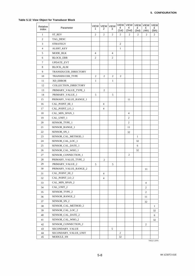
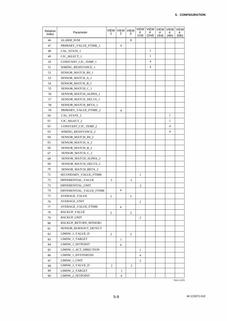
Table 5.12 View Object for Transducer Block
T0512-1.EPS
Relativeindex Parameter
VIEW1
VIEW2
VIEW3
VIEW4
(1st)
1 ST_REV 2
2 TAG_DESC
3 STRATEGY
4 ALERT_KEY
5 MODE_BLK 4
6 BLOCK_ERR 2
7 UPDATE_EVT
8 BLOCK_ALM
9 TRANSDUCER_DIRECTORY
210 TRANSDUCER_TYPE
111 XD_ERROR
12 COLLECTION_DIRECTORY
13 PRIMARY_VALUE_TYPE_1
514 PRIMARY_VALUE_1
15 PRIMARY_VALUE_RANGE_1
16 CAL_POINT_HI_1
17 CAL_POINT_LO_1
18 CAL_MIN_SPAN_1
19 CAL_UNIT_1
20 SENSOR_TYPE_1
21 SENSOR_RANGE_1
22 SENSOR_SN_1
23 SENSOR_CAL_METHOD_1
24 SENSOR_CAL_LOC_1
25 SENSOR_CAL_DATE_1
26 SENSOR_CAL_WHO_1
27 SENSOR_CONNECTION_1
28 PRIMARY_VALUE_TYPE_2
29
30
31
32
33
34
35
36
37
2
2
2
4
4
2
4
2
2
1
5
2
2
2
1
2
4
2
2
11
1
32
6
32
VIEW4
(2nd)
VIEW4
(3rd)
VIEW4
(4th)
VIEW4
(5th)
38
2 2 2 2
11
32
43 SECONDARY_VALUE 5
PRIMARY_VALUE_RANGE_2
CAL_POINT_HI_2
CAL_POINT_LO_2
CAL_MIN_SPAN_2
CAL_UNIT_2
SENSOR_TYPE_2
SENSOR_RANGE_2
SENSOR_SN_2
SENSOR_CAL_METHOD_2
SENSOR_CAL_LOC_2
SENSOR_CAL_DATE_2
SENSOR_CAL_WHO_2
SENSOR_CONNECTION_2
5
2
4
4
5
4
2
2
11
1
32
6
32
11
32
39
40
41
42
PRIMARY_VALUE_2
2
SECONDARY_VALUE_UNIT 244
MODULE_SN 3245
IM 1C50T2-01E5-9
5. CONFIGURATION
T0512-2.EPS
Relativeindex Parameter
VIEW1
VIEW2
VIEW3
VIEW4
(1st)
46 ALARM_SUM
47 PRIMARY_VALUE_FTIME_1
48 CAL_STATE_1
49 CJC_SELECT_1
50 CONSTANT_CJC_TEMP_1
4
51 WIRING_RESISTANCE_1
52 SENSOR_MATCH_R0_1
53 SENSOR_MATCH_A_1
54 SENSOR_MATCH_B_1
55 SENSOR_MATCH_C_1
56 SENSOR_MATCH_ALPHA_1
57 SENSOR_MATCH_DELTA_1
58 SENSOR_MATCH_BETA_1
59 PRIMARY_VALUE_FTIME_2
60
61
62
63
64
65
66
67
68
69
70
71 SECONDARY_VALUE_FTIME
72 DIFFERENTIAL_VALUE
73 DIFFERENTIAL_UNIT
74
75
76
77
78
79
80
81
82
4
8
VIEW4
(2nd)
VIEW4
(3rd)
VIEW4
(4th)
VIEW4
(5th)
83
88
AVERAGE_VALUE
AVERAGE_UNIT
AVERAGE_VALUE_FTIME
BACKUP_VALUE
BACKUP_UNIT
BACKUP_RETURN_SENSOR1
SENSOR_BURNOUT_DETECT
LIMSW_1_VALUE_D
LIMSW_1_TARGET
LIMSW_1_SETPOINT
LIMSW_1_ACT_DIRECTION
LIMSW_1_HYSTERESIS
LIMSW_1_UNIT
5
2
4
4
5
84
85
86
87
DIFFERENTIAL_VALUE_FTIME
89
CAL_STATE_2
CJC_SELECT_2
CONSTANT_CJC_TEMP_2
WIRING_RESISTANCE_2
SENSOR_MATCH_R0_2
SENSOR_MATCH_A_2
SENSOR_MATCH_B_2
SENSOR_MATCH_C_2
SENSOR_MATCH_ALPHA_2
SENSOR_MATCH_DELTA_2
SENSOR_MATCH_BETA_2
LIMSW_2_VALUE_D
LIMSW_2_TARGET
LIMSW_2_SETPOINT90
1
1
4
4
1
1
4
4
1
5
2
5
4
2 2
1
1
4
2
4
2 2
1
5 5
2

IM 1C50T2-01E5-10
5. CONFIGURATION
T0512-3.EPS
Relativeindex Parameter
VIEW1
VIEW2
VIEW3
VIEW4
(1st)
91
92
93
94
95
96
97
98
99
100
101
102
103
104
105
106 DISPLAY_AI_OUT
107 DISPLAY_ERROR
108 DISPLAY_WARNING
109 DISPLAY_ADDR
110 DISPLAY_CYCLE
111 WARNING_ENABLE_1
112 WARNING_ENABLE_2
113 WARNING_ENABLE_3
114 WARNING_ENABLE_4
115 MODEL
116 YTA_OPTION
Total in byte
1
1
44 60 57 99
1
1
1
4
4
4
2
VIEW4
(2nd)
VIEW4
(3rd)
VIEW4
(4th)
VIEW4
(5th)
4
76 73 76 73
LIMSW_2_ACT_DIRECTION
LIMSW_2_HYSTERESIS
LIMSW_2_UNIT
LIMSW_3_VALUE_D
LIMSW_3_TARGET
LIMSW_3_SETPOINT
LIMSW_3_ACT_DIRECTION
LIMSW_3_HYSTERESIS
LIMSW_3_UNIT
LIMSW_4_VALUE_D
LIMSW_4_TARGET
LIMSW_4_SETPOINT
LIMSW_4_ACT_DIRECTION
LIMSW_4_HYSTERESIS
LIMSW_4_UNIT
4
2 2
1
1
4
2
4
2 2
1
1
4
2
1
4
2
IM 1C50T2-01E5-11
5. CONFIGURATION
Table 5.13 View Object for AI Function Block
T0513.EPS
1 ST_REV 2
2 TAG_DESC
3 STRATEGY
4 ALERT_KEY
5 MODE_BLK 4
6 BLOCK_ERR 2
7 PV
8 OUT 5
9 SIMULATE
10 XD_SCALE
11 OUT_SCALE
12 GRANT_DENY
13 IO_OPTS
14 STATUS_OPTS
15 CHANNEL
16 L_TYPE
17 LOW_CUT
18 PV_FTIME
519 FIELD_VAL
20 UPDATE_EVT
21 BLOCK_ALM
822 ALARM_SUM
23 ACK_OPTION
24 ALARM_HYS
25 HI_HI_PRI
26 HI_HI_LIM
27 HI_PRI
28 HI_LIM
29 LO_PRI
30 LO_LIM
31 LO_LO_PRI
32 LO_LO_LIM
33 HI_HI_ALM
34 HI_ALM
35 LO_ALM
36 LO_LO_ALM
2
11
11
2
2
4
2
5 5
5
5
8
2
2
1
31 26 31 46
2
2
2
1
4
4
2
4
1
4
1
4
1
4
1
4
Relativeindex Parameter VIEW
1VIEW
2VIEW
3VIEW
4
Total in byte
Table 5.14 View Object for DI Function Block
T0514.EPS
Relativeindex Parameter VIEW
4VIEW
3VIEW
2VIEW
1
1
2
3
4
5
6
7
8
9
10
11
12
13
14
15
16
17
18
19
20
21
22
23
24
2
4
2
2
2
2
8
22
2
2
2
2
8
2
4
2
2
2
2
8
22
2
2
1
2
2
2
4
2
1
1
19
ST_REV
TAG_DESC
STRATEGY
ALERT_KEY
MODE_BLK
BLOCK_ERR
PV_D
OUT_D
SIMULATE_D
XD_STATE
OUT_STATE
GRANT_DENY
IO_OPTS
STATUS_OPTS
CHANNEL
PV_FTIME
FIELD_VAL_D
UPDATE_EVT
BLOCK_ALM
ALARM_SUM
ACK_OPTION
DISC_PRI
DISC_LIM
DISC_ALM
Total in byte
Table 5.15 Indexes of View for Each Block
VIEW_1 VIEW_2 VIEW_3 VIEW_4
Resource blockTransducer block
AI Function block
DI Function block
40100
40200
40400404104042040430406004061040620406304080040810
40101
40201
40401404114042140431406014061140621406314080140811
40102
40202
40402404124042240432406024061240622406324080240812
4010340203- 4020740403404134042340433406034061340623406334080340813
T0515EPS
PID Function block
1234123412
IM 1C50T2-01E5-12
5. CONFIGURATION
5.6.4 Parameters of Transducer Block
The transducer block makes settings for the tempera-ture transmitter-specific functions of the YTA320, suchas the temperature input and display settings. SeeAppendix 1 for a list of all parameters of the YTA320;this section describes only the settings for importantparameters.
Note that you can choose “˚C” or “Kelvin” as the unitof temperature. “˚F” or “˚R” can also be selected for amodel with the option code /D2.
Mode Setting Parameter
MODE_BLKSupports O/S and Auto modes. In the O/S mode,the transducer block does not function, as impliedby the mode name “Out of Service.”
Parameters Related to Sensor InputThe number “2” enclosed in parentheses appearingin the following parameter names and descriptionsindicates that the preceding number “1” should beread as “2” for the cases of sensor 2, respectively.
SENSOR_TYPE_1 (2)Shows and stipulates the type of sensor connected tosensor input 1 (or 2). The following sensors can beconnected.· Thermocouple: Types B, E, J, K, N, R, S, and
T (IEC584), types L and U(DIN43710), and Types W3and W5 (ASTM E-988)
· 2-/3-/4-wire RTD: Pt100, Pt200, Pt500 (IEC751)JPt100 (JIS), Ni120,Cu (SAMARC21-4)
· 2-/3-/4-wire resistance input· 2-wire DC mV input
IMPORTANT
Whenever 4-wire input is specified for Sensor 1,set ‘Non Connection’ for Sensor 2.4-wire input cannot be used as Sensor 2.
SENSOR_CONNECTION_1 (2)Shows and stipulates the number of wires connectedto sensor input 1 (or 2). This setting only valid forRTD and resistance input.
PRIMARY_VALUE_1 (2)Shows the value and status of the input from sensor1 (or 2). The unit set inPRIMARY_VALUE_RANGE_1 (or ..._2) applies tothe unit of the value. The damping time constant isset in PRIMARY_VALUE_FTIME_1 (or ..._2).
NOTE
If an input exceeds the range shown inPRIMARY_VALUE_RANGE_1(2), the value upto 120% of the range will be output for upperlimit side, and -20% of the range will be outputfor lower limit side. In thie case, the accuracy ofthe input exceeding the range shall not beguaranteed.
SECONDARY_VALUEShows the value and status of the terminal boardtemperature. The unit of temperature is set inSECONDARY_VALUE_UNIT, and the dampingtime constant in SECONDARY_VALUE_FTIME.
DIFFERENTIAL_VALUEShows the value and status of the differencebetween 2 inputs [sensor 1 input value minus sensor2 input value] when 2 sensors are connected. Theunit of temperature is set inDIFFERENTIAL_UNIT, and the damping timeconstant in DIFFERENTIAL_VALUE_FTIME.When there is no connection to sensor 2 input, thestatus of DIFFERENTIAL_VALUE is Bad and thevalue is undefined.
AVERAGE_VALUEShows the value and status of the average of 2inputs when 2 sensors are connected. The unit oftemperature is set in AVERAGE_UNIT, and thedamping time constant inAVERAGE_VALUE_FTIME. When there is noconnection to sensor 2 input, the status ofAVERAGE_VALUE is Bad and the value isundefined.
BACKUP_VALUEWhen 2 sensors are connected, this parameternormally shows the value input from sensor 1, andin case of burnout of sensor 1 (when the backupaction becomes active), shows the value input fromsensor 2. The unit and damping time constantfollow the respective settings for the input currentlyselected.
IM 1C50T2-01E5-13
5. CONFIGURATION
If you want to switch back to select sensor 1 inputwhile the backup action is active after the sensor 1input recovers, set 1 (Enable) inBACKUP_RETURN_SENSOR1.When there is no connection to sensor 2 input, thestatus of BACKUP_VALUE is Bad and the value isundefined.
Parameters Related to Limit SwitchesParameters whose names begin with “LIMSW” storethe settings for limit switch signals output to DIfunction blocks. The transducer block has 4 limitswitches numbered from 1 to 4, and these param-eters determine the specifications of the respectiveswitches. In the following parameter names anddescriptions, read the number “1” as “2,” “3,” or “4”according to the intended limit switch number.
LIMSW_1_VALUE_DStores the value and status of limit switch 1.
LIMSW_1_TARGETStipulates the value that should be compared withthe threshold. PRIMARY_VALUE_1,PRIMARY_VALUE_2, SECONDARY_VALUE,DIFFERENTIAL_VALUE, AVERAGE_VALUE, orBACKUP_VALUE can be chosen.
LIMSW_1_SETPOINTStipulates the threshold of switching on limit switch1.
LIMSW_1_ACT_DIRECTIONStipulates whether limit switch 1 should work as ahigh limit switch or low limit switch.
LIMSW_1_HYSTERESISStipulates the hysteresis of limit switch 1.
Parameters Related to DisplayFor a model with the Integral indicator, the displayinformation can be selected by parameters that havenames beginning with “DISPLAY.” For the detailsof contents to be displayed, refer to section 6.4.
DISPLAY_AI_OUTSpecify an AI block number or numbers to selectthe AI blocks whose output values should bedisplayed on the LCD. If two or more AI blocks areselected, the respective values are displayed in turncyclically.
DISPLAY_ERRORSelect whether to display the error code on theLCD. Selecting 1 (INHIBIT) will hide the errorcode from the LCD even when an error occurs.
DISPLAY_WARNINGSelect whether to display the warning code on theLCD. Even if this parameter is set to ‘SHOW’, errorcode for warning will not be shown when thefunctions themselves are disabled by parametersWARNING_ENABLE_#.
DISPLAY_ADDRESSSelect whether to display the device address on theLCD.
DISPLAY_CYCLESets the display refresh cycle.
Parameters Related to WarningsFaults found as a result of self-diagnostics of theYTA320 are categorized into errors and warnings.Warnings can be hidden from the LCD as necessaryby changing the values of the parameters below.Refer section 7.4 for the notes on using Warningfunction.
WARNING_ENABLE_1, (2, 3, 4)Switches on and off the generation of warnings.
Parameters Related to Input CalibrationsThe number “2” enclosed in parentheses appearingin the following parameter names and descriptionsindicates that the preceding number “1” should beread as “2” for the cases of sensor 2, respectively.
CAL_STATE_1 (2)Shows if user adjustment function for Sensor1(2)input is invalid(User Cal off) or valid(User cal on).Setting ‘2(Calibration Exec)’ will allow users toadjust the input.
IMPORTANT
If you changing the sensor type once aftermaking user adjustment function valid, re-douser adjustment or set ‘0(User Cal off)’ toCAL_STATE_1 (2) to make the function off.
CAL_POINT_HI_1 (2), CAL_POINT_LO_1 (2)These parameters store the calibrated upper andlower range limit values for sensor input 1 (or 2).To perform a calibration, apply a voltage (for athermocouple or voltage input) or a resistance (for aRTD or resistance input) between the correspondinginput terminals, and write the applied level to theseparameters. The values written must meet thefollowing conditions:
IM 1C50T2-01E5-14
5. CONFIGURATION
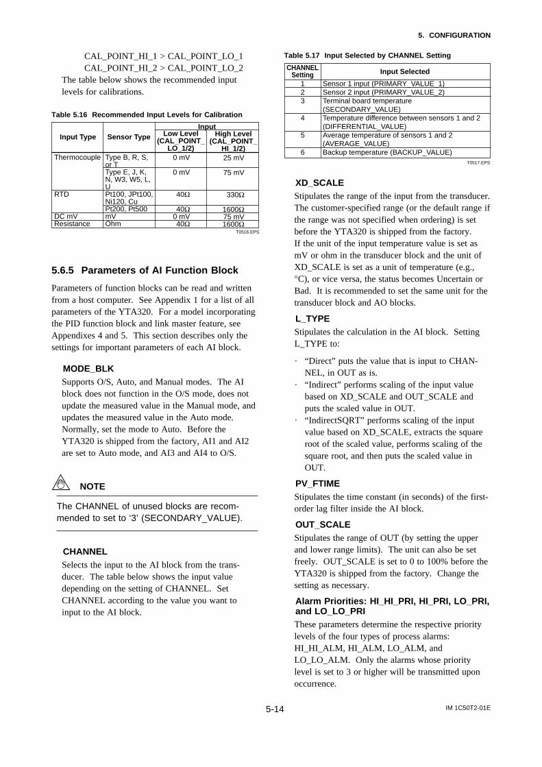
CAL_POINT_HI_1 > CAL_POINT_LO_1CAL_POINT_HI_2 > CAL_POINT_LO_2
The table below shows the recommended inputlevels for calibrations.
Table 5.16 Recommended Input Levels for Calibration
Sensor Type
Type B, R, S, or TType E, J, K, N, W3, W5, L, UPt100, JPt100, Ni120, CuPt200, Pt500mVOhm
Input Type
Thermocouple
RTD
DC mVResistance
High Level (CAL_POINT_
HI_1/2)25 mV
75 mV
330Ω
1600Ω75 mV1600Ω
Low Level (CAL_POINT_
LO_1/2)0 mV
0 mV
40Ω
40Ω0 mV40Ω
T0516.EPS
Input
5.6.5 Parameters of AI Function Block
Parameters of function blocks can be read and writtenfrom a host computer. See Appendix 1 for a list of allparameters of the YTA320. For a model incorporatingthe PID function block and link master feature, seeAppendixes 4 and 5. This section describes only thesettings for important parameters of each AI block.
MODE_BLKSupports O/S, Auto, and Manual modes. The AIblock does not function in the O/S mode, does notupdate the measured value in the Manual mode, andupdates the measured value in the Auto mode.Normally, set the mode to Auto. Before theYTA320 is shipped from the factory, AI1 and AI2are set to Auto mode, and AI3 and AI4 to O/S.
NOTE
The CHANNEL of unused blocks are recom-mended to set to ‘3’ (SECONDARY_VALUE).
CHANNELSelects the input to the AI block from the trans-ducer. The table below shows the input valuedepending on the setting of CHANNEL. SetCHANNEL according to the value you want toinput to the AI block.
Table 5.17 Input Selected by CHANNEL Setting
CHANNEL Setting Input Selected
1 Sensor 1 input (PRIMARY_VALUE_1)2 Sensor 2 input (PRIMARY_VALUE_2)3 Terminal board temperature
(SECONDARY_VALUE)4 Temperature difference between sensors 1 and 2
(DIFFERENTIAL_VALUE)5 Average temperature of sensors 1 and 2
(AVERAGE_VALUE)6 Backup temperature (BACKUP_VALUE)
T0517.EPS
XD_SCALEStipulates the range of the input from the transducer.The customer-specified range (or the default range ifthe range was not specified when ordering) is setbefore the YTA320 is shipped from the factory.If the unit of the input temperature value is set asmV or ohm in the transducer block and the unit ofXD_SCALE is set as a unit of temperature (e.g.,°C), or vice versa, the status becomes Uncertain orBad. It is recommended to set the same unit for thetransducer block and AO blocks.
L_TYPEStipulates the calculation in the AI block. SettingL_TYPE to:
· “Direct” puts the value that is input to CHAN-NEL, in OUT as is.
· “Indirect” performs scaling of the input valuebased on XD_SCALE and OUT_SCALE andputs the scaled value in OUT.
· “IndirectSQRT” performs scaling of the inputvalue based on XD_SCALE, extracts the squareroot of the scaled value, performs scaling of thesquare root, and then puts the scaled value inOUT.
PV_FTIMEStipulates the time constant (in seconds) of the first-order lag filter inside the AI block.
OUT_SCALEStipulates the range of OUT (by setting the upperand lower range limits). The unit can also be setfreely. OUT_SCALE is set to 0 to 100% before theYTA320 is shipped from the factory. Change thesetting as necessary.
Alarm Priorities: HI_HI_PRI, HI_PRI, LO_PRI,and LO_LO_PRIThese parameters determine the respective prioritylevels of the four types of process alarms:HI_HI_ALM, HI_ALM, LO_ALM, andLO_LO_ALM. Only the alarms whose prioritylevel is set to 3 or higher will be transmitted uponoccurrence.
IM 1C50T2-01E5-15
5. CONFIGURATION
These parameters are set to 1 before the YTA320 isshipped from the factory.
Table 5.18 Alarm Priority
Value Descriptions0 Alart is not notified. Alarm parameters are not updated.1 Alart is not notified. 3 to 7 Advisory alarms.8 to 15 Critical alarms.
T0518.EPS
Alarm Thresholds: HI_HI_LIM, HI_LIM,LO_LIM, and LO_LO_LIMThese parameters determine the respective thresh-olds for the four types of process alarms:HI_HI_ALM, HI_ALM, LO_ALM, andLO_LO_ALM. Before the YTA320 is shipped fromthe factory, these parameters are set to values suchthat no alarm will occur.
5.6.6 Parameters of DI Function Block
Parameters of function blocks can be read andwritten from a host computer. See Appendix 1 for alist of all parameters of the YTA320. This sectiondescribes only the settings for important parametersof each DI block.
MODE_BLKSupports O/S, Auto, and Manual modes. The DIblock does not function in the O/S mode, does notupdate the measured value in the Manual mode, andupdates the measured value in the Auto mode.Normally, set the mode to Auto. Before theYTA320 is shipped from the factory, all the DIblocks are set to O/S mode.
CHANNELSelects the input to the DI block from the trans-ducer. The table below shows the input valuedepending on the setting of CHANNEL. SetCHANNEL according to the value you want toinput to the DI block.
Table 5.19 Input Selected by CHANNEL Setting
CHANNEL Setting Input Selected 7 Limit switch 1
8 Limit switch 2 9 Limit switch 3
10 Limit switch 4T0519.EPS
PV_FTIMEStipulates the delay time (in seconds) of changingthe output value after a change of the value insidethe DI block.
DISC_PRI
Determines the priority level of the discrete alarmon the block’s output (OUT_D). The alarm will betransmitted upon occurrence only when theDISC_PRI is set at 3 or higher. This parameter isset to 1 before the YTA320 is shipped from thefactory.
Table 5.20 Alarm Priority
Value Descriptions0 Alart is not notified. Alarm parameters are not updated.1 Alart is not notified. 3 to 7 Advisory alarms.8 to 15 Critical alarms.
T0520.EPS
DISC_LIMSetpoint of the discrete alarm; when the value ofOUT_D agrees with the value set in DISC_LIM, thediscrete alarm is generated
IM 1C50T2-01E6-1
6. IN-PROCESS OPERATION
6. IN-PROCESS OPERATION
6.1 Mode TransitionAll function blocks have modes. All blocks have theirmode, expressed by MODE_BLK parameter. It is astructure of four components; Target, Actual, Permittedand Normal.
Target : Sets the operating condition of the block.Actual : Indicates the current operating condition.Permit : Indicates the operating condition that the
block is allowed to take.Normal: Indicates the operating condition that the
block will usuall y take.
When necessary condition is satisfied, actual modebecomes same to target. There is a chance that actualmode says different from target by some reason.
When the function block mode is changed toOut_Of_Service (O/S), the function block pauses and ablock alarm is issued. When the function block modeis changed to Manual (Man), the function blocksuspends updating of output values. In this case alone,it is possible to write a value to the OUT parameter ofthe block for output. Note that no parameter status canbe changed.
6.2 Generation of Alarm
6.2.1 Indication of Alarm
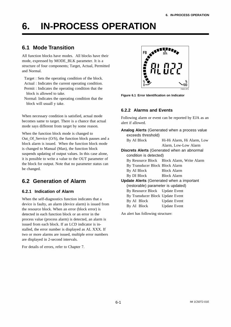
When the self-diagnostics function indicates that adevice is faulty, an alarm (device alarm) is issued fromthe resource block. When an error (block error) isdetected in each function block or an error in theprocess value (process alarm) is detected, an alarm isissued from each block. If an LCD indicator is in-stalled, the error number is displayed as AL XXX. Iftwo or more alarms are issued, multiple error numbersare displayed in 2-second intervals.
For details of errors, refer to Chapter 7.
F0601.EPS
Figure 6.1 Error Identification on Indicator
6.2.2 Alarms and Events
Following alarm or event can be reported by EJA as analert if allowed.
Analog Alerts (Generated when a process valueexceeds threshold)By AI Block Hi-Hi Alarm, Hi Alarm, Low
Alarm, Low-Low AlarmDiscrets Alerts (Generated when an abnormal
condition is detected)By Resource Block Block Alarm, Write AlarmBy Transducer Block Block AlarmBy AI Block Block AlarmBy DI Block Block Alarm
Update Alerts (Generated when a important(restorable) parameter is updated)By Resource Block Update EventBy Transducer Block Update EventBy AI Block Update EventBy AI Block Update Event
An alert has following structure:
IM 1C50T2-01E6-2
6. IN-PROCESS OPERATION
Table 6.1 Alert Object
T0602.EPS
ParameterName
Explanation
1 Block Index Index of block from which alert is generated
2 Alert Key Alert Key copied from the block
3 Standard Type
Type of the alert
4 Mfr Type Alert Name identified by manufacturer specific DD
5
1
2
3
4
5 Message Type
Reason of alert notification
1
2
3
6 Priority Priority of the alarm
7 Time Stamp Time when this alert is first detected
6
7
6
7
8 Subcode Enumerated cause of this alert
9 Value Value of referenced data
8
9
10 Relative Index
Relative index of referenced data
Static Revision
Value of static revision (ST_REV) of the block
10
8
11 Unit Index Unit code of referenced data11 9
4
5
SubindexA
nal
og
Ale
rtD
iscr
ete
Ale
rt
Up
dat
eA
lert
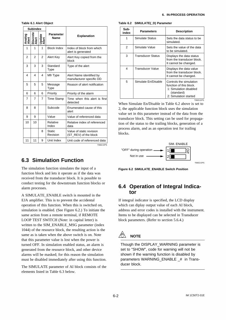
6.3 Simulation FunctionThe simulation function simulates the input of afunction block and lets it operate as if the data wasreceived from the transducer block. It is possible toconduct testing for the downstream function blocks oralarm processes.
A SIMULATE_ENABLE switch is mounted in theEJA amplifier. This is to prevent the accidentaloperation of this function. When this is switched on,simulation is enabled. (See Figure 6.2.) To initiate thesame action from a remote terminal, if REMOTELOOP TEST SWITCH (Note: in capital letter) iswritten to the SIM_ENABLE_MSG parameter (index1044) of the resource block, the resulting action is thesame as is taken when the above switch is on. Notethat this parameter value is lost when the power isturned OFF. In simulation enabled status, an alarm isgenerated from the resource block, and other devicealarms will be masked; for this reason the simulationmust be disabled immediately after using this function.
The SIMULATE parameter of AI block consists of theelements listed in Table 6.3 below.
Table 6.2 SIMULATE(_D) Parameter
T0603.EPS
Sub-index Parameters Description
1 Simulate Status Sets the data status to be simulated.
2 Simulate Value Sets the value of the data to be simulated.
3 Transducer Status Displays the data status from the transducer block. It cannot be changed.
4 Transducer Value Displays the data value from the transducer block. It cannot be changed.
5 Simulate En/Disable Controls the simulation function of this block. 1: Simulation disabled (standard) 2: Simulation started
When Simulate En/Disable in Table 6.2 above is set to2, the applicable function block uses the simulationvalue set in this parameter instead of the data from thetransducer block. This setting can be used for propaga-tion of the status to the trailing blocks, generation of aprocess alarm, and as an operation test for trailingblocks.
T0602.EPS
1
2
ON
"OFF" during operation
Not in use
SIM. ENABLE
Figure 6.2 SIMULATE_ENABLE Switch Position
6.4 Operation of Integral Indica-tor
If integral indicator is specified, the LCD displaywhich can diplay output value of each AI block,address and error codes is installed with the instrument.Items to be displayed can be selected in Transducerblock parameters. (Refer to section 5.6.4.)
NOTE
Though the DISPLAY_WARNING parameter isset to "SHOW", code for warning will not beshown if the warning function is disabled byparameters WARNING_ENABLE _# in Trans-ducer block.
IM 1C50T2-01E6-3
6. IN-PROCESS OPERATION
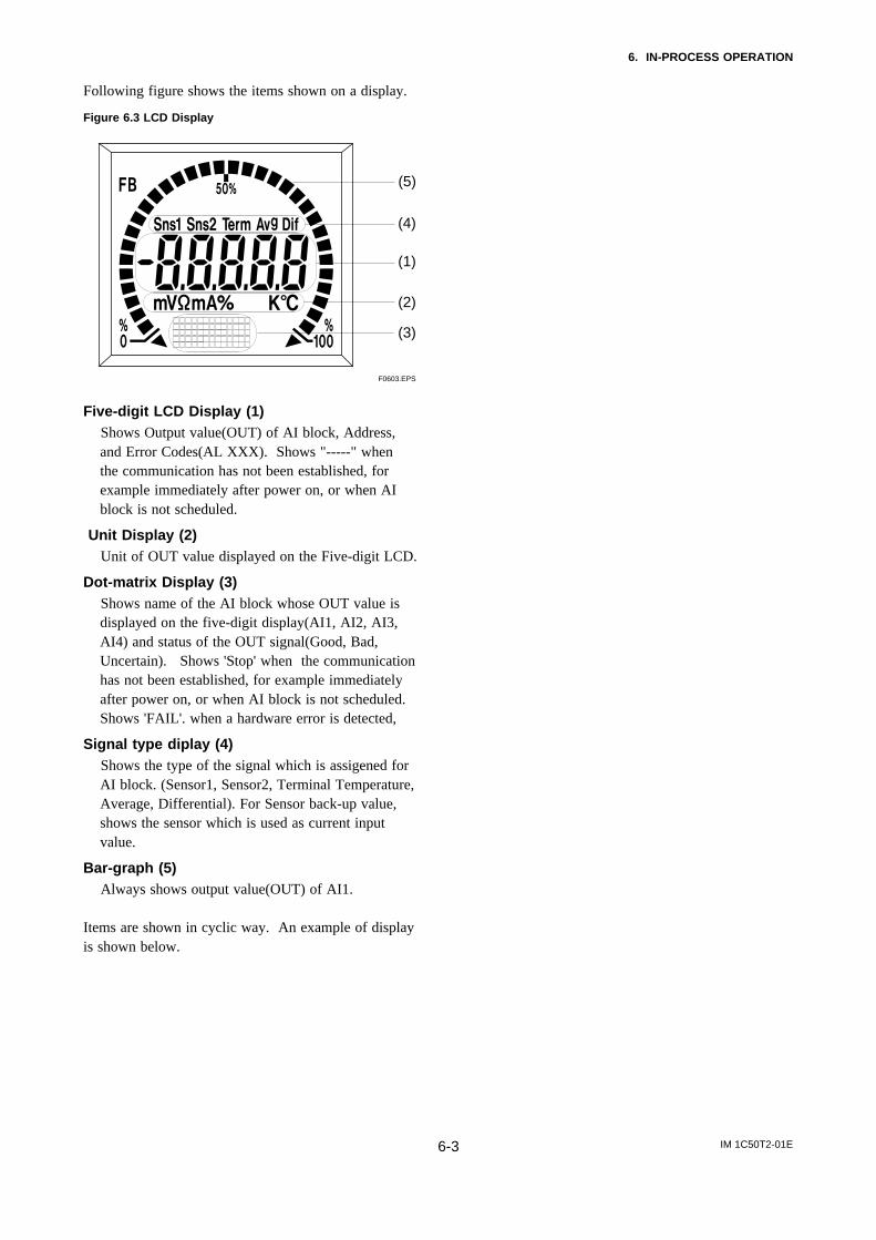
Following figure shows the items shown on a display.
Figure 6.3 LCD Display
F0603.EPS
(5)
(3)
(2)
(1)
(4)
Five-digit LCD Display (1) Shows Output value(OUT) of AI block, Address,
and Error Codes(AL XXX). Shows "-----" whenthe communication has not been established, forexample immediately after power on, or when AIblock is not scheduled.
Unit Display (2) Unit of OUT value displayed on the Five-digit LCD.
Dot-matrix Display (3) Shows name of the AI block whose OUT value is
displayed on the five-digit display(AI1, AI2, AI3,AI4) and status of the OUT signal(Good, Bad,Uncertain). Shows 'Stop' when the communicationhas not been established, for example immediatelyafter power on, or when AI block is not scheduled.Shows 'FAIL'. when a hardware error is detected,
Signal type diplay (4) Shows the type of the signal which is assigened for
AI block. (Sensor1, Sensor2, Terminal Temperature,Average, Differential). For Sensor back-up value,shows the sensor which is used as current inputvalue.
Bar-graph (5) Always shows output value(OUT) of AI1.
Items are shown in cyclic way. An example of displayis shown below.
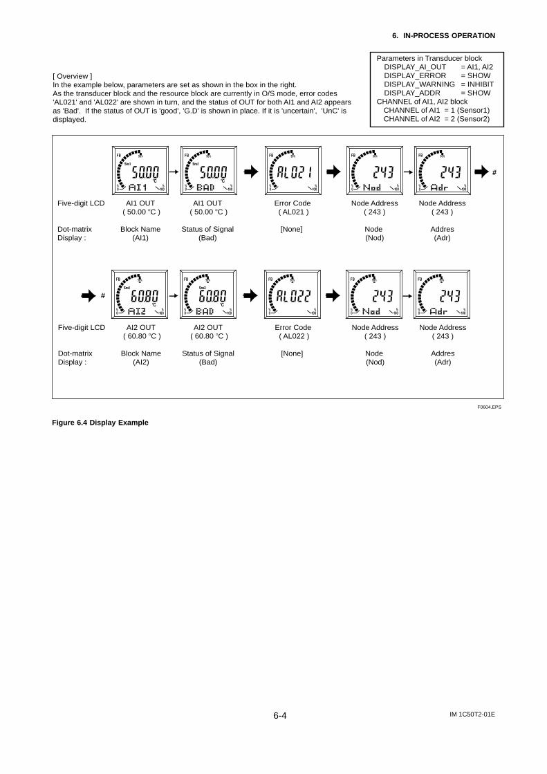
IM 1C50T2-01E6-4
6. IN-PROCESS OPERATION
Parameters in Transducer blockDISPLAY_AI_OUT = AI1, AI2DISPLAY_ERROR = SHOWDISPLAY_WARNING = INHIBITDISPLAY_ADDR = SHOW
CHANNEL of AI1, AI2 block CHANNEL of AI1 = 1 (Sensor1) CHANNEL of AI2 = 2 (Sensor2)
Five-digit LCD AI1 OUT AI1 OUT Error Code Node Address Node Address ( 50.00 C ) ( 50.00 C ) ( AL021 ) ( 243 ) ( 243 )
Dot-matrix Block Name Status of Signal [None] Node AddresDisplay : (AI1) (Bad) (Nod) (Adr)
F0604.EPS
#
[ Overview ]In the example below, parameters are set as shown in the box in the right. As the transducer block and the resource block are currently in O/S mode, error codes 'AL021' and 'AL022' are shown in turn, and the status of OUT for both AI1 and AI2 appears as 'Bad'. If the status of OUT is 'good', 'G.D' is shown in place. If it is 'uncertain', 'UnC' is displayed.
#
Five-digit LCD AI2 OUT AI2 OUT Error Code Node Address Node Address ( 60.80 C ) ( 60.80 C ) ( AL022 ) ( 243 ) ( 243 )
Dot-matrix Block Name Status of Signal [None] Node AddresDisplay : (AI2) (Bad) (Nod) (Adr)
Figure 6.4 Display Example
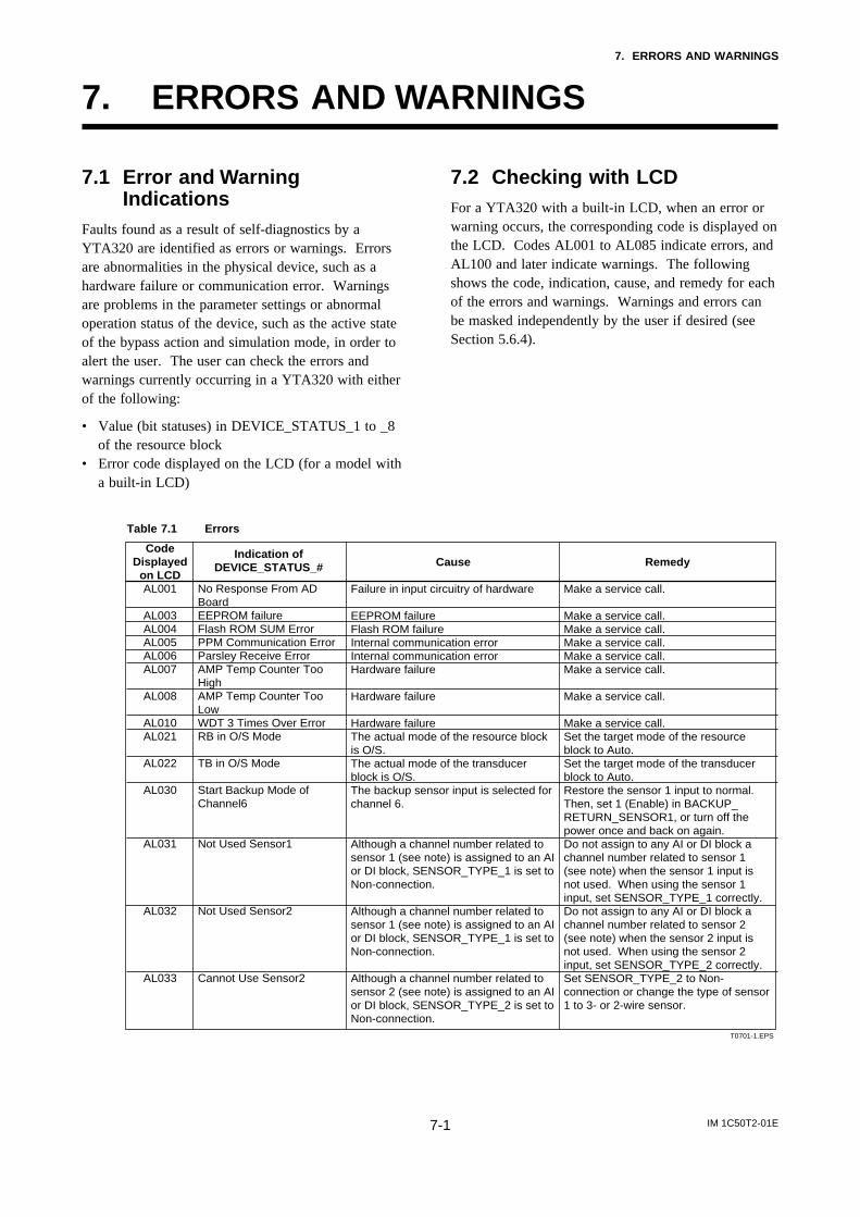
IM 1C50T2-01E7-1
7. ERRORS AND WARNINGS
7. ERRORS AND WARNINGS
7.1 Error and WarningIndications
Faults found as a result of self-diagnostics by aYTA320 are identified as errors or warnings. Errorsare abnormalities in the physical device, such as ahardware failure or communication error. Warningsare problems in the parameter settings or abnormaloperation status of the device, such as the active stateof the bypass action and simulation mode, in order toalert the user. The user can check the errors andwarnings currently occurring in a YTA320 with eitherof the following:
• Value (bit statuses) in DEVICE_STATUS_1 to _8of the resource block
• Error code displayed on the LCD (for a model witha built-in LCD)
7.2 Checking with LCDFor a YTA320 with a built-in LCD, when an error orwarning occurs, the corresponding code is displayed onthe LCD. Codes AL001 to AL085 indicate errors, andAL100 and later indicate warnings. The followingshows the code, indication, cause, and remedy for eachof the errors and warnings. Warnings and errors canbe masked independently by the user if desired (seeSection 5.6.4).
Table 7.1 Errors
Code Displayed
on LCDAL001
AL003AL004AL005AL006AL007
AL008
AL010AL021
AL022
AL030
AL031
AL032
AL033
Indication of DEVICE_STATUS_#
No Response From AD BoardEEPROM failureFlash ROM SUM ErrorPPM Communication ErrorParsley Receive ErrorAMP Temp Counter Too HighAMP Temp Counter Too LowWDT 3 Times Over ErrorRB in O/S Mode
TB in O/S Mode
Start Backup Mode of Channel6
Not Used Sensor1
Not Used Sensor2
Cannot Use Sensor2
Cause
Failure in input circuitry of hardware
EEPROM failureFlash ROM failureInternal communication errorInternal communication errorHardware failure
Hardware failure
Hardware failureThe actual mode of the resource block is O/S.The actual mode of the transducer block is O/S.The backup sensor input is selected for channel 6.
Although a channel number related to sensor 1 (see note) is assigned to an AI or DI block, SENSOR_TYPE_1 is set to Non-connection.
Although a channel number related to sensor 1 (see note) is assigned to an AI or DI block, SENSOR_TYPE_1 is set to Non-connection. Although a channel number related to sensor 2 (see note) is assigned to an AI or DI block, SENSOR_TYPE_2 is set to Non-connection.
Remedy
Make a service call.
Make a service call.Make a service call.Make a service call.Make a service call.Make a service call.
Make a service call.
Make a service call.Set the target mode of the resource block to Auto. Set the target mode of the transducer block to Auto. Restore the sensor 1 input to normal. Then, set 1 (Enable) in BACKUP_ RETURN_SENSOR1, or turn off the power once and back on again. Do not assign to any AI or DI block a channel number related to sensor 1 (see note) when the sensor 1 input is not used. When using the sensor 1 input, set SENSOR_TYPE_1 correctly. Do not assign to any AI or DI block a channel number related to sensor 2 (see note) when the sensor 2 input is not used. When using the sensor 2 input, set SENSOR_TYPE_2 correctly. Set SENSOR_TYPE_2 to Non-connection or change the type of sensor 1 to 3- or 2-wire sensor.
T0701-1.EPS
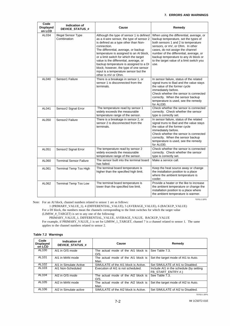
IM 1C50T2-01E7-2
7. ERRORS AND WARNINGS
Code Displayed
on LCDAL034
AL040
AL041
AL050
AL051
AL060
AL061
AL062
Indication of DEVICE_STATUS_#
Illegal Sensor Type Combination
Sensor1 Failure
Sensor2 Signal Error
Sensor2 Failure
Sensor2 Signal Error
Terminal Sensor Failure Terminal Temp Too High
Terminal Temp Too Low
Cause
Although the type of sensor 1 is defined as a 4-wire sensor, the type of sensor 2 is defined as a type other than Non-connection.The differential, average, or backup temperature is assigned to an AI block, or a limit switch for which the target value is the differential, average, or backup temperature is assigned to a DI block; however, the type of one sensor input is a temperature sensor but the other is mV or Ohm. There is a breakage in sensor 1, or sensor 1 is disconnected from the terminals.
The temperature read by sensor 1 widely exceeds the measurable temperature range of the sensor. There is a breakage in sensor 2, or sensor 2 is disconnected from the terminals.
The temperature read by sensor 2 widely exceeds the measurable temperature range of the sensor. The sensor built into the terminal board has failed.The terminal board temperature is higher than the specified high limit.
The terminal board temperature is lower than the specified low limit.
Remedy When using the differential, average, or backup temperature, set the types of both sensors 1 and 2 to temperature sensors, or mV, or Ohm. In other cases, do not assign the channel number of the differential, average, or backup temperature to any AI block or to the target value of a limit switch you use.
In sensor failure, status of the related signal truns to Bad and the value stays the value of the former cycle immediately before.Check whether the sensor is connected correctly. When the sensor backup temperature is used, see the remedy for AL030. Check whether the sensor is connected correctly. Check whether the sensor type is correctly set. In sensor failure, status of the related signal truns to Bad and the value stays the value of the former cycle immediately before.Check whether the sensor is connected correctly. When the sensor backup temperature is used, see the remedy for AL030. Check whether the sensor is connected correctly. Check whether the sensor type is correctly set. Make a service call.
Keep the heat source away or change the installation position to a place where the ambient temperature is cooler. Provide a heater or the like to increase the ambient temperature or change the installation position to a place where the ambient temperature is warmer.
T0701-2.EPS
Note: For an AI block, channel numbers related to sensor 1 are as follows:1 (PRIMARY_VALUE_1), 4 (DIFFERENTIAL_VALUE), 5 (AVERAGE_VALUE), 6 (BACKUP_VALUE)
For a DI block, the numbers mean the channels corresponding to the limit switches for which the target value(LIMSW_#_TARGET) is set to any one of the following:
PRIMARY_VALUE_1, DIFFERENTIAL_VALUE, AVERAGE_VALUE, BACKUP_VALUEFor example, if PRIMARY_VALUE_1 is set for LIMSW_1_TARGET, channel 7 is a channel related to sensor 1. The sameapplies to the channel numbers related to sensor 2.
Table 7.2 Warnings
Code Displayed
on LCDAL100
AL101
AL102AL103
AL104
AL105
AL106
Indication of DEVICE_STATUS_#
AI1 in O/S mode
AI1 in MAN mode
AI1 in Simulate ActiveAI1 Non-Scheduled
AI2 in O/S mode
AI2 in MAN mode
AI2 in Simulate active
Cause
The actual mode of the AI1 block is O/S.The actual mode of the AI1 block is Man.SIMULATE of the AI1 block is Active. Execution of AI1 is not scheduled.
The actual mode of the AI2 block is O/S.The actual mode of the AI2 block is Man. SIMULATE of the AI2 block is Active.
Remedy
See Table 7.3. Set the target mode of AI1 to Auto. Set SIMULATE of AI1 to Disabled. Include AI1 in the schedule (by setting FB_START_ENTRY.#.) See Table 7.3. Set the target mode of AI2 to Auto. Set SIMULATE of AI2 to Disabled.
T0702-1.EPS
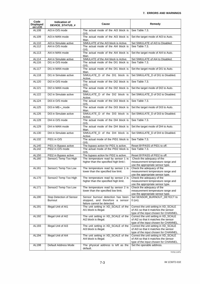
IM 1C50T2-01E7-3
7. ERRORS AND WARNINGS
Code Displayed
on LCDAL108
AL109
AL110AL112
AL113
AL114AL116
AL117
AL118
AL120
AL121
AL122
AL124
AL125
AL126
AL128
AL129
AL130
AL132
AL140AL142
AL150AL160
AL161
AL170
AL171
AL190
AL191
AL192
AL193
AL194
AL198
Indication of DEVICE_STATUS_#
AI3 in O/S mode
AI3 in MAN mode
AI3 in Simulate activeAI4 in O/S mode
AI4 in MAN mode
AI4 in Simulate activeDI1 in O/S mode
DI1 in MAN mode
DI1 in Simulate active
DI2 in O/S mode
DI2 in MAN mode
DI2 in Simulate active
DI3 in O/S mode
DI3 in ME∞_mode
DI3 in Simulate active
DI4 in O/S mode
DI4 in MAN mode DI4 in Simulate active
PID1 in O/S
PID1 in Bypass activePID2 in O/S mode
PID2 in Bypass activeSensor1 Temp Too High
Sensor1 Temp Too Low
Sensor2 Temp Too High
Sensor2 Temp Too Low
Stop Detection of Sensor Burnout
Illegal Unit of AI1
Illegal Unit of AI2
Illegal Unit of AI3
Illegal Unit of AI4
Default Address Mode
Cause
The actual mode of the AI3 block is O/S. The actual mode of the AI3 block is Man.SIMULATE of the AI3 block is Active.The actual mode of the AI4 block is O/S.The actual mode of the AI4 block is Man.SIMULATE of the AI4 block is Active. The actual mode of the DI1 block is O/S.The actual mode of the DI1 block is Man. SIMULATE_D of the DI1 block is Active.The actual mode of the DI2 block is O/S. The actual mode of the DI2 block is Man.SIMULATE_D of the DI2 block is Active.The actual mode of the DI3 block is O/S.The actual mode of the DI3 block is Man.SIMULATE_D of the DI3 block is Active.The actual mode of the DI4 block is O/S.The actual mode of the DI4 block is Man.SIMULATE_D of the DI4 block is Active. The actual mode of the PID1 block is O/S. The bypass action for PID1 is active.The actual mode of the PID2 block is O/S. The bypass action for PID2 is active.The temperature read by sensor 1 is higher than the specified high limit.\
The temperature read by sensor 1 is lower than the specified low limit.
The temperature read by sensor 2 is higher than the specified high limit.
The temperature read by sensor 2 is lower than the specified low limit.
Sensor burnout detection has been stopped, and therefore a sensor failure cannot be detected.The unit setting in XD_SCALE of the AI1 block is illegal.
The unit setting in XD_SCALE of the AI2 block is illegal.
The unit setting in XD_SCALE of the AI3 block is illegal.
The unit setting in XD_SCALE of the AI4 block is illegal.
The physical address is left as the default.
Remedy
See Table 7.3. Set the target mode of AI3 to Auto. Set SIMULATE of AI3 to Disabled. See Table 7.3. Set the target mode of AI4 to Auto. Set SIMULATE of AI4 to Disabled.See Table 7.3. Set the target mode of DI1 to Auto. Set SIMULATE_D of DI1 to Disabled. See Table 7.3. Set the target mode of DI2 to Auto. Set SIMULATE_D of DI2 to Disabled. See Table 7.3. Set the target mode of DI3 to Auto. Set SIMULATE_D of DI3 to Disabled. See Table 7.3.
Set the target mode of DI4 to Auto. Set SIMULATE_D of DI4 to Disabled. See Table 7.3. Reset BYPASS of PID1 to off. See Table 7.3. Reset BYPASS of PID2 to off. Check the adequacy of the measurement temperature range and use the appropriate sensor type. Check the adequacy of the measurement temperature range and use the appropriate sensor type. Check the adequacy of the measurement temperature range and use the appropriate sensor type. Check the adequacy of the measurement temperature range and use the appropriate sensor type. Set SENSOR_BURNOUT_DETECT to 0 (on). Correct the unit setting in XD_SCALE of AI1 so that it matches the sensor type of the input chosen for CHANNEL. Correct the unit setting in XD_SCALE of AI2 so that it matches the sensor type of the input chosen for CHANNEL. Correct the unit setting in XD_SCALE of AI3 so that it matches the sensor type of the input chosen for CHANNEL. Correct the unit setting in XD_SCALE of AI4 so that it matches the sensor type of the input chosen for CHANNEL. Set the operable address.
T0702-2.EPS
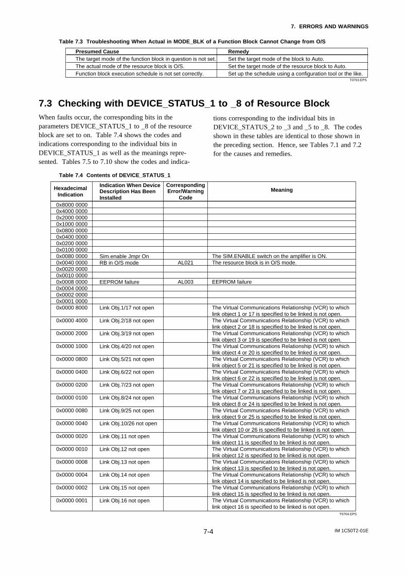
IM 1C50T2-01E7-4
7. ERRORS AND WARNINGS
Table 7.3 Troubleshooting When Actual in MODE_BLK of a Function Block Cannot Change from O/S
Presumed Cause RemedyThe target mode of the function block in question is not set. Set the target mode of the block to Auto. The actual mode of the resource block is O/S. Set the target mode of the resource block to Auto. Function block execution schedule is not set correctly. Set up the schedule using a configuration tool or the like.
T0703.EPS
7.3 Checking with DEVICE_STATUS_1 to _8 of Resource BlockWhen faults occur, the corresponding bits in theparameters DEVICE_STATUS_1 to _8 of the resourceblock are set to on. Table 7.4 shows the codes andindications corresponding to the individual bits inDEVICE_STATUS_1 as well as the meanings repre-sented. Tables 7.5 to 7.10 show the codes and indica-
tions corresponding to the individual bits inDEVICE_STATUS_2 to _3 and _5 to _8. The codesshown in these tables are identical to those shown inthe preceding section. Hence, see Tables 7.1 and 7.2for the causes and remedies.
Table 7.4 Contents of DEVICE_STATUS_1
Hexadecimal Indication
0x8000 00000x4000 00000x2000 00000x1000 00000x0800 00000x0400 00000x0200 00000x0100 00000x0080 0000 0x0040 0000 0x0020 00000x0010 00000x0008 00000x0004 00000x0002 00000x0001 00000x0000 8000
0x0000 4000
0x0000 2000
0x0000 1000
0x0000 0800
0x0000 0400
0x0000 0200
0x0000 0100
0x0000 0080
0x0000 0040
0x0000 0020 0x0000 0010
0x0000 0008
0x0000 0004
0x0000 0002
0x0000 0001
Corresponding Error/Warning
Code
AL021
AL003
Indication When Device Description Has Been Installed
Sim.enable Jmpr OnRB in O/S mode
EEPROM failure
Link Obj.1/17 not open
Link Obj.2/18 not open
Link Obj.3/19 not open
Link Obj.4/20 not open
Link Obj.5/21 not open
Link Obj.6/22 not open
Link Obj.7/23 not open
Link Obj.8/24 not open
Link Obj.9/25 not open
Link Obj.10/26 not open
Link Obj.11 not open
Link Obj.12 not open
Link Obj.13 not open
Link Obj.14 not open
Link Obj.15 not open
Link Obj.16 not open
Meaning
The SIM.ENABLE switch on the amplifier is ON.The resource block is in O/S mode.
EEPROM failure
The Virtual Communications Relationship (VCR) to which link object 1 or 17 is specified to be linked is not open. The Virtual Communications Relationship (VCR) to which link object 2 or 18 is specified to be linked is not open. The Virtual Communications Relationship (VCR) to which link object 3 or 19 is specified to be linked is not open. The Virtual Communications Relationship (VCR) to which link object 4 or 20 is specified to be linked is not open. The Virtual Communications Relationship (VCR) to which link object 5 or 21 is specified to be linked is not open. The Virtual Communications Relationship (VCR) to which link object 6 or 22 is specified to be linked is not open. The Virtual Communications Relationship (VCR) to which link object 7 or 23 is specified to be linked is not open. The Virtual Communications Relationship (VCR) to which link object 8 or 24 is specified to be linked is not open. The Virtual Communications Relationship (VCR) to which link object 9 or 25 is specified to be linked is not open. The Virtual Communications Relationship (VCR) to which link object 10 or 26 is specified to be linked is not open.The Virtual Communications Relationship (VCR) to which link object 11 is specified to be linked is not open.The Virtual Communications Relationship (VCR) to which link object 12 is specified to be linked is not open.The Virtual Communications Relationship (VCR) to which link object 13 is specified to be linked is not open. The Virtual Communications Relationship (VCR) to which link object 14 is specified to be linked is not open.The Virtual Communications Relationship (VCR) to which link object 15 is specified to be linked is not open.The Virtual Communications Relationship (VCR) to which link object 16 is specified to be linked is not open.
T0704.EPS
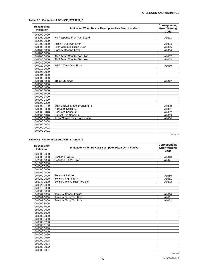
IM 1C50T2-01E7-5
7. ERRORS AND WARNINGS
Table 7.5 Contents of DEVICE_STATUS_2
Hexadecimal Indication
0x8000 00000x4000 00000x2000 00000x1000 00000x0800 00000x0400 00000x0200 00000x0100 00000x0080 00000x0040 00000x0020 00000x0010 00000x0008 00000x0004 00000x0002 00000x0001 00000x0000 80000x0000 40000x0000 20000x0000 10000x0000 08000x0000 04000x0000 02000x0000 01000x0000 00800x0000 00400x0000 00200x0000 00100x0000 00080x0000 00040x0000 00020x0000 0001
Corresponding Error/Warning
Code
AL001
AL004AL005AL006
AL007AL008
AL010
AL022
AL030AL031AL032AL033AL034
Indication When Device Description Has Been Installed
No Response From A/D Board
Flash ROM SUM ErrorPPM Communication ErrorParsley Receive Error
AMP Temp Counter Too HighAMP Temp Counter Too Low
WDT 3 Time Over Error
TB in O/S mode
Start Backup Mode of Channel 6Not Used Sensor 1Not Used Sensor 2Cannot Use Sensor 2Illegal Sensor Type Combination
T0705.EPS
Table 7.6 Contents of DEVICE_STATUS_3
Hexadecimal Indication
0x8000 00000x4000 00000x2000 00000x1000 00000x0800 00000x0400 00000x0200 00000x0100 00000x0080 00000x0040 00000x0020 00000x0010 00000x0008 00000x0004 00000x0002 00000x0001 00000x0000 80000x0000 40000x0000 20000x0000 10000x0000 08000x0000 04000x0000 02000x0000 01000x0000 00800x0000 00400x0000 00200x0000 00100x0000 00080x0000 00040x0000 00020x0000 0001
Corresponding Error/Warning
Code
AL040AL041
AL050AL051AL052
AL060AL061AL062
Indication When Device Description Has Been Installed
Sensor 1 FailureSensor 1 Signal Error
Sensor 2 FailureSensor2 Signal ErrorSensor2 Wiring RES. Too Big
Terminal Sensor FailureTerminal Temp Too HighTerminal Temp Too Low
T0706.EPS

IM 1C50T2-01E7-6
7. ERRORS AND WARNINGS
Table 7.7 Contents of DEVICE_STATUS_5
Hexadecimal Indication
0x8000 00000x4000 00000x2000 00000x1000 00000x0800 00000x0400 00000x0200 00000x0100 00000x0080 00000x0040 00000x0020 00000x0010 00000x0008 00000x0004 00000x0002 00000x0001 00000x0000 80000x0000 40000x0000 20000x0000 10000x0000 08000x0000 04000x0000 02000x0000 01000x0000 00800x0000 00400x0000 00200x0000 00100x0000 00080x0000 00040x0000 00020x0000 0001
Corresponding Error/Warning
Code
AL100AL101AL102AL103AL104AL105AL106
AL108AL109AL110
AL112AL113AL114
AL116AL117AL118
AL120AL121AL122
AL124AL125AL126
AL128AL129AL130
Indication When Device Description Has Been Installed
AI1 in O/S modeAI1 in MAN modeAI1 in Simulate activeAI1 Non-ScheduledAI2 in O/S modeAI2 in MAN modeAI2 in Simulate active
AI3 in O/S modeAI3 in MAN modeAI3 in Simulate active
AI4 in O/S modeAI4 in MAN modeAI4 in Simulate active
DI1 in O/S modeDI1 in MAN modeDI1 in Simulate active
DI2 in O/S modeDI2 in MAN modeDI2 in Simulate active
DI3 in O/S modeDI3 in MAN modeDI3 in Simulate active
DI4 in O/S modeDI4 in MAN modeDI4 in Simulate active
T0707.EPS
Table 7.8 Contents of DEVICE_STATUS_6
Hexadecimal Indication
0x8000 00000x4000 00000x2000 00000x1000 00000x0800 00000x0400 00000x0200 00000x0100 00000x0080 00000x0040 00000x0020 00000x0010 00000x0008 00000x0004 00000x0002 00000x0001 00000x0000 80000x0000 40000x0000 20000x0000 10000x0000 08000x0000 04000x0000 02000x0000 01000x0000 00800x0000 00400x0000 00200x0000 00100x0000 00080x0000 00040x0000 00020x0000 0001
Corresponding Error/Warning
Code
AL132
AL140
AL142
AL150
IIndication When Device Description Has Been Installed
PID1 in O/S mode
PID1 in Bypass active
PID2 in O/S mode
PID2 in Bypass active
T0708.EPS

IM 1C50T2-01E7-7
7. ERRORS AND WARNINGS
Table 7.9 Contents of DEVICE_STATUS_7
Hexadecimal Indication
0x8000 00000x4000 0000 0x2000 00000x1000 00000x0800 00000x0400 00000x0200 00000x0100 00000x0080 00000x0040 00000x0020 00000x0010 00000x0008 00000x0004 00000x0002 00000x0001 00000x0000 80000x0000 40000x0000 20000x0000 10000x0000 08000x0000 04000x0000 02000x0000 01000x0000 00800x0000 00400x0000 00200x0000 00100x0000 00080x0000 00040x0000 00020x0000 0001
Corresponding Error/Warning
Code
AL160AL161AL162AL163AL164
AL170AL171AL172AL173AL174
AL180
Indication When Device Description Has Been Installed
Sensor1 Temp Too HighSensor1 Temp Too LowSensor1 Constant CJC ModeSensor1 4W Wiring RES. UnbalanceSensor1 RTD/OHM 2 W Mode
Sensor2 Temp Too HighSensor2 Temp Too LowSensor2 Constant CJC Mode Sensor2 4W Wiring RES. UnbalanceSensor2 RTD/OHM 2 W Mode
Terminal Temp Too Much Change
T0709.EPS
Table 7.10 Contents of DEVICE_STATUS_8
Hexadecimal Indication
0x8000 00000x4000 00000x2000 00000x1000 00000x0800 00000x0400 00000x0200 00000x0100 00000x0080 00000x0040 00000x0020 00000x0010 00000x0008 00000x0004 00000x0002 00000x0001 00000x0000 80000x0000 40000x0000 20000x0000 10000x0000 08000x0000 04000x0000 02000x0000 01000x0000 00800x0000 00400x0000 00200x0000 00100x0000 00080x0000 00040x0000 00020x0000 0001
Corresponding Error/Warning
Code
AL190AL191AL192AL193AL194AL195
AL198
Indication When Device Description Has Been Installed
Stop Detection of Sensor BurnoutIllegal Unit of AI1Illegal Unit of AI2Illegal Unit of AI3Illegal Unit of AI4Difference Temp Too Big
Default Address Mode
T0710.EPS
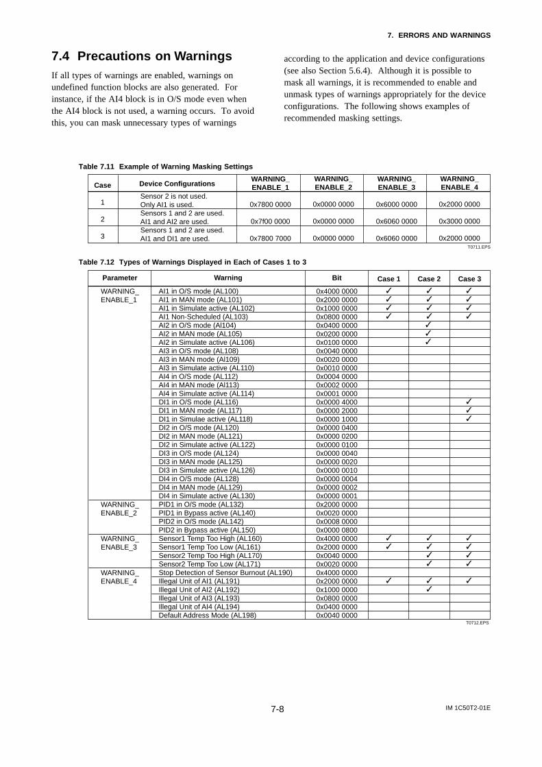
IM 1C50T2-01E7-8
7. ERRORS AND WARNINGS
7.4 Precautions on WarningsIf all types of warnings are enabled, warnings onundefined function blocks are also generated. Forinstance, if the AI4 block is in O/S mode even whenthe AI4 block is not used, a warning occurs. To avoidthis, you can mask unnecessary types of warnings
according to the application and device configurations(see also Section 5.6.4). Although it is possible tomask all warnings, it is recommended to enable andunmask types of warnings appropriately for the deviceconfigurations. The following shows examples ofrecommended masking settings.
Table 7.11 Example of Warning Masking Settings
WARNING_ENABLE_1
0x7800 0000
0x7f00 0000
0x7800 7000
WARNING_ENABLE_2
0x0000 0000
0x0000 0000
0x0000 0000
WARNING_ENABLE_3
0x6000 0000
0x6060 0000
0x6060 0000
WARNING_ENABLE_4
0x2000 0000
0x3000 0000
0x2000 0000
Device Configurations
Sensor 2 is not used.Only AI1 is used. Sensors 1 and 2 are used.AI1 and AI2 are used. Sensors 1 and 2 are used. AI1 and DI1 are used.
Case
1
2
3T0711.EPS
Table 7.12 Types of Warnings Displayed in Each of Cases 1 to 3
Warning
AI1 in O/S mode (AL100) AI1 in MAN mode (AL101) AI1 in Simulate active (AL102) AI1 Non-Scheduled (AL103)AI2 in O/S mode (Al104) AI2 in MAN mode (AL105) AI2 in Simulate active (AL106) AI3 in O/S mode (AL108) AI3 in MAN mode (Al109) AI3 in Simulate active (AL110)AI4 in O/S mode (AL112) AI4 in MAN mode (Al113) AI4 in Simulate active (AL114) DI1 in O/S mode (AL116) DI1 in MAN mode (AL117) DI1 in Simulae active (AL118)DI2 in O/S mode (AL120) DI2 in MAN mode (AL121) DI2 in Simulate active (AL122)DI3 in O/S mode (AL124) DI3 in MAN mode (AL125) DI3 in Simulate active (AL126) DI4 in O/S mode (AL128)DI4 in MAN mode (AL129) DI4 in Simulate active (AL130)PID1 in O/S mode (AL132)PID1 in Bypass active (AL140) PID2 in O/S mode (AL142) PID2 in Bypass active (AL150) Sensor1 Temp Too High (AL160) Sensor1 Temp Too Low (AL161) Sensor2 Temp Too High (AL170)Sensor2 Temp Too Low (AL171)Stop Detection of Sensor Burnout (AL190)Illegal Unit of AI1 (AL191)Illegal Unit of AI2 (AL192)Illegal Unit of AI3 (AL193)Illegal Unit of AI4 (AL194)Default Address Mode (AL198)
Bit
0x4000 00000x2000 00000x1000 00000x0800 00000x0400 00000x0200 00000x0100 00000x0040 00000x0020 00000x0010 00000x0004 00000x0002 00000x0001 00000x0000 40000x0000 20000x0000 10000x0000 04000x0000 02000x0000 01000x0000 00400x0000 00200x0000 00100x0000 00040x0000 00020x0000 00010x2000 00000x0020 00000x0008 00000x0000 08000x4000 00000x2000 00000x0040 00000x0020 00000x4000 00000x2000 00000x1000 00000x0800 00000x0400 00000x0040 0000
Parameter
WARNING_ENABLE_1
WARNING_ENABLE_2
WARNING_ENABLE_3
WARNING_ENABLE_4
Case 1 Case 2 Case 3
T0712.EPS
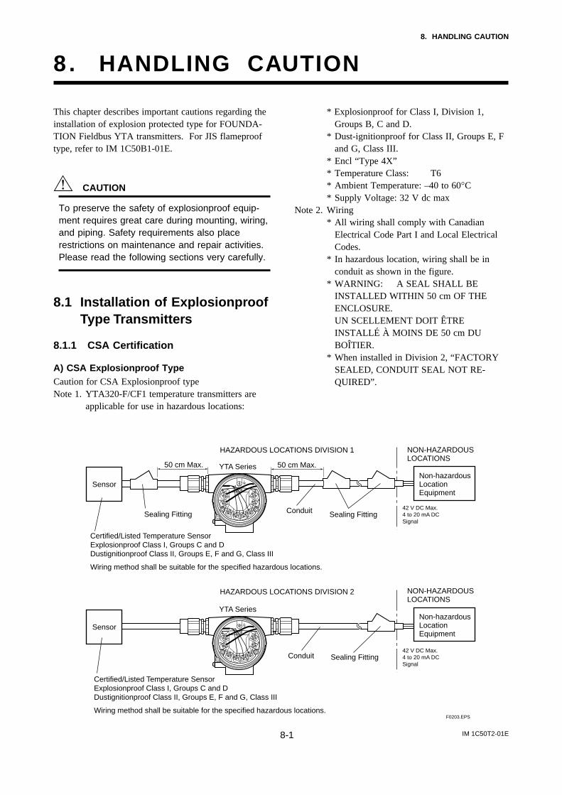
IM 1C50T2-01E8-1
8. HANDLING CAUTION
8 . HANDLING CAUTION
This chapter describes important cautions regarding theinstallation of explosion protected type for FOUNDA-TION Fieldbus YTA transmitters. For JIS flameprooftype, refer to IM 1C50B1-01E.
CAUTION
To preserve the safety of explosionproof equip-ment requires great care during mounting, wiring,and piping. Safety requirements also placerestrictions on maintenance and repair activities.Please read the following sections very carefully.
8.1 Installation of ExplosionproofType Transmitters
8.1.1 CSA Certification
A) CSA Explosionproof TypeCaution for CSA Explosionproof typeNote 1. YTA320-F/CF1 temperature transmitters are
applicable for use in hazardous locations:
* Explosionproof for Class I, Division 1,Groups B, C and D.
* Dust-ignitionproof for Class II, Groups E, Fand G, Class III.
* Encl “Type 4X”* Temperature Class: T6* Ambient Temperature: –40 to 60°C* Supply Voltage: 32 V dc max
Note 2. Wiring* All wiring shall comply with Canadian
Electrical Code Part I and Local ElectricalCodes.
* In hazardous location, wiring shall be inconduit as shown in the figure.
* WARNING: A SEAL SHALL BEINSTALLED WITHIN 50 cm OF THEENCLOSURE.UN SCELLEMENT DOIT ÊTREINSTALLÉ À MOINS DE 50 cm DUBOÎTIER.
* When installed in Division 2, “FACTORYSEALED, CONDUIT SEAL NOT RE-QUIRED”.
Sensor
Sensor
Non-hazardous Location Equipment
42 V DC Max. 4 to 20 mA DC Signal
NON-HAZARDOUS LOCATIONS
HAZARDOUS LOCATIONS DIVISION 1
50 cm Max.
Sealing FittingConduit
Non-hazardous Location Equipment
42 V DC Max. 4 to 20 mA DC Signal
NON-HAZARDOUS LOCATIONS
HAZARDOUS LOCATIONS DIVISION 2
Sealing Fitting
Sealing Fitting
50 cm Max.
Certified/Listed Temperature SensorExplosionproof Class I, Groups C and DDustignitionproof Class II, Groups E, F and G, Class III
Wiring method shall be suitable for the specified hazardous locations.
YTA Series
YTA Series
Conduit
F0203.EPS
Certified/Listed Temperature SensorExplosionproof Class I, Groups C and DDustignitionproof Class II, Groups E, F and G, Class III
Wiring method shall be suitable for the specified hazardous locations.

IM 1C50T2-01E8-2
8. HANDLING CAUTION
Note 3. Operation* Keep strictly the “WARNING” on the label
attached on the transmitter. WARNING: OPEN CIRCUIT BEFORE
REMOVING COVER.OUVRIR LE CIRCUIT AVANTD´ENLEVER LE COUVERCLE.
* Take care not to generate mechanical sparkwhen access to the instrument and peripheraldevices in hazardous location.
Note 4. Maintenance and Repair* The instrument modification or parts
replacement by other than authorizedrepresentative of Yokogawa Electric Corpo-ration is prohibited and will void CanadianStandards Explosionproof Certification.
8.1.2 CENELEC (KEMA) Certification
A) CENELEC (KEMA) Flameproof TypeCaution for CENELEC (KEMA) Flameproof TypeNote 1. Model YTA320-F/KF1 temperature transmit-
ters for potentially explosive atmospheres:* Type of Protection and Marking Code: EEx
d IIC T6Temperature Class: T6
* Ambient Temperature: –40 to 75°CNote 2. Electrical Data
* Supply voltage: 32 V dc max.Output signal: 17.5 mA max
Note 3. Installation* All wiring shall comply with local installa-
tion requirement.* The cable entry devices shall be of a
certified flameproof type, suitable for theconditions of use.
Note 4. Operation* Keep strictly the “WARNING” on the label
on the transmitter.WARNING: WAIT 5 MIN. AFTERPOWER-DISCONNECTION, BEFOREOPENING THE ENCLOSURE.WHEN THE AMBIENT TEMP. ^ 708C,USE THE HEAT-RESISTING CABLES OFHIGHER THAN 908C
* Take care not to generate mechanical sparkwhen access to the instrument and peripheraldevices in hazardous location.
Note 5. Maintenance and Repair
* The instrument modification or partsreplacement by other than authorizedrepresentative of Yokogawa Electric Corpo-ration is prohibited and will void KEMAFlameproof Certification.
8.1.3 FM Certification
A) FM Explosionproof TypeCaution for FM Explosionproof typeNote 1. Model YTA320-F /FF1 temperature transmit-
ters are applicable for use in hazardouslocations:* Explosionproof for Class I, Division 1,
Groups A, B, C, and D.* Dust-ignitionproof for Class II/III, Division
1, Groups E, F and G.* Enclosure rating: NEMA 4X.* Temperature Class: T6* Ambient Temperature: –40 to 60°C* Supply Voltage: 32 V dc max.
Note 2. Wiring* All wiring shall comply with National
Electrical Code ANSI/NEPA70 and LocalElectrical Codes.
* “FACTORY SEALED, CONDUIT SEALNOT REQUIRED”.
Note 3. Operation* Keep strictly the “WARNING” on the
nameplate attached on the transmitter.WARNING: OPEN CIRCUIT BEFOREREMOVING COVER.“FACTORY SEALED, CONDUIT SEALNOT REQUIRED”.INSTALL IN ACCORDANCE WITH THEINSTRUCTION MANUAL IM 1C50B1.
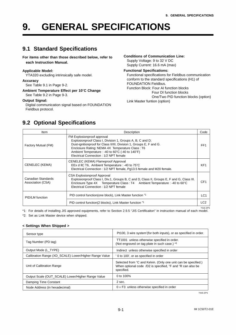
IM 1C50T2-01E9-1
9. GENERAL SPECIFICATIONS
9. GENERAL SPECIFICATIONS
9.1 Standard SpecificationsFor items other than those described below, refer to
each Instruction Manual.
Applicable Model:YTA320 excluding intrinsically safe model.
AccuracySee Table 9.1 in Page 9-2.
Ambient Temperature Effect per 10C ChangeSee Table 9.2 in Page 9-3.
Output Signal:Digital communication signal based on FOUNDATIONFieldbus protocol.
Conditions of Communication Line:Supply Voltage: 9 to 32 V DCSupply Current: 16.6 mA (max)
Functional Specifications:Functional specifications for Fieldbus communicationconform to the standard specifications (H1) ofFOUNDATION Fieldbus.Function Block: Four AI function blocks
Four DI function blocksOne/Two PID function blocks (option)
Link Master funtion (option)
9.2 Optional Specifications
Item Description Code
Factory Mutual (FM)
CSA Explosionproof ApprovalExplosionproof Class I, Div.1, Groups B, C and D, Class II, Groups E, F and G, Class III. Enclosure Type 4X Temperature Class : T4 Ambient Temperature : -40 to 60CElectrical Connection : 1/2 NPT female
CF1Canadian Standards Association (CSA)
CENELEC (KEMA) Flameproof ApprovalEEx d llC T6, Ambient Temperature : -40 to 75CElectrical Connection : 1/2 NPT female, Pg13.5 female and M20 female.
KF1
FM Explosionproof approvalExplosionproof Class I, Division 1, Groups A, B, C and D;Dust-ignitionproof for Class II/III, Division 1, Groups E, F and G.Enclosure Rating: NEMA 4X Temperature Class : T6 Ambient Temperature : -40 to 60C (-40 to 140F)Electrical Connection : 1/2 NPT female
FF1
CENELEC (KEMA)
T01E.EPS
PID/LM functionPID control function(one block), Link Master function *1 LC1
PID control function(2 blocks), Link Master function *1 LC2
*1: For details of installing JIS approved equipments, refer to Section 2.9.5 “JIS Certificaiton” in instruction manual of each model.
*2: Set as Link Master device when shipped.
< Settings When Shipped >
Tag Number (PD tag)
Output Mode (L_TYPE) Indirect unless otherwise specified in order
0 to 100%
Damping Time Constant 2 sec.
Calibration Range (XD_SCALE) Lower/Higher Range Value ’ 0 to 100’, or as specified in order
T02E.EPS
TT1001 unless otherwise specified in order. (Not engraved on tag plate in such case.) *1
Unit of Calibration RangeSelected from C and Kelvin. (Only one unit can be specified.)When optional code /D2 is specified, F and R can also be specified.
Output Scale (OUT_SCALE) Lower/Higher Range Value
Node Address (in hexadecimal) 0 × F3 unless otherwise specified in order
Sensor type Pt100, 3 wire system’(for both inputs), or as specified in order.
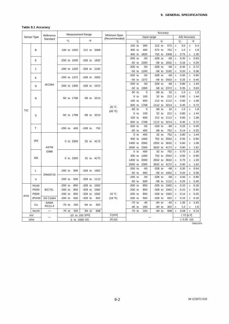
IM 1C50T2-01E9-2
9. GENERAL SPECIFICATIONS
Table 9.1 Accuracy
T0903.EPS
Sensor TypeReference Measurement Range Minimum Span
Accuracy
Standard (Recommended) Input range A/D AccuracyC F C F C F
T/C
B 100 to 1820 212 to 3308
100 to 300 212 to 572 ± 3.0 ± 5.4
300 to 400 572 to 752 ± 1.0 ± 1.8
400 to 1820 752 to 3308 ± 0.75 ± 1.35
E -200 to 1000 -328 to 1832-200 to -50 -328 to -58 ± 0.35 ± 0.63
-50 to 1000 -58 to 1832 ± 0.16 ± 0.29
J
IEC584
-200 to 1200 -328 to 2192-200 to -50 -328 to -58 ± 0.40 ± 0.72
25 C
-50 to 1200 -58 to 2192 ± 0.20 ± 0.36
K -200 to 1372 -328 to 2502
(45 F)
-200 to -50 -328 to -58 ± 0.50 ± 0.90
-50 to 1372 -58 to 2502 ± 0.25 ± 0.45
N -200 to 1300 -328 to 2372-200 to -50 -328 to -58 ± 0.80 ± 1.44
-50 to 1300 -58 to 2372 ± 0.35 ± 0.63
R -50 to 1768 -58 to 3214
-50 to 0 -58 to 32 ± 1.0 ± 1.8
0 to 100 32 to 212 ± 0.80 ± 1.44
100 to 600 212 to 1112 ± 0.60 ± 1.08
600 to 1768 1112 to 3214 ± 0.40 ± 0.72
S -50 to 1768 -58 to 3214
-50 to 0 -58 to 32 ± 1.0 ± 1.8
0 to 100 32 to 212 ± 0.80 ± 1.44
100 to 600 212 to 1112 ± 0.60 ± 1.08
600 to 1768 1112 to 3214 ± 0.40 ± 0.72
T -200 to 400 -328 to 752-200 to -50 -328 to -58 ± 0.25 ± 0.45
-50 to 400 -58 to 752 ± 0.14 ± 0.25
W3 0 to 2300 32 to 4172
0 to 400 32 to 752 ± 0.80 ± 1.44
400 to 1400 752 to 2552 ± 0.50 ± 0.90
1400 to 2000 2552 to 3632 ± 0.60 ± 1.08
ASTM 2000 to 2300 3632 to 4172 ± 0.90 ± 1.62
W5
E988
0 to 2300 32 to 4172
0 to 400 32 to 752 ± 0.70 ± 1.26
400 to 1400 752 to 2552 ± 0.50 ± 0.90
1400 to 2000 2552 to 3632 ± 0.70 ± 1.26
2000 to 2300 3632 to 4172 ± 0.90 ± 1.62
L -200 to 900 -328 to 1652-200 to -50 -328 to -58 ± 0.30 ± 0.54
DIN43710-50 to 900 -58 to 1652 ± 0.20 ± 0.36
U -200 to 600 -328 to 1112-200 to -50 -328 to -58 ± 0.50 ± 0.90
-50 to 600 -58 to 1112 ± 0.25 ± 0.45
RTD
Pt100 -200 to 850 -328 to 1562 -200 to 850 -328 to 1562 ± 0.10 ± 0.18
Pt200 IEC751 -200 to 850 -328 to 1562
10 C
-200 to 850 -328 to 1562 ± 0.22 ± 0.40
Pt500 -200 to 850 -328 to 1562
(18 F)
-200 to 850 -328 to 1562 ± 0.14 ± 0.25
JPt100 JIS C1604
SAMA RC21-4
-200 to 500 -328 to 932 -200 to 500 -328 to 932 ± 0.10 ± 0.18
-70 to -40 -94 to -40 ± 1.35 ± 2.43
-40 to 150 -40 to 302 ± 1.0 ± 1.8Cu -70 to 150 -94 to 302
mV -10 to 100 [mV] 3 [mV] ± 12 [µ V]
ohm 0 to 2000 [Ω] 20 [Ω] ± 0.35 [Ω]
Ni120 -70 to 320 -94 to 608 -70 to 320 -94 to 608 ± 0.08 ± 0.14
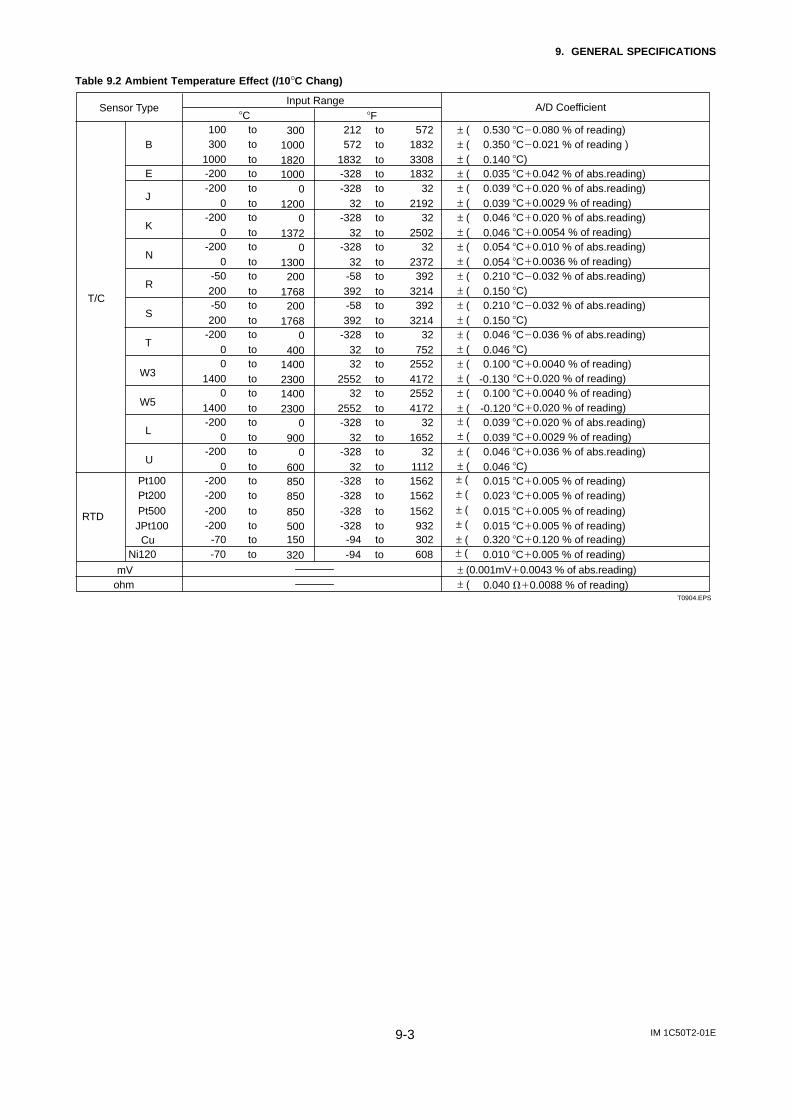
IM 1C50T2-01E9-3
9. GENERAL SPECIFICATIONS
Table 9.2 Ambient Temperature Effect (/10°C Chang)
T0904.EPS
Sensor TypeInput Range
A/D CoefficientC F
T/C
B212 to 572 ± ( 0.530 C0.080 % of reading) 572 to 1832 ± ( 0.350 C0.021 % of reading )
1832 to 3308 ± ( 0.140 C) E -328 to 1832 ± ( 0.035 C0.042 % of abs.reading)
J-328 to 32 ± ( 0.039 C0.020 % of abs.reading)
32 to 2192 ± ( 0.039 C0.0029 % of reading)
K-328 to 32 ± ( 0.046 C0.020 % of abs.reading)
32 to 2502 ± ( 0.046 C0.0054 % of reading)
N-328 to 32 ± ( 0.054 C0.010 % of abs.reading)
32 to 2372 ± ( 0.054 C0.0036 % of reading)
R-58 to 392 ± ( 0.210 C0.032 % of abs.reading)392 to 3214 ± ( 0.150 C)
S-58 to 392 ± ( 0.210 C0.032 % of abs.reading)392 to 3214 ± ( 0.150 C)
T-328 to 32 ± ( 0.046 C0.036 % of abs.reading)
32 to 752 ± ( 0.046 C)
W332 to 2552 ± ( 0.100 C0.0040 % of reading)
2552 to 4172 ± ( -0.130 C0.020 % of reading)
W532 to 2552 ± ( 0.100 C0.0040 % of reading)
2552 to 4172 ± ( -0.120 C0.020 % of reading)
L-328 to 32 ± ( 0.039 C0.020 % of abs.reading)
32 to 1652 ± ( 0.039 C0.0029 % of reading)
U-328 to 32 ± ( 0.046 C0.036 % of abs.reading)
32 to 1112 ± ( 0.046 C)
RTD
Pt100 -328 to 1562 ± ( 0.015 C0.005 % of reading) Pt200 -328 to 1562 ± ( 0.023 C0.005 % of reading)
Cu ± ( 0.320 C0.120 % of reading)-94 to 302
mV ± (0.001mV0.0043 % of abs.reading) ohm ± ( 0.040 0.0088 % of reading)
100 to 300300 to 1000
1000 to 1820-200 to 1000-200 to 0
0 to 1200-200 to 0
0 to 1372-200 to 0
0 to 1300-50 to 200200 to 1768-50 to 200200 to 1768
-200 to 00 to 4000 to 1400
1400 to 23000 to 1400
1400 to 2300-200 to 0
0 to 900-200 to 0
0 to 600-200 to 850-200 to 850
-70 to 150
Pt500 JPt100
-328 to 1562 ± ( 0.015 C0.005 % of reading)-328 to 932 ± ( 0.015 C0.005 % of reading)
-200 to 850-200 to 500
Ni120 -94 to 608 ± ( 0.010 C0.005 % of reading)-70 to 320
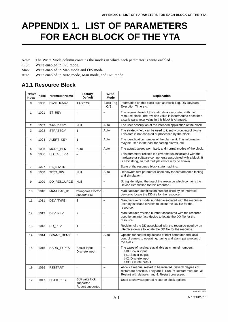
IM 1C50T2-01EA-1
APPENDIX 1. LIST OF PARAMETERS FOR EACH BLOCK OF THE YTA
APPENDIX 1. LIST OF PARAMETERSFOR EACH BLOCK OF THE YTA
Note: The Write Mode column contains the modes in which each parameter is write enabled.O/S: Write enabled in O/S mode.Man: Write enabled in Man mode and O/S mode.Auto: Write enabled in Auto mode, Man mode, and O/S mode.
A1.1 Resource Block
RelativeIndex Index ExplanationWrite
ModeFactory DefaultParameter Name
0 1000 TAG:“RS”Block Header Information on this block such as Block Tag, DD Revision, Execution Time etc.
Block Tag = O/S
1 1001 –ST_REV The revision level of the static data associated with the resource block. The revision value is incremented each time a static parameter value in this block is changed.
–
2 1002 NullTAG_DESC The user description of the intended application of the block.Auto
3 1003 1STRATEGY The strategy field can be used to identify grouping of blocks. This data is not checked or processed by the block.
Auto
4 1004 1ALERT_KEY The identification number of the plant unit. This information may be used in the host for sorting alarms, etc.
Auto
5 1005 AutoMODE_BLK The actual, target, permitted, and normal modes of the block.Auto
6 1006 –BLOCK_ERR This parameter reflects the error status associated with the hardware or software components associated with a block. It is a bit string, so that multiple errors may be shown.
–
7 1007 –RS_STATE State of the resource block state machine.–
8 1008 NullTEST_RW Read/write test parameter-used only for conformance testing and simulation.
Auto
9 1009 NullDD_RESOURCE String identifying the tag of the resource which contains the Device Description for this resource.
–
10 1010 Yokogawa Electric0x00594543
MANUFAC_ID Manufacturer identification number-used by an interface device to locate the DD file for the resource.
–
11 1011 5DEV_TYPE Manufacturer’s model number associated with the resource-used by interface devices to locate the DD file for the resource.
–
12 1012 2DEV_REV Manufacturer revision number associated with the resource-used by an interface device to locate the DD file for the resource.
–
13 1013 1DD_REV Revision of the DD associated with the resource-used by an interface device to locate the DD file for the resource.
–
14 1014 0GRANT_DENY Options for controlling access of host computer and local control panels to operating, tuning and alarm parameters of the block.
Auto
15 1015 Scalar inputDiscrete input
HARD_TYPES The types of hardware available as channel numbers.bit0: Scalar inputbit1: Scalar outputbit2: Discrete inputbit3: Discrete output
–
TA0101-1.EPS
17 1017 Soft write lock supportedReport supported
FEATURES Used to show supported resource block options.–
16 1016 –RESTART Allows a manual restart to be initiated. Several degrees of restart are possible. They are 1: Run, 2: Restart resource, 3: Restart with defaults, and 4: Restart processor.
–
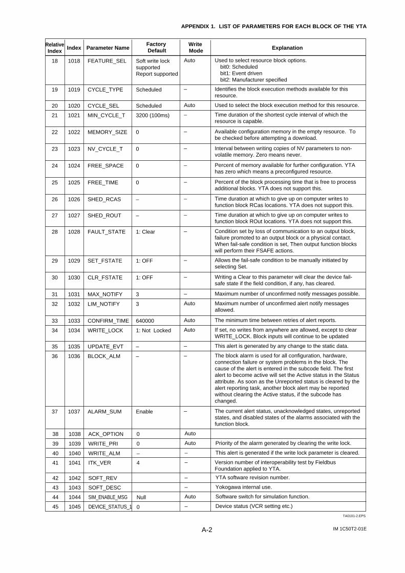
IM 1C50T2-01EA-2
APPENDIX 1. LIST OF PARAMETERS FOR EACH BLOCK OF THE YTA
20 1020 ScheduledCYCLE_SEL Used to select the block execution method for this resource.Auto
21 1021 3200 (100ms)MIN_CYCLE_T Time duration of the shortest cycle interval of which the resource is capable.
–
22 1022 0MEMORY_SIZE Available configuration memory in the empty resource. To be checked before attempting a download.
–
23 1023 0NV_CYCLE_T Interval between writing copies of NV parameters to non-volatile memory. Zero means never.
–
24 1024 0FREE_SPACE Percent of memory available for further configuration. YTA has zero which means a preconfigured resource.
–
25 1025 0FREE_TIME Percent of the block processing time that is free to process additional blocks. YTA does not support this.
–
26 1026 –SHED_RCAS Time duration at which to give up on computer writes to function block RCas locations. YTA does not support this.
–
27 1027 –SHED_ROUT Time duration at which to give up on computer writes to function block ROut locations. YTA does not support this.
–
28 1028 1: ClearFAULT_STATE Condition set by loss of communication to an output block, failure promoted to an output block or a physical contact. When fail-safe condition is set, Then output function blocks will perform their FSAFE actions.
–
29 1029 1: OFFSET_FSTATE Allows the fail-safe condition to be manually initiated by selecting Set.
–
30 1030 1: OFFCLR_FSTATE Writing a Clear to this parameter will clear the device fail-safe state if the field condition, if any, has cleared.
–
31 1031 3MAX_NOTIFY Maximum number of unconfirmed notify messages possible.–
32 1032 3LIM_NOTIFY Maximum number of unconfirmed alert notify messages allowed.
Auto
33 1033 640000CONFIRM_TIME The minimum time between retries of alert reports.Auto
34 1034 1: Not LockedWRITE_LOCK If set, no writes from anywhere are allowed, except to clear WRITE_LOCK. Block inputs will continue to be updated
Auto
35 1035 –UPDATE_EVT This alert is generated by any change to the static data.–
36 1036 –BLOCK_ALM The block alarm is used for all configuration, hardware, connection failure or system problems in the block. The cause of the alert is entered in the subcode field. The first alert to become active will set the Active status in the Status attribute. As soon as the Unreported status is cleared by the alert reporting task, another block alert may be reported without clearing the Active status, if the subcode has changed.
–
37 1037 EnableALARM_SUM The current alert status, unacknowledged states, unreported states, and disabled states of the alarms associated with the function block.
Version number of interoperability test by Fieldbus Foundation applied to YTA.
–
TA0101-2.EPS
19 1019 ScheduledCYCLE_TYPE Identifies the block execution methods available for this resource.
–
18 1018 Soft write lock supportedReport supported
FEATURE_SEL Used to select resource block options.bit0: Scheduledbit1: Event drivenbit2: Manufacturer specified
Auto
RelativeIndex Index Explanation
Write Mode
Factory DefaultParameter Name
38 1038 0
0
ACK_OPTION Auto
39 1039 0WRITE_PRI Priority of the alarm generated by clearing the write lock.Auto
–
40 1040 –WRITE_ALM This alert is generated if the write lock parameter is cleared.–
42 1042 SOFT_REV
SOFT_DESC
YTA software revision number.
43 1043 Yokogawa internal use.–
SIM_ENABLE_MSG44 1044 Software switch for simulation function.Auto
DEVICE_STATUS_145 1045 Device status (VCR setting etc.)–
41 1041 4
Null
ITK_VER –
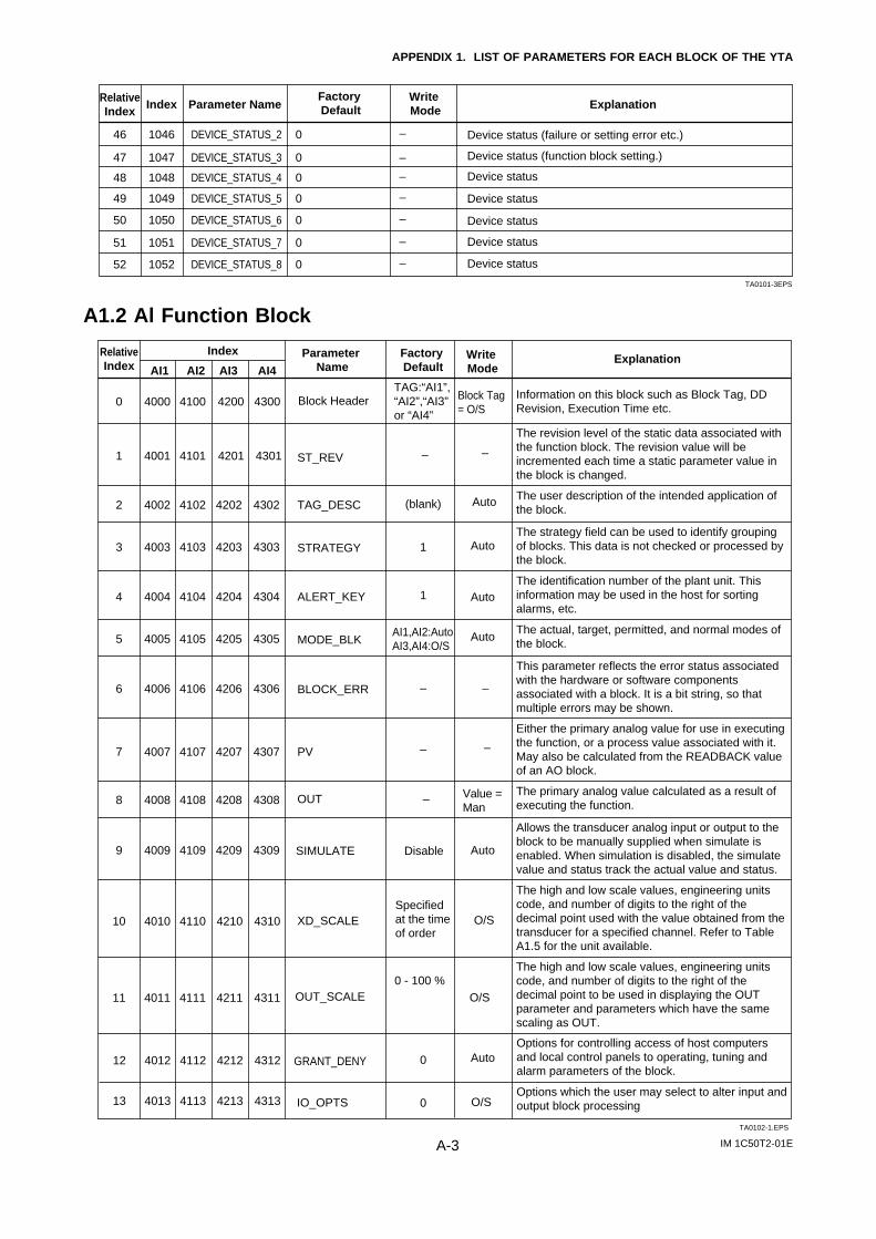
IM 1C50T2-01EA-3
APPENDIX 1. LIST OF PARAMETERS FOR EACH BLOCK OF THE YTA
46 1046 0DEVICE_STATUS_2 Device status (failure or setting error etc.)
Device status (function block setting.)
–
47 1047 0DEVICE_STATUS_3 –
48 1048 0DEVICE_STATUS_4 Device status
Device status
Device status
Device status
Device status
–
49 1049 0DEVICE_STATUS_5 –
50 1050 0DEVICE_STATUS_6 –
51 1051 0DEVICE_STATUS_7 –
52 1052 0DEVICE_STATUS_8 –
TA0101-3EPS
RelativeIndex Index Explanation
Write Mode
Factory DefaultParameter Name
A1.2 Al Function Block
RelativeIndex AI1
ExplanationWrite Mode
Factory Default
Parameter Name
0 4000 4200 4300
AI2
4100 Block Header
TA0102-1.EPS
Information on this block such as Block Tag, DD Revision, Execution Time etc.
Block Tag = O/S
1 4001 4101 4201 4301 –ST_REV
The revision level of the static data associated with the function block. The revision value will be incremented each time a static parameter value in the block is changed.
–
2 4002 4102 (blank)TAG_DESCThe user description of the intended application of the block.
Auto
Auto3 4003 4103 1STRATEGYThe strategy field can be used to identify grouping of blocks. This data is not checked or processed by the block.
4 4004 4104 1ALERT_KEYThe identification number of the plant unit. This information may be used in the host for sorting alarms, etc.
5 4005 4105 MODE_BLKThe actual, target, permitted, and normal modes of the block.
6 4006 4106 –BLOCK_ERR
This parameter reflects the error status associated with the hardware or software components associated with a block. It is a bit string, so that multiple errors may be shown.
–
7 4007 4107 –PV
Either the primary analog value for use in executing the function, or a process value associated with it.May also be calculated from the READBACK value of an AO block.
–
9 4009 4109 DisableSIMULATE
Allows the transducer analog input or output to the block to be manually supplied when simulate is enabled. When simulation is disabled, the simulate value and status track the actual value and status.
10 4010 4110 XD_SCALE
The high and low scale values, engineering units code, and number of digits to the right of the decimal point used with the value obtained from the transducer for a specified channel. Refer to Table A1.5 for the unit available.
O/S
11 4011 4111 OUT_SCALE
The high and low scale values, engineering units code, and number of digits to the right of the decimal point to be used in displaying the OUT parameter and parameters which have the same scaling as OUT.
O/S
8 4008 4108
4202 4302
4203 4303
4204 4304
4205 4305
4206 4306
4207 4307
4209 4309
4208 4308 –OUTThe primary analog value calculated as a result of executing the function.
Value = Man
12 4012 4112 0GRANT_DENY
Options for controlling access of host computers and local control panels to operating, tuning and alarm parameters of the block.
Auto
13 4013 4113
4210 4310
4211 4311
4212 4312
4213 4313 0IO_OPTSOptions which the user may select to alter input and output block processingO/S
Auto
AutoAI1,AI2:AutoAI3,AI4:O/S
Auto
TAG:“AI1”,“AI2”,“AI3” or “AI4”
Specified at the time of order
0 - 100 %
Index
AI3 AI4

IM 1C50T2-01EA-4
APPENDIX 1. LIST OF PARAMETERS FOR EACH BLOCK OF THE YTA
19 4019 4119 FIELD_VAL
TA0102-2.EPS
20 4020 4120 UPDATE_EVT
Raw value of the field device in percent of thePV range, with a status reflecting the Transducer condition, before signal characterization (L_TYPE) or filtering (PV_FTIME).
21 4021 4121 BLOCK_ALM
The block alarm is used for all configuration, hardware, connection failure or system problems in the block. The cause of the alert is entered in the subcode field. The first alert to become active will set the Active status in the Status attribute. As soon as the Unreported status is cleared by the alert reporting task, another block alert may be reported without clearing the Active status, if the subcode has changed.
22 4022 4122 ALARM_SUMThe current alert status, unacknowledged states, unreported states, and disabled states of the alarms associated with the function block.
23 4023 4123 ACK_OPTIONSelection of whether alarms associated with the block will be automatically acknowledged.
24 4024 4124 ALARM_HYSAmount the PV must return within the alarm limits before the alarm condition clears. Alarm Hysteresis is expressed as a percent of the PV span.
25 4025 4125 HI_HI_PRI Priority of the high high alarm.
26 4026 4126 HI_HI_LIM The setting for high high alarm in engineering units.
27 4027 4127 HI_PRI Priority of the high alarm.
28 4028 4128 HI_LIM The setting for high alarm in engineering units.
29 4029 4129 LO_PRI Priority of the low alarm.
30 4030 4130 LO_LIM The setting for the low alarm in engineering units.
31 4031 4131 LO_LO_PRI Priority of the low low alarm.
32 4032 4132 LO_LO_LIM The setting of the low low alarm in engineering units.
33 4033 4133 HI_HI_ALM The status for high high alarm and its associated time stamp.
34 4034 4134 HI_ALM The status for high alarm and its associated time stamp.
35 4035 4135 LO_ALM The status of the low alarm and its associated time stamp.
36 4036 4136 LO_LO_ALMThe status of the low low alarm and its associated time stamp.
This alert is generated by any change to the static data.
17 4017 4117 LOW_CUT
Limit used in square root processing. A value of zero percent of scale is used in block processing if the transducer value falls below this limit, in % of scale. This feature may be used to eliminate noise near zero for a flow sensor.
18 4018 4118 PV_FTIMETime constant of a single exponential filter for the PV, in seconds.
RelativeIndex AI1
ExplanationWrite Mode
Factory Default
Parameter NameAI2 AI3 AI4
14 4014 4114 STATUS_OPTSOptions which the user may select in the block processing of status
15 4015 4115 CHANNEL
The number of the logical hardware channel that is connected to this I/O block. This information defines the transducer to be used going to or from the physical world.
16 4016 4116
4219 4319
4220 4320
4221 4321
4222 4322
4223 4323
4224 4324
4225 4325
4226 4326
4227 4327
4228 4328
4229 4329
4230 4330
4231 4331
4232 4332
4233 4333
4234 4334
4235 4335
4236 4336
4217 4317
4218 4318
4214 4314
4215 4315
4216 4316
–
–
–
Enable
0.5%
0
+INF
0
+INF
0
–INF
0
–INF
–
–
–
–
2sec
L_TYPE
Determines if the values passed by the transducer block to the AI block may be used directly (Direct) or if the value is in different units and must be converted linearly (Indirect), or with square root (Ind Sqr Root), using the input range defined by the transducer and the associated output range.
–
–
–
–
Auto
Auto
Auto
Auto
Auto
Auto
Auto
Auto
Auto
Auto
–
–
–
–
Auto
Auto
O/S
O/S
Man
Specified at the time of order
0%
Index
0x0008Propagate Fail Fwd
AI1: 1AI2: 2AI3,AI4: 3
0xfff : unack
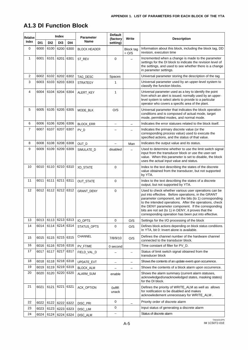
IM 1C50T2-01EA-5
APPENDIX 1. LIST OF PARAMETERS FOR EACH BLOCK OF THE YTA
A1.3 Dl Function Block
TA0103.EPS
0
1
2
3
4
5
6
7
8
9
10
11
12
13
14
15
16
17
18
19
20
21
22
23
24
6000
6001
6002
6003
6004
6005
6006
6007
6008
6009
6010
6011
6012
6013
6014
6015
6016
6017
6018
6019
6020
6021
6022
6023
6024
6100
6101
6102
6103
6104
6105
6106
6107
6108
6109
6110
6111
6112
6113
6114
6115
6116
6117
6118
6119
6120
6121
6122
6123
6124
Information about this block, including the block tag, DD revision, execution time
Incremented when a change is made to the parameter settings for the DI block to indicate the revision level of the settings, and used to see whether there is a change in parameter settings.
Universal parameter used by an upper-level system to classify the function blocks.
Universal parameter used as a key to identify the point from which an alert is issued; normally used by an upper-level system to select alerts to provide to a particular operator who covers a specific area of the plant.
Indicates the error statuses related to the block itself.
Indicates the output value and its status.
Settings for the I/O processing of the block
Time constant of filter for PV_D.
Universal parameter that indicates the block operation conditions and is composed of actual mode, target mode, permitted modes, and normal mode.
Used to determine whether to use the limit switch signal input from the transducer block or use the user-set value. When this parameter is set to disable, the block uses the actual input value and status.
Index to the text describing the states of the discrete value obtained from the transducer, but not supported by YTA.
Used to check whether various user operations can be put into effective. Before operations, in the GRANT parameter component, set the bits (to 1) corresponding to the intended operations. After the operations, check the DENY parameter component. If the corresponding bits are not set (to 1) in DENY, it proves that the corresponding operation has been put into effective.
Index to the text describing the states of a discrete output, but not supported by YTA.
Defines block actions depending on block status conditions. In YTA, bit 0: Invert alone is available.
Status of limit switch signal obtained from the transducer block
Shows the contents of an update event upon occurrence.
Shows the contents of a block alarm upon occurrence.
Defines the channel number of the hardware channel connected to the transducer block.
Shows the alarm summary (current alarm statuses, acknowledged/unacknowledged states, masking states) for the DI block.
Defines the priority of WRITE_ALM as well as allows for notification to be disabled and makes acknowledement unnecessary for WRITE_ALM .
Priority order of discrete alarm
Input status of generating a discrete alarm
Status of discrete alarm
Universal parameter storing the description of the tag
Indicates the primary discrete value (or the corresponding process value) used to execute the specified actions, and the status of that value.
DI1 DI2
RelativeIndex
IndexDescriptionWrite
Default (factorysetting)
Parameter Name
Block tag = O/S
–
–
–
Man
–
O/S
O/S
O/S
–
–
–
–
0
Spaces
1
1
O/S
–
–
–
disabled
0
0
0
0
0
7/8/9/10
0 second
–
–
–
enable
0xffff: unack
0
0
–
BLOCK HEADER
ST_REV
TAG_DESC
STRATEGY
ALERT_KEY
MODE_BLK
BLOCK_ERR
PV_D
OUT_D
SIMULATE_D
XD_STATE
OUT_STATE
GRANT_DENY
IO_OPTS
STATUS_OPTS
CHANNEL
PV_FTIME
FIELD_VAL_D
UPDATE_EVT
BLOCK_ALM
ALARM_SUM
ACK_OPTION
DISC_PRI
DISC_LIM
DISC_ALM
DI3
6200
6201
6202
6203
6204
6205
6206
6207
6208
6209
6210
6211
6212
6213
6214
6215
6216
6217
6218
6219
6220
6221
6222
6223
6224
DI4
6300
6301
6302
6303
6304
6305
6306
6307
6308
6309
6310
6311
6312
6313
6314
6315
6316
6317
6318
6319
6320
6321
6322
6323
6324
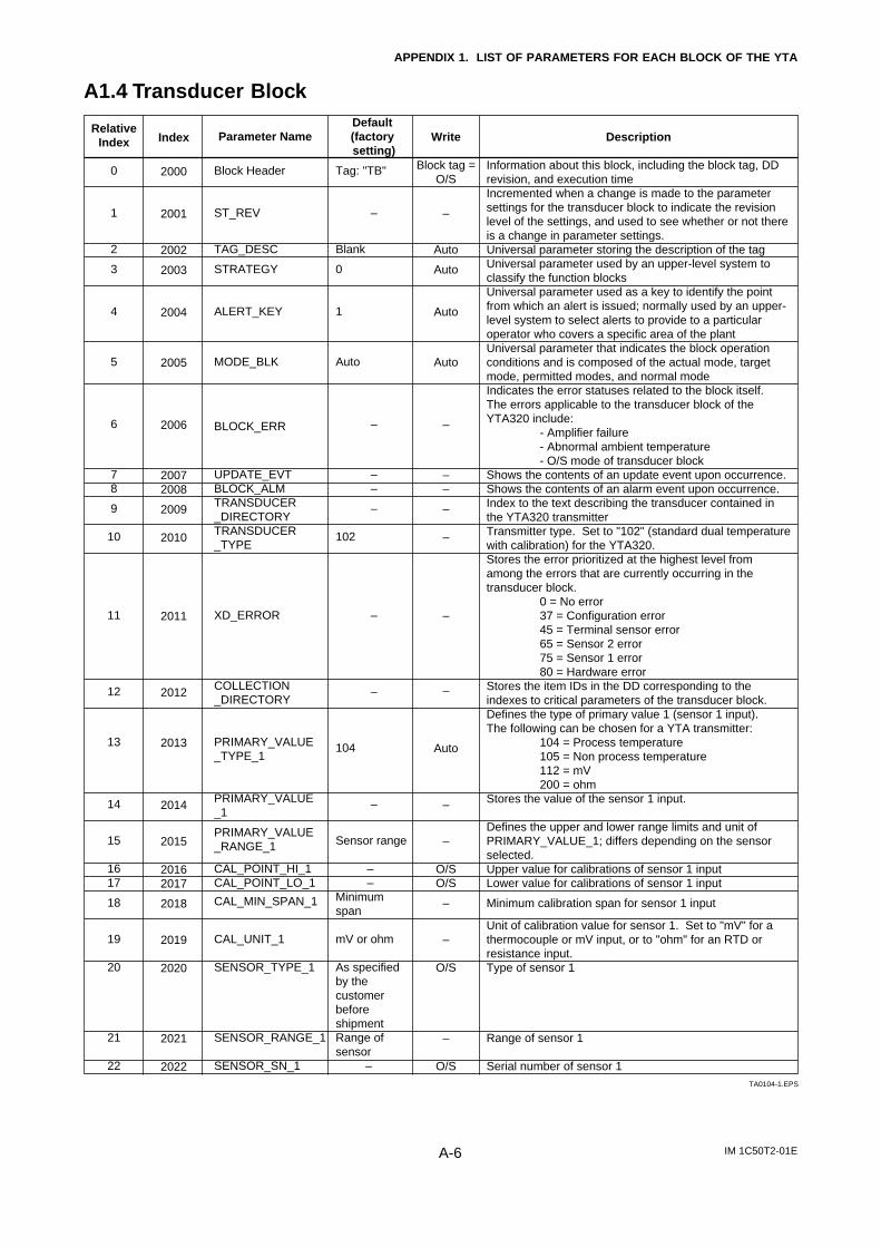
IM 1C50T2-01EA-6
APPENDIX 1. LIST OF PARAMETERS FOR EACH BLOCK OF THE YTA
A1.4 Transducer Block
TA0104-1.EPS
Index
2000
2001
2002
2003
2004
2005
2006
20072008
2009
2010
2011
2012
2013
2014
2015
20162017
2018
2019
2020
2021
2022
Description
Information about this block, including the block tag, DD revision, and execution timeIncremented when a change is made to the parameter settings for the transducer block to indicate the revision level of the settings, and used to see whether or not there is a change in parameter settings. Universal parameter storing the description of the tag Universal parameter used by an upper-level system to classify the function blocks Universal parameter used as a key to identify the point from which an alert is issued; normally used by an upper-level system to select alerts to provide to a particular operator who covers a specific area of the plant Universal parameter that indicates the block operation conditions and is composed of the actual mode, target mode, permitted modes, and normal mode Indicates the error statuses related to the block itself. The errors applicable to the transducer block of the YTA320 include:
- Amplifier failure- Abnormal ambient temperature- O/S mode of transducer block
Shows the contents of an update event upon occurrence. Shows the contents of an alarm event upon occurrence. Index to the text describing the transducer contained in the YTA320 transmitterTransmitter type. Set to "102" (standard dual temperature with calibration) for the YTA320. Stores the error prioritized at the highest level from among the errors that are currently occurring in the transducer block.
0 = No error37 = Configuration error45 = Terminal sensor error65 = Sensor 2 error75 = Sensor 1 error80 = Hardware error
Stores the item IDs in the DD corresponding to the indexes to critical parameters of the transducer block. Defines the type of primary value 1 (sensor 1 input). The following can be chosen for a YTA transmitter:
104 = Process temperature105 = Non process temperature112 = mV200 = ohm
Stores the value of the sensor 1 input. Defines the upper and lower range limits and unit of PRIMARY_VALUE_1; differs depending on the sensor selected. Upper value for calibrations of sensor 1 input Lower value for calibrations of sensor 1 input
Minimum calibration span for sensor 1 input Unit of calibration value for sensor 1. Set to "mV" for a thermocouple or mV input, or to "ohm" for an RTD or resistance input. Type of sensor 1
Range of sensor 1
Serial number of sensor 1
Write
Block tag = O/S
–
Auto
Auto
Auto
Auto
–
––
–
–
–
–
Auto
–
–
O/SO/S
–
–
O/S
–
O/S
Parameter Name
Block Header
ST_REV
TAG_DESC
STRATEGY
ALERT_KEY
MODE_BLK
BLOCK_ERR
UPDATE_EVTBLOCK_ALMTRANSDUCER_DIRECTORYTRANSDUCER_TYPE
XD_ERROR
COLLECTION_DIRECTORY
PRIMARY_VALUE_TYPE_1
PRIMARY_VALUE_1
PRIMARY_VALUE_RANGE_1
CAL_POINT_HI_1CAL_POINT_LO_1
CAL_MIN_SPAN_1
CAL_UNIT_1
SENSOR_TYPE_1
SENSOR_RANGE_1
SENSOR_SN_1
Default (factory setting)
Tag: "TB"
–
Blank
0
1
Auto
–
––
–
102
–
–
104
–
Sensor range
––
Minimum span
mV or ohm
As specified by the customer before shipmentRange of sensor
–
Relative Index
0
1
2
3
4
5
6
78
9
10
11
12
13
14
15
1617
18
19
20
21
22
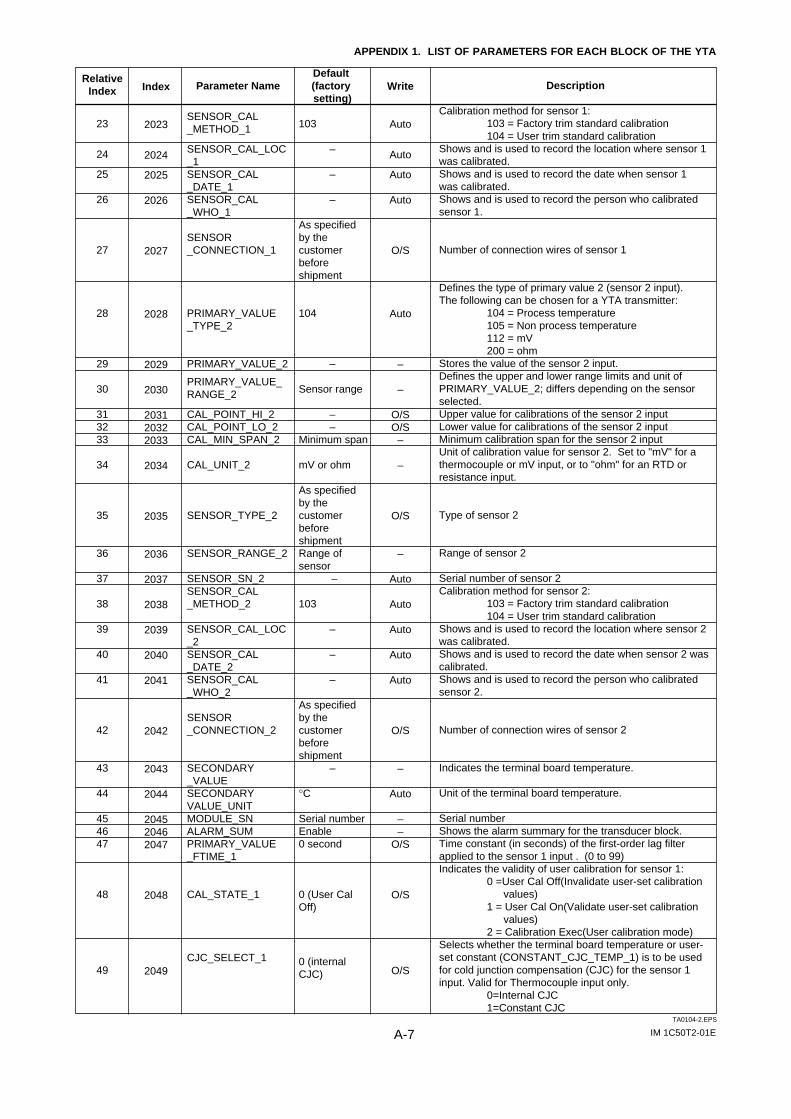
IM 1C50T2-01EA-7
APPENDIX 1. LIST OF PARAMETERS FOR EACH BLOCK OF THE YTA
TA0104-2.EPS
Index
2023
2024
2025
2026
2027
2028
2029
2030
203120322033
2034
2035
2036
2037
2038
2039
2040
2041
2042
2043
2044
204520462047
2048
2049
Description
Calibration method for sensor 1: 103 = Factory trim standard calibration104 = User trim standard calibration
Shows and is used to record the location where sensor 1 was calibrated. Shows and is used to record the date when sensor 1 was calibrated. Shows and is used to record the person who calibrated sensor 1.
Number of connection wires of sensor 1
Defines the type of primary value 2 (sensor 2 input). The following can be chosen for a YTA transmitter:
104 = Process temperature105 = Non process temperature112 = mV200 = ohm
Stores the value of the sensor 2 input. Defines the upper and lower range limits and unit of PRIMARY_VALUE_2; differs depending on the sensor selected. Upper value for calibrations of the sensor 2 input Lower value for calibrations of the sensor 2 input Minimum calibration span for the sensor 2 input Unit of calibration value for sensor 2. Set to "mV" for a thermocouple or mV input, or to "ohm" for an RTD or resistance input.
Type of sensor 2
Range of sensor 2
Serial number of sensor 2Calibration method for sensor 2:
103 = Factory trim standard calibration104 = User trim standard calibration
Shows and is used to record the location where sensor 2 was calibrated. Shows and is used to record the date when sensor 2 was calibrated. Shows and is used to record the person who calibrated sensor 2.
Number of connection wires of sensor 2
Indicates the terminal board temperature.
Unit of the terminal board temperature.
Serial numberShows the alarm summary for the transducer block. Time constant (in seconds) of the first-order lag filter applied to the sensor 1 input . (0 to 99)Indicates the validity of user calibration for sensor 1:
0 =User Cal Off(Invalidate user-set calibration values)
1 = User Cal On(Validate user-set calibration values)
2 = Calibration Exec(User calibration mode)Selects whether the terminal board temperature or user-set constant (CONSTANT_CJC_TEMP_1) is to be used for cold junction compensation (CJC) for the sensor 1 input. Valid for Thermocouple input only.
0=Internal CJC 1=Constant CJC
Write
Auto
Auto
Auto
Auto
O/S
Auto
–
–
O/SO/S
–
–
O/S
–
Auto
Auto
Auto
Auto
Auto
O/S
–
Auto
––
O/S
O/S
O/S
Parameter Name
SENSOR_CAL_METHOD_1
SENSOR_CAL_LOC_1SENSOR_CAL_DATE_1SENSOR_CAL_WHO_1
SENSOR_CONNECTION_1
PRIMARY_VALUE_TYPE_2
PRIMARY_VALUE_2
PRIMARY_VALUE_RANGE_2
CAL_POINT_HI_2CAL_POINT_LO_2CAL_MIN_SPAN_2
CAL_UNIT_2
SENSOR_TYPE_2
SENSOR_RANGE_2
SENSOR_SN_2SENSOR_CAL_METHOD_2
SENSOR_CAL_LOC_2SENSOR_CAL_DATE_2SENSOR_CAL_WHO_2
SENSOR_CONNECTION_2
SECONDARY_VALUESECONDARYVALUE_UNITMODULE_SNALARM_SUMPRIMARY_VALUE_FTIME_1
CAL_STATE_1
CJC_SELECT_1
Default (factory setting)
103
–
–
–
As specified by the customer before shipment
104
–
Sensor range
––
Minimum span
mV or ohm
As specified by the customer before shipmentRange of sensor
–
103
–
–
–
As specified by the customer before shipment
–
°C
Serial numberEnable0 second
0 (User Cal Off)
0 (internal CJC)
Relative Index
23
24
25
26
27
28
29
30
313233
34
35
36
37
38
39
40
41
42
43
44
454647
48
49
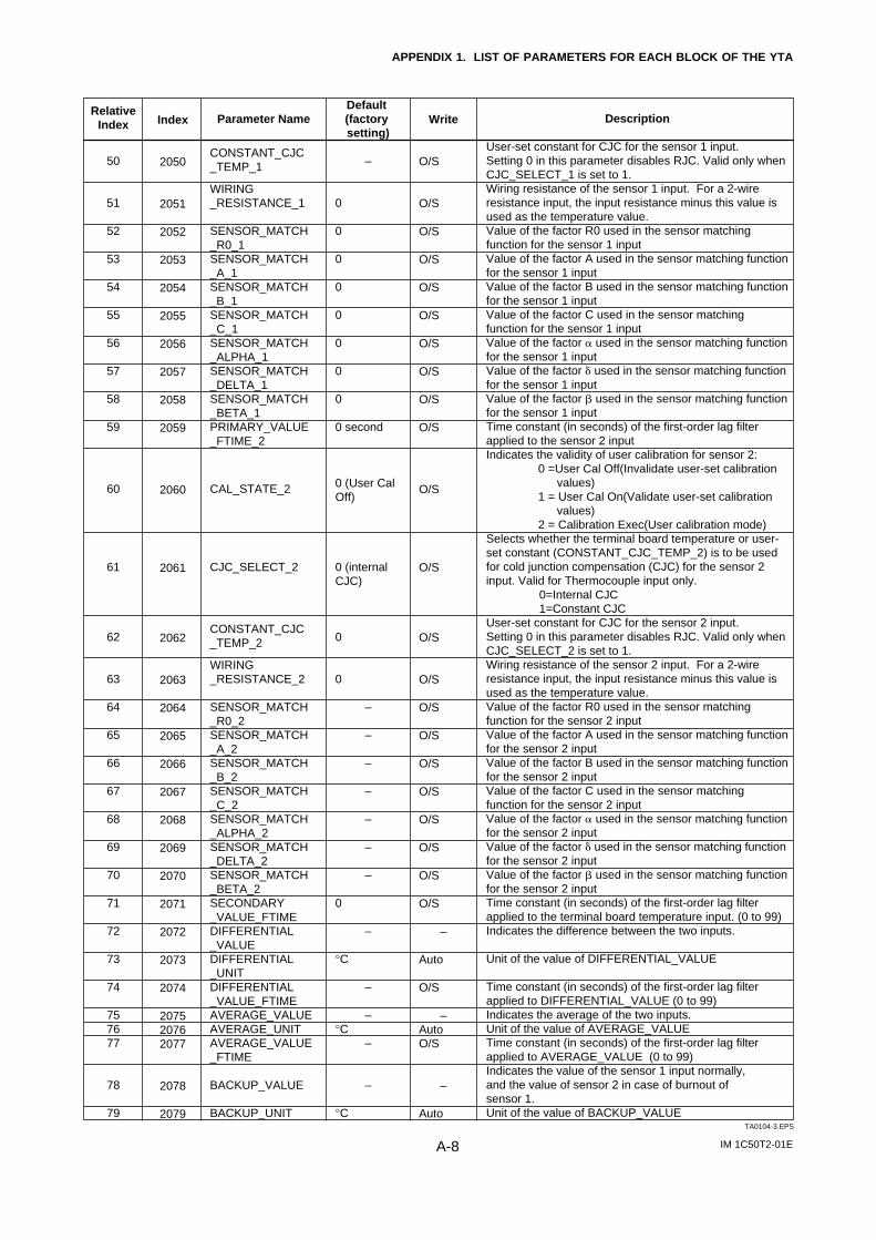
IM 1C50T2-01EA-8
APPENDIX 1. LIST OF PARAMETERS FOR EACH BLOCK OF THE YTA
TA0104-3.EPS
Index
2050
2051
2052
2053
2054
2055
2056
2057
2058
2059
2060
2061
2062
2063
2064
2065
2066
2067
2068
2069
2070
2071
2072
2073
2074
207520762077
2078
2079
Description
User-set constant for CJC for the sensor 1 input. Setting 0 in this parameter disables RJC. Valid only when CJC_SELECT_1 is set to 1. Wiring resistance of the sensor 1 input. For a 2-wire resistance input, the input resistance minus this value is used as the temperature value. Value of the factor R0 used in the sensor matching function for the sensor 1 inputValue of the factor A used in the sensor matching function for the sensor 1 inputValue of the factor B used in the sensor matching function for the sensor 1 inputValue of the factor C used in the sensor matching function for the sensor 1 inputValue of the factor used in the sensor matching function for the sensor 1 inputValue of the factor used in the sensor matching function for the sensor 1 inputValue of the factor used in the sensor matching function for the sensor 1 inputTime constant (in seconds) of the first-order lag filter applied to the sensor 2 inputIndicates the validity of user calibration for sensor 2:
0 =User Cal Off(Invalidate user-set calibration values)
1 = User Cal On(Validate user-set calibration values)
2 = Calibration Exec(User calibration mode)Selects whether the terminal board temperature or user-set constant (CONSTANT_CJC_TEMP_2) is to be used for cold junction compensation (CJC) for the sensor 2 input. Valid for Thermocouple input only.
0=Internal CJC 1=Constant CJC
User-set constant for CJC for the sensor 2 input. Setting 0 in this parameter disables RJC. Valid only when CJC_SELECT_2 is set to 1. Wiring resistance of the sensor 2 input. For a 2-wire resistance input, the input resistance minus this value is used as the temperature value. Value of the factor R0 used in the sensor matching function for the sensor 2 inputValue of the factor A used in the sensor matching function for the sensor 2 inputValue of the factor B used in the sensor matching function for the sensor 2 inputValue of the factor C used in the sensor matching function for the sensor 2 inputValue of the factor used in the sensor matching function for the sensor 2 inputValue of the factor used in the sensor matching function for the sensor 2 inputValue of the factor used in the sensor matching function for the sensor 2 inputTime constant (in seconds) of the first-order lag filter applied to the terminal board temperature input. (0 to 99)Indicates the difference between the two inputs. Unit of the value of DIFFERENTIAL_VALUE
Time constant (in seconds) of the first-order lag filter applied to DIFFERENTIAL_VALUE (0 to 99)Indicates the average of the two inputs. Unit of the value of AVERAGE_VALUETime constant (in seconds) of the first-order lag filter applied to AVERAGE_VALUE (0 to 99)Indicates the value of the sensor 1 input normally, and the value of sensor 2 in case of burnout of sensor 1. Unit of the value of BACKUP_VALUE
Write
O/S
O/S
O/S
O/S
O/S
O/S
O/S
O/S
O/S
O/S
O/S
O/S
O/S
O/S
O/S
O/S
O/S
O/S
O/S
O/S
O/S
O/S
–
Auto
O/S
–AutoO/S
–
Auto
Parameter Name
CONSTANT_CJC_TEMP_1
WIRING_RESISTANCE_1
SENSOR_MATCH_R0_1SENSOR_MATCH_A_1SENSOR_MATCH_B_1SENSOR_MATCH_C_1SENSOR_MATCH_ALPHA_1SENSOR_MATCH_DELTA_1SENSOR_MATCH_BETA_1PRIMARY_VALUE_FTIME_2
CAL_STATE_2
CJC_SELECT_2
CONSTANT_CJC_TEMP_2
WIRING_RESISTANCE_2
SENSOR_MATCH_R0_2SENSOR_MATCH_A_2SENSOR_MATCH_B_2SENSOR_MATCH_C_2SENSOR_MATCH_ALPHA_2SENSOR_MATCH_DELTA_2SENSOR_MATCH_BETA_2SECONDARY_VALUE_FTIMEDIFFERENTIAL_VALUEDIFFERENTIAL_UNITDIFFERENTIAL_VALUE_FTIMEAVERAGE_VALUEAVERAGE_UNITAVERAGE_VALUE_FTIME
BACKUP_VALUE
BACKUP_UNIT
Default (factory setting)
–
0
0
0
0
0
0
0
0
0 second
0 (User Cal Off)
0 (internal CJC)
0
0
–
–
–
–
–
–
–
0
–
°C
–
–°C
–
–
°C
Relative Index
50
51
52
53
54
55
56
57
58
59
60
61
62
63
64
65
66
67
68
69
70
71
72
73
74
757677
78
79
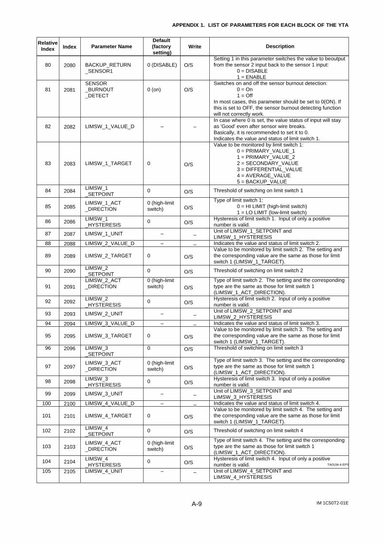
IM 1C50T2-01EA-9
APPENDIX 1. LIST OF PARAMETERS FOR EACH BLOCK OF THE YTA
TA0104-4.EPS
Index
2080
2081
2082
2083
2084
2085
2086
2087
2088
2089
2090
2091
2092
2093
2094
2095
2096
2097
2098
2099
2100
2101
2102
2103
2104
2105
Description
Setting 1 in this parameter switches the value to beoutput from the sensor 2 input back to the sensor 1 input:
0 = DISABLE1 = ENABLE
Switches on and off the sensor burnout detection: 0 = On1 = Off
In most cases, this parameter should be set to 0(ON). If this is set to OFF, the sensor burnout detecting function will not correctly work.In case where 0 is set, the value status of input will stay as 'Good' even after sensor wire breaks. Basically, it is recommended to set it to 0. Indicates the value and status of limit switch 1. Value to be monitored by limit switch 1:
0 = PRIMARY_VALUE_11 = PRIMARY_VALUE_22 = SECONDARY_VALUE3 = DIFFERENTIAL_VALUE4 = AVERAGE_VALUE5 = BACKUP_VALUE
Threshold of switching on limit switch 1
Type of limit switch 1: 0 = HI LIMIT (high-limit switch)1 = LO LIMIT (low-limit switch)
Hysteresis of limit switch 1. Input of only a positive number is valid. Unit of LIMSW_1_SETPOINT and LIMSW_1_HYSTERESIS Indicates the value and status of limit switch 2. Value to be monitored by limit switch 2. The setting and the corresponding value are the same as those for limit switch 1 (LIMSW_1_TARGET).
Threshold of switching on limit switch 2
Type of limit switch 2. The setting and the corresponding type are the same as those for limit switch 1 (LIMSW_1_ACT_DIRECTION). Hysteresis of limit switch 2. Input of only a positive number is valid. Unit of LIMSW_2_SETPOINT and LIMSW_2_HYSTERESIS Indicates the value and status of limit switch 3. Value to be monitored by limit switch 3. The setting and the corresponding value are the same as those for limit switch 1 (LIMSW_1_TARGET). Threshold of switching on limit switch 3
Type of limit switch 3. The setting and the corresponding type are the same as those for limit switch 1 (LIMSW_1_ACT_DIRECTION). Hysteresis of limit switch 3. Input of only a positive number is valid.Unit of LIMSW_3_SETPOINT and LIMSW_3_HYSTERESIS Indicates the value and status of limit switch 4. Value to be monitored by limit switch 4. The setting and the corresponding value are the same as those for limit switch 1 (LIMSW_1_TARGET).
Threshold of switching on limit switch 4
Type of limit switch 4. The setting and the corresponding type are the same as those for limit switch 1 (LIMSW_1_ACT_DIRECTION). Hysteresis of limit switch 4. Input of only a positive number is valid.Unit of LIMSW_4_SETPOINT and LIMSW_4_HYSTERESIS
Write
O/S
O/S
–
O/S
O/S
O/S
O/S
–
–
O/S
O/S
O/S
O/S
–
–
O/S
O/S
O/S
O/S
–
–
O/S
O/S
O/S
O/S
–
Parameter Name
BACKUP_RETURN_SENSOR1
SENSOR_BURNOUT_DETECT
LIMSW_1_VALUE_D
LIMSW_1_TARGET
LIMSW_1_SETPOINT
LIMSW_1_ACT_DIRECTION
LIMSW_1_HYSTERESIS
LIMSW_1_UNIT
LIMSW_2_VALUE_D
LIMSW_2_TARGET
LIMSW_2_SETPOINTLIMSW_2_ACT_DIRECTION
LIMSW_2_HYSTERESIS
LIMSW_2_UNIT
LIMSW_3_VALUE_D
LIMSW_3_TARGET
LIMSW_3_SETPOINT
LIMSW_3_ACT_DIRECTION
LIMSW_3_HYSTERESIS
LIMSW_3_UNIT
LIMSW_4_VALUE_D
LIMSW_4_TARGET
LIMSW_4_SETPOINT
LIMSW_4_ACT_DIRECTION
LIMSW_4_HYSTERESISLIMSW_4_UNIT
Default (factory setting)
0 (DISABLE)
0 (on)
–
0
0
0 (high-limit switch)
0
–
–
0
0
0 (high-limit switch)
0
–
–
0
0
0 (high-limit switch)
0
–
–
0
0
0 (high-limit switch)
0
–
Relative Index
80
81
82
83
84
85
86
87
88
89
90
91
92
93
94
95
96
97
98
99
100
101
102
103
104
105
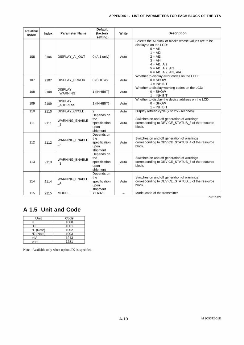
IM 1C50T2-01EA-10
APPENDIX 1. LIST OF PARAMETERS FOR EACH BLOCK OF THE YTA
TA0104-5.EPS
Index
2106
2107
2108
2109
2110
2111
2112
2113
2114
2115
Description
Selects the AI block or blocks whose values are to be displayed on the LCD:
0 = AI11 = AI22 = AI33 = AI44 = AI1, AI25 = AI1, AI2, AI36 = AI1, AI2, AI3, AI4
Whether to display error codes on the LCD: 0 = SHOW1 = INHIBIT
Whether to display warning codes on the LCD: 0 = SHOW1 = INHIBIT
Whether to display the device address on the LCD: 0 = SHOW1 = INHIBIT
Display refresh cycle (2 to 255 seconds)
Switches on and off generation of warnings corresponding to DEVICE_STATUS_3 of the resource block.
Switches on and off generation of warnings corresponding to DEVICE_STATUS_4 of the resource block.
Switches on and off generation of warnings corresponding to DEVICE_STATUS_5 of the resource block.
Switches on and off generation of warnings corresponding to DEVICE_STATUS_6 of the resource block.
Model code of the transmitter
Write
Auto
Auto
Auto
Auto
Auto
Auto
Auto
Auto
Auto
–
Parameter Name
DISPLAY_AI_OUT
DISPLAY_ERROR
DISPLAY_WARNING
DISPLAY_ADDRESS
DISPLAY_CYCLE
WARNING_ENABLE_1
WARNING_ENABLE_2
WARNING_ENABLE_3
WARNING_ENABLE_4
MODEL
Default (factory setting)
0 (AI1 only)
0 (SHOW)
1 (INHIBIT)
1 (INHIBIT)
2Depends onthespecification uponshipmentDepends onthespecification uponshipmentDepends onthe specificationuponshipmentDepends onthespecification uponshipmentYTA320
Relative Index
106
107
108
109
110
111
112
113
114
115
A 1.5 Unit and CodeUnit Code
K 1000°C 1001°F (Note) 1002°R (Note) 1003mV 1243ohm 1281
Note : Available only when option /D2 is specified.
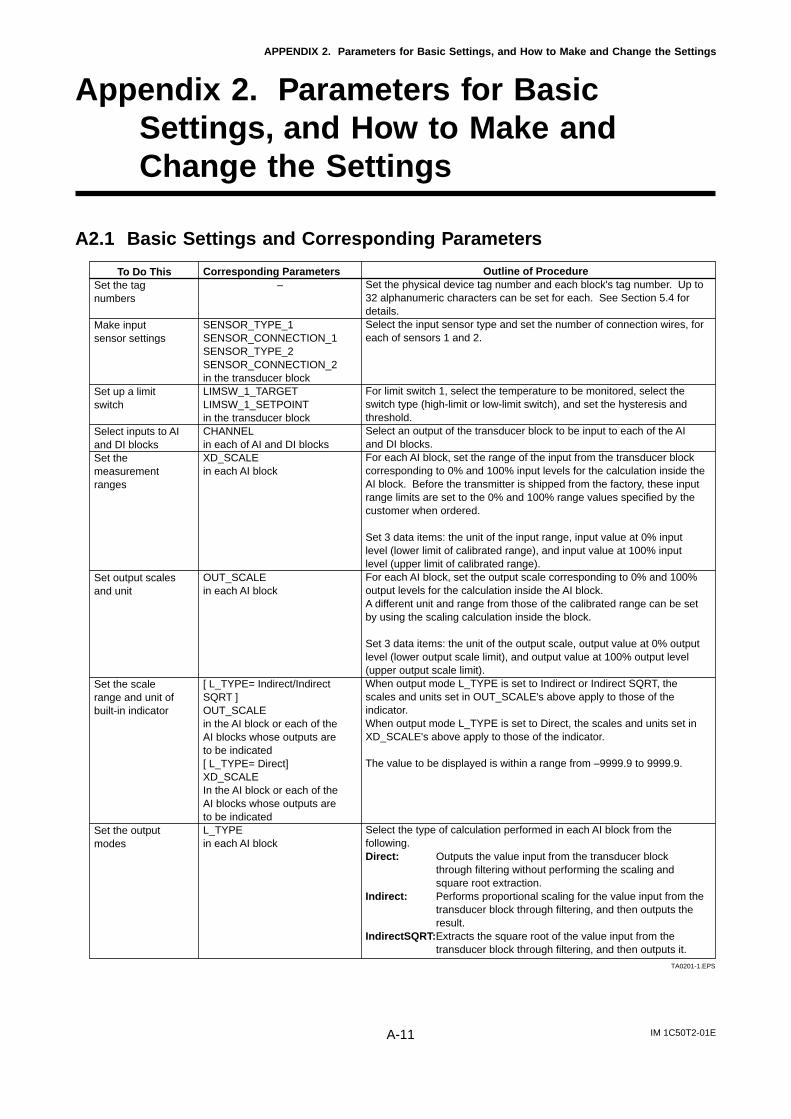
IM 1C50T2-01EA-11
APPENDIX 2. Parameters for Basic Settings, and How to Make and Change the Settings
Appendix 2. Parameters for BasicSettings, and How to Make andChange the Settings
A2.1 Basic Settings and Corresponding Parameters
TA0201-1.EPS
To Do ThisSet the tag numbers
Make input sensor settings
Set up a limit switch
Select inputs to AI and DI blocksSet the measurement ranges
Set output scales and unit
Set the scale range and unit of built-in indicator
Set the output modes
Corresponding Parameters–
SENSOR_TYPE_1SENSOR_CONNECTION_1SENSOR_TYPE_2SENSOR_CONNECTION_2in the transducer blockLIMSW_1_TARGETLIMSW_1_SETPOINTin the transducer blockCHANNEL in each of AI and DI blocksXD_SCALEin each AI block
OUT_SCALEin each AI block
[ L_TYPE= Indirect/Indirect SQRT ]OUT_SCALEin the AI block or each of the AI blocks whose outputs are to be indicated[ L_TYPE= Direct]XD_SCALE In the AI block or each of the AI blocks whose outputs are to be indicatedL_TYPEin each AI block
Outline of ProcedureSet the physical device tag number and each block's tag number. Up to 32 alphanumeric characters can be set for each. See Section 5.4 for details. Select the input sensor type and set the number of connection wires, for each of sensors 1 and 2.
For limit switch 1, select the temperature to be monitored, select the switch type (high-limit or low-limit switch), and set the hysteresis and threshold. Select an output of the transducer block to be input to each of the AI and DI blocks. For each AI block, set the range of the input from the transducer block corresponding to 0% and 100% input levels for the calculation inside the AI block. Before the transmitter is shipped from the factory, these input range limits are set to the 0% and 100% range values specified by the customer when ordered. Set 3 data items: the unit of the input range, input value at 0% input level (lower limit of calibrated range), and input value at 100% input level (upper limit of calibrated range). For each AI block, set the output scale corresponding to 0% and 100% output levels for the calculation inside the AI block. A different unit and range from those of the calibrated range can be set by using the scaling calculation inside the block.
Set 3 data items: the unit of the output scale, output value at 0% output level (lower output scale limit), and output value at 100% output level (upper output scale limit). When output mode L_TYPE is set to Indirect or Indirect SQRT, the scales and units set in OUT_SCALE's above apply to those of the indicator. When output mode L_TYPE is set to Direct, the scales and units set in XD_SCALE's above apply to those of the indicator.
The value to be displayed is within a range from –9999.9 to 9999.9.
Select the type of calculation performed in each AI block from the following. Direct: Outputs the value input from the transducer block
through filtering without performing the scaling and square root extraction.
Indirect: Performs proportional scaling for the value input from the transducer block through filtering, and then outputs the result.
IndirectSQRT:Extracts the square root of the value input from the transducer block through filtering, and then outputs it.
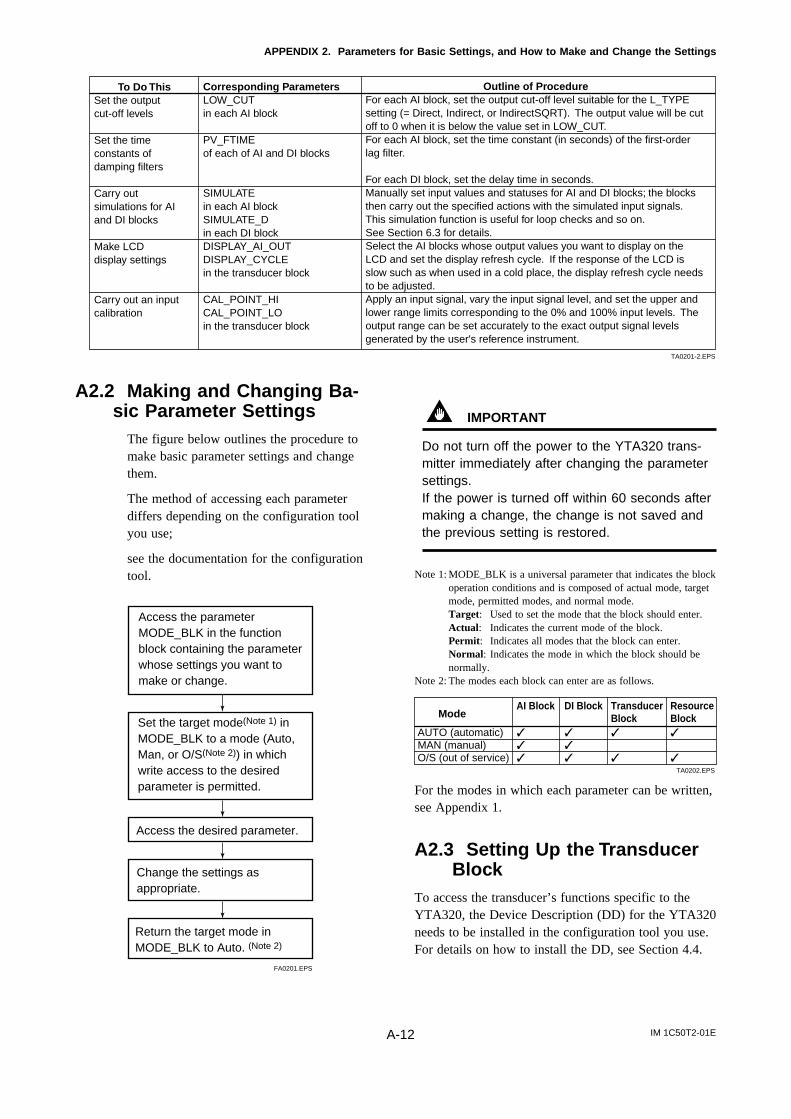
IM 1C50T2-01EA-12
APPENDIX 2. Parameters for Basic Settings, and How to Make and Change the Settings
TA0201-2.EPS
To Do ThisSet the output cut-off levels
Set the time constants of damping filters Carry out simulations for AI and DI blocks
Make LCD display settings
Carry out an input calibration
Corresponding ParametersLOW_CUTin each AI block
PV_FTIMEof each of AI and DI blocks
SIMULATEin each AI blockSIMULATE_Din each DI blockDISPLAY_AI_OUTDISPLAY_CYCLEin the transducer block
CAL_POINT_HICAL_POINT_LOin the transducer block
Outline of ProcedureFor each AI block, set the output cut-off level suitable for the L_TYPE setting (= Direct, Indirect, or IndirectSQRT). The output value will be cut off to 0 when it is below the value set in LOW_CUT. For each AI block, set the time constant (in seconds) of the first-order lag filter.
For each DI block, set the delay time in seconds. Manually set input values and statuses for AI and DI blocks; the blocks then carry out the specified actions with the simulated input signals. This simulation function is useful for loop checks and so on. See Section 6.3 for details. Select the AI blocks whose output values you want to display on the LCD and set the display refresh cycle. If the response of the LCD is slow such as when used in a cold place, the display refresh cycle needs to be adjusted. Apply an input signal, vary the input signal level, and set the upper and lower range limits corresponding to the 0% and 100% input levels. The output range can be set accurately to the exact output signal levels generated by the user's reference instrument.
A2.2 Making and Changing Ba-sic Parameter Settings
The figure below outlines the procedure tomake basic parameter settings and changethem.
The method of accessing each parameterdiffers depending on the configuration toolyou use;
see the documentation for the configurationtool.
FA0201.EPS
Access the parameter MODE_BLK in the function block containing the parameter whose settings you want to make or change.
Set the target mode(Note 1) in MODE_BLK to a mode (Auto, Man, or O/S(Note 2)) in which write access to the desired parameter is permitted.
Access the desired parameter.
Change the settings as appropriate.
Return the target mode in MODE_BLK to Auto. (Note 2)
IMPORTANT
Do not turn off the power to the YTA320 trans-mitter immediately after changing the parametersettings.If the power is turned off within 60 seconds aftermaking a change, the change is not saved andthe previous setting is restored.
Note 1: MODE_BLK is a universal parameter that indicates the blockoperation conditions and is composed of actual mode, targetmode, permitted modes, and normal mode.Target: Used to set the mode that the block should enter.Actual: Indicates the current mode of the block.Permit: Indicates all modes that the block can enter.Normal: Indicates the mode in which the block should benormally.
Note 2: The modes each block can enter are as follows.
TA0202.EPS
ModeAI Block DI Block Transducer Resource
Block BlockAUTO (automatic) MAN (manual) O/S (out of service)
For the modes in which each parameter can be written,see Appendix 1.
A2.3 Setting Up the TransducerBlock
To access the transducer’s functions specific to theYTA320, the Device Description (DD) for the YTA320needs to be installed in the configuration tool you use.For details on how to install the DD, see Section 4.4.
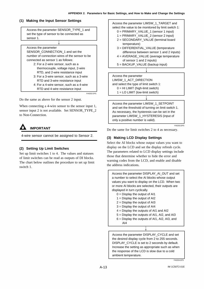
IM 1C50T2-01EA-13
APPENDIX 2. Parameters for Basic Settings, and How to Make and Change the Settings
(1) Making the Input Sensor Settings
FA0202.EPS
Access the parameter SENSOR_CONNECTION_1 and set the number of connection wires of the sensor to be connected as sensor 1 as follows:
2: For a 2-wire sensor, such as a thermocouple, voltage input, 2-wire RTD, and 2-wire resistance input
3: For a 3-wire sensor, such as a 3-wire RTD and 3-wire resistance input
4: For a 4-wire sensor, such as a 4-wire RTD and 4-wire resistance input
Access the parameter SENSOR_TYPE_1 and set the type of sensor to be connected as sensor 1.
Do the same as above for the sensor 2 input.
When connecting a 4-wire sensor to the sensor input 1,sensor input 2 is not available. Set SENSOR_TYPE_2to Non-Connection.
IMPORTANT
4-wire sensor cannot be assigned to Sensor 2.
(2) Setting Up Limit SwitchesSet up limit switches 1 to 4. The values and statusesof limit switches can be read as outputs of DI blocks.The chart below outlines the procedure to set up limitswitch 1.
FA0203.EPS
Access the parameter LIMSW_1_TARGET and select the value to be monitored by limit switch 1:
0 = PRIMARY_VALUE_1 (sensor 1 input) 1 = PRIMARY_VALUE_2 (sensor 2 input) 2 = SECONDARY_VALUE (terminal board
temperature) 3 = DIFFERENTIAL_VALUE (temperature
difference between sensor 1 and 2 inputs) 4 = AVERAGE_VALUE (average temperature
of sensor 1 and 2 inputs) 5 = BACKUP_VALUE (backup input)
Access the parameter LIMSW_1_ACT_DIRECTION and select the type of limit switch 1:
0 = HI LIMIT (high-limit switch) 1 = LO LIMIT (low-limit switch)
Access the parameter LIMSW_1_SETPOINT and set the threshold of turning on limit switch 1. As necessary, the hysteresis can be set in the parameter LIMSW_1_HYSTERESIS (input of only a positive number is valid).
Do the same for limit switches 2 to 4 as necessary.
(3) Making LCD Display SettingsSelect the AI blocks whose output values you want todisplay on the LCD and set the display refresh cycle.The parameters related to LCD display settings includethose that determine whether to hide the error andwarning codes from the LCD, and enable and disablethe address indications.
Access the parameter DISPLAY_AI_OUT and set a number to select the AI blocks whose output values you want to display on the LCD. When two or more AI blocks are selected, their outputs are displayed in turn cyclically.
0 = Display the output of AI1 1 = Display the output of AI2 2 = Display the output of AI3 3 = Display the output of AI4 4 = Display the outputs of AI1 and AI2 5 = Display the outputs of AI1, AI2, and AI3 6 = Display the outputs of AI1, AI2, AI3, and
AI4
FA0204.EPS
Access the parameter DISPLAY_CYCLE and set the desired display cycle from 2 to 255 seconds. DISPLAY_CYCLE is set to 2 seconds by default. Increase the setting as appropriate such as when the response of the LCD is slow due to a cold ambient temperature.

IM 1C50T2-01EA-14
APPENDIX 2. Parameters for Basic Settings, and How to Make and Change the Settings
(4) Carrying Out Input CalibrationSince the YTA320 is calibrated at the factory beforeshipment, calibration need not be performed afterdelivery; however, the user can carry out a calibrationby applying arbitrary input levels as appropriate. For athermocouple input, cold junction compensation isperformed for the input level. To carry out a precisecalibration, follow the procedure below to switch offthe CJC prior to calibration. After the calibration, besure to switch back on the CJC. This CJC switchingprocedure is not necessary for inputs other than athermocouple.
FA0205.EPS
Access the parameter CJC_SELECT_1 and set 1. 0 = Cold junction compensation based on the
terminal board temperature 1 = Cold junction compensation based on a
constant
Access the parameter CONSTANT_CJC_TEMP_1 and set 0 (disable CJC).
This disables CJC for the sensor 1 input. Aftercalibration, return the CJC_SELECT_1 setting to 0.The following outlines the calibration procedure for thesensor 1 input. Do the same for the sensor 2 input.
FA0206-1.EPS
Access the parameter CAL_POINT_HI_1, and write the voltage or resistance value that is currently applied.
Vary the input voltage or resistance to a high level appropriate for the sensor type.
Access the parameter CAL_POINT_LO_1, and write the voltage or resistance value that is currently applied.
Check that the sensor type and number of connection wires are set correctly for the sensor 1 input. Refer to Table 5.16 in Section 5.6.4, “Parameters of Transducer Block,” and apply the low level voltage or resistance appropriate for the sensor type, to the input terminals for the sensor 1 input.
Access the parameter CAL_STATE_1 and set 2. 0 = User Cal Off (Invalidate user-set calibration
values) 1 = User Cal On (Validate user-set calibration
values) 2 = Calibration Exec (User calibration mode)
FA0206-2.EPS
Access the parameter CAL_STATE_1 and return the setting to 1 (validate the user-set calibration values).
IMPORTANT
While adjusting one input, connect the correctsensor to the other input. If you do not connecta sensor to the other input, set ‘No Connection’to the sensor type.
(5) Setting Up the Sensor Matching FunctionThe sensor matching function is applicable to Pt100,Pt200, and Pt500 sensors only. The YTA320 employsthe temperature-to-resistance characteristics of RTDsstipulated by IEC Publication 751-1995, which permitsranges of variations for each sensor type, causingmeasurement errors. The sensor matching functionallows you to program each sensor’s inherent constantscalled Callendar-Van Dusen constants, in thetransmitter, and reduces those errors to improve thetemperature measurement accuracy.
The resistance value of an RTD and the temperature thave the following relation:
Rt = R01 + (1 + 0.01)t – • /104t 2
– • /108(t – 100)t 3 (Eq. 1)
where
Rt = resistance (Ω) at temperature t (°C)
R0 = inherent constant of the sensor=resistance (Ω) at 0°C
= inherent constant of the sensor
= inherent constant of the sensor
= inherent constant of the sensor
(= 0 if t > 0°C)
The precise values of R0, , , and can be obtainedby measuring the characteristics of each RTD atseveral temperatures. This relation is also expressedby a different equation using inherent constants R0, A,B, and C as shown below.
Rt = R0 1 + A• t + B • t 2 + C(t – 100)t 3
(Eq. 2)
where
Rt = resistance (Ω) at temperature t (°C)
R0 = inherent constant of the sensor= resistance (Ω) at 0°C
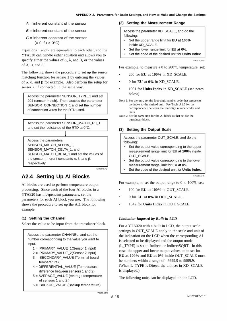
IM 1C50T2-01EA-15
APPENDIX 2. Parameters for Basic Settings, and How to Make and Change the Settings
A = inherent constant of the sensor
B = inherent constant of the sensor
C = inherent constant of the sensor(= 0 if t > 0°C)
Equations 1 and 2 are equivalent to each other, and theYTA320 can handle either equation and allows you tospecify either the values of , , and , or the valuesof A, B, and C.
The following shows the procedure to set up the sensormatching function for sensor 1 by entering the valuesof , , and for example. Also perform the setup forsensor 2, if connected, in the same way.
FA0207.EPS
Access the parameter SENSOR_MATCH_R0_1 and set the resistance of the RTD at 0°C.
Access the parameter SENSOR_TYPE_1 and set 204 (sensor match). Then, access the parameter SENSOR_CONNECTION_1 and set the number of connection wires for the RTD used.
Access the parameters SENSOR_MATCH_ALPHA_1, SENSOR_MATCH_DELTA_1, and SENSOR_MATCH_BETA_1 and set the values of the sensor-inherent constants , , and , respectively.
A2.4 Setting Up AI BlocksAI blocks are used to perform temperature outputprocessing. Since each of the four AI blocks in aYTA320 has independent parameters, set theparameters for each AI block you use. The followingshows the procedure to set up the AI1 block forexample.
(1) Setting the ChannelSelect the value to be input from the transducer block.
FA0208.EPS
Access the parameter CHANNEL, and set the number corresponding to the value you want to input.
1 = PRIMARY_VALUE_1(Sensor 1 input) 2 = PRIMARY_VALUE_2(Sensor 2 input) 3 = SECONDARY_VALUE (Terminal board
temperature) 4 = DIFFERENTIAL_VALUE (Temperature
difference between sensors 1 and 2) 5 = AVERAGE_VALUE (Average temperature
of sensors 1 and 2 ) 6 = BACKUP_VALUE (Backup temperature)
(2) Setting the Measurement Range
FA0209.EPS
Access the parameter XD_SCALE, and do the following: • Set the upper range limit for EU at 100%
inside XD_SCALE. • Set the lower range limit for EU at 0%.• Set the code of the desired unit for Units Index.
For example, to measure a 0 to 200°C temperature, set:
• 200 for EU at 100% in XD_SCALE.
• 0 for EU at 0% in XD_SCALE.
• 1001 for Units Index in XD_SCALE (see notesbelow).
Note 1: For the unit, set the four-digit number code that representsthe index to the desired unit. See Table A1.5 for thecorrespondence between the four-digit number codes andunits.
Note 2: Set the same unit for the AI block as that set for thetransducer block.
(3) Setting the Output Scale
FA0210.EPS
Access the parameter OUT_SCALE, and do the following: • Set the output value corresponding to the upper
measurement range limit for EU at 100% inside OUT_SCALE.
• Set the output value corresponding to the lower measurement range limit for EU at 0%.
• Set the code of the desired unit for Units Index.
For example, to set the output range to 0 to 100%, set:
• 100 for EU at 100% in OUT_SCALE.
• 0 for EU at 0% in OUT_SCALE.
• 1342 for Units Index in OUT_SCALE.
Limitation Imposed by Built-in LCD
For a YTA320 with a built-in LCD, the output scalesettings in OUT_SCALE apply to the scale and unit ofthe indication on the LCD when the corresponding AIis selected to be displayed and the output mode(L_TYPE) is set to Indirect or IndirectSQRT. In thiscase, the upper and lower output values to be set forEU at 100% and EU at 0% inside OUT_SCALE mustbe numbers within a range of –9999.9 to 9999.9.(When L_TYPE is Direct, the unit set in XD_SCALEis displayed.)
The following units can be displayed on the LCD.
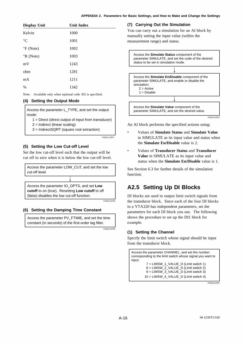
IM 1C50T2-01EA-16
APPENDIX 2. Parameters for Basic Settings, and How to Make and Change the Settings
Display Unit Unit Index
Kelvin 1000
°C 1001
°F (Note) 1002
°R (Note) 1003
mV 1243
ohm 1281
mA 1211
% 1342
Note: Available only when optional code /D2 is specified.
(4) Setting the Output Mode
FA0211.EPS
Access the parameter L_TYPE, and set the output mode:
1 = Direct (direct output of input from transducer) 2 = Indirect (linear scaling) 3 = IndirectSQRT (square root extraction)
(5) Setting the Low Cut-off LevelSet the low cut-off level such that the output will becut off to zero when it is below the low cut-off level.
FA0212.EPS
Access the parameter LOW_CUT, and set the low cut-off level.
Access the parameter IO_OPTS, and set Low cutoff to on (true). Resetting Low cutoff to off (false) disables the low cut-off function.
(6) Setting the Damping Time Constant
FA0213.EPS
Access the parameter PV_FTIME, and set the time constant (in seconds) of the first-order lag filter.
(7) Carrying Out the SimulationYou can carry out a simulation for an AI block bymanually setting the input value (within themeasurement range) and status.
FA0214.EPS
Access the Simulate En/Disable component of the parameter SIMULATE, and enable or disable the simulation:
2 = Active 1 = Disable
Access the Simulate Status component of the parameter SIMULATE, and set the code of the desired status to be set in simulation mode.
Access the Simulate Value component of the parameter SIMULATE, and set the desired value.
An AI block performs the specified actions using:
• Values of Simulate Status and Simulate Valuein SIMULATE as its input value and status whenthe Simulate En/Disable value is 2.
• Values of Transducer Status and TransducerValue in SIMULATE as its input value andstatus when the Simulate En/Disable value is 1.
See Section 6.3 for further details of the simulationfunction.
A2.5 Setting Up DI BlocksDI blocks are used to output limit switch signals fromthe transducer block. Since each of the four DI blocksin a YTA320 has independent parameters, set theparameters for each DI block you use. The followingshows the procedure to set up the DI1 block forexample.
(1) Setting the ChannelSpecify the limit switch whose signal should be inputfrom the transducer block.
FA0215.EPS
Access the parameter CHANNEL, and set the number corresponding to the limit switch whose signal you want to input:
7 = LIMSW_1_VALUE_D (Limit switch 1)8 = LIMSW_2_VALUE_D (Limit switch 2)9 = LIMSW_3_VALUE_D (Limit switch 3)
10 = LIMSW_4_VALUE_D (Limit switch 4)
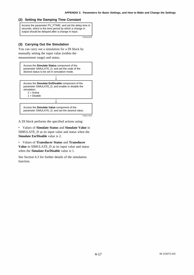
IM 1C50T2-01EA-17
APPENDIX 2. Parameters for Basic Settings, and How to Make and Change the Settings
(2) Setting the Damping Time Constant
FA0216.EPS
Access the parameter PV_FTIME, and set the delay time in seconds, which is the time period by which a change in output should be delayed after a change in input.
(3) Carrying Out the SimulationYou can carry out a simulation for a DI block bymanually setting the input value (within themeasurement range) and status.
FA0217.EPS
Access the Simulate En/Disable component of the parameter SIMULATE_D, and enable or disable the simulation:
2 = Active 1 = Disable
Access the Simulate Status component of the parameter SIMULATE_D, and set the code of the desired status to be set in simulation mode.
Access the Simulate Value component of the parameter SIMULATE_D, and set the desired value.
A DI block performs the specified actions using:
• Values of Simulate Status and Simulate Value inSIMULATE_D as its input value and status when theSimulate En/Disable value is 2.
• Values of Transducer Status and TransducerValue in SIMULATE_D as its input value and statuswhen the Simulate En/Disable value is 1.
See Section 6.3 for further details of the simulationfunction.
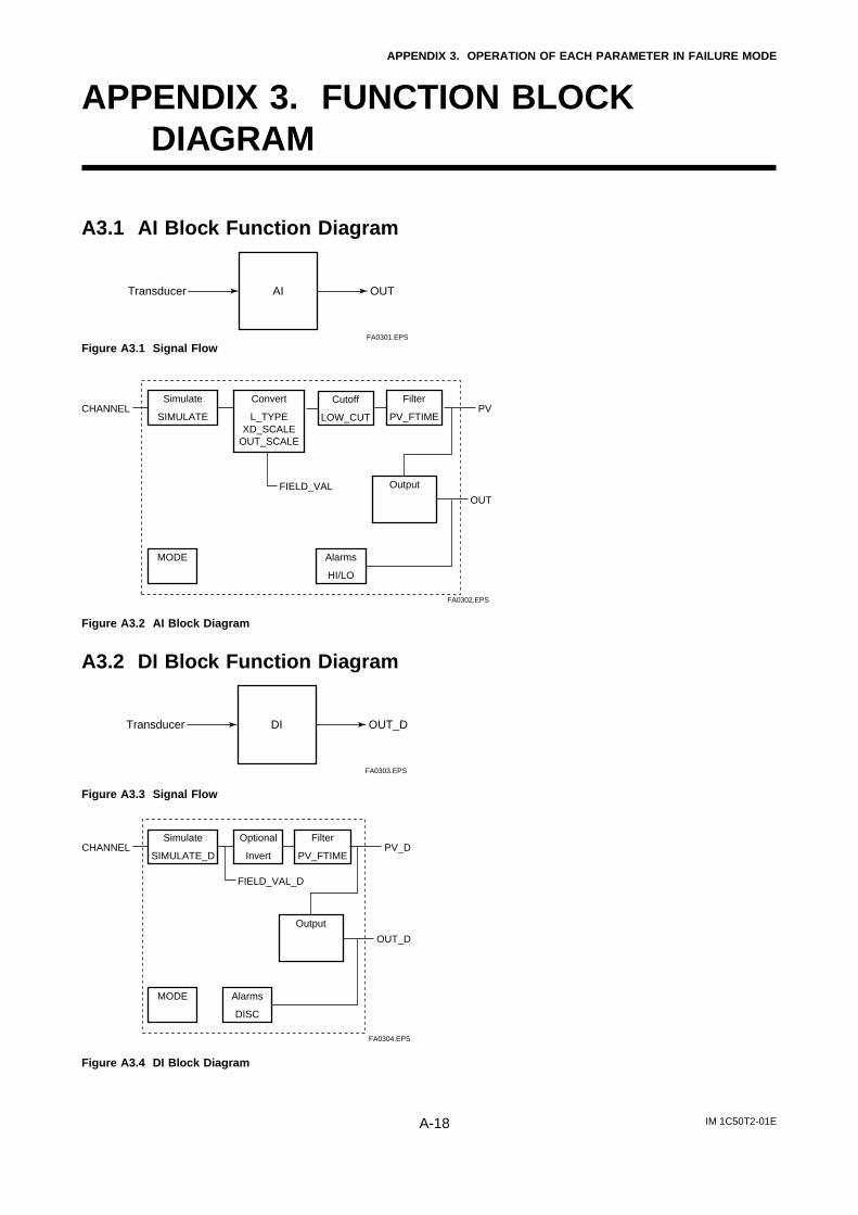
IM 1C50T2-01EA-18
APPENDIX 3. OPERATION OF EACH PARAMETER IN FAILURE MODE
APPENDIX 3. FUNCTION BLOCKDIAGRAM
A3.1 AI Block Function Diagram
FA0301.EPS
AITransducer OUT
Figure A3.1 Signal Flow
FA0302.EPS
Cutoff LOW_CUT
Output
OUTFIELD_VAL
Simulate
SIMULATE
Convert
L_TYPEXD_SCALE
OUT_SCALE
Alarms
HI/LO
MODE
Filter
PV_FTIMECHANNEL PV
Figure A3.2 AI Block Diagram
A3.2 DI Block Function Diagram
FA0303.EPS
DITransducer OUT_D
Figure A3.3 Signal Flow
FA0304.EPS
Output
OUT_D
FIELD_VAL_D
Simulate
SIMULATE_D
Optional
Invert
Alarms
DISC
MODE
Filter
PV_FTIMECHANNEL PV_D
Figure A3.4 DI Block Diagram
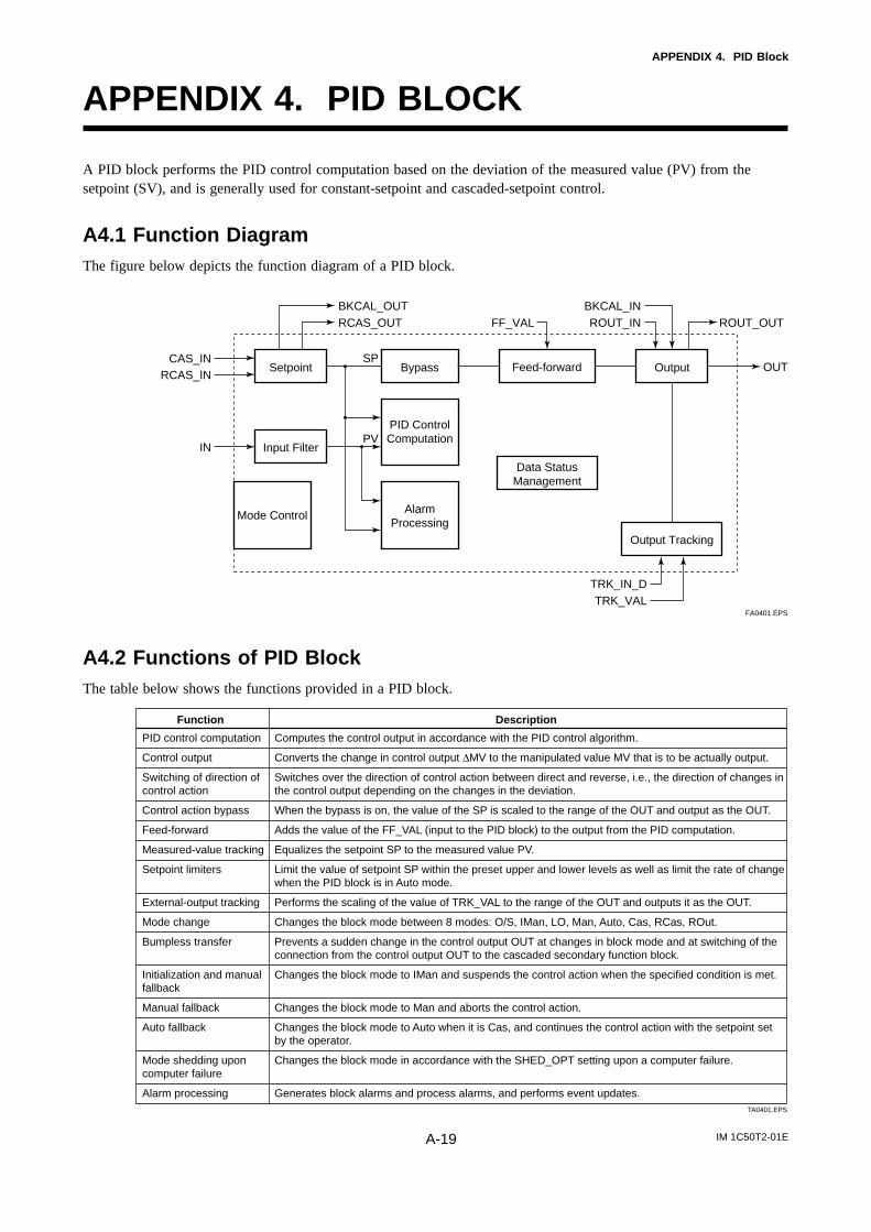
IM 1C50T2-01EA-19
APPENDIX 4. PID Block
APPENDIX 4. PID BLOCK
A PID block performs the PID control computation based on the deviation of the measured value (PV) from thesetpoint (SV), and is generally used for constant-setpoint and cascaded-setpoint control.
A4.1 Function DiagramThe figure below depicts the function diagram of a PID block.
Setpoint OutputBypass
Input Filter
PID Control Computation
Alarm Processing
Mode Control
Feed-forward
Data Status Management
Output Tracking
CAS_IN
BKCAL_OUTRCAS_OUT
BKCAL_INROUT_IN ROUT_OUTFF_VAL
RCAS_IN
TRK_IN_DTRK_VAL
IN
OUT
PV
SP
FA0401.EPS
A4.2 Functions of PID BlockThe table below shows the functions provided in a PID block.
PID control computation
Control output
Switching of direction of control action
Control action bypass
Feed-forward
Measured-value tracking
Setpoint limiters
External-output tracking
Mode change
Bumpless transfer
Initialization and manual fallback
Manual fallback
Auto fallback
Mode shedding upon computer failure
Alarm processing
Function Description
Computes the control output in accordance with the PID control algorithm.
Converts the change in control output ∆MV to the manipulated value MV that is to be actually output.
Switches over the direction of control action between direct and reverse, i.e., the direction of changes in the control output depending on the changes in the deviation.
When the bypass is on, the value of the SP is scaled to the range of the OUT and output as the OUT.
Adds the value of the FF_VAL (input to the PID block) to the output from the PID computation.
Equalizes the setpoint SP to the measured value PV.
Limit the value of setpoint SP within the preset upper and lower levels as well as limit the rate of change when the PID block is in Auto mode.
Performs the scaling of the value of TRK_VAL to the range of the OUT and outputs it as the OUT.
Changes the block mode between 8 modes: O/S, IMan, LO, Man, Auto, Cas, RCas, ROut.
Prevents a sudden change in the control output OUT at changes in block mode and at switching of the connection from the control output OUT to the cascaded secondary function block.
Changes the block mode to IMan and suspends the control action when the specified condition is met.
Changes the block mode to Man and aborts the control action.
Changes the block mode to Auto when it is Cas, and continues the control action with the setpoint set by the operator.
Changes the block mode in accordance with the SHED_OPT setting upon a computer failure.
Generates block alarms and process alarms, and performs event updates. TA0401.EPS
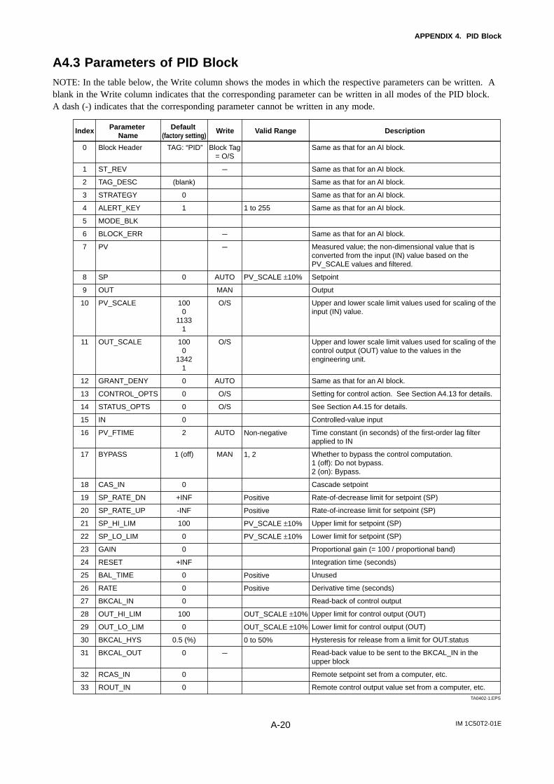
IM 1C50T2-01EA-20
APPENDIX 4. PID Block
A4.3 Parameters of PID BlockNOTE: In the table below, the Write column shows the modes in which the respective parameters can be written. Ablank in the Write column indicates that the corresponding parameter can be written in all modes of the PID block.A dash (-) indicates that the corresponding parameter cannot be written in any mode.
0
1
2
3
4
5
6
7
8
9
10
11
12
13
14
15
16
17
18
19
20
21
22
23
24
25
26
27
28
29
30
31
32
33
Index Default (factory setting)
Parameter Name
Valid RangeWrite Description
Block Header
ST_REV
TAG_DESC
STRATEGY
ALERT_KEY
MODE_BLK
BLOCK_ERR
PV
SP
OUT
PV_SCALE
OUT_SCALE
GRANT_DENY
CONTROL_OPTS
STATUS_OPTS
IN
PV_FTIME
BYPASS
CAS_IN
SP_RATE_DN
SP_RATE_UP
SP_HI_LIM
SP_LO_LIM
GAIN
RESET
BAL_TIME
RATE
BKCAL_IN
OUT_HI_LIM
OUT_LO_LIM
BKCAL_HYS
BKCAL_OUT
RCAS_IN
ROUT_IN
TAG: “PID”
(blank)
0
1
0
1000
11331
1000
13421
0
0
0
0
2
1 (off)
0
+INF
-INF
100
0
0
+INF
0
0
0
100
0
0.5 (%)
0
0
0
Block Tag= O/S
---
---
---
AUTO
MAN
O/S
O/S
AUTO
O/S
O/S
AUTO
MAN
---
Same as that for an AI block.
Same as that for an AI block.
Same as that for an AI block.
Same as that for an AI block.
Same as that for an AI block.
Same as that for an AI block.
Measured value; the non-dimensional value that is converted from the input (IN) value based on the PV_SCALE values and filtered.
Setpoint
Output
Upper and lower scale limit values used for scaling of the input (IN) value.
Upper and lower scale limit values used for scaling of the control output (OUT) value to the values in the engineering unit.
Same as that for an AI block.
Setting for control action. See Section A4.13 for details.
See Section A4.15 for details.
Controlled-value input
Time constant (in seconds) of the first-order lag filter applied to IN
Whether to bypass the control computation. 1 (off): Do not bypass.2 (on): Bypass.
Cascade setpoint
Rate-of-decrease limit for setpoint (SP)
Rate-of-increase limit for setpoint (SP)
Upper limit for setpoint (SP)
Lower limit for setpoint (SP)
Proportional gain (= 100 / proportional band)
Integration time (seconds)
Unused
Derivative time (seconds)
Read-back of control output
Upper limit for control output (OUT)
Lower limit for control output (OUT)
Hysteresis for release from a limit for OUT.status
Read-back value to be sent to the BKCAL_IN in the upper block
Remote setpoint set from a computer, etc.
Remote control output value set from a computer, etc.
1 to 255
PV_SCALE ±10%
Non-negative
1, 2
Positive
Positive
PV_SCALE ±10%
PV_SCALE ±10%
Positive
Positive
OUT_SCALE ±10%
OUT_SCALE ±10%
0 to 50%
TA0402-1.EPS
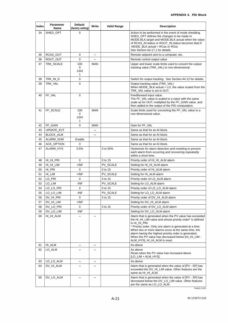
IM 1C50T2-01EA-21
APPENDIX 4. PID Block
34
35
36
37
38
39
40
41
42
43
44
45
46
47
48
49
50
51
52
53
54
55
56
57
58
59
60
61
62
63
64
65
Index Default (factory setting)
Parameter Name
Valid RangeWrite Description
SHED_OPT
RCAS_OUT
ROUT_OUT
TRK_SCALE
TRK_IN_D
TRK_VAL
FF_VAL
FF_SCALE
FF_GAIN
UPDATE_EVT
BLOCK_ALM
ALARM_SUM
ACK_OPTION
ALARM_HYS
HI_HI_PRI
HI_HI_LIM
HI_PRI
HI_LIM
LO_PRI
LO_LIM
LO_LO_PRI
LO_LO_LIM
DV_HI_PRI
DV_HI_LIM
DV_LO_PRI
DV_LO_LIM
HI_HI_ALM
HI_ALM
LO_ALM
LO_LO_ALM
DV_HI_ALM
DV_LO_ALM
0
0
0
1000
13421
0
0
0
1000
13421
0
Enable
0
0.5%
0
+INF
0
+INF
0
-INF
0
-INF
0
+INF
0
-INF
---
---
---
---
---
---
---
---
MAN
MAN
MAN
---
---
---
---
---
---
---
---
Action to be performed in the event of mode shedding.SHED_OPT defines the changes to be made to MODE.BLK.target and MODE.BLK.actual when the value of RCAS_IN.status or ROUT_IN.status becomes Bad if .MODE_BLK.actual = RCas or ROut. See Section A4.17.1 for details.
Remote setpoint sent to a computer, etc.
Remote control output value
Upper and lower scale limits used to convert the output tracking value (TRK_VAL) to non-dimensional.
Switch for output tracking. See Section A4.12 for details.
Output tracking value (TRK_VAL)When MODE_BLK.actual = LO, the value scaled from the TRK_VAL value is set in OUT.
Feedforward input value. The FF_VAL value is scaled to a value with the same scale as for OUT, multiplied by the FF_GAIN value, and then added to the output of the PID computation.
Scale limits used for converting the FF_VAL value to a non-dimensional value.
Gain for FF_VAL
Same as that for an AI block.
Same as that for an AI block.
Same as that for an AI block.
Same as that for an AI block.
Hysteresis for alarm detection and resetting to prevent each alarm from occurring and recovering repeatedly within a short time.
Priority order of HI_HI_ALM alarm
Setting for HI_HI_ALM alarm
Priority order of HI_ALM alarm
Setting for HI_ALM alarm
Priority order of LO_ALM alarm
Setting for LO_ALM alarm
Priority order of LO_LO_ALM alarm
Setting for LO_LO_ALM alarm
Priority order of DV_HI_ALM alarm
Setting for DV_HI_ALM alarm
Priority order of DV_LO_ALM alarm
Setting for DV_LO_ALM alarm
Alarm that is generated when the PV value has exceeded the HI_HI_LIM value and whose priority order* is defined in HI_HI_PRI. * Priority order: Only one alarm is generated at a time. When two or more alarms occur at the same time, the alarm having the highest priority order is generated. When the PV value has decreased below [HI_HI_LIM - ALM_HYS], HI_HI_ALM is reset.
As above
As aboveReset when the PV value has increased above [LO_LIM + ALM_HYS].
As above
Alarm that is generated when the value of [PV - SP] has exceeded the DV_HI_LIM value. Other features are the same as HI_HI_ALM.
Alarm that is generated when the value of [PV - SP] has decreased below the DV_LO_LIM value. Other features are the same as LO_LO_ALM.
0 to 50%
0 to 15
PV_SCALE
0 to 15
PV_SCALE
0 to 15
PV_SCALE
0 to 15
PV_SCALE
0 to 15
0 to 15
TA0402-2.EPS
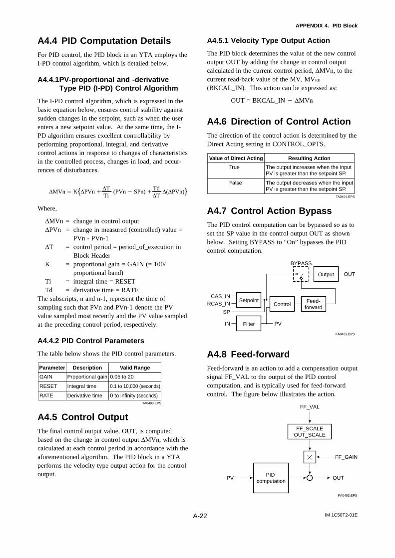
IM 1C50T2-01EA-22
APPENDIX 4. PID Block
A4.4 PID Computation DetailsFor PID control, the PID block in an YTA employs theI-PD control algorithm, which is detailed below.
A4.4.1PV-proportional and -derivativeType PID (I-PD) Control Algorithm
The I-PD control algorithm, which is expressed in thebasic equation below, ensures control stability againstsudden changes in the setpoint, such as when the userenters a new setpoint value. At the same time, the I-PD algorithm ensures excellent controllability byperforming proportional, integral, and derivativecontrol actions in response to changes of characteristicsin the controlled process, changes in load, and occur-rences of disturbances.
∆MVn K ∆PVn (PVn SPn) ∆(∆PVn)∆TTi
Td∆T
Where,
∆MVn = change in control output∆PVn = change in measured (controlled) value =
PVn - PVn-1∆T = control period = period_of_execution in
Block HeaderK = proportional gain = GAIN (= 100/
proportional band)Ti = integral time = RESETTd = derivative time = RATE
The subscripts, n and n-1, represent the time ofsampling such that PVn and PVn-1 denote the PVvalue sampled most recently and the PV value sampledat the preceding control period, respectively.
A4.4.2 PID Control Parameters
The table below shows the PID control parameters.
Parameter Description Valid Range
GAIN
RESET
RATE
Proportional gain
Integral time
Derivative time
0.05 to 20
0.1 to 10,000 (seconds)
0 to infinity (seconds)TA0403.EPS
A4.5 Control OutputThe final control output value, OUT, is computedbased on the change in control output ∆MVn, which iscalculated at each control period in accordance with theaforementioned algorithm. The PID block in a YTAperforms the velocity type output action for the controloutput.
A4.5.1 Velocity Type Output Action
The PID block determines the value of the new controloutput OUT by adding the change in control outputcalculated in the current control period, ∆MVn, to thecurrent read-back value of the MV, MVRB
(BKCAL_IN). This action can be expressed as:
OUT = BKCAL_IN ∆MVn
A4.6 Direction of Control ActionThe direction of the control action is determined by theDirect Acting setting in CONTROL_OPTS.
Value of Direct Acting Resulting Action
The output increases when the input PV is greater than the setpoint SP.
The output decreases when the input PV is greater than the setpoint SP.
True
False
TA0404.EPS
A4.7 Control Action BypassThe PID control computation can be bypassed so as toset the SP value in the control output OUT as shownbelow. Setting BYPASS to “On” bypasses the PIDcontrol computation.
SetpointControl
Feed- forward
CAS_IN
FilterIN PV
BYPASS
SP
RCAS_IN
Output OUT
FA0402.EPS
A4.8 Feed-forwardFeed-forward is an action to add a compensation outputsignal FF_VAL to the output of the PID controlcomputation, and is typically used for feed-forwardcontrol. The figure below illustrates the action.
PID computation
FF_SCALEOUT_SCALE
PV OUT
FF_VAL
FF_GAIN
FA0403.EPS
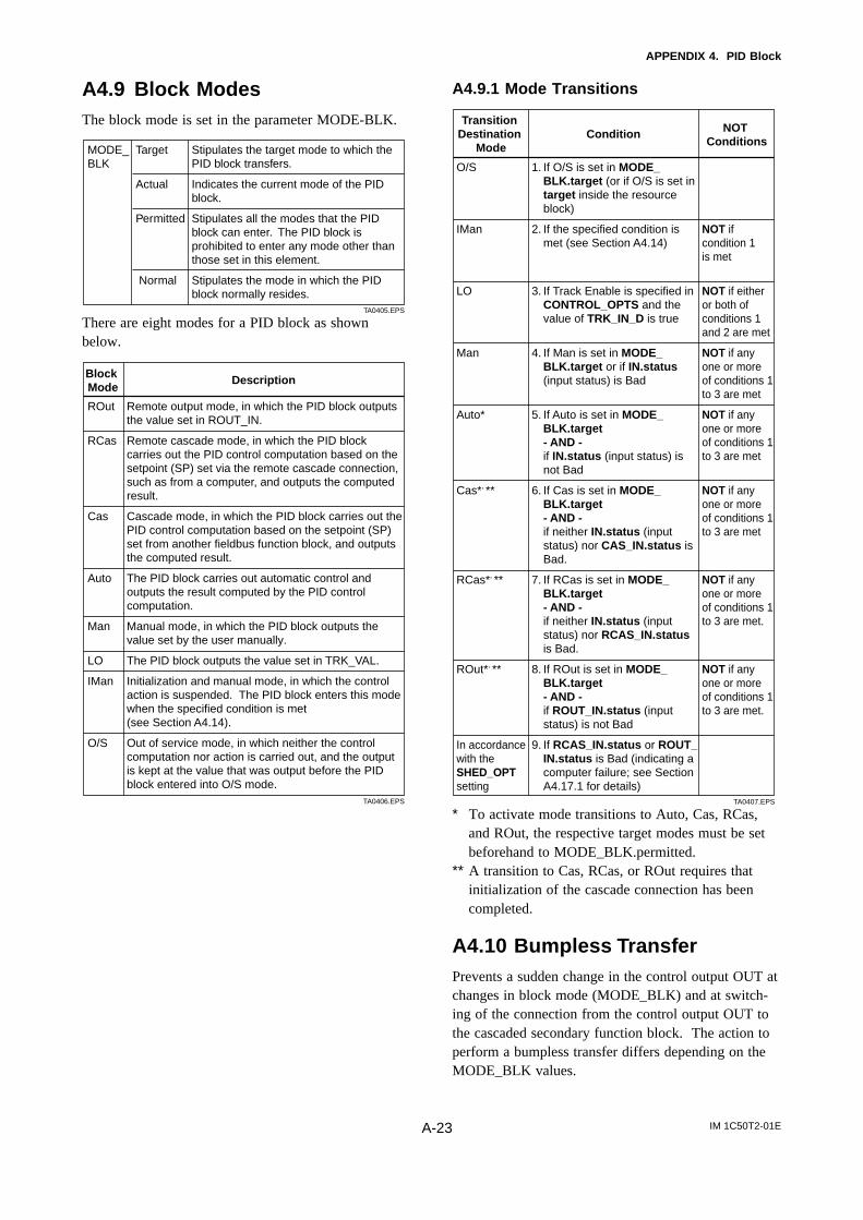
IM 1C50T2-01EA-23
APPENDIX 4. PID Block
A4.9 Block ModesThe block mode is set in the parameter MODE-BLK.
Stipulates the target mode to which the PID block transfers.
Indicates the current mode of the PID block.
Stipulates all the modes that the PID block can enter. The PID block is prohibited to enter any mode other than those set in this element.
Stipulates the mode in which the PID block normally resides.
MODE_BLK
Target
Actual
Permitted
Normal
TA0405.EPS
There are eight modes for a PID block as shownbelow.
Block Mode
Description
Remote output mode, in which the PID block outputs the value set in ROUT_IN.
Remote cascade mode, in which the PID block carries out the PID control computation based on the setpoint (SP) set via the remote cascade connection, such as from a computer, and outputs the computed result.
Cascade mode, in which the PID block carries out the PID control computation based on the setpoint (SP) set from another fieldbus function block, and outputs the computed result.
The PID block carries out automatic control and outputs the result computed by the PID control computation.
Manual mode, in which the PID block outputs the value set by the user manually.
The PID block outputs the value set in TRK_VAL.
Initialization and manual mode, in which the control action is suspended. The PID block enters this mode when the specified condition is met (see Section A4.14).
Out of service mode, in which neither the control computation nor action is carried out, and the output is kept at the value that was output before the PID block entered into O/S mode.
ROut
RCas
Cas
Auto
Man
LO
IMan
O/S
TA0406.EPS
A4.9.1 Mode Transitions
Transition Destination
ModeCondition NOT
Conditions
1. If O/S is set in MODE_BLK.target (or if O/S is set in target inside the resource block)
2. If the specified condition is met (see Section A4.14)
3. If Track Enable is specified in CONTROL_OPTS and the value of TRK_IN_D is true
4. If Man is set in MODE_BLK.target or if IN.status (input status) is Bad
5. If Auto is set in MODE_BLK.target- AND -if IN.status (input status) is not Bad
6. If Cas is set in MODE_BLK.target- AND -if neither IN.status (input status) nor CAS_IN.status is Bad.
7. If RCas is set in MODE_BLK.target- AND -if neither IN.status (input status) nor RCAS_IN.status is Bad.
8. If ROut is set in MODE_BLK.target - AND -if ROUT_IN.status (input status) is not Bad
9. If RCAS_IN.status or ROUT_IN.status is Bad (indicating a computer failure; see Section A4.17.1 for details)
NOT if condition 1 is met
NOT if either or both of conditions 1 and 2 are met
NOT if any one or more of conditions 1 to 3 are met
NOT if any one or more of conditions 1 to 3 are met
NOT if any one or more of conditions 1 to 3 are met
NOT if any one or more of conditions 1 to 3 are met.
NOT if any one or more of conditions 1 to 3 are met.
O/S
IMan
LO
Man
Auto*
Cas*, **
RCas*, **
ROut*, **
In accordance with the SHED_OPT setting
TA0407.EPS
* To activate mode transitions to Auto, Cas, RCas,and ROut, the respective target modes must be setbeforehand to MODE_BLK.permitted.
** A transition to Cas, RCas, or ROut requires thatinitialization of the cascade connection has beencompleted.
A4.10 Bumpless TransferPrevents a sudden change in the control output OUT atchanges in block mode (MODE_BLK) and at switch-ing of the connection from the control output OUT tothe cascaded secondary function block. The action toperform a bumpless transfer differs depending on theMODE_BLK values.
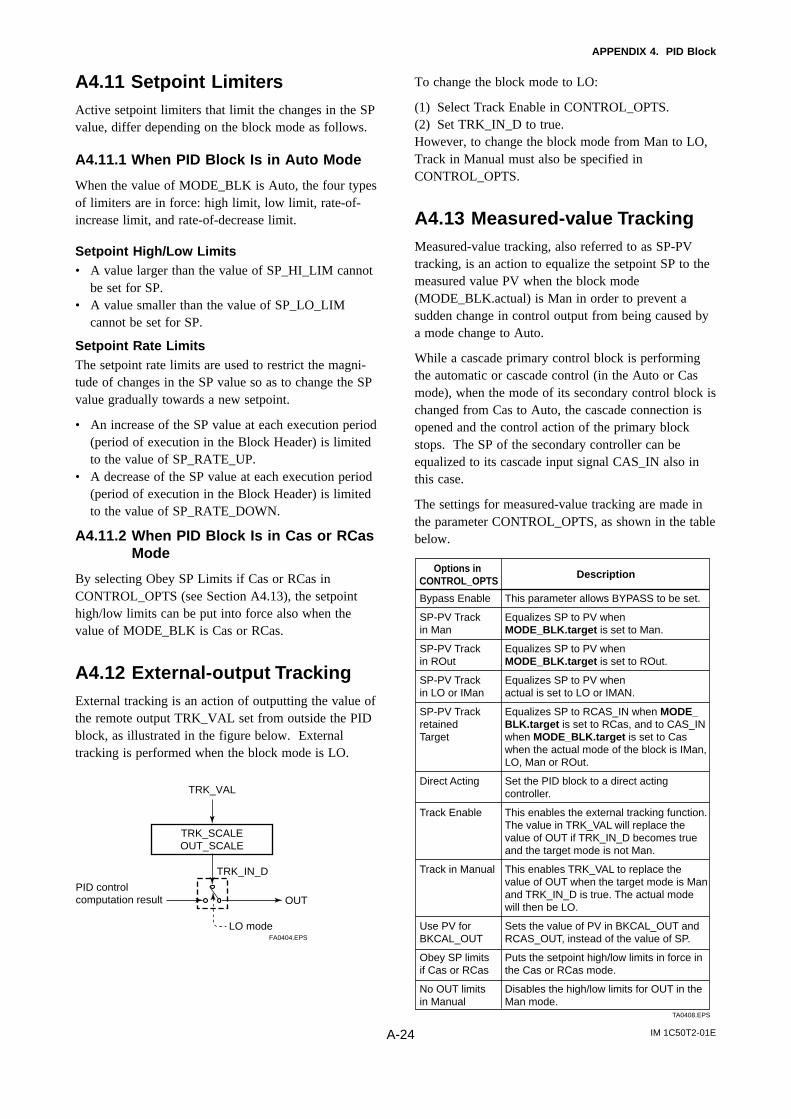
IM 1C50T2-01EA-24
APPENDIX 4. PID Block
A4.11 Setpoint LimitersActive setpoint limiters that limit the changes in the SPvalue, differ depending on the block mode as follows.
A4.11.1 When PID Block Is in Auto Mode
When the value of MODE_BLK is Auto, the four typesof limiters are in force: high limit, low limit, rate-of-increase limit, and rate-of-decrease limit.
Setpoint High/Low Limits• A value larger than the value of SP_HI_LIM cannot
be set for SP.• A value smaller than the value of SP_LO_LIM
cannot be set for SP.
Setpoint Rate LimitsThe setpoint rate limits are used to restrict the magni-tude of changes in the SP value so as to change the SPvalue gradually towards a new setpoint.
• An increase of the SP value at each execution period(period of execution in the Block Header) is limitedto the value of SP_RATE_UP.
• A decrease of the SP value at each execution period(period of execution in the Block Header) is limitedto the value of SP_RATE_DOWN.
A4.11.2 When PID Block Is in Cas or RCasMode
By selecting Obey SP Limits if Cas or RCas inCONTROL_OPTS (see Section A4.13), the setpointhigh/low limits can be put into force also when thevalue of MODE_BLK is Cas or RCas.
A4.12 External-output TrackingExternal tracking is an action of outputting the value ofthe remote output TRK_VAL set from outside the PIDblock, as illustrated in the figure below. Externaltracking is performed when the block mode is LO.
TRK_SCALEOUT_SCALE
TRK_VAL
OUT
TRK_IN_D
LO mode
PID control computation result
FA0404.EPS
To change the block mode to LO:
(1) Select Track Enable in CONTROL_OPTS.(2) Set TRK_IN_D to true.However, to change the block mode from Man to LO,Track in Manual must also be specified inCONTROL_OPTS.
A4.13 Measured-value TrackingMeasured-value tracking, also referred to as SP-PVtracking, is an action to equalize the setpoint SP to themeasured value PV when the block mode(MODE_BLK.actual) is Man in order to prevent asudden change in control output from being caused bya mode change to Auto.
While a cascade primary control block is performingthe automatic or cascade control (in the Auto or Casmode), when the mode of its secondary control block ischanged from Cas to Auto, the cascade connection isopened and the control action of the primary blockstops. The SP of the secondary controller can beequalized to its cascade input signal CAS_IN also inthis case.
The settings for measured-value tracking are made inthe parameter CONTROL_OPTS, as shown in the tablebelow.
Options in CONTROL_OPTS
Description
This parameter allows BYPASS to be set.
Equalizes SP to PV when MODE_BLK.target is set to Man.
Equalizes SP to PV when MODE_BLK.target is set to ROut.
Equalizes SP to PV when actual is set to LO or IMAN.
Equalizes SP to RCAS_IN when MODE_BLK.target is set to RCas, and to CAS_IN when MODE_BLK.target is set to Caswhen the actual mode of the block is IMan, LO, Man or ROut.
Set the PID block to a direct acting controller.
This enables the external tracking function.The value in TRK_VAL will replace the value of OUT if TRK_IN_D becomes true and the target mode is not Man.
This enables TRK_VAL to replace the value of OUT when the target mode is Man and TRK_IN_D is true. The actual mode will then be LO.
Sets the value of PV in BKCAL_OUT and RCAS_OUT, instead of the value of SP.
Puts the setpoint high/low limits in force in the Cas or RCas mode.
Disables the high/low limits for OUT in the Man mode.
Bypass Enable
SP-PV Track in Man
SP-PV Track in ROut
SP-PV Track in LO or IMan
SP-PV Track retained Target
Direct Acting
Track Enable
Track in Manual
Use PV for BKCAL_OUT
Obey SP limits if Cas or RCas
No OUT limits in Manual
TA0408.EPS
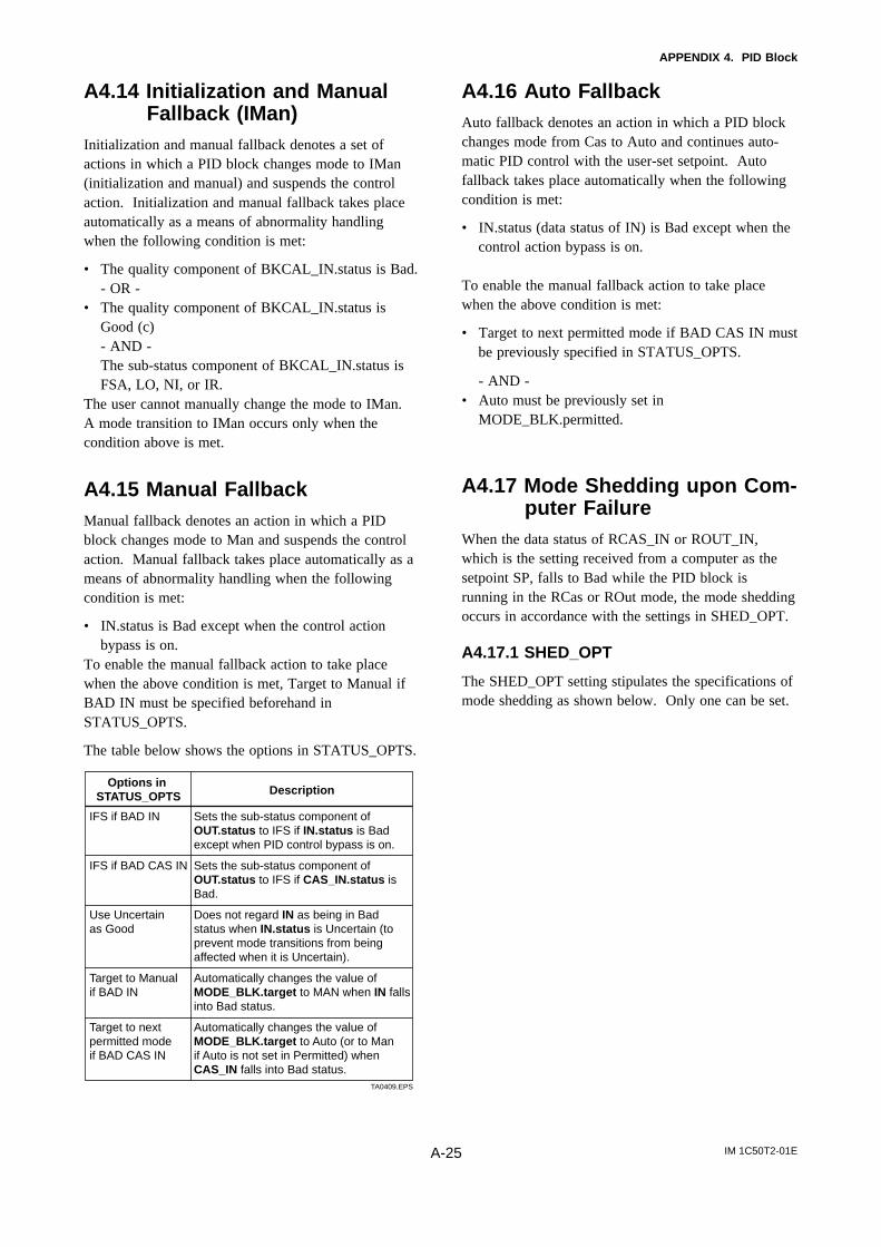
IM 1C50T2-01EA-25
APPENDIX 4. PID Block
A4.14 Initialization and ManualFallback (IMan)
Initialization and manual fallback denotes a set ofactions in which a PID block changes mode to IMan(initialization and manual) and suspends the controlaction. Initialization and manual fallback takes placeautomatically as a means of abnormality handlingwhen the following condition is met:
• The quality component of BKCAL_IN.status is Bad.- OR -
• The quality component of BKCAL_IN.status isGood (c)- AND -The sub-status component of BKCAL_IN.status isFSA, LO, NI, or IR.
The user cannot manually change the mode to IMan.A mode transition to IMan occurs only when thecondition above is met.
A4.15 Manual FallbackManual fallback denotes an action in which a PIDblock changes mode to Man and suspends the controlaction. Manual fallback takes place automatically as ameans of abnormality handling when the followingcondition is met:
• IN.status is Bad except when the control actionbypass is on.
To enable the manual fallback action to take placewhen the above condition is met, Target to Manual ifBAD IN must be specified beforehand inSTATUS_OPTS.
The table below shows the options in STATUS_OPTS.
Options in STATUS_OPTS Description
Sets the sub-status component of OUT.status to IFS if IN.status is Bad except when PID control bypass is on.
Sets the sub-status component of OUT.status to IFS if CAS_IN.status is Bad.
Does not regard IN as being in Bad status when IN.status is Uncertain (to prevent mode transitions from being affected when it is Uncertain).
Automatically changes the value of MODE_BLK.target to MAN when IN falls into Bad status.
Automatically changes the value of MODE_BLK.target to Auto (or to Man if Auto is not set in Permitted) when CAS_IN falls into Bad status.
IFS if BAD IN
IFS if BAD CAS IN
Use Uncertain as Good
Target to Manual if BAD IN
Target to next permitted mode if BAD CAS IN
TA0409.EPS
A4.16 Auto FallbackAuto fallback denotes an action in which a PID blockchanges mode from Cas to Auto and continues auto-matic PID control with the user-set setpoint. Autofallback takes place automatically when the followingcondition is met:
• IN.status (data status of IN) is Bad except when thecontrol action bypass is on.
To enable the manual fallback action to take placewhen the above condition is met:
• Target to next permitted mode if BAD CAS IN mustbe previously specified in STATUS_OPTS.
- AND -• Auto must be previously set in
MODE_BLK.permitted.
A4.17 Mode Shedding upon Com-puter Failure
When the data status of RCAS_IN or ROUT_IN,which is the setting received from a computer as thesetpoint SP, falls to Bad while the PID block isrunning in the RCas or ROut mode, the mode sheddingoccurs in accordance with the settings in SHED_OPT.
A4.17.1 SHED_OPT
The SHED_OPT setting stipulates the specifications ofmode shedding as shown below. Only one can be set.
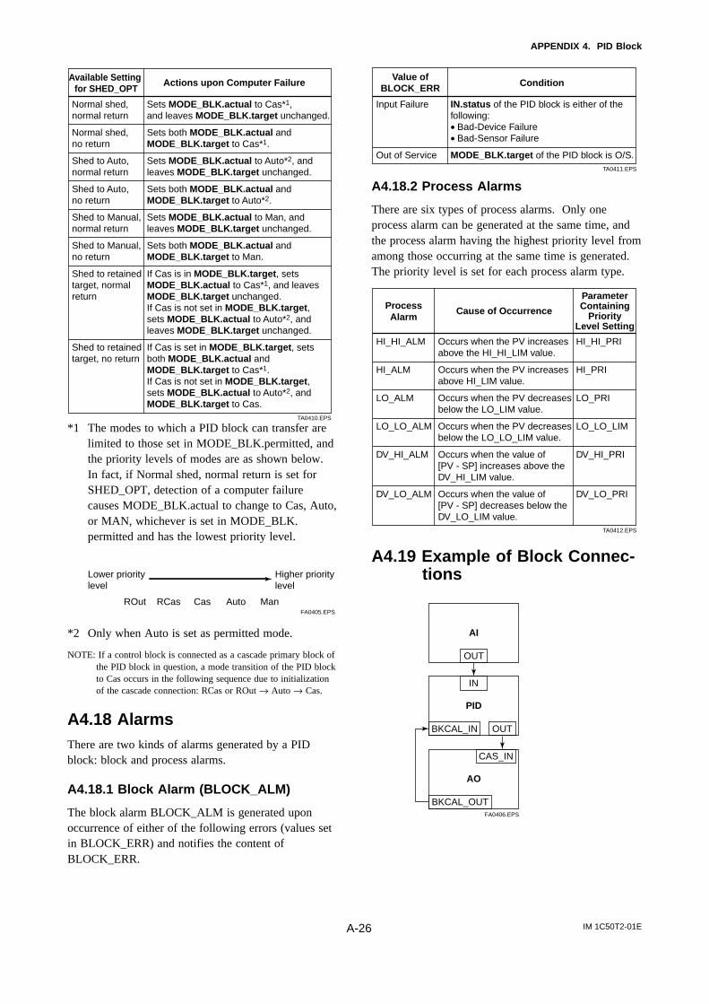
IM 1C50T2-01EA-26
APPENDIX 4. PID Block
Available Setting for SHED_OPT
Actions upon Computer Failure
Sets MODE_BLK.actual to Cas*1, and leaves MODE_BLK.target unchanged.
Sets both MODE_BLK.actual and MODE_BLK.target to Cas*1.
Sets MODE_BLK.actual to Auto*2, and leaves MODE_BLK.target unchanged.
Sets both MODE_BLK.actual and MODE_BLK.target to Auto*2.
Sets MODE_BLK.actual to Man, and leaves MODE_BLK.target unchanged.
Sets both MODE_BLK.actual and MODE_BLK.target to Man.
If Cas is in MODE_BLK.target, sets MODE_BLK.actual to Cas*1, and leaves MODE_BLK.target unchanged.If Cas is not set in MODE_BLK.target, sets MODE_BLK.actual to Auto*2, and leaves MODE_BLK.target unchanged.
If Cas is set in MODE_BLK.target, sets both MODE_BLK.actual and MODE_BLK.target to Cas*1. If Cas is not set in MODE_BLK.target, sets MODE_BLK.actual to Auto*2, and MODE_BLK.target to Cas.
Normal shed, normal return
Normal shed, no return
Shed to Auto, normal return
Shed to Auto, no return
Shed to Manual, normal return
Shed to Manual, no return
Shed to retained target, normal return
Shed to retained target, no return
TA0410.EPS
*1 The modes to which a PID block can transfer arelimited to those set in MODE_BLK.permitted, andthe priority levels of modes are as shown below.In fact, if Normal shed, normal return is set forSHED_OPT, detection of a computer failurecauses MODE_BLK.actual to change to Cas, Auto,or MAN, whichever is set in MODE_BLK.permitted and has the lowest priority level.
FA0405.EPS
Higher priority level
Lower prioritylevel
ROut RCas Cas Auto Man
*2 Only when Auto is set as permitted mode.
NOTE: If a control block is connected as a cascade primary block ofthe PID block in question, a mode transition of the PID blockto Cas occurs in the following sequence due to initializationof the cascade connection: RCas or ROut → Auto → Cas.
A4.18 AlarmsThere are two kinds of alarms generated by a PIDblock: block and process alarms.
A4.18.1 Block Alarm (BLOCK_ALM)
The block alarm BLOCK_ALM is generated uponoccurrence of either of the following errors (values setin BLOCK_ERR) and notifies the content ofBLOCK_ERR.
Value of BLOCK_ERR Condition
IN.status of the PID block is either of the following: • Bad-Device Failure• Bad-Sensor Failure
MODE_BLK.target of the PID block is O/S.
Input Failure
Out of ServiceTA0411.EPS
A4.18.2 Process Alarms
There are six types of process alarms. Only oneprocess alarm can be generated at the same time, andthe process alarm having the highest priority level fromamong those occurring at the same time is generated.The priority level is set for each process alarm type.
Parameter Containing
Priority Level Setting
Cause of OccurrenceProcess Alarm
Occurs when the PV increases above the HI_HI_LIM value.
Occurs when the PV increases above HI_LIM value.
Occurs when the PV decreases below the LO_LIM value.
Occurs when the PV decreases below the LO_LO_LIM value.
Occurs when the value of [PV - SP] increases above the DV_HI_LIM value.
Occurs when the value of [PV - SP] decreases below the DV_LO_LIM value.
HI_HI_PRI
HI_PRI
LO_PRI
LO_LO_LIM
DV_HI_PRI
DV_LO_PRI
HI_HI_ALM
HI_ALM
LO_ALM
LO_LO_ALM
DV_HI_ALM
DV_LO_ALM
TA0412.EPS
A4.19 Example of Block Connec-tions
PID
BKCAL_IN OUT
IN
AO
BKCAL_OUT
CAS_IN
AI
OUT
FA0406.EPS

IM 1C50T2-01EA-27
APPENDIX 4. PID Block
When configuring a simple PID control loop bycombining a YTA transmitter with a fieldbus valvepositioner that contains an AO block, follow theprocedure below to make the settings of the corre-sponding fieldbus function blocks:
1. Connect the AI block and PID block of the YTA,and the AO block of the valve positioner as shownabove.
2. Set MODE_BLK.target of the PID block to O/S,and then set GAIN, RESET, and RATE to appropri-ate values.
3. Check that the value of MODE_BLK.actual of theAI block is Auto.
4. Set MODE_BLK.target of the AO block toCAS|AUTO (meaning "Cas and Auto").
5. Check that the value of BKCAL_IN.status of thePID block is not Bad.
6. Check that the value of IN.status of the PID block isnot Bad.
7. Check that Auto is set in MODE_BLK.permitted ofthe PID block.
8. Set MODE_BLK.target of the PID block to Auto.
When finishing all steps in order, the PID block andAO block exchange the respective information andinitialize the cascade connection. Consequently, thevalue of MODE_BLK.actual of the PID block changesto Auto and automatic PID control starts.
A4.19.1 View Object for PID FunctionBlock
VIEW4
RelativeIndex
Parameter Mnemonic
ST_REV
TAG_DESC
STRATEGY
ALERT_KEY
MODE_BLK
BLOCK_ERR
PV
SP
OUT
PV_SCALE
OUT_SCALE
GRANT_DENY
CONTROL_OPTS
STATUS_OPTS
IN
PV_FTIME
BYPASS
CAS_IN
SP_RATE_DN
SP_RATE_UP
SP_HI_LIM
SP_LO_LIM
GAIN
RESET
BAL_TIME
RATE
BKCAL_IN
OUT_HI_LIM
OUT_LO_LIM
BKCAL_HYS
BKCAL_OUT
RCAS_IN
ROUT_IN
Subtotals
2
2
1
2
2
4
4
4
4
4
4
4
4
41
VIEW3
2
4
2
5
5
5
5
5
5
5
5
5
53
VIEW2
2
11
11
2
1
4
4
4
4
43
VIEW1
2
4
2
5
5
5
5
28
1
2
3
4
5
6
7
8
9
10
11
12
13
14
15
16
17
18
19
20
21
22
23
24
25
26
27
28
29
30
31
32
33
TA0413-1.EPS
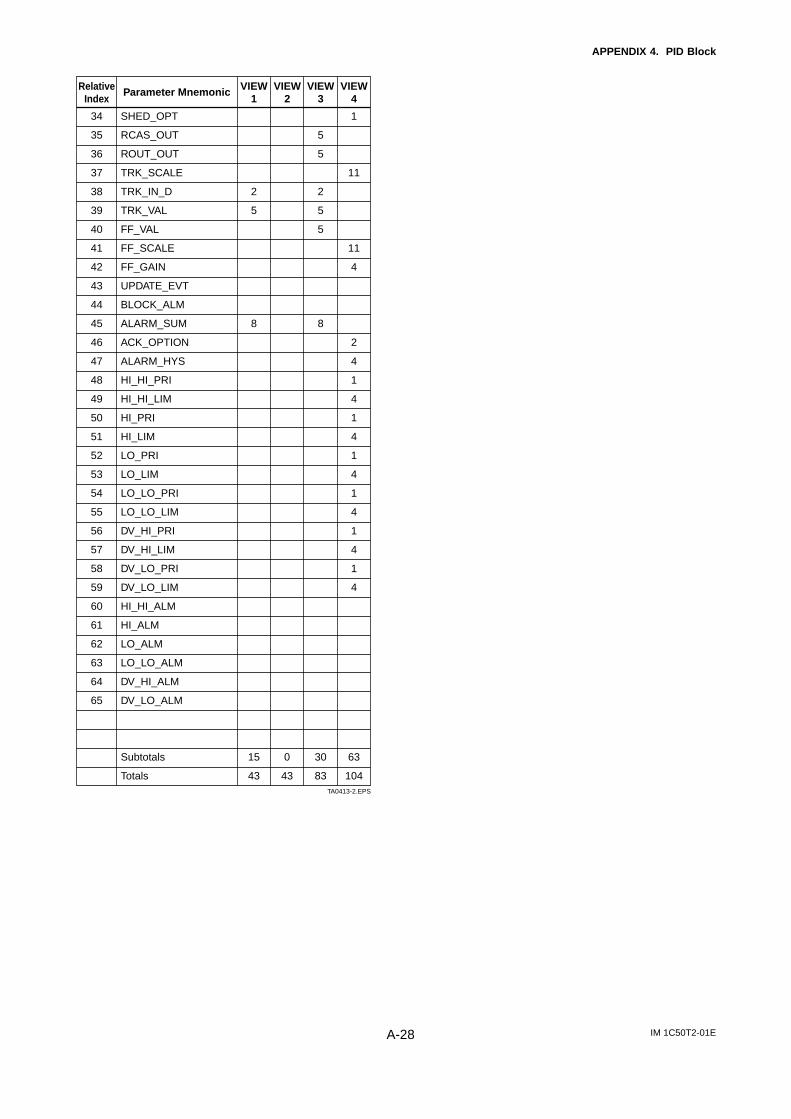
IM 1C50T2-01EA-28
APPENDIX 4. PID Block
VIEW4
RelativeIndex
Parameter Mnemonic
SHED_OPT
RCAS_OUT
ROUT_OUT
TRK_SCALE
TRK_IN_D
TRK_VAL
FF_VAL
FF_SCALE
FF_GAIN
UPDATE_EVT
BLOCK_ALM
ALARM_SUM
ACK_OPTION
ALARM_HYS
HI_HI_PRI
HI_HI_LIM
HI_PRI
HI_LIM
LO_PRI
LO_LIM
LO_LO_PRI
LO_LO_LIM
DV_HI_PRI
DV_HI_LIM
DV_LO_PRI
DV_LO_LIM
HI_HI_ALM
HI_ALM
LO_ALM
LO_LO_ALM
DV_HI_ALM
DV_LO_ALM
Subtotals
Totals
1
11
11
4
2
4
1
4
1
4
1
4
1
4
1
4
1
4
63
104
VIEW3
5
5
2
5
5
8
30
83
VIEW2
VIEW1
2
5
8
15
43
0
43
34
35
36
37
38
39
40
41
42
43
44
45
46
47
48
49
50
51
52
53
54
55
56
57
58
59
60
61
62
63
64
65
TA0413-2.EPS

IM 1C50T2-01EA-29
APPENDIX 5. Link Master Functions
APPENDIX 5. LINK MASTER FUNCTIONS
A5.1 Link Active SchedulerA link active scheduler (LAS) is a deterministic, centralized bus scheduler that can control communications on an H1fieldbus segment. There is only one LAS on an H1 fieldbus segment.
A YTA supports the following LAS functions.
• PN transmission: Identifies a fieldbus device newly connected to the same fieldbus segment. PN is short for ProbeNode.
• PT transmission: Passes a token governing the right to transmit, to a fieldbus device on the same segment. PT isshort for Pass Token.
• CD transmission: Carry out a scheduled transmission to a fieldbus device on the same segment. CD is short forCompel Data.
• Time synchronization: Periodically transmits the time data to all fieldbus devices on the segment and returns thetime data in response to a request from a device.
• Live list equalization: Sends the live list data to link masters on the same segment.• LAS transfer: Transfers the right to be the LAS on the segment to another link master.
A5.2 Link MasterA link master (LM) is any device containing a link active scheduler. There must be at least one LM on a segment.When the LAS on a segment has failed, another LM on the same segment starts working as the LAS.
LMNode address:
0x15SlotTime = 5
LMNode address:
0x16SlotTime = 5
Node address: 0x10SlotTime = 5
Basic deviceNode address:
0xF1
Basic deviceNode address:
0xF2
Basic deviceNode address:
0xF3
Basic deviceNode address:
0xF4
LAS
There are 3 LMs on this segment. LM
FA0501.EPS
Figure 1. Example of Fieldbus configuration-3 LMs on Same Segment
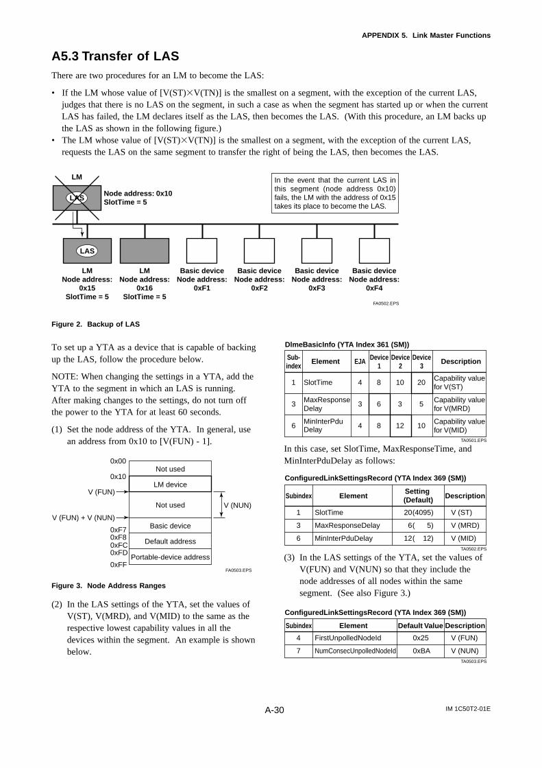
IM 1C50T2-01EA-30
APPENDIX 5. Link Master Functions
A5.3 Transfer of LASThere are two procedures for an LM to become the LAS:
• If the LM whose value of [V(ST)V(TN)] is the smallest on a segment, with the exception of the current LAS,judges that there is no LAS on the segment, in such a case as when the segment has started up or when the currentLAS has failed, the LM declares itself as the LAS, then becomes the LAS. (With this procedure, an LM backs upthe LAS as shown in the following figure.)
• The LM whose value of [V(ST)V(TN)] is the smallest on a segment, with the exception of the current LAS,requests the LAS on the same segment to transfer the right of being the LAS, then becomes the LAS.
LMNode address:
0x15SlotTime = 5
LMNode address:
0x16SlotTime = 5
Node address: 0x10SlotTime = 5
Basic deviceNode address:
0xF1
Basic deviceNode address:
0xF2
Basic deviceNode address:
0xF3
Basic deviceNode address:
0xF4
LAS
LAS
In the event that the current LAS in this segment (node address 0x10) fails, the LM with the address of 0x15 takes its place to become the LAS.
LM
FA0502.EPS
Figure 2. Backup of LAS
To set up a YTA as a device that is capable of backingup the LAS, follow the procedure below.
NOTE: When changing the settings in a YTA, add theYTA to the segment in which an LAS is running.After making changes to the settings, do not turn offthe power to the YTA for at least 60 seconds.
(1) Set the node address of the YTA. In general, usean address from 0x10 to [V(FUN) - 1].
Not used
LM device
Not used
Basic device
Default address
Portable-device address
V (FUN)
V (FUN) + V (NUN)
V (NUN)
0xFF
0xFD0xFC0xF80xF7
0x10
0x00
FA0503.EPS
Figure 3. Node Address Ranges
(2) In the LAS settings of the YTA, set the values ofV(ST), V(MRD), and V(MID) to the same as therespective lowest capability values in all thedevices within the segment. An example is shownbelow.
Sub-index
Element EJA Device1
Device2
Device3
Description
1
3
6
SlotTime MaxResponse Delay
MinInterPdu Delay
4
3
4
8
6
8
10
3
12
20
5
10
Capability value for V(ST)
Capability value for V(MRD)
Capability value for V(MID)
TA0501.EPS
DlmeBasicInfo (YTA Index 361 (SM))
In this case, set SlotTime, MaxResponseTime, andMinInterPduDelay as follows:
Subindex Element
ConfiguredLinkSettingsRecord (YTA Index 369 (SM))
DescriptionSetting (Default)
V (ST)
V (MRD)
V (MID)
20
6
12
(4095)
( 5)
( 12)
SlotTime
MaxResponseDelay
MinInterPduDelay
1
3
6TA0502.EPS
(3) In the LAS settings of the YTA, set the values ofV(FUN) and V(NUN) so that they include thenode addresses of all nodes within the samesegment. (See also Figure 3.)
Subindex Element
ConfiguredLinkSettingsRecord (YTA Index 369 (SM))
DescriptionDefault Value
V (FUN)
V (NUN)
0x25
0xBA
FirstUnpolledNodeId
NumConsecUnpolledNodeId
4
7TA0503.EPS
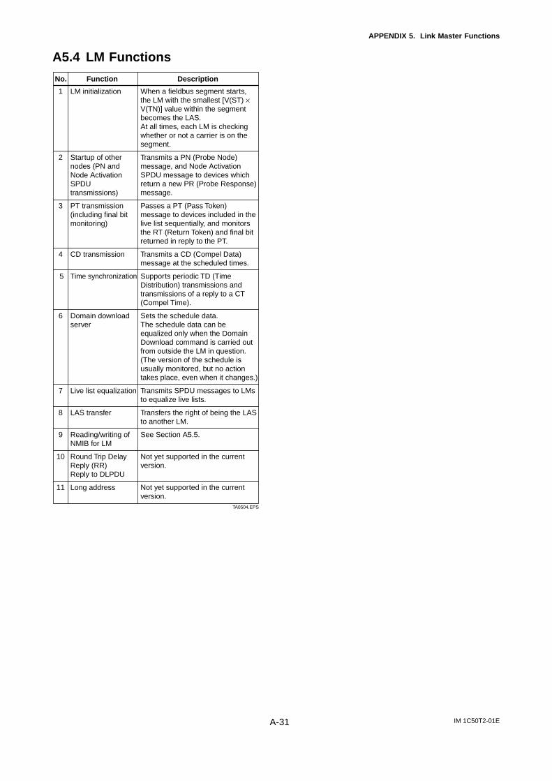
IM 1C50T2-01EA-31
APPENDIX 5. Link Master Functions
A5.4 LM Functions
No. Function Description
LM initialization
Startup of other nodes (PN and Node Activation SPDU transmissions)
PT transmission (including final bit monitoring)
CD transmission
Time synchronization
Domain download server
Live list equalization
LAS transfer
Reading/writing of NMIB for LM
Round Trip Delay Reply (RR)Reply to DLPDU
Long address
1
2
3
4
5
6
7
8
9
10
11
TA0504.EPS
When a fieldbus segment starts, the LM with the smallest [V(ST) × V(TN)] value within the segment becomes the LAS. At all times, each LM is checking whether or not a carrier is on the segment.
Transmits a PN (Probe Node) message, and Node Activation SPDU message to devices which return a new PR (Probe Response) message.
Passes a PT (Pass Token) message to devices included in the live list sequentially, and monitors the RT (Return Token) and final bit returned in reply to the PT.
Transmits a CD (Compel Data) message at the scheduled times.
Supports periodic TD (Time Distribution) transmissions and transmissions of a reply to a CT (Compel Time).
Sets the schedule data. The schedule data can be equalized only when the Domain Download command is carried out from outside the LM in question. (The version of the schedule is usually monitored, but no action takes place, even when it changes.)
Transmits SPDU messages to LMs to equalize live lists.
Transfers the right of being the LAS to another LM.
See Section A5.5.
Not yet supported in the current version.
Not yet supported in the current version.
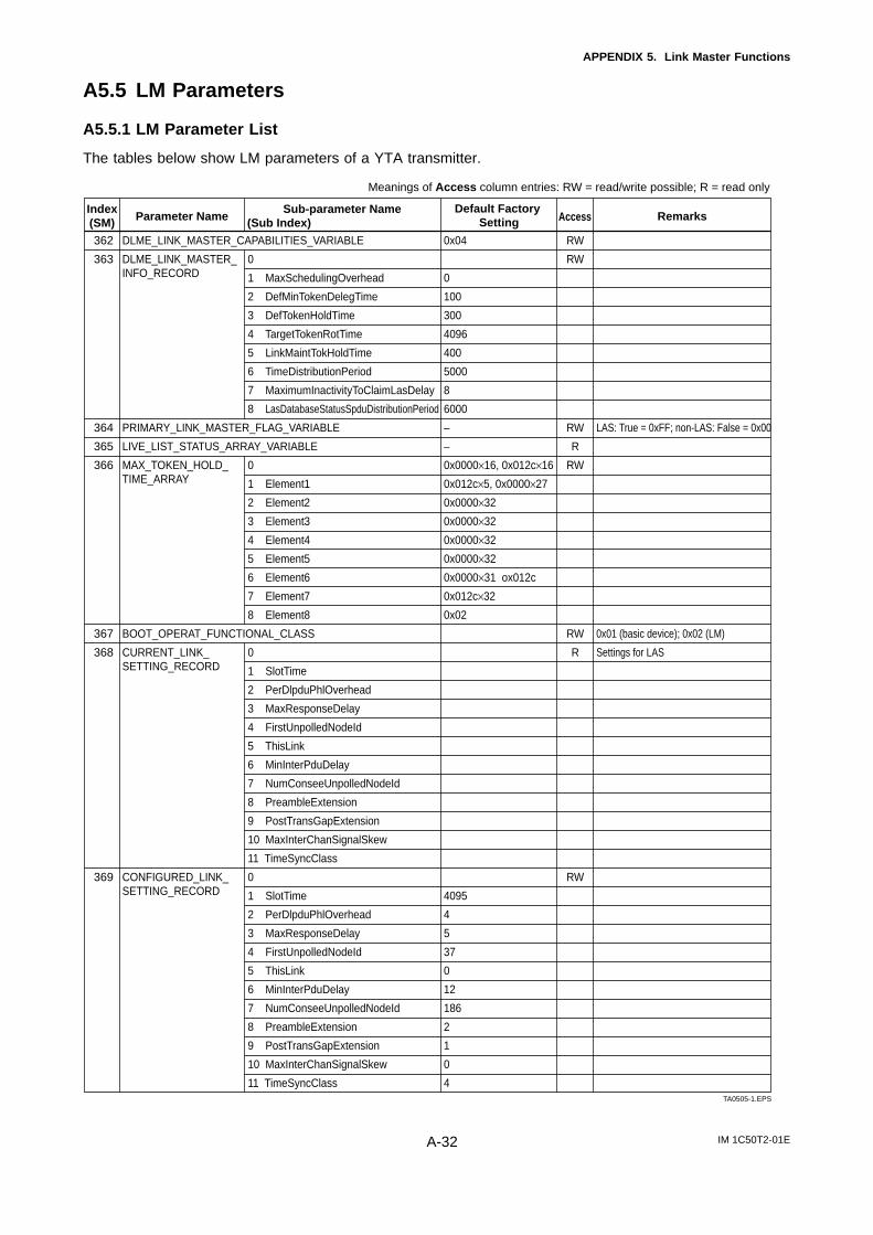
IM 1C50T2-01EA-32
APPENDIX 5. Link Master Functions
A5.5 LM Parameters
A5.5.1 LM Parameter List
The tables below show LM parameters of a YTA transmitter.
362
363
364
365
366
367
368
369
0
1 MaxSchedulingOverhead
2 DefMinTokenDelegTime
3 DefTokenHoldTime
4 TargetTokenRotTime
5 LinkMaintTokHoldTime
6 TimeDistributionPeriod
7 MaximumInactivityToClaimLasDelay
8 LasDatabaseStatusSpduDistributionPeriod
0
1 Element1
2 Element2
3 Element3
4 Element4
5 Element5
6 Element6
7 Element7
8 Element8
0
1 SlotTime
2 PerDlpduPhlOverhead
3 MaxResponseDelay
4 FirstUnpolledNodeId
5 ThisLink
6 MinInterPduDelay
7 NumConseeUnpolledNodeId
8 PreambleExtension
9 PostTransGapExtension
10 MaxInterChanSignalSkew
11 TimeSyncClass
0
1 SlotTime
2 PerDlpduPhlOverhead
3 MaxResponseDelay
4 FirstUnpolledNodeId
5 ThisLink
6 MinInterPduDelay
7 NumConseeUnpolledNodeId
8 PreambleExtension
9 PostTransGapExtension
10 MaxInterChanSignalSkew
11 TimeSyncClass
0x04
0
100
300
4096
400
5000
8
6000
–
–
0x0000×16, 0x012c×16
0x012c×5, 0x0000×27
0x0000×32
0x0000×32
0x0000×32
0x0000×32
0x0000×31 ox012c
0x012c×32
0x02
4095
4
5
37
0
12
186
2
1
0
4
LAS: True = 0xFF; non-LAS: False = 0x00
0x01 (basic device); 0x02 (LM)
Settings for LAS
RW
RW
RW
R
RW
RW
R
RW
TA0505-1.EPS
Meanings of Access column entries: RW = read/write possible; R = read only
DLME_LINK_MASTER_CAPABILITIES_VARIABLE
DLME_LINK_MASTER_INFO_RECORD
PRIMARY_LINK_MASTER_FLAG_VARIABLE
LIVE_LIST_STATUS_ARRAY_VARIABLE
MAX_TOKEN_HOLD_TIME_ARRAY
BOOT_OPERAT_FUNCTIONAL_CLASS
CURRENT_LINK_SETTING_RECORD
CONFIGURED_LINK_SETTING_RECORD
Index(SM)
Sub-parameter NameAccess(Sub Index)Parameter Name
Default Factory Setting Remarks
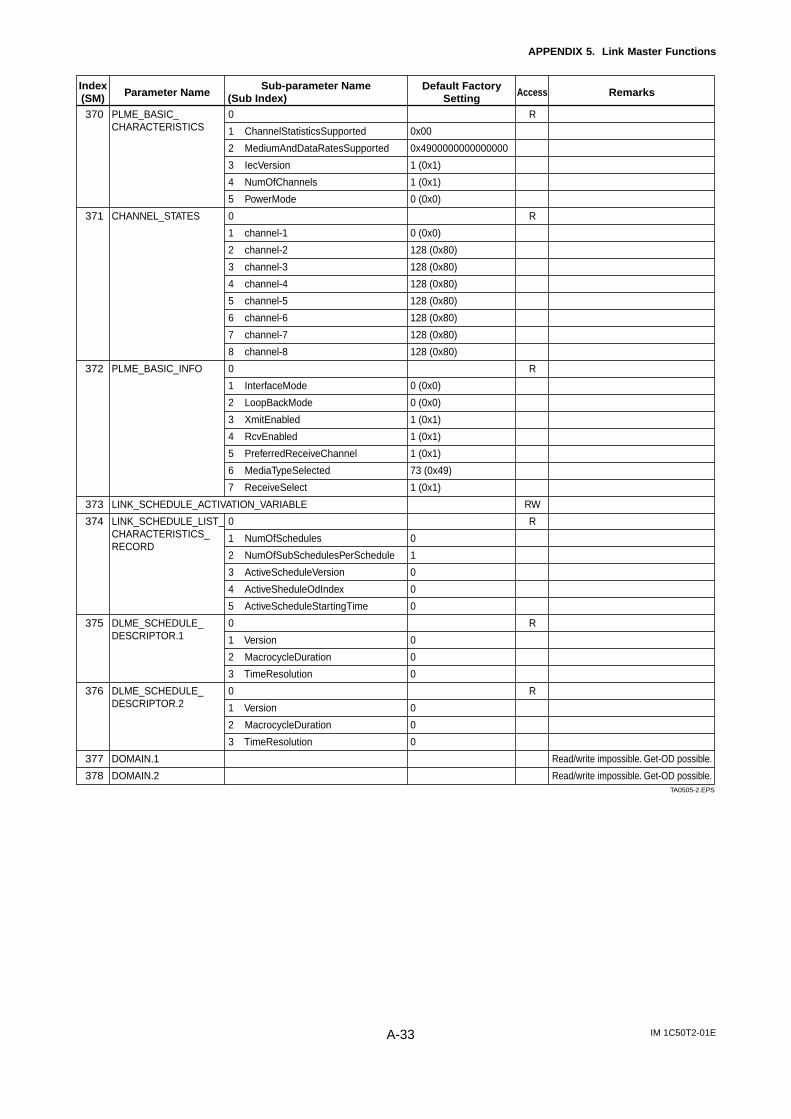
IM 1C50T2-01EA-33
APPENDIX 5. Link Master Functions
370
371
372
373
374
375
376
377
378
0
1 ChannelStatisticsSupported
2 MediumAndDataRatesSupported
3 IecVersion
4 NumOfChannels
5 PowerMode
0
1 channel-1
2 channel-2
3 channel-3
4 channel-4
5 channel-5
6 channel-6
7 channel-7
8 channel-8
0
1 InterfaceMode
2 LoopBackMode
3 XmitEnabled
4 RcvEnabled
5 PreferredReceiveChannel
6 MediaTypeSelected
7 ReceiveSelect
0
1 NumOfSchedules
2 NumOfSubSchedulesPerSchedule
3 ActiveScheduleVersion
4 ActiveSheduleOdIndex
5 ActiveScheduleStartingTime
0
1 Version
2 MacrocycleDuration
3 TimeResolution
0
1 Version
2 MacrocycleDuration
3 TimeResolution
0x00
0x4900000000000000
1 (0x1)
1 (0x1)
0 (0x0)
0 (0x0)
128 (0x80)
128 (0x80)
128 (0x80)
128 (0x80)
128 (0x80)
128 (0x80)
128 (0x80)
0 (0x0)
0 (0x0)
1 (0x1)
1 (0x1)
1 (0x1)
73 (0x49)
1 (0x1)
0
1
0
0
0
0
0
0
0
0
0
Read/write impossible. Get-OD possible.
Read/write impossible. Get-OD possible.
R
R
R
RW
R
R
R
TA0505-2.EPS
Index(SM)
Sub-parameter NameAccess(Sub Index)Parameter Name
Default Factory Setting Remarks
PLME_BASIC_CHARACTERISTICS
CHANNEL_STATES
PLME_BASIC_INFO
LINK_SCHEDULE_ACTIVATION_VARIABLE
LINK_SCHEDULE_LIST_CHARACTERISTICS_RECORD
DLME_SCHEDULE_DESCRIPTOR.1
DLME_SCHEDULE_DESCRIPTOR.2
DOMAIN.1
DOMAIN.2
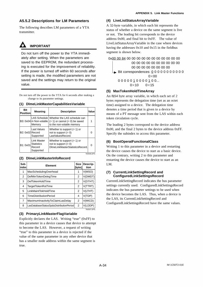
IM 1C50T2-01EA-34
APPENDIX 5. Link Master Functions
A5.5.2 Descriptions for LM Parameters
The following describes LM parameters of a YTAtransmitter.
IMPORTANT
Do not turn off the power to the YTA immedi-ately after setting. When the parameters aresaved to the EEPROM, the redundant process-ing is executed for the improvement of reliability.If the power is turned off within 60 seconds aftersetting is made, the modified parameters are notsaved and the settings may return to the originalvalue.
Do not turn off the power to the YTA for 6 seconds after making achange to its parameter settings.
(1) DlmeLinkMasterCapabilitiesVariable
MeaningBit Position
ValueDescription
1
0
0
LAS Schedule in Non-volatile Memory
Last Values Record Supported
Link Master Statistics Record Supported
Whether the LAS schedule can (= 1) or cannot (= 0) be saved to the non-volatile memory
Whether to support (= 1) or not to support (= 0) LastValuesRecord.
Whether to support (= 1) or not to support (= 0) DlmeLinkMasterStatisticsRecord.
B3: 0x04
B2: 0x02
B1: 0x01
TA0506.EPS
(2) DlmeLinkMasterInfoRecord
ElementSub-index
Descrip-tion
Size[bytes]
1
2
2
2
2
4
2
2
V(MSO)
V(DMDT)
V(DTHT)
V(TTRT)
V(LTHT)
V(TDP)
V(MICD)
V(LDDP)
MaxSchedulingOverhead
DefMinTokenDelegTime
DefTokenHoldTime
TargetTokenRotTime
LinkMaintTokHoldTime
TimeDistributionPeriod
MaximumInactivityToClaimLasDelay
LasDatabaseStatusSpduDistributionPeriod
1
2
3
4
5
6
7
8TA0507.EPS
(3) PrimaryLinkMasterFlagVariableExplicitly declares the LAS. Writing “true” (0xFF) tothis parameter in a device causes that device to attemptto become the LAS. However, a request of writing“true” to this parameter in a device is rejected if thevalue of the same parameter in any other device thathas a smaller node address within the same segment istrue.
(4) LiveListStatusArrayVariableA 32-byte variable, in which each bit represents thestatus of whether a device on the same segment is liveor not. The leading bit corresponds to the deviceaddress 0x00, and final bit to 0xFF. The value ofLiveListStatusArrayVariable in the case where deviceshaving the addresses 0x10 and 0x15 in the fieldbussegment is shown below.
0x00 00 84 00 00 00 00 00 00 00 00 00 00 0000 00 00 00 00 00 00 00 00 0000 00 00 00 00 00 00 00
Bit correspondences: 0 0 0 0 0 0 0 0 0 0 0 000
0 0 0 0 0 1 0 0 0 0 1 0 0... 010 015
(5) MaxTokenHoldTimeArrayAn 8(64 byte array variable, in which each set of 2bytes represents the delegation time (set as an octettime) assigned to a device. The delegation timedenotes a time period that is given to a device bymeans of a PT message sent from the LAS within eachtoken circulation cycle.
The leading 2 bytes correspond to the device address0x00, and the final 2 bytes to the device address 0xFF.Specify the subindex to access this parameter.
(6) BootOperatFunctionalClassWriting 1 to this parameter in a device and restartingthe device causes the device to start as a basic device.On the contrary, writing 2 to this parameter andrestarting the device causes the device to start as anLM.
(7) CurrentLinkSettingRecord andConfiguredLinkSettingsRecord
CurrentLinkSettingRecord indicates the bus parametersettings currently used. ConfiguredLinkSettingsRecordindicates the bus parameter settings to be used whenthe device becomes the LAS. Thus, when a device isthe LAS, its CurrentLinkSettingRecord andConfiguredLinkSettingsRecord have the same values.

IM 1C50T2-01EA-35
APPENDIX 5. Link Master Functions
ElementSub-index
Descrip-tion
Size[bytes]
2
1
1
1
2
1
1
1
1
1
1
V(ST)
V(PhLO)
V(MRD)
V(FUN)
V(TL)
V(MID)
V(NUN)
V(PhPE)
V(PhGE)
V(PhIS)
V(TSC)
SlotTime
PerDlpduPhlOverhead
MaxResponseDelay
FirstUnpolledNodeId
ThisLink
MinInterPduDelay
NumConsecUnpolledNodeId
PreambleExtension
PostTransGapExtension
MaxInterChanSignalSkew
TimeSyncClass
1
2
3
4
5
6
7
8
9
10
11TA0508.EPS
(8) DlmeBasicInfo
Element DescriptionSub-index
Size[bytes]
2
1
1
1
2
1
1
1
1
1
Indicates the capability value for V(ST) of the device.
V(PhLO)
Indicates the capability value for V(MRD) of the device.
V(TN), node address
V(TL), link-id
Indicates the capability value for V(MID) of the device.
Indicates the capability value for V(TSC) of the device.
V(PhPE)
V(PhGE)
V(PhIS)
SlotTime
PerDlpduPhlOverhead
MaxResponseDelay
ThisNode
ThisLink
MinInterPduDelay
TimeSyncClass
PreambleExtension
PostTransGapExtension
MaxInterChanSignalSkew
1
2
3
4
5
6
7
8
9
10TA0509.EPS
(9) PlmeBasicCharacteristics
Element Value DescriptionSub-index
Size[bytes]
1
8
2
1
1
Statistics data are not supported.
Wire medium, voltage mode, and 31.25 kbps are supported.
IEC 4.3 is supported.
0: Bus-powered; 1: Self-powered
ChannelStatisticsSupported
MediumAndDataRatesSupported
IceVersion
NumOfChannels
PowerMode
0
0x49 00 00 00 00 00 00 00
0x0403
1
0
1
2
3
4
5
TA0510.EPS
(10) ChannelStates
Element Value DescriptionSub-index
Size[bytes]
1
1
1
1
1
1
1
1
In Use, No Bad since last read, No Silent since last read, No Jabber since last read, Tx Good, Rx Good
Unused
Unused
Unused
Unused
Unused
Unused
Unused
Channel 1
Channel 2
Channel 3
Channel 4
Channel 5
Channel 6
Channel 7
Channel 8
0x00
0x80
0x80
0x80
0x80
0x80
0x80
0x80
1
2
3
4
5
6
7
8TA0511.EPS
(11) PlmeBasicInfo
Element Value DescriptionSub-index
Size[bytes]
1
1
1
1
1
1
1
0: Half duplex; 1: Full duplex
0: Disabled; 1: MAU; 2: MDS
Channel 1 is enabled.
Channel 1 is enabled.
Channel 1 is used for reception.
Wire medium, voltage mode, and 31.25 kbps are selected.
Channel 1 is used for reception.
InterfaceMode
LoopBackMode
XmitEnabled
RcvEnebled
PreferredReceiveChannel
MediaTypeSelected
ReceiveSelect
0
0
0x01
0x01
0x01
0x49
0x01
1
2
3
4
5
6
7
TA0512.EPS
(12) LinkScheduleActivationVariableWriting the version number of an LAS schedule, whichhas already been downloaded to the domain, to thisparameter causes the corresponding schedule to beexecuted. On the other hand, writing 0 to this param-eter stops execution of the active schedule.
(13) LinkScheduleListCharacteristicsRecord
Element DescriptionSub-index
Size[bytes]
1
1
2
2
6
Indicates the total number of LAS schedules that have been downloaded to the domain.
Indicates the maximum number of sub-schedules an LAS schedule can contain. (This is fixed to 1 in the Yokogawa communication stacks.)
Indicates the version number of the schedule currently executed.
Indicates the index number of the domain that stores the schedule currently executed.
Indicates the time when the current schedule began being executed.
NumOfSchedules
NumOfSub SchedulesPerSchedule
ActiveScheduleVersion
ActiveScheduleOdIndex
ActiveScheduleStaringTime
1
2
3
4
5
TA0513.EPS
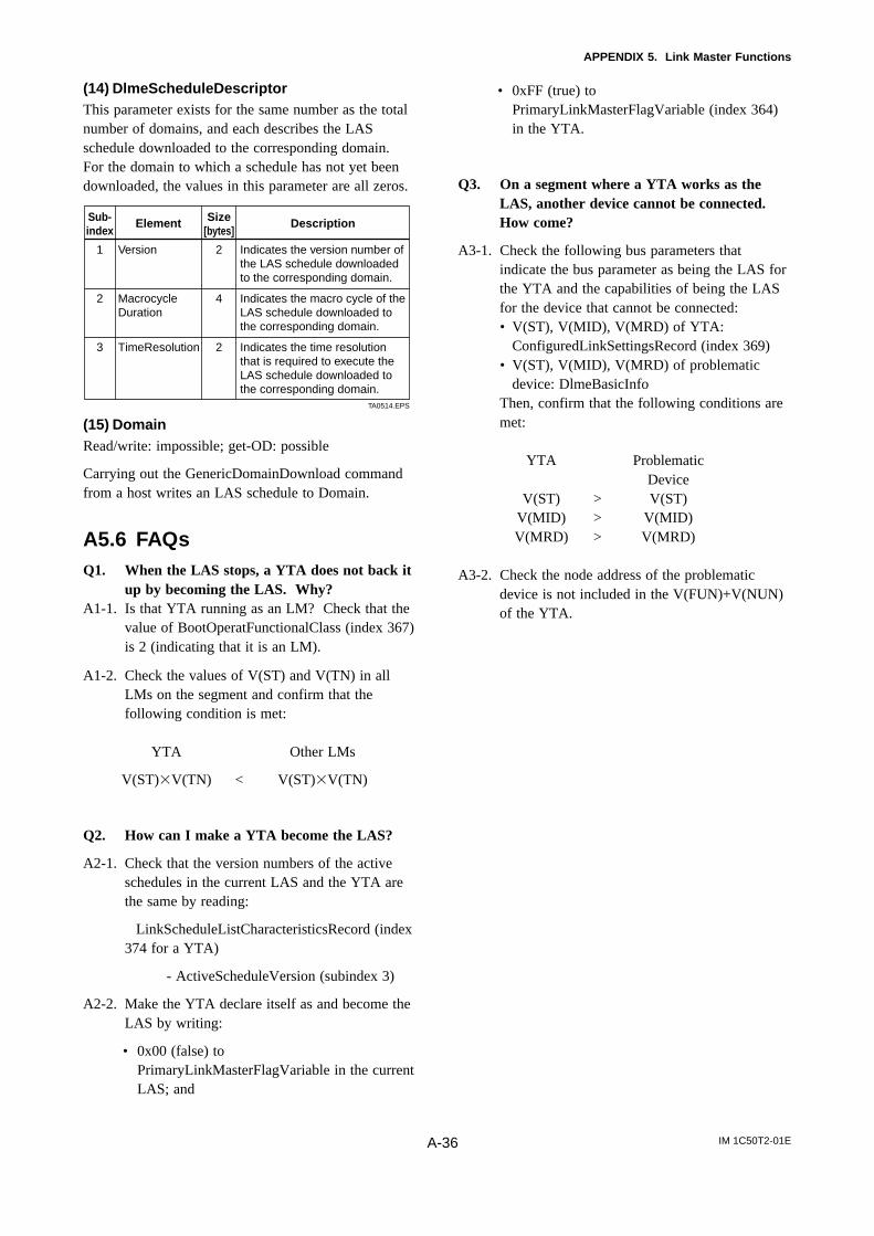
IM 1C50T2-01EA-36
APPENDIX 5. Link Master Functions
(14) DlmeScheduleDescriptorThis parameter exists for the same number as the totalnumber of domains, and each describes the LASschedule downloaded to the corresponding domain.For the domain to which a schedule has not yet beendownloaded, the values in this parameter are all zeros.
Element DescriptionSub-index
Size[bytes]
2
4
2
Indicates the version number of the LAS schedule downloaded to the corresponding domain.
Indicates the macro cycle of the LAS schedule downloaded to the corresponding domain.
Indicates the time resolution that is required to execute the LAS schedule downloaded to the corresponding domain.
Version
MacrocycleDuration
TimeResolution
1
2
3
TA0514.EPS
(15) DomainRead/write: impossible; get-OD: possible
Carrying out the GenericDomainDownload commandfrom a host writes an LAS schedule to Domain.
A5.6 FAQsQ1. When the LAS stops, a YTA does not back it
up by becoming the LAS. Why?A1-1. Is that YTA running as an LM? Check that the
value of BootOperatFunctionalClass (index 367)is 2 (indicating that it is an LM).
A1-2. Check the values of V(ST) and V(TN) in allLMs on the segment and confirm that thefollowing condition is met:
YTA Other LMs
V(ST)V(TN) < V(ST)V(TN)
Q2. How can I make a YTA become the LAS?
A2-1. Check that the version numbers of the activeschedules in the current LAS and the YTA arethe same by reading:
LinkScheduleListCharacteristicsRecord (index374 for a YTA)
- ActiveScheduleVersion (subindex 3)
A2-2. Make the YTA declare itself as and become theLAS by writing:
• 0x00 (false) toPrimaryLinkMasterFlagVariable in the currentLAS; and
• 0xFF (true) toPrimaryLinkMasterFlagVariable (index 364)in the YTA.
Q3. On a segment where a YTA works as theLAS, another device cannot be connected.How come?
A3-1. Check the following bus parameters thatindicate the bus parameter as being the LAS forthe YTA and the capabilities of being the LASfor the device that cannot be connected:• V(ST), V(MID), V(MRD) of YTA:
ConfiguredLinkSettingsRecord (index 369)• V(ST), V(MID), V(MRD) of problematic
device: DlmeBasicInfoThen, confirm that the following conditions aremet:
YTA ProblematicDevice
V(ST) > V(ST)V(MID) > V(MID)V(MRD) > V(MRD)
A3-2. Check the node address of the problematicdevice is not included in the V(FUN)+V(NUN)of the YTA.

IM 1C50T2-01E
REVISION RECORDTitle: YTA Series Temperature Transmitter Fieldbus CommunicationManual No.: IM 1C50T2-01E
Edition Date Page Revised Item
1st Oct. 2000 New publication
REVISION RECORD.EPS


![User's AXF Manual Magnetic Flowmeter Integral Flowmeter ... · Magnetic Flowmeter Integral Flowmeter/ Remote Flowtube [Hardware Edition] IM 01E20D01-01E IM 01E20D01-01E 7th Edition](https://img.pdfslide.us/doc/110x75/5e9c29fa54300501b21ae83a/users-axf-manual-magnetic-flowmeter-integral-flowmeter-magnetic-flowmeter-integral.jpg)

![Model DC402G Converter for Dual Cell Conductivity and ... · User’s Manual Model DC402G Converter for Dual Cell Conductivity and Resistivity [Style: S2] IM 12D08E02-01E IM 12D08E02-01E](https://img.pdfslide.us/doc/110x75/5ac2cf3c7f8b9a357e8e6c4f/model-dc402g-converter-for-dual-cell-conductivity-and-s-manual-model-dc402g.jpg)


![User’s - Yokogawa Electric s Manual Yokogawa Electric Corporation IM 21B3C1-01E VP200 Current-to-Pneumatic Positioner [Style : S3] IM 21B3C1-01E 7th Edition IM 21B3C1-01E i INTRODUCTION](https://img.pdfslide.us/doc/110x75/5abb71277f8b9a441d8cd2f8/users-yokogawa-electric-s-manual-yokogawa-electric-corporation-im-21b3c1-01e.jpg)


![User’s Manual YTA Series Temperature Transmitters ...cdn2.us.yokogawa.com/IM01C50B01-01E.pdf · User’s Manual YTA Series Temperature Transmitters (Hardware) [Style: S3] IM 01C50B01-01E](https://img.pdfslide.us/doc/110x75/5a79fe887f8b9adf228c43aa/users-manual-yta-series-temperature-transmitters-cdn2us-s-manual-yta-series.jpg)