Embed Size (px)
Citation preview

Yokogawa Electric Corporation
User’sManual
IM 01E20F02-01E
ADMAG AXF SeriesFOUNDATION Fieldbus Communication TypeMagnetic Flowmeter
IM 01E20F02-01E4th Edition

i
CONTENTS
IM 01E20F02-01E4th Edition: Sep. 2015All Rights Reserved, Copyright © 2006, Yokogawa Electric Corporation
CONTENTS
1. INTRODUCTION............................................................................................ 1-1
1.1 Using the Magnetic Flowmeter Safety ................................................ 1-21.2 Warranty .............................................................................................. 1-31.3 Combination Remote Flowtubes ......................................................... 1-4
2. ABOUT FIELDBUS ....................................................................................... 2-1
2.1 Outline ................................................................................................. 2-12.2 Internal Structure of AXF .................................................................... 2-1
2.2.1 System/network Management VFD ............................................. 2-12.2.2 Function Block VFD ..................................................................... 2-1
2.3 Logical Structure of Each Block .......................................................... 2-12.4 Wiring System Configuration .............................................................. 2-2
3. GETTING STARTED ..................................................................................... 3-1
3.1 Connection of Devices ........................................................................ 3-13.2 Host Setting ......................................................................................... 3-23.3 Bus Power ON .................................................................................... 3-33.4 Integration of DD ................................................................................. 3-33.5 Reading the Parameters ..................................................................... 3-33.6 Continuous Record of Values ............................................................. 3-43.7 Generation of Alarm ............................................................................ 3-4
4. CONFIGURATION ......................................................................................... 4-1
4.1 Network Design ................................................................................... 4-14.2 Network Definition ............................................................................... 4-14.3 Definition of Combining Function Blocks ............................................ 4-24.4 Setting of Tags and Addresses .......................................................... 4-34.5 Communication Setting ....................................................................... 4-4
4.5.1 VCR Setting .................................................................................. 4-44.5.2 Function Block Execution Control ................................................ 4-5
4.6 Block Setting ....................................................................................... 4-54.6.1 Link Object ................................................................................... 4-54.6.2 Trend Object ................................................................................. 4-64.6.3 View Object .................................................................................. 4-64.6.4 Function Block Parameters ........................................................ 4-11
5. EXPLANATION OF BASIC ITEMS............................................................... 5-1
5.1 Outline ................................................................................................. 5-15.2 Setting and Changing Parameters for the Whole Process ................ 5-15.3 Transducer Block Parameters ............................................................ 5-25.4 AI Function Block Parameters ............................................................ 5-45.5 DI Function Block Parameters ............................................................ 5-75.6 Integral LCD Indicator ......................................................................... 5-8
5.6.1 Flow Data Display ........................................................................ 5-85.6.2 Display Modes ............................................................................ 5-10

ii
CONTENTS
IM 01E20F02-01E
6. IN-PROCESS OPERATION .......................................................................... 6-1
6.1 Mode Transition .................................................................................. 6-16.2 Generation of Alarm ............................................................................ 6-1
6.2.1 Indication of Alarm ....................................................................... 6-16.2.2 Alarms and Events ....................................................................... 6-1
6.3 Simulation Function ............................................................................. 6-2
7. DEVICE INFORMATION ............................................................................... 7-1
7.1 DEVICE STATUS ................................................................................ 7-17.2 Status of each parameter in failure mode .......................................... 7-4
8. PARAMETER LISTS ..................................................................................... 8-1
8.1 Resource Block ................................................................................... 8-18.2 Transducer Block ................................................................................ 8-48.3 AI Function Block ................................................................................ 8-98.4 Dl Function Block .............................................................................. 8-11
9. GENERAL SPECIFICATIONS ...................................................................... 9-1
9.1 STANDARD SPECIFICATIONS ......................................................... 9-19.2 OPTIONAL SPECIFICATIONS ........................................................... 9-29.3 TERMINAL CONNECTION ................................................................. 9-3
10. MAINTENANCE........................................................................................... 10-1
APPENDIX 1. APPLICATION, SETTING AND CHANGEOF BASIC PARAMETERS ......................................................... A-1
A1.1 Applications and Selection of Basic Parameters ................................ A-1A1.2 Setting and Change of Basic Parameters .......................................... A-2A1.3 Setting the AI Function Block ............................................................. A-3A1.4 Setting the Transducer Block .............................................................. A-4A1.5 Setting the Integrator (IT) Function Block ........................................... A-5A1.6 Setting the DI Function Block ............................................................. A-5
iii
CONTENTS
IM 01E20F02-01E
APPENDIX 2. INTEGRATOR (IT) BLOCK ....................................................... A-6
A2.1 Schematic Diagram of Integrator Block .............................................. A-6A2.2 Input Process Section ......................................................................... A-7
A2.2.1 Determining Input Value Statuses ............................................... A-7A2.2.2 Converting the Rate ..................................................................... A-7A2.2.3 Converting Accumulation ............................................................. A-8A2.2.4 Determining the Input Flow Direction ........................................... A-8
A2.3 Adder ................................................................................................... A-8A2.3.1 Status of Value after Addition ...................................................... A-8A2.3.2 Addition ......................................................................................... A-9
A2.4 Integrator ............................................................................................. A-9A2.5 Output Process ................................................................................. A-11
A2.5.1 Status Determination .................................................................. A-11A2.5.2 Determining the Output Value .................................................... A-12A2.5.3 Mode Handling ........................................................................... A-13
A2.6 Reset ................................................................................................. A-13A2.6.1 Reset Trigger .............................................................................. A-13A2.6.2 Reset Timing .............................................................................. A-13A2.6.3 Reset Process ............................................................................ A-14
A2.7 List of Integrator Block Parameters .................................................. A-15
APPENDIX 3. ARITHMETIC (AR) BLOCK ..................................................... A-17
A3.1 Schematic Diagram of Arithmetic Block ........................................... A-17A3.2 Input Section ..................................................................................... A-18
A3.2.1 Main Inputs ................................................................................. A-18A3.2.2 Auxiliary Inputs ........................................................................... A-18A3.2.3 INPUT_OPTS ............................................................................. A-19A3.2.4 Relationship between the Main Inputs and PV.......................... A-19
A3.3 Computation Section ......................................................................... A-20A3.3.1 Computing Equations ................................................................. A-20A3.3.2 Compensated Values ................................................................. A-20A3.3.3 Average Calculation ................................................................... A-20
A3.4 Output Section .................................................................................. A-20A3.4.1 Mode Handling ........................................................................... A-21A3.4.2 Status Handling .......................................................................... A-21
A3.5 List of the Arithmetic Block Parameters ........................................... A-22
APPENDIX 4. LINK MASTER FUNCTIONS ................................................... A-24
A4.1 Link Active Scheduler ....................................................................... A-24A4.2 Link Master ........................................................................................ A-24A4.3 Transfer of LAS ................................................................................. A-25A4.4 LM Functions ..................................................................................... A-26A4.5 LM Parameters .................................................................................. A-27
A4.5.1 LM Parameter List ...................................................................... A-27A4.5.2 Descriptions for LM Parameters ................................................ A-29
A4.6 FAQs ................................................................................................. A-31
iv
CONTENTS
IM 01E20F02-01E
APPENDIX 5. PID BLOCK .............................................................................. A-32
A5.1 Function Diagram .............................................................................. A-32A5.2 Functions of PID Block ..................................................................... A-32A5.3 Parameters of PID Block .................................................................. A-33A5.4 PID Computation Details ................................................................... A-35
A5.4.1 PV-proportional and -derivative Type PID (I-PD)Control Algorithm........................................................................ A-35
A5.4.2 PID Control Parameters ............................................................. A-35A5.5 Control Output ................................................................................... A-35
A5.5.1 Velocity Type Output Action ....................................................... A-35A5.6 Direction of Control Action ................................................................ A-35A5.7 Control Action Bypass ....................................................................... A-35A5.8 Feed-forward ..................................................................................... A-36A5.9 Block Modes ...................................................................................... A-36
A5.9.1 Mode Transitions ........................................................................ A-36A5.10Bumpless Transfer ............................................................................ A-37A5.11Setpoint Limiters ............................................................................... A-37
A5.11.1 When PID Block Is in Auto Mode ............................................ A-37A5.11.2 When PID Block Is in Cas or RCas Mode ............................... A-37
A5.12External-output Tracking ................................................................... A-37A5.13Measured-value Tracking .................................................................. A-37A5.14 Initialization and Manual Fallback (IMan) ......................................... A-38A5.15Manual Fallback ................................................................................ A-38A5.16Auto Fallback .................................................................................... A-38A5.17Mode Shedding upon Computer Failure ........................................... A-39
A5.17.1 SHED_OPT .............................................................................. A-39A5.18Alarms ............................................................................................... A-39
A5.18.1 Block Alarm (BLOCK_ALM) ..................................................... A-39A5.18.2 Process Alarms ........................................................................ A-39
A5.19Example of Block Connections ......................................................... A-40A5.20View Object for PID Function Block ................................................. A-40
APPENDIX 6. SOFTWARE DOWNLOAD....................................................... A-42
A6.1 Benefits of Software Download ......................................................... A-42A6.2 Specifications .................................................................................... A-42A6.3 Preparations for Software Downloading ........................................... A-42A6.4 Software Download Sequence .......................................................... A-43A6.5 Download Files .................................................................................. A-43A6.6 Steps after Activating a Field Device ................................................ A-44A6.7 Troubleshooting ................................................................................. A-45A6.8 Resource Block’s Parameters Relating to Software Download ....... A-45A6.9 System/Network Management VFD Parameters Relating to
Software Download ........................................................................... A-47A6.10Comments on System/Network Management VFD Parameters
Relating to Software Download ........................................................ A-48
REVISION RECORD
IM 01E20F02-01E1-1
1. INTRODUCTION
1. INTRODUCTION
This manual is for the ADMAG AXF Series MagneticFlowmeter Remote Converter FOUNDATION fieldbusCommunication Type. The FOUNDATION fieldbuscommunication type is based on the same ADMAGAXF technology used in the BRAIN/HART communi-cation type, and is similar to the communication typesin terms of basic performance and operation. Thismanual describes only those topics that are required foroperation of the FOUNDATION fieldbus communicationtype. For information on the installation, wiring, andmaintenance of AXF series magnetic flowmeter, referto the user’s manual for each model (IM 01E20D01-01E or IM 01E20C02-01E).
As far terminal connection, refer to Page 9-3 of thismanual.
NOTE
When describing the model name likeAXF���C in this manual, "���" means any ofthe following.
002, 005, 010, 015, 025, 032, 040, 050, 065,080, 100, 125, 150, 200, 250, 300, 350, 400
� Regarding This Manual• This manual should be provided to the end user.• Before use, read this manual thoroughly to compre-
hend its contents.• The contents of this manual may be changed
without prior notice.• All rights are reserved. No part of this manual may
be reproduced in any form without Yokogawa'swritten permission.
• Yokogawa makes no warranty of any kind withregard to this material, including, but not limited to,implied warranties of merchantability and suitabilityfor a particular purpose.
• All reasonable effort has been made to ensure theaccuracy of the contents of this manual. However,if any errors or omissions are found, please informYokogawa.
• Yokogawa assumes no responsibilities for thisproduct except as stated in the warranty.
• The specifications covered by this manual arelimited to those for the standard type under thespecified model number break-down and do notcover custom-made instruments.
• Please note that this user's manual may not berevised for any specification changes, constructionchanges or operating part changes that are notconsidered to affect function or performance.
• If the customer or any third party is harmed by theuse of this product, Yokogawa assumes no responsi-bility for any such harm owing to any defects in theproduct which were not predictable, or for anyindirect damages.
� Safety and Modification Precautions• The following general safety precautions must be
observed during all phases of operation, service, andrepair of this instrument. Failure to comply withthese precautions or with specific WARNINGSgiven elsewhere in this manual violates safetystandards of design, manufacture, and intended useof the instrument. Yokogawa assumes no liability forthe customer's failure to comply with these require-ments. If this instrument is used in a manner notspecified in this manual, the protection provided bythis instrument may be impaired.
• Yokogawa will not be liable for malfunctions ordamage resulting from any modification made to thisinstrument by the customer.
• The following safety symbol marks are used in thisuser's manual and instrument.
WARNING
A WARNING sign denotes a hazard. It callsattention to procedure, practice, condition or thelike, which, if not correctly performed or adheredto, could result in injury or death of personnel.
CAUTION
A CAUTION sign denotes a hazard. It callsattention to procedure, practice, condition or thelike, which, if not correctly performed or adheredto, could result in damage to or destruction ofpart or all of the product.
IM 01E20F02-01E1-2
1. INTRODUCTION
IMPORTANT
An IMPORTANT sign denotes that attention isrequired to avoid damage to the instrument orsystem failure.
NOTE
A NOTE sign denotes information necessary foressential understanding of operation and fea-tures.
Protective grounding terminal
Functional grounding terminal(This terminal should not be used as a protectivegrounding terminal.)
FOUNDATION is a registered trademark of FieldbusFOUNDATION.
1.1 Using the MagneticFlowmeter Safety
(1) Installation
WARNING
• Installation of the magnetic flowmeter must beperformed by expert engineer or skilled person-nel. No operator shall be permitted to performprocedures relating to installation.
• The magnetic flowmeter must be installedwithin the specification conditions.
• The magnetic flowmeter is a heavy instrument.Be careful that no damage is caused to person-nel through accidentally dropping it, or byexerting excessive force on the magneticflowmeter. When moving the magnetic flowme-ter, always use a trolley and have at least twopeople carry it.
• When the magnetic flowmeter is processing hotfluids, the instrument itself may become ex-tremely hot. Take sufficient care not to get burnt.
• Where the fluid being processed is a toxicsubstance, avoid contact with the fluid andavoid inhaling any residual gas, even after theinstrument has been taken off the piping line formaintenance and so forth.
• Do not apply excessive weight, for example, aperson stepping on the magnetic flowmeter.
• All procedures relating to installation mustcomply with the electrical code of the countrywhere it is used.
(2) Wiring
WARNING
• The wiring of the magnetic flowmeter must beperformed by expert engineer or skilled person-nel. No operator shall be permitted to performprocedures relating to wiring.
• When connecting the wiring, check that thesupply voltage is within the range of the voltagespecified for this instrument before connectingthe power cable. In addition, check that novoltage is applied to the power cable beforeconnecting the wiring.
• The protective grounding must be connectedsecurely at the terminal with the mark toavoid danger to personnel.
(3) Operation
WARNING
• When opening the cover, wait for more than 10minutes after turning off the power. Only expertengineer or skilled personnel are permitted toopen the cover.
• Do not open the cover in wet weather or humidenvironment. When the cover is open, statedenclosure protection is not applicable.
(4) Maintenance
WARNING
• Maintenance of the magnetic flowmeter shouldbe performed by the trained personnel havingsafety standard knowledge. No operator shallbe permitted to perform any operations relatingto maintenance.
• When opening the cover, wait for more than 10minutes after turning off the power.
• Do not open the cover in wet weather or humidenvironment. When the cover is open, statedenclosure protection is not applicable.
IM 01E20F02-01E1-3
1. INTRODUCTION
• Always conform to maintenance proceduresoutlined in this manual. If necessary, contactYokogawa.
• Care should be taken to prevent the build up ofdust or other materials on the display glass andthe name plate. To clean these surfaces, use asoft, dry cloth.
(5) Explosion Protected Type Instrument
WARNING
• Magnetic flowmeters with the model nameAXF���C are products which have beencertified as explosion proof type instruments.Strict limitations are applied to the structures,installation locations, external wiring work,maintenance and repairs, etc. of these instru-ments. Sufficient care must be taken, as anyviolation of the limitations may cause danger-ous situations.Be sure to read “EXPLOSION PROTECTEDTYPE INSTRUMENT” at the user’s manual foreach model (IM 01E20D01-01E or IM01E20C02-01E), before handling the instru-ments. The description is prior to the otherdescription in this user’s manual.For TIIS flameproof type instruments, be sureto read “INSTALLATION AND OPERATINGPRECAUTIONS FOR TIIS FLAMEPROOFEQUIPMENT” at the end of the user’s manualfor each model (IM 01E20D01-01E or IM01E20C02-01E).
• Only trained persons use this instrument in theindustrial location.
• The protective grounding must be connectedto a suitable IS grounding system.
• Take care not to generate mechanical sparkwhen access to the instrument and peripheraldevices in hazardous locations.
(6) European Pressure Equipment Directive(PED)
WARNING
• When using the instrument in compliance withPED, be sure to read IM 01E20D01-01E beforeuse.
(7) Modification
WARNING
• Yokogawa will not be liable for malfunctions ordamage resulting from any modification madeto this instrument by the customer.
(8) Product DisposalThe instrument should be disposed of in accordancewith local and national legislation/regulations.
(9) Authorized Representative in EEAIn relation to the CE Marking, The authorizedrepresentative for this product in the EEA (EuropeanEconomic Area) is:Yokogawa Europe B.V.Euroweg 2, 3825 HD Amersfoort,The Netherlands
1.2 Warranty• The terms of this instrument that are guaranteed are
described in the quotation. We will make any repairsthat may become necessary during the guaranteedterm free of charge.
• Please contact our sales office if this instrumentrequires repair.
• If the instrument is faulty, contact us with concretedetails about the problem and the length of time ithas been faulty, and state the model and serialnumber. We would appreciate the inclusion ofdrawings or additional information.
• The results of our examination will determinewhether the meter will be repaired free of charge oron an at-cost basis.
� The guarantee will not apply in the followingcases:
• Damage due to negligence or insufficient mainte-nance on the part of the customer.
• Problems or damage resulting from handling,operation or storage that violates the intended useand specifications.
• Problems that result from using or performingmaintenance on the instrument in a location thatdoes not comply with the installation locationspecified by Yokogawa.
IM 01E20F02-01E1-4
1. INTRODUCTION
• Problems or damage resulting from repairs ormodifications not performed by Yokogawa orsomeone authorized by Yokogawa.
• Problems or damage resulting from inappropriatereinstallation after delivery.
• Problems or damage resulting from disasters such asfires, earthquakes, storms, floods, or lightning strikesand external causes.
� Trademarks:• All the brands or names of Yokogawa Electric’s
products used in this manual are either trademarks orregistered trademarks of Yokogawa Electric Corpo-ration.
• All other company and product names mentioned inthis manual are trade names, trademarks or regis-tered trademarks of their respective companies.
• In this manual, trademarks or registered trademarksare not marked with ™ or ®.
1.3 Combination RemoteFlowtubes
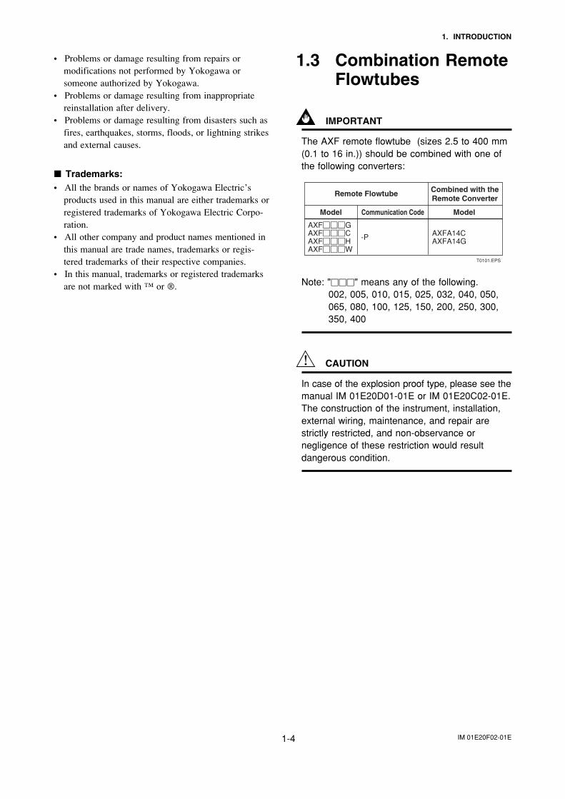
IMPORTANT
The AXF remote flowtube (sizes 2.5 to 400 mm(0.1 to 16 in.)) should be combined with one ofthe following converters:
T0101.EPS
Remote Flowtube Combined with the Remote Converter
-P AXFA14CAXFA14G
Model Communication Code Model
AXF���GAXF���CAXF���HAXF���W
Note: "���" means any of the following.002, 005, 010, 015, 025, 032, 040, 050,065, 080, 100, 125, 150, 200, 250, 300,350, 400
CAUTION
In case of the explosion proof type, please see themanual IM 01E20D01-01E or IM 01E20C02-01E.The construction of the instrument, installation,external wiring, maintenance, and repair arestrictly restricted, and non-observance ornegligence of these restriction would resultdangerous condition.
IM 01E20F02-01E2-1
2. ABOUT FIELDBUS
2. ABOUT FIELDBUS
2.1 OutlineFieldbus is a widely used bi-directional digital communi-cation protocol for field devices that enable the simulta-neous output to many types of data to the processcontrol system.
The AXF Series Fieldbus communication type employsthe specification standardized by The Fieldbus Founda-tion, and provides interoperability between Yokogawadevices and those produced by other manufacturers.Fieldbus comes with software consisting of AI, DI, IT,AR and optional PID function blocks that enable theflexible implementation of systems.
For information on other features, engineering, design,construction work, startup and maintenance ofFieldbus, refer to “Fieldbus Technical Information” (TI38K03A01-01E).
2.2 Internal Structure of AXFThe AXF contains two Virtual Field Devices (VFD)that share the following functions.
2.2.1 System/network Management VFD
• Sets node addresses and Physical Device tags (PDTag) necessary for communication.
• Controls the execution of function blocks.• Manages operation parameters and communication
resources (Virtual Communication Relationship:VCR).
2.2.2 Function Block VFD
(1)Resource block• Manages the status of AXF hardware.• Automatically informs the host of any detected
faults or other problems.
(2)Transducer block• Converts the flow sensor output to the volumetric
flow rate signal, and transfers to the AI functionblock.
• Transfers limit switch signals to DI function blocks.• Adhesion diagnosis levels are set and monitored.
(3)AI function blocks• Condition raw data from the transducer block,
including scaling and damping (with a first-orderlag), and allow input simulation.
• Outputs volumetric or mass flow rate signals.
(4)DI function blocks (two)• Limit switches for the flow rate and adhesion alarm,
warning.
(5)IT function blocks (two)• Add two main inputs and integrate them for output.
(6)AR function block• Switches two main inputs of different measurement
ranges and combines the result with three auxiliaryinputs through the selected compensation function tocalculate the output.
(7)PID function block (optional)• Performs the PID control computation based on the
deviation of the measured value from the setpoint.
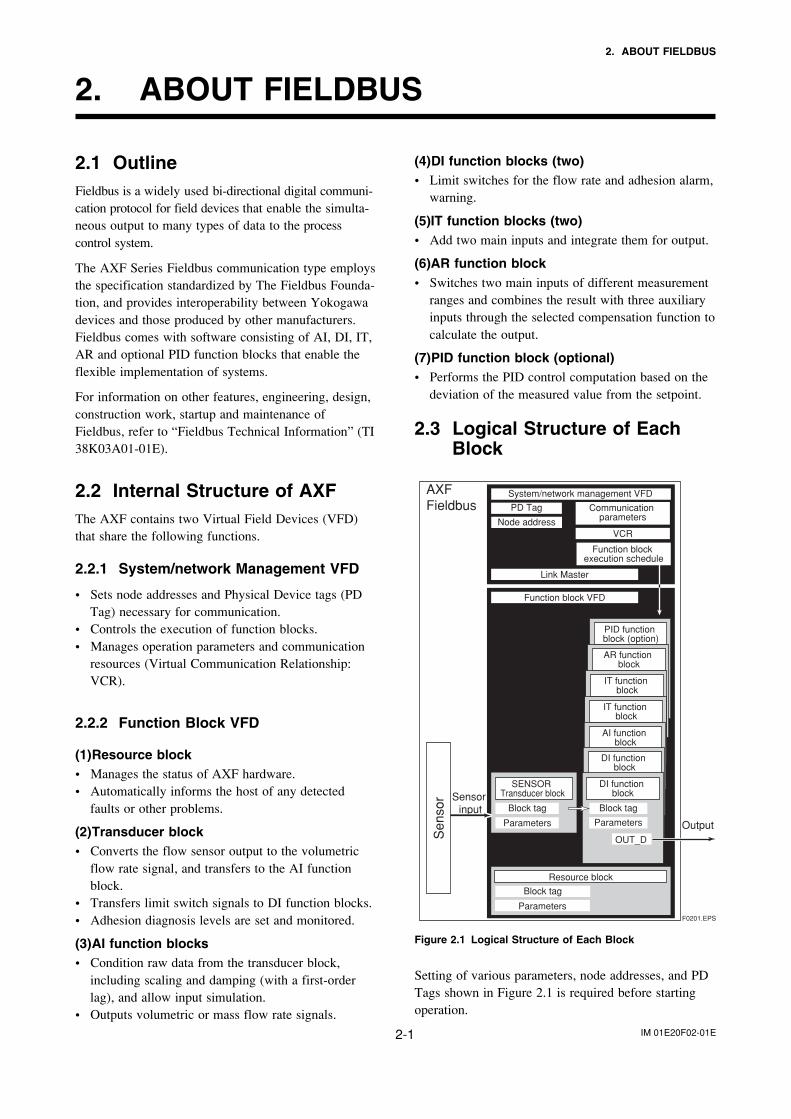
2.3 Logical Structure of EachBlock
PID function block (option)
F0201.EPS
AXF Fieldbus
System/network management VFD
Function block VFD
Link Master
PD Tag
Resource block
Block tag
Parameters
Communication parameters
VCRNode address
Function block execution schedule
AR function block
IT function block
IT function block
AI function block
DI function block
Sensor input
Output
SENSOR Transducer block
Block tag
Parameters
DI function block
Block tag
OUT_D
Parameters
Sen
sor
Figure 2.1 Logical Structure of Each Block
Setting of various parameters, node addresses, and PDTags shown in Figure 2.1 is required before startingoperation.

IM 01E20F02-01E2-2
2. ABOUT FIELDBUS
2.4 Wiring System ConfigurationThe number of devices that can be connected to asingle bus and the cable length vary depending onsystem design. When constructing systems, both thebasic and overall design must be carefully consideredto achieve optimal performance.
IM 01E20F02-01E3-1
3. GETTING STARTED
3. GETTING STARTED
Fieldbus is fully dependent upon digital communica-tion protocol and differs in operation from conven-tional 4 to 20 mA transmission and the BRAINcommunication protocol. It is recommended thatnovice users use field devices in accordance with theprocedures described in this section. The proceduresassume that field devices will be set up on a bench orin an instrument shop.
3.1 Connection of DevicesThe following are required for use with Fieldbusdevices:
• Power supply:Fieldbus requires a dedicated power supply. It isrecommended that current capacity be well over thetotal value of the maximum current consumed by alldevices (including the host). Conventional DCcurrent cannot be used as is.
• Terminator:Fieldbus requires two terminators. Refer to thesupplier for details of terminators that are attachedto the host.
• Field devices:Connect Fieldbus communication type AXF (Referto section 9.3 terminal connection). Two or moreAXF devices or other devices can be connected.
• Host:Used for accessing field devices. A dedicated host(such as DCS) is used for an instrumentation linewhile dedicated communication tools are used forexperimental purposes. For operation of the host,refer to the instruction manual for each host. Noother details on the host are given in this manual.
• Cable:Used for connecting devices. Refer to “FieldbusTechnical Information” (TI 38K03A01-01E) fordetails of instrumentation cabling. For laboratory orother experimental use, a twisted pair cable two tothree meters in length with a cross section of0.9 mm2 or more and a cycle period of within 5 cm(2 inches) may be used. Termination processingdepends on the type of device being deployed. ForAXF, use an M4 screw terminal claw. Some hostsrequire a connector.
Refer to Yokogawa when making arrangements topurchase the recommended equipment.
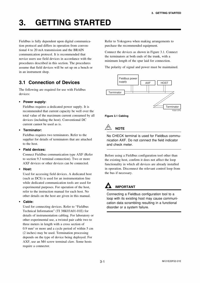
Connect the devices as shown in Figure 3.1. Connectthe terminators at both ends of the trunk, with aminimum length of the spur laid for connection.
The polarity of signal and power must be maintained.
AXF
Fieldbus power supply
Terminator
Terminator
HOST
F0301.EPS
Figure 3.1 Cabling
NOTE
No CHECK terminal is used for Fieldbus commu-nication AXF. Do not connect the field indicatorand check meter.
Before using a Fieldbus configuration tool other thanthe existing host, confirm it does not affect the loopfunctionality in which all devices are already installedin operation. Disconnect the relevant control loop fromthe bus if necessary.
IMPORTANT
Connecting a Fieldbus configuration tool to aloop with its existing host may cause communi-cation data scrambling resulting in a functionaldisorder or a system failure.
IM 01E20F02-01E3-2
3. GETTING STARTED
3.2 Host SettingTo activate Fieldbus, the following settings arerequired for the host.
IMPORTANT
Do not turn off the power immediately aftersetting. When the parameters are saved to theEEPROM, the redundant processing is executedfor an improvement of reliability. If the power isturned off within 60 seconds after setting ismade, the modified parameters are not savedand the settings may return to the originalvalues.
Table 3.1 Operation Parameters
T0301.EPS
Symbol Parameter Description and Settings
Minimum value of communication data intervals. Unit of time is in octets (256 µs). Set the maximum specification for all devices. For AXF, set a value of 4 or greater.
Indicates the time necessary for immediate reply of the device. Unit of time is in octets (256 µs). Set maximum specification for all devices. For AXF, set a value of 4 or greater.
Slot-TimeV (ST)
First-Unpolled-Node
Minimum-Inter-PDU-Delay
Maximum-Reply-Delay
Unused address range.
Indicate the address next to the address range used by the host. Set 0�15 or greater.
Number-of-consecutive-Unpolled-Node
The worst case time elapsed until a reply is recorded. The unit is Slot-time; set the value so that V (MRD) �V (ST) is the maximum value of the specification for all devices. For AXF, the setting must be a value of 12 or greater.
V (MRD)
V (MID)
V (FUN)
V (NUN)
Not used0x00
0xF70xF8
0x0F0x10
0x130x14
0xFB0xFC
0xFF
V(FUN)
V(FUN)�V(NUN)
LM device
Bridge device
Unused V(NUN)
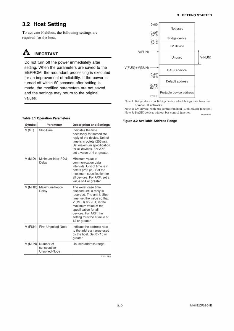
Note 1: Bridge device: A linking device which brings data from one or more H1 networks.
Note 2: LM device: with bus control function (Link Master function)Note 3: BASIC device: without bus control function
BASIC device
Default address
Portable device address
F0302.EPS
Figure 3.2 Available Address Range
IM 01E20F02-01E3-3
3. GETTING STARTED
3.3 Bus Power ONTurn on the power of the host and the bus and also thepower for the AXF. Where the AXF is equipped withan LCD indicator, first all segments are lit, then thedisplay begins to operate.
Using the host device display function, check that theAXF is in operation on the bus.
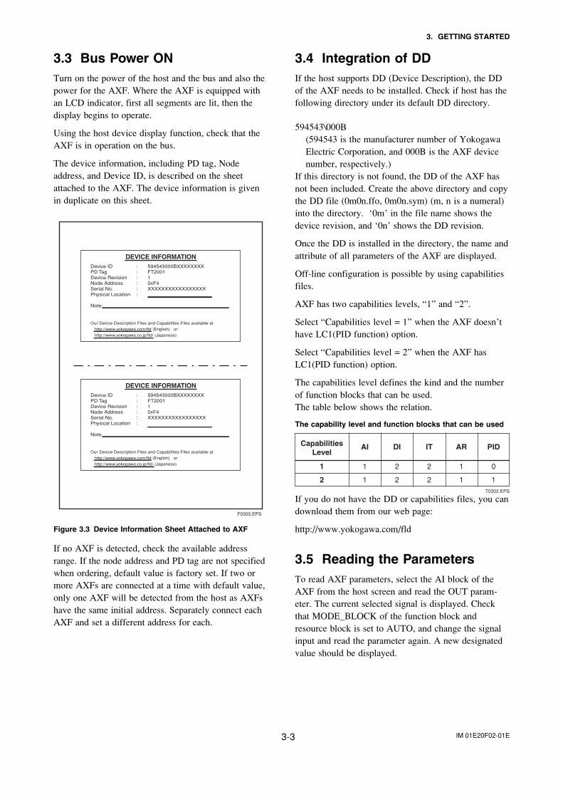
The device information, including PD tag, Nodeaddress, and Device ID, is described on the sheetattached to the AXF. The device information is givenin duplicate on this sheet.
DEVICE INFORMATIONDevice ID : 594543000BXXXXXXXXPD Tag : FT2001Device Revision : 1Node Address : 0xF4Serial No. : XXXXXXXXXXXXXXXXXPhysical Location :
Note:
Our Device Description Files and Capabilities Files available at
http://www.yokogawa.com/fld (English) or
http://www.yokogawa.co.jp/fld/ (Japanese)
F0303.EPS
Figure 3.3 Device Information Sheet Attached to AXF
If no AXF is detected, check the available addressrange. If the node address and PD tag are not specifiedwhen ordering, default value is factory set. If two ormore AXFs are connected at a time with default value,only one AXF will be detected from the host as AXFshave the same initial address. Separately connect eachAXF and set a different address for each.
3.4 Integration of DDIf the host supports DD (Device Description), the DDof the AXF needs to be installed. Check if host has thefollowing directory under its default DD directory.
594543\000B(594543 is the manufacturer number of YokogawaElectric Corporation, and 000B is the AXF devicenumber, respectively.)
If this directory is not found, the DD of the AXF hasnot been included. Create the above directory and copythe DD file (0m0n.ffo, 0m0n.sym) (m, n is a numeral)into the directory. ‘0m’ in the file name shows thedevice revision, and ‘0n’ shows the DD revision.
Once the DD is installed in the directory, the name andattribute of all parameters of the AXF are displayed.
Off-line configuration is possible by using capabilitiesfiles.
AXF has two capabilities levels, “1” and “2”.
Select “Capabilities level = 1” when the AXF doesn’thave LC1(PID function) option.
Select “Capabilities level = 2” when the AXF hasLC1(PID function) option.
The capabilities level defines the kind and the numberof function blocks that can be used.The table below shows the relation.
The capability level and function blocks that can be used
T0302.EPS
1
AI DI IT AR PIDCapabilities Level
1
2
2 2 1 0
1 2 2 1 1
If you do not have the DD or capabilities files, you candownload them from our web page:
http://www.yokogawa.com/fld
3.5 Reading the ParametersTo read AXF parameters, select the AI block of theAXF from the host screen and read the OUT param-eter. The current selected signal is displayed. Checkthat MODE_BLOCK of the function block andresource block is set to AUTO, and change the signalinput and read the parameter again. A new designatedvalue should be displayed.
IM 01E20F02-01E3-4
3. GETTING STARTED
3.6 Continuous Record of ValuesIf the host has a function that continuously records theindications, use this function to list the indications(values). Depending on the host being used, it may benecessary to set the schedule of Publish (the functionthat transmits the indication on a periodic basis).
3.7 Generation of AlarmGeneration of an alarm can be attempted from AXF.Block alarm, Output limit alarm, and Update alarm areinformed to the host. When generating alarm, a LinkObject and a VCR Static Entry need to be set. Fordetails of Link Object and VCR Static Entry, refer tosection 4.6.1 Link object and section 4.5.1 VCRSetting.
IM 01E20F02-01E4-1
4. CONFIGURATION
4. CONFIGURATION
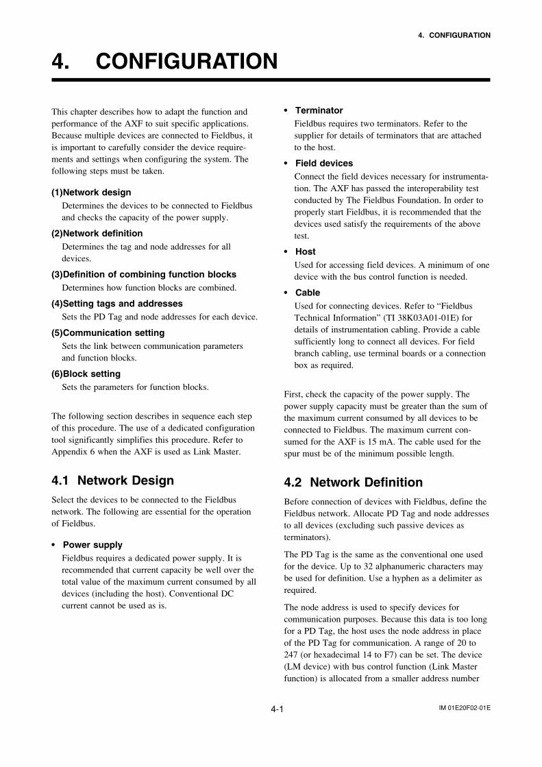
This chapter describes how to adapt the function andperformance of the AXF to suit specific applications.Because multiple devices are connected to Fieldbus, itis important to carefully consider the device require-ments and settings when configuring the system. Thefollowing steps must be taken.
(1)Network designDetermines the devices to be connected to Fieldbusand checks the capacity of the power supply.
(2)Network definitionDetermines the tag and node addresses for alldevices.
(3)Definition of combining function blocksDetermines how function blocks are combined.
(4)Setting tags and addressesSets the PD Tag and node addresses for each device.
(5)Communication settingSets the link between communication parametersand function blocks.
(6)Block settingSets the parameters for function blocks.
The following section describes in sequence each stepof this procedure. The use of a dedicated configurationtool significantly simplifies this procedure. Refer toAppendix 6 when the AXF is used as Link Master.
4.1 Network DesignSelect the devices to be connected to the Fieldbusnetwork. The following are essential for the operationof Fieldbus.
• Power supplyFieldbus requires a dedicated power supply. It isrecommended that current capacity be well over thetotal value of the maximum current consumed by alldevices (including the host). Conventional DCcurrent cannot be used as is.
• TerminatorFieldbus requires two terminators. Refer to thesupplier for details of terminators that are attachedto the host.
• Field devicesConnect the field devices necessary for instrumenta-tion. The AXF has passed the interoperability testconducted by The Fieldbus Foundation. In order toproperly start Fieldbus, it is recommended that thedevices used satisfy the requirements of the abovetest.
• HostUsed for accessing field devices. A minimum of onedevice with the bus control function is needed.
• CableUsed for connecting devices. Refer to “FieldbusTechnical Information” (TI 38K03A01-01E) fordetails of instrumentation cabling. Provide a cablesufficiently long to connect all devices. For fieldbranch cabling, use terminal boards or a connectionbox as required.
First, check the capacity of the power supply. Thepower supply capacity must be greater than the sum ofthe maximum current consumed by all devices to beconnected to Fieldbus. The maximum current con-sumed for the AXF is 15 mA. The cable used for thespur must be of the minimum possible length.
4.2 Network DefinitionBefore connection of devices with Fieldbus, define theFieldbus network. Allocate PD Tag and node addressesto all devices (excluding such passive devices asterminators).
The PD Tag is the same as the conventional one usedfor the device. Up to 32 alphanumeric characters maybe used for definition. Use a hyphen as a delimiter asrequired.
The node address is used to specify devices forcommunication purposes. Because this data is too longfor a PD Tag, the host uses the node address in placeof the PD Tag for communication. A range of 20 to247 (or hexadecimal 14 to F7) can be set. The device(LM device) with bus control function (Link Masterfunction) is allocated from a smaller address number
IM 01E20F02-01E4-2
4. CONFIGURATION
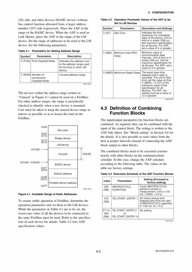
(20) side, and other devices (BASIC device) withoutbus control function allocated from a larger addressnumber (247) side respectively. Place the AXF in therange of the BASIC device. When the AXF is used asLink Master, place the AXF in the range of the LMdevice. Set the range of addresses to be used to the LMdevice. Set the following parameters.
Table 4.1 Parameters for Setting Address Range
T0401.EPS
V (FUN) First-Unpolled-Node Indicates the address next to the address range used for the host or other LM device.
V (NUN) Number-of-consecutive-Unpolled-Node
Unused address range
Symbol Parameters Description
The devices within the address range written as“Unused” in Figure 4.1 cannot be used on a Fieldbus.For other address ranges, the range is periodicallychecked to identify when a new device is mounted.Care must be taken to keep the unused device range asnarrow as possible so as to lessen the load on theFieldbus.
0xF70xF8
0xFB0xFC
0xFF
V(FUN)
V(FUN)�V(NUN)
LM device
Unused V(NUN)
BASIC device
Default address
Portable device address
F0401.EPS
Not used0x00
0x0F0x10
0x130x14
Bridge device
Figure 4.1 Available Range of Node Addresses
To ensure stable operation of Fieldbus, determine theoperation parameters and set them to the LM devices.While the parameters in Table 4.2 are to be set, theworst-case value of all the devices to be connected tothe same Fieldbus must be used. Refer to the specifica-tion of each device for details. Table 4.2 lists AXFspecification values.
Table 4.2 Operation Parameter Values of the AXF to beSet to LM Devices
Indicates the time necessary for immediate reply of the device. Unit of time is in octets (256 µs). Set maximum specification for all devices. For AXF, set a value of 4 or greater.
T0402.EPS
Symbol Parameters Description and Settings
V (ST) Slot-Time
V (MID) Minimum-Inter-PDU-Delay
Minimum value of communication data intervals. Unit of time is in octets (256 µs). Set the maximum specification for all devices. For AXF, set a value of 4 or greater.
V (MRD) Maximum-Reply-Delay The worst case time elapsed until a reply is recorded. The unit is Slot-time; set the value so that V (MRD) �V (ST) is the maximum value of the specification for all devices. For AXF, the setting must be a value of 12 or greater.
4.3 Definition of CombiningFunction Blocks
The input/output parameters for function blocks arecombined. As required, they can be combined with theinput of the control block. The setting is written to theAXF link object. See “Block setting” in Section 4.6 forthe details. It is also possible to read values from thehost at proper intervals instead of connecting the AXFblock output to other blocks.
The combined blocks need to be executed synchro-nously with other blocks on the communicationsschedule. In this case, change the AXF scheduleaccording to the following table. The values in thetable are factory-settings.
Table 4.3 Execution Schedule of the AXF Function Blocks
T0403.EPS
Index ParametersSetting (Enclosed is
factory-setting)
269(SM)
MACROCYCLE_DURATION
Cycle (MACROCYCLE) period of control or measurement. Unit is 1/32 ms. (16000 = 0.5 s)
276(SM)
FB_START_ENTRY.1 AI1 block startup time. Elapsed time from the start of MACROCYCLE specified in 1/32 ms. (0 = 0 s)
277 to289(SM)
FB_START_ENTRY.2to
FB_START_ENTRY.14
No setting
IM 01E20F02-01E4-3
4. CONFIGURATION
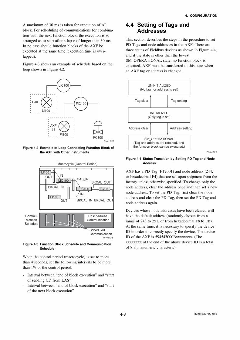
A maximum of 30 ms is taken for execution of AIblock. For scheduling of communications for combina-tion with the next function block, the execution is soarranged as to start after a lapse of longer than 30 ms.In no case should function blocks of the AXF beexecuted at the same time (execution time is over-lapped).
Figure 4.3 shows an example of schedule based on theloop shown in Figure 4.2.
F0402.EPS
LIC100
FIC100
FC100FI100
AXF#1
LI100
EJX
Figure 4.2 Example of Loop Connecting Function Block ofthe AXF with Other Instruments
LI100
LIC100
FIC100 FC100
FI100
Commu-nication
Schedule
OUT IN
OUT
CAS_INBKCAL_OUT
BKCAL_IN
BKCAL_IN
BKCAL_OUT
IN
Unscheduled Communication
Scheduled Communication
F0403.EPS
Macrocycle (Control Period)
Figure 4.3 Function Block Schedule and CommunicationSchedule
When the control period (macrocycle) is set to morethan 4 seconds, set the following intervals to be morethan 1% of the control period.
- Interval between “end of block execution” and “startof sending CD from LAS”
- Interval between “end of block execution” and “startof the next block execution”
4.4 Setting of Tags andAddresses
This section describes the steps in the procedure to setPD Tags and node addresses in the AXF. There arethree states of Fieldbus devices as shown in Figure 4.4,and if the state is other than the lowestSM_OPERATIONAL state, no function block isexecuted. AXF must be transferred to this state whenan AXF tag or address is changed.
UNINITIALIZED(No tag nor address is set)
Tag clear Tag setting
INITIALIZED(Only tag is set)
SM_OPERATIONAL(Tag and address are retained, and the function block can be executed.)
Address clear
F0404.EPS
Address setting
Figure 4.4 Status Transition by Setting PD Tag and NodeAddress
AXF has a PD Tag (FT2001) and node address (244,or hexadecimal F4) that are set upon shipment from thefactory unless otherwise specified. To change only thenode address, clear the address once and then set a newnode address. To set the PD Tag, first clear the nodeaddress and clear the PD Tag, then set the PD Tag andnode address again.
Devices whose node addresses have been cleared willhave the default address (randomly chosen from arange of 248 to 251, or from hexadecimal F8 to FB).At the same time, it is necessary to specify the deviceID in order to correctly specify the device. The deviceID of the AXF is 594543000Bxxxxxxxx. (Thexxxxxxxx at the end of the above device ID is a totalof 8 alphanumeric characters.)
IM 01E20F02-01E4-4
4. CONFIGURATION
4.5 Communication SettingTo set the communication function, it is necessary tochange the database residing in SM-VFD.
4.5.1 VCR Setting
Set VCR (Virtual Communication Relationship), whichspecifies the called party for communication andresources. AXF has 33 VCRs whose application can bechanged, except for the first VCR, which is used formanagement.
AXF has VCRs of four types:
Server(QUB) VCRA Server responds to requests from a host. Thiscommunication needs data exchange. This type ofcommunication is called QUB (Queued User-triggered Bidirectional) VCR.
Source (QUU) VCRA Source multicasts alarms or trends to otherdevices. This type of communication is called QUU(Queued User-triggered Unidirectional) VCR.
Publisher (BNU) VCRA Publisher multicasts AI block output to anotherfunction block(s). This type of communication iscalled BNU (Buffered Network-triggered Unidirec-tional) VCR.
Subscriber (BNU) VCRA Subscriber receives output of another functionblock(s) by PID block.
A Server VCR is capable to responding to requestsfrom a Client (QUB) VCR after the Client successfullyinitiates connection to the Server. A Source VCRtransmits data without established connection. A Sink(QUU) VCR on another device can receive it if theSink is configured so. A Publisher VCR transmits datawhen LAS requests so. An explicit connection isestablished from Subscriber (BNU) VCR(s) so that aSubscriber knows the format of published data.
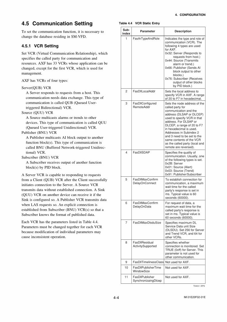
Each VCR has the parameters listed in Table 4.4.Parameters must be changed together for each VCRbecause modification of individual parameters maycause inconsistent operation.
Table 4.4 VCR Static Entry
T0404-1.EPS
Sub-index
Parameter Description
1 FasArTypeAndRole Indicates the type and role of communication (VCR). The following 4 types are used for AXF.0x32: Server (Responds to
requests from host.)0x44: Source (Transmits
alarm or trend.)0x66: Publisher (Sends AI
block output to other blocks.)
0x76: Subscriber (Receives output of other blocks by PID block.)
2 FasDllLocalAddr Sets the local address to specify VCR in AXF. A range of 20 to F7 in hexadecimal.
3 FasDllConfiguredRemoteAddr
Sets the node address of the called party for communication and the address (DLSAP or DLCEP) used to specify VCR in that address. For DLSAP or DLCEP, a range of 20 to F7 in hexadecimal is used. Addresses in Subindex 2 and 3 need to be set to the same contents of the VCR as the called party (local and remote are reversed).
4 FasDllSDAP Specifies the quality of communication. Usually, one of the following types is set.0x2B: Server0x01: Source (Alert)0x03: Source (Trend)0x91: Publisher/Subscriber
5 FasDllMaxConfirmDelayOnConnect
To establish connection for communication, a maximum wait time for the called party's response is set in ms. Typical value is 60 seconds (60000).
6 FasDllMaxConfirmDelayOnData
For request of data, a maximum wait time for the called party's response is set in ms. Typical value is 60 seconds (60000).
7 FasDllMaxDlsduSize Specifies maximum DL Service Data unit Size (DLSDU). Set 256 for Server and Trend VCR, and 64 for other VCRs.
8 FasDllResidualActivitySupported
Specifies whether connection is monitored. Set TRUE (0xff) for Server. This parameter is not used for other communication.
9 FasDllTimelinessClass Not used for AXF.
10 FasDllPublisherTimeWindowSize
Not used for AXF.
11 FasDllPublisherSynchronizaingDlcep
Not used for AXF.
IM 01E20F02-01E4-5
4. CONFIGURATION
T0404-2.EPS
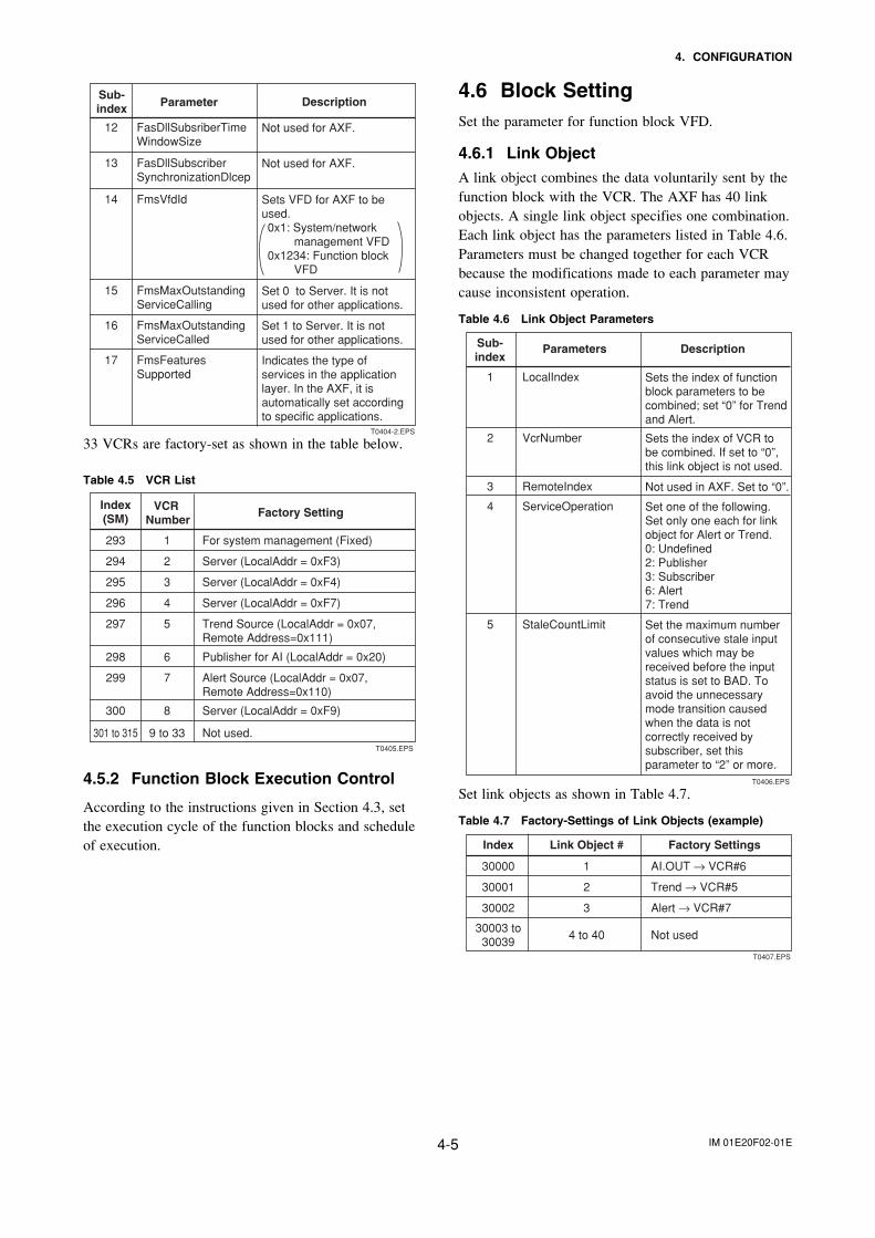
13 FasDllSubscriberSynchronizationDlcep
Not used for AXF.
14 FmsVfdId Sets VFD for AXF to be used. 0x1: System/network
management VFD0x1234: Function block
VFD
15 FmsMaxOutstandingServiceCalling
Set 0 to Server. It is not used for other applications.
16 FmsMaxOutstandingServiceCalled
Set 1 to Server. It is not used for other applications.
17 FmsFeaturesSupported
Indicates the type of services in the application layer. In the AXF, it is automatically set according to specific applications.
Sub-index Parameter Description
12 FasDllSubsriberTimeWindowSize
Not used for AXF.
33 VCRs are factory-set as shown in the table below.
Table 4.5 VCR List
Index(SM)
VCR Number
Factory Setting
293 For system management (Fixed)1
294 Server (LocalAddr = 0xF3)2
295 Server (LocalAddr = 0xF4)3
296 Server (LocalAddr = 0xF7)4
297 Trend Source (LocalAddr = 0x07, Remote Address=0x111)
5
298 Publisher for AI (LocalAddr = 0x20)6
299 Alert Source (LocalAddr = 0x07, Remote Address=0x110)
7
300 Server (LocalAddr = 0xF9)8
301 to 315 Not used.9 to 33T0405.EPS
4.5.2 Function Block Execution Control
According to the instructions given in Section 4.3, setthe execution cycle of the function blocks and scheduleof execution.
4.6 Block SettingSet the parameter for function block VFD.
4.6.1 Link ObjectA link object combines the data voluntarily sent by thefunction block with the VCR. The AXF has 40 linkobjects. A single link object specifies one combination.Each link object has the parameters listed in Table 4.6.Parameters must be changed together for each VCRbecause the modifications made to each parameter maycause inconsistent operation.
Table 4.6 Link Object Parameters
T0406.EPS
Sub-index
Parameters Description
1 LocalIndex Sets the index of function block parameters to be combined; set “0” for Trend and Alert.
2 VcrNumber Sets the index of VCR to be combined. If set to “0”, this link object is not used.
3 RemoteIndex Not used in AXF. Set to “0”.
5 StaleCountLimit Set the maximum number of consecutive stale input values which may be received before the input status is set to BAD. To avoid the unnecessary mode transition caused when the data is not correctly received by subscriber, set this parameter to “2” or more.
4 ServiceOperation Set one of the following. Set only one each for link object for Alert or Trend.0: Undefined2: Publisher3: Subscriber6: Alert7: Trend
Set link objects as shown in Table 4.7.
Table 4.7 Factory-Settings of Link Objects (example)
T0407.EPS
Index Link Object # Factory Settings
30000 AI.OUT → VCR#61
30001 Trend → VCR#52
30002 Alert → VCR#73
30003 to30039
Not used4 to 40
IM 01E20F02-01E4-6
4. CONFIGURATION
F0405.EPS
SMIB(System Management Information Base)
NMIB(Network Management Information Base)
AI OUT
FBODAlert
Trend
VCR
DLSAPDLCEP
Fieldbus Cable
AX
F
0xF8 0xF3 0xF4 0xF7 0xF9 0x20 0x21 0x07
#1 #2#3#4
Resourceblock
Transducerblock
Host 1 Host 2 Device 1 Device 2
Linkobject
#1 #2 #3 #4 #5#6 #7#8 #9
DI2 OUT
DI1 OUT
Figure 4.5 Example of Default Configuration
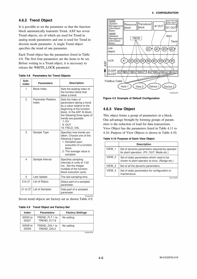
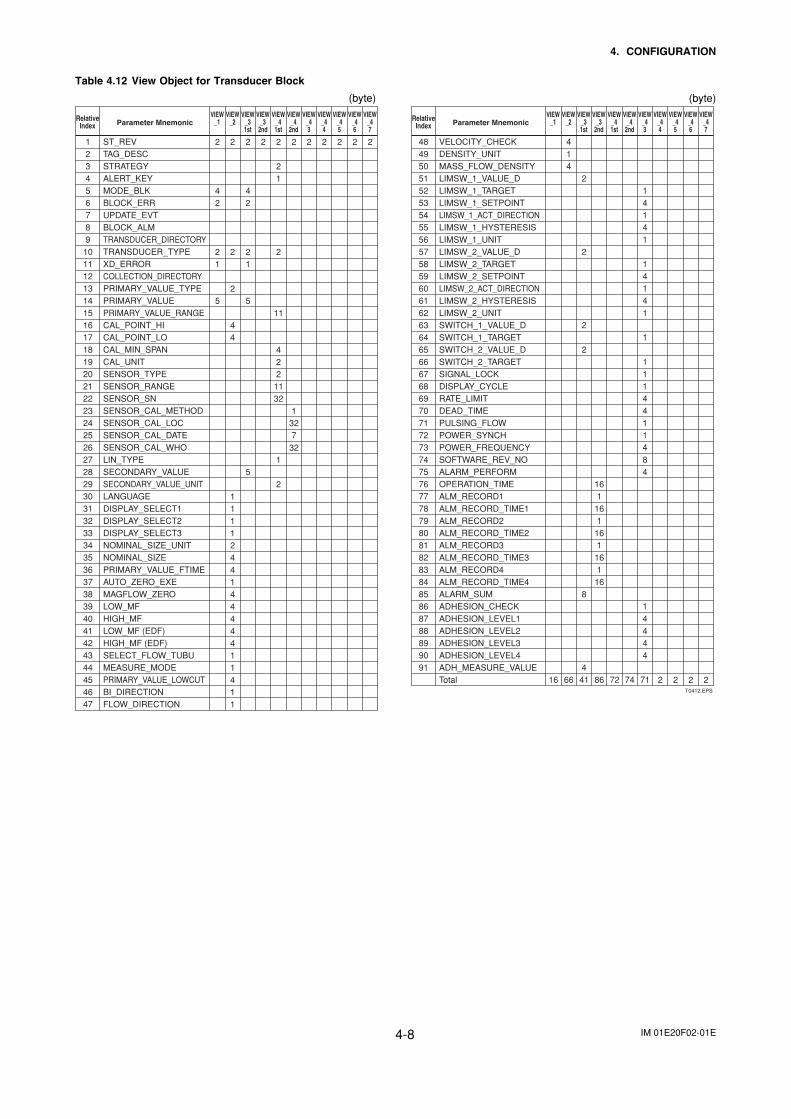
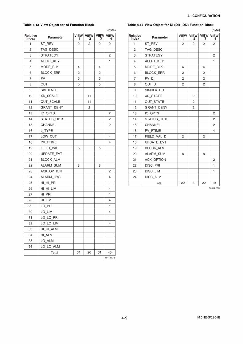
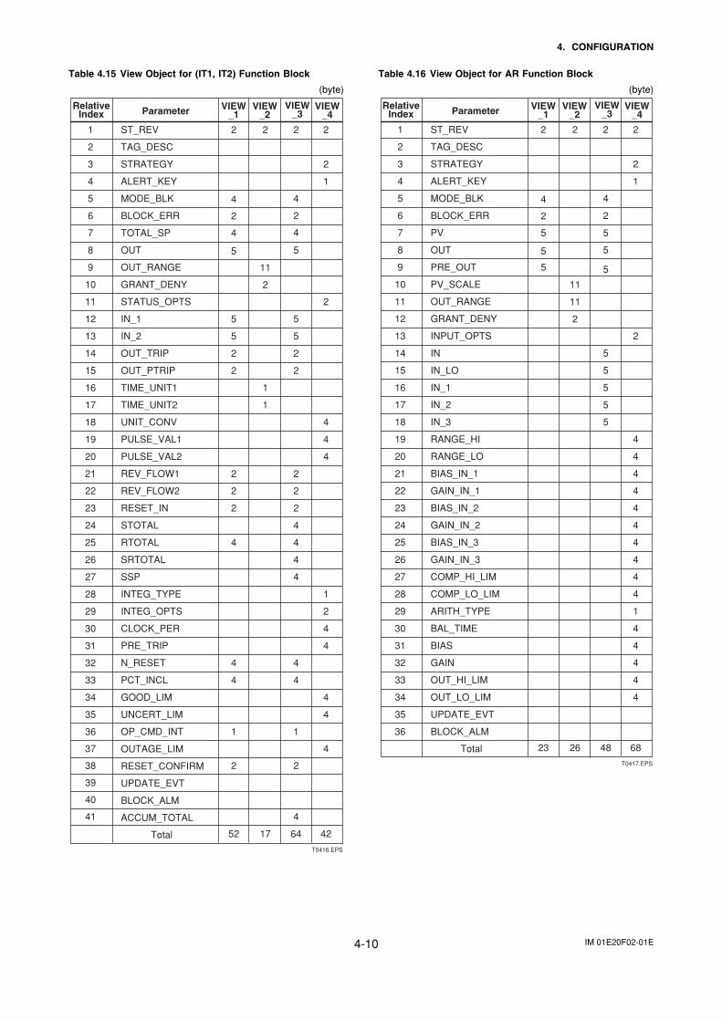
4.6.3 View Object
This object forms a group of parameters in a block.One advantage brought by forming groups of param-eters is the reduction of load for data transactions.View Object has the parameters listed in Table 4.11 to4.16. Purpose of View Objects is shown in Table 4.10.
Table 4.10 Purpose of Each View Object
VIEW_1
VIEW_2
VIEW_3
VIEW_4
Set of all the dynamic parameters.
Description
Set of dynamic parameters required by operator for plant operation. (PV, OUT, Mode etc.)
Set of static parameters which need to be shown to plant operator at once. (Range etc.)
Set of static parameters for configuration or maintenance.
T0410.EPS
4.6.2 Trend Object
It is possible to set the parameter so that the functionblock automatically transmits Trend. AXF has sevenTrend objects, six of which are used for Trend inanalog mode parameters and one is used for Trend indiscrete mode parameter. A single Trend objectspecifies the trend of one parameter.
Each Trend object has the parameters listed in Table4.8. The first four parameters are the items to be set.Before writing to a Trend object, it is necessary torelease the WRITE_LOCK parameter.
Table 4.8 Parameters for Trend Objects
T0408.EPS
Sub-index Parameters Description
1 Block Index Sets the leading index of the function block that takes a trend.
2 Parameter Relative Index
Sets the index of parameters taking a trend by a value relative to the beginning of the function block. In the AXF AI block, the following three types of trends are possible. 7: PV 8: OUT19: FIELD_VAL
3 Sample Type Specifies how trends are taken. Choose one of the following 2 types:1: Sampled upon
execution of a function block.
2: The average value is sampled.
4 Sample Interval Specifies sampling intervals in units of 1/32 ms. Set the integer multiple of the function block execution cycle.
5 Last Update The last sampling time.
6 to 21 List of Status Status part of a sampled parameter.
21 to 37 List of Samples Data part of a sampled parameter.
Seven trend objects are factory-set as shown Table 4.9.
Table 4.9 Trend Object are Factory-Set
T0409.EPS
Index Parameters Factory Settings
32000 to32007
No settingTREND_FLT.1 toTREND_FLT.8
32008 to32009
No settingTREND_DIS.1 toTREND_DIS.2
IM 01E20F02-01E4-7
4. CONFIGURATION
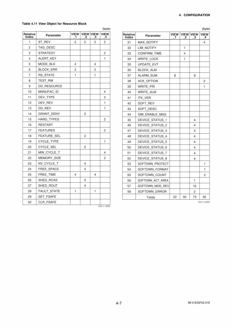
Table 4.11 View Object for Resource Block
(byte)
T0411-1.EPS
1 ST_REV 2
2 TAG_DESC
3 STRATEGY
4 ALERT_KEY
5 MODE_BLK 4
6 BLOCK_ERR 2
7 RS_STATE
8 TEST_RW
9 DD_RESOURCE
10 MANUFAC_ID
2 2
4
2
1 1
2
2
1
4
VIEW_1
VIEW_2
VIEW_3
VIEW_4
RelativeIndex Parameter
11 DEV_TYPE
12 DEV_REV
13 DD_REV
14 GRANT_DENY
15 HARD_TYPES
16 RESTART
17 FEATURES
18 FEATURE_SEL
19 CYCLE_TYPE
20 CYCLE_SEL
21 MIN_CYCLE_T
22 MEMORY_SIZE
23 NV_CYCLE_T
24 FREE_SPACE
425 FREE_TIME
26 SHED_RCAS
27 SHED_ROUT
128 FAULT_STATE
29 SET_FSAFE
30 CLR_FSAFE
2
2
2
4
4
4
4
4
1
2
1
1
2
2
1
4
2
(byte)
T0411-2.EPS
22 30 73 35
4
4
4
4
4
4
4
1
1
2
1
16
2
46 DEVICE_STATUS_2
47 DEVICE_STATUS_3
48 DEVICE_STATUS_4
49 DEVICE_STATUS_5
50 DEVICE_STATUS_6
51 DEVICE_STATUS_7
52
53
54
55
56
57
58
DEVICE_STATUS_8
Totals
SOFTDWN_PROTECT
SOFTDWN_ERROR
SOFTDWN_MOD_REV
SOFTDWN_ACT_AREA
SOFTDWN_COUNT
SOFTDWN_FORMAT
31 MAX_NOTIFY
32 LIM_NOTIFY
33 CONFIRM_TIME
34 WRITE_LOCK
35 UPDATE_EVT
36 BLOCK_ALM
837 ALARM_SUM
1
4
1
8
4
38 ACK_OPTION 2
39 WRITE_PRI 1
4
40 WRITE_ALM
41 ITK_VER
42 SOFT_REV
43 SOFT_DESC
44 SIM_ENABLE_MSG
45 DEVICE_STATUS_1
VIEW_1
VIEW_2
VIEW_3
VIEW_4
RelativeIndex Parameter
IM 01E20F02-01E4-8
4. CONFIGURATION
Table 4.12 View Object for Transducer Block
(byte)
T0412.EPS
ST_REVTAG_DESCSTRATEGYALERT_KEYMODE_BLKBLOCK_ERRUPDATE_EVTBLOCK_ALMTRANSDUCER_DIRECTORYTRANSDUCER_TYPEXD_ERRORCOLLECTION_DIRECTORYPRIMARY_VALUE_TYPEPRIMARY_VALUEPRIMARY_VALUE_RANGECAL_POINT_HICAL_POINT_LOCAL_MIN_SPANCAL_UNITSENSOR_TYPESENSOR_RANGESENSOR_SNSENSOR_CAL_METHODSENSOR_CAL_LOCSENSOR_CAL_DATESENSOR_CAL_WHOLIN_TYPESECONDARY_VALUESECONDARY_VALUE_UNITLANGUAGEDISPLAY_SELECT1DISPLAY_SELECT2DISPLAY_SELECT3NOMINAL_SIZE_UNITNOMINAL_SIZEPRIMARY_VALUE_FTIMEAUTO_ZERO_EXEMAGFLOW_ZEROLOW_MFHIGH_MFLOW_MF (EDF)HIGH_MF (EDF)SELECT_FLOW_TUBUMEASURE_MODEPRIMARY_VALUE_LOWCUTBI_DIRECTIONFLOW_DIRECTION
VIEW_1
VIEW_2
VIEW_31st
VIEW_3
2nd
VIEW_41st
VIEW_4
2nd
VIEW_43
RelativeIndex Parameter Mnemonic
123456789
1011121314151617181920212223242526272829303132333435363738394041424344454647
2
4 2
2 1
5
2
2
2
4 4
1 1 1 1 2 4 4 1 4 4 4 4 4 1 1 411
2
4 2
2 1
5
5
2 2
2 1
2
11
4 2 2 11 32
1
2
2
1 32 7 32
2 2 2 2 2 VELOCITY_CHECKDENSITY_UNITMASS_FLOW_DENSITYLIMSW_1_VALUE_DLIMSW_1_TARGETLIMSW_1_SETPOINTLIMSW_1_ACT_DIRECTIONLIMSW_1_HYSTERESISLIMSW_1_UNITLIMSW_2_VALUE_DLIMSW_2_TARGETLIMSW_2_SETPOINTLIMSW_2_ACT_DIRECTIONLIMSW_2_HYSTERESISLIMSW_2_UNITSWITCH_1_VALUE_DSWITCH_1_TARGETSWITCH_2_VALUE_DSWITCH_2_TARGETSIGNAL_LOCKDISPLAY_CYCLERATE_LIMITDEAD_TIMEPULSING_FLOWPOWER_SYNCHPOWER_FREQUENCYSOFTWARE_REV_NOALARM_PERFORMOPERATION_TIMEALM_RECORD1ALM_RECORD_TIME1ALM_RECORD2ALM_RECORD_TIME2ALM_RECORD3ALM_RECORD_TIME3ALM_RECORD4ALM_RECORD_TIME4ALARM_SUMADHESION_CHECKADHESION_LEVEL1ADHESION_LEVEL2ADHESION_LEVEL3ADHESION_LEVEL4ADH_MEASURE_VALUETotal
4849505152535455565758596061626364656667686970717273747576777879808182838485868788899091
16
414
66
2
2
2
2
8
441 72
16 1 16116 1 16 116
86 74
14 1 4 1
1 4141
1
111 4 4 1 1 4 8 4
14444
71
VIEW_44
2
VIEW_45
2
VIEW_46
2
VIEW_47
VIEW_1
VIEW_2
VIEW_31st
VIEW_3
2nd
VIEW_41st
VIEW_4
2nd
VIEW_43
RelativeIndex Parameter Mnemonic
VIEW_44
VIEW_45
VIEW_46
VIEW_47
2
(byte)
IM 01E20F02-01E4-9
4. CONFIGURATION
Table 4.13 View Object for AI Function Block
(byte)
T0413.EPS
1 ST_REV 2
2 TAG_DESC
3 STRATEGY
4 ALERT_KEY
5 MODE_BLK 4
6 BLOCK_ERR 2
7 PV
8 OUT 5
9 SIMULATE
10 XD_SCALE
11 OUT_SCALE
12 GRANT_DENY
13 IO_OPTS
14 STATUS_OPTS
15 CHANNEL
16 L_TYPE
17 LOW_CUT
18 PV_FTIME
519 FIELD_VAL
20 UPDATE_EVT
21 BLOCK_ALM
822 ALARM_SUM
23 ACK_OPTION
24 ALARM_HYS
25 HI_HI_PRI
26 HI_HI_LIM
27 HI_PRI
28 HI_LIM
29 LO_PRI
30 LO_LIM
31 LO_LO_PRI
32 LO_LO_LIM
33 HI_HI_ALM
34 HI_ALM
35 LO_ALM
36 LO_LO_ALM
2
11
11
2
2
4
2
5 5
5
5
8
2
2
1
31 26 31 46
2
2
2
1
4
4
2
4
1
4
1
4
1
4
1
4
VIEW_1
VIEW_2
VIEW_3
VIEW_4
RelativeIndex Parameter
Total
Table 4.14 View Object for DI (DI1, DI2) Function Block
(byte)
T0414.EPS
1 ST_REV 2
2 TAG_DESC
3 STRATEGY
4 ALERT_KEY
5 MODE_BLK 4
6 BLOCK_ERR 2
7 PV_D
8 OUT_D 2
9 SIMULATE_D
10 XD_STATE
11 OUT_STATE
12 GRANT_DENY
13 IO_OPTS
14 STATUS_OPTS
15 CHANNEL
16 PV_FTIME
217 FIELD_VAL_D
18 UPDATE_EVT
19 BLOCK_ALM
820 ALARM_SUM
21 ACK_OPTION
22 DISC_PRI
23 DISC_LIM
24 DISC_ALM
2
2
2
2
2
4
2
2 2
2
2
8
2
2
1
22 8 22 19
2
2
2
4
2
1
1
VIEW_1
VIEW_2
VIEW_3
VIEW_4
RelativeIndex Parameter
Total
IM 01E20F02-01E4-10
4. CONFIGURATION
Table 4.15 View Object for (IT1, IT2) Function Block
(byte)
T0416.EPS
1 ST_REV
TAG_DESC
STRATEGY
ALERT_KEY
MODE_BLK
BLOCK_ERR
TOTAL_SP
OUT
OUT_RANGE
GRANT_DENY
STATUS_OPTS
IN_1
IN_2
OUT_TRIP
OUT_PTRIP
TIME_UNIT1
TIME_UNIT2
UNIT_CONV
PULSE_VAL1
PULSE_VAL2
REV_FLOW1
REV_FLOW2
RESET_IN
STOTAL
RTOTAL
SRTOTAL
SSP
INTEG_TYPE
INTEG_OPTS
CLOCK_PER
PRE_TRIP
N_RESET
PCT_INCL
GOOD_LIM
UNCERT_LIM
OP_CMD_INT
OUTAGE_LIM
RESET_CONFIRM
UPDATE_EVT
BLOCK_ALM
ACCUM_TOTAL
2
2
2
3
4
5
6
7
8
9
10
11
5
5
12
513
214
215
16
17
18
19
20
221
222
223
24
4
4
25
26
27
28
29
30
31
432
433
34
35
136
2
11
2
1
1
2
4
4
2
4
5
5
5
2
2
2
2
2
4
4
4
4
4
4
1
2
2
1
52 17 64 42
2
4
4
4
1
2
4
4
4
4
37 4
238 2
39
40
41 4
VIEW_1
VIEW_2
VIEW_3
VIEW_4
RelativeIndex Parameter
Total
Table 4.16 View Object for AR Function Block
(byte)
2
5
4
T0417.EPS
1 ST_REV
TAG_DESC
STRATEGY
ALERT_KEY
MODE_BLK
BLOCK_ERR
PV
OUT
PRE_OUT
PV_SCALE
OUT_RANGE
GRANT_DENY
INPUT_OPTS
IN
IN_LO
IN_1
IN_2
IN_3
RANGE_HI
RANGE_LO
BIAS_IN_1
GAIN_IN_1
BIAS_IN_2
GAIN_IN_2
BIAS_IN_3
GAIN_IN_3
COMP_HI_LIM
COMP_LO_LIM
ARITH_TYPE
BAL_TIME
BIAS
GAIN
OUT_HI_LIM
OUT_LO_LIM
UPDATE_EVT
BLOCK_ALM
2
2
3
4
5
6
7
8
9
10
11
12
13
14
15
16
17
18
19
20
21
22
23
24
25
26
27
28
29
30
31
32
33
34
35
36
2
11
11
2
2
4
2
5
5
5
5
5
5
5
5
5
5
2
2
1
23 26 48 68
2
4
4
4
4
4
4
4
4
4
4
1
4
4
4
4
4
VIEW_1
VIEW_2
VIEW_3
VIEW_4
RelativeIndex Parameter
Total

IM 01E20F02-01E4-11
4. CONFIGURATION
Table 4.17 Indexes of View for Each Block
T0415.EPS
VIEW_3VIEW_2VIEW_1 VIEW_4
40600
40612
40602
40610
40400 40402
402024020140200
40401
40601
40611
40803408024080140800
41603416024160141600
41613416124161141610
41753417524175141750
40613
40203
40403
40603
PID Function Block
IT1 Function Block
IT2 Function Block
AR Function Block
DI2 Function Block
AI Function Block
DI1 Function Block
Transducer Block
401024010140100 40103Resourse Block
4.6.4 Function Block Parameters
Function block parameters can be read from the host orcan be set. For a list of the parameters of Resourceblock, Transducer block, AI block and DI block, referto “8. PARAMETER LISTS”. For other functionblocks, refer to Appendix.
IM 01E20F02-01E5-1
5. EXPLANATION OF BASIC ITEMS
5. EXPLANATION OF BASIC ITEMS
5.1 OutlineThis chapter describes basic TR (Transducer block),AI, and DI function block parameter setting, displaysof the integral indicator. Refer to Appendixes otherfunction blocks and LM function.
This chapter contains information on how to adapt thefunction and performance of the ADMAG AXF to suitspecific applications. Because two or more devices areconnected to FOUNDATION Fieldbus, settings includingthe requirements of all devices need to be determined.Practically, the following steps must be taken.
The following section describes each step of theprocedure in the order given. Using a dedicatedconfiguration tool allows the procedure to be signifi-cantly simplified. This section describes the procedurewhich has relatively simple functions.
5.2 Setting and Changing Param-eters for the Whole Process
IMPORTANT
Do not turn off the power immediately aftersetting. When the parameters are saved to theEEPROM, the redundant processing is executedfor an improvement of reliability. If the power isturned off within 60 seconds after setting ismade, the modified parameters are not savedand the setting may return to the original values.
Block modeMany parameters require a change of the block modeof the function block to O/S (Out of Service) whentheir data is changed. To change the block mode of thefunction block, its MODE_BLK needs to be changed.The MODE_BLK is comprised of four sub-parametersbelow.
(1) Target (Target mode):Sets the operating condition of the block.
(2) Actual (Actual mode):Indicates the current operating condition.
(3) Permit (Permitted mode):Indicates the operating condition that the blockis allowed to take.
(4) Normal (Normal mode):Indicates the operating condition that the blockwill usually take.
IM 01E20F02-01E5-2
5. EXPLANATION OF BASIC ITEMS
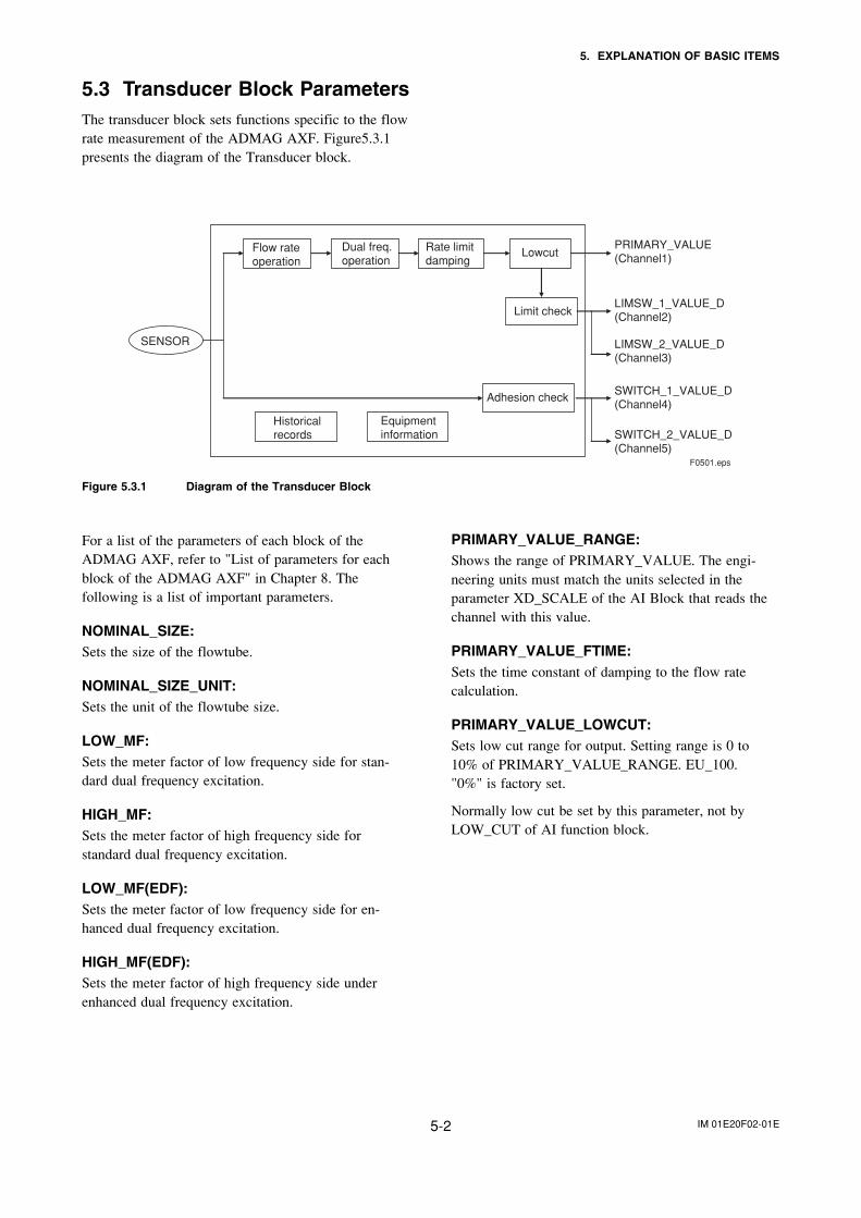
5.3 Transducer Block ParametersThe transducer block sets functions specific to the flowrate measurement of the ADMAG AXF. Figure5.3.1presents the diagram of the Transducer block.
PRIMARY_VALUE_RANGE:Shows the range of PRIMARY_VALUE. The engi-neering units must match the units selected in theparameter XD_SCALE of the AI Block that reads thechannel with this value.
PRIMARY_VALUE_FTIME:Sets the time constant of damping to the flow ratecalculation.
PRIMARY_VALUE_LOWCUT:Sets low cut range for output. Setting range is 0 to10% of PRIMARY_VALUE_RANGE. EU_100."0%" is factory set.
Normally low cut be set by this parameter, not byLOW_CUT of AI function block.
Equipment information
SENSOR
Flow rateoperation
Dual freq.operation
Rate limitdamping
Lowcut
Limit check
Adhesion check
F0501.eps
Historical records
PRIMARY_VALUE(Channel1)
LIMSW_1_VALUE_D(Channel2)
LIMSW_2_VALUE_D(Channel3)
SWITCH_1_VALUE_D(Channel4)
SWITCH_2_VALUE_D(Channel5)
Figure 5.3.1 Diagram of the Transducer Block
For a list of the parameters of each block of theADMAG AXF, refer to "List of parameters for eachblock of the ADMAG AXF" in Chapter 8. Thefollowing is a list of important parameters.
NOMINAL_SIZE:Sets the size of the flowtube.
NOMINAL_SIZE_UNIT:Sets the unit of the flowtube size.
LOW_MF:Sets the meter factor of low frequency side for stan-dard dual frequency excitation.
HIGH_MF:Sets the meter factor of high frequency side forstandard dual frequency excitation.
LOW_MF(EDF):Sets the meter factor of low frequency side for en-hanced dual frequency excitation.
HIGH_MF(EDF):Sets the meter factor of high frequency side underenhanced dual frequency excitation.

IM 01E20F02-01E5-3
5. EXPLANATION OF BASIC ITEMS
DISPLAY_SELECT1, 2, 3:Table 5.3.1 DISPLAY SELECT
DISPLAY_SELECT 1 DISPLAY_SELECT 2 DISPLAY_SELECT 3
The display content for the displayunit's first line.
The display content for the display unit'ssecond line.
The display content for the display unit's third line.
1:Flow Rate(%) 1:Off 1:Off
2:Flow Rate 2:Flow Rate(%) 2:Flow Rate(%)
3:Integrator1 Out 3:Flow Rate 3:Flow Rate
4:Integrator2 Out 4:Flow Rate(Bar) 4:Flow Rate(Bar)
5:Arithmetic Out 5:Integrator1 Out 5:Integrator1 Out
6:Integrator2 Out 6:Integrator2 Out
The factory default setting is 2. 7:Arithmetic Out 7:Arithmetic Out
8:PD Tag 8:PD Tag
9:Adhesion Check 9:Adhesion Check
10:Communication 10:Communication
The factory default setting is 1. The factory default setting is
T0501.eps
1.
DISPLAY_CYCLE:Sets the cycle of LCD display. The factory defaultsetting of the display cycle is 2: 400ms. The validrange can be selected from below;
1: 200ms2: 400ms3: 1s4: 2s5: 4s6: 8s
If the low temperature environment makes it difficultto view the display, it is recommended that you set alonger display cycle.
PRIMARY_VALUE_TYPE:Indicates the measuring value type used inPRIMARY_VALUE. Valid range are as follows;
100: mass flow101: volumetric flow102: average mass flow103: average volumetric flow65535: other
Factory default is 101: volumetric flow.
ALARM_PERFORM(1) Overview
This parameter masks Alarm/Warning. Bysetting "0" to each bit, correspondingAlarm/Warning are cleared. When masked thecorresponding bit of DEVICE_STATUSbecomes OFF and no alarm is displayed onLCD, and also becomes out of scope ofPrimary value status, ED_ERROR setting.
(2) Bit mapping (0 :MASK, 1 :NON MASK)bitbit categorizecategorize AlarmAlarm
0 Process 30:Sig Overflow1 Alarms 31: Empty Pipe2
Warning33:Adhesion Alm
34
80:Adhesion Wng82:Auto Zero Wng
defaltdefalt
11001
5 85:Flow Vel Over 16 ~ 15 Not used in AXF 0
23 ~ 31 Not used in AXF 0
16 AI 42:AI FB O/S Mode110:AI Lo Lo Alm111:AI Hi Hi Alm130:AI Non-Schedule141:AI Sim. Enabled150:AI FB Man Mode
1
17 IT1 43:IT1 FB O/S Mode131:IT1 Non-Schedule151:IT1 FB Man Mode120:IT1 Low Clock Per
0
18 IT2 44:IT2 FB O/S Mode132:IT2 Non-Schedule152:IT2 FB Man Mode121:IT2 Low Clock Per
0
19 DI1 45:DI1 FB O/S Mode133:DI1 Non-Schedule142:DI1 Sim. Enabled153:DI1 FB Man Mode
0
20 DI2 46:DI2 FB O/S Mode134:DI2 Non-Schedule143:DI2 Sim. Enabled154:DI2 FB Man Mode
0
21 AR 47:AR FB O/S Mode135:AR Non-Schedule155:AR FB Man Mode122:AR Range Set Err
0
22 PID 42:PID FB O/S Mode112:PID Lo Lo Alm113:PID Hi Hi Alm136:PID Non-Schedule156:PID FB Man Mode160:PID FB Bypass Mode
0
T0502.eps
IM 01E20F02-01E5-4
5. EXPLANATION OF BASIC ITEMS
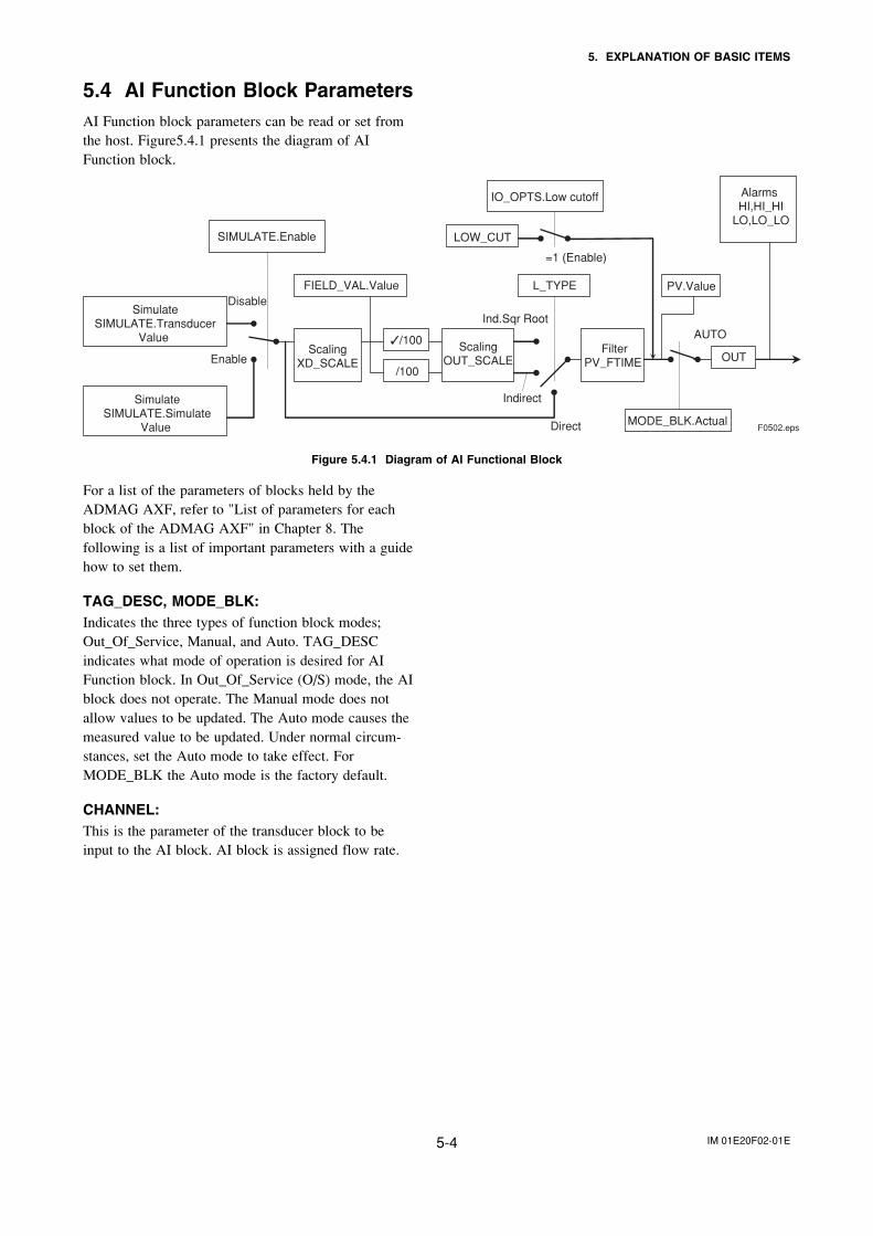
5.4 AI Function Block ParametersAI Function block parameters can be read or set fromthe host. Figure5.4.1 presents the diagram of AIFunction block.
MODE_BLK.Actual
OUT
AUTO
Direct F0502.eps
Indirect
FilterPV_FTIME
Alarms HI,HI_HI
LO,LO_LO
PV.Value
=1 (Enable)
IO_OPTS.Low cutoff
LOW_CUT
L_TYPE
Ind.Sqr Root
ScalingOUT_SCALE
SIMULATE.Enable
FIELD_VAL.Value
ScalingXD_SCALE
/100
✓/100
Disable
Enable
SimulateSIMULATE.Transducer
Value
SimulateSIMULATE.Simulate
Value
Figure 5.4.1 Diagram of AI Functional Block
For a list of the parameters of blocks held by theADMAG AXF, refer to "List of parameters for eachblock of the ADMAG AXF" in Chapter 8. Thefollowing is a list of important parameters with a guidehow to set them.
TAG_DESC, MODE_BLK:Indicates the three types of function block modes;Out_Of_Service, Manual, and Auto. TAG_DESCindicates what mode of operation is desired for AIFunction block. In Out_Of_Service (O/S) mode, the AIblock does not operate. The Manual mode does notallow values to be updated. The Auto mode causes themeasured value to be updated. Under normal circum-stances, set the Auto mode to take effect. ForMODE_BLK the Auto mode is the factory default.
CHANNEL:This is the parameter of the transducer block to beinput to the AI block. AI block is assigned flow rate.
IM 01E20F02-01E5-5
5. EXPLANATION OF BASIC ITEMS
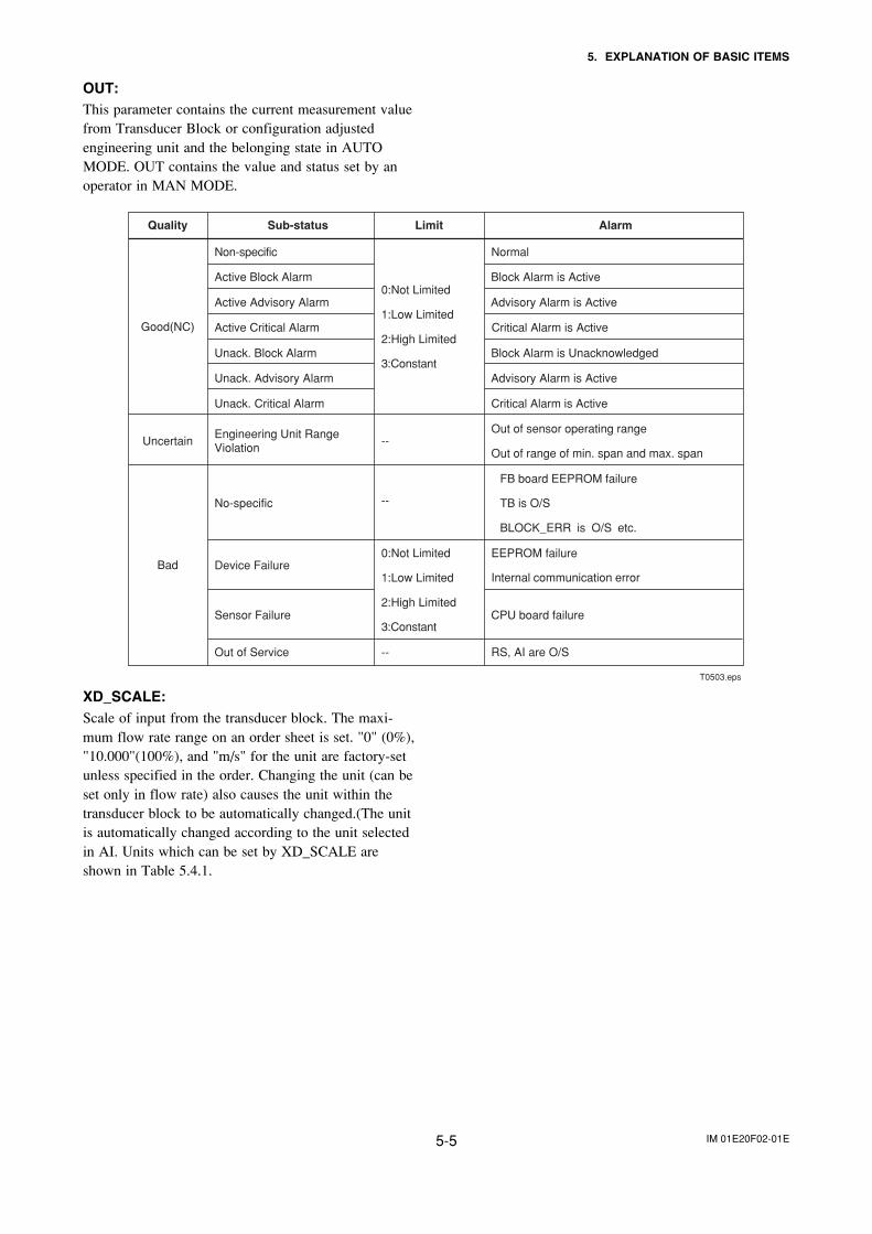
OUT:This parameter contains the current measurement valuefrom Transducer Block or configuration adjustedengineering unit and the belonging state in AUTOMODE. OUT contains the value and status set by anoperator in MAN MODE.
Quality Sub-status Limit Alarm
Non-specific Normal
Active Block Alarm Block Alarm is Active
Active Advisory Alarm Advisory Alarm is Active
Active Critical Alarm Critical Alarm is Active
Unack. Block Alarm Block Alarm is Unacknowledged
Unack. Advisory Alarm Advisory Alarm is Active
Good(NC)
Unack. Critical Alarm
0:Not Limited
1:Low Limited
2:High Limited
3:Constant
0:Not Limited
1:Low Limited
2:High Limited
3:Constant
Critical Alarm is Active
UncertainEngineering Unit Range Violation
--
--
Out of sensor operating range
Out of range of min. span and max. span
No-specific
FB board EEPROM failure
TB is O/S
BLOCK_ERR is O/S etc.
Device FailureEEPROM failure
Internal communication error
Sensor Failure CPU board failure
Bad
Out of Service -- RS, AI are O/S
T0503.eps
XD_SCALE:Scale of input from the transducer block. The maxi-mum flow rate range on an order sheet is set. "0" (0%),"10.000"(100%), and "m/s" for the unit are factory-setunless specified in the order. Changing the unit (can beset only in flow rate) also causes the unit within thetransducer block to be automatically changed.(The unitis automatically changed according to the unit selectedin AI. Units which can be set by XD_SCALE areshown in Table 5.4.1.
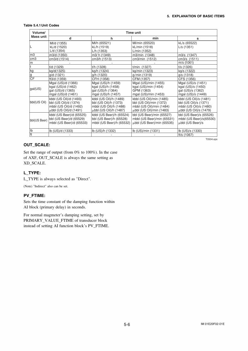
IM 01E20F02-01E5-6
5. EXPLANATION OF BASIC ITEMS
Table 5.4.1 Unit Codes
d
LMl/h (65521)kL/h (1519)L/h (1353)
Ml/min (65520)kL/min (1518)L/min (1352)
kL/s (65522)L/s (1351)
m3 m3/d (1350) m3/ h (1349) m3/min (1348) m3/s (1347)cm3 cm3/d (1514) cm3/h (1513) cm3/min (1512) cm3/s (1511)m - - - m/s (1061)t t/d (1329) t/h (1328) t/min (1327) t/s (1326)kg kg/d(1325) kg/h (1324) kg/min (1323) kg/s (1322)g g/d (1321) g/h (1320) g/min (1319) g/s (1318)CF ft3/d (1359) CFH (1358) CFM (1357) CFS (1356)
Mgal (US)/d (1366)kgal (US)/d (1462)gal (US)/d (1365)mgal (US)/d (1461)
Mgal (US)/h (1459)kgal (US)/h (1458)gal (US)/h (1364)mgal (US)/h (1457)
Mgal (US)/min (1455)kgal (US)/min (1454)GPM (1363)mgal (US)/min (1453)
Mgal (US)/s (1451)kgal (US)/s (1450)gal (US)/s (1362)mgal (US)/s (1449)
kbbl (US Oil)/d (1493)bbl (US Oil)/d (1374)mbbl (US Oil)/d (1492)�bbl (US Oil)/d (1491)
kbbl (US Oil)/h (1489)bbl (US Oil)/h (1373)mbbl (US Oil)/h (1488)�bbl (US Oil)/h (1487)
kbbl (US Oil)/min (1485)bbl (US Oil)/min (1372)mbbl (US Oil)/min (1484)�bbl (US Oil)/min (1483)
kbbl (US Oil)/s (1481)bbl (US Oil)/s (1371)mbbl (US Oil)/s (1480)�bbl (US Oil)/s (1479)
kbbl (US Beer)/d (65525)bbl (US Beer)/d (65529)mbbl (US Beer)/d (65533)
kbbl (US Beer)/h (65524)bbl (US Beer)/h (65528)mbbl (US Beer)/h (65532)
bbl (US Beer)/min (65527)mbbl (US Beer)/min (65531)�bbl (US Beer)/min (65535)
bbl (US Beer)/s (65526)mbbl (US Beer)/s(65530)�bbl (US Beer)/s
lb lb (US)/d (1333) lb (US)/h (1332) lb (US)/min (1331) lb (US)/s (1330)ft - - - ft/s (1067)
Volume/Mass unit
Time unit
minh s
gal(US)
bbl(US Oil)
bbl(US Beer)
Ml/d (1355)kL/d (1520)L/d (1354)
T0504.eps
OUT_SCALE:
Set the range of output (from 0% to 100%). In the caseof AXF, OUT_SCALE is always the same setting asXD_SCALE.
L_TYPE:L_TYPE is always selected as "Direct".
(Note) "Indirect" also can be set.
PV_FTIME:Sets the time constant of the damping function withinAI block (primary delay) in seconds.
For normal magmeter’s damping setting, set byPRIMARY_VALUE_FTIME of transducer blockinstead of setting AI function block’s PV_FTIME.
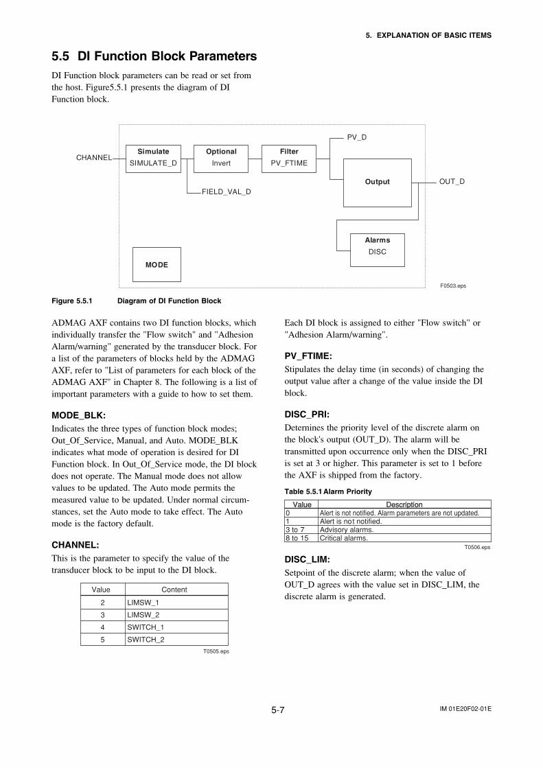
IM 01E20F02-01E5-7
5. EXPLANATION OF BASIC ITEMS
5.5 DI Function Block ParametersDI Function block parameters can be read or set fromthe host. Figure5.5.1 presents the diagram of DIFunction block.
FIELD_VAL_DOUT_D
CHANNEL
PV_D
Alarms
DISC
Optional
Invert
Filter
PV_FTIME
Simulate
SIMULATE_D
MODE
Output
F0503.eps
Figure 5.5.1 Diagram of DI Function Block
ADMAG AXF contains two DI function blocks, whichindividually transfer the "Flow switch" and "AdhesionAlarm/warning" generated by the transducer block. Fora list of the parameters of blocks held by the ADMAGAXF, refer to "List of parameters for each block of theADMAG AXF" in Chapter 8. The following is a list ofimportant parameters with a guide to how to set them.
MODE_BLK:Indicates the three types of function block modes;Out_Of_Service, Manual, and Auto. MODE_BLKindicates what mode of operation is desired for DIFunction block. In Out_Of_Service mode, the DI blockdoes not operate. The Manual mode does not allowvalues to be updated. The Auto mode permits themeasured value to be updated. Under normal circum-stances, set the Auto mode to take effect. The Automode is the factory default.
CHANNEL:This is the parameter to specify the value of thetransducer block to be input to the DI block.
Value Content
2 LIMSW_1
3 LIMSW_2
4 SWITCH_1
5 SWITCH_2
T0505.eps
Each DI block is assigned to either "Flow switch" or"Adhesion Alarm/warning".
PV_FTIME:Stipulates the delay time (in seconds) of changing theoutput value after a change of the value inside the DIblock.
DISC_PRI:Deternines the priority level of the discrete alarm onthe block's output (OUT_D). The alarm will betransmitted upon occurrence only when the DISC_PRIis set at 3 or higher. This parameter is set to 1 beforethe AXF is shipped from the factory.
Table 5.5.1 Alarm Priority
ValueValue DescriptionDescription0 Alert is not notified. Alarm parameters are not updated.1 Alert is not notified. 3 to 7 Advisory alarms.8 to 15 Critical alarms.
T0506.eps
DISC_LIM:Setpoint of the discrete alarm; when the value ofOUT_D agrees with the value set in DISC_LIM, thediscrete alarm is generated.
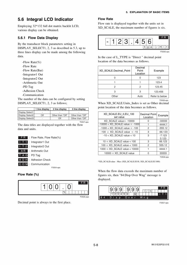
IM 01E20F02-01E5-8
5. EXPLANATION OF BASIC ITEMS
5.6 Integral LCD IndicatorEmploying 32*132 full dot matrix backlit LCD,various display can be obtained.
5.6.1 Flow Data Display
By the transducer block parameters setting inDISPLAY_SELECT1, 2, 3 as described in 5.3, up tothree lines display can be made among the followingdata.
-Flow Rate(%)-Flow Rate-Flow Rate(Bar)-Integrator1 Out-Integrator2 Out-Arithmetic Out-PD Tag-Adhesion Check-Communication
The number of the data can be configured by settingDISPLAY_SELECT1, 2, 3 as follows;
1 line display 2 line display 3 line displayDisplay Select1 - - -Display Select2 Off Other than "Off" Other than "Off"Display Select3 - Off Other than "Off"
T0507.eps
The data titles are displayed together with the flowdata and units.
F R
I T 1
I T 2
T A G
A D H
C O M
: Flow Rate, Flow Rate(%)
: Integrator1 Out
: Integrator2 Out
: Arithmetic Out
: PD Tag
: Adhesion Check
: Communication
A R
F0504.eps
Flow Rate (%)
1 0 0 . 0%
F R
F0505.eps
Decimal point is always to the first place.
Flow RateFlow rate is displayed together with the units set inXD_SCALE, the maximum number of figures is six.
- 1 2 3 . 4 5 6k g a l / i nm
F R
F0506.eps
In the case of L_TYPE is "Direct " decimal pointlocation of the data becomes as follows.
XD_SCALE.Decimal_PointXD_SCALE.Decimal_PointDesimalDesimal
PointPointLocationLocation
ExampleExample
0 0 123
1 1 123.4
2 2
3
123.45
3 123.456
Other Auto Refer to below T0508.eps
When XD_SCALE.Units_Index is set as Other decimalpoint location of the data becomes as follows.
XD_SCALE.EU_0,EU_100 XD_SCALE.EU_0,EU_100 set set valuevalue
Desimal PointDesimal PointLocationLocation
ExampleExample
XD_SCALE value� -10000 0 -33333-10000 < XD_SCALE value � -1000 1 -4444.1-1000 < XD_SCALE value � -100 2 -555.12
-100 < XD_SCALE value � -10 3 -66.123-10 < XD_SCALE value < 10 3 -7.123
0.12310 � XD_SCALE value < 100 3 66.123
100 � XD_SCALE value < 1000 2 555.12
1000 � XD_SCALE value < 10000 1 4444.1
10000 � XD_SCALE value 0 33333T0509.eps
*XD_SCALEvalue : Max (|XD_SCALE.EU0|, |XD_SCALE.EU100|)
When the flow data exceeds the maximum number offigures six, then "84:Disp Over Wng" message isdisplayed.
9 9 9 . 9 9 l / h92 3 4 5 6 M l1 I T 1
F R
pD8 4 : i s n gr WeO v
F0507.eps
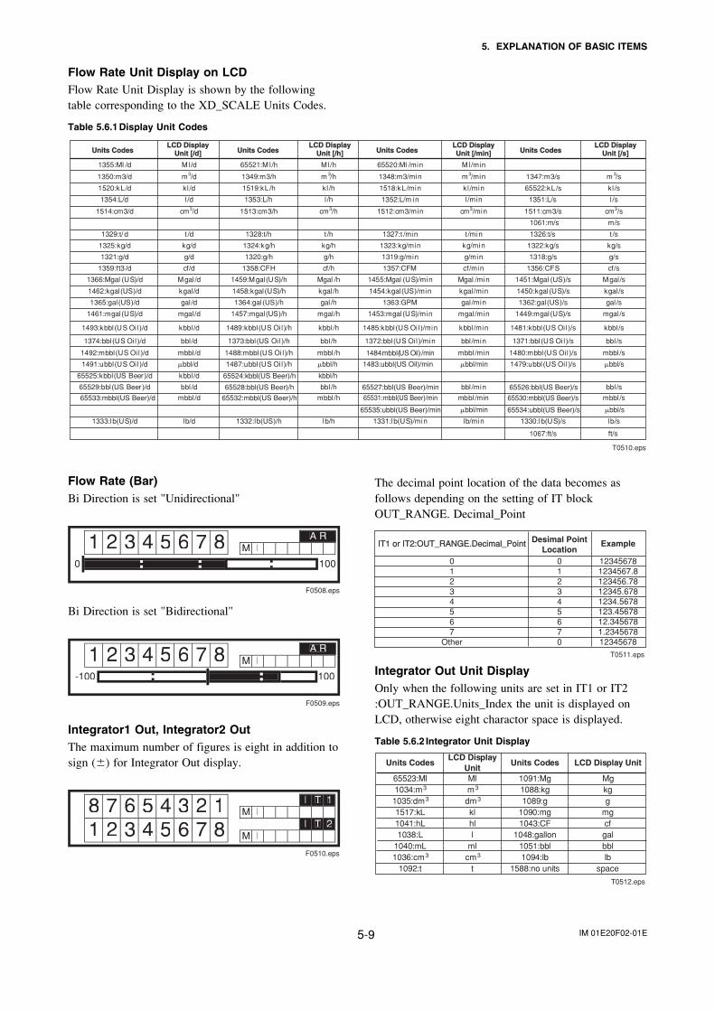
IM 01E20F02-01E5-9
5. EXPLANATION OF BASIC ITEMS
Flow Rate Unit Display on LCDFlow Rate Unit Display is shown by the followingtable corresponding to the XD_SCALE Units Codes.
Table 5.6.1 Display Unit Codes
Units CodesUnits Codes Units CodesUnits Codes Units CodesUnits Codes Units CodesUnits CodesLCD DisplayLCD Display
Unit [/d]Unit [/d]LCD DisplayLCD Display
Unit [/h]Unit [/h]LCD DisplayLCD DisplayUnit [/min]Unit [/min]
LCD DisplayLCD DisplayUnit [/s]Unit [/s]
1355:Ml /d Ml/d 65521:M l/h M l/h 65520:Ml /min M l/min
1350:m3/d m3/d 1349:m3/h m 3/h 1348:m3/min m 3/min 1347:m3/s m 3/s
1520:kL/d kl /d 1519:kL/h kl /h 1518:kL/min kl /min 65522:kL/s kl /s
1354:L/d l /d 1353:L/h l /h 1352:L/m in l /min 1351:L/s l /s
1514:cm3/d cm3/d 1513:cm3/h cm3/h 1512:cm3/min cm3/min 1511:cm3/s cm3/s
1061:m/s m/s
1329:t/ d t /d 1328:t/h t /h 1327:t /min t /min 1326:t/s t /s
1325:kg/d kg/d 1324:kg/h kg/h 1323:kg/min kg/min 1322:kg/s kg/s
1321:g/d g/d 1320:g/h g/h 1319:g/min g/min 1318:g/s g/s
1359:ft3 /d cf/d 1358:CFH cf/h 1357:CFM cf/min 1356:CFS cf/s
1366:Mgal (US)/d Mgal /d 1459:M gal(US)/h Mgal /h 1455:Mgal (US)/min Mgal /min 1451:Mgal (US)/s Mgal/s
1462:kgal(US)/d kgal/d 1458:kgal(US)/h kgal /h 1454:kgal(US)/min kgal/min 1450:kgal(US)/s kgal /s
1365:gal(US)/d gal /d 1364:gal(US)/h gal /h 1363:GPM gal/min 1362:gal(US)/s gal /s
1461:mgal(US)/d mgal /d 1457:mgal(US)/h mgal/h 1453:mgal(US)/min mgal /min 1449:mgal(US)/s mgal/s
1493:kbbl (US Oi l )/d kbbl /d 1489:kbbl (US Oi l )/h kbbl /h 1485:kbbl(US Oi l )/min kbbl /min 1481:kbbl(US Oi l )/s kbbl /s
1374:bbl (US Oi l )/d bbl /d 1373:bbl(US Oi l )/h bbl /h 1372:bbl (US Oil )/min bbl /min 1371:bbl (US Oi l )/s bbl /s
1492:mbbl(US Oi l )/d mbbl /d 1488:mbbl(US Oi l )/h mbbl /h 1484:mbbl(US Oil)/min mbbl/min 1480:mbbl(US Oil )/s mbbl /s
1491:ubbl(US Oi l )/d 1487:ubbl(US Oi l )/h 1479:ubbl(US Oi l )/s �bbl/s
65525:kbbl(US Beer)/d kbbl /d 65524:kbbl(US Beer)/h kbbl/h
65529:bbl(US Beer )/d bbl /d 65528:bbl(US Beer)/h bbl /h 65527:bbl(US Beer)/min bbl /min 65526:bbl(US Beer)/s bbl /s
65533:mbbl(US Beer)/d mbbl /d 65532:mbbl(US Beer)/h mbbl /h 65531:mbbl(US Beer)/min mbbl/min 65530:mbbl(US Beer)/s mbbl /s
65535:ubbl(US Beer)/min 65534:ubbl(US Beer)/s
1067:ft/s ft/s
1333:lb(US)/d lb/d 1332:lb(US)/h lb/h 1331:lb(US)/min lb/min 1330:lb(US)/s lb/s
�bbl/d �bbl/h �bbl/min
�bbl/min �bbl/s
1483:ubbl(US Oil)/min
T0510.eps
Flow Rate (Bar)Bi Direction is set "Unidirectional"
3 4 5 6 7 M l8 A R1 20 100
F0508.eps
Bi Direction is set "Bidirectional"
3 4 5 6 7 M l81 2-100 100
A R
F0509.eps
Integrator1 Out, Integrator2 OutThe maximum number of figures is eight in addition tosign (�) for Integrator Out display.
6 5 4 3 2 M l
3 4 5 81
M lI T 2
I T 18 71 2
F0510.eps
The decimal point location of the data becomes asfollows depending on the setting of IT blockOUT_RANGE. Decimal_Point
IT1 or IT2:OUT_RANGE.Decimal_PointIT1 or IT2:OUT_RANGE.Decimal_Point Desimal PointLocation
Example
0 0 123456781 1 1234567.82 2 123456.783 12345.6784 1234.56785 123.456786 12.3456787
34567 1.2345678
Other 0 12345678 T0511.eps
Integrator Out Unit DisplayOnly when the following units are set in IT1 or IT2:OUT_RANGE.Units_Index the unit is displayed onLCD, otherwise eight charactor space is displayed.
Table 5.6.2 Integrator Unit Display
Units CodesLCD Display
UnitUnits Codes LCD Display Unit
65523:Ml Ml 1091:Mg Mg1034:m m 1088:kg kg1035:dm dm 1089:g g1517:kL kl 1090:mg mg1041:hL hl 1043:CF cf1038:L l 1048:gallon gal
1040:mL ml 1051:bbl bbl1036:cm cm 1094:lb lb
1092:t t 1588:no units space
T0512.eps
3 3
3 3
3 3
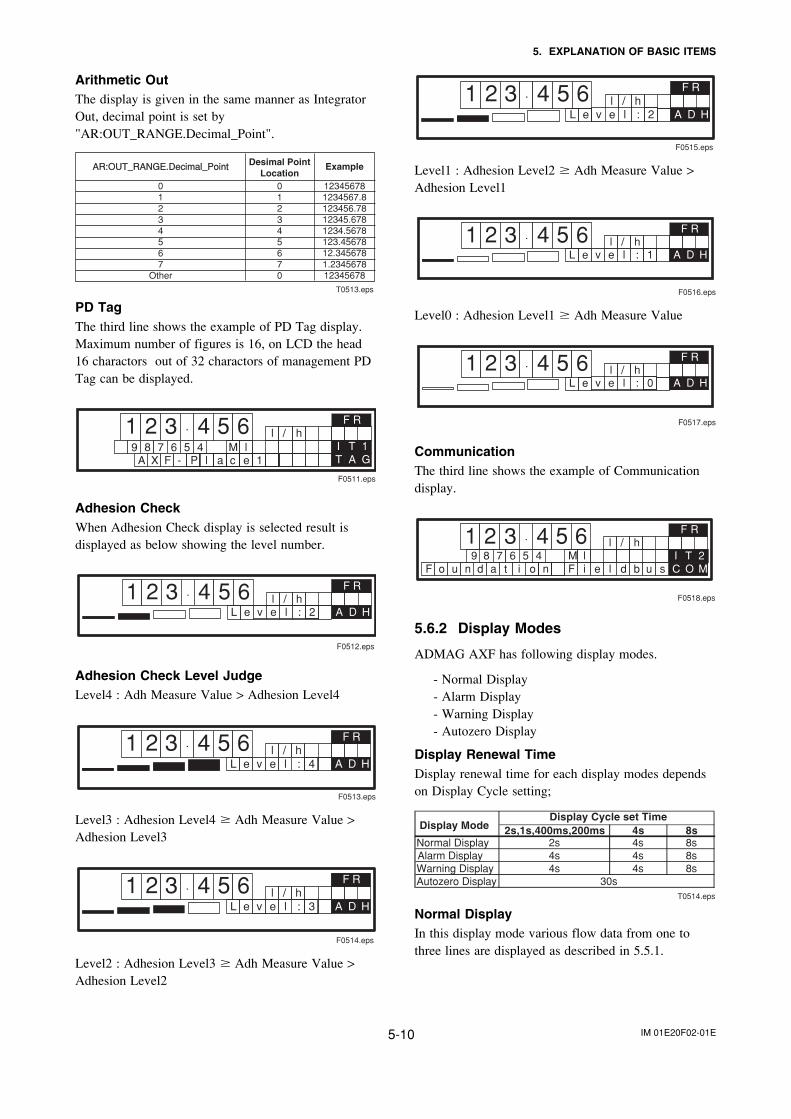
IM 01E20F02-01E5-10
5. EXPLANATION OF BASIC ITEMS
Arithmetic OutThe display is given in the same manner as IntegratorOut, decimal point is set by"AR:OUT_RANGE.Decimal_Point".
AR:OUT_RANGE.Decimal_PointAR:OUT_RANGE.Decimal_Point Desimal PointLocation
Example
0 0 123456781 1 1234567.82 2 123456.783 12345.6784 1234.56785 123.456786 12.3456787
34567 1.2345678
Other 0 12345678 T0513.eps
PD TagThe third line shows the example of PD Tag display.Maximum number of figures is 16, on LCD the head16 charactors out of 32 charactors of management PDTag can be displayed.
1 2 3 . 4 5 l / h68 7 6 5 4 M l9
T A G
F R
I T 1A X F - P l 1eca
F0511.eps
Adhesion CheckWhen Adhesion Check display is selected result isdisplayed as below showing the level number.
1 2 3 . 4 5 l / h6L e
F R
A D H:v e l 2
F0512.eps
Adhesion Check Level JudgeLevel4 : Adh Measure Value > Adhesion Level4
1 2 3 . 4 5 l / h6L e
F R
A D H:v e l 4
F0513.eps
Level3 : Adhesion Level4 � Adh Measure Value >Adhesion Level3
1 2 3 . 4 5 l / h6L e
F R
A D H:v e l 3
F0514.eps
Level2 : Adhesion Level3 � Adh Measure Value >Adhesion Level2
1 2 3 . 4 5 l / h6L e
F R
A D H:v e l 2
F0515.eps
Level1 : Adhesion Level2 � Adh Measure Value >Adhesion Level1
1 2 3 . 4 5 l / h6L e
F R
A D H:v e l 1
F0516.eps
Level0 : Adhesion Level1 � Adh Measure Value
1 2 3 . 4 5 l / h6L e
F R
A D H:v e l 0
F0517.eps
CommunicationThe third line shows the example of Communicationdisplay.
1 2 3 . 4 5 l / h68 7 6 5 4 M l9
C O M
F R
I T 2d a t i o nF o u n d b u sF i e l
F0518.eps
5.6.2 Display Modes
ADMAG AXF has following display modes.
- Normal Display- Alarm Display- Warning Display- Autozero Display
Display Renewal TimeDisplay renewal time for each display modes dependson Display Cycle setting;
2s,1s,400ms,200ms 4s 8sNormal Display 2s 4s 8sAlarm Display 4s 4s 8sWarning Display 4s 4s 8sAutozero Display
Display Cycle set Time
30s
Display Mode
T0514.eps
Normal DisplayIn this display mode various flow data from one tothree lines are displayed as described in 5.5.1.
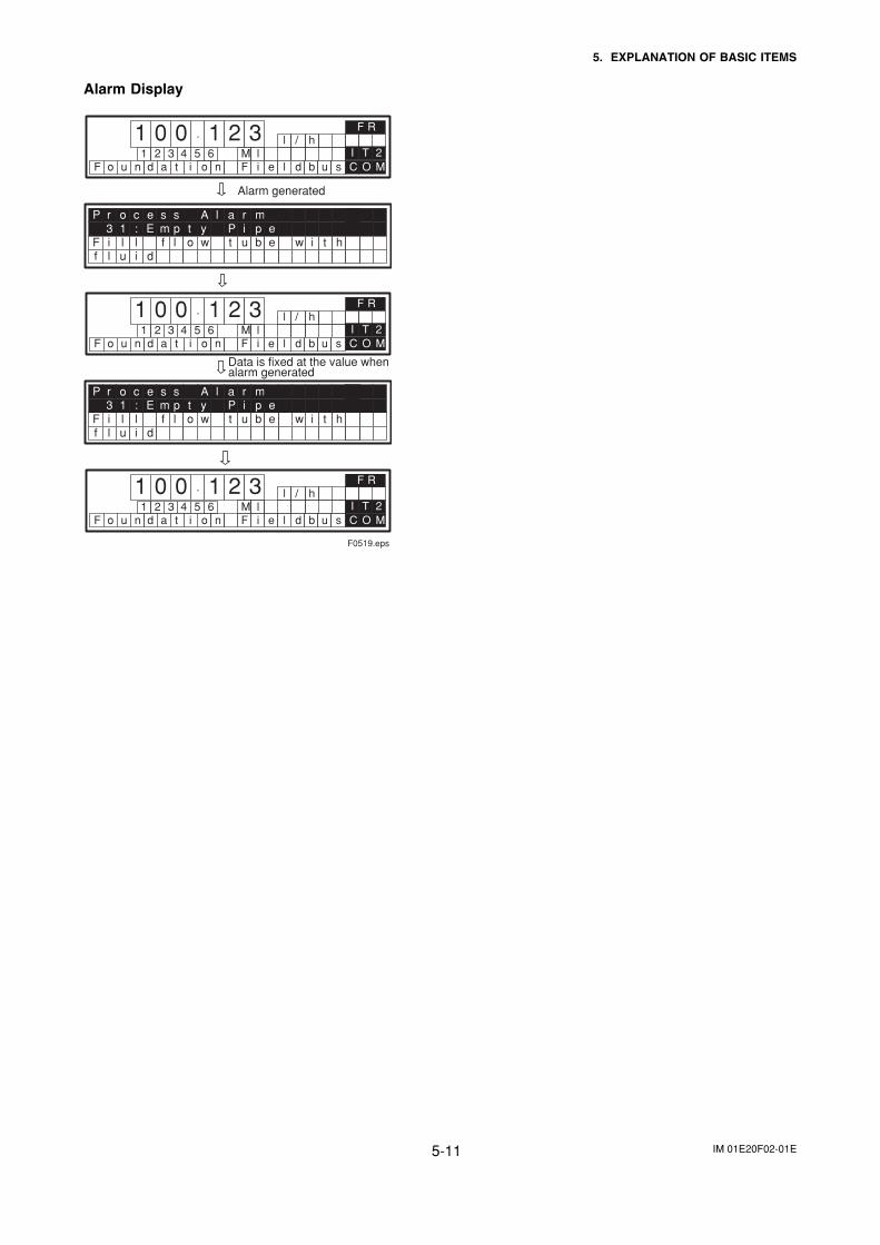
IM 01E20F02-01E5-11
5. EXPLANATION OF BASIC ITEMS
Alarm Display
1 0 0 . 1 2 l / h32 3 4 5 6 M l1 I T 2
F R
C O Md a t i o nF o u n d b u sF i e l
scP r o e s r maA lp:3 1 E m i p ePt yllF i l f wu b eto w i t h
if l u d
1 0 0 . 1 2 l / h32 3 4 5 6 M l1 I T 2
F R
C O Md a t i o nF o u n d b u sF i e l
scP r o e s r maA lp:3 1 E m i p ePt yllF i l f wu b eto w i t h
if l u d
1 0 0 . 1 2 l / h32 3 4 5 6 M l1 I T 2
F R
C O Md a t i o nF o u n d b u sF i e l
Alarm generated
Data is fixed at the value whenalarm generated
F0519.eps

IM 01E20F02-01E5-12
5. EXPLANATION OF BASIC ITEMS
Alarm Message / Countermeasure MessageOn the Integral LCD indicator following messages are displayed when alarm is generated.
Table 5.6.3 Alarm Message Display
10:uP Fault11:EEPROM Fault12:A/D(H) Fault13:A/D(L) Fault14:A/D(Z) Fault15:Coil Open16:EEPROM Dflt100:Comm uP Fault101:Comm EEPROM Fault102:IT1 Not Saved103:IT2 Not Saved104:Comm Error1105:Comm Error2106:DL Incomplete107:Download Fail108:Not Ready30:Sig Overflow31:Empty Pipe33:Adhesion Alm110:AI Lo Lo Alm111:AI Hi Hi Alm112:PID Lo Lo Alm113:PID Hi Hi Alm40:RS O/S Mode41:TB O/S Mode42:AI FB O/S Mode43:IT1 FB O/S Mode44:IT2 FB O/S Mode45:DI1 FB O/S Mode46:DI2 FB O/S Mode47:AR FB O/S Mode48:PID FB O/S Mode50:Span > 10m/s51:Span < 0.1m/s
72:Size Set Err
120:IT1 Clock Per Err121:IT2 Clock Per Err122:AR Range Set Err
Microprocessor (CPU) failureEEPROM failure
A/D converter failure
Flowtube coil is open-circuitEEPROM default valuesCommunication uP failureCommunication EEPROM failureIT1 save errorIT2 save errorAXF internal communication errorAXF internal communication errorDownload is not completedDownload failureFunction block not scheduledInput signal errorFlowtube is not filled with fluidElectrode adhesion alarmAI process alarmAI process alarmPID process alarmPID process alarmRS. MODE_BLK.Target is O/S modeTB. MODE_BLK.Target is O/S modeAI. MODE_BLK.Target is O/S modeIT1. MODE_BLK.Target is O/S modeIT2. MODE_BLK.Target is O/S modeDI1. MODE_BLK.Target is O/S modeDI2. MODE_BLK.Target is O/S modeAR. MODE_BLK.Target is O/S modePID. MODE_BLK.Target is O/S modeSpan flow velocity setting is 11 m/s or moreSpan flow velocity setting is 0.05 m/s or lessMass units have been selected for Base Flow Unit but density is set to zero.Measure Mode is set to Enhanced DF without selecting an optional code HF1 or HF2.A value of 3000.1 mm or more is set for Nominal Size.The condition in Adhesion detection level, Level:1<Level:2<Level:3<Level:4 is not satisfied.IT1 CLOCK_PER set value is smaller than excecution periodIT2 CLOCK_PER set value is smaller than excecution periodRANGE_HI>RANGE_LO is not satisfied
Check XD Scale,Density Unit,Mass Flow Density
Check Measure Mode of TB
Check Nominal Size,Nominal Size Unit
Check Adhesion Level1 to Adhesion Level 4
Check Clock Period,Period of ExecutionCheck Clock Period,Period of ExecutionCheck Range Hi and Range Lo of AR
Check XD Scale of AI
Schedule FB, or check LAS communicationCheck signal cable and groundingFill flow tube with fluid
Clean electrodes
Check the flow rate and setting valueCheck the flow rate and setting valueCheck the setting valueCheck the setting value
Check software download error code
Cut the power and check coil & EX cables
Contact nearest office or service center
Contact nearest office or service center
CategoryCategory Alarm MessageAlarm Message Countermeasure MessageCountermeasure Message Alarm DescriptionAlarm Description
ProcessAlarms
O/S ModeAlarms
SettingAlarms
SystemAlarms
T0515.eps
73:Adh Set Err
71:Meas Mod Set
57:Dens Set Err
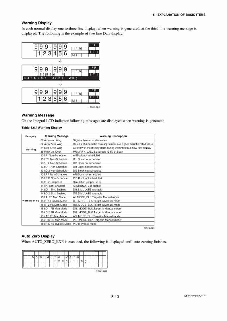
IM 01E20F02-01E5-13
5. EXPLANATION OF BASIC ITEMS
Warning DisplayIn each normal display one to three line display, when warning is generated, at the third line warning message isdisplayed. The following is the example of two line Data display.
9 9 9 . 9 9 l / h
1 2 3 4 5 69
M lI T 1
F R
9 9 9 . 9 9 l / h92 3 5 5 6 M l1 I T 1
F R
pD8 4 : i s n gr WeO v
9 9 9 . 9 9 l / h
1 2 3 6 5 69
M lI T 1
F R
F0520.eps
Warning MessageOn the Integral LCD indicator following messages are displayed when warning is generated.
Table 5.6.4 Warning Display
Category Warning Message
Warning
T0516.eps
80:Adhesion Wng82:Auto Zero Wng84:Disp Over Wng85:Flow Vel Over130:AI Non-Schedule131:IT1 Non-Schedule132:IT2 Non-Schedule133:DI1 Non-Schedule134:DI2 Non-Schedule135:AR Non-Schedule136:PID Non-Schedule140:Sim. Jmpr On141:AI Sim. Enabled142:DI1 Sim. Enabled143:DI2 Sim. Enabled150:AI FB Man Mode151:IT1 FB Man Mode152:IT2 FB Man Mode153:DI1 FB Man Mode154:DI2 FB Man Mode155:AR FB Man Mode156:PID FB Man Mode160:PID FB Bypass Mode
Slight adhesion to electrodes.Results of automatic zero adjustment are higher than the rated value.Overflow in the display digits during instantaneous flow rate displayPRIMARY_VALUE exceeds 108% of SpanAI Block not scheduledIT1 Block not scheduledIT2 Block not scheduledDI1 Block not scheduledDI2 Block not scheduledAR Block not scheduledPID Block not scheduledSimulation jumper is ONAI.SIMULATE is enableDI1.SIMULATE is enableDI2.SIMULATE is enableAI. MODE_BLK.Target is Manual modeIT1. MODE_BLK.Target is Manual modeIT2. MODE_BLK.Target is Manual modeDI1. MODE_BLK.Target is Manual modeDI2. MODE_BLK.Target is Manual modeAR. MODE_BLK.Target is Manual modePID. MODE_BLK.Target is Manual modePID is bypass mode
Warning Description
Warning in FB
Auto Zero DisplayWhen AUTO_ZERO_EXE is executed, the following is displayed until auto zeroing finishes.
AoN w oZ e ru t oi nc u teE x g . . .
F0521.eps
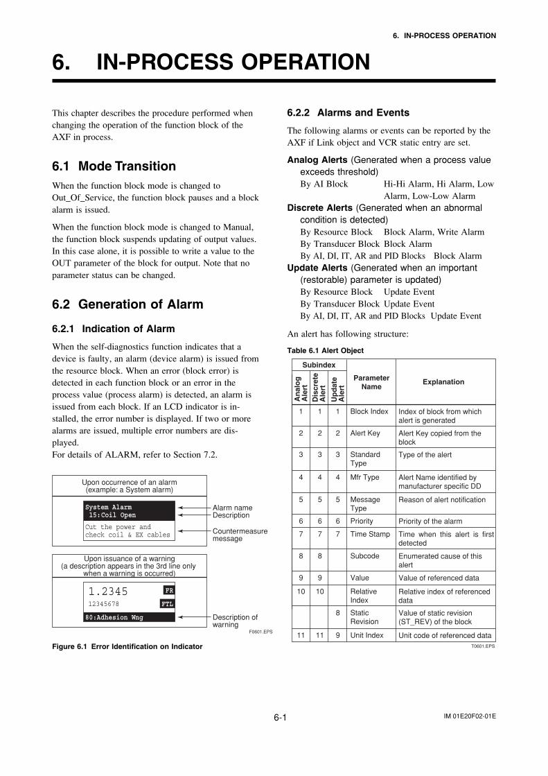
IM 01E20F02-01E6-1
6. IN-PROCESS OPERATION
6. IN-PROCESS OPERATION
This chapter describes the procedure performed whenchanging the operation of the function block of theAXF in process.
6.1 Mode TransitionWhen the function block mode is changed toOut_Of_Service, the function block pauses and a blockalarm is issued.
When the function block mode is changed to Manual,the function block suspends updating of output values.In this case alone, it is possible to write a value to theOUT parameter of the block for output. Note that noparameter status can be changed.
6.2 Generation of Alarm
6.2.1 Indication of Alarm
When the self-diagnostics function indicates that adevice is faulty, an alarm (device alarm) is issued fromthe resource block. When an error (block error) isdetected in each function block or an error in theprocess value (process alarm) is detected, an alarm isissued from each block. If an LCD indicator is in-stalled, the error number is displayed. If two or morealarms are issued, multiple error numbers are dis-played.For details of ALARM, refer to Section 7.2.
Upon occurrence of an alarm(example: a System alarm)
Upon issuance of a warning(a description appears in the 3rd line only
when a warning is occurred)
Alarm nameDescription
Countermeasure message
Description of warning
F0601.EPS
Figure 6.1 Error Identification on Indicator
6.2.2 Alarms and Events
The following alarms or events can be reported by theAXF if Link object and VCR static entry are set.
Analog Alerts (Generated when a process valueexceeds threshold)By AI Block Hi-Hi Alarm, Hi Alarm, Low
Alarm, Low-Low AlarmDiscrete Alerts (Generated when an abnormal
condition is detected)By Resource Block Block Alarm, Write AlarmBy Transducer Block Block AlarmBy AI, DI, IT, AR and PID Blocks Block Alarm
Update Alerts (Generated when an important(restorable) parameter is updated)By Resource Block Update EventBy Transducer Block Update EventBy AI, DI, IT, AR and PID Blocks Update Event
An alert has following structure:
Table 6.1 Alert Object
T0601.EPS
ParameterName
Explanation
1 Block Index Index of block from which alert is generated
2 Alert Key Alert Key copied from the block
3 Standard Type
Type of the alert
4 Mfr Type Alert Name identified by manufacturer specific DD
5
1
2
3
4
5 Message Type
Reason of alert notification
1
2
3
6 Priority Priority of the alarm
7 Time Stamp Time when this alert is first detected
6
7
6
7
8 Subcode Enumerated cause of this alert
9 Value Value of referenced data
8
9
10 Relative Index
Relative index of referenced data
Static Revision
Value of static revision (ST_REV) of the block
10
8
11 Unit Index Unit code of referenced data11 9
4
5
Subindex
An
alo
gA
lert
Dis
cret
eA
lert
Up
dat
eA
lert
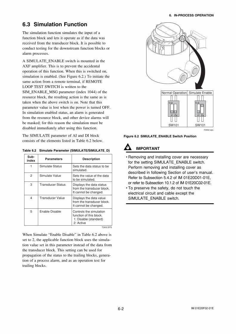
IM 01E20F02-01E6-2
6. IN-PROCESS OPERATION
6.3 Simulation FunctionThe simulation function simulates the input of afunction block and lets it operate as if the data wasreceived from the transducer block. It is possible toconduct testing for the downstream function blocks oralarm processes.
A SIMULATE_ENABLE switch is mounted in theAXF amplifier. This is to prevent the accidentaloperation of this function. When this is switched on,simulation is enabled. (See Figure 6.2.) To initiate thesame action from a remote terminal, if REMOTELOOP TEST SWITCH is written to theSIM_ENABLE_MSG parameter (index 1044) of theresource block, the resulting action is the same as istaken when the above switch is on. Note that thisparameter value is lost when the power is turned OFF.In simulation enabled status, an alarm is generatedfrom the resource block, and other device alarms willbe masked; for this reason the simulation must bedisabled immediately after using this function.
The SIMULATE parameter of AI and DI blockconsists of the elements listed in Table 6.2 below.
Table 6.2 Simulate Parameter (SIMULATE/SIMULATE_D)
T0602.EPS
Sub-index Parameters Description
1 Simulate Status Sets the data status to be simulated.
2 Simulate Value Sets the value of the data to be simulated.
3 Transducer Status Displays the data status from the transducer block. It cannot be changed.
4 Transducer Value Displays the data value from the transducer block. It cannot be changed.
5 Enable Disable Controls the simulation function of this block. 1: Disable (standard) 2: Active
When Simulate “Enable Disable” in Table 6.2 above isset to 2, the applicable function block uses the simula-tion value set in this parameter instead of the data fromthe transducer block. This setting can be used forpropagation of the status to the trailing blocks, genera-tion of a process alarm, and as an operation test fortrailing blocks.
21O N
21O N
Normal Operation Simulate Enable
SW101 SW101F0602.eps
Figure 6.2 SIMULATE_ENABLE Switch Position
IMPORTANT
• Removing and installing cover are necessaryfor the setting SIMULATE_ENABLE switch.Perform removing and installing cover asdescribed in following Section of user’s manual.Refer to Subsection 5.4.2 of IM 01E20D01-01E,or refer to Subsection 10.1.2 of IM 01E20C02-01E.
• To preserve the safety, do not touch theelectrical circuit and cable except theSIMULATE_ENABLE switch.
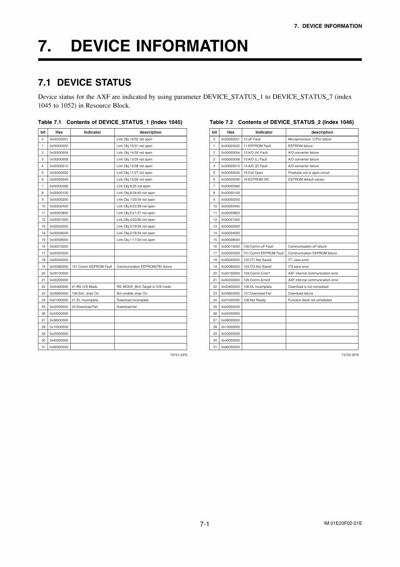
IM 01E20F02-01E7-1
7. DEVICE INFORMATION
7. DEVICE INFORMATION
7.1 DEVICE STATUSDevice status for the AXF are indicated by using parameter DEVICE_STATUS_1 to DEVICE_STATUS_7 (index1045 to 1052) in Resource Block.
Table 7.1 Contents of DEVICE_STATUS_1 (Index 1045)
T0701.EPS
0 0x00000001 Link Obj.16/32 not open
1 0x00000002 Link Obj.15/31 not open
2 0x00000004 Link Obj.14/30 not open
3 0x00000008 Link Obj.13/29 not open
4 0x00000010 Link Obj.12/28 not open
5 0x00000020 Link Obj.11/27 not open
6 0x00000040 Link Obj.10/26 not open
7 0x00000080 Link Obj.9/25 not open
8 0x00000100 Link Obj.8/24/40 not open
9 0x00000200 Link Obj.7/23/39 not open
10 0x00000400 Link Obj.6/22/38 not open
11 0x00000800 Link Obj.5/21/37 not open
12 0x00001000 Link Obj.4/20/36 not open
13 0x00002000 Link Obj.3/19/35 not open
14 0x00004000 Link Obj.2/18/34 not open
15 0x00008000 Link Obj.1/17/33 not open
16 0x00010000
17 0x00020000
18 0x00040000
19 0x00080000 101:Comm EEPROM Fault Communication EEPROM(FB) failure
20 0x00100000
21 0x00200000
22 0x00400000 41:RS O/S Mode RS. MODE_BLK.Target is O/S mode
23 0x00800000 100:Sim. Jmpr On Sim.enable Jmpr On
24 0x01000000 21:DL Incomplete Download incomplete
25 0x02000000 22:Download Fail Download fail
26 0x04000000
27 0x08000000
28 0x10000000
29 0x20000000
30 0x40000000
31 0x80000000
bit Hex Indicator description
Table 7.2 Contents of DEVICE_STATUS_2 (Index 1046)
T0702.EPS
0 0x00000001 10:uP Fault Microprocessor (CPU) failure
1 0x00000002 11:EEPROM Fault EEPROM failure
2 0x00000004 12:A/D (H) Fault A/D converter failure
3 0x00000008 13:A/D (L) Fault A/D converter failure
4 0x00000010 14:A/D (Z) Fault A/D converter failure
5 0x00000020 15:Coil Open Flowtube coil is open-circuit
6 0x00000040 16:EEPROM Dflt EEPROM default values
7 0x00000080
8 0x00000100
9 0x00000200
10 0x00000400
11 0x00000800
12 0x00001000
13 0x00002000
14 0x00004000
15 0x00008000
16 0x00010000 100:Comm uP Fault Communication uP failure
17 0x00020000 101:Comm EEPROM Fault Communication EEPROM failure
18 0x00040000 102:IT1 Not Saved IT1 save error
19 0x00080000 103:IT2 Not Saved IT2 save error
20 0x00100000 104:Comm Error1 AXF internal communication error
21 0x00200000 105:Comm Error2 AXF internal communication error
22 0x00400000 106:DL Incomplete Download is not completed
23 0x00800000 107:Download Fail Download failure
24 0x01000000 108:Not Ready Function block not scheduled
25 0x02000000
26 0x04000000
27 0x08000000
28 0x10000000
29 0x20000000
30 0x40000000
31 0x80000000
bit Hex Indicator description
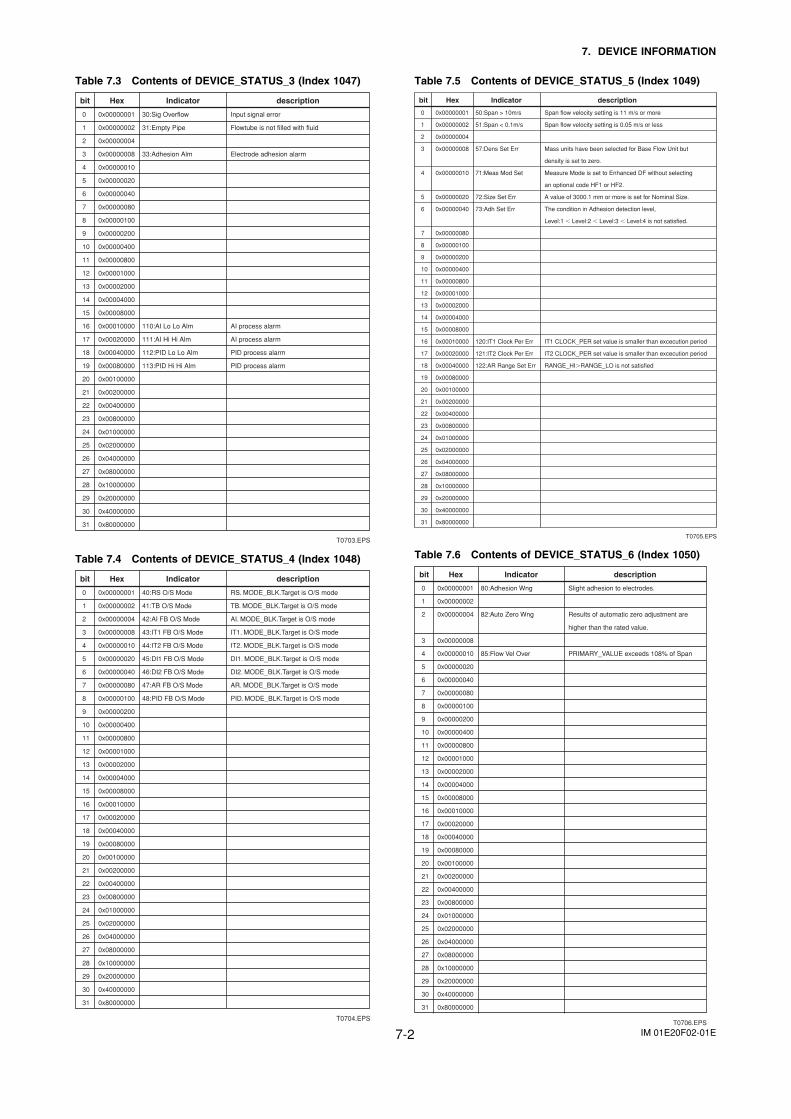
IM 01E20F02-01E7-2
7. DEVICE INFORMATION
Table 7.3 Contents of DEVICE_STATUS_3 (Index 1047)
T0703.EPS
0 0x00000001 30:Sig Overflow Input signal error
1 0x00000002 31:Empty Pipe Flowtube is not filled with fluid
2 0x00000004
3 0x00000008 33:Adhesion Alm Electrode adhesion alarm
4 0x00000010
5 0x00000020
6 0x00000040
7 0x00000080
8 0x00000100
9 0x00000200
10 0x00000400
11 0x00000800
12 0x00001000
13 0x00002000
14 0x00004000
15 0x00008000
16 0x00010000 110:AI Lo Lo Alm AI process alarm
17 0x00020000 111:AI Hi Hi Alm AI process alarm
18 0x00040000 112:PID Lo Lo Alm PID process alarm
19 0x00080000 113:PID Hi Hi Alm PID process alarm
20 0x00100000
21 0x00200000
22 0x00400000
23 0x00800000
24 0x01000000
25 0x02000000
26 0x04000000
27 0x08000000
28 0x10000000
29 0x20000000
30 0x40000000
31 0x80000000
bit Hex Indicator description
Table 7.4 Contents of DEVICE_STATUS_4 (Index 1048)
T0704.EPS
0 0x00000001 40:RS O/S Mode RS. MODE_BLK.Target is O/S mode
1 0x00000002 41:TB O/S Mode TB. MODE_BLK.Target is O/S mode
2 0x00000004 42:AI FB O/S Mode AI. MODE_BLK.Target is O/S mode
3 0x00000008 43:IT1 FB O/S Mode IT1. MODE_BLK.Target is O/S mode
4 0x00000010 44:IT2 FB O/S Mode IT2. MODE_BLK.Target is O/S mode
5 0x00000020 45:DI1 FB O/S Mode DI1. MODE_BLK.Target is O/S mode
6 0x00000040 46:DI2 FB O/S Mode DI2. MODE_BLK.Target is O/S mode
7 0x00000080 47:AR FB O/S Mode AR. MODE_BLK.Target is O/S mode
8 0x00000100 48:PID FB O/S Mode PID. MODE_BLK.Target is O/S mode
9 0x00000200
10 0x00000400
11 0x00000800
12 0x00001000
13 0x00002000
14 0x00004000
15 0x00008000
16 0x00010000
17 0x00020000
18 0x00040000
19 0x00080000
20 0x00100000
21 0x00200000
22 0x00400000
23 0x00800000
24 0x01000000
25 0x02000000
26 0x04000000
27 0x08000000
28 0x10000000
29 0x20000000
30 0x40000000
31 0x80000000
bit Hex Indicator description
Table 7.5 Contents of DEVICE_STATUS_5 (Index 1049)
T0705.EPS
0 0x00000001 50:Span > 10m/s Span flow velocity setting is 11 m/s or more
1 0x00000002 51:Span < 0.1m/s Span flow velocity setting is 0.05 m/s or less
2 0x00000004
3 0x00000008 57:Dens Set Err Mass units have been selected for Base Flow Unit but
density is set to zero.
4 0x00000010 71:Meas Mod Set Measure Mode is set to Enhanced DF without selecting
an optional code HF1 or HF2.
5 0x00000020 72:Size Set Err A value of 3000.1 mm or more is set for Nominal Size.
6 0x00000040 73:Adh Set Err The condition in Adhesion detection level,
Level:1 � Level:2 � Level:3 � Level:4 is not satisfied.
7 0x00000080
8 0x00000100
9 0x00000200
10 0x00000400
11 0x00000800
12 0x00001000
13 0x00002000
14 0x00004000
15 0x00008000
16 0x00010000 120:IT1 Clock Per Err IT1 CLOCK_PER set value is smaller than excecution period
17 0x00020000 121:IT2 Clock Per Err IT2 CLOCK_PER set value is smaller than excecution period
18 0x00040000 122:AR Range Set Err RANGE_HI�RANGE_LO is not satisfied
19 0x00080000
20 0x00100000
21 0x00200000
22 0x00400000
23 0x00800000
24 0x01000000
25 0x02000000
26 0x04000000
27 0x08000000
28 0x10000000
29 0x20000000
30 0x40000000
31 0x80000000
bit Hex Indicator description
Table 7.6 Contents of DEVICE_STATUS_6 (Index 1050)
T0706.EPS
0 0x00000001 80:Adhesion Wng Slight adhesion to electrodes.
1 0x00000002
2 0x00000004 82:Auto Zero Wng Results of automatic zero adjustment are
higher than the rated value.
3 0x00000008
4 0x00000010 85:Flow Vel Over PRIMARY_VALUE exceeds 108% of Span
5 0x00000020
6 0x00000040
7 0x00000080
8 0x00000100
9 0x00000200
10 0x00000400
11 0x00000800
12 0x00001000
13 0x00002000
14 0x00004000
15 0x00008000
16 0x00010000
17 0x00020000
18 0x00040000
19 0x00080000
20 0x00100000
21 0x00200000
22 0x00400000
23 0x00800000
24 0x01000000
25 0x02000000
26 0x04000000
27 0x08000000
28 0x10000000
29 0x20000000
30 0x40000000
31 0x80000000
bit Hex Indicator description
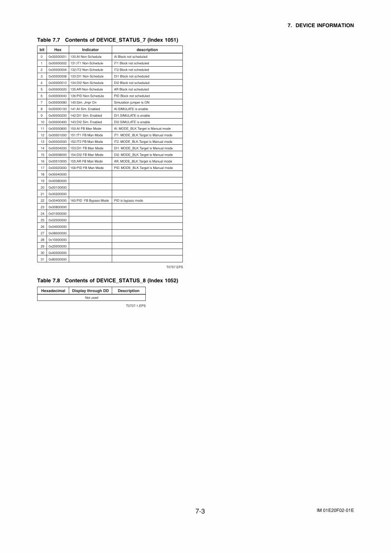
IM 01E20F02-01E7-3
7. DEVICE INFORMATION
Table 7.7 Contents of DEVICE_STATUS_7 (Index 1051)
T0707.EPS
0 0x00000001 130:AI Non-Schedule AI Block not scheduled
1 0x00000002 131:IT1 Non-Schedule IT1 Block not scheduled
2 0x00000004 132:IT2 Non-Schedule IT2 Block not scheduled
3 0x00000008 133:DI1 Non-Schedule DI1 Block not scheduled
4 0x00000010 134:DI2 Non-Schedule DI2 Block not scheduled
5 0x00000020 135:AR Non-Schedule AR Block not scheduled
6 0x00000040 136:PID Non-Schedule PID Block not scheduled
7 0x00000080 140:Sim. Jmpr On Simulation jumper is ON
8 0x00000100 141:AI Sim. Enabled AI.SIMULATE is enable
9 0x00000200 142:DI1 Sim. Enabled DI1.SIMULATE is enable
10 0x00000400 143:DI2 Sim. Enabled DI2.SIMULATE is enable
11 0x00000800 150:AI FB Man Mode AI. MODE_BLK.Target is Manual mode
12 0x00001000 151:IT1 FB Man Mode IT1. MODE_BLK.Target is Manual mode
13 0x00002000 152:IT2 FB Man Mode IT2. MODE_BLK.Target is Manual mode
14 0x00004000 153:DI1 FB Man Mode DI1. MODE_BLK.Target is Manual mode
15 0x00008000 154:DI2 FB Man Mode DI2. MODE_BLK.Target is Manual mode
16 0x00010000 155:AR FB Man Mode AR. MODE_BLK.Target is Manual mode
17 0x00020000 156:PID FB Man Mode PID. MODE_BLK.Target is Manual mode
18 0x00040000
19 0x00080000
20 0x00100000
21 0x00200000
22 0x00400000 160:PID FB Bypass Mode PID is bypass mode
23 0x00800000
24 0x01000000
25 0x02000000
26 0x04000000
27 0x08000000
28 0x10000000
29 0x20000000
30 0x40000000
31 0x80000000
bit Hex Indicator description
Table 7.8 Contents of DEVICE_STATUS_8 (Index 1052)
T0707-1.EPS
Not used
Hexadecimal Display through DD Description
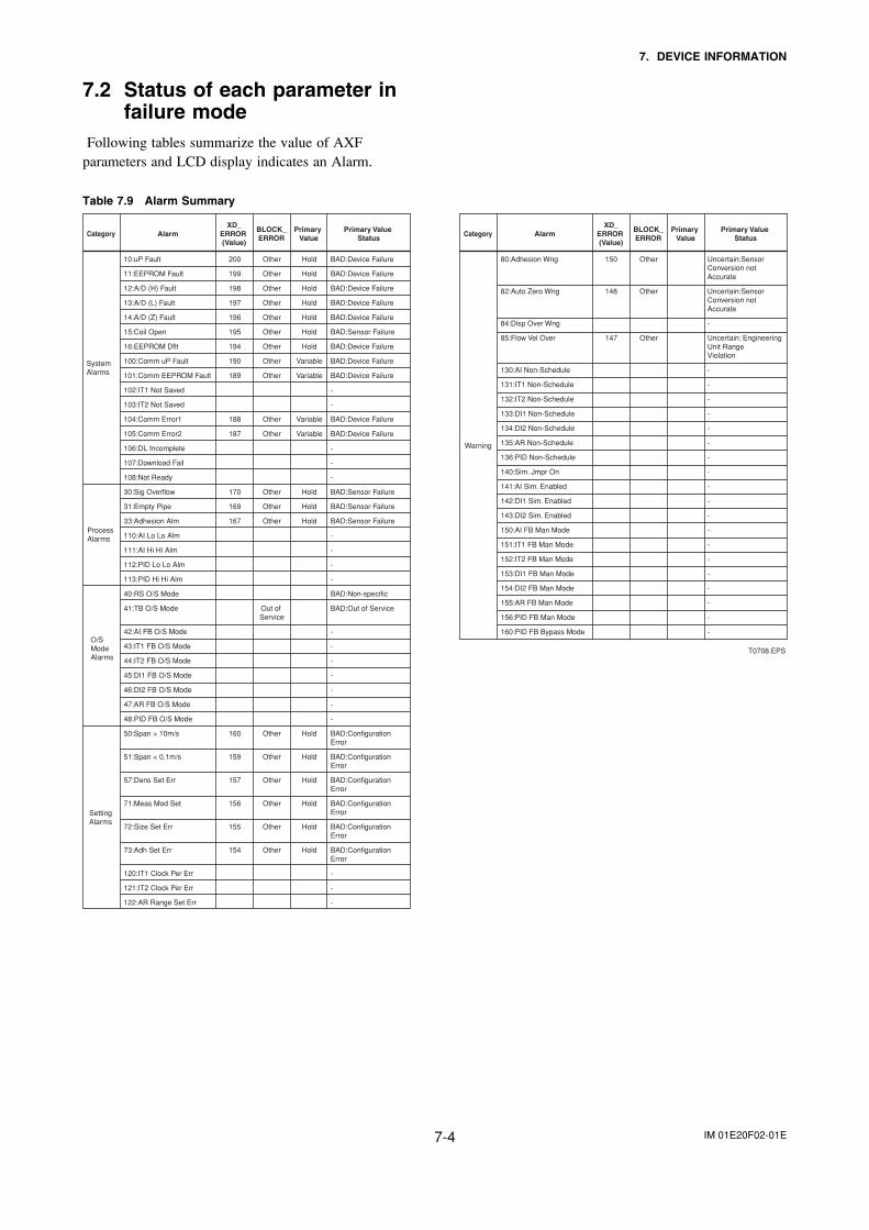
IM 01E20F02-01E7-4
7. DEVICE INFORMATION
7.2 Status of each parameter infailure mode
Following tables summarize the value of AXFparameters and LCD display indicates an Alarm.
Table 7.9 Alarm Summary
T0708.EPS
10:uP Fault 200 Other Hold BAD:Device Failure
11:EEPROM Fault 199 Other Hold BAD:Device Failure
12:A/D (H) Fault 198 Other Hold BAD:Device Failure
13:A/D (L) Fault 197 Other Hold BAD:Device Failure
14:A/D (Z) Fault 196 Other Hold BAD:Device Failure
15:Coil Open 195 Other Hold BAD:Sensor Failure
16:EEPROM Dflt 194 Other Hold BAD:Device Failure
100:Comm uP Fault 190 Other Variable BAD:Device Failure
101:Comm EEPROM Fault 189 Other Variable BAD:Device Failure
102:IT1 Not Saved -
103:IT2 Not Saved -
104:Comm Error1 188 Other Variable BAD:Device Failure
105:Comm Error2 187 Other Variable BAD:Device Failure
106:DL Incomplete -
107:Download Fail -
108:Not Ready -
30:Sig Overflow 170 Other Hold BAD:Sensor Failure
31:Empty Pipe 169 Other Hold BAD:Sensor Failure
33:Adhesion Alm 167 Other Hold BAD:Sensor Failure
110:AI Lo Lo Alm -
111:AI Hi Hi Alm -
112:PID Lo Lo Alm -
113:PID Hi Hi Alm -
40:RS O/S Mode BAD:Non-specific
41:TB O/S Mode Out of BAD:Out of Service Service
42:AI FB O/S Mode -
43:IT1 FB O/S Mode -
44:IT2 FB O/S Mode -
45:DI1 FB O/S Mode -
46:DI2 FB O/S Mode -
47:AR FB O/S Mode -
48:PID FB O/S Mode -
50:Span > 10m/s 160 Other Hold BAD:Configuration Error
51:Span < 0.1m/s 159 Other Hold BAD:Configuration Error
57:Dens Set Err 157 Other Hold BAD:Configuration Error
71:Meas Mod Set 156 Other Hold BAD:Configuration Error
72:Size Set Err 155 Other Hold BAD:Configuration Error
73:Adh Set Err 154 Other Hold BAD:Configuration Error
120:IT1 Clock Per Err -
121:IT2 Clock Per Err -
122:AR Range Set Err -
Category AlarmXD_
ERROR (Value)
BLOCK_ERROR
Primary Value
Primary Value Status
System Alarms
Process Alarms
O/S Mode Alarms
Setting Alarms
80:Adhesion Wng 150 Other Uncertain:Sensor Conversion not Accurate
82:Auto Zero Wng 148 Other Uncertain:Sensor Conversion not Accurate
84:Disp Over Wng -
85:Flow Vel Over 147 Other Uncertain: Engineering Unit Range Violation
130:AI Non-Schedule -
131:IT1 Non-Schedule -
132:IT2 Non-Schedule -
133:DI1 Non-Schedule -
134:DI2 Non-Schedule -
135:AR Non-Schedule -
136:PID Non-Schedule -
140:Sim. Jmpr On -
141:AI Sim. Enabled -
142:DI1 Sim. Enabled -
143:DI2 Sim. Enabled -
150:AI FB Man Mode -
151:IT1 FB Man Mode -
152:IT2 FB Man Mode -
153:DI1 FB Man Mode -
154:DI2 FB Man Mode -
155:AR FB Man Mode -
156:PID FB Man Mode -
160:PID FB Bypass Mode -
Category AlarmXD_
ERROR (Value)
BLOCK_ERROR
Primary Value
Primary Value Status
Warning
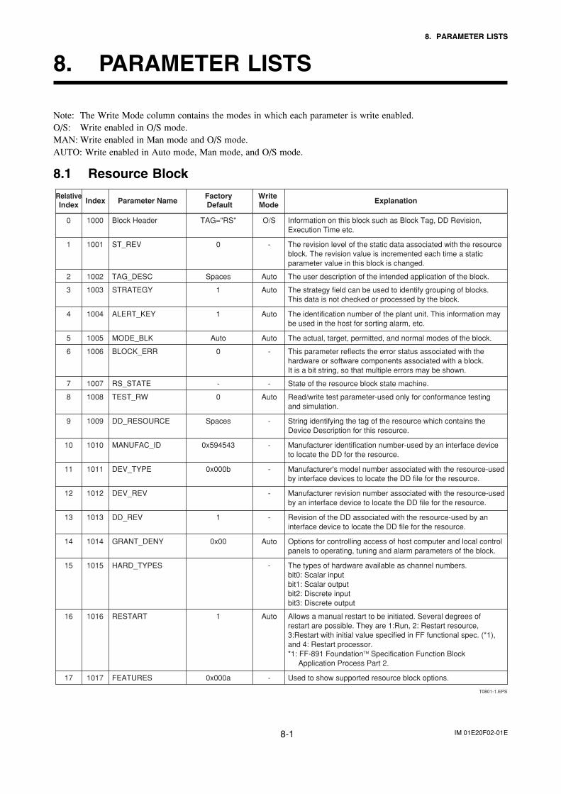
IM 01E20F02-01E8-1
8. PARAMETER LISTS
8. PARAMETER LISTS
Note: The Write Mode column contains the modes in which each parameter is write enabled.O/S: Write enabled in O/S mode.MAN: Write enabled in Man mode and O/S mode.AUTO: Write enabled in Auto mode, Man mode, and O/S mode.
8.1 Resource Block
T0801-1.EPS
Write Mode Explanation
Factory Default
RelativeIndex Parameter NameIndex
Information on this block such as Block Tag, DD Revision, Execution Time etc.
The revision level of the static data associated with the resource block. The revision value is incremented each time a static parameter value in this block is changed.
The user description of the intended application of the block.
The strategy field can be used to identify grouping of blocks. This data is not checked or processed by the block.
The identification number of the plant unit. This information may be used in the host for sorting alarm, etc.
The actual, target, permitted, and normal modes of the block.
This parameter reflects the error status associated with the hardware or software components associated with a block. It is a bit string, so that multiple errors may be shown.
State of the resource block state machine.
Read/write test parameter-used only for conformance testing and simulation.
String identifying the tag of the resource which contains the Device Description for this resource.
Manufacturer identification number-used by an interface device to locate the DD for the resource.
Manufacturer's model number associated with the resource-used by interface devices to locate the DD file for the resource.
Manufacturer revision number associated with the resource-used by an interface device to locate the DD file for the resource.
Revision of the DD associated with the resource-used by an interface device to locate the DD file for the resource.
Options for controlling access of host computer and local control panels to operating, tuning and alarm parameters of the block.
The types of hardware available as channel numbers.bit0: Scalar inputbit1: Scalar outputbit2: Discrete inputbit3: Discrete output
Allows a manual restart to be initiated. Several degrees of restart are possible. They are 1:Run, 2: Restart resource, 3:Restart with initial value specified in FF functional spec. (*1), and 4: Restart processor.*1: FF-891 FoundationTM Specification Function Block
Application Process Part 2.
Used to show supported resource block options.
0 1000 Block Header TAG="RS" O/S
1 1001 ST_REV 0 -
2 1002 TAG_DESC Spaces Auto
3 1003 STRATEGY 1 Auto
4 1004 ALERT_KEY 1 Auto
5 1005 MODE_BLK Auto Auto
6 1006 BLOCK_ERR 0 -
7 1007 RS_STATE - -
8 1008 TEST_RW 0 Auto
13 1013 DD_REV 1 -
14 1014 GRANT_DENY 0x00 Auto
15 1015 HARD_TYPES -
16 1016 RESTART 1 Auto
17 1017 FEATURES 0x000a -
9 1009 DD_RESOURCE Spaces -
10 1010 MANUFAC_ID 0x594543 -
11 1011 DEV_TYPE 0x000b -
12 1012 DEV_REV -
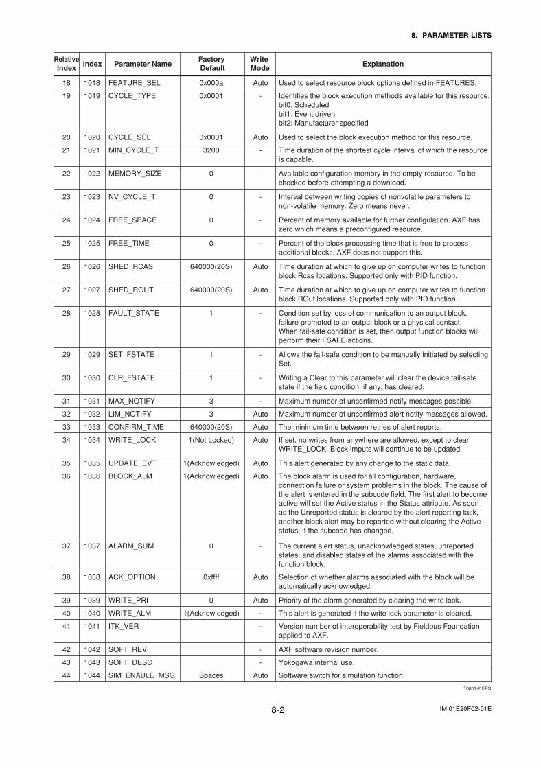
IM 01E20F02-01E8-2
8. PARAMETER LISTS
T0801-2.EPS
Write Mode Explanation
Factory Default
RelativeIndex Parameter NameIndex
Used to select resource block options defined in FEATURES.
Identifies the block execution methods available for this resource.bit0: Scheduledbit1: Event drivenbit2: Manufacturer specified
Used to select the block execution method for this resource.
Time duration of the shortest cycle interval of which the resource is capable.
Available configuration memory in the empty resource. To be checked before attempting a download.
Interval between writing copies of nonvolatile parameters to non-volatile memory. Zero means never.
Percent of memory available for further configulation. AXF has zero which means a preconfigured resource.
Percent of the block processing time that is free to process additional blocks. AXF does not support this.
Time duration at which to give up on computer writes to function block Rcas locations. Supported only with PID function.
Time duration at which to give up on computer writes to function block ROut locations. Supported only with PID function.
Condition set by loss of communication to an output block, failure promoted to an output block or a physical contact. When fail-safe condition is set, then output function blocks will perform their FSAFE actions.
Allows the fail-safe condition to be manually initiated by selecting Set.
Writing a Clear to this parameter will clear the device fail-safe state if the field condition, if any, has cleared.
Maximum number of unconfirmed notify messages possible.
Maximum number of unconfirmed alert notify messages allowed.
The minimum time between retries of alert reports.
If set, no writes from anywhere are allowed, except to clear WRITE_LOCK. Block imputs will continue to be updated.
This alert generated by any change to the static data.
The block alarm is used for all configuration, hardware, connection failure or system problems in the block. The cause of the alert is entered in the subcode field. The first alert to become active will set the Active status in the Status attribute. As soon as the Unreported status is cleared by the alert reporting task, another block alert may be reported without clearing the Active status, if the subcode has changed.
The current alert status, unacknowledged states, unreported states, and disabled states of the alarms associated with the function block.
Selection of whether alarms associated with the block will be automatically acknowledged.
Priority of the alarm generated by clearing the write lock.
This alert is generated if the write lock parameter is cleared.
Version number of interoperability test by Fieldbus Foundation applied to AXF.
AXF software revision number.
Yokogawa internal use.
Software switch for simulation function.
19 1019 CYCLE_TYPE 0x0001 -
21 1021 MIN_CYCLE_T 3200 -
22 1022 MEMORY_SIZE 0 -
23 1023 NV_CYCLE_T 0 -
24 1024 FREE_SPACE 0 -
25 1025 FREE_TIME 0 -
26 1026 SHED_RCAS 640000(20S) Auto
27 1027 SHED_ROUT 640000(20S) Auto
28 1028 FAULT_STATE 1 -
31 1031 MAX_NOTIFY 3 -
32 1032 LIM_NOTIFY 3 Auto
33 1033 CONFIRM_TIME 640000(20S) Auto
34 1034 WRITE_LOCK 1(Not Locked) Auto
35 1035 UPDATE_EVT 1(Acknowledged) Auto
36 1036 BLOCK_ALM 1(Acknowledged) Auto
40 1040 WRITE_ALM 1(Acknowledged) -
41 1041 ITK_VER -
37 1037 ALARM_SUM 0 -
38 1038 ACK_OPTION 0xffff Auto
39 1039 WRITE_PRI 0 Auto
42 1042 SOFT_REV -
43 1043 SOFT_DESC -
44 1044 SIM_ENABLE_MSG Spaces Auto
29 1029 SET_FSTATE 1 -
30 1030 CLR_FSTATE 1 -
20 1020 CYCLE_SEL 0x0001 Auto
18 1018 FEATURE_SEL 0x000a Auto
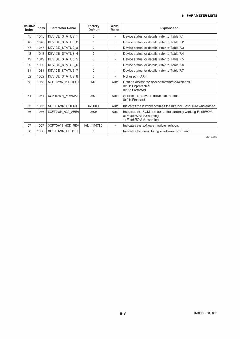
IM 01E20F02-01E8-3
8. PARAMETER LISTS
Write Mode Explanation
Factory Default
RelativeIndex Parameter NameIndex
Device status for details, refer to Table 7.1.
Device status for details, refer to Table 7.2.
Device status for details, refer to Table 7.3.
Device status for details, refer to Table 7.4.
Device status for details, refer to Table 7.5.
Device status for details, refer to Table 7.6.
Device status for details, refer to Table 7.7.
Not used in AXF.
Defines whether to accept software downloads.0x01: Unprotected0x02: Protected
Selects the software download method.0x01: Standard
Indicates the number of times the internal FlashROM was erased.
Indicates the ROM number of the currently working FlashROM.0: FlashROM #0 working1: FlashROM #1 working
Indicates the software module revision.
Indicates the error during a software download.
45 1045 DEVICE_STATUS_1 0 -
46 1046 DEVICE_STATUS_2 0 -
47 1047 DEVICE_STATUS_3 0 -
48 1048 DEVICE_STATUS_4 0 -
49 1049 DEVICE_STATUS_5 0 -
50 1050 DEVICE_STATUS_6 0 -
51 1051 DEVICE_STATUS_7 0 -
52 1052 DEVICE_STATUS_8 0 -
53 1053 SOFTDWN_PROTECT 0x01 Auto
54 1054 SOFTDWN_FORMAT 0x01 Auto
55 1055 SOFTDWN_COUNT 0x0000 Auto
56 1056 SOFTDWN_ACT_AREA 0x00 Auto
57 1057 SOFTDWN_MOD_REV [0]:1,[1]-[7]:0 -
58 1058 SOFTDWN_ERROR 0 -
T0801-3.EPS
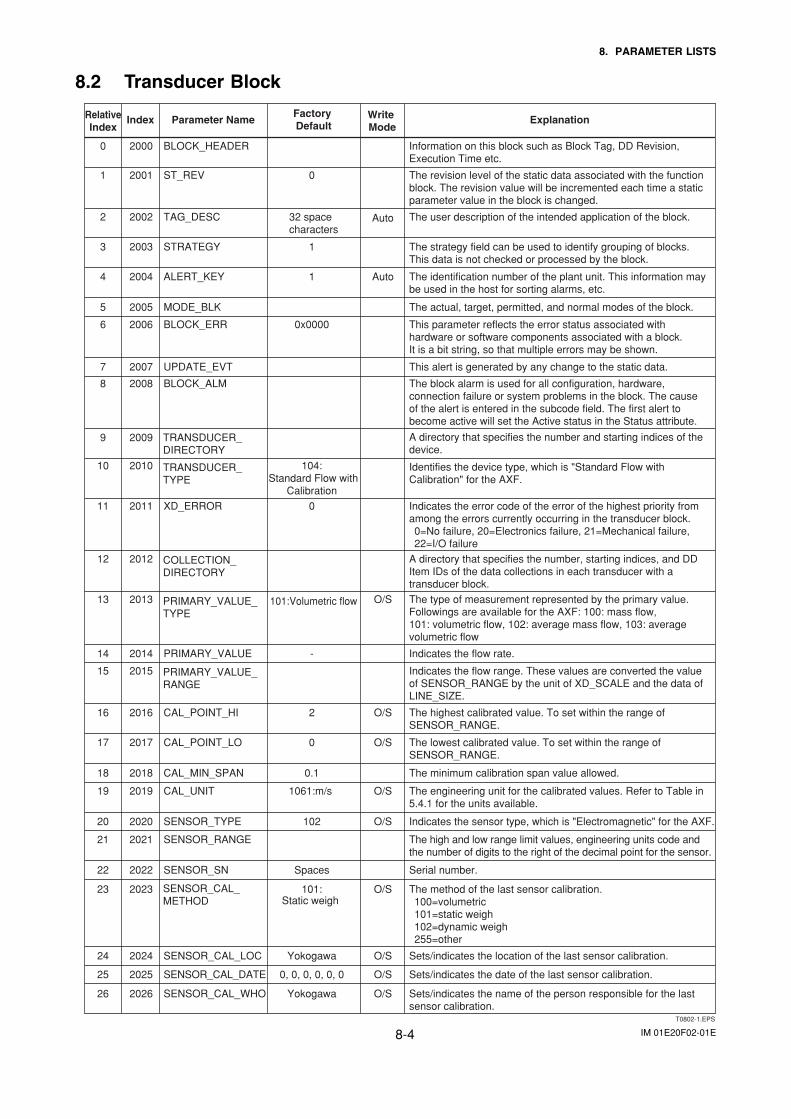
IM 01E20F02-01E8-4
8. PARAMETER LISTS
8.2 Transducer Block
T0802-1.EPS
Write Mode
ExplanationFactory Default
RelativeIndex
Parameter NameIndex
Information on this block such as Block Tag, DD Revision, Execution Time etc.
The revision level of the static data associated with the function block. The revision value will be incremented each time a static parameter value in the block is changed.
The user description of the intended application of the block.
The strategy field can be used to identify grouping of blocks. This data is not checked or processed by the block.
The identification number of the plant unit. This information may be used in the host for sorting alarms, etc.
The actual, target, permitted, and normal modes of the block.
This parameter reflects the error status associated with hardware or software components associated with a block. It is a bit string, so that multiple errors may be shown.
This alert is generated by any change to the static data.
The block alarm is used for all configuration, hardware, connection failure or system problems in the block. The cause of the alert is entered in the subcode field. The first alert to become active will set the Active status in the Status attribute.
A directory that specifies the number and starting indices of the device.
Identifies the device type, which is "Standard Flow with Calibration" for the AXF.
Indicates the error code of the error of the highest priority from among the errors currently occurring in the transducer block.0=No failure, 20=Electronics failure, 21=Mechanical failure, 22=I/O failure
A directory that specifies the number, starting indices, and DD Item IDs of the data collections in each transducer with a transducer block.
The type of measurement represented by the primary value. Followings are available for the AXF: 100: mass flow, 101: volumetric flow, 102: average mass flow, 103: average volumetric flow
Indicates the flow rate.
Indicates the flow range. These values are converted the value of SENSOR_RANGE by the unit of XD_SCALE and the data of LINE_SIZE.
The highest calibrated value. To set within the range of SENSOR_RANGE.
The lowest calibrated value. To set within the range of SENSOR_RANGE.
The minimum calibration span value allowed.
The engineering unit for the calibrated values. Refer to Table in 5.4.1 for the units available.
Indicates the sensor type, which is "Electromagnetic" for the AXF.
The high and low range limit values, engineering units code and the number of digits to the right of the decimal point for the sensor.
Serial number.
The method of the last sensor calibration.100=volumetric101=static weigh102=dynamic weigh255=other
Sets/indicates the location of the last sensor calibration.
Sets/indicates the date of the last sensor calibration.
Sets/indicates the name of the person responsible for the last sensor calibration.
1 2001 ST_REV 0
3 2003 STRATEGY 1
4 2004 ALERT_KEY 1 Auto
5 2005 MODE_BLK
6 2006 BLOCK_ERR 0x0000
7 2007 UPDATE_EVT
8 2008 BLOCK_ALM
9 2009
10 2010 104: Standard Flow with Calibration
13 2013 O/S
14 2014 PRIMARY_VALUE -
15 2015
16 2016 CAL_POINT_HI 2 O/S
17 2017 CAL_POINT_LO 0 O/S
18 2018 CAL_MIN_SPAN 0.1
22 2022 SENSOR_SN Spaces
23 2023 101: O/S
19 2019 CAL_UNIT 1061:m/s O/S
20 2020 SENSOR_TYPE 102 O/S
21 2021 SENSOR_RANGE
24 2024 SENSOR_CAL_LOC Yokogawa O/S
25 2025 SENSOR_CAL_DATE 0, 0, 0, 0, 0, 0 O/S
26 2026 SENSOR_CAL_WHO Yokogawa O/S
11 2011 XD_ERROR 0
12 2012
2 2002 TAG_DESC
0 2000 BLOCK_HEADER
TRANSDUCER_DIRECTORY
TRANSDUCER_TYPE
COLLECTION_DIRECTORY
PRIMARY_VALUE_RANGE
PRIMARY_VALUE_TYPE
SENSOR_CAL_METHOD
101:Volumetric flow
32 space characters
Auto
Static weigh
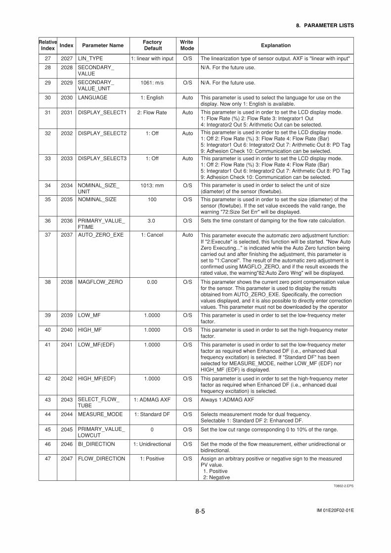
IM 01E20F02-01E8-5
8. PARAMETER LISTS
T0802-2.EPS
Write Mode Explanation
Factory Default
RelativeIndex Parameter NameIndex
The linearization type of sensor output. AXF is "linear with input"
N/A. For the future use.
N/A. For the future use.
This parameter is used to select the language for use on the display. Now only 1: English is available.
This parameter is used in order to set the LCD display mode.1: Flow Rate (%) 2: Flow Rate 3: Integrator1 Out 4: Integrator2 Out 5: Arithmetic Out can be selected.
This parameter is used in order to set the LCD display mode.1: Off 2: Flow Rate (%) 3: Flow Rate 4: Flow Rate (Bar) 5: Integrator1 Out 6: Integrator2 Out 7: Arithmetic Out 8: PD Tag 9: Adhesion Check 10: Communication can be selected.This parameter is used in order to set the LCD display mode.1: Off 2: Flow Rate (%) 3: Flow Rate 4: Flow Rate (Bar) 5: Integrator1 Out 6: Integrator2 Out 7: Arithmetic Out 8: PD Tag 9: Adhesion Check 10: Communication can be selected.
This parameter is used in order to select the unit of size (diameter) of the sensor (flowtube).
This parameter is used in order to set the size (diameter) of the sensor (flowtube). If the set value exceeds the valid range, the warning "72:Size Set Err" will be displayed.
Sets the time constant of damping for the flow rate calculation.
This parameter execute the automatic zero adjustment function: If "2:Execute" is selected, this function will be started. "Now Auto Zero Executing..." is indicated whle the Auto Zero function being carried out and after finishing the adjustment, this parameter is set to "1:Cancel". The result of the automatic zero adjustment is confirmed using MAGFLO_ZERO, and if the result exceeds the rated value, the warning"82:Auto Zero Wng" will be displayed.
This parameter shows the current zero point compensation value for the sensor. This parameter is used to display the results obtained from AUTO_ZERO_EXE. Specifically, the correction values displayed, and it is also possible to directly enter correction values. This parameter must not be downloaded by the operator
This parameter is used in order to set the low-frequency meter factor.
This parameter is used in order to set the high-frequency meter factor.
This parameter is used in order to set the low-frequency meter factor as required when Enhanced DF (i.e., enhanced dual frequency excitation) is selected. If "Standard DF" has been selected for MEASURE_MODE, neither LOW_MF (EDF) nor HIGH_MF (EDF) is displayed.
This parameter is used in order to set the high-frequency meter factor as required when Enhanced DF (i.e., enhanced dual frequency excitation) is selected.
Always 1:ADMAG AXF
Selects measurement mode for dual frequency. Selectable 1: Standard DF 2: Enhanced DF.
Set the low cut range corresponding 0 to 10% of the range.
Set the mode of the flow measurement, either unidirectional or bidirectional.
28 2028
30 2030 LANGUAGE 1: English Auto
31 2031 DISPLAY_SELECT1 2: Flow Rate Auto
32 2032 DISPLAY_SELECT2 1: Off Auto
33 2033 DISPLAY_SELECT3 1: Off Auto
34 2034 1013: mm O/S
35 2035 NOMINAL_SIZE 100 O/S
36 2036 3.0 O/S
37 2037 AUTO_ZERO_EXE 1: Cancel Auto
40 2040 HIGH_MF 1.0000 O/S
41 2041 LOW_MF(EDF) 1.0000 O/S
42 2042 HIGH_MF(EDF) 1.0000 O/S
43 2043 1: ADMAG AXF O/S
44 2044 MEASURE_MODE 1: Standard DF O/S
45 2045 0 O/S
46 2046 BI_DIRECTION 1: Unidirectional O/S
Assign an arbitrary positive or negative sign to the measured PV value.1. Positive2: Negative
47 2047 FLOW_DIRECTION 1: Positive O/S
38 2038 MAGFLOW_ZERO 0.00 O/S
39 2039 LOW_MF 1.0000 O/S
29 2029 1061: m/s O/S
27 2027 LIN_TYPE 1: linear with input O/S
PRIMARY_VALUE_FTIME
NOMINAL_SIZE_UNIT
SECONDARY_VALUE_UNIT
SECONDARY_VALUE
SELECT_FLOW_TUBE
PRIMARY_VALUE_LOWCUT
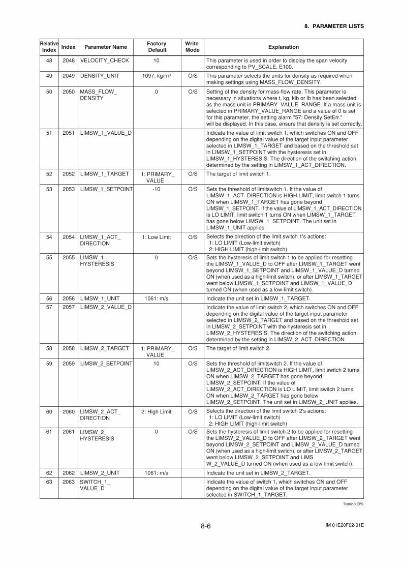
IM 01E20F02-01E8-6
8. PARAMETER LISTS
T0802-3.EPS
Write Mode Explanation
Factory Default
RelativeIndex Parameter NameIndex
This parameter is used in order to display the span velocity corresponding to PV_SCALE. E100.
This parameter selects the units for density as required when making settings using MASS_FLOW_DENSITY.
Setting of the density for mass-flow rate. This parameter is necessary in situations where t, kg, klb or lb has been selected as the mass unit in PRIMARY_VALUE_RANGE. If a mass unit is selected in PRIMARY_VALUE_RANGE and a value of 0 is set for this parameter, the setting alarm "57: Density SetErr." will be displayed. In this case, ensure that density is set correctly.
Indicate the value of limit switch 1, which switches ON and OFF depending on the digital value of the target input parameter selected in LIMSW_1_TARGET and based on the threshold set in LIMSW_1_SETPOINT with the hysteresis set in LIMSW_1_HYSTERESIS. The direction of the switching action determined by the setting in LIMSW_1_ACT_DIRECTION.
The target of limit switch 1.
Sets the threshold of limitswitch 1. If the value of LIMSW_1_ACT_DIRECTION is HIGH LIMIT, limit switch 1 turns ON when LIMSW_1_TARGET has gone beyond LIMSW_1_SETPOINT. If the value of LIMSW_1_ACT_DIRECTION is LO LIMIT, limit switch 1 turns ON when LIMSW_1_TARGET has gone below LIMSW_1_SETPOINT. The unit set in LIMSW_1_UNIT applies.
Selects the direction of the limit switch 1's actions:1: LO LIMIT (Low-limit switch) 2: HIGH LIMIT (high-limit switch)
Sets the hysteresis of limit switch 1 to be applied for resetting the LIMSW_1_VALUE_D to OFF after LIMSW_1_TARGET went beyond LIMSW_1_SETPOINT and LIMSW_1_VALUE_D turned ON (when used as a high-limit switch), or after LIMSW_1_TARGET went below LIMSW_1_SETPOINT and LIMSW_1_VALUE_D turned ON (when used as a low-limit switch).
Indicate the unit set in LIMSW_1_TARGET.
Indicate the value of limit switch 2, which switches ON and OFF depending on the digital value of the target input parameter selected in LIMSW_2_TARGET and based on the threshold set in LIMSW_2_SETPOINT with the hysteresis set in LIMSW_2_HYSTERESIS. The direction of the switching action determined by the setting in LIMSW_2_ACT_DIRECTION.
The target of limit switch 2.
Sets the threshold of limitswitch 2. If the value of LIMSW_2_ACT_DIRECTION is HIGH LIMIT, limit switch 2 turns ON when LIMSW_2_TARGET has gone beyond LIMSW_2_SETPOINT. If the value of LIMSW_2_ACT_DIRECTION is LO LIMIT, limit switch 2 turns ON when LIMSW_2_TARGET has gone below LIMSW_2_SETPOINT. The unit set in LIMSW_2_UNIT applies.
Selects the direction of the limit switch 2's actions:1: LO LIMIT (Low-limit switch)2: HIGH LIMIT (high-limit switch)
Sets the hysteresis of limit switch 2 to be applied for resetting the LIMSW_2_VALUE_D to OFF after LIMSW_2_TARGET went beyond LIMSW_2_SETPOINT and LIMSW_2_VALUE_D turned ON (when used as a high-limit switch), or after LIMSW_2_TARGET went below LIMSW_2_SETPOINT and LIMSW_2_VALUE_D turned ON (when used as a low-limit switch).
48 2048 VELOCITY_CHECK 10
50 2050 0 O/S
51 2051 LIMSW_1_VALUE_D
52 2052 LIMSW_1_TARGET O/S
53 2053 LIMSW_1_SETPOINT -10 O/S
54 2054 1: Low Limit O/S
55 2055 0 O/S
56 2056 LIMSW_1_UNIT 1061: m/s
57 2057 LIMSW_2_VALUE_D
60 2060 2: High Limit O/S
61 2061 0 O/S
Indicate the unit set in LIMSW_2_TARGET. 62 2062 LIMSW_2_UNIT 1061: m/s
Indicate the value of switch 1, which switches ON and OFF depending on the digital value of the target input parameter selected in SWITCH_1_TARGET.
63 2063
58 2058 LIMSW_2_TARGET O/S
59 2059 LIMSW_2_SETPOINT 10 O/S
49 2049 DENSITY_UNIT 1097: kg/m3 O/S
LIMSW_1_ACT_DIRECTION
LIMSW_1_HYSTERESIS
MASS_FLOW_DENSITY
LIMSW_2_HYSTERESIS
LIMSW_2_ACT_DIRECTION
1: PRIMARY_VALUE
1: PRIMARY_VALUE
SWITCH_1_VALUE_D
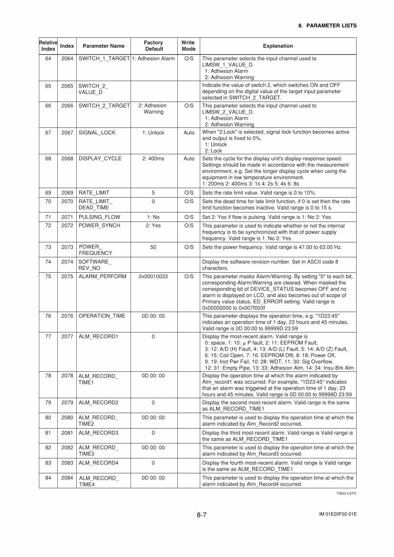
IM 01E20F02-01E8-7
8. PARAMETER LISTS
T0802-4.EPS
Write Mode Explanation
Factory Default
RelativeIndex Parameter NameIndex
Indicate the value of switch 2, which switches ON and OFF depending on the digital value of the target input parameter selected in SWITCH_2_TARGET.
This parameter selects the input channel used to LIMSW_2_VALUE_D.1: Adhesion Alarm2: Adhesion Warning
When "2:Lock" is selected, signal lock function becomes active and output is fixed to 0%. 1: Unlock2: Lock
Sets the cycle for the display unit's display-response speed. Settings should be made in accordance with the measurement environment, e.g. Set the longer display cycle when using the equipment in low temperature environment. 1: 200ms 2: 400ms 3: 1s 4: 2s 5: 4s 6: 8s
Sets the rate limit value. Valid range is 0 to 10%.
Sets the dead time for late limit function, if 0 is set then the rate limit function becomes inactive. Valid range is 0 to 15 s.
Set 2: Yes if flow is pulsing. Valid range is 1: No 2: Yes.
This parameter is used to indicate whether or not the internal frequency is to be synchronized with that of power supply frequency. Valid range is 1: No 2: Yes
Sets the power frequency. Valid range is 47.00 to 63.00 Hz.
Display the software revision number. Set in ASCII code 8 characters.
This parameter masks Alarm/Warning. By setting "0" to each bit, corresponding Alarm/Warning are cleared. When masked the corresponding bit of DEVICE_STATUS becomes OFF and no alarm is displayed on LCD, and also becomes out of scope of Primary value status, ED_ERROR setting. Valid range is 0x00000000 to 0x007f003f
This parameter displays the operation time, e.g. "1D23:45" indicates an operation time of 1 day, 23 hours and 45 minutes. Valid range is 0D 00:00 to 99999D 23:59
65 2065
This parameter selects the input channel used to LIMSW_1_VALUE_D.1: Adhesion Alarm2: Adhesion Warning
64 2064 SWITCH_1_TARGET 1: Adhesion Alarm O/S
66 2066 SWITCH_2_TARGET O/S
67 2067 SIGNAL_LOCK 1: Unlock Auto
68 2068 DISPLAY_CYCLE 2: 400ms Auto
69 2069 RATE_LIMIT 5 O/S
70 2070 RATE_LIMIT_ 0 O/S
71 2071 PULSING_FLOW 1: No O/S
72 2072 POWER_SYNCH 2: Yes O/S
75 2075 ALARM_PERFORM 0x00010033 O/S
76 2076 OPERATION_TIME 0D 00: 00
Display the most-recent alarm. Valid range is 0: space, 1: 10: � P fault, 2: 11: EEPROM Fault, 3: 12: A/D (H) Fault, 4: 13: A/D (L) Fault, 5: 14: A/D (Z) Fault, 6: 15: Coil Open, 7: 16: EEPROM Dflt, 8: 18: Power Off, 9: 19: Inst Pwr Fail, 10: 28: WDT, 11: 30: Sig Overflow, 12: 31: Empty Pipe, 13: 33: Adhesion Alm, 14: 34: Insu-Brk Alm
77 2077 ALM_RECORD1 0
Display the operation time at which the alarm indicated by Alm_record1 was occurred. For example, "1D23:45" indicates that an alarm was triggered at the operation time of 1 day, 23 hours and 45 minutes. Valid range is 0D 00:00 to 99999D 23:59
78 2078 0D 00: 00
Display the second most-recent alarm. Valid range is the same as ALM_RECORD_TIME1
79 2079 ALM_RECORD2 0
This parameter is used to display the operation time at which the alarm indicated by Alm_Record2 occurred.
80 2080 0D 00: 00
Display the third most-recent alarm. Valid range is Valid range is the same as ALM_RECORD_TIME1
81 2081 ALM_RECORD3 0
This parameter is used to display the operation time at which the alarm indicated by Alm_Record3 occurred.
82 2082 0D 00: 00
Display the fourth most-recent alarm. Valid range is Valid range is the same as ALM_RECORD_TIME1
83 2083 ALM_RECORD4 0
This parameter is used to display the operation time at which the alarm indicated by Alm_Record4 occurred.
84 2084 0D 00: 00
73 2073 50 O/S
74 2074 SOFTWARE_REV_NO
POWER_FREQUENCY
SWITCH_2_VALUE_D
ALM_RECORD_TIME1
ALM_RECORD_TIME2
2: Adhesion Warning
ALM_RECORD_TIME3
ALM_RECORD_TIME4
DEAD_TIME
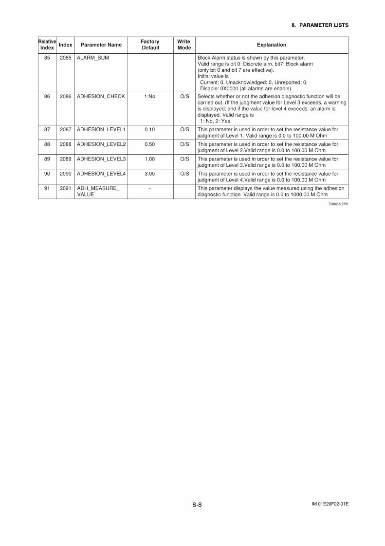
IM 01E20F02-01E8-8
8. PARAMETER LISTS
T0802-5.EPS
Write Mode Explanation
Factory Default
RelativeIndex Parameter NameIndex
Block Alarm status is shown by this parameter. Valid range is bit 0: Discrete alm, bit7: Block alarm (only bit 0 and bit 7 are effective). Initial value is Current: 0, Unacknowledged: 0, Unreported: 0, Disable: 0X0000 (all alarms are enable).
Selects whether or not the adhesion diagnostic function will be carried out. (If the judgment value for Level 3 exceeds, a warning is displayed; and if the value for level 4 exceeds, an alarm is displayed. Valid range is 1: No, 2: Yes
This parameter is used in order to set the resistance value for judgment of Level 1. Valid range is 0.0 to 100.00 M Ohm
This parameter is used in order to set the resistance value for judgment of Level 2.Valid range is 0.0 to 100.00 M Ohm
This parameter is used in order to set the resistance value for judgment of Level 3.Valid range is 0.0 to 100.00 M Ohm
This parameter is used in order to set the resistance value for judgment of Level 4.Valid range is 0.0 to 100.00 M Ohm
This parameter displays the value measured using the adhesion diagnostic function. Valid range is 0.0 to 1000.00 M Ohm
85 2085 ALARM_SUM
86 2086 ADHESION_CHECK 1:No O/S
87 2087 ADHESION_LEVEL1 0.10 O/S
88 2088 ADHESION_LEVEL2 0.50 O/S
89 2089 ADHESION_LEVEL3 1.00 O/S
90 2090 ADHESION_LEVEL4 3.00 O/S
91 2091 - ADH_MEASURE_VALUE
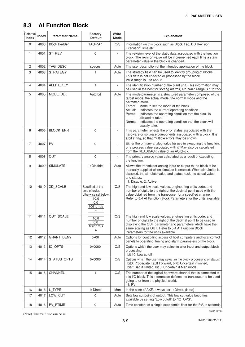
IM 01E20F02-01E8-9
8. PARAMETER LISTS
8.3 AI Function Block
T0803-1.EPS
Write Mode Explanation
Factory Default
RelativeIndex Parameter NameIndex
Information on this block such as Block Tag, DD Revision, Execution Time etc.
The revision level of the static data associated with the function block. The revision value will be incremented each time a static parameter value in the block is changed.
The user description of the intended application of the block
The strategy field can be used to identify grouping of blocks. This data is not checked or processed by the block. Valid range is 0 to 65535.
The identification number of the plant unit. This information may be used in the host for sorting alarms, etc. Valid range is 1 to 255
The mode parameter is a structured parameter composed of the target mode, the actual mode, the normal mode and the permitted mode.Target: Mode to set the mode of the blockActual: Indicates the current operating condition.Permit: Indicates the operating condition that the block is allowed to take.Normal: Indicates the operating condition that the block will usually take.This parameter reflects the error status associated with the hardware or software components associated with a block. It is a bit string, so that multiple errors may be shown.
Either the primary analog value for use in executing the function, or a process value associated with it. May also be calculated from the READBACK value of an AO block.
The primary analog value calculated as a result of executing the function.
Allows the transducer analog input or output to the block to be manually supplied when simulate is enabled. When simulation is disabled, the simulate value and status track the actual value and status. 1: Disable, 2: Active
The high and low scale values, engineering units code, and number of digits to the right of the decimal point used with the value obtained from the transducer for a specified channel. Refer to 5.4 AI Function Block Parameters for the units available.
The high and low scale values, engineering units code, and number of digits to the right of the decimal point to be used in displaying the OUT parameter and parameters which have the same scaling as OUT. Refer to 5.4 AI Function Block Parameters for the units available.
Options for controlling access of host computers and local control panels to operating, tuning and alarm parameters of the block.
Options which the user may select to alter input and output block processing.bit 10: Low cutoff
Options which the user may select in the block processing of status.bit3: Propagate Fault Forward, bit6: Uncertain if limited, bit7: Bad if limited, bit 8: Uncertain if Man mode.
The number of the logical hardware channel that is connected to this I/O block. This information defines the transducer to be used going to or from the physical world.1: PV
In the case of AXF, always set 1: Direct. (Note)
Sets low cut point of output. This low cut value becomes available by setting "Low cutoff" to "IO_OPS".
1 4001 ST_REV 0 -
3 4003 STRATEGY 1 Auto
4 4004 ALERT_KEY 1 -
5 4005 MODE_BLK Auto bit Auto
6 4006 BLOCK_ERR 0 -
7 4007 PV 0 -
8 4008 OUT 0 -
9 4009 SIMULATE 1: Disable Auto
10 4010 XD_SCALE O/S
13 4013 IO_OPTS 0x0000 O/S
14 4014 STATUS_OPTS 0x0000 O/S
15 4015 CHANNEL 1 O/S
16 4016 L_TYPE 1: Direct Man
17 4017 LOW_CUT 0 Auto
Time constant of a single exponential filter for the PV, in seconds. 18 4018 PV_FTIME 0 Auto
11 4011 OUT_SCALE O/S
12 4012 GRANT_DENY 0x00 Auto
2 4002 TAG_DESC spaces Auto
0 4000 Block Hedder TAG="AI" O/S
Specified at the time of order, otherwise set below.
10.00.0
1061: m/s4
10.00.0
1061: m/s4
(Note) "Indirect" also can be set.
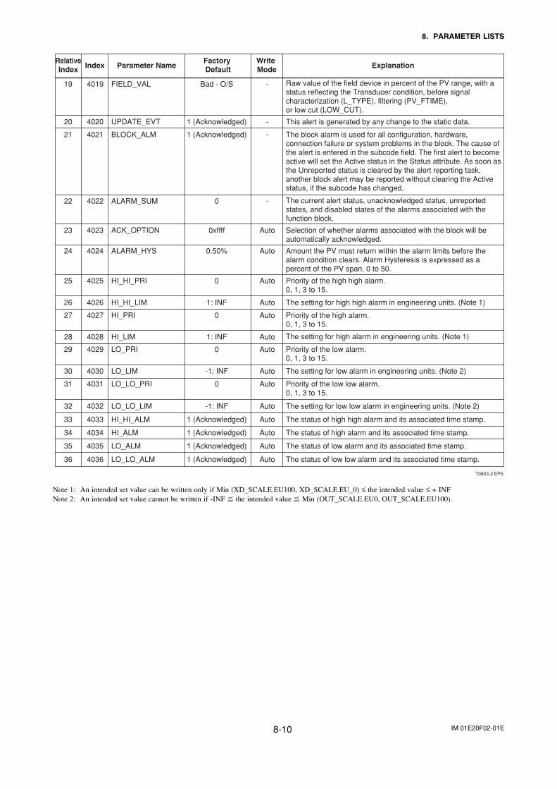
IM 01E20F02-01E8-10
8. PARAMETER LISTS
T0803-2.EPS
Write Mode Explanation
Factory Default
RelativeIndex Parameter NameIndex
Raw value of the field device in percent of the PV range, with a status reflecting the Transducer condition, before signal characterization (L_TYPE), filtering (PV_FTIME), or low cut (LOW_CUT).
This alert is generated by any change to the static data.
The block alarm is used for all configuration, hardware, connection failure or system problems in the block. The cause of the alert is entered in the subcode field. The first alert to become active will set the Active status in the Status attribute. As soon as the Unreported status is cleared by the alert reporting task, another block alert may be reported without clearing the Active status, if the subcode has changed.
The current alert status, unacknowledged status, unreported states, and disabled states of the alarms associated with the function block.
Selection of whether alarms associated with the block will be automatically acknowledged.
Amount the PV must return within the alarm limits before the alarm condition clears. Alarm Hysteresis is expressed as a percent of the PV span. 0 to 50.
Priority of the high high alarm.0, 1, 3 to 15.
The setting for high high alarm in engineering units. (Note 1)
Priority of the high alarm.0, 1, 3 to 15.
The setting for high alarm in engineering units. (Note 1)
Priority of the low alarm.0, 1, 3 to 15.
The setting for low alarm in engineering units. (Note 2)
Priority of the low low alarm.0, 1, 3 to 15.
The setting for low low alarm in engineering units. (Note 2)
The status of high high alarm and its associated time stamp.
The status of high alarm and its associated time stamp.
The status of low alarm and its associated time stamp.
The status of low low alarm and its associated time stamp.
20 4020 UPDATE_EVT 1 (Acknowledged) -
22 4022 ALARM_SUM 0 -
23 4023 ACK_OPTION 0xffff Auto
24 4024 ALARM_HYS 0.50% Auto
25 4025 HI_HI_PRI 0 Auto
26 4026 HI_HI_LIM 1: INF Auto
27 4027 HI_PRI 0 Auto
28 4028 HI_LIM 1: INF Auto
29 4029 LO_PRI 0 Auto
32 4032 LO_LO_LIM -1: INF Auto
33 4033 HI_HI_ALM 1 (Acknowledged) Auto
34 4034 HI_ALM 1 (Acknowledged) Auto
35 4035 LO_ALM 1 (Acknowledged) Auto
36 4036 LO_LO_ALM 1 (Acknowledged) Auto
30 4030 LO_LIM -1: INF Auto
31 4031 LO_LO_PRI 0 Auto
21 4021 BLOCK_ALM 1 (Acknowledged) -
19 4019 FIELD_VAL Bad - O/S -
Note 1: An intended set value can be written only if Min (XD_SCALE.EU100, XD_SCALE.EU_0) ≤ the intended value ≤ + INFNote 2: An intended set value cannot be written if -INF � the intended value � Min (OUT_SCALE.EU0, OUT_SCALE.EU100).
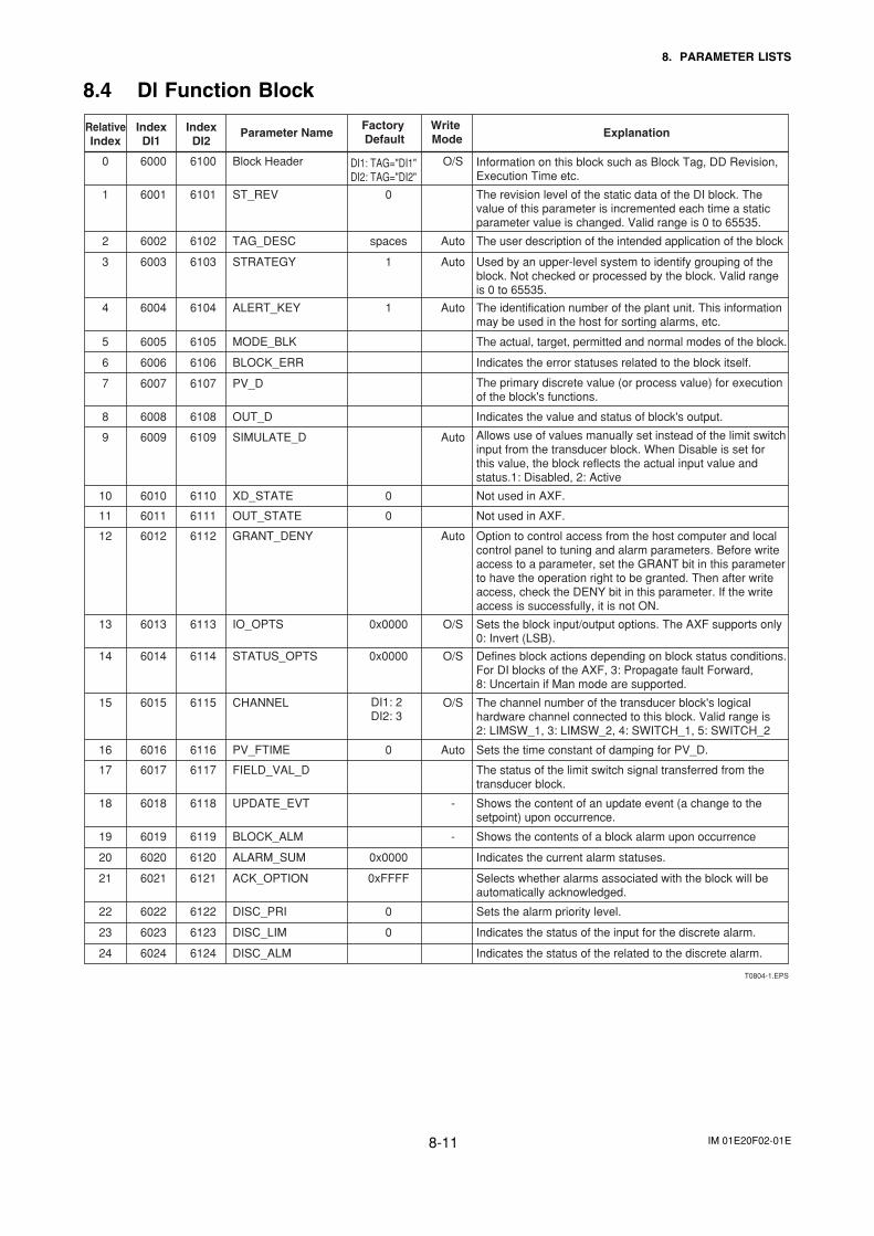
IM 01E20F02-01E8-11
8. PARAMETER LISTS
8.4 Dl Function Block
T0804-1.EPS
Write Mode Explanation
Factory Default
RelativeIndex
Parameter NameIndexDI1
IndexDI2
Information on this block such as Block Tag, DD Revision, Execution Time etc.
The revision level of the static data of the DI block. The value of this parameter is incremented each time a static parameter value is changed. Valid range is 0 to 65535.
The user description of the intended application of the block
Used by an upper-level system to identify grouping of the block. Not checked or processed by the block. Valid range is 0 to 65535.
The identification number of the plant unit. This information may be used in the host for sorting alarms, etc.
The actual, target, permitted and normal modes of the block.
Indicates the error statuses related to the block itself.
The primary discrete value (or process value) for execution of the block's functions.
Indicates the value and status of block's output.
Allows use of values manually set instead of the limit switch input from the transducer block. When Disable is set for this value, the block reflects the actual input value and status. 1: Disabled, 2: Active
Not used in AXF.
Not used in AXF.
Option to control access from the host computer and local control panel to tuning and alarm parameters. Before write access to a parameter, set the GRANT bit in this parameter to have the operation right to be granted. Then after write access, check the DENY bit in this parameter. If the write access is successfully, it is not ON.
Sets the block input/output options. The AXF supports only 0: Invert (LSB).
Defines block actions depending on block status conditions. For DI blocks of the AXF, 3: Propagate fault Forward, 8: Uncertain if Man mode are supported.
The channel number of the transducer block's logical hardware channel connected to this block. Valid range is 2: LIMSW_1, 3: LIMSW_2, 4: SWITCH_1, 5: SWITCH_2
Sets the time constant of damping for PV_D.
The status of the limit switch signal transferred from the transducer block.
1 6001 6101 ST_REV 0
0 6000 6100 Block Header O/S
3 6003 6103 STRATEGY 1 Auto
4 6004 6104 ALERT_KEY 1 Auto
5 6005 6105 MODE_BLK
6 6006 6106 BLOCK_ERR
7 6007 6107 PV_D
8 6008 6108 OUT_D
9 6009 6109 SIMULATE_D Auto
10 6010 6110 XD_STATE 0
13 6013 6113 IO_OPTS 0x0000 O/S
14 6014 6114 STATUS_OPTS 0x0000 O/S
15 6015 6115 CHANNEL O/S
16 6016 6116 PV_FTIME 0 Auto
17 6017 6117 FIELD_VAL_D
Shows the content of an update event (a change to the setpoint) upon occurrence.
18 6018 6118 UPDATE_EVT -
Shows the contents of a block alarm upon occurrence 19 6019 6119 BLOCK_ALM -
Indicates the current alarm statuses. 20 6020 6120 ALARM_SUM 0x0000
Selects whether alarms associated with the block will be automatically acknowledged.
21 6021 6121 ACK_OPTION 0xFFFF
Sets the alarm priority level. 22 6022 6122 DISC_PRI 0
Indicates the status of the input for the discrete alarm. 23 6023 6123 DISC_LIM 0
Indicates the status of the related to the discrete alarm. 24 6024 6124 DISC_ALM
11 6011 6111 OUT_STATE 0
12 6012 6112 GRANT_DENY Auto
2 6002 6102 TAG_DESC spaces Auto
DI1: TAG="DI1"DI2: TAG="DI2"
DI1: 2DI2: 3
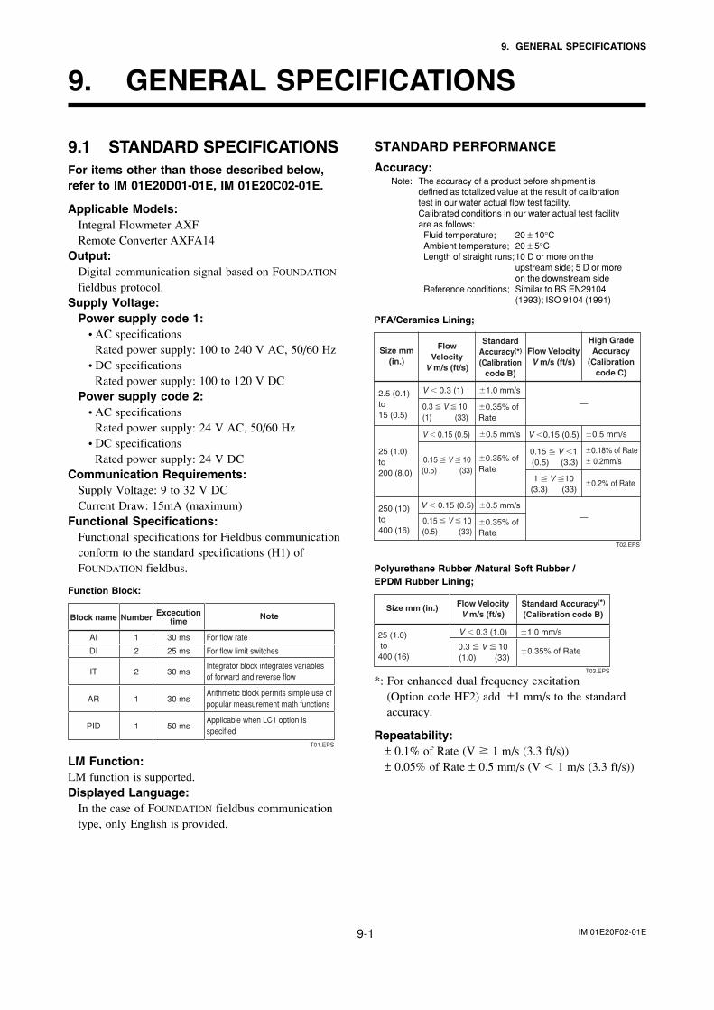
IM 01E20F02-01E9-1
9. GENERAL SPECIFICATIONS
9. GENERAL SPECIFICATIONS
9.1 STANDARD SPECIFICATIONSFor items other than those described below,refer to IM 01E20D01-01E, IM 01E20C02-01E.
Applicable Models:Integral Flowmeter AXFRemote Converter AXFA14
Output:Digital communication signal based on FOUNDATION
fieldbus protocol.Supply Voltage:
Power supply code 1:• AC specifications
Rated power supply: 100 to 240 V AC, 50/60 Hz• DC specifications
Rated power supply: 100 to 120 V DCPower supply code 2:
• AC specificationsRated power supply: 24 V AC, 50/60 Hz
• DC specificationsRated power supply: 24 V DC
Communication Requirements:Supply Voltage: 9 to 32 V DCCurrent Draw: 15mA (maximum)
Functional Specifications:Functional specifications for Fieldbus communicationconform to the standard specifications (H1) ofFOUNDATION fieldbus.
Function Block:
Block name
AI
DI
IT
AR
PID
Number
1
2
2
1
1
Excecutiontime
30 ms
25 ms
30 ms
30 ms
50 ms
Note
For flow rate
For flow limit switches
Integrator block integrates variables of forward and reverse flow
Arithmetic block permits simple use of
popular measurement math functions
Applicable when LC1 option is
specified
T01.EPS
LM Function:LM function is supported.Displayed Language:
In the case of FOUNDATION fieldbus communicationtype, only English is provided.
STANDARD PERFORMANCE
Accuracy:Note: The accuracy of a product before shipment is
defined as totalized value at the result of calibrationtest in our water actual flow test facility.Calibrated conditions in our water actual test facilityare as follows:
Fluid temperature; 20 ± 10°CAmbient temperature; 20 ± 5°CLength of straight runs;10 D or more on the
upstream side; 5 D or moreon the downstream side
Reference conditions; Similar to BS EN29104(1993); ISO 9104 (1991)
PFA/Ceramics Lining;
Size mm (in.)
V � 0.3 (1) �1.0 mm/s
�0.5 mm/s �0.5 mm/s
0.3 � V � 10(1) (33)
V � 0.15 (0.5)
V � 0.15 (0.5)
0.15 � V � 10(0.5) (33)
0.15 � V � 10(0.5) (33)
V �0.15 (0.5)
0.15 � V �1 (0.5) (3.3)
1 � V �10(3.3) (33)
�0.35% of Rate
�0.5 mm/s
�0.35% of Rate
�0.35% of Rate
2.5 (0.1) to 15 (0.5)
250 (10) to 400 (16)
25 (1.0) to 200 (8.0)
—
—
Flow Velocity
V m/s (ft/s)
Flow VelocityV m/s (ft/s)
Standard Accuracy(*) (Calibration
code B)
High Grade Accuracy
(Calibration code C)
�0.18% of Rate � 0.2mm/s
�0.2% of Rate
T02.EPS
Polyurethane Rubber /Natural Soft Rubber /EPDM Rubber Lining;
T03.EPS
Size mm (in.)
V � 0.3 (1.0) �1.0 mm/s
0.3 � V � 10 (1.0) (33)
�0.35% of Rate
25 (1.0) to 400 (16)
Flow VelocityV m/s (ft/s)
Standard Accuracy(*)
(Calibration code B)
*: For enhanced dual frequency excitation(Option code HF2) add ±1 mm/s to the standardaccuracy.
Repeatability:± 0.1% of Rate (V � 1 m/s (3.3 ft/s))± 0.05% of Rate ± 0.5 mm/s (V � 1 m/s (3.3 ft/s))
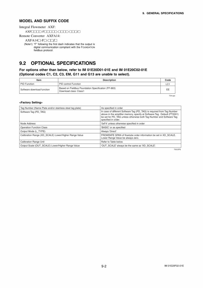
IM 01E20F02-01E9-2
9. GENERAL SPECIFICATIONS
MODEL AND SUFFIX CODE
Integral Flowmeter AXF:AXF����-F�����-����-���/�
Remote Converter AXFA14:AXFA14�-F�-��/�
(Note1) “F” following the first dash indicates that the output isdigital communication compliant with the FOUNDATION
fieldbus protocol.
9.2 OPTIONAL SPECIFICATIONSFor options other than below, refer to IM 01E20D01-01E and IM 01E20C02-01E(Optional codes C1, C2, C3, EM, G11 and G13 are unable to select).
T04.eps
PID control Function
Based on Fieldbus Foundation Specification (FF-883) Download class: Class1
Description CodeItem
LC1
EE
PID Function
Software download function
<Factory Setting>
As specified in orderIn case of different Software Tag (PD_TAG) is required from Tag Number above in the amplifier memory, specify at Software Tag. Default (FT2001) be set for PD_TAG unless otherwise both Tag Number and Software Tag specified in order.
'0xF4' unless otherwise specified in order
'BASIC' or as specified
Always 'Direct'
FROWRATE SPAN of flowtube order information be set in XD_SCALE. Lower Range Value be always zero.
Refer to Table below.
'OUT_SCALE' always be the same as 'XD_SCALE'.
Tag Number (Name Plate and/or stainless steel tag plate)
Software Tag (PD_TAG)
Node Address
Operation Function Class
Output Mode (L_TYPE)
Calibration Range (XD_SCALE) Lower/Higher Range Value
Calibration Range Unit
Output Scale (OUT_SCALE) Lower/Higher Range Value
T05.EPS
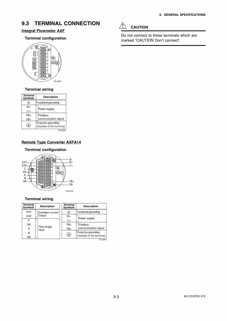
IM 01E20F02-01E9-3
9. GENERAL SPECIFICATIONS
9.3 TERMINAL CONNECTIONIntegral Flowmeter AXF
Terminal configuration
F01.EPS
+
SU
PP
LYF
BP
OW
ER
L/+
N/-
-
Terminal wiring
T06.EPS
TerminalSymbols Description
Protective grounding(Outside of the terminal)
Power supply
Fieldbuscommunication signal
Functional grounding
N/–
L/+
FB+
FB–
Remote Type Converter AXFA14
Terminal configuration
SBBA
SAC
EX2EX1
FB-FB+
L/+N/-
F02.EPS
Terminal wiring
T07.EPS
TerminalSymbols
EX1
EX2
C
SA
A
B
SB
Description
Flow singal input
Excitation current Output
TerminalSymbols Description
Protective grounding(Outside of the terminal)
Power supply
Fieldbuscommunication signal
Functional grounding
N/–
L/+
FB+
FB–
CAUTION
Do not connect to these terminals which aremarked “CAUTION Don’t connect”.

IM 01E20F02-01E10-1
10. MAINTENANCE
10. MAINTENANCE
For maintenance items, please refer to user’smanual IM 01E20D01-01E or IM 01E20C02-01E.
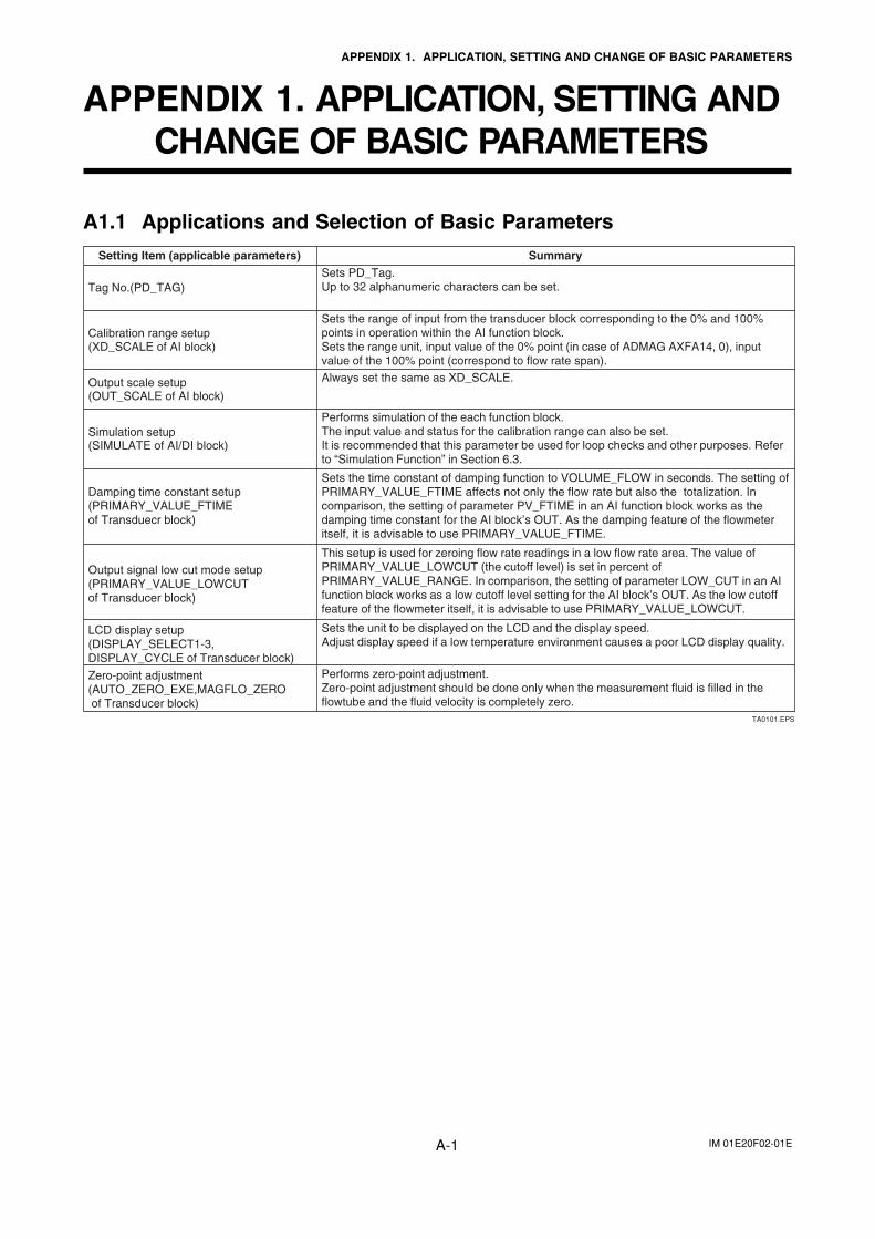
IM 01E20F02-01EA-1
APPENDIX 1. APPLICATION, SETTING AND CHANGE OF BASIC PARAMETERS
APPENDIX 1. APPLICATION, SETTING ANDCHANGE OF BASIC PARAMETERS
A1.1 Applications and Selection of Basic Parameters
Summary
Tag No.(PD_TAG)
Calibration range setup(XD_SCALE of AI block)
Output scale setup(OUT_SCALE of AI block)
Simulation setup(SIMULATE of AI/DI block)
LCD display setup(DISPLAY_SELECT1-3, DISPLAY_CYCLE of Transducer block)
Zero-point adjustment(AUTO_ZERO_EXE,MAGFLO_ZERO of Transducer block)
TA0101.EPS
Setting Item (applicable parameters)
Sets the range of input from the transducer block corresponding to the 0% and 100% points in operation within the AI function block.Sets the range unit, input value of the 0% point (in case of ADMAG AXFA14, 0), input value of the 100% point (correspond to flow rate span).
Performs simulation of the each function block.The input value and status for the calibration range can also be set.It is recommended that this parameter be used for loop checks and other purposes. Refer to “Simulation Function” in Section 6.3.
This setup is used for zeroing flow rate readings in a low flow rate area. The value of PRIMARY_VALUE_LOWCUT (the cutoff level) is set in percent of PRIMARY_VALUE_RANGE. In comparison, the setting of parameter LOW_CUT in an AI function block works as a low cutoff level setting for the AI block’s OUT. As the low cutoff feature of the flowmeter itself, it is advisable to use PRIMARY_VALUE_LOWCUT.
Sets PD_Tag.Up to 32 alphanumeric characters can be set.
Sets the unit to be displayed on the LCD and the display speed.Adjust display speed if a low temperature environment causes a poor LCD display quality.
Sets the time constant of damping function to VOLUME_FLOW in seconds. The setting of PRIMARY_VALUE_FTIME affects not only the flow rate but also the totalization. In comparison, the setting of parameter PV_FTIME in an AI function block works as the damping time constant for the AI block’s OUT. As the damping feature of the flowmeter itself, it is advisable to use PRIMARY_VALUE_FTIME.
Performs zero-point adjustment.Zero-point adjustment should be done only when the measurement fluid is filled in the flowtube and the fluid velocity is completely zero.
Always set the same as XD_SCALE.
Damping time constant setup(PRIMARY_VALUE_FTIMEof Transduecr block)
Output signal low cut mode setup(PRIMARY_VALUE_LOWCUTof Transducer block)
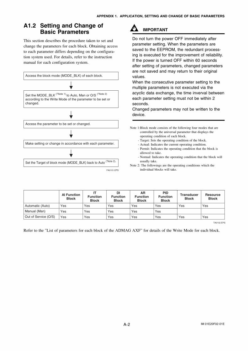
IM 01E20F02-01EA-2
APPENDIX 1. APPLICATION, SETTING AND CHANGE OF BASIC PARAMETERS
A1.2 Setting and Change ofBasic Parameters
This section describes the procedure taken to set andchange the parameters for each block. Obtaining accessto each parameter differs depending on the configura-tion system used. For details, refer to the instructionmanual for each configuration system.
Access the block mode (MODE_BLK) of each block.
Set the MODE_BLK (*Note 1) to Auto, Man or O/S (*Note 2)
according to the Write Mode of the parameter to be set or changed.
FA0101.EPS
Access the parameter to be set or changed.
Make setting or change in accordance with each parameter.
Set the Target of block mode (MODE_BLK) back to Auto (*Note 2).
IMPORTANT
Do not turn the power OFF immediately afterparameter setting. When the parameters aresaved to the EEPROM, the redundant process-ing is executed for the improvement of reliability.If the power is turned OFF within 60 secondsafter setting of parameters, changed parametersare not saved and may return to their originalvalues.When the consecutive parameter setting to themultiple parameters is not executed via theacyclic data exchange, the time inverval betweeneach parameter setting must not be within 2seconds.Changed parameters may not be written to thedevice.
Note 1:Block mode consists of the following four modes that arecontrolled by the universal parameter that displays theoperating condition of each block.
- Target: Sets the operating condition of the block.- Actual: Indicates the current operating condition.- Permit: Indicates the operating condition that the block is
allowed to take.- Normal: Indicates the operating condition that the block will
usually take.Note 2: The followings are the operating conditions which the
individual blocks will take.
AI Function Block
ITFunction
Block
DI Function
Block
ARFunction
Block
PID Function
Block
Automatic (Auto) Yes Yes Yes Yes Yes
Yes YesYes Yes Yes
Yes Yes Yes Yes Yes
Manual (Man)
Out of Service (O/S)
Transducer Block
ResourceBlock
Yes Yes
Yes Yes
TA0102.EPS
Refer to the "List of parameters for each block of the ADMAG AXF" for details of the Write Mode for each block.
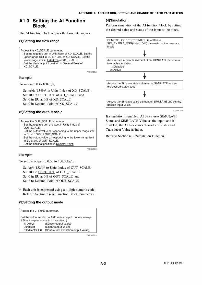
IM 01E20F02-01EA-3
APPENDIX 1. APPLICATION, SETTING AND CHANGE OF BASIC PARAMETERS
A1.3 Setting the AI FunctionBlock
The AI function block outputs the flow rate signals.
(1)Setting the flow range
Access the XD_SCALE parameter. Set the required unit in Unit Index of XD_SCALE. Set the upper range limit in EU at 100% of XD_SCALE. Set the lower range limit in EU at 0% of XD_SCALE. Set the decimal point position in Decimal Point of XD_SCALE.
FA0102.EPS
Example:
To measure 0 to 100m3/h,
Set m3/h (1349)* in Units Index of XD_SCALE,Set 100 in EU at 100% of XD_SCALE, andSet 0 in EU at 0% of XD_SCALE.Set 0 in Decimal Point of XD_SCALE.
(2)Setting the output scale
Access the OUT_SCALE parameter. Set the required unit of output in Units Index of OUT_SCALE. Set the output value corresponding to the upper range limit in EU at 100% of OUT_SCALE. Set the output value corresponding to the lower range limit in EU at 0% of OUT_SCALE. Set the decimal position in Decimal Point.
FA0103.EPS
Example:
To set the output to 0.00 to 100.00kg/h,
Set kg/h(1324)* to Units Index of OUT_SCALE,Set 100 to EU at 100% of OUT_SCALE,Set 0 in EU at 0% of OUT_SCALE, andSet 2 to Decimal Point of OUT_SCALE.
* Each unit is expressed using a 4-digit numeric code.Refer to Section 5.4 AI Function Block Parameters.
(3)Setting the output mode
Access the L_TYPE parameter.
Set the output mode. (In AXF series output mode is always 1:Direct so please confirm the setting.)
1: Direct (Sensor output value) 2:Indirect (Linear output value) 3:IndirectSQRT (Square root extraction output value)
FA0104.EPS
(4)SimulationPerform simulation of the AI function block by settingthe desired value and status of the input to the block.
REMOTE LOOP TEST SWITCH is written to SIM_ENABLE_MSG(index 1044) parameter of the resource block.
Access the En/Disable element of the SIMULATE parameter to enable simulation.
1: Disabled 2: Active
FA0105.EPS
Access the Simulate status element of SIMULATE and set the desired status code.
Access the Simulate value element of SIMULATE and set the desired input value.
If simulation is enabled, AI block uses SIMULATEStatus and SIMULATE Value as the input, and ifdisabled, the AI block uses Transducer Status andTransducer Value as input.
Refer to Section 6.3 "Simulation Function."
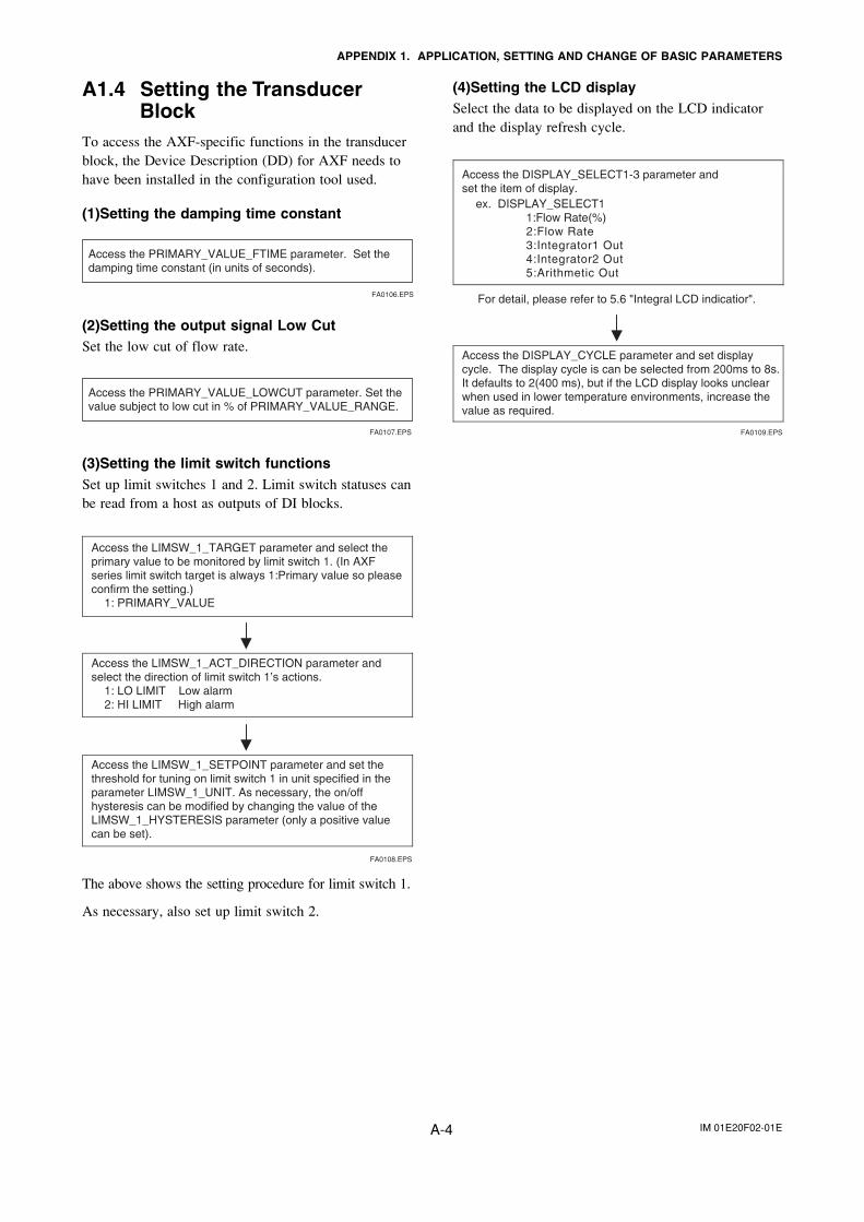
IM 01E20F02-01EA-4
APPENDIX 1. APPLICATION, SETTING AND CHANGE OF BASIC PARAMETERS
A1.4 Setting the TransducerBlock
To access the AXF-specific functions in the transducerblock, the Device Description (DD) for AXF needs tohave been installed in the configuration tool used.
(1)Setting the damping time constant
Access the PRIMARY_VALUE_FTIME parameter. Set the damping time constant (in units of seconds).
FA0106.EPS
(2)Setting the output signal Low CutSet the low cut of flow rate.
Access the PRIMARY_VALUE_LOWCUT parameter. Set the value subject to low cut in % of PRIMARY_VALUE_RANGE.
FA0107.EPS
(3)Setting the limit switch functionsSet up limit switches 1 and 2. Limit switch statuses canbe read from a host as outputs of DI blocks.
Access the LIMSW_1_ACT_DIRECTION parameter and select the direction of limit switch 1’s actions.
1: LO LIMIT Low alarm2: HI LIMIT High alarm
Access the LIMSW_1_SETPOINT parameter and set the threshold for tuning on limit switch 1 in unit specified in the parameter LIMSW_1_UNIT. As necessary, the on/off hysteresis can be modified by changing the value of the LIMSW_1_HYSTERESIS parameter (only a positive value can be set).
Access the LIMSW_1_TARGET parameter and select the primary value to be monitored by limit switch 1. (In AXF series limit switch target is always 1:Primary value so please confirm the setting.)
1: PRIMARY_VALUE
FA0108.EPS
The above shows the setting procedure for limit switch 1.
As necessary, also set up limit switch 2.
(4)Setting the LCD displaySelect the data to be displayed on the LCD indicatorand the display refresh cycle.
ex. DISPLAY_SELECT1 1:Flow Rate(%) 2:Flow Rate3:Integrator1 Out4:Integrator2 Out 5:Arithmetic Out
Access the DISPLAY_CYCLE parameter and set display cycle. The display cycle is can be selected from 200ms to 8s. It defaults to 2(400 ms), but if the LCD display looks unclear when used in lower temperature environments, increase the value as required.
Access the DISPLAY_SELECT1-3 parameter and set the item of display.
FA0109.EPS
For detail, please refer to 5.6 "Integral LCD indicatior".
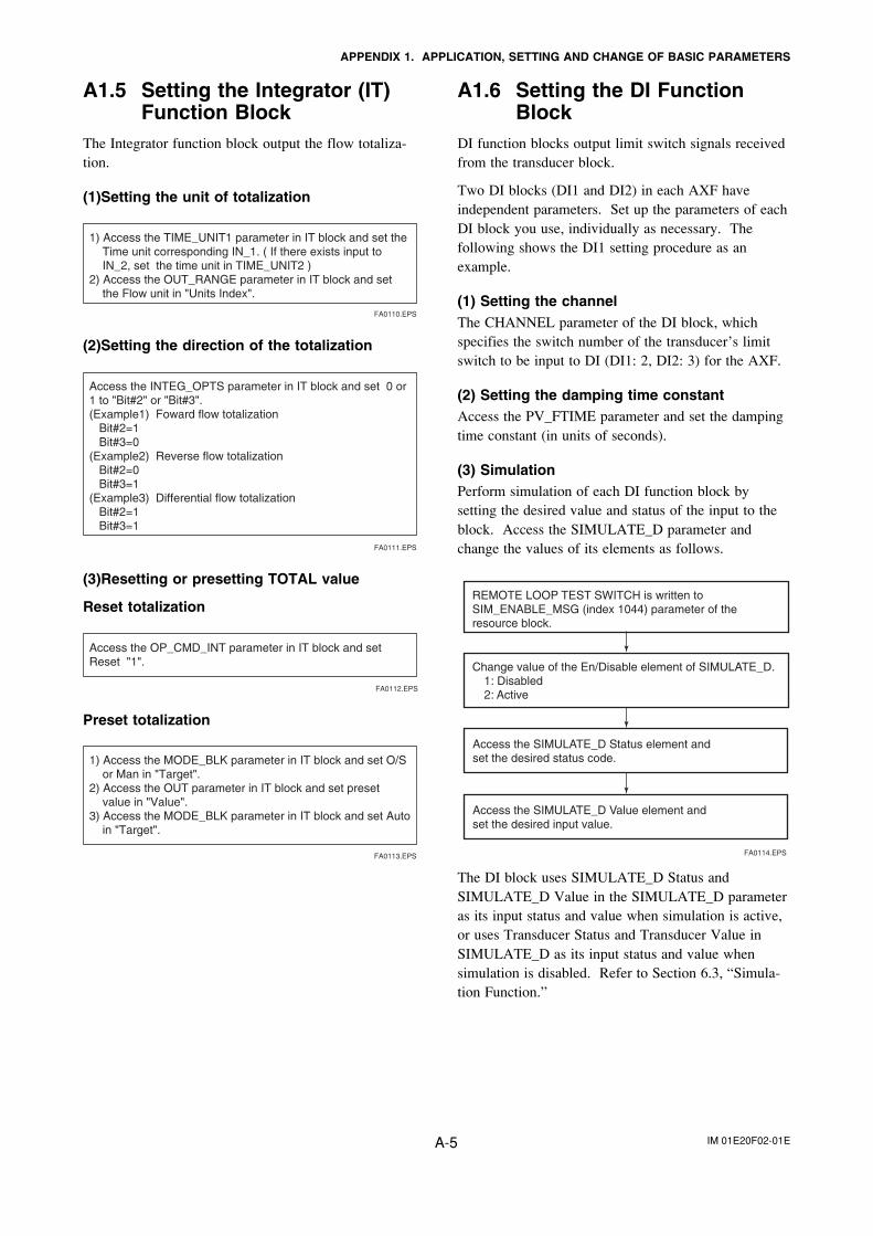
IM 01E20F02-01EA-5
APPENDIX 1. APPLICATION, SETTING AND CHANGE OF BASIC PARAMETERS
A1.5 Setting the Integrator (IT)Function Block
The Integrator function block output the flow totaliza-tion.
(1)Setting the unit of totalization
1) Access the TIME_UNIT1 parameter in IT block and set the Time unit corresponding IN_1. ( If there exists input to IN_2, set the time unit in TIME_UNIT2 )
2) Access the OUT_RANGE parameter in IT block and set the Flow unit in "Units Index".
FA0110.EPS
(2)Setting the direction of the totalization
Access the INTEG_OPTS parameter in IT block and set 0 or 1 to "Bit#2" or "Bit#3". (Example1) Foward flow totalization Bit#2=1 Bit#3=0 (Example2) Reverse flow totalization Bit#2=0 Bit#3=1 (Example3) Differential flow totalization Bit#2=1 Bit#3=1
FA0111.EPS
(3)Resetting or presetting TOTAL value
Reset totalization
Access the OP_CMD_INT parameter in IT block and set Reset "1".
FA0112.EPS
Preset totalization
1) Access the MODE_BLK parameter in IT block and set O/S or Man in "Target".
2) Access the OUT parameter in IT block and set preset value in "Value".
3) Access the MODE_BLK parameter in IT block and set Auto in "Target".
FA0113.EPS
A1.6 Setting the DI FunctionBlock
DI function blocks output limit switch signals receivedfrom the transducer block.
Two DI blocks (DI1 and DI2) in each AXF haveindependent parameters. Set up the parameters of eachDI block you use, individually as necessary. Thefollowing shows the DI1 setting procedure as anexample.
(1) Setting the channelThe CHANNEL parameter of the DI block, whichspecifies the switch number of the transducer’s limitswitch to be input to DI (DI1: 2, DI2: 3) for the AXF.
(2) Setting the damping time constantAccess the PV_FTIME parameter and set the dampingtime constant (in units of seconds).
(3) SimulationPerform simulation of each DI function block bysetting the desired value and status of the input to theblock. Access the SIMULATE_D parameter andchange the values of its elements as follows.
FA0114.EPS
Access the SIMULATE_D Value element and set the desired input value.
Access the SIMULATE_D Status element and set the desired status code.
Change value of the En/Disable element of SIMULATE_D. 1: Disabled 2: Active
REMOTE LOOP TEST SWITCH is written to SIM_ENABLE_MSG (index 1044) parameter of the resource block.
The DI block uses SIMULATE_D Status andSIMULATE_D Value in the SIMULATE_D parameteras its input status and value when simulation is active,or uses Transducer Status and Transducer Value inSIMULATE_D as its input status and value whensimulation is disabled. Refer to Section 6.3, “Simula-tion Function.”
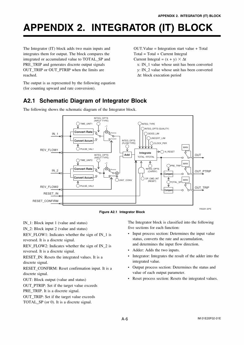
IM 01E20F02-01EA-6
APPENDIX 2. INTEGRATOR (IT) BLOCK
APPENDIX 2. INTEGRATOR (IT) BLOCK
IN_1: Block input 1 (value and status)
IN_2: Block input 2 (value and status)
REV_FLOW1: Indicates whether the sign of IN_1 isreversed. It is a discrete signal.
REV_FLOW2: Indicates whether the sign of IN_2 isreversed. It is a discrete signal.
RESET_IN: Resets the integrated values. It is adiscrete signal.
RESET_CONFIRM: Reset confirmation input. It is adiscrete signal.
OUT: Block output (value and status)
OUT_PTRIP: Set if the target value exceedsPRE_TRIP. It is a discrete signal.
OUT_TRIP: Set if the target value exceedsTOTAL_SP (or 0). It is a discrete signal.
The Integrator (IT) block adds two main inputs andintegrates them for output. The block compares theintegrated or accumulated value to TOTAL_SP andPRE_TRIP and generates discrete output signalsOUT_TRIP or OUT_PTRIP when the limits arereached.
The output is as represented by the following equation(for counting upward and rate conversion).
OUT.Value = Integration start value + TotalTotal = Total + Current IntegralCurrent Integral = (x + y) � ∆t
x: IN_1 value whose unit has been convertedy: IN_2 value whose unit has been converted∆t: block execution period
A2.1 Schematic Diagram of Integrator BlockThe following shows the schematic diagram of the Integrator block.
OUT
IN_1
RESET_IN
REV_FLOW1
–1
TIME_UNIT2
IN_2
REV_FLOW2 PULSE_VAL2
–1
UNIT_CONVOP_CMD_INT
(RESET)
INTEG_OPTS(CARRY)
Reverse
Forward
Forward
OUT_PTRIP
OUT_TRIP
INTEG_OPTS(FLOW TYPE)
Add
Compare
Compare
TOTAL / RTOTAL
Integrate
INTEG_TYPE
INTEG_OPTS (QUALITY)
GOOD_LIM
UNCERT_LIM
CLOCK_PER
N_RESET
MAN
MAN
MAN
Convert Rate
Convert Accum
Convert Rate
Convert Accum
TOTAL_SP
PRE_TRIP
INTEG_OPTS(INPUT TYPE)
PULSE_VAL1
TIME_UNIT1
INTEG_OPTS(INPUT TYPE)
RESET_CONFIRM
Reverse
FA0201.EPS
Figure A2.1 Integrator Block
The Integrator block is classified into the followingfive sections for each function:
• Input process section: Determines the input valuestatus, converts the rate and accumulation,and determines the input flow direction.
• Adder: Adds the two inputs.
• Integrator: Integrates the result of the adder into theintegrated value.
• Output process section: Determines the status andvalue of each output parameter.
• Reset process section: Resets the integrated values.
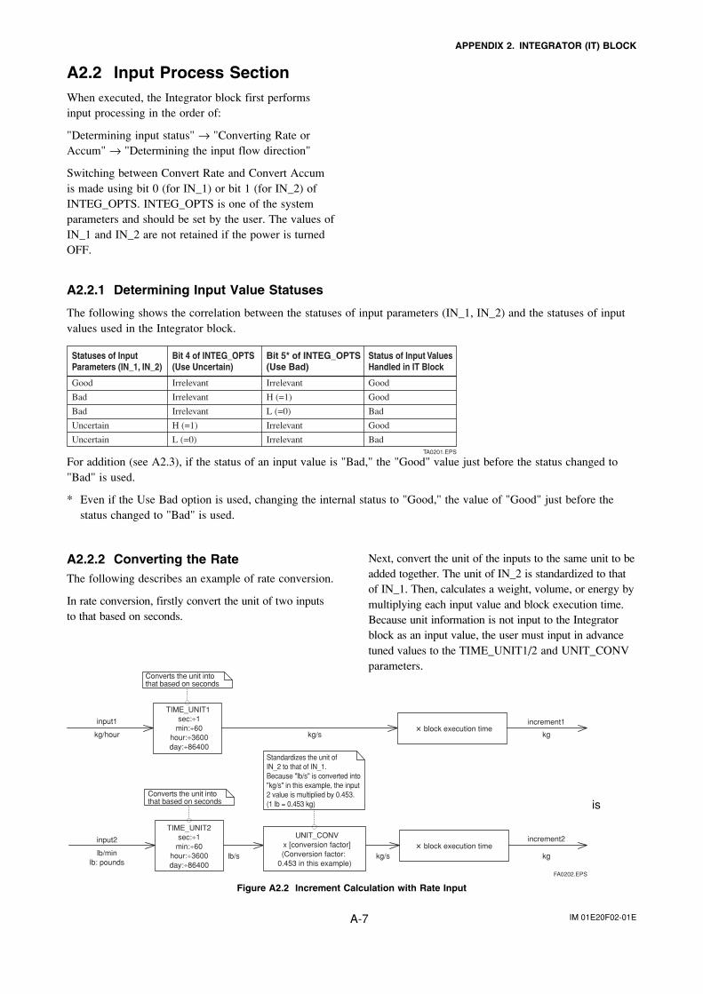
IM 01E20F02-01EA-7
APPENDIX 2. INTEGRATOR (IT) BLOCK
A2.2 Input Process SectionWhen executed, the Integrator block first performsinput processing in the order of:
"Determining input status" → "Converting Rate orAccum" → "Determining the input flow direction"
Switching between Convert Rate and Convert Accumis made using bit 0 (for IN_1) or bit 1 (for IN_2) ofINTEG_OPTS. INTEG_OPTS is one of the systemparameters and should be set by the user. The values ofIN_1 and IN_2 are not retained if the power is turnedOFF.
A2.2.1 Determining Input Value Statuses
The following shows the correlation between the statuses of input parameters (IN_1, IN_2) and the statuses of inputvalues used in the Integrator block.
Statuses of Input Parameters (IN_1, IN_2)
Bit 4 of INTEG_OPTS(Use Uncertain)
Bit 5* of INTEG_OPTS(Use Bad)
Status of Input Values Handled in IT Block
Good Irrelevant Irrelevant Good
Bad Irrelevant H (=1) Good
Bad Irrelevant L (=0) Bad
Uncertain H (=1) Irrelevant Good
Uncertain L (=0) Irrelevant BadTA0201.EPS
For addition (see A2.3), if the status of an input value is "Bad," the "Good" value just before the status changed to"Bad" is used.
* Even if the Use Bad option is used, changing the internal status to "Good," the value of "Good" just before thestatus changed to "Bad" is used.
A2.2.2 Converting the RateThe following describes an example of rate conversion.
In rate conversion, firstly convert the unit of two inputsto that based on seconds.
Next, convert the unit of the inputs to the same unit to beadded together. The unit of IN_2 is standardized to thatof IN_1. Then, calculates a weight, volume, or energy bymultiplying each input value and block execution time.Because unit information is not input to the Integratorblock as an input value, the user must input in advancetuned values to the TIME_UNIT1/2 and UNIT_CONVparameters.
TIME_UNIT1sec:÷1
min:÷60hour:÷3600day:÷86400
input1
kg/hour
input2
lb/s kg/s kg
increment2
increment1
lb/minlb: pounds
Converts the unit into that based on seconds
Standardizes the unit of IN_2 to that of IN_1.Because "lb/s" is converted into "kg/s" in this example, the input 2 value is multiplied by 0.453. (1 lb = 0.453 kg)
UNIT_CONVx [conversion factor](Conversion factor:
0.453 in this example)
Converts the unit into that based on seconds
TIME_UNIT2sec:÷1
min:÷60hour:÷3600day:÷86400
kg/s kg � block execution time
� block execution time
FA0202.EPS
is
Figure A2.2 Increment Calculation with Rate Input
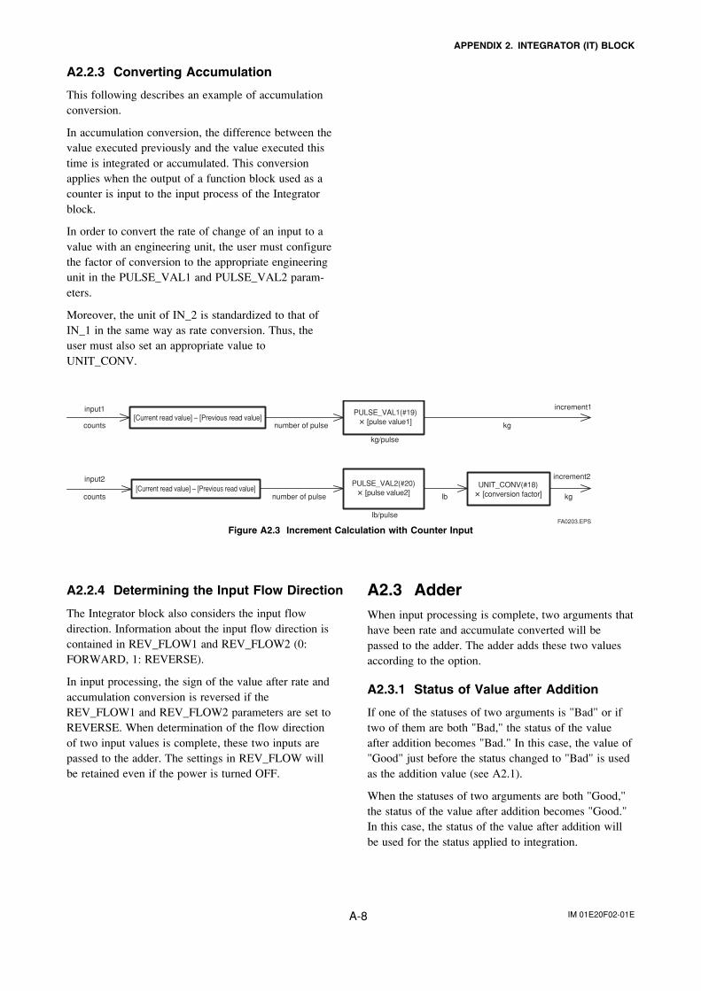
IM 01E20F02-01EA-8
APPENDIX 2. INTEGRATOR (IT) BLOCK
A2.2.3 Converting Accumulation
This following describes an example of accumulationconversion.
In accumulation conversion, the difference between thevalue executed previously and the value executed thistime is integrated or accumulated. This conversionapplies when the output of a function block used as acounter is input to the input process of the Integratorblock.
In order to convert the rate of change of an input to avalue with an engineering unit, the user must configurethe factor of conversion to the appropriate engineeringunit in the PULSE_VAL1 and PULSE_VAL2 param-eters.
Moreover, the unit of IN_2 is standardized to that ofIN_1 in the same way as rate conversion. Thus, theuser must also set an appropriate value toUNIT_CONV.
input1
counts number of pulse kg
kg/pulse
increment1
increment2
lb/pulse
input2
counts number of pulse lb kg
[Current read value] – [Previous read value]
[Current read value] – [Previous read value]
PULSE_VAL1(#19)� [pulse value1]
PULSE_VAL2(#20)� [pulse value2]
UNIT_CONV(#18)� [conversion factor]
FA0203.EPS
Figure A2.3 Increment Calculation with Counter Input
A2.2.4 Determining the Input Flow Direction
The Integrator block also considers the input flowdirection. Information about the input flow direction iscontained in REV_FLOW1 and REV_FLOW2 (0:FORWARD, 1: REVERSE).
In input processing, the sign of the value after rate andaccumulation conversion is reversed if theREV_FLOW1 and REV_FLOW2 parameters are set toREVERSE. When determination of the flow directionof two input values is complete, these two inputs arepassed to the adder. The settings in REV_FLOW willbe retained even if the power is turned OFF.
A2.3 AdderWhen input processing is complete, two arguments thathave been rate and accumulate converted will bepassed to the adder. The adder adds these two valuesaccording to the option.
A2.3.1 Status of Value after Addition
If one of the statuses of two arguments is "Bad" or iftwo of them are both "Bad," the status of the valueafter addition becomes "Bad." In this case, the value of"Good" just before the status changed to "Bad" is usedas the addition value (see A2.1).
When the statuses of two arguments are both "Good,"the status of the value after addition becomes "Good."In this case, the status of the value after addition willbe used for the status applied to integration.
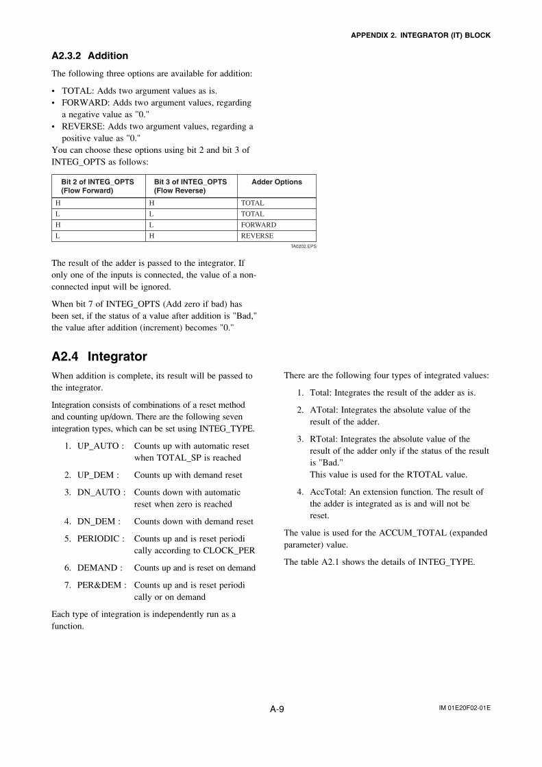
IM 01E20F02-01EA-9
APPENDIX 2. INTEGRATOR (IT) BLOCK
A2.3.2 Addition
The following three options are available for addition:
• TOTAL: Adds two argument values as is.• FORWARD: Adds two argument values, regarding
a negative value as "0."• REVERSE: Adds two argument values, regarding a
positive value as "0."You can choose these options using bit 2 and bit 3 ofINTEG_OPTS as follows:
Bit 2 of INTEG_OPTS (Flow Forward)
Bit 3 of INTEG_OPTS (Flow Reverse)
Adder Options
H H TOTAL
L L TOTAL
H L FORWARD
L H REVERSETA0202.EPS
The result of the adder is passed to the integrator. Ifonly one of the inputs is connected, the value of a non-connected input will be ignored.
When bit 7 of INTEG_OPTS (Add zero if bad) hasbeen set, if the status of a value after addition is "Bad,"the value after addition (increment) becomes "0."
A2.4 IntegratorWhen addition is complete, its result will be passed tothe integrator.
Integration consists of combinations of a reset methodand counting up/down. There are the following sevenintegration types, which can be set using INTEG_TYPE.
1. UP_AUTO : Counts up with automatic resetwhen TOTAL_SP is reached
2. UP_DEM : Counts up with demand reset
3. DN_AUTO : Counts down with automaticreset when zero is reached
4. DN_DEM : Counts down with demand reset
5. PERIODIC : Counts up and is reset periodically according to CLOCK_PER
6. DEMAND : Counts up and is reset on demand
7. PER&DEM : Counts up and is reset periodically or on demand
Each type of integration is independently run as afunction.
There are the following four types of integrated values:
1. Total: Integrates the result of the adder as is.
2. ATotal: Integrates the absolute value of theresult of the adder.
3. RTotal: Integrates the absolute value of theresult of the adder only if the status of the resultis "Bad."This value is used for the RTOTAL value.
4. AccTotal: An extension function. The result ofthe adder is integrated as is and will not bereset.
The value is used for the ACCUM_TOTAL (expandedparameter) value.
The table A2.1 shows the details of INTEG_TYPE.
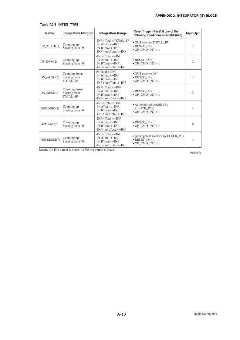
IM 01E20F02-01EA-10
APPENDIX 2. INTEGRATOR (IT) BLOCK
Table A2.1 INTEG_TYPE
Name Integration Method Integration Range Reset Trigger (Reset if one of the following conditions is established) Trip Output
UP_AUTO(1) Counting upStarting from "0"
-INF< Total <TOTAL_SP 0< ATotal <+INF 0< RTotal <+INF-INF< AccTotal <+INF
• OUT reaches TOTAL_SP.• RESET_IN = 1• OP_CMD_INT = 1
�
UP_DEM(2)Counting upStarting from "0"
-INF< Total <+INF 0< ATotal <+INF 0< RTotal <+INF-INF< AccTotal <+INF
• RESET_IN = 1• OP_CMD_INT = 1
�
DN_AUTO(3)Counting downStarting from TOTAL_SP
0< Total <+INF 0< ATotal <+INF 0< RTotal <+INF-INF< AccTotal <+INF
• OUT reaches "0."• RESET_IN = 1• OP_CMD_INT = 1
�
DN_DEM(4)Counting downStarting from TOTAL_SP
-INF< Total <+INF 0< ATotal <+INF 0< RTotal <+INF-INF< AccTotal <+INF
• RESET_IN = 1• OP_CMD_INT = 1
�
PERIODIC(5)Counting upStarting from "0"
-INF< Total <+INF 0< ATotal <+INF 0< RTotal <+INF-INF< AccTotal <+INF
• At the period specified by CLOCK_PER• OP_CMD_INT = 1
�
DEMAND(6)Counting upStarting from "0"
-INF< Total <+INF 0< ATotal <+INF 0< RTotal <+INF-INF< AccTotal <+INF
• RESET_IN = 1• OP_CMD_INT = 1
�
PER&DEM(7)
Legend �: Trip output is made. �: No trip output is made.
Counting upStarting from "0"
-INF< Total <+INF 0< ATotal <+INF 0< RTotal <+INF-INF< AccTotal <+INF
• At the period specified by CLOCK_PER• RESET_IN = 1• OP_CMD_INT = 1
�
TA0203.EPS
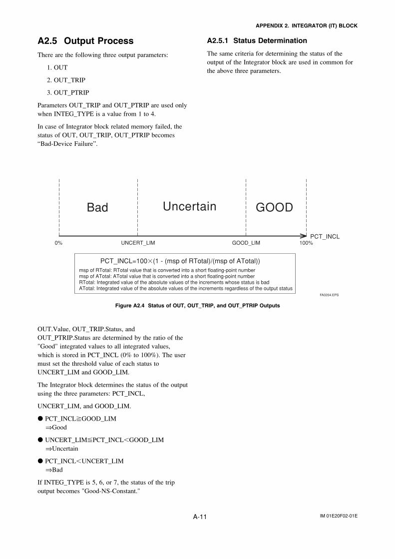
IM 01E20F02-01EA-11
APPENDIX 2. INTEGRATOR (IT) BLOCK
A2.5 Output ProcessThere are the following three output parameters:
1. OUT
2. OUT_TRIP
3. OUT_PTRIP
Parameters OUT_TRIP and OUT_PTRIP are used onlywhen INTEG_TYPE is a value from 1 to 4.
In case of Integrator block related memory failed, thestatus of OUT, OUT_TRIP, OUT_PTRIP becomes“Bad-Device Failure”.
OUT.Value, OUT_TRIP.Status, andOUT_PTRIP.Status are determined by the ratio of the"Good" integrated values to all integrated values,which is stored in PCT_INCL (0% to 100%). The usermust set the threshold value of each status toUNCERT_LIM and GOOD_LIM.
The Integrator block determines the status of the outputusing the three parameters: PCT_INCL,
UNCERT_LIM, and GOOD_LIM.
� PCT_INCL�GOOD_LIM ⇒Good
� UNCERT_LIM�PCT_INCL�GOOD_LIM ⇒Uncertain
� PCT_INCL�UNCERT_LIM ⇒Bad
If INTEG_TYPE is 5, 6, or 7, the status of the tripoutput becomes "Good-NS-Constant."
0% UNCERT_LIM GOOD_LIM 100%PCT_INCL
GOODUncertainBad
PCT_INCL=100�(1 - (msp of RTotal)/(msp of ATotal))msp of RTotal: RTotal value that is converted into a short floating-point numbermsp of ATotal: ATotal value that is converted into a short floating-point numberRTotal: Integrated value of the absolute values of the increments whose status is badATotal: Integrated value of the absolute values of the increments regardless of the output status
FA0204.EPS
Figure A2.4 Status of OUT, OUT_TRIP, and OUT_PTRIP Outputs
A2.5.1 Status Determination
The same criteria for determining the status of theoutput of the Integrator block are used in common forthe above three parameters.
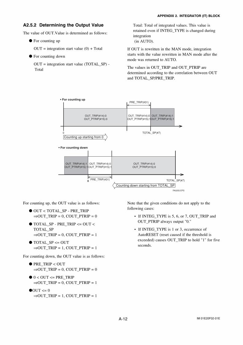
IM 01E20F02-01EA-12
APPENDIX 2. INTEGRATOR (IT) BLOCK
A2.5.2 Determining the Output Value
The value of OUT.Value is determined as follows:
� For counting up
OUT = integration start value (0) + Total
� For counting down
OUT = integration start value (TOTAL_SP) -Total
OUT_TRIP(#14):0OUT_PTRIP(#15):0
OUT_TRIP(#14):1OUT_PTRIP(#15):1
Counting up starting from 0
• For counting upPRE_TRIP(#31)
OUT_TRIP(#14):0OUT_PTRIP(#15):0
OUT_TRIP(#14):0OUT_PTRIP(#15):1
OUT_TRIP(#14):1OUT_PTRIP(#15):1
• For counting down
Counting down starting from TOTAL_SP
PRE_TRIP(#31)0
0 TOTAL_SP(#7)
TOTAL_SP(#7)
FA0205.EPS
OUT_TRIP(#14):0OUT_PTRIP(#15):1
Total: Total of integrated values. This value isretained even if INTEG_TYPE is changed duringintegration (in AUTO).
If OUT is rewritten in the MAN mode, integrationstarts with the value rewritten in MAN mode after themode was returned to AUTO.
The values in OUT_TRIP and OUT_PTRIP aredetermined according to the correlation between OUTand TOTAL_SP/PRE_TRIP.
For counting up, the OUT value is as follows:
� OUT < TOTAL_SP - PRE_TRIP⇒OUT_TRIP = 0, COUT_PTRIP = 0
� TOTAL_SP - PRE_TRIP <= OUT <TOTAL_SP⇒OUT_TRIP = 0, COUT_PTRIP = 1
� TOTAL_SP <= OUT⇒OUT_TRIP = 1, COUT_PTRIP = 1
For counting down, the OUT value is as follows:
� PRE_TRIP < OUT⇒OUT_TRIP = 0, COUT_PTRIP = 0
� 0 < OUT <= PRE_TRIP⇒OUT_TRIP = 0, COUT_PTRIP = 1
�OUT <= 0⇒OUT_TRIP = 1, COUT_PTRIP = 1
Note that the given conditions do not apply to thefollowing cases:
• If INTEG_TYPE is 5, 6, or 7, OUT_TRIP andOUT_PTRIP always output "0."
• If INTEG_TYPE is 1 or 3, occurrence ofAutoRESET (reset caused if the threshold isexceeded) causes OUT_TRIP to hold "1" for fiveseconds.
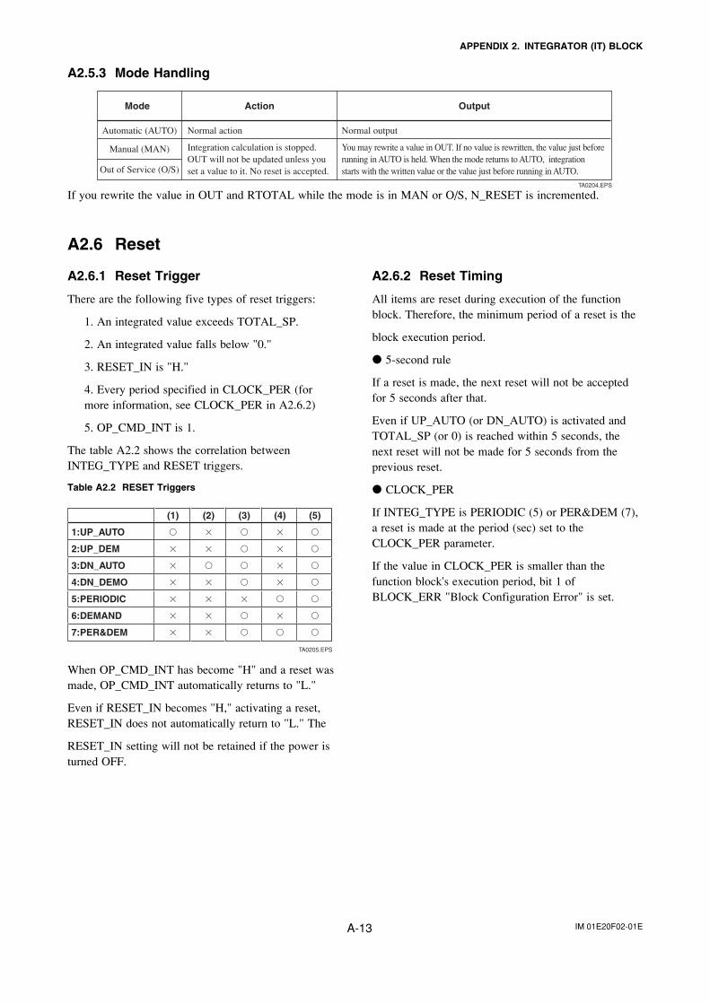
IM 01E20F02-01EA-13
APPENDIX 2. INTEGRATOR (IT) BLOCK
A2.5.3 Mode Handling
Mode Action Output
Normal action Normal output
Integration calculation is stopped. OUT will not be updated unless you set a value to it. No reset is accepted.
You may rewrite a value in OUT. If no value is rewritten, the value just before running in AUTO is held. When the mode returns to AUTO, integration starts with the written value or the value just before running in AUTO.
Automatic (AUTO)
Manual (MAN)
Out of Service (O/S)
TA0204.EPS
If you rewrite the value in OUT and RTOTAL while the mode is in MAN or O/S, N_RESET is incremented.
A2.6.2 Reset Timing
All items are reset during execution of the functionblock. Therefore, the minimum period of a reset is the
block execution period.
� 5-second rule
If a reset is made, the next reset will not be acceptedfor 5 seconds after that.
Even if UP_AUTO (or DN_AUTO) is activated andTOTAL_SP (or 0) is reached within 5 seconds, thenext reset will not be made for 5 seconds from theprevious reset.
� CLOCK_PER
If INTEG_TYPE is PERIODIC (5) or PER&DEM (7),a reset is made at the period (sec) set to theCLOCK_PER parameter.
If the value in CLOCK_PER is smaller than thefunction block's execution period, bit 1 ofBLOCK_ERR "Block Configuration Error" is set.
A2.6 Reset
A2.6.1 Reset Trigger
There are the following five types of reset triggers:
1. An integrated value exceeds TOTAL_SP.
2. An integrated value falls below "0."
3. RESET_IN is "H."
4. Every period specified in CLOCK_PER (formore information, see CLOCK_PER in A2.6.2)
5. OP_CMD_INT is 1.
The table A2.2 shows the correlation betweenINTEG_TYPE and RESET triggers.
Table A2.2 RESET Triggers
(1) (2) (3) (4) (5)
1:UP_AUTO � � � � �
2:UP_DEM � � � � �
3:DN_AUTO � � � � �
4:DN_DEMO � � � � �
5:PERIODIC � � � � �
6:DEMAND � � � � �
7:PER&DEM � � � � �
TA0205.EPS
When OP_CMD_INT has become "H" and a reset wasmade, OP_CMD_INT automatically returns to "L."
Even if RESET_IN becomes "H," activating a reset,RESET_IN does not automatically return to "L." The
RESET_IN setting will not be retained if the power isturned OFF.
IM 01E20F02-01EA-14
APPENDIX 2. INTEGRATOR (IT) BLOCK
A2.6.3 Reset Process
The basic reset process sequence is as follows:
1.) Snapshot
2.) Clearing the integrated values
3.) Reset count increment
4.) Judging OUT_TRIP and OUT_PTRIP (seeA2.5)
1.) Snapshot
Saves the following values in the specified parametersbefore clearing the integrated values. These values willbe retained until the next reset is made.
STOTAL = Total
SRTOTAL = RTotal
SSP = TOTAL_SP
2.) Clearing the integrated values
The reset process clears the Total, ATotal, and RTotalvalues in the internal registers.
Total = 0
ATotal = 0
RTotal = 0
3.) Reset count increment
Each time a reset is made, the N_RESET parameterwill be incremented.
The high limit is 999,999, and if this limit is exceeded,the count returns to "0."
4.) Judging OUT_TRIP and OUT_PTRIP (see A2.5)
OUT_TRIP and OUT_PTRIP are judged again on thebasis of the cleared integrated values.
There are three options relating to a reset:
i Confirm reset (bit 8 of INTEG_OPTS)
ii Carry (bit 6 of INTEG_OPTS)
iii Generate reset event (bit 9 of INTEG_OPTS)
i Confirm reset (bit 8 of INTEG_OPTS)
If this option is enabled, the next reset is rejecteduntil "1" is set to RESET_CONFIRM.
ii Carry (bit 6 of INTEG_OPTS)
If this option is enabled while INTEG_TYPE isUP_AUTO or DN_AUTO, the value exceeding thethreshold at a reset will be carried into the nextintegration.
If INTEG_TYPE is any setting other thanUP_AUTO or DN_AUTO, this option is irrelevant.
iii Generate reset event (bit 9 of INTEG_OPTS)
If this option is enabled, an alert event is generatedif a reset occurs.
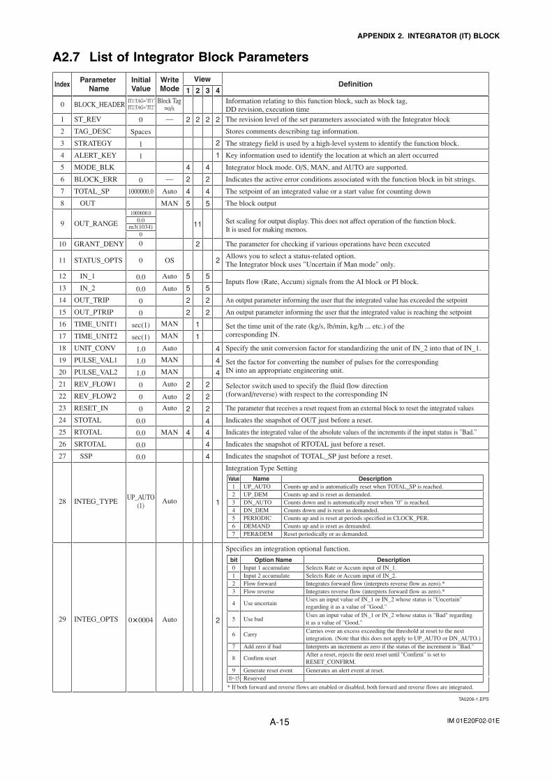
IM 01E20F02-01EA-15
APPENDIX 2. INTEGRATOR (IT) BLOCK
A2.7 List of Integrator Block Parameters
TA0206-1.EPS
Index Parameter Name
InitialValue
WriteMode
Definition
OUT
IN_1
IN_2
SSP
0
1
2
3
4
5
6
7
8
9
10
11
12
13
14
15
16
17
18
19
20
21
22
23
24
25
26
27
28
29
0 2 2 2 2
1 2 3 4
2
1
4 4
2 2
4 4
5 5
2
11
2
5 5
5 5
2 2
2 2
1
1
4
4
4
2 2
2 2
2 2
4
4 4
4
4
1
2
Spaces
1
1
0
1000000.0
1000000.00.0
m3(1034)0
0
0
0.0
0.0
0
0
sec(1)
sec(1)
1.0
1.0
1.0
0
0
0
0.0
0.0
0.0
0.0
UP_AUTO(1)
0�0004
Block Tag=o/s
MAN
OS
MAN
MAN
MAN
MAN
MAN
—
—
Auto
Auto
Auto
Auto
Auto
Auto
Auto
Auto
Auto
View
BLOCK_HEADER
ST_REV
TAG_DESC
STRATEGY
ALERT_KEY
MODE_BLK
BLOCK_ERR
TOTAL_SP
OUT_RANGE
GRANT_DENY
STATUS_OPTS
OUT_TRIP
OUT_PTRIP
TIME_UNIT1
TIME_UNIT2
UNIT_CONV
PULSE_VAL1
PULSE_VAL2
REV_FLOW1
REV_FLOW2
RESET_IN
STOTAL
RTOTAL
SRTOTAL
INTEG_TYPE
INTEG_OPTS
Information relating to this function block, such as block tag, DD revision, execution timeThe revision level of the set parameters associated with the Integrator block
Stores comments describing tag information.
The strategy field is used by a high-level system to identify the function block.
Key information used to identify the location at which an alert occurred
Integrator block mode. O/S, MAN, and AUTO are supported.
Indicates the active error conditions associated with the function block in bit strings.
The setpoint of an integrated value or a start value for counting down
The block output
Set scaling for output display. This does not affect operation of the function block. It is used for making memos.
The parameter for checking if various operations have been executed
Allows you to select a status-related option.The Integrator block uses "Uncertain if Man mode" only.
Inputs flow (Rate, Accum) signals from the AI block or PI block.
An output parameter informing the user that the integrated value has exceeded the setpoint
An output parameter informing the user that the integrated value is reaching the setpoint
Set the time unit of the rate (kg/s, lb/min, kg/h ... etc.) of the corresponding IN.
Set the factor for converting the number of pulses for the corresponding IN into an appropriate engineering unit.
Selector switch used to specify the fluid flow direction (forward/reverse) with respect to the corresponding IN
The parameter that receives a reset request from an external block to reset the integrated values
Indicates the snapshot of OUT just before a reset.
Indicates the integrated value of the absolute values of the increments if the input status is "Bad."
Indicates the snapshot of RTOTAL just before a reset.
Indicates the snapshot of TOTAL_SP just before a reset.
Integration Type Setting
Specifies an integration optional function.
Value Name Description1 UP_AUTO Counts up and is automatically reset when TOTAL_SP is reached.2 UP_DEM Counts up and is reset as demanded.3 DN_AUTO Counts down and is automatically reset when "0" is reached.4 DN_DEM Counts down and is reset as demanded.5 PERIODIC Counts up and is reset at periods specified in CLOCK_PER.6 DEMAND Counts up and is reset as demanded.7 PER&DEM Reset periodically or as demanded.
bit Option Name Description0 Input 1 accumulate Selects Rate or Accum input of IN_1.1 Input 2 accumulate Selects Rate or Accum input of IN_2.2 Flow forward Integrates forward flow (interprets reverse flow as zero).*3 Flow reverse Integrates reverse flow (interprets forward flow as zero).*
4 Use uncertainUses an input value of IN_1 or IN_2 whose status is "Uncertain" regarding it as a value of "Good."
7 Add zero if bad Interprets an increment as zero if the status of the increment is "Bad."
9 Generate reset event Generates an alert event at reset.
* If both forward and reverse flows are enabled or disabled, both forward and reverse flows are integrated.
10�15 Reserved
5 Use badUses an input value of IN_1 or IN_2 whose status is "Bad" regarding it as a value of "Good."
6 CarryCarries over an excess exceeding the threshold at reset to the next integration. (Note that this does not apply to UP_AUTO or DN_AUTO.)
8 Confirm resetAfter a reset, rejects the next reset until "Confirm" is set to RESET_CONFIRM.
Specify the unit conversion factor for standardizing the unit of IN_2 into that of IN_1.
IT1:TAG="IT1"IT2:TAG="IT2"
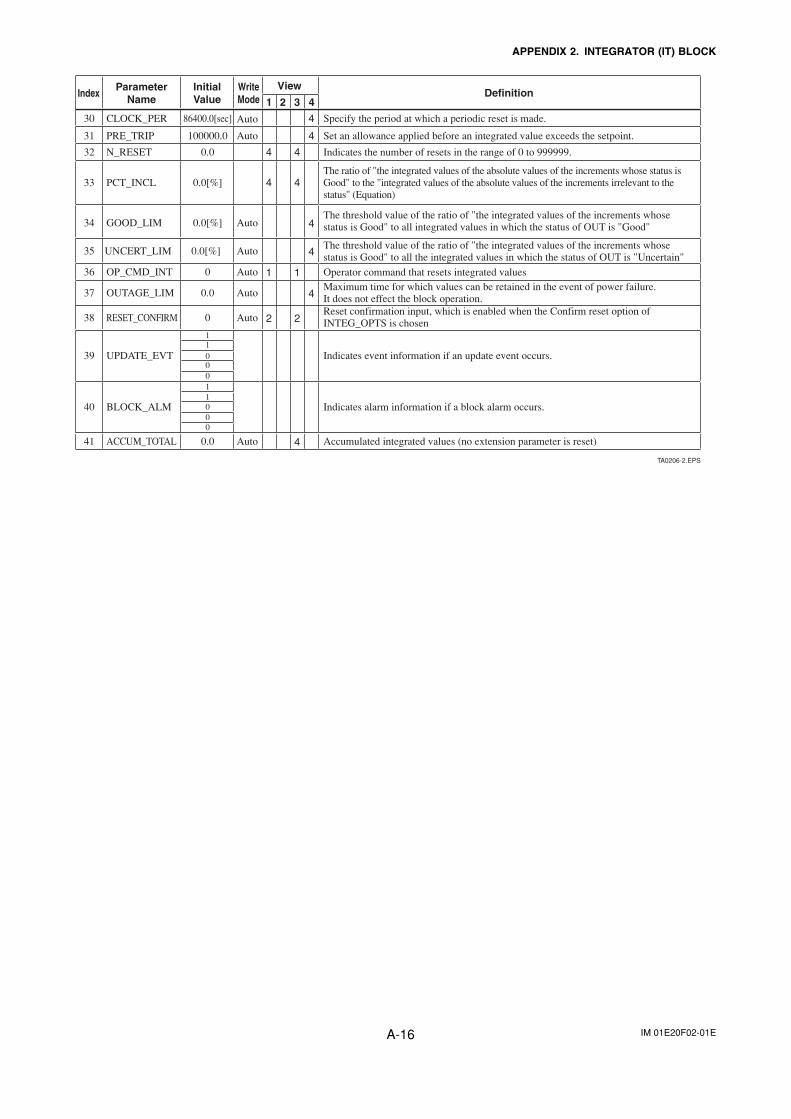
IM 01E20F02-01EA-16
APPENDIX 2. INTEGRATOR (IT) BLOCK
TA0206-2.EPS
CLOCK_PER 86400.0[sec] Specify the period at which a periodic reset is made.
PRE_TRIP 100000.0 Set an allowance applied before an integrated value exceeds the setpoint.
N_RESET 0.0 Indicates the number of resets in the range of 0 to 999999.
PCT_INCL 0.0[%]
0.0[%]
0.0[%]
The ratio of "the integrated values of the absolute values of the increments whose status is Good" to the "integrated values of the absolute values of the increments irrelevant to the status" (Equation)
GOOD_LIMThe threshold value of the ratio of "the integrated values of the increments whose status is Good" to all integrated values in which the status of OUT is "Good"
UNCERT_LIM The threshold value of the ratio of "the integrated values of the increments whose status is Good" to all the integrated values in which the status of OUT is "Uncertain"
OP_CMD_INT 0
0.0
Operator command that resets integrated values
OUTAGE_LIMMaximum time for which values can be retained in the event of power failure.It does not effect the block operation.
RESET_CONFIRM 0Reset confirmation input, which is enabled when the Confirm reset option of INTEG_OPTS is chosen
UPDATE_EVT Indicates event information if an update event occurs.
BLOCK_ALM
1
000
11
1000
Indicates alarm information if a block alarm occurs.
30
31
32
33
34
35
36
37
38
39
40
41 ACCUM_TOTAL 0.0 Accumulated integrated values (no extension parameter is reset)
4
4
4 4
4 4
4
4
1 1
4
2 2
4
Index ParameterName
InitialValue
WriteMode
Definition1 2 3 4
View
Auto
Auto
Auto
Auto
Auto
Auto
Auto
Auto

IM 01E20F02-01EA-17
APPENDIX 3. ARITHMETIC (AR) BLOCK
APPENDIX 3. ARITHMETIC (AR) BLOCK
The Arithmetic (AR) block switches two main inputsof different measurement ranges seamlessly andcombines the result with three auxiliary inputs throughthe selected compensation function (10 types) tocalculate the output.
A3.1 Schematic Diagram of Arithmetic BlockThe diagram below shows the Arithmetic block schematic.
FA0301.EPS
Figure A3.1 AR Block
The Arithmetic block is divided into three sections:
· Input section: Makes a go/no-go decision onthe use of an input value, switches the range, anddetermines the PV status.
· Computation section: Makes calculationsthrough ARITH_TYPE.
· Output section: Applies gain multiplication andbias addition to the calculated result to performlimitation processing for output.
* The range extension function compensates the IN andIN_LO input values when two devices with differentranges are connected, to make smooth input switch-ing.
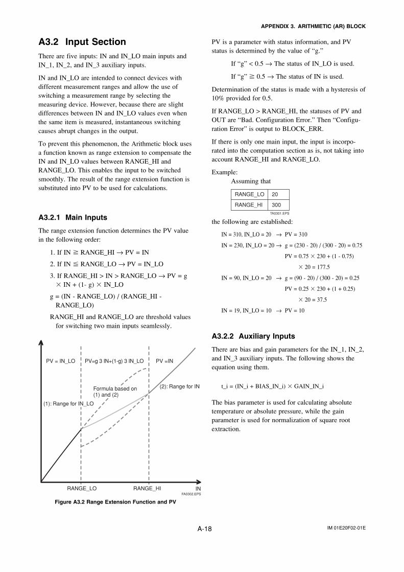
IM 01E20F02-01EA-18
APPENDIX 3. ARITHMETIC (AR) BLOCK
A3.2 Input SectionThere are five inputs: IN and IN_LO main inputs andIN_1, IN_2, and IN_3 auxiliary inputs.
IN and IN_LO are intended to connect devices withdifferent measurement ranges and allow the use ofswitching a measurement range by selecting themeasuring device. However, because there are slightdifferences between IN and IN_LO values even whenthe same item is measured, instantaneous switchingcauses abrupt changes in the output.
To prevent this phenomenon, the Arithmetic block usesa function known as range extension to compensate theIN and IN_LO values between RANGE_HI andRANGE_LO. This enables the input to be switchedsmoothly. The result of the range extension function issubstituted into PV to be used for calculations.
A3.2.1 Main Inputs
The range extension function determines the PV valuein the following order:
1. If IN � RANGE_HI → PV = IN
2. If IN � RANGE_LO → PV = IN_LO
3. If RANGE_HI > IN > RANGE_LO → PV = g� IN + (1- g) � IN_LO
g = (IN - RANGE_LO) / (RANGE_HI -RANGE_LO)
RANGE_HI and RANGE_LO are threshold valuesfor switching two main inputs seamlessly.
FA0302.EPSRANGE_LO
PV = IN_LO PV=g 3 IN+(1-g) 3 IN_LO PV =IN
RANGE_HI IN
Formula based on (1) and (2)
(2): Range for IN
(1): Range for IN_LO
Figure A3.2 Range Extension Function and PV
PV is a parameter with status information, and PVstatus is determined by the value of “g.”
If “g” < 0.5 → The status of IN_LO is used.
If “g” � 0.5 → The status of IN is used.
Determination of the status is made with a hysteresis of10% provided for 0.5.
If RANGE_LO > RANGE_HI, the statuses of PV andOUT are “Bad. Configuration Error.” Then “Configu-ration Error” is output to BLOCK_ERR.
If there is only one main input, the input is incorpo-rated into the computation section as is, not taking intoaccount RANGE_HI and RANGE_LO.
Example:Assuming that
RANGE_LO 20
RANGE_HI 300TA0301.EPS
the following are established:
IN = 310, IN_LO = 20 → PV = 310
IN = 230, IN_LO = 20 → g = (230 - 20) / (300 - 20) = 0.75
PV = 0.75 � 230 + (1 - 0.75)
� 20 = 177.5
IN = 90, IN_LO = 20 → g = (90 - 20) / (300 - 20) = 0.25
PV = 0.25 � 230 + (1 + 0.25)
� 20 = 37.5
IN = 19, IN_LO = 10 → PV = 10
A3.2.2 Auxiliary Inputs
There are bias and gain parameters for the IN_1, IN_2,and IN_3 auxiliary inputs. The following shows theequation using them.
t_i = (IN_i + BIAS_IN_i) � GAIN_IN_i
The bias parameter is used for calculating absolutetemperature or absolute pressure, while the gainparameter is used for normalization of square rootextraction.

IM 01E20F02-01EA-19
APPENDIX 3. ARITHMETIC (AR) BLOCK
A3.2.3 INPUT_OPTS
INPUT_OPTS has an option that handles an input with“uncertain” or “bad” status as a “good” status input.
Bit
0
1
2
3
4
5
6
7
8 to 15
TA0302.EPS
Function
Handles IN as a “good” status input if its status is “uncertain.”
Handles IN_LO as a “good” status input if its status is “uncertain.”
Handles IN_1 as a “good” status input if its status is “uncertain.”
Handles IN_1 as a “good” status input if its status is “bad.”
Handles IN_2 as a “good” status input if its status is “uncertain.”
Handles IN_2 as a “good” status input if its status is “bad.”
Handles IN_3 as a “good” status input if its status is “uncertain.”
Handles IN_3 as a “good” status input if its status is “bad.”
Reserved
There are options called “IN Use uncertain” and“IN_LO Use uncertain” for the IN and IN_LO inputs.When these options are valid, IN and IN_LO areinternally interpreted as “good” IN and IN_LO even iftheir statuses are “uncertain.” (There is no option for“bad” status.)
For the IN_1, IN_2, and IN_3 auxiliary inputs, thereare options known as “IN_i Use uncertain” and “IN_iUse bad.” If these options are valid, an IN_i with“uncertain” or “bad” status is internally interpreted as a“good” IN_i.
* The exception is that if the input status is “Bad. NotConnected,” INPUT_OPTS does not apply and theinput is considered “bad” as is.
A3.2.4 Relationship between the MainInputs and PV
The value and PV status are determined by the statusesof two main inputs, INPUT_OPTS, and RANGE_LOand RANGE_HI.
· If the statuses of two main inputs are both “good” oranything other than “good”See A4.2.1, Main Inputs.
· If only one of two main inputs has “good” status afterapplication of INPUT_OPTS, the PV value isdetermined as follows:
· If the status of IN is “good” and that of “IN_LO”is anything other than “good”
IN > RANGE_LO → PV = IN
IN � RANGE_LO → See A3.2.1.
· If the status of IN is anything other than “good”and that of “IN_LO” is “good”
IN_LO < RANGE_HI → PV = IN_LO
IN_LO � RANGE_H → See A3.2.1.
RANGE_LO
RANGE_HI
PV = IN_LO
PV = IN
PV = g � IN + (1-g) � IN_LO
PV = g � IN + (1-g) � IN_LO
IN
IN_LO
FA0303.EPS
If the status of IN is “good” and that of “IN_LO” is anything other than “good”
If the status of IN is anything other than “good” and that of “IN_LO” is “good”
IM 01E20F02-01EA-20
APPENDIX 3. ARITHMETIC (AR) BLOCK
A3.3 Computation Section
A3.3.1 Computing Equations
This subsection shows computing equations used in thecomputation section:
1) Flow compensation (linear)
func = PV � f
f = (t_1 / t_2)
2) Flow compensation (square root)
func = PV � f
f = sqrt(t_1 / t_2 / t_3)
3) Flow compensation (approximate expression)
func = PV � f
f = sqrt(t_1 � t_2 � t_3 � t_3)
4) Quantity of heat calculation
func = PV � f
f = (t_1 - t_2)
5) Multiplication and division
func = PV � f
f = ((t_1 / t_2) + t_3)
6) Average calculation
func = (PV + t_1 + t_2 + t_3) / N
where N: number of inputs
7) Summation
func = PV + t_1 + t_2 + t_3
8) Polynomial computation
func = PV + t_12 + t_23 + t_34
9) HTG-level compensation
func = (PV - t_1) / (PV - t_2)
10) Polynomial computation
func = PV + t_1 � PV2 + t_2 � PV3 + t_3 � PV4
* Precaution for computation
Division by “0”: If a value is divided by “0,” thecalculation result is interpretedas 1037 and, depending withcore, a plus sign is added to it.
Negative square root: The square root of an absolutevalue is extracted and a minussign is added to it.
A3.3.2 Compensated Values
In computing equations 1) to 5) in A3.3.1, the value“f” is restricted by the COMP_HI_LIM orCOMP_LO_LIM parameter. In this case, the value “f”is treated as follows:
If “f” > COMP_HI_LIM,
f = COMP_HI_LIM
If “f” < COMP_LO_LIM,
f = COMP_LO_LIM
A3.3.3 Average Calculation
In computing equation 6) in A3.3.1, the average ofinput value is calculated. Here, it is necessary to obtainthe number of inputs, N. For this, determination ismade to see if the sub-status of each input is “NotConnected.” Note that the main inputs may be acceptedif IN or IN_LO is not in “Not Connected” sub-status.In this case, the number of inputs that are not in “NotConnected” sub-status is regarded as “N.”
A3.4 Output SectionAfter executing the computing equation, the blockapplies a gain to the calculated result and then adds abias to it.
It then substitutes the result into PRE_OUT and if themode is in AUTO, the value of PRE_OUT is taken asOUT.
PRE_OUT = func � gain + bias
where func: result of computing equation execution
OUT = PRE_OUT (when the mode is in AUTO)
Next, the block performs limitation processing(OUT_HI_LIM, OUT_LOW_LIM). This processing isdescribed as follows with respect to the value ofPRE_OUT.
If PRE_OUT > OUT_HI_LIM:
PRE_OUT = OUT_HI_LIM
The “high limited” processing is appliedto the status of PRE_OUT.
If PRE_OUT < OUT_LO_LIM:
PRE_OUT = OUT_LO_LIM
The “low limited” processing is appliedto the status of PRE_OUT.
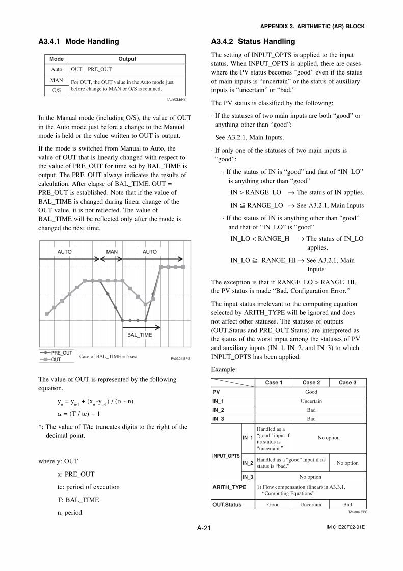
IM 01E20F02-01EA-21
APPENDIX 3. ARITHMETIC (AR) BLOCK
A3.4.1 Mode Handling
TA0303.EPS
Auto
MAN
O/S
Mode Output
OUT = PRE_OUT
For OUT, the OUT value in the Auto mode just before change to MAN or O/S is retained.
In the Manual mode (including O/S), the value of OUTin the Auto mode just before a change to the Manualmode is held or the value written to OUT is output.
If the mode is switched from Manual to Auto, thevalue of OUT that is linearly changed with respect tothe value of PRE_OUT for time set by BAL_TIME isoutput. The PRE_OUT always indicates the results ofcalculation. After elapse of BAL_TIME, OUT =PRE_OUT is established. Note that if the value ofBAL_TIME is changed during linear change of theOUT value, it is not reflected. The value ofBAL_TIME will be reflected only after the mode ischanged the next time.
FA0304.EPS
PRE_OUTPRE_OUTOUTOUT
AUTOAUTO MANMAN AUTOAUTO
BAL_TIMEBAL_TIME
Case of BAL_TIME = 5 sec
The value of OUT is represented by the followingequation.
yn = y
n-1 + (x
n -y
n-1) / (� - n)
� = (T / tc) + 1
*: The value of T/tc truncates digits to the right of thedecimal point.
where y: OUT
x: PRE_OUT
tc: period of execution
T: BAL_TIME
n: period
A3.4.2 Status Handling
The setting of INPUT_OPTS is applied to the inputstatus. When INPUT_OPTS is applied, there are caseswhere the PV status becomes “good” even if the statusof main inputs is “uncertain” or the status of auxiliaryinputs is “uncertain” or “bad.”
The PV status is classified by the following:
· If the statuses of two main inputs are both “good” oranything other than “good”:
See A3.2.1, Main Inputs.
· If only one of the statuses of two main inputs is“good”:
· If the status of IN is “good” and that of “IN_LO”is anything other than “good”
IN > RANGE_LO → The status of IN applies.
IN � RANGE_LO → See A3.2.1, Main Inputs
· If the status of IN is anything other than “good”and that of “IN_LO” is “good”
IN_LO < RANGE_H → The status of IN_LOapplies.
IN_LO � RANGE_HI → See A3.2.1, MainInputs
The exception is that if RANGE_LO > RANGE_HI,the PV status is made “Bad. Configuration Error.”
The input status irrelevant to the computing equationselected by ARITH_TYPE will be ignored and doesnot affect other statuses. The statuses of outputs(OUT.Status and PRE_OUT.Status) are interpreted asthe status of the worst input among the statuses of PVand auxiliary inputs (IN_1, IN_2, and IN_3) to whichINPUT_OPTS has been applied.
Example:
GoodPV
UncertainIN_1
BadIN_2
BadIN_3
ARITH_TYPE
Good Uncertain BadOUT.Status
INPUT_OPTS
IN_1
IN_2
IN_3
TA0304.EPS
Case 1 Case 2 Case 3
Handled as a“good” input ifits status is “uncertain.”
No option
No option
No option
Handled as a “good” input if itsstatus is “bad.”
1) Flow compensation (linear) in A3.3.1, “Computing Equations”
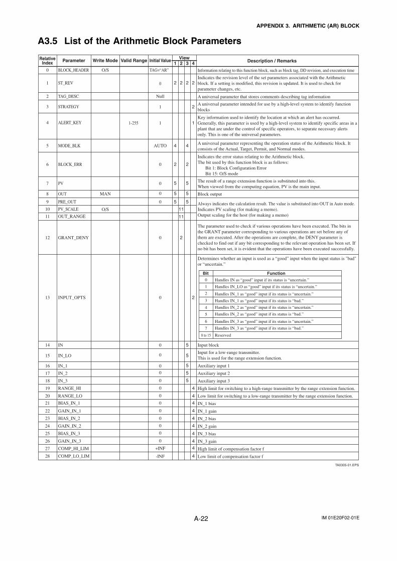
IM 01E20F02-01EA-22
APPENDIX 3. ARITHMETIC (AR) BLOCK
A3.5 List of the Arithmetic Block Parameters
TA0305-01.EPS
RelativeIndex Parameter Write Mode Valid Range Initial Value View
21 3
5 5
5
5
5
5
5
4
4O/S
MAN
O/S
2
11
2 2 2
BLOCK_HEADER
TAG_DESC
4 4MODE_BLK
OUT
OUT_RANGE
IN_LO
IN_1
IN_2
IN_3
ST_REV
IN
TAG=“AR”
2STRATEGY
5 5PV
2 2BLOCK_ERR
5 5PRE_OUT
2GRANT_DENY
11PV_SCALE
RANGE_HI
4
4
4
RANGE_LO
BIAS_IN_1
GAIN_IN_1
4
4
4
4
4
BIAS_IN_2
GAIN_IN_2
BIAS_IN_3
GAIN_IN_3
COMP_HI_LIM
4COMP_LO_LIM
ALERT_KEY 1-255 1
0
2
8
15
16
17
18
14
5
11
1
3
7
6
9
12
10
19
20
21
22
23
24
25
26
27
28
4
0
Null
1
0
0
0
0
0
0
0
0
0
0
0
0
0
0
0
0
0
0
+INF
-INF
1
AUTO
13 INPUT_OPTS 0 2
Description / Remarks
Information relating to this function block, such as block tag, DD revision, and execution time
A universal parameter that stores comments describing tag information
Block output
Always indicates the calculation result. The value is substituted into OUT in Auto mode.Indicates PV scaling (for making a memo).Output scaling for the host (for making a memo)
Function Bit
0
1
2
3
4
5
6
7
8 to 15
Handles IN as “good” input if its status is “uncertain.”
Handles IN_LO as “good” input if its status is “uncertain.”
Handles IN_1 as “good” input if its status is “uncertain.”
Handles IN_1 as “good” input if its status is “bad.”
Handles IN_2 as “good” input if its status is “uncertain.”
Handles IN_2 as “good” input if its status is “bad.”
Handles IN_3 as “good” input if its status is “uncertain.”
Handles IN_3 as “good” input if its status is “bad.”
Reserved
Input block
Auxiliary input 1
Auxiliary input 2
Auxiliary input 3
High limit for switching to a high-range transmitter by the range extension function.
Low limit for switching to a low-range transmitter by the range extension function.
IN_1 bias
IN_1 gain
IN_2 bias
IN_2 gain
IN_3 bias
IN_3 gain
High limit of compensation factor f
Low limit of compensation factor f
A universal parameter intended for use by a high-level system to identify function blocks
A universal parameter representing the operation status of the Arithmetic block. It consists of the Actual, Target, Permit, and Normal modes.
The result of a range extension function is substituted into this. When viewed from the computing equation, PV is the main input.
Input for a low-range transmitter. This is used for the range extension function.
Determines whether an input is used as a “good” input when the input status is "bad" or “uncertain.”
Indicates the error status relating to the Arithmetic block. The bit used by this function block is as follows: Bit 1: Block Configuration Error Bit 15: O/S mode
The parameter used to check if various operations have been executed. The bits in the GRANT parameter corresponding to various operations are set before any of them are executed. After the operations are complete, the DENY parameter is checked to find out if any bit corresponding to the relevant operation has been set. If no bit has been set, it is evident that the operations have been executed successfully.
Indicates the revision level of the set parameters associated with the Arithmetic block. If a setting is modified, this revision is updated. It is used to check for parameter changes, etc.
Key information used to identify the location at which an alert has occurred. Generally, this parameter is used by a high-level system to identify specific areas in a plant that are under the control of specific operators, to separate necessary alerts only. This is one of the universal parameters.
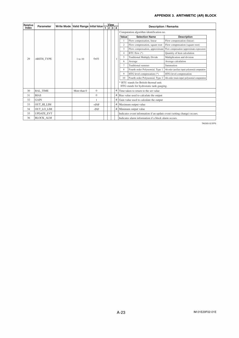
IM 01E20F02-01EA-23
APPENDIX 3. ARITHMETIC (AR) BLOCK
TA0305-02.EPS
4
4
4
BAL_TIME
BIAS
GAIN
4OUT_HI_LIM
4OUT_LO_LIM
UPDATE_EVT
BLOCK_ALM
More than 030
31
32
33
34
35
36
0
0
1
+INF
-INF
1 to 10 129 ARITH_TYPE 0x01
RelativeIndex Parameter Write Mode Valid Range Initial Value View
21 3 4 Description / Remarks
Computation algorithm identification no.
Value Selection Name Description1
2
3
4
5
6
7
8
9
10
Flow compensation, linear
Flow compensation, square root
Flow compensation, approximate
BTU flow (*)
Traditional Multiply Divide
Average
Traditional summer
Fourth order Polynomial, Type 1
HTG level compensation (*)
Fourth order Polynomial, Type 2
Flow compensation (linear)
Flow compensation (square root)
Flow compensation (approximate expression)
Quantity of heat calculation
Multiplication and division
Average calculation
Summation
4th-order (auxiliary input) polynomial computation
HTG-level compensation
4th-order (main input) polynomial computation
* BTU stands for British thermal unit. HTG stands for hydrostatic tank gauging.
Time taken to return to the set value
Bias value used to calculate the output
Gain value used to calculate the output
Maximum output value
Minimum output value
Indicates alarm information if a block alarm occurs.
Indicates event information if an update event (setting change) occurs.
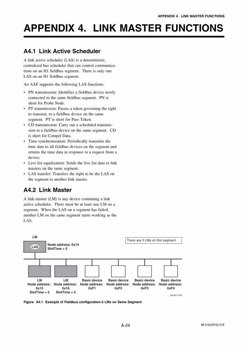
IM 01E20F02-01EA-24
APPENDIX 4. LINK MASTER FUNCTIONS
APPENDIX 4. LINK MASTER FUNCTIONS
A4.1 Link Active SchedulerA link active scheduler (LAS) is a deterministic,centralized bus scheduler that can control communica-tions on an H1 fieldbus segment. There is only oneLAS on an H1 fieldbus segment.
An AXF supports the following LAS functions.
• PN transmission: Identifies a fieldbus device newlyconnected to the same fieldbus segment. PN isshort for Probe Node.
• PT transmission: Passes a token governing the rightto transmit, to a fieldbus device on the samesegment. PT is short for Pass Token.
• CD transmission: Carry out a scheduled transmis-sion to a fieldbus device on the same segment. CDis short for Compel Data.
• Time synchronization: Periodically transmits thetime data to all fieldbus devices on the segment andreturns the time data in response to a request from adevice.
• Live list equalization: Sends the live list data to linkmasters on the same segment.
• LAS transfer: Transfers the right to be the LAS onthe segment to another link master.
A4.2 Link MasterA link master (LM) is any device containing a linkactive scheduler. There must be at least one LM on asegment. When the LAS on a segment has failed,another LM on the same segment starts working as theLAS.
LMNode address:
0x15SlotTime = 5
LMNode address:
0x16SlotTime = 5
Node address: 0x14SlotTime = 5
Basic deviceNode address:
0xF1
Basic deviceNode address:
0xF2
Basic deviceNode address:
0xF3
Basic deviceNode address:
0xF4
LAS
There are 3 LMs on this segment. LM
FA0401.EPS
Figure A4.1 Example of Fieldbus configuration-3 LMs on Same Segment
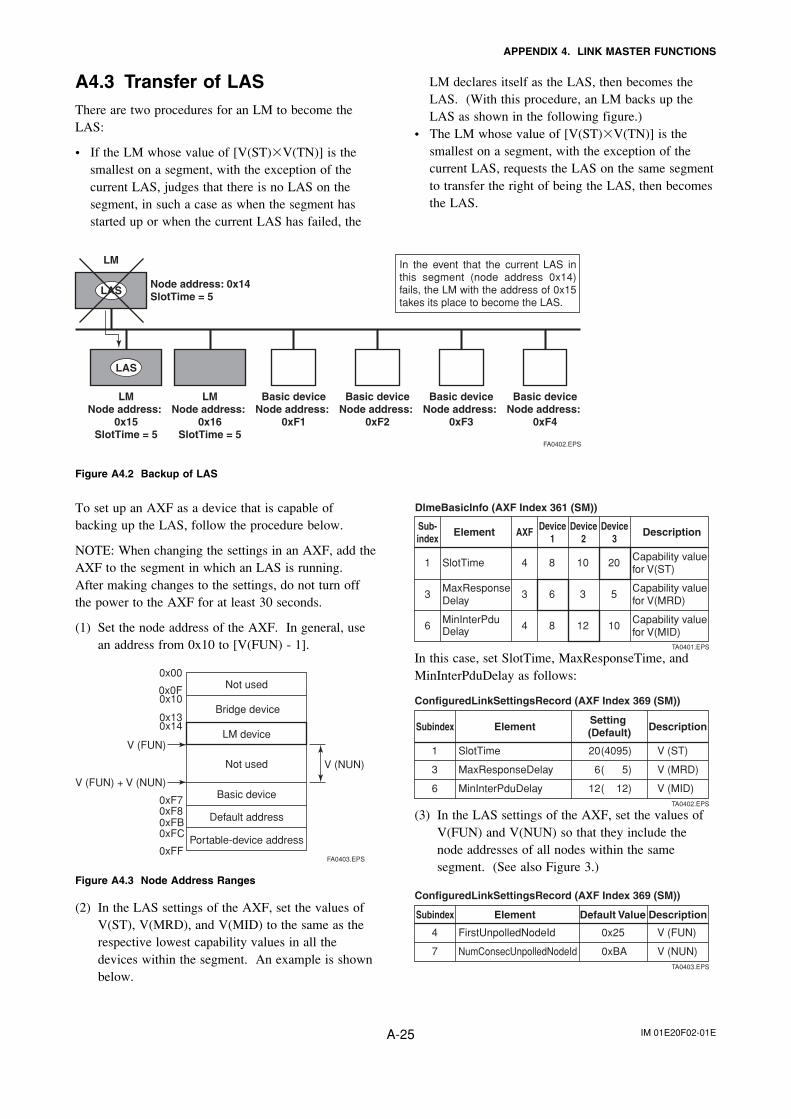
IM 01E20F02-01EA-25
APPENDIX 4. LINK MASTER FUNCTIONS
A4.3 Transfer of LASThere are two procedures for an LM to become theLAS:
• If the LM whose value of [V(ST)�V(TN)] is thesmallest on a segment, with the exception of thecurrent LAS, judges that there is no LAS on thesegment, in such a case as when the segment hasstarted up or when the current LAS has failed, the
To set up an AXF as a device that is capable ofbacking up the LAS, follow the procedure below.
NOTE: When changing the settings in an AXF, add theAXF to the segment in which an LAS is running.After making changes to the settings, do not turn offthe power to the AXF for at least 30 seconds.
(1) Set the node address of the AXF. In general, usean address from 0x10 to [V(FUN) - 1].
Not used
LM device
Not used
Basic device
Default address
Portable-device address
V (FUN)
V (FUN) + V (NUN)
V (NUN)
0xFF
0xFC0xFB0xF80xF7
0x00
FA0403.EPS
0x0F0x10
0x130x14
Bridge device
Figure A4.3 Node Address Ranges
(2) In the LAS settings of the AXF, set the values ofV(ST), V(MRD), and V(MID) to the same as therespective lowest capability values in all thedevices within the segment. An example is shownbelow.
Sub-index
Element AXF Device1
Device2
Device3
Description
1
3
6
SlotTime MaxResponse Delay
MinInterPdu Delay
4
3
4
8
6
8
10
3
12
20
5
10
Capability value for V(ST)
Capability value for V(MRD)
Capability value for V(MID)
TA0401.EPS
DlmeBasicInfo (AXF Index 361 (SM))
In this case, set SlotTime, MaxResponseTime, andMinInterPduDelay as follows:
Subindex Element
ConfiguredLinkSettingsRecord (AXF Index 369 (SM))
DescriptionSetting (Default)
V (ST)
V (MRD)
V (MID)
20
6
12
(4095)
( 5)
( 12)
SlotTime
MaxResponseDelay
MinInterPduDelay
1
3
6TA0402.EPS
(3) In the LAS settings of the AXF, set the values ofV(FUN) and V(NUN) so that they include thenode addresses of all nodes within the samesegment. (See also Figure 3.)
Subindex Element
ConfiguredLinkSettingsRecord (AXF Index 369 (SM))
DescriptionDefault Value
V (FUN)
V (NUN)
0x25
0xBA
FirstUnpolledNodeId
NumConsecUnpolledNodeId
4
7TA0403.EPS
LM declares itself as the LAS, then becomes theLAS. (With this procedure, an LM backs up theLAS as shown in the following figure.)
• The LM whose value of [V(ST)�V(TN)] is thesmallest on a segment, with the exception of thecurrent LAS, requests the LAS on the same segmentto transfer the right of being the LAS, then becomesthe LAS.
LMNode address:
0x15SlotTime = 5
LMNode address:
0x16SlotTime = 5
Node address: 0x14SlotTime = 5
Basic deviceNode address:
0xF1
Basic deviceNode address:
0xF2
Basic deviceNode address:
0xF3
Basic deviceNode address:
0xF4
LAS
LAS
In the event that the current LAS in this segment (node address 0x14) fails, the LM with the address of 0x15 takes its place to become the LAS.
LM
FA0402.EPS
Figure A4.2 Backup of LAS
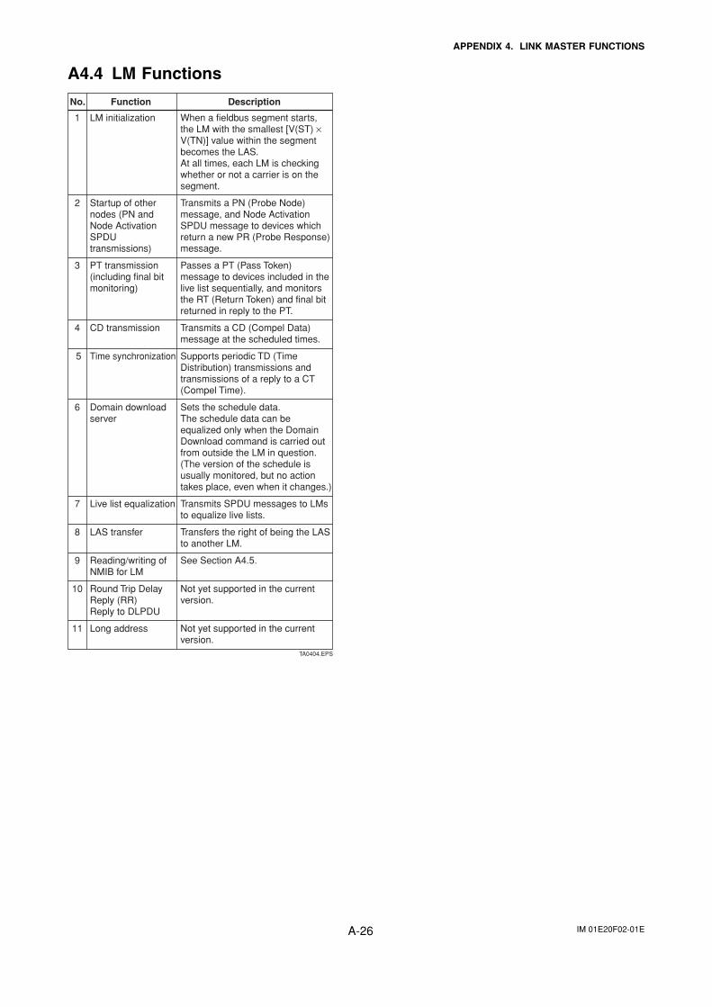
IM 01E20F02-01EA-26
APPENDIX 4. LINK MASTER FUNCTIONS
A4.4 LM Functions
No. Function Description
LM initialization
Startup of other nodes (PN and Node Activation SPDU transmissions)
PT transmission (including final bit monitoring)
CD transmission
Time synchronization
Domain download server
Live list equalization
LAS transfer
Reading/writing of NMIB for LM
Round Trip Delay Reply (RR)Reply to DLPDU
Long address
1
2
3
4
5
6
7
8
9
10
11
TA0404.EPS
When a fieldbus segment starts, the LM with the smallest [V(ST) × V(TN)] value within the segment becomes the LAS. At all times, each LM is checking whether or not a carrier is on the segment.
Transmits a PN (Probe Node) message, and Node Activation SPDU message to devices which return a new PR (Probe Response) message.
Passes a PT (Pass Token) message to devices included in the live list sequentially, and monitors the RT (Return Token) and final bit returned in reply to the PT.
Transmits a CD (Compel Data) message at the scheduled times.
Supports periodic TD (Time Distribution) transmissions and transmissions of a reply to a CT (Compel Time).
Sets the schedule data. The schedule data can be equalized only when the Domain Download command is carried out from outside the LM in question. (The version of the schedule is usually monitored, but no action takes place, even when it changes.)
Transmits SPDU messages to LMs to equalize live lists.
Transfers the right of being the LAS to another LM.
See Section A4.5.
Not yet supported in the current version.
Not yet supported in the current version.
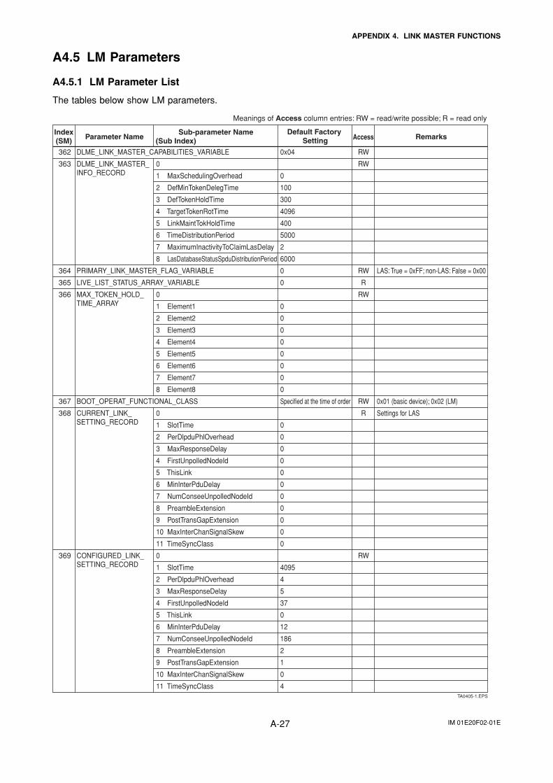
IM 01E20F02-01EA-27
APPENDIX 4. LINK MASTER FUNCTIONS
A4.5 LM Parameters
A4.5.1 LM Parameter List
The tables below show LM parameters.
362
363
364
365
366
367
368
369
0
1 MaxSchedulingOverhead
2 DefMinTokenDelegTime
3 DefTokenHoldTime
4 TargetTokenRotTime
5 LinkMaintTokHoldTime
6 TimeDistributionPeriod
7 MaximumInactivityToClaimLasDelay
8 LasDatabaseStatusSpduDistributionPeriod
0
1 Element1
2 Element2
3 Element3
4 Element4
5 Element5
6 Element6
7 Element7
8 Element8
0
1 SlotTime
2 PerDlpduPhlOverhead
3 MaxResponseDelay
4 FirstUnpolledNodeId
5 ThisLink
6 MinInterPduDelay
7 NumConseeUnpolledNodeId
8 PreambleExtension
9 PostTransGapExtension
10 MaxInterChanSignalSkew
11 TimeSyncClass
0
1 SlotTime
2 PerDlpduPhlOverhead
3 MaxResponseDelay
4 FirstUnpolledNodeId
5 ThisLink
6 MinInterPduDelay
7 NumConseeUnpolledNodeId
8 PreambleExtension
9 PostTransGapExtension
10 MaxInterChanSignalSkew
11 TimeSyncClass
0x04
0
100
300
4096
400
5000
2
6000
0
0
0
0
0
0
0
0
0
0
Specified at the time of order
0
0
0
0
0
0
0
0
0
0
0
4095
4
5
37
0
12
186
2
1
0
4
LAS: True = 0xFF; non-LAS: False = 0x00
0x01 (basic device); 0x02 (LM)
Settings for LAS
RW
RW
RW
R
RW
RW
R
RW
TA0405-1.EPS
Meanings of Access column entries: RW = read/write possible; R = read only
DLME_LINK_MASTER_CAPABILITIES_VARIABLE
DLME_LINK_MASTER_INFO_RECORD
PRIMARY_LINK_MASTER_FLAG_VARIABLE
LIVE_LIST_STATUS_ARRAY_VARIABLE
MAX_TOKEN_HOLD_TIME_ARRAY
BOOT_OPERAT_FUNCTIONAL_CLASS
CURRENT_LINK_SETTING_RECORD
CONFIGURED_LINK_SETTING_RECORD
Index(SM)
Sub-parameter NameAccess(Sub Index)Parameter Name
Default Factory Setting Remarks
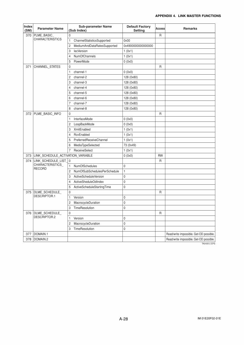
IM 01E20F02-01EA-28
APPENDIX 4. LINK MASTER FUNCTIONS
370
371
372
373
374
375
376
377
378
0
1 ChannelStatisticsSupported
2 MediumAndDataRatesSupported
3 IecVersion
4 NumOfChannels
5 PowerMode
0
1 channel-1
2 channel-2
3 channel-3
4 channel-4
5 channel-5
6 channel-6
7 channel-7
8 channel-8
0
1 InterfaceMode
2 LoopBackMode
3 XmitEnabled
4 RcvEnabled
5 PreferredReceiveChannel
6 MediaTypeSelected
7 ReceiveSelect
0
1 NumOfSchedules
2 NumOfSubSchedulesPerSchedule
3 ActiveScheduleVersion
4 ActiveSheduleOdIndex
5 ActiveScheduleStartingTime
0
1 Version
2 MacrocycleDuration
3 TimeResolution
0
1 Version
2 MacrocycleDuration
3 TimeResolution
0x00
0x4900000000000000
1 (0x1)
1 (0x1)
0 (0x0)
0 (0x0)
128 (0x80)
128 (0x80)
128 (0x80)
128 (0x80)
128 (0x80)
128 (0x80)
128 (0x80)
0 (0x0)
0 (0x0)
1 (0x1)
1 (0x1)
1 (0x1)
73 (0x49)
1 (0x1)
0 (0x0)
0
1
0
0
0
0
0
0
0
0
0
Read/write impossible. Get-OD possible.
Read/write impossible. Get-OD possible.
R
R
R
RW
R
R
R
TA0405-2.EPS
Index(SM)
Sub-parameter NameAccess(Sub Index)Parameter Name
Default Factory Setting Remarks
PLME_BASIC_CHARACTERISTICS
CHANNEL_STATES
PLME_BASIC_INFO
LINK_SCHEDULE_ACTIVATION_VARIABLE
LINK_SCHEDULE_LIST_CHARACTERISTICS_RECORD
DLME_SCHEDULE_DESCRIPTOR.1
DLME_SCHEDULE_DESCRIPTOR.2
DOMAIN.1
DOMAIN.2
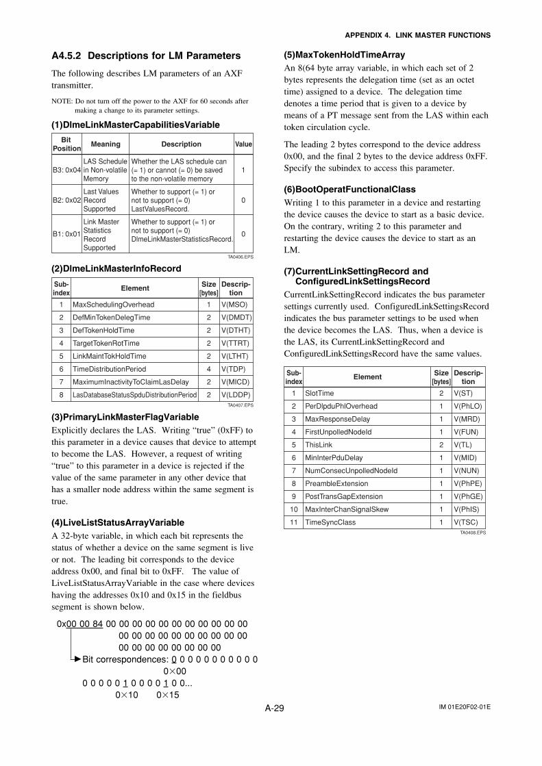
IM 01E20F02-01EA-29
APPENDIX 4. LINK MASTER FUNCTIONS
A4.5.2 Descriptions for LM Parameters
The following describes LM parameters of an AXFtransmitter.
NOTE: Do not turn off the power to the AXF for 60 seconds aftermaking a change to its parameter settings.
(1)DlmeLinkMasterCapabilitiesVariable
MeaningBit Position
ValueDescription
1
0
0
LAS Schedule in Non-volatile Memory
Last Values Record Supported
Link Master Statistics Record Supported
Whether the LAS schedule can (= 1) or cannot (= 0) be saved to the non-volatile memory
Whether to support (= 1) or not to support (= 0) LastValuesRecord.
Whether to support (= 1) or not to support (= 0) DlmeLinkMasterStatisticsRecord.
B3: 0x04
B2: 0x02
B1: 0x01
TA0406.EPS
(2)DlmeLinkMasterInfoRecord
ElementSub-index
Descrip-tion
Size[bytes]
1
2
2
2
2
4
2
2
V(MSO)
V(DMDT)
V(DTHT)
V(TTRT)
V(LTHT)
V(TDP)
V(MICD)
V(LDDP)
MaxSchedulingOverhead
DefMinTokenDelegTime
DefTokenHoldTime
TargetTokenRotTime
LinkMaintTokHoldTime
TimeDistributionPeriod
MaximumInactivityToClaimLasDelay
LasDatabaseStatusSpduDistributionPeriod
1
2
3
4
5
6
7
8TA0407.EPS
(3)PrimaryLinkMasterFlagVariableExplicitly declares the LAS. Writing “true” (0xFF) tothis parameter in a device causes that device to attemptto become the LAS. However, a request of writing“true” to this parameter in a device is rejected if thevalue of the same parameter in any other device thathas a smaller node address within the same segment istrue.
(4)LiveListStatusArrayVariableA 32-byte variable, in which each bit represents thestatus of whether a device on the same segment is liveor not. The leading bit corresponds to the deviceaddress 0x00, and final bit to 0xFF. The value ofLiveListStatusArrayVariable in the case where deviceshaving the addresses 0x10 and 0x15 in the fieldbussegment is shown below.
0x00 00 84 00 00 00 00 00 00 00 00 00 00 0000 00 00 00 00 00 00 00 00 0000 00 00 00 00 00 00 00
Bit correspondences: 0 0 0 0 0 0 0 0 0 0 0 0�00
0 0 0 0 0 1 0 0 0 0 1 0 0... 0�10 0�15
(5)MaxTokenHoldTimeArrayAn 8(64 byte array variable, in which each set of 2bytes represents the delegation time (set as an octettime) assigned to a device. The delegation timedenotes a time period that is given to a device bymeans of a PT message sent from the LAS within eachtoken circulation cycle.
The leading 2 bytes correspond to the device address0x00, and the final 2 bytes to the device address 0xFF.Specify the subindex to access this parameter.
(6)BootOperatFunctionalClassWriting 1 to this parameter in a device and restartingthe device causes the device to start as a basic device.On the contrary, writing 2 to this parameter andrestarting the device causes the device to start as anLM.
(7)CurrentLinkSettingRecord andConfiguredLinkSettingsRecord
CurrentLinkSettingRecord indicates the bus parametersettings currently used. ConfiguredLinkSettingsRecordindicates the bus parameter settings to be used whenthe device becomes the LAS. Thus, when a device isthe LAS, its CurrentLinkSettingRecord andConfiguredLinkSettingsRecord have the same values.
ElementSub-index
Descrip-tion
Size[bytes]
2
1
1
1
2
1
1
1
1
1
1
V(ST)
V(PhLO)
V(MRD)
V(FUN)
V(TL)
V(MID)
V(NUN)
V(PhPE)
V(PhGE)
V(PhIS)
V(TSC)
SlotTime
PerDlpduPhlOverhead
MaxResponseDelay
FirstUnpolledNodeId
ThisLink
MinInterPduDelay
NumConsecUnpolledNodeId
PreambleExtension
PostTransGapExtension
MaxInterChanSignalSkew
TimeSyncClass
1
2
3
4
5
6
7
8
9
10
11TA0408.EPS
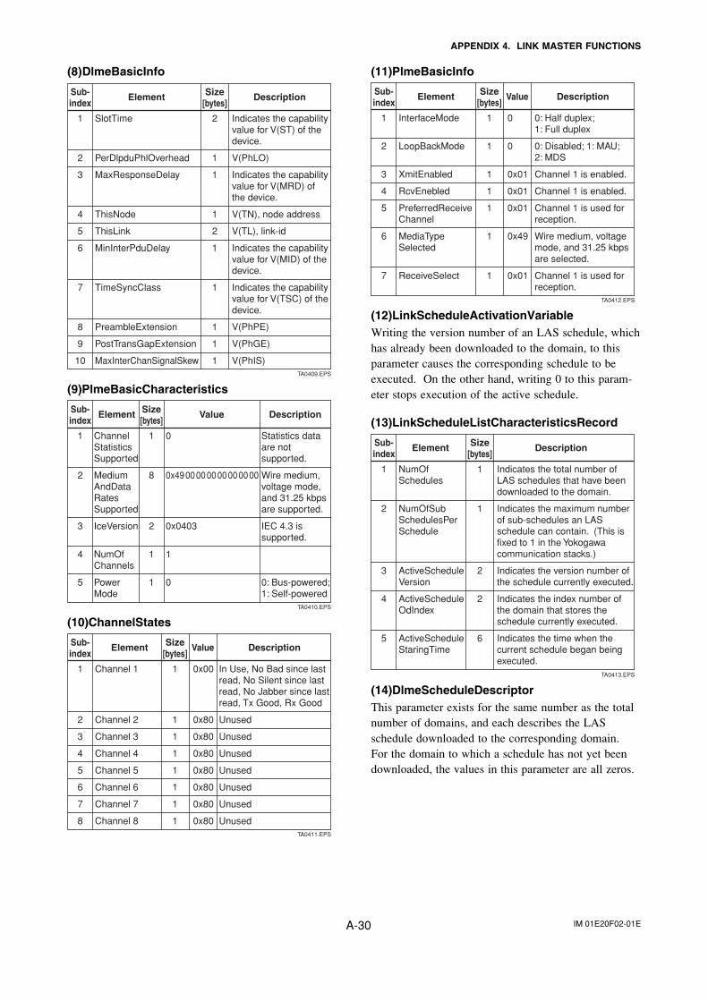
IM 01E20F02-01EA-30
APPENDIX 4. LINK MASTER FUNCTIONS
(8)DlmeBasicInfo
Element DescriptionSub-index
Size[bytes]
2
1
1
1
2
1
1
1
1
1
Indicates the capability value for V(ST) of the device.
V(PhLO)
Indicates the capability value for V(MRD) of the device.
V(TN), node address
V(TL), link-id
Indicates the capability value for V(MID) of the device.
Indicates the capability value for V(TSC) of the device.
V(PhPE)
V(PhGE)
V(PhIS)
SlotTime
PerDlpduPhlOverhead
MaxResponseDelay
ThisNode
ThisLink
MinInterPduDelay
TimeSyncClass
PreambleExtension
PostTransGapExtension
MaxInterChanSignalSkew
1
2
3
4
5
6
7
8
9
10TA0409.EPS
(9)PlmeBasicCharacteristics
Element Value DescriptionSub-index
Size[bytes]
1
8
2
1
1
Statistics data are not supported.
Wire medium, voltage mode, and 31.25 kbps are supported.
IEC 4.3 is supported.
0: Bus-powered; 1: Self-powered
ChannelStatisticsSupported
MediumAndDataRatesSupported
IceVersion
NumOfChannels
PowerMode
0
0x49 00 00 00 00 00 00 00
0x0403
1
0
1
2
3
4
5
TA0410.EPS
(10)ChannelStates
Element Value DescriptionSub-index
Size[bytes]
1
1
1
1
1
1
1
1
In Use, No Bad since last read, No Silent since last read, No Jabber since last read, Tx Good, Rx Good
Unused
Unused
Unused
Unused
Unused
Unused
Unused
Channel 1
Channel 2
Channel 3
Channel 4
Channel 5
Channel 6
Channel 7
Channel 8
0x00
0x80
0x80
0x80
0x80
0x80
0x80
0x80
1
2
3
4
5
6
7
8TA0411.EPS
(11)PlmeBasicInfo
Element Value DescriptionSub-index
Size[bytes]
1
1
1
1
1
1
1
0: Half duplex; 1: Full duplex
0: Disabled; 1: MAU; 2: MDS
Channel 1 is enabled.
Channel 1 is enabled.
Channel 1 is used for reception.
Wire medium, voltage mode, and 31.25 kbps are selected.
Channel 1 is used for reception.
InterfaceMode
LoopBackMode
XmitEnabled
RcvEnebled
PreferredReceiveChannel
MediaTypeSelected
ReceiveSelect
0
0
0x01
0x01
0x01
0x49
0x01
1
2
3
4
5
6
7
TA0412.EPS
(12)LinkScheduleActivationVariableWriting the version number of an LAS schedule, whichhas already been downloaded to the domain, to thisparameter causes the corresponding schedule to beexecuted. On the other hand, writing 0 to this param-eter stops execution of the active schedule.
(13)LinkScheduleListCharacteristicsRecord
Element DescriptionSub-index
Size[bytes]
1
1
2
2
6
Indicates the total number of LAS schedules that have been downloaded to the domain.
Indicates the maximum number of sub-schedules an LAS schedule can contain. (This is fixed to 1 in the Yokogawa communication stacks.)
Indicates the version number of the schedule currently executed.
Indicates the index number of the domain that stores the schedule currently executed.
Indicates the time when the current schedule began being executed.
NumOfSchedules
NumOfSub SchedulesPerSchedule
ActiveScheduleVersion
ActiveScheduleOdIndex
ActiveScheduleStaringTime
1
2
3
4
5
TA0413.EPS
(14)DlmeScheduleDescriptorThis parameter exists for the same number as the totalnumber of domains, and each describes the LASschedule downloaded to the corresponding domain.For the domain to which a schedule has not yet beendownloaded, the values in this parameter are all zeros.
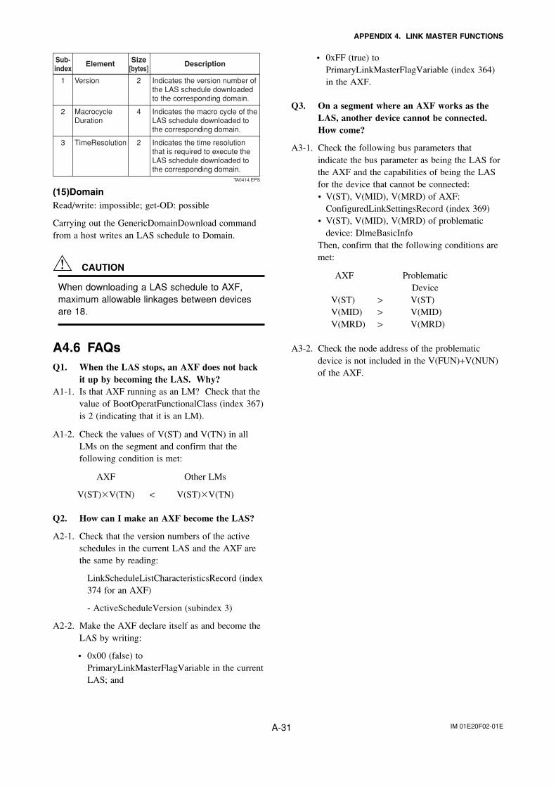
IM 01E20F02-01EA-31
APPENDIX 4. LINK MASTER FUNCTIONS
Element DescriptionSub-index
Size[bytes]
2
4
2
Indicates the version number of the LAS schedule downloaded to the corresponding domain.
Indicates the macro cycle of the LAS schedule downloaded to the corresponding domain.
Indicates the time resolution that is required to execute the LAS schedule downloaded to the corresponding domain.
Version
MacrocycleDuration
TimeResolution
1
2
3
TA0414.EPS
(15)DomainRead/write: impossible; get-OD: possible
Carrying out the GenericDomainDownload commandfrom a host writes an LAS schedule to Domain.
CAUTION
When downloading a LAS schedule to AXF,maximum allowable linkages between devicesare 18.
A4.6 FAQsQ1. When the LAS stops, an AXF does not back
it up by becoming the LAS. Why?A1-1. Is that AXF running as an LM? Check that the
value of BootOperatFunctionalClass (index 367)is 2 (indicating that it is an LM).
A1-2. Check the values of V(ST) and V(TN) in allLMs on the segment and confirm that thefollowing condition is met:
AXF Other LMs
V(ST)�V(TN) < V(ST)�V(TN)
Q2. How can I make an AXF become the LAS?
A2-1. Check that the version numbers of the activeschedules in the current LAS and the AXF arethe same by reading:
LinkScheduleListCharacteristicsRecord (index374 for an AXF)
- ActiveScheduleVersion (subindex 3)
A2-2. Make the AXF declare itself as and become theLAS by writing:
• 0x00 (false) toPrimaryLinkMasterFlagVariable in the currentLAS; and
• 0xFF (true) toPrimaryLinkMasterFlagVariable (index 364)in the AXF.
Q3. On a segment where an AXF works as theLAS, another device cannot be connected.How come?
A3-1. Check the following bus parameters thatindicate the bus parameter as being the LAS forthe AXF and the capabilities of being the LASfor the device that cannot be connected:• V(ST), V(MID), V(MRD) of AXF:
ConfiguredLinkSettingsRecord (index 369)• V(ST), V(MID), V(MRD) of problematic
device: DlmeBasicInfoThen, confirm that the following conditions aremet:
AXF ProblematicDevice
V(ST) > V(ST)V(MID) > V(MID)V(MRD) > V(MRD)
A3-2. Check the node address of the problematicdevice is not included in the V(FUN)+V(NUN)of the AXF.

IM 01E20F02-01EA-32
APPENDIX 5. PID Block
APPENDIX 5. PID BLOCK
A PID block performs the PID control computation based on the deviation of the measured value (PV) from thesetpoint (SV), and is generally used for constant-setpoint and cascaded-setpoint control.
A5.1 Function DiagramThe figure below depicts the function diagram of a PID block.
Setpoint OutputBypass
Input Filter
PID Control Computation
Alarm Processing
Mode Control
Feed-forward
Data Status Management
Output Tracking
CAS_IN
BKCAL_OUTRCAS_OUT
BKCAL_INROUT_IN ROUT_OUTFF_VAL
RCAS_IN
TRK_IN_DTRK_VAL
IN
OUT
PV
SP
FA0101.EPS
Figure A5.1 PID Block
A5.2 Functions of PID BlockThe table below shows the functions provided in a PID block.
PID control computation
Control output
Switching of direction of control action
Control action bypass
Feed-forward
Measured-value tracking
Setpoint limiters
External-output tracking
Mode change
Bumpless transfer
Initialization and manual fallback
Manual fallback
Auto fallback
Mode shedding upon computer failure
Alarm processing
Function Description
Computes the control output in accordance with the PID control algorithm.
Converts the change in control output ∆MV to the manipulated value MV that is to be actually output.
Switches over the direction of control action between direct and reverse, i.e., the direction of changes in the control output depending on the changes in the deviation.
When the bypass is on, the value of the SP is scaled to the range of the OUT and output as the OUT.
Adds the value of the FF_VAL (input to the PID block) to the output from the PID computation.
Equalizes the setpoint SP to the measured value PV.
Limit the value of setpoint SP within the preset upper and lower levels as well as limit the rate of change when the PID block is in Auto mode.
Performs the scaling of the value of TRK_VAL to the range of the OUT and outputs it as the OUT.
Changes the block mode between 8 modes: O/S, IMan, LO, Man, Auto, Cas, RCas, ROut.
Prevents a sudden change in the control output OUT at changes in block mode and at switching of the connection from the control output OUT to the cascaded secondary function block.
Changes the block mode to IMan and suspends the control action when the specified condition is met.
Changes the block mode to Man and aborts the control action.
Changes the block mode to Auto when it is Cas, and continues the control action with the setpoint set by the operator.
Changes the block mode in accordance with the SHED_OPT setting upon a computer failure.
Generates block alarms and process alarms, and performs event updates. TA0101.EPS
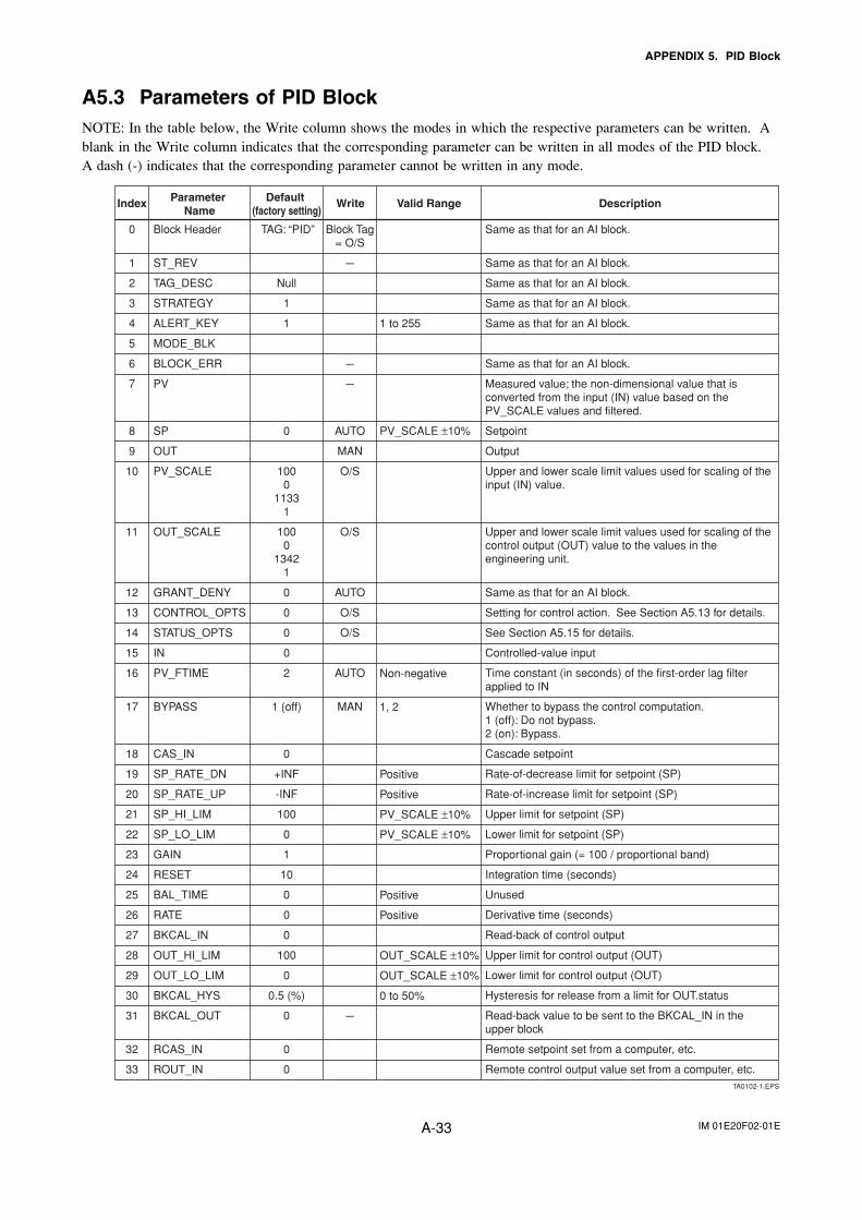
IM 01E20F02-01EA-33
APPENDIX 5. PID Block
A5.3 Parameters of PID BlockNOTE: In the table below, the Write column shows the modes in which the respective parameters can be written. Ablank in the Write column indicates that the corresponding parameter can be written in all modes of the PID block.A dash (-) indicates that the corresponding parameter cannot be written in any mode.
0
1
2
3
4
5
6
7
8
9
10
11
12
13
14
15
16
17
18
19
20
21
22
23
24
25
26
27
28
29
30
31
32
33
Index Default (factory setting)
Parameter Name
Valid RangeWrite Description
Block Header
ST_REV
TAG_DESC
STRATEGY
ALERT_KEY
MODE_BLK
BLOCK_ERR
PV
SP
OUT
PV_SCALE
OUT_SCALE
GRANT_DENY
CONTROL_OPTS
STATUS_OPTS
IN
PV_FTIME
BYPASS
CAS_IN
SP_RATE_DN
SP_RATE_UP
SP_HI_LIM
SP_LO_LIM
GAIN
RESET
BAL_TIME
RATE
BKCAL_IN
OUT_HI_LIM
OUT_LO_LIM
BKCAL_HYS
BKCAL_OUT
RCAS_IN
ROUT_IN
TAG: “PID”
Null
1
1
0
1000
11331
1000
13421
0
0
0
0
2
1 (off)
0
+INF
-INF
100
0
1
10
0
0
0
100
0
0.5 (%)
0
0
0
Block Tag= O/S
---
---
---
AUTO
MAN
O/S
O/S
AUTO
O/S
O/S
AUTO
MAN
---
Same as that for an AI block.
Same as that for an AI block.
Same as that for an AI block.
Same as that for an AI block.
Same as that for an AI block.
Same as that for an AI block.
Measured value; the non-dimensional value that is converted from the input (IN) value based on the PV_SCALE values and filtered.
Setpoint
Output
Upper and lower scale limit values used for scaling of the input (IN) value.
Upper and lower scale limit values used for scaling of the control output (OUT) value to the values in the engineering unit.
Same as that for an AI block.
Setting for control action. See Section A5.13 for details.
See Section A5.15 for details.
Controlled-value input
Time constant (in seconds) of the first-order lag filter applied to IN
Whether to bypass the control computation. 1 (off): Do not bypass.2 (on): Bypass.
Cascade setpoint
Rate-of-decrease limit for setpoint (SP)
Rate-of-increase limit for setpoint (SP)
Upper limit for setpoint (SP)
Lower limit for setpoint (SP)
Proportional gain (= 100 / proportional band)
Integration time (seconds)
Unused
Derivative time (seconds)
Read-back of control output
Upper limit for control output (OUT)
Lower limit for control output (OUT)
Hysteresis for release from a limit for OUT.status
Read-back value to be sent to the BKCAL_IN in the upper block
Remote setpoint set from a computer, etc.
Remote control output value set from a computer, etc.
1 to 255
PV_SCALE ±10%
Non-negative
1, 2
Positive
Positive
PV_SCALE ±10%
PV_SCALE ±10%
Positive
Positive
OUT_SCALE ±10%
OUT_SCALE ±10%
0 to 50%
TA0102-1.EPS
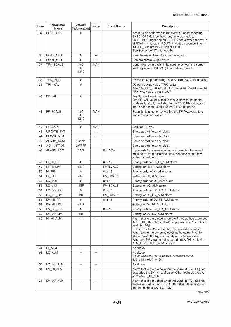
IM 01E20F02-01EA-34
APPENDIX 5. PID Block
34
35
36
37
38
39
40
41
42
43
44
45
46
47
48
49
50
51
52
53
54
55
56
57
58
59
60
61
62
63
64
65
Index Default (factory setting)
Parameter Name
Valid RangeWrite Description
SHED_OPT
RCAS_OUT
ROUT_OUT
TRK_SCALE
TRK_IN_D
TRK_VAL
FF_VAL
FF_SCALE
FF_GAIN
UPDATE_EVT
BLOCK_ALM
ALARM_SUM
ACK_OPTION
ALARM_HYS
HI_HI_PRI
HI_HI_LIM
HI_PRI
HI_LIM
LO_PRI
LO_LIM
LO_LO_PRI
LO_LO_LIM
DV_HI_PRI
DV_HI_LIM
DV_LO_PRI
DV_LO_LIM
HI_HI_ALM
HI_ALM
LO_ALM
LO_LO_ALM
DV_HI_ALM
DV_LO_ALM
0
0
0
1000
13421
0
0
0
1000
13421
0
Enable
0xFFFF
0.5%
0
+INF
0
+INF
0
-INF
0
-INF
0
+INF
0
-INF
---
---
---
---
---
---
---
---
MAN
MAN
MAN
---
---
---
---
---
---
---
---
Action to be performed in the event of mode shedding.SHED_OPT defines the changes to be made to MODE.BLK.target and MODE.BLK.actual when the value of RCAS_IN.status or ROUT_IN.status becomes Bad if .MODE_BLK.actual = RCas or ROut. See Section A5.17.1 for details.
Remote setpoint sent to a computer, etc.
Remote control output value
Upper and lower scale limits used to convert the output tracking value (TRK_VAL) to non-dimensional.
Switch for output tracking. See Section A5.12 for details.
Output tracking value (TRK_VAL)When MODE_BLK.actual = LO, the value scaled from the TRK_VAL value is set in OUT.
Feedforward input value. The FF_VAL value is scaled to a value with the same scale as for OUT, multiplied by the FF_GAIN value, and then added to the output of the PID computation.
Scale limits used for converting the FF_VAL value to a non-dimensional value.
Gain for FF_VAL
Same as that for an AI block.
Same as that for an AI block.
Same as that for an AI block.
Same as that for an AI block.
Hysteresis for alarm detection and resetting to prevent each alarm from occurring and recovering repeatedly within a short time.
Priority order of HI_HI_ALM alarm
Setting for HI_HI_ALM alarm
Priority order of HI_ALM alarm
Setting for HI_ALM alarm
Priority order of LO_ALM alarm
Setting for LO_ALM alarm
Priority order of LO_LO_ALM alarm
Setting for LO_LO_ALM alarm
Priority order of DV_HI_ALM alarm
Setting for DV_HI_ALM alarm
Priority order of DV_LO_ALM alarm
Setting for DV_LO_ALM alarm
Alarm that is generated when the PV value has exceeded the HI_HI_LIM value and whose priority order* is defined in HI_HI_PRI. * Priority order: Only one alarm is generated at a time. When two or more alarms occur at the same time, the alarm having the highest priority order is generated. When the PV value has decreased below [HI_HI_LIM - ALM_HYS], HI_HI_ALM is reset.
As above
As aboveReset when the PV value has increased above [LO_LIM + ALM_HYS].
As above
Alarm that is generated when the value of [PV - SP] has exceeded the DV_HI_LIM value. Other features are the same as HI_HI_ALM.
Alarm that is generated when the value of [PV - SP] has decreased below the DV_LO_LIM value. Other features are the same as LO_LO_ALM.
0 to 50%
0 to 15
PV_SCALE
0 to 15
PV_SCALE
0 to 15
PV_SCALE
0 to 15
PV_SCALE
0 to 15
0 to 15
TA0102-2.EPS
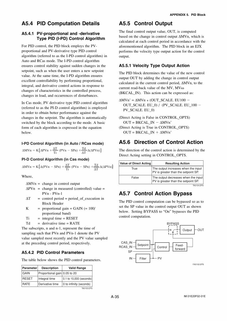
IM 01E20F02-01EA-35
APPENDIX 5. PID Block
A5.4 PID Computation Details
A5.4.1 PV-proportional and -derivativeType PID (I-PD) Control Algorithm
For PID control, the PID block employs the PV-proportional and PV-derivative type PID controlalgorithm (referred to as the I-PD control algorithm) inAuto and RCas mode. The I-PD control algorithmensures control stability against sudden changes in thesetpoint, such as when the user enters a new setpointvalue. At the same time, the I-PD algorithm ensuresexcellent controllability by performing proportional,integral, and derivative control actions in response tochanges of characteristics in the controlled process,changes in load, and occurrences of disturbances.
In Cas mode, PV derivative type PID control algorithm(referred to as the PI-D control algorithm) is employedin order to obtain better performance against thechanges in the setpoint. The algorithm is automaticallyswitched by the block according to the mode. A basicform of each algorithm is expressed in the equationbelow.
∆MVn � K ∆PVn � (PVn � SPn) � ∆(∆PVn)∆TTi
Td∆T{ }
I-PD Control Algorithm (in Auto / RCas mode)
∆MVn � K ∆(PVn � SPn) � (PVn � SPn) � ∆(∆PVn)∆TTi
Td∆T
{ }PI-D Control Algorithm (in Cas mode)
Where,
∆MVn = change in control output∆PVn = change in measured (controlled) value =
PVn - PVn-1∆T = control period = period_of_execution in
Block HeaderK = proportional gain = GAIN (= 100/
proportional band)Ti = integral time = RESETTd = derivative time = RATE
The subscripts, n and n-1, represent the time ofsampling such that PVn and PVn-1 denote the PVvalue sampled most recently and the PV value sampledat the preceding control period, respectively.
A5.4.2 PID Control Parameters
The table below shows the PID control parameters.
Parameter Description Valid Range
GAIN
RESET
RATE
Proportional gain
Integral time
Derivative time
0.05 to 20
0.1 to 10,000 (seconds)
0 to infinity (seconds)TA0103.EPS
A5.5 Control OutputThe final control output value, OUT, is computedbased on the change in control output ∆MVn, which iscalculated at each control period in accordance with theaforementioned algorithm. The PID block in an EJXperforms the velocity type output action for the controloutput.
A5.5.1 Velocity Type Output Action
The PID block determines the value of the new controloutput OUT by adding the change in control outputcalculated in the current control period, ∆MVn, to thecurrent read-back value of the MV, MVRB
(BKCAL_IN). This action can be expressed as:
∆MVn’ = ∆MVn * (OUT_SCALE. EU100 �OUT_SCALE. EU_0) / (PV_SCALE. EU_100 �PV_SCALE. EU_0)
(Direct Acting is False in CONTROL_OPTS)OUT = BKCAL_IN � ∆MVn’
(Direct Acting is True in CONTROL_OPTS)OUT = BKCAL_IN � ∆MVn’
A5.6 Direction of Control ActionThe direction of the control action is determined by theDirect Acting setting in CONTROL_OPTS.
Value of Direct Acting Resulting Action
The output increases when the input PV is greater than the setpoint SP.
The output decreases when the input PV is greater than the setpoint SP.
True
False
TA0104.EPS
A5.7 Control Action BypassThe PID control computation can be bypassed so as toset the SP value in the control output OUT as shownbelow. Setting BYPASS to “On” bypasses the PIDcontrol computation.
SetpointControl
Feed- forward
CAS_IN
FilterIN PV
BYPASS
SP
RCAS_IN
Output OUT
FA0102.EPS
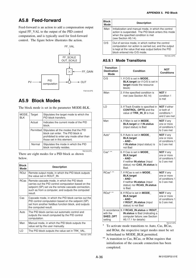
IM 01E20F02-01EA-36
APPENDIX 5. PID Block
A5.8 Feed-forwardFeed-forward is an action to add a compensation outputsignal FF_VAL to the output of the PID controlcomputation, and is typically used for feed-forwardcontrol. The figure below illustrates the action.
PID computation
FF_SCALEOUT_SCALE
PV OUT
FF_VAL
FF_GAIN
FA0103.EPS
A5.9 Block ModesThe block mode is set in the parameter MODE-BLK.
Stipulates the target mode to which the PID block transfers.
Indicates the current mode of the PID block.
Stipulates all the modes that the PID block can enter. The PID block is prohibited to enter any mode other than those set in this element.
Stipulates the mode in which the PID block normally resides.
MODE_BLK
Target
Actual
Permitted
Normal
TA0105.EPS
There are eight modes for a PID block as shownbelow.
Block Mode
Description
Remote output mode, in which the PID block outputs the value set in ROUT_IN.
Remote cascade mode, in which the PID block carries out the PID control computation based on the setpoint (SP) set via the remote cascade connection, such as from a computer, and outputs the computed result.
Cascade mode, in which the PID block carries out the PID control computation based on the setpoint (SP) set from another fieldbus function block, and outputs the computed result.
The PID block carries out automatic control and outputs the result computed by the PID control computation.
Manual mode, in which the PID block outputs the value set by the user manually.
The PID block outputs the value set in TRK_VAL.
ROut
RCas
Cas
Auto
Man
LOTA0106-1.EPS
Block Mode
Description
Initialization and manual mode, in which the control action is suspended. The PID block enters this mode when the specified condition is met (see Section A5.14).
Out of service mode, in which neither the control computation nor action is carried out, and the output is kept at the value that was output before the PID block entered into O/S mode.
IMan
O/S
TA0106-2.EPS
A5.9.1 Mode Transitions
Transition Destination
ModeCondition NOT
Conditions
1. If O/S is set in MODE_ BLK.target (or if O/S is set in target inside the resource block)
2. If the specified condition is met (see Section A5.14)
3. If Track Enable is specified in CONTROL_OPTS and the value of TRK_IN_D is true
4. If Man is set in MODE_ BLK.target or if IN.status (input status) is Bad
5. If Auto is set in MODE_ BLK.target - AND - if IN.status (input status) is not Bad
6. If Cas is set in MODE_ BLK.target - AND - if neither IN.status (input status) nor CAS_IN.status is Bad.
7. If RCas is set in MODE_ BLK.target - AND - if neither IN.status (input status) nor RCAS_IN.status is Bad.
8. If ROut is set in MODE_ BLK.target - AND - if ROUT_IN.status (input status) is not Bad
9. If RCAS_IN.status or ROUT_ IN.status is Bad (indicating a computer failure; see Section A5.17.1 for details)
NOT if condition 1 is met
NOT if either or both of conditions 1 and 2 are met
NOT if any one or more of conditions 1 to 3 are met
NOT if any one or more of conditions 1 to 3 are met
NOT if any one or more of conditions 1 to 3 are met
NOT if any one or more of conditions 1 to 3 are met.
NOT if any one or more of conditions 1 to 3 are met.
O/S
IMan
LO
Man
Auto*
Cas*, **
RCas*, **
ROut*, **
In accordance with the SHED_OPT setting
TA0107.EPS
* To activate mode transitions to Auto, Cas, RCas,and ROut, the respective target modes must be setbeforehand to MODE_BLK.permitted.
** A transition to Cas, RCas, or ROut requires thatinitialization of the cascade connection has beencompleted.
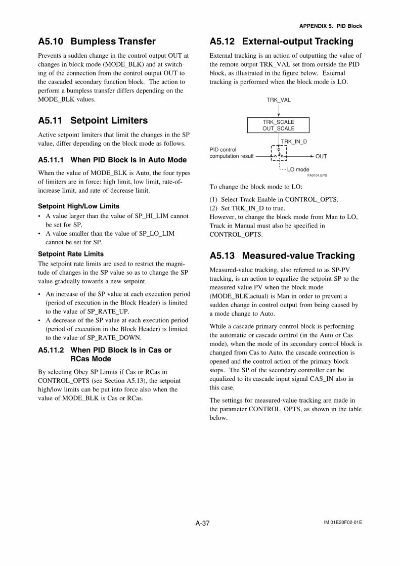
IM 01E20F02-01EA-37
APPENDIX 5. PID Block
A5.10 Bumpless TransferPrevents a sudden change in the control output OUT atchanges in block mode (MODE_BLK) and at switch-ing of the connection from the control output OUT tothe cascaded secondary function block. The action toperform a bumpless transfer differs depending on theMODE_BLK values.
A5.11 Setpoint LimitersActive setpoint limiters that limit the changes in the SPvalue, differ depending on the block mode as follows.
A5.11.1 When PID Block Is in Auto Mode
When the value of MODE_BLK is Auto, the four typesof limiters are in force: high limit, low limit, rate-of-increase limit, and rate-of-decrease limit.
Setpoint High/Low Limits• A value larger than the value of SP_HI_LIM cannot
be set for SP.• A value smaller than the value of SP_LO_LIM
cannot be set for SP.
Setpoint Rate LimitsThe setpoint rate limits are used to restrict the magni-tude of changes in the SP value so as to change the SPvalue gradually towards a new setpoint.
• An increase of the SP value at each execution period(period of execution in the Block Header) is limitedto the value of SP_RATE_UP.
• A decrease of the SP value at each execution period(period of execution in the Block Header) is limitedto the value of SP_RATE_DOWN.
A5.11.2 When PID Block Is in Cas orRCas Mode
By selecting Obey SP Limits if Cas or RCas inCONTROL_OPTS (see Section A5.13), the setpointhigh/low limits can be put into force also when thevalue of MODE_BLK is Cas or RCas.
A5.12 External-output TrackingExternal tracking is an action of outputting the value ofthe remote output TRK_VAL set from outside the PIDblock, as illustrated in the figure below. Externaltracking is performed when the block mode is LO.
TRK_SCALEOUT_SCALE
TRK_VAL
OUT
TRK_IN_D
LO mode
PID control computation result
FA0104.EPS
To change the block mode to LO:
(1) Select Track Enable in CONTROL_OPTS.(2) Set TRK_IN_D to true.However, to change the block mode from Man to LO,Track in Manual must also be specified inCONTROL_OPTS.
A5.13 Measured-value TrackingMeasured-value tracking, also referred to as SP-PVtracking, is an action to equalize the setpoint SP to themeasured value PV when the block mode(MODE_BLK.actual) is Man in order to prevent asudden change in control output from being caused bya mode change to Auto.
While a cascade primary control block is performingthe automatic or cascade control (in the Auto or Casmode), when the mode of its secondary control block ischanged from Cas to Auto, the cascade connection isopened and the control action of the primary blockstops. The SP of the secondary controller can beequalized to its cascade input signal CAS_IN also inthis case.
The settings for measured-value tracking are made inthe parameter CONTROL_OPTS, as shown in the tablebelow.
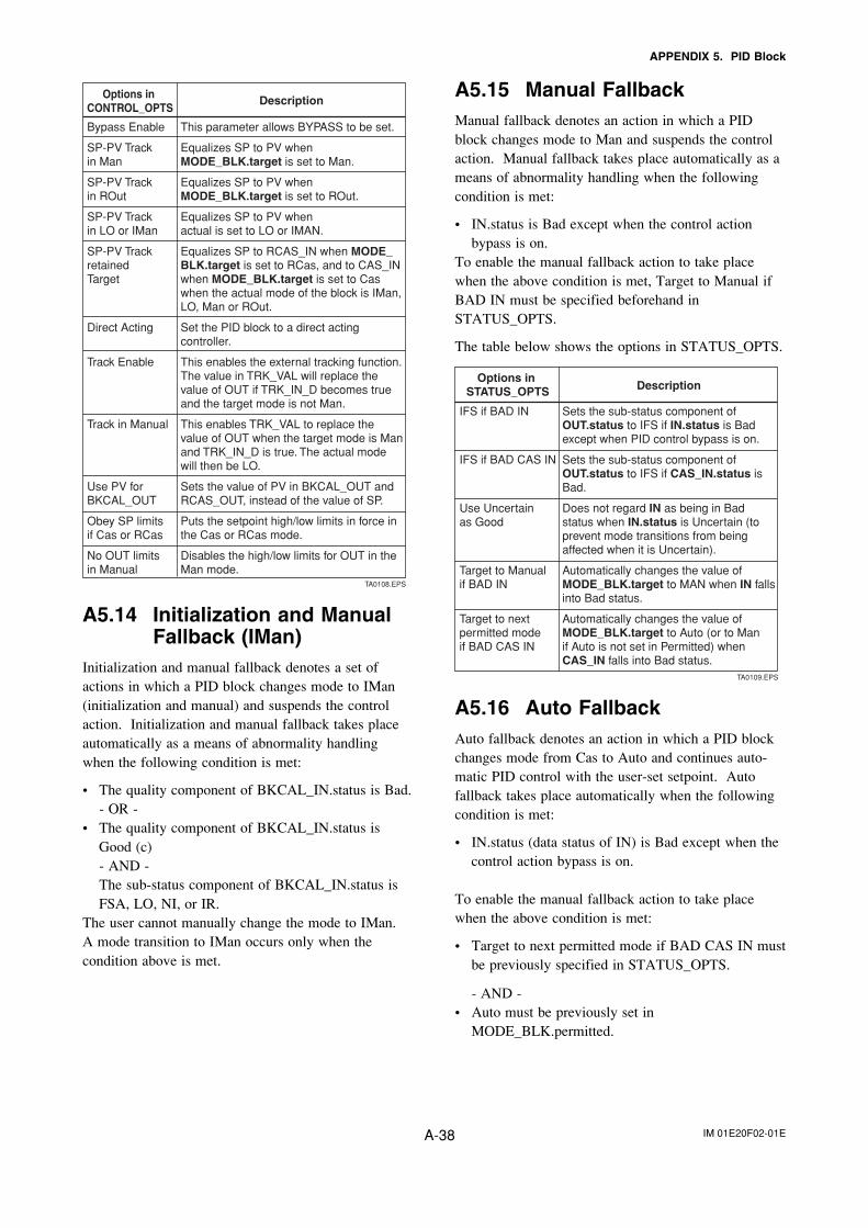
IM 01E20F02-01EA-38
APPENDIX 5. PID Block
Options in CONTROL_OPTS
Description
This parameter allows BYPASS to be set.
Equalizes SP to PV when MODE_BLK.target is set to Man.
Equalizes SP to PV when MODE_BLK.target is set to ROut.
Equalizes SP to PV when actual is set to LO or IMAN.
Equalizes SP to RCAS_IN when MODE_BLK.target is set to RCas, and to CAS_IN when MODE_BLK.target is set to Caswhen the actual mode of the block is IMan, LO, Man or ROut.
Set the PID block to a direct acting controller.
This enables the external tracking function.The value in TRK_VAL will replace the value of OUT if TRK_IN_D becomes true and the target mode is not Man.
This enables TRK_VAL to replace the value of OUT when the target mode is Man and TRK_IN_D is true. The actual mode will then be LO.
Sets the value of PV in BKCAL_OUT and RCAS_OUT, instead of the value of SP.
Puts the setpoint high/low limits in force in the Cas or RCas mode.
Disables the high/low limits for OUT in the Man mode.
Bypass Enable
SP-PV Track in Man
SP-PV Track in ROut
SP-PV Track in LO or IMan
SP-PV Track retained Target
Direct Acting
Track Enable
Track in Manual
Use PV for BKCAL_OUT
Obey SP limits if Cas or RCas
No OUT limits in Manual
TA0108.EPS
A5.14 Initialization and ManualFallback (IMan)
Initialization and manual fallback denotes a set ofactions in which a PID block changes mode to IMan(initialization and manual) and suspends the controlaction. Initialization and manual fallback takes placeautomatically as a means of abnormality handlingwhen the following condition is met:
• The quality component of BKCAL_IN.status is Bad.- OR -
• The quality component of BKCAL_IN.status isGood (c)- AND -The sub-status component of BKCAL_IN.status isFSA, LO, NI, or IR.
The user cannot manually change the mode to IMan.A mode transition to IMan occurs only when thecondition above is met.
A5.15 Manual FallbackManual fallback denotes an action in which a PIDblock changes mode to Man and suspends the controlaction. Manual fallback takes place automatically as ameans of abnormality handling when the followingcondition is met:
• IN.status is Bad except when the control actionbypass is on.
To enable the manual fallback action to take placewhen the above condition is met, Target to Manual ifBAD IN must be specified beforehand inSTATUS_OPTS.
The table below shows the options in STATUS_OPTS.
Options in STATUS_OPTS Description
Sets the sub-status component of OUT.status to IFS if IN.status is Bad except when PID control bypass is on.
Sets the sub-status component of OUT.status to IFS if CAS_IN.status is Bad.
Does not regard IN as being in Bad status when IN.status is Uncertain (to prevent mode transitions from being affected when it is Uncertain).
Automatically changes the value of MODE_BLK.target to MAN when IN falls into Bad status.
Automatically changes the value of MODE_BLK.target to Auto (or to Man if Auto is not set in Permitted) when CAS_IN falls into Bad status.
IFS if BAD IN
IFS if BAD CAS IN
Use Uncertain as Good
Target to Manual if BAD IN
Target to next permitted mode if BAD CAS IN
TA0109.EPS
A5.16 Auto FallbackAuto fallback denotes an action in which a PID blockchanges mode from Cas to Auto and continues auto-matic PID control with the user-set setpoint. Autofallback takes place automatically when the followingcondition is met:
• IN.status (data status of IN) is Bad except when thecontrol action bypass is on.
To enable the manual fallback action to take placewhen the above condition is met:
• Target to next permitted mode if BAD CAS IN mustbe previously specified in STATUS_OPTS.
- AND -• Auto must be previously set in
MODE_BLK.permitted.
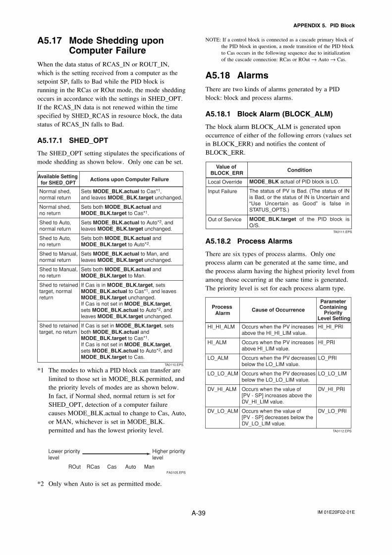
IM 01E20F02-01EA-39
APPENDIX 5. PID Block
A5.17 Mode Shedding uponComputer Failure
When the data status of RCAS_IN or ROUT_IN,which is the setting received from a computer as thesetpoint SP, falls to Bad while the PID block isrunning in the RCas or ROut mode, the mode sheddingoccurs in accordance with the settings in SHED_OPT.If the RCAS_IN data is not renewed within the timespecified by SHED_RCAS in resource block, the datastatus of RCAS_IN falls to Bad.
A5.17.1 SHED_OPT
The SHED_OPT setting stipulates the specifications ofmode shedding as shown below. Only one can be set.
Available Setting for SHED_OPT
Actions upon Computer Failure
Sets MODE_BLK.actual to Cas*1, and leaves MODE_BLK.target unchanged.
Sets both MODE_BLK.actual and MODE_BLK.target to Cas*1.
Sets MODE_BLK.actual to Auto*2, and leaves MODE_BLK.target unchanged.
Sets both MODE_BLK.actual and MODE_BLK.target to Auto*2.
Sets MODE_BLK.actual to Man, and leaves MODE_BLK.target unchanged.
Sets both MODE_BLK.actual and MODE_BLK.target to Man.
If Cas is in MODE_BLK.target, sets MODE_BLK.actual to Cas*1, and leaves MODE_BLK.target unchanged.If Cas is not set in MODE_BLK.target, sets MODE_BLK.actual to Auto*2, and leaves MODE_BLK.target unchanged.
If Cas is set in MODE_BLK.target, sets both MODE_BLK.actual and MODE_BLK.target to Cas*1. If Cas is not set in MODE_BLK.target, sets MODE_BLK.actual to Auto*2, and MODE_BLK.target to Cas.
Normal shed, normal return
Normal shed, no return
Shed to Auto, normal return
Shed to Auto, no return
Shed to Manual, normal return
Shed to Manual, no return
Shed to retained target, normal return
Shed to retained target, no return
TA0110.EPS
*1 The modes to which a PID block can transfer arelimited to those set in MODE_BLK.permitted, andthe priority levels of modes are as shown below.In fact, if Normal shed, normal return is set forSHED_OPT, detection of a computer failurecauses MODE_BLK.actual to change to Cas, Auto,or MAN, whichever is set in MODE_BLK.permitted and has the lowest priority level.
FA0105.EPS
Higher priority level
Lower prioritylevel
ROut RCas Cas Auto Man
*2 Only when Auto is set as permitted mode.
NOTE: If a control block is connected as a cascade primary block ofthe PID block in question, a mode transition of the PID blockto Cas occurs in the following sequence due to initializationof the cascade connection: RCas or ROut → Auto → Cas.
A5.18 AlarmsThere are two kinds of alarms generated by a PIDblock: block and process alarms.
A5.18.1 Block Alarm (BLOCK_ALM)
The block alarm BLOCK_ALM is generated uponoccurrence of either of the following errors (values setin BLOCK_ERR) and notifies the content ofBLOCK_ERR.
Value of BLOCK_ERR Condition
Local Override
Input Failure
Out of Service
TA0111.EPS
MODE_BLK actual of PID block is LO.
The status of PV is Bad. (The status of IN is Bad, or the status of IN is Uncertain and “Use Uncertain as Good” is false in STATUS_OPTS.)
MODE_BLK.target of the PID block is O/S.
A5.18.2 Process Alarms
There are six types of process alarms. Only oneprocess alarm can be generated at the same time, andthe process alarm having the highest priority level fromamong those occurring at the same time is generated.The priority level is set for each process alarm type.
Parameter Containing
Priority Level Setting
Cause of OccurrenceProcess Alarm
Occurs when the PV increases above the HI_HI_LIM value.
Occurs when the PV increases above HI_LIM value.
Occurs when the PV decreases below the LO_LIM value.
Occurs when the PV decreases below the LO_LO_LIM value.
Occurs when the value of [PV - SP] increases above the DV_HI_LIM value.
Occurs when the value of [PV - SP] decreases below the DV_LO_LIM value.
HI_HI_PRI
HI_PRI
LO_PRI
LO_LO_LIM
DV_HI_PRI
DV_LO_PRI
HI_HI_ALM
HI_ALM
LO_ALM
LO_LO_ALM
DV_HI_ALM
DV_LO_ALM
TA0112.EPS
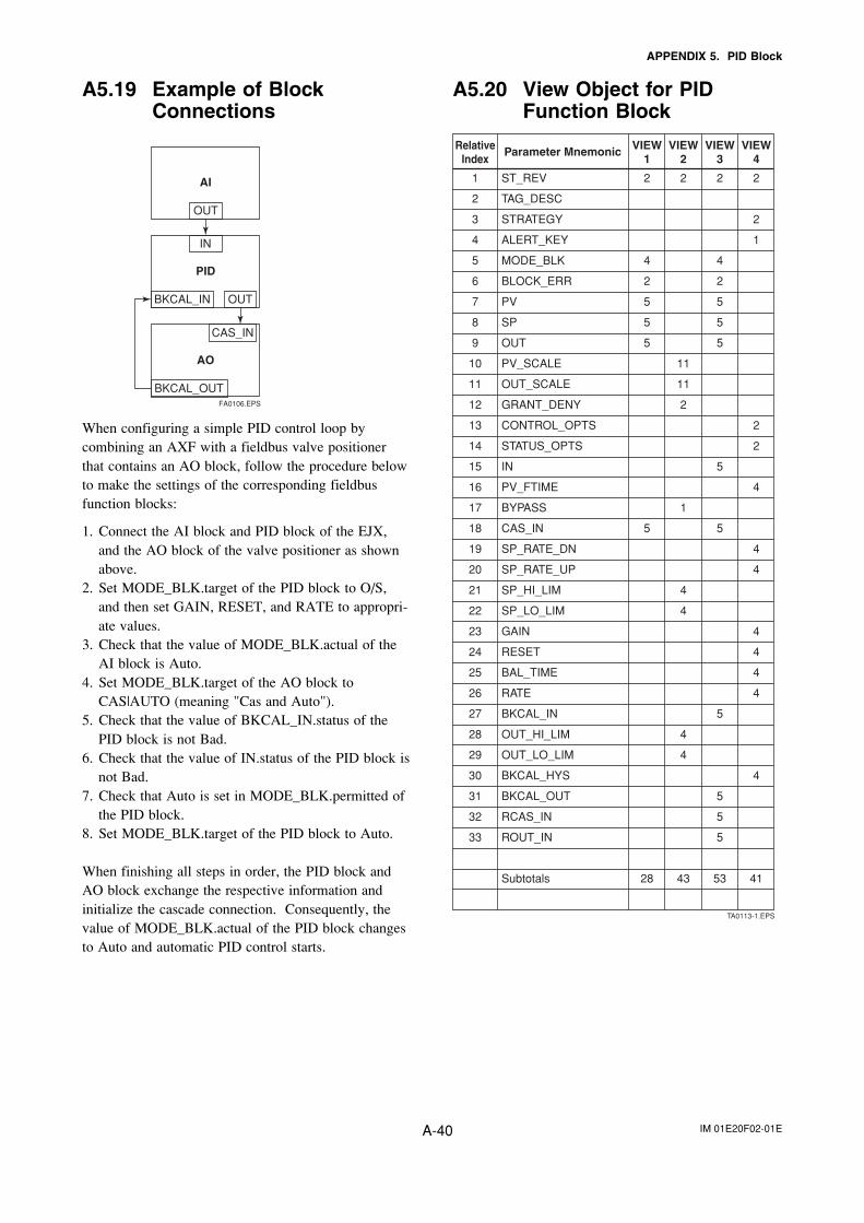
IM 01E20F02-01EA-40
APPENDIX 5. PID Block
A5.19 Example of BlockConnections
PID
BKCAL_IN OUT
IN
AO
BKCAL_OUT
CAS_IN
AI
OUT
FA0106.EPS
When configuring a simple PID control loop bycombining an AXF with a fieldbus valve positionerthat contains an AO block, follow the procedure belowto make the settings of the corresponding fieldbusfunction blocks:
1. Connect the AI block and PID block of the EJX,and the AO block of the valve positioner as shownabove.
2. Set MODE_BLK.target of the PID block to O/S,and then set GAIN, RESET, and RATE to appropri-ate values.
3. Check that the value of MODE_BLK.actual of theAI block is Auto.
4. Set MODE_BLK.target of the AO block toCAS|AUTO (meaning "Cas and Auto").
5. Check that the value of BKCAL_IN.status of thePID block is not Bad.
6. Check that the value of IN.status of the PID block isnot Bad.
7. Check that Auto is set in MODE_BLK.permitted ofthe PID block.
8. Set MODE_BLK.target of the PID block to Auto.
When finishing all steps in order, the PID block andAO block exchange the respective information andinitialize the cascade connection. Consequently, thevalue of MODE_BLK.actual of the PID block changesto Auto and automatic PID control starts.
A5.20 View Object for PIDFunction Block
VIEW4
RelativeIndex
Parameter Mnemonic
ST_REV
TAG_DESC
STRATEGY
ALERT_KEY
MODE_BLK
BLOCK_ERR
PV
SP
OUT
PV_SCALE
OUT_SCALE
GRANT_DENY
CONTROL_OPTS
STATUS_OPTS
IN
PV_FTIME
BYPASS
CAS_IN
SP_RATE_DN
SP_RATE_UP
SP_HI_LIM
SP_LO_LIM
GAIN
RESET
BAL_TIME
RATE
BKCAL_IN
OUT_HI_LIM
OUT_LO_LIM
BKCAL_HYS
BKCAL_OUT
RCAS_IN
ROUT_IN
Subtotals
2
2
1
2
2
4
4
4
4
4
4
4
4
41
VIEW3
2
4
2
5
5
5
5
5
5
5
5
5
53
VIEW2
2
11
11
2
1
4
4
4
4
43
VIEW1
2
4
2
5
5
5
5
28
1
2
3
4
5
6
7
8
9
10
11
12
13
14
15
16
17
18
19
20
21
22
23
24
25
26
27
28
29
30
31
32
33
TA0113-1.EPS
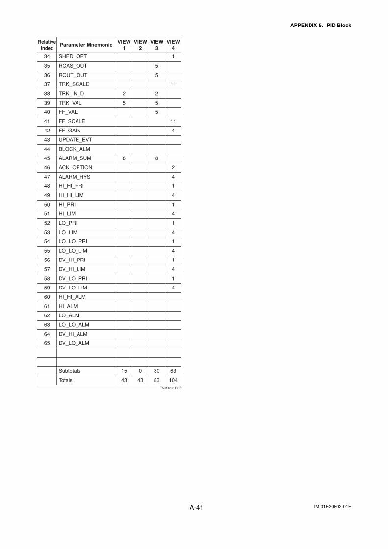
IM 01E20F02-01EA-41
APPENDIX 5. PID Block
VIEW4
RelativeIndex
Parameter Mnemonic
SHED_OPT
RCAS_OUT
ROUT_OUT
TRK_SCALE
TRK_IN_D
TRK_VAL
FF_VAL
FF_SCALE
FF_GAIN
UPDATE_EVT
BLOCK_ALM
ALARM_SUM
ACK_OPTION
ALARM_HYS
HI_HI_PRI
HI_HI_LIM
HI_PRI
HI_LIM
LO_PRI
LO_LIM
LO_LO_PRI
LO_LO_LIM
DV_HI_PRI
DV_HI_LIM
DV_LO_PRI
DV_LO_LIM
HI_HI_ALM
HI_ALM
LO_ALM
LO_LO_ALM
DV_HI_ALM
DV_LO_ALM
Subtotals
Totals
1
11
11
4
2
4
1
4
1
4
1
4
1
4
1
4
1
4
63
104
VIEW3
5
5
2
5
5
8
30
83
VIEW2
VIEW1
2
5
8
15
43
0
43
34
35
36
37
38
39
40
41
42
43
44
45
46
47
48
49
50
51
52
53
54
55
56
57
58
59
60
61
62
63
64
65
TA0113-2.EPS
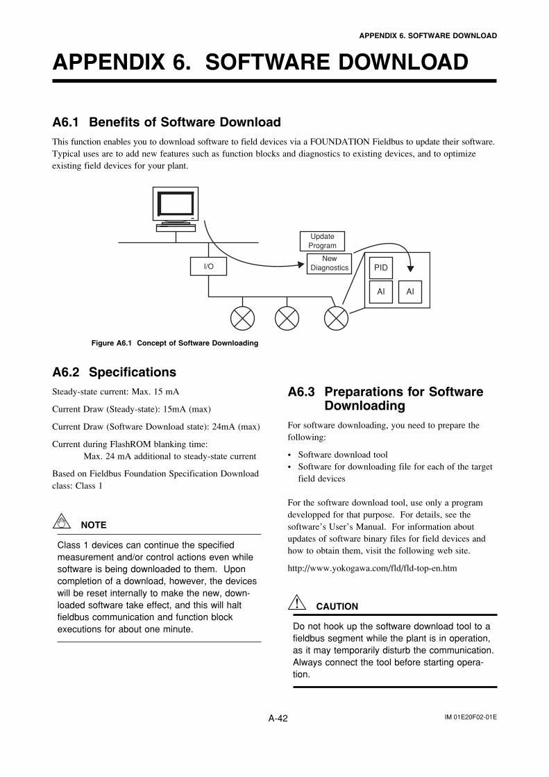
IM 01E20F02-01EA-42
APPENDIX 6. SOFTWARE DOWNLOAD
APPENDIX 6. SOFTWARE DOWNLOAD
A6.2 SpecificationsSteady-state current: Max. 15 mA
Current Draw (Steady-state): 15mA (max)
Current Draw (Software Download state): 24mA (max)
Current during FlashROM blanking time:Max. 24 mA additional to steady-state current
Based on Fieldbus Foundation Specification Downloadclass: Class 1
NOTE
Class 1 devices can continue the specifiedmeasurement and/or control actions even whilesoftware is being downloaded to them. Uponcompletion of a download, however, the deviceswill be reset internally to make the new, down-loaded software take effect, and this will haltfieldbus communication and function blockexecutions for about one minute.
A6.3 Preparations for SoftwareDownloading
For software downloading, you need to prepare thefollowing:
• Software download tool• Software for downloading file for each of the target
field devices
For the software download tool, use only a programdevelopped for that purpose. For details, see thesoftware’s User’s Manual. For information aboutupdates of software binary files for field devices andhow to obtain them, visit the following web site.
http://www.yokogawa.com/fld/fld-top-en.htm
CAUTION
Do not hook up the software download tool to afieldbus segment while the plant is in operation,as it may temporarily disturb the communication.Always connect the tool before starting opera-tion.
A6.1 Benefits of Software DownloadThis function enables you to download software to field devices via a FOUNDATION Fieldbus to update their software.Typical uses are to add new features such as function blocks and diagnostics to existing devices, and to optimizeexisting field devices for your plant.
PID
AI AI
Update Program
New DiagnosticsI/O
Figure A6.1 Concept of Software Downloading
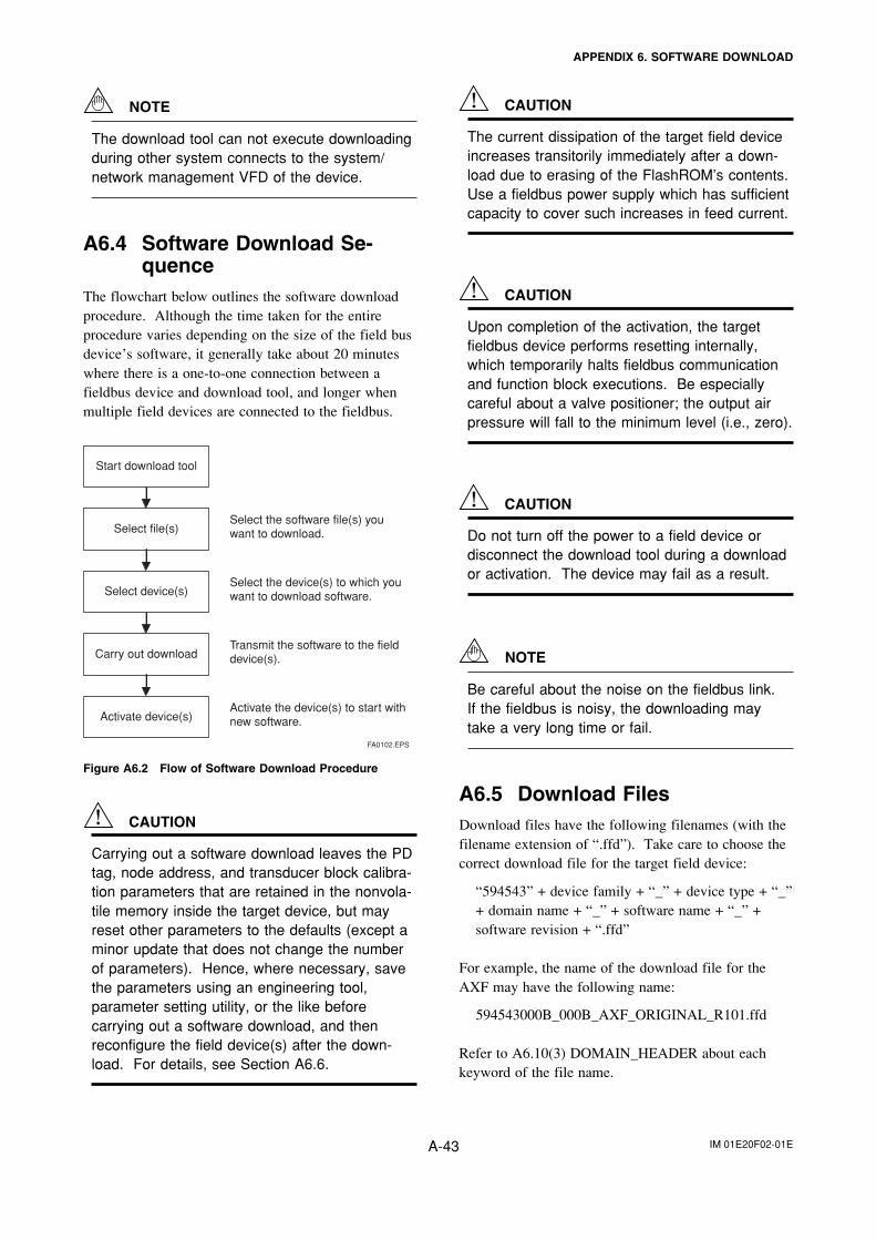
IM 01E20F02-01EA-43
APPENDIX 6. SOFTWARE DOWNLOAD
NOTE
The download tool can not execute downloadingduring other system connects to the system/network management VFD of the device.
A6.4 Software Download Se-quence
The flowchart below outlines the software downloadprocedure. Although the time taken for the entireprocedure varies depending on the size of the field busdevice’s software, it generally take about 20 minuteswhere there is a one-to-one connection between afieldbus device and download tool, and longer whenmultiple field devices are connected to the fieldbus.
FA0102.EPS
Start download tool
Select file(s)
Select device(s)
Carry out download
Activate device(s)
Select the software file(s) you want to download.
Select the device(s) to which you want to download software.
Transmit the software to the field device(s).
Activate the device(s) to start with new software.
Figure A6.2 Flow of Software Download Procedure
CAUTION
Carrying out a software download leaves the PDtag, node address, and transducer block calibra-tion parameters that are retained in the nonvola-tile memory inside the target device, but mayreset other parameters to the defaults (except aminor update that does not change the numberof parameters). Hence, where necessary, savethe parameters using an engineering tool,parameter setting utility, or the like beforecarrying out a software download, and thenreconfigure the field device(s) after the down-load. For details, see Section A6.6.
CAUTION
The current dissipation of the target field deviceincreases transitorily immediately after a down-load due to erasing of the FlashROM’s contents.Use a fieldbus power supply which has sufficientcapacity to cover such increases in feed current.
CAUTION
Upon completion of the activation, the targetfieldbus device performs resetting internally,which temporarily halts fieldbus communicationand function block executions. Be especiallycareful about a valve positioner; the output airpressure will fall to the minimum level (i.e., zero).
CAUTION
Do not turn off the power to a field device ordisconnect the download tool during a downloador activation. The device may fail as a result.
NOTE
Be careful about the noise on the fieldbus link.If the fieldbus is noisy, the downloading maytake a very long time or fail.
A6.5 Download FilesDownload files have the following filenames (with thefilename extension of “.ffd”). Take care to choose thecorrect download file for the target field device:
“594543” + device family + “_” + device type + “_”+ domain name + “_” + software name + “_” +software revision + “.ffd”
For example, the name of the download file for theAXF may have the following name:
594543000B_000B_AXF_ORIGINAL_R101.ffd
Refer to A6.10(3) DOMAIN_HEADER about eachkeyword of the file name.
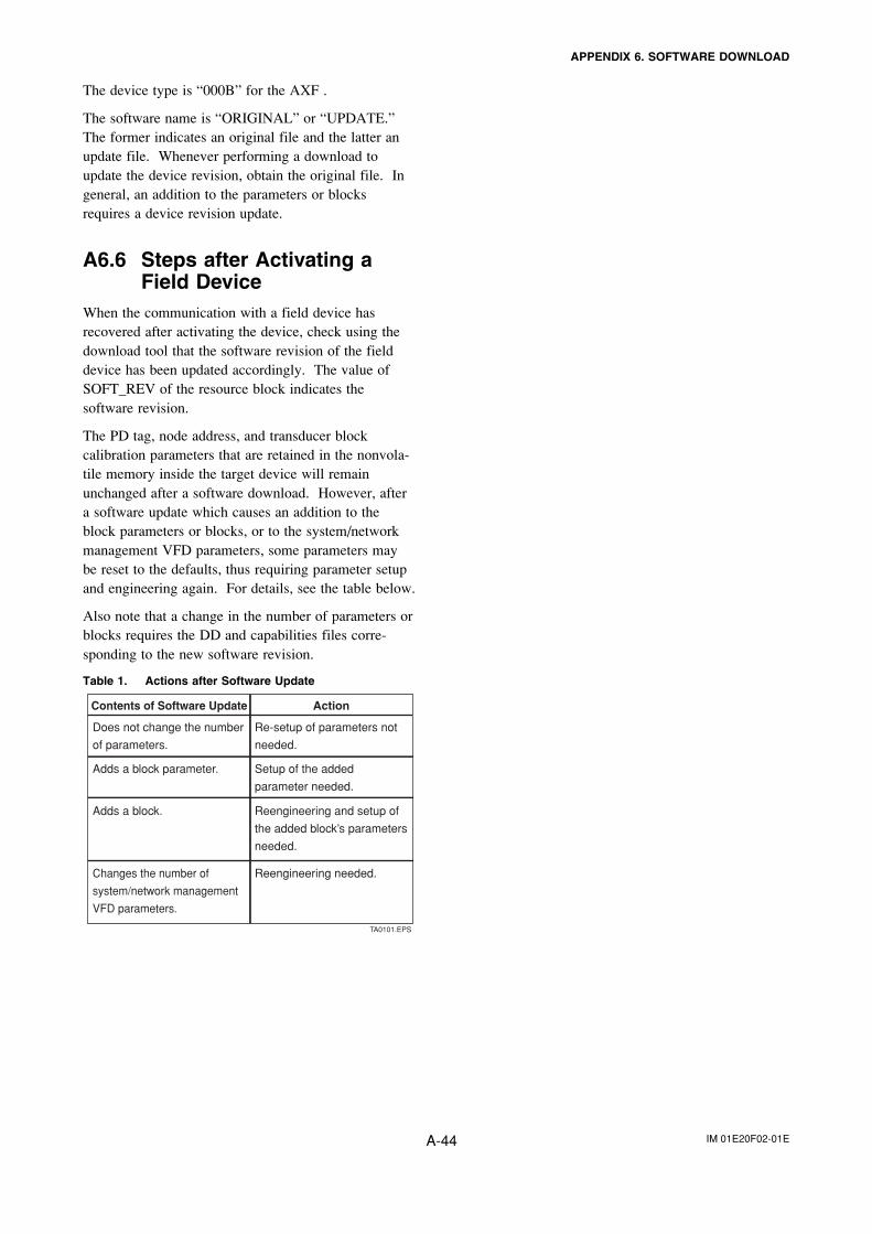
IM 01E20F02-01EA-44
APPENDIX 6. SOFTWARE DOWNLOAD
The device type is “000B” for the AXF .
The software name is “ORIGINAL” or “UPDATE.”The former indicates an original file and the latter anupdate file. Whenever performing a download toupdate the device revision, obtain the original file. Ingeneral, an addition to the parameters or blocksrequires a device revision update.
A6.6 Steps after Activating aField Device
When the communication with a field device hasrecovered after activating the device, check using thedownload tool that the software revision of the fielddevice has been updated accordingly. The value ofSOFT_REV of the resource block indicates thesoftware revision.
The PD tag, node address, and transducer blockcalibration parameters that are retained in the nonvola-tile memory inside the target device will remainunchanged after a software download. However, aftera software update which causes an addition to theblock parameters or blocks, or to the system/networkmanagement VFD parameters, some parameters maybe reset to the defaults, thus requiring parameter setupand engineering again. For details, see the table below.
Also note that a change in the number of parameters orblocks requires the DD and capabilities files corre-sponding to the new software revision.
Table 1. Actions after Software Update
TA0101.EPS
Adds a block.
Adds a block parameter.
Does not change the number
of parameters.
Changes the number of
system/network management
VFD parameters.
ActionContents of Software Update
Setup of the added
parameter needed.
Re-setup of parameters not
needed.
Reengineering and setup of
the added block’s parameters
needed.
Reengineering needed.
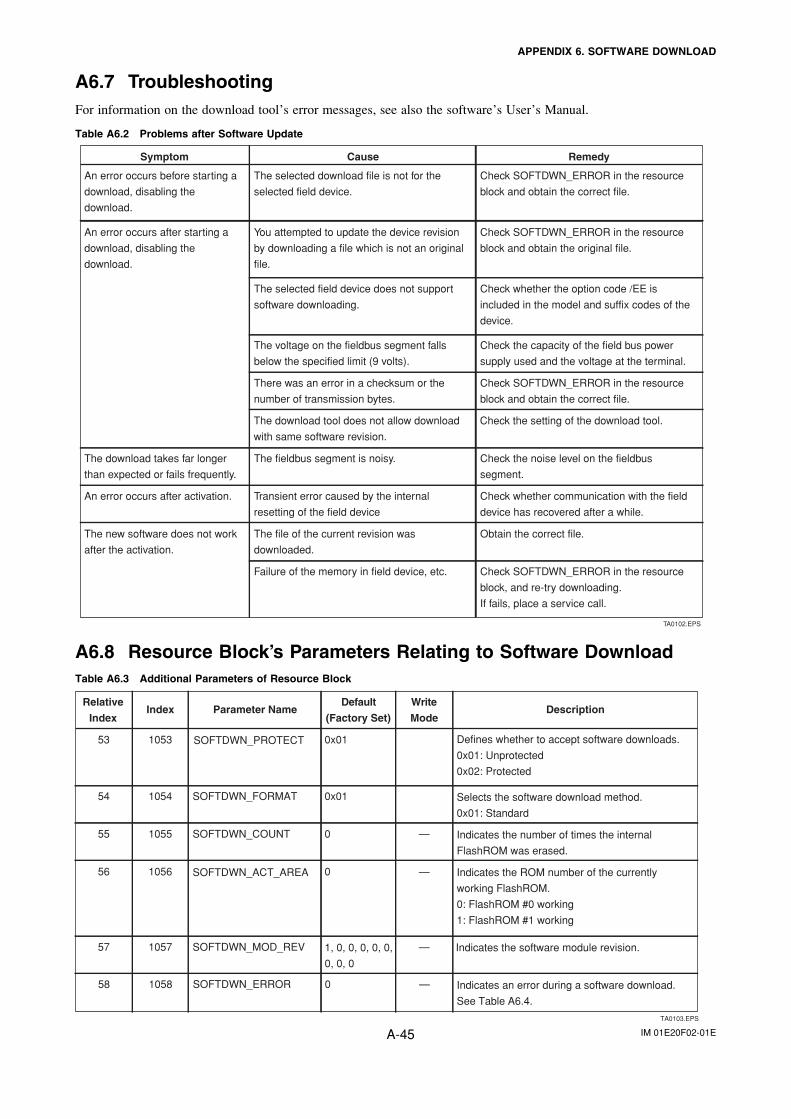
IM 01E20F02-01EA-45
APPENDIX 6. SOFTWARE DOWNLOAD
A6.7 TroubleshootingFor information on the download tool’s error messages, see also the software’s User’s Manual.
Table A6.2 Problems after Software Update
Symptom Cause Remedy
An error occurs before starting a
download, disabling the
download.
The selected download file is not for the
selected field device.
Check SOFTDWN_ERROR in the resource
block and obtain the correct file.
An error occurs after starting a
download, disabling the
download.
You attempted to update the device revision
by downloading a file which is not an original
file.
Check SOFTDWN_ERROR in the resource
block and obtain the original file.
The selected field device does not support
software downloading.
Check whether the option code /EE is
included in the model and suffix codes of the
device.
The voltage on the fieldbus segment falls
below the specified limit (9 volts).
Check the capacity of the field bus power
supply used and the voltage at the terminal.
There was an error in a checksum or the
number of transmission bytes.
Check SOFTDWN_ERROR in the resource
block and obtain the correct file.
The download takes far longer
than expected or fails frequently.
The fieldbus segment is noisy.
An error occurs after activation.
Check the noise level on the fieldbus
segment.
Transient error caused by the internal
resetting of the field device
Check whether communication with the field
device has recovered after a while.
The new software does not work
after the activation.
The file of the current revision was
downloaded.
Obtain the correct file.
Failure of the memory in field device, etc. Check SOFTDWN_ERROR in the resource
block, and re-try downloading.
If fails, place a service call.
TA0102.EPS
The download tool does not allow download
with same software revision.
Check the setting of the download tool.
A6.8 Resource Block’s Parameters Relating to Software DownloadTable A6.3 Additional Parameters of Resource Block
TA0103.EPS
Relative
IndexIndex Parameter Name
(Factory Set)
WriteDefault
ModeDescription
SOFTDWN_PROTECT
1, 0, 0, 0, 0, 0,
0, 0, 0
SOFTDWN_ACT_AREA
Defines whether to accept software downloads.
0x01: Unprotected
0x02: Protected
Selects the software download method.
0x01: Standard
Indicates the number of times the internal
FlashROM was erased.
Indicates the ROM number of the currently
working FlashROM.
0: FlashROM #0 working
1: FlashROM #1 working
Indicates the software module revision.
Indicates an error during a software download.
See Table A6.4.
1057
1055
1056
SOFTDWN_MOD_REV
—
—
—
1054
1053
0
SOFTDWN_FORMAT
SOFTDWN_COUNT
0x01
0x01
0
56
57
55
54
53
1058 —SOFTDWN_ERROR 058
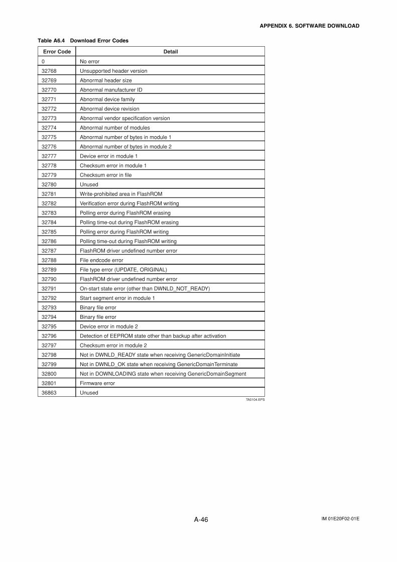
IM 01E20F02-01EA-46
APPENDIX 6. SOFTWARE DOWNLOAD
Table A6.4 Download Error Codes
TA0104.EPS
Error Code Detail
0
32768
32769
32770
32771
32772
32773
32774
32775
32776
32777
32778
32779
32780
32781
32782
32783
32784
32785
32786
32787
32788
32789
32790
32791
32792
32793
32794
32795
32796
32797
32798
32799
32800
32801
36863
No error
Unsupported header version
Abnormal header size
Abnormal manufacturer ID
Abnormal device family
Abnormal device revision
Abnormal vendor specification version
Abnormal number of modules
Abnormal number of bytes in module 1
Abnormal number of bytes in module 2
Device error in module 1
Checksum error in module 1
Checksum error in file
Unused
Write-prohibited area in FlashROM
Verification error during FlashROM writing
Polling error during FlashROM erasing
Polling time-out during FlashROM erasing
Polling error during FlashROM writing
Polling time-out during FlashROM writing
FlashROM driver undefined number error
File endcode error
File type error (UPDATE, ORIGINAL)
FlashROM driver undefined number error
On-start state error (other than DWNLD_NOT_READY)
Start segment error in module 1
Binary file error
Binary file error
Device error in module 2
Detection of EEPROM state other than backup after activation
Checksum error in module 2
Not in DWNLD_READY state when receiving GenericDomainInitiate
Not in DWNLD_OK state when receiving GenericDomainTerminate
Not in DOWNLOADING state when receiving GenericDomainSegment
Firmware error
Unused
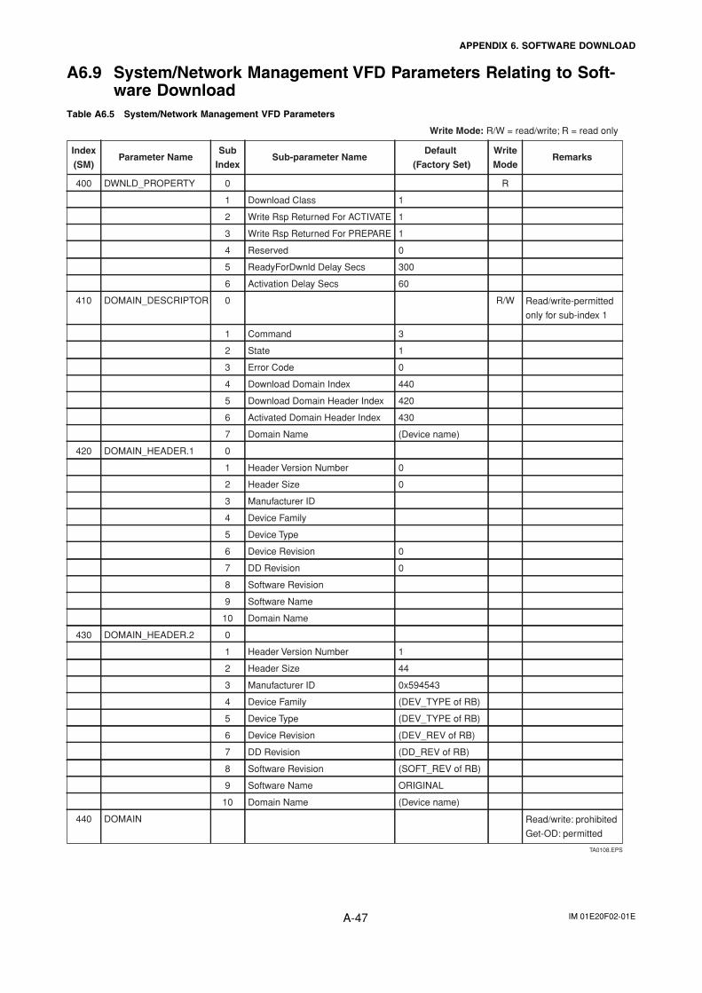
IM 01E20F02-01EA-47
APPENDIX 6. SOFTWARE DOWNLOAD
A6.9 System/Network Management VFD Parameters Relating to Soft-ware Download
Table A6.5 System/Network Management VFD Parameters
TA0108.EPS
Write Mode: R/W = read/write; R = read only
0
(Device name)
0
0
430
60
300
1
9
440
0
3
(DD_REV of RB)
ORIGINAL
(SOFT_REV of RB)
(DEV_REV of RB)
(Device name)
(DEV_TYPE of RB)
10 Domain Name
0
(DEV_TYPE of RB)
0x594543
1
44
420
DOMAIN_HEADER.1
DOMAIN_HEADER.2
0DWNLD_PROPERTY
1
1
1
DOMAIN_DESCRIPTOR
0
2
Activated Domain Header Index
Error Code
Domain Name
Download Domain Index
Download Domain Header Index
Header Size
Header Version Number
State
Reserved
ReadyForDwnld Delay Secs
Write Rsp Returned For PREPARE
Activation Delay Secs
Command
Manufacturer ID
Device Type
Write Rsp Returned For ACTIVATE
Device Family
Manufacturer ID
Device Revision
Software Name
Header Size
DD Revision
Software Revision
DD Revision
Software Revision
Device Revision
Device Family
Device Type
Header Version Number
Software Name
Domain Name
3
7
10
9
6
8
3
5
4
5
2
6
0
7
4
1
3
Download Class
5
6
0
4
3
1
2
2
6
5
7
0
1
1
4
8
Index
(SM)
440 DOMAIN Read/write: prohibited
Get-OD: permitted
420
430
Read/write-permitted
only for sub-index 1
RemarksParameter NameSub
Index
400
Sub-parameter Name
410 R/W
R
Write
Mode
Default
(Factory Set)
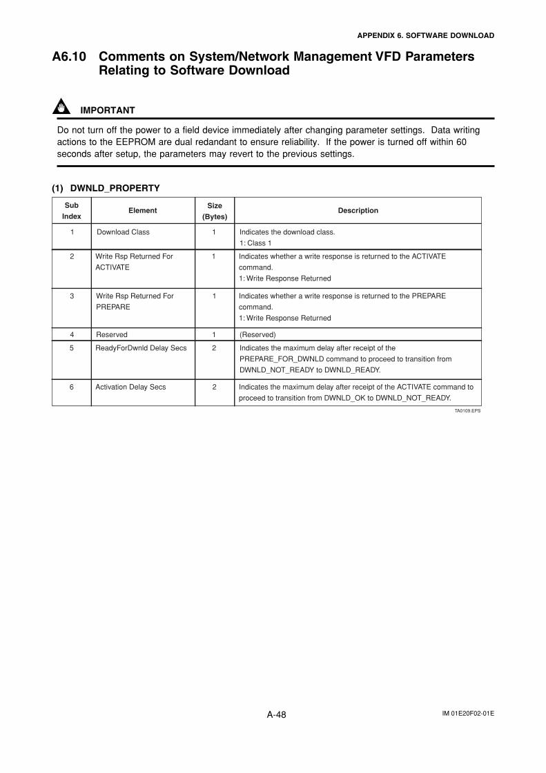
IM 01E20F02-01EA-48
APPENDIX 6. SOFTWARE DOWNLOAD
A6.10 Comments on System/Network Management VFD ParametersRelating to Software Download
IMPORTANT
Do not turn off the power to a field device immediately after changing parameter settings. Data writingactions to the EEPROM are dual redandant to ensure reliability. If the power is turned off within 60seconds after setup, the parameters may revert to the previous settings.
(1) DWNLD_PROPERTY
TA0109.EPS
Sub
IndexElement
Size
(Bytes)Description
Download Class Indicates the download class.
1: Class 1
1 1
Write Rsp Returned For
ACTIVATE
Indicates whether a write response is returned to the ACTIVATE
command.
1: Write Response Returned
12
Write Rsp Returned For
PREPARE
Indicates whether a write response is returned to the PREPARE
command.
1: Write Response Returned
Reserved (Reserved)
ReadyForDwnld Delay Secs Indicates the maximum delay after receipt of the
PREPARE_FOR_DWNLD command to proceed to transition from
DWNLD_NOT_READY to DWNLD_READY.
Activation Delay Secs Indicates the maximum delay after receipt of the ACTIVATE command to
proceed to transition from DWNLD_OK to DWNLD_NOT_READY.
1
1
2
26
5
4
3
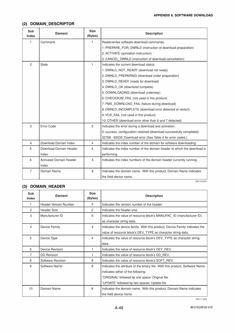
IM 01E20F02-01EA-49
APPENDIX 6. SOFTWARE DOWNLOAD
(2) DOMAIN_DESCRIPTOR
TA0110.EPS
Sub
IndexElement
Size
(Bytes)Description
Command Reads/writes software download commands.
1: PREPARE_FOR_DWNLD (instruction of download preparation)
2: ACTIVATE (activation instruction)
3: CANCEL_DWNLD (instruction of download cancellation)
1 1
12
2
4
4
6
5
4
3
Indicates the current download status.
1: DWNLD_NOT_READY (download not ready)
2: DWNLD_PREPARING (download under preparation)
3: DWNLD_READY (ready for download)
4: DWNLD_OK (download complete)
5: DOWNLOADING (download underway)
6: CHECKSUM_FAIL (not used in this product)
7: FMS_DOWNLOAD_FAIL (failure during download)
8: DWNLD_INCOMPLETE (download error detected at restart)
9: VCR_FAIL (not used in this product)
10: OTHER (download error other than 6 and 7 detected)
State
Error Code Indicates the error during a download and activation.
0: success, configuration retained (download successfully completed)
32768 - 65535: Download error (See Table 4 for error codes.)
Download Domain Index Indicates the index number of the domain for software downloading.
Download Domain Header
Index
Indicates the index number of the domain header to which the download is
performing.
Activated Domain Header
Index
Indicates the index numbers of the domain header currently running.
Indicates the domain name. With this product, Domain Name indicates
the field device name.
Domain Name7 8
4
(3) DOMAIN_HEADER
TA0111.EPS
Sub
IndexElement
Size
(Bytes)Description
Header Version Number Indicates the version number of the header. 1 2
22
6
4
4
6
5
4
3
Indicates the header size. Header Size
Manufacturer ID Indicates the value of resource block’s MANUFAC_ID (manufacturer ID)
as character string data.
Device Family Indicates the device family. With this product, Device Family indicates the
value of resource block’s DEV_TYPE as character string data.
Device Type Indicates the value of resource block’s DEV_TYPE as character string
data.
Device Revision Indicates the value of resource block’s DEV_REV.
Indicates the value of resource block’s DD_REV. DD Revision7 1
1
8 Software Revision Indicates the value of resource block’s SOFT_REV.8
89 Software Name Indicates the attribute of the binary file. With this product, Software Name
indicates either of the following:
“ORIGINAL” followed by one space: Original file
“UPDATE” followed by two spaces: Update file
810 Domain Name Indicates the domain name. With this product, Domain Name indicates
the field device name.
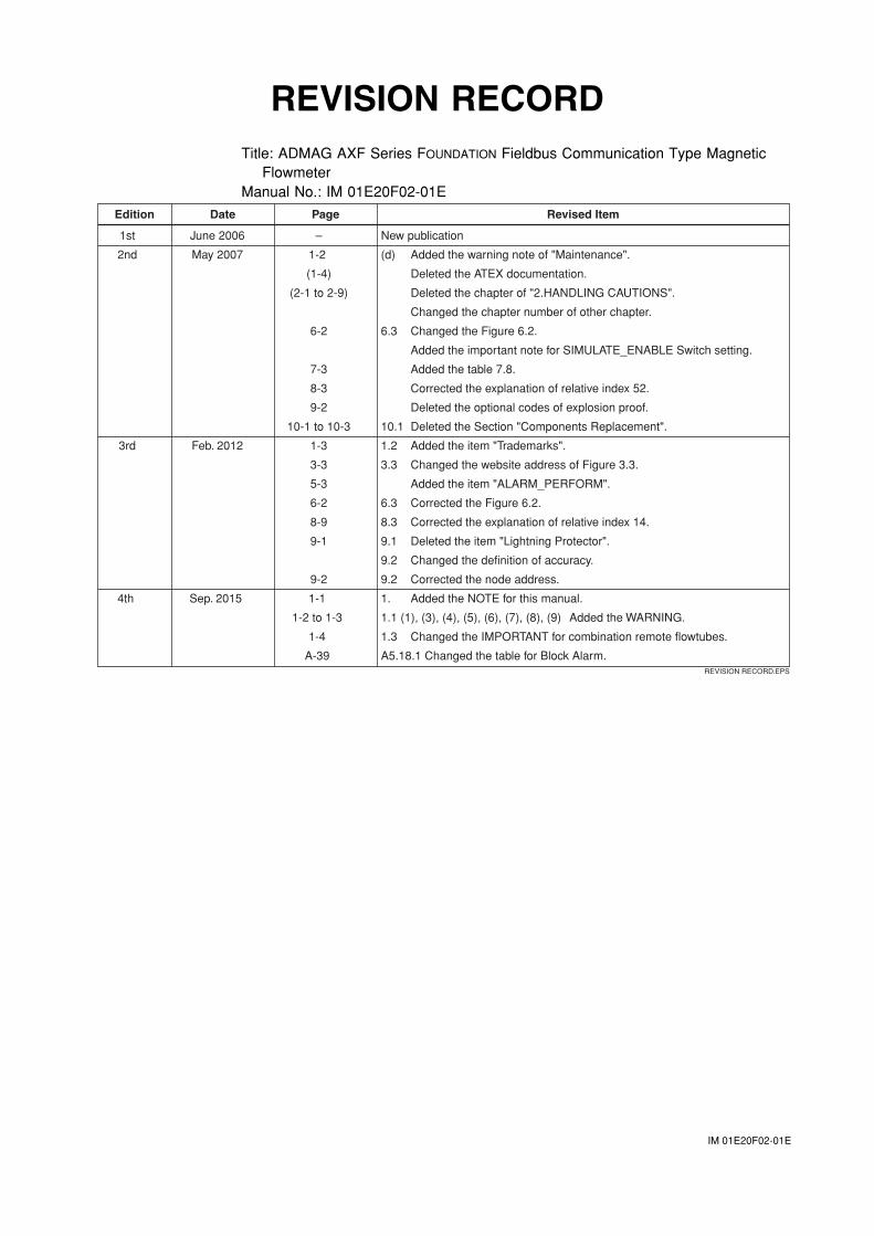
IM 01E20F02-01E
REVISION RECORDTitle: ADMAG AXF Series FOUNDATION Fieldbus Communication Type Magnetic
FlowmeterManual No.: IM 01E20F02-01E
REVISION RECORD.EPS
Edition Date Page Revised Item
1st June 2006 – New publication
2nd May 2007 1-2 (d) Added the warning note of "Maintenance".
(1-4) Deleted the ATEX documentation.
(2-1 to 2-9) Deleted the chapter of "2.HANDLING CAUTIONS".
Changed the chapter number of other chapter.
6-2 6.3 Changed the Figure 6.2.
Added the important note for SIMULATE_ENABLE Switch setting.
7-3 Added the table 7.8.
8-3 Corrected the explanation of relative index 52.
9-2 Deleted the optional codes of explosion proof.
10-1 to 10-3 10.1 Deleted the Section "Components Replacement".
3rd Feb. 2012 1-3 1.2 Added the item "Trademarks".
3-3 3.3 Changed the website address of Figure 3.3.
5-3 Added the item "ALARM_PERFORM".
6-2 6.3 Corrected the Figure 6.2.
8-9 8.3 Corrected the explanation of relative index 14.
9-1 9.1 Deleted the item "Lightning Protector".
9.2 Changed the definition of accuracy.
9-2 9.2 Corrected the node address.
4th Sep. 2015 1-1 1. Added the NOTE for this manual.
1-2 to 1-3 1.1 (1), (3), (4), (5), (6), (7), (8), (9) Added the WARNING.
1-4 1.3 Changed the IMPORTANT for combination remote flowtubes.
A-39 A5.18.1 Changed the table for Block Alarm.


![User’s AXFA14G/C Manual Magnetic Flowmeter Remote ...web-material3.yokogawa.com/IM01E20C02-01E.pdf · AXFA14G/C Magnetic Flowmeter Remote Converter [Hardware Edition/Software Edition]](https://img.pdfslide.us/doc/110x75/5e9c291191173b06060e3012/useras-axfa14gc-manual-magnetic-flowmeter-remote-web-axfa14gc-magnetic-flowmeter.jpg)