Embed Size (px)
Citation preview

User ManualUser ManualUser ManualUser ManualUser ManualUser ManualUser ManualUser ManualUser ManualUser ManualUser ManualUser ManualUser ManualUser ManualUser ManualUser ManualUser ManualUser ManualUser ManualUser ManualUser ManualUser ManualUser ManualUser ManualUser ManualUser ManualUser ManualUser ManualUser ManualUser ManualUser ManualUser ManualUser ManualNetCom PlusNetCom PlusNetCom PlusNetCom PlusNetCom PlusNetCom PlusNetCom PlusNetCom PlusNetCom PlusNetCom PlusNetCom PlusNetCom PlusNetCom PlusNetCom PlusNetCom PlusNetCom PlusNetCom PlusNetCom PlusNetCom PlusNetCom PlusNetCom PlusNetCom PlusNetCom PlusNetCom PlusNetCom PlusNetCom PlusNetCom PlusNetCom PlusNetCom PlusNetCom PlusNetCom PlusNetCom PlusNetCom Plus
Edition: September 2016Edition: September 2016Edition: September 2016Edition: September 2016Edition: September 2016Edition: September 2016Edition: September 2016Edition: September 2016Edition: September 2016Edition: September 2016Edition: September 2016Edition: September 2016Edition: September 2016Edition: September 2016Edition: September 2016Edition: September 2016Edition: September 2016
Tel: +49 40 528 401 0Fax: +49 40 528 401 99Web: www.visionsystems.deSupport: [email protected]
The software described in this manual is furnished under a license agreement and may be usedonly in accordance with the terms of that agreement.
Copyright Notice
Copyright © 2009-2016 Vision Systems. All rights reserved. Reproduction without permission isprohibited.
Trademarks
VScom is a registered trademark of Vision Systems GmbH. All other trademarks and brands areproperty of their rightful owners.
Disclaimer
Vision Systems reserves the right to make changes and improvements to its product without pro-viding notice.
Vision Systems provides this document “as is”, without warranty of any kind, either expressed orimplied, including, but not limited to, its particular purpose. Vision Systems reserves the rightto make improvements and/or changes to this manual, or to the products and/or the programsdescribed in this manual, at any time.
Information provided in this manual is intended to be accurate and reliable. However, VisionSystems assumes no responsibility for its use, or for any infringements on the rights of third partiesthat may result from its use.
This product might include unintentional technical or typographical errors. Changes are period-ically made to the information herein to correct such errors, and these changes are incorporatedinto new editions of the publication.
September 2016 NetCom Plus User Manual 2
Contents
Contents
1 Overview 11
2 Introduction 112.1 About this Manual . . . . . . . . . . . . . . . . . . . . . . . . . . . . . . . . . . . . . 112.2 Features . . . . . . . . . . . . . . . . . . . . . . . . . . . . . . . . . . . . . . . . . . . 122.3 Product Specifications . . . . . . . . . . . . . . . . . . . . . . . . . . . . . . . . . . . 12
2.3.1 Common characteristics . . . . . . . . . . . . . . . . . . . . . . . . . . . . . . 132.3.2 Device specific Characteristics . . . . . . . . . . . . . . . . . . . . . . . . . . 13
2.3.2.1 NetCom Plus 111 . . . . . . . . . . . . . . . . . . . . . . . . . . . . 132.3.2.2 NetCom Plus 113 . . . . . . . . . . . . . . . . . . . . . . . . . . . . 142.3.2.3 NetCom Plus 211 . . . . . . . . . . . . . . . . . . . . . . . . . . . . 152.3.2.4 NetCom Plus 213 . . . . . . . . . . . . . . . . . . . . . . . . . . . . 152.3.2.5 NetCom Plus 411 . . . . . . . . . . . . . . . . . . . . . . . . . . . . 162.3.2.6 NetCom Plus 411 POE . . . . . . . . . . . . . . . . . . . . . . . . . 162.3.2.7 NetCom Plus 413 . . . . . . . . . . . . . . . . . . . . . . . . . . . . 162.3.2.8 NetCom Plus 413 POE . . . . . . . . . . . . . . . . . . . . . . . . . 172.3.2.9 NetCom Plus 811 . . . . . . . . . . . . . . . . . . . . . . . . . . . . 182.3.2.10 NetCom Plus 811 POE . . . . . . . . . . . . . . . . . . . . . . . . . 182.3.2.11 NetCom Plus 813 . . . . . . . . . . . . . . . . . . . . . . . . . . . . 192.3.2.12 NetCom Plus 813 POE . . . . . . . . . . . . . . . . . . . . . . . . . 192.3.2.13 NetCom Plus 811 DIO . . . . . . . . . . . . . . . . . . . . . . . . . 20
2.4 Packing List . . . . . . . . . . . . . . . . . . . . . . . . . . . . . . . . . . . . . . . . . 21
3 Hardware Description 223.1 Serial Port Configuration . . . . . . . . . . . . . . . . . . . . . . . . . . . . . . . . . 223.2 Serial Signal Assignment . . . . . . . . . . . . . . . . . . . . . . . . . . . . . . . . . . 233.3 RS422/485 Electrical Configuration . . . . . . . . . . . . . . . . . . . . . . . . . . . 24
3.3.1 Termination Resistors . . . . . . . . . . . . . . . . . . . . . . . . . . . . . . . 243.3.2 BIAS Function . . . . . . . . . . . . . . . . . . . . . . . . . . . . . . . . . . . 24
3.4 Serial Port Simple Settings . . . . . . . . . . . . . . . . . . . . . . . . . . . . . . . . 243.5 Digital Input/Output . . . . . . . . . . . . . . . . . . . . . . . . . . . . . . . . . . . 25
3.5.1 Input Connection . . . . . . . . . . . . . . . . . . . . . . . . . . . . . . . . . . 253.5.2 Output Connection . . . . . . . . . . . . . . . . . . . . . . . . . . . . . . . . . 25
3.6 Network . . . . . . . . . . . . . . . . . . . . . . . . . . . . . . . . . . . . . . . . . . . 253.6.1 Ethernet and LED . . . . . . . . . . . . . . . . . . . . . . . . . . . . . . . . . 253.6.2 WLAN Configuration . . . . . . . . . . . . . . . . . . . . . . . . . . . . . . . 263.6.3 WLAN Antenna . . . . . . . . . . . . . . . . . . . . . . . . . . . . . . . . . . 263.6.4 WLAN LED . . . . . . . . . . . . . . . . . . . . . . . . . . . . . . . . . . . . 26
3.7 Power Supply . . . . . . . . . . . . . . . . . . . . . . . . . . . . . . . . . . . . . . . . 273.7.1 Terminal Block Power . . . . . . . . . . . . . . . . . . . . . . . . . . . . . . . 27
4 Windows Virtual COM Driver 284.1 Installation Procedure . . . . . . . . . . . . . . . . . . . . . . . . . . . . . . . . . . . 28
4.1.1 Start the Installation Wizard . . . . . . . . . . . . . . . . . . . . . . . . . . . 284.1.1.1 User Account Control (UAC) . . . . . . . . . . . . . . . . . . . . . . 294.1.1.2 Methods of Installation . . . . . . . . . . . . . . . . . . . . . . . . . 294.1.1.3 Proceed Installation . . . . . . . . . . . . . . . . . . . . . . . . . . . 30
September 2016 NetCom Plus User Manual 3
Contents
4.1.1.4 Request for Trust . . . . . . . . . . . . . . . . . . . . . . . . . . . . 314.1.2 Find and Configure NetCom+ Devices . . . . . . . . . . . . . . . . . . . . . . 32
4.1.2.1 Configure IP Parameters . . . . . . . . . . . . . . . . . . . . . . . . 334.1.2.2 Configure Firewall . . . . . . . . . . . . . . . . . . . . . . . . . . . . 35
4.1.3 Install Drivers . . . . . . . . . . . . . . . . . . . . . . . . . . . . . . . . . . . 354.2 Verify the Installation . . . . . . . . . . . . . . . . . . . . . . . . . . . . . . . . . . . 364.3 Update the Drivers and Tools . . . . . . . . . . . . . . . . . . . . . . . . . . . . . . . 374.4 Configuration of the Virtual COM Driver . . . . . . . . . . . . . . . . . . . . . . . . 38
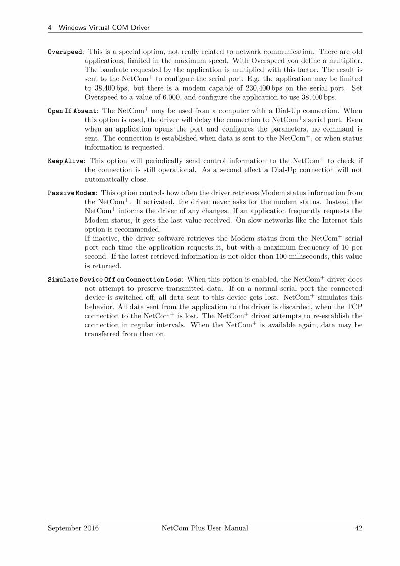
4.4.1 Configure the Serial Ports . . . . . . . . . . . . . . . . . . . . . . . . . . . . . 384.4.2 Performance Issues . . . . . . . . . . . . . . . . . . . . . . . . . . . . . . . . . 394.4.3 Network & Misc Properties . . . . . . . . . . . . . . . . . . . . . . . . . . . . 414.4.4 Remote Settings Properties . . . . . . . . . . . . . . . . . . . . . . . . . . . . 434.4.5 Installation of NetCom Plus Servers . . . . . . . . . . . . . . . . . . . . . . . 45
4.4.5.1 Changing the Installation . . . . . . . . . . . . . . . . . . . . . . . . 474.5 Uninstall the Drivers and Tools . . . . . . . . . . . . . . . . . . . . . . . . . . . . . . 48
5 Configure with NetCom Manager 505.1 Starting NetCom Manager . . . . . . . . . . . . . . . . . . . . . . . . . . . . . . . . . 515.2 NetCom Server Settings – Info . . . . . . . . . . . . . . . . . . . . . . . . . . . . . . 525.3 NetCom Server Settings – Ports . . . . . . . . . . . . . . . . . . . . . . . . . . . . . . 535.4 NetCom Server Settings – Firewall . . . . . . . . . . . . . . . . . . . . . . . . . . . . 545.5 Manual Detection/Installation of a NetCom . . . . . . . . . . . . . . . . . . . . . . . 555.6 Firewall Traversal Configuration . . . . . . . . . . . . . . . . . . . . . . . . . . . . . 55
5.6.1 SOHO Firewall example . . . . . . . . . . . . . . . . . . . . . . . . . . . . . . 555.6.2 SOHO Virtual Servers . . . . . . . . . . . . . . . . . . . . . . . . . . . . . . . 565.6.3 NetCom Detection through SOHO Firewall . . . . . . . . . . . . . . . . . . . 565.6.4 Serial Ports through SOHO Firewall . . . . . . . . . . . . . . . . . . . . . . . 575.6.5 DMZ and Virtual Servers . . . . . . . . . . . . . . . . . . . . . . . . . . . . . 585.6.6 Firewalls in Foreign Networks . . . . . . . . . . . . . . . . . . . . . . . . . . . 58
5.7 Dynamic IP Address and OpenVPN™ . . . . . . . . . . . . . . . . . . . . . . . . . . 58
6 Configure the Operation Modes 596.1 Accessing the Configurations . . . . . . . . . . . . . . . . . . . . . . . . . . . . . . . 59
6.1.1 Web Browser Configuration . . . . . . . . . . . . . . . . . . . . . . . . . . . . 596.1.2 Telnet Configuration . . . . . . . . . . . . . . . . . . . . . . . . . . . . . . . . 606.1.3 Serial Configuration . . . . . . . . . . . . . . . . . . . . . . . . . . . . . . . . 62
6.2 NetCom Configuration Options . . . . . . . . . . . . . . . . . . . . . . . . . . . . . . 626.2.1 Server Configuration . . . . . . . . . . . . . . . . . . . . . . . . . . . . . . . . 62
6.2.1.1 Server Info . . . . . . . . . . . . . . . . . . . . . . . . . . . . . . . . 636.2.1.2 Server Parameter . . . . . . . . . . . . . . . . . . . . . . . . . . . . 636.2.1.3 Wireless Parameter . . . . . . . . . . . . . . . . . . . . . . . . . . . 666.2.1.4 Encrypted Communication . . . . . . . . . . . . . . . . . . . . . . . 676.2.1.5 viaVPN Remote Management and Access . . . . . . . . . . . . . . . 686.2.1.6 Modbus GPIO . . . . . . . . . . . . . . . . . . . . . . . . . . . . . . 706.2.1.7 Authentication . . . . . . . . . . . . . . . . . . . . . . . . . . . . . . 716.2.1.8 Date & Time . . . . . . . . . . . . . . . . . . . . . . . . . . . . . . . 716.2.1.9 Save . . . . . . . . . . . . . . . . . . . . . . . . . . . . . . . . . . . . 72
6.2.2 Serial Port Configuration . . . . . . . . . . . . . . . . . . . . . . . . . . . . . 736.2.2.1 Serial Settings . . . . . . . . . . . . . . . . . . . . . . . . . . . . . . 746.2.2.2 Transfer Settings . . . . . . . . . . . . . . . . . . . . . . . . . . . . . 76
September 2016 NetCom Plus User Manual 4
Contents
6.2.2.2.1 Driver Mode . . . . . . . . . . . . . . . . . . . . . . . . . . 776.2.2.2.2 TCP Raw Server . . . . . . . . . . . . . . . . . . . . . . . . 786.2.2.2.3 TCP Raw Client . . . . . . . . . . . . . . . . . . . . . . . . 796.2.2.2.4 Null Modem Tunnel . . . . . . . . . . . . . . . . . . . . . . 806.2.2.2.5 TCP Advanced Settings . . . . . . . . . . . . . . . . . . . . 826.2.2.2.6 UDP Data Transfer . . . . . . . . . . . . . . . . . . . . . . 836.2.2.2.7 IP-Modem . . . . . . . . . . . . . . . . . . . . . . . . . . . 846.2.2.2.8 Print Server Function . . . . . . . . . . . . . . . . . . . . . 85
6.2.2.3 Save . . . . . . . . . . . . . . . . . . . . . . . . . . . . . . . . . . . . 856.2.3 NetCom Tools . . . . . . . . . . . . . . . . . . . . . . . . . . . . . . . . . . . 85
6.2.3.1 Ping . . . . . . . . . . . . . . . . . . . . . . . . . . . . . . . . . . . . 866.2.3.2 Statistics . . . . . . . . . . . . . . . . . . . . . . . . . . . . . . . . . 876.2.3.3 Netstat . . . . . . . . . . . . . . . . . . . . . . . . . . . . . . . . . . 886.2.3.4 Wireless . . . . . . . . . . . . . . . . . . . . . . . . . . . . . . . . . . 896.2.3.5 Firmware . . . . . . . . . . . . . . . . . . . . . . . . . . . . . . . . . 906.2.3.6 Save and Load Configuration . . . . . . . . . . . . . . . . . . . . . . 916.2.3.7 Logging and Debug . . . . . . . . . . . . . . . . . . . . . . . . . . . 916.2.3.8 Save . . . . . . . . . . . . . . . . . . . . . . . . . . . . . . . . . . . . 92
6.2.4 Reboot . . . . . . . . . . . . . . . . . . . . . . . . . . . . . . . . . . . . . . . 926.2.5 Save&Exit Menu . . . . . . . . . . . . . . . . . . . . . . . . . . . . . . . . . . 92
6.2.5.1 Save Parameter . . . . . . . . . . . . . . . . . . . . . . . . . . . . . 926.2.5.2 Exit . . . . . . . . . . . . . . . . . . . . . . . . . . . . . . . . . . . . 936.2.5.3 Reboot . . . . . . . . . . . . . . . . . . . . . . . . . . . . . . . . . . 93
6.3 Erase Configuration of NetCom . . . . . . . . . . . . . . . . . . . . . . . . . . . . . . 93
7 Operation in Linux 947.1 Via Fixed TTY Pseudo Serial Port (socat) . . . . . . . . . . . . . . . . . . . . . . . . 947.2 Via TCP Raw Server Mode . . . . . . . . . . . . . . . . . . . . . . . . . . . . . . . . 95
8 IP Modem Function 968.1 Some possible Scenarios . . . . . . . . . . . . . . . . . . . . . . . . . . . . . . . . . . 968.2 Serial Signals and Cables . . . . . . . . . . . . . . . . . . . . . . . . . . . . . . . . . 968.3 Operation Modes by IP Modem . . . . . . . . . . . . . . . . . . . . . . . . . . . . . . 978.4 Hayes Commands . . . . . . . . . . . . . . . . . . . . . . . . . . . . . . . . . . . . . . 97
8.4.1 AT command set . . . . . . . . . . . . . . . . . . . . . . . . . . . . . . . . . . 988.4.1.1 Standard AT-Commands . . . . . . . . . . . . . . . . . . . . . . . . 988.4.1.2 Extended AT-Commands . . . . . . . . . . . . . . . . . . . . . . . . 988.4.1.3 Non-AT commands . . . . . . . . . . . . . . . . . . . . . . . . . . . 99
8.4.2 S-Registers for Configuration . . . . . . . . . . . . . . . . . . . . . . . . . . . 998.4.3 Sample Commands used by Windows . . . . . . . . . . . . . . . . . . . . . . 99
8.5 Description of AT–Commands . . . . . . . . . . . . . . . . . . . . . . . . . . . . . . . 998.5.1 AT D (dial) . . . . . . . . . . . . . . . . . . . . . . . . . . . . . . . . . . . . . 1008.5.2 AT O (online / data mode) . . . . . . . . . . . . . . . . . . . . . . . . . . . . 1008.5.3 AT A (answer call) . . . . . . . . . . . . . . . . . . . . . . . . . . . . . . . . . 1008.5.4 AT B (modulation) [ATB1] . . . . . . . . . . . . . . . . . . . . . . . . . . . . 1008.5.5 AT E (echo) [ATE1] . . . . . . . . . . . . . . . . . . . . . . . . . . . . . . . . 1018.5.6 AT Q (quiet) [ATQ0] . . . . . . . . . . . . . . . . . . . . . . . . . . . . . . . 1018.5.7 AT V (verbose) [ATV1] . . . . . . . . . . . . . . . . . . . . . . . . . . . . . . 1018.5.8 AT H (hangup) [ATH0] . . . . . . . . . . . . . . . . . . . . . . . . . . . . . . 1018.5.9 AT I(n) (information) [ATI0] . . . . . . . . . . . . . . . . . . . . . . . . . . . 101
September 2016 NetCom Plus User Manual 5
Contents
8.5.10 AT S (setup) . . . . . . . . . . . . . . . . . . . . . . . . . . . . . . . . . . . . 1028.5.11 AT L (loudness) . . . . . . . . . . . . . . . . . . . . . . . . . . . . . . . . . . 1028.5.12 AT M (speaker) . . . . . . . . . . . . . . . . . . . . . . . . . . . . . . . . . . 1028.5.13 AT N (auto baud) [ATN0] . . . . . . . . . . . . . . . . . . . . . . . . . . . . . 1028.5.14 AT Z (reset) . . . . . . . . . . . . . . . . . . . . . . . . . . . . . . . . . . . . 1028.5.15 AT &F (factory settings) [AT&F0] . . . . . . . . . . . . . . . . . . . . . . . . 1038.5.16 AT &C (DCD configuration) [AT&C1] . . . . . . . . . . . . . . . . . . . . . . 1038.5.17 AT &S (DSR configuration) [AT&S0] . . . . . . . . . . . . . . . . . . . . . . 1038.5.18 AT &D (DTR configuration) [AT&D2] . . . . . . . . . . . . . . . . . . . . . . 1038.5.19 AT &K (handshake) [AT&K3] . . . . . . . . . . . . . . . . . . . . . . . . . . 1048.5.20 AT \Q [AT\Q3] . . . . . . . . . . . . . . . . . . . . . . . . . . . . . . . . . . 1048.5.21 AT &V (view profile) . . . . . . . . . . . . . . . . . . . . . . . . . . . . . . . 1048.5.22 AT &W (save profile) . . . . . . . . . . . . . . . . . . . . . . . . . . . . . . . 1048.5.23 AT &Z (save destination) . . . . . . . . . . . . . . . . . . . . . . . . . . . . . 104
9 Print Server Operation 1059.1 Printer Queue . . . . . . . . . . . . . . . . . . . . . . . . . . . . . . . . . . . . . . . . 1059.2 Printer Reset . . . . . . . . . . . . . . . . . . . . . . . . . . . . . . . . . . . . . . . . 105
9.2.1 Init String Definition . . . . . . . . . . . . . . . . . . . . . . . . . . . . . . . . 1059.2.1.1 ASCII Text . . . . . . . . . . . . . . . . . . . . . . . . . . . . . . . . 1069.2.1.2 ASCII Control Codes . . . . . . . . . . . . . . . . . . . . . . . . . . 1069.2.1.3 Numeric Codes . . . . . . . . . . . . . . . . . . . . . . . . . . . . . . 1069.2.1.4 Modem Control Signals . . . . . . . . . . . . . . . . . . . . . . . . . 1069.2.1.5 Timing Options . . . . . . . . . . . . . . . . . . . . . . . . . . . . . 106
9.2.2 Reset Example . . . . . . . . . . . . . . . . . . . . . . . . . . . . . . . . . . . 1069.3 Operation in Windows® . . . . . . . . . . . . . . . . . . . . . . . . . . . . . . . . . . 107
9.3.1 Add a New Printer . . . . . . . . . . . . . . . . . . . . . . . . . . . . . . . . . 1079.3.1.1 Create new printer port . . . . . . . . . . . . . . . . . . . . . . . . . 1079.3.1.2 Name the new Printer Port . . . . . . . . . . . . . . . . . . . . . . . 1089.3.1.3 Configure the Printer Port . . . . . . . . . . . . . . . . . . . . . . . 1099.3.1.4 Install Printer Driver . . . . . . . . . . . . . . . . . . . . . . . . . . 109
9.3.2 Modify an Existing Printer . . . . . . . . . . . . . . . . . . . . . . . . . . . . 1099.3.2.1 Open the properties . . . . . . . . . . . . . . . . . . . . . . . . . . . 1099.3.2.2 Add the Print Server Port . . . . . . . . . . . . . . . . . . . . . . . 110
10 OpenVPN™ Encryption 11110.1 OpenVPN™ Installation . . . . . . . . . . . . . . . . . . . . . . . . . . . . . . . . . . 11110.2 NetCom OpenVPN Configuration . . . . . . . . . . . . . . . . . . . . . . . . . . . . . 11210.3 OpenVPN™ Configuration . . . . . . . . . . . . . . . . . . . . . . . . . . . . . . . . 113
10.3.1 Create OpenVPN™ Configuration . . . . . . . . . . . . . . . . . . . . . . . . 11310.3.2 Create OpenVPN™ Certificate and Keys . . . . . . . . . . . . . . . . . . . . 11410.3.3 Start NetCom Plus with OpenVPN™ active . . . . . . . . . . . . . . . . . . . 11510.3.4 Start OpenVPN™ by Context-Menu . . . . . . . . . . . . . . . . . . . . . . . 11510.3.5 Start OpenVPN™ by Command line . . . . . . . . . . . . . . . . . . . . . . . 11610.3.6 Start OpenVPN™ as Windows Service . . . . . . . . . . . . . . . . . . . . . . 117
10.4 OpenVPN™ without Encryption . . . . . . . . . . . . . . . . . . . . . . . . . . . . . 11810.5 Reconfigure Virtual Serial Ports for OpenVPN™ . . . . . . . . . . . . . . . . . . . . 119
11 viaVPN Remote Access System 12011.1 Obstacles when used via Internet . . . . . . . . . . . . . . . . . . . . . . . . . . . . . 120
September 2016 NetCom Plus User Manual 6
List of Figures
11.2 How viaVPN solves the above Issues . . . . . . . . . . . . . . . . . . . . . . . . . . . 12011.3 Configuration of viaVPN Parameters . . . . . . . . . . . . . . . . . . . . . . . . . . . 12111.4 Operation with viaVPN System . . . . . . . . . . . . . . . . . . . . . . . . . . . . . . 121
12 Modbus/TCP for Digital-Input/Output 12312.1 Specifications . . . . . . . . . . . . . . . . . . . . . . . . . . . . . . . . . . . . . . . . 12312.2 Examples . . . . . . . . . . . . . . . . . . . . . . . . . . . . . . . . . . . . . . . . . . 124
12.2.1 Read two input signals . . . . . . . . . . . . . . . . . . . . . . . . . . . . . . . 12412.2.2 Write one output signal . . . . . . . . . . . . . . . . . . . . . . . . . . . . . . 124
13 TCP/IP Description 12513.1 Recommended Settings . . . . . . . . . . . . . . . . . . . . . . . . . . . . . . . . . . . 125
13.1.1 Static Configuration . . . . . . . . . . . . . . . . . . . . . . . . . . . . . . . . 12513.1.2 DHCP Configuration . . . . . . . . . . . . . . . . . . . . . . . . . . . . . . . . 12513.1.3 Automatic Configuration (APIPA) . . . . . . . . . . . . . . . . . . . . . . . . 12613.1.4 Other Configuration . . . . . . . . . . . . . . . . . . . . . . . . . . . . . . . . 126
14 Troubleshooting Guide 127
15 Glossary of Terms 129
16 History 131
List of Figures1 NetCom Plus 111 / 113 . . . . . . . . . . . . . . . . . . . . . . . . . . . . . . . . . . 142 NetCom Plus 213 Top, Front, Left and Back Side . . . . . . . . . . . . . . . . . . . . 153 NetCom Plus 411 / 413 Front side . . . . . . . . . . . . . . . . . . . . . . . . . . . . 174 NetCom Plus 411 / 413 / 413 POE Rear side . . . . . . . . . . . . . . . . . . . . . . 175 NetCom Plus 411 POE Rear side . . . . . . . . . . . . . . . . . . . . . . . . . . . . . 186 NetCom Plus 811 / 813 Front side . . . . . . . . . . . . . . . . . . . . . . . . . . . . 197 NetCom Plus 811 / 813 / 813 POE Rear side . . . . . . . . . . . . . . . . . . . . . . 208 NetCom Plus 811 POE Rear side . . . . . . . . . . . . . . . . . . . . . . . . . . . . . 209 NetCom Plus 811 DIO . . . . . . . . . . . . . . . . . . . . . . . . . . . . . . . . . . . 2110 Connector
DSub-9 male . . . . . . . . . . . . . . . . . . . . . . . . . . . . . . . . . . . . . . . . 2311 DIP NetCom Plus . . . . . . . . . . . . . . . . . . . . . . . . . . . . . . . . . . . . . 2412 Terminal Block Input . . . . . . . . . . . . . . . . . . . . . . . . . . . . . . . . . . . 2513 Terminal Block Output . . . . . . . . . . . . . . . . . . . . . . . . . . . . . . . . . . 2514 Power Terminal Block . . . . . . . . . . . . . . . . . . . . . . . . . . . . . . . . . . . 2715 Installation Wizard . . . . . . . . . . . . . . . . . . . . . . . . . . . . . . . . . . . . . 2816 User Account Control . . . . . . . . . . . . . . . . . . . . . . . . . . . . . . . . . . . 2917 NetCom+ Driver Installation . . . . . . . . . . . . . . . . . . . . . . . . . . . . . . . 2918 Start Driver Installation . . . . . . . . . . . . . . . . . . . . . . . . . . . . . . . . . . 3019 Copy Driver Files . . . . . . . . . . . . . . . . . . . . . . . . . . . . . . . . . . . . . . 3120 Install Request . . . . . . . . . . . . . . . . . . . . . . . . . . . . . . . . . . . . . . . 3121 Firewall options . . . . . . . . . . . . . . . . . . . . . . . . . . . . . . . . . . . . . . . 3222 Discover and Select NetCom+ Devices for Installation . . . . . . . . . . . . . . . . . 3323 NetCom+ in Manager . . . . . . . . . . . . . . . . . . . . . . . . . . . . . . . . . . . 33
September 2016 NetCom Plus User Manual 7

List of Figures
24 Define NetCom+s IP Configuration . . . . . . . . . . . . . . . . . . . . . . . . . . . . 3425 DNS Name for NetCom+ Server . . . . . . . . . . . . . . . . . . . . . . . . . . . . . 3426 Sending Parameters to a NetCom+ . . . . . . . . . . . . . . . . . . . . . . . . . . . . 3527 Virtual Com Ports installing in Windows 7 . . . . . . . . . . . . . . . . . . . . . . . 3528 Virtual Com Ports installing in Windows 10 . . . . . . . . . . . . . . . . . . . . . . . 3629 VScom drivers in the Start Menu . . . . . . . . . . . . . . . . . . . . . . . . . . . . . 3630 NetCom+ in Device Manager . . . . . . . . . . . . . . . . . . . . . . . . . . . . . . . 3731 NetCom+ COM Port Serial Settings . . . . . . . . . . . . . . . . . . . . . . . . . . . 3832 NetCom+ COM Port Performance Settings . . . . . . . . . . . . . . . . . . . . . . . 3933 NetCom+ COM Port Network/Misc Properties . . . . . . . . . . . . . . . . . . . . . 4134 NetCom+ COM Port Remote Settings Properties . . . . . . . . . . . . . . . . . . . . 4335 Select NetCom+ to install . . . . . . . . . . . . . . . . . . . . . . . . . . . . . . . . . 4536 New NetCom+ . . . . . . . . . . . . . . . . . . . . . . . . . . . . . . . . . . . . . . . 4537 Installed NetCom+ . . . . . . . . . . . . . . . . . . . . . . . . . . . . . . . . . . . . . 4538 “Bad” NetCom+ . . . . . . . . . . . . . . . . . . . . . . . . . . . . . . . . . . . . . . 4639 Excluded NetCom+ . . . . . . . . . . . . . . . . . . . . . . . . . . . . . . . . . . . . 4640 Disconnected NetCom+ . . . . . . . . . . . . . . . . . . . . . . . . . . . . . . . . . . 4641 NetCom Plus Manager Ports View . . . . . . . . . . . . . . . . . . . . . . . . . . . . 4742 Reconfigured NetCom+ found . . . . . . . . . . . . . . . . . . . . . . . . . . . . . . . 4743 Replaced NetCom+ found . . . . . . . . . . . . . . . . . . . . . . . . . . . . . . . . . 4844 Uninstall NetCom+ Drivers via Settings App . . . . . . . . . . . . . . . . . . . . . . 4845 Uninstall NetCom+ Drivers in Windows 7 . . . . . . . . . . . . . . . . . . . . . . . . 4946 Uninstall NetCom+ Drivers in Windows 7 Start Menu . . . . . . . . . . . . . . . . . 4947 Remove, Repair . . . . . . . . . . . . . . . . . . . . . . . . . . . . . . . . . . . . . . . 4948 NetCom Plus Manager . . . . . . . . . . . . . . . . . . . . . . . . . . . . . . . . . . . 5049 NetCom Manager in Start Menu . . . . . . . . . . . . . . . . . . . . . . . . . . . . . 5050 NetCom Manager Servers Panel . . . . . . . . . . . . . . . . . . . . . . . . . . . . . 5151 NetCom Manager Server Settings - Info . . . . . . . . . . . . . . . . . . . . . . . . . 5252 NetCom Manager Server Settings - Ports . . . . . . . . . . . . . . . . . . . . . . . . 5353 NetCom Manager Server Settings - Firewall . . . . . . . . . . . . . . . . . . . . . . . 5454 NetCom Manager Port Configuration for Driver . . . . . . . . . . . . . . . . . . . . . 5755 Configuration Menu in Web Browser . . . . . . . . . . . . . . . . . . . . . . . . . . . 6056 Request to Reboot in Web Browser . . . . . . . . . . . . . . . . . . . . . . . . . . . . 6057 Password Request in Telnet . . . . . . . . . . . . . . . . . . . . . . . . . . . . . . . . 6158 Select Terminal Type in Telnet . . . . . . . . . . . . . . . . . . . . . . . . . . . . . . 6159 Main Menu of Configuration Console in Telnet . . . . . . . . . . . . . . . . . . . . . 6160 Server Information . . . . . . . . . . . . . . . . . . . . . . . . . . . . . . . . . . . . . 6361 Server Parameter Web Interface . . . . . . . . . . . . . . . . . . . . . . . . . . . . . . 6462 Server Parameter Telnet Interface . . . . . . . . . . . . . . . . . . . . . . . . . . . . . 6463 Wireless Parameter . . . . . . . . . . . . . . . . . . . . . . . . . . . . . . . . . . . . . 6664 Wireless Encryption Modes . . . . . . . . . . . . . . . . . . . . . . . . . . . . . . . . 6765 OpenVPN Network Parameter . . . . . . . . . . . . . . . . . . . . . . . . . . . . . . 6866 viaVPN Network Parameter . . . . . . . . . . . . . . . . . . . . . . . . . . . . . . . . 6967 Modbus/TCP Network Parameter . . . . . . . . . . . . . . . . . . . . . . . . . . . . 7068 Access Authentification . . . . . . . . . . . . . . . . . . . . . . . . . . . . . . . . . . 7169 Date & Time Retrieval Options . . . . . . . . . . . . . . . . . . . . . . . . . . . . . . 7270 Port Page Selection in Web Browser . . . . . . . . . . . . . . . . . . . . . . . . . . . 7371 Port Selection in Telnet . . . . . . . . . . . . . . . . . . . . . . . . . . . . . . . . . . 7372 Serial Settings . . . . . . . . . . . . . . . . . . . . . . . . . . . . . . . . . . . . . . . . 74
September 2016 NetCom Plus User Manual 8
List of Figures
73 Operation Mode by Software . . . . . . . . . . . . . . . . . . . . . . . . . . . . . . . 7574 Advanced Flow Control . . . . . . . . . . . . . . . . . . . . . . . . . . . . . . . . . . 7575 Serial Port Mode Selection . . . . . . . . . . . . . . . . . . . . . . . . . . . . . . . . . 7676 Driver Mode parameters . . . . . . . . . . . . . . . . . . . . . . . . . . . . . . . . . . 7777 TCP Raw Server parameters . . . . . . . . . . . . . . . . . . . . . . . . . . . . . . . 7878 TCP Raw Client parameters . . . . . . . . . . . . . . . . . . . . . . . . . . . . . . . 7979 Null Modem Tunnel . . . . . . . . . . . . . . . . . . . . . . . . . . . . . . . . . . . . 8080 TCP Advanced Settings . . . . . . . . . . . . . . . . . . . . . . . . . . . . . . . . . . 8281 UDP Data Transfer . . . . . . . . . . . . . . . . . . . . . . . . . . . . . . . . . . . . . 8382 IP-Modem . . . . . . . . . . . . . . . . . . . . . . . . . . . . . . . . . . . . . . . . . . 8483 Print Server Configuration . . . . . . . . . . . . . . . . . . . . . . . . . . . . . . . . . 8584 Ping and Response in Web Browser . . . . . . . . . . . . . . . . . . . . . . . . . . . 8685 Ping and Response in Telnet . . . . . . . . . . . . . . . . . . . . . . . . . . . . . . . 8686 Statistics Port Selection . . . . . . . . . . . . . . . . . . . . . . . . . . . . . . . . . . 8787 Port Statistics . . . . . . . . . . . . . . . . . . . . . . . . . . . . . . . . . . . . . . . . 8788 Start Netstat . . . . . . . . . . . . . . . . . . . . . . . . . . . . . . . . . . . . . . . . 8889 Netstat Sample Output . . . . . . . . . . . . . . . . . . . . . . . . . . . . . . . . . . 8890 WLAN Scan . . . . . . . . . . . . . . . . . . . . . . . . . . . . . . . . . . . . . . . . 8991 WLAN Scan Output . . . . . . . . . . . . . . . . . . . . . . . . . . . . . . . . . . . . 8992 Firmware Upload . . . . . . . . . . . . . . . . . . . . . . . . . . . . . . . . . . . . . . 9093 Save and Load Configuration in Web Browser . . . . . . . . . . . . . . . . . . . . . . 9194 Syslog & Debuglog Parameters . . . . . . . . . . . . . . . . . . . . . . . . . . . . . . 9195 Menu Save modified Parameters in Telnet . . . . . . . . . . . . . . . . . . . . . . . . 9296 Menu Exit from Configuration in Telnet . . . . . . . . . . . . . . . . . . . . . . . . . 9397 Exit and Reboot in Telnet . . . . . . . . . . . . . . . . . . . . . . . . . . . . . . . . . 9398 Add a printer . . . . . . . . . . . . . . . . . . . . . . . . . . . . . . . . . . . . . . . . 10799 Select Printer Port . . . . . . . . . . . . . . . . . . . . . . . . . . . . . . . . . . . . . 107100 Create Printer Port . . . . . . . . . . . . . . . . . . . . . . . . . . . . . . . . . . . . . 108101 Name-Properties of Print Server Port . . . . . . . . . . . . . . . . . . . . . . . . . . 108102 Mode-Properties of Print Server Port . . . . . . . . . . . . . . . . . . . . . . . . . . . 109103 Select Port for Printer . . . . . . . . . . . . . . . . . . . . . . . . . . . . . . . . . . . 110104 Add Printer Port . . . . . . . . . . . . . . . . . . . . . . . . . . . . . . . . . . . . . . 110105 OpenVPN Installation Wizard . . . . . . . . . . . . . . . . . . . . . . . . . . . . . . . 111106 OpenVPN Installable Components . . . . . . . . . . . . . . . . . . . . . . . . . . . . 111107 Installing TAP-Win32 Adapter . . . . . . . . . . . . . . . . . . . . . . . . . . . . . . 112108 OpenVPN Network Adapter . . . . . . . . . . . . . . . . . . . . . . . . . . . . . . . . 112109 OpenVPN Client Configuration File . . . . . . . . . . . . . . . . . . . . . . . . . . . 113110 OpenVPN Server Configuration File . . . . . . . . . . . . . . . . . . . . . . . . . . . 114111 Context-Menu of OpenVPN™ . . . . . . . . . . . . . . . . . . . . . . . . . . . . . . . 116112 OpenVPN Connection is active . . . . . . . . . . . . . . . . . . . . . . . . . . . . . . 116113 OpenVPN by Command line . . . . . . . . . . . . . . . . . . . . . . . . . . . . . . . 117114 OpenVPN as Windows Service . . . . . . . . . . . . . . . . . . . . . . . . . . . . . . 117115 Start OpenVPN Service . . . . . . . . . . . . . . . . . . . . . . . . . . . . . . . . . . 118116 Service Options . . . . . . . . . . . . . . . . . . . . . . . . . . . . . . . . . . . . . . . 118117 Startup Types . . . . . . . . . . . . . . . . . . . . . . . . . . . . . . . . . . . . . . . 118118 viaVPN Network Parameter (web) . . . . . . . . . . . . . . . . . . . . . . . . . . . . 121
September 2016 NetCom Plus User Manual 9
List of Tables
List of Tables1 Specifications, common . . . . . . . . . . . . . . . . . . . . . . . . . . . . . . . . . . 132 Characteristics of NetCom Plus 111 . . . . . . . . . . . . . . . . . . . . . . . . . . . 133 Characteristics of NetCom Plus 113 . . . . . . . . . . . . . . . . . . . . . . . . . . . 144 Characteristics of NetCom Plus 211 . . . . . . . . . . . . . . . . . . . . . . . . . . . 155 Characteristics of NetCom Plus 213 . . . . . . . . . . . . . . . . . . . . . . . . . . . 156 Characteristics of NetCom Plus 411 . . . . . . . . . . . . . . . . . . . . . . . . . . . 167 Characteristics of NetCom Plus 411 POE . . . . . . . . . . . . . . . . . . . . . . . . 168 Characteristics of NetCom Plus 413 . . . . . . . . . . . . . . . . . . . . . . . . . . . 169 Characteristics of NetCom Plus 413 POE . . . . . . . . . . . . . . . . . . . . . . . . 1710 Characteristics of NetCom Plus 811 . . . . . . . . . . . . . . . . . . . . . . . . . . . 1811 Characteristics of NetCom Plus 811 POE . . . . . . . . . . . . . . . . . . . . . . . . 1812 Characteristics of NetCom Plus 813 . . . . . . . . . . . . . . . . . . . . . . . . . . . 1913 Characteristics of NetCom Plus 813 POE . . . . . . . . . . . . . . . . . . . . . . . . 1914 Characteristics of NetCom Plus 811 DIO . . . . . . . . . . . . . . . . . . . . . . . . . 2015 DIP Switches . . . . . . . . . . . . . . . . . . . . . . . . . . . . . . . . . . . . . . . . 2216 Signal Assignment DSub-9 male . . . . . . . . . . . . . . . . . . . . . . . . . . . . . . 2317 LED Function . . . . . . . . . . . . . . . . . . . . . . . . . . . . . . . . . . . . . . . . 2618 SOHO Firewall Pass-Through . . . . . . . . . . . . . . . . . . . . . . . . . . . . . . . 5619 IP Modem cable . . . . . . . . . . . . . . . . . . . . . . . . . . . . . . . . . . . . . . 9720 IP Modem Standard AT-Commands . . . . . . . . . . . . . . . . . . . . . . . . . . . 9821 IP Modem Extended AT-Commands . . . . . . . . . . . . . . . . . . . . . . . . . . . 9822 IP Modem S-Registers for Configuration . . . . . . . . . . . . . . . . . . . . . . . . . 9923 IP Modem Sample Dials . . . . . . . . . . . . . . . . . . . . . . . . . . . . . . . . . . 10024 IP Modem virtual Modulation . . . . . . . . . . . . . . . . . . . . . . . . . . . . . . . 10125 IP Modem Responses . . . . . . . . . . . . . . . . . . . . . . . . . . . . . . . . . . . 10126 IP Modem Information Responses . . . . . . . . . . . . . . . . . . . . . . . . . . . . 10227 IP Modem DTR Configuration . . . . . . . . . . . . . . . . . . . . . . . . . . . . . . 10328 Ready LED with viaVPN . . . . . . . . . . . . . . . . . . . . . . . . . . . . . . . . . 12229 Function Codes Modbus/TCP for Digital-I/O . . . . . . . . . . . . . . . . . . . . . . 12330 Mapping Modbus addresses to Input-/Output-signals . . . . . . . . . . . . . . . . . . 123
September 2016 NetCom Plus User Manual 10
2 Introduction
1 Overview
The NetCom Plus Serial Device Servers are designed to remotely operate serial ports over networks.The network interface is implemented as a modern Gigabit / Fast Ethernet with Auto-MDI(X).The subfamily of NetCom Plus with WLAN option Serial Device Servers provide a second networkinterface for WLAN (as of 802.11 b/g/n) with up to 150Mbit/s transfer rate. The subfamily ofNetCom Plus POE Serial Device Servers may use power supply by Power-over-Ethernet function,as an alternative to a standard DC supply.
The data transport is implemented via TCP/IP and UDP protocols. Therefore control is availablevia WLAN, Ethernet, Intranet and Internet. All communication with the NetCom Plus Serversmay happen encrypted by SSL on all interfaces.
The supplied driver software implements virtual serial ports, which hide the network transfer fromyour applications. Software applications using standard COM ports need no change to operate viaNetCom Plus through the virtual serial ports.
The NetCom Plus Serial Device Servers are also referred to as “NetCom+” for brevity. Thisabbreviation is used in this manual, when the description of a function or property is more general.
2 Introduction
This manual covers several different models of NetCom Plus devices. In general the operation isthe same on all models, except where explicitly noted otherwise. All models are available with anoption for Wireless LAN.
The devices come with a steel case well suited for industrial environments.
The NetCom Plus support high serial speeds up to or possibly above 3Mbps. All serial portsprovide communication via the common RS232 mode (up to 1000 kbps). They also offer theindustrial RS422 and RS485 configuration (up to 3.0 or 3.7Mbps). In RS485 mode the NetCom+
will use the Automatic Receive Transmit (ART) control logic to follow the RS485 specificationsfor transmitting data. No special code for data direction is necessary to be implemented in yoursoftware applications.
Applications requiring RS232 only are in widespread use. For ease of configuration several modelsof NetCom Plus only support this serial operation. The names of these models end with an ‘11’.1
2.1 About this Manual
This manual covers many configuration options of the NetCom Plus Serial Device Servers. Thevast majority of these are set by software, sometimes in alternative methods. To emphasize thesein the text, special character styles are used.
Bold Typewriter is used for the names of configuration options or buttons, as theyare displayed in menus or dialogs.
Typewriter denotes names of special values for multiple-choice parameters. Suchvalues may appear in drop-down lists or as radio buttons.
The version of the firmware described in this manual is 3.3.5, covered together with driver 2.0.0.0.1NetCom Plus 111 / 211 / 411 (POE) / 811 (POE/DIO)
September 2016 NetCom Plus User Manual 11
2 Introduction
2.2 Features
• Single power supply NetCom PlusDC 9-54V, 800 mA@12V
• Double power supply NetCom Plus POEDC 15-54V, 800 mA@15VPower over Ethernet 802.3af Class 0
• Wireless LAN 802.11 b/g/n for 150Mbit/s as an option
• Gigabit Ethernet 1000/100/10Mbps for auto-configuration
• Three way serial port interfaces: RS232/RS422/RS485
• USB 2.0 port for Expansion of serial ports via USB–COM Plus modules
• Max. 3.0/3.7 Mbps, half- and full-duplex
• TCP/IP configuration fixed or by DHCP
• Easy remote configuration via SNMP
• Drivers for Windows™ operating systems
• Documented interface for every networked operating system
2.3 Product Specifications
Most of the hardware characteristics are common for all models. However some must differ frommodel to model, they are shown in dedicated sections. Some models are restricted to RS232, othersdo have a POE supply.
Most models provide an USB 2.0 high-speed port. This may be used for a USB WLAN adapteror to add more serial ports via USB–COM Plus modules2. The modules provide USB-throughfunction to add even more ports, in total there may be 16, 24, 32, ... ports.
2USB–COM Plus modules on VScom.de
September 2016 NetCom Plus User Manual 12
2 Introduction
2.3.1 Common characteristics
Hardware Modern ARM processorWLAN antenna SMA-reverse (optional)Ethernet connector RJ45 1000Base-T/100BaseTx/10BaseTProtocols TCP/IP, UDP, SNMP, DHCP, ICMP, ARP, Telnet, RTelnet, HTTPSerial Speed 180 bps up to 3.0 or 3.7 Mbps 1Parity None, Even, Odd, Mark, SpaceData bits 7, 8Stop bits 1, 2
Serial signals
RS232 TxD, RxD, RTS, CTS, DTR, DSR,DCD, GND
RS422RS485 4-wire
Tx+/Tx−, Rx+/Rx−,GND
RS485 2-wire Data+/Data−, GND
Serial connector DSub9 male (similar to PC)Serial operation RS232, RS422/485 configured by DIP switch or by software
LED
PWR Red Power, blinks once when ready foroperation
Wifi /WLAN Blue If Wireless LAN is availableRDY Green Lights when ready for operation
Management Serial console, Telnet, Web browser, SNMPDriver software Windows 10/8.1/8/7/2008/Vista/2003/XPManagement software Driver installation and configuration program, Management consoleOperating temp. 0° to 65°CApproval CE, FCC
Table 1: Specifications, common
Note 1: Serial bitrates above 500 kbps may cause problems when used with RS232. It requiresshort cables with low capacity, to reduce load on the serial signals. When using RS422/485 thereis no problem using maximum bitrates.
2.3.2 Device specific Characteristics
2.3.2.1 NetCom Plus 111 One Port.
Power Requirement DC 9V to 54V, 250 mA@12VPower Connector Terminal Block (3.7.1)Serial Ports 1×RS232Serial Speed 180 bps up to 1.0 MbpsData bits 5, 6, 7, 8USB Port For Expansion of Ports and WLANDimensions 115×73×25 mm (W×D×H)Weight 400 g
Table 2: Characteristics of NetCom Plus 111
September 2016 NetCom Plus User Manual 13
2 Introduction
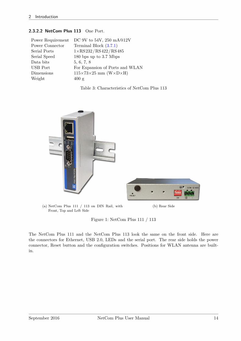
2.3.2.2 NetCom Plus 113 One Port.
Power Requirement DC 9V to 54V, 250 mA@12VPower Connector Terminal Block (3.7.1)Serial Ports 1×RS232/RS422/RS485Serial Speed 180 bps up to 3.7 MbpsData bits 5, 6, 7, 8USB Port For Expansion of Ports and WLANDimensions 115×73×25 mm (W×D×H)Weight 400 g
Table 3: Characteristics of NetCom Plus 113
(a) NetCom Plus 111 / 113 on DIN Rail, withFront, Top and Left Side
(b) Rear Side
Figure 1: NetCom Plus 111 / 113
The NetCom Plus 111 and the NetCom Plus 113 look the same on the front side. Here arethe connectors for Ethernet, USB 2.0, LEDs and the serial port. The rear side holds the powerconnector, Reset button and the configuration switches. Positions for WLAN antenna are built-in.
September 2016 NetCom Plus User Manual 14
2 Introduction
2.3.2.3 NetCom Plus 211 Two Ports.
Power Requirement DC 9V to 54V, 250 mA@12VPower Connector Terminal Block (3.7.1)Serial Ports 2×RS232Serial Speed 180 bps up to 1.0 MbpsData bits 5, 6, 7, 8USB Port For Expansion of Ports and WLANDimensions 115×73×25 mm (W×D×H)Weight 400 g
Table 4: Characteristics of NetCom Plus 211
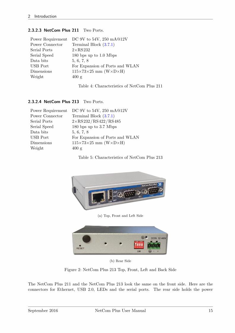
2.3.2.4 NetCom Plus 213 Two Ports.
Power Requirement DC 9V to 54V, 250 mA@12VPower Connector Terminal Block (3.7.1)Serial Ports 2×RS232/RS422/RS485Serial Speed 180 bps up to 3.7 MbpsData bits 5, 6, 7, 8USB Port For Expansion of Ports and WLANDimensions 115×73×25 mm (W×D×H)Weight 400 g
Table 5: Characteristics of NetCom Plus 213
(a) Top, Front and Left Side
(b) Rear Side
Figure 2: NetCom Plus 213 Top, Front, Left and Back Side
The NetCom Plus 211 and the NetCom Plus 213 look the same on the front side. Here are theconnectors for Ethernet, USB 2.0, LEDs and the serial ports. The rear side holds the power
September 2016 NetCom Plus User Manual 15

2 Introduction
connector, Reset button and the configuration switches. DIN Rail mounting clamp is fixed here.Positions for WLAN antenna are built-in.
2.3.2.5 NetCom Plus 411 Four Ports.
Power Requirement DC 9V to 54V, 600 mA@12VPower Connector Terminal Block (3.7.1)Serial Ports 4×RS232Serial Speed 180 bps up to 1.0 MbpsData bits 7, 8USB Port For Expansion of Ports and WLANDimensions 196×147×44 mm (W×D×H)Weight 900 g
Table 6: Characteristics of NetCom Plus 411
2.3.2.6 NetCom Plus 411 POE Four Ports.
Power Requirement DC 15V to 54V, 600 mA@15V(DC 15V to 54V on some samples)
Power Connector Terminal Block (3.7.1)Power Alternative Power over Ethernet PoE 802.3af Class 0Serial Ports 4×RS232Serial Speed 180 bps up to 500 kbpsData bits 7, 8Dimensions 196×147×44 mm (W×D×H)Weight 900 g
Table 7: Characteristics of NetCom Plus 411 POE
Note: RDY (Ready) LED is blue
2.3.2.7 NetCom Plus 413 Four Ports.
Power Requirement DC 9V to 54V, 600 mA@12VPower Connector Terminal Block (3.7.1)mPCIe Slot Optional, for 3G/4G modemsLED 3G Orange If mobile network is availableSerial Ports 4×RS232/RS422/RS485Serial Speed 180 bps up to 3.0 MbpsData bits 7, 8USB Port For Expansion of Ports and WLANDimensions 196×147×44 mm (W×D×H)Weight 900 g
Table 8: Characteristics of NetCom Plus 413
September 2016 NetCom Plus User Manual 16
2 Introduction
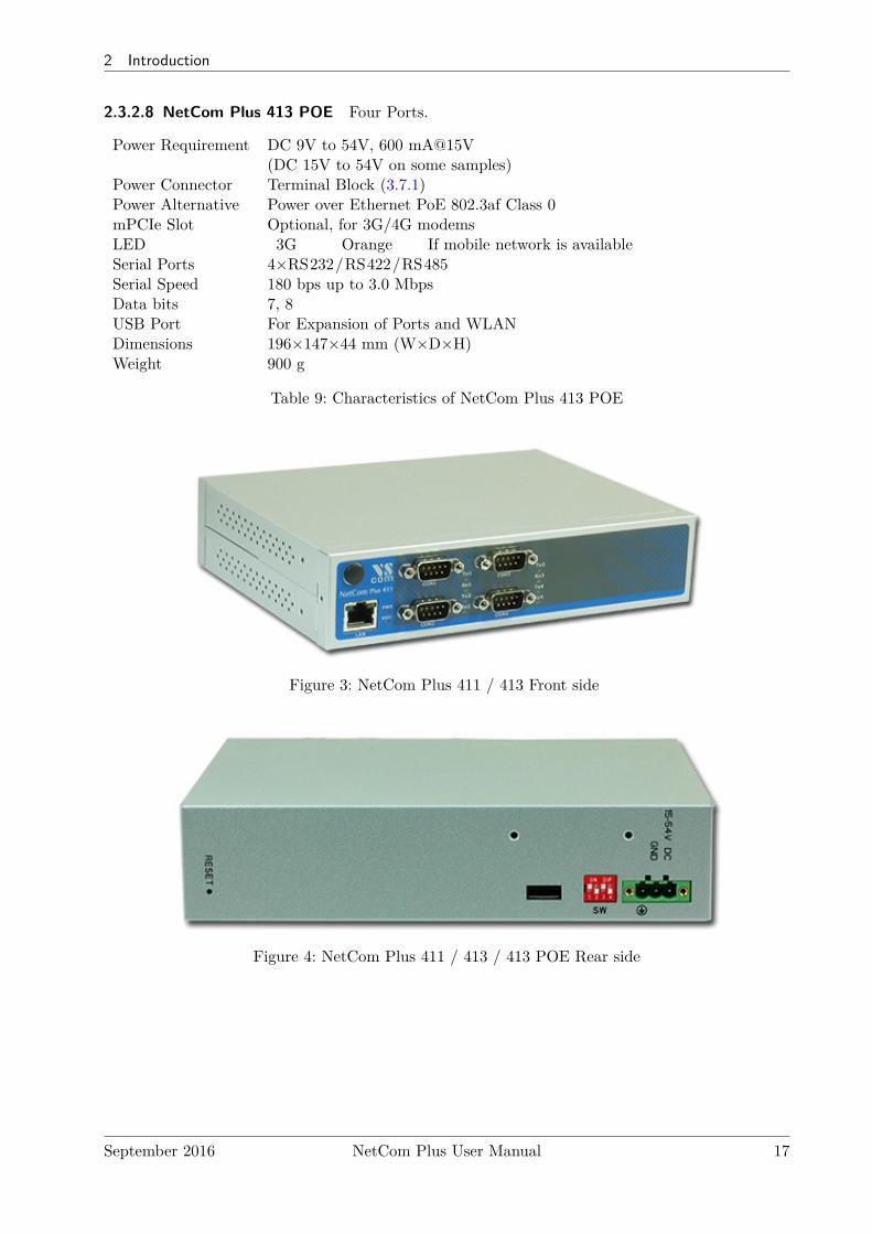
2.3.2.8 NetCom Plus 413 POE Four Ports.
Power Requirement DC 9V to 54V, 600 mA@15V(DC 15V to 54V on some samples)
Power Connector Terminal Block (3.7.1)Power Alternative Power over Ethernet PoE 802.3af Class 0mPCIe Slot Optional, for 3G/4G modemsLED 3G Orange If mobile network is availableSerial Ports 4×RS232/RS422/RS485Serial Speed 180 bps up to 3.0 MbpsData bits 7, 8USB Port For Expansion of Ports and WLANDimensions 196×147×44 mm (W×D×H)Weight 900 g
Table 9: Characteristics of NetCom Plus 413 POE
Figure 3: NetCom Plus 411 / 413 Front side
Figure 4: NetCom Plus 411 / 413 / 413 POE Rear side
September 2016 NetCom Plus User Manual 17
2 Introduction
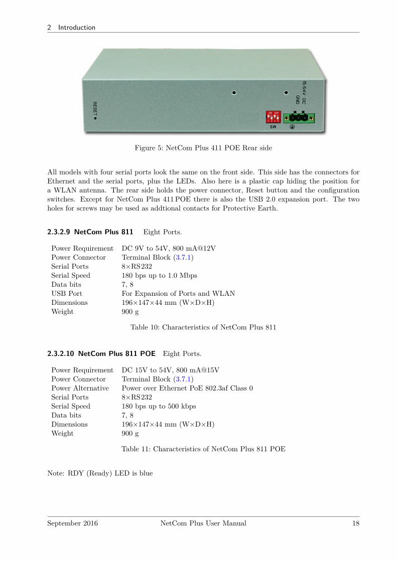
Figure 5: NetCom Plus 411 POE Rear side
All models with four serial ports look the same on the front side. This side has the connectors forEthernet and the serial ports, plus the LEDs. Also here is a plastic cap hiding the position fora WLAN antenna. The rear side holds the power connector, Reset button and the configurationswitches. Except for NetCom Plus 411POE there is also the USB 2.0 expansion port. The twoholes for screws may be used as addtional contacts for Protective Earth.
2.3.2.9 NetCom Plus 811 Eight Ports.
Power Requirement DC 9V to 54V, 800 mA@12VPower Connector Terminal Block (3.7.1)Serial Ports 8×RS232Serial Speed 180 bps up to 1.0 MbpsData bits 7, 8USB Port For Expansion of Ports and WLANDimensions 196×147×44 mm (W×D×H)Weight 900 g
Table 10: Characteristics of NetCom Plus 811
2.3.2.10 NetCom Plus 811 POE Eight Ports.
Power Requirement DC 15V to 54V, 800 mA@15VPower Connector Terminal Block (3.7.1)Power Alternative Power over Ethernet PoE 802.3af Class 0Serial Ports 8×RS232Serial Speed 180 bps up to 500 kbpsData bits 7, 8Dimensions 196×147×44 mm (W×D×H)Weight 900 g
Table 11: Characteristics of NetCom Plus 811 POE
Note: RDY (Ready) LED is blue
September 2016 NetCom Plus User Manual 18
2 Introduction
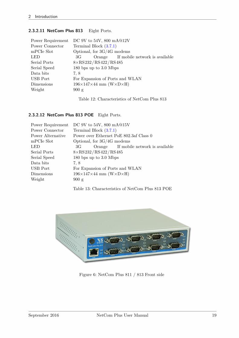
2.3.2.11 NetCom Plus 813 Eight Ports.
Power Requirement DC 9V to 54V, 800 mA@12VPower Connector Terminal Block (3.7.1)mPCIe Slot Optional, for 3G/4G modemsLED 3G Orange If mobile network is availableSerial Ports 8×RS232/RS422/RS485Serial Speed 180 bps up to 3.0 MbpsData bits 7, 8USB Port For Expansion of Ports and WLANDimensions 196×147×44 mm (W×D×H)Weight 900 g
Table 12: Characteristics of NetCom Plus 813
2.3.2.12 NetCom Plus 813 POE Eight Ports.
Power Requirement DC 9V to 54V, 800 mA@15VPower Connector Terminal Block (3.7.1)Power Alternative Power over Ethernet PoE 802.3af Class 0mPCIe Slot Optional, for 3G/4G modemsLED 3G Orange If mobile network is availableSerial Ports 8×RS232/RS422/RS485Serial Speed 180 bps up to 3.0 MbpsData bits 7, 8USB Port For Expansion of Ports and WLANDimensions 196×147×44 mm (W×D×H)Weight 900 g
Table 13: Characteristics of NetCom Plus 813 POE
Figure 6: NetCom Plus 811 / 813 Front side
September 2016 NetCom Plus User Manual 19
2 Introduction
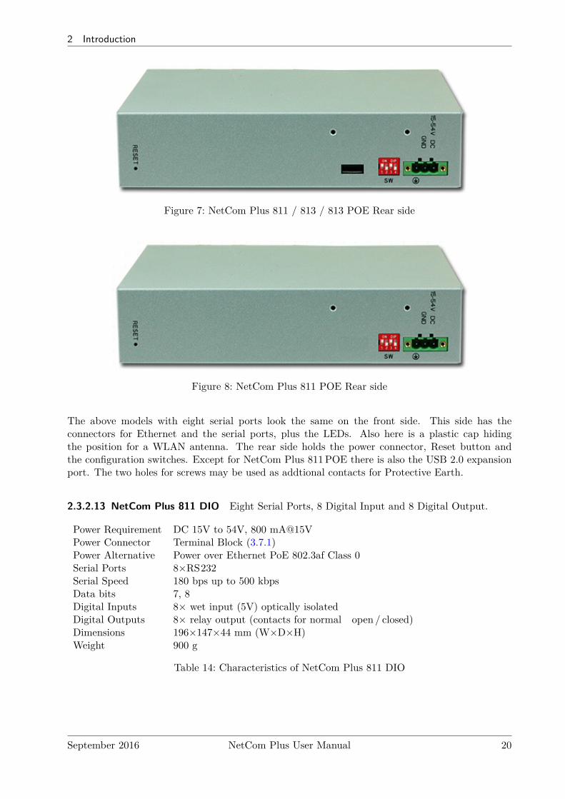
Figure 7: NetCom Plus 811 / 813 / 813 POE Rear side
Figure 8: NetCom Plus 811 POE Rear side
The above models with eight serial ports look the same on the front side. This side has theconnectors for Ethernet and the serial ports, plus the LEDs. Also here is a plastic cap hidingthe position for a WLAN antenna. The rear side holds the power connector, Reset button andthe configuration switches. Except for NetCom Plus 811POE there is also the USB 2.0 expansionport. The two holes for screws may be used as addtional contacts for Protective Earth.
2.3.2.13 NetCom Plus 811 DIO Eight Serial Ports, 8 Digital Input and 8 Digital Output.
Power Requirement DC 15V to 54V, 800 mA@15VPower Connector Terminal Block (3.7.1)Power Alternative Power over Ethernet PoE 802.3af Class 0Serial Ports 8×RS232Serial Speed 180 bps up to 500 kbpsData bits 7, 8Digital Inputs 8× wet input (5V) optically isolatedDigital Outputs 8× relay output (contacts for normal open / closed)Dimensions 196×147×44 mm (W×D×H)Weight 900 g
Table 14: Characteristics of NetCom Plus 811 DIO
September 2016 NetCom Plus User Manual 20
2 Introduction
(a) NetCom Plus 811 DIO Front side
(b) NetCom Plus 811 DIO Rear side
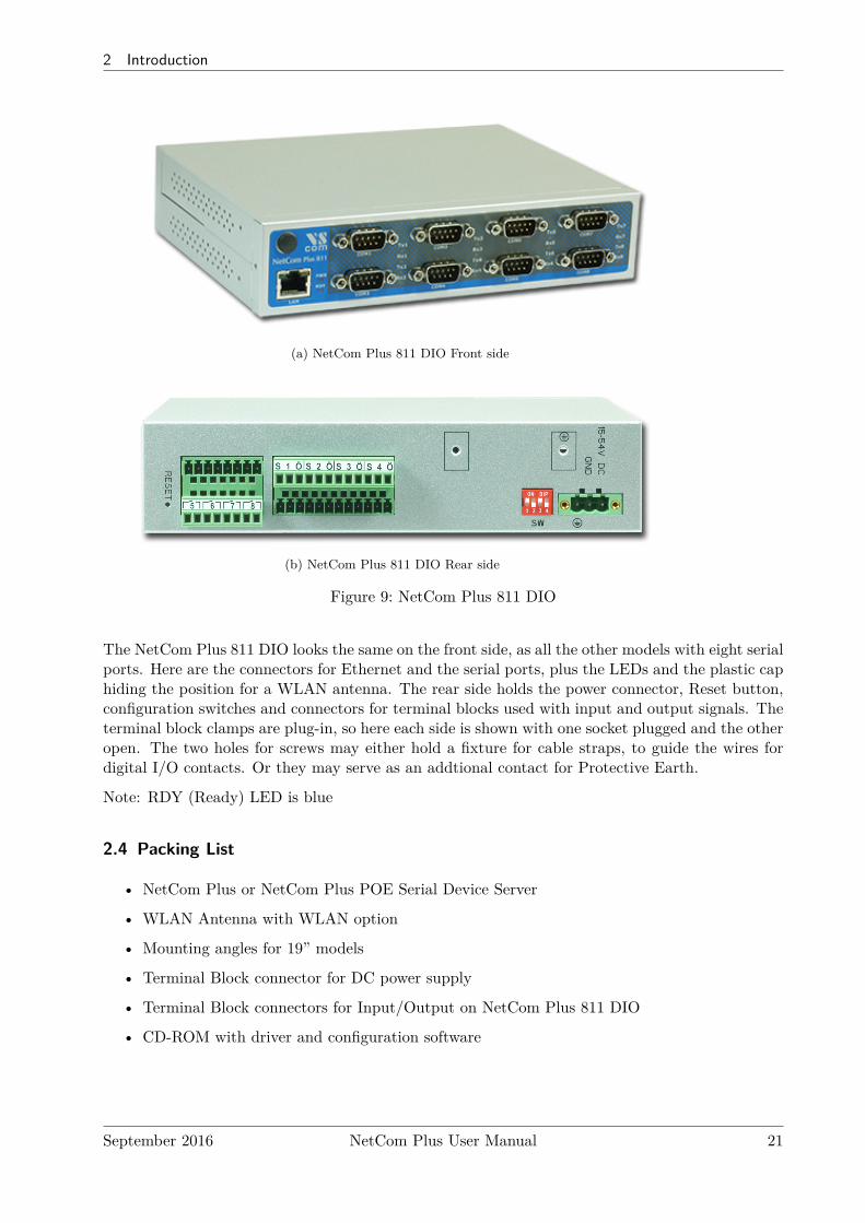
Figure 9: NetCom Plus 811 DIO
The NetCom Plus 811 DIO looks the same on the front side, as all the other models with eight serialports. Here are the connectors for Ethernet and the serial ports, plus the LEDs and the plastic caphiding the position for a WLAN antenna. The rear side holds the power connector, Reset button,configuration switches and connectors for terminal blocks used with input and output signals. Theterminal block clamps are plug-in, so here each side is shown with one socket plugged and the otheropen. The two holes for screws may either hold a fixture for cable straps, to guide the wires fordigital I/O contacts. Or they may serve as an addtional contact for Protective Earth.
Note: RDY (Ready) LED is blue
2.4 Packing List
• NetCom Plus or NetCom Plus POE Serial Device Server
• WLAN Antenna with WLAN option
• Mounting angles for 19” models
• Terminal Block connector for DC power supply
• Terminal Block connectors for Input/Output on NetCom Plus 811 DIO
• CD-ROM with driver and configuration software
September 2016 NetCom Plus User Manual 21
3 Hardware Description
3 Hardware Description
This section focuses on the options provided by the hardware of NetCom Plus Serial DeviceServers.
3.1 Serial Port Configuration
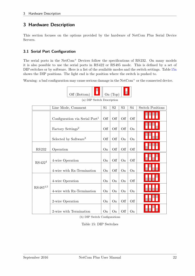
The serial ports in the NetCom+ Devices follow the specifications of RS232. On many modelsit is also possible to use the serial ports in RS422 or RS485 mode. This is defined by a set ofDIP switches or by software. Here is a list of the available modes and the switch settings. Table 15ashows the DIP positions. The light end is the position where the switch is pushed to.
Warning: a bad configuration may cause serious damage in the NetCom+ or the connected device.
Off (Bottom) On (Top)(a) DIP Switch Description
Line Mode, Comment S1 S2 S3 S4 Switch Positions
Configuration via Serial Port1 Off Off Off Off
Factory Settings2 Off Off Off On
Selected by Software3 Off Off On On
RS232 Operation On Off Off Off
RS4224 4-wire Operation On Off On Off
4-wire with Rx-Termination On Off On On
RS4854,5
4-wire Operation On On On Off
4-wire with Rx-Termination On On On On
2-wire Operation On On Off Off
2-wire with Termination On On Off On(b) DIP Switch Configurations
Table 15: DIP Switches
September 2016 NetCom Plus User Manual 22

3 Hardware Description
Note 1: »Configuration via Serial Port« is only effective on port 1 of the NetCom+ Server.Note 2: Factory Settings are restored on Power-Up/Reset of the NetCom+.Note 3: The Master DIP switches configure all serial ports of a NetCom+ to a common
operation mode. If diversity in line operation modes is intended, the switch mustbe set to »Selected by Software«, and the configuration may be done via SerialPort, Telnet, Web browser or SNMP.
Note 4: Line operation modes of RS422 and RS485 are not available on NetCom Plus111 / 211 / 411 / 811 (incl. POE).
Note 5: In RS485 mode the NetCom+ performs the required activation and disabling ofthe RS485 transmitter by an internal automatic. Application software does nothave to perform special operations.
USB–COM Plus modules may be added for port expansion. These are either configured by theirown DIP switches. Or when the 4- and 8-port modules are set for configuration by software, theoperation mode is controlled by the NetCom Plus in the same way as with the internal ports.
3.2 Serial Signal Assignment
It is of course important to know the exact location of the serial signals in the configured mode.Here is the table for the DSub-9 male connector. For RS232 the assignment is the same as on anyPC (Com1/2).
Pin RS232 RS422/485 4-wire RS485 2-wire1 DCD Tx− (A) Data− (A)2 RxD Tx+ (B) Data+ (B)3 TxD Rx+ (B)4 DTR Rx− (A)5 GND GND GND6 DSR7 RTS8 CTS9 RI
Table 16: Signal Assignment DSub-9 male
Figure 10: ConnectorDSub-9 male
Please note the GND signal in RS422 and RS485 modes. This signal must also be connected be-tween the serial devices. So in reality there is neither a 2-wire nor a 4-wire connection. With the ex-ception of very special configurations, a serial cable without GND violates the specifications for RS422 and RS485. Signal RI is only available in RS232 mode on NetCom Plus 111 /113 / 211 / 213.
On USB–COM Plus modules used for Port Expansion the signal assignment is the same as onNetCom Plus. Also signal RI is only available with one and two ports.
September 2016 NetCom Plus User Manual 23
3 Hardware Description
3.3 RS422/485 Electrical Configuration
In typical RS422 and RS485 installations certain electric conditions have to be configured. Simplyconnecting cables is not enough to fulfill the specifications of RS422 and RS485.
For ease of installations the NetCom Plus Serial Device Servers provide the function for often usedTermination. This is activated by selecting the appropriate line operation mode via DIPSwitches(table 15) or by software.The electrical properties of USB–COM Plus serial ports are identical.
3.3.1 Termination Resistors
The use of long communication lines in RS422 and RS485 mode requires the installation of ter-mination resistors. These must match the impedance of the cable. Typical cables in Twisted-Pairconfiguration have an impedance of about 120Ω. In RS422 and RS485 4-wire this resistor has tobe placed at the end(s) far from the sender, in RS485 2-wire the typical configuration requires oneresistor at each end of the cable.
The NetCom Plus Serial Device Servers provide a suitable termination resistor integrated in theline drivers, activation is done by selecting the appropriate operation mode.For values of impedance other than 120Ω the resistors have to be installed directly on the cable.
3.3.2 BIAS Function
RS485 requires a BIAS option for the communication lines. This will guarantee stable electricallevels on the cables, even at times when no station is transmitting data. Without BIAS there willbe noise on the cable, and sometimes receivers can not detect the first characters of a beginningcommunication.
The NetCom Plus Serial Device Servers do not need an explicit BIAS function. With terminationactive the idle state of the transmission line is at 0V, which is recognized as a positive level (logicone) in the receiver circuit. Other devices may require explicit BIAS for a higher voltage at idlestate, e.g. 100mV. In such situation attach that function directly to the cable.
3.4 Serial Port Simple Settings
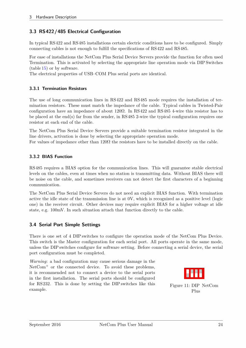
There is one set of 4 DIP switches to configure the operation mode of the NetCom Plus Device.This switch is the Master configuration for each serial port. All ports operate in the same mode,unless the DIP switches configure for software setting. Before connecting a serial device, the serialport configuration must be completed.
Warning: a bad configuration may cause serious damage in theNetCom+ or the connected device. To avoid these problems,it is recommended not to connect a device to the serial portsin the first installation. The serial ports should be configuredfor RS232. This is done by setting the DIP switches like thisexample.
Figure 11: DIP NetComPlus
September 2016 NetCom Plus User Manual 24
3 Hardware Description
3.5 Digital Input/Output
This function is only available on NetCom Plus 811 DIO. The input signals are optically isolatedfrom the system, and output function is realized by relay.
3.5.1 Input Connection
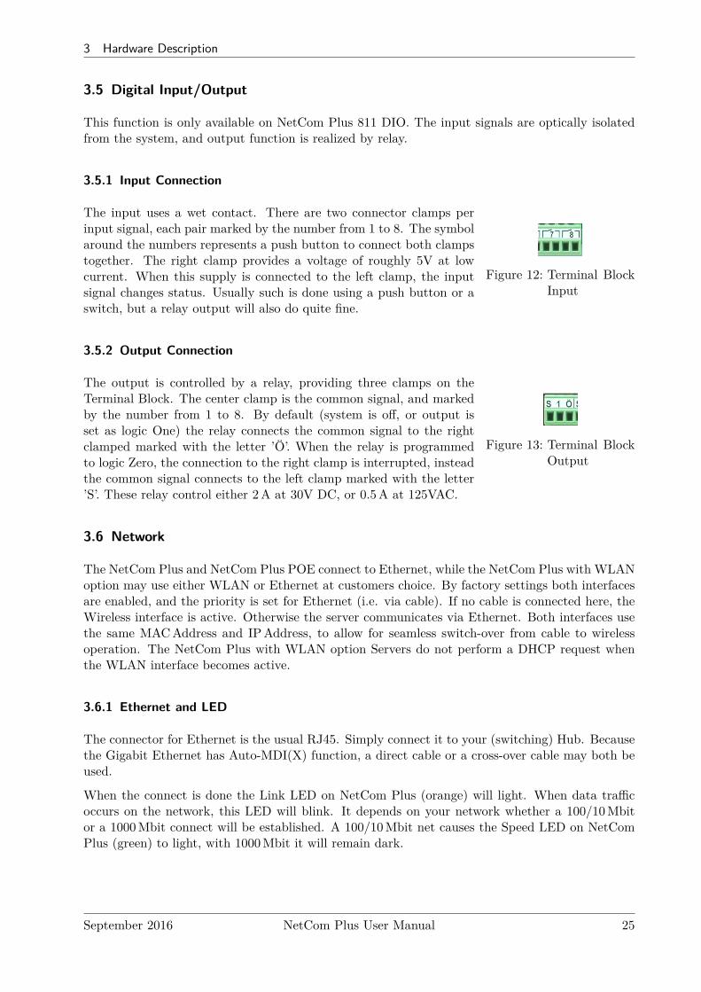
Figure 12: Terminal BlockInput
The input uses a wet contact. There are two connector clamps perinput signal, each pair marked by the number from 1 to 8. The symbolaround the numbers represents a push button to connect both clampstogether. The right clamp provides a voltage of roughly 5V at lowcurrent. When this supply is connected to the left clamp, the inputsignal changes status. Usually such is done using a push button or aswitch, but a relay output will also do quite fine.
3.5.2 Output Connection
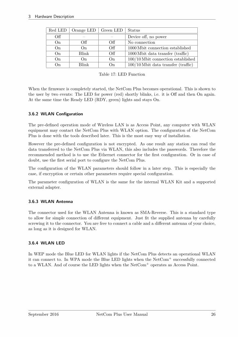
Figure 13: Terminal BlockOutput
The output is controlled by a relay, providing three clamps on theTerminal Block. The center clamp is the common signal, and markedby the number from 1 to 8. By default (system is off, or output isset as logic One) the relay connects the common signal to the rightclamped marked with the letter ’Ö’. When the relay is programmedto logic Zero, the connection to the right clamp is interrupted, insteadthe common signal connects to the left clamp marked with the letter’S’. These relay control either 2A at 30V DC, or 0.5A at 125VAC.
3.6 Network
The NetCom Plus and NetCom Plus POE connect to Ethernet, while the NetCom Plus with WLANoption may use either WLAN or Ethernet at customers choice. By factory settings both interfacesare enabled, and the priority is set for Ethernet (i.e. via cable). If no cable is connected here, theWireless interface is active. Otherwise the server communicates via Ethernet. Both interfaces usethe same MACAddress and IPAddress, to allow for seamless switch-over from cable to wirelessoperation. The NetCom Plus with WLAN option Servers do not perform a DHCP request whenthe WLAN interface becomes active.
3.6.1 Ethernet and LED
The connector for Ethernet is the usual RJ45. Simply connect it to your (switching) Hub. Becausethe Gigabit Ethernet has Auto-MDI(X) function, a direct cable or a cross-over cable may both beused.
When the connect is done the Link LED on NetCom Plus (orange) will light. When data trafficoccurs on the network, this LED will blink. It depends on your network whether a 100/10Mbitor a 1000Mbit connect will be established. A 100/10Mbit net causes the Speed LED on NetComPlus (green) to light, with 1000Mbit it will remain dark.
September 2016 NetCom Plus User Manual 25
3 Hardware Description
Red LED Orange LED Green LED StatusOff – – Device off, no powerOn Off Off No connectionOn On Off 1000Mbit connection establishedOn Blink Off 1000Mbit data transfer (traffic)On On On 100/10Mbit connection establishedOn Blink On 100/10Mbit data transfer (traffic)
Table 17: LED Function
When the firmware is completely started, the NetCom Plus becomes operational. This is shown tothe user by two events: The LED for power (red) shortly blinks, i.e. it is Off and then On again.At the same time the Ready LED (RDY, green) lights and stays On.
3.6.2 WLAN Configuration
The pre-defined operation mode of Wireless LAN is as Access Point, any computer with WLANequipment may contact the NetCom Plus with WLAN option. The configuration of the NetComPlus is done with the tools described later. This is the most easy way of installation.
However the pre-defined configuration is not encrypted. As one result any station can read thedata transferred to the NetCom Plus via WLAN, this also includes the passwords. Therefore therecommended method is to use the Ethernet connector for the first configuration. Or in case ofdoubt, use the first serial port to configure the NetCom Plus.
The configuration of the WLAN parameters should follow in a later step. This is especially thecase, if encryption or certain other parameters require special configuration.
The parameter configuration of WLAN is the same for the internal WLAN Kit and a supportedexternal adapter.
3.6.3 WLAN Antenna
The connector used for the WLAN Antenna is known as SMA-Reverse. This is a standard typeto allow for simple connection of different equipment. Just fit the supplied antenna by carefullyscrewing it to the connector. You are free to connect a cable and a different antenna of your choice,as long as it is designed for WLAN.
3.6.4 WLAN LED
In WEP mode the Blue LED for WLAN lights if the NetCom Plus detects an operational WLANit can connect to. In WPA mode the Blue LED lights when the NetCom+ successfully connectedto a WLAN. And of course the LED lights when the NetCom+ operates as Access Point.
September 2016 NetCom Plus User Manual 26
3 Hardware Description
3.7 Power Supply
The NetCom Plus devices are powered by a single 9-54V power supply. It requires 70 mA up to750 mA of current, depending on the device type and voltage supplied. Connect the cable to theTerminal Block at the rear side of NetCom Plus.
The NetCom Plus 411/811 POE devices are either powered by a single 15-54V power supply, inthe same way as the NetCom Plus and NetCom Plus with WLAN option devices; this also appliesto the NetCom Plus 811 DIO. The NetCom Plus 413/813 POE devices use the standard 9-54Vsupply.Or the NetCom Plus POE devices are powered via the network cable, connected to an Ethernetswitch with PoE function as IEEE802.3af. This switch is referenced as the PSE (Power SourcingEquipment), while the NetCom Plus POE is the PD (Powered Device). It indicates itself as aClass 0 device when sourced by the PSE. An external power adapter has priority over the PoEfunction.
3.7.1 Terminal Block Power
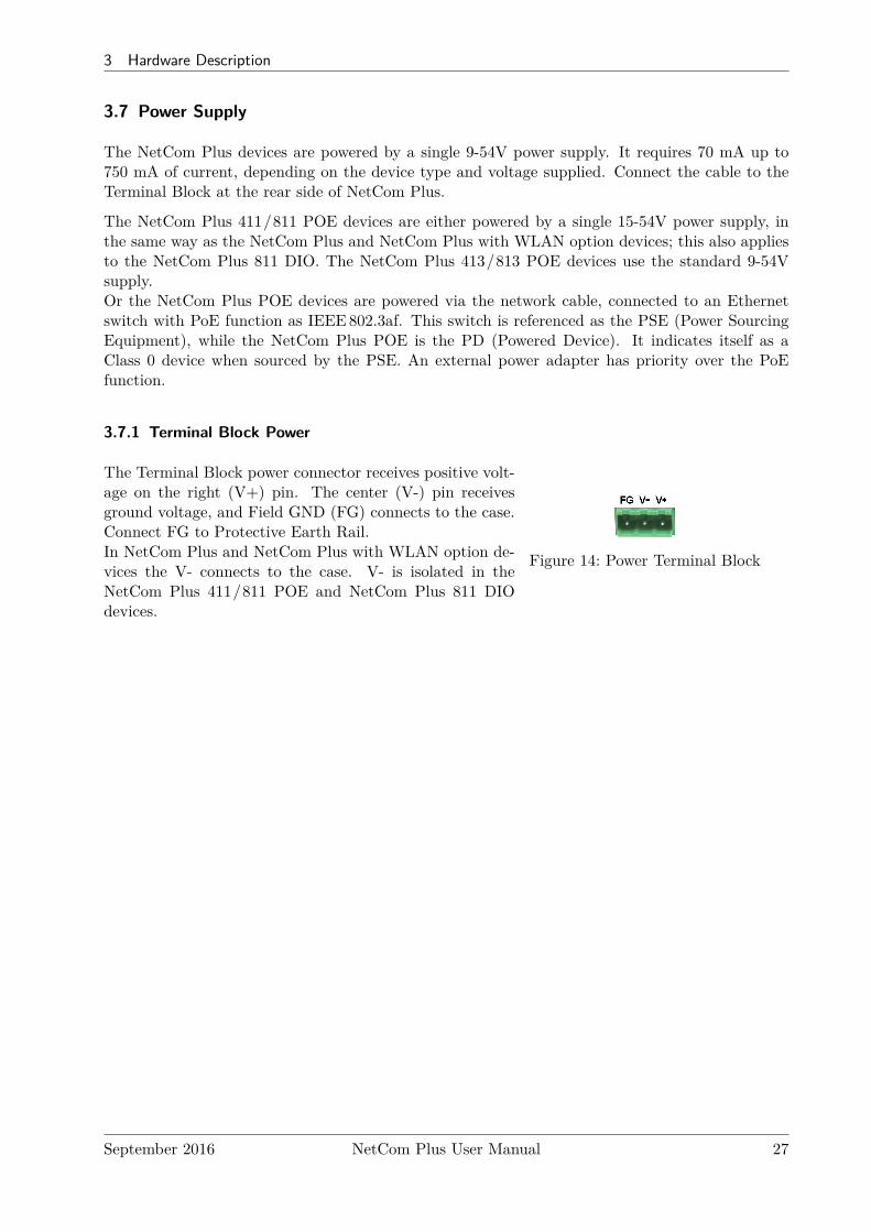
The Terminal Block power connector receives positive volt-age on the right (V+) pin. The center (V-) pin receivesground voltage, and Field GND (FG) connects to the case.Connect FG to Protective Earth Rail.In NetCom Plus and NetCom Plus with WLAN option de-vices the V- connects to the case. V- is isolated in theNetCom Plus 411/811 POE and NetCom Plus 811 DIOdevices.
Figure 14: Power Terminal Block
September 2016 NetCom Plus User Manual 27
4 Windows Virtual COM Driver
4 Windows Virtual COM Driver
This chapter covers the use of NetCom+ Devices via Virtual Com Ports installed by the supplieddriver software for Windows. Sections 4.1 to 4.3 describe in details the process of driver installationand removal, as well as updating. This first part here is for quick installation, so only the commonoptions are covered.
Section 4.4 provides the details of NetCom Plus Manager and also the options available with theVirtual Com Ports.
4.1 Installation Procedure
Before starting installation, it is essential to have an IP configuration ready for the NetCom+ Deviceto install. You may read the TCP/IP Description (section 13) below. The default configuration isbased on DHCP, which is fine in many networks. If in doubt, please ask your Network Administratorfor help. Further it is assumed the network access is functional. It is recommended to use Ethernetvia Hub or Cross-Over cable for configuration.
The following description is based on Windows 10. The installation on other configurations ofWindows is similar. The installation of drivers is described first. This is followed by a procedure toverify a correct installation. The last part of this section is about the uninstall or update processesof drivers and tools.
Drivers are provided for WindowsXP up to Windows 10, Windows Server 2003 up to 2008R2. Thex86 and x64Editions have separate drivers.
The drivers use the IPAddress of NetCom+ Servers to operate. So the configurationof the device should avoid to change that over time. This is either done via a staticIPAddress, or by proper configuration of the DHCP server. In the second casethe DHCP server shall recognize the NetCom+ by its MACAddress, and assign thesame IPAddress each time the device sends a request. All available DHCP Serverproducts provide such a function, even in SOHO routers.
4.1.1 Start the Installation Wizard
Figure 15: Installation Wizard
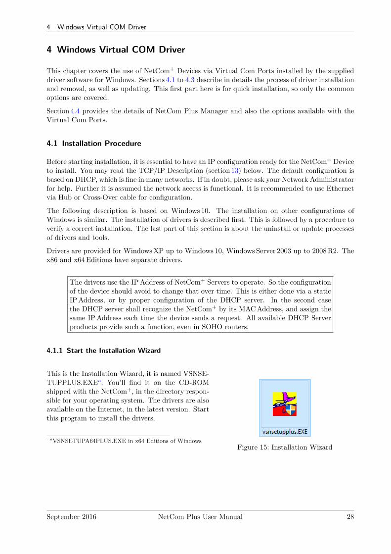
This is the Installation Wizard, it is named VSNSE-TUPPLUS.EXEa. You’ll find it on the CD-ROMshipped with the NetCom+, in the directory respon-sible for your operating system. The drivers are alsoavailable on the Internet, in the latest version. Startthis program to install the drivers.
aVSNSETUPA64PLUS.EXE in x64 Editions of Windows
September 2016 NetCom Plus User Manual 28
4 Windows Virtual COM Driver
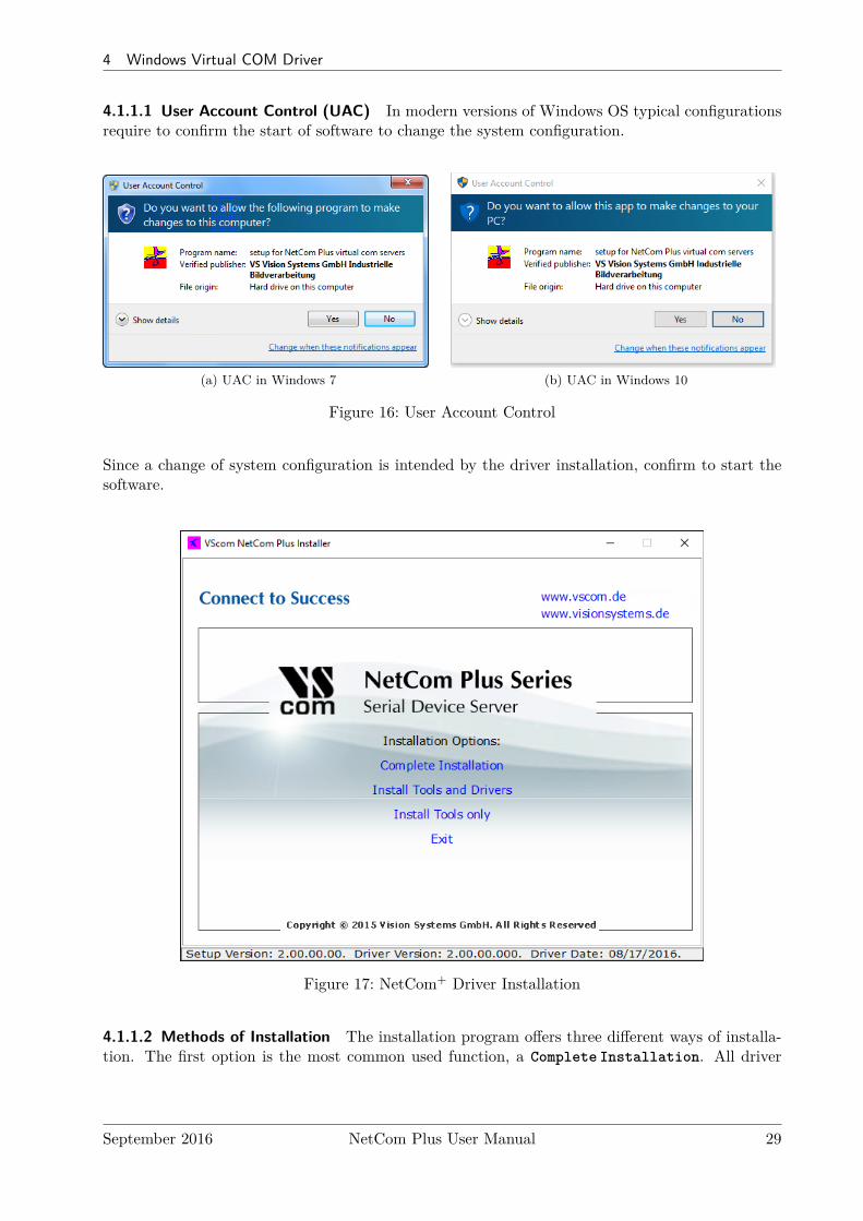
4.1.1.1 User Account Control (UAC) In modern versions of Windows OS typical configurationsrequire to confirm the start of software to change the system configuration.
(a) UAC in Windows 7 (b) UAC in Windows 10
Figure 16: User Account Control
Since a change of system configuration is intended by the driver installation, confirm to start thesoftware.
Figure 17: NetCom+ Driver Installation
4.1.1.2 Methods of Installation The installation program offers three different ways of installa-tion. The first option is the most common used function, a Complete Installation. All driver
September 2016 NetCom Plus User Manual 29
4 Windows Virtual COM Driver
files and tools are copied to the Windows system, and installed in the Start Menu. Further thedrivers are installed in the system, and the network is searched for available NetCom+. The serialports on these devices are installed as Virtual Com Ports in the system.The second option will Install Tools and Drivers. However the network is not searched forNetCom+ Devices. And of course no serial ports are installed in the system. This function isdesigned to prepare a computer for use of NetCom+ Virtual Com Ports, but the final installationshall be skipped for some reasons. For example the computer shall be shipped to a customer, andthe final installation is planned to happen there.Finally the third option is to Install Tools only, no drivers. At time of writing these tools are theNetCom Manager, as well as the uninstall and repair functions. This function should be selectedwhen the use of Virtual Com Port drivers is not intended. The NetCom+ Devices may be used inmany different operation modes covered later (6).
There are also some Hyperlinks, opening access to more recent driver versions.
This part of the manual documents the Complete Installation, so click this option.
Figure 18: Start Driver Installation
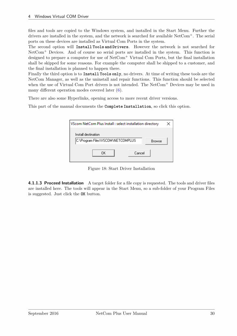
4.1.1.3 Proceed Installation A target folder for a file copy is requested. The tools and driver filesare installed here. The tools will appear in the Start Menu, so a sub-folder of your Program Filesis suggested. Just click the OK button.
September 2016 NetCom Plus User Manual 30
4 Windows Virtual COM Driver
Figure 19: Copy Driver Files
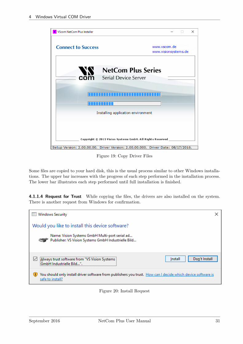
Some files are copied to your hard disk, this is the usual process similar to other Windows installa-tions. The upper bar increases with the progress of each step performed in the installation process.The lower bar illustrates each step performed until full installation is finished.
4.1.1.4 Request for Trust While copying the files, the drivers are also installed on the system.There is another request from Windows for confirmation.
Figure 20: Install Request
September 2016 NetCom Plus User Manual 31
4 Windows Virtual COM Driver
Note: No component is actually installed at this moment. Windows is just preparing to load thedrivers, once the NetCom Plus Manager instructs to do so. This request will come twice, to makeit more easy just tick the Always trust option.
4.1.2 Find and Configure NetCom+ Devices
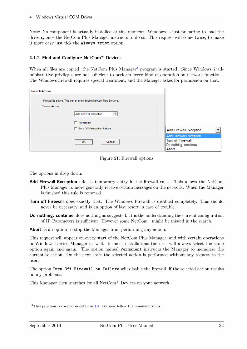
When all files are copied, the NetCom Plus Manager3 program is started. Since Windows 7 ad-ministrative privileges are not sufficient to perform every kind of operation on network functions.The Windows firewall requires special treatment, and the Manager askes for permission on that.
Figure 21: Firewall options
The options in drop down:
Add Firewall Exception adds a temporary entry in the firewall rules. This allows the NetComPlus Manager to more generally receive certain messages on the network. When the Manageris finished this rule is removed.
Turn off Firewall does exactly that. The Windows Firewall is disabled completely. This shouldnever be necessary, and is an option of last resort in case of trouble.
Do nothing, continue does nothing as suggested. It is the understanding the current configurationof IP Parameters is sufficient. However some NetCom+ might be missed in the search.
Abort is an option to stop the Manager from performing any action.
This request will appear on every start of the NetCom Plus Manager, and with certain operationsin Windows Device Manager as well. In most installations the user will always select the sameoption again and again. The option named Permanent instructs the Manager to memorize thecurrent selection. On the next start the selected action is performed without any request to theuser.
The option Turn Off Firewall on Failure will disable the firewall, if the selected action resultsin any problems.
This Manager then searches for all NetCom+ Devices on your network.
3This program is covered in detail in 4.4. For now follow the minimum steps.
September 2016 NetCom Plus User Manual 32
4 Windows Virtual COM Driver
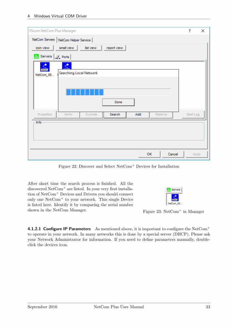
Figure 22: Discover and Select NetCom+ Devices for Installation
Figure 23: NetCom+ in Manager
After short time the search process is finished. All thediscovered NetCom+ are listed. In your very first installa-tion of NetCom+ Devices and Drivers you should connectonly one NetCom+ to your network. This single Deviceis listed here. Identify it by comparing the serial numbershown in the NetCom Manager.
4.1.2.1 Configure IP Parameters As mentioned above, it is important to configure the NetCom+
to operate in your network. In many networks this is done by a special server (DHCP). Please askyour Network Administrator for information. If you need to define parameters manually, double-click the devices icon.
September 2016 NetCom Plus User Manual 33
4 Windows Virtual COM Driver
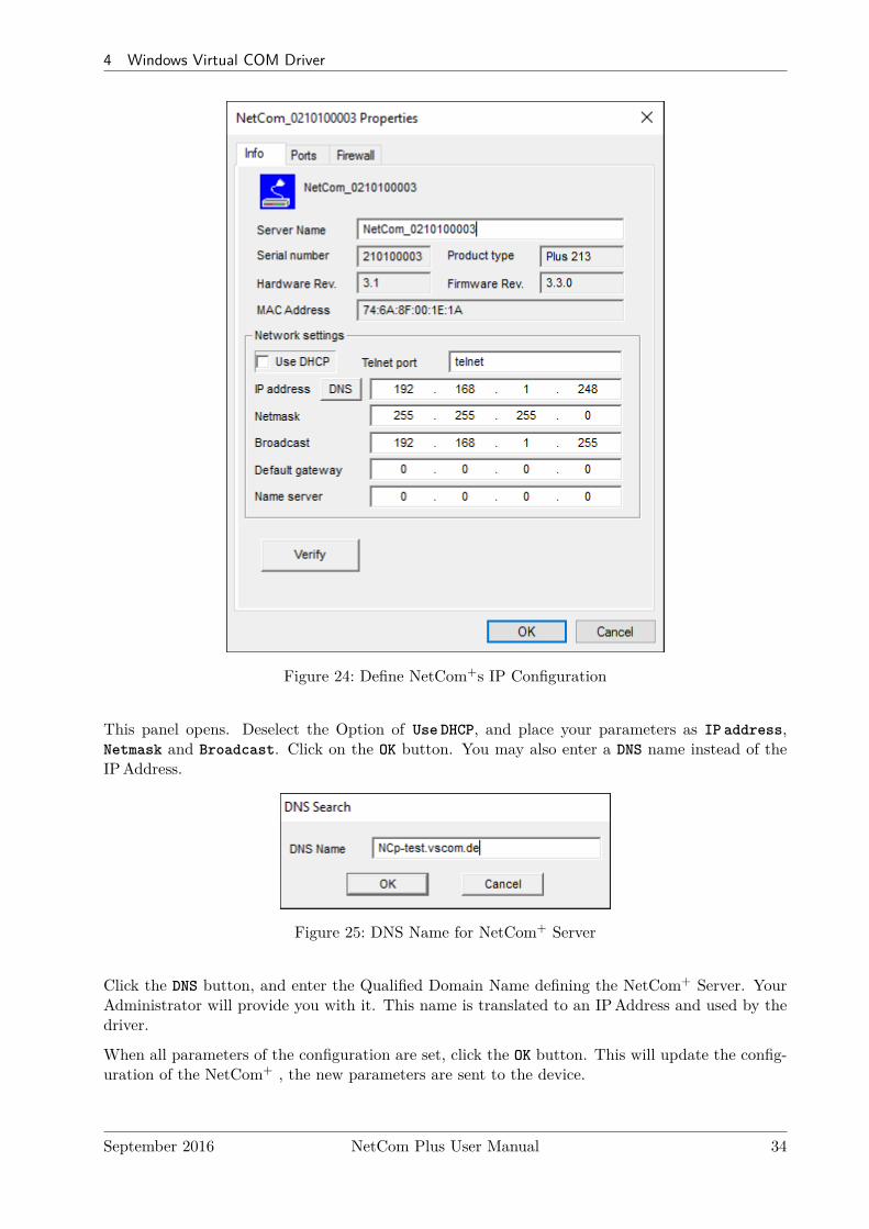
Figure 24: Define NetCom+s IP Configuration
This panel opens. Deselect the Option of Use DHCP, and place your parameters as IP address,Netmask and Broadcast. Click on the OK button. You may also enter a DNS name instead of theIPAddress.
Figure 25: DNS Name for NetCom+ Server
Click the DNS button, and enter the Qualified Domain Name defining the NetCom+ Server. YourAdministrator will provide you with it. This name is translated to an IPAddress and used by thedriver.
When all parameters of the configuration are set, click the OK button. This will update the config-uration of the NetCom+ , the new parameters are sent to the device.
September 2016 NetCom Plus User Manual 34
4 Windows Virtual COM Driver
Figure 26: Sending Parameters to a NetCom+
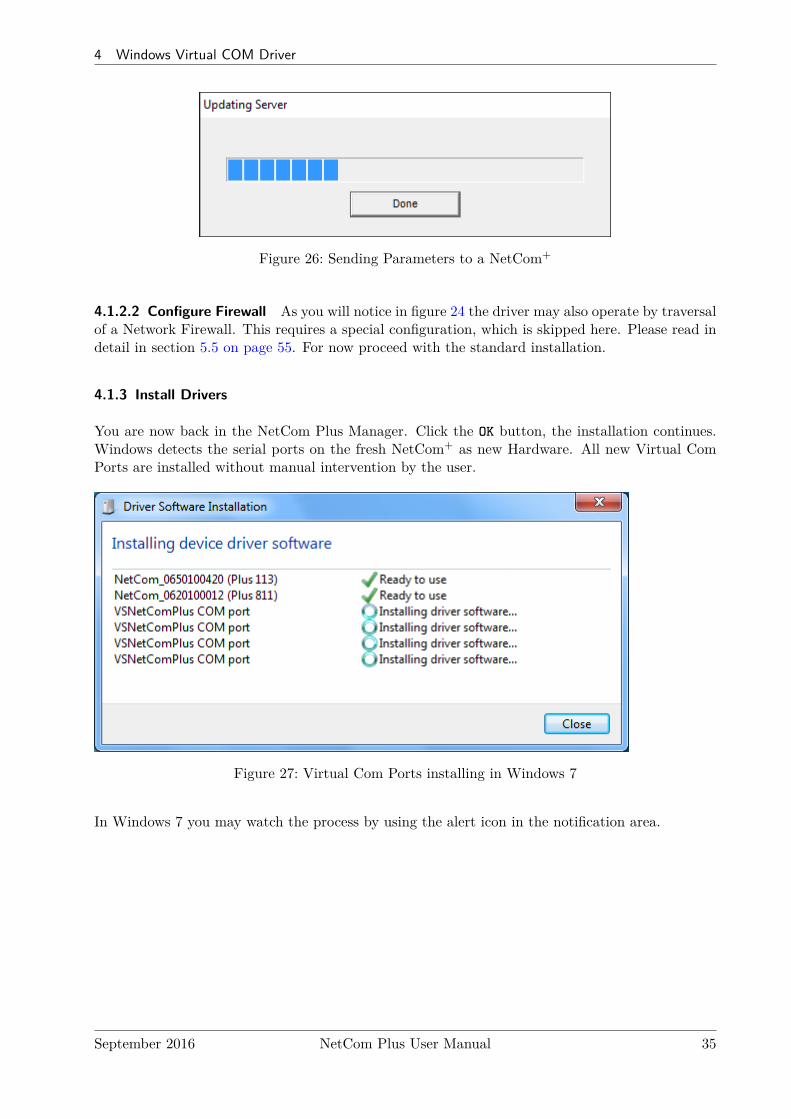
4.1.2.2 Configure Firewall As you will notice in figure 24 the driver may also operate by traversalof a Network Firewall. This requires a special configuration, which is skipped here. Please read indetail in section 5.5 on page 55. For now proceed with the standard installation.
4.1.3 Install Drivers
You are now back in the NetCom Plus Manager. Click the OK button, the installation continues.Windows detects the serial ports on the fresh NetCom+ as new Hardware. All new Virtual ComPorts are installed without manual intervention by the user.
Figure 27: Virtual Com Ports installing in Windows 7
In Windows 7 you may watch the process by using the alert icon in the notification area.
September 2016 NetCom Plus User Manual 35
4 Windows Virtual COM Driver
(a) Server first
(b) then Com Ports
Figure 28: Virtual Com Ports installing in Windows 10
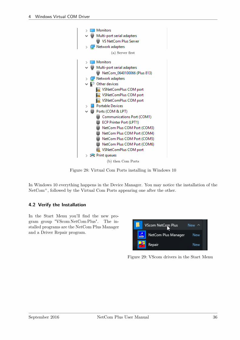
In Windows 10 everything happens in the Device Manager. You may notice the installation of theNetCom+, followed by the Virtual Com Ports appearing one after the other.
4.2 Verify the Installation
Figure 29: VScom drivers in the Start Menu
In the Start Menu you’ll find the new pro-gram group "VScomNetComPlus". The in-stalled programs are the NetCom Plus Managerand a Driver Repair program.
September 2016 NetCom Plus User Manual 36
4 Windows Virtual COM Driver
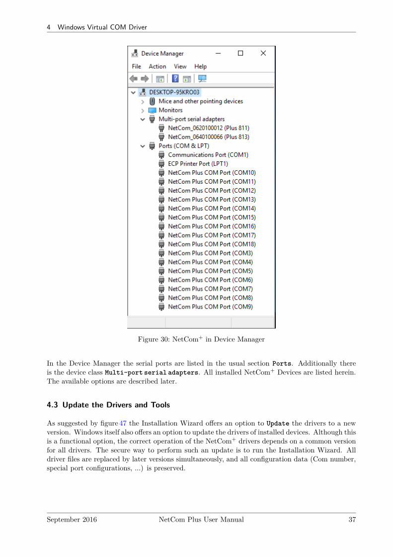
Figure 30: NetCom+ in Device Manager
In the Device Manager the serial ports are listed in the usual section Ports. Additionally thereis the device class Multi-port serial adapters. All installed NetCom+ Devices are listed herein.The available options are described later.
4.3 Update the Drivers and Tools
As suggested by figure 47 the Installation Wizard offers an option to Update the drivers to a newversion. Windows itself also offers an option to update the drivers of installed devices. Although thisis a functional option, the correct operation of the NetCom+ drivers depends on a common versionfor all drivers. The secure way to perform such an update is to run the Installation Wizard. Alldriver files are replaced by later versions simultaneously, and all configuration data (Com number,special port configurations, ...) is preserved.
September 2016 NetCom Plus User Manual 37
4 Windows Virtual COM Driver
4.4 Configuration of the Virtual COM Driver
If properly configured, the serial ports of the NetCom+ Devices appear as Virtual Com Ports inyour computer. The "virtual" means, in the computer is no real hardware related to the serial port,however the driver offers the full functionality of a serial port to the system. The interface used bythe driver is VCOMM, which in turn is supported by the Windows API. So Windows does not seea difference to Com1, and also no application should detect the change.
When the serial ports are installed by the Virtual Com driver software, any application may usethem. In the Device Manager they appear as NetCom Plus COM Port (figure 30). Without specialtests a program does not see a difference between Com1 and the virtual Com7. For example theHyper Terminal4 program has no problem to communicate through these Virtual Com Port. Andthis situation is common amongst most programs.
4.4.1 Configure the Serial Ports
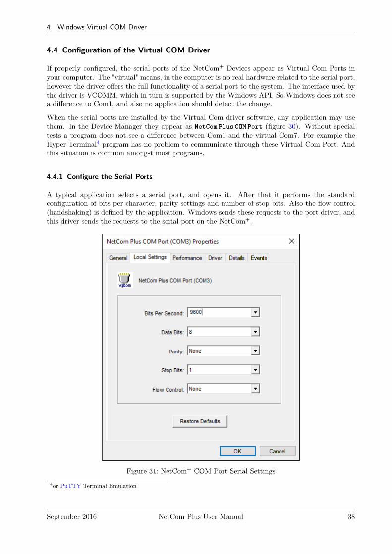
A typical application selects a serial port, and opens it. After that it performs the standardconfiguration of bits per character, parity settings and number of stop bits. Also the flow control(handshaking) is defined by the application. Windows sends these requests to the port driver, andthis driver sends the requests to the serial port on the NetCom+.
Figure 31: NetCom+ COM Port Serial Settings4or PuTTY Terminal Emulation
September 2016 NetCom Plus User Manual 38
4 Windows Virtual COM Driver
The same parameters may be pre-configured in the Device Manager. This is done via the Propertiesof the NetCom Plus COM Port. In the Local Settings tab these standard parameters are defined.Since most programs configure these parameters by themselves, the values are very rarely used. Atypical situation is a serial printer attached to this virtual port.
4.4.2 Performance Issues
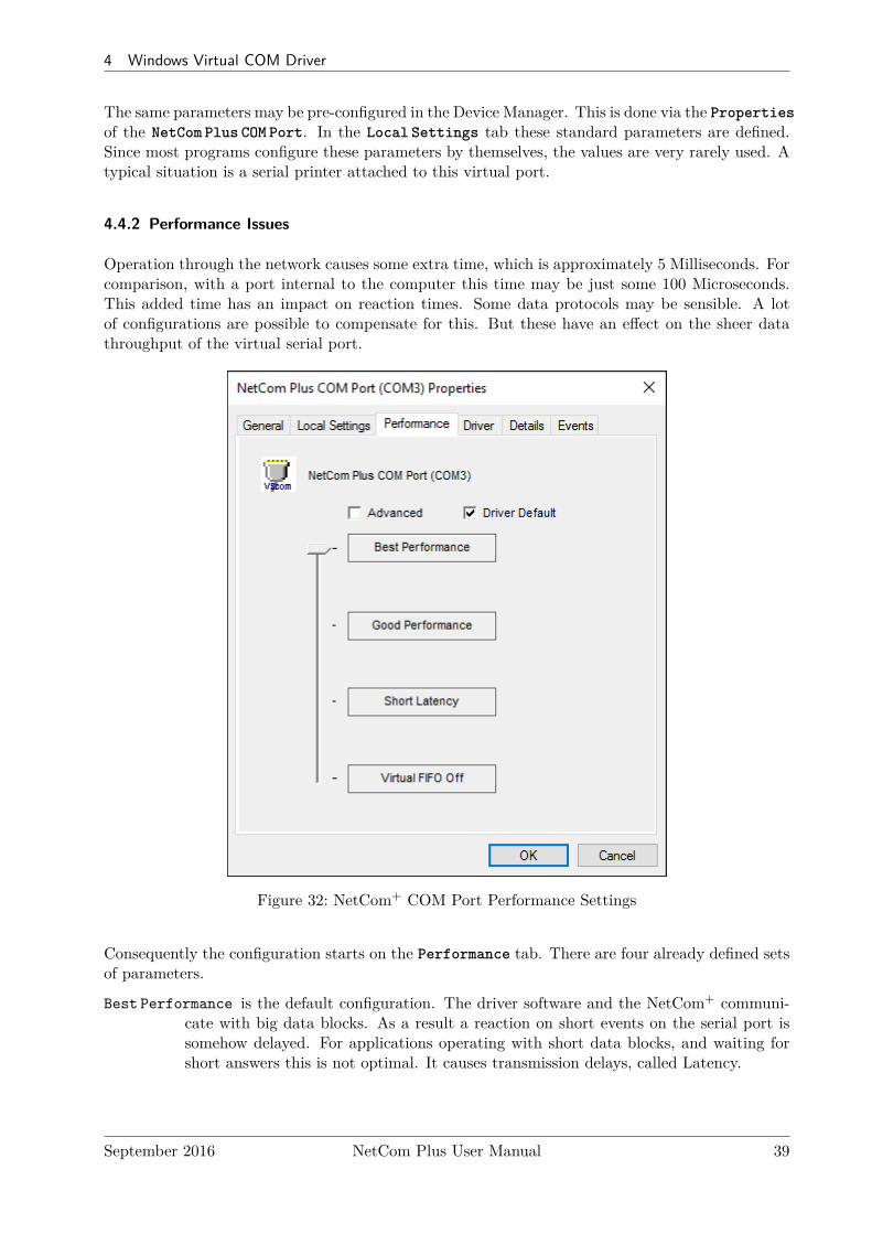
Operation through the network causes some extra time, which is approximately 5 Milliseconds. Forcomparison, with a port internal to the computer this time may be just some 100 Microseconds.This added time has an impact on reaction times. Some data protocols may be sensible. A lotof configurations are possible to compensate for this. But these have an effect on the sheer datathroughput of the virtual serial port.
Figure 32: NetCom+ COM Port Performance Settings
Consequently the configuration starts on the Performance tab. There are four already defined setsof parameters.
Best Performance is the default configuration. The driver software and the NetCom+ communi-cate with big data blocks. As a result a reaction on short events on the serial port issomehow delayed. For applications operating with short data blocks, and waiting forshort answers this is not optimal. It causes transmission delays, called Latency.
September 2016 NetCom Plus User Manual 39

4 Windows Virtual COM Driver
Good Performance uses smaller blocks. The Latency may be reduced a little bit, depending on theapplication. But the impact on the data throughput is small.
Short Latency mimics a 16C550 with full FIFO enabled, but no network timeouts will occur. Thismeans the block size is 16, quite small for network operations.
Virtual FIFO Off simulates a deactivated FIFO, which is the fastest setting in terms of latency.The port is configured as if the FIFO is off, buffers are configured to never wait for atimeout, hence gaining in best reaction times. The FIFO buffers are not deactivated inreality, they are still used to prevent data loss.
Driver Defaults returns to the standard settings when enabled.
Advanced opens access to detailed configuration of the operation parameters.
September 2016 NetCom Plus User Manual 40
4 Windows Virtual COM Driver
4.4.3 Network & Misc Properties
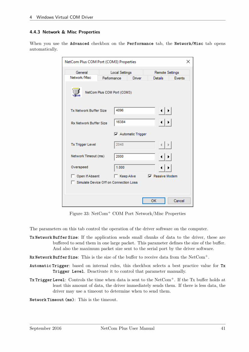
When you use the Advanced checkbox on the Performance tab, the Network/Misc tab opensautomatically.
Figure 33: NetCom+ COM Port Network/Misc Properties
The parameters on this tab control the operation of the driver software on the computer.
Tx Network Buffer Size: If the application sends small chunks of data to the driver, these arebuffered to send them in one large packet. This parameter defines the size of the buffer.And also the maximum packet size sent to the serial port by the driver software.
Rx Network Buffer Size: This is the size of the buffer to receive data from the NetCom+.
Automatic Trigger: based on internal rules, this checkbox selects a best practice value for TxTrigger Level. Deactivate it to control that parameter manually.
Tx Trigger Level: Controls the time when data is sent to the NetCom+. If the Tx buffer holds atleast this amount of data, the driver immediately sends them. If there is less data, thedriver may use a timeout to determine when to send them.
Network Timeout (ms): This is the timeout.
September 2016 NetCom Plus User Manual 41
4 Windows Virtual COM Driver
Overspeed: This is a special option, not really related to network communication. There are oldapplications, limited in the maximum speed. With Overspeed you define a multiplier.The baudrate requested by the application is multiplied with this factor. The result issent to the NetCom+ to configure the serial port. E.g. the application may be limitedto 38,400 bps, but there is a modem capable of 230,400 bps on the serial port. SetOverspeed to a value of 6.000, and configure the application to use 38,400 bps.
Open If Absent: The NetCom+ may be used from a computer with a Dial-Up connection. Whenthis option is used, the driver will delay the connection to NetCom+s serial port. Evenwhen an application opens the port and configures the parameters, no command issent. The connection is established when data is sent to the NetCom+, or when statusinformation is requested.
Keep Alive: This option will periodically send control information to the NetCom+ to check ifthe connection is still operational. As a second effect a Dial-Up connection will notautomatically close.
Passive Modem: This option controls how often the driver retrieves Modem status information fromthe NetCom+. If activated, the driver never asks for the modem status. Instead theNetCom+ informs the driver of any changes. If an application frequently requests theModem status, it gets the last value received. On slow networks like the Internet thisoption is recommended.If inactive, the driver software retrieves the Modem status from the NetCom+ serialport each time the application requests it, but with a maximum frequency of 10 persecond. If the latest retrieved information is not older than 100 milliseconds, this valueis returned.
Simulate Device Off on Connection Loss: When this option is enabled, the NetCom+ driver doesnot attempt to preserve transmitted data. If on a normal serial port the connecteddevice is switched off, all data sent to this device gets lost. NetCom+ simulates thisbehavior. All data sent from the application to the driver is discarded, when the TCPconnection to the NetCom+ is lost. The NetCom+ driver attempts to re-establish theconnection in regular intervals. When the NetCom+ is available again, data may betransferred from then on.
September 2016 NetCom Plus User Manual 42
4 Windows Virtual COM Driver
4.4.4 Remote Settings Properties
The other panel created by activating the Advanced checkbox on the Performance tab, is theRemote Settings tab.
Figure 34: NetCom+ COM Port Remote Settings Properties
The parameters on this tab control the operation of the serial port on the NetCom+ Device. Theyare defined and activated by the driver software.
Tx Trigger Level: The serial port on the NetCom+ Device buffers data for transmission to externaldevices. If the amount of data in this buffer drops below this level, the NetCom+ iscapable to receive new data. It will send a related event to the driver software.
Rx Trigger Level: When the serial port has received this amount of data, these are sent to thedriver on the connected computer. If the amount is less than this, the NetCom+ appliesa timeout of about 5 character times. This means the timeout varies with the serialtransmission speed.
The Remote Flow Control panel signals the NetCom+ to perform the handshake on its own. Thisis necessary, because the network delay of some milliseconds is to long for reliable operation inmany situations.
September 2016 NetCom Plus User Manual 43
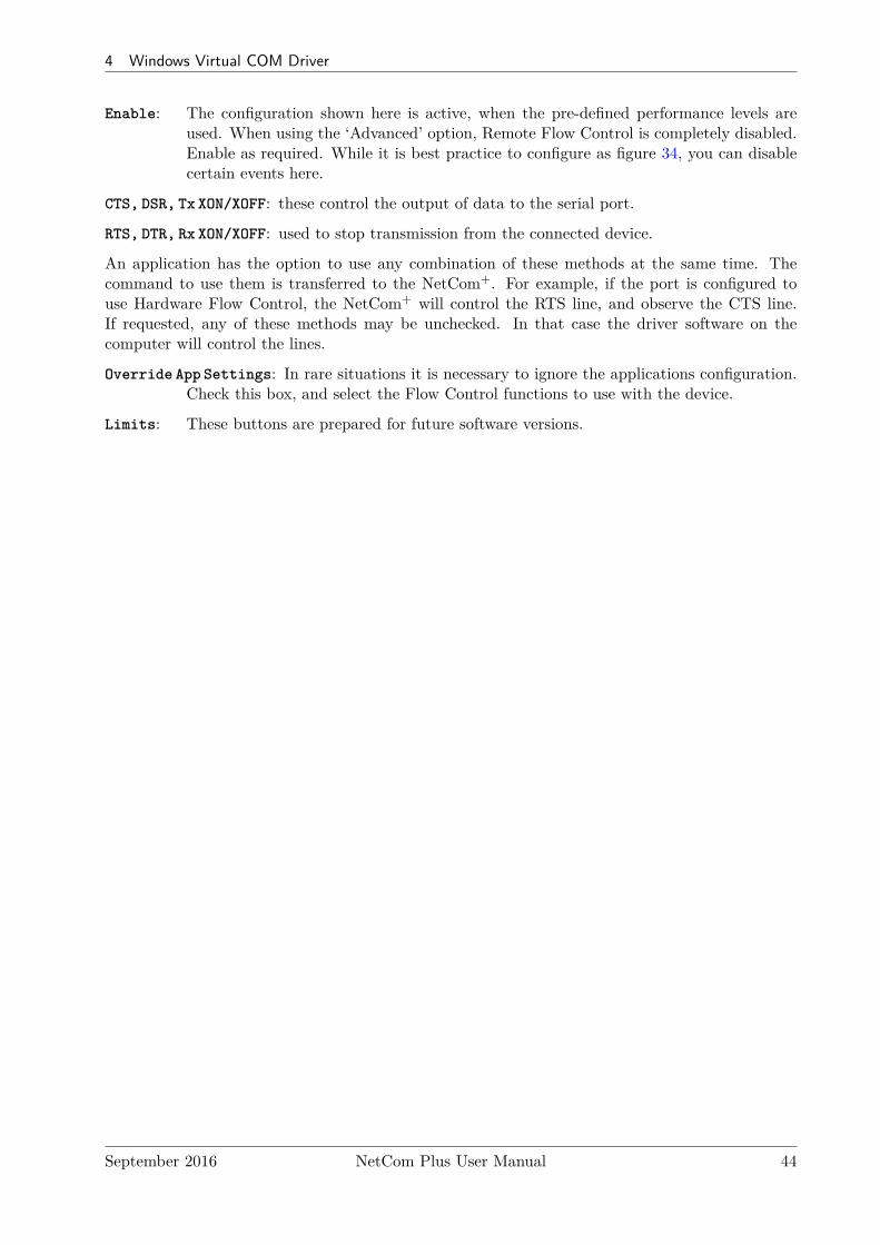
4 Windows Virtual COM Driver
Enable: The configuration shown here is active, when the pre-defined performance levels areused. When using the ‘Advanced’ option, Remote Flow Control is completely disabled.Enable as required. While it is best practice to configure as figure 34, you can disablecertain events here.
CTS, DSR, Tx XON/XOFF: these control the output of data to the serial port.
RTS, DTR, Rx XON/XOFF: used to stop transmission from the connected device.
An application has the option to use any combination of these methods at the same time. Thecommand to use them is transferred to the NetCom+. For example, if the port is configured touse Hardware Flow Control, the NetCom+ will control the RTS line, and observe the CTS line.If requested, any of these methods may be unchecked. In that case the driver software on thecomputer will control the lines.
Override App Settings: In rare situations it is necessary to ignore the applications configuration.Check this box, and select the Flow Control functions to use with the device.
Limits: These buttons are prepared for future software versions.
September 2016 NetCom Plus User Manual 44
4 Windows Virtual COM Driver
4.4.5 Installation of NetCom Plus Servers
This section of the manual covers the correct installation of the drivers and serial ports. Pleasedo a quick review of the section 4.1, before reading further. As of the time of writing, the currentdriver is version 2.0.0.0
Figure 35: Select NetCom+ to install
The NetCom Plus Manager program is automatically started by the Installation Wizard, or laterintentionally by the user (see fig. 29). There are different ways the NetCom+ servers are listed.
Figure 36: New NetCom+
The first time a NetCom+ is detected it is displayed in bluecolor. This indicates a “New” status, i.e. it is not yet installedin the system, but it is ready to. When the NetCom PlusManager is closed by the OK button the server and the serialports on it are installed in the operating system.
Figure 37: Installed NetCom+
When the NetCom Plus Manager is started a second time,usually the NetCom+ in the network are already installed inWindows. Then the icon is shown in green color. Exiting theNetCom Plus Manager by OK button will not change this partof the installation.
September 2016 NetCom Plus User Manual 45
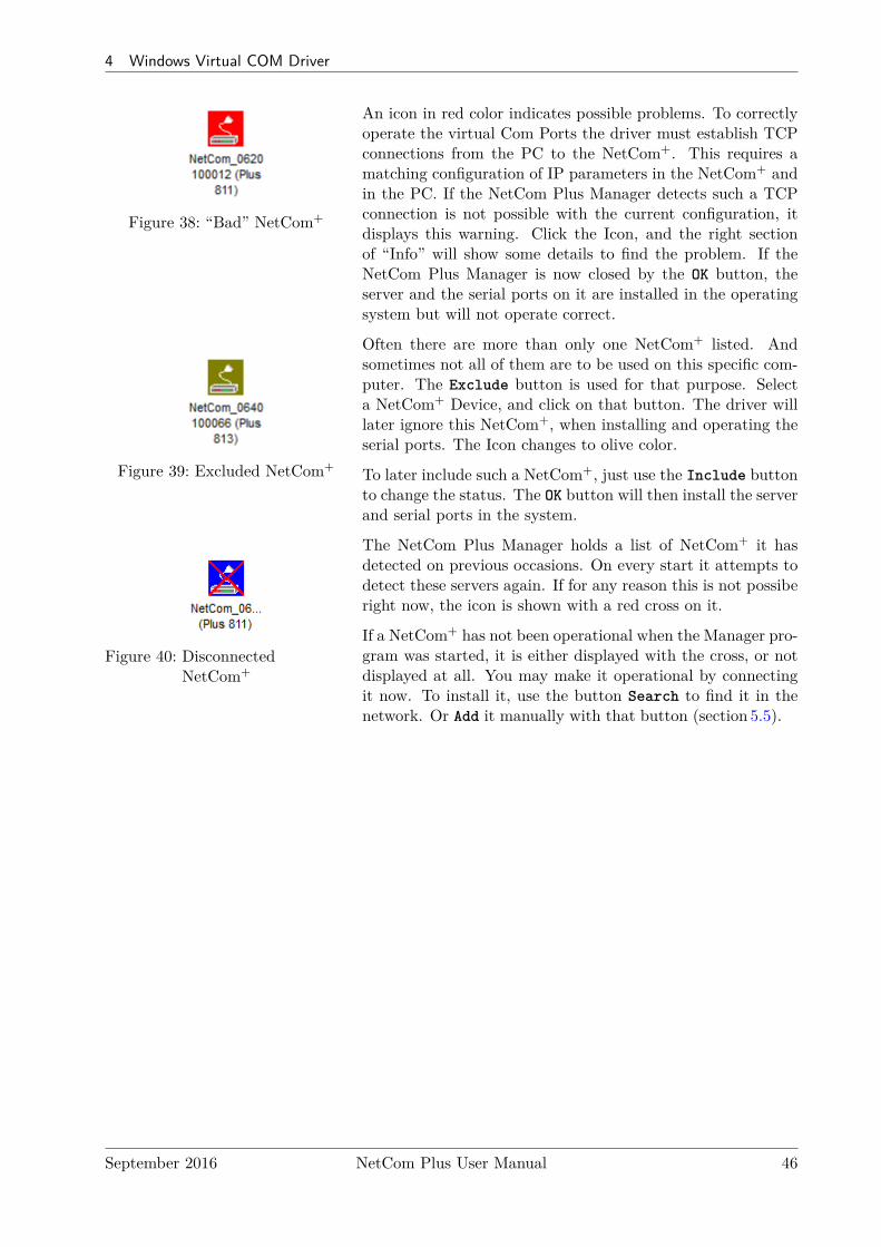
4 Windows Virtual COM Driver
Figure 38: “Bad” NetCom+
An icon in red color indicates possible problems. To correctlyoperate the virtual Com Ports the driver must establish TCPconnections from the PC to the NetCom+. This requires amatching configuration of IP parameters in the NetCom+ andin the PC. If the NetCom Plus Manager detects such a TCPconnection is not possible with the current configuration, itdisplays this warning. Click the Icon, and the right sectionof “Info” will show some details to find the problem. If theNetCom Plus Manager is now closed by the OK button, theserver and the serial ports on it are installed in the operatingsystem but will not operate correct.
Figure 39: Excluded NetCom+
Often there are more than only one NetCom+ listed. Andsometimes not all of them are to be used on this specific com-puter. The Exclude button is used for that purpose. Selecta NetCom+ Device, and click on that button. The driver willlater ignore this NetCom+, when installing and operating theserial ports. The Icon changes to olive color.
To later include such a NetCom+, just use the Include buttonto change the status. The OK button will then install the serverand serial ports in the system.
Figure 40: DisconnectedNetCom+
The NetCom Plus Manager holds a list of NetCom+ it hasdetected on previous occasions. On every start it attempts todetect these servers again. If for any reason this is not possiberight now, the icon is shown with a red cross on it.
If a NetCom+ has not been operational when the Manager pro-gram was started, it is either displayed with the cross, or notdisplayed at all. You may make it operational by connectingit now. To install it, use the button Search to find it in thenetwork. Or Add it manually with that button (section 5.5).
September 2016 NetCom Plus User Manual 46
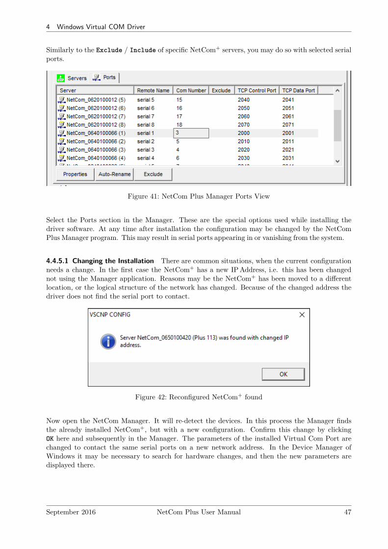
4 Windows Virtual COM Driver
Similarly to the Exclude / Include of specific NetCom+ servers, you may do so with selected serialports.
Figure 41: NetCom Plus Manager Ports View
Select the Ports section in the Manager. These are the special options used while installing thedriver software. At any time after installation the configuration may be changed by the NetComPlus Manager program. This may result in serial ports appearing in or vanishing from the system.
4.4.5.1 Changing the Installation There are common situations, when the current configurationneeds a change. In the first case the NetCom+ has a new IPAddress, i.e. this has been changednot using the Manager application. Reasons may be the NetCom+ has been moved to a differentlocation, or the logical structure of the network has changed. Because of the changed address thedriver does not find the serial port to contact.
Figure 42: Reconfigured NetCom+ found
Now open the NetCom Manager. It will re-detect the devices. In this process the Manager findsthe already installed NetCom+, but with a new configuration. Confirm this change by clickingOK here and subsequently in the Manager. The parameters of the installed Virtual Com Port arechanged to contact the same serial ports on a new network address. In the Device Manager ofWindows it may be necessary to search for hardware changes, and then the new parameters aredisplayed there.
September 2016 NetCom Plus User Manual 47

4 Windows Virtual COM Driver
Figure 43: Replaced NetCom+ found
The second case occurs, when a NetCom+ is replaced by another device. This new device shall havethe same configuration, especially the same IPAddress. When you start the NetCom Manager, itwill detect a new device with parameters already in the database. It is assumed the new deviceshall replace the old one, click on the No button to confirm. Otherwise an installation of new serialports is performed.
In general the driver software and the NetCom Manager identify the NetCom+ Devices by thecombination of IPAddress and serial number (plus MAC Address). If one of these is changed, theabove requests appear.
4.5 Uninstall the Drivers and Tools
To completely uninstall the NetCom+ Drivers and files, there are two basic methods. The usualway is to use the program uninstall option of Windows operating system. On Windows 10 openSettings and therein the SYSTEM function. Select Apps & Features, and scroll down to theVScom drivers. Select this entry and click the Uninstall option. This will start the NetCom+
uninstallation program.
Figure 44: Uninstall NetCom+ Drivers via Settings App
On Windows 7 you’ll find the function in Control Panel, Category Programs as Uninstall a pro-gram.
September 2016 NetCom Plus User Manual 48
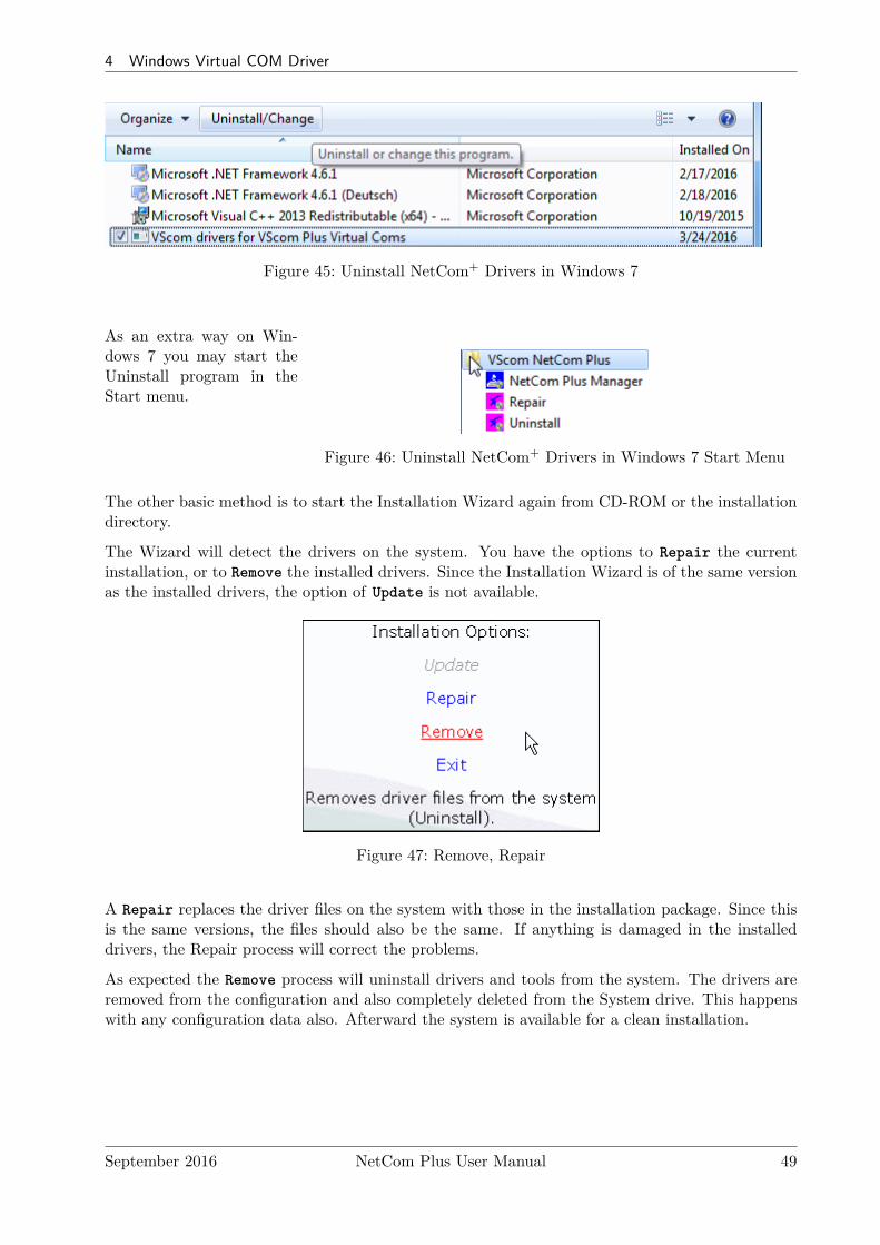
4 Windows Virtual COM Driver
Figure 45: Uninstall NetCom+ Drivers in Windows 7
Figure 46: Uninstall NetCom+ Drivers in Windows 7 Start Menu
As an extra way on Win-dows 7 you may start theUninstall program in theStart menu.
The other basic method is to start the Installation Wizard again from CD-ROM or the installationdirectory.
The Wizard will detect the drivers on the system. You have the options to Repair the currentinstallation, or to Remove the installed drivers. Since the Installation Wizard is of the same versionas the installed drivers, the option of Update is not available.
Figure 47: Remove, Repair
A Repair replaces the driver files on the system with those in the installation package. Since thisis the same versions, the files should also be the same. If anything is damaged in the installeddrivers, the Repair process will correct the problems.
As expected the Remove process will uninstall drivers and tools from the system. The drivers areremoved from the configuration and also completely deleted from the System drive. This happenswith any configuration data also. Afterward the system is available for a clean installation.
September 2016 NetCom Plus User Manual 49
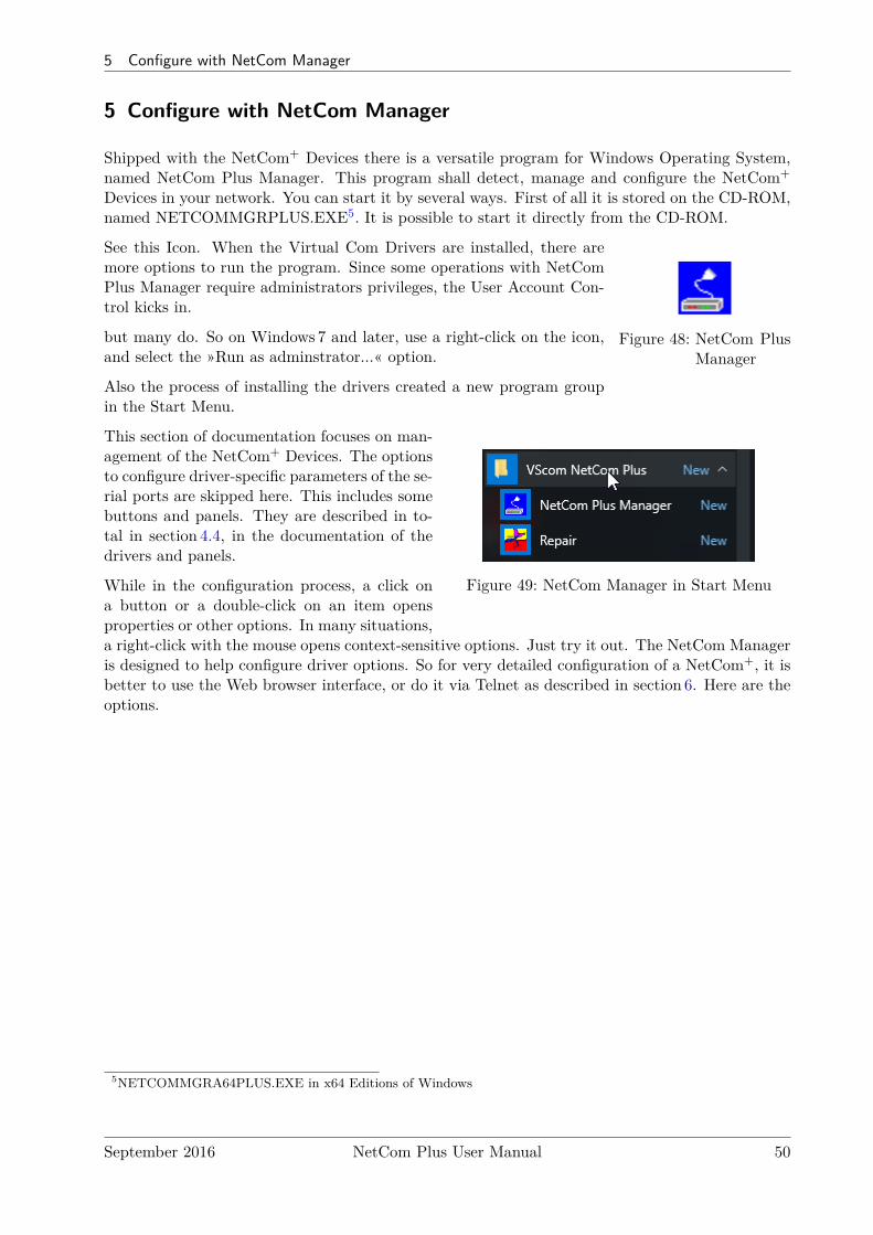
5 Configure with NetCom Manager
5 Configure with NetCom Manager
Shipped with the NetCom+ Devices there is a versatile program for Windows Operating System,named NetCom Plus Manager. This program shall detect, manage and configure the NetCom+
Devices in your network. You can start it by several ways. First of all it is stored on the CD-ROM,named NETCOMMGRPLUS.EXE5. It is possible to start it directly from the CD-ROM.
Figure 48: NetCom PlusManager
See this Icon. When the Virtual Com Drivers are installed, there aremore options to run the program. Since some operations with NetComPlus Manager require administrators privileges, the User Account Con-trol kicks in.
but many do. So on Windows 7 and later, use a right-click on the icon,and select the »Run as adminstrator...« option.
Also the process of installing the drivers created a new program groupin the Start Menu.
Figure 49: NetCom Manager in Start Menu
This section of documentation focuses on man-agement of the NetCom+ Devices. The optionsto configure driver-specific parameters of the se-rial ports are skipped here. This includes somebuttons and panels. They are described in to-tal in section 4.4, in the documentation of thedrivers and panels.
While in the configuration process, a click ona button or a double-click on an item opensproperties or other options. In many situations,a right-click with the mouse opens context-sensitive options. Just try it out. The NetCom Manageris designed to help configure driver options. So for very detailed configuration of a NetCom+, it isbetter to use the Web browser interface, or do it via Telnet as described in section 6. Here are theoptions.
5NETCOMMGRA64PLUS.EXE in x64 Editions of Windows
September 2016 NetCom Plus User Manual 50
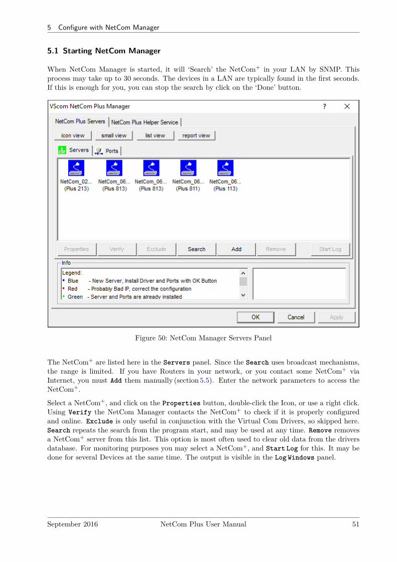
5 Configure with NetCom Manager
5.1 Starting NetCom Manager
When NetCom Manager is started, it will ‘Search’ the NetCom+ in your LAN by SNMP. Thisprocess may take up to 30 seconds. The devices in a LAN are typically found in the first seconds.If this is enough for you, you can stop the search by click on the ‘Done’ button.
Figure 50: NetCom Manager Servers Panel
The NetCom+ are listed here in the Servers panel. Since the Search uses broadcast mechanisms,the range is limited. If you have Routers in your network, or you contact some NetCom+ viaInternet, you must Add them manually (section 5.5). Enter the network parameters to access theNetCom+.
Select a NetCom+, and click on the Properties button, double-click the Icon, or use a right click.Using Verify the NetCom Manager contacts the NetCom+ to check if it is properly configuredand online. Exclude is only useful in conjunction with the Virtual Com Drivers, so skipped here.Search repeats the search from the program start, and may be used at any time. Remove removesa NetCom+ server from this list. This option is most often used to clear old data from the driversdatabase. For monitoring purposes you may select a NetCom+, and Start Log for this. It may bedone for several Devices at the same time. The output is visible in the Log Windows panel.
September 2016 NetCom Plus User Manual 51
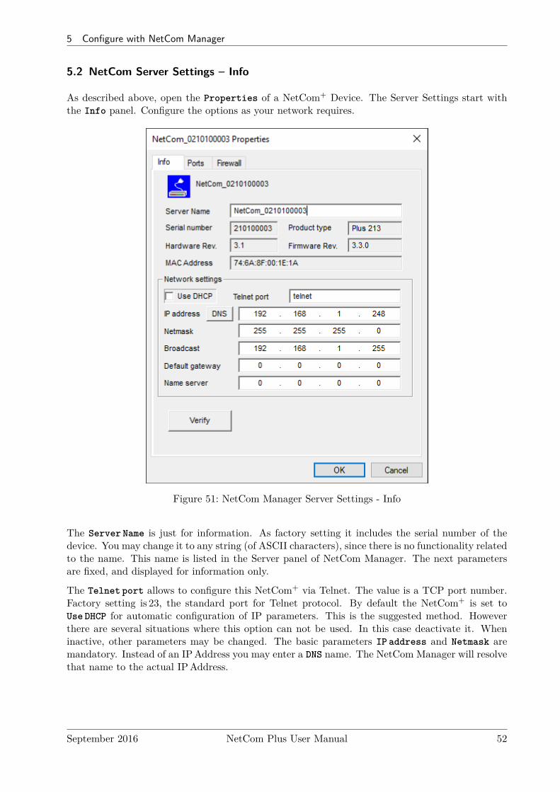
5 Configure with NetCom Manager
5.2 NetCom Server Settings – Info
As described above, open the Properties of a NetCom+ Device. The Server Settings start withthe Info panel. Configure the options as your network requires.
Figure 51: NetCom Manager Server Settings - Info
The Server Name is just for information. As factory setting it includes the serial number of thedevice. You may change it to any string (of ASCII characters), since there is no functionality relatedto the name. This name is listed in the Server panel of NetCom Manager. The next parametersare fixed, and displayed for information only.
The Telnet port allows to configure this NetCom+ via Telnet. The value is a TCP port number.Factory setting is 23, the standard port for Telnet protocol. By default the NetCom+ is set toUse DHCP for automatic configuration of IP parameters. This is the suggested method. Howeverthere are several situations where this option can not be used. In this case deactivate it. Wheninactive, other parameters may be changed. The basic parameters IP address and Netmask aremandatory. Instead of an IPAddress you may enter a DNS name. The NetCom Manager will resolvethat name to the actual IPAddress.
September 2016 NetCom Plus User Manual 52
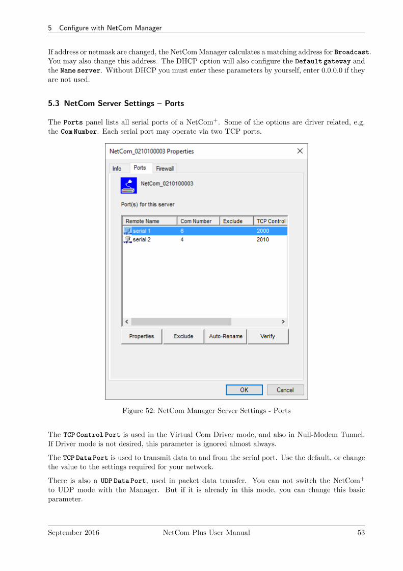
5 Configure with NetCom Manager
If address or netmask are changed, the NetComManager calculates a matching address for Broadcast.You may also change this address. The DHCP option will also configure the Default gateway andthe Name server. Without DHCP you must enter these parameters by yourself, enter 0.0.0.0 if theyare not used.
5.3 NetCom Server Settings – Ports
The Ports panel lists all serial ports of a NetCom+. Some of the options are driver related, e.g.the Com Number. Each serial port may operate via two TCP ports.
Figure 52: NetCom Manager Server Settings - Ports
The TCP Control Port is used in the Virtual Com Driver mode, and also in Null-Modem Tunnel.If Driver mode is not desired, this parameter is ignored almost always.
The TCP Data Port is used to transmit data to and from the serial port. Use the default, or changethe value to the settings required for your network.
There is also a UDP Data Port, used in packet data transfer. You can not switch the NetCom+
to UDP mode with the Manager. But if it is already in this mode, you can change this basicparameter.
September 2016 NetCom Plus User Manual 53

5 Configure with NetCom Manager
5.4 NetCom Server Settings – Firewall
Many networks use a Firewall to protect the stations in the network from other networks, includingthe Internet. In some situations the contact to a NetCom+ must pass through such a Firewallconfigured for NAT (Network Address Translation, section 15).
Figure 53: NetCom Manager Server Settings - Firewall
To do this you must Enable Firewall, and enter the Address of the Firewall. The address maybe the IPAddress, or the Qualified Domain Name (DNS).
The Manager configures a NetCom+ via SNMP, which uses UDP. The Firewall must have a specialPort to receive those data, and to transfer it to the internal network. Enter this port here.
The same scheme applies to the logging option. When logging is active a NetCom+ listens onport 1200 for logging connections. The Firewall must also have a special Log Port to receive thisconnection, and to transfer it to the NetCom+.
The NetCom+ does not need any configuration to operate in a Firewall protected environment.This configuration here is for installation of the drivers. There is a Firewall tutorial section laterin this manual (5.6).
September 2016 NetCom Plus User Manual 54
5 Configure with NetCom Manager
5.5 Manual Detection/Installation of a NetCom
Sometimes the NetCom+ Device Server can not be detected by the automatic in the NetComManager. To detect and configure devices the protocol SNMP is used. The detection is doneby sending out a broadcast on all available network interfaces of your computer. This SNMPbroadcast is realized as an Ethernet broadcast. Such a broadcast is only transmitted throughHubs and Switches. When there is a Router between the computer and the NetCom+, probablythe broadcast is not transmitted further. This is especially the situation when the NetCom+ islocated somewhere via Internet, but also in big networks of some companies. If this is the case, thedetection has to be done manually. Refer to figure 35 and Add the NetCom+ by use of the button.Enter the IPAddress of the NetCom+ in the NetCom Manager Server Settings, and click the buttonVerify. Since now the IPAddress of the NetCom+ is known, the NetCom Manager sends a requestdirectly to this target, instead of a broadcast. This directed SNMP request is transported, evenby Routers. The NetCom+ sends the normal reply, giving all required information to the NetComManager. Now it is possible to configure all options as usual. Also the drivers for virtual serialports are installable now.
Please note, the drivers require to have the IPAddress. They can not operate using a DNS name,because the driver can not perform a DNS name resolution. If your NetCom+ is located on adynamic IPAddress (e.g. on a Dial-Up connection with 24 hours disconnection), you need toreconfigure the driver installation, when the IPAddress has changed.
5.6 Firewall Traversal Configuration
There are more difficult situations with a Firewall between the NetCom+ and the NetCom Man-ager. Many Firewalls protect the internal LAN by using the feature of NAT (Network AddressTranslation, 15). In this situation the IPAddress of the internal device is not visible on the In-ternet. Only the Firewall can be contacted via its public IPAddress. The NetCom Manager andthe driver software for the virtual serial ports can handle such setups. But this requires certainconfigurations.
An easy-to-use alternative is the VPN function, which makes Firewall configuration quite easy.
5.6.1 SOHO Firewall example
The most easy situation for such a setup is by using a very simple SOHO Router as the Fire-wall. This configuration will show the principle of the technical details. Those principles can betransferred very easy to the configuration of more complicated installations.
On the SOHO Router there is only one public IPAddress on the external side, and typically 254internal private IPAddresses for the LAN side. These internal addresses may be assigned by DHCPor static. Such Routers offer a feature typically named "DMZ", which in fact is only a single exposedhost. It is recommended not to use the "DMZ" for several reasons, some of them are security related.Especially it is recommended not to configure a NetCom+ as the DMZ host.
September 2016 NetCom Plus User Manual 55
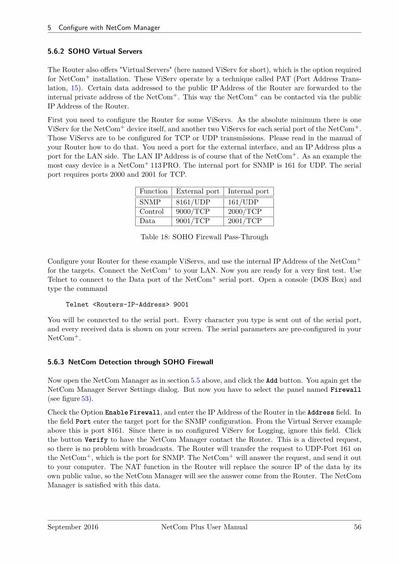
5 Configure with NetCom Manager
5.6.2 SOHO Virtual Servers
The Router also offers "Virtual Servers" (here named ViServ for short), which is the option requiredfor NetCom+ installation. These ViServ operate by a technique called PAT (Port Address Trans-lation, 15). Certain data addressed to the public IPAddress of the Router are forwarded to theinternal private address of the NetCom+. This way the NetCom+ can be contacted via the publicIPAddress of the Router.
First you need to configure the Router for some ViServs. As the absolute minimum there is oneViServ for the NetCom+ device itself, and another two ViServs for each serial port of the NetCom+.Those ViServs are to be configured for TCP or UDP transmissions. Please read in the manual ofyour Router how to do that. You need a port for the external interface, and an IPAddress plus aport for the LAN side. The LAN IPAddress is of course that of the NetCom+. As an example themost easy device is a NetCom+ 113PRO. The internal port for SNMP is 161 for UDP. The serialport requires ports 2000 and 2001 for TCP.
Function External port Internal portSNMP 8161/UDP 161/UDPControl 9000/TCP 2000/TCPData 9001/TCP 2001/TCP
Table 18: SOHO Firewall Pass-Through
Configure your Router for these example ViServs, and use the internal IPAddress of the NetCom+
for the targets. Connect the NetCom+ to your LAN. Now you are ready for a very first test. UseTelnet to connect to the Data port of the NetCom+ serial port. Open a console (DOS Box) andtype the command
Telnet <Routers-IP-Address> 9001
You will be connected to the serial port. Every character you type is sent out of the serial port,and every received data is shown on your screen. The serial parameters are pre-configured in yourNetCom+.
5.6.3 NetCom Detection through SOHO Firewall
Now open the NetCom Manager as in section 5.5 above, and click the Add button. You again get theNetCom Manager Server Settings dialog. But now you have to select the panel named Firewall(see figure 53).
Check the Option Enable Firewall, and enter the IPAddress of the Router in the Address field. Inthe field Port enter the target port for the SNMP configuration. From the Virtual Server exampleabove this is port 8161. Since there is no configured ViServ for Logging, ignore this field. Clickthe button Verify to have the NetCom Manager contact the Router. This is a directed request,so there is no problem with broadcasts. The Router will transfer the request to UDP-Port 161 onthe NetCom+, which is the port for SNMP. The NetCom+ will answer the request, and send it outto your computer. The NAT function in the Router will replace the source IP of the data by itsown public value, so the NetCom Manager will see the answer come from the Router. The NetComManager is satisfied with this data.
September 2016 NetCom Plus User Manual 56

5 Configure with NetCom Manager
Some ISP will block the SNMP protocol, which typically means they do not transport data for161/udp to their customers (this is the first reason why port 8161 was used in the example).
This answer brings every required information about the NetCom+, including its internal IPAddress.Select the panel of NetCom Manager Server Settings to verify the information, but do not makeany changes here. Changing the configuration may disconnect the NetCom+ from the protectedLAN.
5.6.4 Serial Ports through SOHO Firewall
Now the NetCom+ is available in the NetCom Manager, but still the serial ports are not usable.The information of the TCP-ports for the ViServ related to the serial port is still missing. In theNetCom Manager Server Settings select the NetCom Manager Ports Panel. In this panel select oneserial port, in this example of NetCom Plus 111 there is only one serial port. Click the Propertiesbutton to open the configuration of the port.
Figure 54: NetCom Manager Port Configuration for Driver
Since the Firewall function is enabled, the parameters for Firewall mapping are available forediting. Enter the ports defined in the Router, 9001 and 9000 in this example. Please note, sofar there is no number for the Virtual Com Port available. The driver is not installed in thismoment, and Windows does not know about the available hardware. This will happen later in theinstallation. Click the OK button, and proceed with the driver installation as already described.
September 2016 NetCom Plus User Manual 57
5 Configure with NetCom Manager
5.6.5 DMZ and Virtual Servers
Why is it recommended not to use the DMZ function of the Router? There are two reasons. Thefirst one is simple, only one device in the LAN can be defined as the DMZ target. The DMZ isimplemented as "Send all IP data targeted for the Router to the DMZ station, unless there is aspecific rule for a different target". When a second NetCom+ shall be installed on the LAN, theVirtual Servers have to be configured anyway.
The second reason is the security. Using the “DMZ” option the Firewall in the Router becomestransparent. All data from outside is transferred to the LAN, including all malicious data. Ingeneral this is not an especially smart idea.
5.6.6 Firewalls in Foreign Networks
There are many situations where it is not possible to configure the firewall between the Internetand the network where NetCom+ is installed. For example this may be a company network, whereit is not allowed to open the firewall for external access to internal stations. Or it may be part ofa GSM network, where the provider uses private IPAddresses to connect customers equipment.
Given such a configuration the NetCom+ has access to the Internet by establishing the connectionson its own. This restricts the operation modes of the serial ports (see 6.2.2.2 on page 76) to“TCP Raw Client” and “IP Modem”, where the NetCom+ operates as a client. Here the NetCom+
establishes a connection to an external server, which is out-going from the network of installation.The user has to provide the external server, accessible via the Internet.
Another way to work around the restrictions is the encrypted VPN (chapter 10 on page 111). Alsohere the user provides a server to manage the OpenVPN connections, and the users PC connects tothis server. Once this is established there is the independent and not filtered network of the VPN,where all operation modes of the NetCom+ are available without limitations.
5.7 Dynamic IP Address and OpenVPN™
The option of Encryption uses a Virtual Private Network (VPN) based on a single TCP connectionbetween the NetCom+ and a client computer. Regardless of strong encryption or even no encryptionat all, here the key point is the single TCP connection. It is more simple to provide a Firewallconfiguration for a single connection, so the Router Firewall is more easy to set up.
The network link established by OpenVPN™ requires to have a target address and a port number.Since the basic TCP connection is activated by the openvpn.exe program, there is the freedom ofusing a DNS name for the target device.
With a Dynamic IPAddress for the NetCom+ site, one of the several Internet services for DynamicDNS (DynDNS) may help. It is even relatively simple to construct an own version. Using thisservice the openvpn.exe program gets the IPAddress of the Firewall Router, and will establish thelink. When the IPAddress changes (after 24 hours), the connection first gets lost. OpenVPN™will continuously attempt to connect again. When the new IPAddress is known via DynDNS,the network link is re-established. The NetCom+ is available again, because the IPAddress onthe OpenVPN™ link did not change. Even when a serial port has been open, the function maycontinue seamlessly.
September 2016 NetCom Plus User Manual 58
6 Configure the Operation Modes
6 Configure the Operation Modes
The NetCom+ Devices are often used without the installation of a driver software. Customerapplications contact the NetCom+ directly, using network functions. These setups require inde-pendent configuration of the NetCom+ Device and the serial ports. There are four ways to dothis configuration. The NetCom+ offers a Web browser interface, configuration via serial port, viaTelnet and also via SNMP. This SNMP option is not covered in this manual, please see separatedocumentation. The NetCom Manager program for Windows is already explained above.
The access to the NetCom+ via web interface or Telnet are done via a TCP/IP connection betweenthe computer and the NetCom+. So users need the IPAddress of the NetCom+. The most easyway to retrieve this information is the NetCom Manager program (section 5). Start it, and openthe Info Panel (figure 51) of the NetCom+ Server you want to configure. This panel displays thecurrent IPAddress of the NetCom+. Do not change the parameters, just write down the value.
The default configuration of a NetCom+ is for use of a DHCP server. When such is not available,the IPAddress defaults to 192.168.254.254. When the IPAddress of the NetCom+ is not in finalstate, leave the NetCom Manager open while doing the first configuration of the NetCom+ Server.But in general the software may be closed as soon as the IPAddress is known.
6.1 Accessing the Configurations
Here the manual shortly explains the different methods to get access on the parameters of aNetCom+. These parameters are the same, independent from the method for configuration. So theoptions are described later.
The configuration is accessible via web browser, a Telnet software with VT100/VT52 emulation,or via a Terminal emulation connected to the first serial port of the NetCom+ .
6.1.1 Web Browser Configuration
Open your favorite web browser, and enter the IPAddress as the target location. To avoid anyconfusion you should precede it with http://, so your browser has definite target information. Mostbrowser programs do not need that. Your browser must not suppress images.
If the NetCom+ is password protected, you must enter this now. Leave the user name empty, justtype the password.
September 2016 NetCom Plus User Manual 59
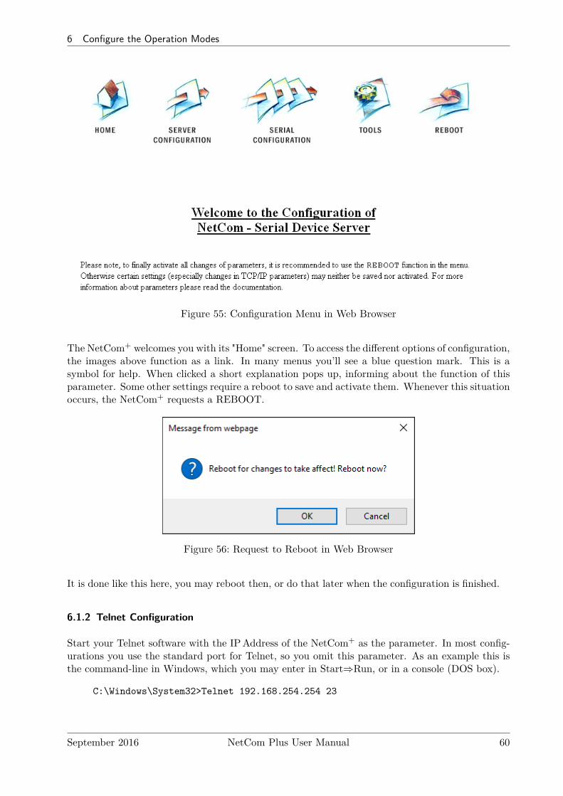
6 Configure the Operation Modes
Figure 55: Configuration Menu in Web Browser
The NetCom+ welcomes you with its "Home" screen. To access the different options of configuration,the images above function as a link. In many menus you’ll see a blue question mark. This is asymbol for help. When clicked a short explanation pops up, informing about the function of thisparameter. Some other settings require a reboot to save and activate them. Whenever this situationoccurs, the NetCom+ requests a REBOOT.
Figure 56: Request to Reboot in Web Browser
It is done like this here, you may reboot then, or do that later when the configuration is finished.
6.1.2 Telnet Configuration
Start your Telnet software with the IPAddress of the NetCom+ as the parameter. In most config-urations you use the standard port for Telnet, so you omit this parameter. As an example this isthe command-line in Windows, which you may enter in Start⇒Run, or in a console (DOS box).
C:\Windows\System32>Telnet 192.168.254.254 23
September 2016 NetCom Plus User Manual 60
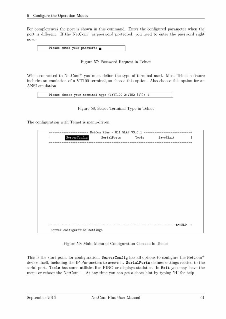
6 Configure the Operation Modes
For completeness the port is shown in this command. Enter the configured parameter when theport is different. If the NetCom+ is password protected, you need to enter the password rightnow.
Please enter your password:
Figure 57: Password Request in Telnet
When connected to NetCom+ you must define the type of terminal used. Most Telnet softwareincludes an emulation of a VT100 terminal, so choose this option. Also choose this option for anANSI emulation.
Please choose your terminal type (1:VT100 2:VT52 [1]): 1
Figure 58: Select Terminal Type in Telnet
The configuration with Telnet is menu-driven.
+--------------------- NetCom Plus - 811 WLAN V3.0.1 --------------------------+
| ServerConfig SerialPorts Tools Save&Exit |
+------------------------------------------------------------------------------+
+--------------------------------------------------------------------- h=HELP -+
Server configuration settings
Figure 59: Main Menu of Configuration Console in Telnet
This is the start point for configuration. ServerConfig has all options to configure the NetCom+
device itself, including the IP-Parameters to access it. SerialPorts defines settings related to theserial port. Tools has some utilities like PING or displays statistics. In Exit you may leave themenu or reboot the NetCom+ . At any time you can get a short hint by typing "H" for help.
September 2016 NetCom Plus User Manual 61
6 Configure the Operation Modes
Use the cursor keys to select the parameter you want to change. Hit <Enter> to edit them. Typethe new value, or select provided options. Use <Esc> to leave a parameter or menu. Please checkthe configuration of your Telnet, if there are any problems.
6.1.3 Serial Configuration
In some situations it may be impossible to get network access to the NetCom+ Device. If this hap-pens (e.g. by an accidentally misconfiguration), neither Telnet, nor the web interface is functional.It may be even impossible to use the NetCom+ Manager program.
In this case you must connect to the NetCom+ via the serial port. Disconnect any serial cable fromNetCom+. Set the DIPSwitches to "RS 232Configuration" (all switches to Off, section 3.1). Thenconnect the NetCom+ with your computer using a Null Modem cable. If your NetCom+ is an oldmodel with a connector DB9 female, attach the supplied Null-Modem Adapter to the port first. Orconnect your computer to the female connector with a straight-through cable.
Open any serial terminal program (HyperTerminal, minicom, PuTTY6, . . . ), select 38400 bps,8 Bit, No Parity as configuration. Set your terminal to emulate a VT100 (recommended, but VT52is also possible), including the Arrow keys.
Then power on the NetCom+. When connected to NetCom+ you must define the type of terminalused (VT100 or VT52), and optionally provide the password. This is the same configuration optionas described above at 6.1.2, so follow the instructions for Telnet.
When the configuration is done, change the DIPSwitches back to normal operation. Later con-figurations can be done by web interface or Telnet. Of course this requires to have a functionalIP configuration defined.
6.2 NetCom Configuration Options
Some of the menus are very long, especially on the web interface. These are divided in theirlogical sections throughout this document. Each section shortly mentions the way to access theparameters. Short screen shots show the typical display when configuring the NetCom+. Usuallythe web interface is shown on top, and the terminal interface (Telnet, serial port) is shown below;a horizontal line divides the two. On few occasions the two screen shots are displayed side by side,with the web interface to the left and the terminal interface to the right; then divided by a verticalbar.
6.2.1 Server Configuration
In your web browser click on the Icon of “SERVER CONFIGURATION”, the browser opens thebasic server information, the server parameters related to the IP-configuration, the parameters forWireless communication, the section for encrypted communication, Password settings, and finallythe configuration for date and time.
In Telnet the ServerConfig offers the IP parameters, Wireless and encrypted configuration, Pass-word settings, configuration for date and time, as well as basic server information.
6Download PuTTY from putty.org
September 2016 NetCom Plus User Manual 62

6 Configure the Operation Modes
6.2.1.1 Server InfoWeb: menu “SERVER CONFIGURATION”, section “Server Info”.Telnet: “ServerConfig”, option “Info”
ServerConfig+--------------------+| Parameter || Wireless || OpenVPN || Modbus GPIO || Authentification || Date & Time || Info |
+--------------------+
Server Info
Server Type Plus 113Software Version 3.3.1Hardware Version 3.1Serial Nr. 0650100420
UpTime 0 day(s) 00:00:40
Contact [<unset> ]
Location [<unset> ]
Figure 60: Server Information
Information about the selected NetCom+ is displayed as “Server Info”. Starting with the Server Type,this is the model of the NetCom+ , followed by the Software Version and Hardware Version. Thiswill give a rough overview, which features are implemented, or need an upgrade of the firmware.The Serial Nr. is important to identify the device you are configuring right now. For furtherinformation the UpTime is listed.
Contact and Location are user-defined information. They may later help to find the device in theinstallation, and the person responsible for management. The Administrator may provide somecontact information here.Contact defines a person to contact for help, e.g. "Mrs. Jane Doe, 555-HELP". Location isthe physical place of the NetCom+, e.g. "CeBIT Hall 12, Service Box IX.a". These data arerestricted to ASCII characters.
6.2.1.2 Server ParameterWeb: menu “SERVER CONFIGURATION”, section “Server Parameter”.Telnet: “ServerConfig”, option “Parameter”
The Server Parameter allow configuration of the NetCom+s name and of course all parameters inIP-settings. The Server Name is used as general information, e.g. in the NetCom Manager program.On a NetCom Plus with WLAN option you may choose the network Interface Priority as Cable,Wireless or both (priority Cable,Wireless or Wireless,Cable).
September 2016 NetCom Plus User Manual 63
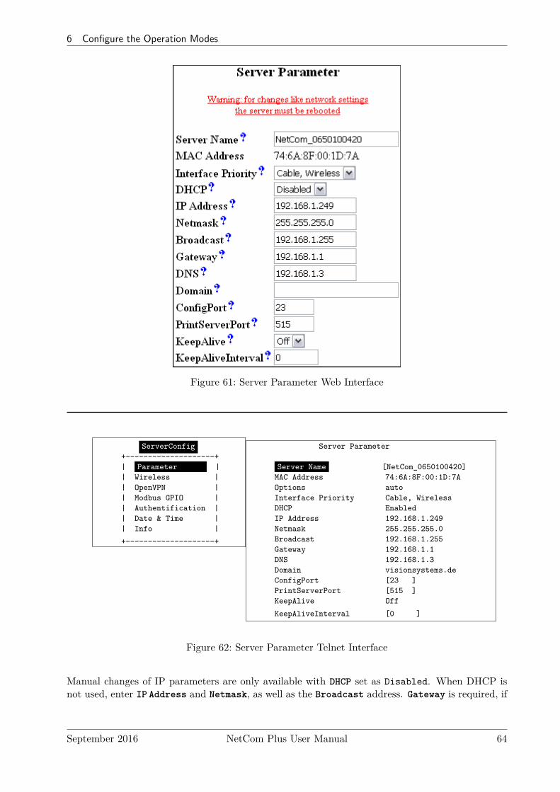
6 Configure the Operation Modes
Figure 61: Server Parameter Web Interface
ServerConfig+--------------------+| Parameter || Wireless || OpenVPN || Modbus GPIO || Authentification || Date & Time || Info |
+--------------------+
Server Parameter
Server Name [NetCom_0650100420]MAC Address 74:6A:8F:00:1D:7AOptions autoInterface Priority Cable, WirelessDHCP EnabledIP Address 192.168.1.249Netmask 255.255.255.0Broadcast 192.168.1.255Gateway 192.168.1.1DNS 192.168.1.3Domain visionsystems.deConfigPort [23 ]PrintServerPort [515 ]KeepAlive Off
KeepAliveInterval [0 ]
Figure 62: Server Parameter Telnet Interface
Manual changes of IP parameters are only available with DHCP set as Disabled. When DHCP isnot used, enter IP Address and Netmask, as well as the Broadcast address. Gateway is required, if
September 2016 NetCom Plus User Manual 64
6 Configure the Operation Modes
there are Routers in the network. DNS is used to access other stations by name. The ConfigPortis used to access the NetCom+ for administration via Telnet. It is suggested to use the standardvalue for Telnet, TCP port number 23. However it may be changed for different purposes. Thisdoes not change the function of the Telnet menus.
The firmware can operate each serial port as Print Server. The TCP Port defined by RFC1194(mostly referred to as »Line Printer Daemon«) is 515, under certain circumstances you may changethe PrintServerPort. More about Print Server function at the configuration of the serial ports( 6.2.2.2.8 on page 85).
KeepAlive is an intrinsic function of the TCP/IP protocol. If used it causes network traffic,traditionally intended to prohibit automatic shut-down of Dial-Up network equipment. In a LANthis traffic usually is not a problem. If this functions is On, you must define a KeepAliveIntervalgiven in seconds. As a side effect of the traffic network problems are detected earlier. NetCom+
has a better chance to react on network problems, or failed hosts. Even dropping an old connectionmay be useful in certain environments. It is suggested to activate this function when using RAWTCP communication (6.2.2.2.2, 6.2.2.2.3), with an interval of about 180 seconds.
September 2016 NetCom Plus User Manual 65
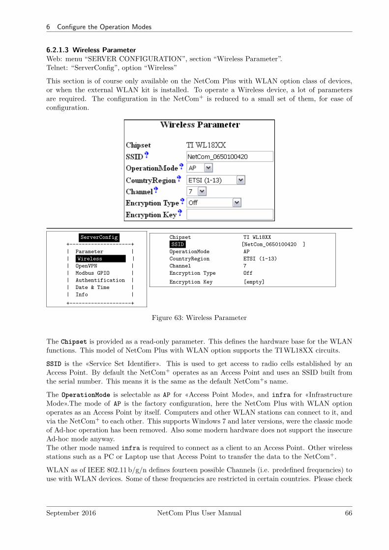
6 Configure the Operation Modes
6.2.1.3 Wireless ParameterWeb: menu “SERVER CONFIGURATION”, section “Wireless Parameter”.Telnet: “ServerConfig”, option “Wireless”
This section is of course only available on the NetCom Plus with WLAN option class of devices,or when the external WLAN kit is installed. To operate a Wireless device, a lot of parametersare required. The configuration in the NetCom+ is reduced to a small set of them, for ease ofconfiguration.
ServerConfig+--------------------+| Parameter || Wireless || OpenVPN || Modbus GPIO || Authentification || Date & Time || Info |
+--------------------+
Chipset TI WL18XXSSID [NetCom_0650100420 ]
OperationMode APCountryRegion ETSI (1-13)Channel 7Encryption Type Off
Encryption Key [empty]
Figure 63: Wireless Parameter
The Chipset is provided as a read-only parameter. This defines the hardware base for the WLANfunctions. This model of NetCom Plus with WLAN option supports the TIWL18XX circuits.
SSID is the «Service Set Identifier». This is used to get access to radio cells established by anAccess Point. By default the NetCom+ operates as an Access Point and uses an SSID built fromthe serial number. This means it is the same as the default NetCom+s name.
The OperationMode is selectable as AP for «Access Point Mode», and infra for «InfrastructureMode».The mode of AP is the factory configuration, here the NetCom Plus with WLAN optionoperates as an Access Point by itself. Computers and other WLAN stations can connect to it, andvia the NetCom+ to each other. This supports Windows 7 and later versions, were the classic modeof Ad-hoc operation has been removed. Also some modern hardware does not support the insecureAd-hoc mode anyway.The other mode named infra is required to connect as a client to an Access Point. Other wirelessstations such as a PC or Laptop use that Access Point to transfer the data to the NetCom+.
WLAN as of IEEE 802.11 b/g/n defines fourteen possible Channels (i.e. predefined frequencies) touse with WLAN devices. Some of these frequencies are restricted in certain countries. Please check
September 2016 NetCom Plus User Manual 66
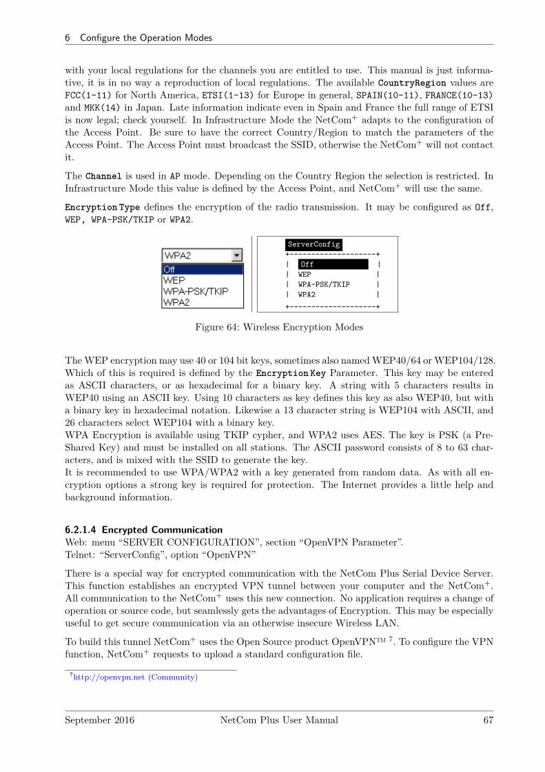
6 Configure the Operation Modes
with your local regulations for the channels you are entitled to use. This manual is just informa-tive, it is in no way a reproduction of local regulations. The available CountryRegion values areFCC(1-11) for North America, ETSI(1-13) for Europe in general, SPAIN(10-11), FRANCE(10-13)and MKK(14) in Japan. Late information indicate even in Spain and France the full range of ETSIis now legal; check yourself. In Infrastructure Mode the NetCom+ adapts to the configuration ofthe Access Point. Be sure to have the correct Country/Region to match the parameters of theAccess Point. The Access Point must broadcast the SSID, otherwise the NetCom+ will not contactit.
The Channel is used in AP mode. Depending on the Country Region the selection is restricted. InInfrastructure Mode this value is defined by the Access Point, and NetCom+ will use the same.
Encryption Type defines the encryption of the radio transmission. It may be configured as Off,WEP, WPA-PSK/TKIP or WPA2.
ServerConfig+--------------------+| Off || WEP || WPA-PSK/TKIP || WPA2 |
+--------------------+
Figure 64: Wireless Encryption Modes
TheWEP encryption may use 40 or 104 bit keys, sometimes also namedWEP40/64 or WEP104/128.Which of this is required is defined by the Encryption Key Parameter. This key may be enteredas ASCII characters, or as hexadecimal for a binary key. A string with 5 characters results inWEP40 using an ASCII key. Using 10 characters as key defines this key as also WEP40, but witha binary key in hexadecimal notation. Likewise a 13 character string is WEP104 with ASCII, and26 characters select WEP104 with a binary key.WPA Encryption is available using TKIP cypher, and WPA2 uses AES. The key is PSK (a Pre-Shared Key) and must be installed on all stations. The ASCII password consists of 8 to 63 char-acters, and is mixed with the SSID to generate the key.It is recommended to use WPA/WPA2 with a key generated from random data. As with all en-cryption options a strong key is required for protection. The Internet provides a little help andbackground information.
6.2.1.4 Encrypted CommunicationWeb: menu “SERVER CONFIGURATION”, section “OpenVPN Parameter”.Telnet: “ServerConfig”, option “OpenVPN”
There is a special way for encrypted communication with the NetCom Plus Serial Device Server.This function establishes an encrypted VPN tunnel between your computer and the NetCom+.All communication to the NetCom+ uses this new connection. No application requires a change ofoperation or source code, but seamlessly gets the advantages of Encryption. This may be especiallyuseful to get secure communication via an otherwise insecure Wireless LAN.
To build this tunnel NetCom+ uses the Open Source product OpenVPN™ 7. To configure the VPNfunction, NetCom+ requests to upload a standard configuration file.
7http://openvpn.net (Community)
September 2016 NetCom Plus User Manual 67
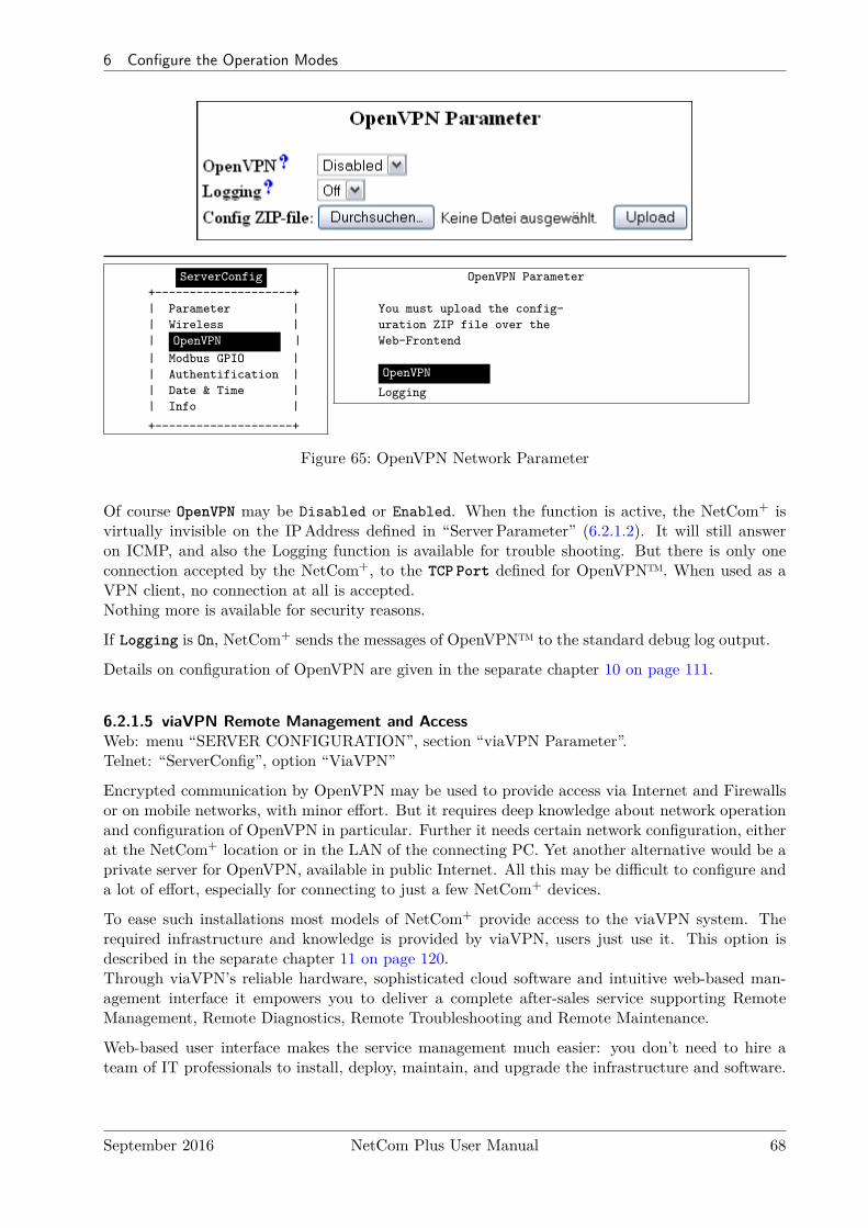
6 Configure the Operation Modes
ServerConfig+--------------------+| Parameter || Wireless || OpenVPN || Modbus GPIO || Authentification || Date & Time || Info |
+--------------------+
OpenVPN Parameter
You must upload the config-uration ZIP file over theWeb-Frontend
OpenVPN
Logging
Figure 65: OpenVPN Network Parameter
Of course OpenVPN may be Disabled or Enabled. When the function is active, the NetCom+ isvirtually invisible on the IPAddress defined in “ServerParameter” (6.2.1.2). It will still answeron ICMP, and also the Logging function is available for trouble shooting. But there is only oneconnection accepted by the NetCom+, to the TCP Port defined for OpenVPN™. When used as aVPN client, no connection at all is accepted.Nothing more is available for security reasons.
If Logging is On, NetCom+ sends the messages of OpenVPN™ to the standard debug log output.
Details on configuration of OpenVPN are given in the separate chapter 10 on page 111.
6.2.1.5 viaVPN Remote Management and AccessWeb: menu “SERVER CONFIGURATION”, section “viaVPN Parameter”.Telnet: “ServerConfig”, option “ViaVPN”
Encrypted communication by OpenVPN may be used to provide access via Internet and Firewallsor on mobile networks, with minor effort. But it requires deep knowledge about network operationand configuration of OpenVPN in particular. Further it needs certain network configuration, eitherat the NetCom+ location or in the LAN of the connecting PC. Yet another alternative would be aprivate server for OpenVPN, available in public Internet. All this may be difficult to configure anda lot of effort, especially for connecting to just a few NetCom+ devices.
To ease such installations most models of NetCom+ provide access to the viaVPN system. Therequired infrastructure and knowledge is provided by viaVPN, users just use it. This option isdescribed in the separate chapter 11 on page 120.Through viaVPN’s reliable hardware, sophisticated cloud software and intuitive web-based man-agement interface it empowers you to deliver a complete after-sales service supporting RemoteManagement, Remote Diagnostics, Remote Troubleshooting and Remote Maintenance.
Web-based user interface makes the service management much easier: you don’t need to hire ateam of IT professionals to install, deploy, maintain, and upgrade the infrastructure and software.
September 2016 NetCom Plus User Manual 68
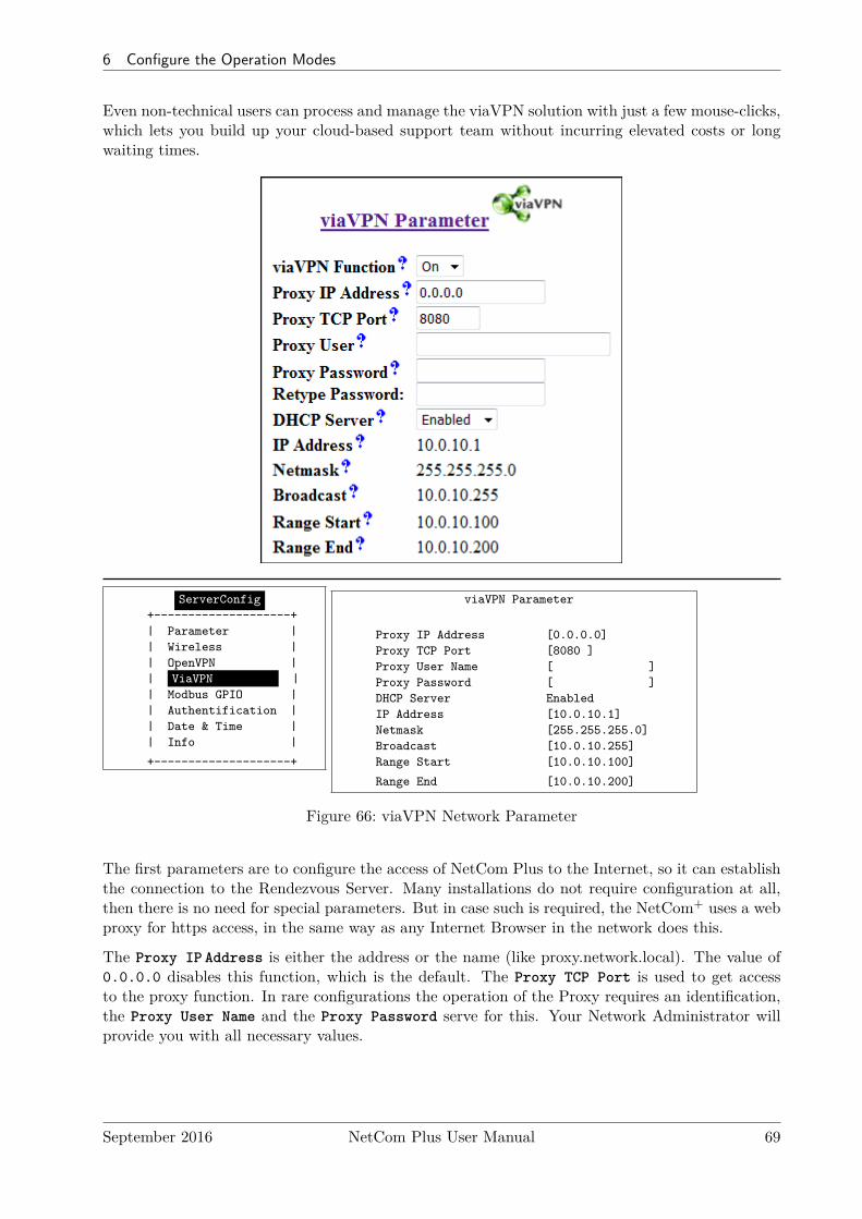
6 Configure the Operation Modes
Even non-technical users can process and manage the viaVPN solution with just a few mouse-clicks,which lets you build up your cloud-based support team without incurring elevated costs or longwaiting times.
ServerConfig+--------------------+| Parameter || Wireless || OpenVPN || ViaVPN || Modbus GPIO || Authentification || Date & Time || Info |
+--------------------+
viaVPN Parameter
Proxy IP Address [0.0.0.0]Proxy TCP Port [8080 ]Proxy User Name [ ]Proxy Password [ ]DHCP Server EnabledIP Address [10.0.10.1]Netmask [255.255.255.0]Broadcast [10.0.10.255]Range Start [10.0.10.100]
Range End [10.0.10.200]
Figure 66: viaVPN Network Parameter
The first parameters are to configure the access of NetCom Plus to the Internet, so it can establishthe connection to the Rendezvous Server. Many installations do not require configuration at all,then there is no need for special parameters. But in case such is required, the NetCom+ uses a webproxy for https access, in the same way as any Internet Browser in the network does this.
The Proxy IP Address is either the address or the name (like proxy.network.local). The value of0.0.0.0 disables this function, which is the default. The Proxy TCP Port is used to get accessto the proxy function. In rare configurations the operation of the Proxy requires an identification,the Proxy User Name and the Proxy Password serve for this. Your Network Administrator willprovide you with all necessary values.
September 2016 NetCom Plus User Manual 69

6 Configure the Operation Modes
For easy administration of connections via the PC Client Utility the NetCom Plus provides a DHCPServer. This will assign a valid configuration to the Client Utility connection to the viaVPN system.As the result the Client PC can connect to the NetCom+, and perform management operations.The following parameters configure the operation of the DHCP Server.Important Note: These parameters here do not influence the configuration in the local network(LAN). They are effective only on the connection established by the Client Utility.
The DHCP Server may be Disabled. But Enabled is the default and strongly recommended.IP Address, Netmask and Broadcast are properties of the NetCom+ side of the viaVPN con-nection. They behave in the same way as the parameters in the Server Configuration, see para-graph 6.2.1.2 on page 63. Range Start and Range End are the first (lowest) and last (highest)value the DHCP Server will assign to the Client PC side of the viaVPN connection.
6.2.1.6 Modbus GPIOThis function is only available on the NetCom Plus 811 DIO device server. The signals are controlledvia Ethernet/Internet using Modbus/TCP. This protocol has TCP port 502 defined as standardfor operation, but it may be changed to a different value if the network configuration requires this.The communication software must know the IPAddress and TCP port.
ServerConfig+--------------------+| Parameter || Wireless || OpenVPN || Modbus GPIO || Authentification || Date & Time || Info |
+--------------------+
GPIO
Modbus TCP Port [502 ]
Figure 67: Modbus/TCP Network Parameter
The details of operating the input and output signals are specified in section 12 on page 123. Theconnection scheme for the signals, and their electric properties is given in section 3.5 on page 25.
September 2016 NetCom Plus User Manual 70
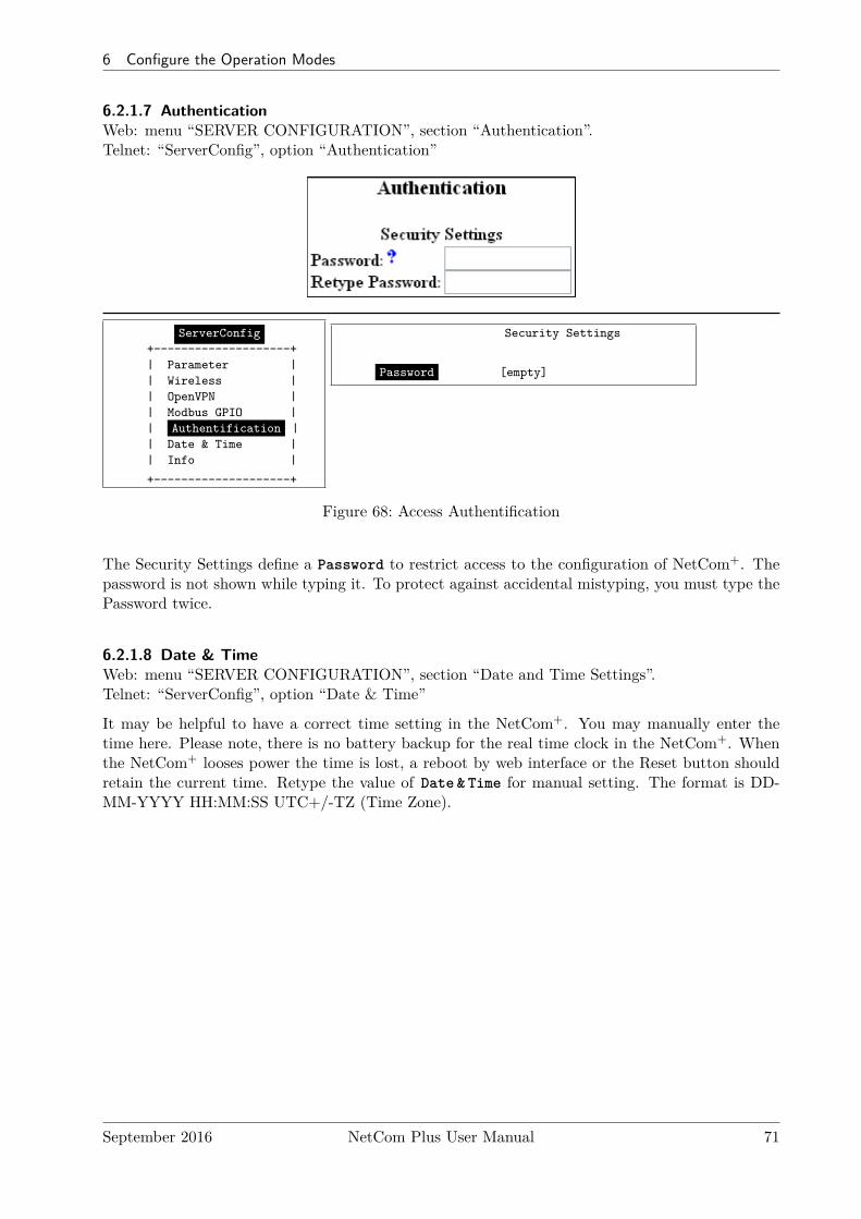
6 Configure the Operation Modes
6.2.1.7 AuthenticationWeb: menu “SERVER CONFIGURATION”, section “Authentication”.Telnet: “ServerConfig”, option “Authentication”
ServerConfig+--------------------+| Parameter || Wireless || OpenVPN || Modbus GPIO || Authentification || Date & Time || Info |
+--------------------+
Security Settings
Password [empty]
Figure 68: Access Authentification
The Security Settings define a Password to restrict access to the configuration of NetCom+. Thepassword is not shown while typing it. To protect against accidental mistyping, you must type thePassword twice.
6.2.1.8 Date & TimeWeb: menu “SERVER CONFIGURATION”, section “Date and Time Settings”.Telnet: “ServerConfig”, option “Date & Time”
It may be helpful to have a correct time setting in the NetCom+. You may manually enter thetime here. Please note, there is no battery backup for the real time clock in the NetCom+. Whenthe NetCom+ looses power the time is lost, a reboot by web interface or the Reset button shouldretain the current time. Retype the value of Date & Time for manual setting. The format is DD-MM-YYYY HH:MM:SS UTC+/-TZ (Time Zone).
September 2016 NetCom Plus User Manual 71

6 Configure the Operation Modes
ServerConfig+--------------------+| Parameter || Wireless || OpenVPN || Modbus GPIO || Authentification || Date & Time || Info |
+--------------------+
Date and Time Settings
Date & Time [01-01-2000 01:00:23 UTC+1]
Simple Network Time Protocol
State IntervalMode IP AddressInterval [1800 ]
Server [81.7.16.58 ]
Figure 69: Date & Time Retrieval Options
It is possible to configure NetCom+ for automatic time retrieval via SNTP.
The State field has three possible settings:
• Off: disables automatic time retrieval.
• Startup: NetCom+ gets the time at reset or power on.
• Interval: NetCom+ repeats to retrieve time.
The parameter Mode is used to find the definition of the Time Server. In current firmware the timesource is defined by the IP Address.
The Interval in seconds instructs the NetCom+ to regularly check for an update of the internaltime settings. The Time Server may be given by IPAddress or by name. A name of course requiresa configured DNS server8.
6.2.1.9 SaveWeb: menu “SERVER CONFIGURATION”, at bottom.
At the bottom of the web page below all the options there is the button Save. This will store allconfigurations done here in the NetCom+. Selecting a different configuration section from the menu
8see at Server Parameter 6.2.1.2
September 2016 NetCom Plus User Manual 72
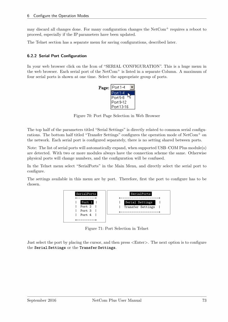
6 Configure the Operation Modes
may discard all changes done. For many configuration changes the NetCom+ requires a reboot toproceed, especially if the IP parameters have been updated.
The Telnet section has a separate menu for saving configurations, described later.
6.2.2 Serial Port Configuration
In your web browser click on the Icon of “SERIAL CONFIGURATION”. This is a huge menu inthe web browser. Each serial port of the NetCom+ is listed in a separate Column. A maximum offour serial ports is shown at one time. Select the appropriate group of ports.
Figure 70: Port Page Selection in Web Browser
The top half of the parameters titled “Serial Settings” is directly related to common serial configu-rations. The bottom half titled “Transfer Settings” configures the operation mode of NetCom+ onthe network. Each serial port is configured separately, there is no setting shared between ports.
Note: The list of serial ports will automatically expand, when supported USB–COM Plus module(s)are detected. With two or more modules always have the connection scheme the same. Otherwisephysical ports will change numbers, and the configuration will be confused.
In the Telnet menu select “SerialPorts” in the Main Menu, and directly select the serial port toconfigure.
The settings available in this menu are by port. Therefore, first the port to configure has to bechosen.
SerialPorts+----------+| Port 1 || Port 2 || Port 3 || Port 4 |
+----------+
SerialPorts+---------------------+| Serial Settings || Transfer Settings |
+---------------------+
Figure 71: Port Selection in Telnet
Just select the port by placing the cursor, and then press <Enter>. The next option is to configurethe Serial Settings or the Transfer Settings.
September 2016 NetCom Plus User Manual 73
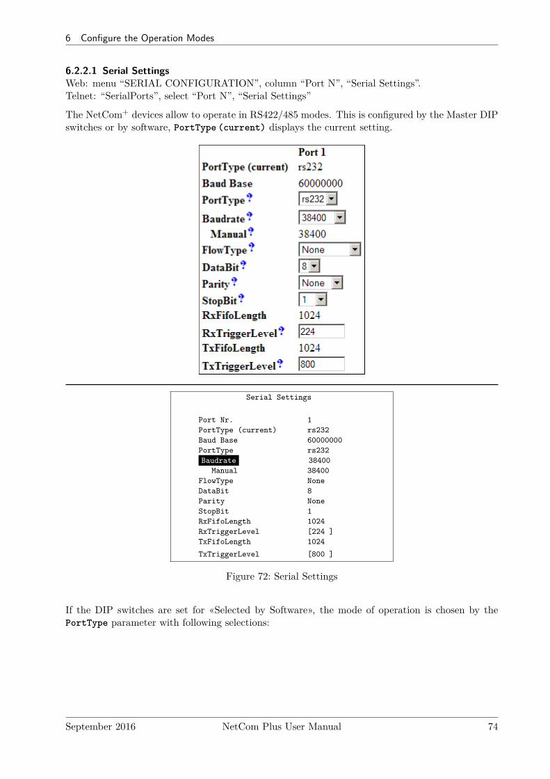
6 Configure the Operation Modes
6.2.2.1 Serial SettingsWeb: menu “SERIAL CONFIGURATION”, column “Port N”, “Serial Settings”.Telnet: “SerialPorts”, select “Port N”, “Serial Settings”
The NetCom+ devices allow to operate in RS422/485 modes. This is configured by the Master DIPswitches or by software, PortType (current) displays the current setting.
Serial Settings
Port Nr. 1PortType (current) rs232Baud Base 60000000PortType rs232Baudrate 38400
Manual 38400FlowType NoneDataBit 8Parity NoneStopBit 1RxFifoLength 1024RxTriggerLevel [224 ]TxFifoLength 1024
TxTriggerLevel [800 ]
Figure 72: Serial Settings
If the DIP switches are set for «Selected by Software», the mode of operation is chosen by thePortType parameter with following selections:
September 2016 NetCom Plus User Manual 74
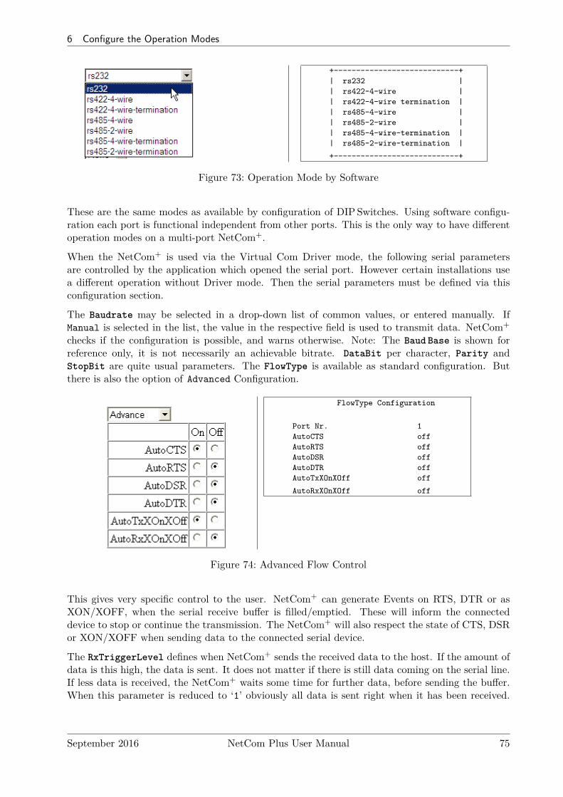
6 Configure the Operation Modes
+----------------------------+| rs232 || rs422-4-wire || rs422-4-wire termination || rs485-4-wire || rs485-2-wire || rs485-4-wire-termination || rs485-2-wire-termination |
+----------------------------+
Figure 73: Operation Mode by Software
These are the same modes as available by configuration of DIPSwitches. Using software configu-ration each port is functional independent from other ports. This is the only way to have differentoperation modes on a multi-port NetCom+.
When the NetCom+ is used via the Virtual Com Driver mode, the following serial parametersare controlled by the application which opened the serial port. However certain installations usea different operation without Driver mode. Then the serial parameters must be defined via thisconfiguration section.
The Baudrate may be selected in a drop-down list of common values, or entered manually. IfManual is selected in the list, the value in the respective field is used to transmit data. NetCom+
checks if the configuration is possible, and warns otherwise. Note: The Baud Base is shown forreference only, it is not necessarily an achievable bitrate. DataBit per character, Parity andStopBit are quite usual parameters. The FlowType is available as standard configuration. Butthere is also the option of Advanced Configuration.
FlowType Configuration
Port Nr. 1AutoCTS offAutoRTS offAutoDSR offAutoDTR offAutoTxXOnXOff off
AutoRxXOnXOff off
Figure 74: Advanced Flow Control
This gives very specific control to the user. NetCom+ can generate Events on RTS, DTR or asXON/XOFF, when the serial receive buffer is filled/emptied. These will inform the connecteddevice to stop or continue the transmission. The NetCom+ will also respect the state of CTS, DSRor XON/XOFF when sending data to the connected serial device.
The RxTriggerLevel defines when NetCom+ sends the received data to the host. If the amount ofdata is this high, the data is sent. It does not matter if there is still data coming on the serial line.If less data is received, the NetCom+ waits some time for further data, before sending the buffer.When this parameter is reduced to ‘1’ obviously all data is sent right when it has been received.
September 2016 NetCom Plus User Manual 75
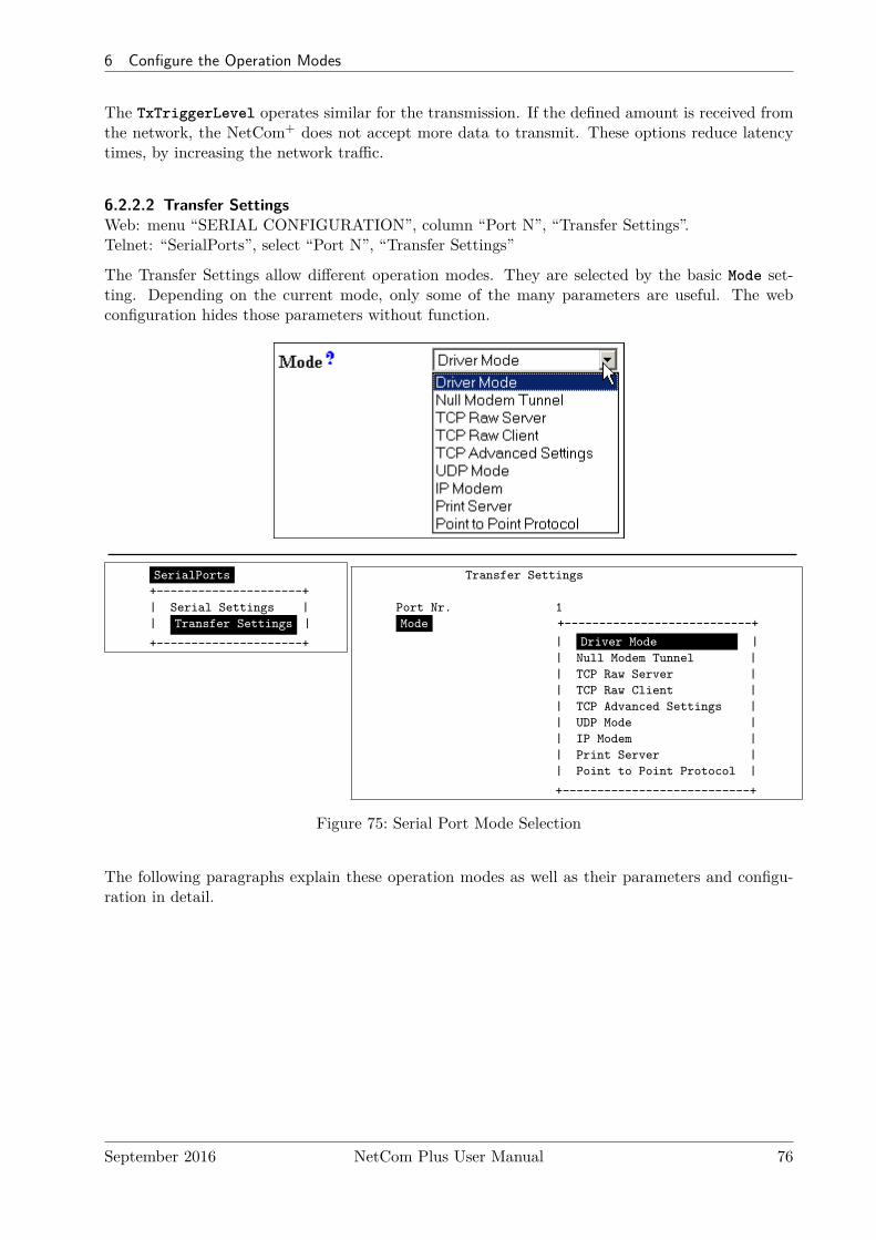
6 Configure the Operation Modes
The TxTriggerLevel operates similar for the transmission. If the defined amount is received fromthe network, the NetCom+ does not accept more data to transmit. These options reduce latencytimes, by increasing the network traffic.
6.2.2.2 Transfer SettingsWeb: menu “SERIAL CONFIGURATION”, column “Port N”, “Transfer Settings”.Telnet: “SerialPorts”, select “Port N”, “Transfer Settings”
The Transfer Settings allow different operation modes. They are selected by the basic Mode set-ting. Depending on the current mode, only some of the many parameters are useful. The webconfiguration hides those parameters without function.
SerialPorts+---------------------+| Serial Settings || Transfer Settings |
+---------------------+
Transfer Settings
Port Nr. 1Mode +---------------------------+
| Driver Mode || Null Modem Tunnel || TCP Raw Server || TCP Raw Client || TCP Advanced Settings || UDP Mode || IP Modem || Print Server || Point to Point Protocol |
+---------------------------+
Figure 75: Serial Port Mode Selection
The following paragraphs explain these operation modes as well as their parameters and configu-ration in detail.
September 2016 NetCom Plus User Manual 76
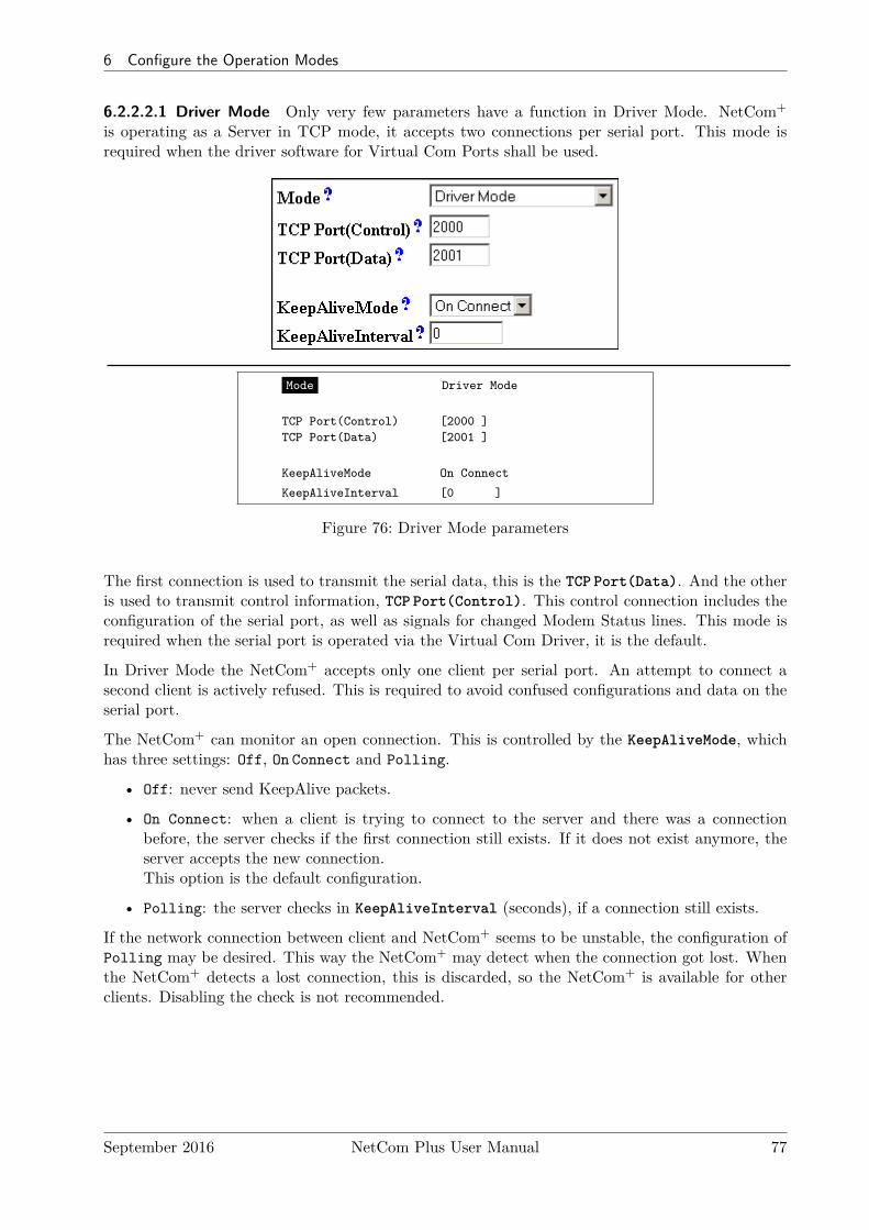
6 Configure the Operation Modes
6.2.2.2.1 Driver Mode Only very few parameters have a function in Driver Mode. NetCom+
is operating as a Server in TCP mode, it accepts two connections per serial port. This mode isrequired when the driver software for Virtual Com Ports shall be used.
Mode Driver Mode
TCP Port(Control) [2000 ]TCP Port(Data) [2001 ]
KeepAliveMode On Connect
KeepAliveInterval [0 ]
Figure 76: Driver Mode parameters
The first connection is used to transmit the serial data, this is the TCP Port(Data). And the otheris used to transmit control information, TCP Port(Control). This control connection includes theconfiguration of the serial port, as well as signals for changed Modem Status lines. This mode isrequired when the serial port is operated via the Virtual Com Driver, it is the default.
In Driver Mode the NetCom+ accepts only one client per serial port. An attempt to connect asecond client is actively refused. This is required to avoid confused configurations and data on theserial port.
The NetCom+ can monitor an open connection. This is controlled by the KeepAliveMode, whichhas three settings: Off, On Connect and Polling.
• Off: never send KeepAlive packets.
• On Connect: when a client is trying to connect to the server and there was a connectionbefore, the server checks if the first connection still exists. If it does not exist anymore, theserver accepts the new connection.This option is the default configuration.
• Polling: the server checks in KeepAliveInterval (seconds), if a connection still exists.
If the network connection between client and NetCom+ seems to be unstable, the configuration ofPolling may be desired. This way the NetCom+ may detect when the connection got lost. Whenthe NetCom+ detects a lost connection, this is discarded, so the NetCom+ is available for otherclients. Disabling the check is not recommended.
September 2016 NetCom Plus User Manual 77
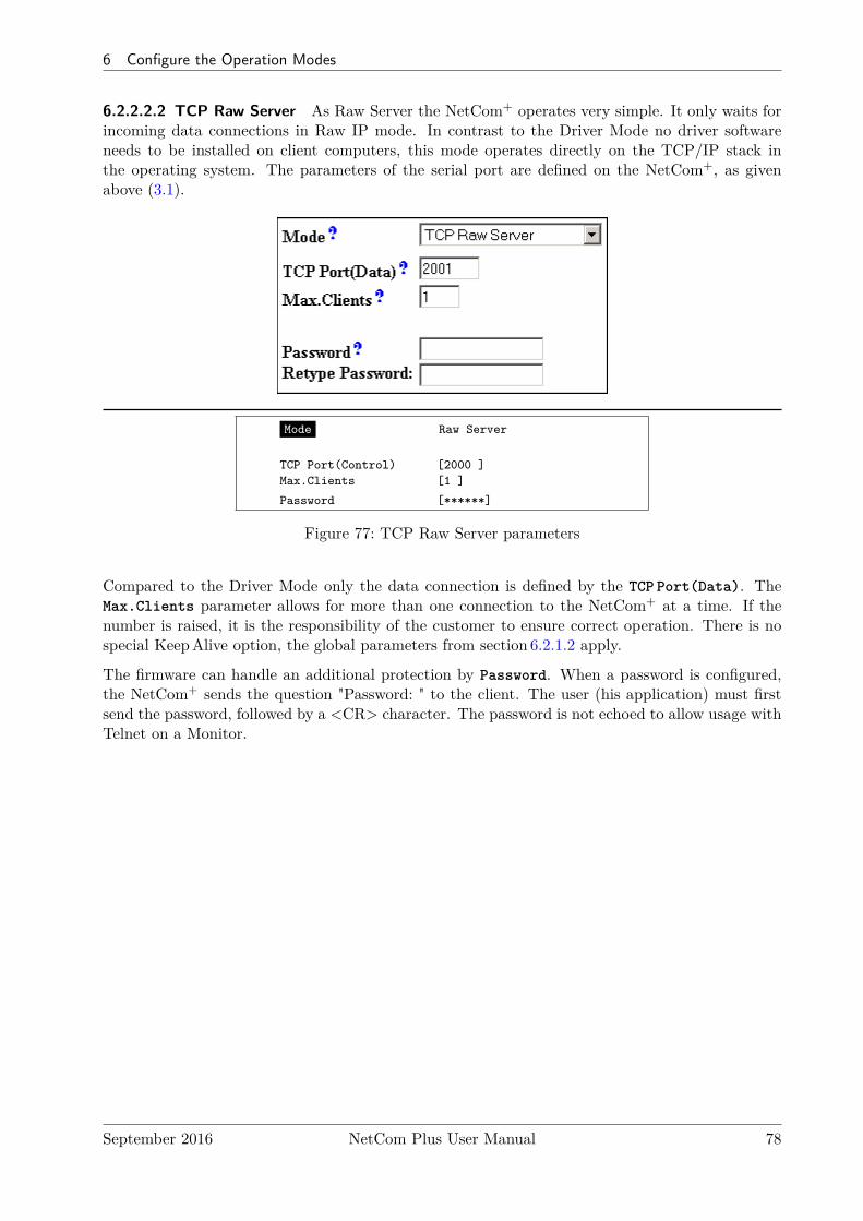
6 Configure the Operation Modes
6.2.2.2.2 TCP Raw Server As Raw Server the NetCom+ operates very simple. It only waits forincoming data connections in Raw IP mode. In contrast to the Driver Mode no driver softwareneeds to be installed on client computers, this mode operates directly on the TCP/IP stack inthe operating system. The parameters of the serial port are defined on the NetCom+, as givenabove (3.1).
Mode Raw Server
TCP Port(Control) [2000 ]Max.Clients [1 ]
Password [******]
Figure 77: TCP Raw Server parameters
Compared to the Driver Mode only the data connection is defined by the TCP Port(Data). TheMax.Clients parameter allows for more than one connection to the NetCom+ at a time. If thenumber is raised, it is the responsibility of the customer to ensure correct operation. There is nospecial KeepAlive option, the global parameters from section 6.2.1.2 apply.
The firmware can handle an additional protection by Password. When a password is configured,the NetCom+ sends the question "Password: " to the client. The user (his application) must firstsend the password, followed by a <CR> character. The password is not echoed to allow usage withTelnet on a Monitor.
September 2016 NetCom Plus User Manual 78

6 Configure the Operation Modes
6.2.2.2.3 TCP Raw Client Also as Raw Client the NetCom+ requires very few parameters. Theclient computer operates via the TCP/IP stack as in 6.2.2.2.2, but now the computers waits forincoming connections opened by the NetCom+. Using this mode several NetCom+ may connectto the same server software installation. The parameters of the serial port are defined on theNetCom+, as given above (3.1). When the client computer is another NetCom+ in TCP RawServer mode, this will virtually connect the devices attached to the serial port.
Mode Raw Client
Destination [192.168.1.5:2001 ]Connect Triggered
ShortHoldTime [0 ]
Figure 78: TCP Raw Client parameters
Under certain conditions the NetCom+ establishes a Raw TCP connection to a pre-defined Des-tination. The Destination can hold multiple hosts as targets for a connection. They are en-tered as a comma separated list of DNS names or IPAddresses. Each destination will havea TCP port number, separated by a colon. Instead of a single IPAddress or DNS name, arange of IPAddresses is also valid. This range must be followed by the TCP port number, asin 192.168.254.12-192.168.254.17:2077.
The parameter Connect defines if NetCom+ uses the connections as Permanent, Triggered or byDSR. With Permanent the NetCom+ attempts to open the connection as soon as it is available. InTriggered mode any activity on the serial ports establishes the connection, inactivity of longerthan the ShortHoldTime cause NetCom+ to close the connection. With DSR the TCP-connectionsfollow the state of the DSR signal at the NetCom+ serial port. When it becomes active they areestablished, until DSR becomes inactive. At that moment the connections are dropped.
September 2016 NetCom Plus User Manual 79
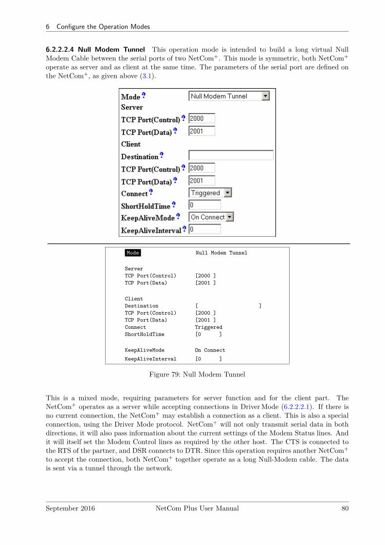
6 Configure the Operation Modes
6.2.2.2.4 Null Modem Tunnel This operation mode is intended to build a long virtual NullModem Cable between the serial ports of two NetCom+. This mode is symmetric, both NetCom+
operate as server and as client at the same time. The parameters of the serial port are defined onthe NetCom+, as given above (3.1).
Mode Null Modem Tunnel
ServerTCP Port(Control) [2000 ]TCP Port(Data) [2001 ]
ClientDestination [ ]TCP Port(Control) [2000 ]TCP Port(Data) [2001 ]Connect TriggeredShortHoldTime [0 ]
KeepAliveMode On Connect
KeepAliveInterval [0 ]
Figure 79: Null Modem Tunnel
This is a mixed mode, requiring parameters for server function and for the client part. TheNetCom+ operates as a server while accepting connections in DriverMode (6.2.2.2.1). If there isno current connection, the NetCom+ may establish a connection as a client. This is also a specialconnection, using the Driver Mode protocol. NetCom+ will not only transmit serial data in bothdirections, it will also pass information about the current settings of the Modem Status lines. Andit will itself set the Modem Control lines as required by the other host. The CTS is connected tothe RTS of the partner, and DSR connects to DTR. Since this operation requires another NetCom+
to accept the connection, both NetCom+ together operate as a long Null-Modem cable. The datais sent via a tunnel through the network.
September 2016 NetCom Plus User Manual 80
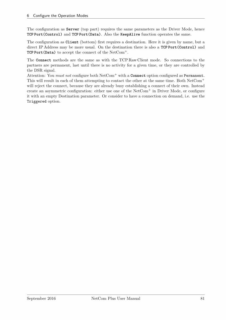
6 Configure the Operation Modes
The configuration as Server (top part) requires the same parameters as the Driver Mode, henceTCP Port(Control) and TCP Port(Data). Also the KeepAlive function operates the same.
The configuration as Client (bottom) first requires a destination. Here it is given by name, but adirect IPAddress may be more usual. On the destination there is also a TCP Port(Control) andTCP Port(Data) to accept the connect of the NetCom+.
The Connect methods are the same as with the TCPRawClient mode. So connections to thepartners are permanent, last until there is no activity for a given time, or they are controlled bythe DSR signal.Attention: You must not configure both NetCom+ with a Connect option configured as Permanent.This will result in each of them attempting to contact the other at the same time. Both NetCom+
will reject the connect, because they are already busy establishing a connect of their own. Insteadcreate an asymmetric configuration: either use one of the NetCom+ in Driver Mode, or configureit with an empty Destination parameter. Or consider to have a connection on demand, i.e. use theTriggered option.
September 2016 NetCom Plus User Manual 81
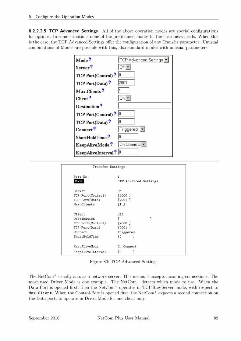
6 Configure the Operation Modes
6.2.2.2.5 TCP Advanced Settings All of the above operation modes are special configurationsfor options. In some situations none of the pre-defined modes fit the customers needs. When thisis the case, the TCP Advanced Settings offer the configuration of any Transfer parameter. Unusualcombinations of Modes are possible with this, also standard modes with unusual parameters.
Transfer Settings
Port Nr. 1Mode TCP Advanced Settings
Server OnTCP Port(Control) [2000 ]TCP Port(Data) [2001 ]Max.Clients [1 ]
Client OffDestination [ ]TCP Port(Control) [2000 ]TCP Port(Data) [2001 ]Connect TriggeredShortHoldTime [0 ]
KeepAliveMode On Connect
KeepAliveInterval [0 ]
Figure 80: TCP Advanced Settings
The NetCom+ usually acts as a network server. This means it accepts incoming connections. Themost used Driver Mode is one example. The NetCom+ detects which mode to use. When theData-Port is opened first, then the NetCom+ operates in TCPRawServer mode, with respect toMax.Client. When the Control-Port is opened first, the NetCom+ expects a second connection onthe Data port, to operate in DriverMode for one client only.
September 2016 NetCom Plus User Manual 82
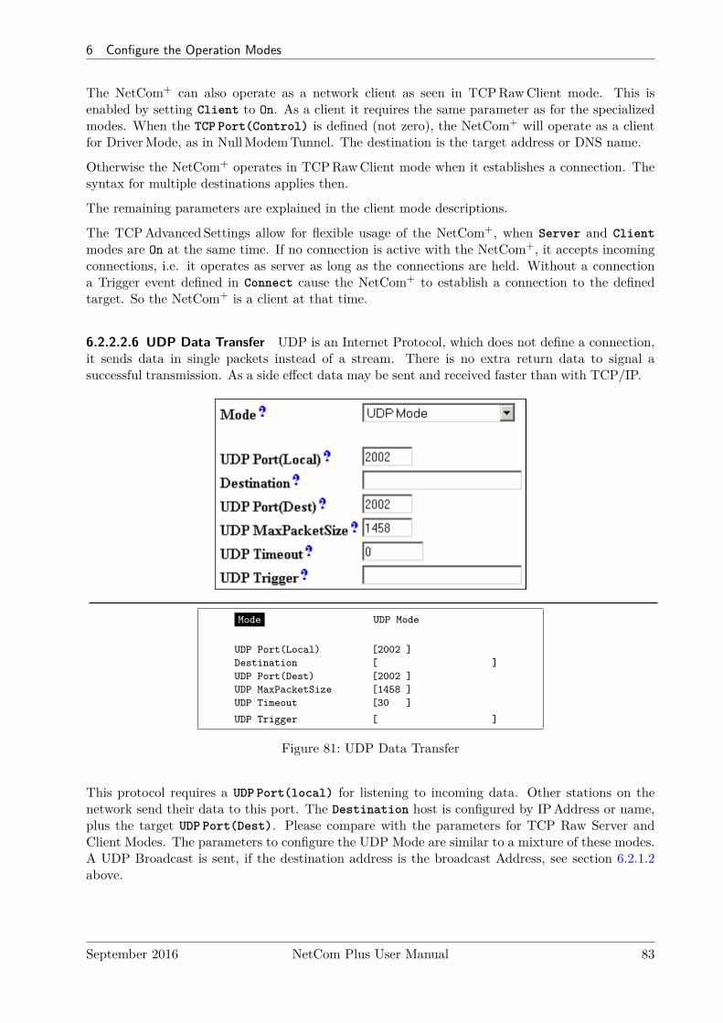
6 Configure the Operation Modes
The NetCom+ can also operate as a network client as seen in TCPRawClient mode. This isenabled by setting Client to On. As a client it requires the same parameter as for the specializedmodes. When the TCP Port(Control) is defined (not zero), the NetCom+ will operate as a clientfor DriverMode, as in NullModemTunnel. The destination is the target address or DNS name.
Otherwise the NetCom+ operates in TCPRawClient mode when it establishes a connection. Thesyntax for multiple destinations applies then.
The remaining parameters are explained in the client mode descriptions.
The TCPAdvanced Settings allow for flexible usage of the NetCom+, when Server and Clientmodes are On at the same time. If no connection is active with the NetCom+, it accepts incomingconnections, i.e. it operates as server as long as the connections are held. Without a connectiona Trigger event defined in Connect cause the NetCom+ to establish a connection to the definedtarget. So the NetCom+ is a client at that time.
6.2.2.2.6 UDP Data Transfer UDP is an Internet Protocol, which does not define a connection,it sends data in single packets instead of a stream. There is no extra return data to signal asuccessful transmission. As a side effect data may be sent and received faster than with TCP/IP.
Mode UDP Mode
UDP Port(Local) [2002 ]Destination [ ]UDP Port(Dest) [2002 ]UDP MaxPacketSize [1458 ]UDP Timeout [30 ]
UDP Trigger [ ]
Figure 81: UDP Data Transfer
This protocol requires a UDP Port(local) for listening to incoming data. Other stations on thenetwork send their data to this port. The Destination host is configured by IPAddress or name,plus the target UDP Port(Dest). Please compare with the parameters for TCP Raw Server andClient Modes. The parameters to configure the UDP Mode are similar to a mixture of these modes.A UDP Broadcast is sent, if the destination address is the broadcast Address, see section 6.2.1.2above.
September 2016 NetCom Plus User Manual 83
6 Configure the Operation Modes
Since there is no connection, data can not be sent in a stream. UDP uses packages. There areseveral ways to define the content for a package.
UDP MaxPacketSize is a limit for the size of UDP packets. When the amount of data received on theserial port reaches this limit, the UDP Frame is assembled and sent to the destination.
UDP Timeout defines when the NetCom+ sends the received data as a UDP Frame. If the receptionof serial data is interrupted for this time (in milliseconds), the data sampled so far issent to the destination. A value of zero causes all data to be sent immediately, use“-1” to disable the function of timeout trigger. A good value to start with is 30, if nospecific parameters are given by the external devices. This is the default since fimrwareversion 3.3.5
UDP Trigger defines a sequence of characters. As soon as this sequence is detected in the receiveddata, all data up to the end of this Trigger is sent to the destination. In most situationssuch a Trigger includes control or other special characters. Enter them numeric: as\xHH where HH is the hexadecadic code of the character, or as \OOO where OOO isthe octal code of the character. The backslash itself must be doubled as \\.
If none of these options is used, the packets definition is not specified. This will result in unpre-dictable separation of serial data, depending on internal hardware behaviour. Typically this is nothandled good by the application software.
6.2.2.2.7 IP-Modem The serial port of a NetCom+ may mimic (emulate) a serial modem. Thereis the separate section 8 defining this functionality. Here are the basic network parameters only.
Mode IP Modem
TCP Port(Data) [2001 ]Destination [ ]
IP Modem Config [ ]
Figure 82: IP-Modem
A serial modem accepts connections from a phone line, while an IP Modem accepts connectionsfrom the network, in this case via TCP/IP. The TCP port for this is defined as the TCP Port(Data),similar to TCPRawServer mode. This is the only parameter required to set here.
All other values are normally defined by AT-commands via the serial port. However for short,Destination allows for up to four predefined targets, available with special Dial commands. TheIP Modem Config is known as the Init String in standard modems.
September 2016 NetCom Plus User Manual 84
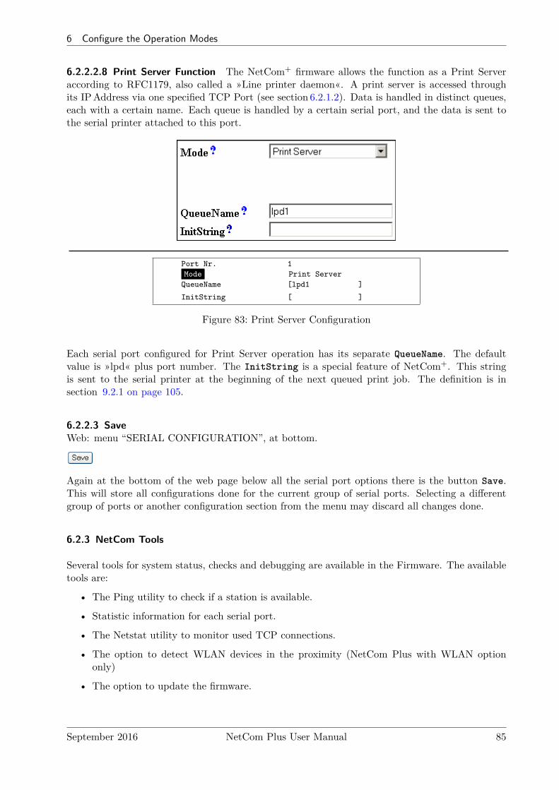
6 Configure the Operation Modes
6.2.2.2.8 Print Server Function The NetCom+ firmware allows the function as a Print Serveraccording to RFC1179, also called a »Line printer daemon«. A print server is accessed throughits IPAddress via one specified TCP Port (see section 6.2.1.2). Data is handled in distinct queues,each with a certain name. Each queue is handled by a certain serial port, and the data is sent tothe serial printer attached to this port.
Port Nr. 1Mode Print Server
QueueName [lpd1 ]
InitString [ ]
Figure 83: Print Server Configuration
Each serial port configured for Print Server operation has its separate QueueName. The defaultvalue is »lpd« plus port number. The InitString is a special feature of NetCom+. This stringis sent to the serial printer at the beginning of the next queued print job. The definition is insection 9.2.1 on page 105.
6.2.2.3 SaveWeb: menu “SERIAL CONFIGURATION”, at bottom.
Again at the bottom of the web page below all the serial port options there is the button Save.This will store all configurations done for the current group of serial ports. Selecting a differentgroup of ports or another configuration section from the menu may discard all changes done.
6.2.3 NetCom Tools
Several tools for system status, checks and debugging are available in the Firmware. The availabletools are:
• The Ping utility to check if a station is available.
• Statistic information for each serial port.
• The Netstat utility to monitor used TCP connections.
• The option to detect WLAN devices in the proximity (NetCom Plus with WLAN optiononly)
• The option to update the firmware.
September 2016 NetCom Plus User Manual 85
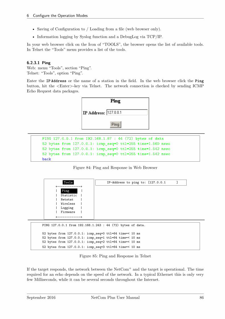
6 Configure the Operation Modes
• Saving of Configuration to / Loading from a file (web browser only).
• Information logging by Syslog function and a DebugLog via TCP/IP.
In your web browser click on the Icon of “TOOLS”, the browser opens the list of available tools.In Telnet the “Tools” menu provides a list of the tools.
6.2.3.1 PingWeb: menu “Tools”, section “Ping”.Telnet: “Tools”, option “Ping”.
Enter the IP Address or the name of a station in the field. In the web browser click the Pingbutton, hit the <Enter>-key via Telnet. The network connection is checked by sending ICMPEcho Request data packages.
PING 127.0.0.1 from 192.168.1.87 : 44 (72) bytes of data52 bytes from 127.0.0.1: icmp_seq=0 ttl=255 time=1.560 msec52 bytes from 127.0.0.1: icmp_seq=0 ttl=255 time=1.542 msec52 bytes from 127.0.0.1: icmp_seq=0 ttl=255 time=1.542 msecback
Figure 84: Ping and Response in Web Browser
Tools+-------------+| Ping || Statistic || Netstat || Wireless || Logging || Firmware |
+-------------+
IP-Address to ping to: [127.0.0.1 ]
PING 127.0.0.1 from 192.168.1.243 : 44 (72) bytes of data.
52 bytes from 127.0.0.1: icmp_seq=0 ttl=64 time=< 10 ms52 bytes from 127.0.0.1: icmp_seq=1 ttl=64 time=< 10 ms52 bytes from 127.0.0.1: icmp_seq=2 ttl=64 time=< 10 ms
52 bytes from 127.0.0.1: icmp_seq=3 ttl=64 time=< 10 ms
Figure 85: Ping and Response in Telnet
If the target responds, the network between the NetCom+ and the target is operational. The timerequired for an echo depends on the speed of the network. In a typical Ethernet this is only veryfew Milliseconds, while it can be several seconds throughout the Internet.
September 2016 NetCom Plus User Manual 86
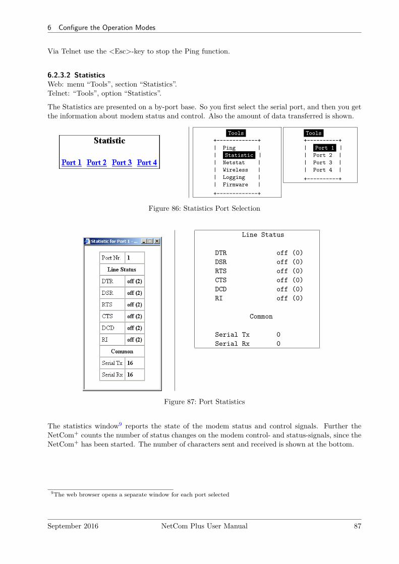
6 Configure the Operation Modes
Via Telnet use the <Esc>-key to stop the Ping function.
6.2.3.2 StatisticsWeb: menu “Tools”, section “Statistics”.Telnet: “Tools”, option “Statistics”.
The Statistics are presented on a by-port base. So you first select the serial port, and then you getthe information about modem status and control. Also the amount of data transferred is shown.
Tools+-------------+| Ping || Statistic || Netstat || Wireless || Logging || Firmware |
+-------------+
Tools+----------+| Port 1 || Port 2 || Port 3 || Port 4 |
+----------+
Figure 86: Statistics Port Selection
Line Status
DTR off (0)DSR off (0)RTS off (0)CTS off (0)DCD off (0)RI off (0)
Common
Serial Tx 0Serial Rx 0
Figure 87: Port Statistics
The statistics window9 reports the state of the modem status and control signals. Further theNetCom+ counts the number of status changes on the modem control- and status-signals, since theNetCom+ has been started. The number of characters sent and received is shown at the bottom.
9The web browser opens a separate window for each port selected
September 2016 NetCom Plus User Manual 87
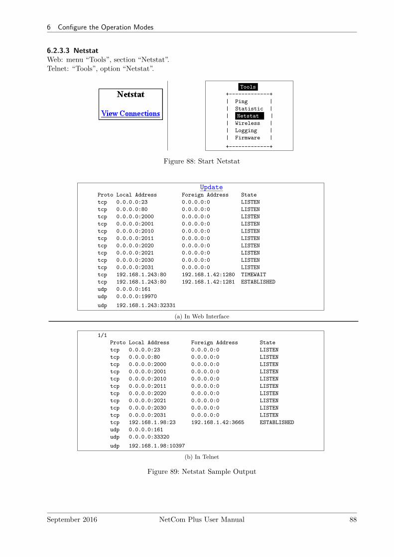
6 Configure the Operation Modes
6.2.3.3 NetstatWeb: menu “Tools”, section “Netstat”.Telnet: “Tools”, option “Netstat”.
Tools+-------------+| Ping || Statistic || Netstat || Wireless || Logging || Firmware |
+-------------+
Figure 88: Start Netstat
UpdateProto Local Address Foreign Address Statetcp 0.0.0.0:23 0.0.0.0:0 LISTENtcp 0.0.0.0:80 0.0.0.0:0 LISTENtcp 0.0.0.0:2000 0.0.0.0:0 LISTENtcp 0.0.0.0:2001 0.0.0.0:0 LISTENtcp 0.0.0.0:2010 0.0.0.0:0 LISTENtcp 0.0.0.0:2011 0.0.0.0:0 LISTENtcp 0.0.0.0:2020 0.0.0.0:0 LISTENtcp 0.0.0.0:2021 0.0.0.0:0 LISTENtcp 0.0.0.0:2030 0.0.0.0:0 LISTENtcp 0.0.0.0:2031 0.0.0.0:0 LISTENtcp 192.168.1.243:80 192.168.1.42:1280 TIMEWAITtcp 192.168.1.243:80 192.168.1.42:1281 ESTABLISHEDudp 0.0.0.0:161udp 0.0.0.0:19970
udp 192.168.1.243:32331
(a) In Web Interface
1/1Proto Local Address Foreign Address Statetcp 0.0.0.0:23 0.0.0.0:0 LISTENtcp 0.0.0.0:80 0.0.0.0:0 LISTENtcp 0.0.0.0:2000 0.0.0.0:0 LISTENtcp 0.0.0.0:2001 0.0.0.0:0 LISTENtcp 0.0.0.0:2010 0.0.0.0:0 LISTENtcp 0.0.0.0:2011 0.0.0.0:0 LISTENtcp 0.0.0.0:2020 0.0.0.0:0 LISTENtcp 0.0.0.0:2021 0.0.0.0:0 LISTENtcp 0.0.0.0:2030 0.0.0.0:0 LISTENtcp 0.0.0.0:2031 0.0.0.0:0 LISTENtcp 192.168.1.98:23 192.168.1.42:3665 ESTABLISHEDudp 0.0.0.0:161udp 0.0.0.0:33320
udp 192.168.1.98:10397
(b) In Telnet
Figure 89: Netstat Sample Output
September 2016 NetCom Plus User Manual 88
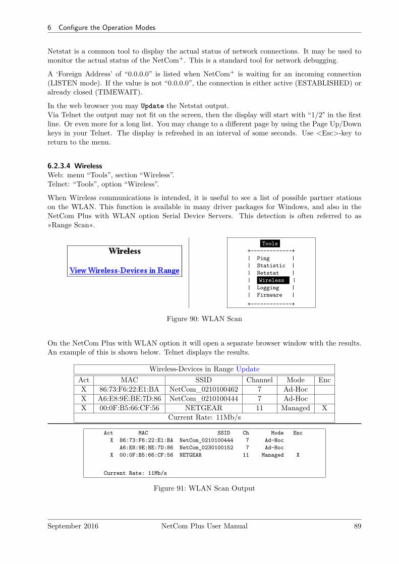
6 Configure the Operation Modes
Netstat is a common tool to display the actual status of network connections. It may be used tomonitor the actual status of the NetCom+. This is a standard tool for network debugging.
A ‘Foreign Address’ of “0.0.0.0” is listed when NetCom+ is waiting for an incoming connection(LISTEN mode). If the value is not “0.0.0.0”, the connection is either active (ESTABLISHED) oralready closed (TIMEWAIT).
In the web browser you may Update the Netstat output.Via Telnet the output may not fit on the screen, then the display will start with “1/2" in the firstline. Or even more for a long list. You may change to a different page by using the Page Up/Downkeys in your Telnet. The display is refreshed in an interval of some seconds. Use <Esc>-key toreturn to the menu.
6.2.3.4 WirelessWeb: menu “Tools”, section “Wireless”.Telnet: “Tools”, option “Wireless”.
When Wireless communications is intended, it is useful to see a list of possible partner stationson the WLAN. This function is available in many driver packages for Windows, and also in theNetCom Plus with WLAN option Serial Device Servers. This detection is often referred to as»Range Scan«.
Tools+-------------+| Ping || Statistic || Netstat || Wireless || Logging || Firmware |
+-------------+
Figure 90: WLAN Scan
On the NetCom Plus with WLAN option it will open a separate browser window with the results.An example of this is shown below. Telnet displays the results.
Wireless-Devices in Range UpdateAct MAC SSID Channel Mode EncX 86:73:F6:22:E1:BA NetCom_0210100462 7 Ad-HocX A6:E8:9E:BE:7D:86 NetCom_0210100444 7 Ad-HocX 00:0F:B5:66:CF:56 NETGEAR 11 Managed X
Current Rate: 11Mb/s
Act MAC SSID Ch Mode EncX 86:73:F6:22:E1:BA NetCom_0210100444 7 Ad-Hoc
A6:E8:9E:BE:7D:86 NetCom_0230100152 7 Ad-HocX 00:0F:B5:66:CF:56 NETGEAR 11 Managed X
Current Rate: 11Mb/s
Figure 91: WLAN Scan Output
September 2016 NetCom Plus User Manual 89
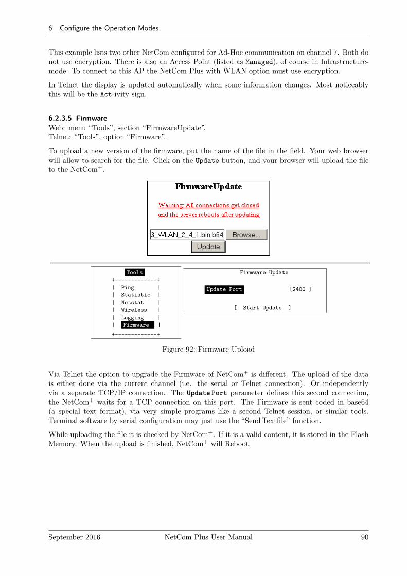
6 Configure the Operation Modes
This example lists two other NetCom configured for Ad-Hoc communication on channel 7. Both donot use encryption. There is also an Access Point (listed as Managed), of course in Infrastructure-mode. To connect to this AP the NetCom Plus with WLAN option must use encryption.
In Telnet the display is updated automatically when some information changes. Most noticeablythis will be the Act-ivity sign.
6.2.3.5 FirmwareWeb: menu “Tools”, section “FirmwareUpdate”.Telnet: “Tools”, option “Firmware”.
To upload a new version of the firmware, put the name of the file in the field. Your web browserwill allow to search for the file. Click on the Update button, and your browser will upload the fileto the NetCom+.
Tools+-------------+| Ping || Statistic || Netstat || Wireless || Logging || Firmware |
+-------------+
Firmware Update
Update Port [2400 ]
[ Start Update ]
Figure 92: Firmware Upload
Via Telnet the option to upgrade the Firmware of NetCom+ is different. The upload of the datais either done via the current channel (i.e. the serial or Telnet connection). Or independentlyvia a separate TCP/IP connection. The Update Port parameter defines this second connection,the NetCom+ waits for a TCP connection on this port. The Firmware is sent coded in base64(a special text format), via very simple programs like a second Telnet session, or similar tools.Terminal software by serial configuration may just use the “SendTextfile” function.
While uploading the file it is checked by NetCom+. If it is a valid content, it is stored in the FlashMemory. When the upload is finished, NetCom+ will Reboot.
September 2016 NetCom Plus User Manual 90
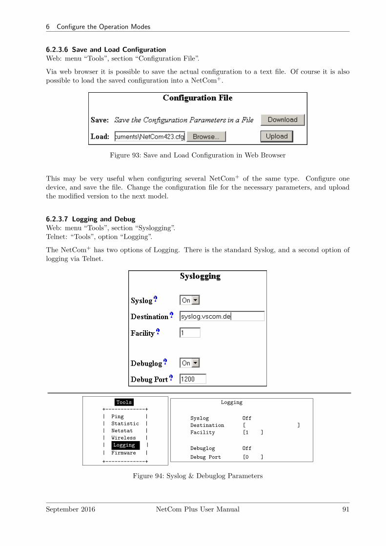
6 Configure the Operation Modes
6.2.3.6 Save and Load ConfigurationWeb: menu “Tools”, section “Configuration File”.
Via web browser it is possible to save the actual configuration to a text file. Of course it is alsopossible to load the saved configuration into a NetCom+.
Figure 93: Save and Load Configuration in Web Browser
This may be very useful when configuring several NetCom+ of the same type. Configure onedevice, and save the file. Change the configuration file for the necessary parameters, and uploadthe modified version to the next model.
6.2.3.7 Logging and DebugWeb: menu “Tools”, section “Syslogging”.Telnet: “Tools”, option “Logging”.
The NetCom+ has two options of Logging. There is the standard Syslog, and a second option oflogging via Telnet.
Tools+-------------+| Ping || Statistic || Netstat || Wireless || Logging || Firmware |
+-------------+
Logging
Syslog OffDestination [ ]Facility [1 ]
Debuglog Off
Debug Port [0 ]
Figure 94: Syslog & Debuglog Parameters
September 2016 NetCom Plus User Manual 91
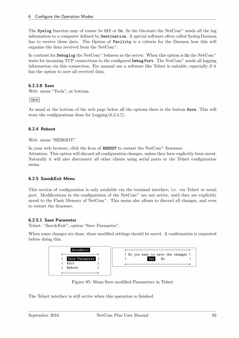
6 Configure the Operation Modes
The Syslog function may of course be Off or On. In the On-state the NetCom+ sends all the loginformation to a computer defined by Destination. A special software often called SyslogDaemonhas to receive these data. The Option of Facility is a criteria for the Daemon how this willorganize the data received from the NetCom+.
In contrast for Debuglog the NetCom+ behaves as the server. When this option is On the NetCom+
waits for incoming TCP connections to the configured Debug Port. The NetCom+ sends all logginginformation via this connection. For manual use a software like Telnet is suitable, especially if ithas the option to save all received data.
6.2.3.8 SaveWeb: menu “Tools”, at bottom.
As usual at the bottom of the web page below all the options there is the button Save. This willstore the configurations done for Logging (6.2.3.7).
6.2.4 Reboot
Web: menu “REBOOT”.
In your web browser, click the Icon of REBOOT to restart the NetCom+ firmware.Attention: This option will discard all configuration changes, unless they have explicitly been saved.Naturally it will also disconnect all other clients using serial ports or the Telnet configurationmenu.
6.2.5 Save&Exit Menu
This section of configuration is only available via the terminal interface, i.e. via Telnet or serialport. Modifications in the configuration of the NetCom+ are not active, until they are explicitlysaved to the Flash Memory of NetCom+. This menu also allows to discard all changes, and evento restart the firmware.
6.2.5.1 Save ParameterTelnet: “Save&Exit”, option “Save Parameter”.
When some changes are done, these modified settings should be saved. A confirmation is requestedbefore doing this.
Save&Exit+------------------+| Save Parameter || Exit || Reboot |
+------------------+
+---------------------------------+| Do you want to save the changes || Yes No |
+---------------------------------+
Figure 95: Menu Save modified Parameters in Telnet
The Telnet interface is still active when this operation is finished.
September 2016 NetCom Plus User Manual 92

6 Configure the Operation Modes
6.2.5.2 ExitTelnet: “Save&Exit”, option “Exit”.
You will not be surprised, when you leave the menu by selecting this option. If you made anychanges of parameters, you must confirm to save these.
Save&Exit+------------------+| Save Parameter || Exit || Reboot |
+------------------+
+---------------------------------+| Do you want to save the changes || Yes No |
+---------------------------------+
Figure 96: Menu Exit from Configuration in Telnet
The NetCom+ terminates the Telnet interface when this operation is finished, even when themodifications are not saved to Flash Memory.
6.2.5.3 RebootTelnet: “Save&Exit”, option “Reboot”.
Users may restart the firmware of the NetCom+. Modified configurations are activated by therestart process. Such a restart is necessary for some changes like IP configuration, others do notrequire a restart.
Save&Exit+------------------+| Save Parameter || Exit || Reboot |
+------------------+
+---------------------------------+| Do you want to save the changes || Yes No |
+---------------------------------+
Figure 97: Exit and Reboot in Telnet
Also here, if parameters are changed during the session, confirmation for saving them is requested.Of course the Telnet configuration is closed, because all TCP connections are terminated by thereboot process.
6.3 Erase Configuration of NetCom
Sometimes it is required to clear any configuration done, and go back to the Factory Settings. Usersmight think this is possible with the Reset button. It is not done this way. The Reset button isjust a way to restart the NetCom+ without removing the power.
To make a clean configuration the DIP switches must be configured to the pattern of »Fac-tory settings«. Refer to Section 3.1 or to the table on top of the NetCom+ case. When this patternis chosen, the NetCom+ has to be restarted, by power off or by using the Reset button. This is forsecurity. When changing a DIP configuration, the »Factory settings« might appear by accident.So the NetCom+ requires to be restarted with this DIP pattern active to avoid accidental damageof the configuration. While restarting, the NetCom+ erases the current configuration, and replaces
September 2016 NetCom Plus User Manual 93

7 Operation in Linux
the parameter with the default values. When this is finished, the Power LED blinks once. Do notpower off or reset the NetCom+ before this blink is seen.The Ethernet cable should not be connected, because the NetCom+ uses DHCP in factory config-uration. Without an Ethernet cable it does not attempt to find a DHCP server, which makes fora faster reboot process.
7 Operation in Linux
In Linux there is no real tty driver available for NetCom Plus serial device servers. However for mostapplications this is not a problem, since Linux is very good in networking. Either the applicationcan contact the Serial Port on the NetCom+ via a TCP connection, or it may use a fixed ttyemulation of a serial port. In both configurations the parameters of the serial port are configuredon the NetCom+. Additionally the serial port is operating in the mode of TCP Raw Server, withone defined TCP port to connect to (see 6.2.2.1 on page 74 and 6.2.2.2.2 on page 78 for details).For the following sections the IP Address 192.168.1.198 is used, with 2001 as the TCP data portnumber. This may be the serial port of a NetCom Plus 113 serial device server.
7.1 Via Fixed TTY Pseudo Serial Port (socat)
There are applications designed to operate via serial ports, and via this only. So they want to opena device which behaves like a serial port, usually /dev/ttyS0 or /dev/modem. To create a pseudodevice of this type the program socat may be used.
socat pty , l i n k=/dev/netcom0 , raw , wa i t s l ave tcp : 192 . 168 . 1 . 249 : 2001&
This command creates a temporary pseudo tty device with the name as /dev/netcom0. Any nameis possible, as long as it does not conflict with already existing devices. The TCP connection willbe established to the serial port on NetCom+, but this is delayed until an application opens this/dev/netcom0. The connection will be established as raw (without modifying data).The terminating ’&’ in the line sends socat into background operation. It will terminate when/dev/netcom0 is closed by the application.
minicom −D /dev/netcom0
This command will then start the application minicom as an example. In this example the created/dev/netcom0 is used, so minicom operates via the serial port on the NetCom+. Even whenminicom attempts to configure the serial port, this has no effect on the NetCom+. When minicomis closed, the process of socat terminates as well. For next use socat must be started again, whichcan be done in a script also.
The specification as “Fixed TTY” defines that behavior. Applications may use the pseudo portlike a serial port, but the serial configuration is fixed. Any commands to change the configurationare accepted from the application, but they do not change the serial port operation.
September 2016 NetCom Plus User Manual 94
7 Operation in Linux
7.2 Via TCP Raw Server Mode
The application will use the IP Address of the NetCom+ with the configured TCP port number forthe intended serial port. Usually the first serial port uses 2001 as TCP data port, so as an exampleprogram here is the command line for telnet application:
t e l n e t 192 . 168 . 1 . 2 49 2001
This command will open a raw TCP connection to the NetCom+. This connection is raw (nomodification of data) because there is no initiation of the protocol known as Telnet (RFC854).Every byte received on the serial port is displayed on the screen. And all characters typed on thekeyboard are sent via the serial port to the connected device. The serial parameters used are storedin the NetCom+, e.g. 38400,8,n,1 without flow control. If RTS/CTS or a different mode of flowcontrol is configured, this is handled internally at the serial port inside the NetCom+.
Especially with telnet users often get confused by doubled characters on the screen. This is causedby a misconfiguration of telnet, in this case the option of local echo. The typed character is shownon the screen by telnet, and the serial device also sends back the character. The configuration oftelnet is beyond the scope of this manual.
Telnet is one example, other applications will use their own methods of configuation.
September 2016 NetCom Plus User Manual 95
8 IP Modem Function
8 IP Modem Function
The Firmware offers the function of IP Modem. Used in this mode, the serial port of the NetCom+
emulates a standard serial modem. Basically this means the NetCom+ will
a) answer to AT-commands on the serial port
b) establish a connection to a destination
c) inform the connected serial device of the connection
d) accept a TCP connection, and inform the serial device of that event
For connections the NetCom+ will use a TCP connection. This differs from a normal telephoneline, so there will be some modifications in the behavior. The target is an IPAddress, not a phonenumber. Also for hardware reasons the automatic baudrate detection used in today serial Modemsis not available. However this is not a problem at all, the IP Modem can be installed in Windowsas a Standard 33600bps Modem. There is an INF-file for ease of installation.
8.1 Some possible Scenarios
1. The customer has a remote management installation, operating via telephone line. Theselines may be in-house or through public phone systems to other destinations. The customerwants to reduce costs for these lines, management and possibly hardware, using the Intra- orInternet.
2. The customer wants to contact several stations from a central server. Because of frequenttarget changes he does not want to define the target by a Virtual Com Port.
3. Remotely distributed devices contact a central system by Modem. This is the reverse ofoption 1.
4. A computer without Network access shall have at least limited control on the connectionsestablished by a NetCom+.
5. Old fashioned BBS installations become accessible via Internet. The typical multi-modembox is replaced by a NetCom+ Server with multiple ports configured for IP Modem operation.
8.2 Serial Signals and Cables
A real modem provides the same signals as the serial port of a PC. However, where a signal is anoutput on the PC, it is an input to the modem, and vice versa. So in the NetCom+ the emulationof a modem must be incomplete. By exchanging RxD and TxD the data connection is fine, thesame happens for handshaking signals RTS and CTS. The DTR of the PC is connected to DSR ofNetCom+, this is simple. The RI may be ignored, some connectors for serial ports also do that.
However a real modem provides DSR and DCD to the PC. There is only the DTR left on NetCom+
to serve these signals. In most configurations the NetCom+-DTR serves as the DCD to the com-puter.
The cable must provide a DSR to the PC then, e.g. by shortcut to the PC-DTR. In some configu-rations the NetCom+-DTR must serve as the DSR. This is configurable by a command.
September 2016 NetCom Plus User Manual 96
8 IP Modem Function
The recommended cable connects as shown in this table. Please note, this installation does notuse the simply crossed signals. Especially the DSR of the PC is internally connected to the DTRof the PC.
DB9m PC IP-Modem DB9m DB9f3 TxD —— RxD 2 32 RxD —— TxD 3 27 RTS —— CTS 8 78 CTS —— RTS 7 86 DSR PC-DTR (internal loop-back)4 DTR —— DSR 6 41 DCD —— DTR 4 65 GND —— GND 5 5
Table 19: IP Modem cable
The limitation of signals is a restriction in function, compared to real world serial modems. Sincemost installations do not require the full availability of all signals, the required subset can beselected.
8.3 Operation Modes by IP Modem
The function of IP-Modem may be configured port by port. On a NetCom+ with a single portthere is no much of a difference. However a NetCom+ with more serial ports operates each portindependently. In the following sections of this manual the phrase "serial port of a NetCom+,configured to operate as IP Modem" is replaced by "IP Modem" for brevity.
Two basic operation modes are available. The first and default mode is Modem-to-Modem. Thisrequires a serial port of a NetCom+ configured as IP Modem on both ends of the connection.When one IP Modem dials the other, the connection is established on the TCP level. Directlyafterward both IP Modems negotiate to ensure they are a real NetCom+ IP Modem and are freefor connection. If successful both issue a "CONNECT . . . " response to the serial connected devices.This is convenient for the customer to understand. The CONNECT may report some parameters,e.g. the minimum serial speed used by both Modems. These extra parameters are not implementedso far.
The other mode is named as Modem-to-Host. The destination is any software, which opens a TCPport for Listen mode. It may be a second NetCom+ configured for TCP Raw Server Mode. It mayalso be the customers application, running on a certain computer. This mode offers less features.
8.4 Hayes Commands
The IP Modem operates with a command set similar to those in real Modems. All of the commandsstart with the character sequence AT.
September 2016 NetCom Plus User Manual 97

8 IP Modem Function
8.4.1 AT command set
The following table lists many standard commands (in alphabetical order). The AT is omitted forbrevity. The discussion of the functions is below the tables in section 8.5 below.
8.4.1.1 Standard AT-Commands These commands are based on the old Hayes Modem.
AT Hayes-Standard IP Modem FunctionA Answer Call Accept a connectionBn ITU-T modulation Define some modem operation modesDnnn Dial connection, basically phone
number as nnnConnect to the target system byIPAddress and TCP-Port. E.g.ATD10,0,8,42,2023 will "dial" to port2023 on IPAddress 10.0.8.42
E Echo on/off Enable/Disable local echo of commandH0 Hang up Terminate the TCP connectionI Device Information I0 through I9 report informationL Speaker Volume Ignored, always answered with OKM Speaker On/Off Ignored, always answered with OKN Auto serial speed N0 no Auto, N1 reports errorO Return to data modeQ Result Codes Enable or disable result codes/stringsS=nn/S? S-Register Set/request configuration registersV0/1 Responses Numeric/text responses to commandsX Busy/Dial detect Ignored, always answered with OKZ Reset to User profile Standard
Table 20: IP Modem Standard AT-Commands
8.4.1.2 Extended AT-Commands These commands are used in modern modems, and have slightlydifferent syntax depending on the model.
AT Standard-Extensions IP Modem Function&C DCD control When to turn on DCD (by IP Modems DTR)&D DTR meaning Hang Up, Command Mode or Reset&F Load factory Default&K Flow Control&S DSR control When to turn on DSR (by IP Modems DTR)&V View Profiles&W Store Profile &W0/&W1 is "Standard". ATZ1 loads profile 1&Zn=dd Save for short dial Define possible targets by DNS name or IPAddress%C1 V.42bis enable Ignored\Q Flow control See &K
Table 21: IP Modem Extended AT-Commands
September 2016 NetCom Plus User Manual 98
8 IP Modem Function
8.4.1.3 Non-AT commands All these commands apply in Command Mode. If a Dial commandor an ATA succeeds with a CONNECT, the IP Modem is in data mode. Every data received onthe serial port is sent to the other station/IP Modem. And there is a special character sequencein Data Mode, which changes back to Command Mode. This sequence is ‘+++’ by default, withan interval of 1 second before and after this command; the three characters must appear in onesecond.
8.4.2 S-Registers for Configuration
Traditional there is a set of registers to control certain operations. These registers are controlledvia the ATS-command mentioned above. This is a list of those supported by IP Modem.
Reg. Function Range/units DefaultS0 Auto-Answer Ring 0-255 0 (no Auto-Answer)S1 Ring Counter 0-255 0 (read only)S2 Escape Code 0-127 (ASCII) 43 (= "+" for "+++")S3 Carriage Return 0-127 13S4 Line feed 0-127 10S5 Backspace 0-32, 127 8S8 Comma pause 0-255 (seconds) Accept but ignoreS9 Carrier detect response time 1-255 (0.1 sec) 6S12 Escape Guard time 20-255 (0.02 sec) 50 (= 1 second)S25 DTR Ready Delay 0-255 (0.01 sec) 5 (= 50 msecs)S26 RTS to CTS Delay 0-255 (0.01 sec) 1 (= 10 msecs)S30 Disconnect Timer 0-90 (seconds) 0 (read only, AT\Tnn)
Table 22: IP Modem S-Registers for Configuration
S0 is frequently used to configure a modem to auto answer incoming calls. S1 may be checked bysoftware if S0 is Zero, i.e. no Auto-Answer. S2 may be set to a different character, if the ‘+++’may happen in typical data. Otherwise the software must insert a pause in the transmission.
8.4.3 Sample Commands used by Windows
The NetCom+ IP Modem is intended for manual installation as kind of a "Standard Modem" inWindows. The reference is the MDMGEN.INF file. The commands used in that file are:"AT&F", "ATA", "ATH", "AT &F E0 V1 &C1 &D2 S95=47 S0=0<cr>", "ATS0=0<cr>", "ATX4","ATS7=<#>", "AT%C", "AT\N", "AT&K", "ATS30=<#>", "ATB", "ATDP", "ATDT", "ATL", "ATM"
8.5 Description of AT–Commands
The commands are listed more or less in a functional grouping. Configuration commands are listedalso with their default settings in brackets.
September 2016 NetCom Plus User Manual 99
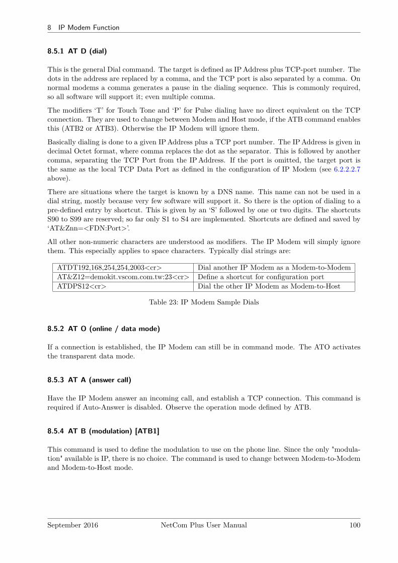
8 IP Modem Function
8.5.1 AT D (dial)
This is the general Dial command. The target is defined as IPAddress plus TCP-port number. Thedots in the address are replaced by a comma, and the TCP port is also separated by a comma. Onnormal modems a comma generates a pause in the dialing sequence. This is commonly required,so all software will support it; even multiple comma.
The modifiers ‘T’ for Touch Tone and ‘P’ for Pulse dialing have no direct equivalent on the TCPconnection. They are used to change between Modem and Host mode, if the ATB command enablesthis (ATB2 or ATB3). Otherwise the IP Modem will ignore them.
Basically dialing is done to a given IPAddress plus a TCP port number. The IPAddress is given indecimal Octet format, where comma replaces the dot as the separator. This is followed by anothercomma, separating the TCP Port from the IPAddress. If the port is omitted, the target port isthe same as the local TCP Data Port as defined in the configuration of IP Modem (see 6.2.2.2.7above).
There are situations where the target is known by a DNS name. This name can not be used in adial string, mostly because very few software will support it. So there is the option of dialing to apre-defined entry by shortcut. This is given by an ‘S’ followed by one or two digits. The shortcutsS90 to S99 are reserved; so far only S1 to S4 are implemented. Shortcuts are defined and saved by‘AT&Znn=<FDN:Port>’.
All other non-numeric characters are understood as modifiers. The IP Modem will simply ignorethem. This especially applies to space characters. Typically dial strings are:
ATDT192,168,254,254,2003<cr> Dial another IP Modem as a Modem-to-ModemAT&Z12=demokit.vscom.com.tw:23<cr> Define a shortcut for configuration portATDPS12<cr> Dial the other IP Modem as Modem-to-Host
Table 23: IP Modem Sample Dials
8.5.2 AT O (online / data mode)
If a connection is established, the IP Modem can still be in command mode. The ATO activatesthe transparent data mode.
8.5.3 AT A (answer call)
Have the IP Modem answer an incoming call, and establish a TCP connection. This command isrequired if Auto-Answer is disabled. Observe the operation mode defined by ATB.
8.5.4 AT B (modulation) [ATB1]
This command is used to define the modulation to use on the phone line. Since the only "modula-tion" available is IP, there is no choice. The command is used to change between Modem-to-Modemand Modem-to-Host mode.
September 2016 NetCom Plus User Manual 100
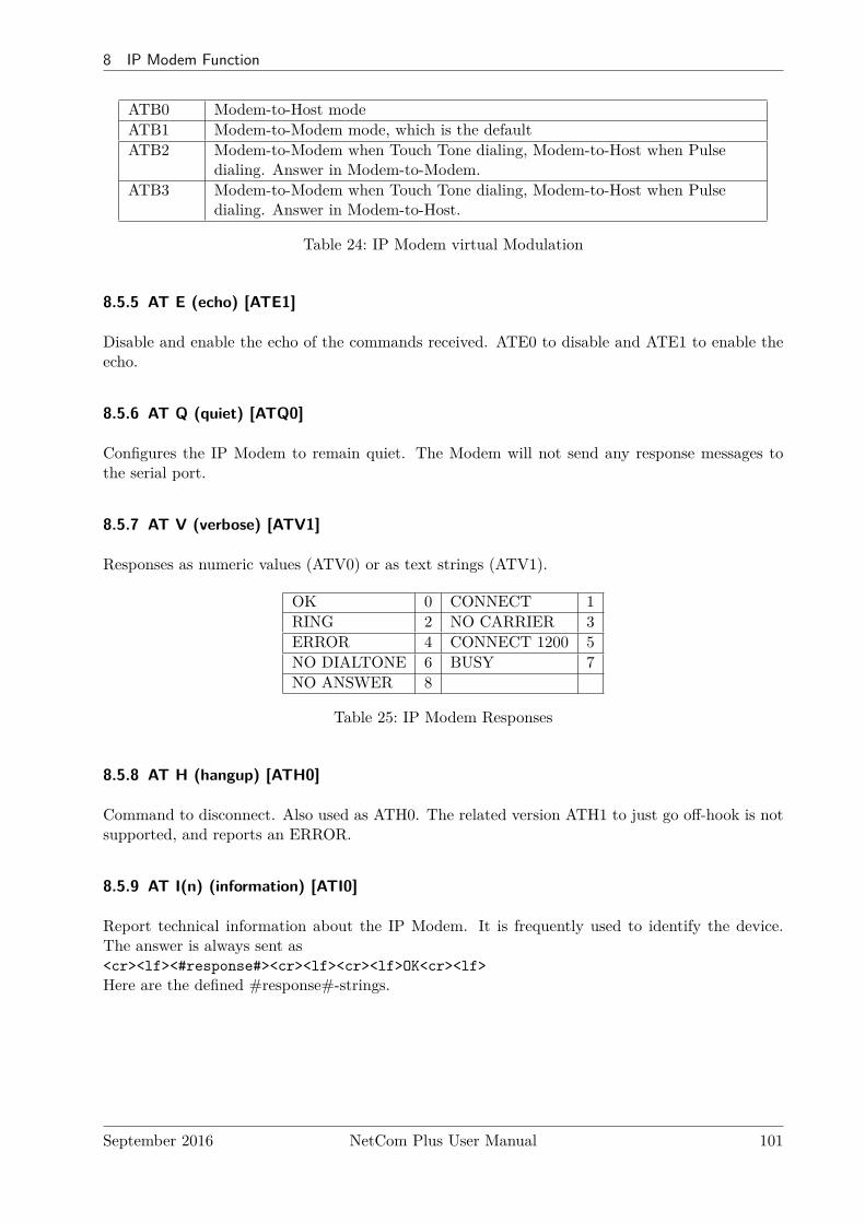
8 IP Modem Function
ATB0 Modem-to-Host modeATB1 Modem-to-Modem mode, which is the defaultATB2 Modem-to-Modem when Touch Tone dialing, Modem-to-Host when Pulse
dialing. Answer in Modem-to-Modem.ATB3 Modem-to-Modem when Touch Tone dialing, Modem-to-Host when Pulse
dialing. Answer in Modem-to-Host.
Table 24: IP Modem virtual Modulation
8.5.5 AT E (echo) [ATE1]
Disable and enable the echo of the commands received. ATE0 to disable and ATE1 to enable theecho.
8.5.6 AT Q (quiet) [ATQ0]
Configures the IP Modem to remain quiet. The Modem will not send any response messages tothe serial port.
8.5.7 AT V (verbose) [ATV1]
Responses as numeric values (ATV0) or as text strings (ATV1).
OK 0 CONNECT 1RING 2 NO CARRIER 3ERROR 4 CONNECT 1200 5NO DIALTONE 6 BUSY 7NO ANSWER 8
Table 25: IP Modem Responses
8.5.8 AT H (hangup) [ATH0]
Command to disconnect. Also used as ATH0. The related version ATH1 to just go off-hook is notsupported, and reports an ERROR.
8.5.9 AT I(n) (information) [ATI0]
Report technical information about the IP Modem. It is frequently used to identify the device.The answer is always sent as<cr><lf><#response#><cr><lf><cr><lf>OK<cr><lf>Here are the defined #response#-strings.
September 2016 NetCom Plus User Manual 101
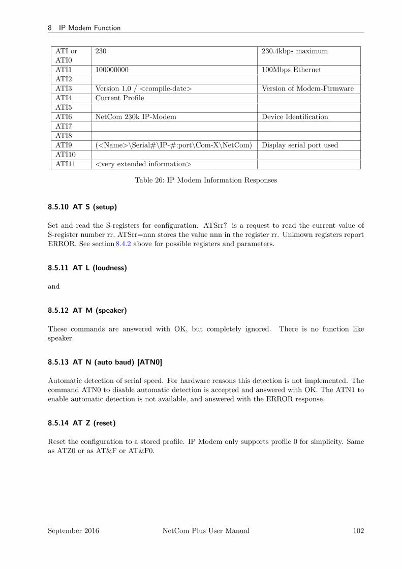
8 IP Modem Function
ATI orATI0
230 230.4kbps maximum
ATI1 100000000 100Mbps EthernetATI2ATI3 Version 1.0 / <compile-date> Version of Modem-FirmwareATI4 Current ProfileATI5ATI6 NetCom 230k IP-Modem Device IdentificationATI7ATI8ATI9 (<Name>\Serial#\IP-#:port\Com-X\NetCom) Display serial port usedATI10ATI11 <very extended information>
Table 26: IP Modem Information Responses
8.5.10 AT S (setup)
Set and read the S-registers for configuration. ATSrr? is a request to read the current value ofS-register number rr, ATSrr=nnn stores the value nnn in the register rr. Unknown registers reportERROR. See section 8.4.2 above for possible registers and parameters.
8.5.11 AT L (loudness)
and
8.5.12 AT M (speaker)
These commands are answered with OK, but completely ignored. There is no function likespeaker.
8.5.13 AT N (auto baud) [ATN0]
Automatic detection of serial speed. For hardware reasons this detection is not implemented. Thecommand ATN0 to disable automatic detection is accepted and answered with OK. The ATN1 toenable automatic detection is not available, and answered with the ERROR response.
8.5.14 AT Z (reset)
Reset the configuration to a stored profile. IP Modem only supports profile 0 for simplicity. Sameas ATZ0 or as AT&F or AT&F0.
September 2016 NetCom Plus User Manual 102
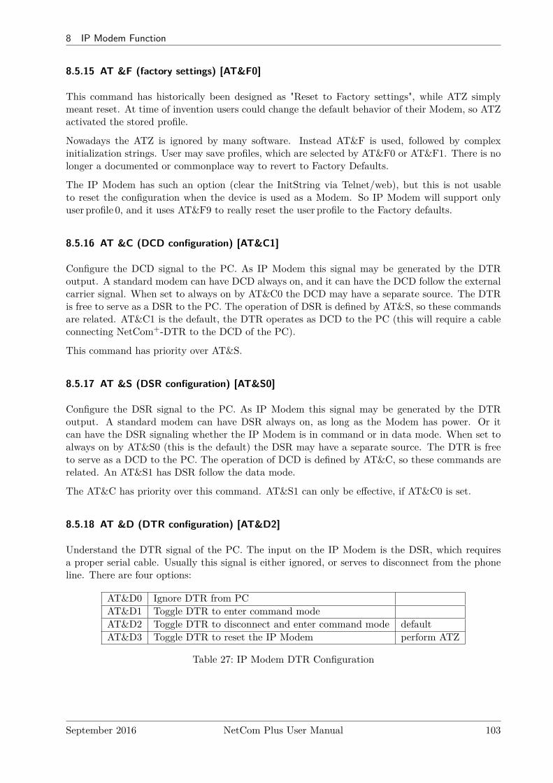
8 IP Modem Function
8.5.15 AT &F (factory settings) [AT&F0]
This command has historically been designed as "Reset to Factory settings", while ATZ simplymeant reset. At time of invention users could change the default behavior of their Modem, so ATZactivated the stored profile.
Nowadays the ATZ is ignored by many software. Instead AT&F is used, followed by complexinitialization strings. User may save profiles, which are selected by AT&F0 or AT&F1. There is nolonger a documented or commonplace way to revert to Factory Defaults.
The IP Modem has such an option (clear the InitString via Telnet/web), but this is not usableto reset the configuration when the device is used as a Modem. So IP Modem will support onlyuser profile 0, and it uses AT&F9 to really reset the user profile to the Factory defaults.
8.5.16 AT &C (DCD configuration) [AT&C1]
Configure the DCD signal to the PC. As IP Modem this signal may be generated by the DTRoutput. A standard modem can have DCD always on, and it can have the DCD follow the externalcarrier signal. When set to always on by AT&C0 the DCD may have a separate source. The DTRis free to serve as a DSR to the PC. The operation of DSR is defined by AT&S, so these commandsare related. AT&C1 is the default, the DTR operates as DCD to the PC (this will require a cableconnecting NetCom+-DTR to the DCD of the PC).
This command has priority over AT&S.
8.5.17 AT &S (DSR configuration) [AT&S0]
Configure the DSR signal to the PC. As IP Modem this signal may be generated by the DTRoutput. A standard modem can have DSR always on, as long as the Modem has power. Or itcan have the DSR signaling whether the IP Modem is in command or in data mode. When set toalways on by AT&S0 (this is the default) the DSR may have a separate source. The DTR is freeto serve as a DCD to the PC. The operation of DCD is defined by AT&C, so these commands arerelated. An AT&S1 has DSR follow the data mode.
The AT&C has priority over this command. AT&S1 can only be effective, if AT&C0 is set.
8.5.18 AT &D (DTR configuration) [AT&D2]
Understand the DTR signal of the PC. The input on the IP Modem is the DSR, which requiresa proper serial cable. Usually this signal is either ignored, or serves to disconnect from the phoneline. There are four options:
AT&D0 Ignore DTR from PCAT&D1 Toggle DTR to enter command modeAT&D2 Toggle DTR to disconnect and enter command mode defaultAT&D3 Toggle DTR to reset the IP Modem perform ATZ
Table 27: IP Modem DTR Configuration
September 2016 NetCom Plus User Manual 103
8 IP Modem Function
8.5.19 AT &K (handshake) [AT&K3]
or as alternative command . . .
8.5.20 AT \Q [AT\Q3]
Configure serial Flow Control. AT&K0 and AT\Q0 disable all Flow Control. The default is AT&K3and AT\Q3 to use RTS/CTS Hardware Flow Control between PC and IP Modem. AT&K4 andAT\Q1 configure for XON/XOFF Software Flow Control between PC and IP Modem. OtherOptions are not supported.
8.5.21 AT &V (view profile)
Show Profiles. This will display the current profile, the stored user profile, the short dial stringsand the factory profile. Parameters are accepted but ignored. AT&V is AT&V0 and is AT&V1.
8.5.22 AT &W (save profile)
Save the current configuration as user profile. AT&W is the same as AT&W0, all other parametersreport an ERROR.
8.5.23 AT &Z (save destination)
This command will save a destination in Internet syntax. It is given by <host>:<port>. The<host> is either an IPAddress in dotted octet notation, or an FQN in correct syntax. The <port>is a string representing a decimal number. If :<port> is omitted, the target port is the local TCPData Port as defined in the configuration of IP Modem (see 6.2.2.2.7 above).
September 2016 NetCom Plus User Manual 104
9 Print Server Operation
9 Print Server Operation
Sometimes the Serial Device Servers are used together with serial printers. These printers areavailable via a network to several stations for printing. So far there have been two operation modesto achieve this. First the serial port can operate as a TCP Raw Server, and the station just sendsthe data to print via a TCP connection. As second option a computer running Windows couldinstall the driver for virtual serial ports. The printer is then controlled via this Com port. Inboth these solutions the buffering of data occurred on the client station. Beginning with Firmwareversion 2.2 the NetCom+ Devices offer a true Print Server mode, using the Line Printer Daemonprotocol as of RFC1197. Here a print server (lpd) is a station with one IPAddress and a singledefined port to accept commands and data for printing. Several printers may be attached to theprint server. Each printer has a separate data queue for management of print jobs. The data ofthe jobs is saved in this queue, instead of the client as before.
9.1 Printer Queue
The basic function of an lpd is to accept the data for printing, store it in a spooler queue, andsend it to the printer when this is ready for printing. This is done for several queues in parallel.Each printer is identified by the name of the queue, where it is attached to. The NetCom+ DeviceServers allow to configure a custom name for each queue, while the default name is »lpd« plus thenumber of the serial port (lpd1, lpd2, . . . ). This name is set in the properties of the serial port.When the lpd is running on a separate computer, the hard disk is used to save the data of thequeues. The NetCom+ Servers neither have a mass storage device, nor huge amounts of memory.Each queue accepts at least one job with a size of up to 250 KB print data. If the job has moredata, memory is either assigned dynamically to save the job, or the data is spooled through a ringbuffer. Data is printed while the client still sends data. The amount of available dynamic memorydepends on the number of ports in a NetCom+ Device Server, and the operations active on theseports.
9.2 Printer Reset
Before a new job is sent to the printer, this printer should be in a well known state. On a parallelprinter port this is easy to achieve. There is a defined signal to send a »reset« command to theprinter.
Such a definition is not available for serial printers. Instead there is a reset command, which usersmay send via the serial line. Typically this command is specific to the manufacturer or even tothe printer model. So the NetCom+ allows to specify this command by entering an ‘InitString’ foreach queue.
9.2.1 Init String Definition
The Initialization of the printer typically involves ASCII control codes, ordinary ASCII charactersand some binary data. On some models it may also be necessary to provide a certain state ofthe modem control signals RTS and DTR, applied with special timing. The ‘InitString’ in theNetCom+ Device Serves offer all these options.
September 2016 NetCom Plus User Manual 105
9 Print Server Operation
9.2.1.1 ASCII Text Ordinary ASCII characters are entered as they are on the keyboard. Thesingle exception is the ’Less Than’ character ’<’, which is used for other special functions.
9.2.1.2 ASCII Control Codes ASCII control codes are entered by their standard name, enclosedin ’Angle Brackets’, i.e. in ’<’ and ’>’ (Greater Than). Some examples of this are <ESC>, <CR>or <TAB>.
9.2.1.3 Numeric Codes Especially binary data must be sent by means of its numeric value. Sincethe ’<’ ASCII character has a special function, the only way to use this is the numeric method.This also applies to printable characters of some Extended ASCII character sets.
The NetCom+ accept the decimal value, also enclosed in angle brackets. Up to three decimal digitsdefine the character to send to the printer. The ’<’ is used as <60>, while the <ESC> may alsosent as <027>. The ’>’ may be used directly, however for clarity <62> should be preferred.
9.2.1.4 Modem Control Signals Via the ‘InitString’ control of RTS and DTR is available. Thismanual does not make statements about voltage levels on the signals, these are just set to an activeor inactive state. <RTS+> and <RTS-> activate and deactivate the RTS signal, while <DTR+>and <DTR-> do the same for DTR.
9.2.1.5 Timing Options Especially when using Modem Control signals it will be required to holdthem in a given state for a defined amount of time. This may be done by applying a »Pause«-command in the ‘InitString’. The delay is given as numeric value in milliseconds (msec), precededby a ‘P’. So <P50> causes the NetCom+ to wait 50 msec before proceeding with the next commandor start printing. Up to three digits are possible. If more than 999 msec are required, the Pause-command must be repeated.
Please note: The delay is not executed as an exact time. NetCom+ guarantees to wait at least therequired amount of time. The smallest delay possible is 10 msec, due to internal handling of dateand time.
9.2.2 Reset Example
For example here is a hypothetical serial printer. The serial port operates at 1200 bps, 7 bit andeven parity and 1 stop bit. For Reset the printer requires the command "<ESC>@0" sent withDTR and RTS off. When the data is transmitted, DTR must be on, and 50 msec later RTS mustalso be on.
Each character sent is 10 bits long, including the start bit. At 1200 bps each character needs8.3msec for transmission. So the transmission lasts for 25 msec. To be sure the control signals areinactive, an extra delay is applied after change of signals. The resulting string would be <RTS-><DTR-><P10><ESC>@0<P35><DTR+><P50><RTS+> The delay of 35 msec after thecommand string "<ESC>@0" shall ensure, all data is completely transmitted to the printer.
September 2016 NetCom Plus User Manual 106
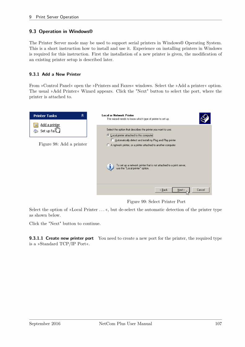
9 Print Server Operation
9.3 Operation in Windows®
The Printer Server mode may be used to support serial printers in Windows® Operating System.This is a short instruction how to install and use it. Experience on installing printers in Windowsis required for this instruction. First the installation of a new printer is given, the modification ofan existing printer setup is described later.
9.3.1 Add a New Printer
From »Control Panel« open the »Printers and Faxes« windows. Select the »Add a printer« option.The usual »Add Printer« Wizard appears. Click the "Next" button to select the port, where theprinter is attached to.
Figure 98: Add a printer
Figure 99: Select Printer Port
Select the option of »Local Printer . . . «, but de-select the automatic detection of the printer typeas shown below.
Click the "Next" button to continue.
9.3.1.1 Create new printer port You need to create a new port for the printer, the required typeis a »Standard TCP/IP Port«.
September 2016 NetCom Plus User Manual 107
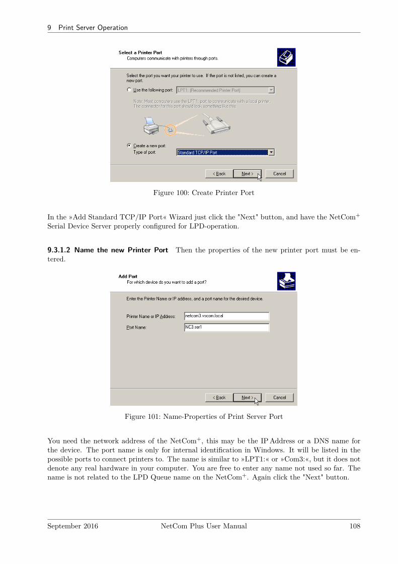
9 Print Server Operation
Figure 100: Create Printer Port
In the »Add Standard TCP/IP Port« Wizard just click the "Next" button, and have the NetCom+
Serial Device Server properly configured for LPD-operation.
9.3.1.2 Name the new Printer Port Then the properties of the new printer port must be en-tered.
Figure 101: Name-Properties of Print Server Port
You need the network address of the NetCom+, this may be the IPAddress or a DNS name forthe device. The port name is only for internal identification in Windows. It will be listed in thepossible ports to connect printers to. The name is similar to »LPT1:« or »Com3:«, but it does notdenote any real hardware in your computer. You are free to enter any name not used so far. Thename is not related to the LPD Queue name on the NetCom+. Again click the "Next" button.
September 2016 NetCom Plus User Manual 108
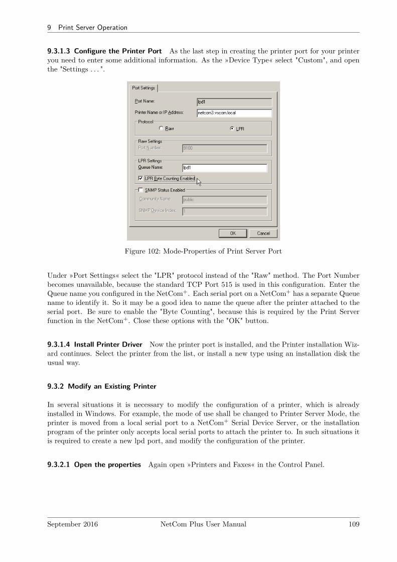
9 Print Server Operation
9.3.1.3 Configure the Printer Port As the last step in creating the printer port for your printeryou need to enter some additional information. As the »Device Type« select "Custom", and openthe "Settings . . . ".
Figure 102: Mode-Properties of Print Server Port
Under »Port Settings« select the "LPR" protocol instead of the "Raw" method. The Port Numberbecomes unavailable, because the standard TCP Port 515 is used in this configuration. Enter theQueue name you configured in the NetCom+. Each serial port on a NetCom+ has a separate Queuename to identify it. So it may be a good idea to name the queue after the printer attached to theserial port. Be sure to enable the "Byte Counting", because this is required by the Print Serverfunction in the NetCom+. Close these options with the "OK" button.
9.3.1.4 Install Printer Driver Now the printer port is installed, and the Printer installation Wiz-ard continues. Select the printer from the list, or install a new type using an installation disk theusual way.
9.3.2 Modify an Existing Printer
In several situations it is necessary to modify the configuration of a printer, which is alreadyinstalled in Windows. For example, the mode of use shall be changed to Printer Server Mode, theprinter is moved from a local serial port to a NetCom+ Serial Device Server, or the installationprogram of the printer only accepts local serial ports to attach the printer to. In such situations itis required to create a new lpd port, and modify the configuration of the printer.
9.3.2.1 Open the properties Again open »Printers and Faxes« in the Control Panel.
September 2016 NetCom Plus User Manual 109
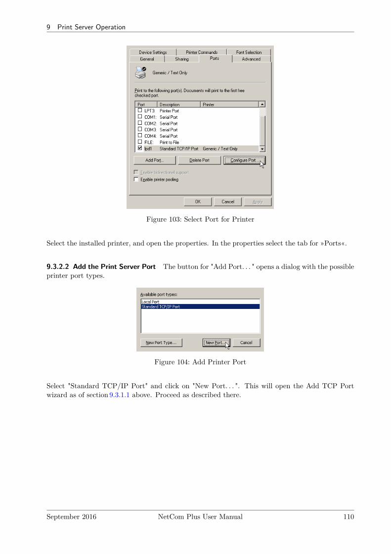
9 Print Server Operation
Figure 103: Select Port for Printer
Select the installed printer, and open the properties. In the properties select the tab for »Ports«.
9.3.2.2 Add the Print Server Port The button for "Add Port. . . " opens a dialog with the possibleprinter port types.
Figure 104: Add Printer Port
Select "Standard TCP/IP Port" and click on "New Port. . . ". This will open the Add TCP Portwizard as of section 9.3.1.1 above. Proceed as described there.
September 2016 NetCom Plus User Manual 110
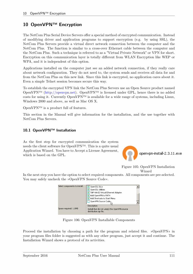
10 OpenVPN™ Encryption
10 OpenVPN™ Encryption
The NetCom Plus Serial Device Servers offer a special method of encrypted communication. Insteadof modifying driver and application programs to support encryption (e.g. by using SSL), theNetCom Plus Servers provide a virtual direct network connection between the computer and theNetCom Plus. The function is similar to a cross-over Ethernet cable between the computer andthe NetCom Plus. Such a technique is referred to as a "Virtual Private Network" or VPN for short.Encryption on this communication layer is totally different from WLAN Encryption like WEP orWPA, and it is independent of this option.
Applications installed on the computer just see an added network connection, if they really careabout network configuration. They do not need to, the system sends and receives all data for andfrom the NetCom Plus on this new link. Since this link is encrypted, no application cares about it.Even a simple Telnet session becomes secure this way.
To establish the encrypted VPN link the NetCom Plus Servers use an Open Source product namedOpenVPN™ (http://openvpn.net). OpenVPN™ is licensed under GPL, hence there is no addedcosts for using it. Currently OpenVPN™ is available for a wide range of systems, including Linux,Windows 2000 and above, as well as Mac OS X.
OpenVPN™ is a product full of features.
This section in the Manual will give information for the installation, and the use together withNetCom Plus Servers.
10.1 OpenVPN™ Installation
Figure 105: OpenVPN InstallationWizard
As the first step for encrypted communication the systemneeds the client software for OpenVPN™. This is a quite usualApplication Wizard. You have to Accept a License Agreement,which is based on the GPL.
In the next step you have the option to select required components. All components are pre-selected.You may safely uncheck the »OpenVPN Source Code«.
Figure 106: OpenVPN Installable Components
Proceed the installation by choosing a path for the program and related files. »OpenVPN« inyour program files folder is suggested as with any other program, just accept it and continue. TheInstallation Wizard shows a protocol of its activities.
September 2016 NetCom Plus User Manual 111
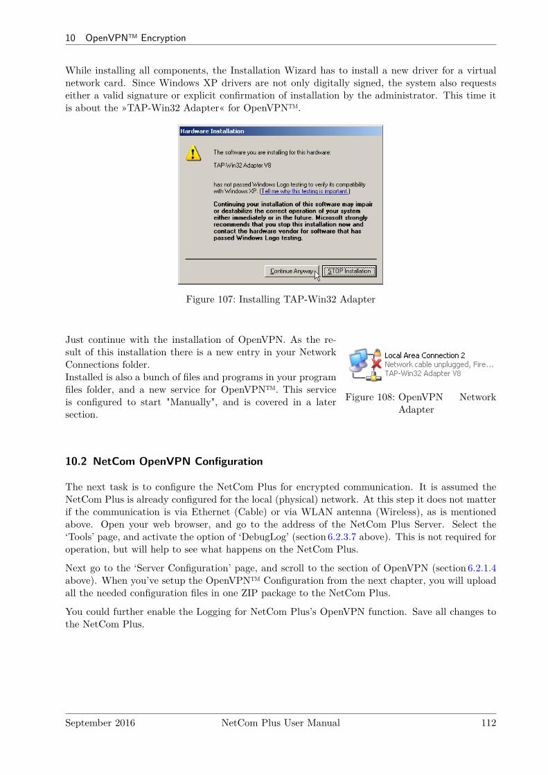
10 OpenVPN™ Encryption
While installing all components, the Installation Wizard has to install a new driver for a virtualnetwork card. Since Windows XP drivers are not only digitally signed, the system also requestseither a valid signature or explicit confirmation of installation by the administrator. This time itis about the »TAP-Win32 Adapter« for OpenVPN™.
Figure 107: Installing TAP-Win32 Adapter
Figure 108: OpenVPN NetworkAdapter
Just continue with the installation of OpenVPN. As the re-sult of this installation there is a new entry in your NetworkConnections folder.Installed is also a bunch of files and programs in your programfiles folder, and a new service for OpenVPN™. This serviceis configured to start "Manually", and is covered in a latersection.
10.2 NetCom OpenVPN Configuration
The next task is to configure the NetCom Plus for encrypted communication. It is assumed theNetCom Plus is already configured for the local (physical) network. At this step it does not matterif the communication is via Ethernet (Cable) or via WLAN antenna (Wireless), as is mentionedabove. Open your web browser, and go to the address of the NetCom Plus Server. Select the‘Tools’ page, and activate the option of ‘DebugLog’ (section 6.2.3.7 above). This is not required foroperation, but will help to see what happens on the NetCom Plus.
Next go to the ‘Server Configuration’ page, and scroll to the section of OpenVPN (section 6.2.1.4above). When you’ve setup the OpenVPN™ Configuration from the next chapter, you will uploadall the needed configuration files in one ZIP package to the NetCom Plus.
You could further enable the Logging for NetCom Plus’s OpenVPN function. Save all changes tothe NetCom Plus.
September 2016 NetCom Plus User Manual 112
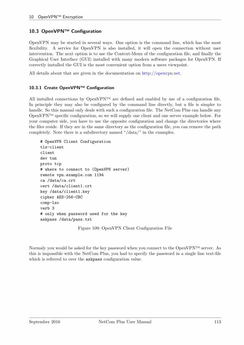
10 OpenVPN™ Encryption
10.3 OpenVPN™ Configuration
OpenVPN may be started in several ways. One option is the command line, which has the mostflexibility. A service for OpenVPN is also installed, it will open the connection without userintervention. The next option is to use the Context-Menu of the configuration file, and finally theGraphical User Interface (GUI) installed with many modern software packages for OpenVPN. Ifcorrectly installed the GUI is the most convenient option from a users viewpoint.
All details about that are given in the documentation on http://openvpn.net.
10.3.1 Create OpenVPN™ Configuration
All installed connections by OpenVPN™ are defined and enabled by use of a configuration file.In principle they may also be configured by the command line directly, but a file is simpler tohandle. So this manual only deals with such a configuration file. The NetCom Plus can handle anyOpenVPN™ specific configuration, so we will supply one client and one server example below. Foryour computer side, you have to use the opposite configuration and change the directories wherethe files reside. If they are in the same directory as the configuration file, you can remove the pathcompletely. Note there is a subdirectory named “/data/” in the examples.
# OpenVPN Client Configurationtls-clientclientdev tunproto tcp# where to connect to (OpenVPN server)remote vpn.example.com 1194ca /data/ca.crtcert /data/client1.crtkey /data/client1.keycipher AES-256-CBCcomp-lzoverb 3# only when password used for the keyaskpass /data/pass.txt
Figure 109: OpenVPN Client Configuration File
Normaly you would be asked for the key password when you connect to the OpenVPN™ server. Asthis is impossible with the NetCom Plus, you had to specify the password in a single line text-filewhich is referred to over the askpass configuration value.
September 2016 NetCom Plus User Manual 113
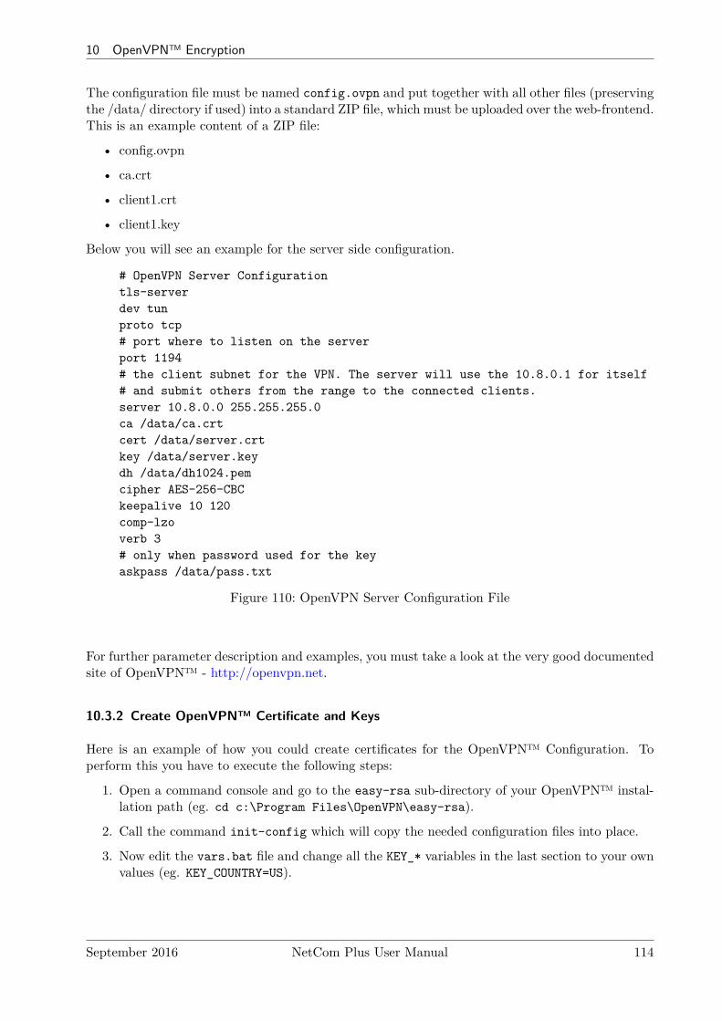
10 OpenVPN™ Encryption
The configuration file must be named config.ovpn and put together with all other files (preservingthe /data/ directory if used) into a standard ZIP file, which must be uploaded over the web-frontend.This is an example content of a ZIP file:
• config.ovpn
• ca.crt
• client1.crt
• client1.key
Below you will see an example for the server side configuration.
# OpenVPN Server Configurationtls-serverdev tunproto tcp# port where to listen on the serverport 1194# the client subnet for the VPN. The server will use the 10.8.0.1 for itself# and submit others from the range to the connected clients.server 10.8.0.0 255.255.255.0ca /data/ca.crtcert /data/server.crtkey /data/server.keydh /data/dh1024.pemcipher AES-256-CBCkeepalive 10 120comp-lzoverb 3# only when password used for the keyaskpass /data/pass.txt
Figure 110: OpenVPN Server Configuration File
For further parameter description and examples, you must take a look at the very good documentedsite of OpenVPN™ - http://openvpn.net.
10.3.2 Create OpenVPN™ Certificate and Keys
Here is an example of how you could create certificates for the OpenVPN™ Configuration. Toperform this you have to execute the following steps:
1. Open a command console and go to the easy-rsa sub-directory of your OpenVPN™ instal-lation path (eg. cd c:\Program Files\OpenVPN\easy-rsa).
2. Call the command init-config which will copy the needed configuration files into place.
3. Now edit the vars.bat file and change all the KEY_* variables in the last section to your ownvalues (eg. KEY_COUNTRY=US).
September 2016 NetCom Plus User Manual 114

10 OpenVPN™ Encryption
4. Call the commands vars.bat, clean-all and build-ca in this order. You could press enterfor all the values for which you will be asked, except the Common Name, which should be thename of your VPN (eg. MyVPN).
5. The next command build-key-server server will generate a certificate and private key forthe server. As before, you could leave the values on the defaults but should enter the CommonName (eg. MyServer). The password field could be blank or set for enhanced security. Thelast two questions must be answered with Yes (’y’).
6. Now you can create as many keys as you want for your clients with build-key client1,build-key client2, .... Enter the client name from the command line for Common Name(eg. client1). The other values are the same as with the step before.
7. Finally call build-dh to generate Diffie-Hellman parameters for the OpenVPN™ server.
8. Now you find the certificates and keys in the subdirectory keys. You will use these files tocreate a config ZIP container for the NetCom Plus as described before or use them on yourcomputer and copy these files with the config file (eg. client1.ovpn) into the config directoryof OpenVPN™.
10.3.3 Start NetCom Plus with OpenVPN™ active
This is the moment to open the web browser again, and access the Server Configuration of theNetCom Plus. Go to the OpenVPN Parameter section (figure 65), and carefully double check allvalues. They must match the example used here. If you are sure, change the first parameter‘OpenVPN’ from “Disabled” to “Server”. Save the changes, and let the NetCom Plus perform itsReboot. After some time your web browser will attempt to open the Server Configuration pageagain, but this will fail. This is desired, because now the communication must be done encrypted.The NetCom Plus is still sending answers to PING on the Ethernet (or WLAN), and it will alsoaccept a TCP connection for Debugging on Port 1200. Try it by opening a Telnet session toPort 1200. And finally the NetCom Plus waits for a TCP connection on Port 1194, to establish alink via OpenVPN
10.3.4 Start OpenVPN™ by Context-Menu
The Graphical User Interface (GUI) is pretty much intuitive, so it is not covered in this manual.Instead the other graphical option is documented now.
The Installation Wizard of OpenVPN™ associated the ".ovpn" file type with Notepad to open bydouble click. It also added an action available via the Context-Menu of the file.
September 2016 NetCom Plus User Manual 115
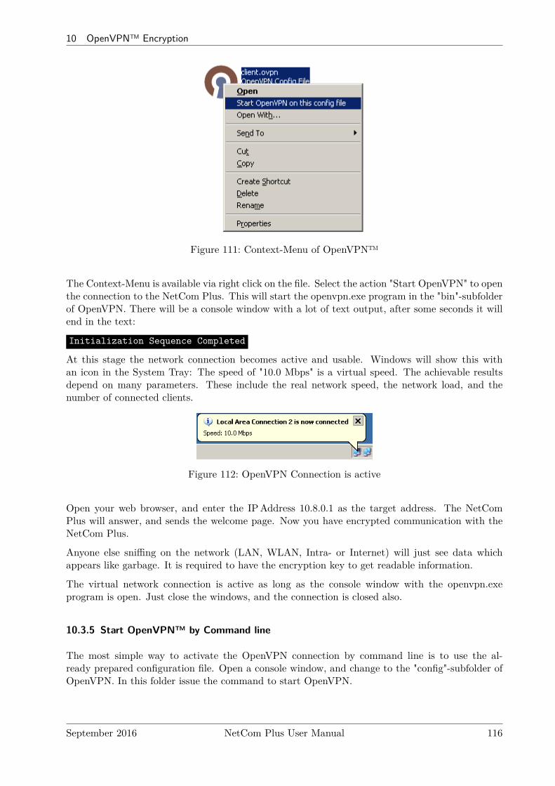
10 OpenVPN™ Encryption
Figure 111: Context-Menu of OpenVPN™
The Context-Menu is available via right click on the file. Select the action "Start OpenVPN" to openthe connection to the NetCom Plus. This will start the openvpn.exe program in the "bin"-subfolderof OpenVPN. There will be a console window with a lot of text output, after some seconds it willend in the text:
Initialization Sequence Completed
At this stage the network connection becomes active and usable. Windows will show this withan icon in the System Tray: The speed of "10.0 Mbps" is a virtual speed. The achievable resultsdepend on many parameters. These include the real network speed, the network load, and thenumber of connected clients.
Figure 112: OpenVPN Connection is active
Open your web browser, and enter the IPAddress 10.8.0.1 as the target address. The NetComPlus will answer, and sends the welcome page. Now you have encrypted communication with theNetCom Plus.
Anyone else sniffing on the network (LAN, WLAN, Intra- or Internet) will just see data whichappears like garbage. It is required to have the encryption key to get readable information.
The virtual network connection is active as long as the console window with the openvpn.exeprogram is open. Just close the windows, and the connection is closed also.
10.3.5 Start OpenVPN™ by Command line
The most simple way to activate the OpenVPN connection by command line is to use the al-ready prepared configuration file. Open a console window, and change to the "config"-subfolder ofOpenVPN. In this folder issue the command to start OpenVPN.
September 2016 NetCom Plus User Manual 116
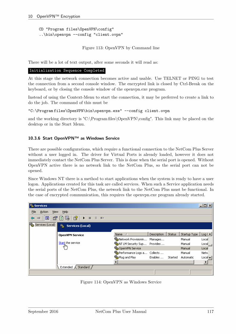
10 OpenVPN™ Encryption
CD "Program files\OpenVPN\config"..\bin\openvpn --config "client.ovpn"
Figure 113: OpenVPN by Command line
There will be a lot of text output, after some seconds it will read as:
Initialization Sequence Completed
At this stage the network connection becomes active and usable. Use TELNET or PING to testthe connection from a second console window. The encrypted link is closed by Ctrl-Break on thekeyboard, or by closing the console window of the openvpn.exe program.
Instead of using the Context-Menu to start the connection, it may be preferred to create a link todo the job. The command of this must be
"C:\Program files\OpenVPN\bin\openvpn.exe" --config client.ovpn
and the working directory is "C:\Programfiles\OpenVPN\config". This link may be placed on thedesktop or in the Start Menu.
10.3.6 Start OpenVPN™ as Windows Service
There are possible configurations, which require a functional connection to the NetCom Plus Serverwithout a user logged in. The driver for Virtual Ports is already loaded, however it does notimmediately contact the NetCom Plus Server. This is done when the serial port is opened. WithoutOpenVPN active there is no network link to the NetCom Plus, so the serial port can not beopened.
Since Windows NT there is a method to start applications when the system is ready to have a userlogon. Applications created for this task are called services. When such a Service application needsthe serial ports of the NetCom Plus, the network link to the NetCom Plus must be functional. Inthe case of encrypted communication, this requires the openvpn.exe program already started.
Figure 114: OpenVPN as Windows Service
September 2016 NetCom Plus User Manual 117
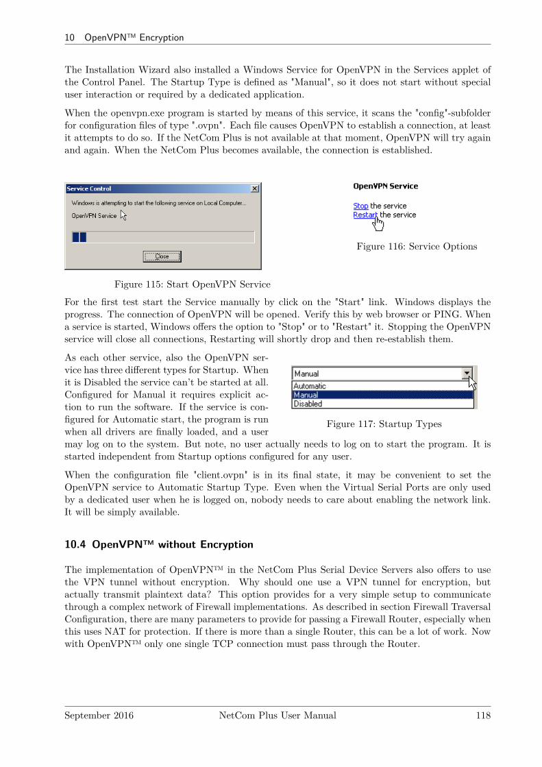
10 OpenVPN™ Encryption
The Installation Wizard also installed a Windows Service for OpenVPN in the Services applet ofthe Control Panel. The Startup Type is defined as "Manual", so it does not start without specialuser interaction or required by a dedicated application.
When the openvpn.exe program is started by means of this service, it scans the "config"-subfolderfor configuration files of type ".ovpn". Each file causes OpenVPN to establish a connection, at leastit attempts to do so. If the NetCom Plus is not available at that moment, OpenVPN will try againand again. When the NetCom Plus becomes available, the connection is established.
Figure 115: Start OpenVPN Service
Figure 116: Service Options
For the first test start the Service manually by click on the "Start" link. Windows displays theprogress. The connection of OpenVPN will be opened. Verify this by web browser or PING. Whena service is started, Windows offers the option to "Stop" or to "Restart" it. Stopping the OpenVPNservice will close all connections, Restarting will shortly drop and then re-establish them.
Figure 117: Startup Types
As each other service, also the OpenVPN ser-vice has three different types for Startup. Whenit is Disabled the service can’t be started at all.Configured for Manual it requires explicit ac-tion to run the software. If the service is con-figured for Automatic start, the program is runwhen all drivers are finally loaded, and a usermay log on to the system. But note, no user actually needs to log on to start the program. It isstarted independent from Startup options configured for any user.
When the configuration file "client.ovpn" is in its final state, it may be convenient to set theOpenVPN service to Automatic Startup Type. Even when the Virtual Serial Ports are only usedby a dedicated user when he is logged on, nobody needs to care about enabling the network link.It will be simply available.
10.4 OpenVPN™ without Encryption
The implementation of OpenVPN™ in the NetCom Plus Serial Device Servers also offers to usethe VPN tunnel without encryption. Why should one use a VPN tunnel for encryption, butactually transmit plaintext data? This option provides for a very simple setup to communicatethrough a complex network of Firewall implementations. As described in section Firewall TraversalConfiguration, there are many parameters to provide for passing a Firewall Router, especially whenthis uses NAT for protection. If there is more than a single Router, this can be a lot of work. Nowwith OpenVPN™ only one single TCP connection must pass through the Router.
September 2016 NetCom Plus User Manual 118
10 OpenVPN™ Encryption
The configuration is much more simple, the Router does not need to have a lot of detailed data.All the different connections required between the Client computer and the NetCom Plus to usethe Serial Device Server are carried via this single OpenVPN™ connection in TCP mode. WhenOpenVPN™ is used this way, probably there is no need for an extra protection by encryption.An encryption of “None” obviously saves computation resources (i.e. performance) on the NetComPlus and on the Client computer.
10.5 Reconfigure Virtual Serial Ports for OpenVPN™
It may often happen the NetCom Plus is already installed and tested. In this process typicallythe drivers for Virtual Com Ports are also installed, configured and tested. Now the situation mayoccur where encryption is a demand. The change of installation is a rather simple process.
First install and test the encrypted connection via OpenVPN™, as described above. Now theVirtual Com Ports are no longer accessible, because this function is blocked on the IPAddressused on the standard network connection (Ethernet/WLAN). It is only available on the IPAddressprovided by OpenVPN™ protocol.
To the driver installation this is the same situation as if the normal IPAddress has changed. Theconfiguration requires a change as documented in section 4.4.5.1 about changed IPAddress. Proceedas described there, and then use the Virtual Com Ports via the encrypted link.
September 2016 NetCom Plus User Manual 119
11 viaVPN Remote Access System
11 viaVPN Remote Access System
The paragraph 6.2.1.5 on page 68 mentions the option of viaVPN. Since this is only available insome models of NetCom Plus, the description of this system is delegated to this chapter entirely.
11.1 Obstacles when used via Internet
When a NetCom Plus is used via the Internet, it requires a public IPAddress or at least someconfiguration of the Firewall at the location of the NetCom+. Both options allow Access from anyPC to the NetCom+, but in some networks this is not possible for various reasons. Examples forthis often include mobile communication networks by 3G or 4G functions.
Assuming such configuration is not possible, then the NetCom Plus must somehow connect to thePC, operating as a client. That would restrict the function to TCP Raw Client or UDP Mode.And this way of operation also requires similar network configuration, now at the location of theTarget PC. Even more only one PC can be specified as target.
To have full access to the functions of NetCom Plus - including the Driver Mode - the PC mightoperate as a Server for OpenVPN. If the PC provides access to it via public Internet, the NetCom+
may establish a connection using OpenVPN (see chapter 10 on page 111). On this protectednetwork there is no problem to use all functions of a NetCom+. But this still requires networkconfiguration at the PC location.
As a second option using OpenVPN the user PC and the NetCom Plus may connect to a privateserver for OpenVPN. Then there is no need to have special network configuration at the NetCom+
or at the PC, since typical configurations allow such an access by default. But in this case the userhas to provide the private server for OpenVPN. It must be available in public Internet, this is alsonot very easy.
The downside of OpenVPN is the limited access, configured for security. Either you operate theNetCom Plus via the local network (LAN), or via OpenVPN. In the second way you have to useOpenVPN not only for remote access, but for local access also.
11.2 How viaVPN solves the above Issues
The viaVPN system provides the necessary tools and components to circumvent the obstaclesmentioned above. It provides a server available in public Internet, both the NetCom Plus andthe Client PC connect to this. Therefore it is named as “Rendezvous Server”, where both meet.The NetCom+ provides special configuration, which is firewall-friendly and enables the connectionto the Rendezvous Server. Likewise the PC uses a Client Utility, this allows connection to theRendezvous Server also in a convenient and firewall-friendly manner.The customer manages all his NetCom Plus via a web-based account, i.e. via his browser.
The connection from the NetCom+ to the Rendezvous Server is in parallel to the normal operationon the LAN. This allows client PCs on the LAN to operate the NetCom+ in the same way aswithout the viaVPN system. And other Client PCs via the Internet can also access the NetCom+
without breaking the operation on the LAN. In particular, if the Client PC is a mobile device(typically a Laptop), this PC can operate the NetCom+ directly in the LAN, and via the ClientUtility while the PC is far away (road warrior mode).
September 2016 NetCom Plus User Manual 120
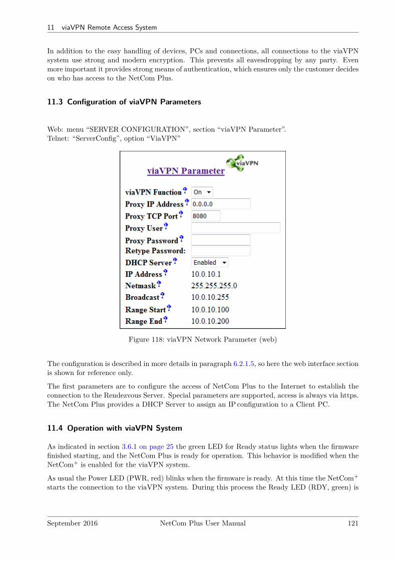
11 viaVPN Remote Access System
In addition to the easy handling of devices, PCs and connections, all connections to the viaVPNsystem use strong and modern encryption. This prevents all eavesdropping by any party. Evenmore important it provides strong means of authentication, which ensures only the customer decideson who has access to the NetCom Plus.
11.3 Configuration of viaVPN Parameters
Web: menu “SERVER CONFIGURATION”, section “viaVPN Parameter”.Telnet: “ServerConfig”, option “ViaVPN”
Figure 118: viaVPN Network Parameter (web)
The configuration is described in more details in paragraph 6.2.1.5, so here the web interface sectionis shown for reference only.
The first parameters are to configure the access of NetCom Plus to the Internet to establish theconnection to the Rendezvous Server. Special parameters are supported, access is always via https.The NetCom Plus provides a DHCP Server to assign an IP configuration to a Client PC.
11.4 Operation with viaVPN System
As indicated in section 3.6.1 on page 25 the green LED for Ready status lights when the firmwarefinished starting, and the NetCom Plus is ready for operation. This behavior is modified when theNetCom+ is enabled for the viaVPN system.
As usual the Power LED (PWR, red) blinks when the firmware is ready. At this time the NetCom+
starts the connection to the viaVPN system. During this process the Ready LED (RDY, green) is
September 2016 NetCom Plus User Manual 121

11 viaVPN Remote Access System
not just on, instead it blinks in a slow pace (symmetric On and Off). When the connection to theRendezvous Server is established, the Ready LED is permanent On.
When a Client PC is connected via the Utility, this is also signaled by the Ready LED. This timethe LED light is interrupted (short time Off, most time On).
Power LED Ready LED StatusOff Device off, no powerOn Off Firmware startupOn Symmetric Blink Start connection to viaVPNOn On Connection to viaVPN establishedOn Interrupted Client PC connected to device
Table 28: Ready LED with viaVPN
September 2016 NetCom Plus User Manual 122
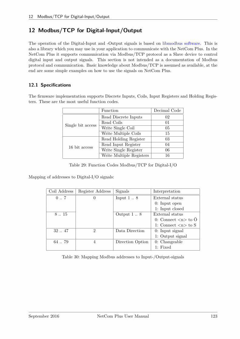
12 Modbus/TCP for Digital-Input/Output
12 Modbus/TCP for Digital-Input/Output
The operation of the Digital-Input and -Output signals is based on libmodbus software. This isalso a library which you may use in your application to communicate with the NetCom Plus. In theNetCom Plus it supports communication via Modbus/TCP protocol as a Slave device to controldigital input and output signals. This section is not intended as a documentation of Modbusprotocol and communication. Basic knowledge about Modbus/TCP is assumed as available, at theend are some simple examples on how to use the signals on NetCom Plus.
12.1 Specifications
The firmware implementation supports Discrete Inputs, Coils, Input Registers and Holding Regis-ters. These are the most useful function codes.
Function Decimal Code
Single bit access
Read Discrete Inputs 02Read Coils 01Write Single Coil 05Write Multiple Coils 15
16 bit access
Read Holding Register 03Read Input Register 04Write Single Register 06Write Multiple Registers 16
Table 29: Function Codes Modbus/TCP for Digital-I/O
Mapping of addresses to Digital-I/O signals:
Coil Address Register Address Signals Interpretation0 .. 7 0 Input 1 .. 8 External status
0: Input open1: Input closed
8 .. 15 Output 1 .. 8 External status0: Connect <n> to Ö1: Connect <n> to S
32 .. 47 2 Data Direction 0: Input signal1: Output signal
64 .. 79 4 Direction Option 0: Changeable1: Fixed
Table 30: Mapping Modbus addresses to Input-/Output-signals
September 2016 NetCom Plus User Manual 123
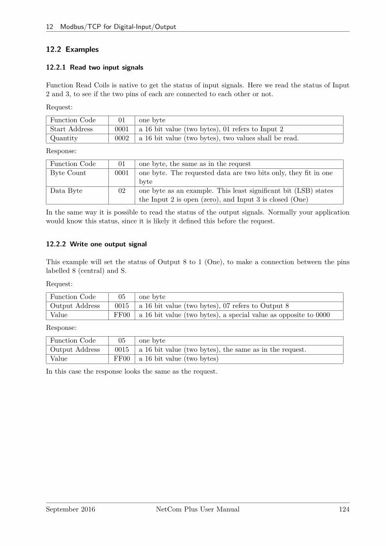
12 Modbus/TCP for Digital-Input/Output
12.2 Examples
12.2.1 Read two input signals
Function Read Coils is native to get the status of input signals. Here we read the status of Input2 and 3, to see if the two pins of each are connected to each other or not.
Request:
Function Code 01 one byteStart Address 0001 a 16 bit value (two bytes), 01 refers to Input 2Quantity 0002 a 16 bit value (two bytes), two values shall be read.
Response:
Function Code 01 one byte, the same as in the requestByte Count 0001 one byte. The requested data are two bits only, they fit in one
byteData Byte 02 one byte as an example. This least significant bit (LSB) states
the Input 2 is open (zero), and Input 3 is closed (One)
In the same way it is possible to read the status of the output signals. Normally your applicationwould know this status, since it is likely it defined this before the request.
12.2.2 Write one output signal
This example will set the status of Output 8 to 1 (One), to make a connection between the pinslabelled 8 (central) and S.
Request:
Function Code 05 one byteOutput Address 0015 a 16 bit value (two bytes), 07 refers to Output 8Value FF00 a 16 bit value (two bytes), a special value as opposite to 0000
Response:
Function Code 05 one byteOutput Address 0015 a 16 bit value (two bytes), the same as in the request.Value FF00 a 16 bit value (two bytes)
In this case the response looks the same as the request.
September 2016 NetCom Plus User Manual 124
13 TCP/IP Description
13 TCP/IP Description
TCP/IP is the protocol used on the Internet, and in local networks as well. This opens access toany device connected somewhere to the Internet. But a simple contact like plugging in a cable isnot enough. The network has to be configured. Your network administrator is responsible to dothat. If any question during configuration, ask him. Configuration means to set certain parametersin any device and computer.
Since IP-configuration is a frequent source of problems, a little bit of theory is provided here.
13.1 Recommended Settings
Basically every device on the LAN has a so-called IPAddress. In typical small networks theIPAddress is similar to 192.168.X.Y, and there is a corresponding netmask of 255.255.255.0. TheX ranges from 0 to 255, while Y is from 1 to 254. The combination of X.Y must be unique in yourLAN, i.e. two stations must not have the same configuration.
13.1.1 Static Configuration
All stations on the network have a fixed IPAddress. In small networks this is typically of the192.168-type. To configure NetCom+ for your LAN, it must have the same 192.168.X as yourcomputer, and the same netmask. So it needs a unique Y to establish communication.
13.1.2 DHCP Configuration
Another typical configuration is the automatic configuration. This requires a dedicated server inthe LAN, which serves as a so-called DHCP server. Every device can send a request, the reply isa special configuration for this device on the network. The NetCom+ Devices support DHCP bydefault, so just use or activate it.
For best operation the DHCP server itself should be configured. It may identify the NetCom+
Device by its MAC- or Ethernet-Address. There should be an internal database, to always providethe same IPAddress to stations with a given MAC. There are free DHCP server programs available10
for Windows Operating Systems.
If the DHCP server can not be configured to provide a reserved IPAddress to the NetCom+, it mayhappen the NetCom+ will receive a changed address after some time. This will make the driver forthis NetCom+ inoperative. Use the NetCom Manager to adjust the configuration of the driver.
10DHCP Server for Windows, TFTPD32
September 2016 NetCom Plus User Manual 125
13 TCP/IP Description
13.1.3 Automatic Configuration (APIPA)
A different type of automatic configuration is used by Windows. If a station is prepared forautomatic settings, it will search for a DHCP server (see above). But in SOHO networks thisserver might not exist.
Windows detects this failure, and the computer self-assigns an IPAddress. This address is fromthe reserved LINKLOCAL block for such purposes. The IPAddress is like 169.254.N.N, where N.Nis from 1.0 to 254.255; the corresponding netmask 255.255.0.0 is mandatory.
The IPAddress is selected by random, and checked if already used.
The NetCom+ Devices do not support this method. However it is possible to assign a staticIPAddress to the NetCom+, which matches the network configuration. Try to find an unusedaddress in your network, starting at 169.254.0.1. Check by PING and ARP, if the address is used.If not, assign it to the NetCom+.
This is only a workaround. The better solution is to install or configure a simple DHCP serverprogram. Typical SOHO Internet Routers of today already have such a server. Or you may changeyour network to static configuration.
13.1.4 Other Configuration
If the configuration of your computer differs from these examples, strong reasons are likely. Askyour network administrator for proper parameters in this situation.
September 2016 NetCom Plus User Manual 126
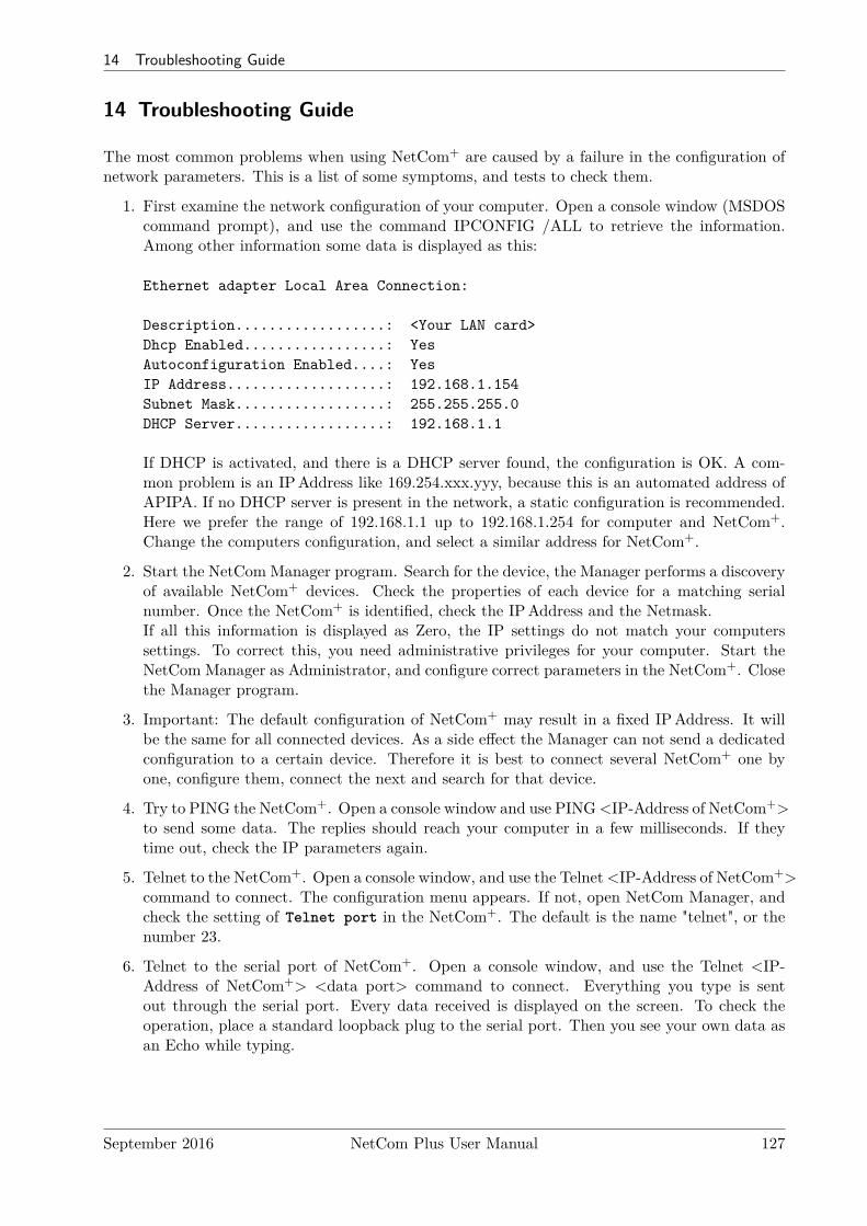
14 Troubleshooting Guide
14 Troubleshooting Guide
The most common problems when using NetCom+ are caused by a failure in the configuration ofnetwork parameters. This is a list of some symptoms, and tests to check them.
1. First examine the network configuration of your computer. Open a console window (MSDOScommand prompt), and use the command IPCONFIG /ALL to retrieve the information.Among other information some data is displayed as this:
Ethernet adapter Local Area Connection:
Description..................: <Your LAN card>Dhcp Enabled.................: YesAutoconfiguration Enabled....: YesIP Address...................: 192.168.1.154Subnet Mask..................: 255.255.255.0DHCP Server..................: 192.168.1.1
If DHCP is activated, and there is a DHCP server found, the configuration is OK. A com-mon problem is an IPAddress like 169.254.xxx.yyy, because this is an automated address ofAPIPA. If no DHCP server is present in the network, a static configuration is recommended.Here we prefer the range of 192.168.1.1 up to 192.168.1.254 for computer and NetCom+.Change the computers configuration, and select a similar address for NetCom+.
2. Start the NetCom Manager program. Search for the device, the Manager performs a discoveryof available NetCom+ devices. Check the properties of each device for a matching serialnumber. Once the NetCom+ is identified, check the IPAddress and the Netmask.If all this information is displayed as Zero, the IP settings do not match your computerssettings. To correct this, you need administrative privileges for your computer. Start theNetCom Manager as Administrator, and configure correct parameters in the NetCom+. Closethe Manager program.
3. Important: The default configuration of NetCom+ may result in a fixed IPAddress. It willbe the same for all connected devices. As a side effect the Manager can not send a dedicatedconfiguration to a certain device. Therefore it is best to connect several NetCom+ one byone, configure them, connect the next and search for that device.
4. Try to PING the NetCom+. Open a console window and use PING <IP-Address of NetCom+>to send some data. The replies should reach your computer in a few milliseconds. If theytime out, check the IP parameters again.
5. Telnet to the NetCom+. Open a console window, and use the Telnet <IP-Address of NetCom+>command to connect. The configuration menu appears. If not, open NetCom Manager, andcheck the setting of Telnet port in the NetCom+. The default is the name "telnet", or thenumber 23.
6. Telnet to the serial port of NetCom+. Open a console window, and use the Telnet <IP-Address of NetCom+> <data port> command to connect. Everything you type is sentout through the serial port. Every data received is displayed on the screen. To check theoperation, place a standard loopback plug to the serial port. Then you see your own data asan Echo while typing.
September 2016 NetCom Plus User Manual 127
14 Troubleshooting Guide
7. Check the Device Manager for error messages.
8. Run HyperTerminal, and open the serial port of NetCom+ device. Use the loopback plugto see the Echo of your typing. Use a Null Modem cable, and connect it from COM1 to theNetCom+. Open a second Window of HyperTerminal for COM1. Send some data betweenthese two windows. Transfer a file using ZMODEM protocol.
9. Often so-called Personal Firewall programs cause unspecific errors when other software startscommunicating. Check the documentation of the program to see how to allow access.
10. If some special function is not operative, check for the proper version of the Firmware. Incase of doubt install the latest version available (http://www.vscom.de/).
11. In rare cases or on special hardware the driver for Windows may have a problem. Pleaseload and install the latest version (http://www.vscom.de/) and try again. It is necessary touninstall the previous version.
12. Transmissions on IP-networks impose some extra delay in transmit and receive times. Thesecan add to between 5 and 10 milliseconds, depending on configurations. Such delays maycause applications to complain about non-functional hardware, in fact it is a protocol/delayproblem.
13. Wireless Connections may fail if the Access Point does not broadcast the SSID. The NetCom+
Servers need the broadcast to get the parameters from the Access Point. Hiding the SSID isnot a security feature anyway.
14. Many other problems occur because of a failed serial connection, caused by wrong cabling.Here are some frequent causes.
a) The serial cable in RS 232 mode may simply be to long. This mostly happens withhigher transmission rates.
b) In RS 422 and RS 485 it is mandatory to also connect the GND signal of all devices. It isa very frequent error not to do this. The information is transferred (and defined) by thepositive or negative difference of the Data+ and Data- lines. However the specificationrequires a common voltage range between the connected devices. To ensure this rangethe connection of GND is required.
c) A network in RS 485 requires biasing resistors (polarization). The Data+ line requiresa pull-up resistor to +5V, and the Data- line needs a pull-down resistor to GND. Thevalue is about 750Ω to 1 kΩ. When no station is transmitting, the Data-lines float. Thiswill cause noise and strange errors. The biasing resistors place a differential voltageto the lines, at least 200mV. These resistors must not exist on the network more thanonce. Therefore they are not enabled in the NetCom+ serial ports. To enable them it isnecessary to open the case, and set the Jumpers (see section 3.3).
September 2016 NetCom Plus User Manual 128
15 Glossary of Terms
15 Glossary of Terms
AES: Advanced Encryption StandardThe successor of the now insecure DES. AES provides strong and modern encryption, withlong keys up to 256 Bit (DES used 56 Bit).
APIPA: Automatic Private IPAddressingA scheme to self-assign an Address to a network device. The device selects an address of theLINKLOCAL range 169.254.1.0 to 169.254.254.255 by random. If this address is unused, itassigns it to itself. Otherwise the next address is tested. It became widespread with Windows98. The netmask is 255.255.0.0, these addresses are not routed on the Internet.
ART: Automatic Receive Transmit controlSpecial control for RS 485 modes. In RS 485 the line driver for transmitting must be disabled(tri-stated) when the device does not send data. In a 2-wire configuration this is known asdata direction change, with 4-wire it is called line contention.
CSV: Comma Separated ValuesA format to store tabular data in compact text form. Each line describes a new data set.Data fields are separated by a special character. Though the name CSV suggests a comma(’,’), in reality the delimiting character often is a semicolon or a <TAB> control character.
DHCP: Dynamic Host Configuration ProtocolA service used to retrieve an IP-configuration and optionally much more information from adatabase server.
FTP: File Transfer ProtocolA common protocol to access a file server.
HTTP: HyperText Transfer ProtocolThe protocol used by web browsers to access a web server.
Internet: The net connecting networksA set of protocols to exchange data between different networks. These information’s arecarried via a global network of fibers and satellite links.
IP: Internet ProtocolThe basic definitions for data packages. These Internet frames are stored and transportedembedded in data frames of the local network.
IPAddress: Internet AddressThe Internet address is noted as a group of 4 decimal numbers (IPv4). Each station on theInternet has a unique address. Some ranges are reserved for private networks, not connectedto the Internet.
LINKLOCAL: Address range for private networksThis range 169.254.0.0-169.254.255.255 (Netmask of 255.255.0.0) is reserved for private net-works, i.e. not connected to the Internet. Designed for small number of stations, using someautomatic configuration scheme. Used with APIPA.
NAT: Network Address TranslationA technique to have a private LAN share one (few) public IPAddress(es). With NAT thetransport information in IP-frames is replaced by the public data of the NAT-Router.
September 2016 NetCom Plus User Manual 129

15 Glossary of Terms
Netmask: Groups stations to a NetThe AND-operation between the IPAddress and the Mask is an important value. When tostations have the same result and the same mask, they are "in the same net". Which meansthey can communicate direct, without transmitting to a Router.
PAT: Port Address TranslationA technique to share a public IPAddress by many internal servers on private addresses. Thetarget address and port is replaced with values stored in an internal table. Mostly usedtogether with NAT.
Router: Transmits data over the InternetThe backbone devices of the Internet. Routers connect two networks together. On one sidethey receive data frames containing IP-data. They extract these data, and send them onanother side; there also stored in data frames of the second network. Typically they connectmore than two networks. The basic task is to decide which route the IP-data must take now.
RS232/V.24: common serial transmissionCharacters are sent as separate bits, timing is well defined. The medium is copper cable,using typical +/- 12 Volt. Each signal is defined related to a common ground; one wire persignal plus GND. RS232 is a point-to-point connection.
RS422/V.11: Industrial serial transmission (multidrop)A transmission method with balanced signals. Designed for higher speed, longer cables and isresistive against electrical noise. RS422 allows for up to 16 receivers. The typical transmissionis via twisted pair copper cable using balanced signals. Sender and receivers must share acommon voltage range (max. +/-7Volt difference). Two lines per signal, plus common GND.RS422 is a point-to-multipoint connection.
RS485: Industrial serial transmission (multipoint)The signals and cables are the same as RS422. The transmitters can go tri-state. Severalstations can send data on the same lines, at different times. RS485 is a multipoint-to-multipoint connection.
SNMP: Simple Network Management ProtocolA general purpose configuration system. Devices understanding SNMP may be configuredand monitored.
TCP/IP: Transmission Control Program/Internet ProtocolTCP establishes connections between two partners via the Internet. The data is sent in IP-frames, each frame is acknowledged be the recipient. Lost packages are repeated. Softwareusing TCP has a secured transmission; the delivery of the data is guaranteed.
TKIP: Temporal Key Integrity ProtocolAn encryption scheme for Wireless LAN. It was developed from the WEP. The key used forencryption is changed while data is transmitted. An attacker will not get enough data withthe same key to break the code.
UDP: User datagram protocolSimilar to TCP the data is sent in IP-frames. But in opposite there is no connection oracknowledge by the recipient. The transmission is faster for small data, but data can get lost.Software using UDP must handle the related problems.
September 2016 NetCom Plus User Manual 130
16 History
UPnP: Universal Plug and PlayDevices announce their presence on the network, and return their capabilities on the network.Depending on the type of device certain configuration is done, specific functions become avail-able.Specialized software can detect those devices, and offer their services without manual config-uration.
VPN: Virtual Private NetworkA public network is used to transport data for a limited set of stations. Drivers on thesestations generate virtual network cables between the stations. In many installations thecommunication through the public network is encrypted, to avoid tampering of the lines.
WEP: Wired Equivalent PrivacyAn encryption scheme used with early implementations of WLAN. The idea was to make itas difficult to read other persons data, as it was with cable communications. Due to weakdefinitions in WEP nowadays it may cost an attacker less than a minute to get the currentencryption key.
WLAN: short for Wireless LANThis is a general name, however today this phrase is used for the IEEE 802.11-protocoldefinitions.
WPA: Wireless Protected AccessThis is the successor of WEP. WPA not only includes better/stronger encryption, there isalso a set of functions to restrict access by means of user authorization, or different hardwareparameters (MAC address, distance).
WPA2: Wireless Protected Access 2This a modified version of WPA. Most important is the implementation of AES-256 as avail-able cypher.
16 History
January 2015 First release of manual for NetCom Plus
February 2015 Add WLAN configurationAdd Modbus/TCP on NetCom Plus 811 DIO
May 2015 Complete the list of models
September_2015 More pictures, and technical data refinedFirmware Version 3.2.2Support for Port Expansion via USB-COM Plus modelsInstructions (FAQ) for Linux use
January 2016 Remote Access by viaVPN documented (Chapter 11)PPP Option removedOrange LED for 3G/4G mobile network addedFirmware Version 3.3.1
August 2016 New Driver for NetCom+
Firmware Version 3.3.4
September 2016 NetCom Plus User Manual 131

16 History
September 2016 Operation Modes correctedFirmware Version 3.3.5
September 2016 NetCom Plus User Manual 132