Embed Size (px)
Citation preview
SVA026 Netcom 2 User Manual ver5 1
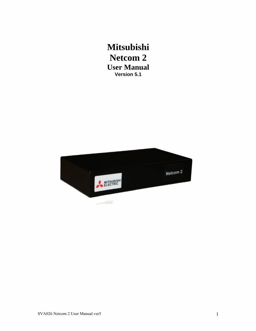
Mitsubishi Netcom 2
User Manual Version 5.1
SVA026 Netcom 2 User Manual ver5 2
TableofContents1. What is a Netcom? .......................................................................................................... 3 2. Who do I Contact For Technical Support? ..................................................................... 3 3. What are the System Requirements for Netcom? ........................................................... 3 3.1 Operating System Requirements................................................................................... 3 3.2 UPSMAN WINDOWS Solution: ................................................................................. 4 3.3 UPSMAN UNIX Solution: ........................................................................................... 4 3.4 APPLE MAC X Solution: ............................................................................................. 4 3.5 UNMS II Solution : ....................................................................................................... 4 3.6 RCCMD Solution (shut downs): ................................................................................... 4 3.7 No longer supported UPSMAN versions (please choose RCCMD instead) : .............. 6 3.8 Web Browser Requirements ......................................................................................... 6 3.9 Special Requirements for Web Browsers ..................................................................... 6 3.10 Special Requirements for Firewall Access ................................................................. 6 4. How do I Configure the Netcom? ................................................................................... 7 4.1 Installing the Netcom Utilities ...................................................................................... 7 4.2 Configuring the Netcom ............................................................................................... 7 4.2.1 HyperTerminal Setup example (serial cable) ............................................................ 7 4.2.2 Configuring the IP address with Window XP. ........................................................... 8 4.2.3 Configuring the IP address with Windows 7 ........................................................... 13 5. How do I Update the Netcom Firmware? ..................................................................... 17 6. Netcom Web Server ...................................................................................................... 19 7.1 Login Page .................................................................................................................. 20 7.2 UPS Status Page/ UPS/ Overview .............................................................................. 21 7.3 Identification/UPS Identification Page ....................................................................... 23 7.4 Variables/Variables Page ............................................................................................ 24 7.5 Event Log/View Events Page ..................................................................................... 25 7.6 Agent Setup/UPS/Configuration Page ........................................................................ 26 7.7 Nominal Values/UPS Nominal Values Page .............................................................. 27 7.8 Nominal Values/UPS Nominal Values Setup ............................................................. 28 7.9 Shutdown/UPS Shutdown Setup Page ........................................................................ 29 7.11Overview/Network Setup Page .................................................................................. 32 7.12 IP Config/Setup/IP Configuration Page .................................................................... 33 7.13 HTTP/HTTP Setup Page .......................................................................................... 34 7.14 LDAP Servers/Setup/LDAP Servers Page ................................................................ 35 7.15 SNMP NMS/Setup SNMP Page ............................................................................... 36 7.16 SNMP Rec’rs/SNMP Receivers Page ....................................................................... 37 7.17 Event Notification/Event Notification ...................................................................... 38 7.19 Users/Setup/Users ..................................................................................................... 43 7.20 Email Alerts/ Setup/ Email Alerts............................................................................. 44 7.21 Time Setting/ Setup/ Time Settings .......................................................................... 45 7.22 Syslog Servers/ Setup/ Syslog Servers ..................................................................... 46 7.23 Events/ View/ Events ................................................................................................ 47
SVA026 Netcom 2 User Manual ver5 3
7.24 Preferences/ Preferences Page .................................................................................. 48 7.25 Restart/Restart Page .................................................................................................. 49 APPENDIX A RJ45 to DB9 pin out ................................................................................. 50 APPENDIX B 9700 and 2033A connection ..................................................................... 51 APPENDIX C SEC connections ....................................................................................... 52 APPENDIX D MIBS ........................................................................................................ 53
1.WhatisaNetcom? A Netcom is a standalone UPS peripheral used for UPS monitoring, event
management, SNMP interfacing, and critical event notification. It consists of a small computer with a serial interface for connecting to and communicating with a UPS, and an Ethernet interface for connecting to your local network. The Netcom has its own embedded web server to allow you to monitor the status of the UPS using a Web browser. Event management is also configured and performed on the Web Server. It supports the Simple Network Management Protocol (SNMP) for integration with a Network Management System and Telnet for configuration.
You can configure the Netcom to perform appropriate actions when an event is detected including email and remote computer shutdown. The optional Remote shutdown agent runs on one or more remote computers and communicates with the Netcom to allow remote shutdown of up to 500 computers powered by the UPS.
2.WhodoIContactForTechnicalSupport?
Contact the Technical Support group for help configuring and using Netcom or any Mitsubishi UPS product
Phone 724-778-5111 Fax 724-778-3146
3.WhataretheSystemRequirementsforNetcom?
The Netcom runs as a standalone unit. It includes a 120-volt AC power source plug, and a DE9 to RJ45 communications cable for connecting to the UPS. A standard network cable for connecting to the local Ethernet network must be provided. The 9900, 2033G and 9800AE UPS have an optional internal power supply that can be purchased, please contact your local Sales Representative for more details. 3.1 Operating System Requirements Installation procedure for the shut down codes are located on the CD provided with the Netcom in a file named “Shut Down Manual”. The user will need a copy of their sales order for the serial number of each shut down code.
SVA026 Netcom 2 User Manual ver5 4
The remote shutdown agents will run on the following operating systems:
3.2UPSMANWINDOWSSolution:WINDOWS 7 (Professional or higher) x86/x64 CPU WINDOWS Server 2008 CORE x64 CPU WINDOWS Server 2008 R 2 (Standard, Enterprise, Datacenter, Webserver) x64 CPU WINDOWS Server 2008 (Standard, Enterprise, Datacenter, Webserver) x64 CPU (Standard, Enterprise, Datacenter, Webserver) WINDOWS VISTA (Business or higher) x86/x64 CPU WINDOWS 2003 Server X86/X64 CPU WINDOWS XP (Professional or higher) x86/x64 CPU WINDOWS 2000 Server WINDOWS 2000 SP4 x86 CPU
3.3UPSMANUNIXSolution:SUN SOLARIS 8, 9, 10, 11 X86, X64 X32 & X64 & SPARC CPU IBM AIX V. 5.3 RS 6000 RISC and PowerPC CPU HP UNIX V 10.20, 11.0-11i HP PA-RISC CPU (not Itanium - only RCCMD !) LINUX X86 - all X86/x64 CPU based LINUX versions, eg. United 1.x /SCO Linux Server 4, LINUX SUSE 7-10.x & SLES, Fedora Linux, GENTOO Linux, RedHat 7.0- 9.0, RH 4, RH5.4x x32/x64, TurboLinux 6.1-6.5, 7.x, Debian 4-5.x, Caldera Open Linux 2.3, Open Linux 3.1.x, Ubuntu, CentOS X86/x64 and all other x86/x64 kernel 2 based LINUX, NOVELL OES-Linux
3.4APPLEMACXSolution: MAC OS X 10.4x, 10.5x Leopard, 10.6 Snow Leopard
3.5UNMSIISolution: WINDOWS XP from Service Pack 2, WINDOWS Server 2003 SP2
Multiple network shutdowns An RCCMD installation keycode opens access to RCCMD clients for all OS mentioned above.
3.6RCCMDSolution(shutdowns):
SVA026 Netcom 2 User Manual ver5 5
Additional to the above listed OS, the following listed RCCMD versions are available
From Mitsubishi. Please contact Mitsubishi for the following; VMWARE Sphere ESX 4 i VMWARE ESX Server 3.5x / 4 (VMWare certified) CITRIX XEN Server 4.5 and 5.5 and higher (Citrix certified) MICROSOFT HYPER-V 2008 CENTOS INTEL x86, x64 & IA64 CPU LINUX PowerPC CPU LINUX ITANIUM X64 CPU LINUX SUSE 6.3x APX ALPHA CPU HP UNIX 9 PA-RISC CPU HP UNIX V 11.2x, 11.3x SPARC & ITANIUM 64 CPU QNX 4 and QNX 6 on X86 MAC OS X 10.1-10.3 APPLE MAC OS 9.x or higher NOVELL NetWare 3.10, 3.11, 3.20 ,4.10-4.20, 5.0, 5.1, 6.0, 6.1, 6.5 IBM OS/2 Version WARP 3.0, 4.0, LAN SERVER 3.0, 4.0, 5.0 X86 CPU IBM AIX V. 3.25, 4.1, 4.3, 5.1, 5.2, 5.3 RS 6000 RISC and PowerPC CPU IBM AIX V. 6 on PowerPC4, 970, Power5, Power 6 CPU IBM AIX L (Linux) V. 6 on Power 6 CPU SIEMENS SINIX 5.41 MX 300 Z X86 CPU SCO OpenServer 5.x u. 6.x 4 X86 CPU SILICON GRAPHICS IRIX V. 6.5x RISC MIPS CPU WINDOWS 2008 X86/X64 Virtualserver HYPERVISOR WINDOWS 2003 Server ITANIUM 64 CPU WINDOWS 2000 SP4 x86 CPU WINDOWS NT 4 SVP 6 WINDOWS NT 3.51 and NT 4 SVP3-6a X86 CPU WINDOWS NT 3.51 ALPHA CPU WINDOWS NT 3.15 MIPS CPU WINDOWS 98SE & ME X86 CPU DEC UNIX SVR 3 OSF/1 ALPHA CPU DATA GENERAL UNIX X 86 CPU DATA GENERAL UNIX MOTOROLA M88 CPU MOTOROLA UNIX M88 CPU SUN SOLARIS 7 (5.7) SPARC CPU SUN OS 4 SPARC CPU UNIXWARE 2, 7 on X86 CPU, UNIXWARE 7.x SVR 4 compatible X86 CPU INTERACTIVE UNIX 3.2 X86 CPU SIEMENS SINIX 5.41 – 5.45, RELIANT UNIX 5.45x RM RISC HP/COMPAQ TRU64 V 5.x ALPHA CPU, Digital UNIX V 4.0-5.1 ALPHA CPU FREE BSD UNIX SVR 4 X86 V 4.4x and 6.x
SVA026 Netcom 2 User Manual ver5 6
3.7NolongersupportedUPSMANversions(pleasechooseRCCMDinstead):
DEC ULTRIX, HP UNIX 9 PA-RISC CPU, IBM OS/2 Version WARP 4.0 X86 CPU, IBM OS/2 Version LAN SERVER 3.0, 4.0, 5.0 INTEL CPU, IBM OS/2 SNMP sub-agent, IBM AIX V 3.25, IBM AIX 4.1, WINDOWS NT 3.51 INTEL CPU, WINDOWS NT 3.51 ALPHA CPU, NOVELL NetWare 3.11 and 3.12 INTEL CPU, INTERACTIVE UNIX 3.2, VMS 5.5 for VAX or ALPHA, SUN SOLARIS 2.5, LINUX SUSE 5.x and 6.x. WINDOWS NT 4.0 ALPHA CPU, DEC OPEN VMS on VAX CPU, V.5x, V.6x, V. 7x - UPSMAN V3, DEC OPEN VMS on ALPHA AXP CPU V.6x; APPLE MAC OS 9.4, DEC OPEN VMS on ALPHA CPU V 7.x, SIEMENS SINIX 5.41 – 5.45, RELIANT UNIX 5.45x RM RISC HP/COMPAQ TRUE 64 V 5.x ALPHA CPU, Digital UNIX V 4.0-5.1 ALPHA CPU,
3.8 Web Browser Requirements
Supported web browsers include: Internet Explorer 6.0 or higher The Netcom requires Macromedia Flash 6.0 or higher.
3.9 Special Requirements for Web Browsers
In some instances, the caching on a Web Browser can cause the current page not to be updated while navigating on the Netcom user interface. For example, while viewing the Event Log Page you might click on the Variables menu option but still see the Event Log page. If this happens, follow the steps to correctly configure the caching for your Web Browser to reload each page upon each visit. Below is the example procedure for Internet Explorer v6:
Open Internet Explorer and select the Tools menu option. Select the Internet Options submenu. Under the Temporary Internet files section, click the Settings button. Click the Every visit to the page radio button. Click the OK button. Close the Internet Options dialog box.
3.10 Special Requirements for Firewall Access
Firewalls installed on the network must allow for the Netcom communication.
Ensure that the web server port and all SNMP ports are allowed. When Windows XP
SVA026 Netcom 2 User Manual ver5 7
Service Pack 2 is installed on a computer it will turn on the personal firewall. Below are the steps to open up the web port for Netcom in Windows XP Firewall:
Select Start Menu > Control Panel. Select Network Connections and right click on the connection that is
being used. Click on Properties and click the Advanced tab in the Properties
dialogue. Press the Settings... button to bring up the Firewall dialogue. Go to the Exceptions tab and click the Add Port button.
For Name enter Netcom Web Port and for Port Number enter 80. Press the OK button. You now will be able to access the Netcom web port through the Windows XP
Firewall.
4.HowdoIConfiguretheNetcom?
4.1InstallingtheNetcomUtilities The Netcom CD contains the following:
SNMP MIB Netcom User Manual (PDF) Shut down installation procedure Netcom FAQ Firmware
To install the Netcom Utilities or access any of the documents, place the Netcom CD in the CD drive. The Netcom Utilities CD should automatically start. Follow the instructions provided on your screen. 4.2 Configuring the Netcom
The initial network settings can be made by connecting the Netcom to a serial communication program using the included configuration cable or cross over cable and laptop. 4.2.1 HyperTerminal Setup example (serial cable)
1. Connect the 9 pin connector to the PC and the 9 pin receptacle labeled “Serial RS232” on the Netcom.
SVA026 Netcom 2 User Manual ver5 8
2. Open a HyperTerminal session by selecting (Installed location may vary) Start > All Programs > Accessories > Communications > HyperTerminal. 3. Select an available communications port from the drop-down list. 4. Select the following port settings: Bits per second: 19200 Data bits: 8 Parity: None Stop bits: 1 Flow Control: None 5. Cycle power from the Netcom by pulling out the power connector and
reinserting. 6. Wait for > and type test, this must be done within five seconds. This will disable the time out function and allow the IP address to be changed. 7. Type setup and enter. 8. The default IP address, IP mask, and IP gateway will be displayed. 9. Enter your IP address and press enter. 10. Enter your sub net mask and press enter. 11. Enter your IP gateway and press enter. 12. After the IP gateway is entered it will ask to save the changes, enter y. 13. When connecting to a 9700 or 2033A the protocol must be change, this is accomplished by typing “ups m”. After entering ups m the user will see “Mitsubishi protocol selected”, the user must type in “commit” to save the change. 14. System will now reboot and is ready for Internet connectivity.
4.2.2ConfiguringtheIPaddresswithWindowXP.
1. Connect the cross over cable provided with the Netcom2 to your PC and the “Network” RJ45 port of the Netcom2.
2. Plug in the power supply included in the Netcom2 box to the +12VDC.
SVA026 Netcom 2 User Manual ver5 9
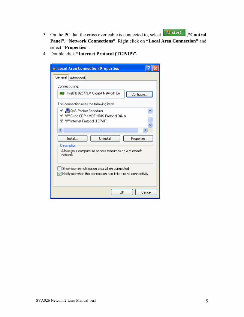
3. On the PC that the cross over cable is connected to, select ,“Control Panel”, “Network Connections”. Right click on “Local Area Connection” and select “Properties”.
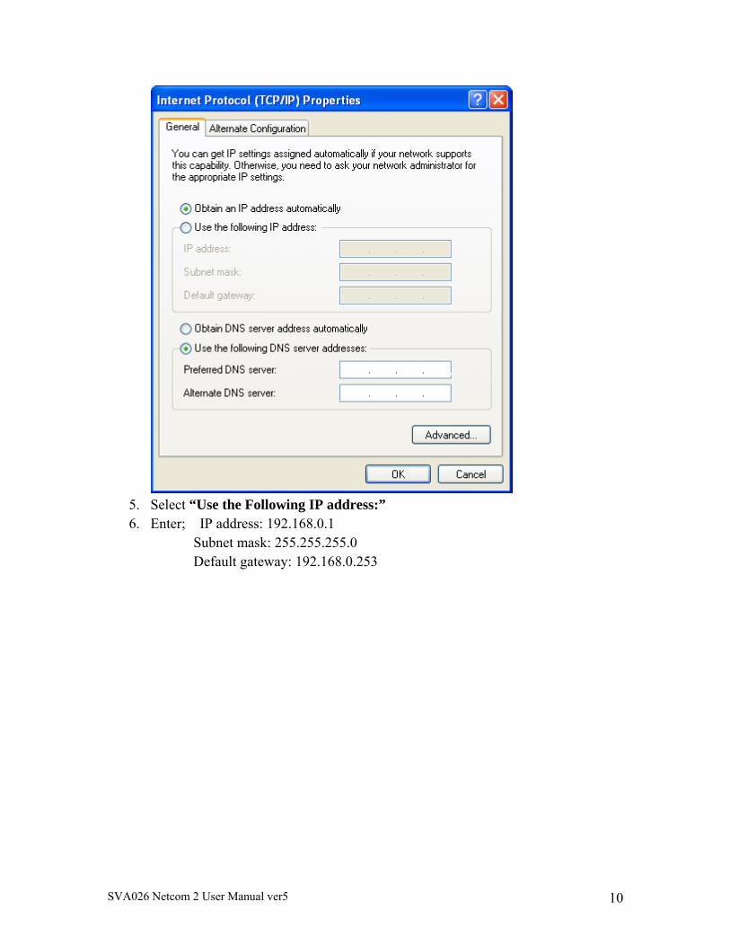
4. Double click “Internet Protocol (TCP/IP)”.
SVA026 Netcom 2 User Manual ver5 10
5. Select “Use the Following IP address:” 6. Enter; IP address: 192.168.0.1
Subnet mask: 255.255.255.0 Default gateway: 192.168.0.253
SVA026 Netcom 2 User Manual ver5 11
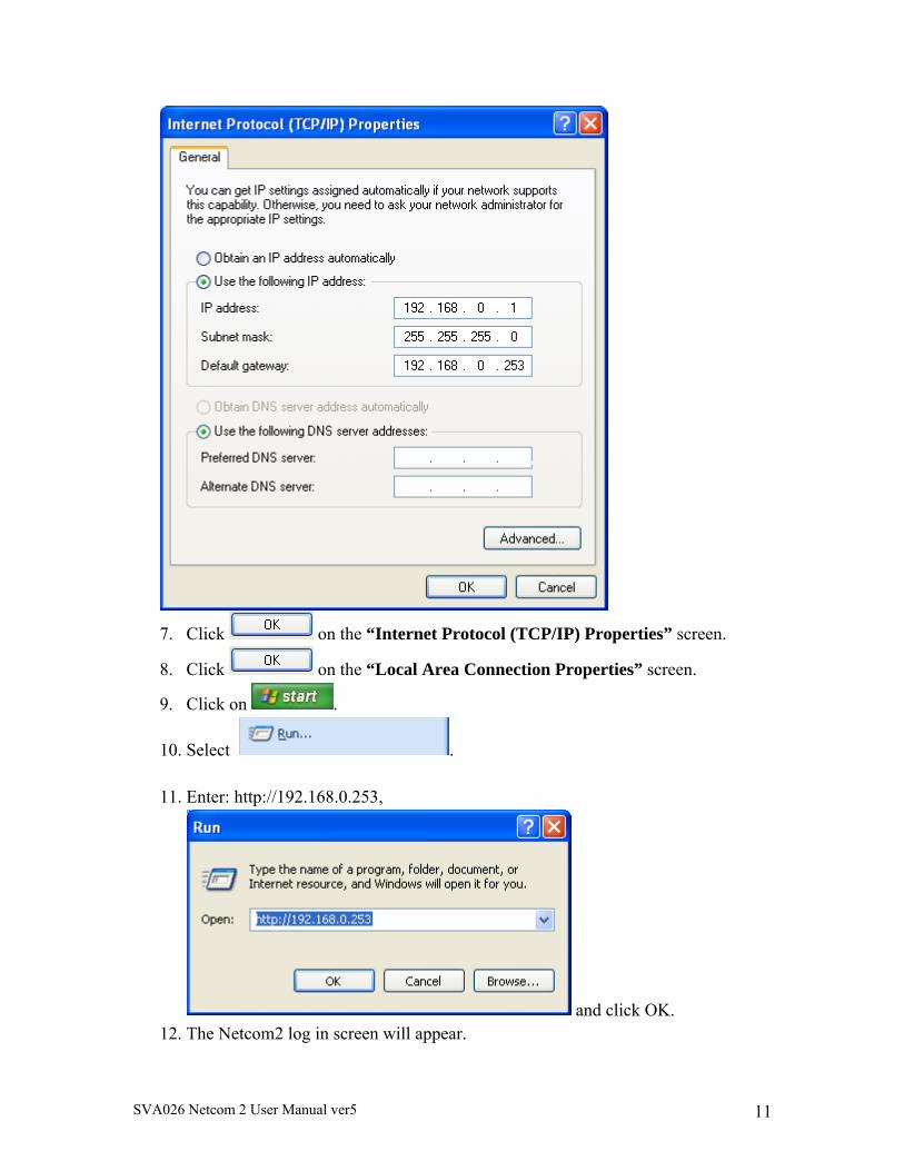
7. Click on the “Internet Protocol (TCP/IP) Properties” screen.
8. Click on the “Local Area Connection Properties” screen.
9. Click on .
10. Select .
11. Enter: http://192.168.0.253,
and click OK. 12. The Netcom2 log in screen will appear.
SVA026 Netcom 2 User Manual ver5 12
13. If the Netcom log in screen does not appear perform the following; a. Verify the cross over cable is connected to the Netcom2 port labeled
“Network” b. Verify the power light on the Netcom2 is green and the status light is blinking. c. Ping the entered IP address in the DOS prompt. d. Verify the “local area connection” is connected in the Network connections
screen 14. The default login and password of a Netcom is;
Username: admin Password: admin
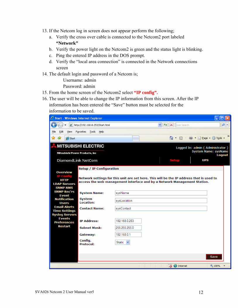
15. From the home screen of the Netcom2 select “IP config”. 16. The user will be able to change the IP information from this screen. After the IP
information has been entered the “Save” button must be selected for the information to be saved.
SVA026 Netcom 2 User Manual ver5 13
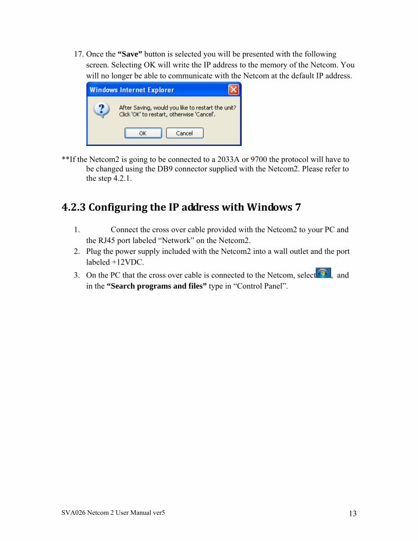
17. Once the “Save” button is selected you will be presented with the following screen. Selecting OK will write the IP address to the memory of the Netcom. You will no longer be able to communicate with the Netcom at the default IP address.
**If the Netcom2 is going to be connected to a 2033A or 9700 the protocol will have to be changed using the DB9 connector supplied with the Netcom2. Please refer to the step 4.2.1.
4.2.3ConfiguringtheIPaddresswithWindows7
1. Connect the cross over cable provided with the Netcom2 to your PC and the RJ45 port labeled “Network” on the Netcom2.
2. Plug the power supply included with the Netcom2 into a wall outlet and the port labeled +12VDC.
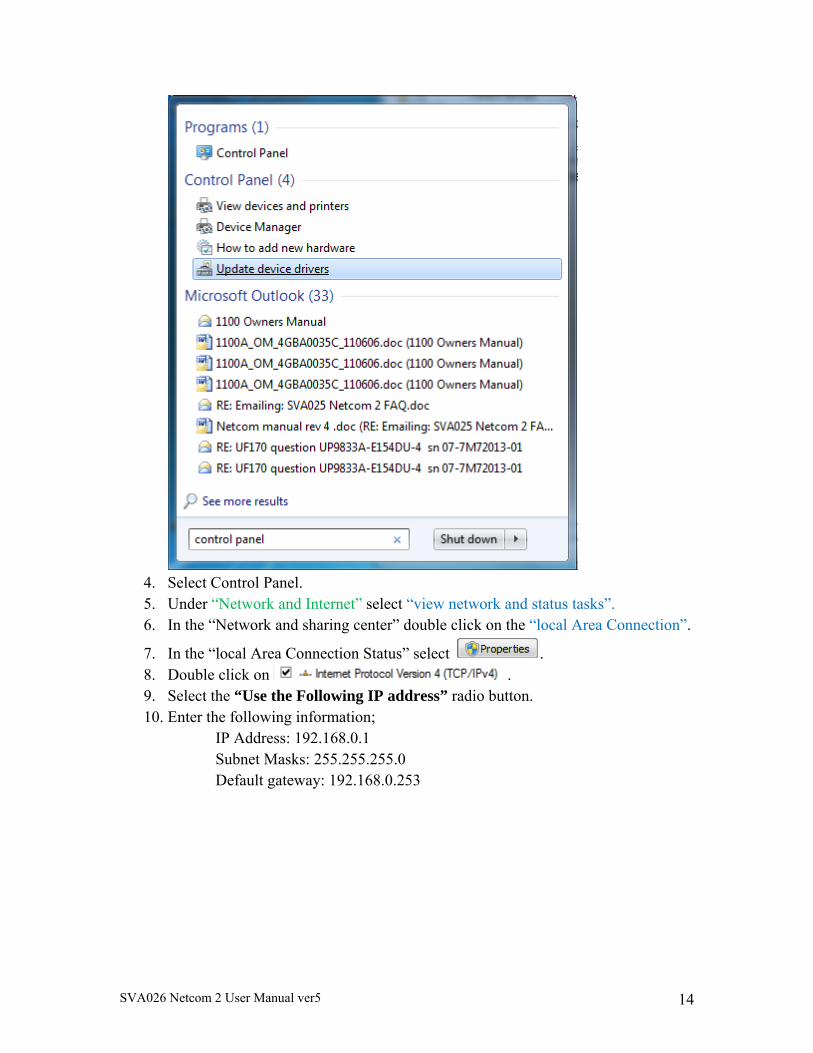
3. On the PC that the cross over cable is connected to the Netcom, select , and in the “Search programs and files” type in “Control Panel”.
SVA026 Netcom 2 User Manual ver5 14
4. Select Control Panel. 5. Under “Network and Internet” select “view network and status tasks”. 6. In the “Network and sharing center” double click on the “local Area Connection”.
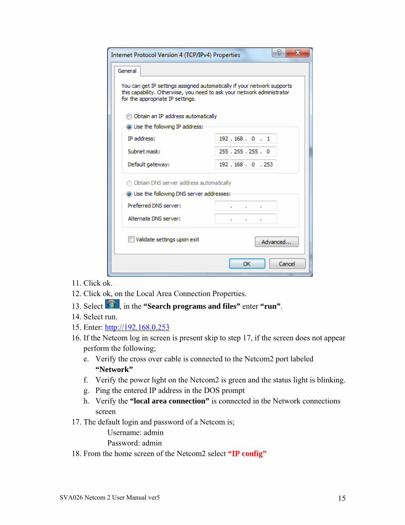
7. In the “local Area Connection Status” select . 8. Double click on . 9. Select the “Use the Following IP address” radio button. 10. Enter the following information;
IP Address: 192.168.0.1 Subnet Masks: 255.255.255.0 Default gateway: 192.168.0.253
SVA026 Netcom 2 User Manual ver5 15
11. Click ok. 12. Click ok, on the Local Area Connection Properties.
13. Select , in the “Search programs and files” enter “run”. 14. Select run. 15. Enter: http://192.168.0.253 16. If the Netcom log in screen is present skip to step 17, if the screen does not appear
perform the following; e. Verify the cross over cable is connected to the Netcom2 port labeled
“Network” f. Verify the power light on the Netcom2 is green and the status light is blinking. g. Ping the entered IP address in the DOS prompt h. Verify the “local area connection” is connected in the Network connections
screen 17. The default login and password of a Netcom is;
Username: admin Password: admin
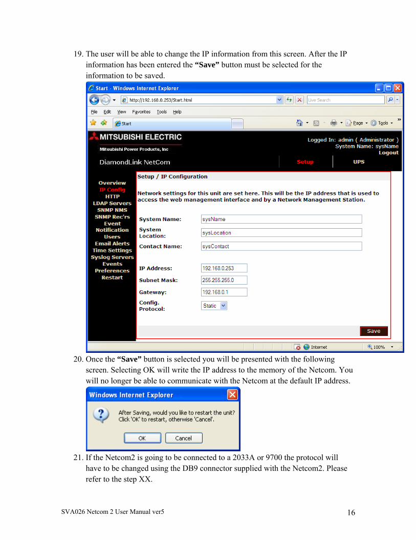
18. From the home screen of the Netcom2 select “IP config”
SVA026 Netcom 2 User Manual ver5 16
19. The user will be able to change the IP information from this screen. After the IP information has been entered the “Save” button must be selected for the information to be saved.
20. Once the “Save” button is selected you will be presented with the following
screen. Selecting OK will write the IP address to the memory of the Netcom. You will no longer be able to communicate with the Netcom at the default IP address.
21. If the Netcom2 is going to be connected to a 2033A or 9700 the protocol will
have to be changed using the DB9 connector supplied with the Netcom2. Please refer to the step XX.
SVA026 Netcom 2 User Manual ver5 17
5.HowdoIUpdatetheNetcomFirmware?
Configuration Upgrade.
The Netcom2 is shipped with firmware installed, if needed the latest firmware version is available for download at; www.meppi.com/Products/UninterruptiblePowerSupplies/Communication.
The firmware version installed in the Netcom2 can be found in the log in screen under the user name and password.
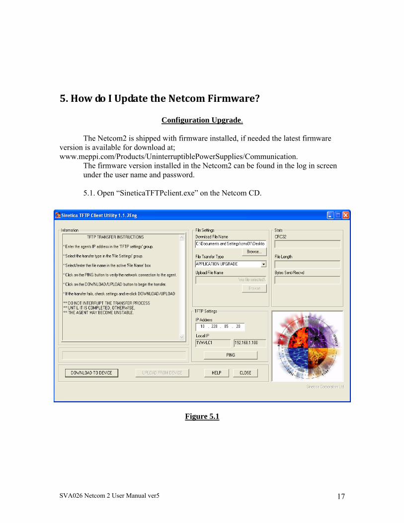
5.1. Open “SineticaTFTPclient.exe” on the Netcom CD.
Figure 5.1
SVA026 Netcom 2 User Manual ver5 18
5.2. In the 'File Settings' group select 'APPLICATION UPGRADE' from the 'File Transfer Type' drop down list. 5.3. In the 'Download File Name' edit box select the name of the file, XX.XX.X.bin, supplied on the Netcom 2 CD. 5.4. In the ‘TFTP Settings’ group enter the required IP address of the unit to be upgraded in the ‘IP Address’ box. 5.5. Click the 'DOWNLOAD TO DEVICE' button. A blue task bar will flow from left to right and data information will be displayed in the information box. When “connection closed” appears the firmware installation will be complete. 5.6. The new configuration data will be written to the EEPROM in the Netcom2
unit 5.7. If the Netcom is going to be communicating with a 2033A or 9700 the protocol will have to be selected. This is done in the HyperTerminal session in section
SVA026 Netcom 2 User Manual ver5 19
6.NetcomWebServer
Before attempting to connect to the Netcom2 for the first time check the following;
1. An IP address has been assigned 2. The supplied RJ45 to DB9 cable is connected to the port labeled UPS and
connected to the UPS communication port (contact Mitsubishi or your local service group)
3. The intranet cable is connected to the Network plug and the amber and green lights are flashing
4. Power is applied to the Netcom and the power and status lights are on. 5. The proper protocol has been selected; 9700 and 2033A UPS require MIT all
other require SEC.
SVA026 Netcom 2 User Manual ver5 20
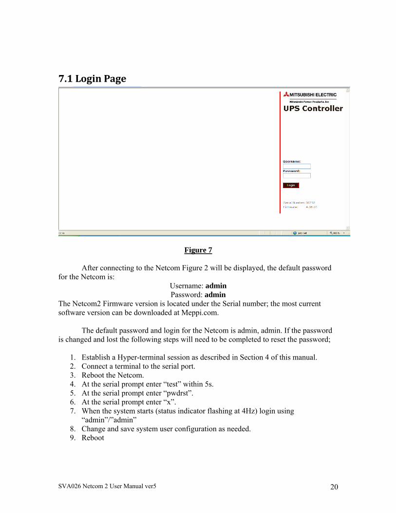
7.1LoginPage
Figure 7
After connecting to the Netcom Figure 2 will be displayed, the default password for the Netcom is:
Username: admin Password: admin
The Netcom2 Firmware version is located under the Serial number; the most current software version can be downloaded at Meppi.com.
The default password and login for the Netcom is admin, admin. If the password
is changed and lost the following steps will need to be completed to reset the password;
1. Establish a Hyper-terminal session as described in Section 4 of this manual. 2. Connect a terminal to the serial port. 3. Reboot the Netcom. 4. At the serial prompt enter “test” within 5s. 5. At the serial prompt enter “pwdrst”. 6. At the serial prompt enter “x”. 7. When the system starts (status indicator flashing at 4Hz) login using
“admin”/”admin” 8. Change and save system user configuration as needed. 9. Reboot
SVA026 Netcom 2 User Manual ver5 21
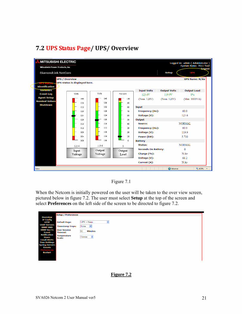
7.2UPSStatusPage/UPS/Overview
Figure 7.1
When the Netcom is initially powered on the user will be taken to the over view screen, pictured below in figure 7.2. The user must select Setup at the top of the screen and select Preferences on the left side of the screen to be directed to figure 7.2.
Figure 7.2
SVA026 Netcom 2 User Manual ver5 22
Under the default, select UPS ->Status this will set the status page to default. The user can also select the time before the Netcom2 times out by selecting the User Session Timeout: drop down. If the Input Volts, Output volts, or Output load is any color other than green the values are out of limits. This can be corrected by entering the correct values in the Nominal Values page or the values are out of the UPS’s operating range. If the Input Volts, Output volts, or Output load graphs are to the max this also is an indication of incorrect values entered in the Nominal Values page.
SVA026 Netcom 2 User Manual ver5 23
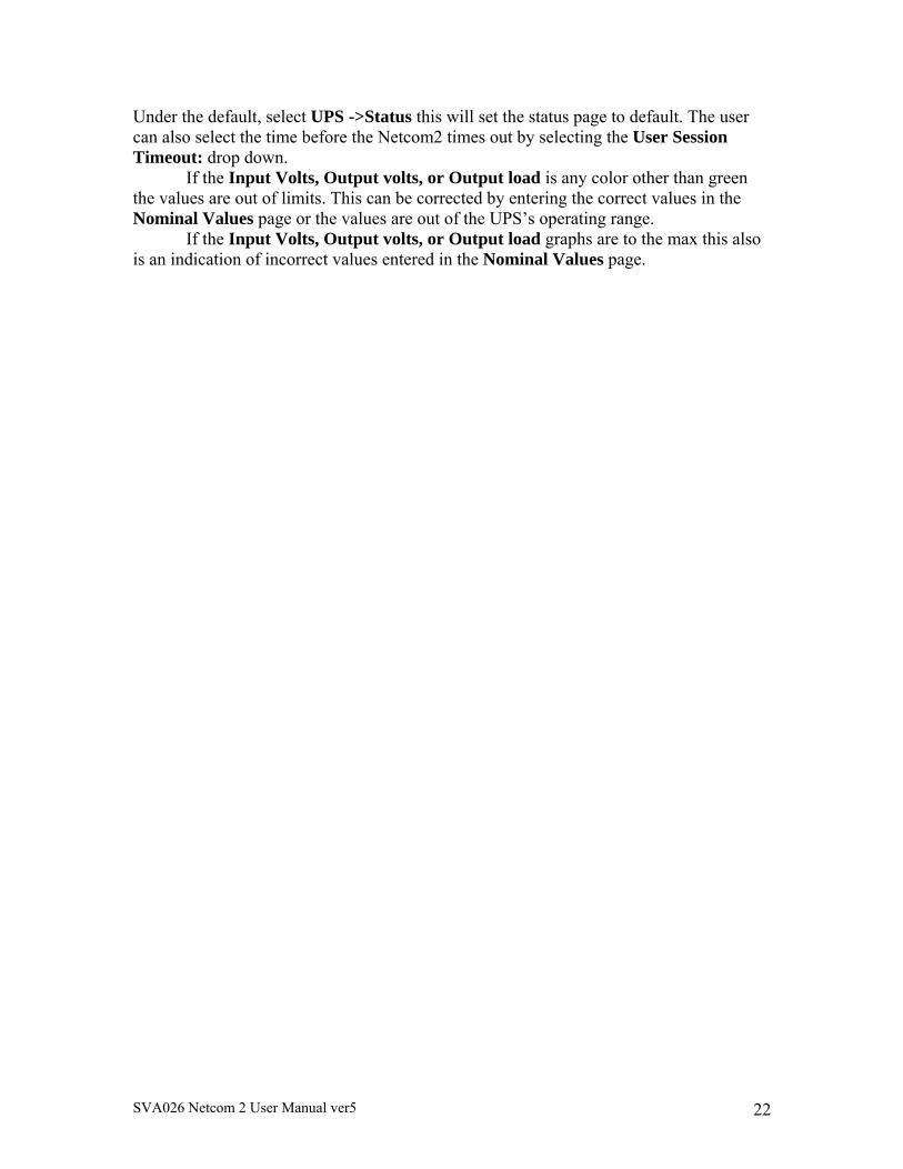
7.3Identification/UPSIdentificationPage
Figure 7.3 Click on the Identification menu option to display the UPS serial number,
contact name, contact email, contact phone number and battery information. This information is input at the Agent Setup menu (see figure 7.7).
SVA026 Netcom 2 User Manual ver5 24
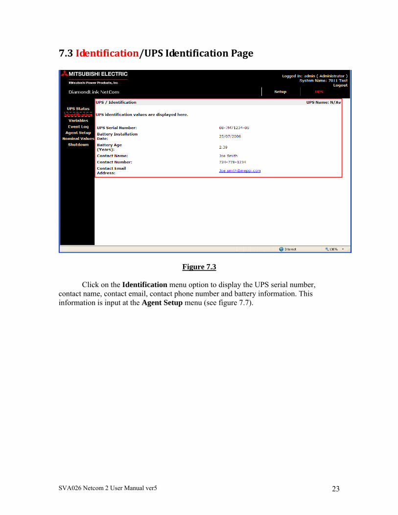
7.4Variables/VariablesPage
Figure 7.4
Click the Variables page to display the variables page. This page displays a list of the available UPS variables. The variables displayed may vary depending on the unit that is being monitored.
SVA026 Netcom 2 User Manual ver5 25
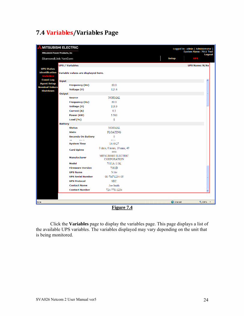
7.5EventLog/ViewEventsPage
Figure 7.5
Click on the Event Log menu option to display the View/Events page. The event log will hold the latest events received from the UPS. The events can be sorted by month, year and order of occurrence by selecting the View Event.
When an event occurs, it will be written to the event log with a date/time stamp. When the event is cleared (alarm removed), it will be written to the event log in the format “event removed”, where event is the name of the event being cleared. Click the Clear Log button to clear the event log.
SVA026 Netcom 2 User Manual ver5 26
7.6AgentSetup/UPS/ConfigurationPage
Figure 7.6
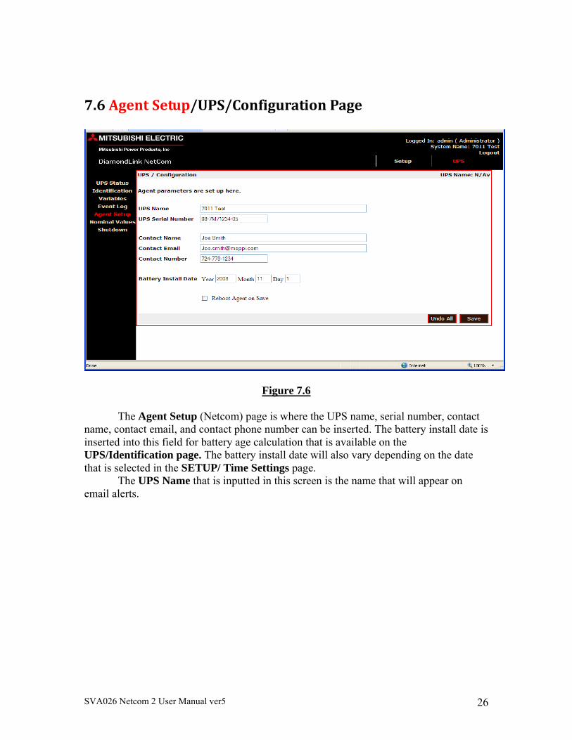
The Agent Setup (Netcom) page is where the UPS name, serial number, contact name, contact email, and contact phone number can be inserted. The battery install date is inserted into this field for battery age calculation that is available on the UPS/Identification page. The battery install date will also vary depending on the date that is selected in the SETUP/ Time Settings page.
The UPS Name that is inputted in this screen is the name that will appear on email alerts.
SVA026 Netcom 2 User Manual ver5 27
7.7NominalValues/UPSNominalValuesPage
Figure 7.7
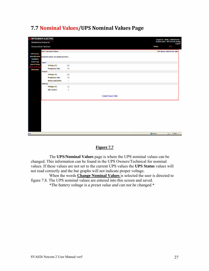
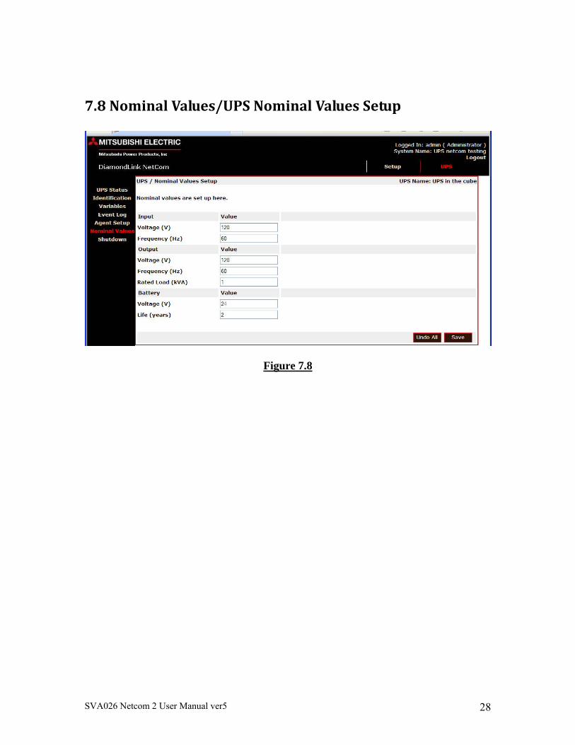
The UPS/Nominal Values page is where the UPS nominal values can be changed. This information can be found in the UPS Owners/Technical for nominal values. If these values are not set to the current UPS values the UPS Status values will not read correctly and the bar graphs will not indicate proper voltage.
When the words Change Nominal Values is selected the user is directed to figure 7.8. The UPS nominal values are entered into this screen and saved.
*The battery voltage is a preset value and can not be changed.*
SVA026 Netcom 2 User Manual ver5 28
7.8NominalValues/UPSNominalValuesSetup
Figure 7.8
SVA026 Netcom 2 User Manual ver5 29
7.9Shutdown/UPSShutdownSetupPage
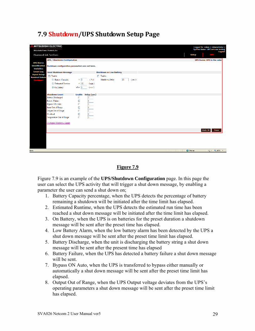
Figure 7.9 Figure 7.9 is an example of the UPS/Shutdown Configuration page. In this page the user can select the UPS activity that will trigger a shut down message, by enabling a parameter the user can send a shut down on;
1. Battery Capacity percentage, when the UPS detects the percentage of battery remaining a shutdown will be initiated after the time limit has elapsed.
2. Estimated Runtime, when the UPS detects the estimated run time has been reached a shut down message will be initiated after the time limit has elapsed.
3. On Battery, when the UPS is on batteries for the preset duration a shutdown message will be sent after the preset time has elapsed.
4. Low Battery Alarm, when the low battery alarm has been detected by the UPS a shut down message will be sent after the preset time limit has elapsed.
5. Battery Discharge, when the unit is discharging the battery string a shut down message will be sent after the present time has elapsed
6. Battery Failure, when the UPS has detected a battery failure a shut down message will be sent.
7. Bypass ON Auto, when the UPS is transferred to bypass either manually or automatically a shut down message will be sent after the preset time limit has elapsed.
8. Output Out of Range, when the UPS Output voltage deviates from the UPS’s operating parameters a shut down message will be sent after the preset time limit has elapsed.
SVA026 Netcom 2 User Manual ver5 30
9. Input Out of Range, when the UPS input voltage deviates from the UPS’s operating parameters a shut down message will be sent after the preset time limit has been reached.
10. Overload, when the unit is overload and the preset timer has expired a shut down message will be sent.
11. Temperature Out of Range, when the UPS experiences temperature that exceed the operating standards and the timer has elapsed a shut down message will be sent.
Each parameter has a time limit or percentage attached to it. If the parameter is reached but does not remain for the duration of the time or percentage limit a shutdown will NOT be initiated. The Configure Shutdown Agents when selected.
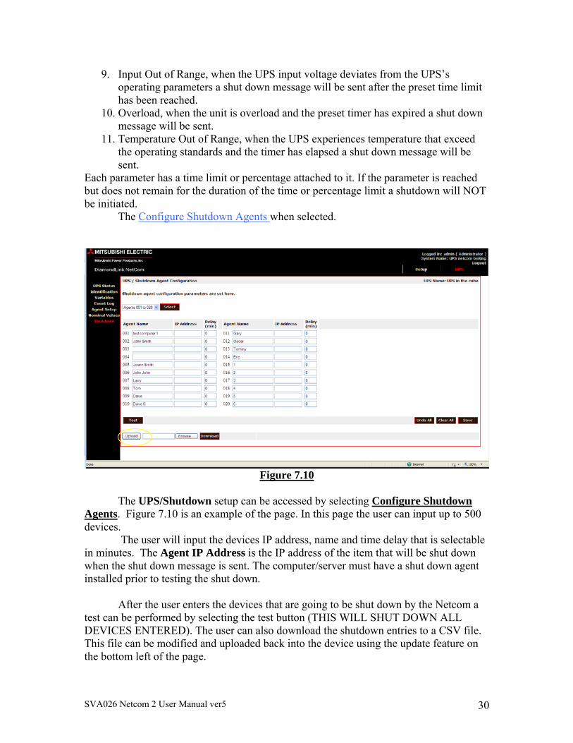
Figure 7.10
The UPS/Shutdown setup can be accessed by selecting Configure Shutdown
Agents. Figure 7.10 is an example of the page. In this page the user can input up to 500 devices.
The user will input the devices IP address, name and time delay that is selectable in minutes. The Agent IP Address is the IP address of the item that will be shut down when the shut down message is sent. The computer/server must have a shut down agent installed prior to testing the shut down.
After the user enters the devices that are going to be shut down by the Netcom a
test can be performed by selecting the test button (THIS WILL SHUT DOWN ALL DEVICES ENTERED). The user can also download the shutdown entries to a CSV file. This file can be modified and uploaded back into the device using the update feature on the bottom left of the page.
SVA026 Netcom 2 User Manual ver5 31
Note: Not all UPS support the estimated runtime variable. -On Battery – Click the On Battery radio button. When the UPS goes on
battery, a shutdown message will be sent to all listed systems.
SVA026 Netcom 2 User Manual ver5 32
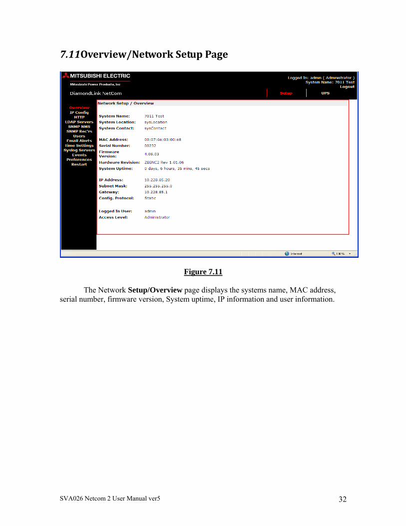
7.11Overview/NetworkSetupPage
Figure 7.11
The Network Setup/Overview page displays the systems name, MAC address, serial number, firmware version, System uptime, IP information and user information.
SVA026 Netcom 2 User Manual ver5 33
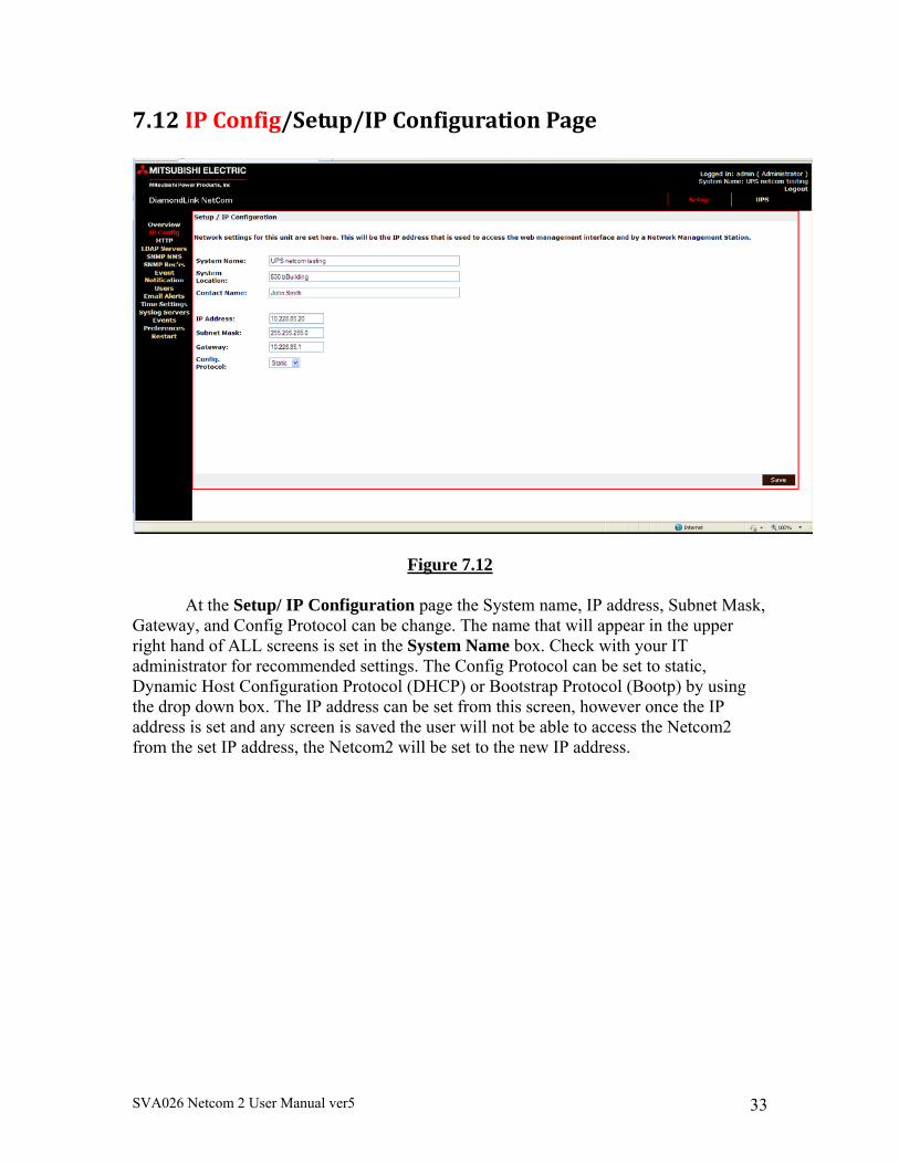
7.12IPConfig/Setup/IPConfigurationPage
Figure 7.12
At the Setup/ IP Configuration page the System name, IP address, Subnet Mask, Gateway, and Config Protocol can be change. The name that will appear in the upper right hand of ALL screens is set in the System Name box. Check with your IT administrator for recommended settings. The Config Protocol can be set to static, Dynamic Host Configuration Protocol (DHCP) or Bootstrap Protocol (Bootp) by using the drop down box. The IP address can be set from this screen, however once the IP address is set and any screen is saved the user will not be able to access the Netcom2 from the set IP address, the Netcom2 will be set to the new IP address.
SVA026 Netcom 2 User Manual ver5 34
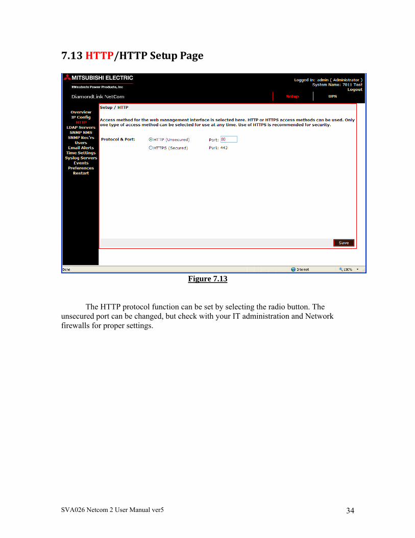
7.13HTTP/HTTPSetupPage
Figure 7.13
The HTTP protocol function can be set by selecting the radio button. The unsecured port can be changed, but check with your IT administration and Network firewalls for proper settings.
SVA026 Netcom 2 User Manual ver5 35
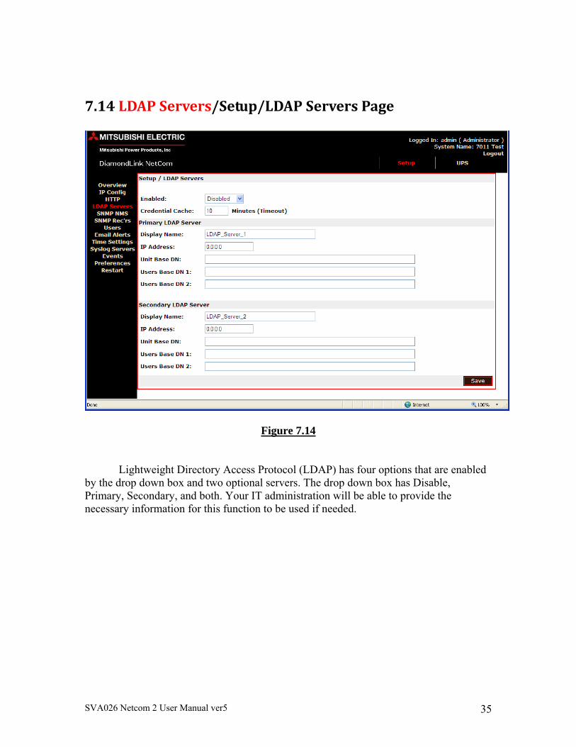
7.14LDAPServers/Setup/LDAPServersPage
Figure 7.14
Lightweight Directory Access Protocol (LDAP) has four options that are enabled by the drop down box and two optional servers. The drop down box has Disable, Primary, Secondary, and both. Your IT administration will be able to provide the necessary information for this function to be used if needed.
SVA026 Netcom 2 User Manual ver5 36
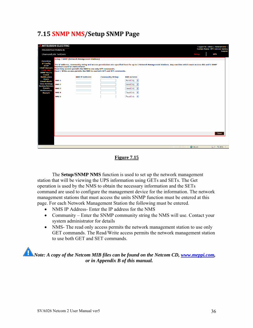
7.15SNMPNMS/SetupSNMPPage
Figure 7.15
The Setup/SNMP NMS function is used to set up the network management station that will be viewing the UPS information using GETs and SETs. The Get operation is used by the NMS to obtain the necessary information and the SETs command are used to configure the management device for the information. The network management stations that must access the units SNMP function must be entered at this page. For each Network Management Station the following must be entered.
NMS IP Address- Enter the IP address for the NMS Community – Enter the SNMP community string the NMS will use. Contact your
system administrator for details NMS- The read only access permits the network management station to use only
GET commands. The Read/Write access permits the network management station to use both GET and SET commands.
Note: A copy of the Netcom MIB files can be found on the Netcom CD, www.meppi.com, or in Appendix B of this manual.
SVA026 Netcom 2 User Manual ver5 37
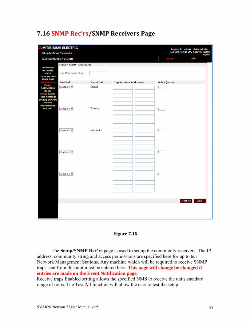
7.16SNMPRec’rs/SNMPReceiversPage
Figure 7.16
The Setup/SNMP Rec’rs page is used to set up the community receivers. The IP address, community string and access permissions are specified here for up to ten Network Management Stations. Any machine which will be required to receive SNMP traps sent from this unit must be entered here. This page will change be changed if entries are made on the Event Notification page. Receive traps Enabled setting allows the specified NMS to receive the units standard range of traps. The Test All function will allow the user to test the setup.
SVA026 Netcom 2 User Manual ver5 38
7.17EventNotification/EventNotification
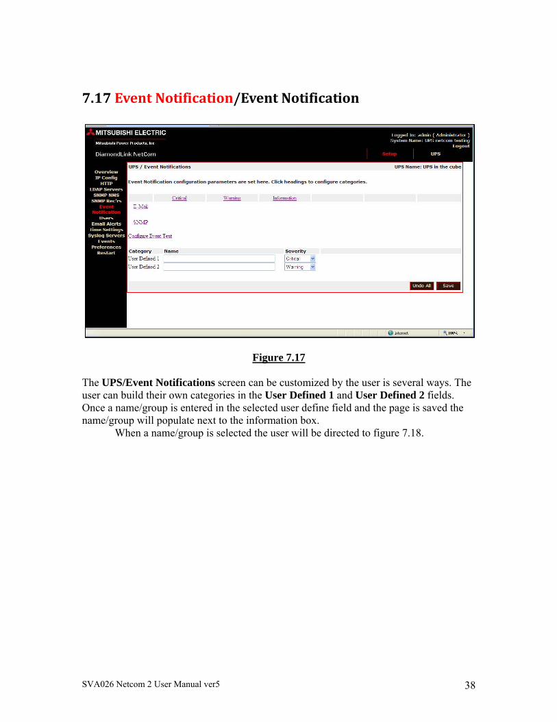
Figure 7.17
The UPS/Event Notifications screen can be customized by the user is several ways. The user can build their own categories in the User Defined 1 and User Defined 2 fields. Once a name/group is entered in the selected user define field and the page is saved the name/group will populate next to the information box. When a name/group is selected the user will be directed to figure 7.18.
SVA026 Netcom 2 User Manual ver5 39
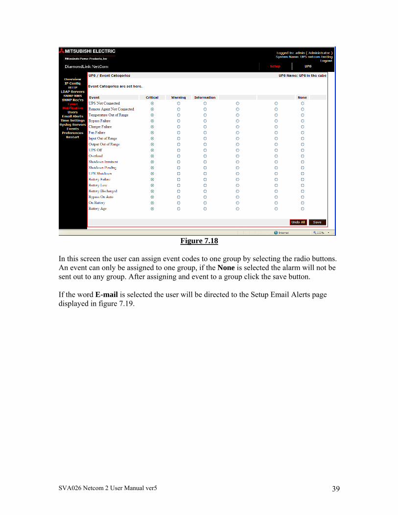
Figure 7.18
In this screen the user can assign event codes to one group by selecting the radio buttons. An event can only be assigned to one group, if the None is selected the alarm will not be sent out to any group. After assigning and event to a group click the save button. If the word E-mail is selected the user will be directed to the Setup Email Alerts page displayed in figure 7.19.
SVA026 Netcom 2 User Manual ver5 40
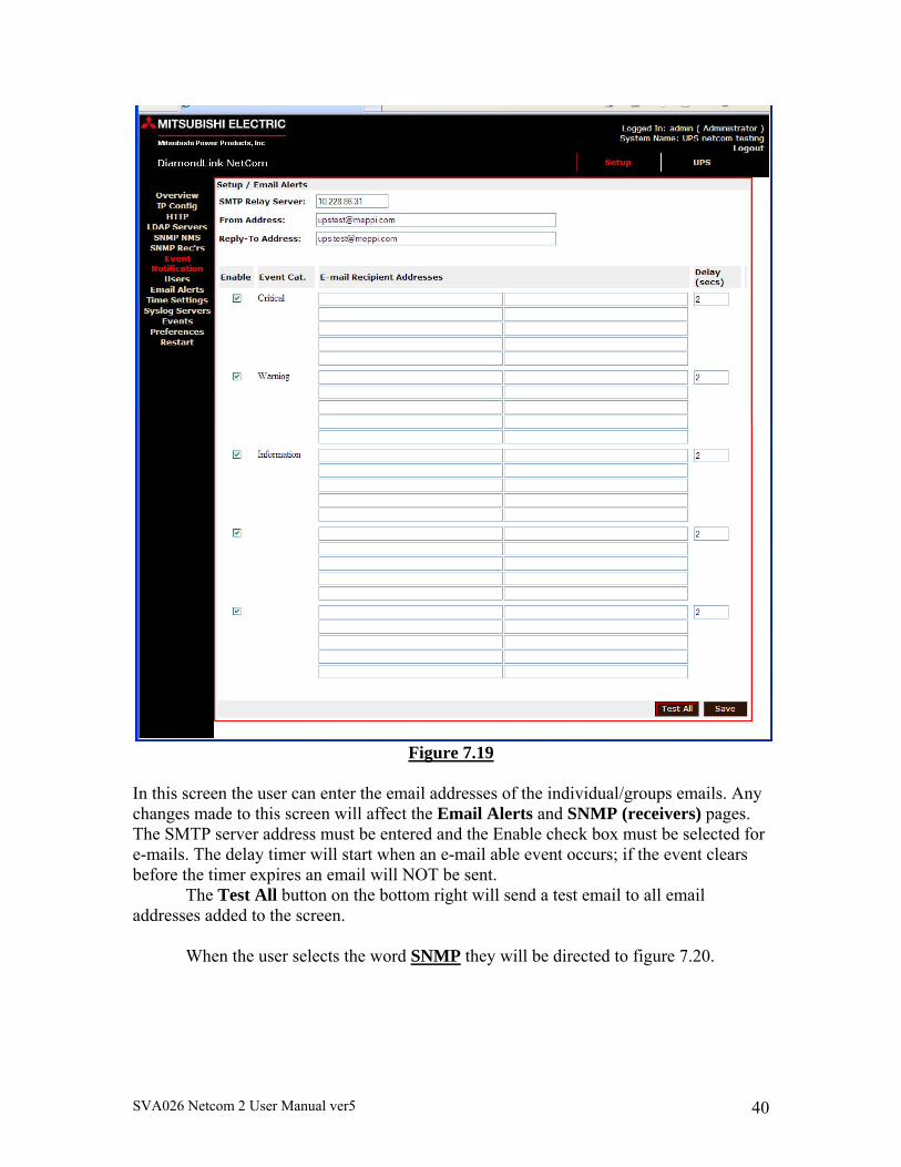
Figure 7.19
In this screen the user can enter the email addresses of the individual/groups emails. Any changes made to this screen will affect the Email Alerts and SNMP (receivers) pages. The SMTP server address must be entered and the Enable check box must be selected for e-mails. The delay timer will start when an e-mail able event occurs; if the event clears before the timer expires an email will NOT be sent. The Test All button on the bottom right will send a test email to all email addresses added to the screen. When the user selects the word SNMP they will be directed to figure 7.20.
SVA026 Netcom 2 User Manual ver5 41
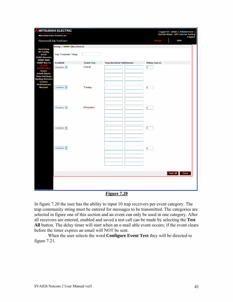
Figure 7.20
In figure 7.20 the user has the ability to input 10 trap receivers per event category. The trap community string must be entered for messages to be transmitted. The categories are selected in figure one of this section and an event can only be used in one category. After all receivers are entered, enabled and saved a test call can be made by selecting the Test All button. The delay timer will start when an e-mail able event occurs; if the event clears before the timer expires an email will NOT be sent. When the user selects the word Configure Event Text they will be directed to figure 7.21.
SVA026 Netcom 2 User Manual ver5 42
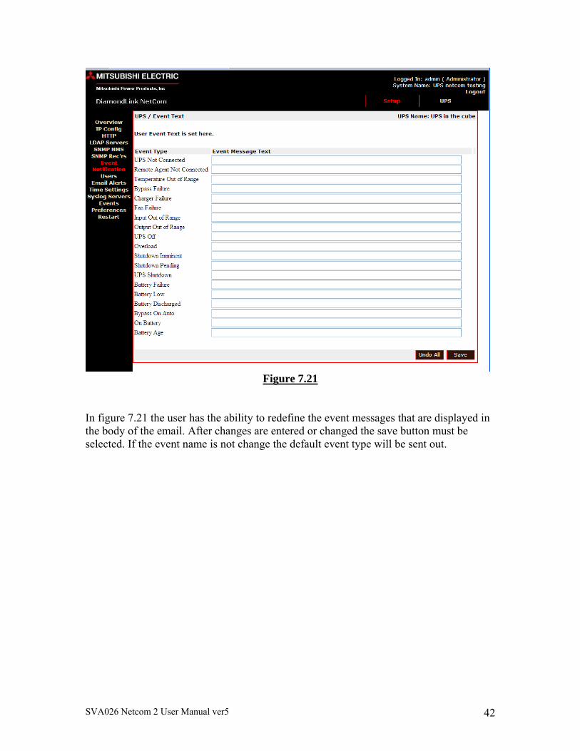
Figure 7.21
In figure 7.21 the user has the ability to redefine the event messages that are displayed in the body of the email. After changes are entered or changed the save button must be selected. If the event name is not change the default event type will be sent out.
SVA026 Netcom 2 User Manual ver5 43
7.19Users/Setup/Users
Figure 7.22
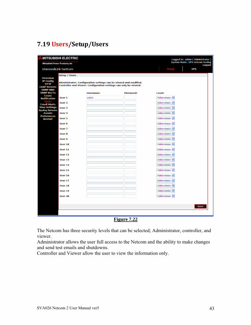
The Netcom has three security levels that can be selected; Administrator, controller, and viewer. Administrator allows the user full access to the Netcom and the ability to make changes and send test emails and shutdowns. Controller and Viewer allow the user to view the information only.
SVA026 Netcom 2 User Manual ver5 44
7.20EmailAlerts/Setup/EmailAlerts
Figure 7.23
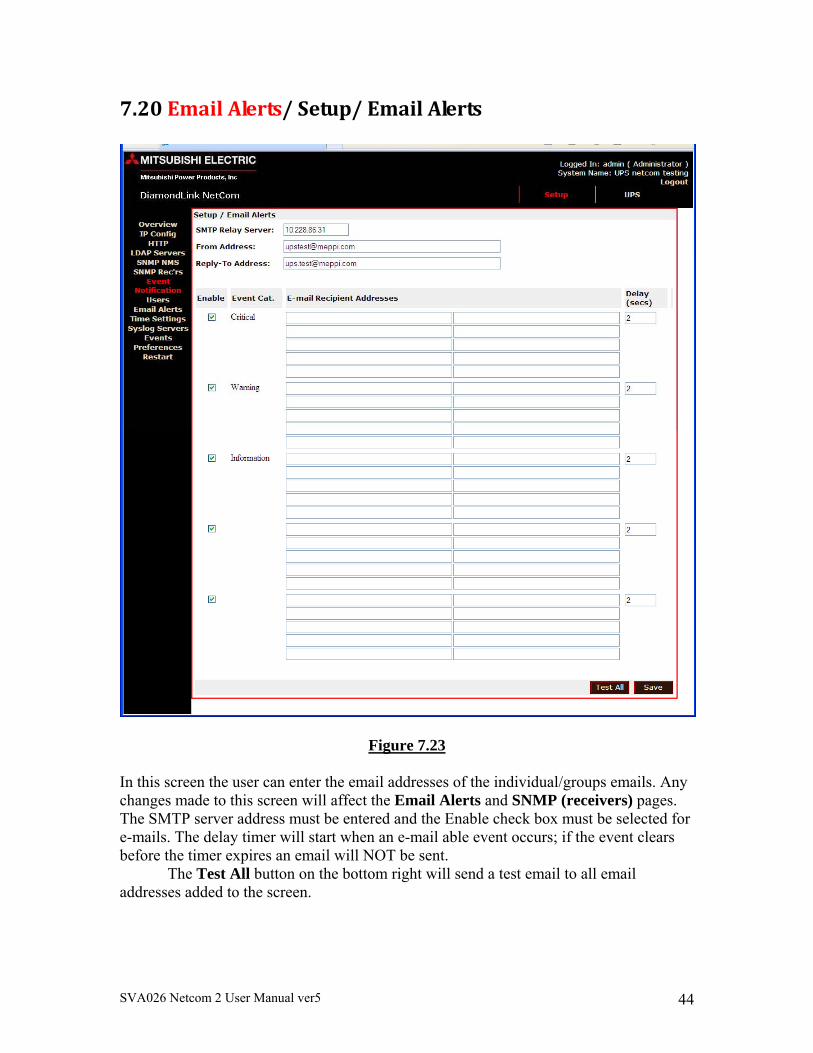
In this screen the user can enter the email addresses of the individual/groups emails. Any changes made to this screen will affect the Email Alerts and SNMP (receivers) pages. The SMTP server address must be entered and the Enable check box must be selected for e-mails. The delay timer will start when an e-mail able event occurs; if the event clears before the timer expires an email will NOT be sent. The Test All button on the bottom right will send a test email to all email addresses added to the screen.
SVA026 Netcom 2 User Manual ver5 45
7.21TimeSetting/Setup/TimeSettings
Figure 7.24
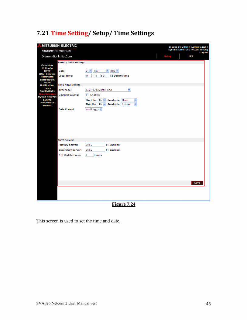
This screen is used to set the time and date.
SVA026 Netcom 2 User Manual ver5 46
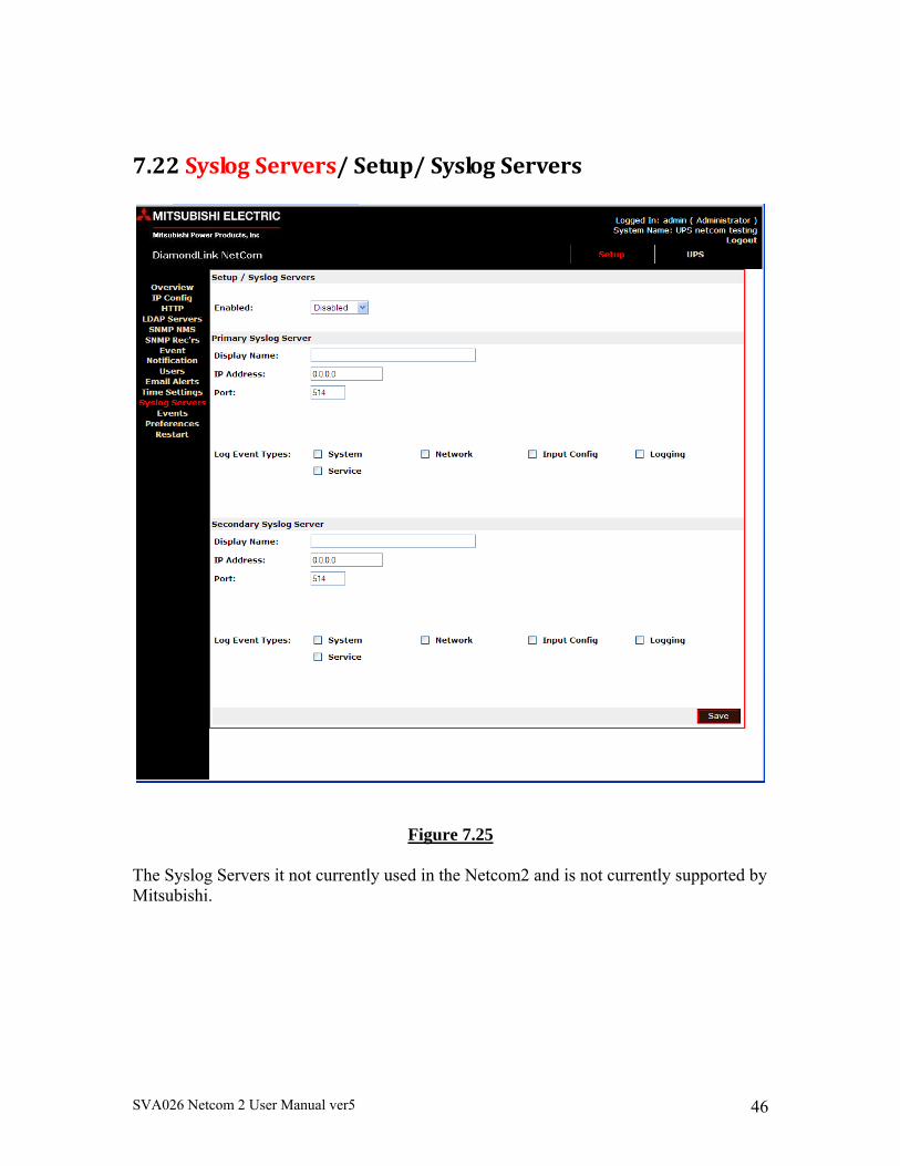
7.22SyslogServers/Setup/SyslogServers
Figure 7.25 The Syslog Servers it not currently used in the Netcom2 and is not currently supported by Mitsubishi.
SVA026 Netcom 2 User Manual ver5 47
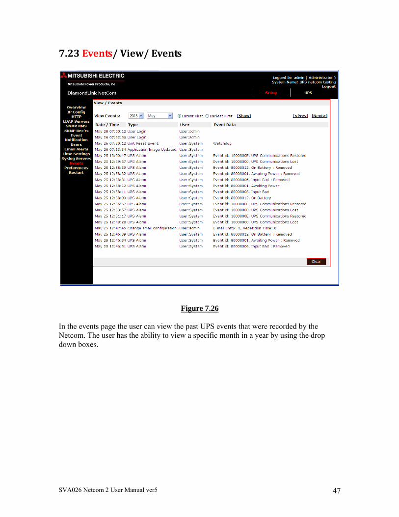
7.23Events/View/Events
Figure 7.26 In the events page the user can view the past UPS events that were recorded by the Netcom. The user has the ability to view a specific month in a year by using the drop down boxes.
SVA026 Netcom 2 User Manual ver5 48
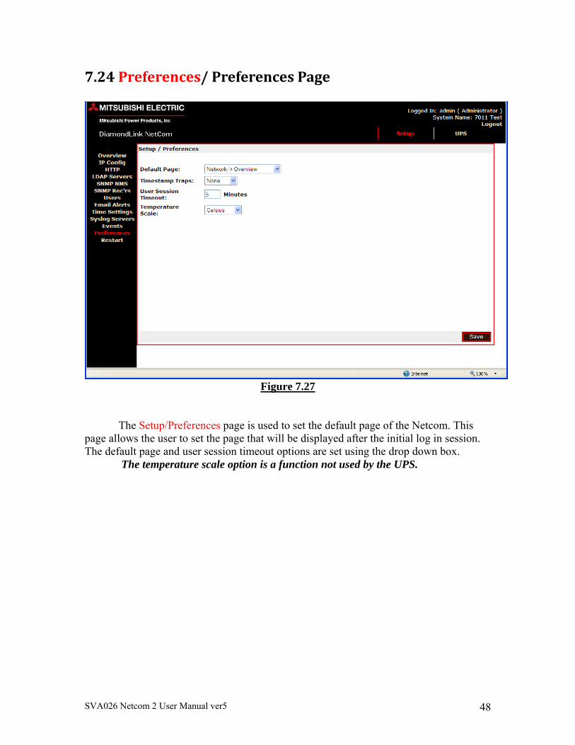
7.24Preferences/PreferencesPage
Figure 7.27
The Setup/Preferences page is used to set the default page of the Netcom. This page allows the user to set the page that will be displayed after the initial log in session. The default page and user session timeout options are set using the drop down box.
The temperature scale option is a function not used by the UPS.
SVA026 Netcom 2 User Manual ver5 49
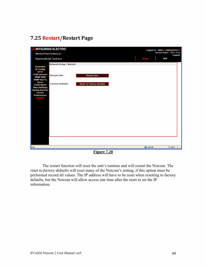
7.25Restart/RestartPage
Figure 7.28
The restart function will reset the unit’s runtime and will restart the Netcom. The reset to factory defaults will reset many of the Netcom’s setting, if this option must be performed record all values. The IP address will have to be reset when resetting to factory defaults, but the Netcom will allow access one time after the reset to set the IP information.
SVA026 Netcom 2 User Manual ver5 50
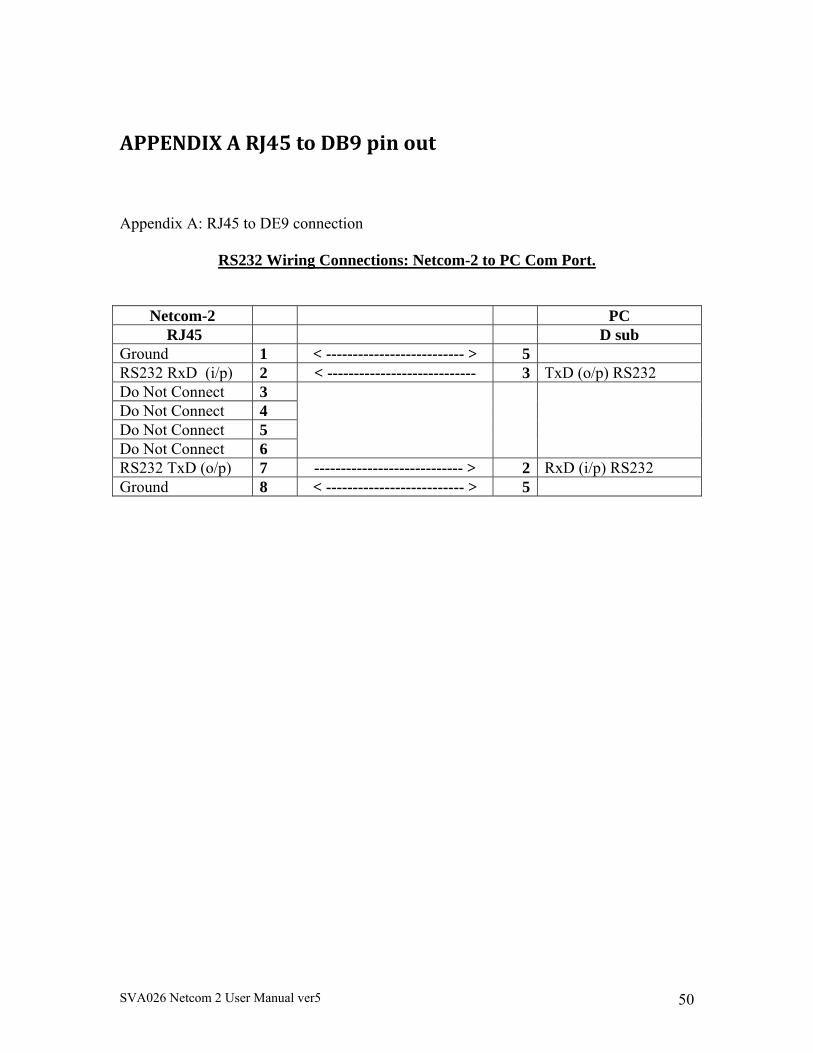
APPENDIXARJ45toDB9pinout
Appendix A: RJ45 to DE9 connection
RS232 Wiring Connections: Netcom-2 to PC Com Port.
Netcom-2 PC RJ45 D sub
Ground 1 < -------------------------- > 5 RS232 RxD (i/p) 2 < ---------------------------- 3 TxD (o/p) RS232 Do Not Connect 3 Do Not Connect 4 Do Not Connect 5 Do Not Connect 6 RS232 TxD (o/p) 7 ---------------------------- > 2 RxD (i/p) RS232 Ground 8 < -------------------------- > 5
SVA026 Netcom 2 User Manual ver5 51
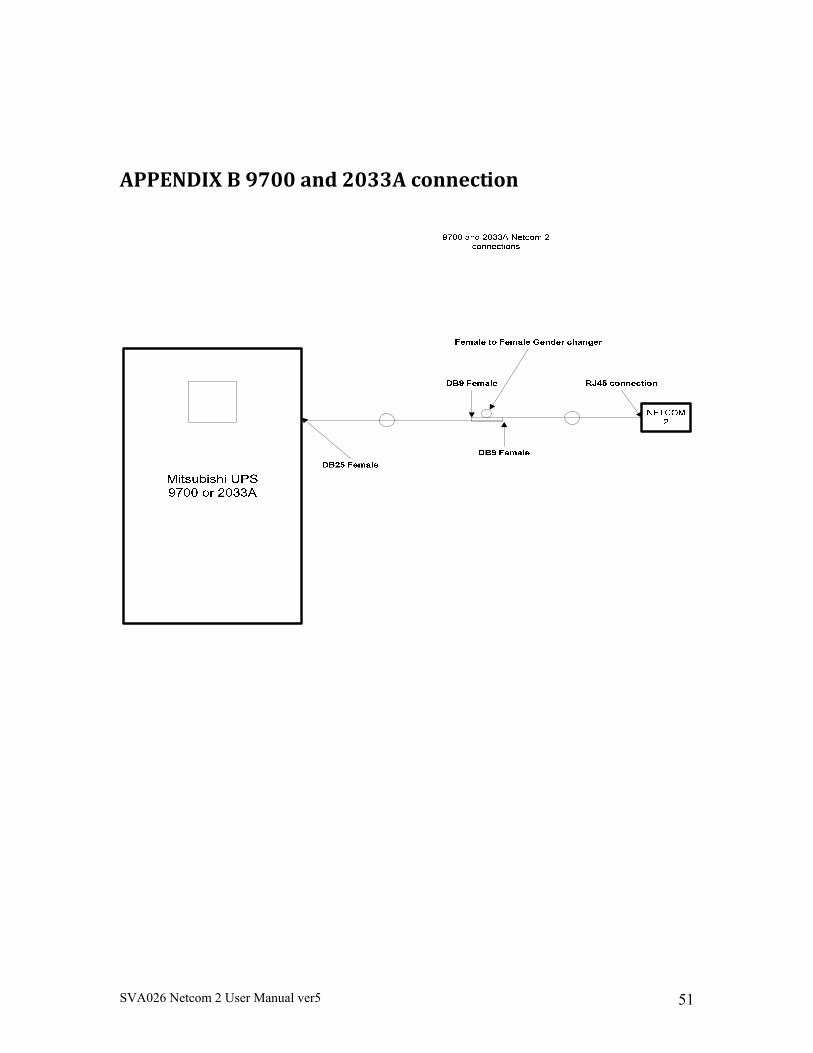
APPENDIXB9700and2033Aconnection
SVA026 Netcom 2 User Manual ver5 52
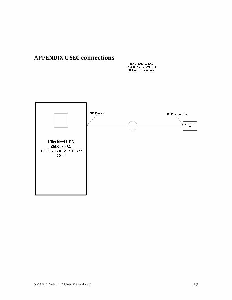
APPENDIXCSECconnections
SVA026 Netcom 2 User Manual ver5 53
APPENDIXDMIBS
Appendix B: MIB file -- Mitsubishi.mib - MIB file for Mitsubishi UPSs UPS-MIB DEFINITIONS ::= BEGIN IMPORTS TRAP-TYPE FROM RFC-1215 DisplayString FROM RFC1213-MIB OBJECT-TYPE FROM RFC-1212 Gauge, Counter, TimeTicks, mgmt FROM RFC1155-SMI ; PositiveInteger ::= INTEGER NonNegativeInteger ::= INTEGER TimeStamp ::= TimeTicks TimeInterval ::= INTEGER (0..2147483647) TestAndIncr ::= INTEGER (0..2147483647) AutonomousType ::= DisplayString Tag OBJECT IDENTIFIER ::= { enterprises 13891 } MitsubishiUPS OBJECT IDENTIFIER ::= { Tag 101 } upsIdent OBJECT IDENTIFIER ::= { MitsubishiUPS 1 } upsIdentManufacturer OBJECT-TYPE SYNTAX DisplayString ACCESS read-only STATUS mandatory DESCRIPTION "The name of the UPS manufacturer." ::= { upsIdent 1 } upsIdentModel OBJECT-TYPE SYNTAX DisplayString ACCESS read-only STATUS mandatory
SVA026 Netcom 2 User Manual ver5 54
DESCRIPTION "The UPS Model designation." ::= { upsIdent 2 } upsIdentUPSSoftwareVersion OBJECT-TYPE SYNTAX DisplayString ACCESS read-only STATUS mandatory DESCRIPTION "The UPS firmware/software version(s). This variable may or may not have the same value as upsIdentAgentSoftwareVersion in some implementations." ::= { upsIdent 3 } upsIdentAgentSoftwareVersion OBJECT-TYPE SYNTAX DisplayString ACCESS read-only STATUS mandatory DESCRIPTION "The UPS agent software version. This variable may or may not have the same value as upsIdentUPSSoftwareVersion in some implementations." ::= { upsIdent 4 } upsIdentName OBJECT-TYPE SYNTAX DisplayString ACCESS read-write STATUS mandatory DESCRIPTION "A string identifying the UPS. This object should be set by the administrator." ::= { upsIdent 5 } upsIdentAttachedDevices OBJECT-TYPE SYNTAX DisplayString ACCESS read-write STATUS mandatory DESCRIPTION "A string identifying the devices attached to the output of the UPS. This object should be set by the administrator." ::= { upsIdent 6 } upsBattery OBJECT IDENTIFIER ::= { MitsubishiUPS 2 } upsBatteryStatus OBJECT-TYPE SYNTAX INTEGER { unknown(1), batteryNormal(2), batteryLow(3), batteryDepleted(4) } ACCESS read-only STATUS mandatory DESCRIPTION
SVA026 Netcom 2 User Manual ver5 55
"The indication of the capacity remaining in the UPS batteries. A value of batteryNormal indicates a normal battery condition. A value of batteryLow indicates the remaining battery run-time will not maintain the output load for an extended period of time. A value of batteryDepleted indicates that the UPS will be unable to sustain the present load when and if the utility power is lost." ::= { upsBattery 1 } upsSecondsOnBattery OBJECT-TYPE SYNTAX NonNegativeInteger -- UNITS seconds ACCESS read-only STATUS mandatory DESCRIPTION "If the unit is on battery power, the elapsed time in seconds since the UPS last switched to battery power, or the time since the network management system was last restarted, whichever is less. Zero shall be returned if the unit is not on battery power." ::= { upsBattery 2 } upsEstimatedMinutesRemaining OBJECT-TYPE SYNTAX PositiveInteger -- UNITS minutes ACCESS read-only STATUS mandatory DESCRIPTION "An estimate of the time in minutes until the battery is depleted under the present load conditions if the utility power is off and remains off, or if it were to be lost and remain off." ::= { upsBattery 3 } upsEstimatedChargeRemaining OBJECT-TYPE SYNTAX INTEGER -- UNITS percent ACCESS read-only STATUS mandatory DESCRIPTION "An estimate of the battery charge remaining expressed as a percent of full charge." ::= { upsBattery 4 } upsBatteryVoltage OBJECT-TYPE SYNTAX NonNegativeInteger -- UNITS 0.1 Volt DC ACCESS read-only STATUS mandatory DESCRIPTION "The magnitude of the present battery voltage (0.1 Volt DC)."
SVA026 Netcom 2 User Manual ver5 56
::= { upsBattery 5 } upsBatteryCurrent OBJECT-TYPE SYNTAX INTEGER (-2147483648..2147483647) -- UNITS 0.1 Amp DC ACCESS read-only STATUS mandatory DESCRIPTION "The present battery current (0.1 Amp DC)." ::= { upsBattery 6 } upsBatteryTemperature OBJECT-TYPE SYNTAX INTEGER (-2147483648..2147483647) -- UNITS degrees Centigrade ACCESS read-only STATUS mandatory DESCRIPTION "The ambient temperature at or near the UPS Battery casing (degrees Centigrade)." ::= { upsBattery 7 } upsInput OBJECT IDENTIFIER ::= { MitsubishiUPS 3 } upsInputLineBads OBJECT-TYPE SYNTAX Counter ACCESS read-only STATUS mandatory DESCRIPTION "A count of the number of times the input entered an out-of-tolerance condition as defined by the manufacturer. This count is incremented by one each time the input transitions from zero out-of-tolerance lines to one or more input lines out-of-tolerance." ::= { upsInput 1 } upsInputNumLines OBJECT-TYPE SYNTAX NonNegativeInteger ACCESS read-only STATUS mandatory DESCRIPTION "The number of input lines utilized in this device. This variable indicates the number of rows in the input table." ::= { upsInput 2 } upsInputTable OBJECT-TYPE SYNTAX SEQUENCE OF UpsInputEntry ACCESS not-accessible STATUS mandatory DESCRIPTION "A list of input table entries. The number of entries is given by the value of upsInputNumLines." ::= { upsInput 3 } upsInputEntry OBJECT-TYPE SYNTAX UpsInputEntry ACCESS not-accessible STATUS mandatory DESCRIPTION
SVA026 Netcom 2 User Manual ver5 57
"An entry containing information applicable to a particular input line." INDEX { upsInputLineIndex } ::= { upsInputTable 1 } UpsInputEntry ::= SEQUENCE { upsInputLineIndex PositiveInteger, upsInputFrequency NonNegativeInteger, upsInputVoltage NonNegativeInteger, upsInputCurrent NonNegativeInteger, upsInputTruePower NonNegativeInteger } upsInputLineIndex OBJECT-TYPE SYNTAX PositiveInteger ACCESS read-only STATUS mandatory DESCRIPTION "The input line identifier." ::= { upsInputEntry 1 } upsInputFrequency OBJECT-TYPE SYNTAX NonNegativeInteger -- UNITS 0.1 Hertz ACCESS read-only STATUS mandatory DESCRIPTION "The present input frequency (0.1 Hertz)." ::= { upsInputEntry 2 } upsInputVoltage OBJECT-TYPE SYNTAX NonNegativeInteger -- UNITS 0.1 RMS Volt ACCESS read-only STATUS mandatory DESCRIPTION "The magnitude of the present input voltage (0.1 RMS Volt)." ::= { upsInputEntry 3 } upsInputCurrent OBJECT-TYPE SYNTAX NonNegativeInteger -- UNITS 0.1 RMS Amp ACCESS read-only STATUS mandatory DESCRIPTION "The magnitude of the present input current (0.1 RMS Amp)." ::= { upsInputEntry 4 } upsInputTruePower OBJECT-TYPE SYNTAX NonNegativeInteger -- UNITS Watts ACCESS read-only STATUS mandatory DESCRIPTION "The magnitude of the present input true power (watts)." ::= { upsInputEntry 5 } upsOutput OBJECT IDENTIFIER ::= { MitsubishiUPS 4 }
SVA026 Netcom 2 User Manual ver5 58
upsOutputSource OBJECT-TYPE SYNTAX INTEGER { other(1), none(2), normal(3), bypass(4), battery(5), booster(6), reducer(7) } ACCESS read-only STATUS mandatory DESCRIPTION "The present source of output power. A value of none (2) indicates there is no source of output power (and therefore no output power), for example, the system has opened the output breaker." ::= { upsOutput 1 } upsOutputFrequency OBJECT-TYPE SYNTAX NonNegativeInteger -- UNITS 0.1 Hertz ACCESS read-only STATUS mandatory DESCRIPTION "The present output frequency (0.1 Hertz)." ::= { upsOutput 2 } upsOutputNumLines OBJECT-TYPE SYNTAX NonNegativeInteger ACCESS read-only STATUS mandatory DESCRIPTION "The number of output lines utilized in this device. This variable indicates the number of rows in the output table." ::= { upsOutput 3 } upsOutputTable OBJECT-TYPE SYNTAX SEQUENCE OF UpsOutputEntry ACCESS not-accessible STATUS mandatory DESCRIPTION "A list of output table entries. The number of entries is given by the value of upsOutputNumLines." ::= { upsOutput 4 } upsOutputEntry OBJECT-TYPE SYNTAX UpsOutputEntry ACCESS not-accessible STATUS mandatory DESCRIPTION "An entry containing information applicable to a particular output line." INDEX { upsOutputLineIndex } ::= { upsOutputTable 1 }
SVA026 Netcom 2 User Manual ver5 59
UpsOutputEntry ::= SEQUENCE { upsOutputLineIndex PositiveInteger, upsOutputVoltage NonNegativeInteger, upsOutputCurrent NonNegativeInteger, upsOutputPower NonNegativeInteger, upsOutputPercentLoad INTEGER } upsOutputLineIndex OBJECT-TYPE SYNTAX PositiveInteger ACCESS read-only STATUS mandatory DESCRIPTION "The output line identifier." ::= { upsOutputEntry 1 } upsOutputVoltage OBJECT-TYPE SYNTAX NonNegativeInteger -- UNITS 0.1 RMS Volts ACCESS read-only STATUS mandatory DESCRIPTION "The present output voltage (0.1 RMS Volt)." ::= { upsOutputEntry 2 } upsOutputCurrent OBJECT-TYPE SYNTAX NonNegativeInteger -- UNITS 0.1 RMS Amp ACCESS read-only STATUS mandatory DESCRIPTION "The present output current (0.1 RMS Amp)." ::= { upsOutputEntry 3 } upsOutputPower OBJECT-TYPE SYNTAX NonNegativeInteger -- UNITS Watts ACCESS read-only STATUS mandatory DESCRIPTION "The present output true power (watts)." ::= { upsOutputEntry 4 } upsOutputPercentLoad OBJECT-TYPE SYNTAX INTEGER -- UNITS percent ACCESS read-only STATUS mandatory DESCRIPTION "The percentage of the UPS power capacity presently being used on this output line (the greater of the percent load of true power capacity and the percent load of VA." ::= { upsOutputEntry 5 } upsBypass OBJECT IDENTIFIER ::= { MitsubishiUPS 5 } upsBypassFrequency OBJECT-TYPE SYNTAX NonNegativeInteger -- UNITS 0.1 Hertz ACCESS read-only
SVA026 Netcom 2 User Manual ver5 60
STATUS mandatory DESCRIPTION "The present bypass frequency." ::= { upsBypass 1 } upsBypassNumLines OBJECT-TYPE SYNTAX NonNegativeInteger ACCESS read-only STATUS mandatory DESCRIPTION "The number of bypass lines utilized in this device. This entry indicates the number of rows in the bypass table." ::= { upsBypass 2 } upsBypassTable OBJECT-TYPE SYNTAX SEQUENCE OF UpsBypassEntry ACCESS not-accessible STATUS mandatory DESCRIPTION "A list of bypass table entries. The number of entries is given by the value of upsBypassNumLines." ::= { upsBypass 3 } upsBypassEntry OBJECT-TYPE SYNTAX UpsBypassEntry ACCESS not-accessible STATUS mandatory DESCRIPTION "An entry containing information applicable to a particular bypass input." INDEX { upsBypassLineIndex } ::= { upsBypassTable 1 } UpsBypassEntry ::= SEQUENCE { upsBypassLineIndex PositiveInteger, upsBypassVoltage NonNegativeInteger, upsBypassCurrent NonNegativeInteger, upsBypassPower NonNegativeInteger } upsBypassLineIndex OBJECT-TYPE SYNTAX PositiveInteger ACCESS read-only STATUS mandatory DESCRIPTION "The bypass line identifier." ::= { upsBypassEntry 1 } upsBypassVoltage OBJECT-TYPE SYNTAX NonNegativeInteger -- UNITS 0.1 RMS Volts ACCESS read-only STATUS mandatory DESCRIPTION "The present bypass voltage (0.1 RMS Volt)." ::= { upsBypassEntry 2 }
SVA026 Netcom 2 User Manual ver5 61
upsBypassCurrent OBJECT-TYPE SYNTAX NonNegativeInteger -- UNITS 0.1 RMS Amp ACCESS read-only STATUS mandatory DESCRIPTION "The present bypass current (0.1 RMS Amp)." ::= { upsBypassEntry 3 } upsBypassPower OBJECT-TYPE SYNTAX NonNegativeInteger -- UNITS Watts ACCESS read-only STATUS mandatory DESCRIPTION "The present true power conveyed by the bypass (watts)." ::= { upsBypassEntry 4 } upsAlarm OBJECT IDENTIFIER ::= { MitsubishiUPS 6 } upsAlarmsPresent OBJECT-TYPE SYNTAX Gauge ACCESS read-only STATUS mandatory DESCRIPTION "The present number of active alarm conditions." ::= { upsAlarm 1 } upsAlarmTable OBJECT-TYPE SYNTAX SEQUENCE OF UpsAlarmEntry ACCESS not-accessible STATUS mandatory DESCRIPTION "A list of alarm table entries. Alarms are named by an OBJECT IDENTIFIER, upsAlarmDescr, to allow a single table to reflect well known alarms plus alarms defined by a particular implementation, i.e., as documented in the private enterprise MIB definition for the device. No two rows will have the same value of upsAlarmDescr, since alarms define conditions. In order to meet this requirement, care should be taken in the definition of alarm conditions to insure that a system cannot enter the same condition multiple times simultaneously. The number of rows in the table at any given time is reflected by the value of upsAlarmsPresent." ::= { upsAlarm 2 } upsAlarmEntry OBJECT-TYPE SYNTAX UpsAlarmEntry ACCESS not-accessible STATUS mandatory DESCRIPTION "An entry containing information applicable to a particular alarm." INDEX { upsAlarmId } ::= { upsAlarmTable 1 }
SVA026 Netcom 2 User Manual ver5 62
UpsAlarmEntry ::= SEQUENCE { upsAlarmId PositiveInteger, upsAlarmDescr AutonomousType, upsAlarmTime TimeStamp } upsAlarmId OBJECT-TYPE SYNTAX PositiveInteger ACCESS read-only STATUS mandatory DESCRIPTION "A unique identifier for an alarm condition. This value must remain constant." ::= { upsAlarmEntry 1 } upsAlarmDescr OBJECT-TYPE SYNTAX AutonomousType ACCESS read-only STATUS mandatory DESCRIPTION "A reference to an alarm description object. The object referenced should not be accessible, but rather be used to provide a unique description of the alarm condition." ::= { upsAlarmEntry 2 } upsAlarmTime OBJECT-TYPE SYNTAX TimeStamp ACCESS read-only STATUS mandatory DESCRIPTION "The value of sysUpTime when the alarm condition was detected. If the alarm condition was detected at the time of agent startup and presumably existed before agent startup, the value of upsAlarmTime shall equal 0." ::= { upsAlarmEntry 3 } upsAlarmID OBJECT-TYPE SYNTAX INTEGER ACCESS read-only STATUS mandatory DESCRIPTION "A unique identifier for an alarm condition. This value must remain constant." ::= { upsAlarm 4 } upsAlarmDESCR OBJECT-TYPE SYNTAX DisplayString (SIZE(0..63)) ACCESS read-only STATUS mandatory DESCRIPTION "A reference to an alarm description object. The object references should not be accessible, but rather be used to provide a unique description of the alarm condition." ::= { upsAlarm 5 }
SVA026 Netcom 2 User Manual ver5 63
upsWellKnownAlarms OBJECT IDENTIFIER ::= { upsAlarm 3 } upsAlarmBatteryBad OBJECT-TYPE SYNTAX INTEGER ACCESS read-only STATUS mandatory DESCRIPTION "One or more batteries have been determined to require replacement." ::= { upsWellKnownAlarms 1 } upsAlarmOnBattery OBJECT-TYPE SYNTAX INTEGER ACCESS read-only STATUS mandatory DESCRIPTION "The UPS is drawing power from the batteries." ::= { upsWellKnownAlarms 2 } upsAlarmLowBattery OBJECT-TYPE SYNTAX INTEGER ACCESS read-only STATUS mandatory DESCRIPTION "The remaining battery run-time is less than or equal to upsConfigLowBattTime." ::= { upsWellKnownAlarms 3 } upsAlarmDepletedBattery OBJECT-TYPE SYNTAX INTEGER ACCESS read-only STATUS mandatory DESCRIPTION "The UPS will be unable to sustain the present load when and if the utility power is lost." ::= { upsWellKnownAlarms 4 } upsAlarmTempBad OBJECT-TYPE SYNTAX INTEGER ACCESS read-only STATUS mandatory DESCRIPTION "A temperature is out of tolerance." ::= { upsWellKnownAlarms 5 } upsAlarmInputBad OBJECT-TYPE SYNTAX INTEGER ACCESS read-only STATUS mandatory DESCRIPTION "An input condition is out of tolerance." ::= { upsWellKnownAlarms 6 } upsAlarmOutputBad OBJECT-TYPE SYNTAX INTEGER ACCESS read-only STATUS mandatory
SVA026 Netcom 2 User Manual ver5 64
DESCRIPTION "An output condition (other than OutputOverload) is out of tolerance." ::= { upsWellKnownAlarms 7 } upsAlarmOutputOverload OBJECT-TYPE SYNTAX INTEGER ACCESS read-only STATUS mandatory DESCRIPTION "The output load exceeds the UPS output capacity." ::= { upsWellKnownAlarms 8 } upsAlarmOnBypass OBJECT-TYPE SYNTAX INTEGER ACCESS read-only STATUS mandatory DESCRIPTION "The Bypass is presently engaged on the UPS." ::= { upsWellKnownAlarms 9 } upsAlarmBypassBad OBJECT-TYPE SYNTAX INTEGER ACCESS read-only STATUS mandatory DESCRIPTION "The Bypass is out of tolerance." ::= { upsWellKnownAlarms 10 } upsAlarmOutputOffAsRequested OBJECT-TYPE SYNTAX INTEGER ACCESS read-only STATUS mandatory DESCRIPTION "The UPS has shut down as requested, i.e., the output is off." ::= { upsWellKnownAlarms 11 } upsAlarmUpsOffAsRequested OBJECT-TYPE SYNTAX INTEGER ACCESS read-only STATUS mandatory DESCRIPTION "The entire UPS has shutdown as commanded." ::= { upsWellKnownAlarms 12 } upsAlarmChargerFailed OBJECT-TYPE SYNTAX INTEGER ACCESS read-only STATUS mandatory DESCRIPTION "An uncorrected problem has been detected within the UPS charger subsystem." ::= { upsWellKnownAlarms 13 } upsAlarmUpsOutputOff OBJECT-TYPE SYNTAX INTEGER
SVA026 Netcom 2 User Manual ver5 65
ACCESS read-only STATUS mandatory DESCRIPTION "The output of the UPS is in the off state." ::= { upsWellKnownAlarms 14 } upsAlarmUpsSystemOff OBJECT-TYPE SYNTAX INTEGER ACCESS read-only STATUS mandatory DESCRIPTION "The UPS system is in the off state." ::= { upsWellKnownAlarms 15 } upsAlarmFanFailure OBJECT-TYPE SYNTAX INTEGER ACCESS read-only STATUS mandatory DESCRIPTION "The failure of one or more fans in the UPS has been detected." ::= { upsWellKnownAlarms 16 } upsAlarmFuseFailure OBJECT-TYPE SYNTAX INTEGER ACCESS read-only STATUS mandatory DESCRIPTION "The failure of one or more fuses has been detected." ::= { upsWellKnownAlarms 17 } upsAlarmGeneralFault OBJECT-TYPE SYNTAX INTEGER ACCESS read-only STATUS mandatory DESCRIPTION "A general fault in the UPS has been detected." ::= { upsWellKnownAlarms 18 } upsAlarmDiagnosticTestFailed OBJECT-TYPE SYNTAX INTEGER ACCESS read-only STATUS mandatory DESCRIPTION "The result of the last diagnostic test indicates a failure." ::= { upsWellKnownAlarms 19 } upsAlarmCommunicationsLost OBJECT-TYPE SYNTAX INTEGER ACCESS read-only STATUS mandatory DESCRIPTION "A problem has been encountered in the communications between the agent and the UPS." ::= { upsWellKnownAlarms 20 }
SVA026 Netcom 2 User Manual ver5 66
upsAlarmAwaitingPower OBJECT-TYPE SYNTAX INTEGER ACCESS read-only STATUS mandatory DESCRIPTION "The UPS output is off and the UPS is awaiting the return of input power." ::= { upsWellKnownAlarms 21 } upsAlarmShutdownPending OBJECT-TYPE SYNTAX INTEGER ACCESS read-only STATUS mandatory DESCRIPTION "A upsShutdownAfterDelay countdown is underway." ::= { upsWellKnownAlarms 22 } upsAlarmShutdownImminent OBJECT-TYPE SYNTAX INTEGER ACCESS read-only STATUS mandatory DESCRIPTION "The UPS will turn off power to the load in less than 5 seconds; this may be either a timed shutdown or a low battery shutdown." ::= { upsWellKnownAlarms 23 } upsAlarmTestInProgress OBJECT-TYPE SYNTAX INTEGER ACCESS read-only STATUS mandatory DESCRIPTION "A test is in progress, as initiated and indicated by the Test Group. Tests initiated via other implementation-specific mechanisms can indicate the presence of the testing in the alarm table, if desired, via a OBJECT-TYPE macro in the MIB document specific to that implementation and are outside the scope of this OBJECT-TYPE." ::= { upsWellKnownAlarms 24 } upsTest OBJECT IDENTIFIER ::= { MitsubishiUPS 7 } upsTestId OBJECT-TYPE SYNTAX OBJECT IDENTIFIER ACCESS read-write STATUS mandatory DESCRIPTION "The test named by an OBJECT IDENTIFIER which allows a standard mechanism for the initiation of a test, including the well known tests identified in this document." ::= { upsTest 1 } upsTestSpinLock OBJECT-TYPE SYNTAX TestAndIncr ACCESS read-write
SVA026 Netcom 2 User Manual ver5 67
STATUS mandatory DESCRIPTION "A spin lock on the test subsystem." ::= { upsTest 2 } upsTestResultsSummary OBJECT-TYPE SYNTAX INTEGER { donePass(1), doneWarning(2), doneError(3), aborted(4), inProgress(5), noTestsInitiated(6) } ACCESS read-only STATUS mandatory DESCRIPTION "The results of the current or last UPS diagnostics test performed. The values for donePass(1), doneWarning(2), and doneError(3) indicate that the test completed either successfully, with a warning, or with an error, respectively. The value aborted(4) is returned for tests which are aborted by setting the value of upsTestId to upsTestAbortTestInProgress. Tests which have not yet concluded are indicated by inProgress(5). The value noTestsInitiated(6) indicates that no previous test results are available, such as is the case when no tests have been run since the last reinitialization of the network management subsystem and the system has no provision for non- volatile storage of test results." ::= { upsTest 3 } upsTestResultsDetail OBJECT-TYPE SYNTAX DisplayString ACCESS read-only STATUS mandatory DESCRIPTION "Additional information about upsTestResultsSummary. If no additional information available, a zero length string is returned." ::= { upsTest 4 } upsTestStartTime OBJECT-TYPE SYNTAX TimeStamp ACCESS read-only STATUS mandatory DESCRIPTION "The value of sysUpTime at the time the test in progress was initiated, or, if no test is in progress, the time the previous test was initiated. If the value of upsTestResultsSummary is noTestsInitiated(6), upsTestStartTime has the value 0." ::= { upsTest 5 } upsTestElapsedTime OBJECT-TYPE
SVA026 Netcom 2 User Manual ver5 68
SYNTAX TimeInterval ACCESS read-only STATUS mandatory DESCRIPTION "The amount of time, in TimeTicks, since the test in progress was initiated, or, if no test is in progress, the previous test took to complete. If the value of upsTestResultsSummary is noTestsInitiated(6), upsTestElapsedTime has the value 0." ::= { upsTest 6 } upsWellKnownTests OBJECT IDENTIFIER ::= { upsTest 7 } upsTestNoTestsInitiated OBJECT-TYPE SYNTAX INTEGER ACCESS read-only STATUS mandatory DESCRIPTION "No tests have been initiated and no test is in progress." ::= { upsWellKnownTests 1 } upsTestAbortTestInProgress OBJECT-TYPE SYNTAX INTEGER ACCESS read-only STATUS mandatory DESCRIPTION "The test in progress is to be aborted / the test in progress was aborted." ::= { upsWellKnownTests 2 } upsTestGeneralSystemsTest OBJECT-TYPE SYNTAX INTEGER ACCESS read-only STATUS mandatory DESCRIPTION "The manufacturer's standard test of UPS device systems." ::= { upsWellKnownTests 3 } upsTestQuickBatteryTest OBJECT-TYPE SYNTAX INTEGER ACCESS read-only STATUS mandatory DESCRIPTION "A test that is sufficient to determine if the battery needs replacement." ::= { upsWellKnownTests 4 } upsTestDeepBatteryCalibration OBJECT-TYPE SYNTAX INTEGER ACCESS read-only STATUS mandatory DESCRIPTION "The system is placed on battery to a discharge level, set by the manufacturer, sufficient to determine battery replacement and battery run-time with a high degree of confidence. WARNING: this test will leave the battery in a low charge state and will require
SVA026 Netcom 2 User Manual ver5 69
time for recharging to a level sufficient to provide normal battery duration for the protected load." ::= { upsWellKnownTests 5 } upsControl OBJECT IDENTIFIER ::= { MitsubishiUPS 8 } upsShutdownType OBJECT-TYPE SYNTAX INTEGER { output(1), system(2) } ACCESS read-write STATUS mandatory DESCRIPTION "This object determines the nature of the action to be taken at the time when the countdown of the upsShutdownAfterDelay and upsRebootWithDuration objects reaches zero. Setting this object to output(1) indicates that shutdown requests should cause only the output of the UPS to turn off. Setting this object to system(2) indicates that shutdown requests will cause the entire UPS system to turn off." ::= { upsControl 1 } upsShutdownAfterDelay OBJECT-TYPE SYNTAX INTEGER -- UNITS seconds ACCESS read-write STATUS mandatory DESCRIPTION "Setting this object will shutdown (i.e., turn off) either the UPS output or the UPS system (as determined by the value of upsShutdownType at the time of shutdown) after the indicated number of seconds, or less if the UPS batteries become depleted. Setting this object to 0 will cause the shutdown to occur immediately. Setting this object to -1 will abort the countdown. If the system is already in the desired state at the time the countdown reaches 0, then nothing will happen. That is, there is no additional action at that time if upsShutdownType = system and the system is already off. Similarly, there is no additional action at that time if upsShutdownType = output and the output is already off. When read, upsShutdownAfterDelay will return the number of seconds remaining until shutdown, or -1 if no shutdown countdown is in effect. On some systems, if the agent is restarted while a shutdown countdown is in effect, the countdown may be aborted. Sets to this object override any upsShutdownAfterDelay already in effect." ::= { upsControl 2 } upsStartupAfterDelay OBJECT-TYPE SYNTAX INTEGER -- UNITS seconds ACCESS read-write
SVA026 Netcom 2 User Manual ver5 70
STATUS mandatory DESCRIPTION "Setting this object will start the output after the indicated number of seconds, including starting the UPS, if necessary. Setting this object to 0 will cause the startup to occur immediately. Setting this object to -1 will abort the countdown. If the output is already on at the time the countdown reaches 0, then nothing will happen. Sets to this object override the effect of any upsStartupAfterDelay countdown or upsRebootWithDuration countdown in progress. When read, upsStartupAfterDelay will return the number of seconds until startup, or -1 if no startup countdown is in effect. If the countdown expires during a utility failure, the startup shall not occur until the utility power is restored. On some systems, if the agent is restarted while a startup countdown is in effect, the countdown is aborted." ::= { upsControl 3 } upsRebootWithDuration OBJECT-TYPE SYNTAX INTEGER -- UNITS seconds ACCESS read-write STATUS mandatory DESCRIPTION "Setting this object will immediately shutdown (i.e., turn off) either the UPS output or the UPS system (as determined by the value of upsShutdownType at the time of shutdown) for a period equal to the indicated number of seconds, after which time the output will be started, including starting the UPS, if necessary. If the number of seconds required to perform the request is greater than the requested duration, then the requested shutdown and startup cycle shall be performed in the minimum time possible, but in no case shall this require more than the requested duration plus 60 seconds. When read, upsRebootWithDuration shall return the number of seconds remaining in the countdown, or -1 if no countdown is in progress. If the startup should occur during a utility failure, the startup shall not occur until the utility power is restored." ::= { upsControl 4 } upsAutoRestart OBJECT-TYPE SYNTAX INTEGER { on(1), off(2) } ACCESS read-write STATUS mandatory DESCRIPTION "Setting this object to 'on' will cause the UPS system to restart after a shutdown if the shutdown occurred during a power loss as a result of either a
SVA026 Netcom 2 User Manual ver5 71
upsShutdownAfterDelay or an internal battery depleted condition. Setting this object to 'off' will prevent the UPS system from restarting after a shutdown until an operator manually or remotely explicitly restarts it. If the UPS is in a startup or reboot countdown, then the UPS will not restart until that delay has been satisfied." ::= { upsControl 5 } upsConfig OBJECT IDENTIFIER ::= { MitsubishiUPS 9 } upsConfigInputVoltage OBJECT-TYPE SYNTAX NonNegativeInteger -- UNITS RMS Volts ACCESS read-write STATUS mandatory DESCRIPTION "The magnitude of the nominal input voltage (RMS Volts). On those systems which support read-write access to this object, if there is an attempt to set this variable to a value that is not supported, the request must be rejected and the agent shall respond with an appropriate error message, i.e., badValue for SNMPv1, or inconsistentValue for SNMPv2." ::= { upsConfig 1 } upsConfigInputFreq OBJECT-TYPE SYNTAX NonNegativeInteger -- UNITS 0.1 Hertz ACCESS read-write STATUS mandatory DESCRIPTION "The nominal input frequency (0.1 Hertz). On those systems which support read-write access to this object, if there is an attempt to set this variable to a value that is not supported, the request must be rejected and the agent shall respond with an appropriate error message, i.e., badValue for SNMPv1, or inconsistentValue for SNMPv2." ::= { upsConfig 2 } upsConfigOutputVoltage OBJECT-TYPE SYNTAX NonNegativeInteger -- UNITS RMS Volts ACCESS read-write STATUS mandatory DESCRIPTION "The magnitude of the nominal output voltage (RMS Volts). On those systems which support read-write access to this object, if there is an attempt to set this variable to a value that is not supported, the request must be rejected and the agent shall respond with an appropriate error message, i.e., badValue for SNMPv1, or inconsistentValue for SNMPv2." ::= { upsConfig 3 } upsConfigOutputFreq OBJECT-TYPE SYNTAX NonNegativeInteger -- UNITS 0.1 Hertz ACCESS read-write STATUS mandatory DESCRIPTION
SVA026 Netcom 2 User Manual ver5 72
"The nominal output frequency (0.1 Hertz). On those systems which support read-write access to this object, if there is an attempt to set this variable to a value that is not supported, the request must be rejected and the agent shall respond with an appropriate error message, i.e., badValue for SNMPv1, or inconsistentValue for SNMPv2." ::= { upsConfig 4 } upsConfigOutputVA OBJECT-TYPE SYNTAX NonNegativeInteger -- UNITS Volt-Amps ACCESS read-only STATUS mandatory DESCRIPTION "The magnitude of the nominal Volt-Amp rating (Volt-Amps)." ::= { upsConfig 5 } upsConfigOutputPower OBJECT-TYPE SYNTAX NonNegativeInteger -- UNITS Watts ACCESS read-only STATUS mandatory DESCRIPTION "The magnitude of the nominal true power rating (watts)." ::= { upsConfig 6 } upsConfigLowBattTime OBJECT-TYPE SYNTAX NonNegativeInteger -- UNITS minutes ACCESS read-write STATUS mandatory DESCRIPTION "The value of upsEstimatedMinutesRemaining at which a lowBattery condition is declared. For agents which support only discrete (discontinuous) values, then the agent shall round up to the next supported value. If the requested value is larger than the largest supported value, then the largest supported value shall be selected." ::= { upsConfig 7 } upsConfigAudibleStatus OBJECT-TYPE SYNTAX INTEGER { disabled(1), enabled(2), muted(3) } ACCESS read-write STATUS mandatory DESCRIPTION "The requested state of the audible alarm. When in the disabled state, the audible alarm should never sound. The enabled state is self-describing. Setting this object to muted(3) when the audible alarm is sounding shall temporarily silence the alarm. It will remain muted until it would normally stop sounding and the value returned for read operations during this period shall equal muted(3). At the end of this period, the value shall revert to enabled(2). Writes
SVA026 Netcom 2 User Manual ver5 73
of the value muted(3) when the audible alarm is not sounding shall be accepted but otherwise shall have no effect." ::= { upsConfig 8 } upsConfigLowVoltageTransferPoint OBJECT-TYPE SYNTAX NonNegativeInteger -- UNITS RMS Volts ACCESS read-write STATUS mandatory DESCRIPTION "The minimum input line voltage (RMS Volts) allowed before the UPS system transfers to battery backup." ::= { upsConfig 9 } upsConfigHighVoltageTransferPoint OBJECT-TYPE SYNTAX NonNegativeInteger -- UNITS RMS Volts ACCESS read-write STATUS mandatory DESCRIPTION "The maximum line voltage (RMS Volts) allowed before the UPS system transfers to battery backup." ::= { upsConfig 10 } -- UPS trap information group upsTrapInfo OBJECT IDENTIFIER ::= { MitsubishiUPS 10 } trapCode OBJECT-TYPE SYNTAX Unsigned32 ACCESS read-only STATUS mandatory DESCRIPTION "A number identifying the event for that last trap that was sent." ::= { upsTrapInfo 1 } trapDescription OBJECT-TYPE SYNTAX DisplayString (SIZE (0..63)) ACCESS read-only STATUS mandatory DESCRIPTION "A string identifying the event for that last trap that was sent." ::= { upsTrapInfo 2 } -- UPS Traps -- upsTraps OBJECT IDENTIFIER ::= { Tag 101 } alarmCritical TRAP-TYPE ENTERPRISE MitsubishiUPS VARIABLES { trapCode, trapDescription } DESCRIPTION "Critical alarm." ::= 1 alarmWarning TRAP-TYPE ENTERPRISE MitsubishiUPS VARIABLES { trapCode, trapDescription }
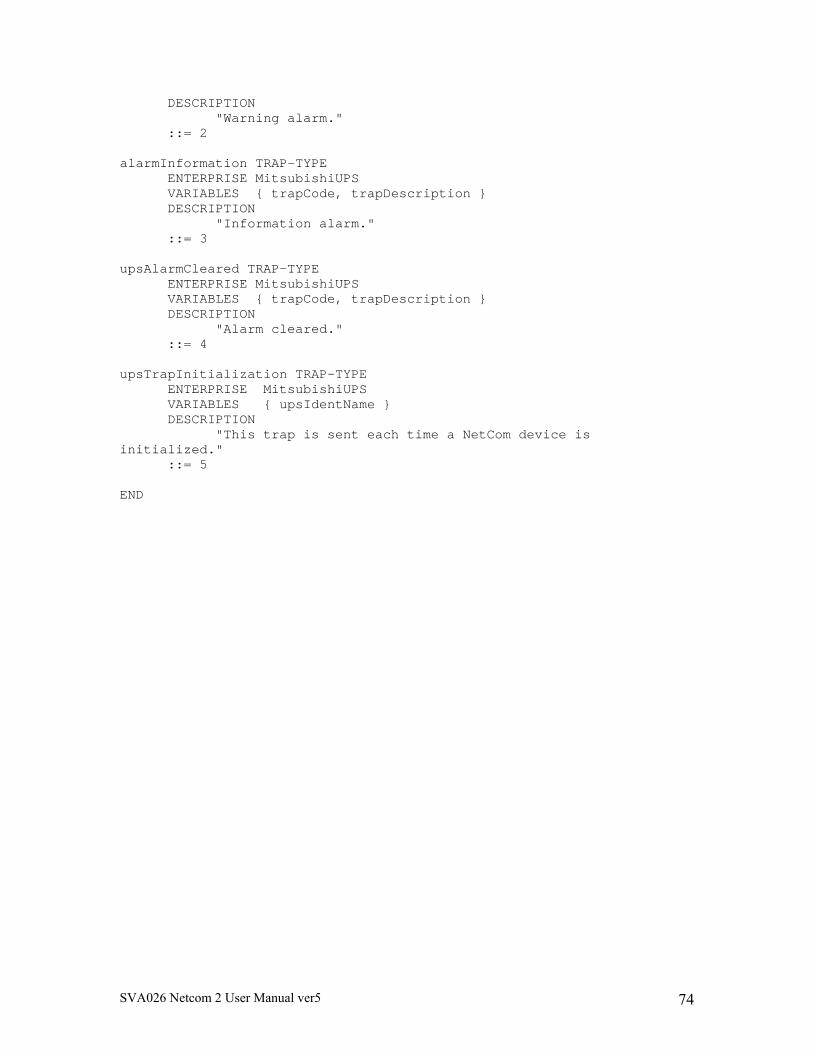
SVA026 Netcom 2 User Manual ver5 74
DESCRIPTION "Warning alarm." ::= 2 alarmInformation TRAP-TYPE ENTERPRISE MitsubishiUPS VARIABLES { trapCode, trapDescription } DESCRIPTION "Information alarm." ::= 3 upsAlarmCleared TRAP-TYPE ENTERPRISE MitsubishiUPS VARIABLES { trapCode, trapDescription } DESCRIPTION "Alarm cleared." ::= 4 upsTrapInitialization TRAP-TYPE ENTERPRISE MitsubishiUPS VARIABLES { upsIdentName } DESCRIPTION "This trap is sent each time a NetCom device is initialized." ::= 5 END