Embed Size (px)
Citation preview

User ManualUser ManualUser ManualUser ManualUser ManualUser ManualUser ManualUser ManualUser ManualUser ManualUser ManualUser ManualUser ManualUser ManualUser ManualUser ManualUser ManualUser ManualUser ManualUser ManualUser ManualUser ManualUser ManualUser ManualUser ManualUser ManualUser ManualUser ManualUser ManualUser ManualUser ManualUser ManualUser ManualUSB-COM Plus
Edition: February 2017Edition: February 2017Edition: February 2017Edition: February 2017Edition: February 2017Edition: February 2017Edition: February 2017Edition: February 2017Edition: February 2017Edition: February 2017Edition: February 2017Edition: February 2017Edition: February 2017Edition: February 2017Edition: February 2017Edition: February 2017Edition: February 2017
Tel: +49 40 528 401 0Fax: +49 40 528 401 99Web: www.visionsystems.deSupport: [email protected]

The software described in this manual is furnished under a license agreement and may be usedonly in accordance with the terms of that agreement.
Copyright Notice
Copyright © 2009-2017 Vision Systems. All rights reserved. Reproduction without permission isprohibited.
Trademarks
VScom is a registered trademark of Vision Systems GmbH. All other trademarks and brands areproperty of their rightful owners.
Disclaimer
Vision Systems reserves the right to make changes and improvements to its product without pro-viding notice.
Vision Systems provides this document “as is”, without warranty of any kind, either expressed orimplied, including, but not limited to, its particular purpose. Vision Systems reserves the rightto make improvements and/or changes to this manual, or to the products and/or the programsdescribed in this manual, at any time.
Information provided in this manual is intended to be accurate and reliable. However, VisionSystems assumes no responsibility for its use, or for any infringements on the rights of third partiesthat may result from its use.
This product might include unintentional technical or typographical errors. Changes are periodi-cally made to the information herein to correct such errors, and these changes are incorporatedinto new editions of the publication.
February 2017 USB-COM Plus User Manual 2

Contents
Contents
1. Overview 6
2. Introduction 62.1. Features . . . . . . . . . . . . . . . . . . . . . . . . . . . . . . . . . . . . . . . . . . . 62.2. Product Specifications . . . . . . . . . . . . . . . . . . . . . . . . . . . . . . . . . . . 7
2.2.1. VScom USB-COM Plus Mini and USB-COM Plus Mini ISO . . . . . . . . . 82.2.2. VScom USB-COM Plus and USB-COM Plus ISO . . . . . . . . . . . . . . . . 82.2.3. VScom USB-2COM Plus and USB-2COM Plus ISO . . . . . . . . . . . . . . 92.2.4. VScom USB-4COM Plus and USB-4COM Plus ISO . . . . . . . . . . . . . . 102.2.5. VScom USB-8COM Plus and USB-8COM Plus ISO . . . . . . . . . . . . . . 112.2.6. VScom USB-16COM Plus . . . . . . . . . . . . . . . . . . . . . . . . . . . . . 12
2.3. Packing List . . . . . . . . . . . . . . . . . . . . . . . . . . . . . . . . . . . . . . . . . 122.4. Optional Accessories . . . . . . . . . . . . . . . . . . . . . . . . . . . . . . . . . . . . 13
2.4.1. Mounting Options . . . . . . . . . . . . . . . . . . . . . . . . . . . . . . . . . 132.4.1.1. Warning: . . . . . . . . . . . . . . . . . . . . . . . . . . . . . . . . . 13
2.4.2. Power Options . . . . . . . . . . . . . . . . . . . . . . . . . . . . . . . . . . . 132.4.3. Connection Options . . . . . . . . . . . . . . . . . . . . . . . . . . . . . . . . 13
2.5. About this Manual . . . . . . . . . . . . . . . . . . . . . . . . . . . . . . . . . . . . . 13
3. The Drivers for Windows 143.1. Install Drivers from Windows Update (Automatic) . . . . . . . . . . . . . . . . . . . 143.2. Install Drivers by Pre-Installation Executable (Offline) . . . . . . . . . . . . . . . . . 17
3.2.1. Check Installation of the Drivers . . . . . . . . . . . . . . . . . . . . . . . . . 203.2.2. Uninstall Drivers . . . . . . . . . . . . . . . . . . . . . . . . . . . . . . . . . . 20
3.3. Configure the Serial Ports . . . . . . . . . . . . . . . . . . . . . . . . . . . . . . . . . 213.3.1. Rename the Serial Port . . . . . . . . . . . . . . . . . . . . . . . . . . . . . . 223.3.2. Enable faster Responses . . . . . . . . . . . . . . . . . . . . . . . . . . . . . . 223.3.3. Miscellaneous Options . . . . . . . . . . . . . . . . . . . . . . . . . . . . . . . 23
3.3.3.1. Serial Enumerator . . . . . . . . . . . . . . . . . . . . . . . . . . . . 233.3.3.2. Serial Printer . . . . . . . . . . . . . . . . . . . . . . . . . . . . . . . 233.3.3.3. Cancel if Power Off . . . . . . . . . . . . . . . . . . . . . . . . . . . 233.3.3.4. Event On Surprise Removal . . . . . . . . . . . . . . . . . . . . . . . 233.3.3.5. Set RTS On Close . . . . . . . . . . . . . . . . . . . . . . . . . . . . 233.3.3.6. Disable Modem Ctrl At Startup . . . . . . . . . . . . . . . . . . . . 23
3.4. USB-COM Plus Configurator . . . . . . . . . . . . . . . . . . . . . . . . . . . . . . . 243.5. Optimizing Data Throughput . . . . . . . . . . . . . . . . . . . . . . . . . . . . . . . 25
4. Hardware Configuration 254.1. Configuration via DIP Switches . . . . . . . . . . . . . . . . . . . . . . . . . . . . . . 25
4.1.1. Models with One and Two serial Ports . . . . . . . . . . . . . . . . . . . . . . 254.1.2. Models with Four and Eight serial Ports . . . . . . . . . . . . . . . . . . . . . 27
4.2. Configuration via Windows Software . . . . . . . . . . . . . . . . . . . . . . . . . . . 284.3. Configuration via Terminal Program . . . . . . . . . . . . . . . . . . . . . . . . . . . 30
4.3.1. Exit the Configuration (0) . . . . . . . . . . . . . . . . . . . . . . . . . . . . . 314.3.2. Show Port Configurations (1) . . . . . . . . . . . . . . . . . . . . . . . . . . . 314.3.3. Change Port Configuration (2) . . . . . . . . . . . . . . . . . . . . . . . . . . 324.3.4. Default Port Configuration (3) . . . . . . . . . . . . . . . . . . . . . . . . . . 334.3.5. Save Port Configurations (4) . . . . . . . . . . . . . . . . . . . . . . . . . . . 33
February 2017 USB-COM Plus User Manual 3

List of Figures
4.3.6. Show Configuration File (5) . . . . . . . . . . . . . . . . . . . . . . . . . . . . 334.3.7. Upload Configuration File (6) . . . . . . . . . . . . . . . . . . . . . . . . . . . 34
5. Technical Background on RS485 355.1. Transmission Technique . . . . . . . . . . . . . . . . . . . . . . . . . . . . . . . . . . 355.2. Termination . . . . . . . . . . . . . . . . . . . . . . . . . . . . . . . . . . . . . . . . . 355.3. Polarization . . . . . . . . . . . . . . . . . . . . . . . . . . . . . . . . . . . . . . . . . 365.4. 2-Wire Scheme . . . . . . . . . . . . . . . . . . . . . . . . . . . . . . . . . . . . . . . 365.5. 4-Wire Scheme . . . . . . . . . . . . . . . . . . . . . . . . . . . . . . . . . . . . . . . 375.6. On USB-COM Plus Devices . . . . . . . . . . . . . . . . . . . . . . . . . . . . . . . . 38
6. Connector Definitions 386.1. DB9 male . . . . . . . . . . . . . . . . . . . . . . . . . . . . . . . . . . . . . . . . . . 386.2. Terminal Block Adapter . . . . . . . . . . . . . . . . . . . . . . . . . . . . . . . . . . 396.3. Adapter RJ45 . . . . . . . . . . . . . . . . . . . . . . . . . . . . . . . . . . . . . . . . 39
A. History 40
List of Figures
1. VScom USB-COM Plus Mini . . . . . . . . . . . . . . . . . . . . . . . . . . . . . . . 82. VScom USB-COM Plus ISO . . . . . . . . . . . . . . . . . . . . . . . . . . . . . . . . 93. VScom USB-2COM Plus ISO . . . . . . . . . . . . . . . . . . . . . . . . . . . . . . . 94. VScom USB-4COM Plus ISO . . . . . . . . . . . . . . . . . . . . . . . . . . . . . . . 105. VScom USB-8COM Plus ISO . . . . . . . . . . . . . . . . . . . . . . . . . . . . . . . 116. VScom USB-16COM Plus . . . . . . . . . . . . . . . . . . . . . . . . . . . . . . . . . 127. Confirm Windows Update . . . . . . . . . . . . . . . . . . . . . . . . . . . . . . . . . 158. Automatic Installation . . . . . . . . . . . . . . . . . . . . . . . . . . . . . . . . . . . 169. Extract to temporary Space . . . . . . . . . . . . . . . . . . . . . . . . . . . . . . . . 1710. Start Installation . . . . . . . . . . . . . . . . . . . . . . . . . . . . . . . . . . . . . . 1811. Confirm License conditions . . . . . . . . . . . . . . . . . . . . . . . . . . . . . . . . 1812. Copy Files and Install Drivers . . . . . . . . . . . . . . . . . . . . . . . . . . . . . . . 1913. Installation finished . . . . . . . . . . . . . . . . . . . . . . . . . . . . . . . . . . . . 1914. Uninstall Drivers . . . . . . . . . . . . . . . . . . . . . . . . . . . . . . . . . . . . . . 2015. USB Serial Port Properties . . . . . . . . . . . . . . . . . . . . . . . . . . . . . . . . 2116. Advanced port options . . . . . . . . . . . . . . . . . . . . . . . . . . . . . . . . . . . 2217. Driver Configurator . . . . . . . . . . . . . . . . . . . . . . . . . . . . . . . . . . . . 2418. No Device . . . . . . . . . . . . . . . . . . . . . . . . . . . . . . . . . . . . . . . . . . 2819. One USB-8COM Plus detected . . . . . . . . . . . . . . . . . . . . . . . . . . . . . . 2920. UsbComCfg Multi-Port Selection . . . . . . . . . . . . . . . . . . . . . . . . . . . . . 3021. Open Terminal Configuration . . . . . . . . . . . . . . . . . . . . . . . . . . . . . . . 3122. Terminal Main Menu . . . . . . . . . . . . . . . . . . . . . . . . . . . . . . . . . . . . 3123. Exit Terminal Configuration . . . . . . . . . . . . . . . . . . . . . . . . . . . . . . . . 3124. Show all port configurations . . . . . . . . . . . . . . . . . . . . . . . . . . . . . . . . 3125. Change port configurations . . . . . . . . . . . . . . . . . . . . . . . . . . . . . . . . 3226. Configure a serial port . . . . . . . . . . . . . . . . . . . . . . . . . . . . . . . . . . . 3327. Saving Configuration file . . . . . . . . . . . . . . . . . . . . . . . . . . . . . . . . . . 3428. 2-wire cabling scheme . . . . . . . . . . . . . . . . . . . . . . . . . . . . . . . . . . . 3629. 4-wire cabling scheme . . . . . . . . . . . . . . . . . . . . . . . . . . . . . . . . . . . 37
February 2017 USB-COM Plus User Manual 4

List of Tables
30. DB9 male Connector . . . . . . . . . . . . . . . . . . . . . . . . . . . . . . . . . . . . 3831. Terminal Block . . . . . . . . . . . . . . . . . . . . . . . . . . . . . . . . . . . . . . . 3932. DB9-male to RJ45 . . . . . . . . . . . . . . . . . . . . . . . . . . . . . . . . . . . . . 3933. RJ45 to DB9-male . . . . . . . . . . . . . . . . . . . . . . . . . . . . . . . . . . . . . 39
List of Tables
1. Features of VScom USB-COM Plus Series . . . . . . . . . . . . . . . . . . . . . . . . 72. Serial Port Operation Modes . . . . . . . . . . . . . . . . . . . . . . . . . . . . . . . 73. Features of VScom USB-COM Plus (Single Port) . . . . . . . . . . . . . . . . . . . . 84. Features of VScom USB-COM Plus (Single Port) . . . . . . . . . . . . . . . . . . . . 85. Features of VScom USB-2COM Plus (Dual Port) . . . . . . . . . . . . . . . . . . . . 96. Features of VScom USB-4COM Plus (Quad Port) . . . . . . . . . . . . . . . . . . . . 107. Features of VScom USB-8COM Plus (Octal Port) . . . . . . . . . . . . . . . . . . . . 118. Configuration USB-COM+ Mini . . . . . . . . . . . . . . . . . . . . . . . . . . . . . 269. Configuration USB-COM+ and USB-2COM+ . . . . . . . . . . . . . . . . . . . . . . 2610. Configuration USB-4COM+ and USB-8COM+ . . . . . . . . . . . . . . . . . . . . . 2711. DB9 male Connector . . . . . . . . . . . . . . . . . . . . . . . . . . . . . . . . . . . . 3812. DB9 to RJ45 . . . . . . . . . . . . . . . . . . . . . . . . . . . . . . . . . . . . . . . . 39
February 2017 USB-COM Plus User Manual 5

2 Introduction
1. Overview
The VScom USB-COM Plus are serial port adapters, which are connected over USB port. Theyare industrial strength devices, providing different types of serial ports. The ports may operatein RS232, RS422 or RS485 mode. Ports are either configured by DIP switches or by software forfour and eight serial ports adapters. All devices come in an IP30 metal case, providing option forDIN Rail or 19” rack mounting. All connectors including serial ports, power and USB are stronglyESD protected. Each model has a standard and an galvanically isolated version, called “ISO”.For reasons of brevity USB-COM Plus are referred to as USB-COM+, as used throughout in thismanual.
The supplied drivers for Windows operating systems install the ports into the Windows API, sothey appear as the standard Com ports. All applications capable to handle a serial port can controlthe USB-COM+ devices in the same way as they control the genuine ports Com1 and Com2 ofa PC. On Linux1 systems the serial ports are installed as /dev/ttyUSBx; similar drivers exist forother operating systems.
The driver allows to configure the serial ports for bitrates of up to 3Mbit/s2. In RS232 modethe bitrate is limited to 1Mbit/s. Given the very high maximum speed, the USB-COM+ allowsgenerating many different bitrates in lower ranges. In fact every single bitrate from 185 bps up to921,600 bps (1Mbps) could be chosen as transmission speed. Above 1Mbps range many dedicatedbitrates can be also used.
The interface to the host PC is USB 2.0, Full Speed or High Speed where required.
2. Introduction
This manual describes the hardware of VScom USB-COM Plus serial port adapters. Also theWindows driver for the USB-COM+ is described in detail.
2.1. Features
• USB 2.0 High Speed or Full Speed
• Configuration serial ports modes: by DIP switches and/or by software
• Supports RS232, RS422 or RS485
• Termination resistors for RS422 or RS485automatically
• UART FIFO buffers: 128 Byte
• Max speed 3.0 Mbit/s (or 12 Mbit/s)
• Drivers for Windows™ operating system
• Supported by Linux, Mac OS X, and Windows CE on several platforms.
1Generally with Kernel 3.0.0-19 and above212Mbps on four and eight port models
February 2017 USB-COM Plus User Manual 6

2 Introduction
2.2. Product Specifications
All USB-COM+ models have similar properties. Most important difference is the number of serialports. The maximum speed is 3Mbit/s or 12Mbit/s, which may be used in RS422 or RS485 modeRS232 is limited to 1Mbit/s.
Hostinterface
USB 2.0 Full Speed or High SpeedConnector Type B
Serial Ports 1, 2, 4, 8 RS232 / RS422 / RS485
Signals
RS232 RxD,TxD, RTS,CTS, DTR,DSR, DCD, GNDRS232 isolated RxD,TxD, RTS,CTS, GNDRS422 / RS485 Tx±, Rx±, GNDRS485 Data±
Max.Bitrates
3.0 Mbit/s RS422 and RS485921.6 kbit/s RS232 (1Mbit/s)
Serialconfigurations
Data bits 7, 8Parity None, Odd, Even, Mark, SpaceStop bits 1, 2
FIFO size 128 Bytes At least, for Transmit and Receive each
LEDData Transmit/Green and
Receive/Orange for each portReady GreenPower Red
Protection All ConnectorsESD protected
Compliant with IEC 61000-4-2 ESD 8kV contact / 16kVair discharge
Table 1: Features of VScom USB-COM Plus Series
Each of the serial ports may be used in 4 different operation modes as listed below.
Mode CommentRS485 “2w” Half-Duplex, Transmitter activates by automaticRS485 “4w” Full-Duplex, Transmitter activates by automaticRS422 Full-Duplex, Transmitter permanent activeRS232
Table 2: Serial Port Operation Modes
RS422 is a Full-Duplex mode by definition, RS485 may be used in Half- or Full-Duplex. Half-Duplex is also known as “2 wire” and denoted as “2w” here, while “4w” specifies the “4 wire”Full-Duplex mode.
For RS485 mode it is important to switch off Tx lines of the device immediately after end-of-transmission, enabling other devices to send data (e.g. slave device answering) asap. We call thisAutomatic Receive Transmit Control (ARTc). ARTc is implemented for USB-COM+ devices inhardware, which results in very efficient communication over RS485 “2w” lines.
For the RS422 and RS485 modes an internal termination resistor of 120Ω is provided and auto-matically controlled by the chosen operating mode. In RS232 mode the termination resistor is notactive. The circuits do not require any BIASing of the data lines.
February 2017 USB-COM Plus User Manual 7

2 Introduction
Specifications differing from this general list are given at each product below.
2.2.1. VScom USB-COM Plus Mini and USB-COM Plus Mini ISO
Serial Ports 1Connectors 1×DB9 male RS232, RS422, RS485 (6.1)Power Bus powered via USB cableFIFO size 128 Bytes Transmit
384 Bytes ReceiveDimensions W×L×H 50×73×22 mm3
Table 3: Features of VScom USB-COM Plus (Single Port)
On USB-COM Plus Mini ISO the serial port signals are galvanically isolated (2.5 kV) from theinternal logic including USB.
Figure 1: VScom USB-COM Plus Mini
This is the single port USB-COM Plus Mini. The USB-COM Plus Mini ISO looks the same. TheDIP switches are accessible on the bottom side.
2.2.2. VScom USB-COM Plus and USB-COM Plus ISO
Serial Ports 1Connectors 1×DB9 male RS232, RS422, RS485 (6.1)Power Bus powered via USB cableFIFO size 128 Bytes Transmit
384 Bytes ReceiveDimensions W×L×H 115×73×25 mm3
Table 4: Features of VScom USB-COM Plus (Single Port)
February 2017 USB-COM Plus User Manual 8

2 Introduction
On USB-COM Plus ISO the serial port signals are galvanically isolated (2.5 kV) from the internallogic including USB.
Figure 2: VScom USB-COM Plus ISO
This is the single port USB-COM Plus, this one and the serial isolated USB-COM Plus ISO lookthe same.
2.2.3. VScom USB-2COM Plus and USB-2COM Plus ISO
Serial Ports 2Connectors 2×DB9 male RS232, RS422, RS485 (6.1)Power Bus powered via USB cableFIFO size 128 Bytes Transmit
384 Bytes ReceiveDimensions W×L×H 115×73×25 mm3
Table 5: Features of VScom USB-2COM Plus (Dual Port)
On USB-2COM Plus ISO the serial port signals are galvanically isolated (2.5 kV) from the internallogic including USB and from the other serial port.
Figure 3: VScom USB-2COM Plus ISO
This is the dual port USB-2COM Plus, this one and the serial isolated USB-2COM Plus ISO lookthe same.
February 2017 USB-COM Plus User Manual 9

2 Introduction
2.2.4. VScom USB-4COM Plus and USB-4COM Plus ISO
Serial Ports 4Connectors 4×DB9 male RS232, RS422, RS485 (6.1)Max. Bitrates 12 Mbit/s on RS422 and RS485
Power Dual Mode Self-powered, bus powered via USB cableexternal 9-54V DC on terminal block at the rear side
FIFO size 2 kBytes Transmit and ReceiveUSB-Out 1×USB A To connect more USB-COM Plus devicesDimensions W×L×H 196×147×44 mm3
Table 6: Features of VScom USB-4COM Plus (Quad Port)
USB-4COM Plus requests 5V@500mA max., so it can run bus powered only. If another USB-xCOM+ model is attached/concatenated to the rear USB Type A an external power supply (9-54V DC) must be connected, so it runs self-powered.
USB-4COM Plus ISO requests 5V@600mA max., so it should be operated in self-powered modewith an external power supply. For USB2.0 ports with higher current capabilities bus-poweredmode is also possible. To support all situations an external power supply should be connected onthe rear side.
On USB-4COM Plus ISO the serial port signals are galvanically isolated (2.5 kV) from the internallogic including USB and from other serial ports.
(a) Front Side
(b) Rear Side
Figure 4: VScom USB-4COM Plus ISO
This is the quad port USB-4COM Plus, this one and the serial isolated USB-4COM Plus ISO lookthe same.
February 2017 USB-COM Plus User Manual 10

2 Introduction
2.2.5. VScom USB-8COM Plus and USB-8COM Plus ISO
Serial Ports 8Connectors 8×DB9 male RS232, RS422, RS485 (6.1)Max. Bitrates 12 Mbit/s on RS422 and RS485
Power Dual Mode Self-powered, bus powered via USB cableexternal 9-54V DC on terminal block at the rear side
FIFO size 2 kBytes Transmit and ReceiveUSB-Out 1×USB A To connect more USB-COM Plus devicesDimensions W×L×H 196×147×44 mm3
Table 7: Features of VScom USB-8COM Plus (Octal Port)
USB-8COM Plus and USB-8COM Plus ISO models usually operate in self-powered mode, so a widerange external power supply (9-54V DC) must be used. However USB 2.0 ports capable suppling5V@600mA – like USB 3.0 – could operate USB-8COM+ model in bus-powered mode.
On USB-8COM Plus ISO the serial port signals are galvanically isolated (2.5 kV) from the internallogic including USB and from other serial ports.
(a) Front Side
(b) Rear Side
Figure 5: VScom USB-8COM Plus ISO
USB-8COM Plus standard and USB-8COM Plus ISO look in the same way.
February 2017 USB-COM Plus User Manual 11

2 Introduction
2.2.6. VScom USB-16COM Plus
There is a special 19-inch mounting kit for two USB-COM Plus models. It results in a device with16 serial ports, connected via the USB-Out port. This example uses two USB-8COM Plus.
(a) 19-Inch mounted complete
(b) Left part in Detail
(c) Details for Right part
Figure 6: VScom USB-16COM Plus
2.3. Packing List
• USB-xCOM+ Device
• CD-ROM (USB-4COM+ and USB-8COM+ only) containingDriversConfiguration software utilityUser manual
• USB 2.0 High Speed cable
• 4 rubber feet
• 3 pin power connector (USB-4COM+ and USB-8COM+ only)
• 19” Rack mounting brackets (USB-4COM+ and USB-8COM+ only)
February 2017 USB-COM Plus User Manual 12

2 Introduction
2.4. Optional Accessories
2.4.1. Mounting Options
• Art.No. #6692 DK-NCP Din-Rail Kit (USB-COM+ and USB-2COM+ only)
• Art.No. #6693 WK-NCP Wall-Mount Kit (2 x side wings)
• Art.No. #6698 DSK-NCP Din-Rail Side Kit (USB-COM+ and USB-2COM+ only)Also order Art.No. #6692 to clip to the Rail.
• Art.No. #6699 DPK-NCP Din-Rail Plastic Kit (2 x DK-35A)Also order Art.No. #6693 to mount on the device USB-COM+.
2.4.1.1. Warning: The packages of USB-4COM+ and USB-8COM+ include a Wall Mount Kit.There are two sets of screws in the package, long screws and short screws. The short screws aredesigned to fix the Wall Mount Kit. The long screws are intended to fix the 19-inch mountingbrackets to the case. These long screws must not be used on the Wall Mount Kit, otherwise thismay result in damage of the device.
2.4.2. Power Options
• Art.No. #6031 Power Adaptor [email protected] (EU plug) (USB-4COM+ and USB-8COM+ only)
2.4.3. Connection Options
• Art.No. #663 DB9 male to Terminal Block
• Art.No. #6061 DB9 male to RJ45
• Art.No. #6062 RJ45 to DB9 male
2.5. About this Manual
This manual describes the hardware of VScom USB-COM Plus models, as well as signal assignmentsof the serial connectors. The screen shots in here are made on an English language version ofWindows 10. It is not difficult to find the appropriate part in any other language version ofWindows. The current version of the driver is 2.12.24, the version of the firmware in VScomUSB-COM+ is 1.0.0.5.
Usually any hardware configuration (see Configuration via DIP Switches) is described before thesoftware, including drivers. However the Configuration software utility of VScom USB-4COM Plusand USB-8COM Plus models requires the serial port drivers installed, so these drivers are coveredfirst.
February 2017 USB-COM Plus User Manual 13

3 The Drivers for Windows
3. The Drivers for Windows
This chapter of the manual documents the drivers for Windows Operating Systems. The driver isthe same for all USB-COM Plus available, independent of the model. The USB-COM+ appear inWindows as several components, depending on the specific model. This can be seen in the DeviceManager, while or after installation of the drivers.
• Single and Dual port models appear as a “USB Composite Device” first, which installs USBSerial Converter A and B. These then install one or two serial ports.
• Multiport models with 4 and 8 serial ports first appear as a “Generic USB Hub”, plus USBComposite Devices. These install USB Serial Converter A to D each. The converters theninstall all the serial ports.
• The models with 4 and 8 serial ports also install an additional virtual serial port, this is laterused for configuration by software.
Windows already provides a driver for a USB Hub, and it also handles USB Composite Deviceswithout configuration and help by the user. The specific drivers are required for the USB SerialAdapters, and the USB Serial Ports installed by them.
The manual first describes the process of installing the driver software, followed by instructionsfor removing the drivers in the unlikely case you wish to do this. After this the configuration ofthe serial ports is described. There is no option to configure the other drivers installed for theUSB-COM+, so the options are the same for all different models.
Many USB-COM+ may be installed simultaneously. In fact the driver does not limit the number ofUSB-COM+ installed, Windows does. In Windows the maximum number of serial ports installedis 256, no matter which driver is installed and controls them. The current version of the driver forUSB-COM+ is 2.12.24.
With the current driver version there are two methods of installation. There is the automaticvariant, where Windows detects the new hardware as soon as it is connected to the PC. ThenWindows contacts to Windows Update and installs the latest version of the drivers. The other wayof installation operates offline and uses a Pre-Installation Executable to put the drivers onto thesystem, while the hardware is not yet connected to the PC. Once it is connected later, Windowsalready knows about the drivers, and installs them without further interaction by the user.
3.1. Install Drivers from Windows Update (Automatic)
This is the easy method of driver installation for USB-COM Plus models. The required steps arevery simple. First connect your PC to the network, so it can visit the Windows Update websitesprovided by Microsoft. Then connect the USB-COM+ to a USB port of your PC. Windows willdetect the new hardware, and contact Windows Update for available and latest drivers.
February 2017 USB-COM Plus User Manual 14

3 The Drivers for Windows
(a) Windows XP
(b) Vista
Figure 7: Confirm Windows Update
On Vista and Windows XP you have to allow the contact to Windows Update. On XP select “Yes,this time only” and proceed, on Vista select “Search automatically...”.
February 2017 USB-COM Plus User Manual 15

3 The Drivers for Windows
(a) Setup Progress
(b) Setup on Taskbar (c) In Device Manager
Figure 8: Automatic Installation
The USB Serial Converters and then the USB Serial Ports are installed with these drivers. De-pending on the model of USB-COM+ there are several installation tasks operating in parallel. Ifthe Device Manager is open at this time the serial ports appear in “Other devices” first, beforeinstallation in “Ports (COM&LPT)” is finished. No interaction from the user is required in thisprocess.
Note: This is the recommended practice of driver installation. However recently the answers fromthe servers on Windows Update have been seen as rather slow, so this process may take muchtoo long time. Then it is better to cancel the installation, and use the driver installation by pre-installation executable. If the installed drivers are not the latest version, Windows will update thedrivers automatically later.
February 2017 USB-COM Plus User Manual 16

3 The Drivers for Windows
3.2. Install Drivers by Pre-Installation Executable (Offline)
The driver installation program is usually named like USBCom-CDM-21214.exe, depending onthe version number. This file is found on the driver CD-ROM. Just log on to Windows withAdministrator privileges, right-click on the program and select “Run as administrator...”3. It is aself-extracting archive, which in turn executes the included installation software. Just follow thesteps shown in figures 9 to 13.
Figure 9: Extract to temporary Space
3On Windows XP just double click
February 2017 USB-COM Plus User Manual 17

3 The Drivers for Windows
Figure 10: Start Installation
Figure 11: Confirm License conditions
February 2017 USB-COM Plus User Manual 18

3 The Drivers for Windows
Figure 12: Copy Files and Install Drivers
Figure 13: Installation finished
February 2017 USB-COM Plus User Manual 19

3 The Drivers for Windows
The result of this process4 is a Windows system which has the USB-COM Plus added as knownhardware. Now connect your USB-COM+ to a USB port on your PC. Windows detects the newhardware, and attempts to install the drivers. On Vista or Windows XP it probably offers theoption to search the Internet for more recent drivers (fig. 7), just say “No, not this time” to thisquestion. In the next steps select the Automatic option, and click on Next and Finish as requested.Windows knows about the drivers, and installs all components and serial ports without furtherinteraction.
3.2.1. Check Installation of the Drivers
Open the Device Manager, and see if all serial ports are available in the “Ports” Device class. Openthe properties of each serial port.
3.2.2. Uninstall Drivers
First disconnect all USB-COM Plus from your system. On the CD-ROM you’ll find the CDMun-installerGUI.exe. Right-Click on this, and select “Run as administrator...”.
(a) Uninstaller (b) Removed
Figure 14: Uninstall Drivers
Change the value in “Product ID” to the values of 6010, 6011 and 6015. For each value click on the“Add” button, so the window looks as above. Then click on “Remove Devices”. The process showssome “removed” messages. Ignore any messages for failures. These may happen when no productwith one of the given Product ID is available. This is no problem, just continue. And finally closethe program.This procedure not only removes all entries of USB-COM+ from the Device Manager, in the finalstep also the driver files are removed from the hard disk. As a result reconnecting a USB-COM+
causes Windows to start the search for drivers again.4To have this installation perform really quick, disconnect the PC from any network prior to installation andconnection of the USB-COM+ device.
February 2017 USB-COM Plus User Manual 20

3 The Drivers for Windows
3.3. Configure the Serial Ports
Open the Device Manager. In the Device Manager open the device class of “Ports (COM & LPT)”5.In this class you’ll see all the entries of “USB Serial Port”. Now open the properties of the serialport to configure.
Figure 15: USB Serial Port Properties
Click on the button named “Advanced...” to see the special configuration options. They areavailable via the panel in figure 16.
5“Anschlüsse (COM und LPT)” in einem deutschen Windows
February 2017 USB-COM Plus User Manual 21

3 The Drivers for Windows
Figure 16: Advanced port options
3.3.1. Rename the Serial Port
The option “COM Port Number” on top of the advanced settings allows to rename the port. Youmay select any free port number. It is Windows which refuses a change, if the new port name isalready occupied.
3.3.2. Enable faster Responses
The section named “BM Options” is in the middle of the left part. The parameter “Latency Timer”can be reduced to 1 millisecond, if there are problems with certain applications. The default valueis 16, to reduce the USB protocol overhead and bandwidth usage. Usually the serial port buffersincoming data for up to 16 ms, or until 62 bytes of data are received. When either of the criteriabecomes true, the data is sent to the Host PC. Then the application software will recognize thereceived data. If only a small amount of data is received, or the last part of the transmission doesnot trigger the 62 byte limit, this causes a short delay in receiving the data. As the consequencethe application can not operate on the data very early.
Usually this is not a problem, but with certain serial protocols this can cause strange effects. Soa reduction to 1 ms is appropriate then, faster reactions are not possible. This is caused by theprotocol structure of USB, not by the serial port.
February 2017 USB-COM Plus User Manual 22

3 The Drivers for Windows
3.3.3. Miscellaneous Options
In the lower right corner of the Advanced Options (figure 16) are some rarely changed options.
3.3.3.1. Serial Enumerator This option is enabled by default. When the driver is started, Win-dows tries to detect hardware attached to the serial port. There may be a mouse or a modem.Most often the attached device is neither of that, so it is not a problem to disable this option.Further some devices permanently send data to the Host, without special requests. Windows mayfalsely recognize such devices as a serial mouse. This causes your pointer to randomly jump overthe screen. Disabling the option prevents this.
3.3.3.2. Serial Printer When flow control like RTS/CTS stops data from being sent to the serialport for a sufficient time, this will cause an error event for the application. However if the attachedserial device is a printer, sometimes this will halt for paper feed, especially for manual interaction.This will cause the data flow to stop for a significant long time.
Enabling this option causes such errors never to be reported to the application. So printing willnever cause erroneous error messages.
3.3.3.3. Cancel if Power Off Instead of a regular shut down the computer can be sent into sleepor hibernate mode. In this situation neither the serial port nor the driver can perform any requests.In rare situations this can cause problems.
Enabling this option dumps any open requests for driver or hardware, if the computer is poweredoff by any Suspend state.
3.3.3.4. Event On Surprise Removal Usually this option is disabled because software does notuse it. When it is enabled, application software can request to be notified if the hardware of theserial port is removed from the system while it is in use. So instead of claiming a malfunction ofthe attached serial device it can correctly report the removal of the port.
3.3.3.5. Set RTS On Close Usually the signal RTS is disabled when the port gets closed. Ho-wever some kind of serial hardware may require a permanently active RTS for correct operation.Otherwise there may be error messages when the port is opened again to use the device.
Enabling this option causes the RTS to stay active even when the application closes the serialport.
3.3.3.6. Disable Modem Ctrl At Startup Usually on startup the modem control signals RTSand DTR follow the behavior of standard ports (i.e. Com1). Due to the longer timing comparedto built-in serial ports a very short enable or disable pulse on the control signals may become acomparably long pulse on the USB serial port. Such a long pulse can cause external hardwareto malfunction. By correct configuration of the serial port application software can avoid thatproblem. However since it does not appear on Com1, most software does not care about that. Thisoption will help to “heal” such problem.
February 2017 USB-COM Plus User Manual 23

3 The Drivers for Windows
Note that if the "Serial Enumerator" option is enabled, in the enumeration sequence Windows causesthe control signals to change. So if it is necessary to select "Disable Modem Ctrl At Startup", it islikely that "Serial Enumerator" should be disabled too.
3.4. USB-COM Plus Configurator
To configure all parameters (see section 3.3) of the serial ports will be a clumsy work. To do thisin a more easy way there is a special tool to perform this for a collection of ports all at once. Thisis the USB-COM Plus Configurator.
Figure 17: Driver Configurator
In the left list the user selects the COM Ports to configure, multi-select options are available. Asidefrom the indivicual parameters in the top area, there is one button for “Default Settings”, and aconvenient to “Optimize for USB-COM”. This configures for best practice parameters, based onexperiences.
February 2017 USB-COM Plus User Manual 24

4 Hardware Configuration
3.5. Optimizing Data Throughput
Roughly speaking, the USB allows one operation between Host PC and attached USB device permillisecond. This is the basic reason why the Latency (see 3.3.2) can’t be shorter than 1 ms. Butthere is a second effect causing slow transmissions.
Many software sends the data to the driver byte-by-byte. This is not a problem with built-in portslike Com1. Except for extreme high transmission rates the operation time of the driver is muchshorter than the serial transmission time. So when the second and following byte are sent to thedriver, the previous bytes did not completely leave the PC and its buffers. The serial port does notrun out of data.
This is different with USB serial ports. No matter how fast the byte is transmitted over the USBcable (12 Mbit/s or 480Mbit/s), it takes 1 ms to send the next byte. Calculated the other waythis is 1000 byte per second, which is equivalent to 9600 bit/s. The user feels the transmission assluggish. Raising the serial speed does not help, since this is not the problem.
However it requires nearly the same millisecond to send one byte or more. So if the applicationsends complete buffers instead byte-by-byte, the driver can send more than one byte per millisecond.This way the USB serial port is permanently fed with work to send.
4. Hardware Configuration
The serial ports of VScom USB-COM Plus are configured by DIP switch. The devices with oneand two serial ports6 provide a block of switches for each serial port. The devices with fourand eight serial ports7 provide one common block for all serial ports. This either configures allports to the selected operation mode, or it enables selective per-port configuration by easy to usesoftware. There are no Jumpers inside the USB-COM+, so it is never necessary to open the casefor configuration.
The configuration by software of course requires to have a driver for USB Virtual Serial Portson the system. That is not a problem, because without such driver the VScom USB-COM+ cannot be used anyway. The configuration parameters are saved to a non-volatile memory inside theUSB-COM+, so configuration and use may happen on different systems.
4.1. Configuration via DIP Switches
4.1.1. Models with One and Two serial Ports
The models USB-COM Plus Mini and USB-COM Plus Mini ISO are configured via one blockof DIP switches, accessible from the bottom side. The models USB-COM Plus, USB-COM PlusISO, USB-2COM Plus and USB-2COM Plus ISO provide one block of DIP switches for each serialport. The switch labeled 4 on each block controls the termination in RS422 and RS485 modes, byattaching 120Ω to the receiving lines; that switch has no effect in RS232 mode.
6USB-COM+ Mini, USB-COM+ Mini ISO, USB-COM+, USB-COM+ ISO, USB-2COM+ and USB-2COM+ ISO7USB-4COM+, USB-4COM+ ISO, USB-8COM+ and USB-8COM+ ISO
February 2017 USB-COM Plus User Manual 25

4 Hardware Configuration
Off (Bottom) On (Top)(a) DIP Switch Description
S1 S2 S3 Mode
On Off Off RS232
On On On RS422
On On Off RS485 “4w”1
Off On Off RS485 “2w”2
(b) Operation Mode
S4 Termination
On Active 120Ω
Off Inactive(c) Termination for RS422 / RS485
Table 8: Configuration USB-COM+ Mini
Off (Bottom) On (Top)(a) DIP Switch Description
S1 S2 S3 Mode
On Off Off RS232
On On On RS422
On On Off RS485 “4w”1
Off On Off RS485 “2w”2
(b) Operation Mode
S4 Termination
On Active 120Ω
Off Inactive(c) Termination for RS422 / RS485
Table 9: Configuration USB-COM+ and USB-2COM+
Note 1: This is the Full Duplex ModeNote 2: This is the Half Duplex Mode. Without further specifications this is usually
referred to simply as RS485
February 2017 USB-COM Plus User Manual 26

4 Hardware Configuration
4.1.2. Models with Four and Eight serial Ports
The models USB-4COM Plus, USB-4COM Plus ISO, USB-8COM Plus and USB-8COM Plus ISOprovide one block of DIP switches, common for all serial ports. The configuration selected by thisblock is either valid for all serial ports on the device. Or it is the selection to configure by software,in this case extra software will configure each serial port independent from any other.
In RS422 and RS485 modes the switch labeled 4 attaches an internal resistor of 120Ω to thereceiving lines. In other modes the switch has a different function.
Off (Bottom) On (Top)(a) DIP Switch Description
Line Mode, Comment S1 S2 S3 S4 Switch Positions
Selected by Software1 Off Off On On
RS232 Operation On Off Off Off
RS422 4-wire Operation On Off On Off
4-wire with Rx-Termination On Off On On
RS4852
4-wire Operation On On On Off
4-wire with Rx-Termination On On On On
2-wire Operation On On Off Off
2-wire with Termination On On Off On(b) Operation Mode
Table 10: Configuration USB-4COM+ and USB-8COM+
Note 1: The Master DIP switches configure all serial ports to a common operation mode.If diversity in line operation modes is intended, the switch must be set to»Selected by Software«, and the configuration is done via a Windows software ora Terminal Emulation.
Note 2: In RS485 mode the USB-COM+ performs the required activation and disabling ofthe RS485 transmitter by an internal automatic. Application software does nothave to perform special operations.
These configurations are selected to be similar with VScom NetCom Plus Serial Device Servers.
February 2017 USB-COM Plus User Manual 27

4 Hardware Configuration
4.2. Configuration via Windows Software
This mode of configuration is available on VScom USB-4COM Plus and USB-8COM Plus models.If the drivers for Windows are not installed, please do that now (chapter 3). Then locate theprogram UsbComCfg.exe on your CD-ROM. Close any application currently operating via theserial port(s) provided by your USB-COM+. Then start the UsbComCfg program, it searches anddetects all configurable USB-COM+.
Figure 18: No Device
UsbComCfg will repeat the search when the appropriate button is clicked.
February 2017 USB-COM Plus User Manual 28

4 Hardware Configuration
Figure 19: One USB-8COM Plus detected
The left pane displays all devices detected by the search.
By clicking a device in the left pane, a port in the middle pane can be selected. The operationmode is then changed by the radio buttons and the check box in the right pane. The button to“Commit Changes” transfers the required parameters to the selected device. They are stored innon-volatile RAM, and activated after the transfer.
February 2017 USB-COM Plus User Manual 29

4 Hardware Configuration
Figure 20: UsbComCfg Multi-Port Selection
You may select several ports of one device at the same time. This is done by the usual Windowsmethod, i.e. clicking with Shift- or Ctrl-Key pressed. The selected configuration then applies toall selected ports, “Commit Changes” configures all of them at the same time.
Finally in the left pane you may select multiple devices at the same time. The configuration thenapplies to all ports of all selected devices.
4.3. Configuration via Terminal Program
Not all systems operate under Windows, and not all users have the UsbComCfg program availablewhen they want to reconfigure the USB-COM Plus. Even then the configuration is possible viathe virtual serial port implemented by the driver. If no driver is available on the system, the USB-COM+ will be of little use anyway. If the driver is not installed, please do that now (chapter 3 forWindows).
Then open your terminal emulation software, and open the special serial port provided by theUSB-COM+. Configure the serial port for 38400 bit per second, eight bit per character withoutparity, and one stop bit (38400,8N1). Flow control is not used. Select the terminal emulation as avery dumb terminal. Incoming <CR> (Carriage Return characters) shall not result in a line feed,but <BS> (Backspace) should position the cursor one space to the left.
February 2017 USB-COM Plus User Manual 30

4 Hardware Configuration
[8#1005] USB-COM Plus
Figure 21: Open Terminal Configuration
In your terminal screen press Enter, a line similar to the above will appear. The line lists theUSB-COM+ found using this serial port, here it notes 8 serial ports and version 1.0.0.5'
&
$
%
0 - Exit----------------------------------1 - Show all port configurations2 - Change port configurations3 - Default port configurations4 - Save port configurations----------------------------------5 - Show configuration file6 - Upload configuration file>
Figure 22: Terminal Main Menu
The Main Menu appears. In this and the other menus just type the character given at the beginningof the line, to get the function described there. Hit the Enter key to activate the command. Theoptional result as well as the menu will be written on the screen. Just test this by hitting ’0’ andEnter to exit from the configuration.
In the Main Menu (figure 22) the upper section provides for status information and manual configu-ration of the serial ports. The lower section provides a method to save the configuration, especiallyfor a later upload of these parameters.
4.3.1. Exit the Configuration (0)
> 0
Figure 23: Exit Terminal Configuration
Enter a ’0’ in the Main Menu, this will terminate the Configuration. Unsaved changes to theconfiguration are discarded.
4.3.2. Show Port Configurations (1)
> 1Port 1: RS232Port 2: RS232Port 3: RS232Port 4: RS232
Figure 24: Show all port configurations
February 2017 USB-COM Plus User Manual 31

4 Hardware Configuration
The command ’1’ in the Main Menu lists the current configuration of all serial ports in the USB-COM+. This example is for a USB-4COM Plus with all ports in RS232 mode. The list is followedby the Main Menu again.
4.3.3. Change Port Configuration (2)
'
&
$
%
> 20 - Back
---------------1 - Port 12 - Port 23 - Port 34 - Port 4
---------------5 - All Ports
>
Figure 25: Change port configurations
Command ’2’ allows to change the configuration of some ports. The ports may be selected indivi-dually, or all at once for common configuration.
0 Selects the Main Menu again.
1 Selects the first serial port.
2 Selects the second serial port.
3 Selects the third serial port.
4 Selects the fourth serial port.
5 Selects all serial ports at once. This number changes depending on the number of available serialports.
For this example port 1 is selected for configuration. To get details about the available modesplease read section 2.2.
February 2017 USB-COM Plus User Manual 32

4 Hardware Configuration
'
&
$
%
> 1---> Port 1: RS232------------------------------------0 - Back
------------------------------------1 - RS485 4-wire2 - RS485 2-wire3 - RS422 4-wire4 - RS2325 - by Software
------------------------------------6 - Termination
>
Figure 26: Configure a serial port
The options are selected by entering the number, followed by the Enter key. ’0’ Returns to theselection of the serial ports, but so far the configuration is not activated. This requires an explicitcommand, see section 4.3.5.
4.3.4. Default Port Configuration (3)
Option ’3’ in the Main Menu (figure 22) loads a standard configuration for all ports. This is RS232,Termination is disabled.
4.3.5. Save Port Configurations (4)
Each change in Port configuration is temporary, only saved in volatile memory. It needs explicitconfirmation for using the new configuration. Option ’4’ in the Main Menu (figure 22) performsthis operation. The configuration data is stored to non-volatile memory inside the USB-COM+,and becomes active.
4.3.6. Show Configuration File (5)
Configuring each serial port (and each option of it) in a USB-COM+ can become a long process.And this has to be repeated on the next device, and so on. To make the handling much easier thecurrent configuration can be saved to a file, for later use. Option ’5’ in the Main Menu (figure 22)is prepared for this task.
February 2017 USB-COM Plus User Manual 33
4 Hardware Configuration
'
&
$
%
----------------------------------5 - Show configuration file6 - Upload configuration file
> 5
file construction (decimal values):
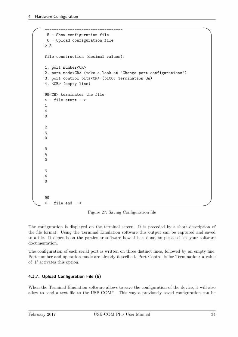
1. port number<CR>2. port mode<CR> (take a look at "Change port configurations")3. port control bits<CR> (bit0: Termination On)4. <CR> (empty line)
99<CR> terminates the file<-- file start -->140
240
340
440
99<-- file end -->
Figure 27: Saving Configuration file
The configuration is displayed on the terminal screen. It is preceded by a short description ofthe file format. Using the Terminal Emulation software this output can be captured and savedto a file. It depends on the particular software how this is done, so please check your softwaredocumentation.
The configuration of each serial port is written on three distinct lines, followed by an empty line.Port number and operation mode are already described. Port Control is for Termination: a valueof ’1’ activates this option.
4.3.7. Upload Configuration File (6)
When the Terminal Emulation software allows to save the configuration of the device, it will alsoallow to send a text file to the USB-COM+. This way a previously saved configuration can be
February 2017 USB-COM Plus User Manual 34

5 Technical Background on RS485
loaded to the USB-COM+. It can also be loaded to another device, for ease of configuring a seriesof USB-COM+. The last option ’6’ in the Main Menu (figure 22) provides this function.
5. Technical Background on RS485
This chapter will provide a little bit of theory about RS422 and RS485 data transmission. It isnecessary to have this basic knowledge, to avoid or find errors in data transmission. Failures incabling are responsible for the vast majority of transmission problems.
5.1. Transmission Technique
RS422 and RS485 use the same balanced transmission method. Signals are not transmitted byvoltage on a single wire, as RS232 does. Instead two wires are used; when one carries high voltage,the other one carries low voltage. The signal is defined by the difference in voltage between thosetwo wires. This hardens the transmission against noise. Usually twisted pairs are used, whichfurther reduces the sensitivity for noise.
Typical voltages are +4V as high, about +0.5V as low. These voltages are generated and definedagainst the GND signal of the transmitter. The minimum differential voltage is required as ±200mVby the specifications of RS422 and RS485. The receiver detects the polarity of the differentialvoltage, and thus gets a Zero (negative) or a One (positive) difference.
To do this detection the voltages on the receivers side have to be inside the bounds of the commonvoltage range defined as -7V through +12V, as measured against the local GND of the receiver.The specification of the common voltage range has been given to make the design of receiver circuitsmore simple and cost effective.
To make sure the signals meet the common voltage range, the GND of sender and receiver must beconnected somehow, otherwise the voltages are undefined and may have any value. To assure thecorrect range RS485 (RS422) usually requires an extra wire for GND8, which is often forgotten.The connection may also happen by protective ground, or by other means. If the connection ofGND is bad, it may be impossible to receive correct data.
5.2. Termination
When transmitted signals arrive at the end of a cable, they get reflected. They travel on the cableback and forth some more times, which is called ringing. This can cause false reading of transmitteddata. When the reflections travel on the cable several times, they are damped and do no longercause errors. This happens earlier if the cables are short.
For long cables Termination Resistors are required. These increase the damping of reflections. Thevalue of the resistor must match the impedance of the cable, typically 120Ω for twisted pair.
As a rule of thumb9, when the cables are longer than 1000000Bitrate (one million divided by the bit rate)
in meters, you should consider Termination Resistors.
8with an optional resistor9Assuming group speed of 100.000km/s, 10 travels to damp out, and 10% of bit time
February 2017 USB-COM Plus User Manual 35

5 Technical Background on RS485
5.3. Polarization
In RS485 the sender must activate the transmitter before sending data, and deactivate it when alldata is sent. At times when no devices send data all transmitters are inactive. As the result thedata lines are floating, and the differential voltage is undefined. It may happen the next data isnot correctly recognized, because the change from undefined to data signals is not detected.
To avoid such problems the data lines should be polarized by resistors. These insure the differentialvoltage to be above +200mV. Typically the positive line is pulled to +5V, while the negative line ispulled to GND. When Termination Resistors are applied, the voltage on these must be +200mV orabove. When the termination resistors are of the 120Ω types, the polarization resistors shall haveabout 750 to 1000Ω.
The Polarization Resistors must not be too small, because they add current to the signals, and atransmitter has to act against that. A typical transmitter provides up to 60 mA of current in highand low level.
5.4. 2-Wire Scheme
In many configurations a very simple cabling is required. RS485 allows for so called 2-wire cablingas shown below. Several devices are connected in parallel to the wires, which is called bus topology.Each device can either send own or receive foreign data at a given time, so it is operating inhalf-duplex mode.
Shown in figure 28 are three devices, RS485 specifies up to 32. The data lines are named as Data+and Data-, a positive differential voltage is the state for a transmitted One. The GND is alsoconnected between all devices as required, so the cabling is 3-wire in reality.
Figure 28: 2-wire cabling scheme
The resistors P1 and P2 are for polarization, T1 and T2 are for the termination function. Polari-zation of Data+ and Data- appears only once on this net, the termination is at the physical endsof the cable.
All devices appear the same on the cable, they have the same function. There is no Master orSlave defined by the hardware. Such functions are implemented by way of the data transmissionprotocol. Also RS485 addresses are defined by that protocol, as well as bus access.
February 2017 USB-COM Plus User Manual 36

5 Technical Background on RS485
5.5. 4-Wire Scheme
RS422 requires dedicated wire pairs for transmit and receive. The transmit wires are used to senddata to as many as 10 receivers, as stated in the specifications of RS422. Since the VScomproductsuse RS485 line driver technology, up to 32 receivers are possible.
While one pair is used to transmit, a second pair is available to receive data at the same time.When only two devices are connected, this is a possible replacement of classic RS232 connections(Point-to-Point).
In RS485 4-wire mode the transmit wires may be shared between dedicated stations. As an examplea second station can be a backup master for the network. Masters can send data and commandsto one station, while they receive information from another device.
Figure 29: 4-wire cabling scheme
Figure 29 displays the wire pairs Tx± and Rx± as named for Devices 1 and 2. There are moreslave devices, only two of them are shown. The slaves transmit on the Rx-lines, and receive on theTx-lines. To implement the Common Voltage Range as specified the GND line is also connected.
Masters on the network are identified because they transmit on the Tx-lines. The two Masters infigure 29 have to synchronize their use of the Tx-lines be extra means. E.g. Dev 2 can be a backupmaster, which is manually activated.
Also indicated in figure 29 are polarization resistors P1/P2 for Tx± and P3/P4 for Rx±, only onceper wire pair. Further Termination resistors T1/T2 for Tx± and T3/T4 for Rx± are added, one ateach end of the cable. To ensure the Common Voltage Range the GND is also connected at eachdevice, making this a 5-wire connection.
February 2017 USB-COM Plus User Manual 37

6 Connector Definitions
5.6. On USB-COM Plus Devices
As described above the USB-COM Plus provide an internal Termination resistor with a value of120Ω. This is activated by defining the configuration of the serial port.
The receiver circuits for RS422 and RS485 do not require resistors for BIAS function. Usingtermination resistors the differential voltage is 0Volt when all devices are inactive. The circuitsrecognize this voltage still as positive, so a logical One is detected. Therefore the USB-COM+ donot provide resistors for BIAS function.
6. Connector Definitions
All the VScom USB-COM Plus devices provide the today standard DSub9male connector for thesignals of the serial ports. An adapter to Terminal block for RS422 and RS485 signals is availableas an add-on (see 6.2).
The signal assignment for RS232 on DB910 male connectors is defined by the term “RS232” already.Below is the signal definition for the connectors used by the USB-COM Plus.
6.1. DB9 male
Usually this type of connector is used by customers. “4w” denotes the Full-Duplex mode, usuallynamed “4-wire”. Similarly “2w” denotes the Half-Duplex modes.
Pin RS232 RS422 RS485 “4w” RS485 “2w”1 DCD Tx− Tx− Data−2 RxD Tx+ Tx+ Data+3 TxD Rx+ Rx+4 DTR Rx− Rx−5 GND GND GND GND6 DSR7 RTS8 CTS9 RI
Table 11: DB9 male ConnectorFigure 30: DB9 male Connector
10Technically correct is DE9
February 2017 USB-COM Plus User Manual 38

6 Connector Definitions
6.2. Terminal Block Adapter
Figure 31: Terminal Block
When using RS422 and RS485 as transmission mode, sometimes thecommunication cables do not use a connector. Instead the wires aredirectly mounted into a clamp. To provide this options an adapterfrom the DB9 male connector to Terminal Block is available. Thisconnects the pins 1 through 5 to a clamp (Signals Tx- to GND).
6.3. Adapter RJ45
Figure 32: DB9-male to RJ45
This adapter enables to use standard Cat5 cables for transmissionin RS422 and RS485 modes. The signal assigment is chosen in away the differential signal pairs for Tx+/- and Rx+/- (Data+/-)use a twisted pair in the cable. Plug the DB9 female side intothe serial connector on USB-COM Plus, and use a Cat5 cable ofconvenient length for the transmission.
In principle this is also possible with RS232 mode. Hover the limitation of transmission length stillapplies, and a Cat5 cable does not provide for better signal quality in this mode.
Pin DB9 RS232 RS422 RS485 “4w” RS485 “2w” Pin RJ451 DCD Tx− Tx− Data− 82 RxD Tx+ Tx+ Data+ 73 TxD Rx+ Rx+ 34 DTR Rx− Rx− 65 GND GND GND GND 56 DSR 47 RTS 28 CTS 19 RI
Table 12: DB9 to RJ45
The adapter with reverse function converts signals from standard Cat5 cables back to the usualDB9 format. When used in pairs such transmission over Cat5 cable is like a straight cable with afemale connector at the first end and a male connector at the final end. This is a possible use inRS232 mode.
Figure 33: RJ45 to DB9-male
However the better use is for transmission in modes of RS422 orRS485. The differential signals for Tx+/- (Data+/-) and Rx+/-use twisted pairs in the Cat5 cable. It is possible to have a goodconnection with several hundred of meters in length, therefore theisolated serial ports are recommended for transmission over suchlong distances.
February 2017 USB-COM Plus User Manual 39

A History
A. History
October 2015 Release of Products and Manual
May 2016 Update with USB-16COM Plus option and Windows DriverAdd USB-COM Plus Configurator ApplicationAdd USB-COM Plus Mini device
February 2017 Add Connection AdaptersCurrent driver is version 2.12.24Warning for Wall Mount Kit (long screws not allowed)
February 2017 USB-COM Plus User Manual 40