Embed Size (px)
Citation preview

1
User Manual of Web Client

2
Index
Chapter 1 Software Installation......................................................................................................... 3
Chapter 2 Begin to Use...................................................................................................................... 5
2.1 Login and Exit ...................................................................................................................... 5
2.2 Preview Interface Instruction .............................................................................................. 6
2.3 Preview Image ..................................................................................................................... 7
Chapter 3 Playback ............................................................................................................................ 8
Chapter 4 Remote Configure ............................................................................................................. 9
4.1 Sever Parameter .................................................................................................................. 9
4.2 Channel Parameters .......................................................................................................... 10
4.3 Network Configuration ...................................................................................................... 14
4.4 Serial Parameters Configuration ....................................................................................... 16
4.5 Alarm Parameters Configuration ....................................................................................... 17
4.6 User Configuration ............................................................................................................ 19
4.7 Others ................................................................................................................................ 20
Chapter 5 Log .................................................................................................................................. 20

3
Chapter 1 Software Installation
This web client is embedded in DVR, when you use web browser to get access to DVR, it will be
downloaded automatically.
Please decrease the internet security level to make sure that the ActiveX could be downloaded
successfully. Open IE browser and select as following steps: ToolsInternet
optionssecurityinternetcustom level. As shown in fig 1.1. In the setting list you should
enable all the options about ActiveX control.
Fig 1.1
Input the IP address or domain name of DVR and press enter, the interface like fig 1.2 will pop
up. If you can see the interface, the ActiveX has been downloaded successfully.

4
Fig 1.2

5
Chapter 2 Begin to Use
2.1 Login and Exit
Input username and password correctly to get access to the web client. As shown in fig 2.1.
Fig 2.1
After getting access to the web client, you can click logout then click OK in pop-up dialog box
to exit. As shown in fig 2.2.
Fig 2.2
6
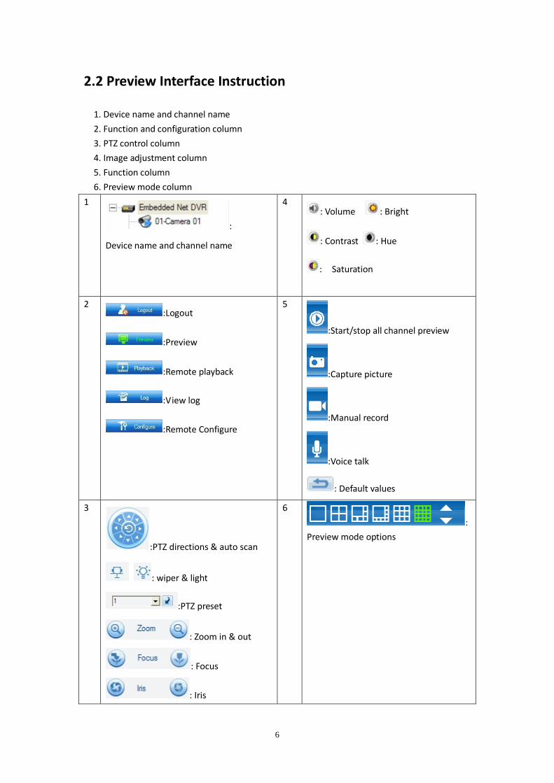
2.2 Preview Interface Instruction
1. Device name and channel name
2. Function and configuration column
3. PTZ control column
4. Image adjustment column
5. Function column
6. Preview mode column
1
:
Device name and channel name
4 : Volume : Bright
: Contrast : Hue
: Saturation
2 :Logout
:Preview
:Remote playback
:View log
:Remote Configure
5
:Start/stop all channel preview
:Capture picture
:Manual record
:Voice talk
: Default values
3
:PTZ directions & auto scan
: wiper & light
:PTZ preset
: Zoom in & out
: Focus
: Iris
6
:
Preview mode options

7
2.3 Preview Image
Step 1 Select a preview mode.
Step 2 Select one split window and double click channel name to start to preview.
Step 3 Right click right key and select main stream and sub stream for previewing, as fig 2.3
shown below:
Fig 2.3
8
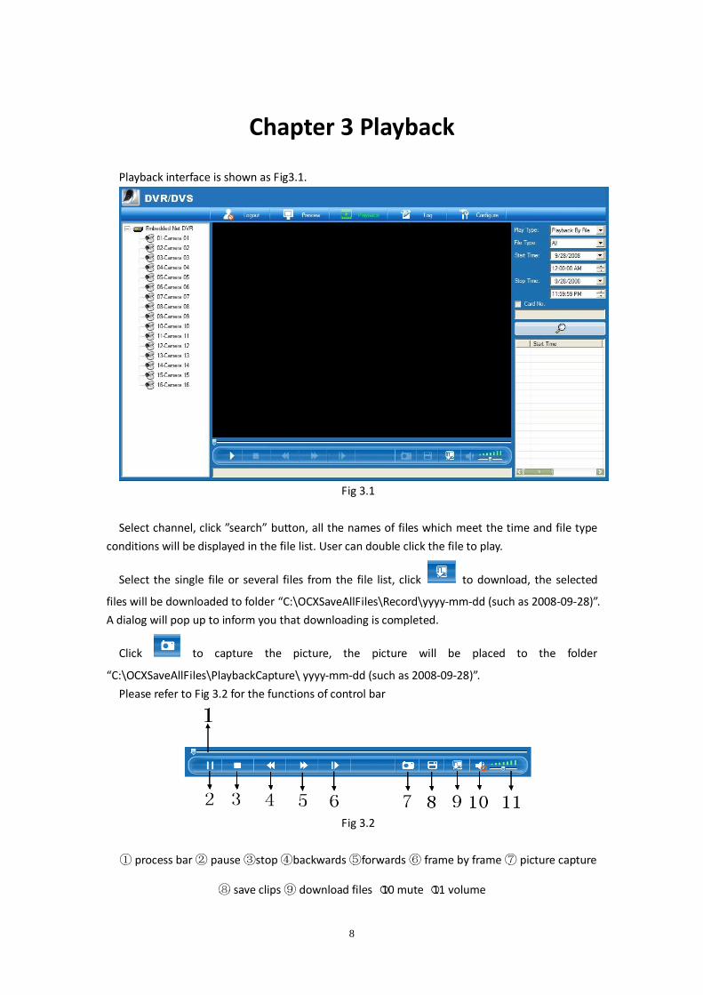
Chapter 3 Playback
Playback interface is shown as Fig3.1.
Fig 3.1
Select channel, click ”search” button, all the names of files which meet the time and file type
conditions will be displayed in the file list. User can double click the file to play.
Select the single file or several files from the file list, click to download, the selected
files will be downloaded to folder “C:\OCXSaveAllFiles\Record\yyyy-mm-dd (such as 2008-09-28)”.
A dialog will pop up to inform you that downloading is completed.
Click to capture the picture, the picture will be placed to the folder
“C:\OCXSaveAllFiles\PlaybackCapture\ yyyy-mm-dd (such as 2008-09-28)”.
Please refer to Fig 3.2 for the functions of control bar
Fig 3.2
① process bar ② pause ③stop ④backwards ⑤forwards ⑥ frame by frame ⑦ picture capture
⑧ save clips ⑨ download files ○10 mute ○11 volume

9
Chapter 4 Remote Configure
Click configure button to enter the Remote parameters configure interface.
4.1 Sever Parameter
Fig 4.1
There are two parts: server configuration information & server version information.
Server configuration information:
Server name: no more than 32 letters, 16 characters at most.
Device ID: the largest NO. is 255.
Cycle record: if you want to overwrite after the HDD is full, just select “YES”, if you want to stop
record after the HDD is full, just select “NO”.
Enable scalar.
The channel number, HDD number, alarm input number, alarm output number, server type,
server serial can’t be modified.
IP address, port and subnet mask: server static IP, port and subnet mask are corresponding.
The default port is 8000.

10
NIC type: here are some options such as 10M/100M Auto and so on.
Multicast IP: when you use the multicast, you should input a D-class IP. Range 224.0.0.0 ~
239.255.255.255.
Gateway: if client software needs go through the gateway to connect the server, you should
input a gateway.
NAS host IP and NAS directory: if using network store server, you can just input the NAS IP and
the directory.
Remote host IP and port: IP and port of the PC that used for receiving alarm information.
Http port: applied when you use the IE to access to the server.
The MAC address can’t be modified.
Server version information:
Firmware version, Hardware version, Encode version and Front panel version can’t be
modified.
After the configuration is finished, click “confirm”. If needs to reboot, just click “Reboot”
button.
4.2 Channel Parameters
Fig 4.2
Select channel: select one channel of the server.

11
Channel name: it can be modified, 32 letters or 16 characters at most.
Type: Generally, main stream is used for recording, sub stream is used for network
transmission.
Frame type: BBP and P can be selected.
I Frame: can be modified.
Image quality: 6 options (only effective for variable bit rate type).
Frame rate: Full (PAL: 25FPS NTSC: 30FPS), 20, 16, 12, 10, 8, 6, 4, 2, 1, 1/2, 1/4, 1/8, 1/16. (Notice:
15, 18 and 22 are special options which only some special servers have.)
Stream type: if you select “video & audio” in the channel properties interface, then both the
video and audio can be recorded, or else you can select “video” only.
Max bit rate: You can select 32kbps, 48kbps, 64kbps, 80kbps, 96kbps, 128kbps, 160kbps,
192kbps, 224kbps, 256kbps, 320kbps, 384kbps, 448kbps, 512kbps, 640kbps, 768kbps, 896kbps,
1Mbps, 1.25Mbps, 1.5Mbps, 1.75Mbps, 2Mbps and user-defined.
Resolution: Default is CIF; other options are QCIF, 2CIF, DCIF and 4CIF. Only QCIF and CIF can be
select as it is sub stream.
Bit rate type: Variable and Fixed can be selected.
Recording plan: Enable “schedule” option, you can setup the record time, prerecord time, and
post record time. Click “set” button to enter recording schedule setup dialog. Select record mode,
if select all day record, only record type can be setup. If finish the setup, click “confirm” button to
return. Click “cancel” to return if you do not want to save the configuration.
Pre record time: Recording time options before alarm happened. The options are including no
prerecord, 5s, 10s, 15s, 20s, 25s, 30s, maximum.
Post record time: Recording time options after alarm stopped. The options are including 5s,
10s, 30s, 1min, 2min, 5min, 10min.
Setup motion detection, video signal loss, view tamping alarm and privacy mask:
Select an option and setup the corresponding area, schedule and linkage type.
Click “area setup” to enter area setup interface. Shown as fig 4.3

12
Fig 4.3
Enable set area, press “ctrl” and drag mouse with left key.
Enable “show areas” to display the area. Press OK to confirm.
Click “schedule” to enter schedule setup interface. As shown in fig 4.4.
Fig 4.4

13
Click “linkage” to enter alarm linkage configure interface. As shown in fig 4.5.
Fig4.5
Setup OSD properties: you can select whether display OSD, display position, whether display
week, OSD properties (opaque & steady, opaque & flashing, transparent & steady, transparent &
flashing, no display). OSD type (i.e. date & time display types).
Setup the channel name properties: you can select whether display channel name and the
display position).
Overlay text: you can overlay text on the channel, 4 line at most, 44 characters at most for
every line.
After setting the parameters, click “confirm”. If the server needs to reboot, just click “reboot”
button.
(Notice: the information and channel name in all time record, motion detection record, video
loss, privacy mask, and view tampering can’t be copied to the other channels)

14
4.3 Network Configuration
In the remote configuration, you can click network configuration button to set network
parameter. As shown in Fig.4.6.
Fig4.6
1. NFS configuration Info: This function can be used with NAS in server configuration, DVR
will regard network HDD as local HDD. DVR will send and save the real time image to
the appointed network HDD.
Disk NO.: Network HDD No. (Max supports 8 HDDs).
Server IP: The IP of the network storage server.
Directory: The directory for accessing the network storage server.
2. IP-Server configuration info: Applicable to the device that not only uses PPPoE dial-up
but also resolves the private domain via IP server.
IP-Server IP: resolve the server’s IP address, namely the address of server which runs
the IP server software.

15
Enable PPPoE: you can select whether to enable the PPPoE.
PPPoE user name, password, verify password: input the PPPoE user name and
password which provided by ISP.
3. DNS server: IP address of resolving server.
4. E-mail configuration: This function enables image capture and sending
emails to designated e-mail address (max 2 e-mail addresses at the same time)
when abnormity occurred. As shown in fig.4.7.
Fig.4.7
Sender Name: Name appears in Email
Sender Address: Sender Email address
User Name: Email account user name
Authentication: If your Email server asks for a user name and password when sending Email,
you need to tick this check box
Password: Email account password & Verify Password.
Mail receiver name: The name appears in Email
Mail receiver address: Receiver Email address
Attachment JPEG: Sending the Email with JPEG picture capture when abnormity occurred.
Email server: SMPT supported Email sending server
JPEG Capture Interval.
5. DDNS configuration info: Currently supports two protocols provided by DDNS service
supplier.
Server type: server address that provided by carrier like www.dyndns.com or
www.peanuthull.com.
Enable DDNS.

16
User name and password: The user name and password of your DDNS account get from
DDNS service supplier.
Host name: The domain name register by yourself on the web site of dyndns or
peanuthull.
Server address: The DDNS server provided by DDNS service supplier
Server Port: Provided by the supplier.
6. NTP configuration info: NTP is used for synchronizing time with time
server, time server is provided by NTP service provider: time.windows.com which
is a famous time server provided by Microsoft.
Enable NTP.
NTP Host: NTP server name.
Check time: time interval for checking time automatically.
Time zone: the gap between the system time and Greenwich Mean Time.
4.4 Serial Parameters Configuration
Select “COM configuration” in the remote configuration, show as fig 4.6.
In this interface, you can setup the parameters of 232 and 485.
After the configuration, click “confirm”. If needs to reboot the server, just click “reboot”
button.
Fig 4.6

17
4.5 Alarm Parameters Configuration
Select “alarm configuration” in the remote setup interface. Show as Fig 4.7.
You can remote setup DVR sensor alarm parameters and the exception parameters.
Fig 4.7
Alarm input response policy:
Select “Method” option, click “alarm time” button to enter alarm response policy setup
interface shown as Fig 4.8.

18
Fig 4.8
Click “Linkage” button to enter alarm linkage type configuration interface, shown as fig 4.9.
Fig 4.9
Alarm output policy setup:

19
Click “alarm time” to setup alarm output schedule.
Exception Config:
The Exception configuration includes HDD full, HDD error, network broken, illegal access, video
standard not matched, etc, also you can setup exceptions response policy.
4.6 User Configuration
In this interface you can remote setup DVR users, including username, password, user rights,
etc.
Check the user right when you select the user.
If the user exists, just right click the user and click “modify” in the popup menu. Select
“cancel” to return.
After finish, click “OK”, “Save Para.” button. Please reboot DVR to make the new parameter
become effective. Shown as fig 4.10
Fig 4.10

20
4.7 Others
User can remote upgrade server or format Hard Disk in this interface. Shown as fig 4.11.
Select “Remote Upgrade”, single click “Explore”, select upgrade file. Click “Upgrade” to begin
upgrade process. After completing upgrade, status tray will show “Status: Server Upgrade finish”.
Select “Format Hard Disk”, select the disk you want to operate on (all or only one disk of them),
single click “Format”, the system will indicate that Format is under process. After the process, it
will indicate “Format Hard Disk Successful”.
NOTE: After the formation of hard disk, a reset of the equipment is indispensable. No other
operations are allowed during the formation process.
Fig 4.11
Chapter 5 Log
Select search type, start time and stop time then click to
search. Shown as fig 5.1

21
Fig 5.1