Embed Size (px)
Citation preview
iVMS-5200 Professional Control Client
User Manual UD01664B
User Manual of iVMS-5200 Professional Control Client
1
User Manual
COPYRIGHT © 2016 Hangzhou Hikvision Digital Technology Co., Ltd.
ALL RIGHTS RESERVED.
Any and all information, including, among others, wordings, pictures, graphs are the properties of
Hangzhou Hikvision Digital Technology Co., Ltd. or its subsidiaries (hereinafter referred to be
“Hikvision”). This user manual (hereinafter referred to be “the Manual”) cannot be reproduced,
changed, translated, or distributed, partially or wholly, by any means, without the prior written
permission of Hikvision. Unless otherwise stipulated, Hikvision does not make any warranties,
guarantees or representations, express or implied, regarding to the Manual.
About this Manual
This Manual is applicable to iVMS-5200 Professional Control Client.
The Manual includes instructions for using and managing the product. Pictures, charts, images and all
other information hereinafter are for description and explanation only. The information contained in
the Manual is subject to change, without notice, due to firmware updates or other reasons. Please
find the latest version in the company website (http://overseas.hikvision.com/en/).
Please use this user manual under the guidance of professionals.
Trademarks Acknowledgement
and other Hikvision’s trademarks and logos are the properties of Hikvision in
various jurisdictions. Other trademarks and logos mentioned below are the properties of their
respective owners.
Legal Disclaimer
TO THE MAXIMUM EXTENT PERMITTED BY APPLICABLE LAW, THE PRODUCT DESCRIBED, WITH ITS
HARDWARE, SOFTWARE AND FIRMWARE, IS PROVIDED “AS IS”, WITH ALL FAULTS AND ERRORS, AND
HIKVISION MAKES NO WARRANTIES, EXPRESS OR IMPLIED, INCLUDING WITHOUT LIMITATION,
MERCHANTABILITY, SATISFACTORY QUALITY, FITNESS FOR A PARTICULAR PURPOSE, AND
NON-INFRINGEMENT OF THIRD PARTY. IN NO EVENT WILL HIKVISION, ITS DIRECTORS, OFFICERS,
EMPLOYEES, OR AGENTS BE LIABLE TO YOU FOR ANY SPECIAL, CONSEQUENTIAL, INCIDENTAL, OR
INDIRECT DAMAGES, INCLUDING, AMONG OTHERS, DAMAGES FOR LOSS OF BUSINESS PROFITS,
User Manual of iVMS-5200 Professional Control Client
2
BUSINESS INTERRUPTION, OR LOSS OF DATA OR DOCUMENTATION, IN CONNECTION WITH THE USE
OF THIS PRODUCT, EVEN IF HIKVISION HAS BEEN ADVISED OF THE POSSIBILITY OF SUCH DAMAGES.
REGARDING TO THE PRODUCT WITH INTERNET ACCESS, THE USE OF PRODUCT SHALL BE WHOLLY AT
YOUR OWN RISKS. HIKVISION SHALL NOT TAKE ANY RESPONSIBILITIES FOR ABNORMAL OPERATION,
PRIVACY LEAKAGE OR OTHER DAMAGES RESULTING FROM CYBER ATTACK, HACKER ATTACK, VIRUS
INSPECTION, OR OTHER INTERNET SECURITY RISKS; HOWEVER, HIKVISION WILL PROVIDE TIMELY
TECHNICAL SUPPORT IF REQUIRED.
SURVEILLANCE LAWS VARY BY JURISDICTION. PLEASE CHECK ALL RELEVANT LAWS IN YOUR
JURISDICTION BEFORE USING THIS PRODUCT IN ORDER TO ENSURE THAT YOUR USE CONFORMS THE
APPLICABLE LAW. HIKVISION SHALL NOT BE LIABLE IN THE EVENT THAT THIS PRODUCT IS USED WITH
ILLEGITIMATE PURPOSES.
IN THE EVENT OF ANY CONFLICTS BETWEEN THIS MANUAL AND THE APPLICABLE LAW, THE LATER
PREVAILS.
User Manual of iVMS-5200 Professional Control Client
3
Contents Chapter 1 Overview.......................................................................................................................... 5
1.1 Description ...................................................................................................................... 5
1.2 Running Environment ...................................................................................................... 5
1.3 Function Modules ............................................................................................................ 5
Chapter 2 Login ................................................................................................................................ 8
Chapter 3 Live View ........................................................................................................................ 11
3.1 Starting and Stopping the Live View .............................................................................. 13
3.2 Auto-switch in Live View ................................................................................................ 14
3.3 PTZ Control in Live View ................................................................................................ 16
3.4 Manual Recording and Capture ..................................................................................... 17
3.5 Instant Playback ............................................................................................................. 21
3.6 Custom Window Division............................................................................................... 22
3.7 Live View in Fisheye Mode ............................................................................................ 23
3.8 Live Viewing the Video from Mobile Terminal............................................................... 25
3.9 Other Functions in Live View ......................................................................................... 27
Chapter 4 Remote Playback ........................................................................................................... 28
4.1 Normal Playback ............................................................................................................ 28
4.2 Event Playback ............................................................................................................... 35
4.3 POS Playback ................................................................................................................. 36
4.4 Synchronous Playback ................................................................................................... 37
4.5 VCA Playback ................................................................................................................. 37
4.6 Fisheye Playback ............................................................................................................ 38
Chapter 5 E-map Management ...................................................................................................... 40
5.1 Adding an E-map ........................................................................................................... 40
5.2 Hot Spot Function .......................................................................................................... 42
5.2.1 Adding the Hot Spot .............................................................................................. 42
5.2.2 Editing the Hot Spots ............................................................................................. 45
5.2.3 Previewing the Hot Spots ...................................................................................... 46
5.3 Hot Region Function ...................................................................................................... 49
5.3.1 Adding the Hot Regions ......................................................................................... 49
5.3.2 Editing the Hot Regions ......................................................................................... 50
5.3.3 Previewing the Hot Regions .................................................................................. 51
5.4 Preset Function .............................................................................................................. 52
Chapter 6 Business Intelligence ..................................................................................................... 53
Chapter 7 POS Live View ................................................................................................................ 57
7.1 Starting and Stopping the POS Live View ...................................................................... 59
Chapter 8 POS Search ..................................................................................................................... 61
Chapter 9 People Counting Statistics ............................................................................................. 65
Chapter 10 Heat Map ....................................................................................................................... 67
Chapter 11 Alarm Center ................................................................................................................. 69
11.1 Alarm Information of Resources .................................................................................... 70
11.2 Searching Event/Alarm Logs .......................................................................................... 72

User Manual of iVMS-5200 Professional Control Client
4
11.3 Alarm Information of iVMS-5200 Pro ............................................................................ 73
Chapter 12 Download Center ........................................................................................................... 74
Chapter 13 Log Management ........................................................................................................... 77
Chapter 14 Local Configuration ........................................................................................................ 80
14.1 General Settings ............................................................................................................ 80
14.2 File Saving Path Settings ................................................................................................ 82
14.3 Keyboard and Joystick Shortcuts Settings ..................................................................... 83
14.4 Alarm Sound Settings .................................................................................................... 84
Chapter 15 Status Detection ............................................................................................................ 86
15.1 Physical View ................................................................................................................. 86
15.2 Logical View ................................................................................................................... 87
User Manual of iVMS-5200 Professional Control Client
5
Chapter 1 Overview
1.1 Description
As one of the key components of the iVMS-5200 Professional (hereafter simplified as iVMS-5200 Pro),
iVMS-5200 Pro Control Client provides multiple operating functionalities, including real-time live view,
PTZ control, video playback and download, alarm receiving, log query, and so on.
This user manual describes the function, configuration and operation steps of iVMS-5200 Pro Control
Client. To ensure the proper usage and stability of the client, please refer to the contents below and
read the manual carefully before operation.
1.2 Running Environment
Operating System: Microsoft Windows 7/Windows 8/Windows 8.1/Windows Server 2008
R2/Windows Server 2012 (32/64-bit), Windows 10 (64-bit)
CPU: Intel Core i3-530 and above
Memory: 4GB and above
Video Card: Geforce GTX 240 and above
Note: For high stability and good performance, these above system requirements must be met.
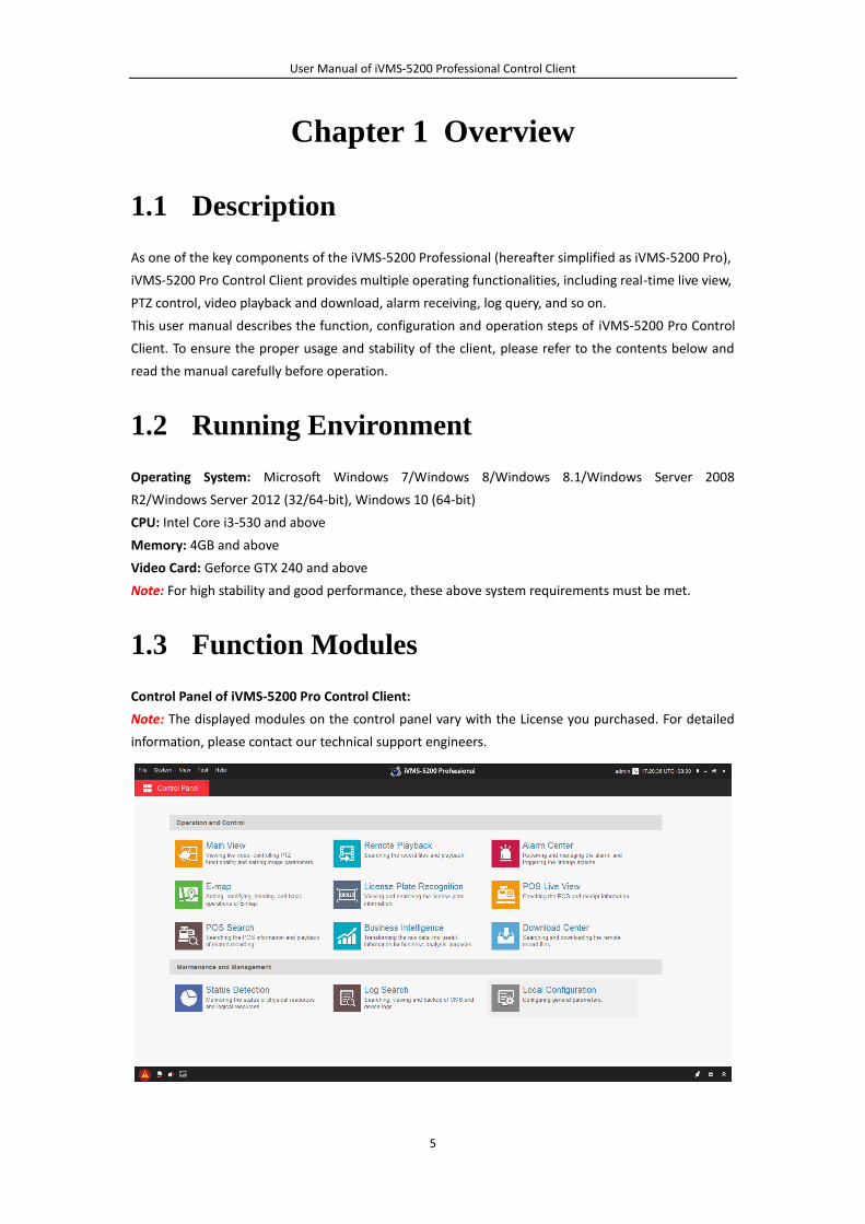
1.3 Function Modules
Control Panel of iVMS-5200 Pro Control Client:
Note: The displayed modules on the control panel vary with the License you purchased. For detailed
information, please contact our technical support engineers.
User Manual of iVMS-5200 Professional Control Client
6
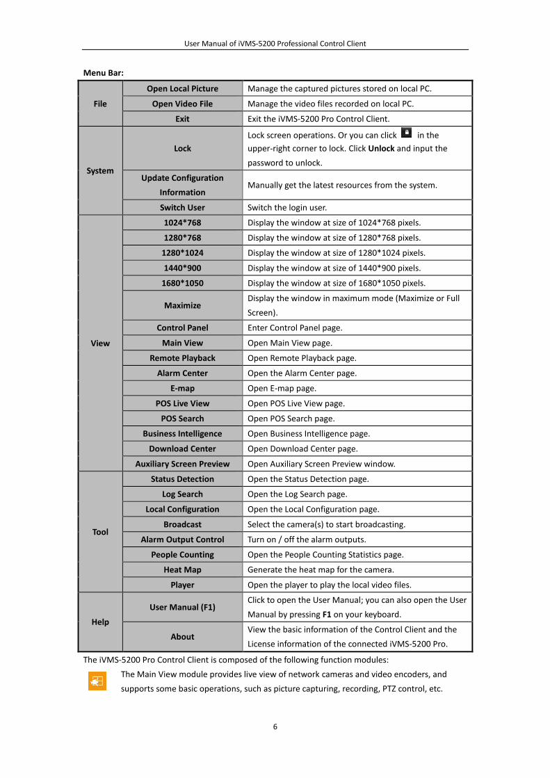
Menu Bar:
File
Open Local Picture Manage the captured pictures stored on local PC.
Open Video File Manage the video files recorded on local PC.
Exit Exit the iVMS-5200 Pro Control Client.
System
Lock
Lock screen operations. Or you can click in the
upper-right corner to lock. Click Unlock and input the
password to unlock.
Update Configuration
Information Manually get the latest resources from the system.
Switch User Switch the login user.
View
1024*768 Display the window at size of 1024*768 pixels.
1280*768 Display the window at size of 1280*768 pixels.
1280*1024 Display the window at size of 1280*1024 pixels.
1440*900 Display the window at size of 1440*900 pixels.
1680*1050 Display the window at size of 1680*1050 pixels.
Maximize Display the window in maximum mode (Maximize or Full
Screen).
Control Panel Enter Control Panel page.
Main View Open Main View page.
Remote Playback Open Remote Playback page.
Alarm Center Open the Alarm Center page.
E-map Open E-map page.
POS Live View Open POS Live View page.
POS Search Open POS Search page.
Business Intelligence Open Business Intelligence page.
Download Center Open Download Center page.
Auxiliary Screen Preview Open Auxiliary Screen Preview window.
Tool
Status Detection Open the Status Detection page.
Log Search Open the Log Search page.
Local Configuration Open the Local Configuration page.
Broadcast Select the camera(s) to start broadcasting.
Alarm Output Control Turn on / off the alarm outputs.
People Counting Open the People Counting Statistics page.
Heat Map Generate the heat map for the camera.
Player Open the player to play the local video files.
Help
User Manual (F1) Click to open the User Manual; you can also open the User
Manual by pressing F1 on your keyboard.
About View the basic information of the Control Client and the
License information of the connected iVMS-5200 Pro.
The iVMS-5200 Pro Control Client is composed of the following function modules:
The Main View module provides live view of network cameras and video encoders, and
supports some basic operations, such as picture capturing, recording, PTZ control, etc.
User Manual of iVMS-5200 Professional Control Client
7
The Remote Playback module provides the search, playback, export of record files.
The Alarm Center module provides the displaying and management of alarm information
received by the Control Client.
The E-map module provides the displaying and management of E-maps, alarm inputs, hot
regions and hot spots.
The POS Live View module provides the POS and receipt information.
The POS Search module provides POS information and playback of related recording.
The Business Intelligence module provides intelligent business analysis.
The Download Center module provides the search and downloading of the remote record
files.
The Status Detection module provides the function of displaying the status of the server,
connected devices and the cameras of the devices.
The Log Search module provides the query and backup of CMS and device log files.
The Local Configuration module provides the configuration of general parameters, file
saving paths, alarm sounds and other settings for the Control Client.
If the resources of the iVMS-5200 Pro have changed (e.g., more devices are added to the system), a
dialog will pop up to ask you to synchronize with the system to get the latest resources.
The function modules are easily accessed by clicking the navigation buttons on the control panel or by
selecting the function module from the View or Tool menu.
You can check the information, including current user, network usage, CPU usage, RAM usage and
time, in the upper-right corner of the main page.
User Manual of iVMS-5200 Professional Control Client
8
Chapter 2 Login
When opening iVMS-5200 Pro Control Client, you can login with the user name and password of
iVMS-5200 Pro.
Two kinds of user (normal user and domain user) are supported for accessing the iVMS-5200 Pro.
Please refer to the User Manual of iVMS-5200 Pro Web Client for the detailed introduction.
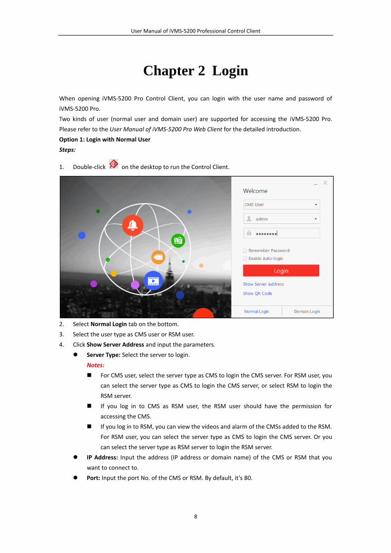
Option 1: Login with Normal User
Steps:
1. Double-click on the desktop to run the Control Client.
2. Select Normal Login tab on the bottom.
3. Select the user type as CMS user or RSM user.
4. Click Show Server Address and input the parameters.
Server Type: Select the server to login.
Notes:
For CMS user, select the server type as CMS to login the CMS server. For RSM user, you
can select the server type as CMS to login the CMS server, or select RSM to login the
RSM server.
If you log in to CMS as RSM user, the RSM user should have the permission for
accessing the CMS.
If you log in to RSM, you can view the videos and alarm of the CMSs added to the RSM.
For RSM user, you can select the server type as CMS to login the CMS server. Or you
can select the server type as RSM server to login the RSM server.
IP Address: Input the address (IP address or domain name) of the CMS or RSM that you
want to connect to.
Port: Input the port No. of the CMS or RSM. By default, it’s 80.
User Manual of iVMS-5200 Professional Control Client
9
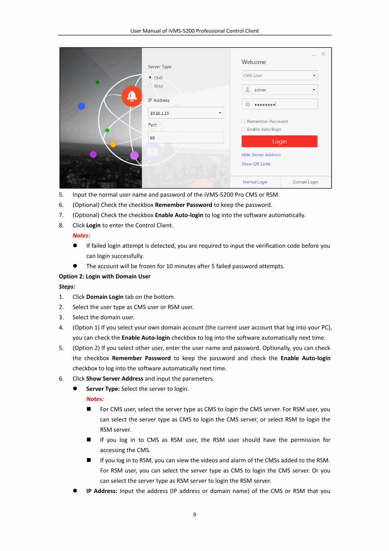
5. Input the normal user name and password of the iVMS-5200 Pro CMS or RSM.
6. (Optional) Check the checkbox Remember Password to keep the password.
7. (Optional) Check the checkbox Enable Auto-login to log into the software automatically.
8. Click Login to enter the Control Client.
Notes:
If failed login attempt is detected, you are required to input the verification code before you
can login successfully.
The account will be frozen for 10 minutes after 5 failed password attempts.
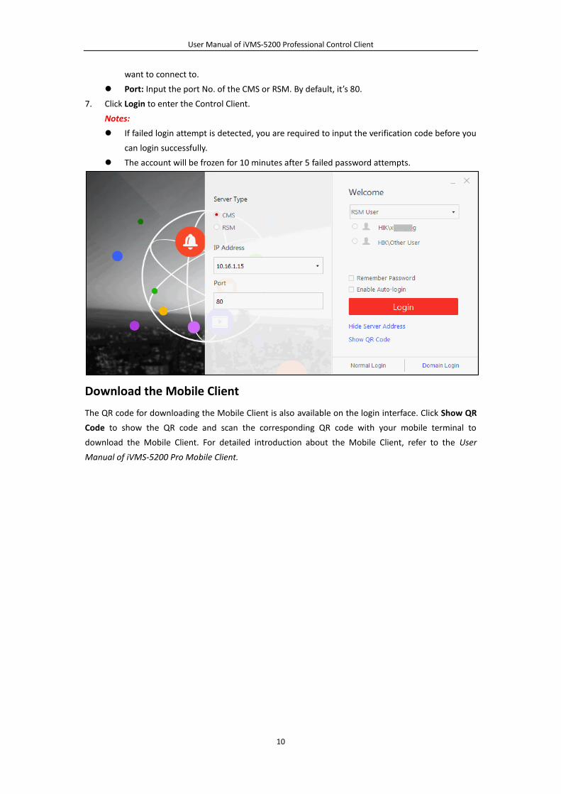
Option 2: Login with Domain User
Steps:
1. Click Domain Login tab on the bottom.
2. Select the user type as CMS user or RSM user.
3. Select the domain user.
4. (Option 1) If you select your own domain account (the current user account that log into your PC),
you can check the Enable Auto-login checkbox to log into the software automatically next time.
5. (Option 2) If you select other user, enter the user name and password. Optionally, you can check
the checkbox Remember Password to keep the password and check the Enable Auto-login
checkbox to log into the software automatically next time.
6. Click Show Server Address and input the parameters.
Server Type: Select the server to login.
Notes:
For CMS user, select the server type as CMS to login the CMS server. For RSM user, you
can select the server type as CMS to login the CMS server, or select RSM to login the
RSM server.
If you log in to CMS as RSM user, the RSM user should have the permission for
accessing the CMS.
If you log in to RSM, you can view the videos and alarm of the CMSs added to the RSM.
For RSM user, you can select the server type as CMS to login the CMS server. Or you
can select the server type as RSM server to login the RSM server.
IP Address: Input the address (IP address or domain name) of the CMS or RSM that you
User Manual of iVMS-5200 Professional Control Client
10
want to connect to.
Port: Input the port No. of the CMS or RSM. By default, it’s 80.
7. Click Login to enter the Control Client.
Notes:
If failed login attempt is detected, you are required to input the verification code before you
can login successfully.
The account will be frozen for 10 minutes after 5 failed password attempts.
Download the Mobile Client
The QR code for downloading the Mobile Client is also available on the login interface. Click Show QR
Code to show the QR code and scan the corresponding QR code with your mobile terminal to
download the Mobile Client. For detailed introduction about the Mobile Client, refer to the User
Manual of iVMS-5200 Pro Mobile Client.
User Manual of iVMS-5200 Professional Control Client
11
Chapter 3 Live View
Purpose:
For the surveillance task, you can view the live video of the added network cameras and encoding
devices on the Main View page. And some other basic operations are supported, including picture
capturing, manual recording, PTZ control, and so on.
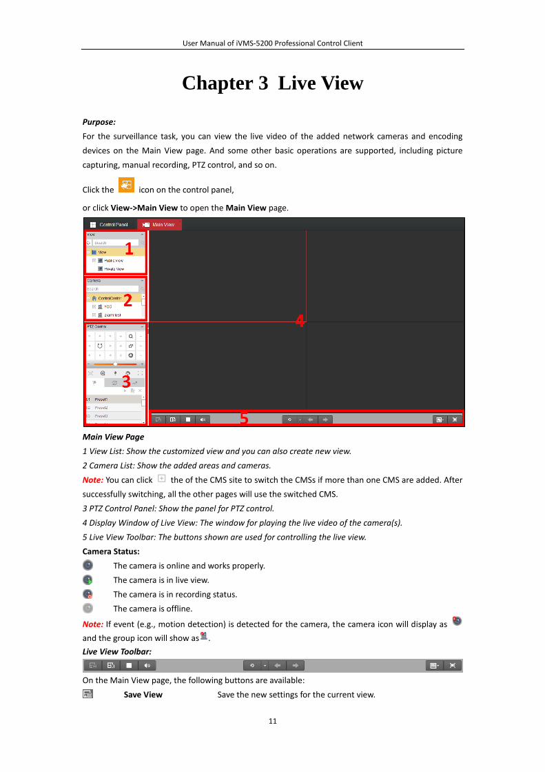
Click the icon on the control panel,
or click View->Main View to open the Main View page.
Main View Page
1 View List: Show the customized view and you can also create new view.
2 Camera List: Show the added areas and cameras.
Note: You can click the of the CMS site to switch the CMSs if more than one CMS are added. After
successfully switching, all the other pages will use the switched CMS.
3 PTZ Control Panel: Show the panel for PTZ control.
4 Display Window of Live View: The window for playing the live video of the camera(s).
5 Live View Toolbar: The buttons shown are used for controlling the live view.
Camera Status:
The camera is online and works properly.
The camera is in live view.
The camera is in recording status.
The camera is offline.
Note: If event (e.g., motion detection) is detected for the camera, the camera icon will display as
and the group icon will show as .
Live View Toolbar:
On the Main View page, the following buttons are available:
Save View Save the new settings for the current view.
User Manual of iVMS-5200 Professional Control Client
12
Save View As Save the current view as another new view.
Stop Live View Stop the live view of all cameras.
Mute/Audio On Turn off/on the audio in live view
Resume/Pause
Auto-switch Click to resume/pause the auto-switch in live view.
Show/Hide the Menu
Show/Hide the configuration menu of auto-switch. Click again
to hide. The switching interval cannot be edited during
auto-switch.
Previous Go for live view of the previous camera in auto-switch mode.
Next Go for live view of the next camera in auto-switch mode.
Screen Layout Set the screen layout.
Full Screen Display the live view in full-screen mode. Press Esc key to exit.
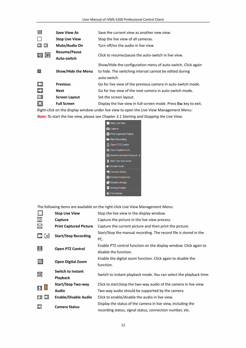
Right-click on the display window under live view to open the Live View Management Menu:
Note: To start the live view, please see Chapter 3.1 Starting and Stopping the Live View.
The following items are available on the right-click Live View Management Menu:
Stop Live View Stop the live view in the display window.
Capture Capture the picture in the live view process.
Print Captured Picture Capture the current picture and then print the picture.
Start/Stop Recording Start/Stop the manual recording. The record file is stored in the
PC.
Open PTZ Control Enable PTZ control function on the display window. Click again to
disable the function.
Open Digital Zoom Enable the digital zoom function. Click again to disable the
function.
Switch to Instant
Playback Switch to instant playback mode. You can select the playback time.
Start/Stop Two-way
Audio
Click to start/stop the two-way audio of the camera in live view.
Two-way audio should be supported by the camera.
Enable/Disable Audio Click to enable/disable the audio in live view.
Camera Status Display the status of the camera in live view, including the
recording status, signal status, connection number, etc.
User Manual of iVMS-5200 Professional Control Client
13
Fisheye Expansion Enter the fisheye expansion mode. For details, please refer to
Chapter 3.7 Live View in Fisheye Mode.
Enable Linkage
The linked speed dome of the fisheye camera can track the target
manually by clicking the target on the live view, or the track the
target automatically according to the configured rules.
Notes:
This icon is only available for the fisheye camera that
supports the speed dome linkage.
For configuring the speed dome linkage for the fisheye
camera, refer to the User Manual of iVMS-5200 Pro Web
Client.
Arming Control Open the arming control window of the camera in live view.
Full Screen Display the live view in full-screen mode. Press Esc key to exit.
3.1 Starting and Stopping the Live View
Starting Live View for One Camera
Steps:
1. Open the Main View page.
2. (Optional) Click and select the window division mode for live view.
3. Click-and-drag the camera to the display window,
or double-click the camera name after selecting the display window to start the live view.
Note: You can click-and-drag the video of the camera in live view to another display window if
needed.
Starting Live View for Area
Steps:
1. Open the Main View page.
2. Click-and-drag the area to the display window,
or double-click the area name to start the live view. You can also click-and-drag or double-click
the Control Center node to start the live view of all the added devices
Notes:
The display window number is self-adaptive to the camera number of the area.
If the number of the cameras is greater than that of the windows, the live view will be performed
in multiple windows. You can click or to view the live video.
Starting Live View in Custom View Mode
Purpose:
The view mode can be customized for the live view. You can select to create public view or private
view.
Public View: The customized public view will be saved to the iVMS-5200 Pro and the other users
can also get access to the view and the related live video.
User Manual of iVMS-5200 Professional Control Client
14
Private View: The customized private view will be saved to the iVMS-5200 Pro and other users
who have the corresponding permission can also get access to the view and the related live
video.
Steps:
1. Open the Main View page.
2. In the view panel, click the icon to activate the view adding dialog box.
3. Input the view name and select the view type according to actual needs.
4. Click Add. The new view is of 4-Screen mode by default.
5. (Optionally) Click the icon in live view toolbar and select the window division mode for the
new view and click to save the window division mode for the new view.
6. Click-and-drag the camera to the display window,
or double-click the camera name after selecting the display window to start the live view.
Note: The live view of the cameras that do not belong to the same CMS cannot be saved in the
same view.
7. Click the icon to save the new view. Optionally, you can click to save the current view
as another view.
After successfully setting the view, you can click the view to call it.
Move the mouse onto the custom view, the following icons are available:
Edit View Name Edit the name of the custom view.
Delete View Delete the custom view.
Instant Playback
Start the instant playback of the cameras related to the
view. Up to 16 cameras can be switch to instant playback at
the same time.
Stopping the Live View
Steps:
1. Select the display window.
2. Click the icon that appears in the upper-right corner when the mouse pointer is over the
display window, or click Stop Live View on the right-click menu to stop the live view of the display
window. You can also click the button in live view toolbar to stop all the live view.
3.2 Auto-switch in Live View
Camera Auto-switch
Purpose:
The video stream of the cameras from the same area will switch automatically in a selected display
window in camera auto-switch.
Steps:
1. Open the Main View page.
2. Select a display window for camera auto-switch.
3. Click the icon in the toolbar and select the switching interval.
4. Select an area and click the icon on the area node.

User Manual of iVMS-5200 Professional Control Client
15
5. You can click the icon / to pause/resume the camera auto-switch.
View Auto-switch
Purpose:
The custom views will switch automatically in view auto-switch. The custom views need to be added
before proceeding.
Steps:
1. Open the Main View page.
2. Click the icon in the toolbar and select the switching interval.
3. Click the icon on the View, Public View or Private View node.
Notes:
If you select View for auto-switch, all the customized views will switch automatically.
If you select Public or Private View, the customized public views or private views will switch
automatically.
If the number of the cameras is greater than that of the windows, the auto-switch will be
performed in multiple windows. You can click or to view the auto-switch.
4. You can click the icon / to pause/resume the multi-view auto-switch.
Area Auto-switch
Purpose:
The cameras of the area will switch automatically in area auto-switch.
Steps:
1. Open the Main View page.
2. Select a display window for area auto-switch.
3. Click the icon in the toolbar and select the switching interval.
4. Click the icon on the area node.
Note: If the number of the cameras is greater than that of the windows, the auto-switch will be
performed in multiple windows. You can click or to view the auto-switch.
5. You can click the icon / to pause/resume the area auto-switch.
All Cameras Auto-switch
Purpose:
The video stream of all the added cameras will switch automatically in a selected display window.
Steps:
1. Open the Main View page.
2. Select a display window for all cameras auto-switch.
3. Click the icon in the toolbar and select the switching interval.
4. Click the icon on the Control Center node.
Note: If the number of the cameras is greater than that of the windows, the auto-switch will be
performed in multiple windows. You can click or to view the auto-switch.
5. You can click the icon / to pause/resume the auto-switch of all the cameras.
User Manual of iVMS-5200 Professional Control Client
16
3.3 PTZ Control in Live View
The software provides PTZ control for cameras with pan/tilt/zoom functionality. You can set the preset,
patrol and pattern for the cameras on the PTZ Control panel. And you can also open window PTZ
control for the operations of PTZ cameras by clicking Open PTZ Control on the right-click menu.
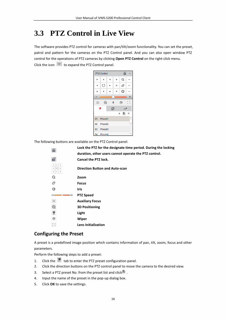
Click the icon to expand the PTZ Control panel.
The following buttons are available on the PTZ Control panel:
Lock the PTZ for the designate time period. During the locking
duration, other users cannot operate the PTZ control.
Cancel the PTZ lock.
Direction Button and Auto-scan
Zoom
Focus
Iris
PTZ Speed
Auxiliary Focus
3D Positioning
Light
Wiper
Lens Initialization
Configuring the Preset
A preset is a predefined image position which contains information of pan, tilt, zoom, focus and other
parameters.
Perform the following steps to add a preset:
1. Click the tab to enter the PTZ preset configuration panel.
2. Click the direction buttons on the PTZ control panel to move the camera to the desired view.
3. Select a PTZ preset No. from the preset list and click .
4. Input the name of the preset in the pop-up dialog box.
5. Click OK to save the settings.
User Manual of iVMS-5200 Professional Control Client
17
To call a configured preset, double-click the preset, or select the preset and click the icon .
To edit a configured preset, select the preset from the list and click the icon .
To delete a configured preset, select the preset from the list and click the icon .
Configuring the Patrol
A patrol is a scanning track specified by a group of user-defined presets, with the scanning speed
between two presets and the dwell time at the preset separately programmable.
Before you start:
Two or more presets for one PTZ camera need to be added.
Perform the following steps to add and call a patrol:
1. Click the button to enter the PTZ patrol configuration panel.
2. Select a path No. from the drop-down list.
3. Click to add a preset, and set the dwell time and patrol speed.
4. Repeat the above operation to add other presets to the patrol.
5. Optionally, you can click or to edit or delete a preset in the patrol path.
6. Click the icon to call the patrol. To stop calling the patrol, click .
Notes:
Up to 16 patrols can be configured.
The preset dwell time can be set to 1~30 seconds, and the patrol speed can be set to level 1~40.
Configuring the Pattern
Patterns can be set to record the movement of the PTZ.
Perform the following steps to add a pattern:
1. Click the button to enter the PTZ pattern configuration panel.
2. Click to start recording of this pattern path.
3. Use the direction buttons and other buttons to control the PTZ movement.
4. Click to stop and save the pattern recording.
5. Click the icon to call the pattern. To stop calling the pattern, click .
Note: Only one pattern can be configured, and the newly-defined pattern will overwrite the previous
one.
3.4 Manual Recording and Capture
Move the mouse to the lower edge of the live view display window. The following toolbar buttons are
available:
Capture Capture the picture of the camera during live view.
Start/Stop Recording Start/Stop manual recording. The record file is stored in the PC.
Switch to Instant
Playback
Switch to the instant playback mode. You can select the playback
time.
Manual Recording in Live View
Purpose:
Manual Recording function allows you to record the live video on the Main View page manually and
the record files are stored in the local PC.
User Manual of iVMS-5200 Professional Control Client
18
Steps:
1. Move the mouse to the lower edge of the live view display window to show the toolbar.
2. Click in the toolbar of the display window or on the right-click menu to start the manual
recording. The icon turns to .
3. Click the icon to stop the manual recording.
A prompt box with the saving path of the video files you just recorded will pop up if all the
operations succeed.
Notes:
During the manual recording, an indicator appears in the upper-right corner of the display
window.
The saving path of video files can be set on the Local Configuration interface. For details, see
Chapter 14.2 File Saving Path Settings.
Viewing Local Record Files
Purpose:
The manually recorded files in live view are stored in the PC on which the Control Client is running.
You can view the record files if needed.
Steps:
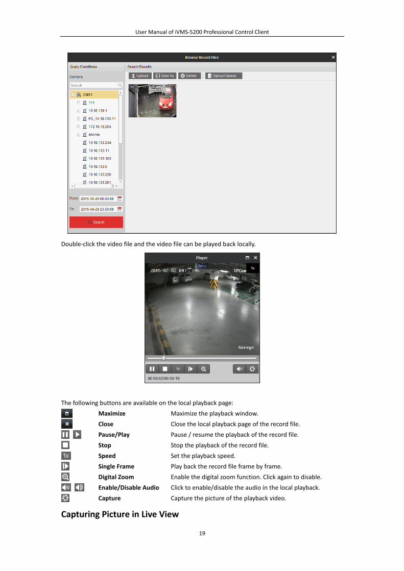
1. Click File->Open Video File to open the Record Files page.
2. Select the camera or area to be searched from the Area list.
3. Click the icon to specify the start time and end time for the search.
4. Click Search. The video files recorded between the start time and end time will be displayed.
Select the video file, and click Upload to upload the video file to the configured FTP server.
Click to start uploading the file or click Start All to start uploading all the files. You can
also click Upload Queue to check the uploading status.
Select the video file, and click Save As to save a new copy of the video file in local PC.
Select the video file, and click Delete to can delete the video file.
Note: To upload the video files to FTP server, the FTP settings need to be configured before
proceeding. For details, see Chapter 14.2 File Saving Path Settings.
User Manual of iVMS-5200 Professional Control Client
19
Double-click the video file and the video file can be played back locally.
The following buttons are available on the local playback page:
Maximize Maximize the playback window.
Close Close the local playback page of the record file.
Pause/Play Pause / resume the playback of the record file.
Stop Stop the playback of the record file.
Speed Set the playback speed.
Single Frame Play back the record file frame by frame.
Digital Zoom Enable the digital zoom function. Click again to disable.
Enable/Disable Audio Click to enable/disable the audio in the local playback.
Capture Capture the picture of the playback video.
Capturing Picture in Live View
User Manual of iVMS-5200 Professional Control Client
20
Steps:
1. Move the mouse to the lower edge of the live view display window to show the toolbar.
2. Click the icon in the toolbar of the display window or on the right-click menu.
A small window of the captured picture will be displayed to notify whether the capturing
operation is done or not.
Note: The saving path of the captured pictures can be set on the Local Configuration interface. For
details, see Chapter 14.2 File Saving Path Settings.
Viewing Captured Pictures
Purpose:
The captured pictures in live view are stored in the PC on which the Control Client is running. You can
view the captured pictures if needed.
Steps:
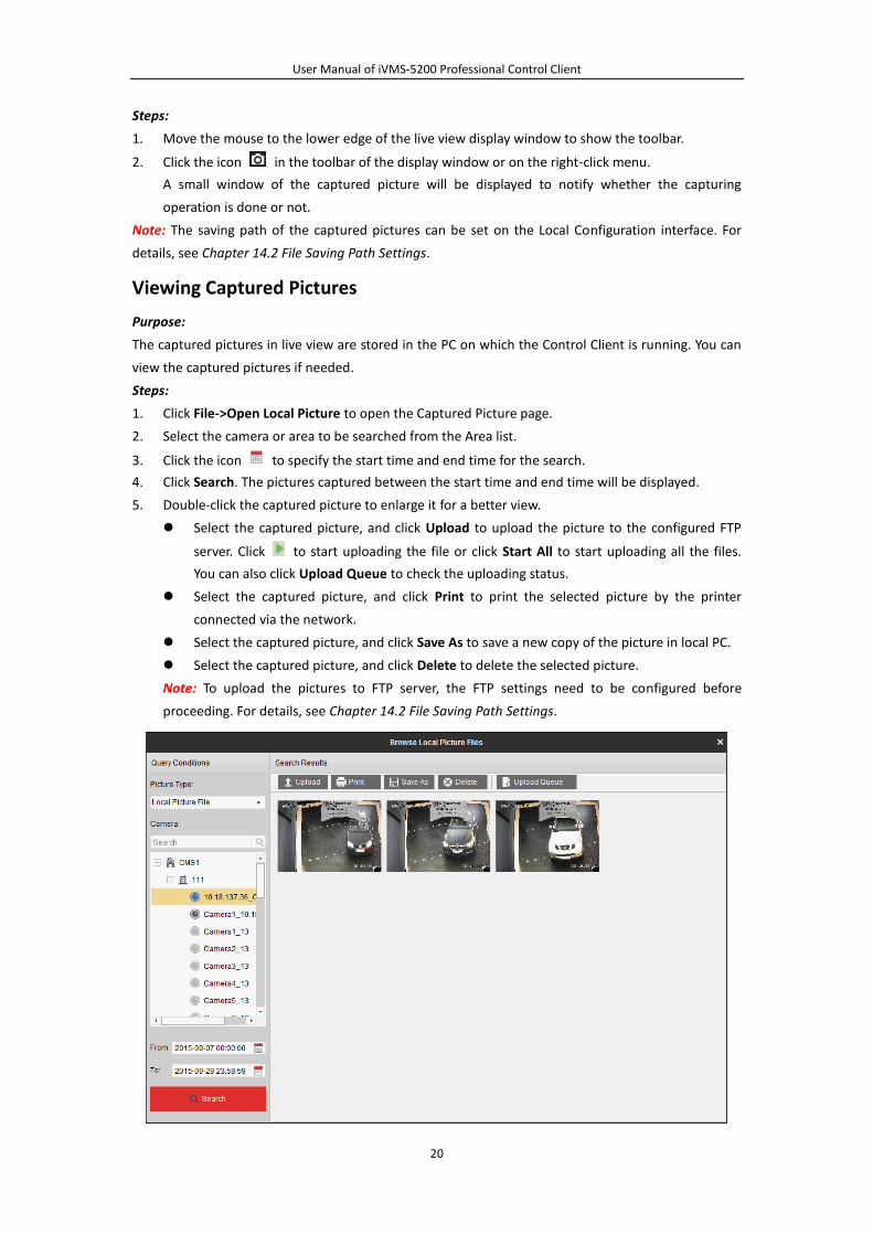
1. Click File->Open Local Picture to open the Captured Picture page.
2. Select the camera or area to be searched from the Area list.
3. Click the icon to specify the start time and end time for the search.
4. Click Search. The pictures captured between the start time and end time will be displayed.
5. Double-click the captured picture to enlarge it for a better view.
Select the captured picture, and click Upload to upload the picture to the configured FTP
server. Click to start uploading the file or click Start All to start uploading all the files.
You can also click Upload Queue to check the uploading status.
Select the captured picture, and click Print to print the selected picture by the printer
connected via the network.
Select the captured picture, and click Save As to save a new copy of the picture in local PC.
Select the captured picture, and click Delete to delete the selected picture.
Note: To upload the pictures to FTP server, the FTP settings need to be configured before
proceeding. For details, see Chapter 14.2 File Saving Path Settings.
User Manual of iVMS-5200 Professional Control Client
21
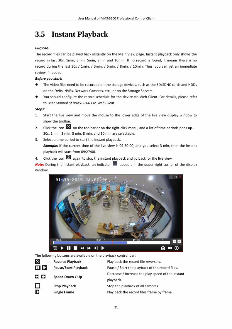
3.5 Instant Playback
Purpose:
The record files can be played back instantly on the Main View page. Instant playback only shows the
record in last 30s, 1min, 3min, 5min, 8min and 10min. If no record is found, it means there is no
record during the last 30s / 1min. / 3min. / 5min. / 8min. / 10min. Thus, you can get an immediate
review if needed.
Before you start:
The video files need to be recorded on the storage devices, such as the SD/SDHC cards and HDDs
on the DVRs, NVRs, Network Cameras, etc., or on the Storage Servers.
You should configure the record schedule for the device via Web Client. For details, please refer
to User Manual of iVMS-5200 Pro Web Client.
Steps:
1. Start the live view and move the mouse to the lower edge of the live view display window to
show the toolbar.
2. Click the icon on the toolbar or on the right-click menu, and a list of time periods pops up.
30s, 1 min, 3 min, 5 min, 8 min, and 10 min are selectable.
3. Select a time period to start the instant playback.
Example: If the current time of the live view is 09:30:00, and you select 3 min, then the instant
playback will start from 09:27:00.
4. Click the icon again to stop the instant playback and go back for the live view.
Note: During the instant playback, an indicator appears in the upper-right corner of the display
window.
The following buttons are available on the playback control bar:
Reverse Playback Play back the record file reversely.
Pause/Start Playback Pause / Start the playback of the record files.
Speed Down / Up Decrease / Increase the play speed of the instant
playback.
Stop Playback Stop the playback of all cameras.
Single Frame Play back the record files frame by frame.
User Manual of iVMS-5200 Professional Control Client
22
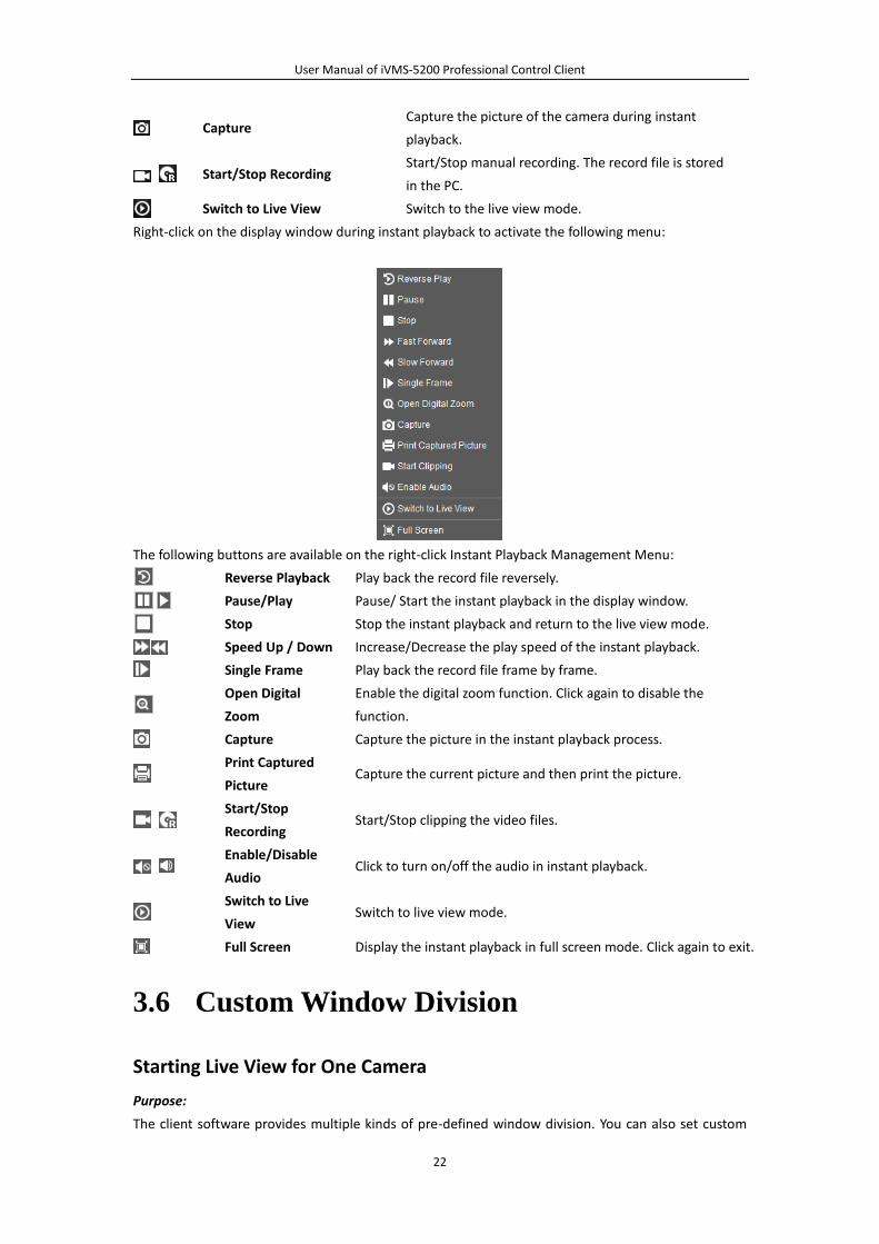
Capture Capture the picture of the camera during instant
playback.
Start/Stop Recording Start/Stop manual recording. The record file is stored
in the PC.
Switch to Live View Switch to the live view mode.
Right-click on the display window during instant playback to activate the following menu:
The following buttons are available on the right-click Instant Playback Management Menu:
Reverse Playback Play back the record file reversely.
Pause/Play Pause/ Start the instant playback in the display window.
Stop Stop the instant playback and return to the live view mode.
Speed Up / Down Increase/Decrease the play speed of the instant playback.
Single Frame Play back the record file frame by frame.
Open Digital
Zoom
Enable the digital zoom function. Click again to disable the
function.
Capture Capture the picture in the instant playback process.
Print Captured
Picture Capture the current picture and then print the picture.
Start/Stop
Recording Start/Stop clipping the video files.
Enable/Disable
Audio Click to turn on/off the audio in instant playback.
Switch to Live
View Switch to live view mode.
Full Screen Display the instant playback in full screen mode. Click again to exit.
3.6 Custom Window Division
Starting Live View for One Camera
Purpose:
The client software provides multiple kinds of pre-defined window division. You can also set custom
User Manual of iVMS-5200 Professional Control Client
23
window division as desired.
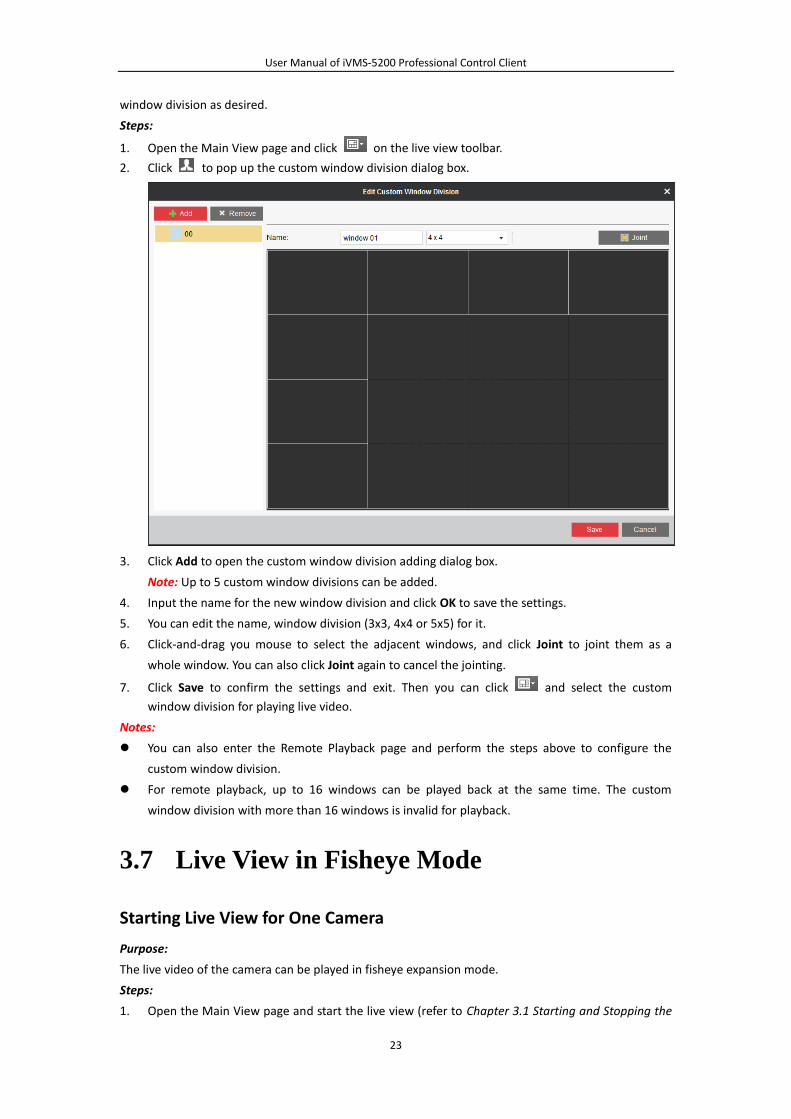
Steps:
1. Open the Main View page and click on the live view toolbar.
2. Click to pop up the custom window division dialog box.
3. Click Add to open the custom window division adding dialog box.
Note: Up to 5 custom window divisions can be added.
4. Input the name for the new window division and click OK to save the settings.
5. You can edit the name, window division (3x3, 4x4 or 5x5) for it.
6. Click-and-drag you mouse to select the adjacent windows, and click Joint to joint them as a
whole window. You can also click Joint again to cancel the jointing.
7. Click Save to confirm the settings and exit. Then you can click and select the custom
window division for playing live video.
Notes:
You can also enter the Remote Playback page and perform the steps above to configure the
custom window division.
For remote playback, up to 16 windows can be played back at the same time. The custom
window division with more than 16 windows is invalid for playback.
3.7 Live View in Fisheye Mode
Starting Live View for One Camera
Purpose:
The live video of the camera can be played in fisheye expansion mode.
Steps:
1. Open the Main View page and start the live view (refer to Chapter 3.1 Starting and Stopping the
User Manual of iVMS-5200 Professional Control Client
24
Live View).
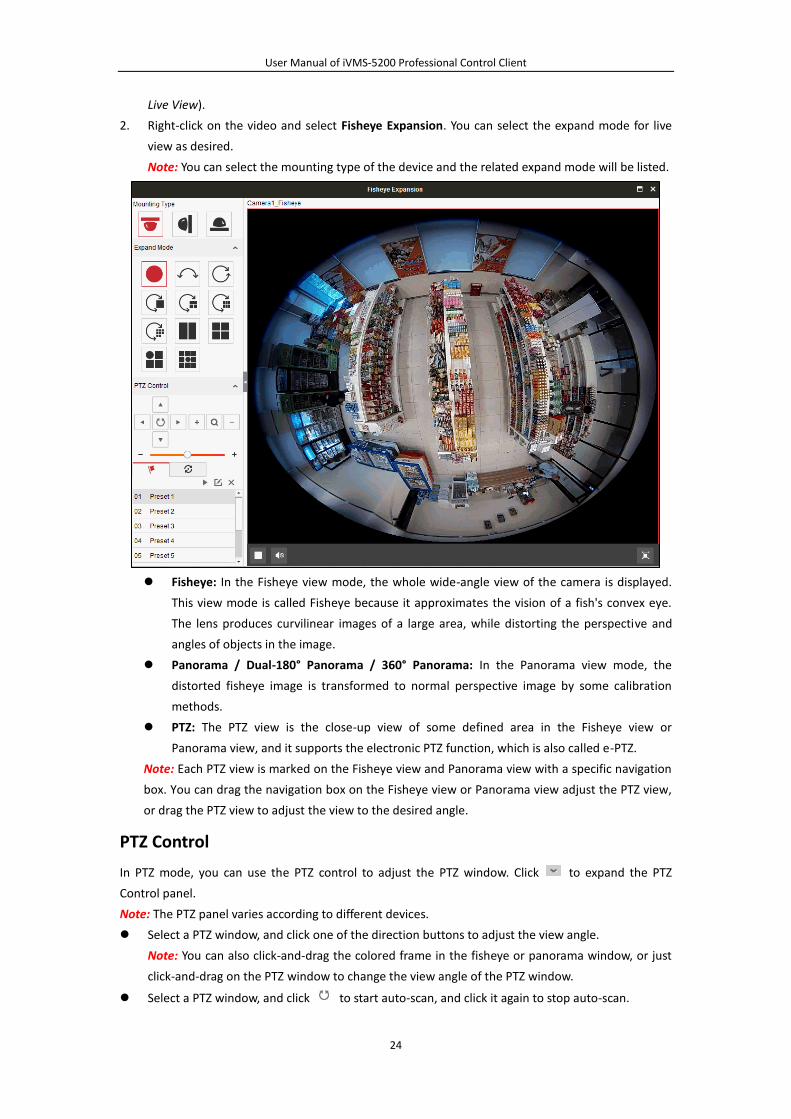
2. Right-click on the video and select Fisheye Expansion. You can select the expand mode for live
view as desired.
Note: You can select the mounting type of the device and the related expand mode will be listed.
Fisheye: In the Fisheye view mode, the whole wide-angle view of the camera is displayed.
This view mode is called Fisheye because it approximates the vision of a fish's convex eye.
The lens produces curvilinear images of a large area, while distorting the perspective and
angles of objects in the image.
Panorama / Dual-180° Panorama / 360° Panorama: In the Panorama view mode, the
distorted fisheye image is transformed to normal perspective image by some calibration
methods.
PTZ: The PTZ view is the close-up view of some defined area in the Fisheye view or
Panorama view, and it supports the electronic PTZ function, which is also called e-PTZ.
Note: Each PTZ view is marked on the Fisheye view and Panorama view with a specific navigation
box. You can drag the navigation box on the Fisheye view or Panorama view adjust the PTZ view,
or drag the PTZ view to adjust the view to the desired angle.
PTZ Control
In PTZ mode, you can use the PTZ control to adjust the PTZ window. Click to expand the PTZ
Control panel.
Note: The PTZ panel varies according to different devices.
Select a PTZ window, and click one of the direction buttons to adjust the view angle.
Note: You can also click-and-drag the colored frame in the fisheye or panorama window, or just
click-and-drag on the PTZ window to change the view angle of the PTZ window.
Select a PTZ window, and click to start auto-scan, and click it again to stop auto-scan.
User Manual of iVMS-5200 Professional Control Client
25
: Drag the slider to adjust the speed for PTZ movement.
: Zoom in or zoom out the selected PTZ window. Or you can scroll the mouse wheel
to zoom in or zoom out.
Preset
A preset is a user-defined monitor position/point. You can simply call the preset No. to change the
monitor scene to the defined position. Please follow the steps below to configure the preset.
Steps:
1. Click the tab to enter the PTZ preset configuration panel.
2. Select a PTZ window, and adjust the scene to the place you want to mark as a preset.
3. Select a PTZ preset No. from the preset list and click .
4. Input the name of the preset in the pop-up dialog box.
5. Click OK to save the settings.
To call a configured preset, double-click the preset, or select the preset and click the icon .
To edit a configured preset, select the preset from the list and click the icon .
To delete a configured preset, select the preset from the list and click the icon .
Patrol
A patrol is a scanning track specified by a group of user-defined presets, with the scanning speed
between two presets and the dwell time at the preset separately programmable. Please follow the
steps below to configure the patrol.
Note: At least 2 presets have to be configured before you configure the patrol.
Steps:
1. Click the button to enter the PTZ patrol configuration panel.
2. Select a path No. from the drop-down list.
3. Click to add a preset, and set the dwell time and patrol speed.
4. Repeat the above operation to add other presets to the patrol.
5. Optionally, you can click or to edit or delete a preset in the patrol path.
6. Click the icon to call the patrol. To stop calling the patrol, click .
Notes:
Up to 256 presets can be configured.
Up to 16 patrols can be configured.
The dwell time ranges from 1 to 30s.
The patrol speed ranges from 1 to 40.
3.8 Live Viewing the Video from Mobile
Terminal
Purpose:
The live video of the mobile terminal which has installed with iVMS-5200 Pro Mobile Client can be
uploaded for viewing.
Before you start:
User Manual of iVMS-5200 Professional Control Client
26
An area which contains mobile terminal and is configured with SMS should be added to the
iVMS-5200 Pro. For adding mobile terminal and managing the area, refer to the User Manual of
iVMS-5200 Pro Web Client.
The mobile terminal needs to be installed with iVMS-5200 Pro Mobile Client and properly
configured with video upload. For detailed configuration about video upload, refer to the User
Manual of iVMS-5200 Pro Mobile Client.
Two modes are available for viewing the live video from the mobile terminal.
Request the Video Upload: Actively ask for the Mobile Client to upload the video for live view.
Receive the Video Upload Request: Allow the request from the Mobile Client for uploading the video.
Requesting the Video Upload
Steps:
1. Open the Main View page.
2. (Optional) Click and select the window division mode for live view.
3. Click-and-drag the mobile terminal to the display window,
or double-click the mobile terminal name after selecting the display window to start the live
view.
Note: If the Mobile Client does not enable to accept the video uploading request automatically, you
can only view the live video after the request allowed by the Mobile Client.
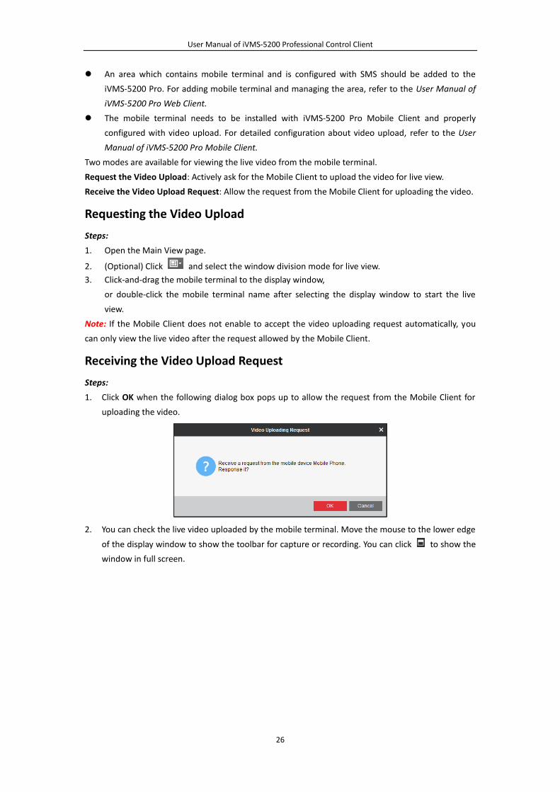
Receiving the Video Upload Request
Steps:
1. Click OK when the following dialog box pops up to allow the request from the Mobile Client for
uploading the video.
2. You can check the live video uploaded by the mobile terminal. Move the mouse to the lower edge
of the display window to show the toolbar for capture or recording. You can click to show the
window in full screen.
User Manual of iVMS-5200 Professional Control Client
27
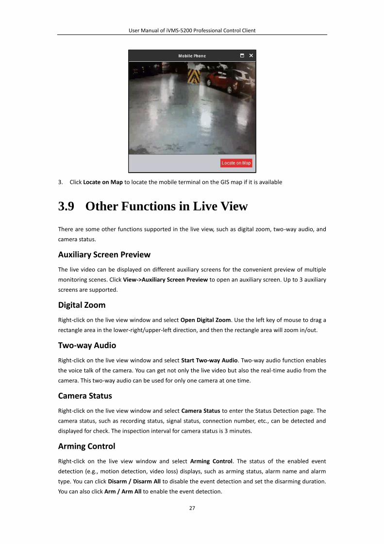
3. Click Locate on Map to locate the mobile terminal on the GIS map if it is available
3.9 Other Functions in Live View
There are some other functions supported in the live view, such as digital zoom, two-way audio, and
camera status.
Auxiliary Screen Preview
The live video can be displayed on different auxiliary screens for the convenient preview of multiple
monitoring scenes. Click View->Auxiliary Screen Preview to open an auxiliary screen. Up to 3 auxiliary
screens are supported.
Digital Zoom
Right-click on the live view window and select Open Digital Zoom. Use the left key of mouse to drag a
rectangle area in the lower-right/upper-left direction, and then the rectangle area will zoom in/out.
Two-way Audio
Right-click on the live view window and select Start Two-way Audio. Two-way audio function enables
the voice talk of the camera. You can get not only the live video but also the real-time audio from the
camera. This two-way audio can be used for only one camera at one time.
Camera Status
Right-click on the live view window and select Camera Status to enter the Status Detection page. The
camera status, such as recording status, signal status, connection number, etc., can be detected and
displayed for check. The inspection interval for camera status is 3 minutes.
Arming Control
Right-click on the live view window and select Arming Control. The status of the enabled event
detection (e.g., motion detection, video loss) displays, such as arming status, alarm name and alarm
type. You can click Disarm / Disarm All to disable the event detection and set the disarming duration.
You can also click Arm / Arm All to enable the event detection.
User Manual of iVMS-5200 Professional Control Client
28
Chapter 4 Remote Playback
Purpose:
The record files stored on the local device or the Storage Server can be searched by area, camera or
triggering event, and then can be played back remotely.
Before you start:
You should set the record settings for the camera via the Web Client. For details, please refer to the
User Manual of iVMS-5200 Pro Web Client.
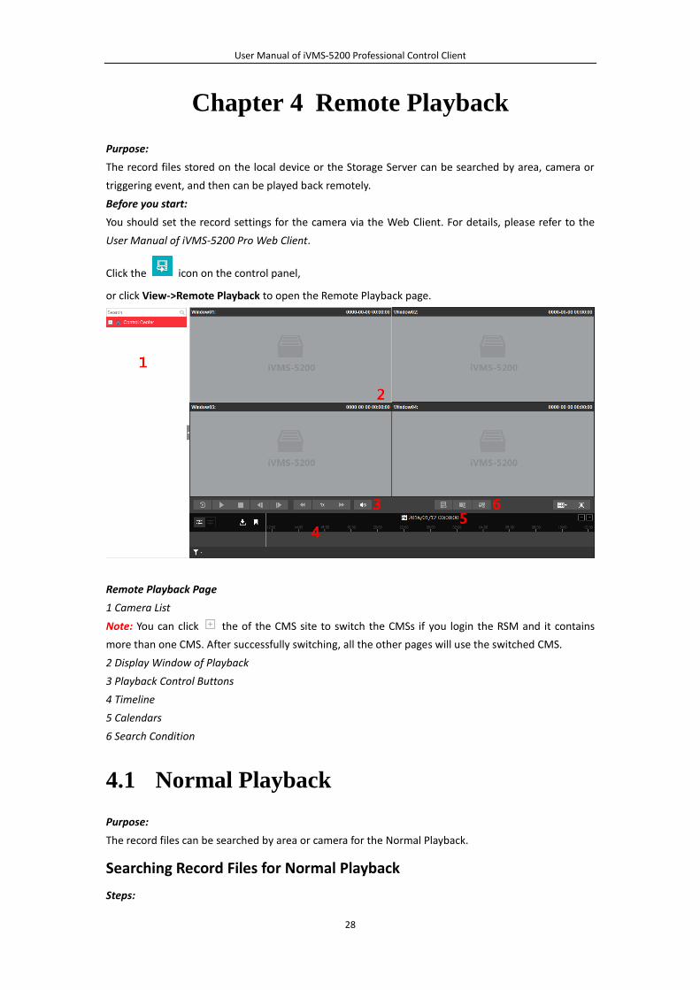
Click the icon on the control panel,
or click View->Remote Playback to open the Remote Playback page.
Remote Playback Page
1 Camera List
Note: You can click the of the CMS site to switch the CMSs if you login the RSM and it contains
more than one CMS. After successfully switching, all the other pages will use the switched CMS.
2 Display Window of Playback
3 Playback Control Buttons
4 Timeline
5 Calendars
6 Search Condition
4.1 Normal Playback
Purpose:
The record files can be searched by area or camera for the Normal Playback.
Searching Record Files for Normal Playback
Steps:
User Manual of iVMS-5200 Professional Control Client
29
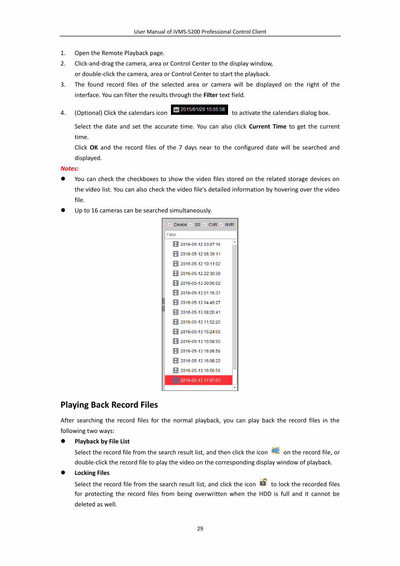
1. Open the Remote Playback page.
2. Click-and-drag the camera, area or Control Center to the display window,
or double-click the camera, area or Control Center to start the playback.
3. The found record files of the selected area or camera will be displayed on the right of the
interface. You can filter the results through the Filter text field.
4. (Optional) Click the calendars icon to activate the calendars dialog box.
Select the date and set the accurate time. You can also click Current Time to get the current
time.
Click OK and the record files of the 7 days near to the configured date will be searched and
displayed.
Notes:
You can check the checkboxes to show the video files stored on the related storage devices on
the video list. You can also check the video file's detailed information by hovering over the video
file.
Up to 16 cameras can be searched simultaneously.
Playing Back Record Files
After searching the record files for the normal playback, you can play back the record files in the
following two ways:
Playback by File List
Select the record file from the search result list, and then click the icon on the record file, or
double-click the record file to play the video on the corresponding display window of playback.
Locking Files
Select the record file from the search result list, and click the icon to lock the recorded files
for protecting the record files from being overwritten when the HDD is full and it cannot be
deleted as well.
User Manual of iVMS-5200 Professional Control Client
30
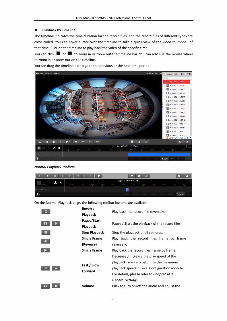
Playback by Timeline
The timeline indicates the time duration for the record files, and the record files of different types are
color coded. You can hover cursor over the timeline to take a quick view of the video thumbnail of
that time. Click on the timeline to play back the video of the specific time.
You can click or to zoom in or zoom out the timeline bar. You can also use the mouse wheel
to zoom in or zoom out on the timeline.
You can drag the timeline bar to go to the previous or the next time period.
Normal Playback Toolbar:
On the Normal Playback page, the following toolbar buttons are available:
Reverse
Playback Play back the record file reversely.
Pause/Start
Playback Pause / Start the playback of the record files.
Stop Playback Stop the playback of all cameras.
Single Frame
(Reverse)
Play back the record files frame by frame
reversely.
Single Frame Play back the record files frame by frame.
Fast / Slow
Forward
Decrease / Increase the play speed of the
playback. You can customize the maximum
playback speed in Local Configuration module.
For details, please refer to Chapter 14.1
General Settings.
Volume Click to turn on/off the audio and adjust the
User Manual of iVMS-5200 Professional Control Client
31
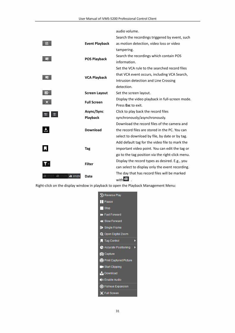
audio volume.
Event Playback
Search the recordings triggered by event, such
as motion detection, video loss or video
tampering.
POS Playback Search the recordings which contain POS
information.
VCA Playback
Set the VCA rule to the searched record files
that VCA event occurs, including VCA Search,
Intrusion detection and Line Crossing
detection.
Screen Layout Set the screen layout.
Full Screen Display the video playback in full-screen mode.
Press Esc to exit.
Async/Sync
Playback
Click to play back the record files
synchronously/asynchronously.
Download
Download the record files of the camera and
the record files are stored in the PC. You can
select to download by file, by date or by tag.
Tag
Add default tag for the video file to mark the
important video point. You can edit the tag or
go to the tag position via the right-click menu.
Filter Display the record types as desired. E.g., you
can select to display only the event recording.
Date The day that has record files will be marked
with .
Right-click on the display window in playback to open the Playback Management Menu:
User Manual of iVMS-5200 Professional Control Client
32
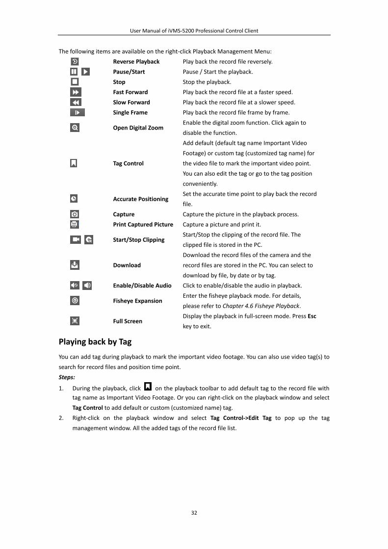
The following items are available on the right-click Playback Management Menu:
Reverse Playback Play back the record file reversely.
Pause/Start Pause / Start the playback.
Stop Stop the playback.
Fast Forward Play back the record file at a faster speed.
Slow Forward Play back the record file at a slower speed.
Single Frame Play back the record file frame by frame.
Open Digital Zoom Enable the digital zoom function. Click again to
disable the function.
Tag Control
Add default (default tag name Important Video
Footage) or custom tag (customized tag name) for
the video file to mark the important video point.
You can also edit the tag or go to the tag position
conveniently.
Accurate Positioning Set the accurate time point to play back the record
file.
Capture Capture the picture in the playback process.
Print Captured Picture Capture a picture and print it.
Start/Stop Clipping Start/Stop the clipping of the record file. The
clipped file is stored in the PC.
Download
Download the record files of the camera and the
record files are stored in the PC. You can select to
download by file, by date or by tag.
Enable/Disable Audio Click to enable/disable the audio in playback.
Fisheye Expansion Enter the fisheye playback mode. For details,
please refer to Chapter 4.6 Fisheye Playback.
Full Screen Display the playback in full-screen mode. Press Esc
key to exit.
Playing back by Tag
You can add tag during playback to mark the important video footage. You can also use video tag(s) to
search for record files and position time point.
Steps:
1. During the playback, click on the playback toolbar to add default tag to the record file with
tag name as Important Video Footage. Or you can right-click on the playback window and select
Tag Control to add default or custom (customized name) tag.
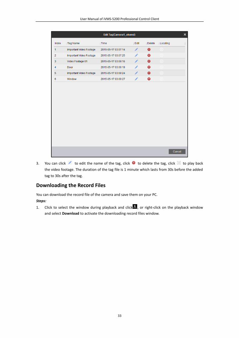
2. Right-click on the playback window and select Tag Control->Edit Tag to pop up the tag
management window. All the added tags of the record file list.
User Manual of iVMS-5200 Professional Control Client
33
3. You can click to edit the name of the tag, click to delete the tag, click to play back
the video footage. The duration of the tag file is 1 minute which lasts from 30s before the added
tag to 30s after the tag.
Downloading the Record Files
You can download the record file of the camera and save them on your PC.
Steps:
1. Click to select the window during playback and click , or right-click on the playback window
and select Download to activate the downloading record files window.
User Manual of iVMS-5200 Professional Control Client
34
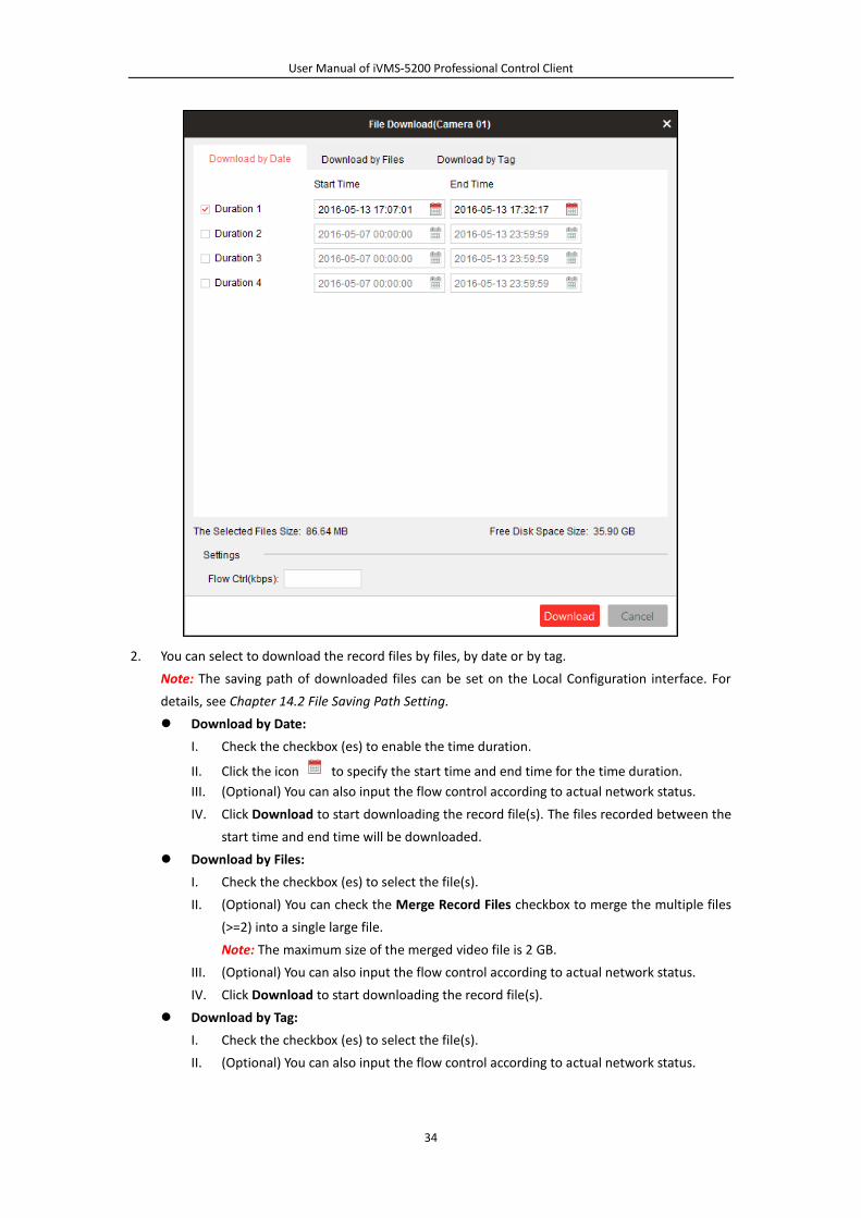
2. You can select to download the record files by files, by date or by tag.
Note: The saving path of downloaded files can be set on the Local Configuration interface. For
details, see Chapter 14.2 File Saving Path Setting.
Download by Date:
I. Check the checkbox (es) to enable the time duration.
II. Click the icon to specify the start time and end time for the time duration.
III. (Optional) You can also input the flow control according to actual network status.
IV. Click Download to start downloading the record file(s). The files recorded between the
start time and end time will be downloaded.
Download by Files:
I. Check the checkbox (es) to select the file(s).
II. (Optional) You can check the Merge Record Files checkbox to merge the multiple files
(>=2) into a single large file.
Note: The maximum size of the merged video file is 2 GB.
III. (Optional) You can also input the flow control according to actual network status.
IV. Click Download to start downloading the record file(s).
Download by Tag:
I. Check the checkbox (es) to select the file(s).
II. (Optional) You can also input the flow control according to actual network status.
User Manual of iVMS-5200 Professional Control Client
35
III. Click Download to start downloading the record file(s).The duration of the tag file is 1
minute which lasts from 30s before the added tag to 30s after the tag.
4.2 Event Playback
Purpose:
The recordings triggered by event, such as motion detection, video loss or face detection, can be
searched for Event Playback and this function requires the support of the connected device.
Searching Record Files for Event Playback
Steps:
1. Open the Remote Playback page.
2. Select the camera and start the normal playback. Refer to Chapter 4.1 Normal Playback.
3. Click and the motion detection triggered recording will be search by default.
4. Select the event type from the drop-down list and the found record files will be displayed. You
can filter the results through the Filter text field. Or you can click to go back to the normal
playback.
5. (Optional) Click the calendars icon to activate the calendars dialog box.
Select the date and set the accurate time. You can also click Current Time to get the current
time.
Click OK and the record files of the 7 days near to the configured date will be searched and
displayed.
6. Select the record file from the search result list, and then click the icon on the record file, or
double-click the record file to play the video on the corresponding display window of playback.
Playing Back Record Files
After searching the recordings triggered by the event, you can play back the record files in the
following two ways:
Playback by File List
Select the record file from the search result list, and then click the icon in the toolbar, or
click the icon on the record file, or double-click the record file to play the video on the
corresponding display window of playback. You can also click or to go to the
previous event or next event.
Playback by Timeline
The timeline indicates the time duration for the record file. Click on the timeline to play back the
video of the specific time.
You can click or to zoom in or zoom out the timeline bar. You can also use the mouse
wheel to zoom in or zoom out on the timeline.
You can drag the timeline bar to go to the previous or the next time period.
Please refer to Chapter 4.1 Normal Playback for the description of the playback control toolbar,
right-click menu and downloading record files. Some icons may not be available for event playback.
User Manual of iVMS-5200 Professional Control Client
36
4.3 POS Playback
Purpose:
Search the recordings which contain POS information.
Note: This function should be supported by the device and the device should be configured with POS
text overlay. For details, please refer to the User Manual of the device.
Searching Record Files for POS Playback
Steps:
1. Open the Remote Playback page.
2. Select the camera and start the normal playback. Refer to Chapter 4.1 Normal Playback.
3. Click to enter the POS playback interface.
4. Enter the search conditions.
Keywords: Input the keywords that are contained in the POS information. You can input up to 3
keywords by separating each one with a space.
Filter: If you input more than one keyword for query, you can select “|” to search the POS
information containing any of the keywords, or select “&” to search the POS information
containing all of the keywords.
Case Sensitive: Check the checkbox to search the POS information with case-sensitivity.
5. Click Search and the matched files will be displayed. You can filter the results through the Filter
text field.
6. (Optional) Click the calendars icon to activate the calendars dialog box.
Select the date and set the accurate time. You can also click Current Time to get the current
time.
Click OK and the record files of the 7 days near to the configured date will be searched and
displayed.
7. Double-click a file for playback. Or you can click to go back to the normal playback.
Playing Back Record Files
After searching the recordings, you can play back the record files in the following two ways:
Playback by File List
Select the record file from the search result list, and then click the icon in the toolbar, or
click the icon on the record file, or double-click the record file to play the video on the
corresponding display window of playback.
Playback by Timeline
The timeline indicates the time duration for the record file. Click on the timeline to play back the
video of the specific time.
You can click or to zoom in or zoom out the timeline bar. You can also use the mouse
wheel to zoom in or zoom out on the timeline.
You can drag the timeline bar to go to the previous or the next time period.
Please refer to Chapter 4.1 Normal Playback for the description of the playback control toolbar,
right-click menu and downloading record files. Some icons may not be available for POS playback.

User Manual of iVMS-5200 Professional Control Client
37
4.4 Synchronous Playback
Purpose:
In synchronous playback, the record files can be played back in synchronization.
Note: Record files from up to 16 cameras can be played back simultaneously.
Steps:
1. Open the Remote Playback page.
2. Search the record files for the normal playback (refer to Chapter 4.1 Normal Playback). At least
two cameras are during playback.
3. Click in the toolbar to enable the synchronous playback. The camera under playback will
start synchronous playback.
4. To disable the synchronous playback, click the icon .
Please refer to Chapter 4.1 Normal Playback for the description of the playback control toolbar,
right-click menu and downloading record files. Some icons may not be available for synchronous
playback.
4.5 VCA Playback
Purpose:
You can set VCA rule to the searched record files and find the video that VCA event occurs, including
VCA Search, Intrusion and Line Crossing. This function helps to search out the video that you may be
more concerned, mark it with red color, and set the playback speed of the concerned video as 1X
while the unconcerned video as 8X.
VCA Search: Get all the related motion detection events that occurred in the pre-defined region.
Intrusion Detection: Detect whether there are people, vehicles and other moving objects
intruding into the pre-defined region.
Line Crossing Detection: Bi-directionally detect people, vehicles and other moving objects that
cross a virtual line.
Note: This function should be supported by the device.
User Manual of iVMS-5200 Professional Control Client
38
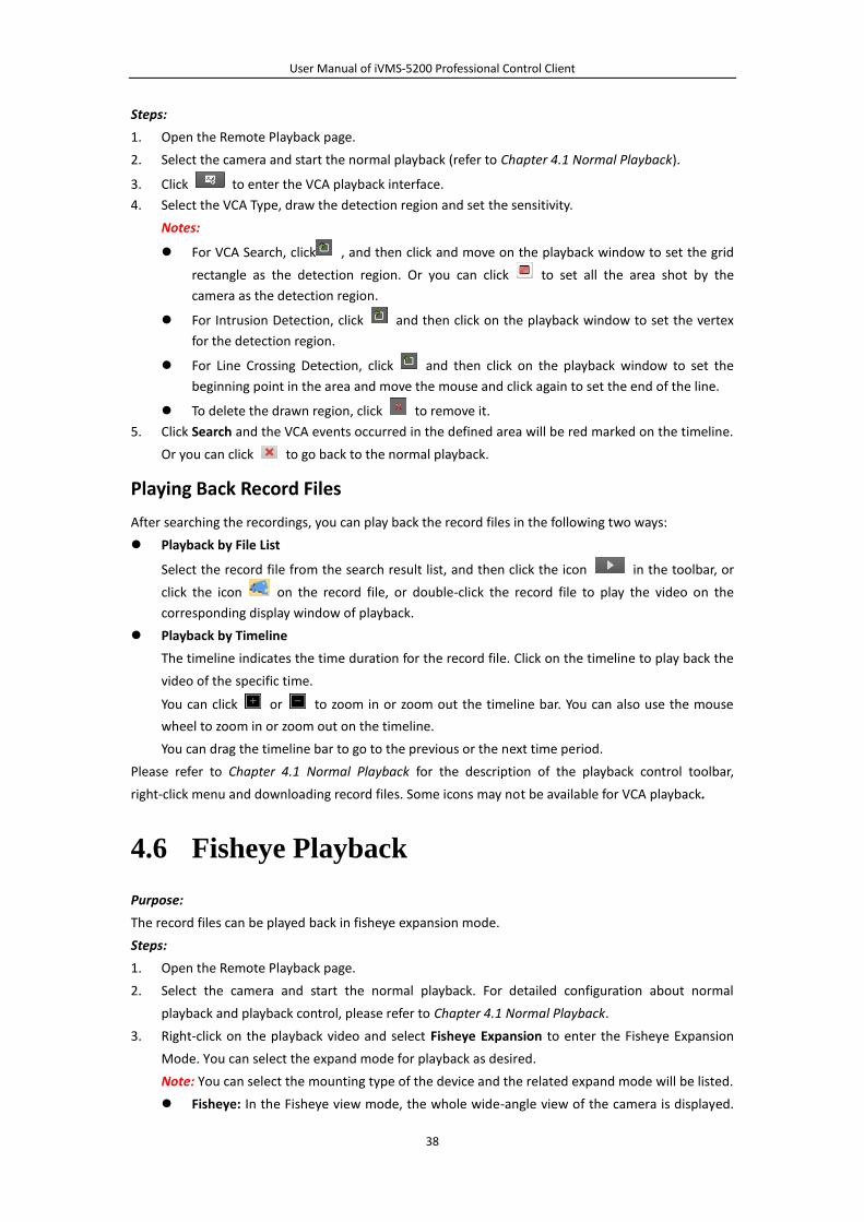
Steps:
1. Open the Remote Playback page.
2. Select the camera and start the normal playback (refer to Chapter 4.1 Normal Playback).
3. Click to enter the VCA playback interface.
4. Select the VCA Type, draw the detection region and set the sensitivity.
Notes:
For VCA Search, click , and then click and move on the playback window to set the grid
rectangle as the detection region. Or you can click to set all the area shot by the
camera as the detection region.
For Intrusion Detection, click and then click on the playback window to set the vertex
for the detection region.
For Line Crossing Detection, click and then click on the playback window to set the
beginning point in the area and move the mouse and click again to set the end of the line.
To delete the drawn region, click to remove it.
5. Click Search and the VCA events occurred in the defined area will be red marked on the timeline.
Or you can click to go back to the normal playback.
Playing Back Record Files
After searching the recordings, you can play back the record files in the following two ways:
Playback by File List
Select the record file from the search result list, and then click the icon in the toolbar, or
click the icon on the record file, or double-click the record file to play the video on the
corresponding display window of playback.
Playback by Timeline
The timeline indicates the time duration for the record file. Click on the timeline to play back the
video of the specific time.
You can click or to zoom in or zoom out the timeline bar. You can also use the mouse
wheel to zoom in or zoom out on the timeline.
You can drag the timeline bar to go to the previous or the next time period.
Please refer to Chapter 4.1 Normal Playback for the description of the playback control toolbar,
right-click menu and downloading record files. Some icons may not be available for VCA playback.
4.6 Fisheye Playback
Purpose:
The record files can be played back in fisheye expansion mode.
Steps:
1. Open the Remote Playback page.
2. Select the camera and start the normal playback. For detailed configuration about normal
playback and playback control, please refer to Chapter 4.1 Normal Playback.
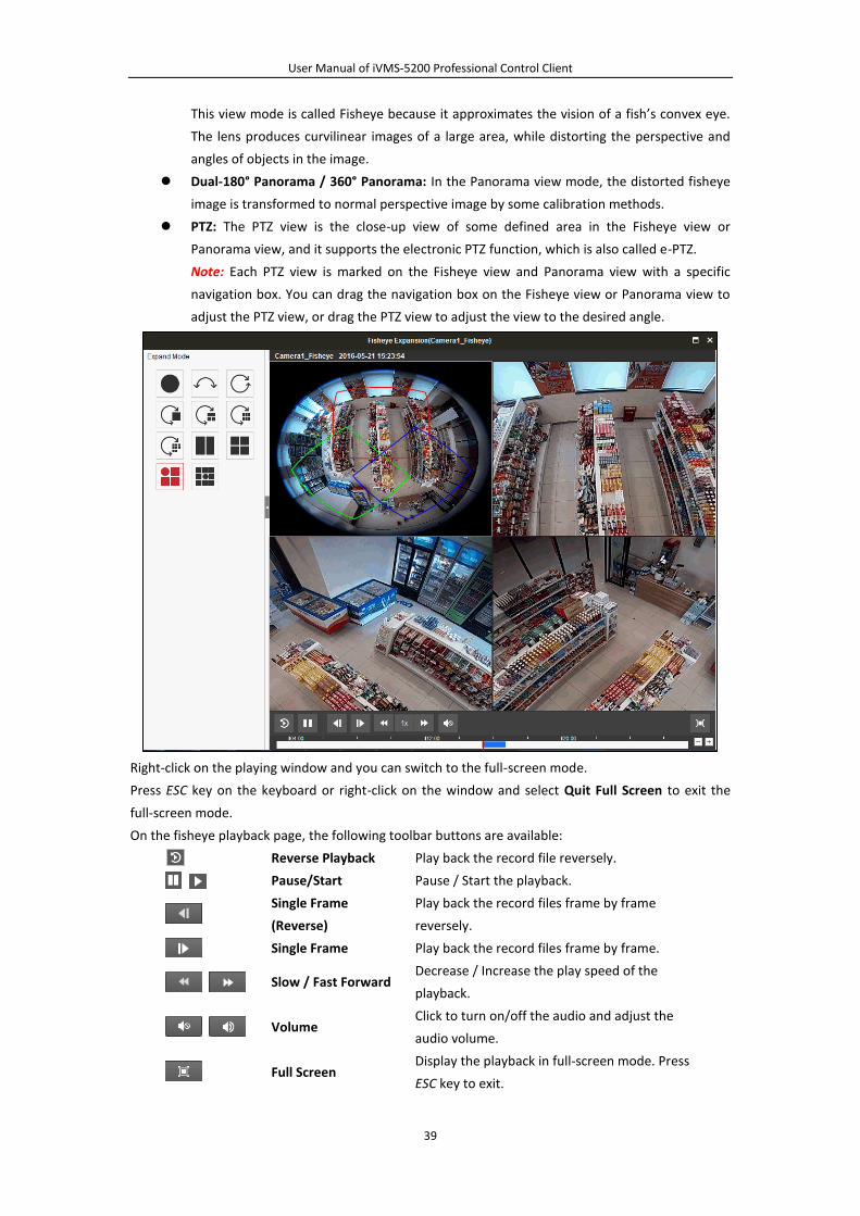
3. Right-click on the playback video and select Fisheye Expansion to enter the Fisheye Expansion
Mode. You can select the expand mode for playback as desired.
Note: You can select the mounting type of the device and the related expand mode will be listed.
Fisheye: In the Fisheye view mode, the whole wide-angle view of the camera is displayed.
User Manual of iVMS-5200 Professional Control Client
39
This view mode is called Fisheye because it approximates the vision of a fish’s convex eye.
The lens produces curvilinear images of a large area, while distorting the perspective and
angles of objects in the image.
Dual-180° Panorama / 360° Panorama: In the Panorama view mode, the distorted fisheye
image is transformed to normal perspective image by some calibration methods.
PTZ: The PTZ view is the close-up view of some defined area in the Fisheye view or
Panorama view, and it supports the electronic PTZ function, which is also called e-PTZ.
Note: Each PTZ view is marked on the Fisheye view and Panorama view with a specific
navigation box. You can drag the navigation box on the Fisheye view or Panorama view to
adjust the PTZ view, or drag the PTZ view to adjust the view to the desired angle.
Right-click on the playing window and you can switch to the full-screen mode.
Press ESC key on the keyboard or right-click on the window and select Quit Full Screen to exit the
full-screen mode.
On the fisheye playback page, the following toolbar buttons are available:
Reverse Playback Play back the record file reversely.
Pause/Start Pause / Start the playback.
Single Frame
(Reverse)
Play back the record files frame by frame
reversely.
Single Frame Play back the record files frame by frame.
Slow / Fast Forward Decrease / Increase the play speed of the
playback.
Volume Click to turn on/off the audio and adjust the
audio volume.
Full Screen Display the playback in full-screen mode. Press
ESC key to exit.
User Manual of iVMS-5200 Professional Control Client
40
Chapter 5 E-map Management
Purpose:
The E-map function gives a visual overview of the locations and distributions of the installed cameras,
alarm input devices, alarm output devices and access control devices. You can get the live view of the
cameras on the map, and you will get a notification message from the map when alarm is triggered.
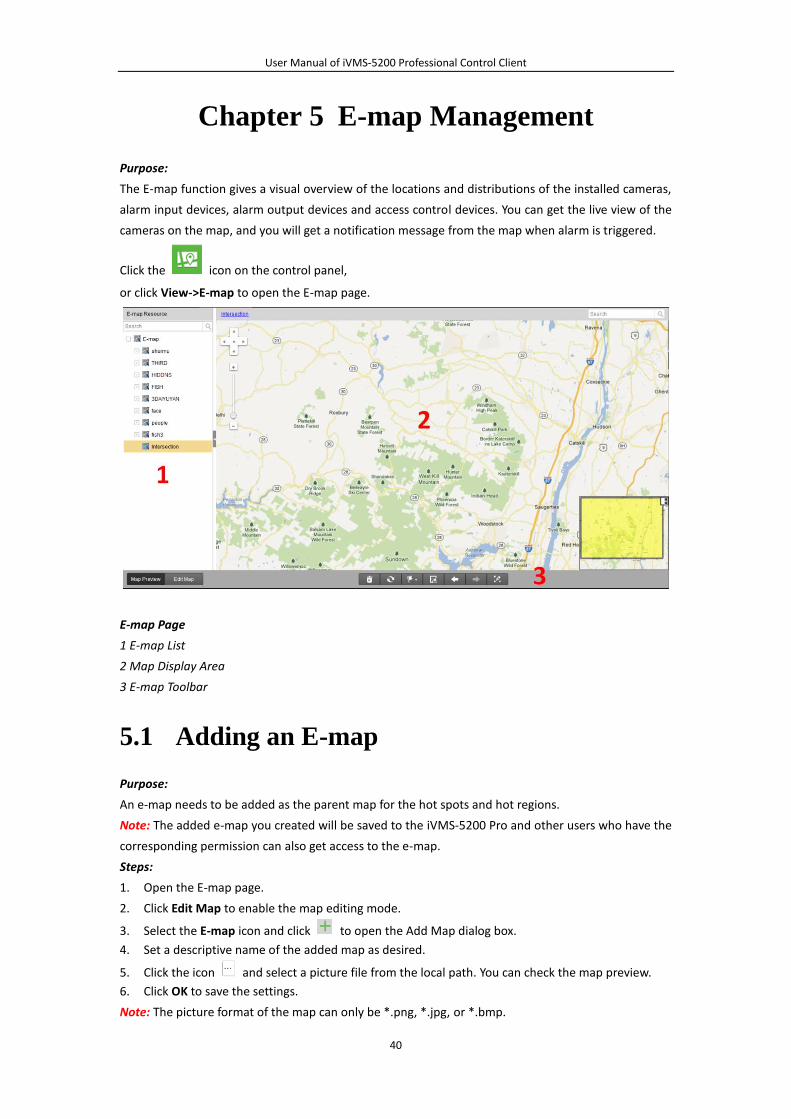
Click the icon on the control panel,
or click View->E-map to open the E-map page.
E-map Page
1 E-map List
2 Map Display Area
3 E-map Toolbar
5.1 Adding an E-map
Purpose:
An e-map needs to be added as the parent map for the hot spots and hot regions.
Note: The added e-map you created will be saved to the iVMS-5200 Pro and other users who have the
corresponding permission can also get access to the e-map.
Steps:
1. Open the E-map page.
2. Click Edit Map to enable the map editing mode.
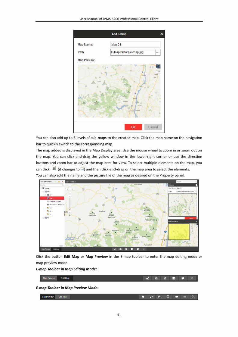
3. Select the E-map icon and click to open the Add Map dialog box.
4. Set a descriptive name of the added map as desired.
5. Click the icon and select a picture file from the local path. You can check the map preview.
6. Click OK to save the settings.
Note: The picture format of the map can only be *.png, *.jpg, or *.bmp.
User Manual of iVMS-5200 Professional Control Client
41
You can also add up to 5 levels of sub-maps to the created map. Click the map name on the navigation
bar to quickly switch to the corresponding map.
The map added is displayed in the Map Display area. Use the mouse wheel to zoom in or zoom out on
the map. You can click-and-drag the yellow window in the lower-right corner or use the direction
buttons and zoom bar to adjust the map area for view. To select multiple elements on the map, you
can click (it changes to ) and then click-and-drag on the map area to select the elements.
You can also edit the name and the picture file of the map as desired on the Property panel.
Click the button Edit Map or Map Preview in the E-map toolbar to enter the map editing mode or
map preview mode.
E-map Toolbar in Map Editing Mode:
E-map Toolbar in Map Preview Mode:

User Manual of iVMS-5200 Professional Control Client
42
The following table introduces the buttons on the E-map page:
Add Map Add a new map.
Modify Map Edit the map information, including the map name
and file path.
Delete Map Delete the current map.
Add Camera Hot Spot Add a camera as the hot spot on the map.
Add Alarm Input Hot
Spot
Add an alarm output device as the hot spot on the
map.
Add Alarm Output Hot
Spot
Add an alarm output device as the hot spot on the
map.
Add Hot Region Add an existing map as the hot region on the map.
Add Label Add a label with description to the map, hot spot or
hot region.
Delete Delete the selected hot spot or region.
Clear Alarm Info Clear the alarm information displayed on the map.
Refresh Refresh all the e-map information.
Preset Display the added presets of the all the maps.
Save as Preset Save the current scene as a preset.
Previous The client can remember the switching records of
the maps. Click to go to the previous record.
Next The client can remember the switching records of
the maps. Click to go to the next record.
Capture & Edit
Capture the current scene including the elements
(e.g., camera, alarm input), edit on the captured
picture, and save it to the local PC.
5.2 Hot Spot Function
Purpose:
The cameras, alarm inputs, and alarm outputs can be added on the map and are called the hot spots.
The hot spots show the locations of the cameras, alarm inputs, and alarm outputs, and you can also
get the alarm information of the surveillance scenarios through the hot spots.
5.2.1 Adding the Hot Spot
Adding Cameras as Hot Spots
Steps:
1. Click the Edit Map button in the E-map toolbar to enter the map editing mode.
2. Select a map and click the icon in the toolbar to open the Add Hot Spot dialog box.
3. Check the checkbox (es) to select the camera(s) to be added. You can also search the camera by
entering the key words in the Linked Camera filed.
User Manual of iVMS-5200 Professional Control Client
43
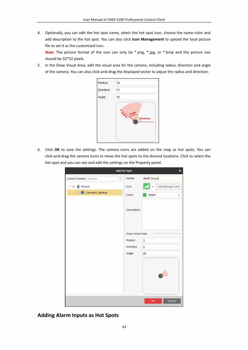
4. Optionally, you can edit the hot spot name, select the hot spot icon, choose the name color and
add description to the hot spot. You can also click Icon Management to upload the local picture
file to set it as the customized icon.
Note: The picture format of the icon can only be *.png, *.jpg, or *.bmp and the picture size
should be 32*32 pixels.
5. In the Draw Visual Area, edit the visual area for the camera, including radius, direction and angle
of the camera. You can also click-and-drag the displayed sector to adjust the radius and direction.
6. Click OK to save the settings. The camera icons are added on the map as hot spots. You can
click-and-drag the camera icons to move the hot spots to the desired locations. Click to select the
hot spot and you can see and edit the settings on the Property panel.
Adding Alarm Inputs as Hot Spots

User Manual of iVMS-5200 Professional Control Client
44
Steps:
1. Click the Edit Map button in the E-map toolbar to enter the map editing mode.
2. Select a map and click the icon in the toolbar to open the Add Hot Spot dialog box.
3. Check the checkbox (es) to select the alarm input(s) to be added. You can also search the alarm
input by entering the key words in the Linked Alarm Input filed.
4. Optionally, you can edit the hot spot name, select the hot spot icon, choose the name color and
add description to the hot spot. You can also click Icon Management to upload the local picture
file to set it as the customized icon.
Note: The picture format of the icon can only be *.png, *.jpg, or *.bmp and the picture size
should be 32*32 pixels.
5. Click OK to save the settings. The alarm input icons are added on the map as hot spots. You can
click-and-drag the alarm input icons to move the hot spots to the desired locations. Click to
select the hot spot and you can see and edit the settings on the Property panel.
Adding Alarm Outputs as Hot Spots
Steps:
1. Click the Edit Map button in the E-map toolbar to enter the map editing mode.
2. Select a map and click the icon in the toolbar to open the Add Hot Spot dialog box.
3. Check the checkbox (es) to select the alarm output(s) to be added. You can also search the alarm
output by entering the key words in the Linked Alarm Output filed.
4. Optionally, you can edit the hot spot name, select the hot spot icon, choose the name color and
add description to the hot spot. You can also click Icon Management to upload the local picture
file to set it as the customized icon.
Note: The picture format of the icon can only be *.png, *.jpg, or *.bmp and the picture size
should be 32*32 pixels.
5. Click OK to save the settings. The alarm output icons are added on the map as hot spots. You can
click-and-drag the alarm input icons to move the hot spots to the desired locations. Click to
select the hot spot and you can see and edit the settings on the Property panel.
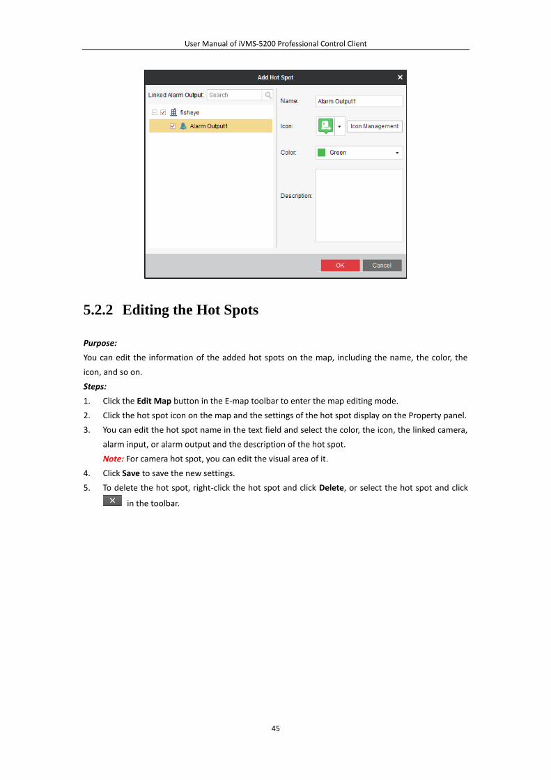
User Manual of iVMS-5200 Professional Control Client
45
5.2.2 Editing the Hot Spots
Purpose:
You can edit the information of the added hot spots on the map, including the name, the color, the
icon, and so on.
Steps:
1. Click the Edit Map button in the E-map toolbar to enter the map editing mode.
2. Click the hot spot icon on the map and the settings of the hot spot display on the Property panel.
3. You can edit the hot spot name in the text field and select the color, the icon, the linked camera,
alarm input, or alarm output and the description of the hot spot.
Note: For camera hot spot, you can edit the visual area of it.
4. Click Save to save the new settings.
5. To delete the hot spot, right-click the hot spot and click Delete, or select the hot spot and click
in the toolbar.
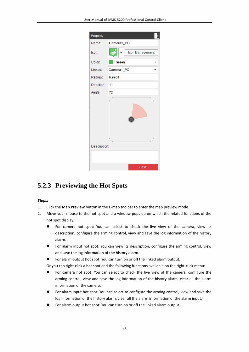
User Manual of iVMS-5200 Professional Control Client
46
5.2.3 Previewing the Hot Spots
Steps:
1. Click the Map Preview button in the E-map toolbar to enter the map preview mode.
2. Move your mouse to the hot spot and a window pops up on which the related functions of the
hot spot display.
For camera hot spot: You can select to check the live view of the camera, view its
description, configure the arming control, view and save the log information of the history
alarm.
For alarm input hot spot: You can view its description, configure the arming control, view
and save the log information of the history alarm.
For alarm output hot spot: You can turn on or off the linked alarm output.
Or you can right-click a hot spot and the following functions available on the right-click menu:
For camera hot spot: You can select to check the live view of the camera, configure the
arming control, view and save the log information of the history alarm, clear all the alarm
information of the camera.
For alarm input hot spot: You can select to configure the arming control, view and save the
log information of the history alarm, clear all the alarm information of the alarm input.
For alarm output hot spot: You can turn on or off the linked alarm output.
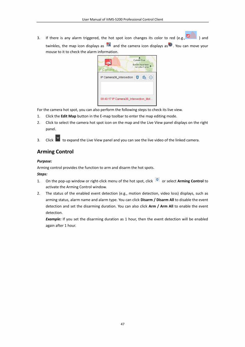
User Manual of iVMS-5200 Professional Control Client
47
3. If there is any alarm triggered, the hot spot icon changes its color to red (e.g., ) and
twinkles, the map icon displays as and the camera icon displays as . You can move your
mouse to it to check the alarm information.
For the camera hot spot, you can also perform the following steps to check its live view.
1. Click the Edit Map button in the E-map toolbar to enter the map editing mode.
2. Click to select the camera hot spot icon on the map and the Live View panel displays on the right
panel.
3. Click to expand the Live View panel and you can see the live video of the linked camera.
Arming Control
Purpose:
Arming control provides the function to arm and disarm the hot spots.
Steps:
1. On the pop-up window or right-click menu of the hot spot, click or select Arming Control to
activate the Arming Control window.
2. The status of the enabled event detection (e.g., motion detection, video loss) displays, such as
arming status, alarm name and alarm type. You can click Disarm / Disarm All to disable the event
detection and set the disarming duration. You can also click Arm / Arm All to enable the event
detection.
Example: If you set the disarming duration as 1 hour, then the event detection will be enabled
again after 1 hour.
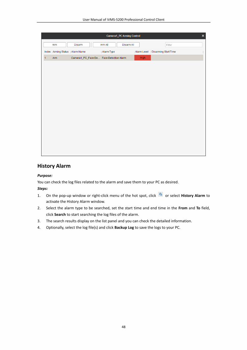
User Manual of iVMS-5200 Professional Control Client
48
History Alarm
Purpose:
You can check the log files related to the alarm and save them to your PC as desired.
Steps:
1. On the pop-up window or right-click menu of the hot spot, click or select History Alarm to
activate the History Alarm window.
2. Select the alarm type to be searched, set the start time and end time in the From and To field,
click Search to start searching the log files of the alarm.
3. The search results display on the list panel and you can check the detailed information.
4. Optionally, select the log file(s) and click Backup Log to save the logs to your PC.

User Manual of iVMS-5200 Professional Control Client
49
5.3 Hot Region Function
Purpose:
The hot region function links a map to another map. When you add a map to another map as a hot
region, an icon of the link to the added map is shown on the main map. The added map is called child
map while the map to which you add the hot region is the parent map.
Note: A map can only be added as the hot region for one time.
5.3.1 Adding the Hot Regions
Before you start:
At least 2 maps have been added. Refer to Chapter 5.1 Adding an E-map for detailed configuration
about adding maps.
Steps:
1. Click the Edit Map button in the E-map toolbar to enter the map editing mode.
2. Select an added map as the parent map.
3. Click the icon in the toolbar to open the Add Hot Region dialog box.
4. Check the checkbox (es) to select the child map(s) to be linked.
5. Optionally, you can edit the hot region name, select the hot region icon, choose the hot region
name color, and add description to the hot region. You can also click Icon Management to upload
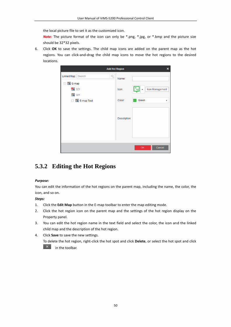
User Manual of iVMS-5200 Professional Control Client
50
the local picture file to set it as the customized icon.
Note: The picture format of the icon can only be *.png, *.jpg, or *.bmp and the picture size
should be 32*32 pixels.
6. Click OK to save the settings. The child map icons are added on the parent map as the hot
regions. You can click-and-drag the child map icons to move the hot regions to the desired
locations.
5.3.2 Editing the Hot Regions
Purpose:
You can edit the information of the hot regions on the parent map, including the name, the color, the
icon, and so on.
Steps:
1. Click the Edit Map button in the E-map toolbar to enter the map editing mode.
2. Click the hot region icon on the parent map and the settings of the hot region display on the
Property panel.
3. You can edit the hot region name in the text field and select the color, the icon and the linked
child map and the description of the hot region.
4. Click Save to save the new settings.
To delete the hot region, right-click the hot spot and click Delete, or select the hot spot and click
in the toolbar.
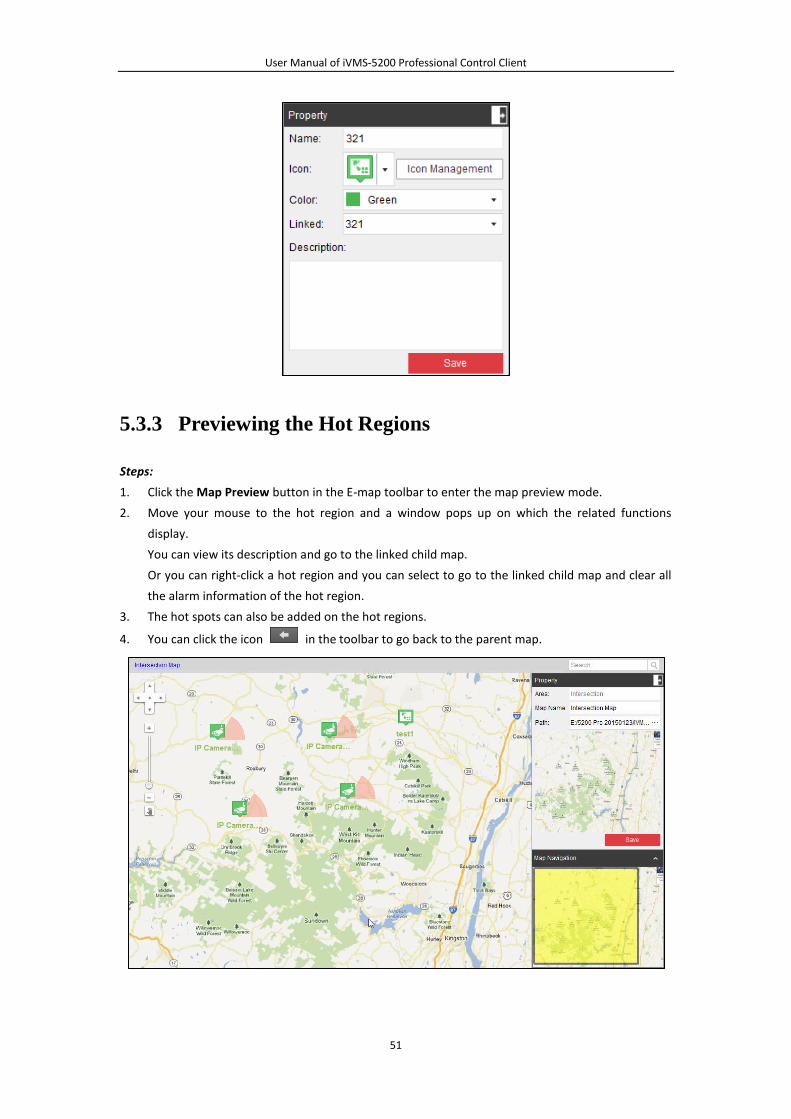
User Manual of iVMS-5200 Professional Control Client
51
5.3.3 Previewing the Hot Regions
Steps:
1. Click the Map Preview button in the E-map toolbar to enter the map preview mode.
2. Move your mouse to the hot region and a window pops up on which the related functions
display.
You can view its description and go to the linked child map.
Or you can right-click a hot region and you can select to go to the linked child map and clear all
the alarm information of the hot region.
3. The hot spots can also be added on the hot regions.
4. You can click the icon in the toolbar to go back to the parent map.
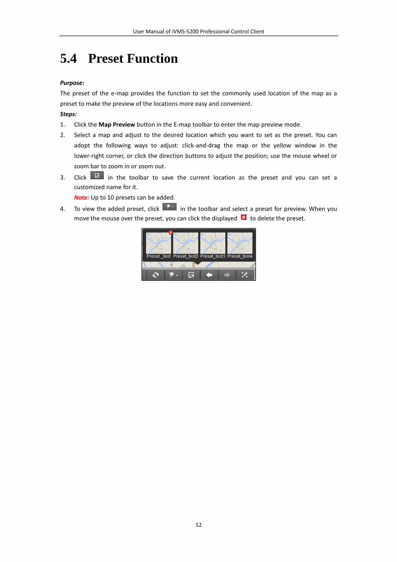
User Manual of iVMS-5200 Professional Control Client
52
5.4 Preset Function
Purpose:
The preset of the e-map provides the function to set the commonly used location of the map as a
preset to make the preview of the locations more easy and convenient.
Steps:
1. Click the Map Preview button in the E-map toolbar to enter the map preview mode.
2. Select a map and adjust to the desired location which you want to set as the preset. You can
adopt the following ways to adjust: click-and-drag the map or the yellow window in the
lower-right corner, or click the direction buttons to adjust the position; use the mouse wheel or
zoom bar to zoom in or zoom out.
3. Click in the toolbar to save the current location as the preset and you can set a
customized name for it.
Note: Up to 10 presets can be added.
4. To view the added preset, click in the toolbar and select a preset for preview. When you
move the mouse over the preset, you can click the displayed to delete the preset.

User Manual of iVMS-5200 Professional Control Client
53
Chapter 6 Business Intelligence
Purpose:
With the business intelligence (hereafter simplified as BI) function, you can transform the raw data
into useful information for business analysis purposes, such as displaying the total number of every
cashier's transaction volume to know the cashier's performance.
Before you start:
An area which contains POS terminal should be added to the iVMS-5200 Pro.
Note: For the area management, please refer to the User Manual of iVMS-5200 Pro Web Client.
Click the icon on the control panel,
or click View->Business Intelligence to open the Business Intelligence page.
Adding the Reports
Steps:
1. Open the BI page.
2. Click to pop up the Add Report window. You can select to add different kinds of reports.
Following reports are available:
Transaction Report: Display the total number of every cashier's transaction volume during a
period of time, to reflect the performance of the cashier.
Commodity Sales Volume: Calculate the sales volume of the selected commodities to help
the manager make sales decision.
Top Selling: To know the best-selling and bottom selling, thus manager can rearrange the
goods storage.
Traffic Distribution: Provide a report on the total traffic volume of every store during a
period of time, to know which store has the least traffic and then take action to get a better
performance.
Traffic Trending: Predict the afterward traffic flow according historic traffic data.
Customer Gender Analysis: To have a vivid view of in which gender group the product is
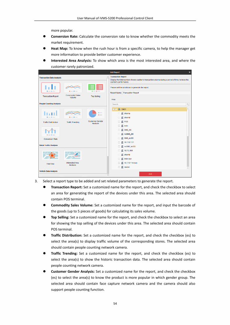
User Manual of iVMS-5200 Professional Control Client
54
more popular.
Conversion Rate: Calculate the conversion rate to know whether the commodity meets the
market requirement.
Heat Map: To know when the rush hour is from a specific camera, to help the manager get
more information to provide better customer experience.
Interested Area Analysis: To show which area is the most interested area, and where the
customer rarely patronized.
3. Select a report type to be added and set related parameters to generate the report.
Transaction Report: Set a customized name for the report, and check the checkbox to select
an area for generating the report of the devices under this area. The selected area should
contain POS terminal.
Commodity Sales Volume: Set a customized name for the report, and input the barcode of
the goods (up to 5 pieces of goods) for calculating its sales volume.
Top Selling: Set a customized name for the report, and check the checkbox to select an area
for showing the top selling of the devices under this area. The selected area should contain
POS terminal.
Traffic Distribution: Set a customized name for the report, and check the checkbox (es) to
select the area(s) to display traffic volume of the corresponding stores. The selected area
should contain people counting network camera.
Traffic Trending: Set a customized name for the report, and check the checkbox (es) to
select the area(s) to show the historic transaction data. The selected area should contain
people counting network camera.
Customer Gender Analysis: Set a customized name for the report, and check the checkbox
(es) to select the area(s) to know the product is more popular in which gender group. The
selected area should contain face capture network camera and the camera should also
support people counting function.
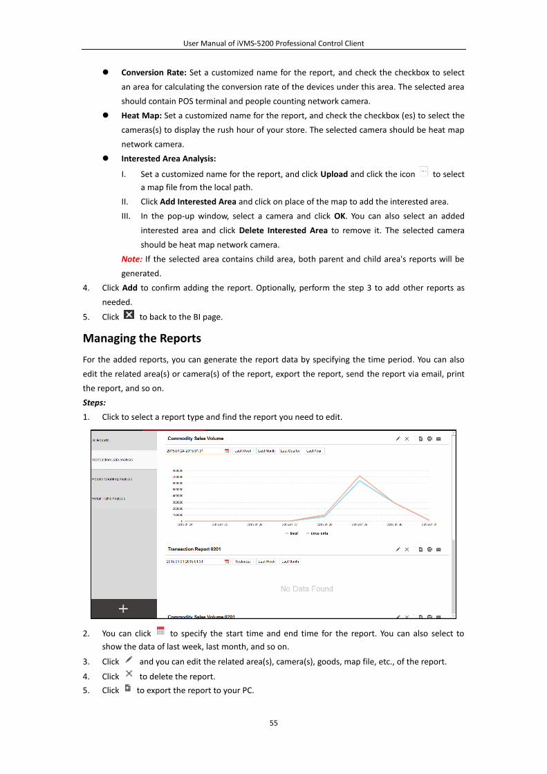
User Manual of iVMS-5200 Professional Control Client
55
Conversion Rate: Set a customized name for the report, and check the checkbox to select
an area for calculating the conversion rate of the devices under this area. The selected area
should contain POS terminal and people counting network camera.
Heat Map: Set a customized name for the report, and check the checkbox (es) to select the
cameras(s) to display the rush hour of your store. The selected camera should be heat map
network camera.
Interested Area Analysis:
I. Set a customized name for the report, and click Upload and click the icon to select
a map file from the local path.
II. Click Add Interested Area and click on place of the map to add the interested area.
III. In the pop-up window, select a camera and click OK. You can also select an added
interested area and click Delete Interested Area to remove it. The selected camera
should be heat map network camera.
Note: If the selected area contains child area, both parent and child area's reports will be
generated.
4. Click Add to confirm adding the report. Optionally, perform the step 3 to add other reports as
needed.
5. Click to back to the BI page.
Managing the Reports
For the added reports, you can generate the report data by specifying the time period. You can also
edit the related area(s) or camera(s) of the report, export the report, send the report via email, print
the report, and so on.
Steps:
1. Click to select a report type and find the report you need to edit.
2. You can click to specify the start time and end time for the report. You can also select to
show the data of last week, last month, and so on.
3. Click and you can edit the related area(s), camera(s), goods, map file, etc., of the report.
4. Click to delete the report.
5. Click to export the report to your PC.

User Manual of iVMS-5200 Professional Control Client
56
6. Click to print the report by the printer connected via the network
7. Click to send the report via email.
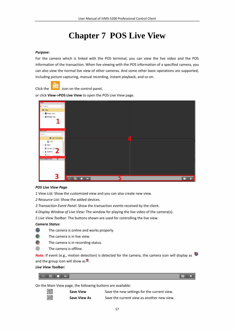
User Manual of iVMS-5200 Professional Control Client
57
Chapter 7 POS Live View
Purpose:
For the camera which is linked with the POS terminal, you can view the live video and the POS
information of the transaction. When live viewing with the POS information of a specified camera, you
can also view the normal live view of other cameras. And some other basic operations are supported,
including picture capturing, manual recording, instant playback, and so on.
Click the icon on the control panel,
or click View->POS Live View to open the POS Live View page.
POS Live View Page
1 View List: Show the customized view and you can also create new view.
2 Resource List: Show the added devices.
3 Transaction Event Panel: Show the transaction events received by the client.
4 Display Window of Live View: The window for playing the live video of the camera(s).
5 Live View Toolbar: The buttons shown are used for controlling the live view.
Camera Status:
The camera is online and works properly.
The camera is in live view.
The camera is in recording status.
The camera is offline.
Note: If event (e.g., motion detection) is detected for the camera, the camera icon will display as
and the group icon will show as .
Live View Toolbar:
On the Main View page, the following buttons are available:
Save View Save the new settings for the current view.
Save View As Save the current view as another new view.
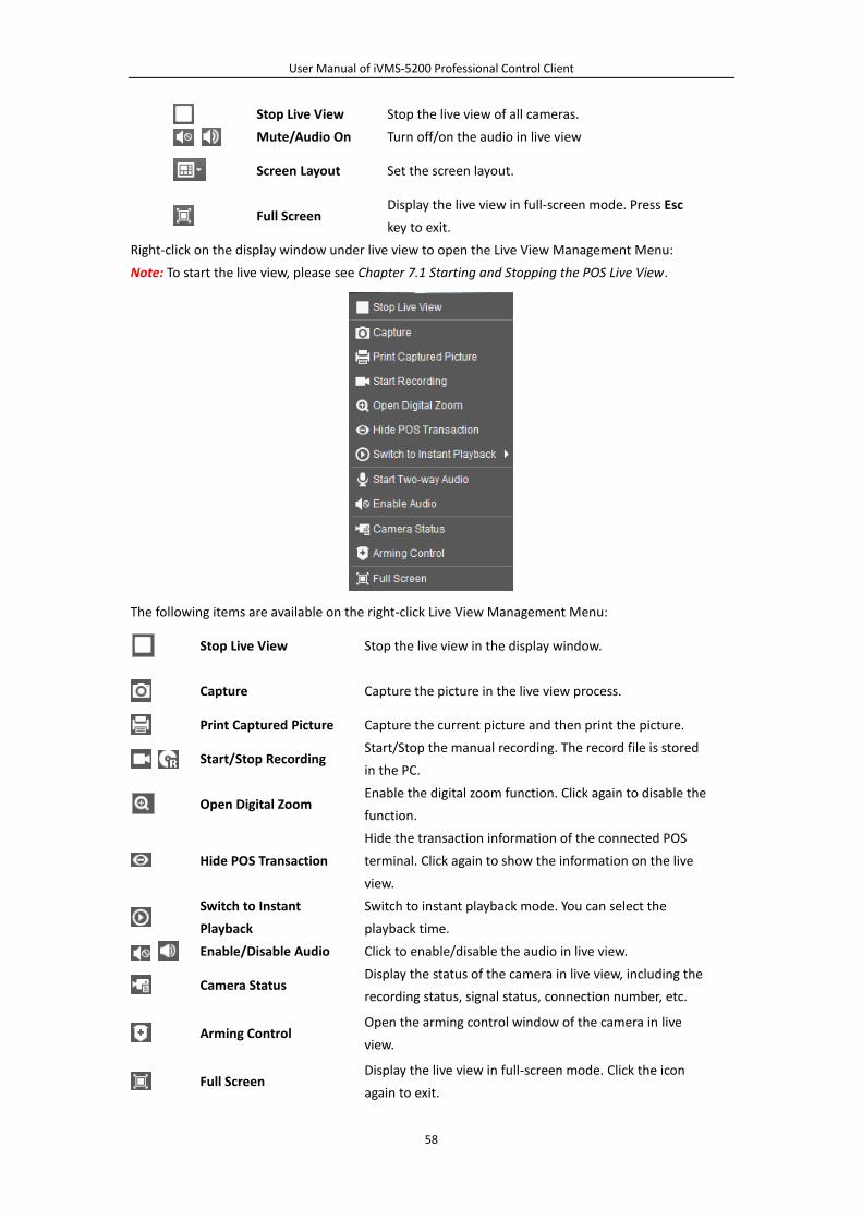
User Manual of iVMS-5200 Professional Control Client
58
Stop Live View Stop the live view of all cameras.
Mute/Audio On Turn off/on the audio in live view
Screen Layout Set the screen layout.
Full Screen Display the live view in full-screen mode. Press Esc
key to exit.
Right-click on the display window under live view to open the Live View Management Menu:
Note: To start the live view, please see Chapter 7.1 Starting and Stopping the POS Live View.
The following items are available on the right-click Live View Management Menu:
Stop Live View Stop the live view in the display window.
Capture Capture the picture in the live view process.
Print Captured Picture Capture the current picture and then print the picture.
Start/Stop Recording Start/Stop the manual recording. The record file is stored
in the PC.
Open Digital Zoom Enable the digital zoom function. Click again to disable the
function.
Hide POS Transaction
Hide the transaction information of the connected POS
terminal. Click again to show the information on the live
view.
Switch to Instant
Playback
Switch to instant playback mode. You can select the
playback time.
Enable/Disable Audio Click to enable/disable the audio in live view.
Camera Status Display the status of the camera in live view, including the
recording status, signal status, connection number, etc.
Arming Control Open the arming control window of the camera in live
view.
Full Screen Display the live view in full-screen mode. Click the icon
again to exit.
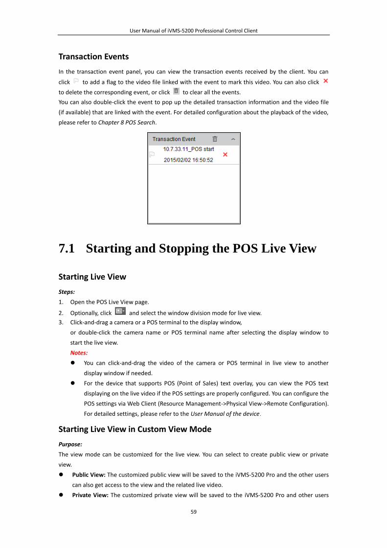
User Manual of iVMS-5200 Professional Control Client
59
Transaction Events
In the transaction event panel, you can view the transaction events received by the client. You can
click to add a flag to the video file linked with the event to mark this video. You can also click
to delete the corresponding event, or click to clear all the events.
You can also double-click the event to pop up the detailed transaction information and the video file
(if available) that are linked with the event. For detailed configuration about the playback of the video,
please refer to Chapter 8 POS Search.
7.1 Starting and Stopping the POS Live View
Starting Live View
Steps:
1. Open the POS Live View page.
2. Optionally, click and select the window division mode for live view.
3. Click-and-drag a camera or a POS terminal to the display window,
or double-click the camera name or POS terminal name after selecting the display window to
start the live view.
Notes:
You can click-and-drag the video of the camera or POS terminal in live view to another
display window if needed.
For the device that supports POS (Point of Sales) text overlay, you can view the POS text
displaying on the live video if the POS settings are properly configured. You can configure the
POS settings via Web Client (Resource Management->Physical View->Remote Configuration).
For detailed settings, please refer to the User Manual of the device
Starting Live View in Custom View Mode
Purpose:
The view mode can be customized for the live view. You can select to create public view or private
view.
Public View: The customized public view will be saved to the iVMS-5200 Pro and the other users
can also get access to the view and the related live video.
Private View: The customized private view will be saved to the iVMS-5200 Pro and other users
User Manual of iVMS-5200 Professional Control Client
60
who have the corresponding permission can also get access to the view and the related live
video.
Steps:
1. Open the POS Live View page.
2. In the view panel, click the icon to activate the view adding dialog box.
3. Input the view name and select the view type according to actual needs.
4. Click Add. The new view is of 4-Screen mode by default.
5. Optionally, click the icon in live view toolbar and select the window division mode for the
new view and click to save the window division mode for the new view.
6. Click-and-drag the camera or POS terminal to the display window,
or double-click the camera name or POS terminal name after selecting the display window to
start the live view.
7. Click the icon to save the new view. Optionally, you can click to save the current view
as another view.
After successfully settings the view, you can click to call the view.
Move the mouse onto the custom view, the following icons are available:
Edit View Name Edit the name of the custom view.
Delete View Delete the custom view.
Instant Playback
Start the instant playback of the cameras related to the
view. Up to 16 cameras can be switch to instant playback at
the same time.
Stopping the Live View
Steps:
1. Select the display window.
2. Click the icon that appears in the upper-right corner when the mouse pointer is over the
display window, or click Stop Live View on the right-click menu to stop the live view of the
display window. You can also click the button in live view toolbar to stop all the live view.
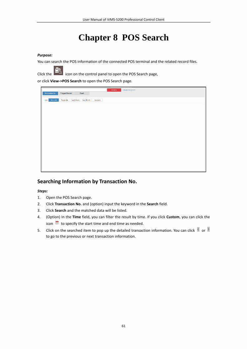
User Manual of iVMS-5200 Professional Control Client
61
Chapter 8 POS Search
Purpose:
You can search the POS information of the connected POS terminal and the related record files.
Click the icon on the control panel to open the POS Search page,
or click View->POS Search to open the POS Search page.
Searching Information by Transaction No.
Steps:
1. Open the POS Search page.
2. Click Transaction No. and (option) input the keyword in the Search field.
3. Click Search and the matched data will be listed.
4. (Option) In the Time field, you can filter the result by time. If you click Custom, you can click the
icon to specify the start time and end time as needed.
5. Click on the searched item to pop up the detailed transaction information. You can click or
to go to the previous or next transaction information.
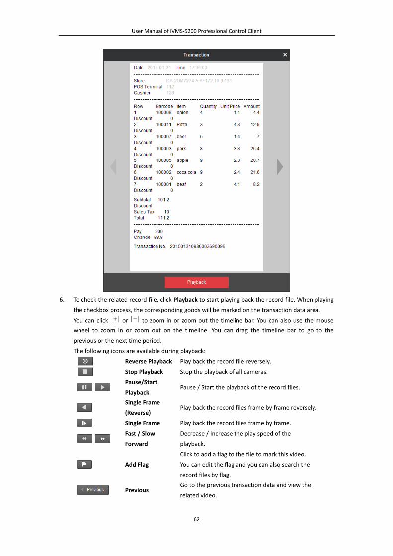
User Manual of iVMS-5200 Professional Control Client
62
6. To check the related record file, click Playback to start playing back the record file. When playing
the checkbox process, the corresponding goods will be marked on the transaction data area.
You can click or to zoom in or zoom out the timeline bar. You can also use the mouse
wheel to zoom in or zoom out on the timeline. You can drag the timeline bar to go to the
previous or the next time period.
The following icons are available during playback:
Reverse Playback Play back the record file reversely.
Stop Playback Stop the playback of all cameras.
Pause/Start
Playback Pause / Start the playback of the record files.
Single Frame
(Reverse) Play back the record files frame by frame reversely.
Single Frame Play back the record files frame by frame.
Fast / Slow
Forward
Decrease / Increase the play speed of the
playback.
Add Flag
Click to add a flag to the file to mark this video.
You can edit the flag and you can also search the
record files by flag.
Previous Go to the previous transaction data and view the
related video.
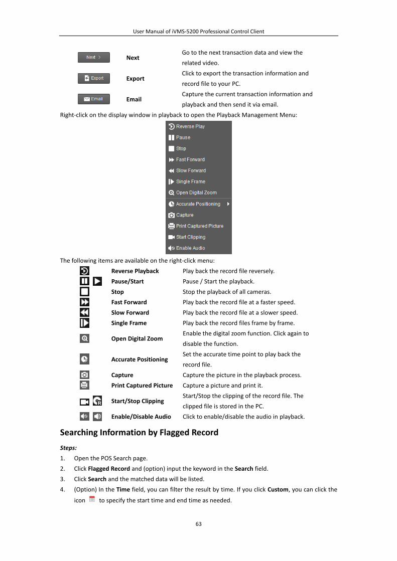
User Manual of iVMS-5200 Professional Control Client
63
Next Go to the next transaction data and view the
related video.
Export Click to export the transaction information and
record file to your PC.
Email Capture the current transaction information and
playback and then send it via email.
Right-click on the display window in playback to open the Playback Management Menu:
The following items are available on the right-click menu:
Reverse Playback Play back the record file reversely.
Pause/Start Pause / Start the playback.
Stop Stop the playback of all cameras.
Fast Forward Play back the record file at a faster speed.
Slow Forward Play back the record file at a slower speed.
Single Frame Play back the record files frame by frame.
Open Digital Zoom Enable the digital zoom function. Click again to
disable the function.
Accurate Positioning Set the accurate time point to play back the
record file.
Capture Capture the picture in the playback process.
Print Captured Picture Capture a picture and print it.
Start/Stop Clipping Start/Stop the clipping of the record file. The
clipped file is stored in the PC.
Enable/Disable Audio Click to enable/disable the audio in playback.
Searching Information by Flagged Record
Steps:
1. Open the POS Search page.
2. Click Flagged Record and (option) input the keyword in the Search field.
3. Click Search and the matched data will be listed.
4. (Option) In the Time field, you can filter the result by time. If you click Custom, you can click the
icon to specify the start time and end time as needed.
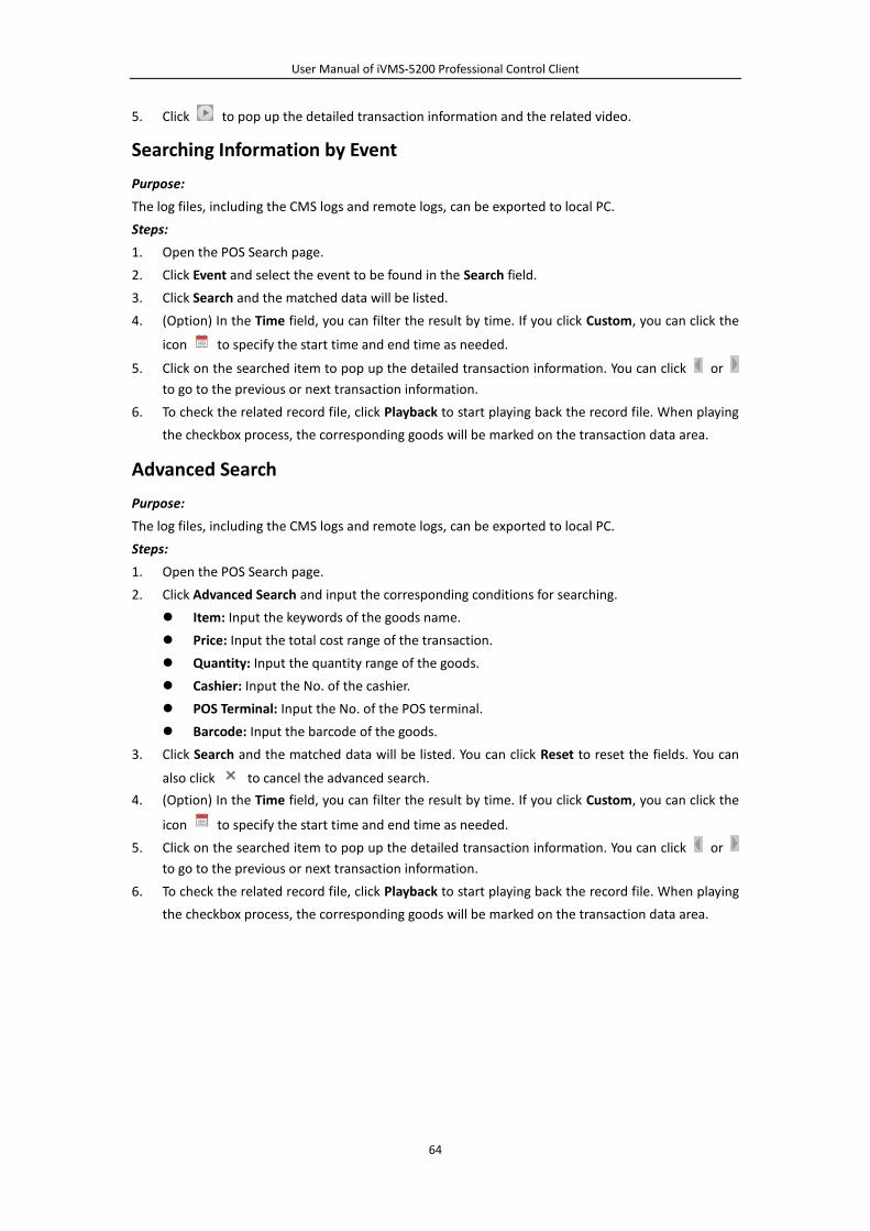
User Manual of iVMS-5200 Professional Control Client
64
5. Click to pop up the detailed transaction information and the related video.
Searching Information by Event
Purpose:
The log files, including the CMS logs and remote logs, can be exported to local PC.
Steps:
1. Open the POS Search page.
2. Click Event and select the event to be found in the Search field.
3. Click Search and the matched data will be listed.
4. (Option) In the Time field, you can filter the result by time. If you click Custom, you can click the
icon to specify the start time and end time as needed.
5. Click on the searched item to pop up the detailed transaction information. You can click or
to go to the previous or next transaction information.
6. To check the related record file, click Playback to start playing back the record file. When playing
the checkbox process, the corresponding goods will be marked on the transaction data area.
Advanced Search
Purpose:
The log files, including the CMS logs and remote logs, can be exported to local PC.
Steps:
1. Open the POS Search page.
2. Click Advanced Search and input the corresponding conditions for searching.
Item: Input the keywords of the goods name.
Price: Input the total cost range of the transaction.
Quantity: Input the quantity range of the goods.
Cashier: Input the No. of the cashier.
POS Terminal: Input the No. of the POS terminal.
Barcode: Input the barcode of the goods.
3. Click Search and the matched data will be listed. You can click Reset to reset the fields. You can
also click to cancel the advanced search.
4. (Option) In the Time field, you can filter the result by time. If you click Custom, you can click the
icon to specify the start time and end time as needed.
5. Click on the searched item to pop up the detailed transaction information. You can click or
to go to the previous or next transaction information.
6. To check the related record file, click Playback to start playing back the record file. When playing
the checkbox process, the corresponding goods will be marked on the transaction data area.
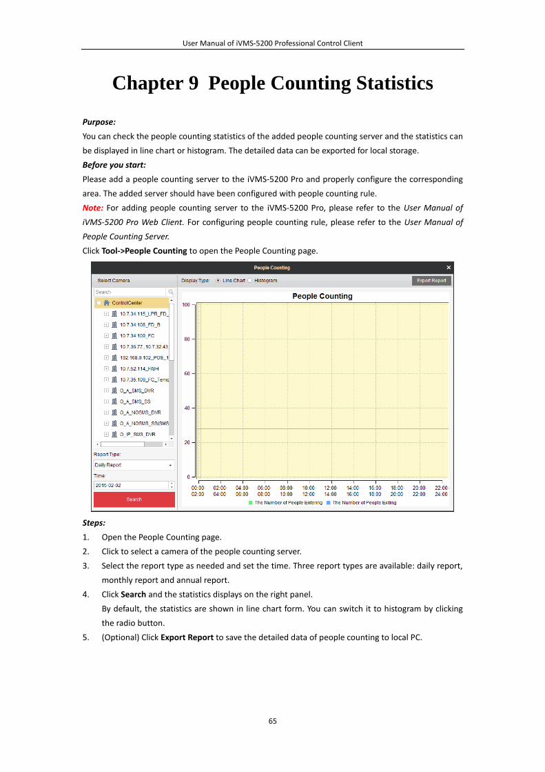
User Manual of iVMS-5200 Professional Control Client
65
Chapter 9 People Counting Statistics
Purpose:
You can check the people counting statistics of the added people counting server and the statistics can
be displayed in line chart or histogram. The detailed data can be exported for local storage.
Before you start:
Please add a people counting server to the iVMS-5200 Pro and properly configure the corresponding
area. The added server should have been configured with people counting rule.
Note: For adding people counting server to the iVMS-5200 Pro, please refer to the User Manual of
iVMS-5200 Pro Web Client. For configuring people counting rule, please refer to the User Manual of
People Counting Server.
Click Tool->People Counting to open the People Counting page.
Steps:
1. Open the People Counting page.
2. Click to select a camera of the people counting server.
3. Select the report type as needed and set the time. Three report types are available: daily report,
monthly report and annual report.
4. Click Search and the statistics displays on the right panel.
By default, the statistics are shown in line chart form. You can switch it to histogram by clicking
the radio button.
5. (Optional) Click Export Report to save the detailed data of people counting to local PC.

User Manual of iVMS-5200 Professional Control Client
66
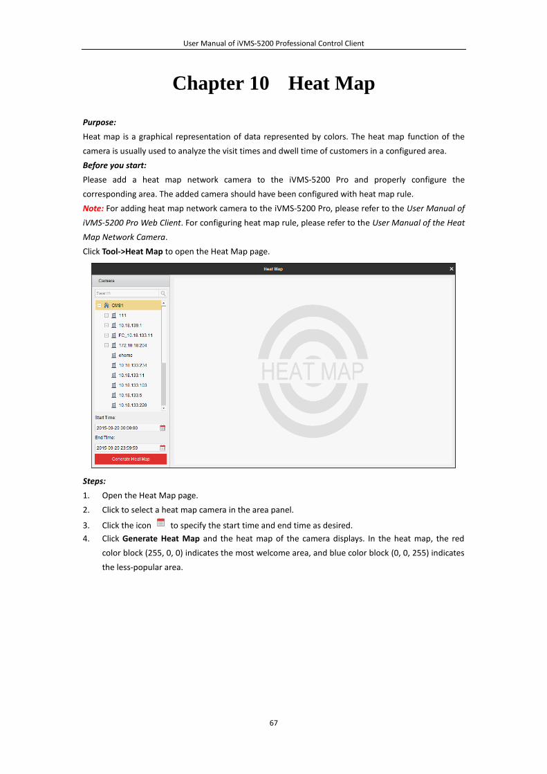
User Manual of iVMS-5200 Professional Control Client
67
Chapter 10 Heat Map
Purpose:
Heat map is a graphical representation of data represented by colors. The heat map function of the
camera is usually used to analyze the visit times and dwell time of customers in a configured area.
Before you start:
Please add a heat map network camera to the iVMS-5200 Pro and properly configure the
corresponding area. The added camera should have been configured with heat map rule.
Note: For adding heat map network camera to the iVMS-5200 Pro, please refer to the User Manual of
iVMS-5200 Pro Web Client. For configuring heat map rule, please refer to the User Manual of the Heat
Map Network Camera.
Click Tool->Heat Map to open the Heat Map page.
Steps:
1. Open the Heat Map page.
2. Click to select a heat map camera in the area panel.
3. Click the icon to specify the start time and end time as desired.
4. Click Generate Heat Map and the heat map of the camera displays. In the heat map, the red
color block (255, 0, 0) indicates the most welcome area, and blue color block (0, 0, 255) indicates
the less-popular area.
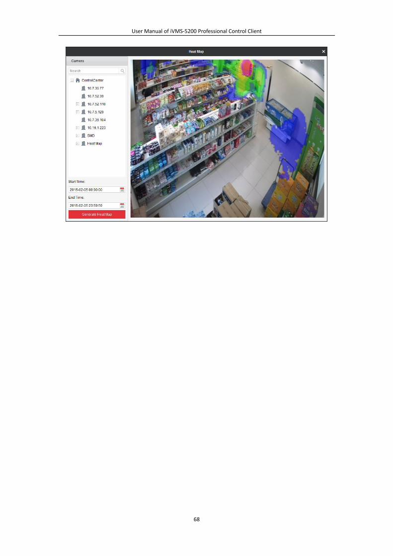
User Manual of iVMS-5200 Professional Control Client
68
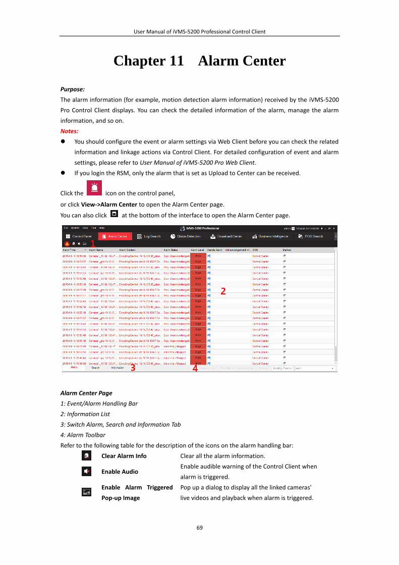
User Manual of iVMS-5200 Professional Control Client
69
Chapter 11 Alarm Center
Purpose:
The alarm information (for example, motion detection alarm information) received by the iVMS-5200
Pro Control Client displays. You can check the detailed information of the alarm, manage the alarm
information, and so on.
Notes:
You should configure the event or alarm settings via Web Client before you can check the related
information and linkage actions via Control Client. For detailed configuration of event and alarm
settings, please refer to User Manual of iVMS-5200 Pro Web Client.
If you login the RSM, only the alarm that is set as Upload to Center can be received.
Click the icon on the control panel,
or click View->Alarm Center to open the Alarm Center page.
You can also click at the bottom of the interface to open the Alarm Center page.
Alarm Center Page
1: Event/Alarm Handling Bar
2: Information List
3: Switch Alarm, Search and Information Tab
4: Alarm Toolbar
Refer to the following table for the description of the icons on the alarm handling bar:
Clear Alarm Info Clear all the alarm information.
Enable Audio Enable audible warning of the Control Client when
alarm is triggered.
Enable Alarm Triggered
Pop-up Image
Pop up a dialog to display all the linked cameras'
live videos and playback when alarm is triggered.
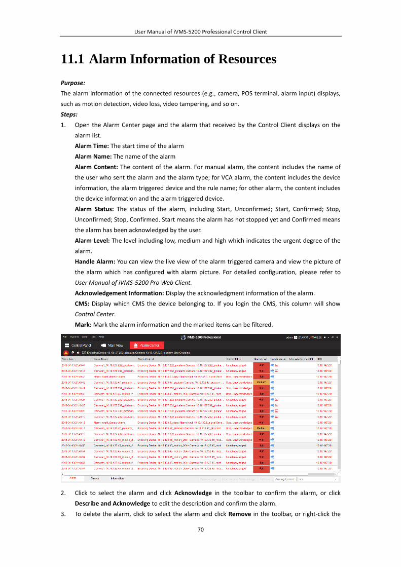
User Manual of iVMS-5200 Professional Control Client
70
11.1 Alarm Information of Resources
Purpose:
The alarm information of the connected resources (e.g., camera, POS terminal, alarm input) displays,
such as motion detection, video loss, video tampering, and so on.
Steps:
1. Open the Alarm Center page and the alarm that received by the Control Client displays on the
alarm list.
Alarm Time: The start time of the alarm
Alarm Name: The name of the alarm
Alarm Content: The content of the alarm. For manual alarm, the content includes the name of
the user who sent the alarm and the alarm type; for VCA alarm, the content includes the device
information, the alarm triggered device and the rule name; for other alarm, the content includes
the device information and the alarm triggered device.
Alarm Status: The status of the alarm, including Start, Unconfirmed; Start, Confirmed; Stop,
Unconfirmed; Stop, Confirmed. Start means the alarm has not stopped yet and Confirmed means
the alarm has been acknowledged by the user.
Alarm Level: The level including low, medium and high which indicates the urgent degree of the
alarm.
Handle Alarm: You can view the live view of the alarm triggered camera and view the picture of
the alarm which has configured with alarm picture. For detailed configuration, please refer to
User Manual of iVMS-5200 Pro Web Client.
Acknowledgement Information: Display the acknowledgment information of the alarm.
CMS: Display which CMS the device belonging to. If you login the CMS, this column will show
Control Center.
Mark: Mark the alarm information and the marked items can be filtered.
2. Click to select the alarm and click Acknowledge in the toolbar to confirm the alarm, or click
Describe and Acknowledge to edit the description and confirm the alarm.
3. To delete the alarm, click to select the alarm and click Remove in the toolbar, or right-click the
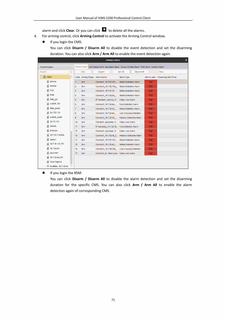
User Manual of iVMS-5200 Professional Control Client
71
alarm and click Clear. Or you can click to delete all the alarms.
4. For arming control, click Arming Control to activate the Arming Control window.
If you login the CMS:
You can click Disarm / Disarm All to disable the event detection and set the disarming
duration. You can also click Arm / Arm All to enable the event detection again.
If you login the RSM:
You can click Disarm / Disarm All to disable the alarm detection and set the disarming
duration for the specific CMS. You can also click Arm / Arm All to enable the alarm
detection again of corresponding CMS.
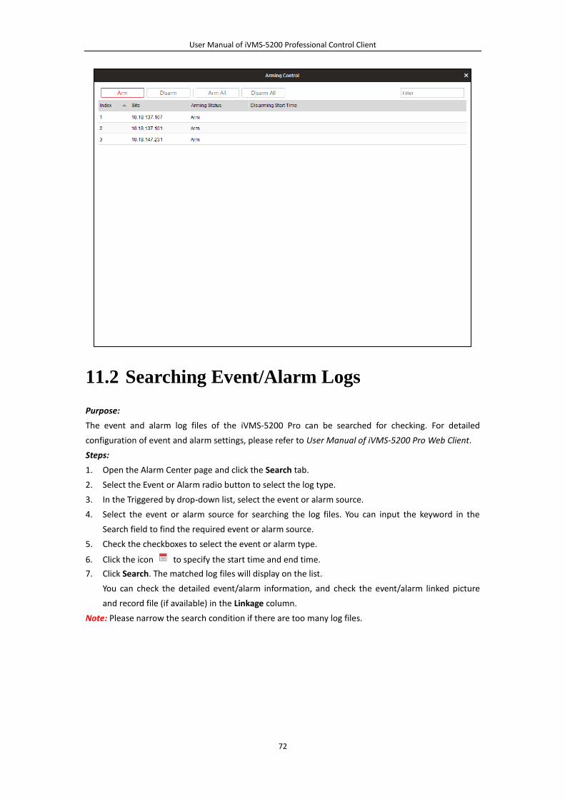
User Manual of iVMS-5200 Professional Control Client
72
11.2 Searching Event/Alarm Logs
Purpose:
The event and alarm log files of the iVMS-5200 Pro can be searched for checking. For detailed
configuration of event and alarm settings, please refer to User Manual of iVMS-5200 Pro Web Client.
Steps:
1. Open the Alarm Center page and click the Search tab.
2. Select the Event or Alarm radio button to select the log type.
3. In the Triggered by drop-down list, select the event or alarm source.
4. Select the event or alarm source for searching the log files. You can input the keyword in the
Search field to find the required event or alarm source.
5. Check the checkboxes to select the event or alarm type.
6. Click the icon to specify the start time and end time.
7. Click Search. The matched log files will display on the list.
You can check the detailed event/alarm information, and check the event/alarm linked picture
and record file (if available) in the Linkage column.
Note: Please narrow the search condition if there are too many log files.

User Manual of iVMS-5200 Professional Control Client
73
Backing up Log Files
Purpose:
The event/alarm log files can be exported to your PC.
Steps:
1. Search the needed log files.
2. Click Backup Log to open the Backup Log dialog box.
3. Click the icon and select a local saving path.
4. Optionally, you can also select an encoding format for the exported logs.
5. Click Backup to export the found log files.
11.3 Alarm Information of iVMS-5200 Pro
Purpose:
You can check the error and warning information during the operation of the iVMS-5200 Pro, such as
device connection failure, searching record files error, and so on.
Steps:
1. Open the Alarm Center page and click the Information tab.
2. You can check the details of the information. To delete the information, right-click the
information and click Clear, or click to delete all the information.
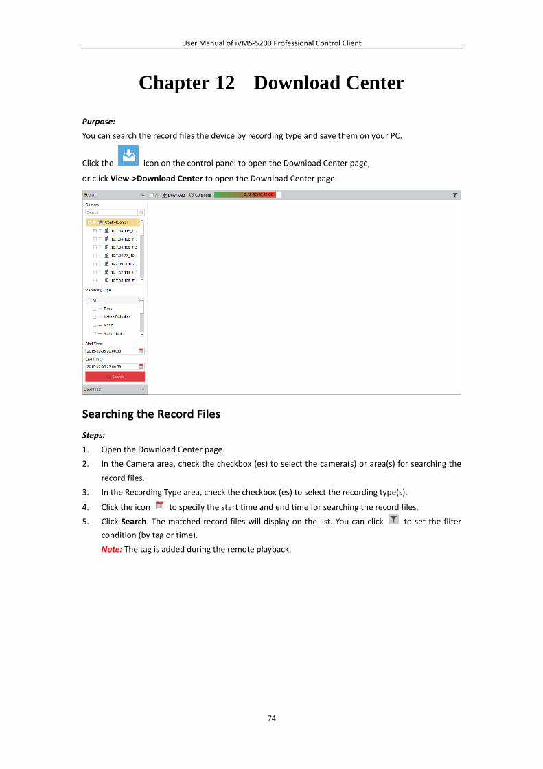
User Manual of iVMS-5200 Professional Control Client
74
Chapter 12 Download Center
Purpose:
You can search the record files the device by recording type and save them on your PC.
Click the icon on the control panel to open the Download Center page,
or click View->Download Center to open the Download Center page.
Searching the Record Files
Steps:
1. Open the Download Center page.
2. In the Camera area, check the checkbox (es) to select the camera(s) or area(s) for searching the
record files.
3. In the Recording Type area, check the checkbox (es) to select the recording type(s).
4. Click the icon to specify the start time and end time for searching the record files.
5. Click Search. The matched record files will display on the list. You can click to set the filter
condition (by tag or time).
Note: The tag is added during the remote playback.
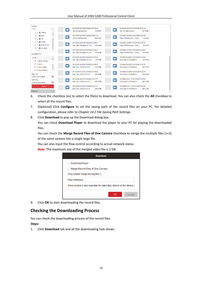
User Manual of iVMS-5200 Professional Control Client
75
6. Check the checkbox (es) to select the file(s) to download. You can also check the All checkbox to
select all the record files.
7. (Optional) Click Configure to set the saving path of the record files on your PC. For detailed
configuration, please refer to Chapter 14.2 File Saving Path Settings.
8. Click Download to pop up the Download dialog box.
You can check Download Player to download the player to your PC for playing the downloaded
files.
You can check the Merge Record Files of One Camera checkbox to merge the multiple files (>=2)
of the same camera into a single large file.
You can also input the flow control according to actual network status.
Note: The maximum size of the merged video file is 2 GB.
9. Click OK to start downloading the record files.
Checking the Downloading Process
You can check the downloading process of the record files.
Steps:
1. Click Download tab and all the downloading task shows.

User Manual of iVMS-5200 Professional Control Client
76
2. You can check the checkbox (es) to select the downloading item, and click Stop to stop the
downloading, click Start to resume the downloading, click Delete to remove the downloading
task (you can also select to delete the downloaded record files as well). For the downloaded
record files, you can click on the Player column to play it.
3. Click Downloading item, you can check the ongoing downloading tasks.
4. Click Done item, you can check the completed downloading tasks.
5. You can click Download Player to download the player to your PC for playing the downloaded
files.
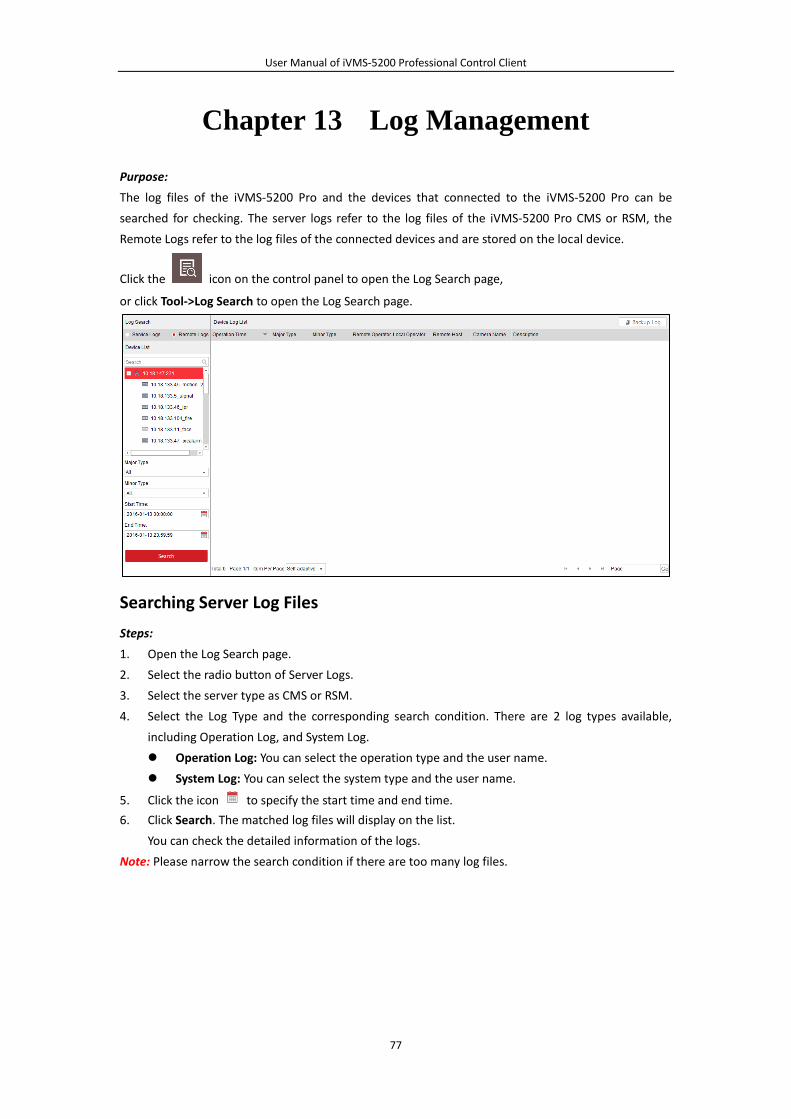
User Manual of iVMS-5200 Professional Control Client
77
Chapter 13 Log Management
Purpose:
The log files of the iVMS-5200 Pro and the devices that connected to the iVMS-5200 Pro can be
searched for checking. The server logs refer to the log files of the iVMS-5200 Pro CMS or RSM, the
Remote Logs refer to the log files of the connected devices and are stored on the local device.
Click the icon on the control panel to open the Log Search page,
or click Tool->Log Search to open the Log Search page.
Searching Server Log Files
Steps:
1. Open the Log Search page.
2. Select the radio button of Server Logs.
3. Select the server type as CMS or RSM.
4. Select the Log Type and the corresponding search condition. There are 2 log types available,
including Operation Log, and System Log.
Operation Log: You can select the operation type and the user name.
System Log: You can select the system type and the user name.
5. Click the icon to specify the start time and end time.
6. Click Search. The matched log files will display on the list.
You can check the detailed information of the logs.
Note: Please narrow the search condition if there are too many log files.
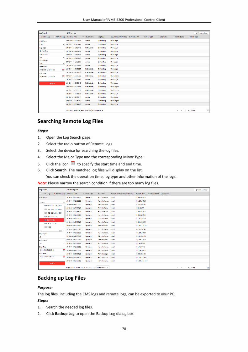
User Manual of iVMS-5200 Professional Control Client
78
Searching Remote Log Files
Steps:
1. Open the Log Search page.
2. Select the radio button of Remote Logs.
3. Select the device for searching the log files.
4. Select the Major Type and the corresponding Minor Type.
5. Click the icon to specify the start time and end time.
6. Click Search. The matched log files will display on the list.
You can check the operation time, log type and other information of the logs.
Note: Please narrow the search condition if there are too many log files.
Backing up Log Files
Purpose:
The log files, including the CMS logs and remote logs, can be exported to your PC.
Steps:
1. Search the needed log files.
2. Click Backup Log to open the Backup Log dialog box.

User Manual of iVMS-5200 Professional Control Client
79
3. Click the icon and select a local saving path.
4. Optionally, you can also select an encoding format for the exported logs.
5. Click Backup to export the found log files.
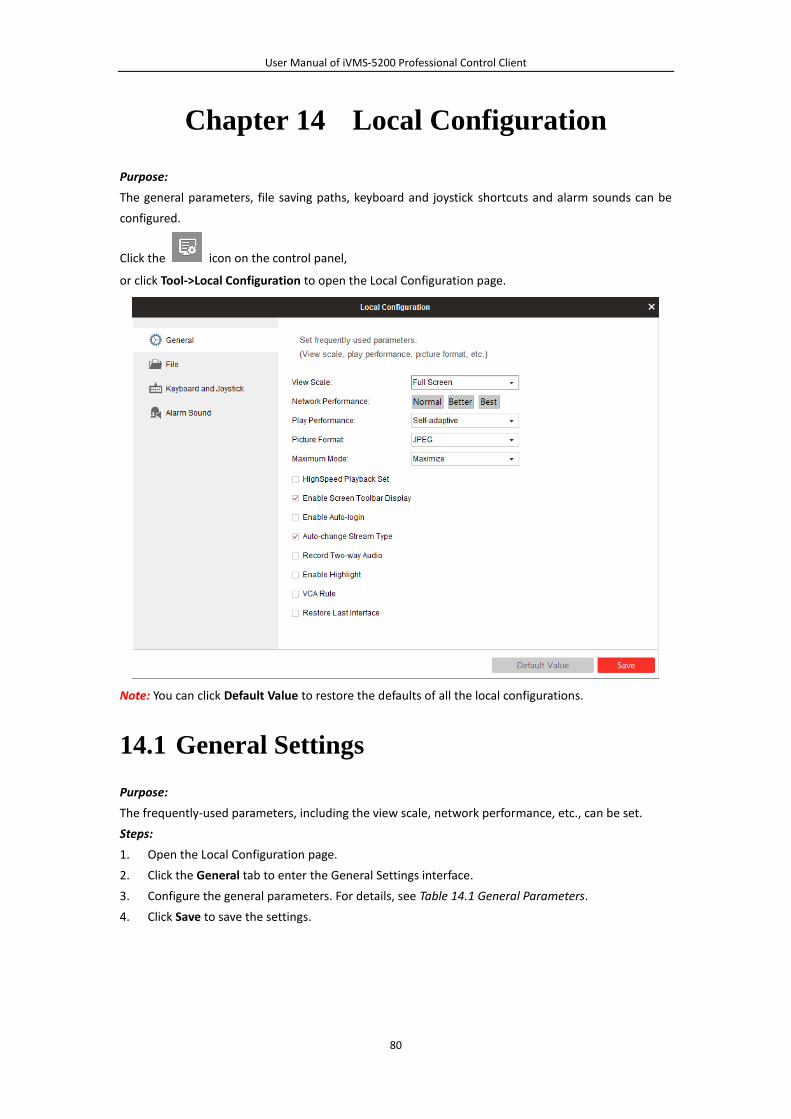
User Manual of iVMS-5200 Professional Control Client
80
Chapter 14 Local Configuration
Purpose:
The general parameters, file saving paths, keyboard and joystick shortcuts and alarm sounds can be
configured.
Click the icon on the control panel,
or click Tool->Local Configuration to open the Local Configuration page.
Note: You can click Default Value to restore the defaults of all the local configurations.
14.1 General Settings
Purpose:
The frequently-used parameters, including the view scale, network performance, etc., can be set.
Steps:
1. Open the Local Configuration page.
2. Click the General tab to enter the General Settings interface.
3. Configure the general parameters. For details, see Table 14.1 General Parameters.
4. Click Save to save the settings.
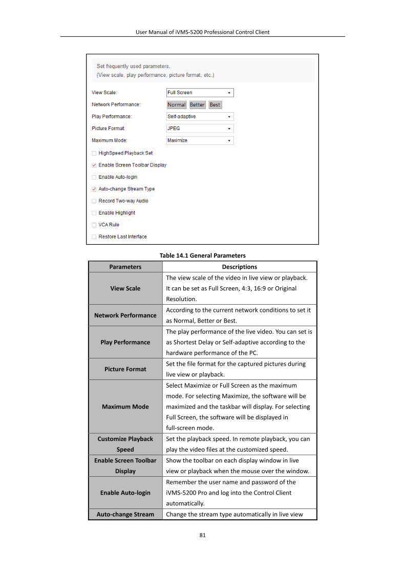
User Manual of iVMS-5200 Professional Control Client
81
Table 14.1 General Parameters
Parameters Descriptions
View Scale
The view scale of the video in live view or playback.
It can be set as Full Screen, 4:3, 16:9 or Original
Resolution.
Network Performance According to the current network conditions to set it
as Normal, Better or Best.
Play Performance
The play performance of the live video. You can set is
as Shortest Delay or Self-adaptive according to the
hardware performance of the PC.
Picture Format Set the file format for the captured pictures during
live view or playback.
Maximum Mode
Select Maximize or Full Screen as the maximum
mode. For selecting Maximize, the software will be
maximized and the taskbar will display. For selecting
Full Screen, the software will be displayed in
full-screen mode.
Customize Playback
Speed
Set the playback speed. In remote playback, you can
play the video files at the customized speed.
Enable Screen Toolbar
Display
Show the toolbar on each display window in live
view or playback when the mouse over the window.
Enable Auto-login
Remember the user name and password of the
iVMS-5200 Pro and log into the Control Client
automatically.
Auto-change Stream Change the stream type automatically in live view
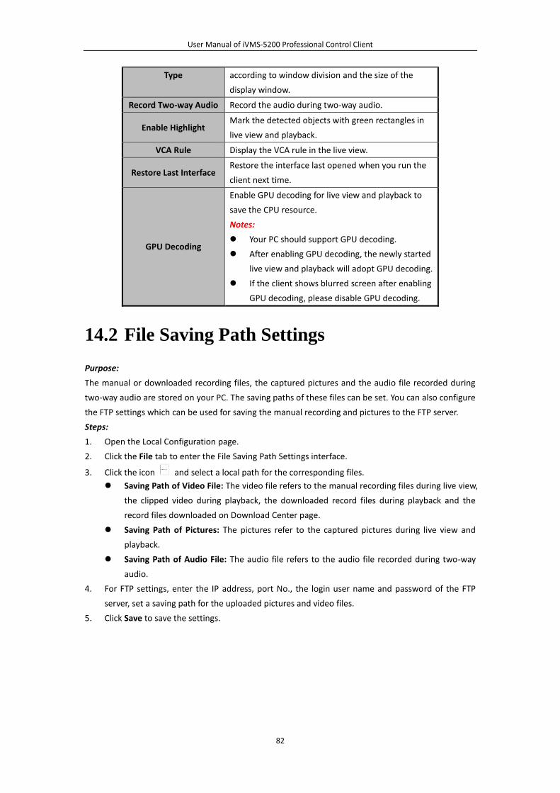
User Manual of iVMS-5200 Professional Control Client
82
Type according to window division and the size of the
display window.
Record Two-way Audio Record the audio during two-way audio.
Enable Highlight Mark the detected objects with green rectangles in
live view and playback.
VCA Rule Display the VCA rule in the live view.
Restore Last Interface Restore the interface last opened when you run the
client next time.
GPU Decoding
Enable GPU decoding for live view and playback to
save the CPU resource.
Notes:
Your PC should support GPU decoding.
After enabling GPU decoding, the newly started
live view and playback will adopt GPU decoding.
If the client shows blurred screen after enabling
GPU decoding, please disable GPU decoding.
14.2 File Saving Path Settings
Purpose:
The manual or downloaded recording files, the captured pictures and the audio file recorded during
two-way audio are stored on your PC. The saving paths of these files can be set. You can also configure
the FTP settings which can be used for saving the manual recording and pictures to the FTP server.
Steps:
1. Open the Local Configuration page.
2. Click the File tab to enter the File Saving Path Settings interface.
3. Click the icon and select a local path for the corresponding files.
Saving Path of Video File: The video file refers to the manual recording files during live view,
the clipped video during playback, the downloaded record files during playback and the
record files downloaded on Download Center page.
Saving Path of Pictures: The pictures refer to the captured pictures during live view and
playback.
Saving Path of Audio File: The audio file refers to the audio file recorded during two-way
audio.
4. For FTP settings, enter the IP address, port No., the login user name and password of the FTP
server, set a saving path for the uploaded pictures and video files.
5. Click Save to save the settings.

User Manual of iVMS-5200 Professional Control Client
83
14.3 Keyboard and Joystick Shortcuts Settings
Purpose:
DS-1003KI and DS-1004KI keyboard, PC keyboard, USB joystick and USB keyboard (DS-1005KI) can
provide some frequently used functions of the system. You can set the shortcuts for PC keyboard, USB
joystick and USB keyboard to get quick and convenient access to the commonly used actions.
Note: For detailed operation of connecting the DS-1003KI, DS-1004KI and DS-1005KI keyboard to PC
that runs Control Client, refer to the user manual of the corresponding keyboard.
Steps:
1. Open the Local Configuration page.
2. Click the Keyboard and Joystick tab to enter the Keyboard and Joystick Settings interface.
3. For keyboard: Select the COM port from the drop-down list if DS-1003KI or DS-1004KI keyboard
is connected to the PC installed with the Control Client.
4. For PC keyboard, USB joystick and USB keyboard:
I. Select a certain function from the list.
II. Double-click the item field under the PC Keyboard, USB Joystick or USB keyboard column.
III. Select the compound keys operation or number from the drop-down list to set it as the
shortcuts for the function of the PC keyboard, USB joystick or USB keyboard.
5. Click Save to save the settings.
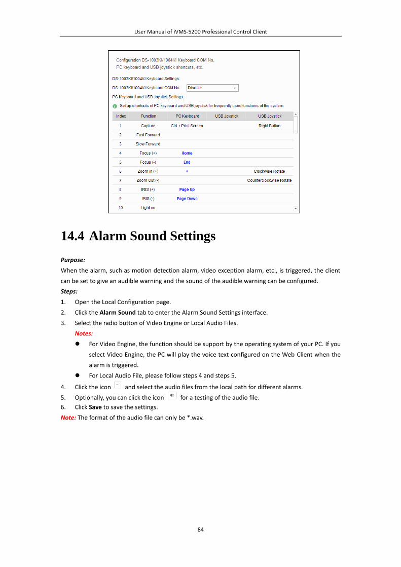
User Manual of iVMS-5200 Professional Control Client
84
14.4 Alarm Sound Settings
Purpose:
When the alarm, such as motion detection alarm, video exception alarm, etc., is triggered, the client
can be set to give an audible warning and the sound of the audible warning can be configured.
Steps:
1. Open the Local Configuration page.
2. Click the Alarm Sound tab to enter the Alarm Sound Settings interface.
3. Select the radio button of Video Engine or Local Audio Files.
Notes:
For Video Engine, the function should be support by the operating system of your PC. If you
select Video Engine, the PC will play the voice text configured on the Web Client when the
alarm is triggered.
For Local Audio File, please follow steps 4 and steps 5.
4. Click the icon and select the audio files from the local path for different alarms.
5. Optionally, you can click the icon for a testing of the audio file.
6. Click Save to save the settings.
Note: The format of the audio file can only be *.wav.
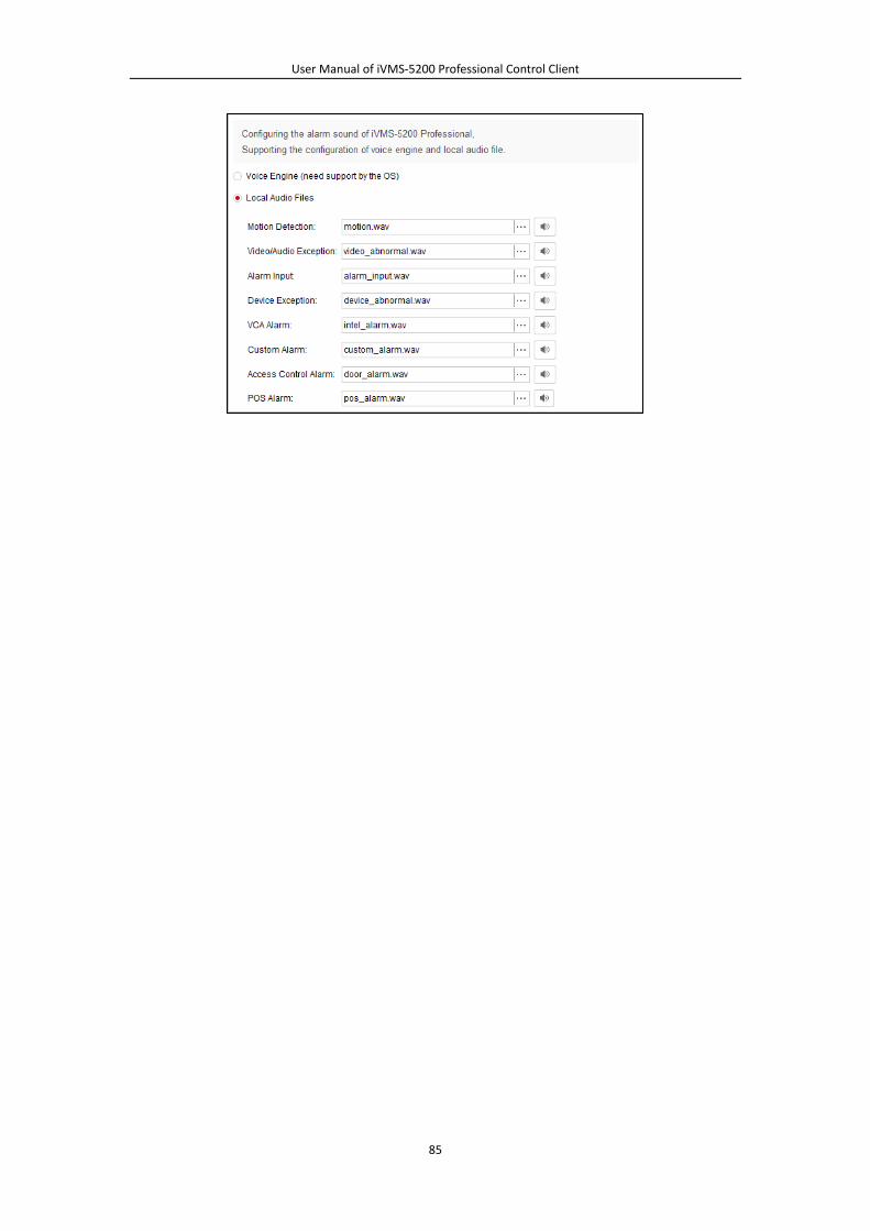
User Manual of iVMS-5200 Professional Control Client
85
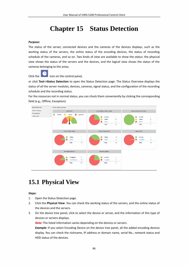
User Manual of iVMS-5200 Professional Control Client
86
Chapter 15 Status Detection
Purpose:
The status of the server, connected devices and the cameras of the devices displays, such as the
working status of the servers, the online status of the encoding devices, the status of recording
schedule of the cameras, and so on. Two kinds of view are available to show the status: the physical
view shows the status of the servers and the devices, and the logical view shows the status of the
cameras belonging to the areas.
Click the icon on the control panel,
or click Tool->Status Detection to open the Status Detection page. The Status Overview displays the
status of all the server modules, devices, cameras, signal status, and the configuration of the recording
schedule and the recording status.
For the resources not in normal status, you can check them conveniently by clicking the corresponding
field (e.g., Offline, Exception).
15.1 Physical View
Steps:
1. Open the Status Detection page.
2. Click the Physical View. You can check the working status of the servers, and the online status of
the devices and the servers.
3. On the device tree panel, click to select the device or server, and the information of this type of
devices or servers displays.
Note: The listed information varies depending on the devices or servers.
Example: If you select Encoding Device on the device tree panel, all the added encoding devices
display. You can check the nickname, IP address or domain name, serial No., network status and
HDD status of the devices.
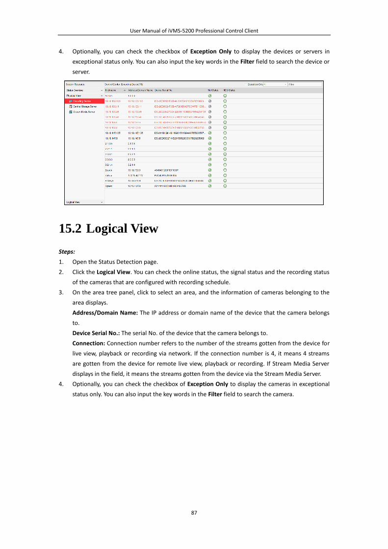
User Manual of iVMS-5200 Professional Control Client
87
4. Optionally, you can check the checkbox of Exception Only to display the devices or servers in
exceptional status only. You can also input the key words in the Filter field to search the device or
server.
15.2 Logical View
Steps:
1. Open the Status Detection page.
2. Click the Logical View. You can check the online status, the signal status and the recording status
of the cameras that are configured with recording schedule.
3. On the area tree panel, click to select an area, and the information of cameras belonging to the
area displays.
Address/Domain Name: The IP address or domain name of the device that the camera belongs
to.
Device Serial No.: The serial No. of the device that the camera belongs to.
Connection: Connection number refers to the number of the streams gotten from the device for
live view, playback or recording via network. If the connection number is 4, it means 4 streams
are gotten from the device for remote live view, playback or recording. If Stream Media Server
displays in the field, it means the streams gotten from the device via the Stream Media Server.
4. Optionally, you can check the checkbox of Exception Only to display the cameras in exceptional
status only. You can also input the key words in the Filter field to search the camera.
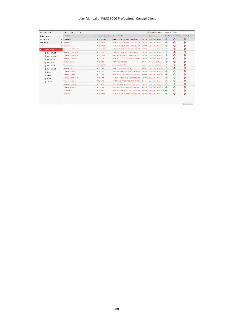
User Manual of iVMS-5200 Professional Control Client
88
User Manual of iVMS-5200 Professional Control Client
89