Embed Size (px)
Citation preview

GP-PWM-10
_________________________________________________________________________________
© 2015 Carmanah Technologies Corporation
User Manual

GP-PWM-10
_________________________________________________________________________________
2
© 2015 Carmanah Technologies Corporation

GP-PWM-10
_________________________________________________________________________________
3
© 2015 Carmanah Technologies Corporation
Contents 1.0 Installation Overview 4
1.1 Introduction 4 1.2 Specifications 5
2.0 Warnings 6
3.0 Tools and Materials Needed 6
4.0 Choosing a Location 7
5.0 Installation Instructions 7
6.0 Wiring Diagram 9
7.0 Operating Instructions 10
7.1 Power Up 10 7.2 Setting the Battery Charging Profile 10 7.3 Battery Charging Profile Chart 11 7.4 Maximum Power Boost Technology™ 12 7.5 Viewing the Controller Display Information 12 7.6 Errors 14
8.0 Display Symbols 15
9.0 USB Charging 16
10.0 Frequently Asked Questions (FAQs) 17
11.0 Troubleshooting Problems 18
11.1 Problems with the Display 18 11.2 Problems with Voltage 19 11.3 Problems with Current 20
12.0 Limited Warranty 22
12.1 Repair and Return Information 22

GP-PWM-10
_________________________________________________________________________________
4
© 2015 Carmanah Technologies Corporation
1.0 Installation Overview
1.1 Introduction
A Solar Controller (or Charge Controller / Regulator) is an essential component of your photovoltaic solar system. The Controller maintains the life of the battery by protecting it from overcharging. When your battery has reached a 100% state of charge, the Controller prevents overcharging by limiting the current flowing into the batteries from your solar array. The GP-PWM-10 is a 12-volt photovoltaic (PV) charge controller rated for a continuous solar current input of 10 amps. The GP-PWM-10 uses Pulse Width Modulation (PWM) technology and a unique four stage charging system that includes an optional equalize setting to charge and protect your battery bank. The GP-PWM-10 features an LCD digital display that shows the charge current of the solar array, system battery voltage and battery capacity. The GP-PWM-10 also features Maximum Power Boost Technology™ for manual bulk charge at any stage of the charge cycle.

GP-PWM-10
_________________________________________________________________________________
5
© 2015 Carmanah Technologies Corporation
1.2 Specifications
Description Value Dimensions
(H x W x D):
100 x 102 x 29 mm
3.94 x 4.02 x 1.14 in
Weight: 178 g / 6.3 oz
Maximum Wire Gauge:
#4 AWG
Warranty: 5 years
PWM Charging
3 Battery Charging
profiles
4 Stage Charging
Monthly Equalize
option
Displays Charging
Current, Battery
Voltage and Battery
State of Charge
Reverse Polarity
protected
Temperature
Compensated
RoHS Compliant,
environmentally safe
Accepts up to 160
watts of solar at 12
volts
Maximum Power Boost
Technology
Nominal System Voltage 12V
Max. Solar Array Current
10A (amperage is reduced above 50°C)
Battery Voltage Range 6V – 15.5V
Max. Solar Voltage 28V
Operating Consumption
(Display backlight on)
15mA
Operating Consumption
(Display backlight off)
6mA
Bulk/Absorption Voltage
(Sealed/Gel, AGM,
Flooded)
14.1/14.4/14.4V
(25°C / 77°F), 1 - 2h / Day
Float Voltage 13.7V (25°C / 77°F)
Equalization Voltage 14.9V (25°C / 77°F),
2h / 28 Day or V < 12.1
Temperature Compensation - 24mV/ºC / -13V/ºF
USB charger 5V, 800mA
Operating Temperature
Display Operating
Temperature
- 40 to 85°C / - 40 to 185°F
- 10 to 55°C / - 14 to 131°F
Humidity 99% N.C.
Protection Battery Reverse Polarity, Solar Array
Reverse Polarity, Over Temperature,
PV Short Circuit, Over Current
The total rated Maximum Power Current (Imp) of the PV input should not exceed 10 amps.
The GP-PWM-10 will limit PV current above 10 Amps. Although the GP-PWM-10 will accept PV
current greater than 10 Amps for a short duration, damage may occur if the GP-PWM-10 operates
continuously with greater than 10 Amps of PV input.
GP-PWM-10
_________________________________________________________________________________
6
© 2015 Carmanah Technologies Corporation
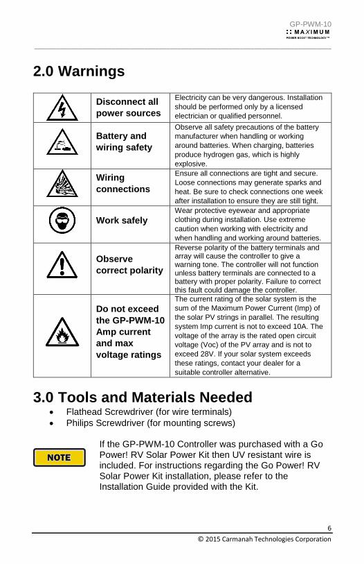
2.0 Warnings
Disconnect all
power sources
Electricity can be very dangerous. Installation
should be performed only by a licensed
electrician or qualified personnel.
Battery and
wiring safety
Observe all safety precautions of the battery
manufacturer when handling or working
around batteries. When charging, batteries
produce hydrogen gas, which is highly
explosive.
Wiring
connections
Ensure all connections are tight and secure.
Loose connections may generate sparks and
heat. Be sure to check connections one week
after installation to ensure they are still tight.
Work safely
Wear protective eyewear and appropriate
clothing during installation. Use extreme
caution when working with electricity and
when handling and working around batteries.
Observe
correct polarity
Reverse polarity of the battery terminals and array will cause the controller to give a warning tone. The controller will not function unless battery terminals are connected to a battery with proper polarity. Failure to correct this fault could damage the controller.
Do not exceed
the GP-PWM-10
Amp current
and max
voltage ratings
The current rating of the solar system is the
sum of the Maximum Power Current (Imp) of
the solar PV strings in parallel. The resulting
system Imp current is not to exceed 10A. The
voltage of the array is the rated open circuit
voltage (Voc) of the PV array and is not to
exceed 28V. If your solar system exceeds
these ratings, contact your dealer for a
suitable controller alternative.
3.0 Tools and Materials Needed Flathead Screwdriver (for wire terminals)
Philips Screwdriver (for mounting screws)
If the GP-PWM-10 Controller was purchased with a Go Power! RV Solar Power Kit then UV resistant wire is included. For instructions regarding the Go Power! RV Solar Power Kit installation, please refer to the Installation Guide provided with the Kit.

GP-PWM-10
_________________________________________________________________________________
7
© 2015 Carmanah Technologies Corporation
4.0 Choosing a Location
The GP-PWM-10 is designed to be mounted against a wall, out of the way but easily visible. The GP-PWM-10 should be:
Mounted as close to the battery as possible
Mounted on a vertical surface to optimize cooling of the unit
Indoors, protected from the weather In an RV, the most common controller location is above the refrigerator. The wire from the solar array most commonly enters the RV through the fridge vent on the roof or by using the Go Power! Cable Entry Plate (sold separately) that allows installers to run wires through any part of the roof. PV connections should connect directly to the controller. Positive and negative battery connections must connect directly from the controller to the batteries. Use of a positive or negative distribution bus is allowed between the controller and battery as long as it is properly sized, electrically safe and an adequate wire size is maintained.
5.0 Installation Instructions
1. Complete the installation of the solar modules. If this GP-PWM-10 was purchased as part of a Go Power! Solar Power Kit, follow the Installation Guide provided. Otherwise, follow manufacturer’s instructions for solar module mounting and wiring.
2. Select wire type and gauge. If this GP-PWM-10 was
purchased as part of a Go Power! Solar Power Kit, appropriate wire type, gauge and length is provided. Please continue to Section 6, “Operating Instructions.” If the GP-PWM-10 was purchased separately, follow the instructions included here.
Wire type is recommended to be a stranded copper UV resistant wire. Wire fatigue and the likelihood of a loose connection are greatly reduced in stranded wire compared to solid wire. Wire gauge should be able to sustain rated current and minimize voltage drop.
GP-PWM-10
_________________________________________________________________________________
8
© 2015 Carmanah Technologies Corporation
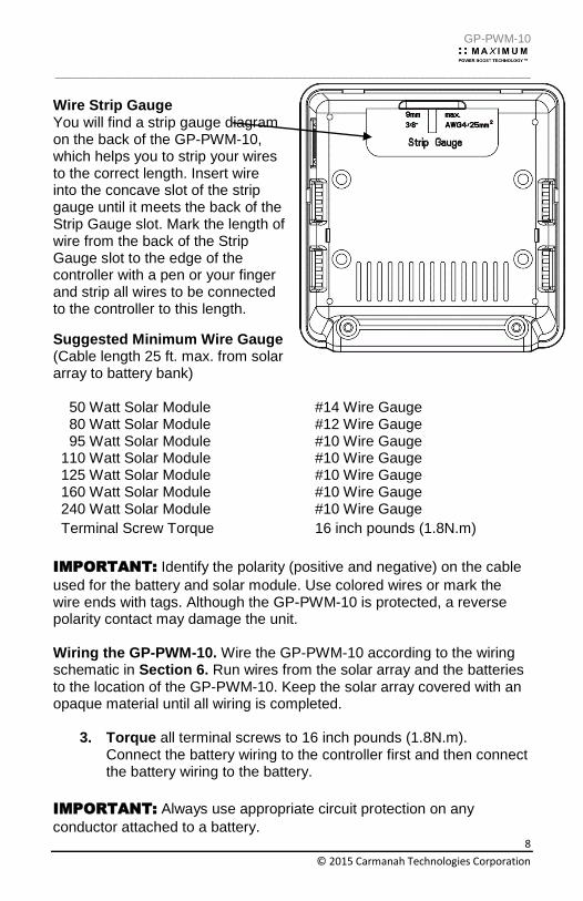
Wire Strip Gauge You will find a strip gauge diagram on the back of the GP-PWM-10, which helps you to strip your wires to the correct length. Insert wire into the concave slot of the strip gauge until it meets the back of the Strip Gauge slot. Mark the length of wire from the back of the Strip Gauge slot to the edge of the controller with a pen or your finger and strip all wires to be connected to the controller to this length.
Suggested Minimum Wire Gauge (Cable length 25 ft. max. from solar array to battery bank) 50 Watt Solar Module #14 Wire Gauge 80 Watt Solar Module #12 Wire Gauge 95 Watt Solar Module #10 Wire Gauge 110 Watt Solar Module #10 Wire Gauge 125 Watt Solar Module #10 Wire Gauge 160 Watt Solar Module #10 Wire Gauge 240 Watt Solar Module #10 Wire Gauge
Terminal Screw Torque 16 inch pounds (1.8N.m)
IMPORTANT: Identify the polarity (positive and negative) on the cable
used for the battery and solar module. Use colored wires or mark the wire ends with tags. Although the GP-PWM-10 is protected, a reverse polarity contact may damage the unit. Wiring the GP-PWM-10. Wire the GP-PWM-10 according to the wiring schematic in Section 6. Run wires from the solar array and the batteries to the location of the GP-PWM-10. Keep the solar array covered with an opaque material until all wiring is completed.
3. Torque all terminal screws to 16 inch pounds (1.8N.m). Connect the battery wiring to the controller first and then connect the battery wiring to the battery.
IMPORTANT: Always use appropriate circuit protection on any
conductor attached to a battery.
GP-PWM-10
_________________________________________________________________________________
9
© 2015 Carmanah Technologies Corporation
With battery power attached, the controller should power up and display information. Connect the solar wiring to the controller and remove the opaque material from the solar array. The negative solar array and battery wiring must be connected directly to the controller for proper operation. Do not connect the negative solar array or negative battery controller wiring to the chassis of the vehicle.
4. Mounting the GP-PWM-10. Mount the GP-PWM-10 to the wall
using the included four mounting screws.
IMPORTANT: You must set the battery type on the GP-PWM-10
before you begin to use the controller (follow steps in Section 7). The default battery setting is for AGM batteries.
Congratulations, your GP-PWM-10 should now be operational. If the battery power is low and the solar array is producing power, your battery should begin to charge.
5. Re-torque: After 30 days of operation, re-torque all terminal
screws to ensure the wires are properly secured to the controller.
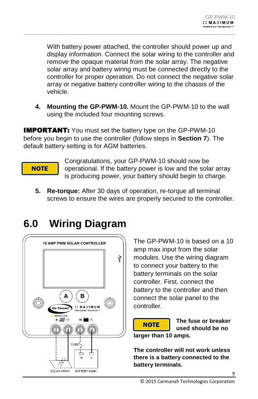
6.0 Wiring Diagram
The GP-PWM-10 is based on a 10
amp max input from the solar
modules. Use the wiring diagram
to connect your battery to the
battery terminals on the solar
controller. First, connect the
battery to the controller and then
connect the solar panel to the
controller.
The fuse or breaker
used should be no
larger than 10 amps.
The controller will not work unless
there is a battery connected to the
battery terminals.
GP-PWM-10
_________________________________________________________________________________
10
© 2015 Carmanah Technologies Corporation
7.0 Operating Instructions
7.1 Power Up
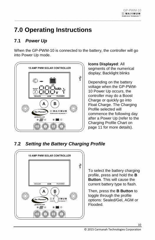
When the GP-PWM-10 is connected to the battery, the controller will go into Power Up mode.
Icons Displayed: All segments of the numerical display; Backlight blinks Depending on the battery voltage when the GP-PWM-10 Power Up occurs, the controller may do a Boost Charge or quickly go into Float Charge. The Charging Profile selected will commence the following day after a Power Up (refer to the Charging Profile Chart on page 11 for more details).
7.2 Setting the Battery Charging Profile
To select the battery charging profile, press and hold the B Button. This will cause the current battery type to flash.
Then, press the B Button to toggle through the profile options: Sealed/Gel, AGM or Flooded.

GP-PWM-10
_________________________________________________________________________________
11
© 2015 Carmanah Technologies Corporation
To confirm the battery profile, press and hold the A Button for 3 seconds.
Non-volatile memory: Any settings made on the GP-PWM-10 will be saved even when the power has been disconnected from the controller.
Refer to the Battery Charge Profile Chart below for details on each profile.
7.3 Battery Charging Profile Chart
Auto Equalize: The GP-PWM-10 has an automatic equalize feature that will charge and recondition your batteries once a month at a higher voltage to ensure that any excess sulfation is removed.
This feature is only available when Flooded batteries are selected.
Battery Type
SEALED /GEL
AGM FLOODED
Float Charge @ 25°C: 13.7V (+/- 0.1V)
Bulk/Absorption Charge @ 25°C:
Set to 30 minutes every morning. Applied for 1 hour if the battery voltage drops below 12.3 volts.
14.1V (+/- 0.1V)
14.4V (+/- 0.1V)
14.4V (+/- 0.1V)
Equalization Charge: Applied for 2 hours every 28 days and if the battery voltage drops below 12.1 volts.
N/A N/A 14.8V
(+/-0.1V)
If a charging cycle is unable to complete in a single day, it will continue the following day.
The terms SEALED/GEL, AGM and FLOODED are generic battery designations. Choose the charging profile that works best with your battery manufacturer’s recommendations.
GP-PWM-10
_________________________________________________________________________________
12
© 2015 Carmanah Technologies Corporation
7.4 Maximum Power Boost Technology™
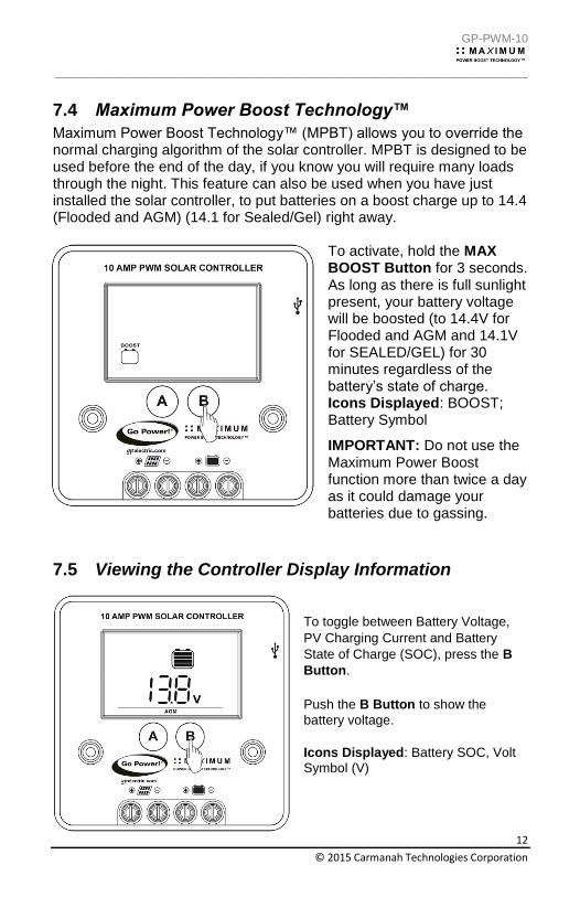
Maximum Power Boost Technology™ (MPBT) allows you to override the normal charging algorithm of the solar controller. MPBT is designed to be used before the end of the day, if you know you will require many loads through the night. This feature can also be used when you have just installed the solar controller, to put batteries on a boost charge up to 14.4 (Flooded and AGM) (14.1 for Sealed/Gel) right away.
To activate, hold the MAX BOOST Button for 3 seconds. As long as there is full sunlight present, your battery voltage will be boosted (to 14.4V for Flooded and AGM and 14.1V for SEALED/GEL) for 30 minutes regardless of the battery’s state of charge. Icons Displayed: BOOST; Battery Symbol
IMPORTANT: Do not use the Maximum Power Boost function more than twice a day as it could damage your batteries due to gassing.
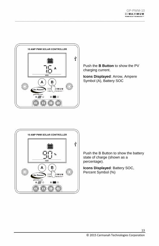
7.5 Viewing the Controller Display Information
To toggle between Battery Voltage,
PV Charging Current and Battery
State of Charge (SOC), press the B
Button.
Push the B Button to show the
battery voltage.
Icons Displayed: Battery SOC, Volt
Symbol (V)
GP-PWM-10
_________________________________________________________________________________
13
© 2015 Carmanah Technologies Corporation
Push the B Button to show the PV
charging current.
Icons Displayed: Arrow, Ampere
Symbol (A), Battery SOC
Push the B Button to show the battery state of charge (shown as a percentage).
Icons Displayed: Battery SOC,
Percent Symbol (%)
GP-PWM-10
_________________________________________________________________________________
14
© 2015 Carmanah Technologies Corporation
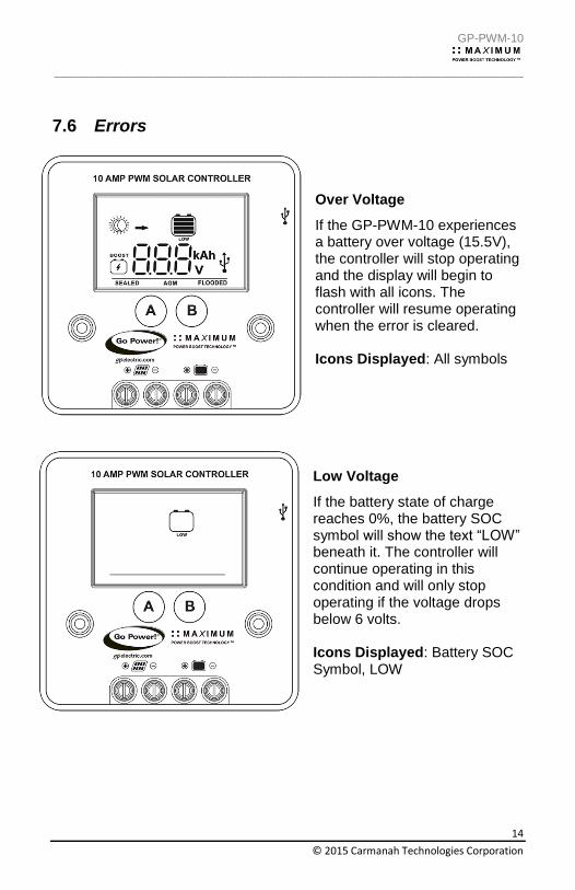
7.6 Errors
Over Voltage
If the GP-PWM-10 experiences a battery over voltage (15.5V), the controller will stop operating and the display will begin to flash with all icons. The controller will resume operating when the error is cleared. Icons Displayed: All symbols
Low Voltage
If the battery state of charge reaches 0%, the battery SOC symbol will show the text “LOW” beneath it. The controller will continue operating in this condition and will only stop operating if the voltage drops below 6 volts. Icons Displayed: Battery SOC Symbol, LOW
GP-PWM-10
_________________________________________________________________________________
15
© 2015 Carmanah Technologies Corporation
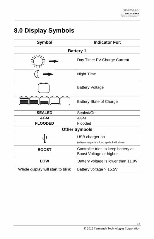
8.0 Display Symbols
Symbol Indicator For:
Battery 1
Day Time: PV Charge Current
Night Time
Battery Voltage
Battery State of Charge
SEALED Sealed/Gel
AGM AGM
FLOODED Flooded
Other Symbols
USB charger on
(When charger is off, no symbol will show)
BOOST Controller tries to keep battery at
Boost Voltage or higher
LOW Battery voltage is lower than 11.0V
Whole display will start to blink Battery voltage > 15.5V

GP-PWM-10
_________________________________________________________________________________
16
© 2015 Carmanah Technologies Corporation
Battery State of Charge
Symbol Battery Voltage
Shows only after full Boost
or Equalization Cycle
>= 12.6V
>= 11.8 -12.6V
> 11.0 -11.8V
<= 11.0V
100% Shows only after full Boost
or Equalization Cycle
90% >= 12.8V
𝑆𝑂𝐶 = 𝑏𝑎𝑡𝑡𝑒𝑟𝑦 𝑣𝑜𝑙𝑡𝑎𝑔𝑒 − 11.0𝑉
1.8𝑉∗ 90% < 12.8V and > 11.0V
0% <= 11.0V
9.0 USB Charging
The GP-PWM-10 offers a standard USB connector for delivering 5V to
small mobile appliances such as cell phones, tablets, small music
players. This charging port is capable of supplying up to 800 mA of
current.
The USB charging port is always active when the USB symbol appears
on the display.

GP-PWM-10
_________________________________________________________________________________
17
© 2015 Carmanah Technologies Corporation
The controller disables the
USB charger automatically if
the battery voltage drops
below 11.0V. If there is
enough current from the PV
panel/array available to
charge the Battery to above
12.8V, the USB terminal will
be enabled again.
Warning: Do not connect the
charging device anywhere
else! USB-Negative contact
is connected to battery
negative.
10.0 Frequently Asked Questions (FAQs) Before a problem is suspected with the system, read this section. There are numerous events that may appear as problems but are in fact perfectly normal. Please visit gpelectric.com for the most up-to-date FAQs. It seems like my flooded batteries are losing water over time. Flooded batteries may need to have distilled water added periodically to replace fluid loss during charging. Excessive water loss during a short period of time indicates the possibility of overcharging or aging batteries. When charging, my flooded batteries are emitting gas. During charging, hydrogen gas is generated within the battery. The gas bubbles stir the battery acid allowing it to receive a more full state of
charge. Important: Ensure batteries are in a well-ventilated space.
My voltmeter shows a different reading than the GP-PWM-10 display The meter value on the GP-PWM-10 display is an approximate reading intended for indication purposes only. There is an approximate 0.1 volt inherent error present that may be accentuated when compared with readings from another voltmeter.

GP-PWM-10
_________________________________________________________________________________
18
© 2015 Carmanah Technologies Corporation
There may be a slight difference between the battery voltage displayed on the GP-PWM-10 display and the battery voltage measured at the battery terminals. When troubleshooting using a voltmeter, check both the battery voltage at the GP-PWM-10 controller terminals and battery voltage at the battery terminals. If a difference of more than 0.5 volts is noted, this indicates a large voltage drop possibly caused by loose connections, long wire runs, small wire gauge, faulty wiring, a faulty voltmeter or all the above. Consult the Suggested Minimum Wire Gauge chart in Section 5 for wiring suggestions and check all connections.
11.0 Troubleshooting Problems
How to Read this Section Troubleshooting Problems is split into three sub-sections, grouped by symptoms involving key components. Components considered irrelevant in a diagnosis are denoted ‘Not Applicable’ (N/A). A multimeter or voltmeter may be required for some procedures listed. It is imperative all electrical precautions stated in the Warning Section and outlined in the Installation Section are followed. Even if it appears the system is not functioning, it should be treated as a fully functioning system generating live power.
11.1 Problems with the Display
Display Reading: Blank
Time of Day: Daytime/Nighttime
Possible Causes:
Battery or fuse connection and/or solar array connection
(Daytime only) or battery or fuse connection (Nighttime only).
How to tell:
1. Check the voltage at the controller battery terminals with a voltmeter and compare with a voltage reading at the battery terminals.
2. If there is no voltage reading at the controller battery terminals, the problem is in the wiring between the battery and the controller. If the battery voltage is lower than 6 volts the controller will not function.

GP-PWM-10
_________________________________________________________________________________
19
© 2015 Carmanah Technologies Corporation
3. For the solar array, repeat steps 1 and 2 substituting all battery terminals with solar array terminals.
Remedy:
Check all connections from the controller to the battery including
checking for correct wire polarity. Check that all connections are clean,
tight, and secure. Ensure the battery voltage is above 6 volts.
Display Reading: Nighttime
Time of Day: Daytime
Possible Causes:
Panel is covered by something; PV panel is too dirty to supply a high
enough voltage to charge the battery; PV panel is not connected.
Remedy:
Check the panel and to ensure it is not obscured. Clean the panel if it is
dirty. Check that PV cables are connected to the controller.
11.2 Problems with Voltage Voltage Reading: Inaccurate
Time of Day: Daytime/Nighttime
Possible Cause:
Excessive voltage drop from batteries to controller due to loose
connections, small wire gauge or both.
How to tell:
1. Check the voltage at the controller battery terminals with a voltmeter and compare with the voltage reading at the battery terminals.
2. If there is a voltage discrepancy of more than 0.5 V, there is an excessive voltage drop.
Remedy:
Check all connections from the controller to the battery including
checking for correct wire polarity. Check that all connections are clean,
GP-PWM-10
_________________________________________________________________________________
20
© 2015 Carmanah Technologies Corporation
tight, and secure. Shorten the distance from the controller to battery or
obtain larger gauge wire. It is also possible to double up the existing
gauge wire (i.e. two wire runs) to simulate a larger gauge wire.
11.3 Problems with Current Current Reading: 0 A
Time of Day: Daytime, clear sunny skies
Possible Cause:
Current is being limited below 1 Amp as per normal operation or
poor connection between solar array and controller.
How to tell:
1. The State of Charge (SOC) screen is close to 100% and the Sun and Battery icon are present with an arrow between.
2. With the solar array in sunlight, check the voltage at the controller solar array terminals with a voltmeter.
3. If there is no reading at the controller solar array terminals, the problem is somewhere in the wiring from the solar array to the controller.
Remedy:
1. Hold down the MAX BOOST Button for approximately 3 seconds to activate Maximum Power Boost. This will allow the controller to charge batteries to 14.4 +/- 0.1V (14.4 +/- 0.1V Sealed/Gel) with all current the solar array is producing.
2. Check all connections from the controller to the array including checking for correct wire polarity. Check that all connections are clean, tight, and secure. Continue with the solutions below for additional help on low current readings.
Current Reading: Less than expected
Time of Day: Daytime, clear sunny skies
Possible Causes:
(1) Current is being limited below 1 Amp as per normal operation.
GP-PWM-10
_________________________________________________________________________________
21
© 2015 Carmanah Technologies Corporation
(2) Incorrect series/parallel configuration and/or wiring connections
and/or wire gauge.
(3) Dirty or shaded module or lack of sun.
(4) Blown diode in solar module when two or more modules are
connected in parallel.
How to tell:
(1) Battery State of Charge screen is close to 100% and the Sun and
Battery icon are present with an arrow in between.
(2) Check that the modules and batteries are configured correctly. Check
all wiring connections.
(3) Modules look dirty, overhead object is shading modules or it is an
overcast day in which a shadow cannot be cast.
Avoid any shading no matter how small. An object as
small as a broomstick held across the solar module may
cause the power output to be reduced. Overcast days
may also cut the power output of the module.
(4) Disconnect one or both array wires from the controller. Take a
voltage reading between the positive and negative array wire. A single
12 volt module should have an open circuit voltage between 17 and 22
volts. If you have more than one solar module, you will need to conduct
this test between the positive and negative terminals of each module
junction box with either the positive or the negative wires disconnected
from the terminal.
Remedy:
(2) Reconnect in correct configuration. Tighten all connections. Check
wire gauge and length of wire run. Refer to Suggested Minimum Wire
Gauge in Section 5.
(3) Clean modules, clear obstruction or wait for conditions to clear.
(4) If the open circuit voltage of a non-connected 12 volt module is lower
than the manufacturer’s specifications, the module may be faulty. Check
for blown diodes in the solar module junction box, which may be shorting
the power output of module.
GP-PWM-10
_________________________________________________________________________________
22
© 2015 Carmanah Technologies Corporation
12.0 Limited Warranty
1. Carmanah warrants the GP-PWM-10 for a period of one (1) year from the date of shipment from its factory. This warranty is valid against defects in materials and workmanship for the one (1) year warranty period. It is not valid against defects resulting from, but not limited to:
Misuse and/or abuse, neglect or accident
Exceeding the unit’s design limits
Improper installation, including, but not limited to, improper environmental protection and improper hook-up
Acts of God, including lightning, floods, earthquakes, fire, and high winds
Damage in handling, including damage encountered during shipment
2. This warranty shall be considered void if the warranted product is
in any way opened or altered. The warranty will be void if any eyelet, rivets, or other fasteners used to seal the unit are removed or altered, or if the unit’s serial number is in any way removed, altered, replaced, defaced, or rendered illegible.
12.1 Repair and Return Information
Visit www.gpelectric.com to read the “frequently asked questions”
section of our website to troubleshoot the problem. If trouble persists:
1. Call your Go Power!® Technical Support team (1-866-247-6527).
2. Return defective product to place of purchase

GP-PWM-10
_________________________________________________________________________________
23
© 2015 Carmanah Technologies Corporation

GP-PWM-10
_________________________________________________________________________________
24
© 2015 Carmanah Technologies Corporation
© 2015 GO POWER!® By Carmanah Technologies
MOBI_MAN_GP-PWM-10_vC
gpelectric.com