Embed Size (px)
Citation preview
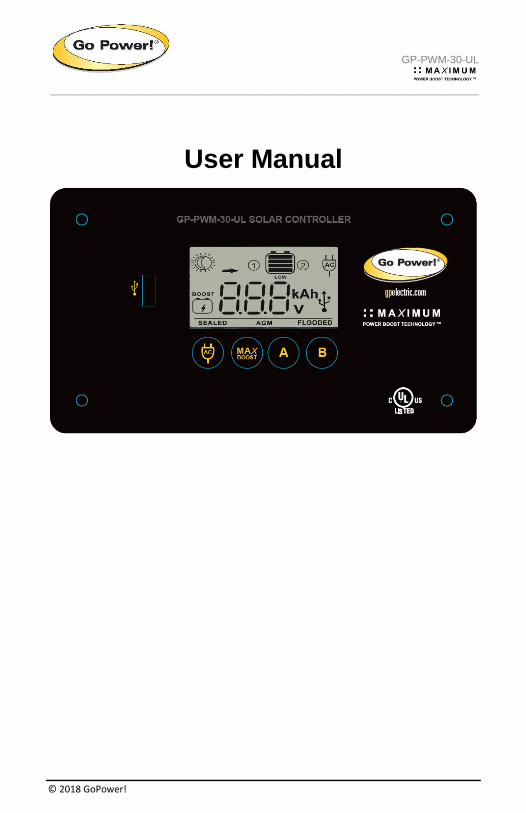
GP-PWM-30-UL
_________________________________________________________________________________
© 2018 GoPower!
User Manual
GP-PWM-30-UL
_________________________________________________________________________________
2
© 2018 GoPower!
Contents
1.0 Installation Overview 4
1.1 Introduction 4
1.2 System Voltage and Current 4
1.3 Battery Type 4
1.4 Low Voltage Disconnect Function (USB Port) 5
1.5 Regulatory Information 5
1.6 Specifications 5
2.0 IMPORTANT SAFETY INSTRUCTIONS 7
3.0 Tools and Materials Needed 8
4.0 Choosing a Location 9
5.0 Installation Instructions 10
6.0 Wiring Diagram 13
6.1 Charging Only One Battery 13
6.2 Charging Two Batteries 14
7.0 Operating Instructions 15
7.1 Power Up 15
7.2 Setting the Battery Type and Charging Profile 15
7.3 Battery Charging Profile Chart 17
7.4 Maximum Power Boost Technology™ 17
7.5 Viewing the Controller Display Information 18
7.6 Errors 20
8.0 Display Symbols 22
9.0 Inverter Control (on/off) 24
GP-PWM-30-UL
_________________________________________________________________________________
3
© 2018 GoPower!
10.0 USB Charging 25
11.0 Frequently Asked Questions (FAQs) 26
12.0 Troubleshooting Problems 28
12.1 Problems with the Display 28
12.2 Problems with Voltage 29
12.3 Problems with Current 29
13.0 Limited Warranty 32
13.1 Repair and Return Information 32
14.0 Installation Template 32
GP-PWM-30-UL
_________________________________________________________________________________
4
© 2018 GoPower!
1.0 Installation Overview
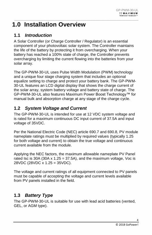
1.1 Introduction
A Solar Controller (or Charge Controller / Regulator) is an essential component of your photovoltaic solar system. The Controller maintains the life of the battery by protecting it from overcharging. When your battery has reached a 100% state of charge, the Controller prevents overcharging by limiting the current flowing into the batteries from your solar array. The GP-PWM-30-UL uses Pulse Width Modulation (PWM) technology and a unique four stage charging system that includes an optional equalize setting to charge and protect your battery bank. The GP-PWM-30-UL features an LCD digital display that shows the charge current of the solar array, system battery voltage and battery state of charge. The GP-PWM-30-UL also features Maximum Power Boost Technology™ for manual bulk and absorption charge at any stage of the charge cycle.
1.2 System Voltage and Current
The GP-PWM-30-UL is intended for use at 12 VDC system voltage and is rated for a maximum continuous DC input current of 37.5A and input voltage of 35VDC. Per the National Electric Code (NEC) article 690.7 and 690.8, PV module nameplate ratings must be multiplied by required values (typically 1.25 for both voltage and current) to obtain the true voltage and continuous current available from the module. Applying the NEC factors, the maximum allowable nameplate PV Panel rated Isc is 30A (30A x 1.25 = 37.5A), and the maximum voltage, Voc is 28VDC (28VDC x 1.25 = 35VDC). The voltage and current ratings of all equipment connected to PV panels must be capable of accepting the voltage and current levels available from PV panels installed in the field.
1.3 Battery Type
The GP-PWM-30-UL is suitable for use with lead acid batteries (vented, GEL, or AGM type).
GP-PWM-30-UL
_________________________________________________________________________________
5
© 2018 GoPower!
PV CHARGE CONTROLLER
ALSO FOR LAND VEHICLES
NO. E497008
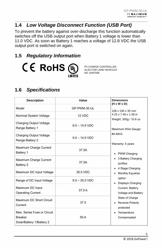
1.4 Low Voltage Disconnect Function (USB Port)
To prevent the battery against over-discharge this function automatically switches off the USB output port when Battery 1 voltage is lower than 11.0 VDC. As soon as Battery 1 reaches a voltage of 12.8 VDC the USB output port is switched on again.
1.5 Regulatory Information
1.6 Specifications
Description Value Dimensions
(H x W x D):
108 x 190 x 35 mm
4.25 x 7.48 x 1.38 in
Weight: 300g / 10.6 oz
Maximum Wire Gauge:
#4 AWG
Warranty: 5 years
• PWM Charging
• 3 Battery Charging
profiles
• 4 Stage Charging
• Monthly Equalize
option
• Displays Charging
Current, Battery
Voltage and Battery
State of Charge
• Reverse Polarity
protected
• Temperature
Compensated
Model GP-PWM-30-UL
Nominal System Voltage 12 VDC
Charging Output Voltage
Range Battery 1 9.0 – 14.9 VDC
Charging Output Voltage
Range Battery 2 9.0 – 14.9 VDC
Maximum Charge Current
Battery 1 37.5A
Maximum Charge Current
Battery 2 37.5A
Maximum DC Input Voltage 35.0 VDC
Range of DC Input Voltage 9.0 – 35.0 VDC
Maximum DC Input
Operating Current 37.5 A
Maximum DC Short Circuit
Current 37.5
Max. Series Fuse or Circuit
Breaker
Solar/Battery 1/Battery 2
50 A
GP-PWM-30-UL
_________________________________________________________________________________
6
© 2018 GoPower!
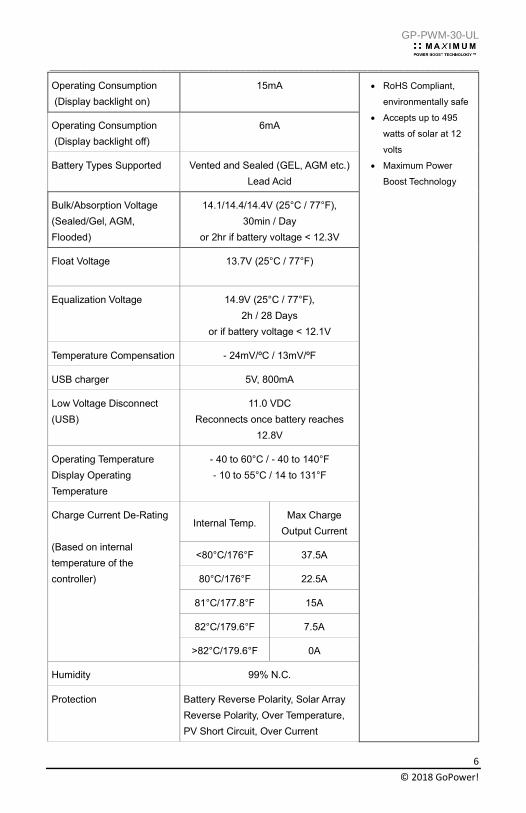
Operating Consumption
(Display backlight on)
15mA • RoHS Compliant,
environmentally safe
• Accepts up to 495
watts of solar at 12
volts
• Maximum Power
Boost Technology
Operating Consumption
(Display backlight off)
6mA
Battery Types Supported
Vented and Sealed (GEL, AGM etc.)
Lead Acid
Bulk/Absorption Voltage
(Sealed/Gel, AGM,
Flooded)
14.1/14.4/14.4V (25°C / 77°F),
30min / Day
or 2hr if battery voltage < 12.3V
Float Voltage 13.7V (25°C / 77°F)
Equalization Voltage 14.9V (25°C / 77°F),
2h / 28 Days
or if battery voltage < 12.1V
Temperature Compensation - 24mV/ºC / 13mV/ºF
USB charger 5V, 800mA
Low Voltage Disconnect
(USB)
11.0 VDC
Reconnects once battery reaches
12.8V
Operating Temperature
Display Operating
Temperature
- 40 to 60°C / - 40 to 140°F
- 10 to 55°C / 14 to 131°F
Charge Current De-Rating
(Based on internal
temperature of the
controller)
Internal Temp. Max Charge
Output Current
<80°C/176°F 37.5A
80°C/176°F 22.5A
81°C/177.8°F 15A
82°C/179.6°F 7.5A
>82°C/179.6°F 0A
Humidity 99% N.C.
Protection Battery Reverse Polarity, Solar Array
Reverse Polarity, Over Temperature,
PV Short Circuit, Over Current
GP-PWM-30-UL
_________________________________________________________________________________
7
© 2018 GoPower!
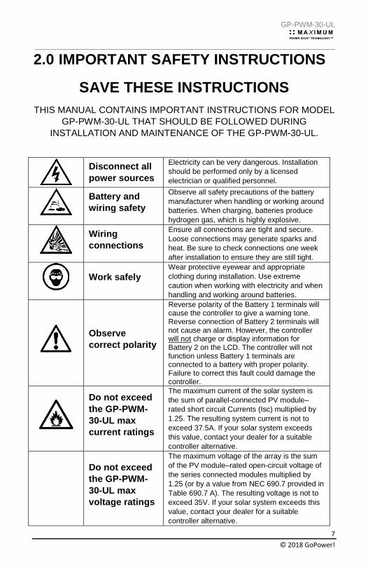
2.0 IMPORTANT SAFETY INSTRUCTIONS
SAVE THESE INSTRUCTIONS
THIS MANUAL CONTAINS IMPORTANT INSTRUCTIONS FOR MODEL
GP-PWM-30-UL THAT SHOULD BE FOLLOWED DURING
INSTALLATION AND MAINTENANCE OF THE GP-PWM-30-UL.
Disconnect all
power sources
Electricity can be very dangerous. Installation
should be performed only by a licensed
electrician or qualified personnel.
Battery and
wiring safety
Observe all safety precautions of the battery
manufacturer when handling or working around
batteries. When charging, batteries produce
hydrogen gas, which is highly explosive.
Wiring
connections
Ensure all connections are tight and secure.
Loose connections may generate sparks and
heat. Be sure to check connections one week
after installation to ensure they are still tight.
Work safely
Wear protective eyewear and appropriate
clothing during installation. Use extreme
caution when working with electricity and when
handling and working around batteries.
Observe
correct polarity
Reverse polarity of the Battery 1 terminals will cause the controller to give a warning tone. Reverse connection of Battery 2 terminals will not cause an alarm. However, the controller will not charge or display information for Battery 2 on the LCD. The controller will not function unless Battery 1 terminals are connected to a battery with proper polarity. Failure to correct this fault could damage the controller.
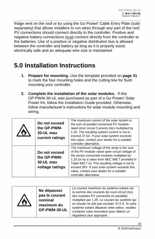
Do not exceed
the GP-PWM-
30-UL max
current ratings
The maximum current of the solar system is
the sum of parallel-connected PV module–
rated short circuit Currents (Isc) multiplied by
1.25. The resulting system current is not to
exceed 37.5A. If your solar system exceeds
this value, contact your dealer for a suitable
controller alternative.
Do not exceed
the GP-PWM-
30-UL max
voltage ratings
The maximum voltage of the array is the sum
of the PV module–rated open-circuit voltage of
the series connected modules multiplied by
1.25 (or by a value from NEC 690.7 provided in
Table 690.7 A). The resulting voltage is not to
exceed 35V. If your solar system exceeds this
value, contact your dealer for a suitable
controller alternative.
GP-PWM-30-UL
_________________________________________________________________________________
8
© 2018 GoPower!
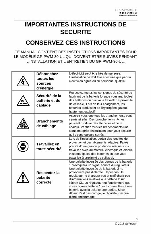
IMPORTANTES INSTRUCTIONS DE
SECURITE
CONSERVEZ CES INSTRUCTIONS
CE MANUAL CONTIENT DES INSTRUCTIONS IMPORTANTES POUR
LE MODÈLE GP-PWM-30-UL QUI DOIVENT ÊTRE SUIVIES PENDANT
L’INSTALLATION ET L’ENTRETIEN DU GP-PWM-30-UL.
Débranchez
toutes les
sources
d’énergie
L’électricité peut être très dangereuse.
L’installation ne doit être effectuée que par un
électricien agréé ou du personnel qualifié.
Sécurité de la
batterie et du
câblage
Respectez toutes les consignes de sécurité du
fabricant de la batterie lorsque vous manipulez
des batteries ou que vous travaillez à proximité
de celles-ci. Lors de leur chargement, les
batteries produisent de l’hydrogène gazeux
hautement explosif.
Branchements
de câblage
Assurez-vous que tous les branchements sont
serrés et sûrs. Des branchements lâches
peuvent produire des étincelles et de la
chaleur. Vérifiez tous les branchements une
semaine après l’installation pour vous assurer
qu’ils sont toujours serrés.
Travaillez en
toute sécurité
Lors de l’installation, portez des lunettes de
protection et des vêtements adaptés. Faites
preuve d’une grande prudence lorsque vous
travaillez avec du matériel électrique et lorsque
vous manipulez des batteries ou que vous
travaillez à proximité de celles-ci.
Respectez la
polarité
correcte
Une polarité inversée des bornes de la batterie 1 provoquera un signal sonore du régulateur. Une polarité inversée de la batterie 2 ne provoquera pas d’alarme. Cependant, le régulateur ne chargera pas et n’affichera pas d’informations relatives à la batterie 2 sur l’écran CL. Le régulateur ne fonctionnera que si ses bornes batterie 1 sont connectées à une batterie avec la polarité appropriée. Si ce défaut n’est pas corrigé, le régulateur risque d’être endommagé.
GP-PWM-30-UL
_________________________________________________________________________________
9
© 2018 GoPower!
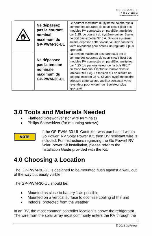
Ne dépassez
pas le courant
nominal
maximum du
GP-PWM-30-UL
Le courant maximum du système solaire est la
somme des courants de court-circuit (Isc) des
modules PV connectés en parallèle, multipliée
par 1,25. Le courant du système qui en résulte
ne doit pas excéder 37,5 A. Si votre système
solaire dépasse cette valeur, veuillez contacter
votre revendeur pour obtenir un régulateur plus
approprié.
Ne dépassez
pas la tension
nominale
maximum du
GP-PWM-30-UL
La tension maximum des panneaux est la
somme des courants de court-circuit (Isc) des
modules PV connectés en parallèle, multipliée
par 1,25 (ou par une valeur de l’article 690.7
du Code National Électrique fournie dans le
tableau 690.7 A). La tension qui en résulte ne
doit pas excéder 35 V. Si votre système solaire
dépasse cette valeur, veuillez contacter votre
revendeur pour obtenir un régulateur plus
approprié.
3.0 Tools and Materials Needed • Flathead Screwdriver (for wire terminals)
• Philips Screwdriver (for mounting screws)
If the GP-PWM-30-UL Controller was purchased with a Go Power! RV Solar Power Kit, then UV resistant wire is included. For instructions regarding the Go Power! RV Solar Power Kit installation, please refer to the Installation Guide provided with the Kit.
4.0 Choosing a Location
The GP-PWM-30-UL is designed to be mounted flush against a wall, out of the way but easily visible. The GP-PWM-30-UL should be:
• Mounted as close to battery 1 as possible
• Mounted on a vertical surface to optimize cooling of the unit
• Indoors, protected from the weather In an RV, the most common controller location is above the refrigerator. The wire from the solar array most commonly enters the RV through the
GP-PWM-30-UL
_________________________________________________________________________________
10
© 2018 GoPower!
fridge vent on the roof or by using the Go Power! Cable Entry Plate (sold separately) that allows installers to run wires through any part of the roof. PV connections should connect directly to the controller. Positive and negative battery connections must connect directly from the controller to the batteries. Use of a positive or negative distribution bus is allowed between the controller and battery as long as it is properly sized, electrically safe and an adequate wire size is maintained.
5.0 Installation Instructions
1. Prepare for mounting. Use the template provided on page 31 to mark the four mounting holes and the cutting line for flush mounting your controller.
2. Complete the installation of the solar modules. If this
GP-PWM-30-UL was purchased as part of a Go Power! Solar Power Kit, follow the Installation Guide provided. Otherwise, follow manufacturer’s instructions for solar module mounting and wiring.
Do not exceed
the GP-PWM-
30-UL max
current ratings
The maximum current of the solar system is
the sum of parallel-connected PV module–
rated short circuit Currents (Isc) multiplied by
1.25. The resulting system current is not to
exceed 37.5A. If your solar system exceeds
this value, contact your dealer for a suitable
controller alternative.
Do not exceed
the GP-PWM-
30-UL max
voltage ratings
The maximum voltage of the array is the sum
of the PV module–rated open-circuit voltage of
the series connected modules multiplied by
1.25 (or by a value from NEC 690.7 provided in
Table 690.7 A). The resulting voltage is not to
exceed 35V. If your solar system exceeds this
value, contact your dealer for a suitable
controller alternative.
Ne dépassez
pas le courant
nominal
maximum du
GP-PWM-30-UL
Le courant maximum du système solaire est
la somme des courants de court-circuit (Isc)
des modules PV connectés en parallèle,
multipliée par 1,25. Le courant du système qui
en résulte ne doit pas excéder 37,5 A. Si votre
système solaire dépasse cette valeur, veuillez
contacter votre revendeur pour obtenir un
régulateur plus approprié.
GP-PWM-30-UL
_________________________________________________________________________________
11
© 2018 GoPower!
Ne dépassez
pas la tension
nominale
maximum du
GP-PWM-30-UL
La tension maximum des panneaux est la
somme des courants de court-circuit (Isc) des
modules PV connectés en parallèle, multipliée
par 1,25 (ou par une valeur de l’article 690.7
du Code National Électrique fournie dans le
tableau 690.7 A). La tension qui en résulte ne
doit pas excéder 35 V. Si votre système
solaire dépasse cette valeur, veuillez
contacter votre revendeur pour obtenir un
régulateur plus approprié.
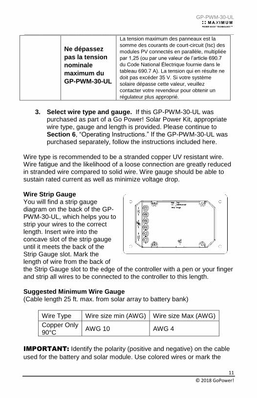
3. Select wire type and gauge. If this GP-PWM-30-UL was
purchased as part of a Go Power! Solar Power Kit, appropriate wire type, gauge and length is provided. Please continue to Section 6, “Operating Instructions.” If the GP-PWM-30-UL was purchased separately, follow the instructions included here.
Wire type is recommended to be a stranded copper UV resistant wire. Wire fatigue and the likelihood of a loose connection are greatly reduced in stranded wire compared to solid wire. Wire gauge should be able to sustain rated current as well as minimize voltage drop. Wire Strip Gauge You will find a strip gauge diagram on the back of the GP-PWM-30-UL, which helps you to strip your wires to the correct length. Insert wire into the concave slot of the strip gauge until it meets the back of the Strip Gauge slot. Mark the length of wire from the back of the Strip Gauge slot to the edge of the controller with a pen or your finger and strip all wires to be connected to the controller to this length. Suggested Minimum Wire Gauge (Cable length 25 ft. max. from solar array to battery bank)
Wire Type Wire size min (AWG) Wire size Max (AWG)
Copper Only 90°C
AWG 10 AWG 4
IMPORTANT: Identify the polarity (positive and negative) on the cable
used for the battery and solar module. Use colored wires or mark the
GP-PWM-30-UL
_________________________________________________________________________________
12
© 2018 GoPower!
wire ends with tags. Although the GP-PWM-30-UL is protected, a reverse polarity contact may damage the unit. Wiring the GP-PWM-30-UL. Wire the GP-PWM-30-UL according to the wiring schematic in Section 6. Run wires from the solar array and the batteries to the location of the GP-PWM-30-UL. Keep the solar array covered with an opaque material until all wiring is completed.
IMPORTANT: All wiring must be in accordance to National Electrical
Code, ANSI/NFPA 70.
4. Connect the battery wiring to the controller first and then connect the battery wiring to the battery.
5. Torque all terminal screws per the following:
Stranded Copper 90°C Wire
Wire Size AWG Rated Torque (in-lbs)
10 20
8 25
6 35
4 35
With battery power attached, the controller should power up and display information. Connect the solar wiring to the controller and remove the opaque material from the solar array. The negative solar array and battery wiring must be connected directly to the controller for proper operation. Do not connect the negative solar array or negative battery controller wiring to the chassis of the vehicle.
6. Mounting the GP-PWM-30-UL. Mount the GP-PWM-30-UL to the wall using the included four mounting screws.
IMPORTANT: You must set the battery type on the GP-PWM-30-UL
before you begin to use the controller. The default battery setting is for AGM batteries. Congratulations, your GP-PWM-30-UL should now be operational. If the battery power is low and the solar array is producing power, your battery should begin to charge.
7. Re-torque: After 30 days of operation, re-torque all terminal screws to ensure the wires are properly secured to the controller
GP-PWM-30-UL
_________________________________________________________________________________
13
© 2018 GoPower!
WARNING: This unit is not provided with a GFDI device. This charge controller must be used with an external GFDI device as required by Article 690 of the National Electric Code for the
installation location.
AVERTISSEMENT : Cet appareil n’est pas équipé d’un détecteur de défaut de terre. Ce régulateur de charge doit être utilisé avec un détecteur de défaut de terre comme l’exige
l’article 690 du Code National Électrique pour l’emplacement de l’installation.
6.0 Wiring Diagram The GP-PWM-30-UL Maximum 37.5A rating is based on a 30 amp total maximum short circuit current rating (Isc) from the solar modules nameplate ratings. The National Electric Code specifies the PV equipment/system rating to be 125% of the maximum Isc from the PV module ratings (1.25 times 30 = 37.5A). E.G. Three modules in parallel with an Isc of 7 amps each equal a total Isc input of 21 amps. When selecting PV modules for use with the GP-PWM-30-UL do not exceed a total nameplate Isc current of 30A. Solar modules list the Isc amps on their specifications nameplate label.
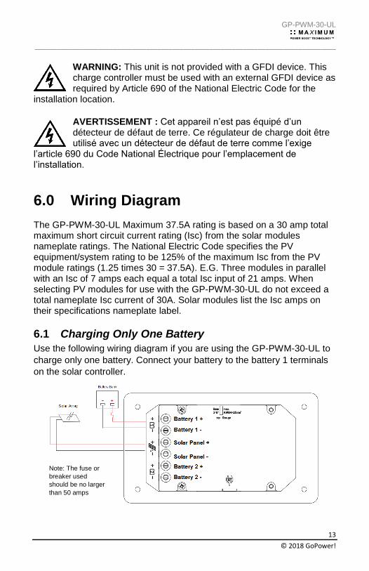
6.1 Charging Only One Battery
Use the following wiring diagram if you are using the GP-PWM-30-UL to
charge only one battery. Connect your battery to the battery 1 terminals
on the solar controller.
Note: The fuse or
breaker used
should be no larger
than 50 amps
GP-PWM-30-UL
_________________________________________________________________________________
14
© 2018 GoPower!
The controller will not work unless there is a battery
connected to the Battery 1 terminals
WARNING: When the photovoltaic (solar) array is
exposed to light, it supplies a dc voltage to this
equipment
AVERTISSEMENT : Lorsque le panneau photovoltaïque (solaire) est exposé à la lumière, il fournit une tension cc à cet équipement.
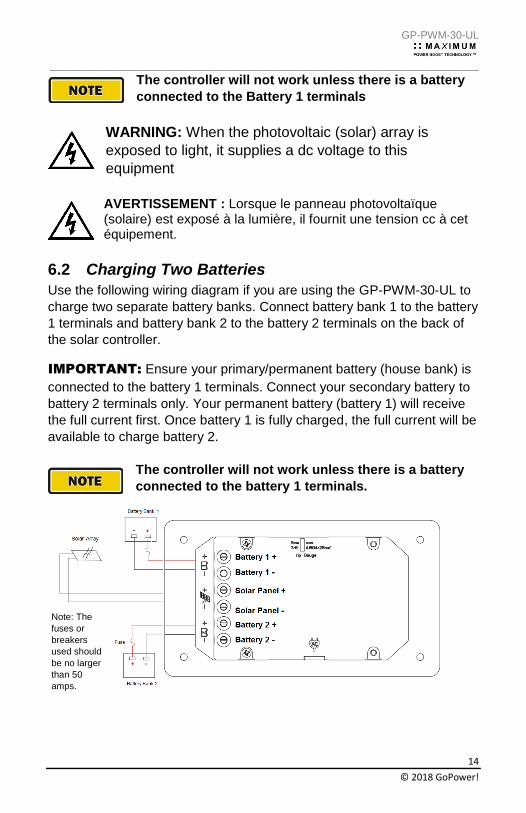
6.2 Charging Two Batteries
Use the following wiring diagram if you are using the GP-PWM-30-UL to
charge two separate battery banks. Connect battery bank 1 to the battery
1 terminals and battery bank 2 to the battery 2 terminals on the back of
the solar controller.
IMPORTANT: Ensure your primary/permanent battery (house bank) is
connected to the battery 1 terminals. Connect your secondary battery to
battery 2 terminals only. Your permanent battery (battery 1) will receive
the full current first. Once battery 1 is fully charged, the full current will be
available to charge battery 2.
The controller will not work unless there is a battery
connected to the battery 1 terminals.
Note: The
fuses or
breakers
used should
be no larger
than 50
amps.
GP-PWM-30-UL
_________________________________________________________________________________
15
© 2018 GoPower!
WARNING: When the photovoltaic (solar) array is
exposed to light, it supplies a dc voltage to this
equipment
AVERTISSEMENT : Lorsque le panneau photovoltaïque (solaire) est exposé à la lumière, il fournit une tension cc à cet équipement.
7.0 Operating Instructions
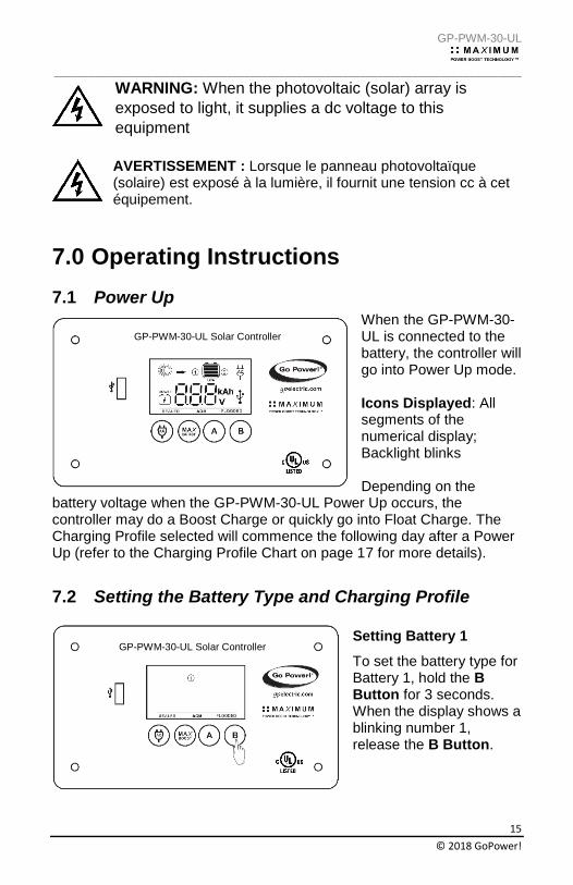
7.1 Power Up
When the GP-PWM-30-UL is connected to the battery, the controller will go into Power Up mode. Icons Displayed: All segments of the numerical display; Backlight blinks Depending on the
battery voltage when the GP-PWM-30-UL Power Up occurs, the controller may do a Boost Charge or quickly go into Float Charge. The Charging Profile selected will commence the following day after a Power Up (refer to the Charging Profile Chart on page 17 for more details).
7.2 Setting the Battery Type and Charging Profile
Setting Battery 1
To set the battery type for Battery 1, hold the B Button for 3 seconds. When the display shows a blinking number 1, release the B Button.
GP-PWM-30-UL Solar Controller
GP-PWM-30-UL Solar Controller
GP-PWM-30-UL
_________________________________________________________________________________
16
© 2018 GoPower!
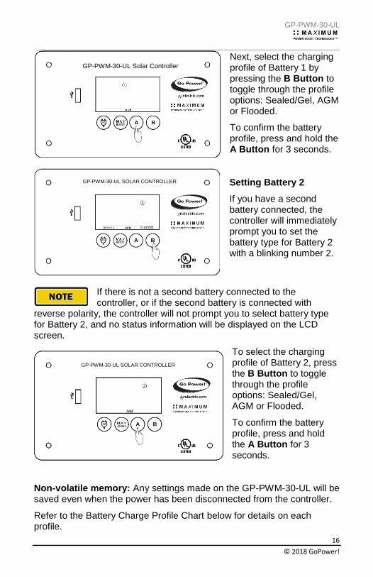
Next, select the charging profile of Battery 1 by pressing the B Button to toggle through the profile options: Sealed/Gel, AGM or Flooded.
To confirm the battery profile, press and hold the A Button for 3 seconds.
Setting Battery 2
If you have a second battery connected, the controller will immediately prompt you to set the battery type for Battery 2 with a blinking number 2.
If there is not a second battery connected to the controller, or if the second battery is connected with
reverse polarity, the controller will not prompt you to select battery type for Battery 2, and no status information will be displayed on the LCD screen.
To select the charging profile of Battery 2, press the B Button to toggle through the profile options: Sealed/Gel, AGM or Flooded.
To confirm the battery profile, press and hold the A Button for 3 seconds.
Non-volatile memory: Any settings made on the GP-PWM-30-UL will be saved even when the power has been disconnected from the controller.
Refer to the Battery Charge Profile Chart below for details on each profile.
GP-PWM-30-UL Solar Controller
GP-PWM-30-UL Solar Controller
GP-PWM-30-UL Solar Controller GP-PWM-30-UL SOLAR CONTROLLER
GP-PWM-30-UL SOLAR CONTROLLER
GP-PWM-30-UL SOLAR CONTROLLER
GP-PWM-30-UL
_________________________________________________________________________________
17
© 2018 GoPower!
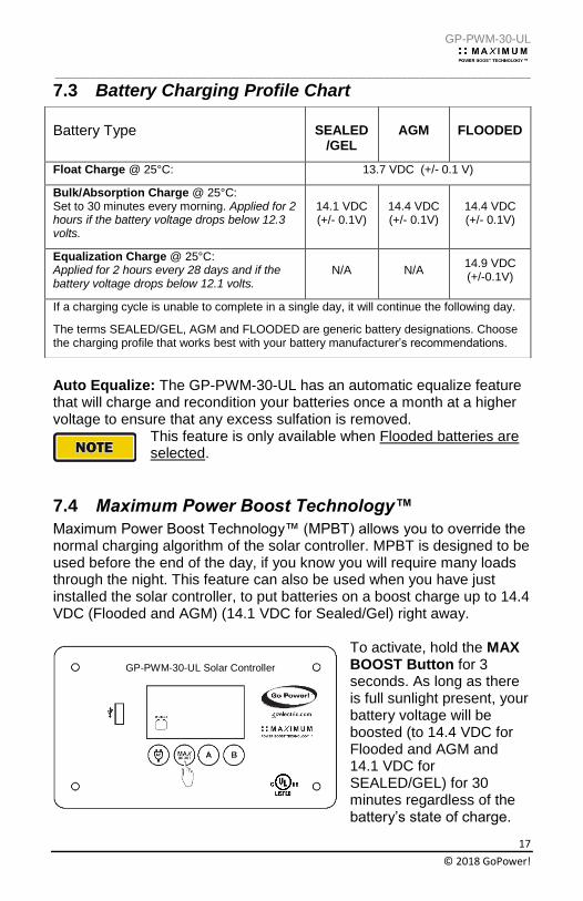
7.3 Battery Charging Profile Chart
Auto Equalize: The GP-PWM-30-UL has an automatic equalize feature that will charge and recondition your batteries once a month at a higher voltage to ensure that any excess sulfation is removed.
This feature is only available when Flooded batteries are selected.
7.4 Maximum Power Boost Technology™
Maximum Power Boost Technology™ (MPBT) allows you to override the normal charging algorithm of the solar controller. MPBT is designed to be used before the end of the day, if you know you will require many loads through the night. This feature can also be used when you have just installed the solar controller, to put batteries on a boost charge up to 14.4 VDC (Flooded and AGM) (14.1 VDC for Sealed/Gel) right away.
To activate, hold the MAX BOOST Button for 3 seconds. As long as there is full sunlight present, your battery voltage will be boosted (to 14.4 VDC for Flooded and AGM and 14.1 VDC for SEALED/GEL) for 30 minutes regardless of the battery’s state of charge.
Battery Type
SEALED /GEL
AGM FLOODED
Float Charge @ 25°C: 13.7 VDC (+/- 0.1 V)
Bulk/Absorption Charge @ 25°C: Set to 30 minutes every morning. Applied for 2 hours if the battery voltage drops below 12.3 volts.
14.1 VDC (+/- 0.1V)
14.4 VDC (+/- 0.1V)
14.4 VDC (+/- 0.1V)
Equalization Charge @ 25°C: Applied for 2 hours every 28 days and if the battery voltage drops below 12.1 volts.
N/A N/A 14.9 VDC (+/-0.1V)
If a charging cycle is unable to complete in a single day, it will continue the following day.
The terms SEALED/GEL, AGM and FLOODED are generic battery designations. Choose the charging profile that works best with your battery manufacturer’s recommendations.
GP-PWM-30-UL Solar Controller
GP-PWM-30-UL
_________________________________________________________________________________
18
© 2018 GoPower!
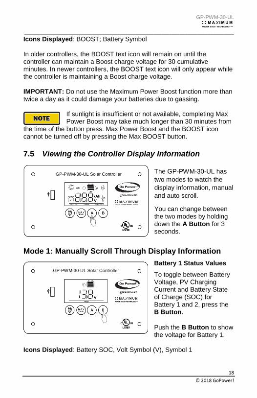
Icons Displayed: BOOST; Battery Symbol In older controllers, the BOOST text icon will remain on until the controller can maintain a Boost charge voltage for 30 cumulative minutes. In newer controllers, the BOOST text icon will only appear while the controller is maintaining a Boost charge voltage. IMPORTANT: Do not use the Maximum Power Boost function more than twice a day as it could damage your batteries due to gassing.
If sunlight is insufficient or not available, completing Max Power Boost may take much longer than 30 minutes from
the time of the button press. Max Power Boost and the BOOST icon cannot be turned off by pressing the Max BOOST button.
7.5 Viewing the Controller Display Information
The GP-PWM-30-UL has
two modes to watch the
display information, manual
and auto scroll.
You can change between the two modes by holding down the A Button for 3 seconds.
Mode 1: Manually Scroll Through Display Information
Battery 1 Status Values
To toggle between Battery Voltage, PV Charging Current and Battery State of Charge (SOC) for Battery 1 and 2, press the B Button.
Push the B Button to show the voltage for Battery 1.
Icons Displayed: Battery SOC, Volt Symbol (V), Symbol 1
GP-PWM-30-UL Solar Controller
GP-PWM-30-UL Solar Controller
GP-PWM-30-UL
_________________________________________________________________________________
19
© 2018 GoPower!
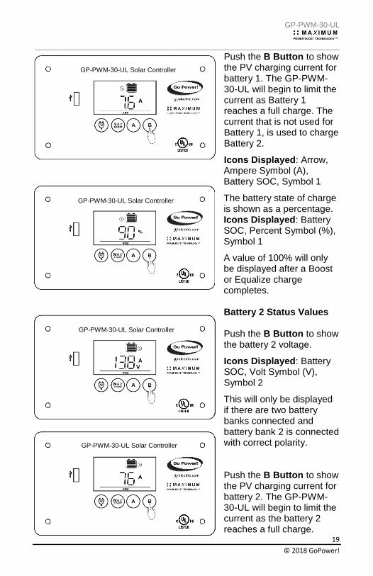
Push the B Button to show the PV charging current for battery 1. The GP-PWM-30-UL will begin to limit the current as Battery 1 reaches a full charge. The current that is not used for Battery 1, is used to charge Battery 2.
Icons Displayed: Arrow, Ampere Symbol (A), Battery SOC, Symbol 1
The battery state of charge is shown as a percentage. Icons Displayed: Battery SOC, Percent Symbol (%), Symbol 1
A value of 100% will only be displayed after a Boost or Equalize charge completes.
Battery 2 Status Values Push the B Button to show the battery 2 voltage.
Icons Displayed: Battery SOC, Volt Symbol (V), Symbol 2
This will only be displayed if there are two battery banks connected and battery bank 2 is connected with correct polarity. Push the B Button to show the PV charging current for battery 2. The GP-PWM-30-UL will begin to limit the current as the battery 2 reaches a full charge.
GP-PWM-30-UL Solar Controller
GP-PWM-30-UL Solar Controller
GP-PWM-30-UL Solar Controller
GP-PWM-30-UL Solar Controller
GP-PWM-30-UL
_________________________________________________________________________________
20
© 2018 GoPower!
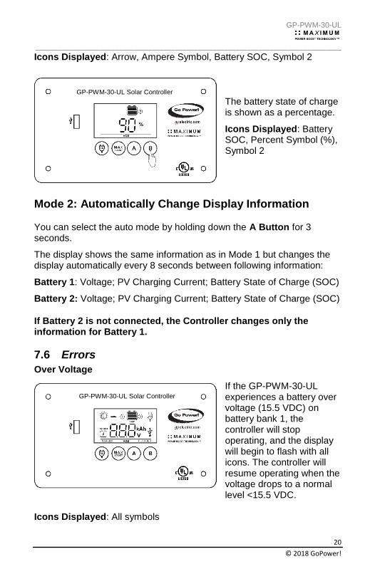
Icons Displayed: Arrow, Ampere Symbol, Battery SOC, Symbol 2
The battery state of charge is shown as a percentage.
Icons Displayed: Battery SOC, Percent Symbol (%), Symbol 2
Mode 2: Automatically Change Display Information
You can select the auto mode by holding down the A Button for 3 seconds.
The display shows the same information as in Mode 1 but changes the display automatically every 8 seconds between following information:
Battery 1: Voltage; PV Charging Current; Battery State of Charge (SOC)
Battery 2: Voltage; PV Charging Current; Battery State of Charge (SOC)
If Battery 2 is not connected, the Controller changes only the information for Battery 1.
7.6 Errors
Over Voltage
If the GP-PWM-30-UL experiences a battery over voltage (15.5 VDC) on battery bank 1, the controller will stop operating, and the display will begin to flash with all icons. The controller will resume operating when the voltage drops to a normal level <15.5 VDC.
Icons Displayed: All symbols
GP-PWM-30-UL Solar Controller
GP-PWM-30-UL Solar Controller
GP-PWM-30-UL
_________________________________________________________________________________
21
© 2018 GoPower!
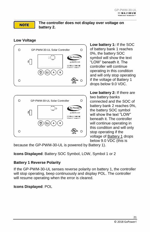
The controller does not display over voltage on battery 2.
Low Voltage
Low battery 1: If the SOC of battery bank 1 reaches 0%, the battery SOC symbol will show the text “LOW” beneath it. The controller will continue operating in this condition and will only stop operating if the voltage of Battery 1 drops below 9.0 VDC. Low battery 2: If there are two battery banks connected and the SOC of battery bank 2 reaches 0%, the battery SOC symbol will show the text “LOW” beneath it. The controller will continue operating in this condition and will only stop operating if the voltage of Battery 1 drops below 9.0 VDC (this is
because the GP-PWM-30-UL is powered by Battery 1). Icons Displayed: Battery SOC Symbol, LOW, Symbol 1 or 2 Battery 1 Reverse Polarity
If the GP-PWM-30-UL senses reverse polarity on battery 1, the controller will stop operating, beep continuously and display POL. The controller will resume operating when the error is cleared. Icons Displayed: POL
GP-PWM-30-UL Solar Controller
GP-PWM-30-UL Solar Controller
GP-PWM-30-UL
_________________________________________________________________________________
22
© 2018 GoPower!
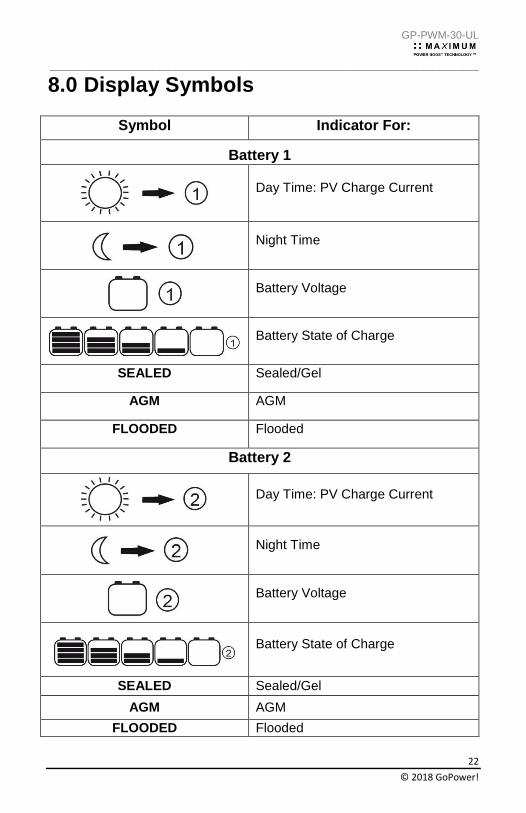
8.0 Display Symbols
Symbol Indicator For:
Battery 1
Day Time: PV Charge Current
Night Time
Battery Voltage
Battery State of Charge
SEALED Sealed/Gel
AGM AGM
FLOODED Flooded
Battery 2
Day Time: PV Charge Current
Night Time
Battery Voltage
Battery State of Charge
SEALED Sealed/Gel
AGM AGM
FLOODED Flooded
GP-PWM-30-UL
_________________________________________________________________________________
23
© 2018 GoPower!
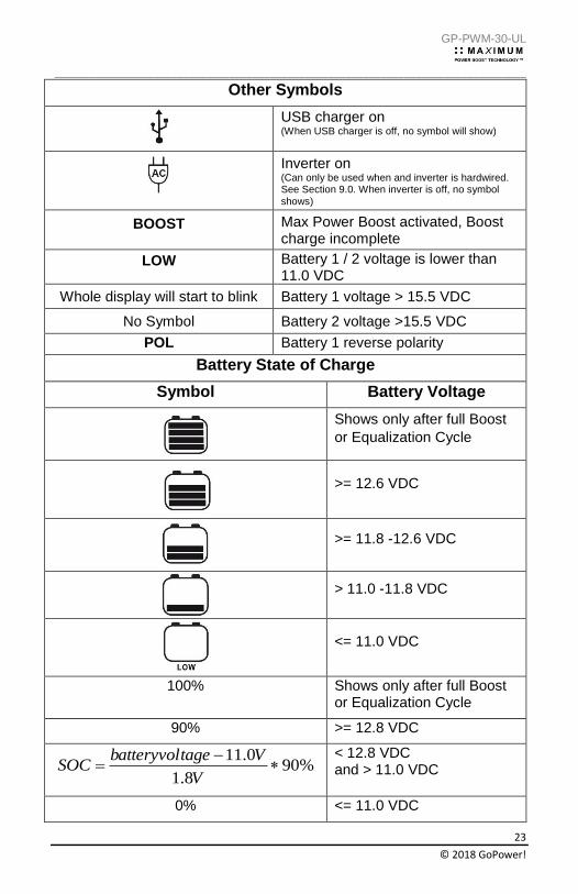
Other Symbols
USB charger on (When USB charger is off, no symbol will show)
Inverter on (Can only be used when and inverter is hardwired. See Section 9.0. When inverter is off, no symbol shows)
BOOST Max Power Boost activated, Boost charge incomplete
LOW Battery 1 / 2 voltage is lower than 11.0 VDC
Whole display will start to blink Battery 1 voltage > 15.5 VDC
No Symbol Battery 2 voltage >15.5 VDC
POL Battery 1 reverse polarity
Battery State of Charge
Symbol Battery Voltage
Shows only after full Boost
or Equalization Cycle
>= 12.6 VDC
>= 11.8 -12.6 VDC
> 11.0 -11.8 VDC
<= 11.0 VDC
100% Shows only after full Boost or Equalization Cycle
90% >= 12.8 VDC
%908.1
0.11
V
VtagebatteryvolSOC
< 12.8 VDC and > 11.0 VDC
0% <= 11.0 VDC
GP-PWM-30-UL
_________________________________________________________________________________
24
© 2018 GoPower!
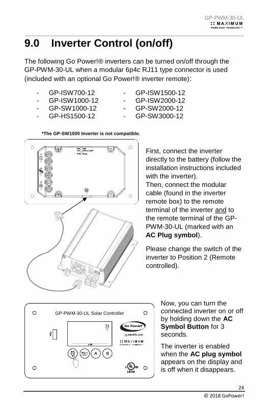
*The GP-SW1500 Inverter is not compatible.
9.0 Inverter Control (on/off)
The following Go Power!® inverters can be turned on/off through the
GP-PWM-30-UL when a modular 6p4c RJ11 type connector is used
(included with an optional Go Power!® inverter remote):
- GP-ISW700-12 - GP-ISW1000-12 - GP-SW1000-12 - GP-HS1500-12
- GP-ISW1500-12 - GP-ISW2000-12 - GP-SW2000-12 - GP-SW3000-12
First, connect the inverter
directly to the battery (follow the
installation instructions included
with the inverter). Then, connect the modular
cable (found in the inverter
remote box) to the remote
terminal of the inverter and to
the remote terminal of the GP-
PWM-30-UL (marked with an
AC Plug symbol).
Please change the switch of the
inverter to Position 2 (Remote
controlled).
Now, you can turn the connected inverter on or off by holding down the AC Symbol Button for 3 seconds.
The inverter is enabled when the AC plug symbol appears on the display and is off when it disappears.
GP-PWM-30-UL Solar Controller
GP-PWM-30-UL
_________________________________________________________________________________
25
© 2018 GoPower!
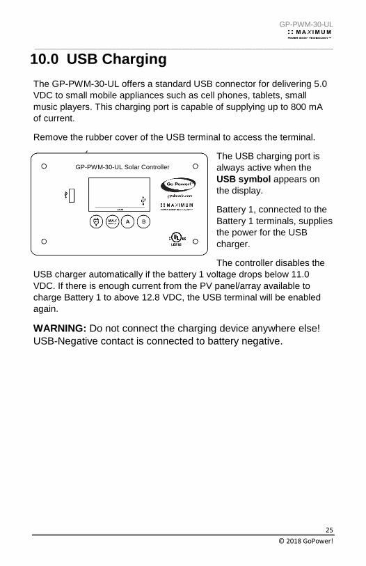
10.0 USB Charging
The GP-PWM-30-UL offers a standard USB connector for delivering 5.0
VDC to small mobile appliances such as cell phones, tablets, small
music players. This charging port is capable of supplying up to 800 mA
of current.
Remove the rubber cover of the USB terminal to access the terminal.
The USB charging port is
always active when the
USB symbol appears on
the display.
Battery 1, connected to the
Battery 1 terminals, supplies
the power for the USB
charger.
The controller disables the
USB charger automatically if the battery 1 voltage drops below 11.0
VDC. If there is enough current from the PV panel/array available to
charge Battery 1 to above 12.8 VDC, the USB terminal will be enabled
again.
WARNING: Do not connect the charging device anywhere else!
USB-Negative contact is connected to battery negative.
GP-PWM-30-UL Solar Controller
GP-PWM-30-UL
_________________________________________________________________________________
26
© 2018 GoPower!
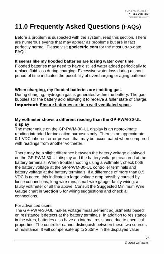
11.0 Frequently Asked Questions (FAQs) Before a problem is suspected with the system, read this section. There are numerous events that may appear as problems but are in fact perfectly normal. Please visit gpelectric.com for the most up-to-date FAQs. It seems like my flooded batteries are losing water over time. Flooded batteries may need to have distilled water added periodically to replace fluid loss during charging. Excessive water loss during a short period of time indicates the possibility of overcharging or aging batteries.
When charging, my flooded batteries are emitting gas. During charging, hydrogen gas is generated within the battery. The gas bubbles stir the battery acid allowing it to receive a fuller state of charge.
Important: Ensure batteries are in a well-ventilated space.
My voltmeter shows a different reading than the GP-PWM-30-UL display The meter value on the GP-PWM-30-UL display is an approximate reading intended for indication purposes only. There is an approximate 0.1 VDC inherent error present that may be accentuated when compared with readings from another voltmeter. There may be a slight difference between the battery voltage displayed on the GP-PWM-30-UL display and the battery voltage measured at the battery terminals. When troubleshooting using a voltmeter, check both the battery voltage at the GP-PWM-30-UL controller terminals and battery voltage at the battery terminals. If a difference of more than 0.5 VDC is noted, this indicates a large voltage drop possibly caused by loose connections, long wire runs, small wire gauge, faulty wiring, a faulty voltmeter or all the above. Consult the Suggested Minimum Wire Gauge chart in Section 5 for wiring suggestions and check all connections. For advanced users: The GP-PWM-30-UL makes voltage measurement adjustments based on resistance it detects at the battery terminals. In addition to resistance in the wires, batteries also have an internal resistance due to chemical properties. The controller cannot distinguish between these two sources of resistance. It will compensate up to 250mV in the displayed value.
GP-PWM-30-UL
_________________________________________________________________________________
27
© 2018 GoPower!
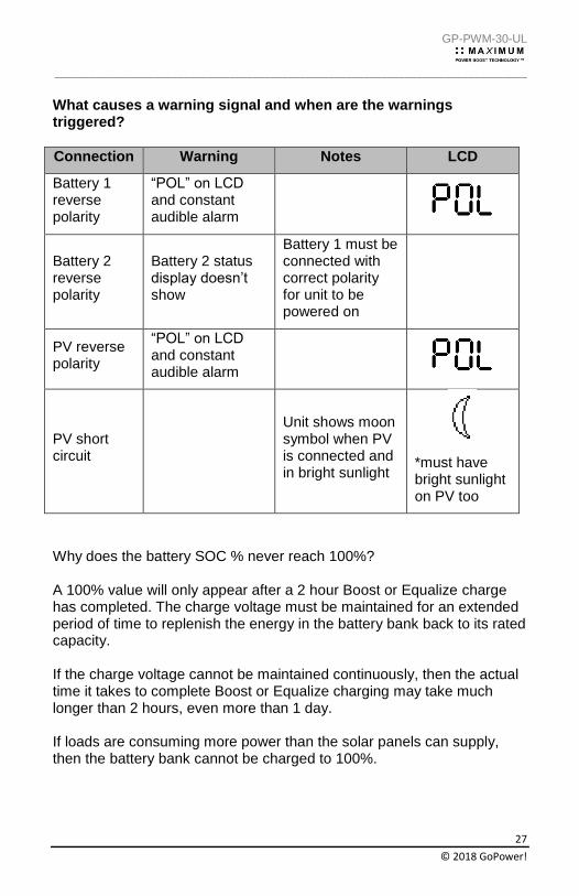
What causes a warning signal and when are the warnings triggered?
Connection Warning Notes LCD
Battery 1 reverse polarity
“POL” on LCD and constant audible alarm
Battery 2 reverse polarity
Battery 2 status display doesn’t show
Battery 1 must be connected with correct polarity for unit to be powered on
PV reverse polarity
“POL” on LCD and constant audible alarm
PV short circuit
Unit shows moon symbol when PV is connected and in bright sunlight
*must have bright sunlight on PV too
Why does the battery SOC % never reach 100%? A 100% value will only appear after a 2 hour Boost or Equalize charge has completed. The charge voltage must be maintained for an extended period of time to replenish the energy in the battery bank back to its rated capacity. If the charge voltage cannot be maintained continuously, then the actual time it takes to complete Boost or Equalize charging may take much longer than 2 hours, even more than 1 day. If loads are consuming more power than the solar panels can supply, then the battery bank cannot be charged to 100%.
GP-PWM-30-UL
_________________________________________________________________________________
28
© 2018 GoPower!
12.0 Troubleshooting Problems
How to Read this Section Troubleshooting Problems is split into three sub-sections, grouped by symptoms involving key components. Components considered irrelevant in a diagnosis are denoted ‘Not Applicable’ (N/A). A multimeter or voltmeter may be required for some procedures listed. It is imperative all electrical precautions stated in the Warning Section and outlined in the Installation Section are followed. Even if it appears the system is not functioning, it should be treated as a fully functioning system generating live power.
12.1 Problems with the Display
Display Reading: Blank
Time of Day: Daytime/Nighttime
Possible Causes:
Battery or fuse connection and/or solar array connection
(Daytime only) or battery or fuse connection (Nighttime only).
How to tell:
1. Check the voltage at the controller battery terminals with a voltmeter and compare with a voltage reading at the battery terminals.
2. If there is no voltage reading at the controller battery terminals, the problem could be a fuse, or the wiring between the battery and the controller. If the battery voltage is lower than 6 volts the controller will not function.
3. For the solar array, repeat steps 1 and 2 substituting all battery terminals with solar array terminals.
Remedy:
Check all connections from the controller to the battery including
checking for correct wire polarity. Check that all connections are clean,
tight, and secure. Ensure the battery voltage is above 6 volts.
Display Reading: Nighttime
Time of Day: Daytime
GP-PWM-30-UL
_________________________________________________________________________________
29
© 2018 GoPower!
Possible Causes:
Panel is covered by something; PV panel is too dirty to supply a high
enough voltage to charge the battery; PV panel is not connected.
Remedy:
Check the panel and to ensure it is not obscured. Clean the panel if it is dirty. Check that PV cables are connected to the controller.
12.2 Problems with Voltage Voltage Reading: Inaccurate
Time of Day: Daytime/Nighttime
Possible Cause:
Excessive voltage drop from batteries to controller due to loose
connections, small wire gauge or both.
How to tell:
1. Check the voltage at the controller battery terminals with a voltmeter and compare with the voltage reading at the battery terminals.
2. If there is a voltage discrepancy of more than 0.5 VDC, there is an excessive voltage drop.
Remedy:
Check all connections from the controller to the battery including
checking for correct wire polarity. Check that all connections are clean,
tight, and secure. Shorten the distance from the controller to battery or
obtain larger gauge wire. It is also possible to double up the existing
gauge wire (i.e. two wire runs) to simulate a larger gauge wire.
12.3 Problems with Current Current Reading: 0 A
Time of Day: Daytime, clear sunny skies
Possible Cause:
Current is being limited below 1 Amp as per normal operation or
poor connection between solar array and controller.
GP-PWM-30-UL
_________________________________________________________________________________
30
© 2018 GoPower!
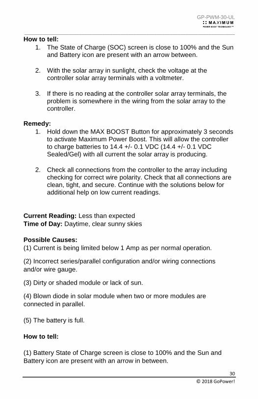
How to tell:
1. The State of Charge (SOC) screen is close to 100% and the Sun and Battery icon are present with an arrow between.
2. With the solar array in sunlight, check the voltage at the controller solar array terminals with a voltmeter.
3. If there is no reading at the controller solar array terminals, the problem is somewhere in the wiring from the solar array to the controller.
Remedy:
1. Hold down the MAX BOOST Button for approximately 3 seconds to activate Maximum Power Boost. This will allow the controller to charge batteries to 14.4 +/- 0.1 VDC (14.4 +/- 0.1 VDC Sealed/Gel) with all current the solar array is producing.
2. Check all connections from the controller to the array including checking for correct wire polarity. Check that all connections are clean, tight, and secure. Continue with the solutions below for additional help on low current readings.
Current Reading: Less than expected
Time of Day: Daytime, clear sunny skies
Possible Causes:
(1) Current is being limited below 1 Amp as per normal operation.
(2) Incorrect series/parallel configuration and/or wiring connections
and/or wire gauge.
(3) Dirty or shaded module or lack of sun.
(4) Blown diode in solar module when two or more modules are
connected in parallel.
(5) The battery is full.
How to tell:
(1) Battery State of Charge screen is close to 100% and the Sun and
Battery icon are present with an arrow in between.
GP-PWM-30-UL
_________________________________________________________________________________
31
© 2018 GoPower!
(2) Check that the modules and batteries are configured correctly. Check
all wiring connections.
(3) Modules look dirty, overhead object is shading modules or it is an
overcast day in which a shadow cannot be cast.
Avoid any shading no matter how small. An object as
small as a broomstick held across the solar module may
cause the power output to be reduced. Overcast days may also cut the
power output of the module.
(4) Disconnect one or both array wires from the controller. Take a
voltage reading between the positive and negative array wire. A single
12 volt module should have an open circuit voltage between 17 and 23
VDC. If you have more than one solar module, you will need to conduct
this test between the positive and negative terminals of each module
junction box with either the positive or the negative wires disconnected
from the terminal.
Remedy:
(2) Reconnect in correct configuration. Tighten all connections. Check
wire gauge and length of wire run. Refer to Suggested Minimum Wire
Gauge in Section 5.
(3) Clean modules, clear obstruction or wait for conditions to clear.
(4) If the open circuit voltage of a non-connected 12 volt module is lower
than the manufacturer’s specifications, the module may be faulty. Check
for blown diodes in the solar module junction box, which may be shorting
the power output of module.
GP-PWM-30-UL
_________________________________________________________________________________
32
© 2018 GoPower!
13.0 Limited Warranty
1. Go Power! warrants the GP-PWM-30-UL for a period of five (5) years from the date of shipment from its factory. This warranty is valid against defects in materials and workmanship for the five (5) year warranty period. It is not valid against defects resulting from, but not limited to:
• Misuse and/or abuse, neglect or accident
• Exceeding the unit’s design limits
• Improper installation, including, but not limited to, improper environmental protection and improper hook-up
• Acts of God, including lightning, floods, earthquakes, fire, and high winds
• Damage in handling, including damage encountered during shipment
2. This warranty shall be considered void if the warranted product is
in any way opened or altered. The warranty will be void if any eyelet, rivets, or other fasteners used to seal the unit are removed or altered, or if the unit’s serial number is in any way removed, altered, replaced, defaced, or rendered illegible.
13.1 Repair and Return Information
Visit www.gpelectric.com to read the “frequently asked questions”
section of our website to troubleshoot the problem. If trouble persists:
1. Call your Go Power!® Technical Support team (1-866-247-6527).
2. Return defective product to place of purchase
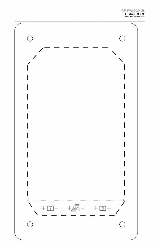
14.0 Installation Template Use the template on page 34 for flush mounting the controller.
GP-PWM-30-UL
_________________________________________________________________________________
33
© 2018 GoPower!

GP-PWM-30-UL
_________________________________________________________________________________
34
© 2018 GoPower!
© 2018 GO POWER!® By Valterra Products, LLC
MOBI_MAN_GP-PWM-30-UL_vG
gpelectric.com