Embed Size (px)
Citation preview

BMF 720
USER MANUAL CRANE

BMF 720 Forestcrane Page 1 of 15
Contents
1 WARRANTY ............................................................. 1
2 INTRODUCTION ....................................................... 2
3 SAFETY..................................................................... 2
3.1 General............................................................ 2
3.2 Safety distances .............................................. 2
3.3 Hydraulic system ............................................. 2
3.4 Operation ........................................................ 3
4 TECHNICAL DATA .................................................... 3
4.1 Dimensions of the forest crane ...................... 3
4.2 Grapples .......................................................... 4
4.3 Technical data ................................................. 5
4.4 Lifting Power diagram ..................................... 5
5 ASSEMBLY AND MOUNTING ................................... 5
5.1 Mounting forest crane to BMF trailers ........... 5
5.2 Mounting control valve ................................... 6
6 HYDRAULIC SYSTEM ................................................ 6
6.1 Connection ...................................................... 6
6.2 Hydraulic diagram and control functions ....... 6
6.3 Shock valves .................................................... 7
7 OPERATING INSTRUCTIONS .................................... 7
7.1 Testing ............................................................. 7
7.2 Practice runs ................................................... 7
8 DETACHING FOREST CRANE .................................... 8
9 STORAGE INSTRUCTIONS ........................................ 8
10 MAINTENANCE .................................................... 8
10.1 Maintenance ................................................... 8
10.2 Changing oil in slewing device ........................ 8
10.3 Lubrication ...................................................... 9
10.4 Changing the hydraulic oil .............................. 9
11 TROUBLESHOOTING .......................................... 10
12 SPARE PARTS ..................................................... 11
12.1 Housing of Slewing Device ............................ 12
12.2 Main boom .................................................... 13
12.3 Extension Boom ............................................ 14
12.4 Telescope ...................................................... 15
1 WARRANTY
Product warranty is valid for one year starting from
the date of delivery or issuing an invoice. Product
warranty is valid only in case if:
• all instructions in this manual were followed
• during the maintenance original spare parts
were used
• maintenance work was performed by qualified
specialists
• forest crane was not overloaded
• proper pressure was used in the hydraulic
system.
Product warranty is NOT VALID in case of user’s
incompetence and/or irrespective handling of the
equipment. Warranty does not cover
transportation cost or loss of profit due to normal
abrasion or product failure.
Producer:
OÜ Lisako

BMF 720 Forestcrane Page 2 of 15
2 INTRODUCTION
This manual gives you a detailed overview about forest crane BMF 720. Read the manual carefully before you start using this machine. The manual contains essential di-rections for efficient and safe use of this equip-ment. These instructions should always be fol-lowed. This forest crane is constructed for loading works in forestry and agriculture. It can be mounted on BMF forest trailers by unified connection. This for-est crane has also 3-point linkage, by which it can be connected directly to agricultural tractors. This machine meets all technical standards and safety regulations of EU Machinery Directive and its amendments. Forest crane is fitted out with CE marking.
Operator of forest crane is obliged to be aware of and strictly follow all safety precautions and instructions described in this manual. In addition to this, instructions of local occupational safety authorities, as well national laws and regulations, must be followed.
Using the machine for other tasks than those for which it is intended or exceeding its performance is not allowed. The manufacturer/dealer is not responsible for damage caused by misuse of the forest crane.
Pay attention to regular maintenance. In case there will occur problems with forest crane, which are not covered in this manual, contact authorized dealer or manufacturer.
3 SAFETY
3.1 GENERAL Read the manual carefully before you start operating with forest crane. Use forest crane only for right purposes. The operator must have a proper valid license to work with the tractor and the forest crane and has sufficient training to use this machine. Notice, avoid and prevent all potentially hazardous situations.
IT IS STRONGLY FORBIDDEN:
• to use forest crane in state
of intoxication by alcohol, drugs
or other psychoactive
substances
• to exceed maximum
loading values
• to leave the load in UP position without
supervision
• to use forest crane for lifting people
• to rebuild forest crane
• to use repairing materials without the
producer’s permission
• to localize a leakage from hydraulic hoses
or connections by hand
BEFORE YOU START OPERATING FOREST CRANE, MAKE SURE THAT: • crane is in working condition
• you have full visibility over all the working
area
• crane is placed firmly on even ground
• the tractor parking brake is engaged
3.2 SAFETY DISTANCES General safety distance for working with forest crane is 20 meters! Follow special safety distance when working close
to live electrical conductors:
Rated voltage, kV Safety area, m Up to 0,5 2 Up to 20 10 35 – 110 25 220 – 330 40
Table 1 Safety area
All live electrical conductors must be clearly visible while operating with forest crane
3.3 HYDRAULIC SYSTEM Hydraulic system must be
serviced by qualified and
experienced hydraulics mechanic
only

BMF 720 Forestcrane Page 3 of 15
• Continually inspect the condition of hydraulic
system. Repair all safety endangering defects
immediately
• Before hydraulics maintenance work make
sure that the system is not pressurized
• When replacing hydraulic components and
hoses, use original spare parts or parts
recommended by the manufacturer
• When performing maintenance work, use
safety goggles and gloves
• Prevent oil dripping to the ground to avoid
environment pollution
• When working in ecologically sensitive areas,
use bio-oil
3.4 OPERATION • Ensure, that forest crane is
in good working condition
• Ensure, that you have
control over all the working area
• Operating with damaged or defective machine
is prohibited
• Prevent entering unauthorized persons to the
working area
• Support legs must be used while working with
forest crane
• Be sure not to endanger anyone while lowering
the support legs
• Use tractor’s parking brake during working with
forest crane
• Do not use an equipment, which is not
recommended by the producer
• Never lift heavier load, than stated by the
manufacturer
• Pull the support legs up before moving the
tractor
• When leaving the machine, always secure it
from unauthorized access and unintended
operation
• Manufacturer is not responsible for damage or
loss that is caused by misuse or incorrect,
careless and inappropriate use of the machine
4 TECHNICAL DATA
4.1 DIMENSIONS OF THE FOREST CRANE
Figure 1 BMF 720 dimensions (mm) and lifting power on different distances
BMF 720 Forestcrane Page 4 of 15
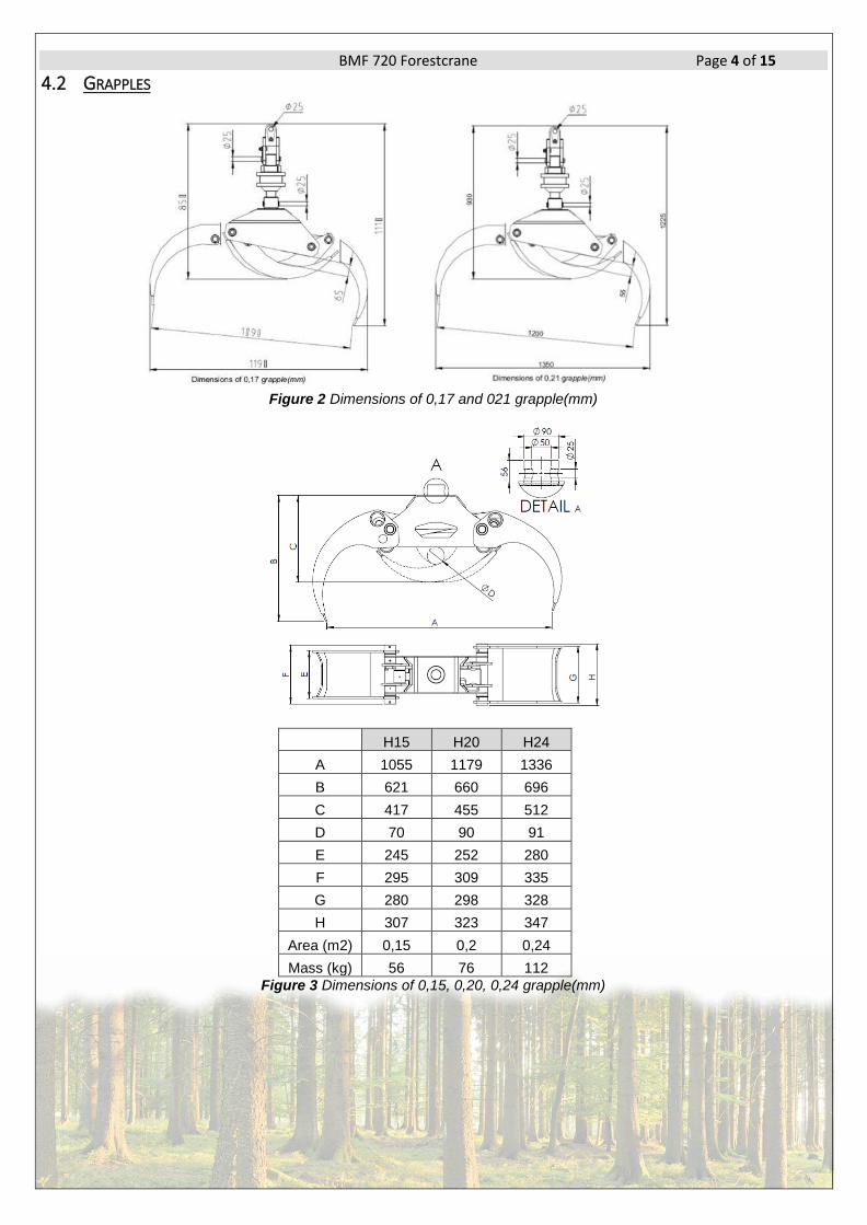
4.2 GRAPPLES
Figure 2 Dimensions of 0,17 and 021 grapple(mm)
H15 H20 H24
A 1055 1179 1336
B 621 660 696
C 417 455 512
D 70 90 91
E 245 252 280
F 295 309 335
G 280 298 328
H 307 323 347
Area (m2) 0,15 0,2 0,24
Mass (kg) 56 76 112
Figure 3 Dimensions of 0,15, 0,20, 0,24 grapple(mm)
BMF 720 Forestcrane Page 5 of 15
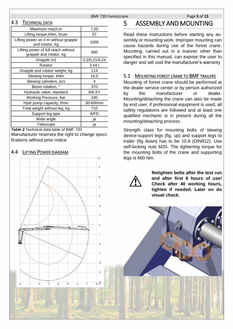
4.3 TECHNICAL DATA Maximum reach,m 7,20
Lifting torque,kNm, bruto 57
Lifting power on 4 m without grapple and rotator, kg
1000
Lifting power of full reach without grapple and rotator, kg
560
Grapple m2 0,2/0,21/0,24
Rotator 3 t/4 t
Grapple and rotator weight, kg 114
Slewing torque, kNm 14,5
Slewing cylinders, pcs 4
Boom rotation, ° 370
Hydraulic valve, standard 6/8 XY
Working Pressure, bar 190
Hydr pump capacity, l/min 30-60l/min
Total weight without leg, kg 710
Support leg type A/FD
Wide angle ja
Telescope ja
Table 2 Technical data table of BMF 720
Manufacturer reserves the right to change speci-
fications without prior notice
4.4 LIFTING POWER DIAGRAM
5 ASSEMBLY AND MOUNTING
Read these instructions before starting any as-
sembly or mounting work. Improper mounting can
cause hazards during use of the forest crane.
Mounting, carried out in a manner other than
specified in this manual, can expose the user to
danger and will void the manufacturer’s warranty
5.1 MOUNTING FOREST CRANE TO BMF TRAILERS Mounting of forest crane should be performed at
the dealer service center or by person authorized
by the manufacturer or dealer.
Mounting/detaching the crane can also be made
by end user, if professional equipment is used, all
safety regulations are followed and at least one
qualified mechanic is in present during all the
mounting/detaching process.
Strength class for mounting bolts of slewing
device-support legs (fig. up) and support legs to
trailer (fig down) has to be 10.8 (DIN912). Use
self-locking nuts M20. The tightening torque for
the mounting bolts of the crane and supporting
legs is 660 Nm.
Retighten bolts after the test run
and after first 8 hours of use!
Check after 40 working hours,
tighten if needed. Later on do
visual check.

BMF 720 Forestcrane Page 6 of 15
5.2 MOUNTING CONTROL VALVE
The valve must be installed in the
way that levers cannot be used
inadvertently!
Install the valve at desired location using the
included bracket. Leave enough space for hoses
to avoid risk of abrasion or clamping while working
with forest crane.
Hoses in the operator’s cabin
must be covered in the way that
the user is protected from the di-
rect oil jets in case of hose break-
age!
6 HYDRAULIC SYSTEM
6.1 CONNECTION Before connecting forest crane to the tractor’s hydraulic system, make sure that the oils are compatible. Forest crane has been tested using HLP 46 hydraulic oil. Check the hydraulic oil level. We recommend connecting the pressure hose to the single-acting hydraulic outlet and the return hose to the tank via the return filter. The filter’s intended minimum flow rate is 30-50 l/min and the filtering density is 10-50 μm. Make sure you connect the return hose
always first and disconnect it last. Make sure the
connection has made properly.
Ensure, that the control valve’s pressure line (P) has been con-nected properly and that the re-turn line (T) is unobstructed. In case there is obstruction in re-turn line (quick couplings are not connected or are not locked properly) the pressure might rise over 10 bar and cause malfunc-tion of control valve
Forest crane can also be connected to the double-acting hydraulics outlet. If this option will be used make sure, that the lever of the double-acting valve is in the right position and the pressure is directed to the pressure connection of the crane’s control valve. Check also vehicle’s operating man-ual for hydraulic system connecting instructions.
All BMF forest crane control
valves are fitted with the one-
way flow valve, which protects
control valve in case return
line is by mistake connected
to pressure line. If pump is di-
rectly connected to cranes
control valve return line, there
will be danger of breaking
pump or hoses from overpres-
sure, because one-way flow
valve will block oil flow in
wrong direction
6.2 HYDRAULIC DIAGRAM AND CONTROL FUNCTIONS
Figure 4 Hydraulic diagram with HC 6/8 XY controlvalve
BMF 720 Forestcrane Page 7 of 15
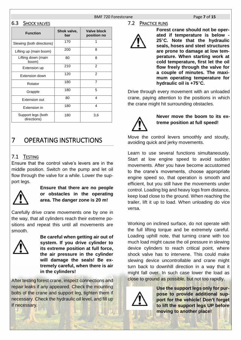
6.3 SHOCK VALVES
Function Shok valve,
bar Valve block position no
Slewing (both directions) 170
1
Lifting up (main boom) 200
8
Lifting down (main boom)
80
8
Extension up 210
2
Extension down 120
2
Rotator 180
7
Grapple 180
5
Extension out 80
4
Extension in 180
4
Support legs (both directions)
180
3,6
7 OPERATING INSTRUCTIONS
7.1 TESTING Ensure that the control valve’s levers are in the
middle position. Switch on the pump and let oil
flow through the valve for a while. Lower the sup-
port legs.
Ensure that there are no people
or obstacles in the operating
area. The danger zone is 20 m!
Carefully drive crane movements one by one in
the way, that all cylinders reach their extreme po-
sitions and repeat this until all movements are
smooth.
Be careful when getting air out of
system. If you drive cylinder to
its extreme position at full force,
the air pressure in the cylinder
will damage the seals! Be ex-
tremely careful, when there is air
in the cylinders!
After testing forest crane, inspect connections and
repair leaks if any appeared. Check the mounting
bolts of the crane and support leg, tighten them if
necessary. Check the hydraulic oil level, and fill up
if necessary.
7.2 PRACTICE RUNS Forest crane should not be oper-ated if temperature is below -25°C. Note that the hydraulic seals, hoses and steel structures are prone to damage at low tem-perature. When starting work at cold temperature, first let the oil flow freely through the valve for a couple of minutes. The maxi-mum operating temperature for hydraulic oil is +75°C.
Drive through every movement with an unloaded
crane, paying attention to the positions in which
the crane might hit surrounding obstacles.
Never move the boom to its ex-
treme position at full speed!
Move the control levers smoothly and stoutly, avoiding quick and jerky movements. Learn to use several functions simultaneously.
Start at low engine speed to avoid sudden
movements. After you have become accustomed
to the crane’s movements, choose appropriate
engine speed so, that operation is smooth and
efficient, but you still have the movements under
control. Loading big and heavy logs from distance,
keep load close to the ground. When reaching the
trailer, lift it up to load. When unloading do vice
versa.
Working on inclined surface, do not operate with
the full lifting torque and be extremely careful.
Loading uphill note, that turning crane with too
much load might cause the oil pressure in slewing
device cylinders to reach critical point, where
shock valve has to intervene. This could make
slewing device uncontrollable and crane might
turn back to downhill direction in a way that it
might fall over. In such case lower the load as
close to ground as possible, but not too rapidly.
Use the support legs only for pur-
pose to provide additional sup-
port for the vehicle! Don’t forget
to lift the support legs UP before
moving to another place!
BMF 720 Forestcrane Page 8 of 15
Support legs are equipped with extra valves,
which will keep them in working position in case
feeding hoses of support leg cylinder breaks
Do not exceed the speed limit
when driving! Adjust speed
according to the road and
weather conditions. Be
especially careful on turns! For
driving always attach crane by
grapple to trailers frame. When
driving with load, leave one log
sticking out from pile and attach
crane by grapple to it. Keep crane
boom as low as possible.
8 DETACHING FOREST CRANE
Choose sufficiently hard and level ground for detaching forest crane. Ensure, that no unauthorized persons are around during detaching and storing process. When storing control valve, make sure it is out of the reach of children. • Lower the support legs to support crane
proparly • Fix crane firmly by proper hoist • Make sure that crane cannot lean over • Detach quick couplings and put covers on
them
Always switch the pump off be-
fore disconnecting quick cou-
plings!
Detach crane from the vehicle
9 STORAGE INSTRUCTIONS
• Clean forest crane and if necessary, touch up any points, where paint has peeled off
• Lubricate forest crane thoroughly (see lubricating instructions)
• Release pressure from the cylinders • Protect the cylinder piston rods and exposed
parts of the control valve with grease • Store forest crane in a sheltered area (under
the roof), avoid direct contact with the ground.
10 MAINTENANCE
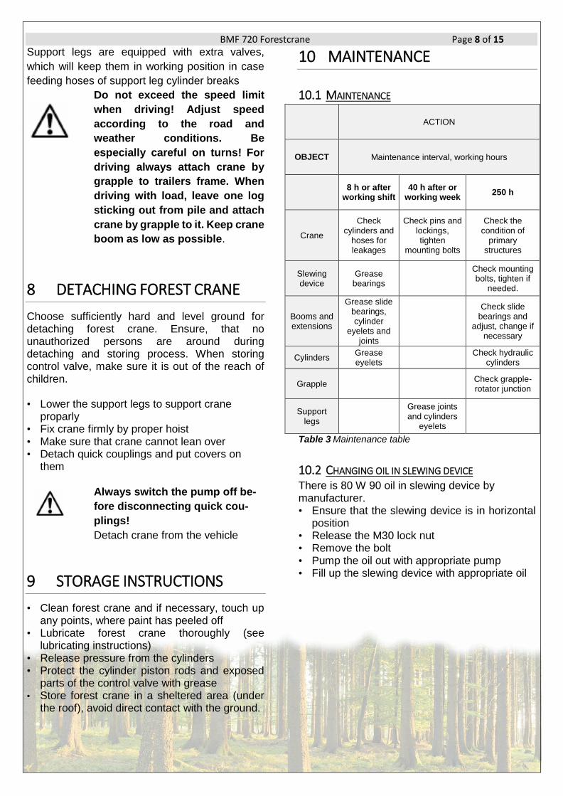
10.1 MAINTENANCE
ACTION
OBJECT Maintenance interval, working hours
8 h or after
working shift 40 h after or
working week 250 h
Crane
Check cylinders and
hoses for leakages
Check pins and lockings, tighten
mounting bolts
Check the condition of
primary structures
Slewing device
Grease bearings
Check mounting bolts, tighten if
needed.
Booms and extensions
Grease slide bearings, cylinder
eyelets and joints
Check slide bearings and
adjust, change if necessary
Cylinders Grease eyelets
Check hydraulic
cylinders
Grapple Check grapple-rotator junction
Support legs
Grease joints and cylinders
eyelets
Table 3 Maintenance table
10.2 CHANGING OIL IN SLEWING DEVICE There is 80 W 90 oil in slewing device by manufacturer. • Ensure that the slewing device is in horizontal
position • Release the M30 lock nut • Remove the bolt • Pump the oil out with appropriate pump • Fill up the slewing device with appropriate oil

BMF 720 Forestcrane Page 9 of 15
→
Oil level has to be up to the oil window (A) lower edge!
• Screw the bolt up to contact with the rack and tighten 15 – 30 Nm
• Screw up the M30 (B) lock nut.
Follow environmental conditions. Collect wasted oil in a container. Hydraulic oil is rec-ommended to be changed once in 2 years
10.3 LUBRICATION Using the appropriate lubricants like Beacon EP2, Multipurpose GR Moly, Mobilux EP2, Mobil Grease MP Special, Energrease LS-EP2 or similar. Right lubricants guarantee troublefree operation
of the machine.
.
Lubrication point Qty Action
Interval, h Notes
Slewing device
Bearings A 1 Greasing 8 2 % molybden
sulfide
Slewing device F 1 Oil 2000 MU1045
Super Tractor
Booms
Joint C 2 Greasing 8 2 % molybden
sulfide
Cylinder eyelet B 4 Greasing 8
Rotator
Joint C 1 8
Table 4 Lubrication
10.4 CHANGING THE HYDRAULIC OIL Change the oil according to the vehicle’s mainte-
nance recommendations. Forest crane hydraulic
system has been filled with HLP 46 hydraulic oil at
the factory. If the oil temperature does not exceed
75°C in summer, winter oil can be used all year
round.
• Freezing point must be below -50°C • Viscosity must not be lower than 1.5 E°, +50°C
for piston pumps and 2.5 E°, + 50°C for gear pumps
• Hydraulic oil must contain the necessary additives for lubrication, rust protection and defoaming
BMF 720 Forestcrane Page 10 of 15
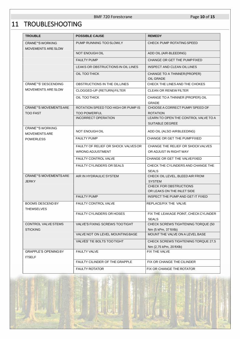
11 TROUBLESHOOTING
TROUBLE POSSIBLE CAUSE REMEDY
CRANE’*S WORKING
MOVEMENTS ARE SLOW
PUMP RUNNING TOO SLOWLY CHECK PUMP ROTATING SPEED
NOT ENOUGH OIL ADD OIL (AIR-BLEEDING)
FAULTY PUMP CHANGE OR GET THE PUMP FIXED
LEAKS OR OBSTRUCTIONS IN OIL LINES INSPECT AND CLEAN OIL LINES
OIL TOO THICK CHANGE TO A THINNER (PROPER)
OIL GRADE CRANE’*S’ DESCENDING
MOVEMENTS ARE SLOW
OBSTRUCTIONS IN THE OIL LINES CHECK THE LINES AND THE CHOKES
CLOGGED-UP (RETURN) FILTER CLEAN OR RENEW FILTER
OIL TOO THICK CHANGE TO A THINNER (PROPER) OIL
GRADE CRANE’*S MOVEMENTS ARE
TOO FAST
ROTATION SPEED TOO HIGH OR PUMP IS
TOO POWERFUL
CHOOSE A CORRECT PUMP/ SPEED OF
ROTATION
INCORRECT OPERATION LEARN TO OPEN THE CONTROL VALVE TO A
SUITABLE DEGREE CRANE’*S WORKING
MOVEMENTS ARE
POWERLESS
NOT ENOUGH OIL
ADD OIL (ALSO AIR BLEEDING)
FAULTY PUMP CHANGE OR GET THE PUMP FIXED
FAULTY OF RELIEF OR SHOCK VALVES OR
WRONG ADJUSTMENT CHANGE THE RELIEF OR SHOCK VALVES
OR ADJUST IN RIGHT WAY
FAULTY CONTROL VALVE CHANGE OR GET THE VALVE FIXED
FAULTY CYLINDERS OR SEALS CHECK THE CYLINDERS AND CHANGE THE
SEALS CRANE’*S MOVEMENTS ARE
JERKY AIR IN HYDRAULIC SYSTEM CHECK OIL LEVEL, BLEED AIR FROM
SYSTEM
CHECK FOR OBSTRUCTIONS
OR LEAKS ON THE INLET SIDE FAULTY PUMP INSPECT THE PUMP AND GET IT FIXED
BOOMS DESCEND BY
THEMSELVES
FAULTY CONTROL VALVE REPLACE/FIX THE VALVE
FAULTY CYLINDERS OR HOSES FIX THE LEAKAGE POINT, CHECK CYLINDER
SEALS CONTROL VALVE STEMS
STICKING VALVE’S FIXING SCREWS TOO TIGHT CHECK SCREWS TIGHTENING TORQUE (50
Nm (5 kPm, 37 ftXlb)
VALVE NOT ON LEVEL MOUNTING BASE MOUNT THE VALVE ON A LEVEL BASE
VALVES’ TIE BOLTS TOO TIGHT CHECK SCREWS TIGHTENING TORQUE 27,5
Nm (2,75 kPm, 20 ftXlb) GRAPPLE’S OPENING BY
ITSELF
FAULTY VALVE FIX THE VALVE
FAULTY CILINDER OF THE GRAPPLE FIX OR CHANGE THE CILINDER
FAULTY ROTATOR FIX OR CHANGE THE ROTATOR
BMF 720 Forestcrane Page 11 of 15
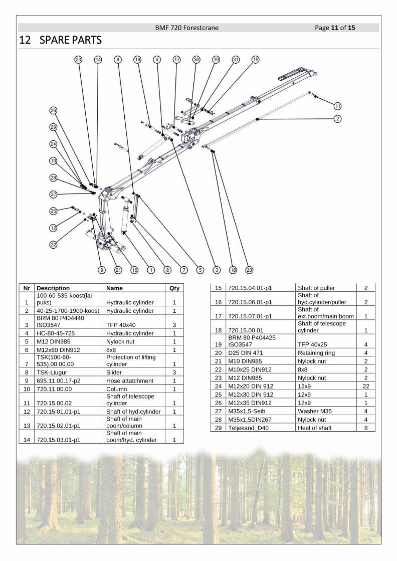
12 SPARE PARTS
Nr Description Name Qty
1 100-60-535-koost(lai puks) Hydraulic cylinder 1
2 40-25-1700-1900-koost Hydraulic cylinder 1
3 BRM 80 P404440 ISO3547 TFP 40x40 3
4 HC-80-45-725 Hydraulic cylinder 1
5 M12 DIN985 Nylock nut 1
6 M12x60 DIN912 8x8 1
7 TSK(100-60-535).00.00.00
Protection of lifting cylinder 1
8 TSK-Liugur Slider 3
9 695.11.00.17-p2 Hose attatchment 1
10 720.11.00.00 Column 1
11 720.15.00.02 Shaft of telescope cylinder 1
12 720.15.01.01-p1 Shaft of hyd.cylinder 1
13 720.15.02.01-p1 Shaft of main boom/column 1
14 720.15.03.01-p1 Shaft of main boom/hyd. cylinder 1
15 720.15.04.01-p1 Shaft of puller 2
16 720.15.06.01-p1 Shaft of hyd.cylinder/puller 2
17 720.15.07.01-p1 Shaft of ext.boom/main boom 1
18 720.15.00.01 Shaft of telescope cylinder 1
19 BRM 80 P404425 ISO3547 TFP 40x25 4
20 D25 DIN 471 Retaining ring 4
21 M10 DIN985 Nylock nut 2
22 M10x25 DIN912 8x8 2
23 M12 DIN985 Nylock nut 2
24 M12x20 DIN 912 12x9 22
25 M12x30 DIN 912 12x9 1
26 M12x35 DIN912 12x9 1
27 M35x1,5-Seib Washer M35 4
28 M35x1,5DIN267 Nylock nut 4
29 Teljekand_D40 Heel of shaft 8

BMF 720 Forestcrane Page 12 of 15
12.1 HOUSING OF SLEWING DEVICE
Nr Description Name Qty
1 1_2'' oilcap Oil cap 1
2 1_2'' oilwindow Oil window 1
3 22217CCW33 JP Bearing 1
4 90_447_A6.18.00.00 Hollow D90 4
5 BFP 150x155x60 HOLE Bronze slide bearing 1
6 FPK 90x70x22,4 Seal 4
7 HVD155.18.00.02 Locking nut M80x2 1
8 Hammaslatt-m8z18 Gear rack D90 L620 2
9 M14 DIN127 Washer 24
10 M14x40 DIN912 12x9 24
11 M30-DIN936 Nut 1
12 M6x20 DIN7991 10x9 4
13 MK04.18.00.07-P1 Cover 1
15 MK06.18.00.00-P2
Housing of slewing de-
vice 1
16 Poordkast.00.01 Support bolt 2
17 Ret_rind_D150 DIN472 Retaining ring D150 1
18 Tihend A6 157x101x1,5 Seal 4
19 Poordkast.00.02 Bronze 2
BMF 720 Forestcrane Page 13 of 15
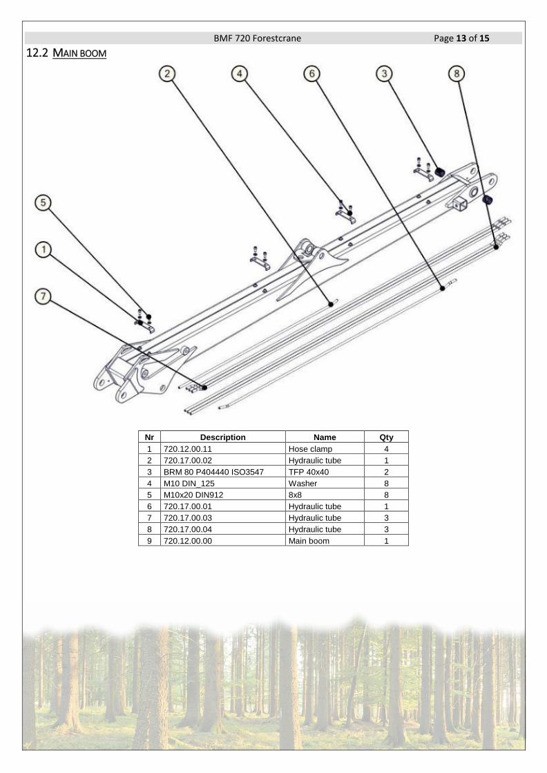
12.2 MAIN BOOM
Nr Description Name Qty
1 720.12.00.11 Hose clamp 4
2 720.17.00.02 Hydraulic tube 1
3 BRM 80 P404440 ISO3547 TFP 40x40 2
4 M10 DIN_125 Washer 8
5 M10x20 DIN912 8x8 8
6 720.17.00.01 Hydraulic tube 1
7 720.17.00.03 Hydraulic tube 3
8 720.17.00.04 Hydraulic tube 3
9 720.12.00.00 Main boom 1

BMF 720 Forestcrane Page 14 of 15
12.3 EXTENSION BOOM
Nr Description Name Qty
1 720.13.01.00 Hose cover 1
2 BRM 80 P404450 ISO3547 TFP 40x50 2
3 720.13.00.13 Slider 1 2
5 720.13.00.14 Slider 2 2
6 720.17.00.05 Hydraulic tube 4
7 720.13.00.18 Slider cap 1
8 720.13.00.18 Slider cap 1
9 720.13.00.16-P1 Hose clamp 1
10 M10 DIN985 Nylock nut 2
11 M10 DIN_125 Washer 11
12 M10x20 DIN912 8x8 10
13 M10x35 DIN912 8x8 2
14 M5 DIN985 Nylock nut 2
15 M5x65 DIN912 8x8 2
16 M8 DIN Nylock nut 12
17 M8x20 DIN912 8x8 8
BMF 720 Forestcrane Page 15 of 15
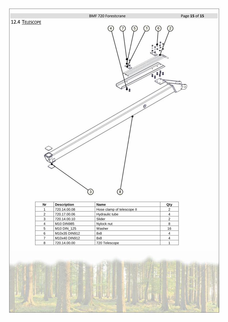
12.4 TELESCOPE
Nr Description Name Qty
1 720.14.00.08 Hose clamp of telescope II 2
2 720.17.00.06 Hydraulic tube 4
3 720.14.00.10 Slider 2
4 M10 DIN985 Nylock nut 8
5 M10 DIN_125 Washer 16
6 M10x35 DIN912 8x8 4
7 M10x40 DIN912 8x8 4
8 720.14.00.00 720 Telescope 1