Embed Size (px)
Citation preview

User Guide
NCT480IP DSLAM
NCT480 IP DSLAM User Guide YML856 Rev3� www.netcomm.com.au
Safety and Precaution
Installation• Use only the type of power source indicated on the marking labels.• Use only power adapter supplied with the product.• Do not overload wall outlet or extension cords as this may increase the risk of electric shock or fire. If the power cord is frayed, replace it with a new one.• Proper ventilation is necessary to prevent the product overheating. Do not block or cover the slots and openings on the device, which are intended for
ventilation and proper operation. It is recommended to mount the product with a stack.• Do not place the product near any source of heat or expose it to direct sunlight. • Do not expose the product to moisture. Never spill any liquid on the product.• Do not attempt to connect with any computer accessory or electronic product without instructions from qualified service personnel. This may result in
risk of electronic shock or fire.• Do not place this product on unstable stand or table.
When in Use• Power off and unplug this product from the wall outlet when it is not in use or before cleaning. Pay attention to the temperature of the power adapter.
The temperature might be high.• After powering off the product, power on the product at least 15 seconds later.• Do not block the ventilating openings of this product.• When the product is expected to be not in use for a period of time, unplug the power cord of the product to prevent it from the damage of storm or
sudden increases in rating.
ServiceDo not attempt to disassemble or open covers of this unit by yourself. Nor should you attempt to service the product yourself, which may void the user’s authority to operate it. Contact qualified service personnel under the following conditions:
• If the power cord or plug is damaged or frayed.• If liquid has been spilled into the product.• If the product has been exposed to rain or water.• If the product does not operate normally when the operating instructions are followed.• If the product has been dropped or the cabinet has been damaged.• If the product exhibits a distinct change in performance.
Caution• Any changes or modifications not expressly approved by the party responsible for compliance could void the authority to operate equipment.
Copyright Notice* �005 All rights reserved. No part of this document may be reproduced or transmitted in any form or by any means, electronic or mechanical, for any
purpose, without the express written permission of the seller.
Disclaimer Information in this document is subject to change without notice. The statements, configurations, technical data, and recommendations in this
document are believed to be accurate and reliable, but are presented without express or implied warranty. The seller therefore assumes no responsibility and shall have no liability of any kind arising from the supply or use of this document or the material contained herein.
Statement of Conditions In the interest of improving internal design, operational function, and/or reliability, the seller reserves the right to make changes to the products
described in this document without notice. The seller does not assume any liability that may occur due to the use or application of the product(s) or circuit layout(s) described herein. In addition, the program and information contained herein are licensed only pursuant to a license agreement that contains restrictions on use and
disclosure (that may incorporate by reference certain limitations and notices imposed by third parties).
Trademarks All other product or service names mentioned in this document may be trademarks of the companies with which they are associated.

YML856 Rev3 NCT480 IP DSLAM User GuideNCT480 IP DSLAM User Guidewww.netcomm.com.au 3
Contents
System Installation Guide .............................................................................................................................4
Web Management Operation Guide ............................................................................................................34
System Configuration Guide .......................................................................................................................90
Appendix A – Abbreviations and Acronyms ..............................................................................................155
Appendix B – System Connector Pin-Outs................................................................................................157RJ-21 xDSL Connector Port Mapping ....................................................................................................157Standard Telco Color Chart ....................................................................................................................159RJ-45 Management Ethernet Connector Pin-Outs ..................................................................................160Local Console Connector Pin-Outs .........................................................................................................161
Appendix C – Legal and Regulatory Information ......................................................................................162

NCT480 IP DSLAM User Guide YML856 Rev34 www.netcomm.com.au
System Installation Guide
Chapter 1 – Preface ......................................................................................................................................1Purpose ...................................................................................................................................................1Organization .............................................................................................................................................1Conventions .............................................................................................................................................1
Chapter 2 – Product Overview ......................................................................................................................3Introduction to the NCT480 .......................................................................................................................3
Features ............................................................................................................................................4Field Applications ...............................................................................................................................5Service Applications ...........................................................................................................................6
NCT480 System Overview.........................................................................................................................8Front View .........................................................................................................................................8Rear View ........................................................................................................................................10Side View ........................................................................................................................................10Alarm I/O Module .............................................................................................................................10
System Management ..............................................................................................................................10Chapter 3 – Preparing for Installation ........................................................................................................13
Safety Requirements...............................................................................................................................13Safety Guidelines .............................................................................................................................13Preventing Electrostatic Discharge Damage .......................................................................................16General Maintenance Guidelines .......................................................................................................16
Site Requirements ..................................................................................................................................17Environmental Requirements ............................................................................................................17Power .............................................................................................................................................18Cabling ...........................................................................................................................................19Rack Mounting ................................................................................................................................19
Tools and Equipment Required ................................................................................................................20Unpacking the NCT480 System ...............................................................................................................20Verifying Contents ..................................................................................................................................21Inspecting for Damage ............................................................................................................................21
Chapter 4 – Installing the NCT480 ..............................................................................................................23
Installation Checklist ..................................................................................................................................23
NCT480 System Installation Procedures ....................................................................................................23Measure Rack Space ..............................................................................................................................23Install the NCT480 Box Chassis ...............................................................................................................24Connecting a Console .............................................................................................................................24Connecting the RJ-21 Subscriber Line Interface .......................................................................................25Connecting the RJ-45 Network Uplink Interface ........................................................................................27Attach and Apply Power ..........................................................................................................................28Attach the Earth Ground ..........................................................................................................................29
Chapter 5 – System Specifications .............................................................................................................30Hardware Specification ...........................................................................................................................30Software Specification ............................................................................................................................32

YML856 Rev3 NCT480 IP DSLAM User GuideNCT480 IP DSLAM User Guidewww.netcomm.com.au 5
ChAPTeR 1 PRefACeThis preface discusses the following topic:
• Purpose
• Organization
• Conventions
PurposeThe purpose of this guide is to provide detailed information and description of NCT480 IP-DSLAM, which includes both software and hardware architecture and other specific features.
OrganizationThis guide contains the following information:
• Preface
• Product Overview
• Preparing for Installation
• Installing the NCT480
• Appendix
ConventionsThis section describes the conventions used in this guide.
Text in this style indicates a NOTICE. A note contains helpful suggestions or reference relay on the topical subjects.
Text in this style indicates a TIP. Performing the information described in the paragraph will help you solve a problem. The tip information might not be troubleshooting or even an action, but could be useful information.
Text in this style indicates a CAUTION. In this situation, you might do something that could result in equipment damage or loss of data.
Text in this style indicates a DANGER. You are in situation that could cause bodily injury. Before you work on any equipment, you must be aware of the hazards involved with electrical circuitry and be familiar with standard practices for preventing accidents.
NE/NEs mentions in this document mean NCT480 IP-DSLAM.

NCT480 IP DSLAM User Guide YML856 Rev36 www.netcomm.com.au
ChAPTeR 2 PRODUCT OveRvIeWThis chapter provides an overview of the NCT480 IP-DSALM (Digital Subscriber line Access Multiplexer) and the service application overview. This chapter contains the following sections:
• Introduction to the NCT480
• NCT480 System Overview
• System Management
Introduction to the NCT480NCT480 mini IP-DSLAM is a revolutionary product with capabilities to interface directly with evolving IP network in a cost effective manner. The Gigabit Ethernet Network uplink interfaces on the NCT480 IP-DSLAM can directly connect to an Internet router or LAN Switch.
The NCT480 comes in compact size (1 U high) and can be used as desktop unit or can be mounted on the rack. It can be fitted on rack with 19 inches in width and 23 inches in depth through the optional rack mount-kit.
The NCT480 is an advanced IP based DSLAM that can be used by service providers to offer broadband multi-service features on the last mile access network on copper based local loop, it offers ADSL, ADSL2, and ADSL2+ interfaces and delivers advanced IP services that include QoS, multicast, subscriber management. These service features prevent clogging and congestion of the bandwidth available to the users allowing smooth, easy and efficient passage of video, voice and data packets across the networks, which also enables operators to increase their revenues and maximize their profits manifold.
The feature rich design make NCT480 the most economical and suitable solution for next generation broadband access platforms. It provides among other advantages easy maintenance and easy installation, which in turn reduces operating cost and network down time to the service providers.
The NCT480 has 48 ADSL Subscriber ports and Network uplink interfaces consists of 2 pairs of Gigabit Ethernet and mini-BGIC. Using various uplink settings, it is possible to stack the NCT480 units and aggregate multiple units over a common network connection.
NCT480 mini IP DSLAM has a web interface for system management. Remote administration, remote firmware upgrade, system configuration, fault and performance management, system diagnostics and subscriber loop tests can all be performed be the web management interface of the NCT480 IP DSLAM. Please refer to the Web Management Operation Guide in this user manual for further information.

YML856 Rev3 NCT480 IP DSLAM User GuideNCT480 IP DSLAM User Guidewww.netcomm.com.au �
featuresNCT480 mini IP-DSLAM is designed to meet with industry standards in functionality, performance, and reliability. As a compact IP-DSLAM platform, NCT480 can provide ADSL service for 48 users over existing PSTN telephone wiring. More detailed features are listed below:
hardware features:
• Pizza box type supports 48 ADSL ports and build-in POTS splitter equipped available
• Cost effective access solution for always on high-speed Internet service application
• Existing twisted pair telephone line via POTS splitter/Low-Pass-Filter, it means ADSL and telephone services can be provided concurrently
• Support service capacity expansion via units stacking
• Two pair of 10/100/1000 Ethernet and mini-GBIC uplink Network uplink interfaces
• One RS-232 serial console port
• One 10/100 Base T Ethernet management port
• Support non-blocking switching fabric and Wire-speed switching capability
• Alarm input IO interfaces
Software features:
• Local system configuration and management through RS-232 console or the Ethernet management port
• Remote system configuration and management using Telnet or web management through GE network uplink interfaces
• Embedded SNMP v1, v2c management agent with standard MIB-II
• Support TFTP firmware upgrade
• Support HTTP firmware upgrade
• Support Subscriber traffic isolation among ADSL line ports
• Support RFC 2684 bridge mode IPoE multi-protocol over AAL5
• Support RFC 2516 PPPoE packet forwarding
• Support QoS for IEEE 802.1p priority queues
• Support Subscriber rate limiting
• Support ADSL Line Profile and VLAN batch configuration
• Support IEEE 802.1Q VLAN tagging
• Support IEEE 802.1ad VLAN stacking and VLAN translation
• Manually configurable mapping between VLAN tag and ATM PVC
• Support IEEE 802.1D spanning tree bridging between Network uplink interface and any ADSL Subscriber interface
• Support IGMP snooping and Multicast
• Support OAM F5 fault diagnostic
• Support MAC address access control
• Support IP/MAC packet filtering
• Support IEEE 802.3ad link aggregation on Network uplink interface through CLI

NCT480 IP DSLAM User Guide YML856 Rev38 www.netcomm.com.au
field ApplicationsThis section contains the most popular application scenarios for NCT480 IP-DSLAM, and helps operator to understand how to implement and service with it.
Internet Service
With the ADSL CPE connecting to NCT480, IP traffic will be managed and monitored to ensure the connection quality.
NCT480 min-IP DSLAM has ability to transport traffic with a variety of protocols from ADSL CPE or end user PC to service applications such as PPPoE, PPPoA, IPoA, EoA and L2TP, L2F, PPTP, IP-Sec tunneling.
NCT480 IP-DSLAM
Figure �-1 Internet Service Illustrate
virtual Private Network Service
NCT480 can be beneficial for ISP (Internet Service Provider) who is offering VPN (Virtual Private Network) service to corporations. NCT480 can be set up to provide value-add services to residential customers and small-to-medium business by tunneling protocols to upper layer broadband router.
NCT480 IP-DSLAM
Figure �-� Virtual Private Network Service Illustrate
YML856 Rev3 NCT480 IP DSLAM User GuideNCT480 IP DSLAM User Guidewww.netcomm.com.au �
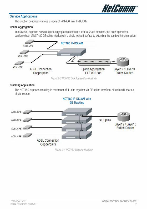
Service ApplicationsThis section describes various usages of NCT480 mini IP-DSLAM.
Uplink Aggregation
The NCT480 supports Network uplink aggregation complied in IEEE 802.3ad standard, this allow operator to configure both of NCT480 GE uplink interfaces in a single logical interface to extending the bandwidth transmission.
NCT480 IP-DSLAM
Figure �-3 NCT480 Link Aggregation Illustrate
Stacking Application
The NCT480 supports stacking in maximum of 4 units together via GE uplink interface, all units will share a single source.
NCT480 IP-DSLAM with Ge Stacking
Figure �-4 NCT480 Stacking Illustrate
NCT480 IP DSLAM User Guide YML856 Rev310 www.netcomm.com.au
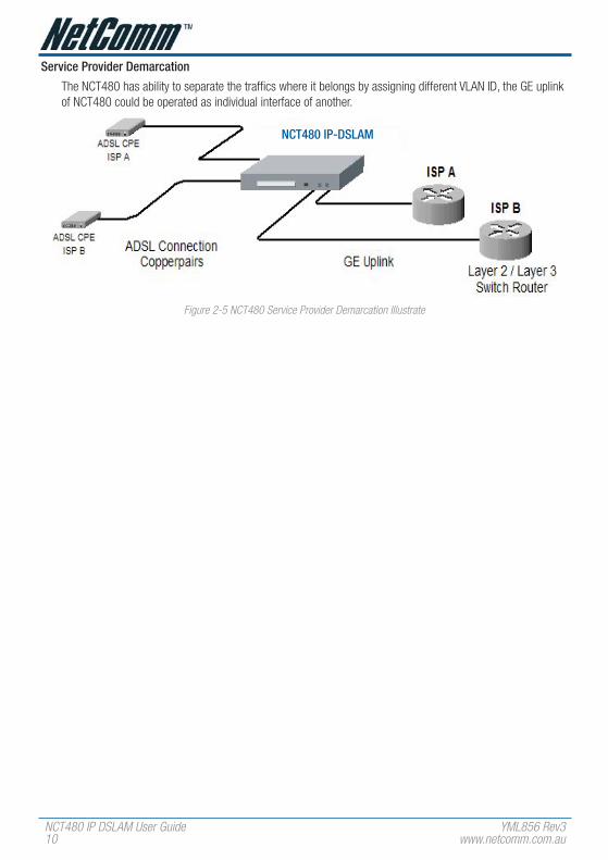
Service Provider Demarcation
The NCT480 has ability to separate the traffics where it belongs by assigning different VLAN ID, the GE uplink of NCT480 could be operated as individual interface of another.
NCT480 IP-DSLAM
Figure �-5 NCT480 Service Provider Demarcation Illustrate

YML856 Rev3 NCT480 IP DSLAM User GuideNCT480 IP DSLAM User Guidewww.netcomm.com.au 11
NCT480 System OverviewNCT480 Series mini IP-DSLAM is built in 1.96 inch (1 U) high, 10.2 inch (26 cm) deep, and 17.7 inch wide (23 inch bracket available) compact design. Pluggable build-in splitter is optional.
front viewThe Figure 2-6 shows the front panel of the NCT480 mini IP-DSLAM.
Figure �-6 NCT480 Front Panel
The Table 2-1 shows the LED status of the NCT480 Series mini IP-DSLAM.
The Table 2-2 shows the front panel connector description of the NCT480 mini IP-DSLAM.
LeD State function
Power LeD
PWD Green solid System power normal
Off System fault
error LeD
error/Debug Green Solid Boot fault or system operate in debug mode
Off System running normal
DSL Status LeD (port 1 ~ port 48)
1 ~ 48 Green solid per port The ADSL link is currently connect
Green blinking Handshaking
Off Link down or port disable
Ge 1 / Ge 2
Orange LeD Orange blinking Interface port is activate
Off Interface port is inactivate
Green LeD Green solid Interface port is link
Off No cable connected, port disabled, or port fault
Table �-1 NCT480 Front Panel LED Status
NCT480 IP DSLAM User Guide YML856 Rev31� www.netcomm.com.au
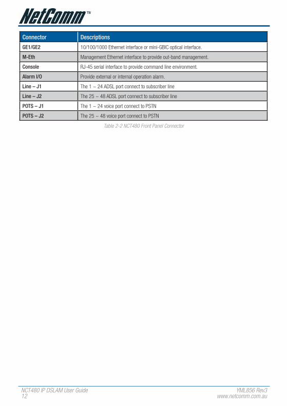
Connector Descriptions
Ge1/Ge2 10/100/1000 Ethernet interface or mini-GBIC optical interface.
M-eth Management Ethernet interface to provide out-band management.
Console RJ-45 serial interface to provide command line environment.
Alarm I/O Provide external or internal operation alarm.
Line – J1 The 1 ~ 24 ADSL port connect to subscriber line
Line – J2 The 25 ~ 48 ADSL port connect to subscriber line
POTS – J1 The 1 ~ 24 voice port connect to PSTN
POTS – J2 The 25 ~ 48 voice port connect to PSTN
Table �-� NCT480 Front Panel Connector

YML856 Rev3 NCT480 IP DSLAM User GuideNCT480 IP DSLAM User Guidewww.netcomm.com.au 13
Rear viewThe Figure 2-7 shows the rear panel of the NCT480 mini IP-DSLAM.
Figure �-� NCT480 Rear View
The equipment has provision for a permanently connected Protective Earthing Conductor.
Side viewThe Figure 2-8 shows the Left-hand Side view of the NCT480 mini IP-DSLAM.
Figure �-8 Left-hand Side View
The Figure 2-9 shows the Right-hand Side view of the NCT480 mini IP-DSLAM.
Figure �-� Right-hand Side View
Alarm I/O ModuleThe Alarm I/O Module contains alarm I/O relay.
Digital I/O Pin Description
Output Pin (for alarm output receptacle)
CO Common pin
NO Circuit with normal open pin
NC Circuit with normal close pin
Input Pin (for alarm input relay)
1 (+), 2 (-) First pair of input signal terminal
3 (+), 4 (-) Second pair of input signal terminal
5 (+), 6 (-) Third pair of input signal terminal
7 (+), 8 (-) Fourth pair of input signal terminal
Table �-3 NCT480 Alarm I/O Relay Pin Description for Hardware revision � face panel
NCT480 IP DSLAM User Guide YML856 Rev314 www.netcomm.com.au
System ManagementOperator can provision and manage the NCT480 IP-DSALM through the following system management mode:
CLI – Command line management
LCT – A complete SNMP basis NMS (Element Management System) provides GUI operation under Client-Server architecture through in-band or out-band IP interface. (This SNMP IP DSLAM management utility is only applicable to NCT480 firmware R1.43 or older)
Web Management Interface – NCT480 mini IP DSLAM has a web interface for system management. Remote administration, remote firmware upgrade, system configuration, fault and performance management, system diagnostics and subscriber loop tests can all be performed be the web management interface of the NCT480 IP DSLAM. Web management is only applicable to NCT480 running firmware R2.0 or later. Web management of NCT480 IP DSLAM is only compatible under Internet Explorer 6.0 environment.
Changes will be subjected to firmware revision in the future)
Local ManagementThe NCT480 provide Ethernet interface for CLI connection at local maintenance and operation. An RJ-45 to DB-9 can be used to connect NCT480 to PC via serial port. The NCT480 can also be locally managed by its inbuilt web interface through management port Eth-3 with factory default IP address of 192.168.1.1/24.
IP Network ManagementThe NCT480 provides out-band management thought management Ethernet interface or its GE interface with proper IP address to associate in the layer 3 network.

YML856 Rev3 NCT480 IP DSLAM User GuideNCT480 IP DSLAM User Guidewww.netcomm.com.au 15
ChAPTeR 3 PRePARING fOR INSTALLATIONThis chapter tells you how to prepare for the installation of the NCT480 mini IP-DSLAM.
The chapter contains the following sections:
• Safety Requirements
• Site Requirements
• Tools and Equipment Required
• Unpacking the NCT480 System
• Verify Contents
• Inspecting for Damage
Safety RequirementsThis section describes safety requirement of NCT480 system. Before you install the NCT480 system, ensure that all the criteria in this section are met. The section describes the following safety requirements:
• Safety Guidelines
• Preventing Electrostatics Discharge Damage
• General Maintenance Guidelines

NCT480 IP DSLAM User Guide YML856 Rev316 www.netcomm.com.au
Safety GuidelinesBefore working on the equipment, be aware of standard safety guidelines and the hazards that are involved in working it electrical circuitry to prevent accidents. Adhere to the following cautions and warnings and those throughout the guide for safe and hazard-free installation.
Only trained and qualified personnel should be allowed to install or replace this equipment.
Before removing the equipment, disconnect the telephone-network cables to avoid contact with telephone-network voltages.
Do not work on system or connect or disconnect cables during periods of lightning activity.
Avoid using a telephone (other than a cordless type) during an electrical storm. There may be a remote risk of electric shock from lightning.
Read the power instructions before you connect the system to its power source.
For safety reason, the ground wire must connect to safety (earth) ground at supply side of the AC wiring; ensure that the host is connected to earth ground during the normal use.
To reduce the risk of electric shock when servicing any individual unit, disconnect the power cord or cords that connect the unit to the AC power strip or DC bus bar.
Two people are required to lift the box. Grasp the box underneath the lower edge and lift with both hands. To prevent injury, keep your back straight and lift with your legs, not your back.
To prevent bodily injury when mounting or servicing this unit in a rack, you must take special precautions to ensure that the system remains stable. The following guidelines are provided to ensure your safety:
• When mounting this unit in a partially filled rack, load the rack from the bottom to the top with the heaviest component at the bottom of the rack
• If the rack is provided with stabilizing devices, install the stabilizers before mounting or servicing the unit in the rack
Ethernet cable must be shielded when used in a central office environment.
This unit is intended for installation in restricted access areas, A restricted access area is where access can only be gained by service personnel through the use of a special tool, lock and key, or other means of security, and is controlled by the authority responsible for the location.
To reduce the risk of fire, use only No. 36 AWG or larger telecommunication line cord.
Use copper conductors only.
Never touch un-insulated telephone wires or terminals unless the telephone line has been disconnected at the network interface.
Use caution when installing or modifying telephone lines.
Before working on equipment that is connected to power lines, remove jewelry (including rings, necklaces, and watches). Metal objects will heat up when connected to power and ground and can cause serious burns or weld the metal object to the terminals.
To avoid electric shock, do not connect safety extra-low voltage (SELV) circuits to telephone-network voltage (TNV) circuits. LAN ports contain SELV circuits and WAN ports contain TNV circuits. Some LAN and WAN ports both use RJ-45 connectors. Use caution when connecting cables.
Ultimate disposal of this product should be handled according to all national laws and regulations.
Do not use this product near water; for example, near bath tub, wash bowl, kitchen sink or laundry tub, in a wet basement, or near a swimming pool.
Do not use this product near water; for example, near bath tub, wash bowl, kitchen sink or laundry tub, in a wet basement, or near a swimming pool.
Never install telephone RJ-�1 connector in wet locations unless the connector is specifically designed for wet locations.
Do not use a telephone to report a gas leak in the vicinity of the leak.

YML856 Rev3 NCT480 IP DSLAM User GuideNCT480 IP DSLAM User Guidewww.netcomm.com.au 1�
Preventing electrostatic Discharge DamageElectrostatic discharge (ESD) is a transfer of electrostatic charge between bodies of different electrostatic potentials, such as an operator and a piece of electrical equipment. It occurs when electronic components are improperly handled, and it can damage equipment and impair electrical circuitry. Electrostatic discharge is more likely to occur with the combination of synthetic fibers and dry atmosphere.
Use an antistatic strap during removing and replacing NCT480 units.
Always use an ESD ankle or wrist strap and ensure that it makes good skin contact.
To properly guard against ESD damage and shocks, the wrist strap and cord must operate effectively.
Do not touch any exposed contact pins or connector shells of interface ports that do not have a cable attached. If cables are connected at one end only, do not touch the exposed pins at the unconnected end of the cable.
This equipment is intended for use in residential and commercial environments only.
Periodically check the resistance value of the antistatic strap, which should be between 1 and 10 megohms (Mohms).
General Maintenance GuidelinesThe following maintenance guidelines apply to NCT480 system units:
Keep the NCT480 box area clear and dust-free during and after installation.
If you remove the chassis cover for any reason, store it in a safe place.
Do not perform any action that creates a hazard to people or makes equipment unsafe.
Keep walk areas clear to prevent falls or damage to equipment.
NCT480 IP DSLAM User Guide YML856 Rev318 www.netcomm.com.au
Site RequirementsThis section describes requirements for the site in which the NCT480 system is to be installed. Before you install the NCT480 system, ensure that all the criteria in this section are met. The section describes the following:
• Environmental Requirements
• Power
• Cabling
• Rack Mounting
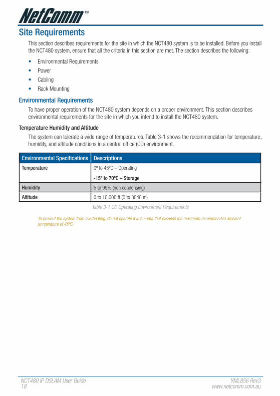
environmental RequirementsTo have proper operation of the NCT480 system depends on a proper environment. This section describes environmental requirements for the site in which you intend to install the NCT480 system.
Temperature humidity and Altitude
The system can tolerate a wide range of temperatures. Table 3-1 shows the recommendation for temperature, humidity, and altitude conditions in a central office (CO) environment.
environmental Specifications Descriptions
Temperature 0º to 45ºC – Operating
-15º to 70ºC – Storage
humidity 5 to 95% (non condensing)
Altitude 0 to 10,000 ft (0 to 3048 m)
Table 3-1 CO Operating Environment Requirements
To prevent the system from overheating, do not operate it in an area that exceeds the maximum recommended ambient temperature of 45ºC.
YML856 Rev3 NCT480 IP DSLAM User GuideNCT480 IP DSLAM User Guidewww.netcomm.com.au 1�
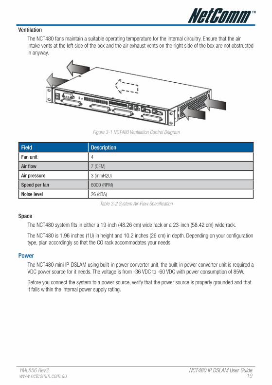
ventilation
The NCT480 fans maintain a suitable operating temperature for the internal circuitry. Ensure that the air intake vents at the left side of the box and the air exhaust vents on the right side of the box are not obstructed in anyway.
Figure 3-1 NCT480 Ventilation Control Diagram
field Description
fan unit 4
Air flow 7 (CFM)
Air pressure 3 (mmH20)
Speed per fan 6000 (RPM)
Noise level 26 (dBA)
Table 3-� System Air-Flow Specification
Space
The NCT480 system fits in either a 19-inch (48.26 cm) wide rack or a 23-inch (58.42 cm) wide rack.
The NCT480 is 1.96 inches (1U) in height and 10.2 inches (26 cm) in depth. Depending on your configuration type, plan accordingly so that the CO rack accommodates your needs.
PowerThe NCT480 mini IP-DSLAM using built-in power converter unit, the built-in power converter unit is required a VDC power source for it needs. The voltage is from -36 VDC to -60 VDC with power consumption of 85W.
Before you connect the system to a power source, verify that the power source is properly grounded and that it falls within the internal power supply rating.

NCT480 IP DSLAM User Guide YML856 Rev3�0 www.netcomm.com.au
CablingFor detailed information on the required cables, refer to “Appendix System Connector Pin-Outs”.
NCT480 Cabling
The Figure 2-2 illustrates the NCT480 system cabling.
Figure 3-� NCT480 Cabling Diagram
Rack MountingMount your NCT480 system in a rack is highly recommend. Ensure that vertical rivet spacing on the rack rails meets standard EIA-310-C or ETS300 requirements.
NCT480 fits into a 19 inch wide rack or an ETSI 600 mm wide (23 inch) cabinet by replacing the ear bracket.
Figure 3-3 NCT480 Mounting Diagram.

YML856 Rev3 NCT480 IP DSLAM User GuideNCT480 IP DSLAM User Guidewww.netcomm.com.au �1
Tools and equipment RequiredThe Table 3-3 lists the tools and equipment you need to install and remove the NCT480 system components.
Check Tools and equipment
hardware Components
NCT480 System
DC Power Supply
RJ-45 to DB-9 RS232 Console Cable
RJ-21 DSLAM Cables
Software Components
LCT DSLAM Management Utility
(Only Applicable to NCT480 running firmware R1.43 or older; NCT480 running R2.0 or newer uses web management interface for system management.)
Tools
A 3/16 inch flat-head screwdriver
A Phillips-head screwdriver
Necessary equipment for ESD protection
Mounting screw – To mount the NCT480 system to the rack
Tie wraps
Table 3-3 Installation Tools Lists

NCT480 IP DSLAM User Guide YML856 Rev3�� www.netcomm.com.au
Unpacking the NCT480 SystemEach NCT480 system units is securely packaged in a shipping box.
To unpack the NCT480 units, complete the following steps:
1 Inspect the packing containers.If any damage or other signs of mishandling are evident, inform both the local freight carrier and Turbo Networks before unpacking. Your freight carrier can provide you with the procedures necessary to file a claim for damages.
2 Carefully open the box.
3 Remove all packing material.
4 Remove the unit form the box.
5 Open the accessory kits and boxes that contain the cables, documentation, and management software. Do not use a knife to open these boxes.
verifying ContentsTo verify that your shipment is complete, make sure that you received everything on your packing list, and then compare your packing list to your order. If any items are missing or you need additional information, contact your local supporter.
Inspecting for DamageAfter you verify that all of the equipment is included, carefully examine the assemblies, units and cables for any damage resulting from shipping. If you suspect any damage form shipping, contact your local freight carrier for procedures on damage claims.
If you observe any physical defects in the items you ordered, obtain standard warranty service by delivering the defective part to your local supporter during the applicable warranty period.
YML856 Rev3 NCT480 IP DSLAM User GuideNCT480 IP DSLAM User Guidewww.netcomm.com.au �3
ChAPTeR 4 INSTALLING The NCT480This chapter describes how to install the NCT480 mini IP-DSLAM.
This chapter contains the following sections:
• Installation Checklist
• NCT480 System Installation Procedures
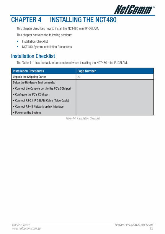
Installation ChecklistThe Table 4-1 lists the task to be completed when installing the NCT480 mini IP-DSLAM.
Installation Procedures Page Number
Unpack the Shipping Carton 20
Setup the hardware environments:
• Connect the Console port to the PC’s COM port
• Configure the PC’s COM port
• Connect RJ-21 IP DSLAM Cable (Telco Cable)
• Connect RJ-45 Network uplink Interface
• Power on the System
Table 4-1 Installation Checklist
NCT480 IP DSLAM User Guide YML856 Rev3�4 www.netcomm.com.au
NCT480 System Installation ProceduresThis section describes procedures for the site in which the NCT480 system is to be installed.
The section describes the following:
• Measure Rack Space
• Install the NCT480 Box Chassis
• Connecting a Console
• Connecting the RJ-21 Subscriber Line Interface
• Connecting the RJ-45 Network Uplink Interface
• Attach and Apply Power
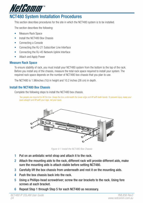
Measure Rack SpaceTo ensure stability of rack, you must install your NCT480 system from the bottom to the top of the rack. Before you install any of the chassis, measure the total rack space required to install your system. The required rack space depends on the number of NCT480 box chassis that you plan to use.
The NCT480 is 1.96inches (1U) in height and 10.2 inches (26 cm) in depth.
Install the NCT480 Box ChassisComplete the following steps to install the NCT480 box chassis.
Two people are required to lift the box. Grasp the box underneath the lower edge and lift with both hands. To prevent injury, keep your back straight and lift with your legs, not your back.
Figure 4-1 Install the NCT480 Box Chassis
1 Put on an antistatic wrist strap and attach it to the rack.
2 Attach the mounting aids to the rack, different rack will provide different aids, make sure the mounting aids is attach stable before setting NCT480.
3 Carefully lift the box chassis from underneath and rest it on the mounting aids.
4 Push the box chassis back into the rack.
5 Using a Phillips-head screwdriver; screw the ear brackets to the rack. Using fore screws at each bracket.
6 Repeat Step 1 through Step 5 for each NCT480 as necessary.

YML856 Rev3 NCT480 IP DSLAM User GuideNCT480 IP DSLAM User Guidewww.netcomm.com.au �5
Connecting a ConsoleComplete the following steps to connect the NCT480 Console management.
1 Connect the RJ-45 to DB-9 adapter cable to the Console port on the NCT480.
2 Connect the other end (female) to the computer’s COM port.
Figure 4-� RJ-45 to DB-�-female Adapter cable for Console Management
Figure 4-3 NCT480 Console Port Management Cabling
Configure the PC’s COM port
Use your terminal emulation program (such as HyperTerminal in Windows) to set your COM protocol to the following settings:
Parameter Setting
Baud rate 9600
Data bits 8
Parity None
Start bits 1
Stop bits 1
flow control None
Table 4-� NCT480 Console Management Setting

NCT480 IP DSLAM User Guide YML856 Rev3�6 www.netcomm.com.au
Connecting the RJ-21 Subscriber Line InterfaceNCT480 RJ-21 Telco Cable Connecting
Complete the following steps to connect the RJ-21 connector
Figure 4-4 Rear Panel RJ-�1 Connector Cabling for NCT480
1 Attach the RJ-21 champ cable to connect the NCT480 to the Subscriber MDf corresponding DSL bus sockets.
2 Attach the RJ-21 champ cable to connect the NCT480 to the PSTN MDf where the socket with “POTS” labels.
2 Screw tight the RJ-21 champ with connect socket, make sure the connection is tight enough due to cabling.
3 Repeat Step 1 through Step 2 for each RJ-21 socket as necessary.

YML856 Rev3 NCT480 IP DSLAM User GuideNCT480 IP DSLAM User Guidewww.netcomm.com.au ��
Connecting the RJ-45 Network Uplink InterfaceComplete the following steps to connect the RJ-45 network uplink.
To ensure the 1000 Base-T performance, please using the standard Category 5, 6, � Ethernet UTP cable.
Figure 4-5 Front Panel RJ-45 Network Uplink Cabling for NCT480
1 Connect one end of the RJ-45 to the “Gige 1” or “Gige 2” port on the NCT480 front panel.
2 Connect the other end of RJ-45 to the Layer 2 / Layer 3 switch router of provider’s IP network.
Figure 4-6 Front Panel mini-GBIC Network Uplink Cabling for NCT480

NCT480 IP DSLAM User Guide YML856 Rev3�8 www.netcomm.com.au
Attach and Apply PowerComplete the instruction to connect the DC power cord to NCT480.
Figure 4-� Front Panel AC Power Connection for NCT480
1 ensure the power switch is set to the off position.
2 Use the Philip-head screwdriver to turn the screws on the terminal block counterclockwise to losses the terminal connectors, GND (positive), -48vDC (negative), and ground.
3 Remove the PvC wrapping of the wire to be connected to the terminal block
4 Insert the end of the wire into the corresponded receptacle with the terminal block behind the screws. They must be fully inserted into the terminal block, so that no bare wire is exposed.
5 Tighten the screws and pull on the wire to verify that it is held firmly in place.
6 If you are connecting a second power source, repeat Step 2 to Step 5 for the second block.
7 Turn on the power switch and visually check that the Power LeD at front panel is On.The input voltage tolerance limits for DC power are -36 to -60 VDC.

YML856 Rev3 NCT480 IP DSLAM User GuideNCT480 IP DSLAM User Guidewww.netcomm.com.au ��
Attach the earth Ground
Complete the instruction to connect the grounding cord of NCT480.
Figure 4-8 Earth Ground of NCT480
1 ensure the power switch is set to the off position.
2 Use the Philip-head screwdriver to turn the screws on the earth ground screw point.
3 Strip one end of the ground wire to the ground hole of system
4 Connect the other end of the ground wire to a suitable grounding point at your site.The equipment has provision for a permanently connected Protective Earthing Conductor.

NCT480 IP DSLAM User Guide YML856 Rev330 www.netcomm.com.au
ChAPTeR 5 SySTeM SPeCIfICATIONSThe chapter provides the detail descriptions of technical specification of NCT480 in hardware and software, respectively. This chapter contains the following sections:
• Hardware Specification
• Software Specification
hardware SpecificationThis section shows the system hardware specification of the NCT480 mini IP-DSLAM.
Table 5-1 lists the hardware specifications of NCT480 system.
Specification Description
Dimensions 2” x 19” or 23” x 11” (H x W x D)
Weight With Splitter: 4 Kg
Console interface Management access
RJ-45 to RS-232 Female DB-9 adaptor cable
Gigabit Ethernet out-band management
Power requirements 85Walt; -36VDC ~ -60VDC; ~2 Amp.
Front Panel Interfaces 2 x RJ-45 Gigabit Ethernet interface (10/100/1000 Base-T)
2 x mini-GBIC Optical interface (Alternative)
1 x 10/100 Base-T Management Port
1 x RS-232 Console Port
1 x Alarm I/O socket
2 x Telco-50P Female connectors for POTS
2x Telco-50P Female conenctors for Lines
Dual DC power source terminal
ADSL Subscriber interface 48 ports
ADSL Standards support ANSI T1.413
ITU-T G.992.1, (G.dmt) Annex A
ITU-T G.992.2, (G.lite) Annex A
ITU-T G.992.3 (ADSL2) Annex A, AnnexL
ITU-T G.992.5 (ADSL2+) Annex A, AnnexM
ATM Protocol Ethernet over ATM (RFC 1483 bridge)
IPoA (RFC 1483 route)
PPPoA (RFC 2364)
PPPoE (RFC 2516)

YML856 Rev3 NCT480 IP DSLAM User GuideNCT480 IP DSLAM User Guidewww.netcomm.com.au 31
Specification Description
CO operating requirements Temperature:
32º to 149ºF (0º to 65ºC) – Operating
23º to 149ºF (-5º to 65ºC) – Short-term operating
5º to 158ºF (-15º to 70ºC) – Storage
Humidity:
5 to 95% (non condensing)
Safety Certification CE
FCC part 68
FCC part 15
IEC 60950
EN60950
AS/NZS 60950
BS EN60950
SS EN60950
CAN/CSA C22.2 No.60950
UL60950
EN55022
Table 5-1 NCT480 System Specification

NCT480 IP DSLAM User Guide YML856 Rev33� www.netcomm.com.au
Software SpecificationTable 5-2 lists the software specification of NCT480.
Specification Description
System Control Alarm Status Surveillance
• Automatic alarm and status report
• LED indication for system status
Performance Monitoring
• Line rate
• RFC 2662/RFC 3440 compliant ADSL line performance parameters gathering
Configuration
• Support add, delete, query, and modify functions for configuration
• IGMP snooping setting
• VLAN setting
• STP/RSTP setting
• ADSL Subscriber line management per profile setting
• System firmware upgrade through Web Interface and/or download through TFTP
• BOOTP/DHCP client
Security
• Support security and multiple level login
vLAN • Support IEEE 802.1Q VLAN Tagging, Port-based VLAN, and GVRP
• Support 512 VLANs concurrently
• Support IEEE 802.1ad VLAN stacking and VLAN translation
Link Aggregation Support 802.3ad static and dynamic link aggregation
QoS • Support IEEE 802.1p with 4-priority queues
• DiffServ support
• Pack classification basis on MAC/IP addresses and TCP/UDP port number
Multicast • Support IGMP snooping on IGMPv1, IGMP v2 and IGMP v3 membership
• Up to 256 Multicast Groups and 256 copies for each Multicast Group
• Broadcast storm control
Bridging • 4 K MAC addresses
• MAC, IP, TCP/UDP port addresses filtering
OAM and Access Control • ADSL Subscriber MAC address number limiting
• DHCP Relay Agent with option 82

YML856 Rev3 NCT480 IP DSLAM User GuideNCT480 IP DSLAM User Guidewww.netcomm.com.au 33
Specification Description
Network Management • CLI through console and Telnet
• SNMP manageable by NMS (Planned)
• Web management
• Provide configuration, fault, performance, security management
Management MIB • RFC 1157 SNMP v1
• SNMP v2c
• RFC 1213 MIB-II
• RFC 1493 Bridge MIB
• RFC 2233 IF-MIB
• RFC 2515 ATM MIB
• RFC 2674 802.1Q MIB
• RFC 2622 / RFC 3440 ADSL line MIB
• Enterprise NCT480 MIB
Table 5-� NCT480 Software and Management Specification

NCT480 IP DSLAM User Guide YML856 Rev334 www.netcomm.com.au
Web Management Operation Guide
Preface .......................................................................................................................................................36Purpose .................................................................................................................................................36Organization ...........................................................................................................................................36Conventions ...........................................................................................................................................36
Chapter 1 – Getting Started Web Management ..........................................................................................37Login Window ........................................................................................................................................37Operation Window Overview ....................................................................................................................38
Chapter 2 – System Menu ..........................................................................................................................39General Information ................................................................................................................................40Statistics Information ..............................................................................................................................41User and Password .................................................................................................................................42Bridge Mode ..........................................................................................................................................43Backup and Restore ...............................................................................................................................45
Backup Configuration .......................................................................................................................45Restore Configuration .......................................................................................................................45
Firmware Upgrade ..................................................................................................................................46Commit and Reboot ................................................................................................................................47
Commit Configuration ......................................................................................................................47Reboot System ................................................................................................................................47Restore Factory Configuration ...........................................................................................................48
Chapter 3 – Status and Performance .........................................................................................................49DSL Status .............................................................................................................................................50Layer Information ...................................................................................................................................51Ethernet Statistics ..................................................................................................................................52PVC Statistics .........................................................................................................................................53Line 15min Performance ........................................................................................................................53Line 1day Performance ...........................................................................................................................54Alarm I/O Status .....................................................................................................................................54
Chapter 4 – Deployment Menu ...................................................................................................................55DSL Port ................................................................................................................................................55DSL Profile Configuration ........................................................................................................................56
Add DSL Profile ...............................................................................................................................57DSL Profile Mapping ...............................................................................................................................59DSL Alarm Profile ...................................................................................................................................61Power Management Mode ......................................................................................................................63PVC Setting ............................................................................................................................................64
Add Port & PVC ...............................................................................................................................66Set PPPoA MAC ...............................................................................................................................68
Route Setting .........................................................................................................................................69Ethernet Setting .....................................................................................................................................70
Add Ethernet Interface ......................................................................................................................72SNMP Host ............................................................................................................................................73SNMP Community ..................................................................................................................................74Alarm I/O Control ....................................................................................................................................75

YML856 Rev3 NCT480 IP DSLAM User GuideNCT480 IP DSLAM User Guidewww.netcomm.com.au 35
Chapter 5 – Access Control ........................................................................................................................76MAC Limit ..............................................................................................................................................76Port ACL ................................................................................................................................................77Global ACL .............................................................................................................................................78
Chapter 6 – Protocol Menu .........................................................................................................................79VLAN Port ..............................................................................................................................................79Trunk VLAN Setting .................................................................................................................................80
Add Trunk VLAN ...............................................................................................................................81VLAN Mode Setting ..........................................................................................................................82
IGMP Snooping ......................................................................................................................................84DHCP & PPPoE Relay ..............................................................................................................................85Spanning Tree Protocol ...........................................................................................................................86Rapid Spanning Tree Protocol ..................................................................................................................87
Chapter 7 – Diagnostic Menu .....................................................................................................................89DSL Bin Information ................................................................................................................................89ATM OAM Test .......................................................................................................................................90ADSL2 DELT Test ....................................................................................................................................91
NCT480 IP DSLAM User Guide YML856 Rev336 www.netcomm.com.au
PRefACeThis preface discusses the following topic:
• Purpose
• Organization
• Conventions
PurposeThe purpose of this guide is to provide detailed information and description of NCT480 IP-DSLAM web management, which includes web interface configuration and other specific features.
OrganizationThis guide contains the following information:
• Preface
• Getting Started the NCT480 Web Management
• NCT480 Web Management Menus
• Appendix
ConventionsThis publication uses the document conventions listed in this section.
NE/NEs mention in this document means NCT480 IP-DSLAM
CLI Ex – Command line management with a local console or Telnet through in-band or out-band IP interface for CIT (Craft Interface Terminal) connection.
Text in this style indicates a NOTICE. A note contains helpful suggestions or reference relay on the topical subjects.
Text in this style indicates a TIP. Performing the information described in the paragraph will help you solve a problem. The tip information might not be troubleshooting or even an action, but could be useful information.
Text in this style indicates a CAUTION. In this situation, you might do something that could result in equipment damage or loss of data.
Text in this style indicates a DANGER. You are in situation that could cause bodily injury. Before you work on any equipment, you must be aware of the hazards involved with electrical circuitry and be familiar with standard practices for preventing accidents.

YML856 Rev3 NCT480 IP DSLAM User GuideNCT480 IP DSLAM User Guidewww.netcomm.com.au 3�
ChAPTeR 1 GeTTING STARTeD WeB MANAGeMeNTThis chapter provides the descriptions to start the web management in your network.
This chapter contains the following sections:
• Login Window
• Operation Window Overview
Login WindowLaunch your web browser, and go to http://196.168.1.1 The following screen appears.
The login window to use User name/Password = admin/admin then click “login” button to login.
Figure 1-1 NCT480 Web Management Login Window
Even though you can connect to the IP-DSLAM Eth1 (uplink) or Eth� (downlink), it is recommended that you connect your computer to management port for initial configuration.
The NCT480 web management login User name/Password = admin/admin of default value.
NCT480 IP DSLAM User Guide YML856 Rev338 www.netcomm.com.au
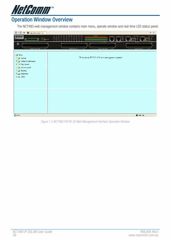
Operation Window OverviewThe NCT480 web management window contains main menu, operate window and real-time LED status panel.
Figure 1-� NCT480 FW R�.3� Web Management Interface Operation Window

YML856 Rev3 NCT480 IP DSLAM User GuideNCT480 IP DSLAM User Guidewww.netcomm.com.au 3�
ChAPTeR 2 SySTeM MeNUThis chapter provides the detail system menu that contains data information of web managed agent (NCT480). This chapter contains the following sections:
• General Information
• Statistics Information
• User and Password
• Bridge Mode
• Backup and Restore
• Firmware Upgrade
• Commit and Reboot

NCT480 IP DSLAM User Guide YML856 Rev340 www.netcomm.com.au
General InformationYou can edit the system information in this dialog.
Figure �-1 System General Information Dialog
Table 2-1 describes the general information dialog field items.
Item Description
System Description This is a text description of the entity.
System Up Time (hh:MM:SS) This shows the time in seconds since the system is up.
System Contact with us This specifies the textual identification of the contact person for this managed node, together with the information on how to contact this person.
Valid values: String of up to 100 characters (‘A’ – ‘Z’, ‘a’ – ‘z’, ‘0’ – ‘9’, ‘-’, ‘_’) and any combination of printable characters excluding ‘;’.
System administratively-assigned name
This specifies administrator-specific information.
Valid values: String of up to 100 characters (‘A’ – ‘Z’, ‘a’ – ‘z’, ‘0’ – ‘9’, ‘-’, ‘_’) and any combination of printable characters excluding ‘;’.
System Location This specifies the physical location of this node.
Valid values: String of up to 100 characters (‘A’ – ‘Z’, ‘a’ – ‘z’, ‘0’ – ‘9’, ‘-’, ‘_’) and any combination of printable characters excluding ‘;’.
System vendor Information This indicates the vendor-specific information.
Valid values: String of up to 100 characters (‘A’ – ‘Z’, ‘a’ – ‘z’, ‘0’ – ‘9’, ‘-’, ‘_’) and any combination of printable characters excluding ‘;’.
hardware version This indicates the hardware and firmware information.
version of the control plane software
This indicates the software version of control plane.
DSP code version The Version number of Digital Signal Processor
Table �-1 Modifying the System Information

YML856 Rev3 NCT480 IP DSLAM User GuideNCT480 IP DSLAM User Guidewww.netcomm.com.au 41
Statistics InformationThe statistics information dialog monitors current system network status.
Figure �-� System Statistics Information Dialog
Table 2-2 NCT480 describes the system statistics information.
Item Description
CPe Ucast Addr Count Number of unicast addresses, which were learned from the CPE ports.
DnLink Ucast Addr Count Number of unicast addresses, which were learned from the downlink port.
Net Ucast Addr Count Number of unicast addresses, which were learned from the network ports.
Ucast Lookup fail Count Number of times unicast address lookup failed.
Mcast Lookup fail Count Number of times multicast address lookup failed.
Table �-� Monitoring the System Statistics Information

NCT480 IP DSLAM User Guide YML856 Rev34� www.netcomm.com.au
User and PasswordThe User and Password Dialog window displays information of all the users. Password is hidden in ‘*’.
Figure �-3 User & Password Dialog
Click ‘Add’ button to create a new user.
Figure �-4 Add New User Dialog
Two users can be adding to a single NCT480 IP-DSLAM.
The ‘super user’ owns full privilege while ‘user’ has only monitoring privilege.
Item Description
User Name This specifies the user name to be created.
Valid values: String of up to 20 characters (‘A’ – ‘Z’, ‘a’ – ‘z’, ‘0’ – ‘9’, ‘-’, ‘_’) and any combination of printable characters excluding ‘;’.
Password This specifies the password required by this user to login to the unit.
Valid values: String of up to 20 characters (‘A’ – ‘Z’, ‘a’ – ‘z’, ‘0’ – ‘9’, ‘-’, ‘_’) and any combination of printable characters excluding ‘;’.
Privilege This indicates the privilege level of the user.
super user – Owns show, add, delete and modify privilege.
user – Owns show privilege only.
Table �-3 Configuring the Add New User
YML856 Rev3 NCT480 IP DSLAM User GuideNCT480 IP DSLAM User Guidewww.netcomm.com.au 43
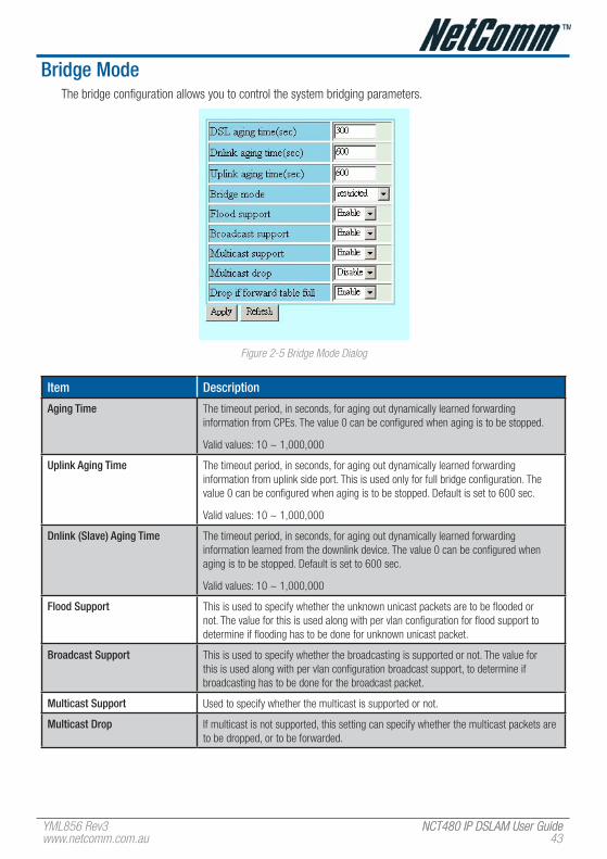
Bridge ModeThe bridge configuration allows you to control the system bridging parameters.
Figure �-5 Bridge Mode Dialog
Item Description
Aging Time The timeout period, in seconds, for aging out dynamically learned forwarding information from CPEs. The value 0 can be configured when aging is to be stopped.
Valid values: 10 ~ 1,000,000
Uplink Aging Time The timeout period, in seconds, for aging out dynamically learned forwarding information from uplink side port. This is used only for full bridge configuration. The value 0 can be configured when aging is to be stopped. Default is set to 600 sec.
Valid values: 10 ~ 1,000,000
Dnlink (Slave) Aging Time The timeout period, in seconds, for aging out dynamically learned forwarding information learned from the downlink device. The value 0 can be configured when aging is to be stopped. Default is set to 600 sec.
Valid values: 10 ~ 1,000,000
flood Support This is used to specify whether the unknown unicast packets are to be flooded or not. The value for this is used along with per vlan configuration for flood support to determine if flooding has to be done for unknown unicast packet.
Broadcast Support This is used to specify whether the broadcasting is supported or not. The value for this is used along with per vlan configuration broadcast support, to determine if broadcasting has to be done for the broadcast packet.
Multicast Support Used to specify whether the multicast is supported or not.
Multicast Drop If multicast is not supported, this setting can specify whether the multicast packets are to be dropped, or to be forwarded.

NCT480 IP DSLAM User Guide YML856 Rev344 www.netcomm.com.au
Item Description
Drop if forwarding Table full This specifies if the frame for which learning could not be done because of forwarding table limit being reached, is to be dropped. If this is enabled, the frame for which learning could not be done because of limit exceeded shall be dropped, else forwarded based on bridge forwarding logic. This being enabled shall reduce flooding, as when a response to such a frame from which learning could not be done shall come the frame shall be flooded, as the entry for that unicast address, shall not be found in forwarding table.
Status of full Bridging Status This specifies the current state of full bridging on the bridge. The bridge can be set to residential bridging, restricted full bridging or unrestricted full bridging.
* Residential bridging, all packets from a CPE side port are sent to Net side port (Uplink ports) without doing a lookup in the forwarding table.
* Restricted bridging, there is a lookup and a packet coming from a CPE port destined for another CPE port is dropped. Hence, CPE-CPE switching is not permitted.
* Unrestricted bridging, all traffic is forwarded based on lookup.
Table �-4 Bridge Configuration Dialog Description
YML856 Rev3 NCT480 IP DSLAM User GuideNCT480 IP DSLAM User Guidewww.netcomm.com.au 45
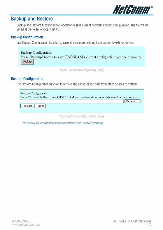
Backup and RestoreBackup and Restore function allows operator to save current network element configuration. The file will be saved at the folder of local host PC.
Backup ConfigurationUse Backup Configuration function to save all configured setting from system to exterior device.
Figure �-6 Backup Configuration Dialog
Restore ConfigurationUse Restore Configuration function to retrieve the configuration data from other devices to system.
Figure �-� Configuration Restore Dialog
The NCT480 web management Backup and Restore file name must be “ipdslam.cfg”.

NCT480 IP DSLAM User Guide YML856 Rev346 www.netcomm.com.au
firmware UpgradeThe upload process uses HTTP (Hypertext Transfer Protocol) and may take up to three minutes.
After a successful upload, the system must reboot.
Figure �-8 Firmware Upgrade Dialog
The following table describes the labels in this screen.
The NCT480 web management Firmware Upgrade file name must be “TEImage.bin.gz”.
Table �-5 Firmware Upgrade Description
Item Description
Browse… Type in the location of the file you want to upload in this field or click Browse… to find the “.bin.gz” file.
Upgrade Click this to begin the upgrade process. This process may take up to three minutes.
Clear Click this to clear the location of the file in this field.
YML856 Rev3 NCT480 IP DSLAM User GuideNCT480 IP DSLAM User Guidewww.netcomm.com.au 4�
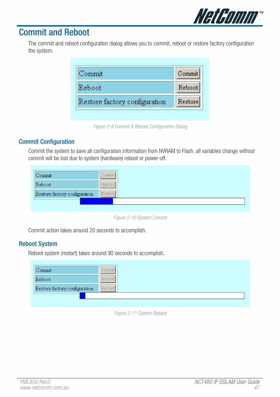
Commit and RebootThe commit and reboot configuration dialog allows you to commit, reboot or restore factory configuration the system.
Figure �-� Commit & Reboot Configuration Dialog
Commit ConfigurationCommit the system to save all configuration information from NVRAM to Flash, all variables change without commit will be lost due to system (hardware) reboot or power-off.
Figure �-10 System Commit
Commit action takes around 20 seconds to accomplish.
Reboot SystemReboot system (restart) takes around 90 seconds to accomplish.
Figure �-11 System Reboot

NCT480 IP DSLAM User Guide YML856 Rev348 www.netcomm.com.au
Restore factory ConfigurationUse restore factory configuration to restore configuration parameters of factory default values.
Figure �-1� Restore Factory Configuration
The restore factory default parameters are list in Table 2-6.
Item Description
ADSL Layer
vPCI (vPI/vCI) 8/35 for each ADSL port interface.
encapsulation LLCMUX
Standard ADSL2+ Auto
Bridge Layer and ethernet IP
Bridge mode Restricted bridge mode
ethernet port 1 IP address 0.0.0.0 / 0.0.0.0, Uplink
ethernet port 2 IP address 0.0.0.0 / 0.0.0.0, Downlink
ethernet port 3 IP address 192.168.1.1 / 255.255.255.0, management port
Management
SNMP community public (re-write privilege)
Web Management Username / Password
admin / admin
CLI Username / Password admin / admin
Telnet Username / Password admin / admin
Table �-6 NCT480 System Factory Default Parameters

YML856 Rev3 NCT480 IP DSLAM User GuideNCT480 IP DSLAM User Guidewww.netcomm.com.au 4�
ChAPTeR 3 STATUS AND PeRfORMANCeIn the Status and Performance menu, operator can view the ADSL line performance parameters and Ethernet statistics as well as the ADSL channel performance parameters and Ethernet statistics.
This chapter contains the following sections:
• DSL Status
• Layer Information
• Ethernet Statistics
• PVC Statistics
• Line 15min Performance
• Line 1day Performance

NCT480 IP DSLAM User Guide YML856 Rev350 www.netcomm.com.au
DSL StatusThe line status shows the ADSL line information.
Figure 3-1 DSL Status Dialog
Item Description
Port selection menu Select the ADSL port interface to be display with relative parameters.
Operation state Operational state of the DSL port.
Current status Indicates current state of the DSL line. This is a bit-map of possible conditions.
Operation mode Operation mode used by the DSL port.
Actual standard Actual standard used for connection, based on the outcome of the negotiation with the ATU-R
Attain rate (bps) Indicates the maximum currently attainable data rate by the ATU-x. This value will be equal to, or greater than the current line rate.
Attenuation (1/10 db) Measured difference in the total power transmitted by the peer ATU-x and the total power received by this ATU-x.
Current SNR (1/10 db) Noise Margin as seen by this ATU-x with respect to its received signal in tenth dB.
Output power (1/10 dbm) Measured total output power transmitted by this ATU-x. This is the measurement that was reported during the last activation sequence.
Rate (bps) Actual transmit rate on this channel.
Interleave delay (ms) Interleave delay for this channel.
Block length (byte) Indicates the length of the channel data-block, on which the CRC operates.
Table 3-1 DSL Status Dialog Description
YML856 Rev3 NCT480 IP DSLAM User GuideNCT480 IP DSLAM User Guidewww.netcomm.com.au 51
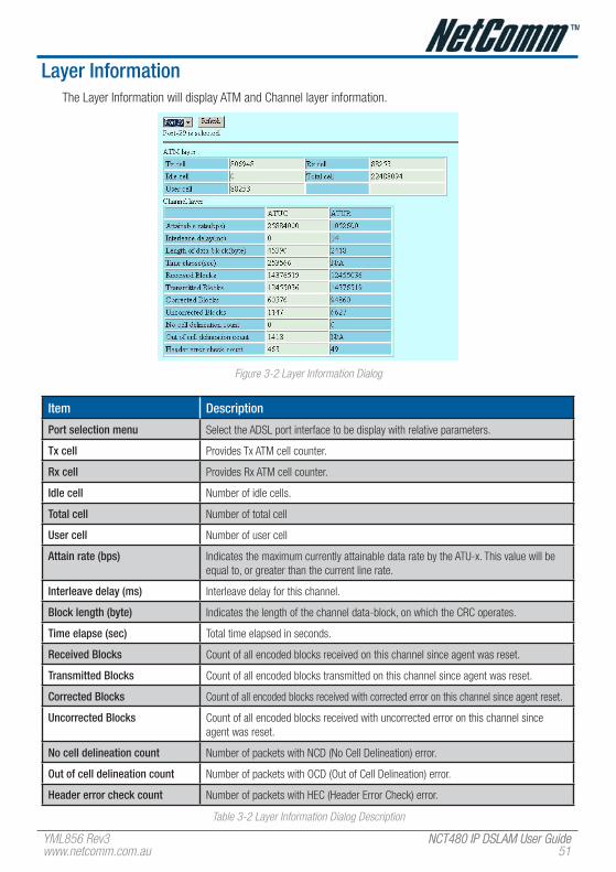
Layer InformationThe Layer Information will display ATM and Channel layer information.
Figure 3-� Layer Information Dialog
Item Description
Port selection menu Select the ADSL port interface to be display with relative parameters.
Tx cell Provides Tx ATM cell counter.
Rx cell Provides Rx ATM cell counter.
Idle cell Number of idle cells.
Total cell Number of total cell
User cell Number of user cell
Attain rate (bps) Indicates the maximum currently attainable data rate by the ATU-x. This value will be equal to, or greater than the current line rate.
Interleave delay (ms) Interleave delay for this channel.
Block length (byte) Indicates the length of the channel data-block, on which the CRC operates.
Time elapse (sec) Total time elapsed in seconds.
Received Blocks Count of all encoded blocks received on this channel since agent was reset.
Transmitted Blocks Count of all encoded blocks transmitted on this channel since agent was reset.
Corrected Blocks Count of all encoded blocks received with corrected error on this channel since agent reset.
Uncorrected Blocks Count of all encoded blocks received with uncorrected error on this channel since agent was reset.
No cell delineation count Number of packets with NCD (No Cell Delineation) error.
Out of cell delineation count Number of packets with OCD (Out of Cell Delineation) error.
header error check count Number of packets with HEC (Header Error Check) error.
Table 3-� Layer Information Dialog Description

NCT480 IP DSLAM User Guide YML856 Rev35� www.netcomm.com.au
ethernet StatisticsThe Ethernet interface statistics allows you to check the packets information of selected Ethernet port.
Figure 3-3 Ethernet Statistics Dialog
Item Description
ethernet port selection menu Select the Ethernet interface to display relative parameters.
Physical address The MAC address used by this Ethernet interface, when it must be referred to, in a unique fashion.
Unknown Protocol Packets The number of packets received by the interface, which were discarded because of an unknown or unsupported protocol.
In Octets The total number of octets received on the interface, including the framing characters. For Ethernet interface, this will have the lower 32 bits of HC in octets.
Out Octets The total number of octets transmitted out the interface, including the framing characters. For Ethernet interface, this will have the lower 32 bits of HC out octets.
In Discards The number of inbound packets, which were discarded, though no errors were detected.
Out Discards The number of outbound packets chosen to be discarded even though there were no errors.
In errors The number of inbound packets, which were not delivered to upper layers because of errors.
Out errors The number of outbound packets to be discarded because there were errors.
In Unicast Packets The number of unicast packets delivered to a higher layer protocol.
Out Unicast Packets The number of packets requested to be sent to unicast addresses, by upper layer protocol.
In Multicast Packets The number of multicast packets delivered to a higher layer protocol.
Out Multicast Packets The number of packets requested to be sent to multicast addresses, by upper layer protocol.
In Broadcast Packets The number of broadcast packets delivered to a higher layer protocol.
Out Broadcast Packets The number of packets requested to be sent to broadcast addresses, by upper layer protocol.
Table 3-3 Ethernet Statistics Dialog Description

YML856 Rev3 NCT480 IP DSLAM User GuideNCT480 IP DSLAM User Guidewww.netcomm.com.au 53
PvC StatisticsPVC statistics will display input output frame information for vpi/vci of each port.
Figure 3-4 PVC Statistics Dialog
Line 15min PerformanceThe ATU line 15min performance data represents line performance related data for a particular channel associated with a particular ATU-C/ATU-R.
Table 3-4 describes line performance field items.
Figure 3-5 ADSL Line 15min Performance Dialog

NCT480 IP DSLAM User Guide YML856 Rev354 www.netcomm.com.au
Line 1day PerformanceThe ATU line 1day performance data represents line performance related data for a particular channel associated with a particular ATU-C/ATU-R. Table 3-4 describes the line performance field items.
Figure 3-6 ADSL Line 1day Performance Dialog
Item DescriptionPort selection menu Select the ADSL port interface to display relative parameters.
LOfS Loss of Frame Second. This specifies the second which no corrected frame is received.
LOSS Loss of Signal Second. This specifies the second which no signal is received.
LOLS Loss of Link Second. This specifies the second which the link appears to be failed.
LPRS Loss of Power Resource Second. This specifies the second which the power is cut off.
eS Error Second. This specifies the second which error occurs and can not be recovered from CRC bit.
INITS Initialization Second. This specifies the second which initialization has occurred.
SeS Severely Error Second. This specifies the second which LOS, LOF, LOL have occurred.
UAS Unavailable Second. This specifies the second which the link is abnormal for 10 seconds.
Table 3-4 Line Performance Dialog Description
Alarm I/O StatusIn the alarm I/O status dialog, you can monitor the temperature and Fan status of NCT480 IP-DSLAM.
Figure 3-� Alarm I/O Status Dialog
Item Descriptionfan This specifies the Fan alarm status.
Temperature This specifies the Temperature alarm status.
Local temperature (oC) This specifies the local temperature.
Remote temperature (oC) This specifies the remote temperature.
Table 3-5 Alarm I/O Dialog Description
YML856 Rev3 NCT480 IP DSLAM User GuideNCT480 IP DSLAM User Guidewww.netcomm.com.au 55
ChAPTeR 4 DePLOyMeNT MeNUThe deployment menu contains DSL profile, physical interface setting, network Ethernet and ADSL port.
This chapter contains the following sections:
• DSL Port
• DSL Profile Configuration
• DSL Profile Mapping
• DSL Alarm Profile
• Power Management Mode
• PVC Setting
• Route Setting
• Ethernet Setting
• SNMP Host
• SNMP Community
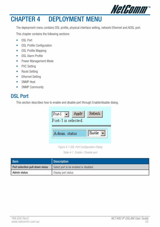
DSL PortThis section describes how to enable and disable port through Enable/disable dialog.
Figure 4-1 DSL Port Configuration Dialog
Table 4-1 Enable / Disable port
Item Description
Port selection pull down menu Select port to be enabled or disabled
Admin status Display port status

NCT480 IP DSLAM User Guide YML856 Rev356 www.netcomm.com.au
DSL Profile ConfigurationThis section describes the static Line (ADSL) profile configuration. Line Profile Configuration dialog allows you to modify the ADSL connection parameters of each DSL profile.
Figure 4-� DSL Profile Configuration

YML856 Rev3 NCT480 IP DSLAM User GuideNCT480 IP DSLAM User Guidewww.netcomm.com.au 5�
Add DSL ProfileAdd DSL profile dialog allows you to create the ADSL connection parameters. Enter the control values to the text box and click ‘Add’ to activate.
Figure 4-3 Add DSL Profile Dialog
Item Description
Profile name Select a DSL profile to display relative parameters.
Line Interface
Standard type Preferred standard compliance. Outcome is dependent upon standard support of the remote unit.
AnnexM This extends the capability of basic ADSL2 by doubling the number of upstream bits.
Line Type This specifies the type of channel on which the ATM VC’s cells have to be transmitted and received.
Possible choice: Interleave Only/Fast Only
* Interleave mode is used when transmission error correction is necessary due to a less than ideal telephone line.
* Fast mode will result in faster transmission rate.
Rate Mode This specifies what form of transmission rate adaptation is configured on this port.
fixed – Connect over the fixed speed given by ‘Tx Rate’ field, the connection gets fail if it can not reach the lengths and qualities of lines
adaptAtStartup – Connect over the range of speed given by ‘Tx Rate’ field, the connection gets retrain due to varying qualities of lines.
adaptAtRuntime – Connect over the range of speed given by ‘Tx Rate’ field, the connection is auto rearrange seamlessly due to varying qualities of lines.
SNR Margin (ATUC/ATUR)
Target SNR Margin This specifies Target SNR Margin which the ATU-R must achieve with a BER of 10 to the power -7 or better, to successfully complete initialization.
Valid values: 0 ~ 310 (dB/10)
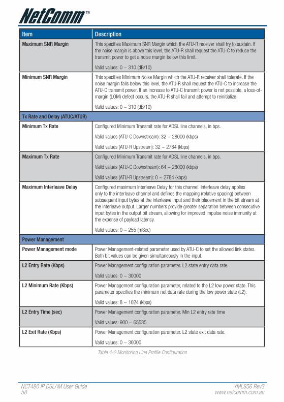
NCT480 IP DSLAM User Guide YML856 Rev358 www.netcomm.com.au
Item Description
Maximum SNR Margin This specifies Maximum SNR Margin which the ATU-R receiver shall try to sustain. If the noise margin is above this level, the ATU-R shall request the ATU-C to reduce the transmit power to get a noise margin below this limit.
Valid values: 0 ~ 310 (dB/10)
Minimum SNR Margin This specifies Minimum Noise Margin which the ATU-R receiver shall tolerate. If the noise margin falls below this level, the ATU-R shall request the ATU-C to increase the ATU-C transmit power. If an increase to ATU-C transmit power is not possible, a loss-of-margin (LOM) defect occurs, the ATU-R shall fail and attempt to reinitialize.
Valid values: 0 ~ 310 (dB/10)
Tx Rate and Delay (ATUC/ATUR)
Minimum Tx Rate Configured Minimum Transmit rate for ADSL line channels, in bps.
Valid values (ATU-C Downstream): 32 ~ 28000 (kbps)
Valid values (ATU-R Upstream): 32 ~ 2784 (kbps)
Maximum Tx Rate Configured Minimum Transmit rate for ADSL line channels, in bps.
Valid values (ATU-C Downstream): 64 ~ 28000 (kbps)
Valid values (ATU-R Upstream): 0 ~ 2784 (kbps)
Maximum Interleave Delay Configured maximum Interleave Delay for this channel. Interleave delay applies only to the interleave channel and defines the mapping (relative spacing) between subsequent input bytes at the interleave input and their placement in the bit stream at the interleave output. Larger numbers provide greater separation between consecutive input bytes in the output bit stream, allowing for improved impulse noise immunity at the expense of payload latency.
Valid values: 0 ~ 255 (mSec)
Power Management
Power Management mode Power Management-related parameter used by ATU-C to set the allowed link states. Both bit values can be given simultaneously in the input.
L2 entry Rate (Kbps) Power Management configuration parameter. L2 state entry data rate.
Valid values: 0 ~ 30000
L2 Minimum Rate (Kbps) Power Management configuration parameter, related to the L2 low power state. This parameter specifies the minimum net data rate during the low power state (L2).
Valid values: 8 ~ 1024 (kbps)
L2 entry Time (sec) Power Management configuration parameter. Min L2 entry rate time
Valid values: 900 ~ 65535
L2 exit Rate (Kbps) Power Management configuration parameter. L2 state exit data rate.
Valid values: 0 ~ 30000
Table 4-� Monitoring Line Profile Configuration

YML856 Rev3 NCT480 IP DSLAM User GuideNCT480 IP DSLAM User Guidewww.netcomm.com.au 5�
DSL Profile MappingThis section helps you to attach the DSL profile to the ADSL line interface.
Figure 4-4 DSL Profile Mapping Dialog
Table 4-4 shows the default parameter values if the DSL profile is ‘NONE’.
Item Description
from This specifies the starting ADSL port interface for ATM PVC configuration.
To This specifies the ending ADSL port interface for ATM PVC configuration.
Profile Name This specifies the profile name. (DSL Profile)
Table 4-3 DSL Profile Mapping
Item Setting
Line Interface
Standard type ADSL2Plus
AnnexM off
Line Type interleave
Rate Mode adaptAtStartup
SNR Margin (ATUC/ATUR)
Target SNR Margin (db/10) 60
Minimum SNR Margin (db/10) 0
Maximum SNR Margin (db/10) 310
Tx Rate and Delay (ATUC/ATUR)
Minimum Tx Rate (Kbps) 64
Maximum Tx Rate (Kbps) ATUC: 28000
ATUR: 1088

NCT480 IP DSLAM User Guide YML856 Rev360 www.netcomm.com.au
Item Setting
Maximum Interleave Delay (ms) 16
Power Management
Power Management mode L2 & L3 enable
L2 entry Rate (Kbps) 256
L2 Minimum Rate (Kbps) 1024
L2 entry Time (sec) 1800
L2 exit Rate (Kbps) 512
Table 4-4 Default DSL Profile Setting
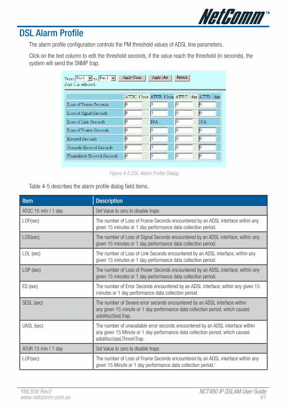
YML856 Rev3 NCT480 IP DSLAM User GuideNCT480 IP DSLAM User Guidewww.netcomm.com.au 61
DSL Alarm ProfileThe alarm profile configuration controls the PM threshold values of ADSL line parameters.
Click on the text column to edit the threshold seconds, if the value reach the threshold (in seconds), the system will send the SNMP trap.
Figure 4-5 DSL Alarm Profile Dialog
Table 4-5 describes the alarm profile dialog field items.
Item Description
ATUC 15 min / 1 day Set Value to zero to disable traps
LOF(sec) The number of Loss of Frame Seconds encountered by an ADSL interface within any given 15 minutes or 1 day performance data collection period.
LOS(sec) The number of Loss of Signal Seconds encountered by an ADSL interface, within any given 15 minutes or 1 day performance data collection period.
LOL (sec) The number of Loss of Link Seconds encountered by an ADSL interface, within any given 15 minutes or 1 day performance data collection period.
LOP (sec) The number of Loss of Power Seconds encountered by an ADSL interface, within any given 15 minutes or 1 day performance data collection period.
ES (sec) The number of Error Seconds encountered by an ADSL interface, within any given 15 minutes or 1 day performance data collection period.
SESL (sec) The number of Severe error seconds encountered by an ADSL interface within any given 15 minute or 1 day performance data collection period, which causes adslAtucSesLTrap.
UASL (sec) The number of unavailable error seconds encountered by an ADSL interface within any given 15 Minute or 1 day performance data collection period, which causes adslAtucUasLThreshTrap.
ATUR 15 min / 1 day Set Value to zero to disable traps
LOF(sec) The number of Loss of Frame Seconds encountered by an ADSL interface within any given 15 Minute or 1 day performance data collection period.’

NCT480 IP DSLAM User Guide YML856 Rev36� www.netcomm.com.au
Item Description
LOS(sec) The number of Loss of Signal Seconds encountered by an ADSL interface, within any given 15 Minute or 1 day performance data collection period.
LOP (sec) The number of Loss of Power Seconds encountered by an ADSL interface, within any given 15 Minute or 1 day performance data collection period.
ES (sec) The number of Error Seconds encountered by an ADSL interface, within any given 15 Minute or 1 day performance data collection period.
SESL (sec) The number of Severe Error Seconds encountered by an ADSL interface within any given 15 Minute or 1 Day performance data collection period, which causes adslAtucSesLTrap.
UASL (sec) The number of unavailable error seconds encountered by an ADSL interface within any given 15 Minute or 1 Day performance data collection period, which causes adslAtucUasLThreshTrap.
Table 4-5 DSL Alarm Profile Dialog Description

YML856 Rev3 NCT480 IP DSLAM User GuideNCT480 IP DSLAM User Guidewww.netcomm.com.au 63
Power Management ModeThe power management allows you to furnish the efficiency of ADSL power output.
First-generation ADSL transceivers operate in full-power mode (L0) day and night, even when not in use. To address these concerns, the ADSL2 standard brings in two power management modes that help to reduce overall power consumption while maintaining ADSL’s “always-on” functionality for the user. These modes are the L2 and L3 power modes.
The L2 low-power mode enables statistical powers savings at the ADSL transceiver unit in the central office (ATU-C) by rapidly entering and exiting low power mode based on Internet traffic running over the ADSL connection. When large files are being downloaded, ADSL2 operates in full power mode (called “L0” power mode) in order to maximize the download speed. When Internet traffic decreases, such as when a user is reading a long text page, ADSL2 systems can transition into L2 low power mode, in which the data rate is significantly decreased and overall power consumption is reduced. While in L2, the ADSL2 system can instantly re-enter L0 and increase to the maximum data rate as soon the user initiates a file download. The L2 entry/exit mechanisms and resulting data rate adaptations are accomplished without any service interruption or even a single bit error, and as such, are not noticed by the user.
The L3 power modem on the other hand, enables overall power savings at both the ATU-C and the remote ADSL transceiver unit (ATU-R) by entering into sleep mode when the connection is not being used for extended periods of time. L3 is a sleep mode where traffic cannot be communicated over the ADSL connection when the user is not online. When the user returns to go on-line the ADSL transceivers require at least 2 to 3 seconds to re-initialize and to enter into steady-state communication mode.
Figure 4-6 Power Management Forced State
NCT480 IP DSLAM User Guide YML856 Rev364 www.netcomm.com.au
PvC SettingThe PVC Management dialog has the ability to configure the ATM PVC on ADSL port interface.
ATM (Asynchronous Transfer Mode) is more efficient than synchronous technologies like time-division multiplexing (TDM). With TDM, each station or users is pre-assigned some time slots, and no other station can send in that time slot. With ATM being asynchronous in nature, time slots are available on demand.
ATM supports integrated voice, data, and video communications. In ATM the information to be transmitted in divided into short 53 byte packets or cells, which have a 5 byte header. The reason for such a short cell length is that ATM must deliver real time service at low bit rates and thus it minimizes packetization delay. ATM networks are connection oriented with virtual channels and virtual paths. The virtual channel carries one connection while a virtual path may carry a group of virtual channels. This ensures that cell sequence is maintained throughout the network. The virtual channel is identified by the Virtual Channel Identifier, (VCI), and the virtual path is identified by the Virtual Path Identifier, (VPI). Both the VCI and VPI may change within the network and they are stored in the header of the cell.
AAL (ATM Adaptation Layer) makes the ATM layer services more adaptable to specific services. The specific services may include user services, control services and management services. The AAL is the layer above the ATM layer and it is responsible for converting the information from the higher layers into 48 byte lengths so that the ATM layer can add the 5 byte header to make the 53 byte cell. The two main functions of this AAL are to provide functions needed to support applications and to break up information into units that will fit into cells. There are five AAL layers and each layers is loosely associated with the class of traffic to be carried. AAL1 is designed to support constant bit rate, connection oriented, and synchronous traffic such as uncompressed video transmission. AAL2 is never completed, but it was envisioned to be assigned for variable bit rate, connection-oriented, synchronous traffic. AAL3/4 supports variable bit rate, connection oriented, and asynchronous traffic or connectionless packet data. AAL5 is the primary AAL for data and supports both connection oriented and connectionless data.

YML856 Rev3 NCT480 IP DSLAM User GuideNCT480 IP DSLAM User Guidewww.netcomm.com.au 65
Figure 4-� PVC Setting Dialog
Table 4-6 describes the column status of PVC setting.
Column Item Description
Port This indicates the physical DSL port interface.
vPI The virtual path identifier of correspond DSL port interface.
vCI The virtual circuit identifier of correspond DSL port interface.
encapsulation type This specifies the data multiplexing method to be used over the AAL5 layer. Adjacent CPE must use the same encapsulation to establish the connection.
Possible choice: LLCMux* or VCMux*.
* LLC encapsulation enables one Virtual Channel to carry multiple protocols with each packet header containing protocol identifying information. VC encapsulation engages each protocol with a specific virtual channel.
Table 4-6 Monitoring the PVC Management

NCT480 IP DSLAM User Guide YML856 Rev366 www.netcomm.com.au
Add Port & PvCClick ‘Add’ button to create a new PVC of single or range of ADSL port interface.
A total of eight PVCs can be allowed under a single DSL port.
Figure 4-8 Add Port & PVC Dialog
Table 4-7 describes the Add PVC dialog.
Item Description
Port selection pull down menu This specifies the ADSL port interface for ATM PVC configuration.
vPI This specifies the virtual path identifier for use at DSL port interface.
Valid values: 0 ~ 255
vCI This specifies the virtual circuit identifier for use at DSL port interface.
Valid values: 1 ~ 65535 (1 ~ 31 are reserved)
Type Be sure to use the encapsulation method required by the ATU-R. The NCT480 IP-DSLAM supports the following methods.
EOA: Ethernet over ATM. EoA benefits from SONET/SDH protection but has been criticized for being expensive and having scalability issues. EoA offers smooth roll out of Ethernet-based services in existing Asynchronous Transfer Mode ATM network and optimizes the use of spare capacity in the ATM network.
IPOA: Some CPE devices have IPoA interfaces towards the WAN side. These interfaces need to be supported and retained by the service providers. Also DSLAMs are moving from ATM to Packet mode and hence support for these interfaces on the CPE side becomes essential. In order to provide this flexibility in the route mode firmware release R2.0, RFC 2684 Routed (IPoA) interfaces along with the existing RFC 2684 Bridged Ethernet interfaces shall be supported.
PPPOA: PPPoA stands for Point to Point Protocol over ATM Adaptation Layer5 (AAL5). A PPPoA connection functions like a dial-up Internet connection. The NCT480 IP-DSLAM encapsulates the PPP session based on RFC1483 and sends it through an ATM PVC (Permanent Virtual Circuit) to the CPEs. Please refer to RFC2364 for more information on PPPoA. Refer to RFC1661 for more information on PPP.
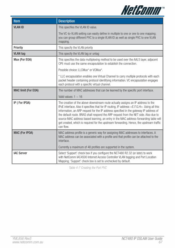
YML856 Rev3 NCT480 IP DSLAM User GuideNCT480 IP DSLAM User Guidewww.netcomm.com.au 6�
Item Description
vLAN ID This specifies the VLAN ID value.
The VC-to-VLAN setting can easily define in multiple to one or one to one mapping; you can group different PVC to a single VLAN ID as well as single PVC to one VLAN mapping.
Priority This specify the VLAN priority
vLAN tag This specify the VLAN tag or untag
Mux (for eOA) This specifies the data multiplexing method to be used over the AAL5 layer, adjacent CPE must use the same encapsulation to establish the connection.
Possible choice: LLCMux* or VCMux*.
* LLC encapsulation enables one Virtual Channel to carry multiple protocols with each packet header containing protocol identifying information. VC encapsulation engages each protocol with a specific virtual channel.
MAC limit (for eOA) The number of MAC addresses that can be learned by the specific port interface.
Valid values: 1 ~ 16
IP ( for IPOA) The creation of the above downstream route actually assigns an IP address to the IPoE interface. Also it specifies that for IP routing, IP address <E.F.G.H>. Using all this information, an ARP request for the IP address specified in the gateway IP address of the default route. BRAS shall respond the ARP request from the NET side. Also due to source MAC address based learning, an entry in the MAC address-forwarding table will get created, which is required for the upstream forwarding. Hence, the upstream traffic can flow.
MAC (for IPOA) MAC address profile is a generic way for assigning MAC addresses to interfaces. A MAC address can be associated with a profile and that profile can be attached to the interface.
Currently a maximum of 48 profiles are supported in the system.
IAC Server Select ‘Support’ check box if you configure the NCT480 R2.32 (or later) to work with NetComm IAC4500 Internet Access Controller VLAN tagging and Port Location Mapping; ‘Support’ check box is set to unchecked by default.
Table 4-� Creating the Port PVC

NCT480 IP DSLAM User Guide YML856 Rev368 www.netcomm.com.au
Set PPPoA MACThe PPPoA MAC address to be used in the PPPoE packets from DSLAM to the BRAS is configurable. One MAC address can be assigned to multiple PPPoA terminations. The PPPoE session identifier is additionally used to perform the de-multiplexing in the BRAS to customer direction.
Figure 4-� Set PPPoA MAC Dialog
Item Description
PPPoA MAC Configure the MAC address to be used by the PPPoE tunnel interface.
Table 4-8 Add PPPoA MAC

YML856 Rev3 NCT480 IP DSLAM User GuideNCT480 IP DSLAM User Guidewww.netcomm.com.au 6�
Route SettingA static route defines how the DSLAM should forward traffic by configuring the TCP/IP parameters manually.
Figure 4-10 Display the Routing Table
Click ‘Add’ button to create the routing table.
Figure 4-11 Route Setting Dialog

NCT480 IP DSLAM User Guide YML856 Rev3�0 www.netcomm.com.au
ethernet SettingThe Ethernet Interface allows you to manage the network Ethernet port.
NCT480 IP DSLAM has two GE interface for uplink/downlink purposes. The IP address associates with the uplink and downlink interface are only for system management purpose. The IP address assigned to the Ethernet ports must be in different subnets.
Figure 4-1� Ethernet Port Configuration Dialog
Select an Ethernet Port to show the parameters, edit the control value in text box and click ‘Apply’ to modify or click ‘Add’ to create a new Ethernet port.
Item Description
ethernet Port pull down menu Select the Ethernet port from pull down menu.
IP Address This specifies the network IP address of given Ethernet interface. This IP address is for system management use only.
Valid values: Any valid class A/B/C address
Net Mask This specifies the network mask configured for the interface.
Valid values: 255.0.0.0 ~ 255.255.255.255
Is use DhCP This indicates whether a DHCP client is to be triggered to obtain an IP address for this Ethernet interface.
Interface Type The type of Ethernet interface, net or slave.
Actual Duplex Mode The duplex mode use by the Ethernet interface.
Output Rate Limit This parameter specifies the output rate limiting value to be applied on this interface. The unit is in Mbits/sec. This setting will have effect on receiving data rate of specified port.
Valid values: 0 ~ 300 Mbps
Management vLAN ID VLAN for management traffic on this interface. Nonzero value of this field is valid only if either ‘IP Address’ field is non-zero or ‘does use DHCP’ field is true. If no Management VLAN ID is specified (in the create operation) or its value is set to zero (either in create or modify operation) then the system shall use the value of ‘private VLAN ID’ associated with the bridge port created on this interface as the Management VLAN ID.
In case the management VLAN (i.e. ‘Management VLAN ID’ or the associated ‘private VLAN ID’, if ‘Management VLAN ID’ is zero) does not exist on the system then IP based management on this management VLAN shall not happen on the interface till the corresponding VLAN is created with the Network side port as its member.
Default values: 0
Valid values: 0 ~ 4094

YML856 Rev3 NCT480 IP DSLAM User GuideNCT480 IP DSLAM User Guidewww.netcomm.com.au �1
Item Description
Tagged PDU Management Priority
Priority to be set in Tagged Ethernet PDUs sent on Management VLAN over this interface. This field is valid only if either ‘IP Address’ field is non-zero or ‘does use DHCP’ field is true.
Valid values: 0 ~ 7
Port Speed This specifies the port speed for the Network Ethernet interfaces. The ‘auto select’ specifies that the interface will determine the line speed using auto-negotiation.
Table 4-� Monitoring the Ethernet Port

NCT480 IP DSLAM User Guide YML856 Rev3�� www.netcomm.com.au
Add ethernet InterfaceNCT480 IP-DSLAM supports two Ethernet interfaces and one management port (Ethernet port-3). The IP address is only for management purpose and each Ethernet interface can be applied with its IP address.
Figure 4-13 Add Ethernet Interface Dialog
Network type ‘downlink’ is for system stacking. Ethernet ports that are not used for DSLAM system management purpose do not need to be assigned with an IP address.
Beware when select on the ‘Non IP’ option and ‘Delete’ button, the management connection to that particular Ethernet port may be loss due to those setting.
Item Description
Select an ethernet port to add Select the Ethernet port from pull down menu.
Network Type This specifies the type of the Ethernet interfaces. The uplink is towards the Network side (2 at most) and downlink is towards the physical interface connected to the slave device. For uplink type, IP address can not be null, if ‘Is use DHCP’ is false.
Use DhCP The Ethernet interface will request an IP Address to be assigned by a DHCP Server in the network.
Non-IP Select Non IP to restrict the IP management activity.
IP address & netmask
IP Address This specifies the network IP address of given Ethernet interface, this IP address use for only system management.
Valid values: Any valid class A/B/C address
Net Mask This specifies the network mask configured for the interface.
Valid values: 255.0.0.0 ~ 255.255.255.255
Table 4-10 Creating the Ethernet Port

YML856 Rev3 NCT480 IP DSLAM User GuideNCT480 IP DSLAM User Guidewww.netcomm.com.au �3
SNMP hostThe SNMP Host configuration dialog allows you to manage the Host IP and corresponded SNMP community.
Figure 4-14 SNMP Host Configuration Dialog
Click ‘Add’ button to create a new SNMP Host IP address.
The Host IP is the device (PC) IP address allowed to manage the IP-DSLAM via AMS (Advanced Management Service). It is recommended to limit the number of host device.
Figure 4-15 Add Host IP Address Dialog
Table 4-11 describes fields in the Add Host IP Address Dialog.
Item Description
IP Address This specifies the IP address of the manager that has access permissions.
Valid values: Any valid class A/B/C address
Community This indicates the community name specify on community configuration.
Access This indicates the access permissions given to managers with this community name.
Table 4-11 Configure Host IP
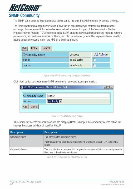
NCT480 IP DSLAM User Guide YML856 Rev3�4 www.netcomm.com.au
SNMP CommunityThe SNMP community configuration dialog allows you to manage the SNMP community access privilege.
The Simple Network Management Protocol (SNMP) is an application layer protocol that facilitates the exchange of management information between network devices. It is part of the Transmission Control Protocol/Internet Protocol (TCP/IP) protocol suite. SNMP enables network administrators to manage network performance, find and solve network problems, and plan for network growth. The Trap operation is used by agents to asynchronously inform the NMS of a significant event.
Figure 4-16 SNMP Community Configuration Dialog
Click ‘Add’ button to create a new SNMP community name and access permission.
Figure 4-1� Add Community Dialog
The community access has relationship to the mapping Host IP, changed the community access option will change the access privilege of specifics Host IP.
Description Description
Community name This specifies the community name.
Valid values: String of up to 20 characters (All characters except ‘;’, ‘?’, and empty space)
Community Access This specifies the access permissions given to managers with this community name in Read only or Read-write permissions.
Table 4-1� Configuring the SNMP Community

YML856 Rev3 NCT480 IP DSLAM User GuideNCT480 IP DSLAM User Guidewww.netcomm.com.au �5
Alarm I/O ControlThe alarm I/O control allows you to define the alarm input and output. Please see “System Installation Guide” for the definition.
Once the normal status of input signal is different from the current status, the NCT480 will launch an “abnormal status” alarm of the specified output to terminal or administrator.
Figure 4-18 Alarm I/O Control Dialog
Item Description
Index 1~4 This indicates the location of relay input ports (1 ~ 4).
Alarm profile This indicates the alarm profile of the specified relay input that configured by operator.
Input value This indicates the current status of the specified relay input.
Alarm status This indicates the alarm status.
Output value This specifies the status of out alarm configuration.
0: always output 0
1: always output 1
0alarm: usually output 1, output 0 when alarm occur
1alarm: usually output 0, output 1 when alarm occur
Local temperature This specifies the local alarm temperature value.
Remote temperature This specifies the remote alarm temperature value.
Table 4-14 Alarm I/O Control
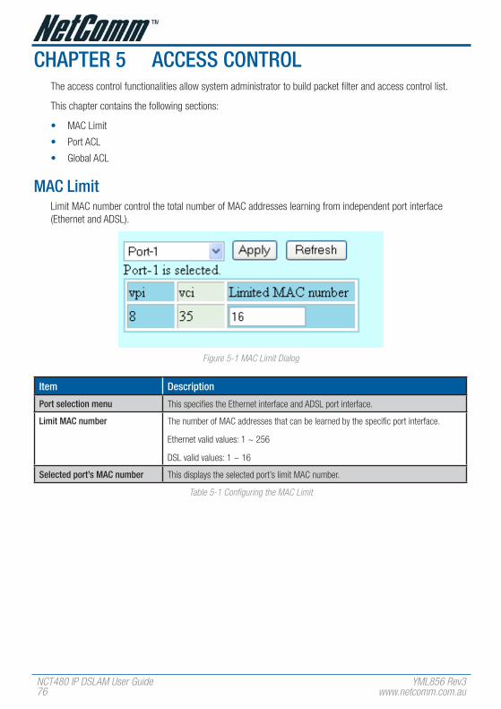
NCT480 IP DSLAM User Guide YML856 Rev3�6 www.netcomm.com.au
ChAPTeR 5 ACCeSS CONTROLThe access control functionalities allow system administrator to build packet filter and access control list.
This chapter contains the following sections:
• MAC Limit
• Port ACL
• Global ACL
MAC LimitLimit MAC number control the total number of MAC addresses learning from independent port interface (Ethernet and ADSL).
Figure 5-1 MAC Limit Dialog
Item Description
Port selection menu This specifies the Ethernet interface and ADSL port interface.
Limit MAC number The number of MAC addresses that can be learned by the specific port interface.
Ethernet valid values: 1 ~ 256
DSL valid values: 1 ~ 16
Selected port’s MAC number This displays the selected port’s limit MAC number.
Table 5-1 Configuring the MAC Limit
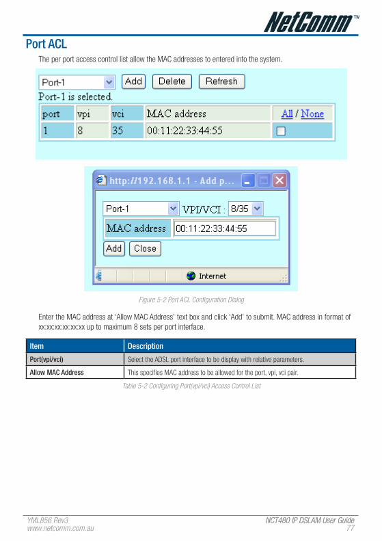
YML856 Rev3 NCT480 IP DSLAM User GuideNCT480 IP DSLAM User Guidewww.netcomm.com.au ��
Port ACLThe per port access control list allow the MAC addresses to entered into the system.
Figure 5-� Port ACL Configuration Dialog
Enter the MAC address at ‘Allow MAC Address’ text box and click ‘Add’ to submit. MAC address in format of xx:xx:xx:xx:xx:xx up to maximum 8 sets per port interface.
Item Description
Port(vpi/vci) Select the ADSL port interface to be display with relative parameters.
Allow MAC Address This specifies MAC address to be allowed for the port, vpi, vci pair.
Table 5-� Configuring Port(vpi/vci) Access Control List

NCT480 IP DSLAM User Guide YML856 Rev3�8 www.netcomm.com.au
Global ACLThe global access control list denies the MAC addresses pass-through the system at all port interface.
Figure 5-3 Global ACL Configuration Dialog
Enter the MAC address at ‘Drop packets come from the MAC Address’ text box and click ‘Add’ to submit. MAC address in format of xx:xx:xx:xx:xx:xx up to maximum 256 sets per system.
Item Description
Deny MAC Address Source MAC address to be dropped
Table 5-3 Configuring Global Access Control List

YML856 Rev3 NCT480 IP DSLAM User GuideNCT480 IP DSLAM User Guidewww.netcomm.com.au ��
ChAPTeR 6 PROTOCOL MeNUProtocol menu contains setting for VLAN, IGMP, DHCP/PPPoE relay configuration and Rapid Spanning Tree Protocol.
This chapter contains the following sections:
• VLAN Port
• Trunk VLAN Setting
• IGMP Snooping
• DHCP & PPPoE Relay
• Spanning Tree Protocol
• Rapid Spanning Tree Protocol
vLAN PortThe VLAN port management allows you to control the accept frame type and ingress filtering status of port interface.
Figure 6-1 VLAN Ports Management Dialog
Item Description
Accept frames Type The set of ports, which are transmitting traffic for this VLAN, as either tagged or untagged frames.
When this is Tagged, the device will discard untagged frames or priority-Tagged frames received on this port. When All, untagged frames or Priority-Tagged frames received on this port will be accepted and assigned to the PVID for this port.
Ingress filtering When this is true, the device will discard incoming frames for VLANs, which do not include this Port in its Member set. When false, the port will accept all incoming frames.
Default vLAN ID The VLAND ID to be assigned if untagged frames are accepted.
Press the ‘Apply’ button to confirm the setting.
Table 6-1 VLAN Ports Management Dialog Description

NCT480 IP DSLAM User Guide YML856 Rev380 www.netcomm.com.au
Trunk vLAN SettingThe trunk VLAN setting dialog list the existing trunk VLAN and its configuration.
A VLAN allows a physical network to be divided into several logical networks. A device can belong to more than one VLAN group. Devices that are not in the same VLAN groups can not talk to each other. VLAN can provide isolation and security to users and increase performance by limiting broadcast domain. VLAN tag can be added to the MAC header to identify the VLAN membership of a frame across bridges. A tagged frame is four bytes longer than an untagged frame. Each port of NCT480 is capable of passing tagged or untagged frames.
Figure 6-� Trunk VLAN Setting Dialog
Click ‘Add’ button to set the new trunk VLAN with associate port interface.

YML856 Rev3 NCT480 IP DSLAM User GuideNCT480 IP DSLAM User Guidewww.netcomm.com.au 81
Add Trunk vLAN
Figure 6-3 Add Trunk VLAN Dialog
Item Description
vLAN ID The VLAN identifier assigned to a specific VLAN. VLAN 1 is the default VLAN Valid values: 0~4095. [0 is reserved for priority tag, 4095 is reserved]
Number of vLAN This indicate the VLAN ID increment number.
Tagged/Untagged This setting determines a specific port to receive tagged or untagged frame.
Table 6-� Configuring VLAN Port Member
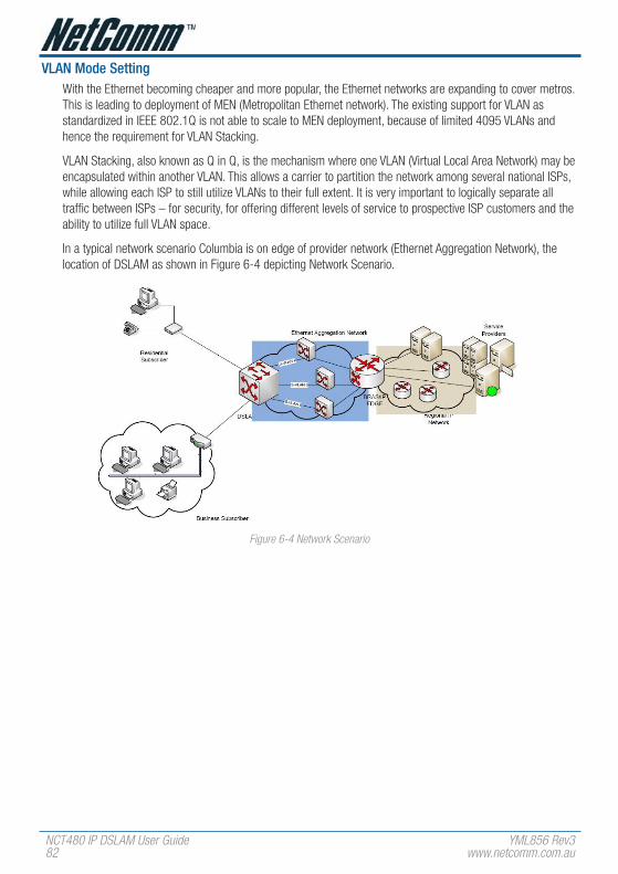
NCT480 IP DSLAM User Guide YML856 Rev38� www.netcomm.com.au
vLAN Mode SettingWith the Ethernet becoming cheaper and more popular, the Ethernet networks are expanding to cover metros. This is leading to deployment of MEN (Metropolitan Ethernet network). The existing support for VLAN as standardized in IEEE 802.1Q is not able to scale to MEN deployment, because of limited 4095 VLANs and hence the requirement for VLAN Stacking.
VLAN Stacking, also known as Q in Q, is the mechanism where one VLAN (Virtual Local Area Network) may be encapsulated within another VLAN. This allows a carrier to partition the network among several national ISPs, while allowing each ISP to still utilize VLANs to their full extent. It is very important to logically separate all traffic between ISPs – for security, for offering different levels of service to prospective ISP customers and the ability to utilize full VLAN space.
In a typical network scenario Columbia is on edge of provider network (Ethernet Aggregation Network), the location of DSLAM as shown in Figure 6-4 depicting Network Scenario.
Figure 6-4 Network Scenario

YML856 Rev3 NCT480 IP DSLAM User GuideNCT480 IP DSLAM User Guidewww.netcomm.com.au 83
With VLAN stacking, if one ISP provisioned an end user into “VLAN 1”, and another ISP provisioned one of their end users into “VLAN 1”, the two end users would not receive each other’s traffic.
Figure 6-5 VLAN Mode Setting Dialog
Item Description
vLAN mode Single VLAN: The single VLAN Mode confirms to the normal 802.1Q VLAN support and the system will continue to work as is in the current model without VLAN stacking.
Double VLAN: VLAN used in VLAN aware networks based on 802.1Q bridging is called C-VLAN (Customer-VLAN), and can be uniquely identified by a C-VLAN tag VLAN that encapsulates Customer traffic in Provider network is called S-VLAN or Service VLAN and is identified by an S-VLAN ID, used as second VLAN tag. In this mode the features can be used to meet custom VLAN stacking requirements.
Press the ‘Apply’ button to confirm the setting.
Table 6-3 VLAN Mode Setting Description

NCT480 IP DSLAM User Guide YML856 Rev384 www.netcomm.com.au
IGMP SnoopingThe IGMP Snooping allows you to view and change the IGMP Snooping administrate status.
IP traffic can be transmitted in one of either three ways: unicast (one sender to one receiver), broadcast (one sender to all members on the network) or multicast (one sender to a group of hosts). IGMP is a session-layer (layer-3) protocol used to establish membership in a multicast group.
Multicast addresses are Class D IP address, from 224.0.0.0 to 239.255.255.255. These addresses are also referred to as Group Destination Address (GDA). Each GDA address is associated with one MAC address. The GDA MAC address is constructed by joining 01:00:5E and the last 23 bits of the GDA multicast IP address in Hex. For example, GDA 224.1.1.1 corresponds to MAC address 01:00:5E:01:01:01
A layer-2 switch supported IGMP snooping can passively snoop on IGMP Query, Report and Leave packets transferred between Routers/Switches and hosts to learn the IP Multicast group membership. It snoops IGMP packets passing through it, picks out the group registration information, and configures multicasting accordingly.
Figure 6-6 IGMP Snooping Dialog
Item Description
DSLAM IGMP Snooping Status Specified whether or not IGMP Snooping is to be enabled in the system.
(ethernet) Port ID This specifies the network port interface.
vPI/vCI This specifies the virtual path, circuit identification for the PVC in the port.
IGMP Snooping Status A Bridge Port, for which IGMP Snooping needs to be enabled or disabled.
Leave Mode IGMP Snooping Leave message processing mode for the port.
If the mode is set to ‘Normal’, the Leave message is forwarded to the Querier and then based on the Query received from Querier the Leave processing is triggered.
If the mode is set to ‘Fast’, the port is immediately deleted from that multicast group on Leave message reception and then the Leave message is forwarded. The mode should be set to ‘Fast’ for a port only if there is one host behind the port. This is because if there are multiple hosts behind the port then it will lead to traffic disruption for other hosts who might still be listening to that multicast group.
If mode is set to ‘FastNormal’, the Leave message is forwarded and the Leave processing is triggered immediately without waiting for any trigger from the Querier. ‘FastNormal’ mode thus saves the delay (equal to the time taken for Leave message to reach router and Querier processing time for it and the time taken for Query to reach IGMP Snoop module) in Leave processing.
Table 6-4 IGMP Snooping Description

YML856 Rev3 NCT480 IP DSLAM User GuideNCT480 IP DSLAM User Guidewww.netcomm.com.au 85
DhCP & PPPoe RelayThe DHCP Relay configuration provides DHCP Relay Option 82 function.
DHCP allows individual computers on an IP network to extract their configurations from DHCP server. The overall purpose of this is to reduce the work necessary to administer a large IP network. The most significant piece of information distributed in this manner is the IP address. Information can be added into client TCP/IP configuration requests that IP-DSLAM relays to a DHCP server. This helps provide authentication about the source of the request. Please refer to RFC 3046 for further details.
The PPPoE Relay feature enables an L2TP access concentrator (LAC) to relay active discovery and service selection functionality for PPP over Ethernet (PPPoE), over a Layer 2 Tunneling Protocol (L2TP) control channel, to an L2TP network server (LNS) or tunnel switch (multihop node). The relay functionality of this feature allows the LNS or tunnel switch to advertise the services it offers to the client, thereby providing end-to-end control of services between the LNS and a PPPoE client.
The PPPoE Relay feature enables an L2TP access concentrator (LAC) to relay active discovery and service selection functionality for PPP over Ethernet (PPPoE), over a Layer 2 Tunneling Protocol (L2TP) control channel, to an L2TP network server (LNS) or tunnel switch (multihop node). The relay functionality of this feature allows the LNS or tunnel switch to advertise the services it offers to the client, thereby providing end-to-end control of services between the LNS and a PPPoE client.
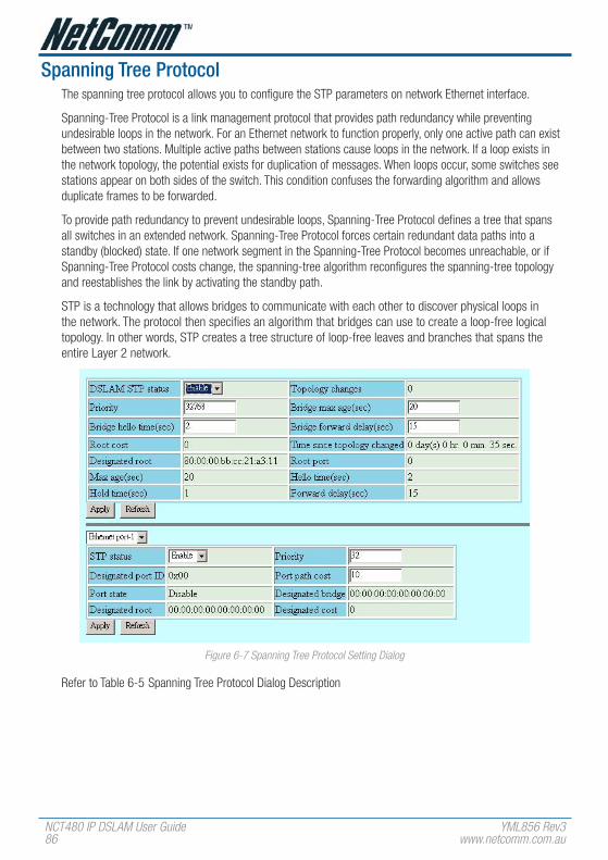
NCT480 IP DSLAM User Guide YML856 Rev386 www.netcomm.com.au
Spanning Tree ProtocolThe spanning tree protocol allows you to configure the STP parameters on network Ethernet interface.
Spanning-Tree Protocol is a link management protocol that provides path redundancy while preventing undesirable loops in the network. For an Ethernet network to function properly, only one active path can exist between two stations. Multiple active paths between stations cause loops in the network. If a loop exists in the network topology, the potential exists for duplication of messages. When loops occur, some switches see stations appear on both sides of the switch. This condition confuses the forwarding algorithm and allows duplicate frames to be forwarded.
To provide path redundancy to prevent undesirable loops, Spanning-Tree Protocol defines a tree that spans all switches in an extended network. Spanning-Tree Protocol forces certain redundant data paths into a standby (blocked) state. If one network segment in the Spanning-Tree Protocol becomes unreachable, or if Spanning-Tree Protocol costs change, the spanning-tree algorithm reconfigures the spanning-tree topology and reestablishes the link by activating the standby path.
STP is a technology that allows bridges to communicate with each other to discover physical loops in the network. The protocol then specifies an algorithm that bridges can use to create a loop-free logical topology. In other words, STP creates a tree structure of loop-free leaves and branches that spans the entire Layer 2 network.
Figure 6-� Spanning Tree Protocol Setting Dialog
Refer to Table 6-5 Spanning Tree Protocol Dialog Description
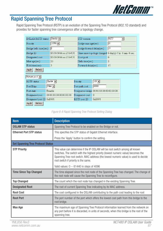
YML856 Rev3 NCT480 IP DSLAM User GuideNCT480 IP DSLAM User Guidewww.netcomm.com.au 8�
Rapid Spanning Tree ProtocolRapid Spanning Tree Protocol (RSTP) is an evolution of the Spanning Tree Protocol (802.1D standard) and provides for faster spanning tree convergence after a topology change.
Figure 6-8 Rapid Spanning Tree Protocol Setting Dialog
Item Description
DSLAM STP status Spanning Tree Protocol to be enabled on the Bridge or not.
ethernet Port STP status This specifies the STP status of Gigabit Ethernet interface.
Press the ‘Apply’ button to confirm the setting.
Set Spanning Tree Protocol Status
STP Priority This value can determine if the IP-DSLAM will be root switch among all known switches. The switch with the highest priority (lowest numeric value) becomes the Spanning Tree root switch. MAC address (the lowest numeric value) is used to decide root switch if priority is the same.
Valid values: 0 ~ 61440 in steps of 4096
Time Since Top Changed The time elapsed since the root node of the Spanning Tree has changed. The change of the root node will cause the Spanning Tree to reconfigure.
Top Changed The count which the root node has changed in the existing Spanning Tree.
Designated Root The root of current Spanning Tree indicating by its MAC address.
Root Cost The cost configured in the DSLAM contributing to the path cost leading to the root
Root Port The port number of the port which offers the lowest cost path from this bridge to the root bridge.
Max Age The maximum age of Spanning Tree Protocol information learned from the network on any port before it is discarded, in units of seconds, when this bridge is the root of the spanning tree.

NCT480 IP DSLAM User Guide YML856 Rev388 www.netcomm.com.au
Item Description
hello Time The value that all bridges use for HelloTime when this bridge is acting as the root.
forward Delay The value that all bridges use for Forward Delay when this bridge is acting as the root.
hold Time This time value determines the interval length during which no more than two Configuration bridge PDUs shall be transmitted by this node, in units of seconds.
Bridge Max Age The maximum age time of Spanning Tree Protocol information learned from the network on any port before it is discarded, in units of seconds.
Valid values: 6 ~ 40 (Seconds)
Bridge hello Time The amount of time between the transmission of Configuration BPDU (Bridge Protocol Data Units) by this node on any port when it is the root of the spanning tree or trying to become so, in units of second.
Valid values: 1 ~ 30 (Seconds)
Bridge forward Delay This value, measured in units of seconds, controls how fast a port changes its spanning state when moving towards the Forwarding state. The value determines how long the port stays in each of the Listening and Learning states, which precede the Forwarding state. This value is also used, when a topology change has been detected and is underway, to age all dynamic entries in the Forwarding Database.
Valid values: 4 ~ 30 (Seconds)
Press the ‘Apply’ button to confirm the setting.
Table 6-5 Spanning Tree Protocol Dialog Description

YML856 Rev3 NCT480 IP DSLAM User GuideNCT480 IP DSLAM User Guidewww.netcomm.com.au 8�
ChAPTeR 7 DIAGNOSTIC MeNUThe diagnostic menu provides test function from ADSL physical layer to ATM layer.
This chapter contains the following sections:
• DSL Bin Information
• ATM OAM Test
• ADSL2 DELT Test
DSL Bin InformationThe allocation table shows both upstream and downstream bin bits and bin SNR status.
Figure �-1 DSL Bin Information Dialog
Table 7-1 describes the bin allocation tap items.
Item Description
Get Press ‘Get’ button to get the DSL bin information, then press others button to show.
Upstream Bin Bits Number of downstream bits/ bin for the bin indexed by this element of the string. The 0th element contains the number of bits per bin for 0, through the 31st element, which contains the number bits for bin 31. (upstream)
Upstream Bin SNR The DELT-related parameter that provides an array of real downstream SNR (f) values in dB (Not available for ADSL and ADSL2plus)
Downstream Bin Bits Number of upstream bits/ bin for the bin indexed by this element of the string. The 0th element contains the number of bits per bin for 0, through the 31st element, which contains the number bits for bin 31. (Downstream)
Downstream Bin SNR The DELT-related parameter that provides an array of real upstream SNR (f) values in dB (Not available for ADSL and ADSL2plus)
Table �-1 DSL Bin Information Dialog

NCT480 IP DSLAM User Guide YML856 Rev3�0 www.netcomm.com.au
ATM OAM TestThe ATM OAM test generates the ATM F5 loop-back to diagnose the ADSL port interface.
Operation Administration and Maintenance (OA&M) - OA&M is defined for supervision, testing, and performance monitoring. It uses loop-back for maintenance and ITU TS standard CMIP, with organization into 5 hierarchical levels: Virtual Channel (F5 - Between VC endpoints), Virtual Path (F4- between VP endpoints), and Transmission Path (F3- Between elements that perform assembling, disassembling of payload, header, or control), Digital Section (F2 Between section end-points, performs frame synchronization) and Regenerator Section (F1- Between regeneration sections).
Figure �-� ATM OAM Test Dialog
Table 7-2 describes the OAM test field items.
Item Description
Port(vpi/vci) Loop-back source id assigned to the ATM port. The ATM port will respond to all loop-back cells, which carry this OAM id. This parameter specifies the interface, virtual path, and virtual circuit for which information is desired.
Result Use this command to display result of previous OAM loopback command. This specifies the result of the loop back test. It may be Result Unavailable, Seg Succeeded, Seg Failed, E2e Succeeded, E2e Failed, Test Aborted, or Test In Progress.
Table �-� ATM OAM Test Dialog
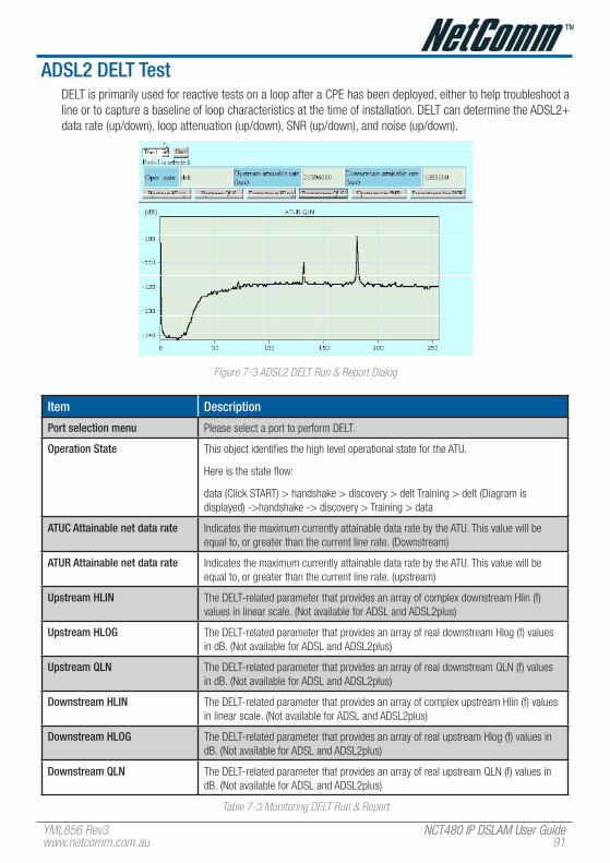
YML856 Rev3 NCT480 IP DSLAM User GuideNCT480 IP DSLAM User Guidewww.netcomm.com.au �1
ADSL2 DeLT TestDELT is primarily used for reactive tests on a loop after a CPE has been deployed, either to help troubleshoot a line or to capture a baseline of loop characteristics at the time of installation. DELT can determine the ADSL2+ data rate (up/down), loop attenuation (up/down), SNR (up/down), and noise (up/down).
Figure �-3 ADSL� DELT Run & Report Dialog
Item Description
Port selection menu Please select a port to perform DELT.
Operation State This object identifies the high level operational state for the ATU.
Here is the state flow:
data (Click START) > handshake > discovery > delt Training > delt (Diagram is displayed) ->handshake -> discovery > Training > data
ATUC Attainable net data rate Indicates the maximum currently attainable data rate by the ATU. This value will be equal to, or greater than the current line rate. (Downstream)
ATUR Attainable net data rate Indicates the maximum currently attainable data rate by the ATU. This value will be equal to, or greater than the current line rate. (upstream)
Upstream hLIN The DELT-related parameter that provides an array of complex downstream Hlin (f) values in linear scale. (Not available for ADSL and ADSL2plus)
Upstream hLOG The DELT-related parameter that provides an array of real downstream Hlog (f) values in dB. (Not available for ADSL and ADSL2plus)
Upstream QLN The DELT-related parameter that provides an array of real downstream QLN (f) values in dB. (Not available for ADSL and ADSL2plus)
Downstream hLIN The DELT-related parameter that provides an array of complex upstream Hlin (f) values in linear scale. (Not available for ADSL and ADSL2plus)
Downstream hLOG The DELT-related parameter that provides an array of real upstream Hlog (f) values in dB. (Not available for ADSL and ADSL2plus)
Downstream QLN The DELT-related parameter that provides an array of real upstream QLN (f) values in dB. (Not available for ADSL and ADSL2plus)
Table �-3 Monitoring DELT Run & Report
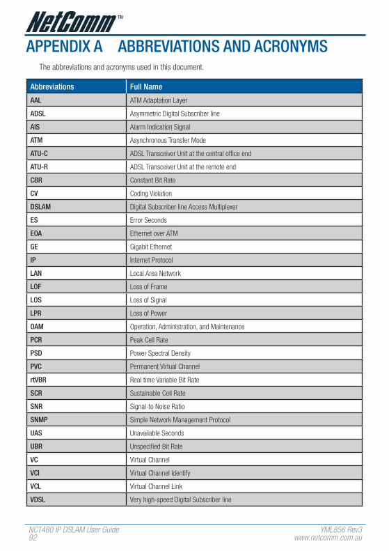
NCT480 IP DSLAM User Guide YML856 Rev3�� www.netcomm.com.au
APPeNDIx A ABBRevIATIONS AND ACRONyMSThe abbreviations and acronyms used in this document.
Abbreviations full Name
AAL ATM Adaptation Layer
ADSL Asymmetric Digital Subscriber line
AIS Alarm Indication Signal
ATM Asynchronous Transfer Mode
ATU-C ADSL Transceiver Unit at the central office end
ATU-R ADSL Transceiver Unit at the remote end
CBR Constant Bit Rate
Cv Coding Violation
DSLAM Digital Subscriber line Access Multiplexer
eS Error Seconds
eOA Ethernet over ATM
Ge Gigabit Ethernet
IP Internet Protocol
LAN Local Area Network
LOf Loss of Frame
LOS Loss of Signal
LPR Loss of Power
OAM Operation, Administration, and Maintenance
PCR Peak Cell Rate
PSD Power Spectral Density
PvC Permanent Virtual Channel
rtvBR Real time Variable Bit Rate
SCR Sustainable Cell Rate
SNR Signal-to Noise Ratio
SNMP Simple Network Management Protocol
UAS Unavailable Seconds
UBR Unspecified Bit Rate
vC Virtual Channel
vCI Virtual Channel Identify
vCL Virtual Channel Link
vDSL Very high-speed Digital Subscriber line

YML856 Rev3 NCT480 IP DSLAM User GuideNCT480 IP DSLAM User Guidewww.netcomm.com.au �3
Abbreviations full Name
vLAN Virtual Local Area Network
vP Virtual Path
vPI Virtual Path Identifier
vTU-O VDSL Transmission Unit at the Optical network interface
vTU-R VDSL Transmission Unit at the remote end
WAN Wide Area Network
xDSL ADSL/VDSL
Table A-1 Abbreviations and Acronyms Table

NCT480 IP DSLAM User Guide YML856 Rev3�4 www.netcomm.com.au
APPeNDIx B SySTeM CONNeCTOR PIN-OUTSNCT480 System connector Pin-outs contains RJ-21 Subscriber connector, RJ-45 to RS-232 DB-9 adapter local craft management, and RJ-45 GE Network uplink and Management interface.
RJ-21 xDSL Connector Port MappingThe female RJ-21 (Champ) subscriber connectors are located at the rear of NCT480 box chassis.
Table A-1 shows ADSL and POTS connectors correspond to ports on ADSL – J1/J2, Line – J1/J2, and POTS J1/J2.
Figure A-1 RJ-�1 Connector
Line Port / POTS Port Champ Pin
J1 J2 Tip Ring
1 25 1 26
2 26 2 27
3 27 3 28
4 28 4 29
5 29 5 30
6 30 6 31
7 31 7 32
8 32 8 33
9 33 9 34
10 34 10 35
11 35 11 36
12 36 12 37
13 37 13 38
14 38 14 39
15 39 15 40
16 40 16 41
17 41 17 42
18 42 18 43
19 43 19 44

YML856 Rev3 NCT480 IP DSLAM User GuideNCT480 IP DSLAM User Guidewww.netcomm.com.au �5
Line Port / POTS Port Champ Pin
J1 J2 Tip Ring
20 44 20 45
21 45 21 46
22 46 22 47
23 47 23 48
24 48 24 49
None None 25 50
Table A-1 RJ-�1 Connector Pin Assignment
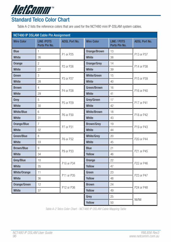
NCT480 IP DSLAM User Guide YML856 Rev3�6 www.netcomm.com.au
Standard Telco Color ChartTable A-2 lists the reference colors that are used for the NCT480 mini IP-DSLAM system cables.
NCT480 IP DSLAM Cable Pin Assignment
Wire Color LINe /POTS Ports Pin No.
ADSL Port No. Wire Color LINe / POTS Ports Pin No.
ADSL Port No.
Blue 1P1 or P25
Orange/Brown 13P13 or P37
White 26 White 38
Orange 2P2 or P26
Orange/Grey 14P14 or P38
White 27 White 39
Green 3P3 or P27
White/Green 15P15 or P39
White 28 White 40
Brown 4P4 or P28
Green/Brown 16P16 or P40
White 29 White 41
Grey 5P5 or P29
Grey/Green 17P17 or P41
White 30 White 42
White/Blue 6P6 or P30
White/Brown 18P18 or P42
White 31 White 43
Orange/Blue 7P7 or P31
Brown/Grey 19P19 or P43
White 32 White 44
Green/Blue 8P8 or P32
White/Grey 20P20 or P44
White 33 White 45
Brown/Blue 9P9 or P33
Blue 21P21 or P45
White 34 yellow 46
Grey/Blue 10P10 or P34
Orange 22P22 or P46
White 35 yellow 47
White/Orange 11P11 or P35
Green 23P23 or P47
White 36 yellow 48
Orange/Green 12P12 or P36
Brown 24P24 or P48
White 37 yellow 49
Grey 25Nil/Nil
yellow 50
Table A-� Telco Color Chart - NCT480 IP DSLAM Cable Mapping Table

YML856 Rev3 NCT480 IP DSLAM User GuideNCT480 IP DSLAM User Guidewww.netcomm.com.au ��
RJ-45 Management ethernet Connector Pin-OutsThe Management Ethernet port, a 10/100 Base-T interface with RJ-45 receptacle connector is on the NCT480 faceplate.
It is used to connect the NCT480 to the management station. Table A-3 shows the pin assignments of RJ-45 GE Network uplink interface.
Figure A-� RJ-45 GE Connector
Pine Description
1 TP0 +
2 TP0 -
3 TP1 +
4 TP2 +
5 TP2 -
6 TP1 -
7 TP3 +
8 TP3 -
Table A-3 RJ-45 GE Connector Pin Assignment

NCT480 IP DSLAM User Guide YML856 Rev3�8 www.netcomm.com.au
Local Console Connector Pin-OutsRJ-45 connector on the NCT480 faceplate is use for Console management. A RJ-45 to DB-9 Female adaptor is used to connect on PC’s COM port. Table A-4 lists the pin assignment between RJ-45 and DB-9 interface.
Figure A-3 RJ45 to DB-� Adaptor
DB-9 DB-9 Signal RJ-45 signal RJ-45
1 2
2 TxD TxD 6
3 RxD RxD 5
4 DTE Ready DTE Ready 1
5 GND GNDF 4
6 DCE Ready DCE Ready 3
7 CTS CTS 7
8 RTS RTS 8
9
Table A-4 RJ45 to DB-� Pint Assignment

YML856 Rev3 NCT480 IP DSLAM User GuideNCT480 IP DSLAM User Guidewww.netcomm.com.au ��
APPeNDIx C LeGAL & ReGULATORy INfORMATIONThis manual is copyright. Apart from any fair dealing for the purposes of private study, research, criticism or review, as permitted under the Copyright Act, no part may be reproduced, stored in a retrieval system or transmitted in any form, by any means, be it electronic, mechanical, recording or otherwise, without the prior written permission of NetComm Limited. NetComm Limited accepts no liability or responsibility, for consequences arising from the use of this product.
NetComm Limited reserves the right to change the specifications and operating details of this product without notice.
NetComm is a registered trademark of NetComm Limited.
All other trademarks are acknowledged the property of their respective owners.
Customer InformationACA (Australian Communications Authority) requires you to be aware of the following information and warnings:
(1) This unit shall be connected to the Telecommunication Network through a line cord which meets the requirements of the ACA TS008 Standard.
(2) This equipment has been tested and found to comply with the Standards for C-Tick and or A-Tick as set by the ACA . These standards are designed to provide reasonable protection against harmful interference in a residential installation. This equipment generates, uses, and can radiate radio noise and, if not installed and used in accordance with the instructions detailed within this manual, may cause interference to radio communications. However, there is no guarantee that interference will not occur with the installation of this product in your home or office. If this equipment does cause some degree of interference to radio or television reception, which can be determined by turning the equipment off and on, we encourage the user to try to correct the interference by one or more of the following measures:
• Change the direction or relocate the receiving antenna.
• Increase the separation between this equipment and the receiver.
• Connect the equipment to an alternate power outlet on a different power circuit from that to which the receiver/TV is connected.
• Consult an experienced radio/TV technician for help.
(3) The power supply that is provided with this unit is only intended for use with this product. Do not use this power supply with any other product or do not use any other power supply that is not approved for use with this product by NetComm. Failure to do so may cause damage to this product, fire or result in personal injury.

NCT480 IP DSLAM User Guide YML856 Rev3100 www.netcomm.com.au
Product WarrantyThe warranty is granted on the following conditions:
1. This warranty extends to the original purchaser (you) and is not transferable;
2. This warranty shall not apply to software programs, batteries, power supplies, cables or other accessories supplied in or with the product;
3. The customer complies with all of the terms of any relevant agreement with NetComm and any other reasonable requirements of NetComm including producing such evidence of purchase as NetComm may require;
4. The cost of transporting product to and from NetComm’s nominated premises is your responsibility; and,
5. NetComm does not have any liability or responsibility under this warranty where any cost, loss, injury or damage of any kind, whether direct, indirect, consequential, incidental or otherwise arises out of events beyond NetComm’s reasonable control. This includes but is not limited to: acts of God, war, riot, embargoes, acts of civil or military authorities, fire, floods, electricity outages, lightning, power surges, or shortages of materials or labour.
6. The customer is responsible for the security of their computer and network at all times. Security features may be disabled within the factory default settings. NetComm recommends that you enable these features to enhance your security.
The warranty is automatically voided if:
1. You, or someone else, use the product, or attempts to use it, other than as specified by NetComm;
2. The fault or defect in your product is the result of a voltage surge subjected to the product either by the way of power supply or communication line, whether caused by thunderstorm activity or any other cause(s);
3. The fault is the result of accidental damage or damage in transit, including but not limited to liquid spillage;
4. Your product has been used for any purposes other than that for which it is sold, or in any way other than in strict accordance with the user manual supplied;
5. Your product has been repaired or modified or attempted to be repaired or modified, other than by a qualified person at a service centre authorised by NetComm; and,
6. The serial number has been defaced or altered in any way or if the serial number plate has been removed.
Limitations of WarrantyThe Trade Practices Act 1974 and corresponding State and Territory Fair Trading Acts or legalisation of another Government (“the relevant acts”) in certain circumstances imply mandatory conditions and warranties which cannot be excluded. This warranty is in addition to and not in replacement for such conditions and warranties.
To the extent permitted by the Relevant Acts, in relation to your product and any other materials provided with the product (“the Goods”) the liability of NetComm under the Relevant Acts is limited at the option of NetComm to:
• Replacement of the Goods; or
• Repair of the Goods; or
• Payment of the cost of replacing the Goods; or
• Payment of the cost of having the Goods repaired.
All NetComm ACN 002 490 486 products have a standard 12 months warranty from date of purchase. However some products have an extended warranty option (refer to packaging). To be eligible for the extended warranty you must supply the requested warranty information to NetComm within 30 days of the original purchase by registering on-line via the NetComm web site at
www.netcomm.com.au

YML856 Rev3 NCT480 IP DSLAM User GuideNCT480 IP DSLAM User Guidewww.netcomm.com.au 101

NCT480 IP DSLAM User Guide YML856 Rev310� www.netcomm.com.au

YML856 Rev3 NCT480 IP DSLAM User GuideNCT480 IP DSLAM User Guidewww.netcomm.com.au 103

NCT480 IP DSLAM User Guide YML856 Rev3104 www.netcomm.com.au

YML856 Rev3 NCT480 IP DSLAM User GuideNCT480 IP DSLAM User Guidewww.netcomm.com.au 105

NCT480 IP DSLAM User Guide YML856 Rev3106 www.netcomm.com.au

YML856 Rev3 NCT480 IP DSLAM User GuideNCT480 IP DSLAM User Guidewww.netcomm.com.au 10�

NCT480 IP DSLAM User Guide YML856 Rev3108 www.netcomm.com.au

YML856 Rev3 NCT480 IP DSLAM User GuideNCT480 IP DSLAM User Guidewww.netcomm.com.au 10�

NCT480 IP DSLAM User Guide YML856 Rev3110 www.netcomm.com.au

YML856 Rev3 NCT480 IP DSLAM User GuideNCT480 IP DSLAM User Guidewww.netcomm.com.au 111

NCT480 IP DSLAM User Guide YML856 Rev311� www.netcomm.com.au

YML856 Rev3 NCT480 IP DSLAM User GuideNCT480 IP DSLAM User Guidewww.netcomm.com.au 113

NCT480 IP DSLAM User Guide YML856 Rev3114 www.netcomm.com.au

YML856 Rev3 NCT480 IP DSLAM User GuideNCT480 IP DSLAM User Guidewww.netcomm.com.au 115

NCT480 IP DSLAM User Guide YML856 Rev3116 www.netcomm.com.au

YML856 Rev3 NCT480 IP DSLAM User GuideNCT480 IP DSLAM User Guidewww.netcomm.com.au 11�

NCT480 IP DSLAM User Guide YML856 Rev3118 www.netcomm.com.au

YML856 Rev3 NCT480 IP DSLAM User GuideNCT480 IP DSLAM User Guidewww.netcomm.com.au 11�

NCT480 IP DSLAM User Guide YML856 Rev31�0 www.netcomm.com.au

YML856 Rev3 NCT480 IP DSLAM User GuideNCT480 IP DSLAM User Guidewww.netcomm.com.au 1�1

NCT480 IP DSLAM User Guide YML856 Rev31�� www.netcomm.com.au

YML856 Rev3 NCT480 IP DSLAM User GuideNCT480 IP DSLAM User Guidewww.netcomm.com.au 1�3

NCT480 IP DSLAM User Guide YML856 Rev31�4 www.netcomm.com.au

YML856 Rev3 NCT480 IP DSLAM User GuideNCT480 IP DSLAM User Guidewww.netcomm.com.au 1�5

NCT480 IP DSLAM User Guide YML856 Rev31�6 www.netcomm.com.au

YML856 Rev3 NCT480 IP DSLAM User GuideNCT480 IP DSLAM User Guidewww.netcomm.com.au 1��

NCT480 IP DSLAM User Guide YML856 Rev31�8 www.netcomm.com.au

YML856 Rev3 NCT480 IP DSLAM User GuideNCT480 IP DSLAM User Guidewww.netcomm.com.au 1��

NCT480 IP DSLAM User Guide YML856 Rev3130 www.netcomm.com.au

YML856 Rev3 NCT480 IP DSLAM User GuideNCT480 IP DSLAM User Guidewww.netcomm.com.au 131

NCT480 IP DSLAM User Guide YML856 Rev313� www.netcomm.com.au

YML856 Rev3 NCT480 IP DSLAM User GuideNCT480 IP DSLAM User Guidewww.netcomm.com.au 133

NCT480 IP DSLAM User Guide YML856 Rev3134 www.netcomm.com.au

YML856 Rev3 NCT480 IP DSLAM User GuideNCT480 IP DSLAM User Guidewww.netcomm.com.au 135

NCT480 IP DSLAM User Guide YML856 Rev3136 www.netcomm.com.au

YML856 Rev3 NCT480 IP DSLAM User GuideNCT480 IP DSLAM User Guidewww.netcomm.com.au 13�

NCT480 IP DSLAM User Guide YML856 Rev3138 www.netcomm.com.au

YML856 Rev3 NCT480 IP DSLAM User GuideNCT480 IP DSLAM User Guidewww.netcomm.com.au 13�

NCT480 IP DSLAM User Guide YML856 Rev3140 www.netcomm.com.au

YML856 Rev3 NCT480 IP DSLAM User GuideNCT480 IP DSLAM User Guidewww.netcomm.com.au 141

NCT480 IP DSLAM User Guide YML856 Rev314� www.netcomm.com.au

YML856 Rev3 NCT480 IP DSLAM User GuideNCT480 IP DSLAM User Guidewww.netcomm.com.au 143

NCT480 IP DSLAM User Guide YML856 Rev3144 www.netcomm.com.au

YML856 Rev3 NCT480 IP DSLAM User GuideNCT480 IP DSLAM User Guidewww.netcomm.com.au 145

NCT480 IP DSLAM User Guide YML856 Rev3146 www.netcomm.com.au

YML856 Rev3 NCT480 IP DSLAM User GuideNCT480 IP DSLAM User Guidewww.netcomm.com.au 14�

NCT480 IP DSLAM User Guide YML856 Rev3148 www.netcomm.com.au

YML856 Rev3 NCT480 IP DSLAM User GuideNCT480 IP DSLAM User Guidewww.netcomm.com.au 14�

NCT480 IP DSLAM User Guide YML856 Rev3150 www.netcomm.com.au

YML856 Rev3 NCT480 IP DSLAM User GuideNCT480 IP DSLAM User Guidewww.netcomm.com.au 151

NCT480 IP DSLAM User Guide YML856 Rev315� www.netcomm.com.au

YML856 Rev3 NCT480 IP DSLAM User GuideNCT480 IP DSLAM User Guidewww.netcomm.com.au 153

NCT480 IP DSLAM User Guide YML856 Rev3154 www.netcomm.com.au

YML856 Rev3 NCT480 IP DSLAM User GuideNCT480 IP DSLAM User Guidewww.netcomm.com.au 155

NCT480 IP DSLAM User Guide YML856 Rev3156 www.netcomm.com.au

YML856 Rev3 NCT480 IP DSLAM User GuideNCT480 IP DSLAM User Guidewww.netcomm.com.au 15�

NCT480 IP DSLAM User Guide YML856 Rev3158 www.netcomm.com.au

YML856 Rev3 NCT480 IP DSLAM User GuideNCT480 IP DSLAM User Guidewww.netcomm.com.au 15�

NCT480 IP DSLAM User Guide YML856 Rev3160 www.netcomm.com.au

YML856 Rev3 NCT480 IP DSLAM User GuideNCT480 IP DSLAM User Guidewww.netcomm.com.au 161

NCT480 IP DSLAM User Guide YML856 Rev316� www.netcomm.com.au

YML856 Rev3 NCT480 IP DSLAM User GuideNCT480 IP DSLAM User Guidewww.netcomm.com.au 163

Contact InformationIf you have any technical difficulties with your product, please do not hesitate to contact NetComm’s Customer Support Department.
Email: [email protected]
www.netcomm.com.auNote: NetComm Technical Support for this product only covers the basic installation and features outlined in the Quick Start Guide. For further information regarding the advanced features of this product, please refer to the configuring sections in this User Guide or contact a Network Specialist.
NetComm Limited ABN 85 002 490 486
PO Box 1200, Lane Cove NSW 2066 AustraliaE – [email protected] W – www.netcomm.com.au