Embed Size (px)
Citation preview
Management User Guide
IP DSLAM
NetComm NCT240 Management Guide Release 1.0
Table of Content
1. INTRODUCTION ..............................................................................................................................5
1.1 FEATURES........................................................................................................................................6 1.2 BASIC OPERATING INFORMATION .....................................................................................................7
1.2.1 Default username and Password .............................................................................................7 1.2.2 Default IP addresses................................................................................................................7 1.2.3 Default profile..........................................................................................................................7
2. CONFIGURING THE SWITCH BY WEB INTERFACE..............................................................8
2.1 SYSTEM ...........................................................................................................................................8 2.1.1 System Info...............................................................................................................................8 2.1.2 System log................................................................................................................................9 2.1.3 SNMP setup ...........................................................................................................................10 2.1.4 General setup.........................................................................................................................10 2.1.5 Reboot.................................................................................................................................... 11 2.1.6 Synchronization with Time server (SNTP) .............................................................................12 2.1.7 User Management..................................................................................................................12 2.1.8 Log out...................................................................................................................................12 2.1.9 Server services.......................................................................................................................13 2.1.10 Alarm ...................................................................................................................................13 2.1.11 Daisy control........................................................................................................................13 2.1.12 Software upgrade and Configuration backup......................................................................14
2.2 ADSL............................................................................................................................................15 2.2.1 xDSL port setup .....................................................................................................................15
2.2.1.1 Map profile ............................................................................15 2.2.1.2 copy Settings to other ports .......................................................16 2.2.1.3 PVC Map (single and Multiple PVC setup).......................................16 2.2.1.4 PVC show ...............................................................................17 2.2.1.5 PVC delete .............................................................................17
2.2.2 Multiple port xDSL set up......................................................................................................18 2.2.3 xDSL profiles .........................................................................................................................19
2.2.3.1 Port profile ............................................................................19 2.2.3.2 VC profile ..............................................................................19 2.2.3.3 Alarm profile ..........................................................................20 2.2.3.4 Map alarm profile ....................................................................20
2.2.4 Line Diagnostic – DELT........................................................................................................21 2.3 SWITCH .........................................................................................................................................21
2.3.1 VLAN .....................................................................................................................................21
1
NetComm NCT240 Management Guide Release 1.0
2.3.2 Ethernet Port Setting .............................................................................................................22 2.3.3 MAC management .................................................................................................................23 2.3.4 IGMP snooping......................................................................................................................24 2.3.5 Port authentication 802.1x ....................................................................................................24 2.3.6 Queue MAP ...........................................................................................................................25 2.3.7 DHCP relay – option 82 ........................................................................................................26 2.3.8 Loop test ................................................................................................................................26
2.4 STATUS ..........................................................................................................................................26 2.4.1 Channel status .......................................................................................................................26 2.4.2 Line status..............................................................................................................................27 2.4.4 Line state ...............................................................................................................................27
2.5 IP...................................................................................................................................................28 2.5.1 IP setup..................................................................................................................................28 2.5.2 ARP table Display and flush..................................................................................................28 2.5.3 PING function........................................................................................................................29 2.5.4 VLAN (For management ) .....................................................................................................29
2.6 PERFORMANCE ..............................................................................................................................29 2.6.1 ADSL performance ................................................................................................................29
2.7 STATISTICS.....................................................................................................................................30 2.7.1 Gigabit Ethernet port counters..............................................................................................30 2.7.2 Utopia counter.......................................................................................................................30 2.7.3 VCC counter ..........................................................................................................................30 2.7.4 Ether port counter .................................................................................................................31 2.7.5 Vcencap counter ....................................................................................................................31 2.7.6 Excpetion counter ..................................................................................................................31
2.8 CONFIGURATION............................................................................................................................32 2.8.1 Configuration save ................................................................................................................32 2.8.2 Restore ...................................................................................................................................32
3. CONFIGURING NCT240 BY CLI INTERFACE .........................................................................33
LOG IN PROCESS..................................................................................................................................35 COMMAND FORMAT.............................................................................................................................37 SYSTEM: ...........................................................................................................................................38
daisycontrol ....................................................................................................................................38 Update ............................................................................................................................................39 Info .................................................................................................................................................40 User ................................................................................................................................................40 Reboot.............................................................................................................................................41 SNMP..............................................................................................................................................42
2

NetComm NCT240 Management Guide Release 1.0
Server..............................................................................................................................................42 Syslog..............................................................................................................................................43 Time ................................................................................................................................................44 Date ................................................................................................................................................44 Timeserver ......................................................................................................................................45 Alarm..............................................................................................................................................46
ADSL: ................................................................................................................................................47 Enable.............................................................................................................................................47 Disable............................................................................................................................................48 Profile .............................................................................................................................................49 Name...............................................................................................................................................49 Line diagnostic ...............................................................................................................................50 Vcprofile .........................................................................................................................................50 Alarmprofile....................................................................................................................................51 PVC ................................................................................................................................................51
STATUS: ...............................................................................................................................................52 Chstatusget .....................................................................................................................................52 Linestatusget...................................................................................................................................53 Linestateget ....................................................................................................................................53
SWITCH:............................................................................................................................................54 Queuemap.......................................................................................................................................54 VLAN ..............................................................................................................................................55 MAC ...............................................................................................................................................55 802.1x .............................................................................................................................................56 IGMP snooping ..............................................................................................................................56 DHCP relay, option 82 ...................................................................................................................57 Eth ..................................................................................................................................................57 Looptest ..........................................................................................................................................58
IP: .......................................................................................................................................................58 show................................................................................................................................................58 Arp..................................................................................................................................................59 Set ...................................................................................................................................................59 Gateway..........................................................................................................................................60 Route...............................................................................................................................................60 Ping ................................................................................................................................................60
STATISTICS: .....................................................................................................................................61 Adsl.................................................................................................................................................61 Ethuto .............................................................................................................................................62
3

NetComm NCT240 Management Guide Release 1.0
CONFIG: ............................................................................................................................................62 Save ................................................................................................................................................63 Restore............................................................................................................................................63
4. TROUBLESHOOTING...................................................................................................................64
TROUBLESHOOTING GUIDE..................................................................................................................64
6. GLOSSARY ......................................................................................................................................66
4
NetComm NCT240 Management Guide Release 1.0
1. Introduction This document is intended for First Office Acceptance test plan for NetComm’s ADSL2+
Broadband Access Switch solution (BAS). The Netcomm NCT240 Broadband Access Switch
contains 24 ADSL2/2+ circuits to deliver high-speed data, video and voice service over
traditional twisted copper pairs by using DSL technology.
To meet the increasing demand for high-speed internet access and triple play application
services. The next generation network offers a feasible functionality of integrated services
with the most cost effective architecture. Next generation broadband access networks are
designed to provide rich video contents, DSL , POTS and VoIP services over traditional copper
wire infrastructure. These types of services will be supported on NGN architecture
simultaneously. DSL is used as the data service platform for traditional POTS technology
which is used for voice services. The multimedia and local content-rich applications can also
be easily implemented on this NGN architecture.
xDSL (Digital Subscriber Line) is a technology for delivering high-bandwidth information over
copper telephone lines. xDSL service can deliver POTS and high date rate services
simultaneously over a single twisted-wire pair. The POTS and data service are simultaneous
and independent; the xDSL data service does not affect the POTS service. xDSL uses the
bandwidth above the 4-kHz POTS frequency to transmit duplex data using digital modulation
techniques from the C.O side to the Customer Premises Equipment (CPE).
ADSL is a form of xDSL service that delivers an asymmetric data rate over a twisted copper
pair. ADSL delivers a higher rate downstream, towards the customer premises and lower rate
upstream, from the customer premises. ITU standard compliant Full-Rate ADSL2+ can deliver
data rates up to 25 Mbps downstream and 1 Mbps upstream; Full-Rate ADSL can deliver data
rates up to 8 Mbps downstream and 800 kbps upstream; G.Lite ADSL can deliver up to 1.5
Mbps downstream and 512 kbps upstream. The actual data rate depends on the length, gauge,
and condition of the twisted-wire pair, the bandwidth of the uplink depends on the data
network, and the capacity of the network service provider.
Digital Subscriber Line (DSL) dominates broadband market. The position of national telecom
operators in most countries has given the advantage in reaching out to customers with
broadband services over DSL.
5
NetComm NCT240 Management Guide Release 1.0
The NCT240 Access system contains 24 ADSL2/2+ circuits to deliver high-speed data service
over twisted copper pairs using industry standard Discrete Multi-Tone (DMT) line coding
technology. The NCT240 complies with full-rate ADSL in accordance with ANSI T1.413 Issue 2,
ITU-T G.992.1 (G.dmt), ITU-T G.992.2 (G.lite)ITU-T G.992.3 (ADSL2) and ITU G.992.5
(G.ADSL2+) protocols.
The NCT240 greatly expand broadband capabilities in the access network, enhancing the
infrastructure for emerging services. With simple in-service upgrades, service providers
obtain the capacity and Quality of Service (QoS) to support larger populations of narrowband
and broadband users. For management, NCT240 can be easily configured by SNMP, Telnet,
SSH, HTTP, HTTPS and RS-232 console.
1.1 Features
Complete Intelligent L2 switch feature Intelligent DSL interworking feature
RFC2684 MpoA VPN pass-through RFC2516 PPPoE packet forwarding.
Advanced L2+/higher layer protocol & policy control GVRP/GARP/GMRP (IEEE 802.1q) (phase2) STP/RSTP (IEEE 802.1d/w) (phase2) IGMP Snooping DHCP relay and relay agent option 82 Packet inspection and do policy control (filtering, forwarding..)
Security of authentication mechanism and encryption SSH/SSL
Rich user interface for management including security CLI/Telnet/SSH/SNMP/HTTP/S-HTTP
Variety of uplink interface SFP for 1000 Base-SX, LX, LHX and ZX. RJ45 for 1000 Base-TX. (Default)
Remote software upgrade
6
NetComm NCT240 Management Guide Release 1.0
1.2 Basic operating information
1.2.1 Default username and Password
Username: admin Password: admin
1.2.2 Default IP addresses
MGMT : (Management Ethernet port ) – 192.168.1.1 UPLINKs : 192.168.0.1
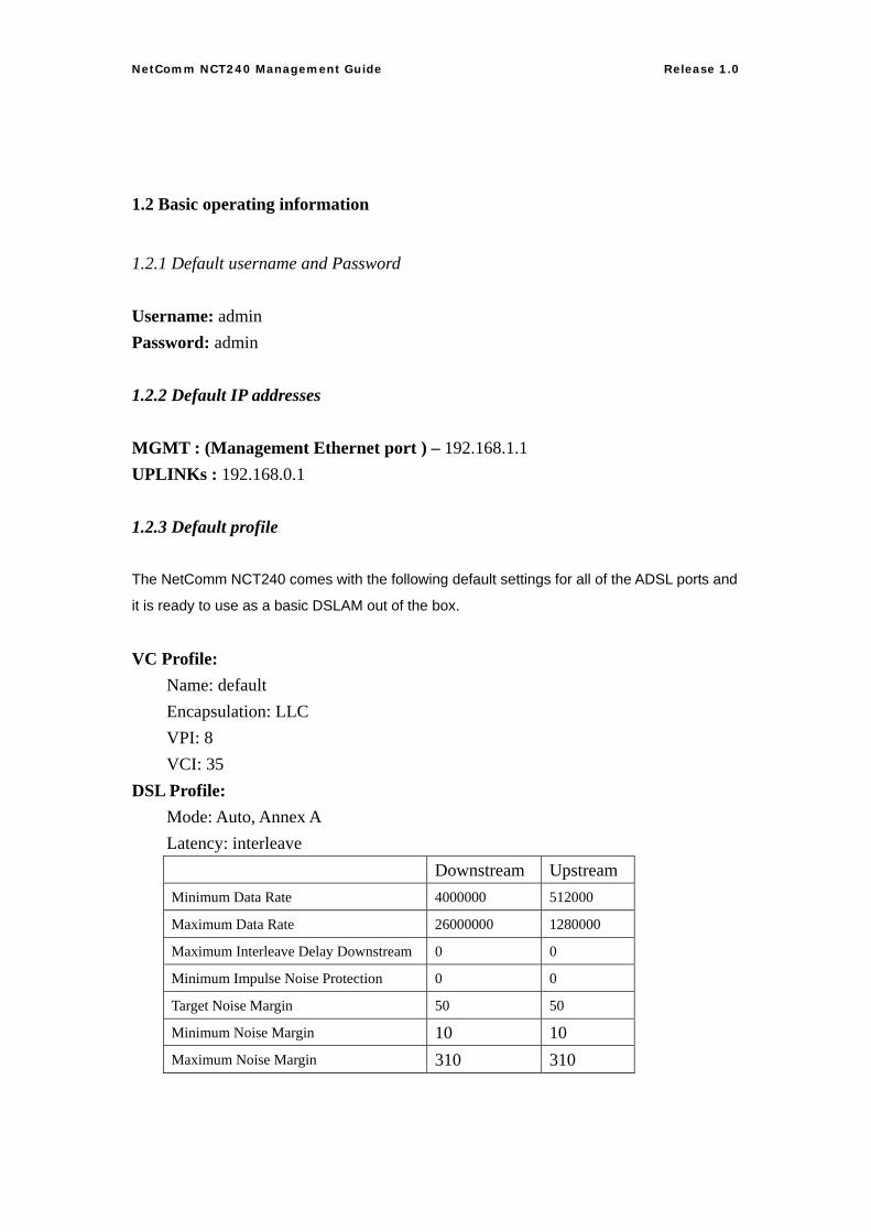
1.2.3 Default profile
The NetComm NCT240 comes with the following default settings for all of the ADSL ports and
it is ready to use as a basic DSLAM out of the box.
VC Profile: Name: default Encapsulation: LLC VPI: 8 VCI: 35
DSL Profile: Mode: Auto, Annex A Latency: interleave
Downstream Upstream Minimum Data Rate 4000000 512000 Maximum Data Rate 26000000 1280000 Maximum Interleave Delay Downstream 0 0
Minimum Impulse Noise Protection 0 0
Target Noise Margin 50 50
Minimum Noise Margin 10 10 Maximum Noise Margin 310 310
7
NetComm NCT240 Management Guide Release 1.0
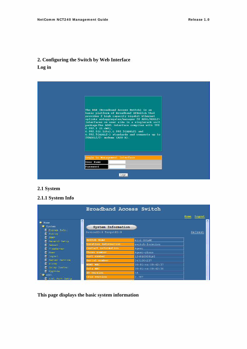
2. Configuring the Switch by Web Interface Log in
2.1 System
2.1.1 System Info
This page displays the basic system information
8
NetComm NCT240 Management Guide Release 1.0
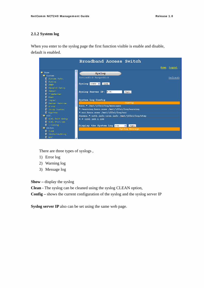
2.1.2 System log
When you enter to the syslog page the first function visible is enable and disable, default is enabled.
There are three types of syslogs , 1) Error log 2) Warning log 3) Message log
Show – display the syslog Clean - The syslog can be cleaned using the syslog CLEAN option, Config – shows the current configuration of the syslog and the syslog server IP Syslog server IP also can be set using the same web page.
9
NetComm NCT240 Management Guide Release 1.0
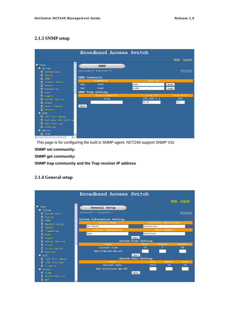
2.1.3 SNMP setup
This page is for configuring the built in SNMP agent, NCT240 support SNMP V2c
SNMP set community:
SNMP get community:
SNMP trap community and the Trap receiver IP address
2.1.4 General setup
10
NetComm NCT240 Management Guide Release 1.0
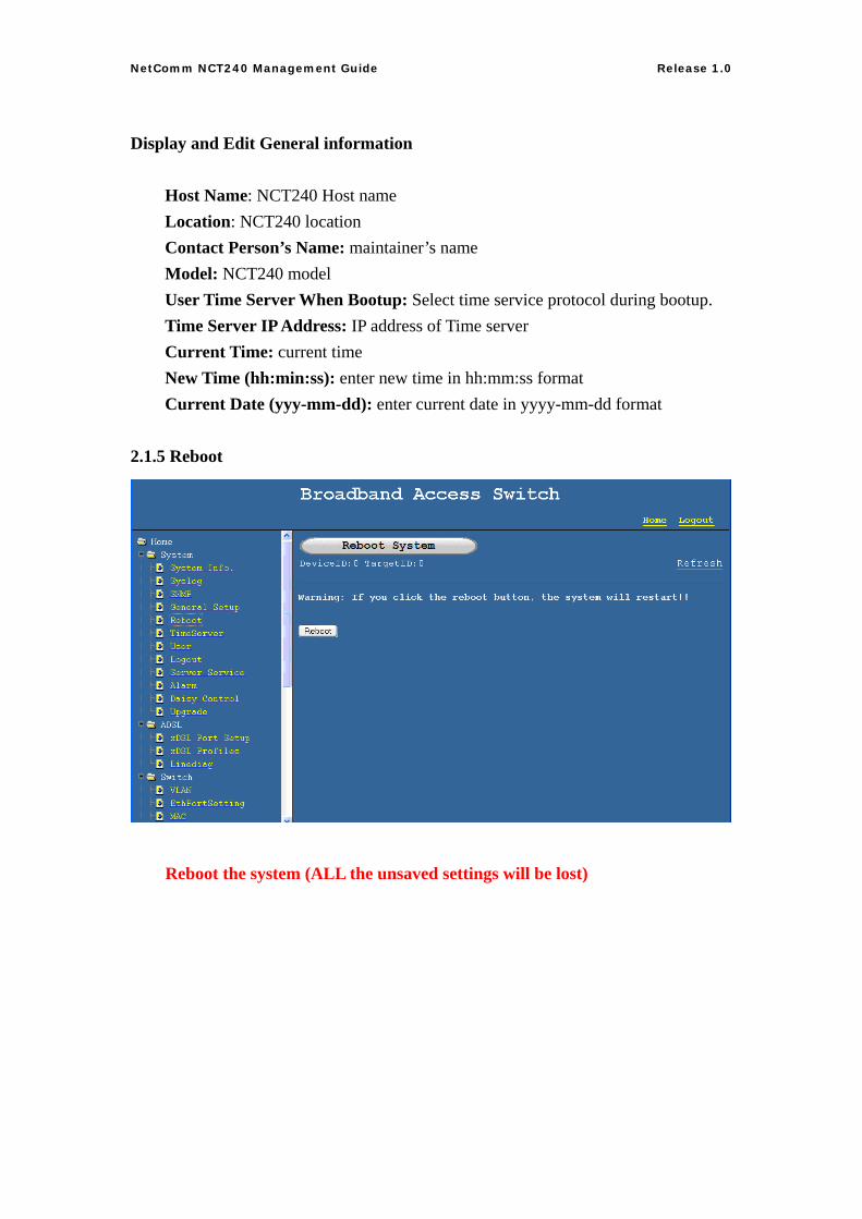
Display and Edit General information Host Name: NCT240 Host name Location: NCT240 location Contact Person’s Name: maintainer’s name Model: NCT240 model User Time Server When Bootup: Select time service protocol during bootup. Time Server IP Address: IP address of Time server Current Time: current time New Time (hh:min:ss): enter new time in hh:mm:ss format Current Date (yyy-mm-dd): enter current date in yyyy-mm-dd format 2.1.5 Reboot
Reboot the system (ALL the unsaved settings will be lost)
11
NetComm NCT240 Management Guide Release 1.0
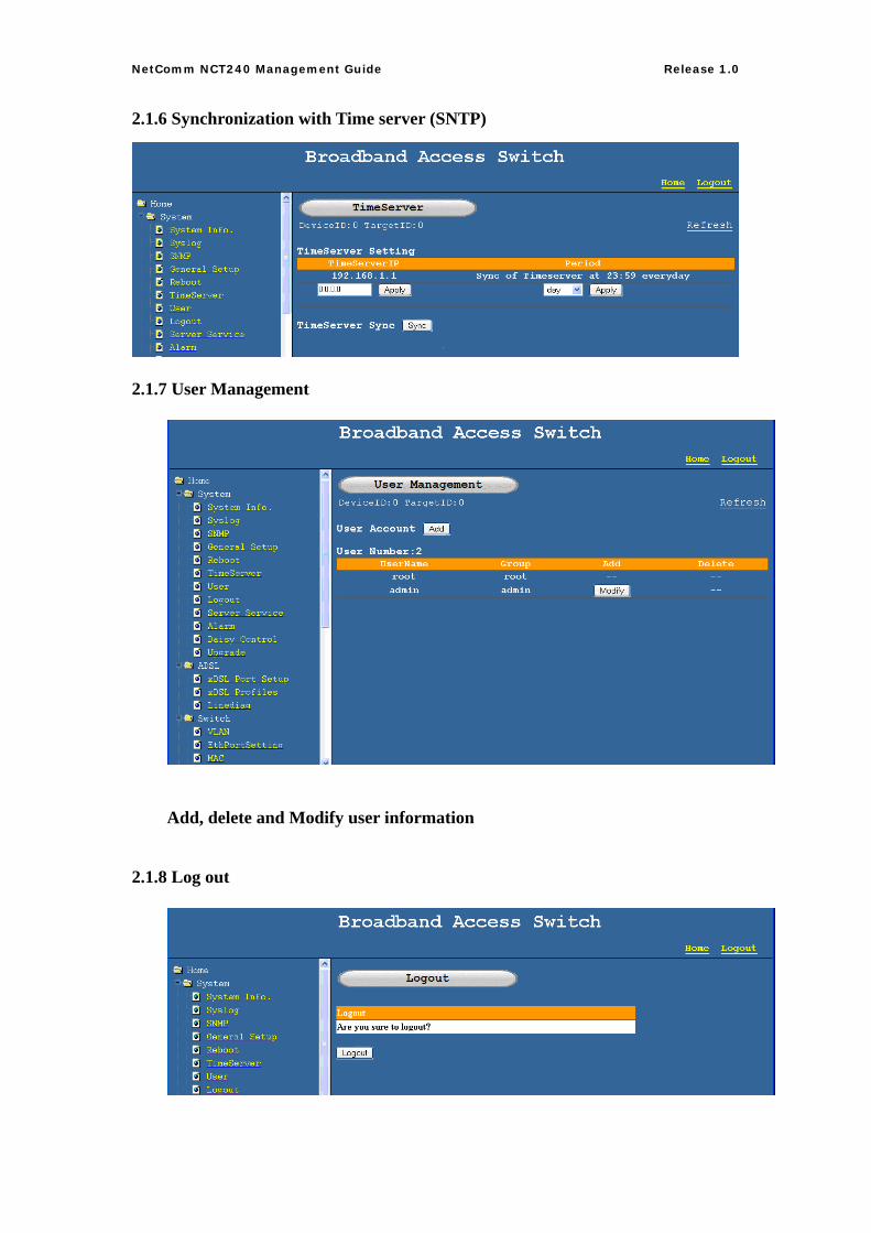
2.1.6 Synchronization with Time server (SNTP)
2.1.7 User Management
Add, delete and Modify user information
2.1.8 Log out
12
NetComm NCT240 Management Guide Release 1.0
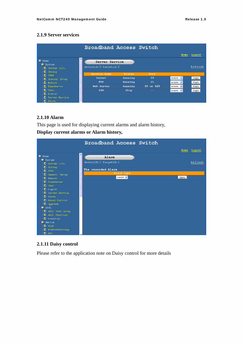
2.1.9 Server services
2.1.10 Alarm This page is used for displaying current alarms and alarm history, Display current alarms or Alarm history,
2.1.11 Daisy control
Please refer to the application note on Daisy control for more details
13
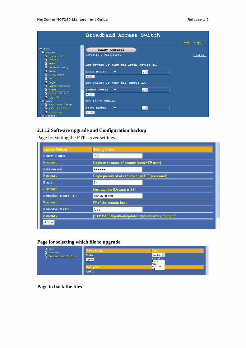
NetComm NCT240 Management Guide Release 1.0
2.1.12 Software upgrade and Configuration backup Page for setting the FTP server settings
Page for selecting which file to upgrade
Page to back the files
14
NetComm NCT240 Management Guide Release 1.0
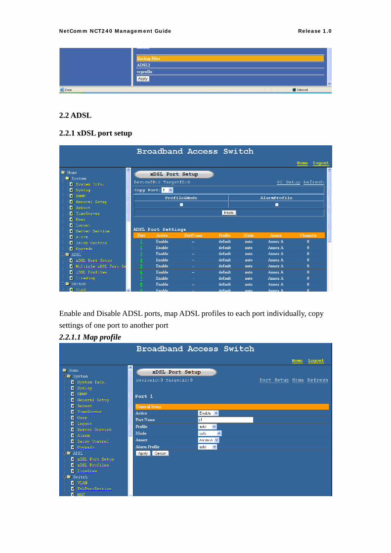
2.2 ADSL
2.2.1 xDSL port setup
Enable and Disable ADSL ports, map ADSL profiles to each port individually, copy settings of one port to another port 2.2.1.1 Map profile
15
NetComm NCT240 Management Guide Release 1.0
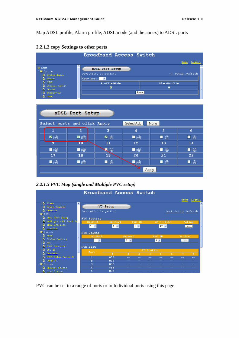
Map ADSL profile, Alarm profile, ADSL mode (and the annex) to ADSL ports 2.2.1.2 copy Settings to other ports
2.2.1.3 PVC Map (single and Multiple PVC setup)
PVC can be set to a range of ports or to Individual ports using this page.
16
NetComm NCT240 Management Guide Release 1.0
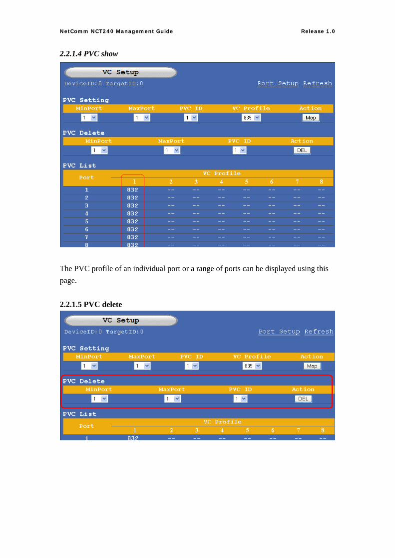
2.2.1.4 PVC show
The PVC profile of an individual port or a range of ports can be displayed using this page. 2.2.1.5 PVC delete
17
NetComm NCT240 Management Guide Release 1.0
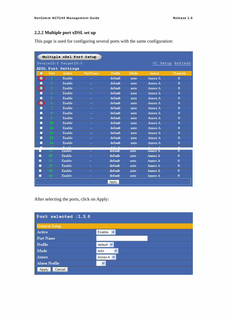
2.2.2 Multiple port xDSL set up
This page is used for configuring several ports with the same configuration:
After selecting the ports, click on Apply:
18
NetComm NCT240 Management Guide Release 1.0
2.2.3 xDSL profiles
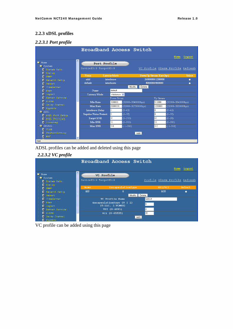
2.2.3.1 Port profile
ADSL profiles can be added and deleted using this page 2.2.3.2 VC profile
VC profile can be added using this page
19
NetComm NCT240 Management Guide Release 1.0
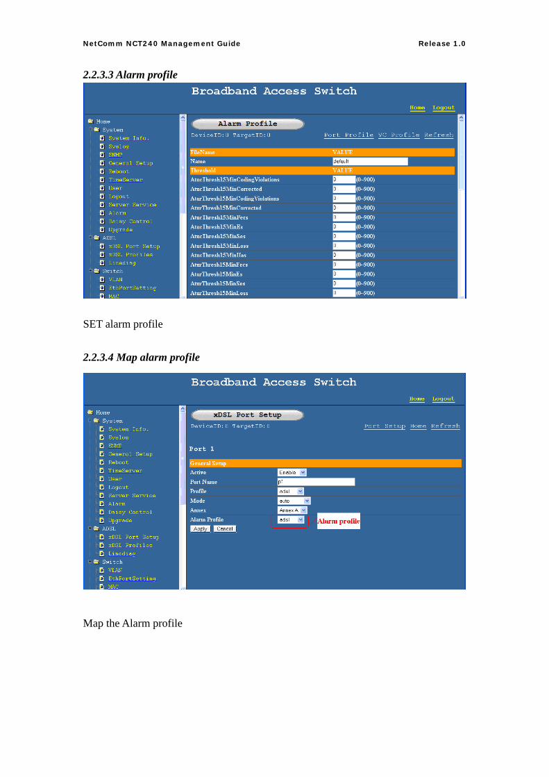
2.2.3.3 Alarm profile
SET alarm profile 2.2.3.4 Map alarm profile
Map the Alarm profile
20
NetComm NCT240 Management Guide Release 1.0
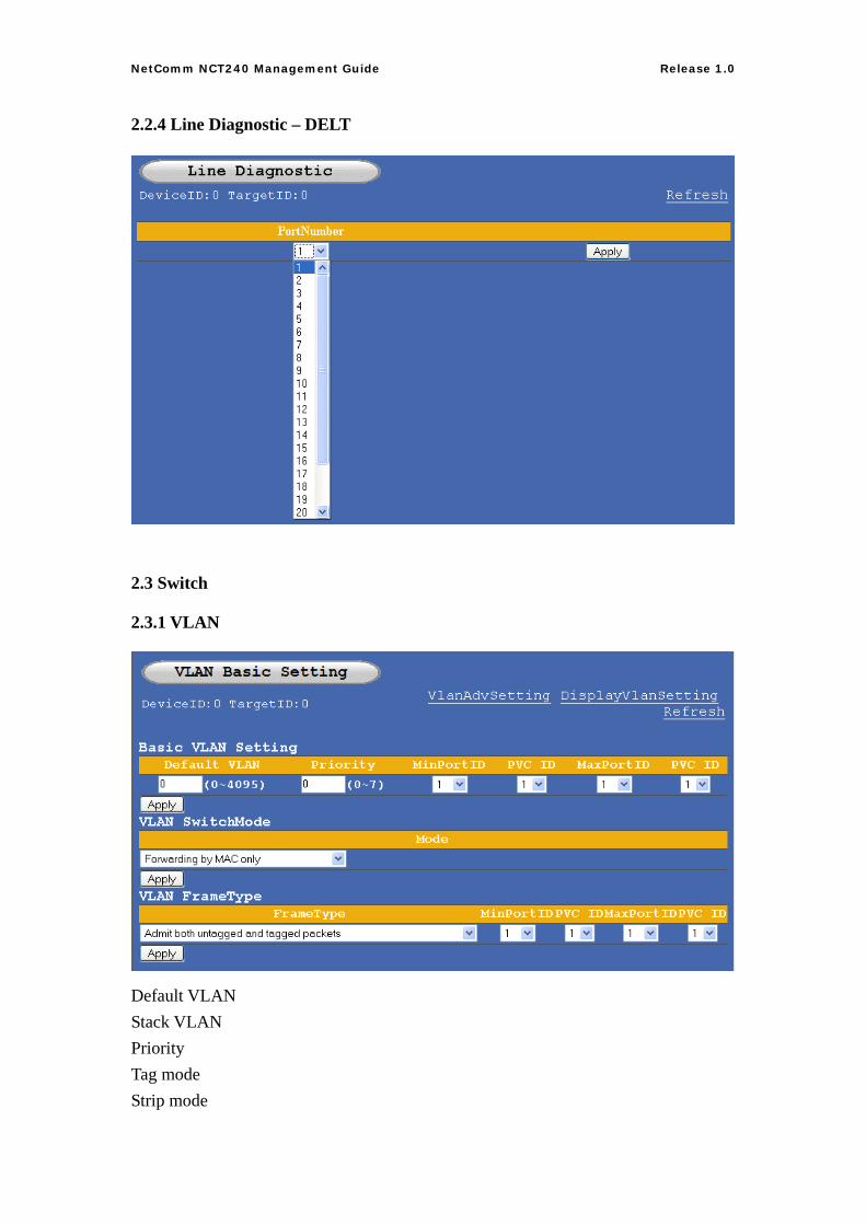
2.2.4 Line Diagnostic – DELT
2.3 Switch
2.3.1 VLAN
Default VLAN Stack VLAN Priority Tag mode Strip mode
21
NetComm NCT240 Management Guide Release 1.0
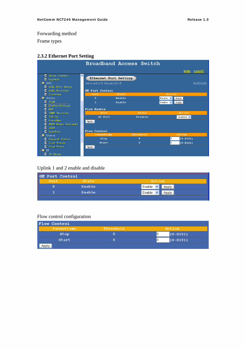
Forwarding method Frame types 2.3.2 Ethernet Port Setting
Uplink 1 and 2 enable and disable
Flow control configuration
22
NetComm NCT240 Management Guide Release 1.0
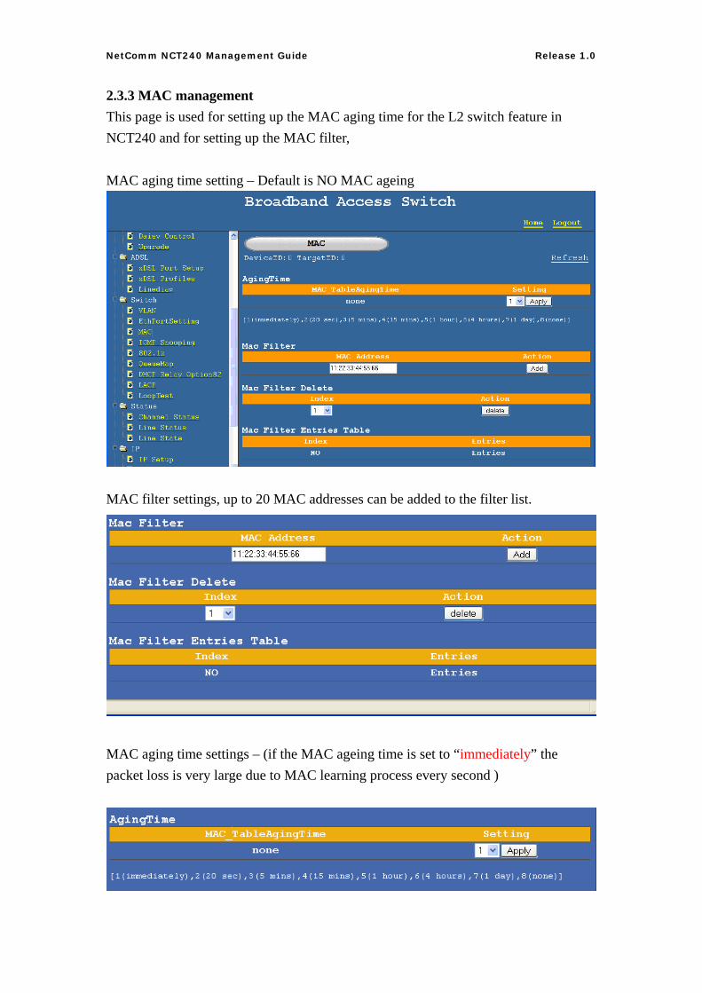
2.3.3 MAC management This page is used for setting up the MAC aging time for the L2 switch feature in NCT240 and for setting up the MAC filter, MAC aging time setting – Default is NO MAC ageing
MAC filter settings, up to 20 MAC addresses can be added to the filter list.
MAC aging time settings – (if the MAC ageing time is set to “immediately” the packet loss is very large due to MAC learning process every second )
23
NetComm NCT240 Management Guide Release 1.0
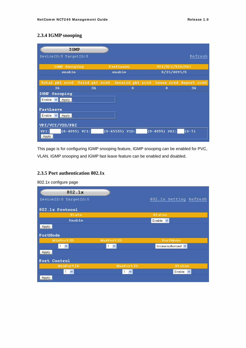
2.3.4 IGMP snooping
This page is for configuring IGMP snooping feature, IGMP snooping can be enabled for PVC,
VLAN. IGMP snooping and IGMP fast leave feature can be enabled and disabled.
2.3.5 Port authentication 802.1x
802.1x configure page
24
NetComm NCT240 Management Guide Release 1.0
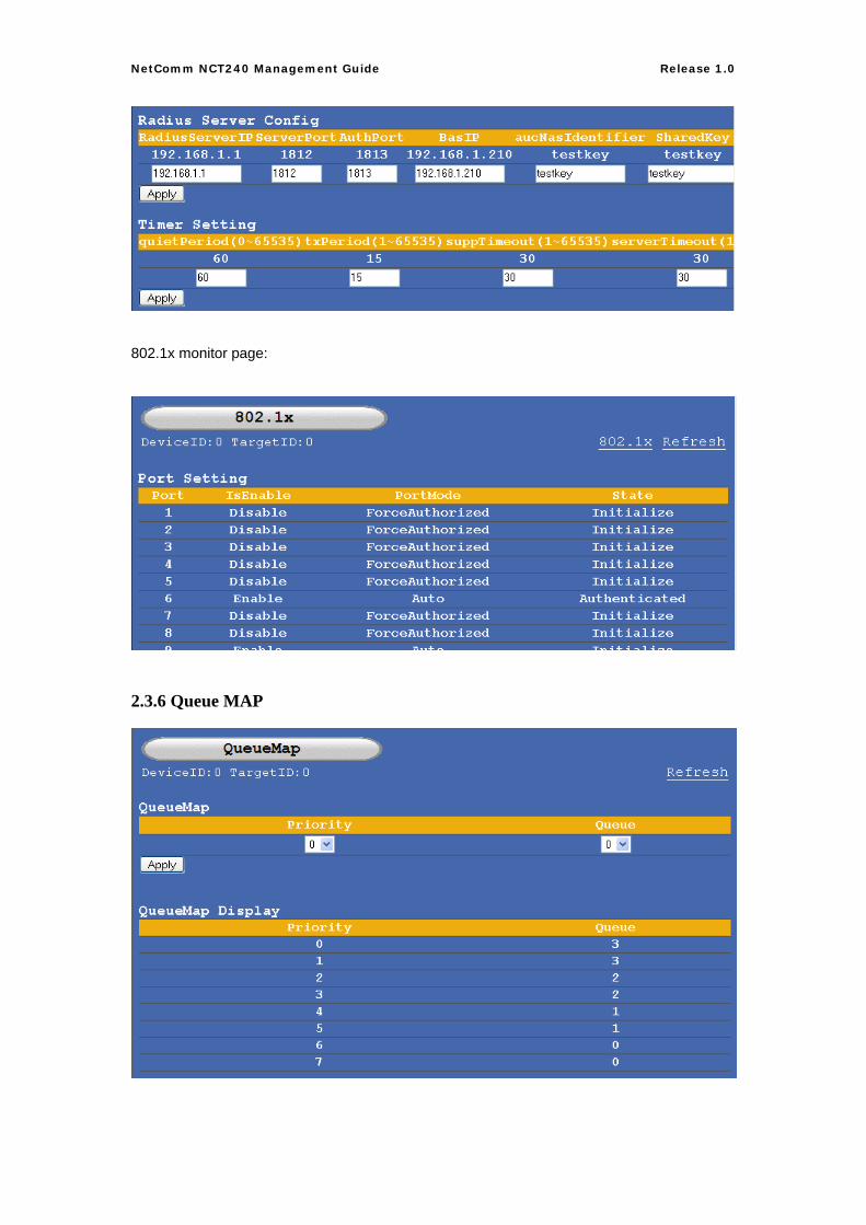
802.1x monitor page:
2.3.6 Queue MAP
25
NetComm NCT240 Management Guide Release 1.0
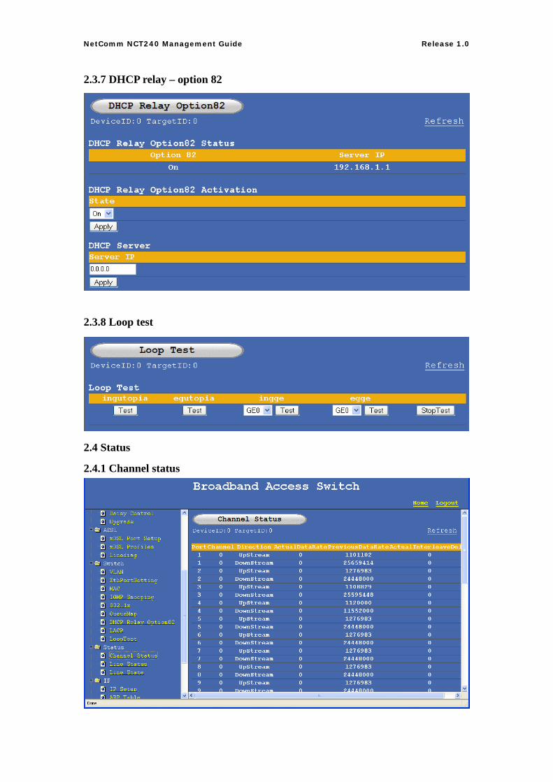
2.3.7 DHCP relay – option 82
2.3.8 Loop test
2.4 Status
2.4.1 Channel status
26
NetComm NCT240 Management Guide Release 1.0
Display the channel status of each port Upstream and Downstream.
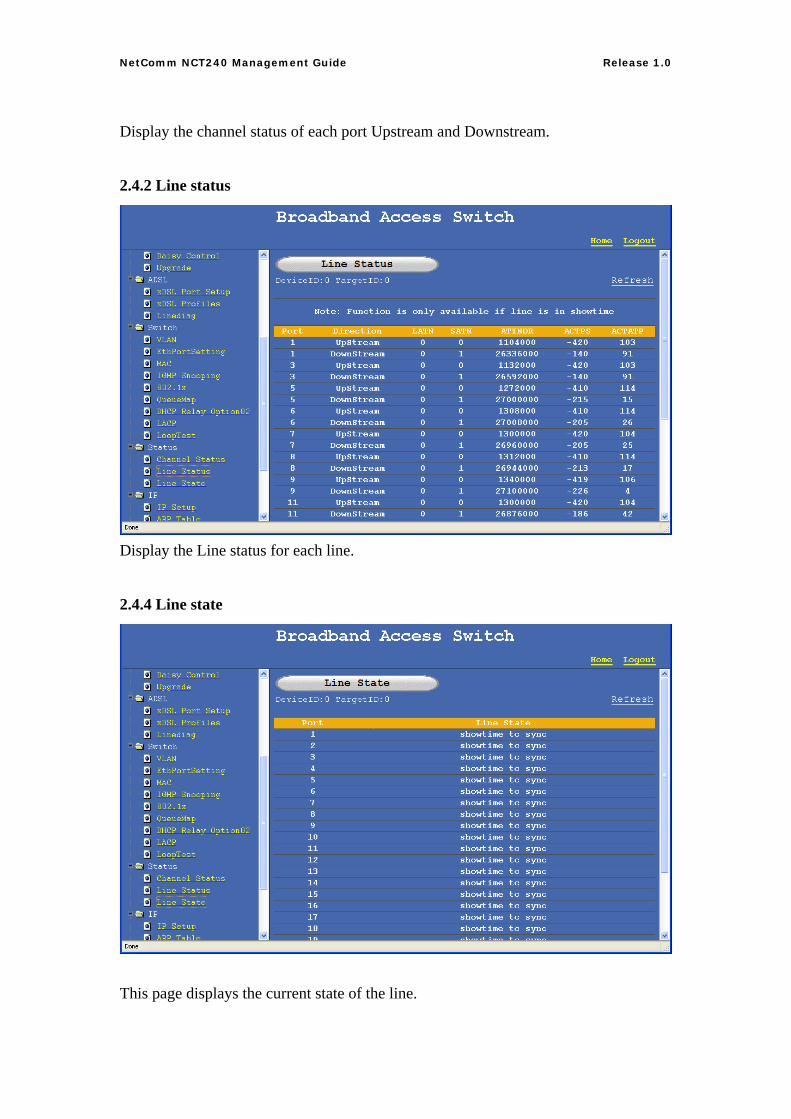
2.4.2 Line status
Display the Line status for each line.
2.4.4 Line state
This page displays the current state of the line.
27
NetComm NCT240 Management Guide Release 1.0
2.5 IP
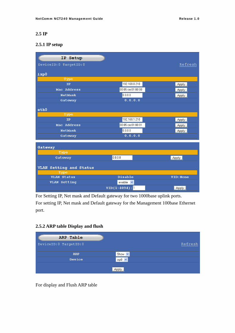
2.5.1 IP setup
For Setting IP, Net mask and Default gateway for two 1000base uplink ports. For setting IP, Net mask and Default gateway for the Management 100base Ethernet port.
2.5.2 ARP table Display and flush
For display and Flush ARP table
28
NetComm NCT240 Management Guide Release 1.0
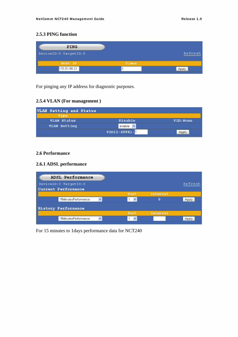
2.5.3 PING function
For pinging any IP address for diagnostic purposes. 2.5.4 VLAN (For management )
2.6 Performance
2.6.1 ADSL performance
For 15 minutes to 1days performance data for NCT240
29
NetComm NCT240 Management Guide Release 1.0
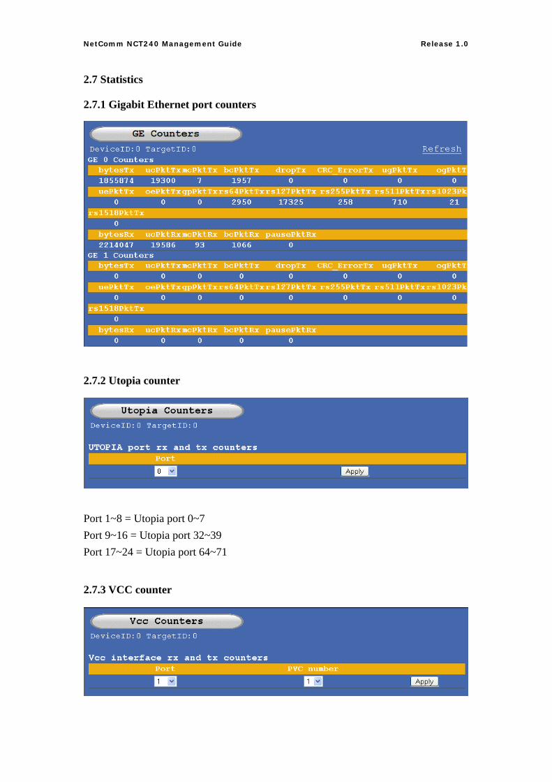
2.7 Statistics
2.7.1 Gigabit Ethernet port counters
2.7.2 Utopia counter
Port 1~8 = Utopia port 0~7 Port 9~16 = Utopia port 32~39 Port 17~24 = Utopia port 64~71
2.7.3 VCC counter
30
NetComm NCT240 Management Guide Release 1.0
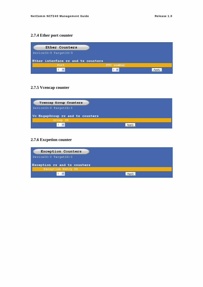
2.7.4 Ether port counter
2.7.5 Vcencap counter
2.7.6 Excpetion counter
31
NetComm NCT240 Management Guide Release 1.0
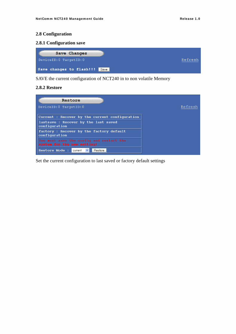
2.8 Configuration
2.8.1 Configuration save
SAVE the current configuration of NCT240 in to non volatile Memory
2.8.2 Restore
Set the current configuration to last saved or factory default settings
32
NetComm NCT240 Management Guide Release 1.0
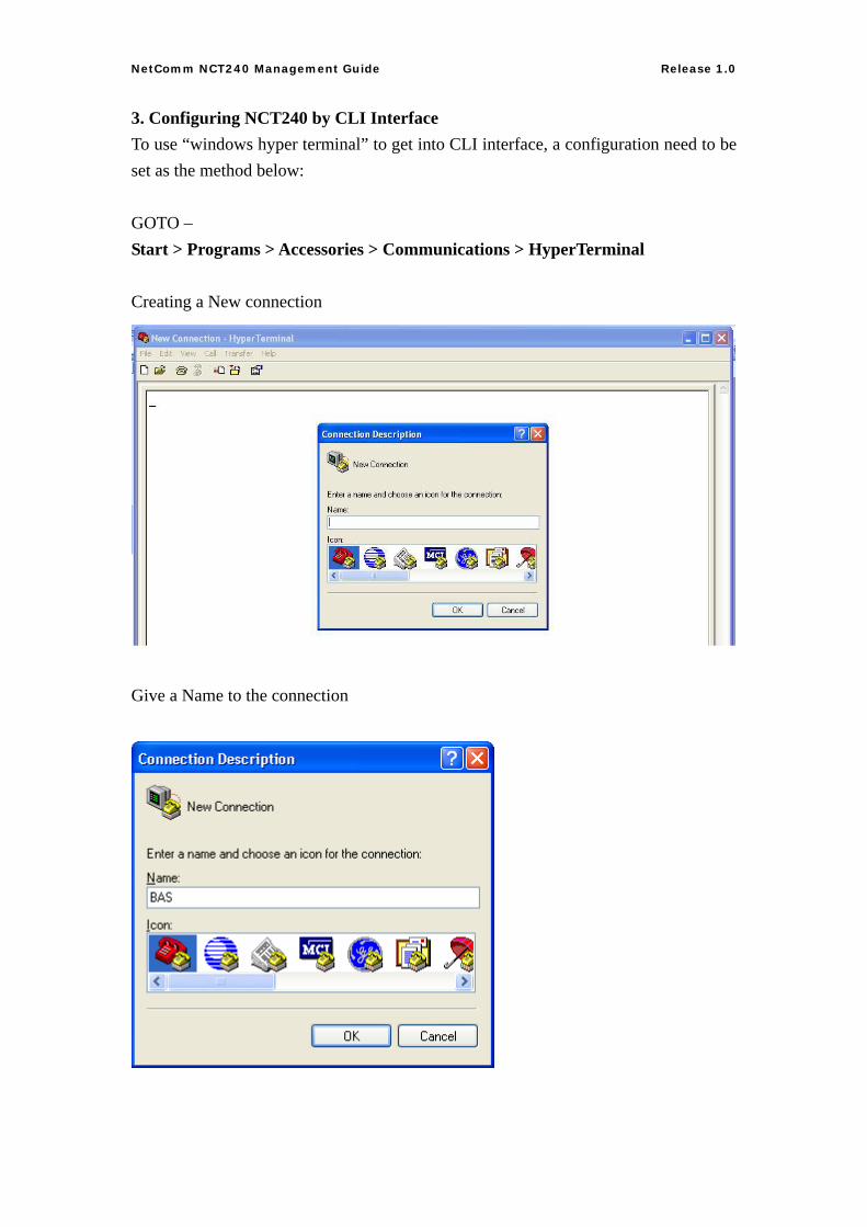
3. Configuring NCT240 by CLI Interface To use “windows hyper terminal” to get into CLI interface, a configuration need to be set as the method below: GOTO – Start > Programs > Accessories > Communications > HyperTerminal Creating a New connection
Give a Name to the connection
33
NetComm NCT240 Management Guide Release 1.0
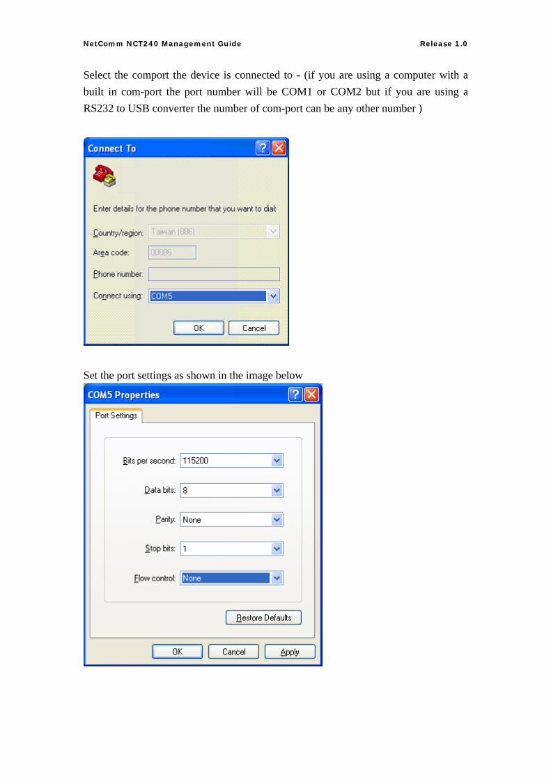
Select the comport the device is connected to - (if you are using a computer with a built in com-port the port number will be COM1 or COM2 but if you are using a RS232 to USB converter the number of com-port can be any other number )
Set the port settings as shown in the image below
34
NetComm NCT240 Management Guide Release 1.0
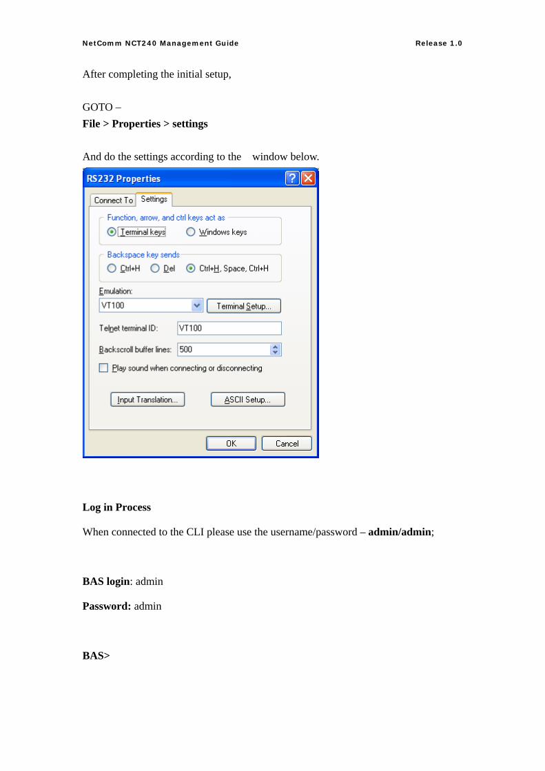
After completing the initial setup, GOTO – File > Properties > settings And do the settings according to the window below.
Log in Process
When connected to the CLI please use the username/password – admin/admin;
BAS login: admin
Password: admin
BAS>
35
NetComm NCT240 Management Guide Release 1.0
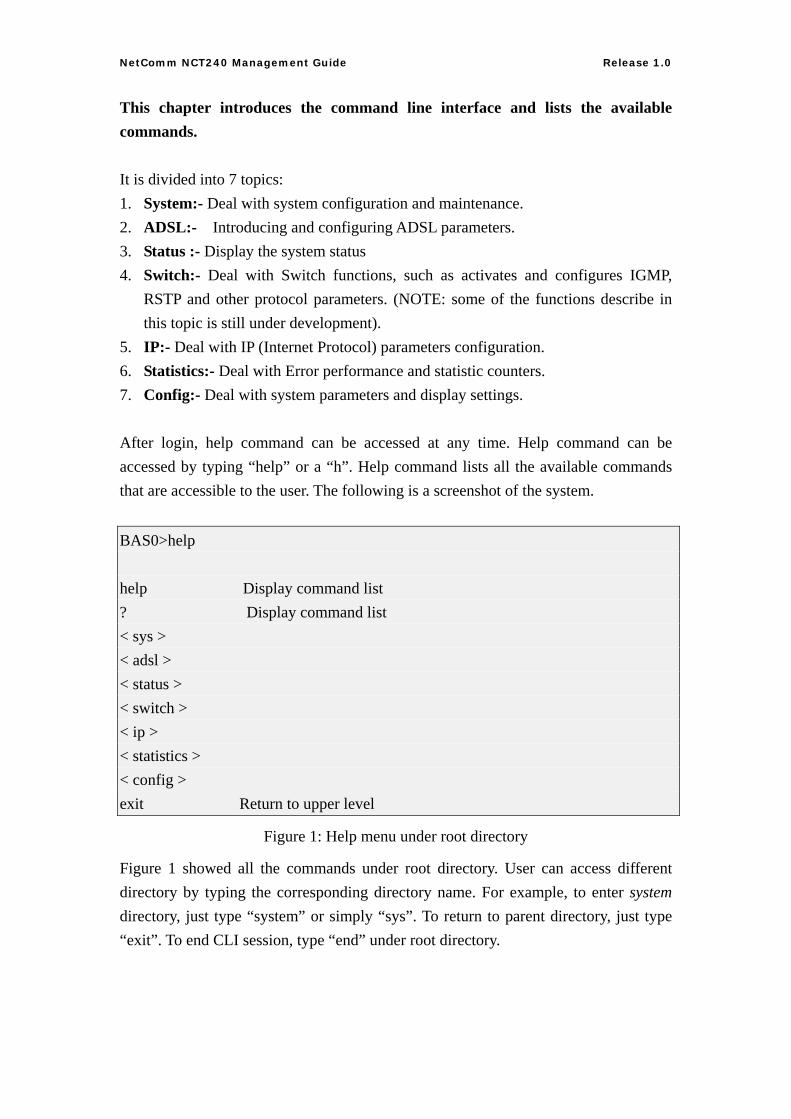
This chapter introduces the command line interface and lists the available commands. It is divided into 7 topics: 1. System:- Deal with system configuration and maintenance. 2. ADSL:- Introducing and configuring ADSL parameters. 3. Status :- Display the system status 4. Switch:- Deal with Switch functions, such as activates and configures IGMP,
RSTP and other protocol parameters. (NOTE: some of the functions describe in this topic is still under development).
5. IP:- Deal with IP (Internet Protocol) parameters configuration. 6. Statistics:- Deal with Error performance and statistic counters. 7. Config:- Deal with system parameters and display settings. After login, help command can be accessed at any time. Help command can be accessed by typing “help” or a “h”. Help command lists all the available commands that are accessible to the user. The following is a screenshot of the system. BAS0>help help Display command list ? Display command list < sys > < adsl > < status > < switch > < ip > < statistics > < config > exit Return to upper level
Figure 1: Help menu under root directory
Figure 1 showed all the commands under root directory. User can access different directory by typing the corresponding directory name. For example, to enter system directory, just type “system” or simply “sys”. To return to parent directory, just type “exit”. To end CLI session, type “end” under root directory.
36
NetComm NCT240 Management Guide Release 1.0
Command format
Some commands required parameter(s). The number of parameter required is different for each command. To know each command’s parameters, just type the command name. For example, to know the command format for XXX, you can type XXX; the screen will show something like this: XXX <aaa|bbb|ccc|ddd> <eee|fff> [ggg] Each set of “<>” bracket represent a parameter and the possible options are enclosed within the bracket, separated by “|”. The option enclosed in the square bracket “[ ]” means this parameter is optional. In this example, we can see that command XXX has three parameters. There are 4 possible options for 1st parameter, namely aaa, bbb, ccc and ddd, and two possible option for 2nd parameter, namely eee and fff, and an optional 3rd parameter. For the command to be executed, you can either type: XXX aaa eee ggg or XXX aaa eee Both of them are valid input, since this command takes two OR three parameters.
37
NetComm NCT240 Management Guide Release 1.0
SYSTEM:
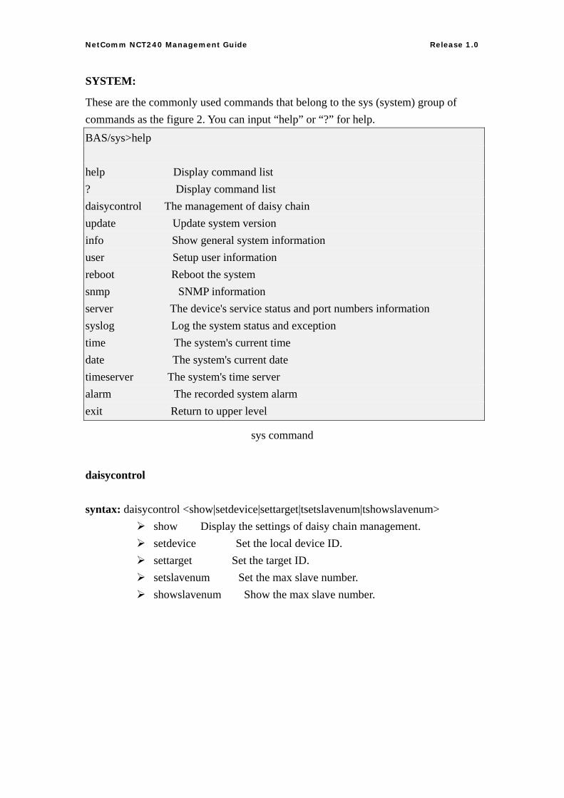
These are the commonly used commands that belong to the sys (system) group of commands as the figure 2. You can input “help” or “?” for help. BAS/sys>help help Display command list ? Display command list daisycontrol The management of daisy chain update Update system version info Show general system information user Setup user information reboot Reboot the system snmp SNMP information server The device's service status and port numbers information syslog Log the system status and exception time The system's current time date The system's current date timeserver The system's time server alarm The recorded system alarm exit Return to upper level
sys command
daisycontrol
syntax: daisycontrol <show|setdevice|settarget|tsetslavenum|tshowslavenum> show Display the settings of daisy chain management. setdevice Set the local device ID. settarget Set the target ID. setslavenum Set the max slave number. showslavenum Show the max slave number.
38
NetComm NCT240 Management Guide Release 1.0
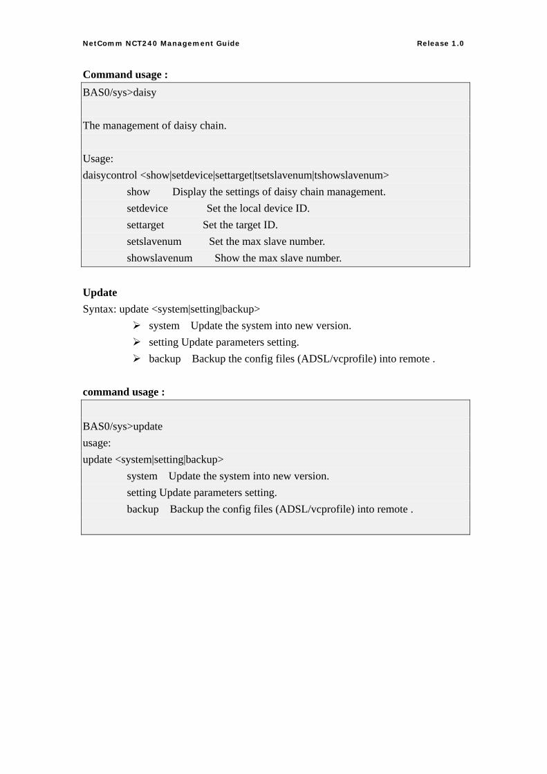
Command usage : BAS0/sys>daisy The management of daisy chain. Usage: daisycontrol <show|setdevice|settarget|tsetslavenum|tshowslavenum> show Display the settings of daisy chain management. setdevice Set the local device ID. settarget Set the target ID. setslavenum Set the max slave number. showslavenum Show the max slave number. Update Syntax: update <system|setting|backup>
system Update the system into new version. setting Update parameters setting. backup Backup the config files (ADSL/vcprofile) into remote .
command usage : BAS0/sys>update usage: update <system|setting|backup> system Update the system into new version. setting Update parameters setting. backup Backup the config files (ADSL/vcprofile) into remote .
39
NetComm NCT240 Management Guide Release 1.0
Info This command shows general system setting about switch name, switch location, contact person and contact phone number. Syntax: info <show | switchname | location | contact | phone>
show – list all the settings of the info menu switchname – switch name location – switch location, you can set this device location into the system contact – contact person that you maybe contact to phone – contact phone number
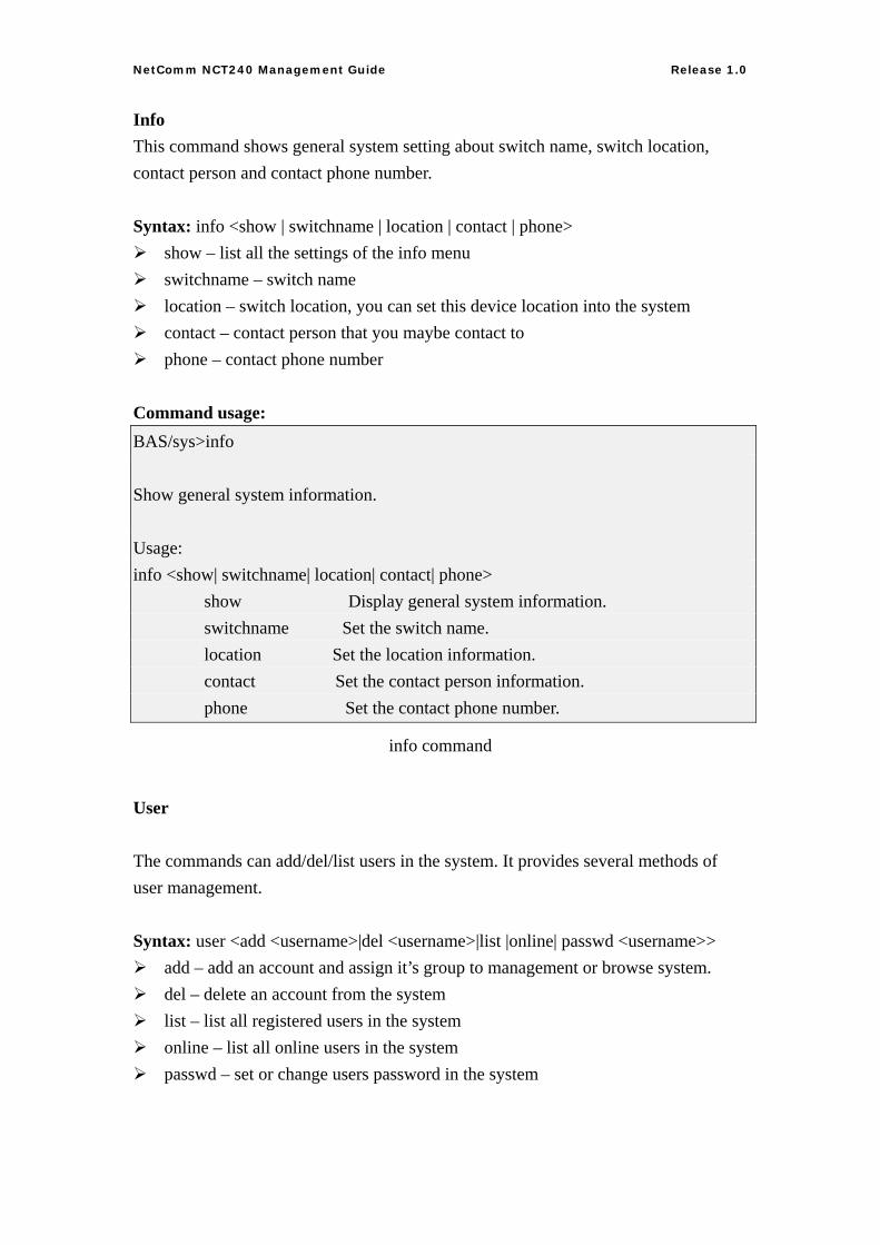
Command usage: BAS/sys>info Show general system information. Usage: info <show| switchname| location| contact| phone> show Display general system information. switchname Set the switch name. location Set the location information. contact Set the contact person information. phone Set the contact phone number.
info command
User
The commands can add/del/list users in the system. It provides several methods of user management. Syntax: user <add <username>|del <username>|list |online| passwd <username>>
add – add an account and assign it’s group to management or browse system. del – delete an account from the system list – list all registered users in the system online – list all online users in the system passwd – set or change users password in the system
40
NetComm NCT240 Management Guide Release 1.0
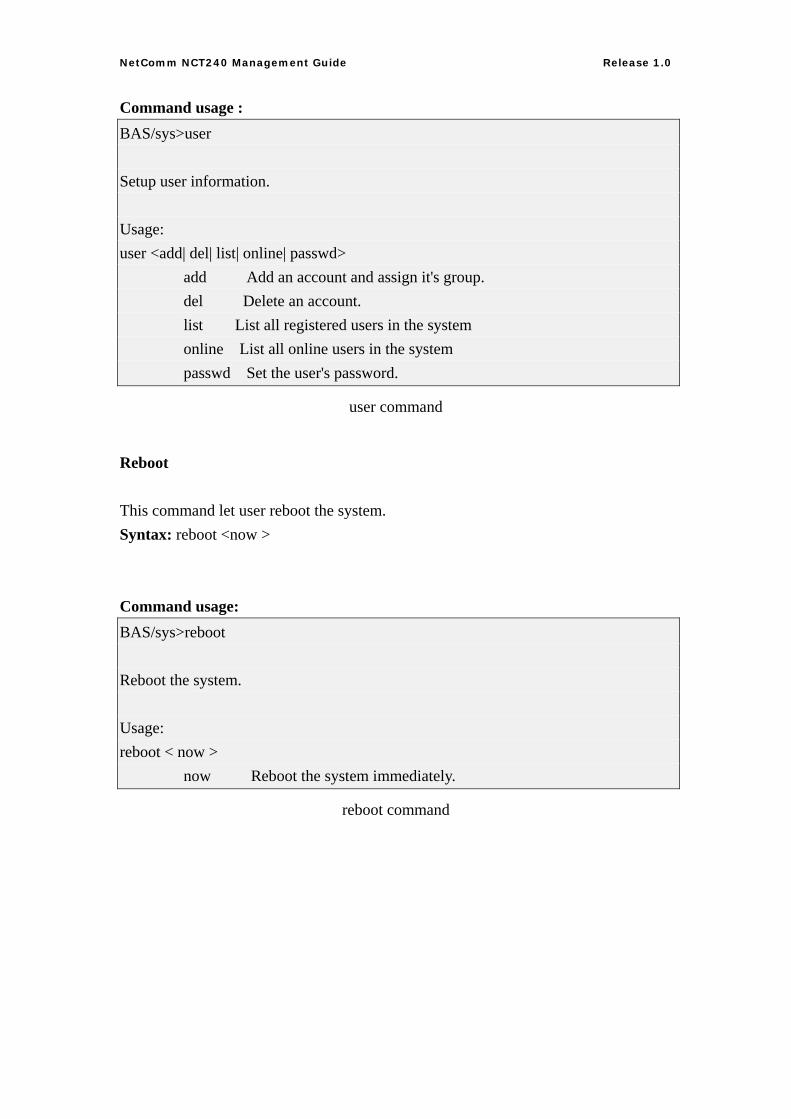
Command usage : BAS/sys>user Setup user information. Usage: user <add| del| list| online| passwd> add Add an account and assign it's group. del Delete an account. list List all registered users in the system online List all online users in the system passwd Set the user's password.
user command
Reboot
This command let user reboot the system. Syntax: reboot <now > Command usage: BAS/sys>reboot Reboot the system. Usage: reboot < now > now Reboot the system immediately.
reboot command
41
NetComm NCT240 Management Guide Release 1.0
SNMP
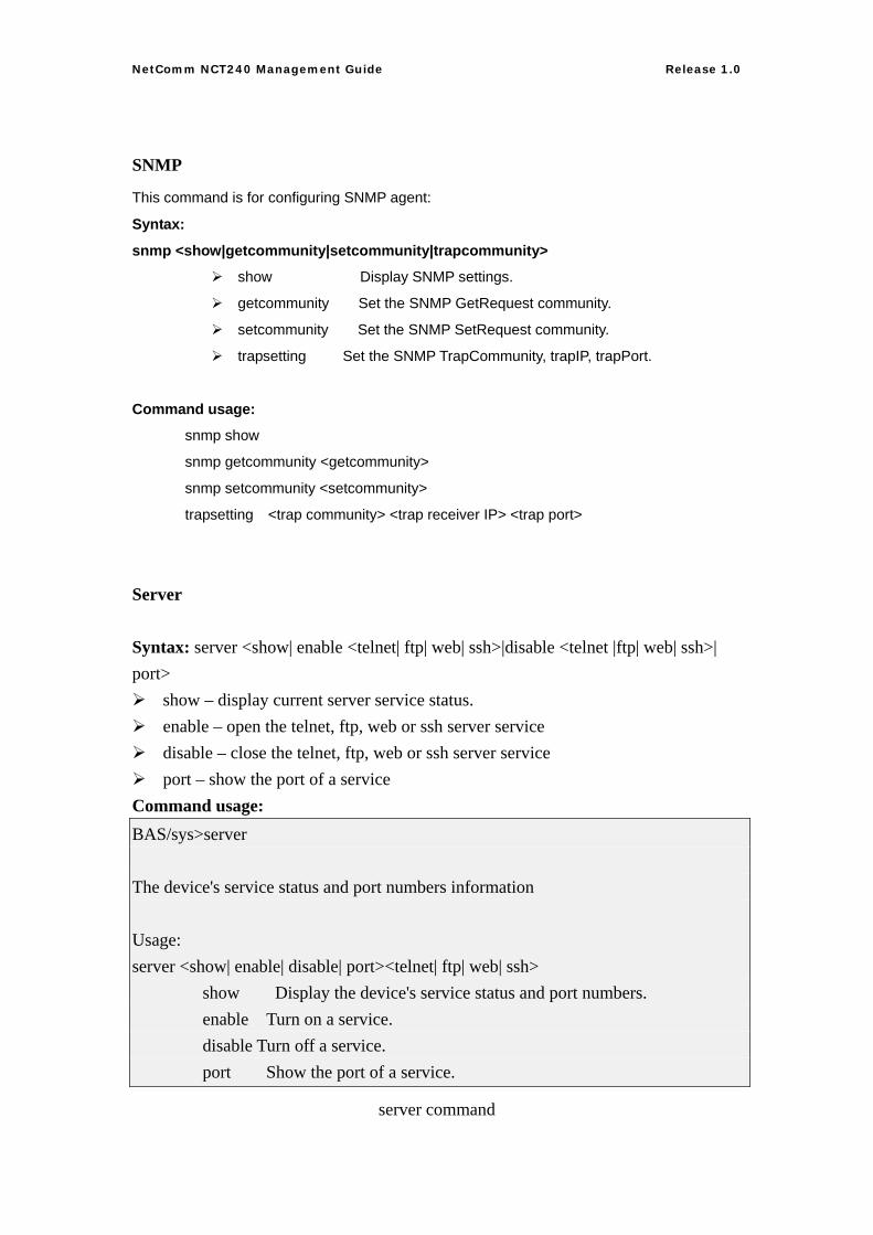
This command is for configuring SNMP agent:
Syntax:
snmp <show|getcommunity|setcommunity|trapcommunity>
show Display SNMP settings.
getcommunity Set the SNMP GetRequest community.
setcommunity Set the SNMP SetRequest community.
trapsetting Set the SNMP TrapCommunity, trapIP, trapPort.
Command usage:
snmp show
snmp getcommunity <getcommunity>
snmp setcommunity <setcommunity>
trapsetting <trap community> <trap receiver IP> <trap port>
Server
Syntax: server <show| enable <telnet| ftp| web| ssh>|disable <telnet |ftp| web| ssh>| port>
show – display current server service status. enable – open the telnet, ftp, web or ssh server service disable – close the telnet, ftp, web or ssh server service port – show the port of a service
Command usage: BAS/sys>server The device's service status and port numbers information Usage: server <show| enable| disable| port><telnet| ftp| web| ssh> show Display the device's service status and port numbers. enable Turn on a service. disable Turn off a service. port Show the port of a service.
server command
42
NetComm NCT240 Management Guide Release 1.0
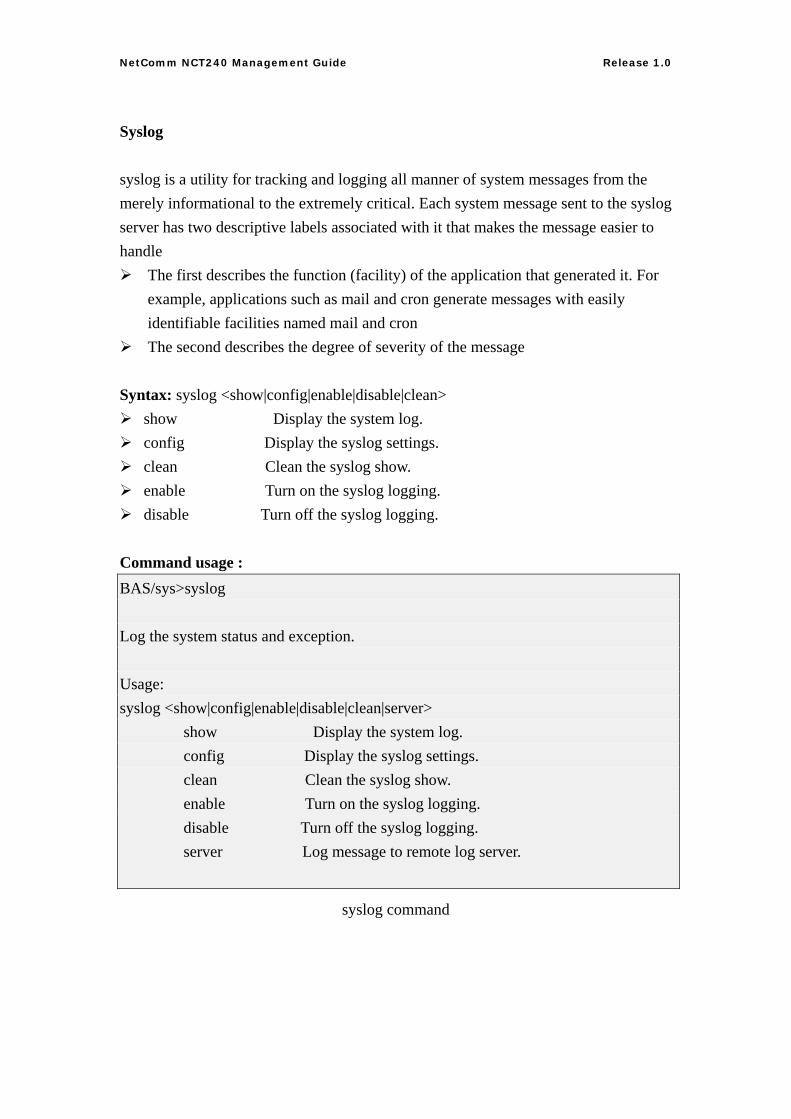
Syslog
syslog is a utility for tracking and logging all manner of system messages from the merely informational to the extremely critical. Each system message sent to the syslog server has two descriptive labels associated with it that makes the message easier to handle
The first describes the function (facility) of the application that generated it. For example, applications such as mail and cron generate messages with easily identifiable facilities named mail and cron
The second describes the degree of severity of the message Syntax: syslog <show|config|enable|disable|clean>
show Display the system log. config Display the syslog settings. clean Clean the syslog show. enable Turn on the syslog logging. disable Turn off the syslog logging.
Command usage : BAS/sys>syslog Log the system status and exception. Usage: syslog <show|config|enable|disable|clean|server> show Display the system log. config Display the syslog settings. clean Clean the syslog show. enable Turn on the syslog logging. disable Turn off the syslog logging. server Log message to remote log server.
syslog command
43
NetComm NCT240 Management Guide Release 1.0
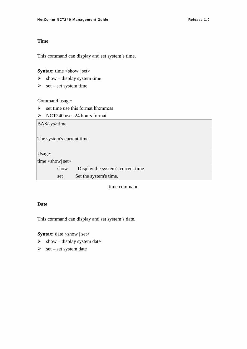
Time
This command can display and set system’s time. Syntax: time <show | set>
show – display system time set – set system time
Command usage:
set time use this format hh:mm:ss NCT240 uses 24 hours format
BAS/sys>time The system's current time Usage: time <show| set> show Display the system's current time. set Set the system's time.
time command
Date
This command can display and set system’s date. Syntax: date <show | set>
show – display system date set – set system date
44
NetComm NCT240 Management Guide Release 1.0
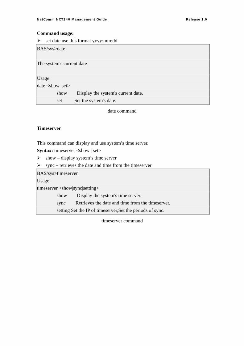
Command usage: set date use this format yyyy:mm:dd
BAS/sys>date The system's current date Usage: date <show| set> show Display the system's current date. set Set the system's date.
date command
Timeserver
This command can display and use system’s time server. Syntax: timeserver <show | set>
show – display system’s time server sync – retrieves the date and time from the timeserver
BAS/sys>timeserver Usage: timeserver <show|sync|setting> show Display the system's time server. sync Retrieves the date and time from the timeserver. setting Set the IP of timeserver,Set the periods of sync.
timeserver command
45
NetComm NCT240 Management Guide Release 1.0
Alarm
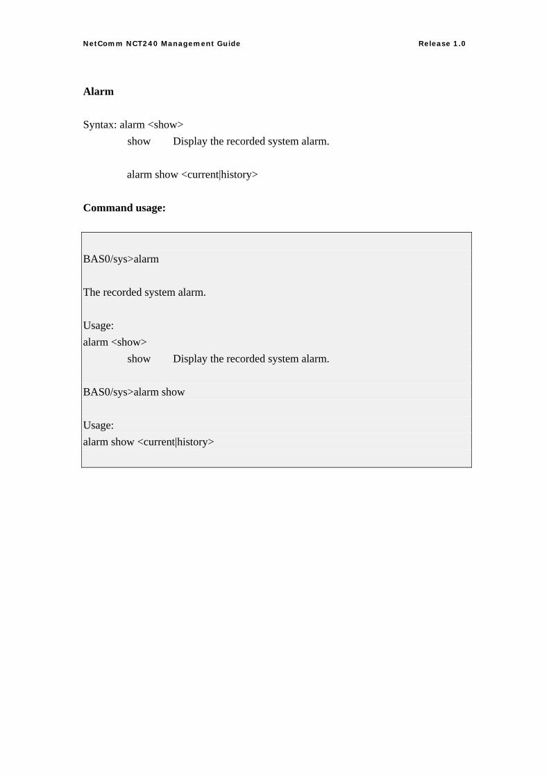
Syntax: alarm <show> show Display the recorded system alarm.
alarm show <current|history>
Command usage: BAS0/sys>alarm The recorded system alarm. Usage: alarm <show> show Display the recorded system alarm. BAS0/sys>alarm show Usage: alarm show <current|history>
46
NetComm NCT240 Management Guide Release 1.0
ADSL:
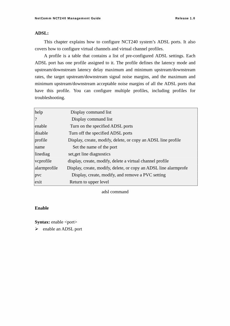
This chapter explains how to configure NCT240 system’s ADSL ports. It also covers how to configure virtual channels and virtual channel profiles. A profile is a table that contains a list of pre-configured ADSL settings. Each ADSL port has one profile assigned to it. The profile defines the latency mode and upstream/downstream latency delay maximum and minimum upstream/downstream rates, the target upstream/downstream signal noise margins, and the maximum and minimum upstream/downstream acceptable noise margins of all the ADSL ports that have this profile. You can configure multiple profiles, including profiles for troubleshooting. help Display command list ? Display command list enable Turn on the specified ADSL ports disable Turn off the specified ADSL ports profile Display, create, modify, delete, or copy an ADSL line profile name Set the name of the port linediag set,get line diagnostics vcprofile display, create, modify, delete a virtual channel profile alarmprofile Display, create, modify, delete, or copy an ADSL line alarmprofe pvc Display, create, modify, and remove a PVC setting exit Return to upper level
adsl command
Enable
Syntax: enable <port> enable an ADSL port
47
NetComm NCT240 Management Guide Release 1.0
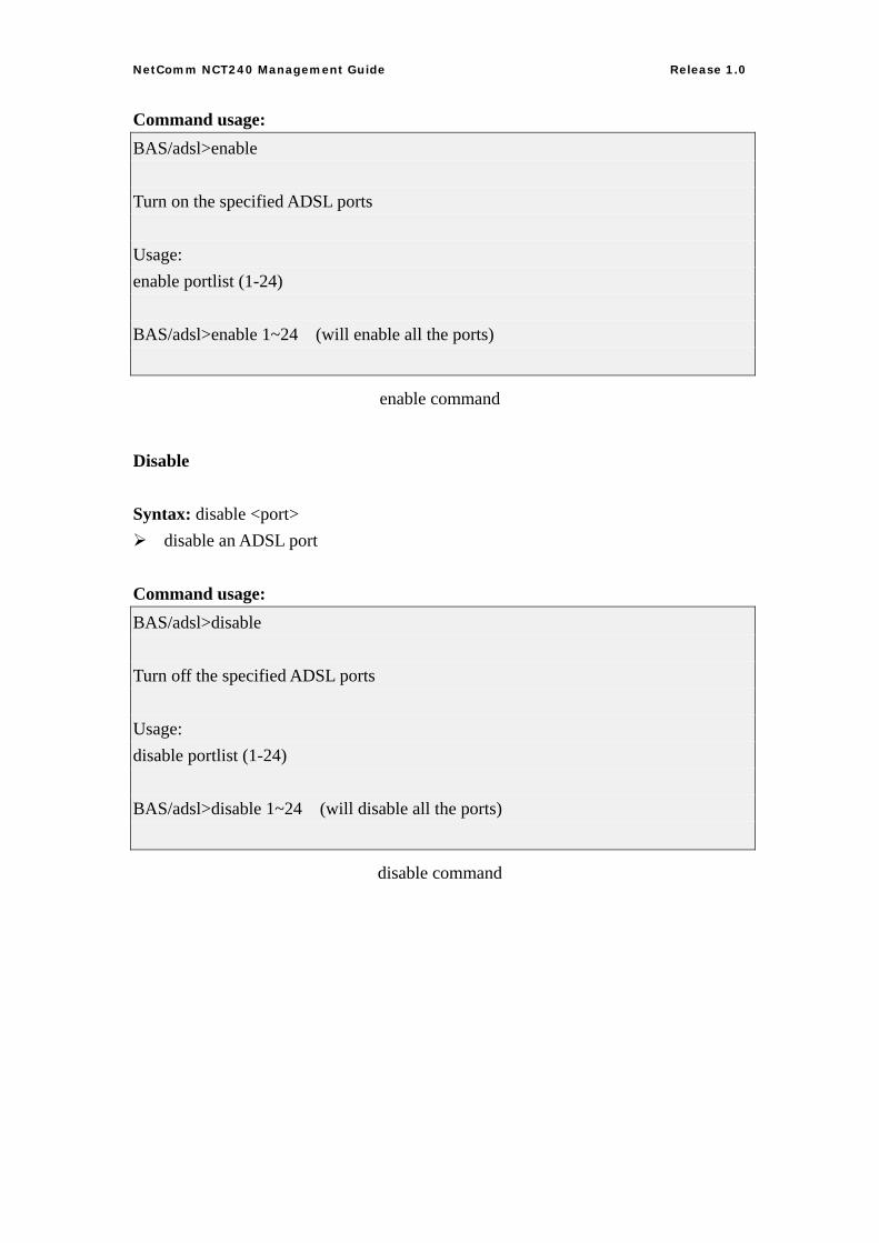
Command usage: BAS/adsl>enable Turn on the specified ADSL ports Usage: enable portlist (1-24) BAS/adsl>enable 1~24 (will enable all the ports)
enable command
Disable
Syntax: disable <port> disable an ADSL port
Command usage: BAS/adsl>disable Turn off the specified ADSL ports Usage: disable portlist (1-24) BAS/adsl>disable 1~24 (will disable all the ports)
disable command
48
NetComm NCT240 Management Guide Release 1.0
Profile
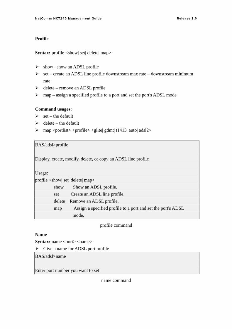
Syntax: profile <show| set| delete| map>
show –show an ADSL profile set – create an ADSL line profile downstream max rate – downstream minimum
rate delete – remove an ADSL profile map – assign a specified profile to a port and set the port's ADSL mode
Command usages:
set – the default delete – the default map <portlist> <profile> <glite| gdmt| t1413| auto| adsl2>
BAS/adsl>profile Display, create, modify, delete, or copy an ADSL line profile Usage: profile <show| set| delete| map> show Show an ADSL profile. set Create an ADSL line profile. delete Remove an ADSL profile. map Assign a specified profile to a port and set the port's ADSL mode.
profile command
Name Syntax: name <port> <name>
Give a name for ADSL port profile BAS/adsl>name Enter port number you want to set
name command
49
NetComm NCT240 Management Guide Release 1.0
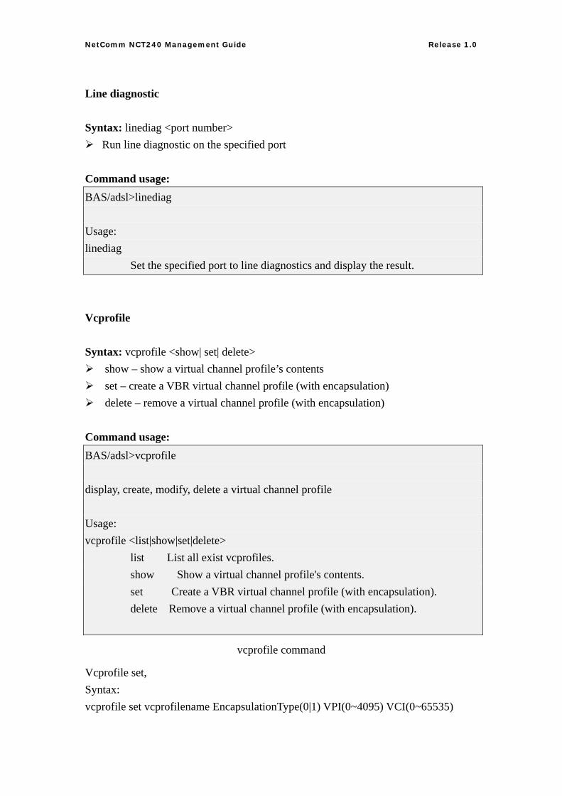
Line diagnostic
Syntax: linediag <port number> Run line diagnostic on the specified port
Command usage: BAS/adsl>linediag Usage: linediag Set the specified port to line diagnostics and display the result.
Vcprofile
Syntax: vcprofile <show| set| delete> show – show a virtual channel profile’s contents set – create a VBR virtual channel profile (with encapsulation) delete – remove a virtual channel profile (with encapsulation)
Command usage: BAS/adsl>vcprofile display, create, modify, delete a virtual channel profile Usage: vcprofile <list|show|set|delete> list List all exist vcprofiles. show Show a virtual channel profile's contents. set Create a VBR virtual channel profile (with encapsulation). delete Remove a virtual channel profile (with encapsulation).
vcprofile command
Vcprofile set, Syntax: vcprofile set vcprofilename EncapsulationType(0|1) VPI(0~4095) VCI(0~65535)
50
NetComm NCT240 Management Guide Release 1.0
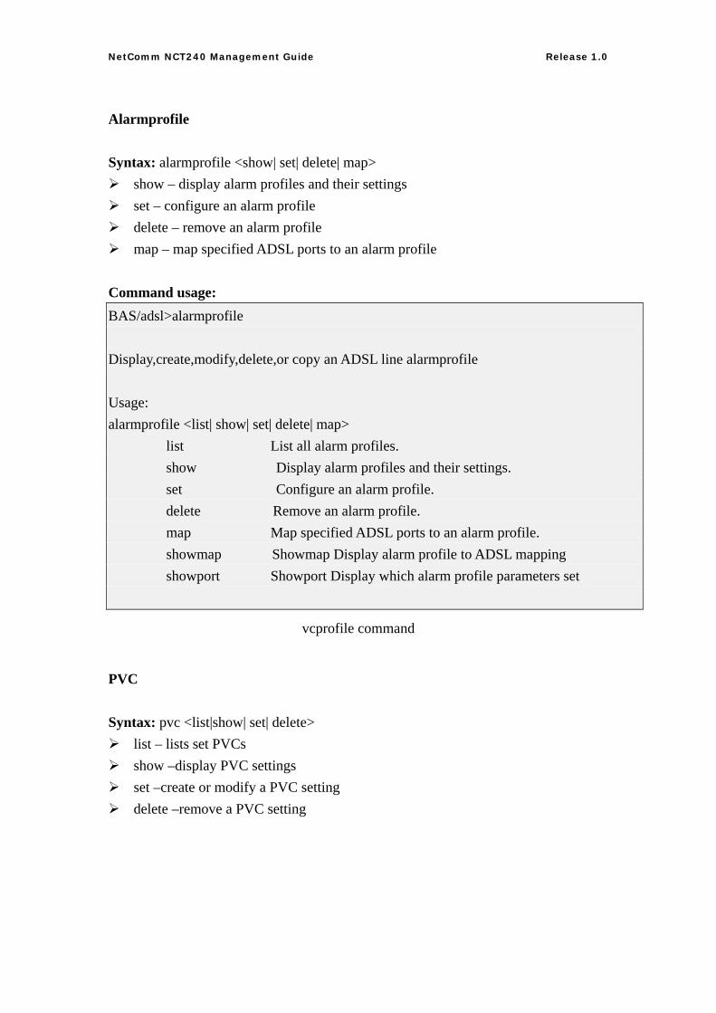
Alarmprofile
Syntax: alarmprofile <show| set| delete| map> show – display alarm profiles and their settings set – configure an alarm profile delete – remove an alarm profile map – map specified ADSL ports to an alarm profile
Command usage: BAS/adsl>alarmprofile Display,create,modify,delete,or copy an ADSL line alarmprofile Usage: alarmprofile <list| show| set| delete| map> list List all alarm profiles. show Display alarm profiles and their settings. set Configure an alarm profile. delete Remove an alarm profile. map Map specified ADSL ports to an alarm profile. showmap Showmap Display alarm profile to ADSL mapping showport Showport Display which alarm profile parameters set
vcprofile command
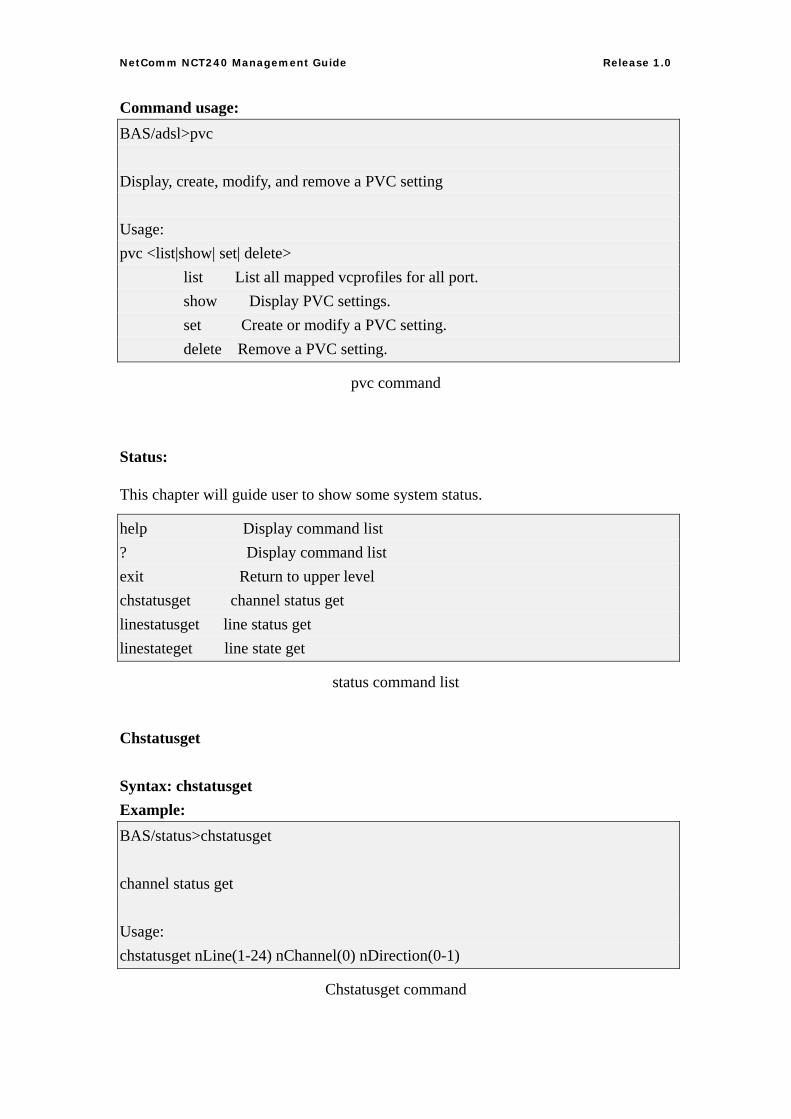
PVC
Syntax: pvc <list|show| set| delete> list – lists set PVCs show –display PVC settings set –create or modify a PVC setting delete –remove a PVC setting
51
NetComm NCT240 Management Guide Release 1.0
Command usage: BAS/adsl>pvc Display, create, modify, and remove a PVC setting Usage: pvc <list|show| set| delete> list List all mapped vcprofiles for all port. show Display PVC settings. set Create or modify a PVC setting. delete Remove a PVC setting.
pvc command
Status:
This chapter will guide user to show some system status.
help Display command list ? Display command list exit Return to upper level chstatusget channel status get linestatusget line status get linestateget line state get
status command list
Chstatusget
Syntax: chstatusget Example: BAS/status>chstatusget channel status get Usage: chstatusget nLine(1-24) nChannel(0) nDirection(0-1)
Chstatusget command
52
NetComm NCT240 Management Guide Release 1.0
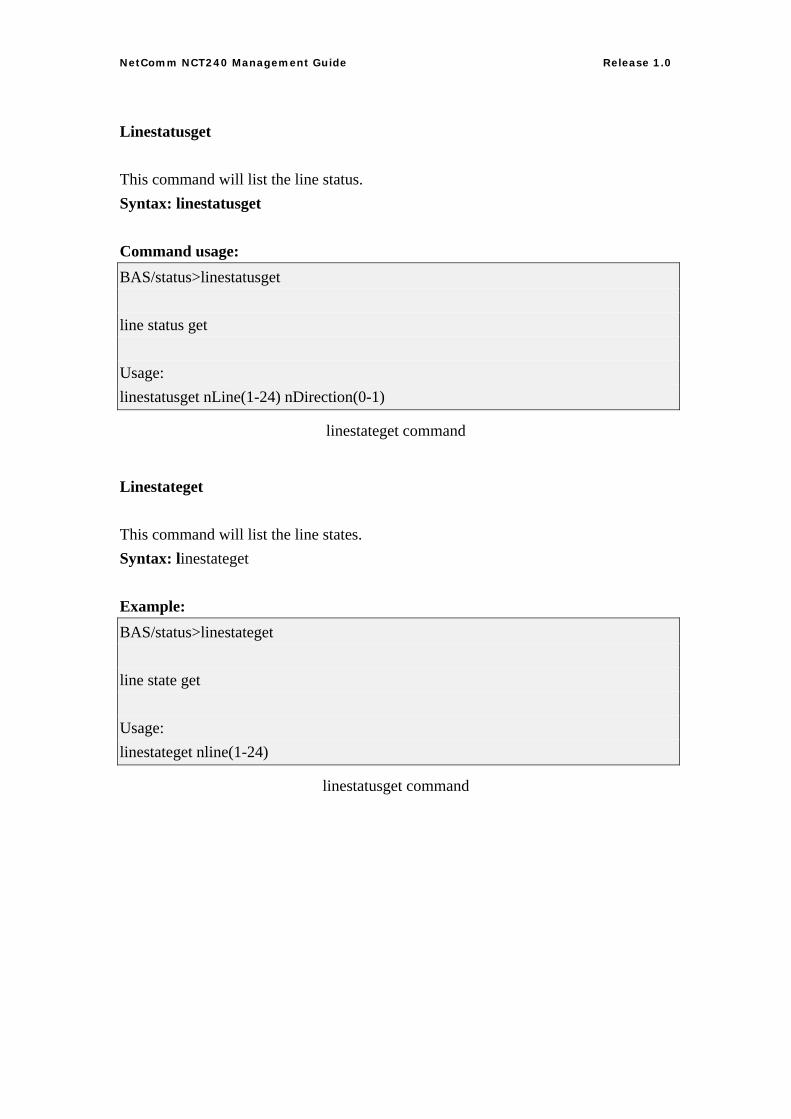
Linestatusget
This command will list the line status. Syntax: linestatusget Command usage: BAS/status>linestatusget line status get Usage: linestatusget nLine(1-24) nDirection(0-1)
linestateget command
Linestateget
This command will list the line states. Syntax: linestateget Example: BAS/status>linestateget line state get Usage: linestateget nline(1-24)
linestatusget command
53
NetComm NCT240 Management Guide Release 1.0
SWITCH:
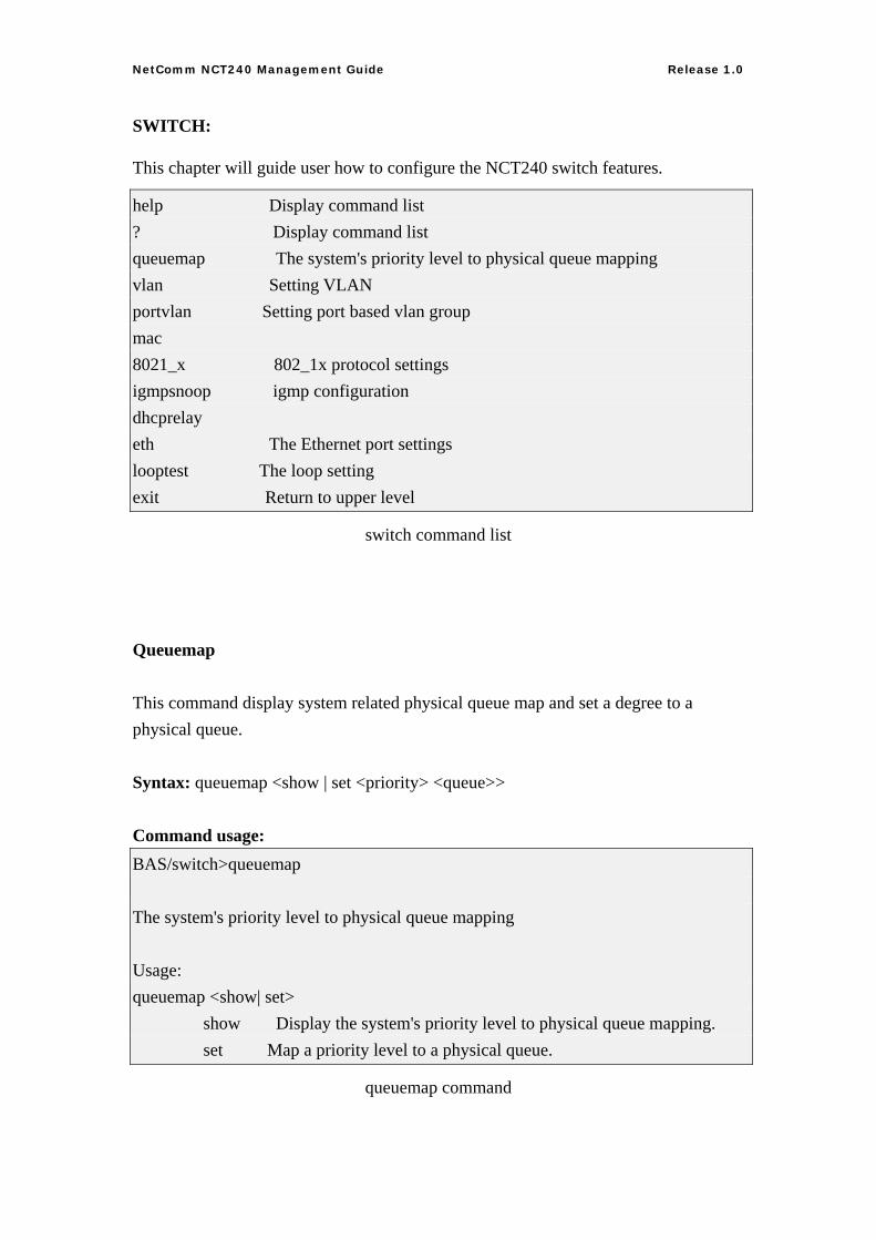
This chapter will guide user how to configure the NCT240 switch features.
help Display command list ? Display command list queuemap The system's priority level to physical queue mapping vlan Setting VLAN portvlan Setting port based vlan group mac 8021_x 802_1x protocol settings igmpsnoop igmp configuration dhcprelay eth The Ethernet port settings looptest The loop setting exit Return to upper level
switch command list
Queuemap
This command display system related physical queue map and set a degree to a physical queue. Syntax: queuemap <show | set <priority> <queue>> Command usage: BAS/switch>queuemap The system's priority level to physical queue mapping Usage: queuemap <show| set> show Display the system's priority level to physical queue mapping. set Map a priority level to a physical queue.
queuemap command
54
NetComm NCT240 Management Guide Release 1.0
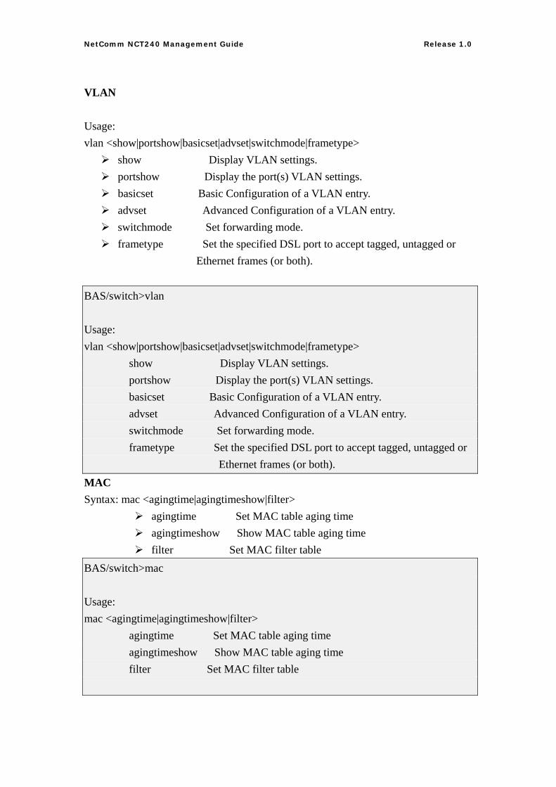
VLAN
Usage: vlan <show|portshow|basicset|advset|switchmode|frametype>
show Display VLAN settings. portshow Display the port(s) VLAN settings. basicset Basic Configuration of a VLAN entry. advset Advanced Configuration of a VLAN entry. switchmode Set forwarding mode. frametype Set the specified DSL port to accept tagged, untagged or
Ethernet frames (or both).
BAS/switch>vlan Usage: vlan <show|portshow|basicset|advset|switchmode|frametype> show Display VLAN settings. portshow Display the port(s) VLAN settings. basicset Basic Configuration of a VLAN entry. advset Advanced Configuration of a VLAN entry. switchmode Set forwarding mode. frametype Set the specified DSL port to accept tagged, untagged or Ethernet frames (or both). MAC Syntax: mac <agingtime|agingtimeshow|filter>
agingtime Set MAC table aging time agingtimeshow Show MAC table aging time filter Set MAC filter table
BAS/switch>mac Usage: mac <agingtime|agingtimeshow|filter> agingtime Set MAC table aging time agingtimeshow Show MAC table aging time filter Set MAC filter table
55
NetComm NCT240 Management Guide Release 1.0
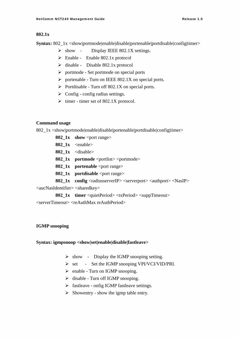
802.1x
Syntax: 802_1x <show|portmode|enable|disable|portenable|portdisable|config|timer> show - Display IEEE 802.1X settings. Enable - Enable 802.1x protocol disable - Disable 802.1x protocol portmode - Set portmode on special ports portenable - Turn on IEEE 802.1X on special ports. Portdisable - Turn off 802.1X on special ports. Config - config radius settings. timer - timer set of 802.1X protocol.
Command usage 802_1x <show|portmode|enable|disable|portenable|portdisable|config|timer> 802_1x show <port range> 802_1x <enable> 802_1x <disable> 802_1x portmode <portlist> <portmode> 802_1x portenable <port range> 802_1x portdisable <port range> 802_1x config <radiusserverIP> <serverport> <authport> <NasIP> <aucNasIdentifier> <sharedkey> 802_1x timer <quietPeriod> <txPeriod> <suppTimeout> <serverTimeout> <reAuthMax reAuthPeriod>
IGMP snooping
Syntax: igmpsnoop <show|set|enable|disable|fastleave>
show - Display the IGMP snooping setting. set - Set the IGMP snooping VPI/VCI/VID/PRI. enable - Turn on IGMP snooping. disable - Turn off IGMP snooping. fastleave - onfig IGMP fastleave settings. Showentry - show the igmp table entry.
56
NetComm NCT240 Management Guide Release 1.0
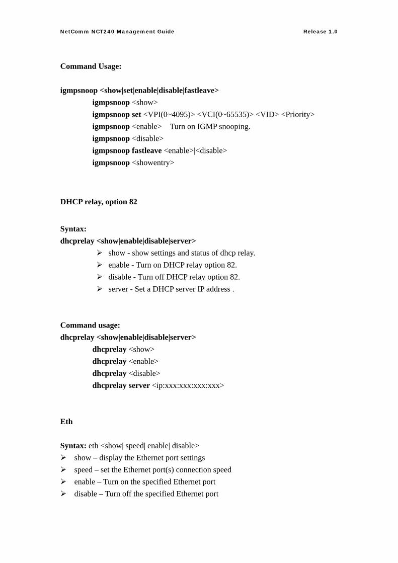
Command Usage: igmpsnoop <show|set|enable|disable|fastleave> igmpsnoop <show> igmpsnoop set <VPI(0~4095)> <VCI(0~65535)> <VID> <Priority> igmpsnoop <enable> Turn on IGMP snooping. igmpsnoop <disable> igmpsnoop fastleave <enable>|<disable> igmpsnoop <showentry>
DHCP relay, option 82
Syntax: dhcprelay <show|enable|disable|server>
show - show settings and status of dhcp relay. enable - Turn on DHCP relay option 82. disable - Turn off DHCP relay option 82. server - Set a DHCP server IP address .
Command usage: dhcprelay <show|enable|disable|server> dhcprelay <show> dhcprelay <enable> dhcprelay <disable> dhcprelay server <ip:xxx:xxx:xxx:xxx>
Eth
Syntax: eth <show| speed| enable| disable> show – display the Ethernet port settings speed – set the Ethernet port(s) connection speed enable – Turn on the specified Ethernet port disable – Turn off the specified Ethernet port
57
NetComm NCT240 Management Guide Release 1.0
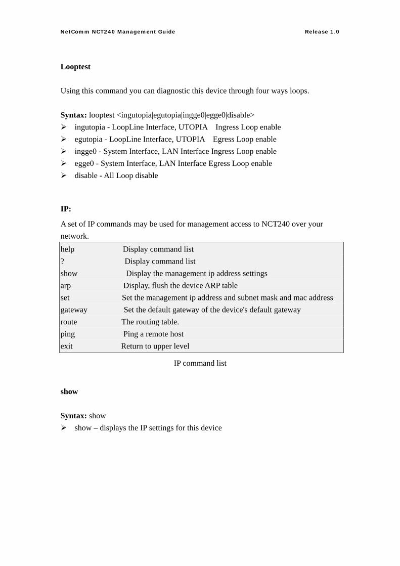
Looptest
Using this command you can diagnostic this device through four ways loops. Syntax: looptest <ingutopia|egutopia|ingge0|egge0|disable>
ingutopia - LoopLine Interface, UTOPIA Ingress Loop enable egutopia - LoopLine Interface, UTOPIA Egress Loop enable ingge0 - System Interface, LAN Interface Ingress Loop enable egge0 - System Interface, LAN Interface Egress Loop enable disable - All Loop disable
IP:
A set of IP commands may be used for management access to NCT240 over your network. help Display command list ? Display command list show Display the management ip address settings arp Display, flush the device ARP table set Set the management ip address and subnet mask and mac address gateway Set the default gateway of the device's default gateway route The routing table. ping Ping a remote host exit Return to upper level
IP command list
show
Syntax: show show – displays the IP settings for this device
58
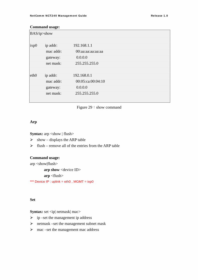
NetComm NCT240 Management Guide Release 1.0
Command usage: BAS/ip>show ixp0 ip addr: 192.168.1.1 mac addr: 00:aa:aa:aa:aa:aa gateway: 0.0.0.0 net mask: 255.255.255.0 eth0 ip addr: 192.168.0.1 mac addr: 00:05:ca:00:04:10 gateway: 0.0.0.0 net mask: 255.255.255.0
Figure 29:show command
Arp
Syntax: arp <show | flush> show – displays the ARP table flush – remove all of the entries from the ARP table
Command usage: arp <show|flush> arp show <device ID> arp <flush> *** Device IP : uplink = eth0 , MGMT = ixp0
Set
Syntax: set <ip| netmask| mac> ip –set the management ip address netmask –set the management subnet mask mac –set the management mac address
59
NetComm NCT240 Management Guide Release 1.0
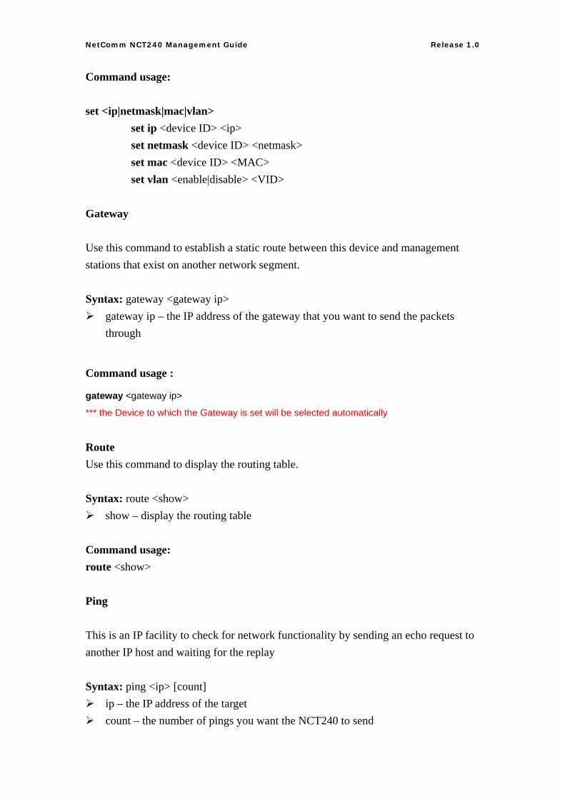
Command usage: set <ip|netmask|mac|vlan> set ip <device ID> <ip> set netmask <device ID> <netmask> set mac <device ID> <MAC> set vlan <enable|disable> <VID>
Gateway
Use this command to establish a static route between this device and management stations that exist on another network segment. Syntax: gateway <gateway ip>
gateway ip – the IP address of the gateway that you want to send the packets through
Command usage :
gateway <gateway ip>
*** the Device to which the Gateway is set will be selected automatically
Route Use this command to display the routing table. Syntax: route <show>
show – display the routing table Command usage: route <show>
Ping
This is an IP facility to check for network functionality by sending an echo request to another IP host and waiting for the replay Syntax: ping <ip> [count]
ip – the IP address of the target count – the number of pings you want the NCT240 to send
60
NetComm NCT240 Management Guide Release 1.0
Command usage :
ping <ip> <count>
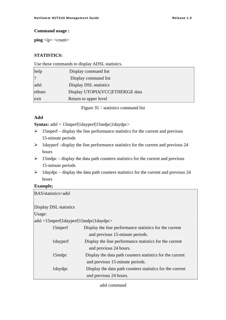
STATISTICS:
Use these commands to display ADSL statistics. help Display command list ? Display command list adsl Display DSL statistics ethuto Display UTOPIA|VCC|ETHER|GE data exit Return to upper level
Figure 35:statistics command list
Adsl Syntax: adsl < 15mperf|1dayperf|15mdpc|1daydpc>
15mperf – display the line performance statistics for the current and previous 15-minute periods
1dayperf –display the line performance statistics for the current and previous 24 hours
15mdpc – display the data path counters statistics for the current and previous 15-minute periods
1daydpc – display the data path counters statistics for the current and previous 24 hours
Example; BAS/statistics>adsl Display DSL statistics Usage: adsl <15mperf|1dayperf|15mdpc|1daydpc> 15mperf Display the line performance statistics for the current and previous 15-minute periods. 1dayperf Display the line performance statistics for the current and previous 24 hours. 15mdpc Display the data path counters statistics for the current and previous 15-minute periods. 1daydpc Display the data path counters statistics for the current and previous 24 hours.
adsl command
61
NetComm NCT240 Management Guide Release 1.0
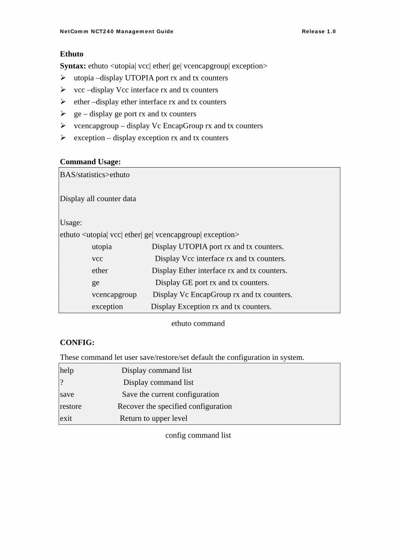
Ethuto Syntax: ethuto <utopia| vcc| ether| ge| vcencapgroup| exception>
utopia –display UTOPIA port rx and tx counters vcc –display Vcc interface rx and tx counters ether –display ether interface rx and tx counters ge – display ge port rx and tx counters vcencapgroup – display Vc EncapGroup rx and tx counters exception – display exception rx and tx counters
Command Usage: BAS/statistics>ethuto Display all counter data Usage: ethuto <utopia| vcc| ether| ge| vcencapgroup| exception> utopia Display UTOPIA port rx and tx counters. vcc Display Vcc interface rx and tx counters. ether Display Ether interface rx and tx counters. ge Display GE port rx and tx counters. vcencapgroup Display Vc EncapGroup rx and tx counters. exception Display Exception rx and tx counters.
ethuto command
CONFIG:
These command let user save/restore/set default the configuration in system. help Display command list ? Display command list save Save the current configuration restore Recover the specified configuration exit Return to upper level
config command list
62
NetComm NCT240 Management Guide Release 1.0
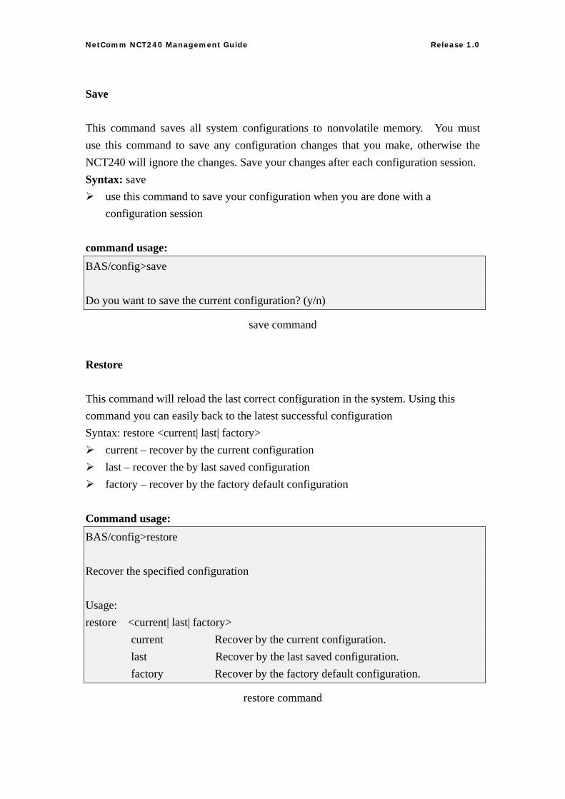
Save
This command saves all system configurations to nonvolatile memory. You must use this command to save any configuration changes that you make, otherwise the NCT240 will ignore the changes. Save your changes after each configuration session. Syntax: save
use this command to save your configuration when you are done with a configuration session
command usage: BAS/config>save Do you want to save the current configuration? (y/n)
save command
Restore
This command will reload the last correct configuration in the system. Using this command you can easily back to the latest successful configuration Syntax: restore <current| last| factory>
current – recover by the current configuration last – recover the by last saved configuration factory – recover by the factory default configuration
Command usage: BAS/config>restore Recover the specified configuration Usage: restore <current| last| factory> current Recover by the current configuration. last Recover by the last saved configuration. factory Recover by the factory default configuration.
restore command
63
NetComm NCT240 Management Guide Release 1.0
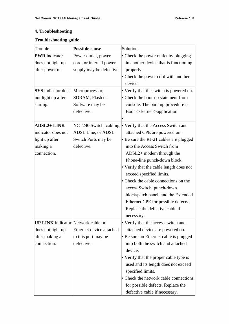
4. Troubleshooting
Troubleshooting guide
Trouble Possible cause Solution PWR indicator does not light up after power on.
Power outlet, power cord, or internal power supply may be defective.
• Check the power outlet by plugging in another device that is functioning properly.
• Check the power cord with another device.
SYS indicator does not light up after startup.
Microprocessor, SDRAM, Flash or Software may be defective.
• Verify that the switch is powered on.• Check the boot-up statement from
console. The boot up procedure is Boot -> kernel->application
• ADSL2+ LINK indicator does not light up after making a connection.
NCT240 Switch, cabling, ADSL Line, or ADSL Switch Ports may be defective.
• Verify that the Access Switch and attached CPE are powered on.
• Be sure the RJ-21 cables are plugged into the Access Switch from ADSL2+ modem through the Phone-line punch-down block.
• Verify that the cable length does not exceed specified limits.
• Check the cable connections on the access Switch, punch-down block/patch panel, and the Extended Ethernet CPE for possible defects. Replace the defective cable if necessary.
UP LINK indicator does not light up after making a connection.
Network cable or Ethernet device attached to this port may be defective.
• Verify that the access switch and attached device are powered on.
• Be sure an Ethernet cable is plugged into both the switch and attached device.
• Verify that the proper cable type is used and its length does not exceed specified limits.
• Check the network cable connections for possible defects. Replace the defective cable if necessary.
64

NetComm NCT240 Management Guide Release 1.0
Cannot ping uplink
65
NetComm NCT240 Management Guide Release 1.0
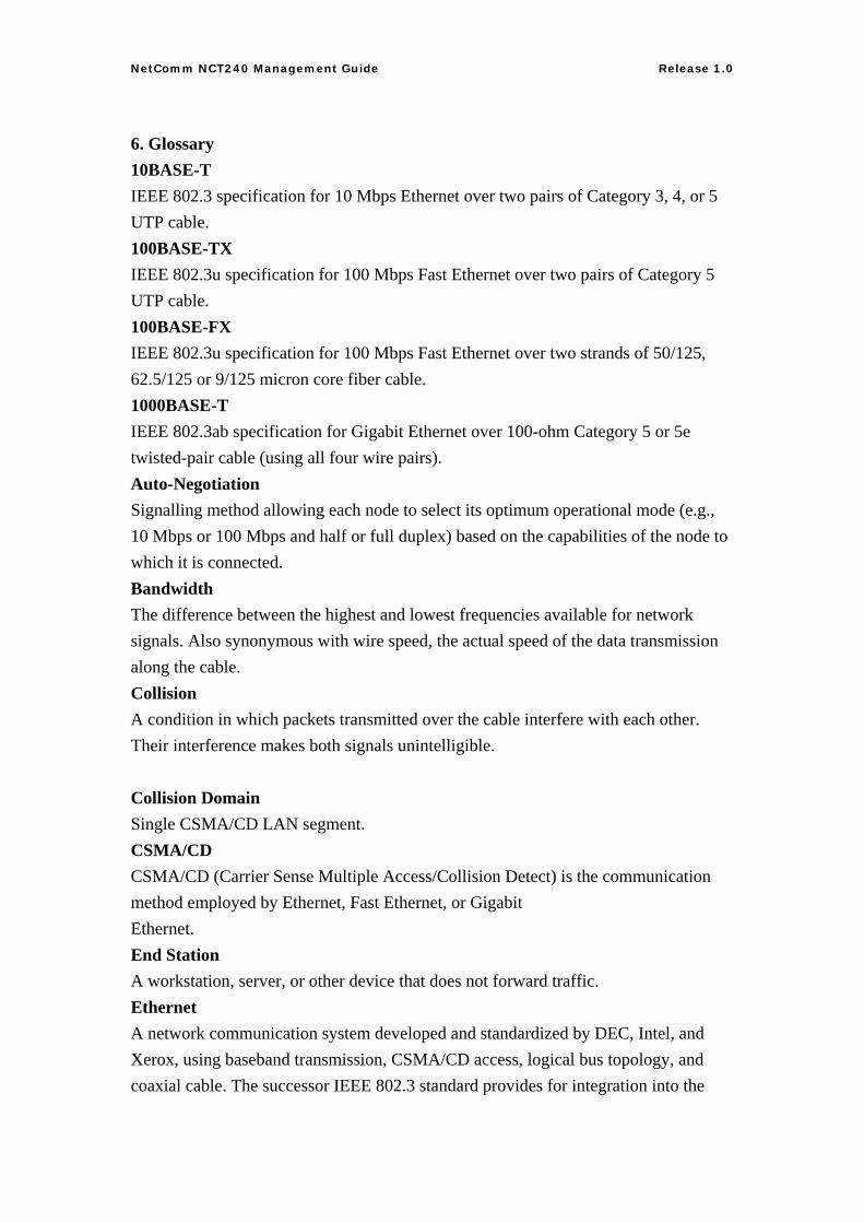
6. Glossary 10BASE-T IEEE 802.3 specification for 10 Mbps Ethernet over two pairs of Category 3, 4, or 5 UTP cable. 100BASE-TX IEEE 802.3u specification for 100 Mbps Fast Ethernet over two pairs of Category 5 UTP cable. 100BASE-FX IEEE 802.3u specification for 100 Mbps Fast Ethernet over two strands of 50/125, 62.5/125 or 9/125 micron core fiber cable. 1000BASE-T IEEE 802.3ab specification for Gigabit Ethernet over 100-ohm Category 5 or 5e twisted-pair cable (using all four wire pairs). Auto-Negotiation Signalling method allowing each node to select its optimum operational mode (e.g., 10 Mbps or 100 Mbps and half or full duplex) based on the capabilities of the node to which it is connected. Bandwidth The difference between the highest and lowest frequencies available for network signals. Also synonymous with wire speed, the actual speed of the data transmission along the cable. Collision A condition in which packets transmitted over the cable interfere with each other. Their interference makes both signals unintelligible. Collision Domain Single CSMA/CD LAN segment. CSMA/CD CSMA/CD (Carrier Sense Multiple Access/Collision Detect) is the communication method employed by Ethernet, Fast Ethernet, or Gigabit Ethernet. End Station A workstation, server, or other device that does not forward traffic. Ethernet A network communication system developed and standardized by DEC, Intel, and Xerox, using baseband transmission, CSMA/CD access, logical bus topology, and coaxial cable. The successor IEEE 802.3 standard provides for integration into the
66
NetComm NCT240 Management Guide Release 1.0
OSI model and extends the physical layer and media with repeaters and implementations that operate on fiber, thin coax and twisted-pair cable. Fast Ethernet A 100 Mbps network communication system based on Ethernet and the CSMA/CD access method. Gigabit Ethernet A 1000 Mbps network communication system based on Ethernet and the CSMA/CD access method. Full-Duplex Transmission method that allows two network devices to transmit and receive concurrently, effectively doubling the bandwidth of that link. IEEE Institute of Electrical and Electronic Engineers. IEEE 802.3 Defines carrier sense multiple access with collision detection (CSMA/CD) access method and physical layer specifications. IEEE 802.3ab Defines CSMA/CD access method and physical layer specifications for 1000BASE-T Fast Ethernet. IEEE 802.3u Defines CSMA/CD access method and physical layer specifications for 100BASE-TX Fast Ethernet. IEEE 802.3x Defines Ethernet frame start/stop requests and timers used for flow control on full-duplex links. IEEE 802.3z Defines CSMA/CD access method and physical layer specifications for 1000BASE Gigabit Ethernet. Local Area Network (LAN) A group of interconnected computer and support devices. LAN Segment Separate LAN or collision domain. LED Light emitting diode used for monitoring a device or network condition. Local Area Network A group of interconnected computers and support devices. Media Access Control (MAC)
67
NetComm NCT240 Management Guide Release 1.0
A portion of the networking protocol that governs access to the transmission medium, facilitating the exchange of data between network nodes. MDF (Main Distribution Frame) Equipment where outside telephone lines are terminated at a building or site. MIB An acronym for Management Information Base. It is a set of database objects that contains information about the device. MPOE (Minimum or Main Point of Entry) The location in a building where cables from the telephone service provider are terminated. Network Diameter Wire distance between two end stations in the same collision domain. Private Branch Exchange (PBX) A telephone exchange local to a particular organization who use, rather than provide, telephone services. POTS Plain Old Telephone Service. Redundant Power Unit (RPU) A backup power supply that automatically takes over in case the primary power supply should fail. RJ-45 Connector A connector for twisted-pair wiring. Splitter A filter to separate DSL signals from POTS signals to prevent mutual interference. Switched Ports Ports that are on separate collision domains or LAN segments. Transmission Control Protocol/Internet Protocol (TCP/IP) Protocol suite that includes TCP as the primary transport protocol, and IP as the network layer protocol. UTP Unshielded twisted-pair cable. ADSL asymmetric data rate Digital Subscriber Line: A family of digital telecommunications protocols designed to allow high speed data communication at data rates deliver data rates up to 25 Mbps downstream and 1 Mbps upstream with corresponding maximum reach 18K feet of 24 gauge twisted pair cable over the existing copper telephone lines between end-users and telephone companies. Virtual LAN (VLAN)
68

NetComm NCT240 Management Guide Release 1.0
A Virtual LAN is a collection of network nodes that share the same collision domain regardless of their physical location or connection point in the network. A VLAN serves as a logical workgroup with no physical barriers, allowing users to share information and resources as though located on the same LAN.
69

Product WarrantyNetComm products have a standard 12 months warranty from date of purchase. However some products have an extended warranty option, via registering your product online at the NetComm website www.netcomm.com.au.
Technical SupportIf you have any technical difficulties with your product, please refer to the support section of our website.
www.netcomm.com.au/supportNote: NetComm Technical Support for this product only covers the basic installation and features outlined in the Quick Start Guide. For further information regarding the advanced features of this product, please refer to the configuring
sections in the User Guide or contact a Network Specialist.
NETCOMM LIMITED PO Box 1200, Lane Cove NSW 2066 AustraliaP: 02 9424 2070 F: 02 9424 2010
E: [email protected] W: www.netcomm.com.au
DYNALINK NZ 224b Bush Road, Albany, Auckland, New Zealand P: 09 448 5548 F: 09 448 5549E: [email protected] W: www.dynalink.co.nz
www.dynalink.co.nz
www.dynalink.co.nz
Trademarks and registered trademarks are the property of NetComm Limited or their respective owners. Specifications are subject to change without notice. Images shown may vary slightly from the actual product.