Embed Size (px)
Citation preview
UltraCade Technologies1281 Wayne AvenueSan Jose, CA 95131
Ph: (408) 4368885 Fax: (408) 7156183www.ultracade.com [email protected]
UltraCade Technologies USBlinx User Documentation version 02H 7/23/2005Document 040USBLNXMUCT © & ™ 200105 UltraCade Technologies. All Rights Reserved
USBlinx™User Documentation
PC / JAMMA InterfacePart Number: 990USBlinxUCT02H
Version 02HMay 24, 2005

UltraCade Technologies USBlinx User Documentation version 02H 7/23/2005Document 040USBLNXMUCT © & ™ 200105 UltraCade Technologies. All Rights Reserved
2
Table of Contents
!!! IMPORTANT NOTE !!! 3
Legal Statement 3
Package Contents 3
Overview 3
Board Image 4
Board Layout 5
Power 6
PS/2 6
USB 7
Digital Outputs 8
Video 9
Audio 10
Watchdog Circuit 10
Key Map 11
JAMMA Interface 12
Trackball / Spinner Interface 13
Additional I/O Connectors 14
PCB Connectors 15
Revision History 16
Contact Information 16

UltraCade Technologies USBlinx User Documentation version 02H 7/23/2005Document 040USBLNXMUCT © & ™ 200105 UltraCade Technologies. All Rights Reserved
3
!!! IMPORTANT NOTE !!!This document refers to version 02H of the USBlinx interface board. 02H is the combination of PCBversion B, Hub firmware version H and Trackball firmware version B. Other versions of the PCBand firmware may differ from the details presented in this document. Please refer to the correctdocumentation for your specific hardware (see ‘Revision History’ on page 16).
Legal StatementThe USBlinx PCB is copyright © & trademark ™ 200105 by UltraCade Technologies, All RightsReserved. The USBlinx PCB and algorithms are Patent Pending. USBlinx is a trademark ofUltraCade Technologies.
Package Contents
• User Documentation • USBlinx PCB
• Video Cable (VGA) 3ft • Audio Cable (3.5mm jack) 6ft
• USB Cable 6ft • PS/2 Cable 3ft
• Reset cable (2pin) 2ft • Free Gift Offer Card
OverviewThe USBlinx interface card is part of UltraCade Technologies’ series of JAMMA compatibleinterface cards. For more information and a full list of current products, please go towww.ultracade.com.
The USBlinx provides a standard JAMMA interface for simple replacement of arcade motherboardswith a more reliable, configurable and upgradeable PC based systems.
The standard JAMMA interface supports two players with four buttons each. The USBlinx cansupport and also enhance the standard JAMMA interface with two optional extended interfaces.The first additional predefined interface supports two players, each with six fire buttons, a trackballand a spinner. The second additional predefined interface supports four players, each with four firebuttons, and two players with a trackball and a spinner each. Custom interfaces can also bedefined using the 48 inputs and 4 outputs.
The digital inputs and outputs can be transferred to and from the PC via the PS/2 or USB ports.The trackball and spinner data may only be sent via the USB port. All of the digital inputs andoutputs, 2 trackballs and 2 spinners may be simultaneously connected to the USB port with nodegradation in performance; no PS/2 connection is required.

UltraCade Technologies USBlinx User Documentation version 02H 7/23/2005Document 040USBLNXMUCT © & ™ 200105 UltraCade Technologies. All Rights Reserved
4
The 4 digital outputs are designed for +12v operation and include surge protection for electromechanical devices. Devices requiring +5v may be used; however, care is required as the surgeprotection will be minimal.
A watchdog circuit enables the USBlinx to detect a system crash and initiate a complete systemrestart. Amplifications are also provided for PC to arcade video and PC to arcade audio.
Board Image

UltraCade Technologies USBlinx User Documentation version 02H 7/23/2005Document 040USBLNXMUCT © & ™ 200105 UltraCade Technologies. All Rights Reserved
5
Board Layout

UltraCade Technologies USBlinx User Documentation version 02H 7/23/2005Document 040USBLNXMUCT © & ™ 200105 UltraCade Technologies. All Rights Reserved
6
PowerThe USBlinx has two potential sources of power which must not be connected simultaneously. Thesource of power depends on the application. Some JAMMA harnesses are selfpowered, whileothers require power to be supplied from the USBlinx. In the former case, the USBlinx is poweredfrom the JAMMA connector and the PC HDD (hard disk drive) connector (J1) must not beconnected. In the latter case, the USBlinx is powered from a standard PC HDD connector, whichthen powers the JAMMA harness. NOTE: be sure the JAMMA harness is not selfpoweredbefore connecting the PC HDD power connector to the USBlinx.
Another potential power source is the USB connector; however, no power from the USB connectoris used on the USBlinx.
Irrespective of the method of connecting power, the USBlinx is protected from the power source by5A fuses on both the +12v and +5v lines. If power is connected using the PC HDD powerconnector, then the USBlinx and the JAMMA harness are independently protected from the powersource (J1); there are four fuses, for the +5v and the +12v lines to both the USBlinx and the JAMMAharness. If the JAMMA harness is the power source, the +5v and +12v lines each pass through 2fuses to get to the USBlinx proper.
The USBlinx does not support the 5v JAMMA connection. If the JAMMA harness is the powersource, then the 5v signal is simply unused. If the PC HDD power connector is the power source,then the 5v JAMMA connection is left unconnected, and hence not powered.
PS/2When the PS/2 cable is connected between the USBlinx and the PC’s PS/2 keyboard port, thedigital inputs and outputs are sent over the PS/2 interface irrespective of the connection of a USBcable (trackball and spinner data is always sent via USB). However, it is recommended that thePS/2 cable is NOT connected when a USB connection is available. For mappings of virtualkeyboard keys to digital inputs and outputs, see the sections on the Key Map, JAMMA Interface,and Additional I/O Connectors.
The USBlinx PS/2 interface is the same as a boot keyboard device. All traditional keyboards are'boot keyboards', which means that they have a specific communication format that is supported bythe PC’s BIOS.
A PS/2 datum is generated whenever the state of the inputs changes. The datum is a keyboardscan code and represents the key and whether it was pressed or released. All keys, includingmodifier (shift, control, etc.) and special (vol+, vol, sleep, etc.) keys generate a unique scan codewhen either pressed or released.
NOTE1: If used, ensure that the PS/2 cable is connected to the PC’s keyboard port, which inmodern PCs is colored mauve.
NOTE2: The PS/2 cable is only required when connecting to a device that does not supportUSB. If USB is available, connect the USBlinx through the USB cable only.

UltraCade Technologies USBlinx User Documentation version 02H 7/23/2005Document 040USBLNXMUCT © & ™ 200105 UltraCade Technologies. All Rights Reserved
7
USBWhen the PS/2 cable is connected between the USBlinx and the PC’s PS/2 keyboard port, thedigital inputs and outputs are sent over the PS/2 interface irrespective of the connection of a USBcable (trackball and spinner data is always sent via USB). However, it is recommended that thePS/2 cable is NOT connected when a USB connection is available. For mappings of virtualkeyboard keys to digital inputs and outputs, see the sections on the Key Map, JAMMA Interface,and Additional I/O Connectors.
The USBlinx USB keyboard interface is the same as a boot keyboard device. All traditionalkeyboards are 'boot keyboards', which means that they have a specific communication format thatis supported by the PC’s BIOS. The trackball and spinner USB interface is only active after bootup,and enumerate as two Windows compatible mice. However, Windows does not deal well with twopointer devices attached simultaneously!
Bringing up a USB design with the USBlinx is made simple by all three devices conforming tostandard Windows compatible devices. The data from the USBlinx may therefore be obtained bysimply reading from the keyboard and the two mice.
The USB communication pipes are standard and relatively simple, although the device driver mayabstract away even this level of complexity. Each of the three separate devices is enumeratedusing two endpoints. All control commands are sent through ‘Endpoint 0’. Upstream data is sentfrom the PC using the ‘Endpoint 0’ ‘Set Report’ command followed by the data (also on ‘Endpoint0’). The downstream data is sent from the USBlinx using an ‘isochronous USB pipe on Endpoint 1’.
The USBlinx USB keyboard is required to support 48 individual inputs from the outside world(joystick, buttons, etc) and 4 outputs to the outside world (lights, coin counter, etc). However, mostUSB keyboards support very limited data communication.
USB keyboards receive just one byte of data to output, of which only three bits are generally used;these are for the display LEDs: Caps, Num and Scroll Lock. Despite this limitation, the standardconfiguration is enough for the requirements of the USBlinx outputs; see the section on DigitalOutputs for more information.
The USBlinx inputs, however, do present a problem. Unlike PS/2 keyboards that send changeevents, USB keyboards send a list of the keys that are currently depressed; generally only up to amaximum of 6 keys. The 8 byte packet is started by 8 bits for the modifier keys (shift, control, etc),the second byte is reserved, and the final six bytes contain the six keys currently pressed. This isnot enough for an arcade game where 2 or even 4 players may be simultaneously moving joysticksand buttons. The solution is to instantiate the USBlinx as a USB keyboard that supports 18simultaneously pressed keys. Combined with the 5 modifier keys currently used in the USBlinx KeyMap, this allows the USBlinx USB virtual keyboard to support 23 simultaneously depressed keys,which more than covers even extremely unlikely scenarios.

UltraCade Technologies USBlinx User Documentation version 02H 7/23/2005Document 040USBLNXMUCT © & ™ 200105 UltraCade Technologies. All Rights Reserved
8
Standard USB Keyboard Packet Byte USBlinx KeyboardModifier Keys 1 1 Modifier KeysReserved 1 2 Reserved6 Keys Pressed 1 38 6 Keys Pressed
n/a 2 18 8 Keys Pressed
n/a 3 14 4 Keys Pressed
Digital OutputsAn application sets the USBlinx outputs by sending one byte over either the PS/2 or USBconnection. If the PS/2 port is used, an output transfer is initiated and then one byte is transferred.If USB is used, the output transfer is initiated by sending the USB Set Report command(BMRequestType 2116 and BMRequest 0916) down the control pipe (Endpoint 0) first, followed bythe data packet. The first byte of the data packet is used and the rest is ignored.
The USBlinx supports 4 outputs implemented as decoupled ground enables using FET transistors.Setting an output simply enables the corresponding circuit ground; conversely, clearing the outputdisables the circuit ground. When connecting a device, connect the positive terminal to the relevantvoltage supply, and the negative (or ground) terminal to the relevant output pin on the USBlinx.Enabling that output will enable the circuit, and therefore the device. The connections on theUSBlinx output connector (J10) are shown in the table at the end of this section.
Decoupling with FETs enables the only limitation on the current draw to be from the power supplyitself (the FETs have maximum ratings of 1.6 amps continuous and 10 amp pulse). In addition, a+12v surge protector is included as part of each output; this enables the safe use of +12v electromechanical devices. NOTE: the surge protector has a lesser effect on +5v devices.
Of the 8 outputs, only 4 are currently connected, with the remainder reserved for future expansion.The JAMMA standard defines the 4 outputs as:
• Coin counter 1 connected through component side pin 8
• Coin lock 1 connected through component side pin 9
• Coin counter 2 connected through solder side pin 8
• Coin lock 2 connected through solder side pin 9
Access to these 4 outputs is achieved through the standard keyboard method. Irrespective ofwhether the USBlinx is connected through PS/2 or USB port, a full byte of data is sent from the PCto the ‘virtual’ keyboard. Of these 8 bits the base format is that the top 5 bits are reserved, with thelower 3 bits used for the 3 keyboard LEDs (Num, Caps and Scroll lock). The PS/2 and USBstandards unsurprisingly define the three outputs in differing formats.
UltraCade Technologies USBlinx User Documentation version 02H 7/23/2005Document 040USBLNXMUCT © & ™ 200105 UltraCade Technologies. All Rights Reserved
9
The USBlinx uses the NumLock output to reset its internal watchdog circuit (see the relevantsection for more information on the watchdog circuit). The 4 outputs from the USBlinx are thereforesent by the PC using the remaining 2 LED outputs in addition to the adjacent 2 reserved bits. The 8bit byte sent from the PC to the USBlinx therefore has the format:
PS/2 output byte[7:0] reserved reserved reserved coinlock 2
coincounter 2
caps lockLED
num lockLED
scrolllock LED
USB output byte[7:0] reserved reserved reserved coinlock 2
coincounter 2
scrolllock LED
caps lockLED
num lockLED
The outputs connector on the USBlinx (J10) has the following pinout:
Pin Usage Virtual Keyboard Accessed By1 Ground n/a n/a2 +12v n/a n/a3 Coin Counter 1 Scroll Lock LED Bit 0 if PS/2 Bit 2 if USB4 Coin Lock 1 Caps Lock LED Bit 2 if PS/2 Bit 1 if USB5 Coin Counter 2 n/c Bit 36 Coin Lock 2 n/c Bit 47 Output 5 n/c reserved8 Output 6 n/c reserved9 Output 7 n/c reserved10 Output 8 n/c reserved11 +12v n/a n/a12 Ground n/a n/a
VideoNOTE: No resolution or frequency conversion is done by the USBlinx. The only processingof the video signal is amplification on the red, green and blue signals and the combination ofseparate horizontal and vertical syncs into a composite sync signal. For frequency andresolution conversion, please refer to the UltraCade uVC video converter atwww.ultracade.com.
The video circuit in the USBlinx is used when the target monitor is either an arcade CGA or EGAmonitor. The USBlinx provides three necessary functions to convert PC signals into arcade monitorsignals. Firstly, the BIOS has control of the video during the PC bootup phase and may outputincompatible signals. Secondly, the voltages of the RGB signals are different. Finally, thesynchronization format may differ.
During PC bootup, the application, and even the operating system, has no control over the videomode. The BIOS uses whatever default mode the motherboard supports. There is therefore thepotential that these modern synchronization signals may damage older style arcade monitors that

UltraCade Technologies USBlinx User Documentation version 02H 7/23/2005Document 040USBLNXMUCT © & ™ 200105 UltraCade Technologies. All Rights Reserved
10
do not support such fast synchronization signals. The USBlinx therefore disables thesynchronization signals from propagating to the target monitor until the DDC signals enable it. DDCconsists of clock (SCL) and data (SDA) lines, and is a mostly unregulated method for monitors toidentify themselves by sending and receiving configuration information. The SDA line defaults tohigh, and the USBlinx needs to see the SDA line pulled low to enable the pass through of the videosynchronization signals.
Both PC and arcade monitors use +5v synchronization signals, however, the voltage ranges aredifferent in the red, green and blue signals. The USBlinx therefore provides a video amplifier forconverting the PC’s 0.7vpp RGB signals (input into the DB15 connector J11) to the arcade monitor’s5vpp signals (output through the JAMMA connector).
The type of synchronization signals used by arcade monitors can differ. All PCs produce separatehorizontal and vertical synchronization signals, while some arcade monitors require just onecomposite signal. The USBlinx therefore combines separate synchronization signals (input into theDB15 connector) into a composite signal (output through the JAMMA connector).
AudioStandard PC audio output is a preamplified signal through a 3.5mm stereo jack. A standard arcadecabinet just contains one or two 8 speakers, accessed through the JAMMA connector pins 10(left) and 11 (right). The positive audio is on the component side and negative on the solder side.
The USBlinx bridges these disparate standards. A standard 3.5mm stereo jack socket is providedto connect the PC audio input. The audio is then amplified by a 2x37W audio amplifier. Finally, theamplified audio is routed to the speakers through the standard pins of the JAMMA connector.
Mono output is available by simply joining the left and right pins at the 3.5mm jack on the USBlinx.Fully amplified mono audio signals are then available at the JAMMA connector on both of the leftand the right positive/negative pair.
Watchdog CircuitIn the event of a PC crash, the USBlinx is designed to reboot both the PC and itself. To facilitatethis, a two pin connector must be used to connect the USBlinx reset connector (J4) to the PC’sreset switch (locate this by using the motherboard’s documentation).
The USBlinx constantly counts up to about half a minute (the exact number is 720016 milliseconds,which is 29.184 seconds). When that value is reached, the USBlinx sends a reset pulse (225microsecond pulse) to the PC and then reboots itself. Therefore, the PC must reset the USBlinxwatchdog at least every 29 seconds. The USBlinx watchdog’s reset count is restarted by togglingthe ‘virtual’ keyboard’s NumLock LED. The NumLock LED bit is in different positions in the PS/2and USB standards. In the PS/2 standard the NumLock LED is the middle LED bit (bit 1 inbyte[7:0]). In the USB standard the NumLock LED is the least significant bit (bit 0 in byte[7:0]).
The USBlinx reset switch is bidirectional, such that the PC can pull the reset switch low and rebootboth the USBlinx and itself, and also the USBlinx can pull the reset switch low and reboot both thePC and itself.
UltraCade Technologies USBlinx User Documentation version 02H 7/23/2005Document 040USBLNXMUCT © & ™ 200105 UltraCade Technologies. All Rights Reserved
11
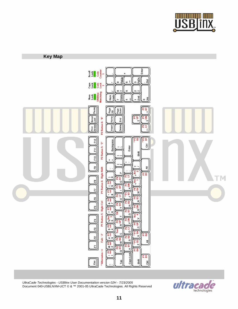
Key Map
UltraCade Technologies USBlinx User Documentation version 02H 7/23/2005Document 040USBLNXMUCT © & ™ 200105 UltraCade Technologies. All Rights Reserved
12
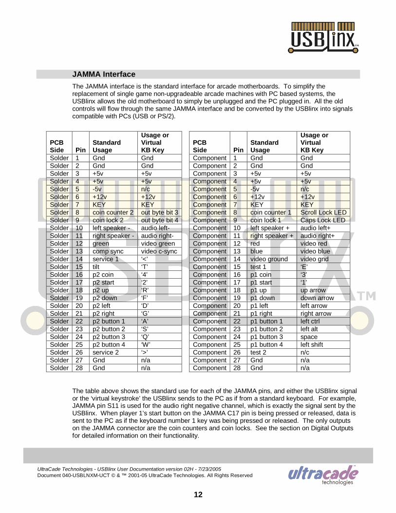
JAMMA InterfaceThe JAMMA interface is the standard interface for arcade motherboards. To simplify thereplacement of single game nonupgradeable arcade machines with PC based systems, theUSBlinx allows the old motherboard to simply be unplugged and the PC plugged in. All the oldcontrols will flow through the same JAMMA interface and be converted by the USBlinx into signalscompatible with PCs (USB or PS/2).
PCBSide Pin
StandardUsage
Usage orVirtualKB Key
PCBSide Pin
StandardUsage
Usage orVirtualKB Key
Solder 1 Gnd Gnd Component 1 Gnd GndSolder 2 Gnd Gnd Component 2 Gnd GndSolder 3 +5v +5v Component 3 +5v +5vSolder 4 +5v +5v Component 4 +5v +5vSolder 5 5v n/c Component 5 5v n/cSolder 6 +12v +12v Component 6 +12v +12vSolder 7 KEY KEY Component 7 KEY KEYSolder 8 coin counter 2 out byte bit 3 Component 8 coin counter 1 Scroll Lock LEDSolder 9 coin lock 2 out byte bit 4 Component 9 coin lock 1 Caps Lock LEDSolder 10 left speaker audio left Component 10 left speaker + audio left+Solder 11 right speaker audio right Component 11 right speaker + audio right+Solder 12 green video green Component 12 red video redSolder 13 comp sync video csync Component 13 blue video blueSolder 14 service 1 ‘<’ Component 14 video ground video gndSolder 15 tilt ‘T’ Component 15 test 1 ‘E’Solder 16 p2 coin ‘4’ Component 16 p1 coin ‘3’Solder 17 p2 start ‘2’ Component 17 p1 start ‘1’Solder 18 p2 up ‘R’ Component 18 p1 up up arrowSolder 19 p2 down ‘F’ Component 19 p1 down down arrowSolder 20 p2 left ‘D’ Component 20 p1 left left arrowSolder 21 p2 right ‘G’ Component 21 p1 right right arrowSolder 22 p2 button 1 ‘A’ Component 22 p1 button 1 left ctrlSolder 23 p2 button 2 ‘S’ Component 23 p1 button 2 left altSolder 24 p2 button 3 ‘Q’ Component 24 p1 button 3 spaceSolder 25 p2 button 4 ‘W’ Component 25 p1 button 4 left shiftSolder 26 service 2 ‘>’ Component 26 test 2 n/cSolder 27 Gnd n/a Component 27 Gnd n/aSolder 28 Gnd n/a Component 28 Gnd n/a
The table above shows the standard use for each of the JAMMA pins, and either the USBlinx signalor the ‘virtual keystroke’ the USBlinx sends to the PC as if from a standard keyboard. For example,JAMMA pin S11 is used for the audio right negative channel, which is exactly the signal sent by theUSBlinx. When player 1’s start button on the JAMMA C17 pin is being pressed or released, data issent to the PC as if the keyboard number 1 key was being pressed or released. The only outputson the JAMMA connector are the coin counters and coin locks. See the section on Digital Outputsfor detailed information on their functionality.
UltraCade Technologies USBlinx User Documentation version 02H 7/23/2005Document 040USBLNXMUCT © & ™ 200105 UltraCade Technologies. All Rights Reserved
13
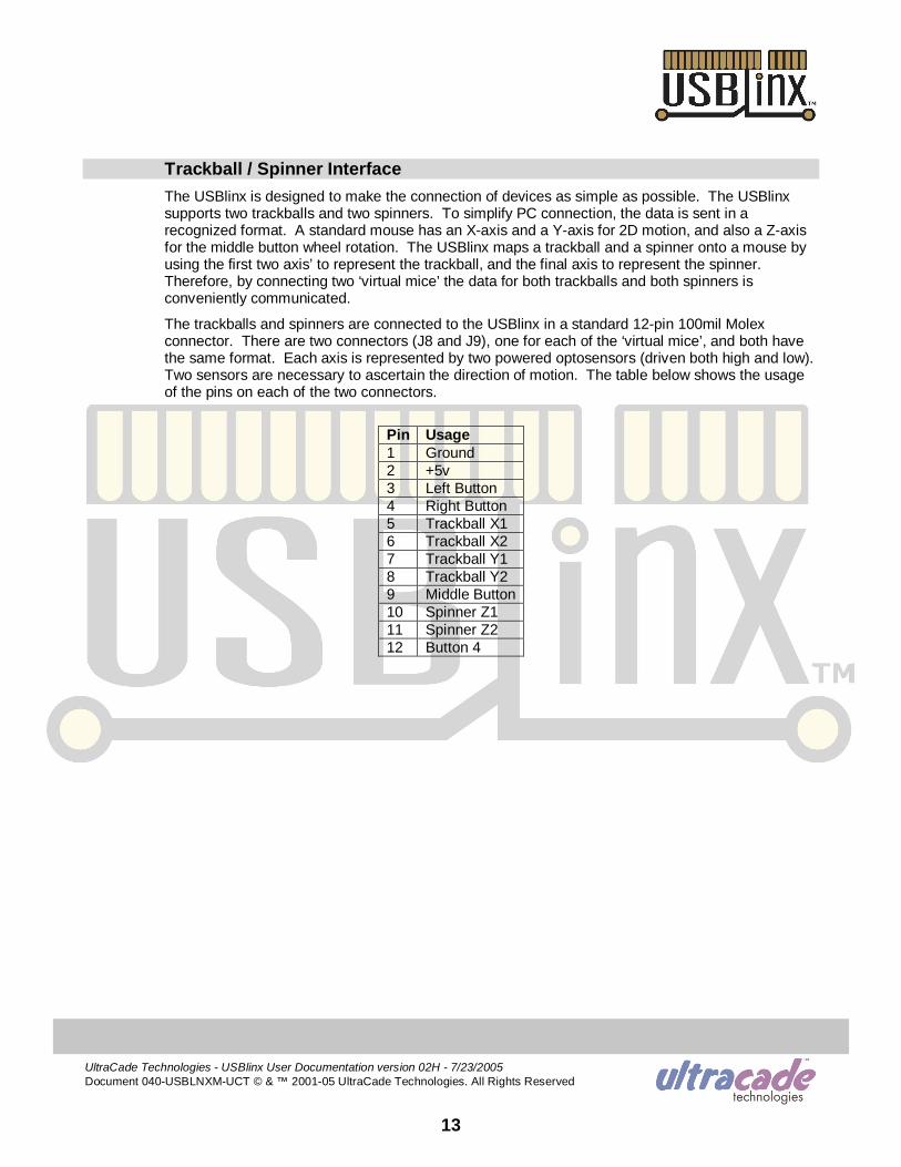
Trackball / Spinner InterfaceThe USBlinx is designed to make the connection of devices as simple as possible. The USBlinxsupports two trackballs and two spinners. To simplify PC connection, the data is sent in arecognized format. A standard mouse has an Xaxis and a Yaxis for 2D motion, and also a Zaxisfor the middle button wheel rotation. The USBlinx maps a trackball and a spinner onto a mouse byusing the first two axis’ to represent the trackball, and the final axis to represent the spinner.Therefore, by connecting two ‘virtual mice’ the data for both trackballs and both spinners isconveniently communicated.
The trackballs and spinners are connected to the USBlinx in a standard 12pin 100mil Molexconnector. There are two connectors (J8 and J9), one for each of the ‘virtual mice’, and both havethe same format. Each axis is represented by two powered optosensors (driven both high and low).Two sensors are necessary to ascertain the direction of motion. The table below shows the usageof the pins on each of the two connectors.
Pin Usage1 Ground2 +5v3 Left Button4 Right Button5 Trackball X16 Trackball X27 Trackball Y18 Trackball Y29 Middle Button10 Spinner Z111 Spinner Z212 Button 4
UltraCade Technologies USBlinx User Documentation version 02H 7/23/2005Document 040USBLNXMUCT © & ™ 200105 UltraCade Technologies. All Rights Reserved
14
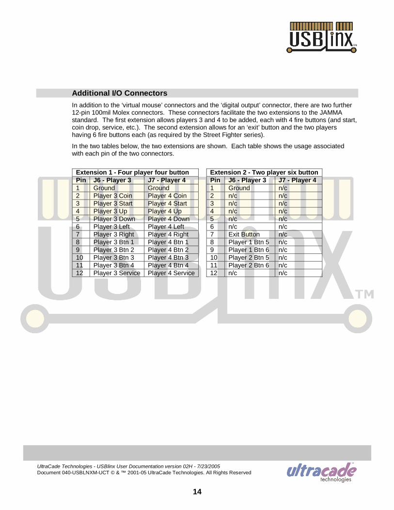
Additional I/O ConnectorsIn addition to the ‘virtual mouse’ connectors and the ‘digital output’ connector, there are two further12pin 100mil Molex connectors. These connectors facilitate the two extensions to the JAMMAstandard. The first extension allows players 3 and 4 to be added, each with 4 fire buttons (and start,coin drop, service, etc.). The second extension allows for an ‘exit’ button and the two playershaving 6 fire buttons each (as required by the Street Fighter series).
In the two tables below, the two extensions are shown. Each table shows the usage associatedwith each pin of the two connectors.
Extension 1 Four player four button Extension 2 Two player six buttonPin J6 Player 3 J7 Player 4 Pin J6 Player 3 J7 Player 41 Ground Ground 1 Ground n/c2 Player 3 Coin Player 4 Coin 2 n/c n/c3 Player 3 Start Player 4 Start 3 n/c n/c4 Player 3 Up Player 4 Up 4 n/c n/c5 Player 3 Down Player 4 Down 5 n/c n/c6 Player 3 Left Player 4 Left 6 n/c n/c7 Player 3 Right Player 4 Right 7 Exit Button n/c8 Player 3 Btn 1 Player 4 Btn 1 8 Player 1 Btn 5 n/c9 Player 3 Btn 2 Player 4 Btn 2 9 Player 1 Btn 6 n/c10 Player 3 Btn 3 Player 4 Btn 3 10 Player 2 Btn 5 n/c11 Player 3 Btn 4 Player 4 Btn 4 11 Player 2 Btn 6 n/c12 Player 3 Service Player 4 Service 12 n/c n/c

UltraCade Technologies USBlinx User Documentation version 02H 7/23/2005Document 040USBLNXMUCT © & ™ 200105 UltraCade Technologies. All Rights Reserved
15
PCB ConnectorsThis section provides the part numbers and pin assignments for the mating connectors to all of theconnectors on the PCB.
PCBRef
PCB ConnectorDescription
Required MateDescription Parts Required Supplier Part Number
Inc. inpacket
J1 Power PC HDD FemalePC HDD connectorPin1 +12vdcPin2 GroundPin3 GroundPin4 +5vdc
1 x Extension 2ftOR
1 x Female housing4 x Female terminal4 x Wire1 x Male housing4 x Male terminal
UltraCade
AMPAMP{any}AMPAMP
115HDDPWRCBL
14804240606171n/a14804260616181
no
nonononono
J2 JAMMA seeJAMMA Intface**
Female JAMMA** 1 x JAMMA harness Happ 80510000 no
J3 Reset switch <removed> n/a n/a n/a noJ4 Reset switch Female 2pin
118mil microfitPin1 ResetPin2 Ground
1 x Custom cable 2ftOR
1 x Female housing2 x Female terminal
UltraCade
MolexMolex
115USBRSTCBL
430250200430300010
yes
nono
J5 USB uplink USBB plug(USBA = PC plug)
USB A to B 6ftUSB A to B 10ftUSBA extension
UltraCadeUltraCadeusbgear
115USB06ABCBL115USB10ABCBLUSBG3FTE
yesnono
J6 Player 3 seeAdditional I/O**
Female 12pin100mil header**
1 x Female housing12 x Female terminal
MolexMolex
2201212708500108
nono
J7 Player 4 seeAdditional I/O**
Female 12pin100mil header**
1 x Female housing12 x Female terminal
MolexMolex
2201212708500108
nono
J8 Trackball 1 seeTrkball Interface**
Female 12pin100mil header**
1 x Female housing12 x Female terminal
MolexMolex
2201212708500108
nono
J9 Trackball 2 seeTrkball Interface**
Female 12pin100mil header**
1 x Female housing12 x Female terminal
MolexMolex
2201212708500108
nono
J10 Digital outputs see Digital Outs**
Female 12pin100mil header**
1 x Female housing12 x Female terminal
MolexMolex
2201212708500108
nono
J11 Video input Male, DSub 15pinStandard PC video
Std PC video 3ftExtension Cable
UltraCadeAssmann
115VGA3MMCBLAK3222
yesno
J12 USB downlink x 2 <removed> n/a n/a n/a noJ13 PS/2 Keyboard Male PS/2 1 x PS/2 cable 3ft UltraCade 115PS2KEYBCBL yesJ14 PS/2 Mouse <removed> n/a n/a n/a noJ15 Audio input Male, stereo
3.5mm jack1 x PC audio 6ft UltraCade 115AUDMINICBL yes
J16 Config Jumpers <removed> n/a n/a n/a noJ17 Config Jumpers <removed> n/a n/a n/a no
** for pin connection details, see the relevant section (Digital Outputs, JAMMA Interface,Trackball / Spinner Interface, Additional I/O Connectors)
UltraCade Technologies USBlinx User Documentation version 02H 7/23/2005Document 040USBLNXMUCT © & ™ 200105 UltraCade Technologies. All Rights Reserved
16
Revision History• Version 02H. PCB version B. Trackball firmware version B. Hub firmware version H:
o 05/24/2005, DT. First release of the user documentation.
Contact Information
UltraCade Technologies1281 Wayne AvenueSan Jose, CA 95131
Ph: (408) 4368885 Fax: (408) 7156183WEB: http://www.ultracade.com EMAIL: [email protected]
Document Number: 040USBLNXMUCT