Embed Size (px)
Citation preview

USB Radio ClockRev. 1.0
Construction Manual(c) 2009 Reusch Elektronik, Dipl.-Ing. (FH) Rainer Reusch
Homepage:http://re.reworld.eu/en/products/usbdcf77/
Created: 2009-08-14Last change: 2009-12-04

Contents1. Introduction......................................................................................................................................12. Parts of the Kit..................................................................................................................................1
2.1 Bill of Material...........................................................................................................................12.2 Parts List....................................................................................................................................3
3. Suitable DCF-Modules.....................................................................................................................44. Schematic.........................................................................................................................................55. Parts Placement................................................................................................................................66. DCF Module Placement...................................................................................................................77. Design Variations..............................................................................................................................8
7.1 Full Equipment..........................................................................................................................87.2 No Battery Voltage Measure......................................................................................................87.3 No Real Time Clock..................................................................................................................8
8. Starting Up........................................................................................................................................98.1 First Test and Startup.................................................................................................................98.2 Final Test and Installation..........................................................................................................9
9. Links...............................................................................................................................................1010. Statement and Disclaimer.............................................................................................................10
This document is copyright protected. All rights reserved.
Reusch ElektronikDipl.-Ing. (FH) Rainer ReuschBlumenstrasse 13
D-88097 EriskirchGermany
Homepage:http://www.reusch-elektronik.de
E-Mail:[email protected]

Reusch Elektronik USB Radio Clock
1. IntroductionThe USB Radio Clock is a compact gadget to adjust the real time clock of any personal computer with the operating system “Windows”. The USB Radio Clock is only designed for this purpose, so there is abandoned for a display. Only a two colour LED shows the signal receiving situation. The features of this USB radio clock:
• connection to PC and powered via USB interface
• precisely time based on DCF77 (Mainflingen near Frankfurt/Main, Germany)
• precisely time at power on and when no DCF77 signal available through battery buffered internal real time clock (always synchronized on available signal, when powered)
• ability to measure backup battery voltage
• a comfortable software for Microsoft “Windows” for automatic synchronization of the system time
“Real time clock” and “battery voltage measure” are available in the full equipped gadget. In options, this equipment can be omitted.
This manual describes, how to mount Your “USB Radio Clock” kit. Only conventional (wired, no SMD) parts are used, so only an ordinary soldering iron for electronic devices is required. The assembling of this kit is not difficult, but you should have some experience in assembling electronic gadgets. Note, that Reusch Elektronik can't give any liability for proper working. Please buy the professional assembled and approved gadget, if you are not confidential in your own purposes.
2. Parts of the Kit
2.1 Bill of MaterialThe kit should contain the following parts. Please check, before you start assembling.
Pcs. Part Comment bag
2 Resistor 68Ω 1
1 Resistor 120Ω 1
1 Resistor 150Ω 1
1 Resistor 1.5kΩ 1
2 Resistor 2.7kΩ 1
2 Resistor 4.7kΩ 1
1 Resistor 5.6kΩ 1
3 Resistor 10kΩ 4 pcs. with DCF module from Conrad 1
1 Resistor 33kΩ 1
1 Resistor 100kΩ 1
1 Resistor 120kΩ 1
2 Ceramic capacitor 22pF 1
1 Foil capacitor 15nF 1
USBDCF77_Construction Page 1

Reusch Elektronik USB Radio Clock
4 Ceramic capacitor 100nF 1
2 Electrolytic capacitor 10µF/16V 1
1 Electrolytic capacitor 47µF/16V 1
1 Inductor 10µH 1
2 Schottky diode BAT43 or BAT42 2
1 Suppressor diode P6KE6V8A 2
4 Diode BAW76 2
1 LED L-59EGW green/red, 20mA, common cathode 2
1 FET BSS110 or BS250 2
1 Transistor BC548B or BC237, BC238, BC547 2
2 Transistor BC307A or BC308, BC557, BC558 2
1 Integrated circuit DS1337 2
1 Integrated circuit ATTINY861-20PU programmed with firmware 2
1 Integrated circuit TS2950CT-3.3 or LE33CZ 2
1 Miniature crystal 32.768kHz 6pF 2
1 Crystal 12.000MHz 2
1 DIL socket 8 pin 2
1 DIL socket 20 pin 2
1 10 pin boxed header 3
1 USB-B connector 3
1 2 pin header 3
1 3 pin header 3
1 Pin header bridge 3
1 Battery holder CR2032 3
1 DCF77 module Various models possible 3
1 Mounting and connecting material for DCF module 3
2 Rubber rings for mounting DCF77 antenna 3
10cm Copper wire 0.8mm 3
1 Lithium battery CR2032 4
1 PCB EPR0903 4
1 Casing Teko TB7, white Includes 4 long sheet metal screws 4
4 Sheet metal screws mounting PCB 4
4 Rubber feets 4
1 USB cable A-B, 3m, USB-HiSpeed 0
USBDCF77_Construction Page 2

Reusch Elektronik USB Radio Clock
2.2 Parts ListAssemble the PCB with the parts in the order, shown in the following table.
No Name Value Casing Alternative Option1 R1 100k _0207 B
2 R2 10k _0207 A
3 R3 4,7k _0207 A
4 R4 4,7k _0207 A
5 R5 10k _0207
6 R6 33k _0207 B
7 R7 10k _0207 B
8 R8 120k _0207 B
9 R9 5,6k _0207 B
10 R10 2,7k _0207
11 R11 2,7k _0207
12 R12 150 _0207
13 R13 120 _0207
14 R14 1,5k _0207
15 R15 68 _0207
16 R16 68 _0207
17 R17 10k _0207 (only with Conrad module) 2
18 C1 15n/Foil Grid 0.2” B
19 C2 100n Grid 0.1” A
20 C3 100n Grid 0.1”
21 C4 22p Grid 0.1”
22 C5 22p Grid 0.1”
23 C7 100n Grid 0.1” B
24 C8 100n Grid 0.1”
25 C6 10µF/16V Grid 2mm
26 C10 10µF/16V Grid 2mm
27 C9 47µF/16V Grid 2mm
28 D1 BAT43 DO35 BAT42 A
29 D2 BAT43 DO35 BAT42 A
30 D4 BAW76 DO35
31 D5 BAW76 DO35
32 D7 BAW76 DO35
33 D8 BAW76 DO35
34 D6 P6KE6V8A CB417
35 L1 10µH Grid 0,5” B
USBDCF77_Construction Page 3

Reusch Elektronik USB Radio Clock
36 Q1 32,768KHz Mini quartz 6pF A
37 Q2 12MHz HC-49/U
38 T1 BSS110 TO92 BS250 or similar, mount 180° turned B
39 T2 BC548B TO-92 BC238 or similar B
40 T3 BC307A TO-92 BC558 or similar
41 T4 BC307A TO-92 BC558 or similar
42 IC3 TS2950CT-3.3 TO92 LE33CZ, LP2950-33
43 IC1 DS1337 DIL8 A
44 IC2 ATTINY861-20PU DIL20 programmed with firmware
45 J1 Maintenance
46 J2 RTC A
47 K1 ISP 10 pin boxed header ISP
48 BAT1 CR2032 Battery holder CR2032V direct soldered A
49 D3 L-59EGW Grid 0.1” Duo-LED (red/green), 5mm, 20mA
50 K3 USB-B
52 DCF77-Module 1, 2, 3
Casing: Teko TB7, white
PCB: EPR0903 (Reusch Elektronik)
Hints:For IC1 use a 8 pin socket with precision contacts.
For IC2 use a 20 pin socket with precision contacts.
Fix the DCF77 antenna with two rubber rings (inner diameter approx. 7mm). The two rings will be mounted on the PCB with soldered copper wire.
The LED (D3) has to be assembled vertical with the correct height.
The PCB will be mounted in casing with four sheet metal screws.
3. Suitable DCF-ModulesThe PCB allows the mounting of the following DCF77 receiver modules:
• Reichelt, order number “DCF77 MODUL” (Option 1)• Conrad, order number 641138 (Option 2)• Pollin, order number 810054 (Option 3)
All modules are suitable, which fulfils the following conditions:
• supply voltage: 3.3 Volts• supply current: less than 20mA• demodulated DCF77 output signal• non inverted output signal (can be open collector)• suitable in dimensions
USBDCF77_Construction Page 4
Reusch Elektronik USB Radio Clock
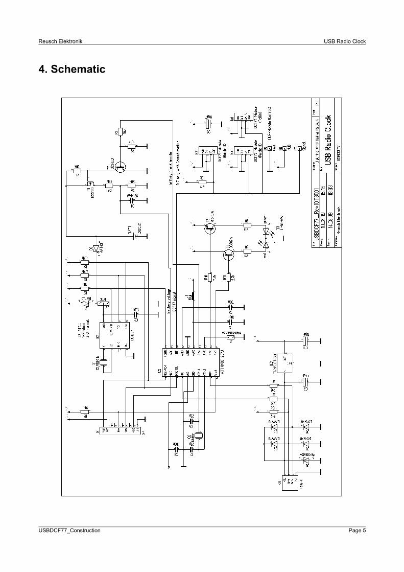
4. Schematic
USBDCF77_Construction Page 5

Reusch Elektronik USB Radio Clock
5. Parts Placement
The following picture shows, how your assembled board should look like (with Reichelt module).
Important hint for board revision 1.0:Please place transistor T1 turned with an angle of 180°, as shown in the picture right! The placement of T1, shown in the pictures above, is wrong!
USBDCF77_Construction Page 6

Reusch Elektronik USB Radio Clock
6. DCF Module PlacementThe board is prepared to mount three types of DCF modules. Of course: only one module can be assembled!
Reichelt ModuleFor this module the connectors K2 and K4 are reserved. Use K4 for direct mounting with four short pieces of wire. K2 is designed to use a 4 pin connector (as shown in the picture). Mount the module that the parts side is the upper side. R17 will be omitted.
Conrad ModuleFor this module the connector pins K5 (Gnd), K6 (+UB) and K7 (non inverted Signal) are reserved. Use three short copper wires (0.8mm) to connect the module. The board has two 2.5mm holes to mount the module with two screws. This module type has an open collector output, so R17 has to be assembled (missing in the picture).
Pollin ModuleFor this module type connector K6 is reserved. An angled four pin female connector can be used, as shown in the picture. Note, that this module has another pin assignment as the Reichelt module! R17 will be omitted.
USBDCF77_Construction Page 7

Reusch Elektronik USB Radio Clock
Other modulesFor other modules (see 2.) one of the upper described connectors has to be used. Choose the best fitting and suitable.
7. Design VariationsThe USB Radio Clock design allows three variations of equipment. If you don't need all features (e.g. the real time clock), you can omit all devices, required for this functionality. See also parts list (2.2), column “option”. The following design variations are possible:
7.1 Full EquipmentIn this design the full functionality is given. That means:
• DCF time module
• battery buffered backup real time clock
• ability, to measure battery voltage
For this design option all parts has to be assembled on the PCB (only R17 depends on chosen DCF module).
7.2 No Battery Voltage MeasureIn this design option it will be abandoned for the ability to measure the battery voltage. In this option all parts, characterised as “Option B” can be omitted.
7.3 No Real Time ClockIn this design option there will be abandoned for the real time clock. That means, that no valid time is available at power up (at least one full minute has to be waiting for, until radio clock time is available). If you abandon this feature, it is not necessary to measure the battery voltage! In this option all parts, characterised as “Option A” and “Option B” can be omitted.
Note:When the gadget is finished, use the USB Radio Clock Serialization Software, to configure the device, depending on the equipment.
USBDCF77_Construction Page 8

Reusch Elektronik USB Radio Clock
8. Starting UpBefore You connect to power, please check for the correct equipment (especially the electrolytic capacitors) and for perfect solders.
For start up don't use an USB plug, which is directly from the root hub. To prevent damages of the computer main board, use an USB hub!
8.1 First Test and StartupFor a first test you can leave out IC1, IC2 and the DCF module (if a disconnectable line is used). Also the battery can leaved out. Now execute the following steps:
1. Connect the USB cable.
2. Measure internal supply voltage (Pin 8 of IC1 or Pin5 of IC2). It should have a value about 3.3 Volts.
3. The LED should be off.
4. Current consumption should be only a few milliamperes.
5. If Your running “Windows” wants to install driver files for a new found device, please cancel.
6. Unplug the USB cable.
8.2 Final Test and InstallationFor the final test all necessary parts (IC1, IC2 and DCF module) are set on the PCB. Please install the Windows software package before testing (so the required driver files are available).
1. If the real time clock is equipped, a few less voltage as the battery voltage should be measured at pin 8 of IC1 (more than 3 Volts with a fresh battery). Note, that a jumper has to be placed on J2, between pins 2 and 3.
2. Connect the USB cable
3. Your running “Windows” should view the dialogue for a new found device. Ignore it in this moment, but don't cancel!
4. The LED should light, or flash if a DCF77 radio signal is receiving.
5. If available, start the “Windows” application USBView. An USB device named “USB DCF77 Clock” should be found in the list of devices.
6. Now install the device in “Windows” (driver files). That means: continue the shown dialogue. Take the path, which were be chosen at software package installation, as the path with the driver files (manual selection of driver file path).
7. Execute the USB Radio Clock Serialization Tool. Open the device (usually with the serial number “00000000”). Set up the equipment and choose a new serial number.
8. Replug the gadget. The driver installation dialogue will be prompted again, when you have set a new serial number. Now You can choose the automatic driver installation (the necessary driver files are copied into the “Windows” directory in the step before).
USBDCF77_Construction Page 9

Reusch Elektronik USB Radio Clock
Now the gadget is ready to use with the main application (USB Radio Clock TNA Application).
9. LinksVisit the following links for more information and download about this product, used software modules and tools.
Reusch Elektronik electronic product home:http://products.reworld.eu
V-USB, Virtual USB Port for AVR microcontroller:http://www.obdev.at/products/vusb/index.html
WinAVR, GCC development environment:http://winavr.sourceforge.net/
LibUSB-Win32, USB drivers for Microsoft Windows ®:http://libusb-win32.sourceforge.net/
10. Statement and DisclaimerThis electronic device is designed under best known engineering guidelines. It confirms the appropriate design rules, when proper assembled. No warranty or liability is given for adherence, assured properties, or damages which might be caused by the usage of this hardware or the accessory software.
Please note, Reusch Elektronik doesn't liable for any damages, which will stay in context with this gadget! You assemble, start up and use your gadget at your own risk! If You don't have the qualification to assemble electronic devices, please contact somebody, who is able to do this in a professional way! Reusch Elektronik offers also assembled and ready to run gadgets with warranty (see homepage).
USBDCF77_Construction Page 10