Embed Size (px)
Citation preview
Product # UPS-1500 3-Phase Phone 1-888-567-9596 www.synqor.com Doc.# 005-0006710 Rev. A 08/01/2018 Page 1
UPS
UPS-1500-S-1U-TUPS-1500-E-2U-T
SynQor’s Military-Grade Uninterruptible Power Supply units are designed for the extreme environmental and demanding electrical conditions of Military/Aerospace applications. SynQor’s UPS incorporates field proven high efficiency designs and rugged packaging technologies. This UPS will accept a wide range of input voltage and frequency values while delivering a well-conditioned AC output to the load. Up to three units can be combined to provide higher power, higher voltage and/or multiple output phases. The use of lithium polymer batteries permits the lowest profile and lowest weight solution in its power class. It is designed and manufactured in SynQor’s USA facilities to comply with a wide range of military standards. Options include a 500 W or single 1250 W DC output, a DC input rated for military 28 VDC sources, and an electronic breaker on the AC output provides fault-tolerant parallel operation for higher power and/or N+M redundancy.
Combine units for Higher Power, Voltage, 3-Phase AC output, and/or Redundancy
ContentsTechnical Specification . . . . . . . . . . . . . . . . . . . . . . . . . . . . . . . . 2Application Section . . . . . . . . . . . . . . . . . . . . . . . . . . . . . . . . . . . 5Mechanical Diagrams . . . . . . . . . . . . . . . . . . . . . . . . . . . . . . . . . 9Ordering Information . . . . . . . . . . . . . . . . . . . . . . . . . . . . . . . . 12
Military-Grade UninterrUptible power SUpply
DesigneD & ManufactureD in usa
1500VA/ 1250W Output Power
115 VL-N / 200 VL-L 45-800Hz
3-Phase Delta AC Input Voltage
115Vrms or 230Vrms 50Hz, 60Hz or 400Hz
AC Output Voltage Options
28 Vnom DC Input Voltage Option
500W or 1250W DC Output
Voltage Option
>10 Min. - 1U >24 Min. - 2U Battery Run Time Options
Sealed Construction, Ultra Low Weight, Compact Size
Features• Sealed, weather-proof, shock-proof construction• Hot swappable internal battery pack (lithium polymer)• >10 minute run-time at full power• 1250W (1500VA) output power• Full power operation: -20°C to +55°C• 3 Phase AC input: 85 - 140Vrms L-N (147-242Vrms L-L)• Wide range AC input frequency: 45-800Hz• Power factor correction at AC input• Dual input (AC and optional DC)• True on-line double conversion• Cold start with no AC or DC input connections• Pure sinusoidal AC output voltage (115VAC, 60Hz)• Handles 0.0—1.0 power factor loads and non-linear loads• Up to 3 units can be combined for higher power, voltage or a 3-Phase AC output• Up to 32 units can be combined to form a higher power fault-tolerant, glitch-free system, perhaps with N+M redundancy, by ordering with the "AC Output Electronic Breaker" option and the appropriate configuration cable• User I/O and Configuration signal ports• 1U high rack mount unit (17.00”W x 22.53”D x 1.73"H)
Options• DC input (28Vnom) for dual source• 2U Extended battery pack gives >24 minutes of run-time• 115Vrms or 230Vrms AC output• 50Hz, 60Hz, or 400Hz output• DC1: Auxiliary isolated DC output (up to 500W) • DC2: High power DC output (up to 1250W) parallelable for higher power• Shipboard version with floating neutral wire
Specification Compliance UPS-1500 units are designed to meet:• MIL-STD-1399-300B - Interface Std for Shipboard Systems• MIL-STD-810G - Environmental Engineering Considerations• MIL-STD-461F - Electromagnetic Interference• MIL-STD-704F - Aircraft Electrical Power Characteristics• MIL-STD-1275D - Vehicle Electrical Power Characteristics
N+M REDUNDANCY(optional)
Product # UPS-1500 3-Phase Phone 1-888-567-9596 www.synqor.com Doc.# 005-0006710 Rev. A 08/01/2018 Page 2
UPS
UPS-1500-S-1U-TUPS-1500-E-2U-T
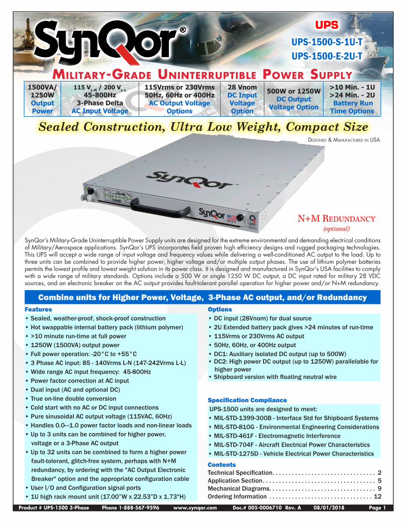
INPUT CHARACTERISTICS Operating AC Input Voltage 85 - 140 Vrms L-N*
147-242 Vrms L-L 3-Phase Connection Type 3-Wire Delta Frequency 45-800 Hz Input Power Factor 0.999 at 45-65Hz
0.98 at 400Hz Maximum Input Current Continuous 8.3A (full load, 85Vrms L-N)
AC Input Circuit Breaker Rating 10A (* Power Derating to 85% below 100 Vrms L-N)
Operating DC Input (Optional) Voltage 22-33V Continuous Maximum Input Current 62A (full load, 22V)
Transient Maximum Input Current 75A
OUTPUT CHARACTERISTICS Total Output Power Continuous 1250W (1500VA) Maximum DC1 Output Power 510W Maximum DC2 Output Power 1250W (Note: Available AC power is reduced by power delivered to the DC output)
AC Output AC Output Waveform Pure Sinusoidal Voltage 115Vrms ± 3%
230Vrms ± 3% Frequency 60Hz ± 0.5%
50Hz ± 0.5%400Hz ± 0.5%
Peak Load Current 26A (115Vrms)13A (230Vrms)
Load Power Factor 0-1.0 (leading or lagging)
Total Harmonic Distortion 2% (1000W resistive load)
DC1 Output (optional) Voltage Regulation (Over Load & Temperature) ± 3% Common Voltage/Power combinations (DC1) 12V at 42A =504W (Other Options Available) 15V at 34A =510W
24V at 21A =504W28V at 18A =504W40V at 12.5A =500W50V at 10A =500W
DC2 Output (optional) Voltage Setpoint ± 3% No Sharing Voltage Regulation (Over Load & Temperature) -2% Common Voltage/Power combinations (DC2) 24V at 50A =1200W
28V at 44.6A =1250W50 V at 20 A =1000W
Droop Share (Output droops vs. load to allow passive sharing among modules.)
24V Option Voltage Regulation (Over Load & Temperature) -15%
26V at 0A22V at 50A =1100W
28V Option Voltage Regulation (Over Load & Temperature) -13%
30V at 0A26V at 48.1A =1250W
ENVIRONMENTAL CHARACTERISTICS MIL-STD-810G Temperature Methods 501.5, 502.5 Operating Temperature -20°C — +55°C Storage Temperature -40°C — +65°C Altitude Method 500.5 Operating 0 - 18,000 ft Non-operating 0 - 40,000 ft Environmental Tests Shock/Drop Method 516.6, Procedures 1,4,6 Temperature Shock Method 503.5, Procedure 1 Vibration Method 514.6, CAT 5, 7, 8, 9, 24 Fungus Method 508.6 Salt Fog Method 509.5 Sand and Dust Method 510.5, Procedures 1,2 Rain Method 506.5, Procedure 1 Humidity Method 507.5, Procedure 2 Mechanical Vibrations of Method 528, Procedure 1 Shipboard Equipment
RELIABILITY CHARACTERISTICS MIL-HDBK-217F MTBF 100 kHrs MIL-217F Ground Benign, Ta=25 °C
ELECTROMAGNETIC CAPABILITY MIL-STD-461F CE101 30 Hz - 10 kHz CE102 10 kHz - 10 MHz CS101 30 Hz - 150 kHz CS106 10 kHz - 40 GHz CS114 10 kHz - 200 MHz CS116 10 kHz - 100 MHz RE101 30 Hz - 100 kHz RE102 10 kHz - 18 GHz RS101 30 Hz - 100 kHz RS103 2 MHz - 40 GHz
MECHANICAL CHARACTERISTICS 1U (Standard Battery Pack) Chassis Size (H x W x D) 17.00"W x 22.53"D x 1.73"(1U) Case Material Aluminum Total Weight 32 lbs. (with chassis & battery) 2U (Extended Battery Pack) Chassis Size (H x W x D) 17.00"W x 22.53"D x 3.33"(2U) Case Material Aluminum Total Weight 50 lbs. (with chassis & battery) Connectors AC Input Connector MS3470L14-4PW DC Input Connector MS3470L18-8P AC Output Connector MS3470L14-4S DC1 Output Connector MS3470L14-4SW DC2 Output Connector MS3470L18-8S User I/O Ports HD DB15 Female Configuration I/O Port HD DB15 Male Ethernet Port Amphenol RJF22N00, Code B Cooling Exhaust Fans Sound Pressure Level (SPL) 54 dB(A) Air Flow 0.67(m3/min) 23.7 CFM
Two fans in system, above specs are for each fan separately.
Technical Specification
Product # UPS-1500 3-Phase Phone 1-888-567-9596 www.synqor.com Doc.# 005-0006710 Rev. A 08/01/2018 Page 3
UPS
UPS-1500-S-1U-TUPS-1500-E-2U-T
Technical Specification
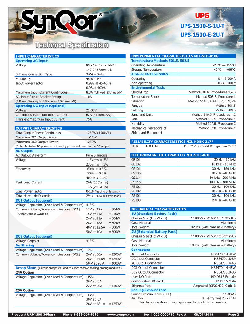
LITHIUM-POLYMER BATTERY CHARACTERISTICS
Standard 1U Battery Pack Run Time1250W : 10 min 1000W : 13 min 625W : 21 min
Optional 2U Extended Battery Pack Run Time1250W : 24 min 1000W : 31 min 625W : 50 min
Recharge Time (to 90% charge) Standard Total Output Power < 1000W 2 hrs Optional 2U Extended Battery Pack Total Output Power < 1000W 4 hrsTemperature Range for Recharge: 0°C to 45°CInternal heaters maintain battery temperature above 0°C when input power is present.Battery charging only enabled below +45°C.
High Density DB15 Female (15 Pin Connector)Signal PIN Function
TX 2 RS232 DCE Device TransmitRX 3 RS232 DCE Device Receive
GND 4, 5 Ground reference for all digital inputs and outputs
LOW_BATT 6 Open collector output where “low” indicates battery charge level <10%
ACIN_GOOD 7 Open collector output where “low” indicates AC Input voltage is within range
+5V 8 Vout with minimal current drive usable as a pull-up voltage for open collector output signals. Load must be <35mA
ON_BATT 9 Open collector output where “low” indicates that the UPS is running on battery power.
REMOTE_START 12 Drive this line “high” with ≥5mA to enable UPS outputs
SHUTDOWN 13 Drive this line “high” with ≥5mA to disable UPS outputs
OUT_OK 14 Open collector output where “low” indicates AC Output voltage is within range
OVER_TEMP 15 Open collector output where “low” indicates that the UPS is at or above its maximum temperature
Product # UPS-1500 3-Phase Phone 1-888-567-9596 www.synqor.com Doc.# 005-0006710 Rev. A 08/01/2018 Page 4
UPS
UPS-1500-S-1U-TUPS-1500-E-2U-T
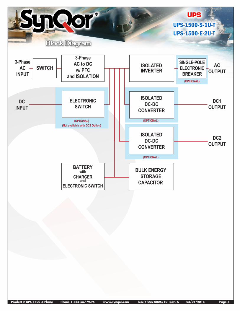
3-PhaseAC
INPUT
DCINPUT
DC2OUTPUT
DC1OUTPUT
ACOUTPUT
3-PhaseAC to DCw/ PFC
and ISOLATION
BATTERYwith
CHARGERand
ELECTRONIC SWITCH
(OPTIONAL)(Not available with DC2 Option)
ELECTRONICSWITCH
ISOLATEDINVERTER
BULK ENERGYSTORAGE
CAPACITOR
ISOLATEDDC-DC
CONVERTER
(OPTIONAL)
(OPTIONAL)
(OPTIONAL)
ISOLATEDDC-DC
CONVERTER
SWITCHSINGLE-POLEELECTRONIC
BREAKER
Block Diagram
Product # UPS-1500 3-Phase Phone 1-888-567-9596 www.synqor.com Doc.# 005-0006710 Rev. A 08/01/2018 Page 5
UPS
UPS-1500-S-1U-TUPS-1500-E-2U-T
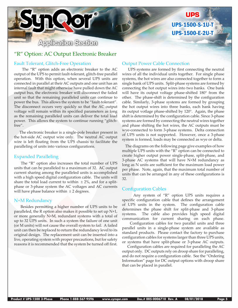
Application Section“R” Option: AC Output Electronic Breaker
Fault Tolerant, Glitch-Free Operation The “R” option adds an electronic breaker to the AC output of the UPS to permit fault-tolerant, glitch-free parallel operation. With this option, when several UPS units are connected in parallel at their AC outputs and one unit has an internal fault that might otherwise have pulled down the AC output bus, the electronic breaker will disconnect the failed unit so that the remaining paralleled units can continue to power the bus. This allows the system to be “fault-tolerant”. The disconnect occurs very quickly so that the AC output voltage will remain within its specified parameters as long as the remaining paralleled units can deliver the total load power. This allows the system to continue running “glitch-free”.
The electronic breaker is a single-pole breaker present in the hot-side AC output wire only. The neutral AC output wire is left floating from the UPS chassis to facilitate the paralleling of units into various configurations.
Expanded Paralleling The “R” option also increases the total number of UPS units that can be paralleled to a maximum of 32. AC output current sharing among the paralleled units is accomplished with a high speed digital configuration cable. The units will share the total load current to within ± 2%, and for a split-phase or 3-phase system the AC voltages and AC currents will have phase balance within ± 2 degrees.
N+M Redundancy Besides permitting a higher number of UPS units to be paralleled, the R option also makes it possible to set up N+1, or more generally N+M, redundant systems with a total of up to 32 UPS units. In such a system the failure of one unit (or M units) will not cause the overall system to fail. A failed unit can then be replaced to return the redundancy level to its original design. The replacement unit can be inserted into a live, operating system with proper precautions, but for safety reasons it is recommended that the system be turned off first.
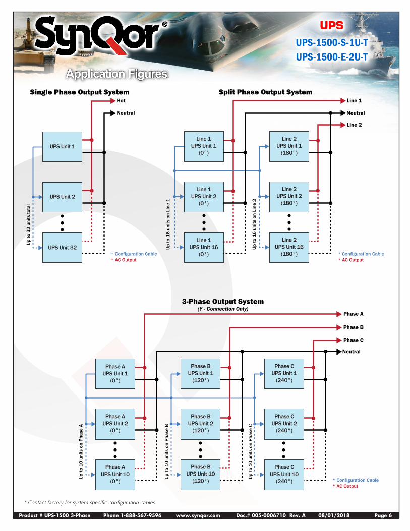
Output Power Cable Connection UPS systems are formed by first connecting the neutral wires of all the individual units together. For single phase systems, the hot wires are also connected together to form a single bank of UPS units. Split-phase systems are formed by connecting the hot output wires into two banks. One bank will have its output voltage phase-shifted 180° from the other. The phase-shift is determined by the configuration cable. Similarly, 3-phase systems are formed by grouping the hot output wires into three banks, each bank having its output votlage phase-shifted by 120°. Again, the phase shift is determined by the configuration cable. Since 3-phase systems are formed by connecting the neutral wires together and phase shifting the hot wires, the AC outputs must be wye-connected to form 3-phase systems. Delta connection of UPS units is not supported. However, once a 3-phase system is formed, loads may be connected as wye or delta.
The diagrams on the following page give examples of how multiple UPS units with the “R” option can be connected to create higher output power single-phase, split-phase, and 3-phase AC systems that will have N+M redundancy as long as N units are sufficient for the maximum load power per phase. Note, again, that the maximum total number of units that can be arranged in any of these configurations is 32.
Configuration Cables Any system of “R” option UPS units requires a specific configuration cable that defines the arrangement of UPS units in the system. The configuration cable determines the phase shift for split-phase and 3-phase systems. The cable also provides high speed digital communication for current sharing on each phase. Configuration cables for two parallel units and three parallel units in a single-phase system are available as standard products. Please contact the factory to purchase configuration cables for systems larger than three UPS units, or systems that have split-phase or 3-phase AC outputs. Configuration cables are required for paralleling the AC output only. DC outputs rely on droop share for paralleling, and do not require a configuration cable. See the “Ordering Information” page for DC output options with droop share that can be placed in parallel.
Product # UPS-1500 3-Phase Phone 1-888-567-9596 www.synqor.com Doc.# 005-0006710 Rev. A 08/01/2018 Page 6
UPS
UPS-1500-S-1U-TUPS-1500-E-2U-T
Application Figures
* Contact factory for system specific configuration cables.
Line 1UPS Unit 1
(0°)
Line 2UPS Unit 1
(180°)
Line 1UPS Unit 2
(0°)
Line 2UPS Unit 2
(180°)
Line 1UPS Unit 16
(0°)
Line 2UPS Unit 16
(180°)
Split Phase Output SystemLine 1
Neutral
Up to
16
units
on
Line
1
Up to
16
units
on
Line
2* Configuration Cable* AC Output
UPS Unit 1
UPS Unit 2
UPS Unit 32
Single Phase Output SystemHot
Up to
32
units
tota
l
* Configuration Cable* AC Output
Neutral
Line 2
Phase AUPS Unit 1
(0°)
Phase BUPS Unit 1
(120°)
Phase AUPS Unit 2
(0°)
Phase BUPS Unit 2
(120°)
Phase AUPS Unit 10
(0°)
Phase BUPS Unit 10
(120°)
3-Phase Output System(Y - Connection Only)
Phase A
Phase B
Phase C
Neutral
Up to
10
units
on
Phas
e A
Up to
10
units
on
Phas
e B
Up to
10
units
on
Phas
e C
* Configuration Cable* AC Output
Phase CUPS Unit 1
(240°)
Phase CUPS Unit 2
(240°)
Phase CUPS Unit 10
(240°)
Product # UPS-1500 3-Phase Phone 1-888-567-9596 www.synqor.com Doc.# 005-0006710 Rev. A 08/01/2018 Page 7
UPS
UPS-1500-S-1U-TUPS-1500-E-2U-T
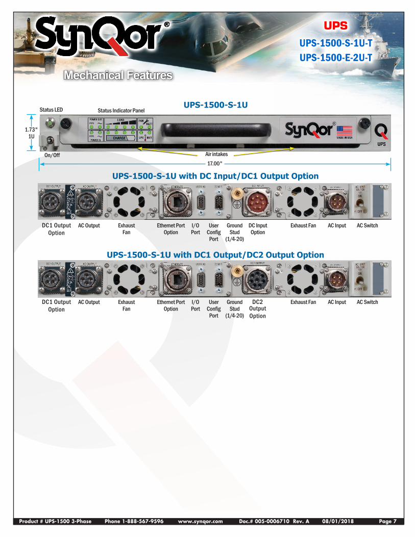
Mechanical Features
DC1 OutputOption
DC1 OutputOption
UPS-1500-S-1U with DC1 Output/DC2 Output Option
Ethernet Port Option
Ethernet Port Option
AC Output
AC Output
Exhaust Fan
Exhaust Fan
Exhaust Fan
Exhaust Fan
I/O Port
I/O Port
User Config
Port
User Config
Port
Ground Stud
(1/4-20)
Ground Stud
(1/4-20)
DC Input Option
AC Input
AC Input
AC Switch
AC Switch
UPS-1500-S-1U with DC Input/DC1 Output Option
Air intakes
Status Indicator PanelStatus LED
On/Off17.00"
1.73" 1U
UPS-1500-S-1U
DC2 OutputOption
Product # UPS-1500 3-Phase Phone 1-888-567-9596 www.synqor.com Doc.# 005-0006710 Rev. A 08/01/2018 Page 8
UPS
UPS-1500-S-1U-TUPS-1500-E-2U-T
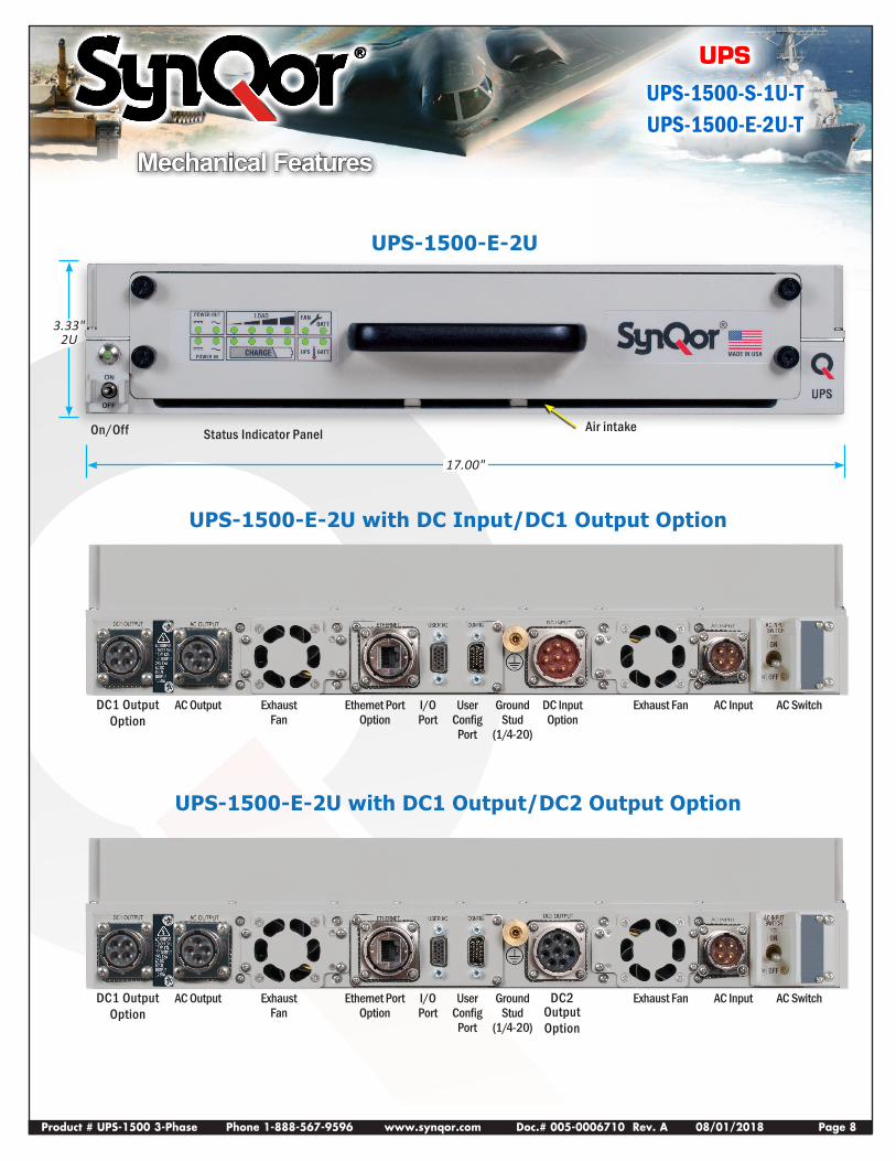
Mechanical Features
Air intakeStatus Indicator Panel
UPS-1500-E-2U
UPS-1500-E-2U with DC Input/DC1 Output Option
UPS-1500-E-2U with DC1 Output/DC2 Output Option
17.00"
3.33" 2U
On/Off
DC1 OutputOption
DC1 OutputOption
Ethernet Port Option
Ethernet Port Option
AC Output
AC Output
Exhaust Fan
Exhaust Fan
Exhaust Fan
Exhaust Fan
I/O Port
I/O Port
User Config
Port
User Config
Port
Ground Stud
(1/4-20)
Ground Stud
(1/4-20)
DC Input Option
AC Input
AC Input
AC Switch
AC SwitchDC2 OutputOption
Product # UPS-1500 3-Phase Phone 1-888-567-9596 www.synqor.com Doc.# 005-0006710 Rev. A 08/01/2018 Page 9
UPS
UPS-1500-S-1U-TUPS-1500-E-2U-T
MADE IN USA
UPS
POWER OUT
POWER IN
LOAD
CHARGE
FANBATT
BATTUPSON
OFF
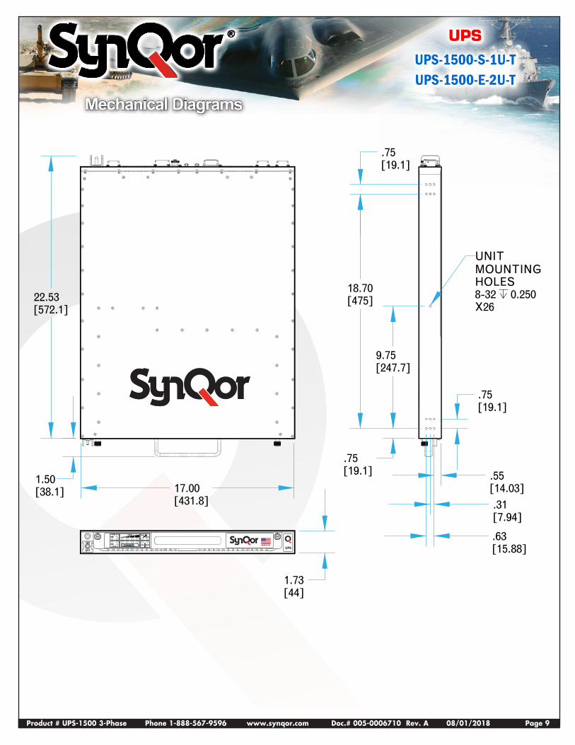
MOUNTINGUNIT
HOLES8-32 0.250X26
.55[14.03].31[7.94]
.63[15.88]
.75[19.1]
1.73[44]
.75[19.1]
1.50[38.1] 17.00
[431.8]
22.53[572.1]
9.75[247.7]
18.70[475]
.75[19.1]
Mechanical Diagrams
Product # UPS-1500 3-Phase Phone 1-888-567-9596 www.synqor.com Doc.# 005-0006710 Rev. A 08/01/2018 Page 10
UPS
UPS-1500-S-1U-TUPS-1500-E-2U-T
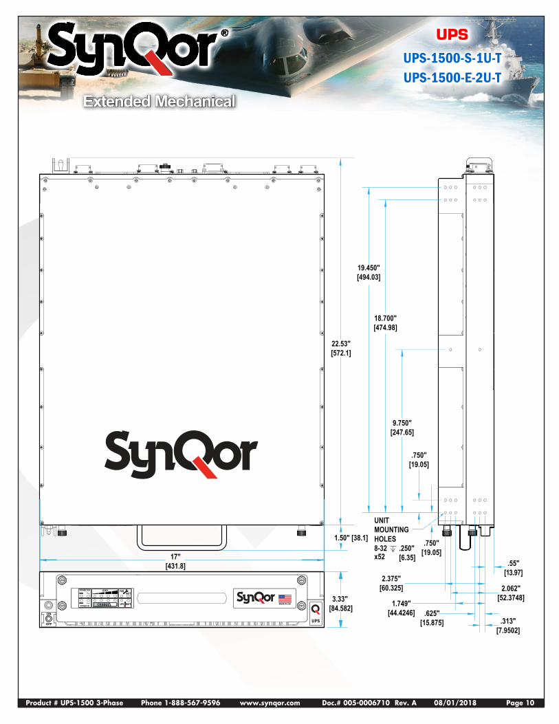
Extended Mechanical
MADE IN USA
UPS
POWER OUT
POWER IN
LOAD
CHARGE
FANBATT
BATTUPS
ON
OFF
3.33" [84.582] 1.749"
[44.4246]
2.062"[52.3748]
2.375"[60.325]
.750"[19.05]
.750"[19.05]
9.750"[247.65]
22.53"[572.1]
18.700"[474.98]
19.450"[494.03]
UNITMOUNTINGHOLES8-32 .250"
[6.35]x52
.313"[7.9502]
.625"[15.875]
.55"[13.97]
1.50" [38.1]
17"[431.8]
Product # UPS-1500 3-Phase Phone 1-888-567-9596 www.synqor.com Doc.# 005-0006710 Rev. A 08/01/2018 Page 11
UPS
UPS-1500-S-1U-TUPS-1500-E-2U-T
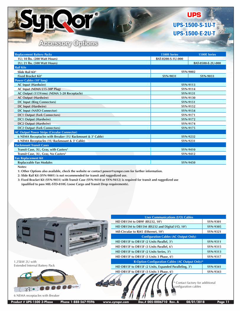
Accessory Options Replacement Battery Packs 1500S Series 1500E Series
1U; 10 lbs. (200 Watt Hours) BAT-0200-S-1U-0002U; 21 lbs. (500 Watt Hours) BAT-0500-E-2U-000
Rail KitsSlide Rail Kit2 SYN-9002Fixed Bracket Kit3 SYN-9031 SYN-9033
Power Cables (10' long)AC Input (Hardwire) SYN-9113AC Input (NEMA L15-30P Plug) SYN-9114AC Output (115Vrms) (NEMA 5-20 Receptacle) SYN-9131AC Output (Hardwire) SYN-9130DC Input (Ring Connectors) SYN-9151DC Input (Hardwire) SYN-9152DC Input (NATO Connector) SYN-9154DC1 Output (Fork Connectors) SYN-9171DC1 Output (Hardwire) SYN-9172DC2 Output (Hardwire) SYN-9174DC2 Output (Fork Connectors) SYN-9175
AC Output Power Strips (Circular Connector)6 NEMA Receptacles with Breaker (1U Rackmount & 3' Cable) SYN-92326 NEMA Receptacles (1U Rackmount & 3' Cable) SYN-9231
Rackmount Transit CasesTransit Case, 3U, Gray, with Casters3 SYN-9410Transit Case, 3U, Gray, No Casters3 SYN-9412
Fan Replacement KitReplaceable Fan Modules SYN-9450Notes:1: Other Options also available, check the website or contact [email protected] for further information. 2: Slide Rail Kit (SYN-9001) is not recommended for transit and ruggedized use.3: Fixed Bracket Kit (SYN-9031) with Transit Case (SYN-9410 or SYN-9412) is required for transit and ruggedized use
(qualified to pass MIL-STD-810G Loose Cargo and Transit Drop requirements).
User Communications (I/O) Cables HD DB15M to DB9F (RS232, 10') SYN-9301
HD DB15M to DB15M (RS232 and Digital I/O, 10') SYN-9305
Mil-Circular to RJ45 (Ethernet, 10') SYN-9321
Configuration Cables (AC Output Only)
HD DB15F to DB15F (2 Units Parallel, 3') SYN-9311
HD DB15F to DB15F (3 Units Parallel, 6') SYN-9315
HD DB15F to DB15F (2 Units Series, 3') SYN-9313
HD DB15F to DB15F (3 Units 3 Phase, 6') SYN-9317
R-Option Configuration Cables (AC Output Only)*
HD DB15F to DB15F (2 Units, Expanded Paralleling, 3') SYN-9341
HD DB15F to DB15F (3 Units 3 Phase, 6') SYN-9343
1.25kW 2U with Extended Internal Battery Pack
6 NEMA receptacles with Breaker
* Contact factory for additional configuration cables
Product # UPS-1500 3-Phase Phone 1-888-567-9596 www.synqor.com Doc.# 005-0006710 Rev. A 08/01/2018 Page 12
UPS
UPS-1500-S-1U-TUPS-1500-E-2U-T
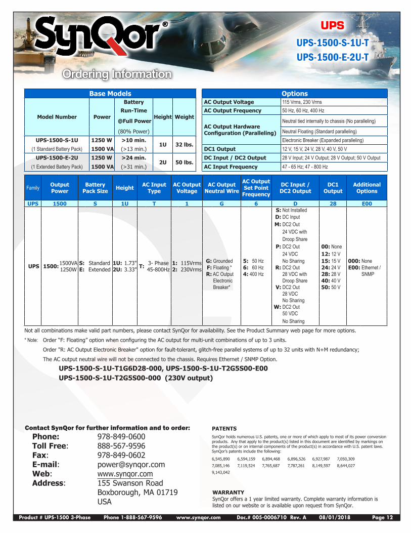
Ordering InformationBase Models Options
Model Number Power
Battery
Height Weight
AC Output Voltage 115 Vrms, 230 VrmsRun-Time AC Output Frequency 50 Hz, 60 Hz, 400 Hz
@Full Power AC Output Hardware Configuration (Paralleling)
Neutral tied internally to chassis (No paralleling)
(80% Power) Neutral Floating (Standard paralleling)UPS-1500-S-1U 1250 W >10 min.
1U 32 lbs. Electronic Breaker (Expanded paralleling)
(1 Standard Battery Pack) 1500 VA (>13 min.) DC1 Output 12 V, 15 V, 24 V, 28 V, 40 V, 50 VUPS-1500-E-2U 1250 W >24 min.
2U 50 lbs. DC Input / DC2 Output 28 V Input; 24 V Output; 28 V Output; 50 V Output
(1 Extended Battery Pack) 1500 VA (>31 min.) AC Input Frequency 47 - 65 Hz; 47 - 800 Hz
Family Output Power
Battery Pack Size Height AC Input
TypeAC Output
VoltageAC Output
Neutral Wire
AC Output Set Point
Frequency
DC Input / DC2 Output
DC1 Output
Additional Options
UPS 1500 S 1U T 1 G 6 D 28 E00
UPS 1500:1500VA 1250W
S: E:
Standard Extended
1U: 2U:
1.73" 3.33" T: 3- Phase
45-800Hz1: 2:
115Vrms 230Vrms
S: Not InstalledD: DC InputM: DC2 Out
24 VDC with Droop Share
P: DC2 Out 00: None 24 VDC 12: 12 V
G: Grounded 5: 50 Hz No Sharing 15: 15 V 000: NoneF: Floating * 6: 60 Hz R: DC2 Out 24: 24 V E00: Ethernet / R: AC Output 4: 400 Hz 28 VDC with 28: 28 V SNMP
Electronic Droop Share 40: 40 V Breaker* V: DC2 Out 50: 50 V
28 VDC No Sharing
W: DC2 Out 50 VDC No Sharing
Not all combinations make valid part numbers, please contact SynQor for availability. See the Product Summary web page for more options.
* Note: Order “F: Floating” option when configuring the AC output for multi-unit combinations of up to 3 units.
Order "R: AC Output Electronic Breaker" option for fault-tolerant, glitch-free parallel systems of up to 32 units with N+M redundancy;
The AC output neutral wire will not be connected to the chassis. Requires Ethernet / SNMP Option.
UPS-1500-S-1U-T1G6D28-000, UPS-1500-S-1U-T2G5S00-E00UPS-1500-S-1U-T2G5S00-000 (230V output)
WARRANTYSynQor offers a 1 year limited warranty. Complete warranty information is listed on our website or is available upon request from SynQor.
Contact SynQor for further information and to order: Phone: 978-849-0600 Toll Free: 888-567-9596 Fax: 978-849-0602 E-mail: [email protected] Web: www.synqor.com Address: 155 Swanson Road Boxborough, MA 01719 USA
PATENTS SynQor holds numerous U.S. patents, one or more of which apply to most of its power conversion products. Any that apply to the product(s) listed in this document are identified by markings on the product(s) or on internal components of the product(s) in accordance with U.S. patent laws. SynQor’s patents include the following:
6,545,890 6,594,159 6,894,468 6,896,526 6,927,987 7,050,309
7,085,146 7,119,524 7,765,687 7,787,261 8,149,597 8,644,027
9,143,042