Embed Size (px)
Citation preview
EN
GLI
SH
9PX 700 RT9PX 1000 RT9PX 1000GRT9PX 1500 RT9PX 1500GRT9PX 2000 RT9PX 2200 GRT9PX 3000 RT9PX 3000 GRT9PX 3000 GLRT9PX EBM 36V RT9PX EBM 48V RT9PX EBM 72V RT
Installation and user manual
Copyright © 2016 EATON All rights reserved.
9PX 1-3 KVA US_EN
Page 2 9PX 1-3 KVA US_EN
SAVE THESE INSTRUCTIONS. This manual contains important instructions that should be followed during installation and maintenance of the UPS and batteries.
The 9PX models that are covered in this manual are intended for installation in an environment within 0 to 40°C, free of conductive contaminant.
This equipment has been tested and found to comply with the limits for a Class A digital device, pursuant to Part 15 of the FCC Rules. These limits are designed to provide reasonable protection against harmful interference when the equipment is operated in a commercial environment. This equipment generates, uses, and can radiate radio frequency energy and, if not installed and used in accordance with the instruction manual, may cause harmful interference to radio communications. Operation of this equipment in a residential area is likely to cause harmful interference in which case the user will be required to correct the interference at his own expense.
Special symbolsThe following are examples of symbols used on the UPS or accessories to alert you to important information:
RISK OF ELECTRIC SHOCK - Observe the warning associated with the risk of electric shock symbol.
Important instructions that must always be followed.
Do not discard the UPS or the UPS batteries in the trash. This product contains sealed lead acid batteries and must be disposed as it's explain in this manual. For more information, contact your local recycling/reuse or hazardous waste center.
This symbol indicates that you should not discard waste electrical or electronic equipment (WEEE) in the trash. For proper disposal, contact your local recycling/reuse or hazardous waste center.
Information, advice, help.
Refer to the user manual of UPS accessories.
SAFETY INSTRUCTIONS
Page 39PX 1-3 KVA US_EN
EN
GLI
SHSAFETY INSTRUCTIONS
Safety of persons• The system has its own power source (the battery). Consequently, the power outlets may be ener-
gized even if the systems is disconnected from the AC power source. Dangerous voltage levels are presentwithinthesystem.Itshouldbeopenedexclusivelybyqualifiedservicepersonnel.
• The system must be properly grounded at all times.
• The battery supplied with the system contains small amounts of toxic materials. To avoid accidents, the directives listed below must be observed:
- Servicing of batteries should be performed or supervised by personnel knowledgeable about bat-teries and the required precautions.
- When replacing batteries, replace with the same type and number of batteries or battery packs.-Donotdisposeofbatteriesinafire.Thebatteriesmayexplode.- Batteries constitute a danger (electrical shock, burns). The short-circuit current may be very high.
• Precautions must be taken for all handling:
- Wear rubber gloves and boots.- Do not lay tools or metal parts on top of batteries. - Disconnect charging source prior to connecting or disconnecting battery terminals.- Determine if battery is inadvertently grounded. If inadvertently grounded, remove source from
ground. Contact with any part of a grounded battery can result in electrical shock. The likelihood of such shock can be reduced if such grounds are removed during installation and maintenance (applicable to equipment and remote battery supplies not having a grounded supply circuit).
Product safety• To connect the UPS, instructions and operation described in the manual must be followed in
the indicated order.
• CAUTION-Toreducetheriskoffire,theunitconnectsonlytoacircuitprovided with 20 or 30 amperes maximum branch circuit overcurrent protection in accordance with the National Electric Code, ANSI/NFPA 70 (US installations only).
• Check that the indications on the rating plate correspond to your AC powered system and to the actual electrical consumption of all the equipment to be connected to the system.
• For PLUGGABLE EQUIPMENT, the socket-outlet shall be installed near the equipment and shall be easily accessible
• Never install the system near liquids or in an excessively damp environment.
• Never let a foreign body penetrate inside the system.
• Never block the ventilation grates of the system.
• Never expose the system to direct sunlight or source of heat.
• If the system must be stored prior to installation, storage must be in a dry place.
• The admissible storage temperature range is -25ºC to +55ºC without batteries, 0°C to 40°C with batteries.
• The system is not for use in a computer room AS DEFINED IN the standard for the Protection of Information Technology Equipment, ANSI/NFPA 75 (US installations only).
Contact Eaton resellers to order a special battery kit, if needed to meet the ANSI/NFPA 75 requirement.

Page 4 9PX 1-3 KVA US_EN
SAFETY INSTRUCTIONS
Special precautions• The unit is heavy: wear safety shoes and use vacuum lifter preferentially for handling operations.
• All handling operations will require at least two people (unpacking, lifting, installation in rack system).
• Before and after the installation, if the UPS remains de-energized for a long period, the UPS must be energized for a period of 24 hours, at least once every 6 months (for a normal storage temperature less than 25°C). This charges the battery, thus avoiding possible irreversible damage.
• During the replacement of the Battery Module, it is imperative to use the same type and number of element as the original Battery Module provided with the UPS to maintain an identical level of performance and safety. If there are any questions, don’t hesitate to contact your EATON representative.
• All repairs and service should be performed by AUTHORIZED SERVICE PERSONNEL ONLY. There are NO USER SERVICEABLE PARTS inside the UPS.
• For potential safety issue on defective UPS : DISCONNECT INTERNAL BATTERY for storage and transportation.
Page 59PX 1-3 KVA US_EN
EN
GLI
SHContents
1. Introduction .........................................................................................1.1 Environmental protection ...............................................................................................6
2. Presentation ........................................................................................2.1 Standard installations .....................................................................................................82.2 Rear panels ....................................................................................................................92.3 Accessories ................................................................................................................. 102.4 Control panel ................................................................................................................ 112.5 LCD description ...........................................................................................................122.6 Display functions .........................................................................................................132.7 User settings ...............................................................................................................13
3. Installation ..........................................................................................3.1 Inspecting the equipment ........................................................................................... 173.2 Checking the accessory kit .......................................................................................... 173.3 Connecting the internal battery ...................................................................................213.4 Connecting the EBM(s) ...............................................................................................223.5 Connecting other accessories ....................................................................................223.6 Tower installation .........................................................................................................233.7 Rack installation ...........................................................................................................243.8 UPS connection without HotSwap MBP module ........................................................253.9 Connection with a HotSwap MBP module (optional accessory) ........................................ 26
4. Communication ..................................................................................4.1 Communication ports ..................................................................................................284.2 UPS remote control functions .....................................................................................294.3 Eaton Intelligent Power Software suite .......................................................................31
5. Operation.............................................................................................5.1 Start-up and Normal operation .....................................................................................325.2 Starting the UPS on Battery .........................................................................................325.3 UPS Shutdown ............................................................................................................325.4 Operating modes .........................................................................................................325.5 Return of AC Input Power ............................................................................................335.6 Setting High Efficiency mode ......................................................................................335.7 Configuring Bypass settings ........................................................................................335.8 Configuring battery settings ........................................................................................345.9 Retrieving the Event log ...............................................................................................345.10 Retrieving the Fault log ................................................................................................34
6. UPS maintenance ...............................................................................6.1 Equipment care ............................................................................................................356.2 Storing the equipment .................................................................................................356.3 When to replace batteries ...........................................................................................356.4 Replacing batteries ......................................................................................................366.5 Replacing the UPS equipped with a HotSwap MBP ....................................................386.6 Recycling the used equipment ....................................................................................38
7. Troubleshooting ...................................................................................7.1 Typical alarms and faults ..............................................................................................397.2 Silencing the alarm ......................................................................................................407.3 Service and support .....................................................................................................407.4 CE compliance contact ................................................................................................40
8. Specifications ......................................................................................8.1 Model specifications ..................................................................................................41
9. Glossary ........................................................................................... 45
Page 6 9PX 1-3 KVA US_EN
1. Introduction
Thank you for selecting an EATON product to protect your electrical equipment. The 9PX range has been designed with the utmost care.We recommend that you take the time to read this manual to take full advantage of the many features of your UPS (Uninterruptible Power System). Before installing your 9PX, please read the booklet presenting the safety instructions. Then follow the indications in this manual. To discover the entire range of EATON products and the options available for the 9PX range, we invite you to visit our web site at www.eaton.com/powerquality or contact your EATON representative.
1.1 Environmental protection
EATON has implemented an environmental-protection policy.Products are developed according to an eco-design approach.
Substances
This product does not contain CFCs, HCFCs or asbestos.
Packing
To improve waste treatment and facilitate recycling, separate the various packing components.• The cardboard we use comprises over 50% of recycled cardboard.
• Sacks and bags are made of polyethylene.
• Packingmaterialsarerecyclableandbeartheappropriateidentificationsymbol 01
PET
Materials Abbreviations Number in 01
PET
the symbols
Polyethylene terephthalat PET 01
High-density polyethylene HDPE 02
Polyvinyl chloride PVC 03
Low-density polyethylene LDPE 04
Polypropylene PP 05
Polystyrene PS 06
Follow all local regulations for the disposal of packing materials.
End of life
EATON will process products at the end of their service life in compliance with local regulations.EATON works with companies in charge of collecting and eliminating our products at the end of their service life.
Product
The product is made up of recyclable materials.Dismantling and destruction must take place in compliance with all local regulations concerning waste.At the end of its service life, the product must be transported to a processing center for electrical and electronic waste.
Battery
The product contains lead-acid batteries that must be processed according to applicable local regulations concerning batteries. The battery may be removed to comply with regulations and in view of correct disposal.
Page 79PX 1-3 KVA US_EN
EN
GLI
SH1. Introduction
The Eaton® 9PX uninterruptible power system (UPS) protects your sensitive electronic equipment from the most common power problems, including power failures, power sags, power surges, brownouts, line noise, high voltage spikes, frequency variations, switching transients, and harmonic distortion.Power outages can occur when you least expect it and power quality can be erratic. These power problems have the potential to corrupt critical data, destroy unsaved work sessions, and damage hardware - causing hours of lost productivity and expensive repairs.With the Eaton 9PX, you can safely eliminate the effects of power disturbances and guard the integrity ofyourequipment.Providingoutstandingperformanceandreliability,theEaton9PX’suniquebenefitsinclude:• True online double-conversion technology with high power density, utility frequency independence, and
generator compatibility.
• ABM® technology that uses advanced battery management to increase battery service life, optimize recharge time, and provide a warning before the end of useful battery life.
• SelectableHighEfficiencymodeofoperation.
• Standard communication options: one RS-232 communication port, one USB communication port, and relay output contacts.
• Optional connectivity cards with enhanced communication capabilities.
• Extended runtime with up to four Extended Battery Modules (EBMs) per UPS.
• Remote On/Off control through Remote On/Off (ROO) and Remote Power Off (RPO) ports.
• Backed by worldwide agency approvals.
Page 8 9PX 1-3 KVA US_EN
2. Presentation
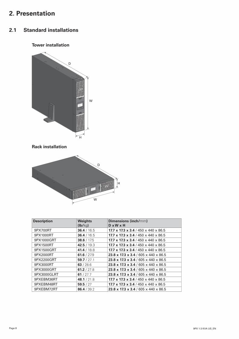
2.1 Standard installations
Tower installation
D
W
H
Rack installation
D
H
W
Description Weights (lb/kg)
Dimensions (inch/mm) D x W x H
9PX700RT 36.4 / 16.5 17.7 x 17.3 x 3.4 / 450 x 440 x 86.59PX1000RT 36.4 / 16.5 17.7 x 17.3 x 3.4 / 450 x 440 x 86.59PX1000GRT 38.6 / 17.5 17.7 x 17.3 x 3.4 / 450 x 440 x 86.59PX1500RT 42.5 / 19.3 17.7 x 17.3 x 3.4 / 450 x 440 x 86.59PX1500GRT 41.4 / 18.8 17.7 x 17.3 x 3.4 / 450 x 440 x 86.59PX2000RT 61.6 / 27.9 23.8 x 17.3 x 3.4 / 605 x 440 x 86.59PX2200GRT 59.7 / 27.1 23.8 x 17.3 x 3.4 / 605 x 440 x 86.59PX3000RT 63 / 28.6 23.8 x 17.3 x 3.4 / 605 x 440 x 86.59PX3000GRT 61.2 / 27.8 23.8 x 17.3 x 3.4 / 605 x 440 x 86.59PX3000GLRT 61 / 27.7 23.8 x 17.3 x 3.4 / 605 x 440 x 86.59PXEBM36RT 48.1 / 21.8 17.7 x 17.3 x 3.4 / 450 x 440 x 86.59PXEBM48RT 59.5 / 27 17.7 x 17.3 x 3.4 / 450 x 440 x 86.59PXEBM72RT 86.4 / 39.2 23.8 x 17.3 x 3.4 / 605 x 440 x 86.5
Page 99PX 1-3 KVA US_EN
EN
GLI
SH2. Presentation
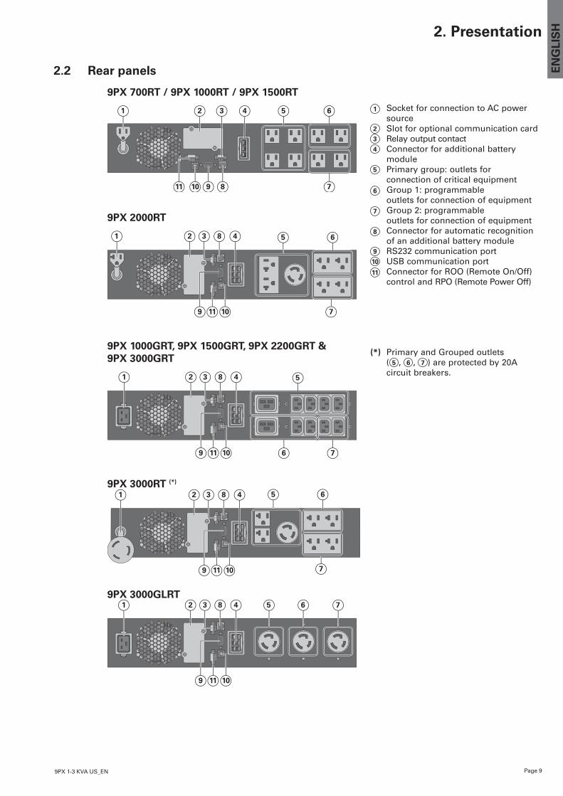
2.2 Rear panels
9PX 700RT / 9PX 1000RT / 9PX 1500RT
1 2 3 4 5 6
9 811 10 7
9PX 2000RT
1 82 43 5 6
9 1011 7
9PX 1000GRT, 9PX 1500GRT, 9PX 2200GRT & 9PX 3000GRT
1 82 43 5
9 1011 6 7
9PX 3000RT (*)
1 82 43 5 6
9 1011 7
9PX 3000GLRT1 82 43 5 6 7
9 1011
1 Socket for connection to AC power source
2 Slot for optional communication card 3 Relay output contact4 Connector for additional battery
module 5 Primary group: outlets for
connection of critical equipment6 Group 1: programmable
outlets for connection of equipment7 Group 2: programmable
outlets for connection of equipment8 Connector for automatic recognition
of an additional battery module9 RS232 communication port10 USB communication port11 Connector for ROO (Remote On/Off)
control and RPO (Remote Power Off)
(*) Primary and Grouped outlets ( 5 , 6 , 7 ) are protected by 20A circuit breakers.
Page 10 9PX 1-3 KVA US_EN
2. Presentation
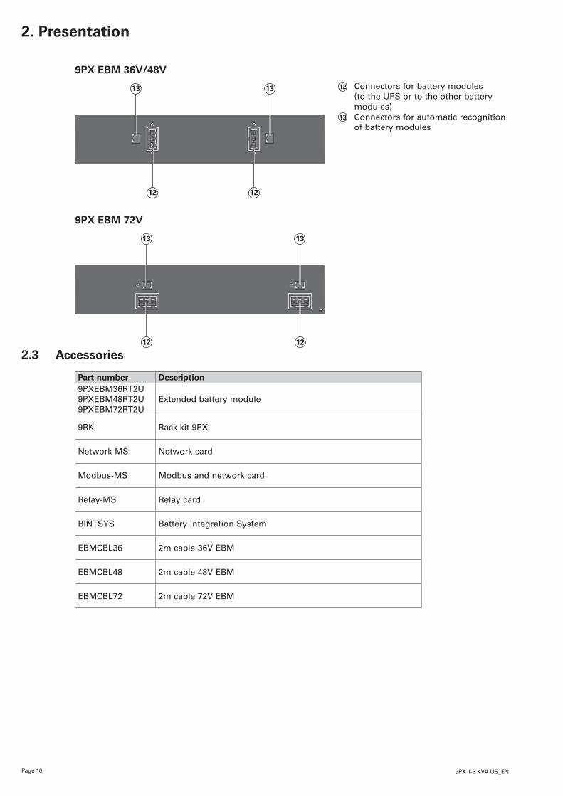
9PX EBM 36V/48V
13 13
1212
12 Connectors for battery modules (to the UPS or to the other battery modules)
13 Connectors for automatic recognition of battery modules
9PX EBM 72V
13 13
1212
2.3 Accessories
Part number Description9PXEBM36RT2U9PXEBM48RT2U9PXEBM72RT2U
Extended battery module
9RK Rack kit 9PX
Network-MS Network card
Modbus-MS Modbus and network card
Relay-MS Relay card
BINTSYS Battery Integration System
EBMCBL36 2m cable 36V EBM
EBMCBL48 2m cable 48V EBM
EBMCBL72 2m cable 72V EBM
Page 119PX 1-3 KVA US_EN
EN
GLI
SH2. Presentation
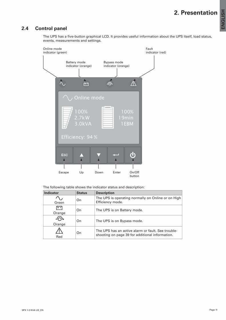
2.4 Control panel
TheUPShasafive-buttongraphicalLCD.ItprovidesusefulinformationabouttheUPSitself,loadstatus,events, measurements and settings.
Online mode indicator (green)
Fault indicator (red)
Online mode
100%19min1EBM
100%2.7kW3.0kVA
Efficiency: 94 %
Escape Up Down Enter On/Off button
Battery mode indicator (orange)
Bypass mode indicator (orange)
The following table shows the indicator status and description:
Indicator Status Description
Green
On The UPS is operating normally on Online or on High Efficiency mode.
Orange
On The UPS is on Battery mode.
OrangeOn The UPS is on Bypass mode.
Red
On The UPS has an active alarm or fault. See trouble-shooting on page 39 for additional information.
Page 12 9PX 1-3 KVA US_EN
2. Presentation
2.5 LCD description
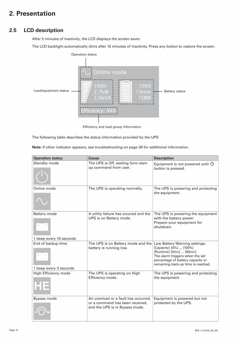
After 5 minutes of inactivity, the LCD displays the screen saver.
The LCD backlight automatically dims after 10 minutes of inactivity. Press any button to restore the screen.
Operation status
Load/equipment status
Online mode
100%19min1EBM
100%2.7kW3.0kVA
Efficiency: 94%
Battery status
Efficiency and load group information
The following table describes the status information provided by the UPS
Note: If other indicator appears, see troubleshooting on page 39 for additional information.
Operation status Cause DescriptionStandby mode The UPS is Off, waiting form start-
up command from user.Equipment is not powered until button is pressed.
Online mode The UPS is operating normally. The UPS is powering and protecting the equipment.
Battery mode
1 beep every 10 seconds
A utility failure has occured and the UPS is on Battery mode.
The UPS is powering the equipment with the battery power.Prepare your equipment for shutdown.
End of backup time
1 beep every 3 seconds
The UPS is on Battery mode and the battery is running low.
Low Battery Warning settings: [Capacity] [0%] ... [100%][Runtime] [0mn] ... [60mn]The alarm triggers when the set percentage of battery capacity or remaining back-up time is reached.
High Efficiency mode The UPS is operating on High Efficiency mode.
The UPS is powering and protecting the equipment
Bypass mode An overload or a fault has occurred, or a command has been received, and the UPS is in Bypass mode.
Equipment is powered but not protected by the UPS.
Page 139PX 1-3 KVA US_EN
EN
GLI
SH
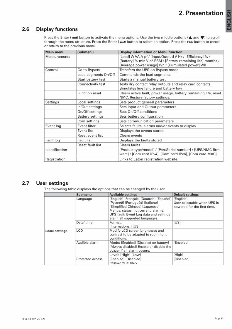
2.6 Display functions
Press the Enter ( ) button to activate the menu options. Use the two middle buttons ( and ) to scroll through the menu structure. Press the Enter ( ) button to select an option. Press the button to cancel or return to the previous menu.
Main menu Submenu Display information or Menu functionMeasurements [Load] W VA A pf / [Input/Output] V Hz / [Efficiency] % /
[Battery] % min V n° EBM / [Battery remaining life] months / [Average power usage] Wh / [Cumulated power] Wh
Control Go to Bypass Transfers the UPS on Bypass modeLoad segments On/Off Commands the load segmentsStart battery test Starts a manual battery testConnectivity test Tests dry contact relay outputs and relay card contacts.
Simulates line failure and battery lowFunction reset Clears active fault, power usage, battery remaining life, reset
NMC, Restore factory settings.Settings Local settings Sets product general parameters
In/Out settings Sets Input and Output parametersOn/Off settings Sets On/Off conditionsBattery settings Sets battery configurationCom settings Sets communication parameters
Event log Event filter Selects faults, alarms and/or events to displayEvent list Displays the events storedReset event list Clears events
Fault log Fault list Displays the faults storedReset fault list Clears faults
Identification [Product type/model] / [Part/Serial number] / [UPS/NMC firm-ware] / [Com card IPv4], [Com card IPv6], [Com card MAC]
Registration Links to Eaton registration website
2.7 User settingsThe following table displays the options that can be changed by the user.
Submenu Available settings Default settings
Local settings
Language [English] [Français] [Deutsch] [Español] [Русский] [Português] [Italiano] [Simplified Chinese] [Japanese] Menus, status, notices and alarms, UPS fault, Event Log data and settings are in all supported languages.
[English] User selectable when UPS is powered for the first time.
Date/ time Format:[International] [US]
[US]
LCD Modify LCD screen brightness and contrast to be adapted to room light conditions.
Audible alarm Mode: [Enabled] [Disabled on battery] [Always disabled] Enable or disable the buzzer if an alarm occurs.
[Enabled]
Level: [High] [Low] [High]Protected access [Enabled] [Disabled]
Password is: 0577[Disabled]
2. Presentation
Page 14 9PX 1-3 KVA US_EN
2. Presentation
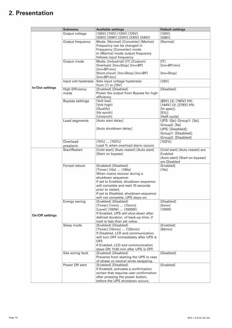
Submenu Available settings Default settings
In/Out settings
Output voltage [100V] [110V] [120V] [125V][200V] [208V] [220V] [230V] [240V]
[120V][208V]
Output frequency Mode: [Normal] [Converter] [Marine]Frequency can be changed in Frequency [Converter] modeIn [Marine] mode output frequency follows input frequency
[Normal]
Output mode Mode: [Industrial] [IT] [Custom]Overload: [Inv>Stop] [Inv>BP] [Inv>BP>Inv]Short-circuit: [Inv>Stop] [Inv>BP] [Inv>BP>Inv]
[IT][Inv>BP>Inv]
[Inv>Stop]
Input volt hysteresis Sets input voltage hysteresisfrom [1] to |10V]
[10V]
High Efficiency mode
[Enabled] [Disabled]Power the output from Bypass for high efficiency
[Disabled]
Bypass settings [Volt low] [Volt high] [Qualify] [Hz synch] [Unsynch]
[80V] LV; [160V] HV;[144V] LV; [276V] HV;[In spec];[5%];[Half cycle]
Load segments [Auto start delay]
[Auto shutdown delay]
UPS: [0s]; Group1: [3s]; Group2: [6s]UPS: [Disabled]; Group1: [Disabled]; Group2: [Disabled]
Overload prealarm
[10%] … [102%]Load % when overload alarm occurs
[102%]
On/Off settings
Start/Restart [Cold start] [Auto restart] [Auto start] [Start on bypass]
[Cold start] [Auto restart] are Enabled[Auto start] [Start on bypass] are Disabled
Forced reboot [Enabled] [Disabled][Timer] [10s] … [180s]When mains recover during a shutdown sequence:If set to Enabled, shutdown sequence will complete and wait 10 seconds prior to restart,If set to Disabled, shutdown sequence will not complete, UPS stays on.
[Enabled][10s]
Energy saving [Enabled] [Disabled][Timer] [1min] … [15min] [Level] [100W] … [1000W]If Enabled, UPS will shut-down after defined duration. of back-up time, if load is less than set value.
[Disabled][5min][100W]
Sleep mode [Enabled] [Disabled][Timer] [10min] … [120min]If Disabled, LCD and communication will turn OFF immediately after UPS is OFF.If Enabled, LCD and communication stays ON 1h30 min after UPS is OFF.
[Enabled][90min]
Site wiring fault [Enabled] [Disabled]Prevents from starting the UPS in case of phase vs neutral wires swapping.
[Disabled]
Power Off alert [Enabled] [Disabled] If Enabled, activates a confirmation screen that requires user confirmation after pressing the power button, before the UPS shutdown occurs.
[Enabled]
Page 159PX 1-3 KVA US_EN
EN
GLI
SH
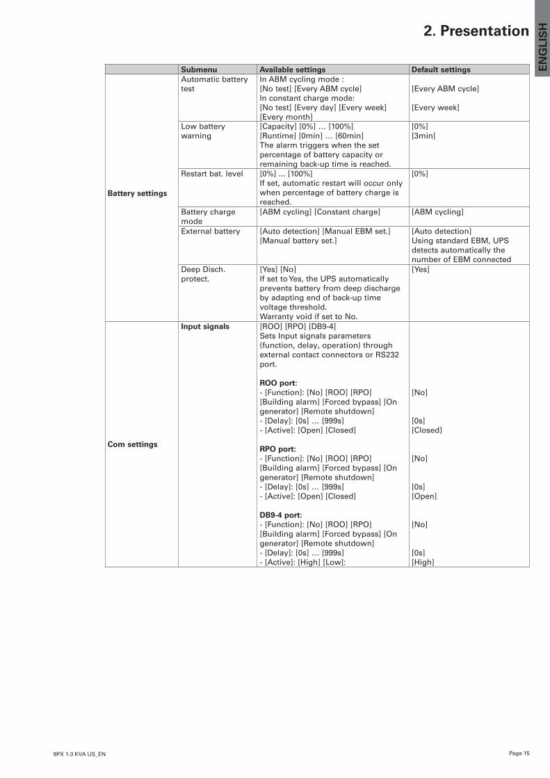
Submenu Available settings Default settings
Battery settings
Automatic battery test
In ABM cycling mode :[No test] [Every ABM cycle]In constant charge mode:[No test] [Every day] [Every week][Every month]
[Every ABM cycle]
[Every week]
Low battery warning
[Capacity] [0%] … [100%][Runtime] [0min] … [60min]The alarm triggers when the set percentage of battery capacity or remaining back-up time is reached.
[0%][3min]
Restart bat. level [0%] ... [100%] If set, automatic restart will occur only when percentage of battery charge is reached.
[0%]
Battery charge mode
[ABM cycling] [Constant charge] [ABM cycling]
External battery [Auto detection] [Manual EBM set.][Manual battery set.]
[Auto detection]Using standard EBM, UPS detects automatically the number of EBM connected
Deep Disch. protect.
[Yes] [No]If set to Yes, the UPS automatically prevents battery from deep discharge by adapting end of back-up time voltage threshold.Warranty void if set to No.
[Yes]
Com settings
Input signals [ROO] [RPO] [DB9-4]Sets Input signals parameters (function, delay, operation) through external contact connectors or RS232 port.
ROO port:- [Function]: [No] [ROO] [RPO] [Building alarm] [Forced bypass] [On generator] [Remote shutdown]- [Delay]: [0s] … [999s]- [Active]: [Open] [Closed]
RPO port:- [Function]: [No] [ROO] [RPO] [Building alarm] [Forced bypass] [On generator] [Remote shutdown]- [Delay]: [0s] … [999s]- [Active]: [Open] [Closed]
DB9-4 port:- [Function]: [No] [ROO] [RPO] [Building alarm] [Forced bypass] [On generator] [Remote shutdown]- [Delay]: [0s] … [999s]- [Active]: [High] [Low]:
[No]
[0s][Closed]
[No]
[0s][Open]
[No]
[0s][High]
2. Presentation
Page 16 9PX 1-3 KVA US_EN
2. Presentation
Submenu Available settings Default settings
Com settings
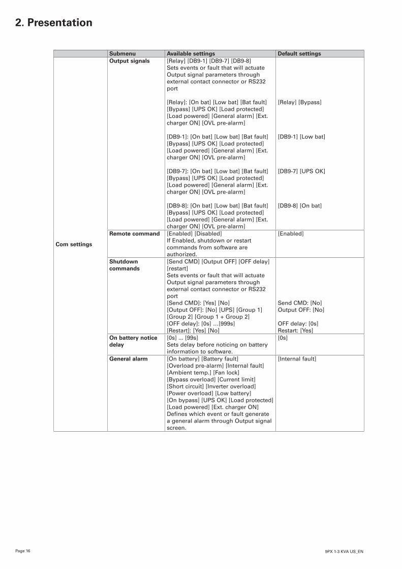
Output signals [Relay] [DB9-1] [DB9-7] [DB9-8]Sets events or fault that will actuate Output signal parameters through external contact connector or RS232 port
[Relay]: [On bat] [Low bat] [Bat fault] [Bypass] [UPS OK] [Load protected] [Load powered] [General alarm] [Ext. charger ON] [OVL pre-alarm]
[DB9-1]: [On bat] [Low bat] [Bat fault] [Bypass] [UPS OK] [Load protected] [Load powered] [General alarm] [Ext. charger ON] [OVL pre-alarm]
[DB9-7]: [On bat] [Low bat] [Bat fault] [Bypass] [UPS OK] [Load protected] [Load powered] [General alarm] [Ext. charger ON] [OVL pre-alarm]
[DB9-8]: [On bat] [Low bat] [Bat fault] [Bypass] [UPS OK] [Load protected] [Load powered] [General alarm] [Ext. charger ON] [OVL pre-alarm]
[Relay] [Bypass] [DB9-1] [Low bat] [DB9-7] [UPS OK] [DB9-8] [On bat]
Remote command [Enabled] [Disabled]If Enabled, shutdown or restart commands from software are authorized.
[Enabled]
Shutdown commands
[Send CMD] [Output OFF] [OFF delay] [restart] Sets events or fault that will actuate Output signal parameters through external contact connector or RS232 port[Send CMD]: [Yes] [No][Output OFF]: [No] [UPS] [Group 1] [Group 2] [Group 1 + Group 2][OFF delay]: [0s] …[999s][Restart]: [Yes] [No]
Send CMD: [No]Output OFF: [No] OFF delay: [0s]Restart: [Yes]
On battery notice delay
[0s] ... [99s]Sets delay before noticing on battery information to software.
[0s]
General alarm [On battery] [Battery fault] [Overload pre-alarm] [Internal fault] [Ambient temp.] [Fan lock] [Bypass overload] [Current limit] [Short circuit] [Inverter overload] [Power overload] [Low battery] [On bypass] [UPS OK] [Load protected] [Load powered] [Ext. charger ON]Defines which event or fault generate a general alarm through Output signal screen.
[Internal fault]
Page 179PX 1-3 KVA US_EN
EN
GLI
SH
3.1 Inspecting the equipment If any equipment has been damaged during shipment, keep the shipping cartons and packing materials forthecarrierorplaceofpurchaseandfileaclaimforshippingdamage.Ifyoudiscoverdamageafteracceptance,fileaclaimforconcealeddamage.Tofileaclaimforshippingdamageorconcealeddamage:1. File with the carrier within 15 days of receipt of the equipment; 2. Send a copy of the damage claim within 15 days to your service representative.
Check the battery recharge date on the shipping carton label. If the date has passed and the batteries were never recharged, do not use the UPS. Contact your service representative.
3.2 Checking the accessory kit
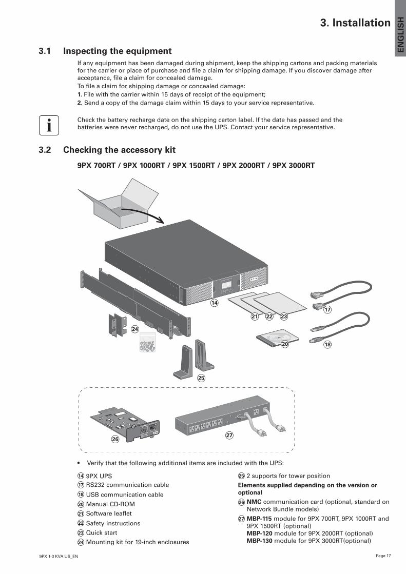
9PX 700RT / 9PX 1000RT / 9PX 1500RT / 9PX 2000RT / 9PX 3000RT
3. Installation
14
25
26
24
27
20
21 232217
18
14 9PX UPS17 RS232 communication cable18 USB communication cable20 Manual CD-ROM
21 Software leaflet22 Safety instructions 23 Quick start 24 Mounting kit for 19-inch enclosures
25 2 supports for tower position
Elements supplied depending on the version or optional
26 NMC communication card (optional, standard on Network Bundle models)
27 MBP-115 module for 9PX 700RT, 9PX 1000RT and 9PX 1500RT (optional) MBP-120 module for 9PX 2000RT (optional) MBP-130 module for 9PX 3000RT(optional)
• Verify that the following additional items are included with the UPS:
Page 18 9PX 1-3 KVA US_EN
3.2 Checking the accessory kit
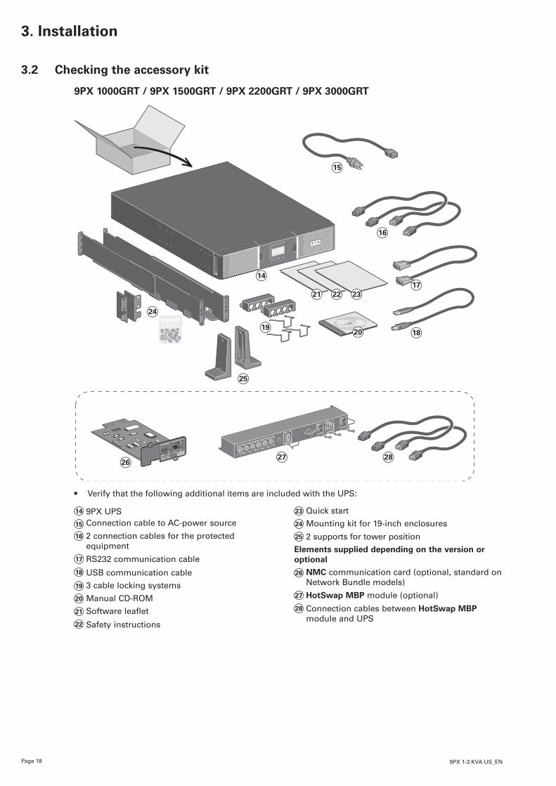
9PX 1000GRT / 9PX 1500GRT / 9PX 2200GRT / 9PX 3000GRT
3. Installation
14
19
25
26
24
27
20
21 2322
16
28
15
17
18
14 9PX UPS15 Connection cable to AC-power source16 2 connection cables for the protected
equipment17 RS232 communication cable18 USB communication cable
19 3 cable locking systems20 Manual CD-ROM
21 Software leaflet22 Safety instructions
23 Quick start24 Mounting kit for 19-inch enclosures25 2 supports for tower position
Elements supplied depending on the version or optional
26 NMC communication card (optional, standard on Network Bundle models)
27 HotSwap MBP module (optional)28 Connection cables between HotSwap MBP
module and UPS
• Verify that the following additional items are included with the UPS:
Page 199PX 1-3 KVA US_EN
EN
GLI
SH
3.2 Checking the accessory kit
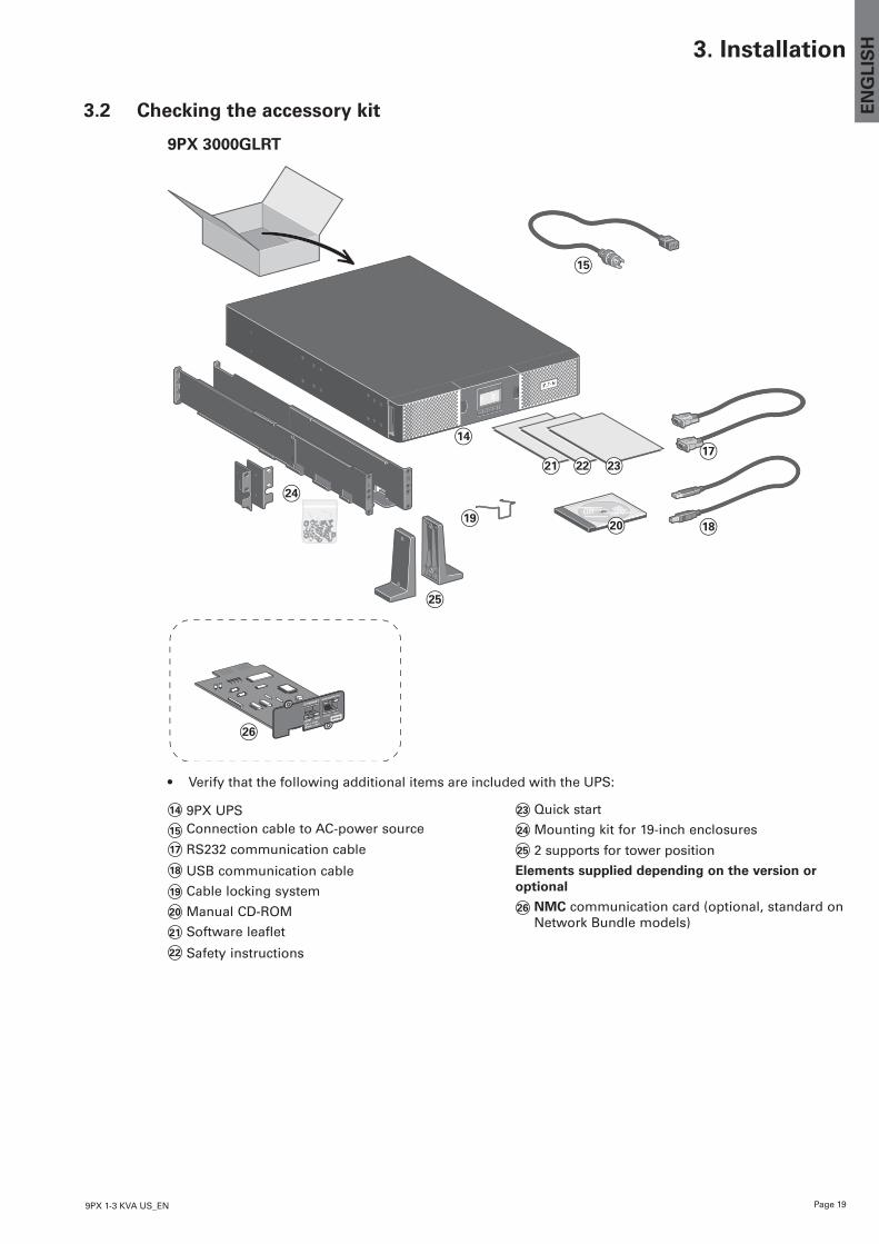
9PX 3000GLRT
3. Installation
14
19
25
26
24
20
21 2322
15
17
18
14 9PX UPS15 Connection cable to AC-power source17 RS232 communication cable18 USB communication cable
19 Cable locking system20 Manual CD-ROM
21 Software leaflet22 Safety instructions
23 Quick start24 Mounting kit for 19-inch enclosures25 2 supports for tower position
Elements supplied depending on the version or optional
26 NMC communication card (optional, standard on Network Bundle models)
• Verify that the following additional items are included with the UPS:
Page 20 9PX 1-3 KVA US_EN
3. Installation
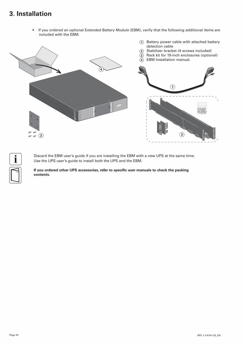
• If you ordered an optional Extended Battery Module (EBM), verify that the following additional items are included with the EBM:
3
4
2
1
1 Battery power cable with attached battery detection cable
2 Stabilizer bracket (4 screws included)3 Rack kit for 19-inch enclosures (optional)4 EBM Installation manual.
Discard the EBM user’s guide if you are installing the EBM with a new UPS at the same time. Use the UPS user’s guide to install both the UPS and the EBM.
If you ordered other UPS accessories, refer to specific user manuals to check the packing contents.
Page 219PX 1-3 KVA US_EN
EN
GLI
SH3. Installation
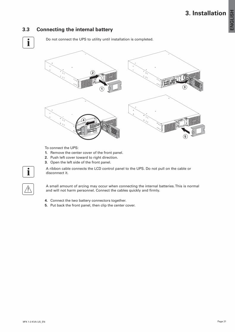
3.3 Connecting the internal battery
Do not connect the UPS to utility until installation is completed.
3
5
2
1
4
To connect the UPS:1. Remove the center cover of the front panel.2. Push left cover toward to right direction.3. Open the left side of the front panel.
A ribbon cable connects the LCD control panel to the UPS. Do not pull on the cable or disconnect it.
A small amount of arcing may occur when connecting the internal batteries. This is normal and will not harm personnel. Connect the cables quickly and firmly.
4. Connect the two battery connectors together.5. Put back the front panel, then clip the center cover.
Page 22 9PX 1-3 KVA US_EN
3. Installation
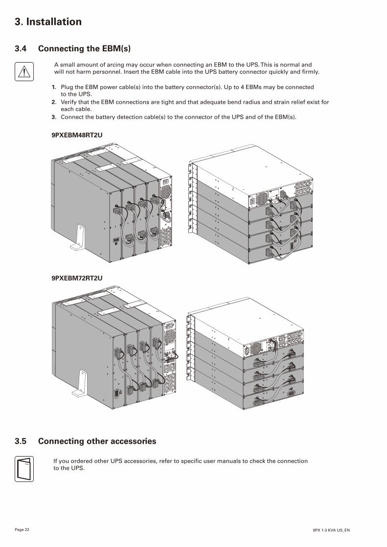
3.4 Connecting the EBM(s)
A small amount of arcing may occur when connecting an EBM to the UPS. This is normal and will not harm personnel. Insert the EBM cable into the UPS battery connector quickly and
1. Plug the EBM power cable(s) into the battery connector(s). Up to 4 EBMs may be connected to the UPS.
2. Verify that the EBM connections are tight and that adequate bend radius and strain relief exist for each cable.
3. Connect the battery detection cable(s) to the connector of the UPS and of the EBM(s).
3.5 Connecting other accessories
If you ordered other UPS accessories, refer to user manuals to check the connection to the UPS.
9PXEBM48RT2U
9PXEBM72RT2U
Page 239PX 1-3 KVA US_EN
EN
GLI
SH3. Installation
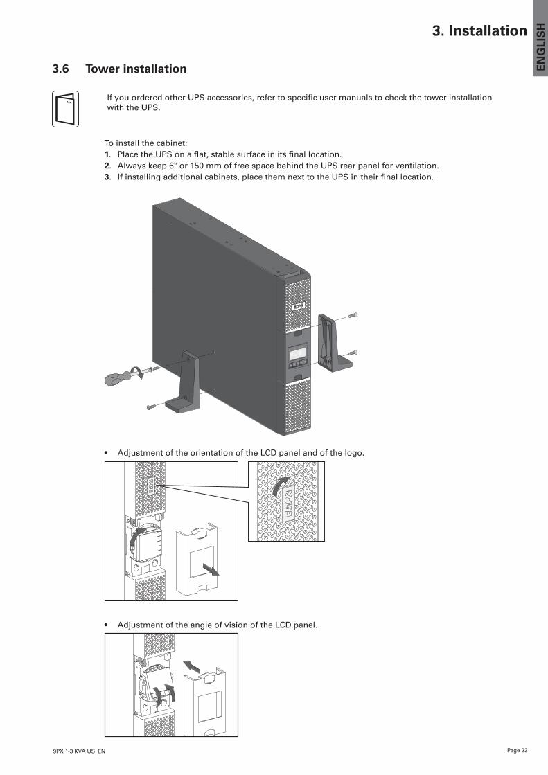
3.6 Tower installation
• Adjustment of the orientation of the LCD panel and of the logo.
• Adjustment of the angle of vision of the LCD panel.
IfyouorderedotherUPSaccessories,refertospecificusermanualstocheckthetowerinstallationwith the UPS.
To install the cabinet:1. PlacetheUPSonaflat,stablesurfaceinitsfinallocation.2. Always keep 6" or 150 mm of free space behind the UPS rear panel for ventilation.3. Ifinstallingadditionalcabinets,placethemnexttotheUPSintheirfinallocation.
Page 24 9PX 1-3 KVA US_EN
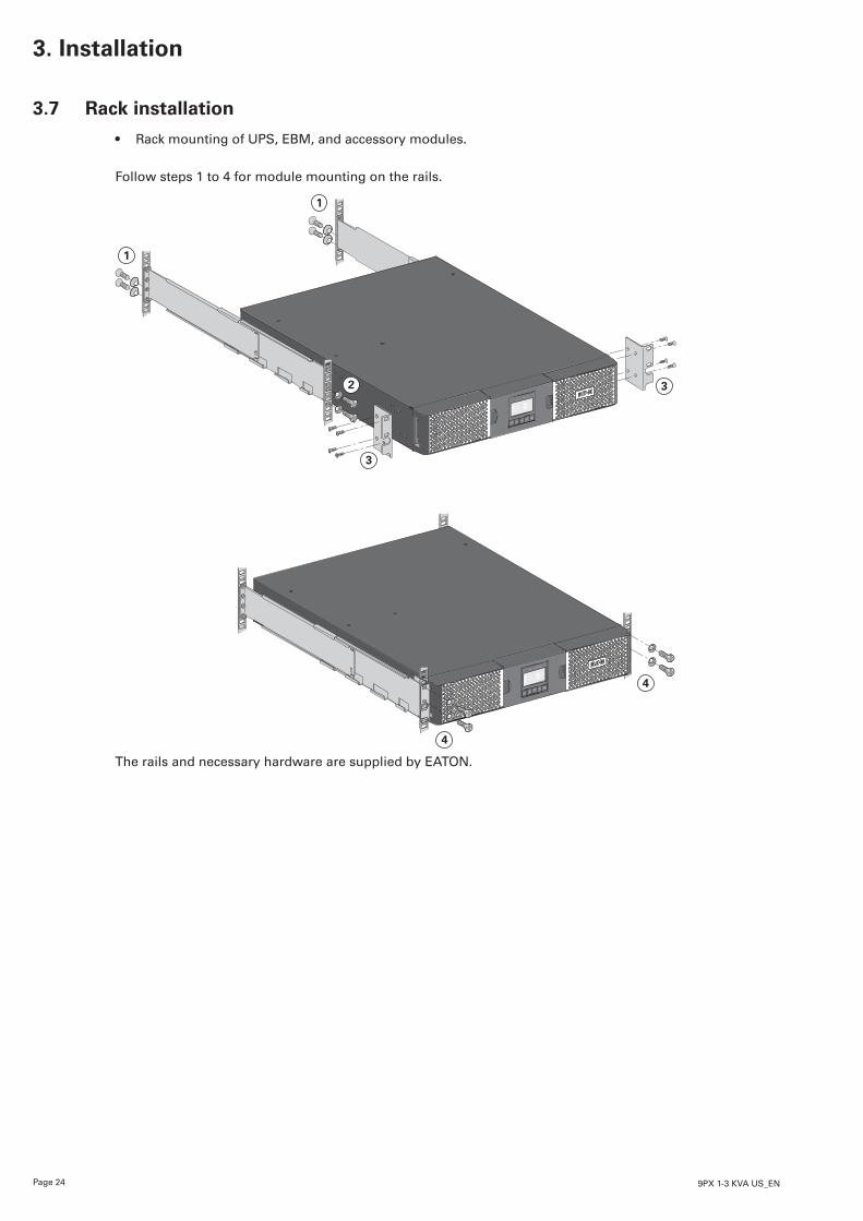
3.7 Rack installation
• Rack mounting of UPS, EBM, and accessory modules.
Follow steps 1 to 4 for module mounting on the rails.
3
3
4
4
2
1
1
The rails and necessary hardware are supplied by EATON.
3. Installation
Page 259PX 1-3 KVA US_EN
EN
GLI
SH3. Installation
3.8 UPS connection without HotSwap MBP module
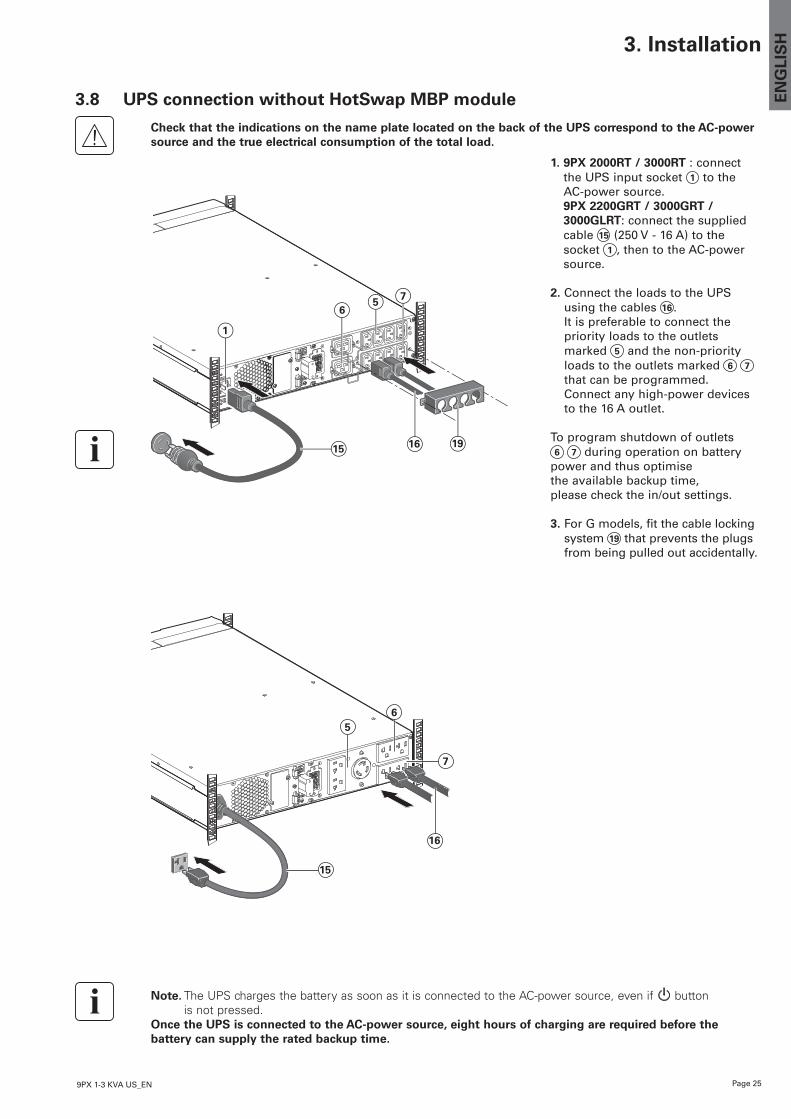
Check that the indications on the name plate located on the back of the UPS correspond to the AC-power source and the true electrical consumption of the total load.
15
1
16 19
76
5
1. 9PX 2000RT / 3000RT : connect the UPS input socket 1 to the AC-power source. 9PX 2200GRT / 3000GRT / 3000GLRT: connect the supplied cable 15 (250 V - 16 A) to the socket 1 , then to the AC-power source.
2. Connect the loads to the UPS using the cables 16 . It is preferable to connect the priority loads to the outlets marked 5 and the non-priority loads to the outlets marked 6 7 that can be programmed. Connect any high-power devices to the 16 A outlet.
To program shutdown of outlets 6 7 during operation on battery
power and thus optimise the available backup time, please check the in/out settings.
3. For G models, fit the cable locking system 19 that prevents the plugs from being pulled out accidentally.
Note. The UPS charges the battery as soon as it is connected to the AC-power source, even if button is not pressed.
Once the UPS is connected to the AC-power source, eight hours of charging are required before the battery can supply the rated backup time.
15
7
16
65
Page 26 9PX 1-3 KVA US_EN
3. Installation
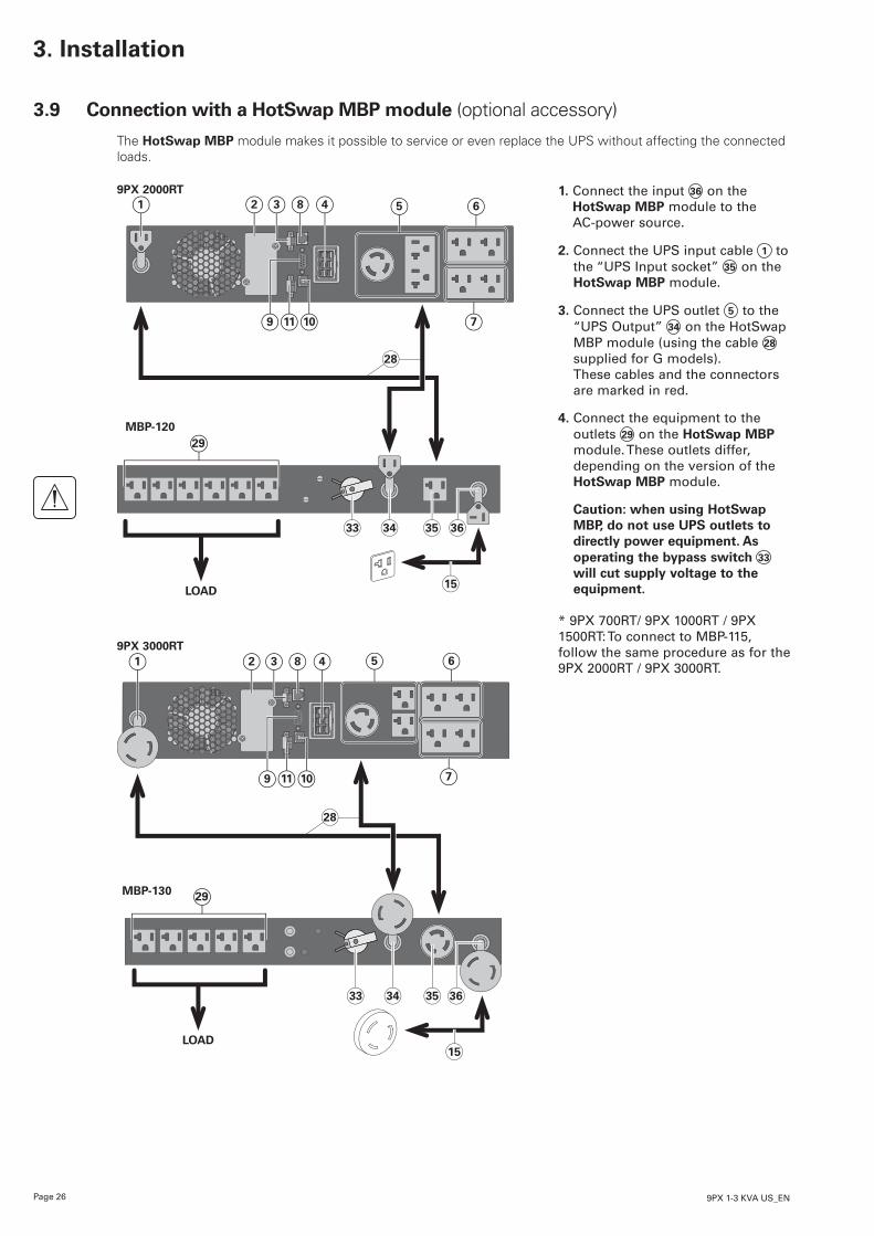
3.9 Connection with a HotSwap MBP module (optional accessory)
The HotSwap MBP module makes it possible to service or even replace the UPS without affecting the connected loads.
9PX 2000RT
MBP-120
LOAD15
28
1 82 43 5 6
9 1011 7
29
33 34 35 36
9PX 3000RT
MBP-130
LOAD15
28
1 82 43 5 6
9 1011 7
29
33 34 35 36
1. Connect the input 36 on the HotSwap MBP module to the AC-power source.
2. Connect the UPS input cable 1 to the “UPS Input socket” 35 on the HotSwap MBP module.
3. Connect the UPS outlet 5 to the “UPS Output” 34 on the HotSwap MBP module (using the cable 28 supplied for G models). These cables and the connectors are marked in red.
4. Connect the equipment to the outlets 29 on the HotSwap MBP module. These outlets differ, depending on the version of the HotSwap MBP module. Caution: when using HotSwap MBP, do not use UPS outlets to directly power equipment. As operating the bypass switch 33 will cut supply voltage to the equipment.
* 9PX 700RT/ 9PX 1000RT / 9PX 1500RT: To connect to MBP-115, follow the same procedure as for the 9PX 2000RT / 9PX 3000RT.
Page 279PX 1-3 KVA US_EN
EN
GLI
SH3. Installation
9PX 2200GRT & 9PX 3000GRT
1
MBP
LOAD
29 30 3331 34 35 36
15
28
32
6 7
5
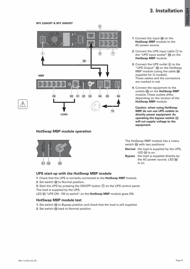
1. Connect the input 36 on the HotSwap MBP module to the AC-power source.
2. Connect the UPS input cable 1 to the “UPS Input socket” 35 on the HotSwap MBP module.
3. Connect the UPS outlet 5 to the “UPS Output” 34 on the HotSwap MBP module (using the cable 28 supplied for G models). These cables and the connectors are marked in red.
4. Connect the equipment to the outlets 29 on the HotSwap MBP module. These outlets differ, depending on the version of the HotSwap MBP module. Caution: when using HotSwap MBP, do not use UPS outlets to directly power equipment. As operating the bypass switch 33 will cut supply voltage to the equipment.
HotSwap MBP module operation
32 3331
UPS start-up with the HotSwap MBP module1. Check that the UPS is correctly connected to the HotSwap MBP module.2. Set switch 33 to Normal position.3. Start the UPS by pressing the ON/OFF button on the UPS control panel. The load is supplied by the UPS.LED 31 "UPS ON - OK to switch" on the HotSwap MBP module goes ON.
HotSwap MBP module test1. Set switch 33 to Bypass position and check that the load is still supplied.2. Set switch 33 back to Normal position.
The HotSwap MBP module has a rotary switch 33 with two positions:
Normal the load is supplied by the UPS, LED 31 is on.
Bypass the load is supplied directly by the AC-power source. LED 32 is on.
Page 28 9PX 1-3 KVA US_EN
4. Communication
4.1 Communication ports
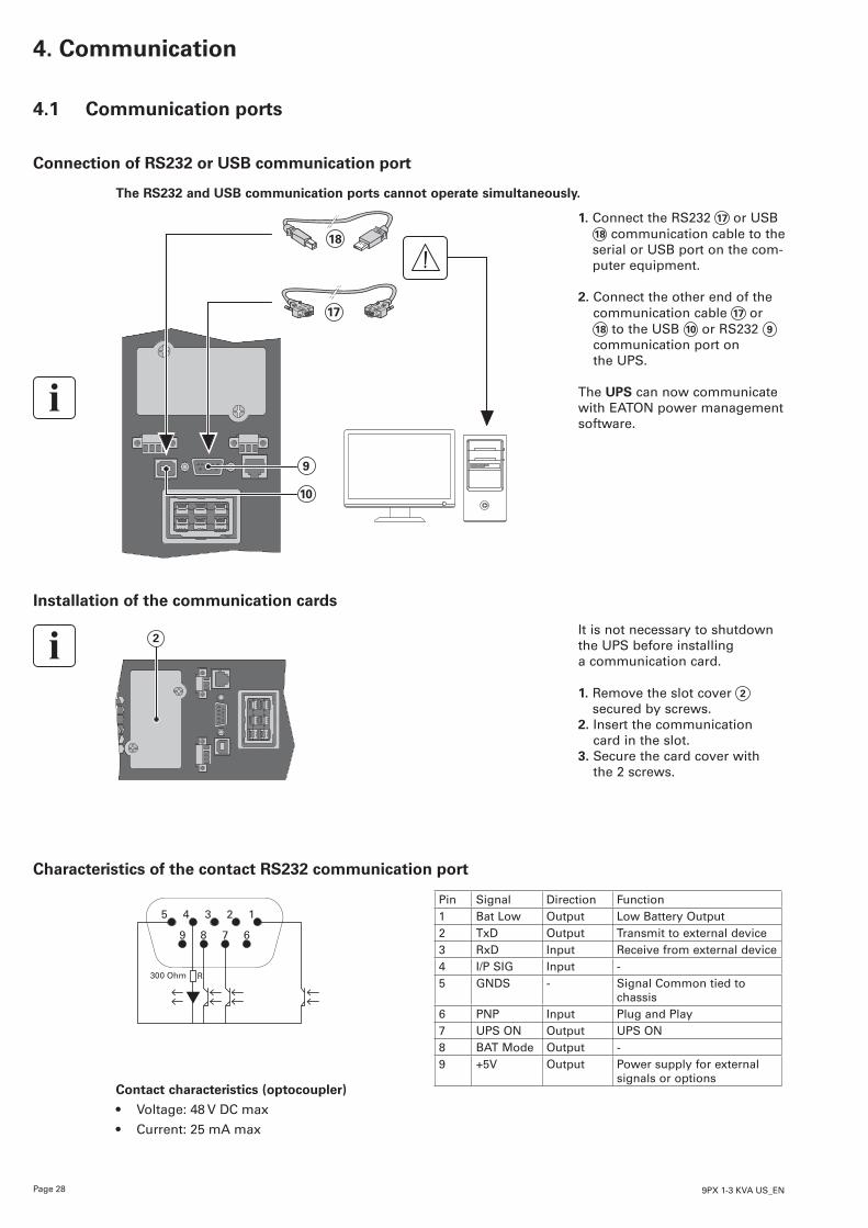
Connection of RS232 or USB communication port
The RS232 and USB communication ports cannot operate simultaneously.
9
10
17
18
1. Connect the RS232 17 or USB 18 communication cable to the serial or USB port on the com-puter equipment.
2. Connect the other end of the communication cable 17 or 18 to the USB 10 or RS232 9 communication port on the UPS.
The UPS can now communicate with EATON power management software.
Installation of the communication cards
2It is not necessary to shutdown the UPS before installing a communication card.
1. Remove the slot cover 2
secured by screws.2. Insert the communication
card in the slot.3. Secure the card cover with
the 2 screws.
Characteristics of the contact RS232 communication port
1
6789
300 Ohm R
2345Pin Signal Direction Function1 Bat Low Output Low Battery Output2 TxD Output Transmit to external device3 RxD Input Receive from external device4 I/P SIG Input -5 GNDS - Signal Common tied to
chassis6 PNP Input Plug and Play7 UPS ON Output UPS ON8 BAT Mode Output -9 +5V Output Power supply for external
signals or optionsContact characteristics (optocoupler)
• Voltage: 48 V DC max
• Current: 25 mA max
Page 299PX 1-3 KVA US_EN
EN
GLI
SH
4.2 UPS remote control functions
Programmable Signal Inputs
The 9PX incorporates 3 programmable signal inputs: one Remote Power Off (RPO) input terminal, one RemoteOn/Off(ROO)inputterminal,oneRS-232input(pin-4).Signalinputscanbeconfigured (seeSettings>Comsettings>SignalInputonpage 15)tohaveoneofthefollowingfunctions:
Function DescriptionNo No function, please choose a function if you want to use input signalRPO Remote Power Off (RPO) is used to shutdown the UPS remotelyROO Remote On/Off allows remote action of button to switch On/Off the UPS.
(Cold start is prohibited while using the ROO function)Forced bypass If feeding the load the unit goes to bypass operation and stays there regardless of
the bypass state until the input is inactivatedBuilding alarm
Active input generates an alarm “building alarm”
On generator Active input disables synchronization and transfers to bypassRemote shutdown
ActiveinputturnsUPSoutput(oroutletgroups)offafterauserdefinedshutdowndelay but keeps on charging batteries according to a selected charging scheme, inactive input does not abort shutdown countdown. Depending on the “Restart” parameter (see Settings > Com Settings > Shutdown commands on page 16) the unit may startup automatically.
Warning Signal inputs have no function by default please choose a function through the LCD (Settings > Com settings > Input signals on page 15).
Seebelow2examplesofconfigurationwithRPOterminalusedasRPOfunctionandROOterminaluseasROO function:
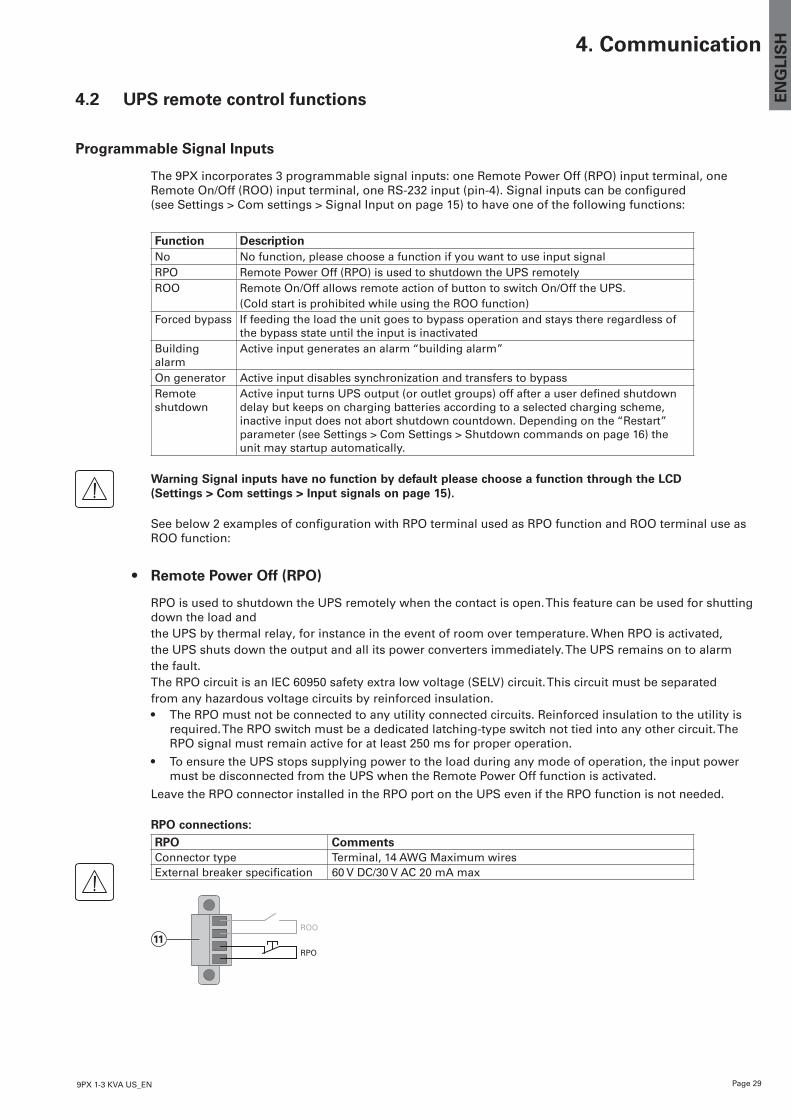
• Remote Power Off (RPO)
RPO is used to shutdown the UPS remotely when the contact is open. This feature can be used for shutting down the load andthe UPS by thermal relay, for instance in the event of room over temperature. When RPO is activated,the UPS shuts down the output and all its power converters immediately. The UPS remains on to alarmthe fault.The RPO circuit is an IEC 60950 safety extra low voltage (SELV) circuit. This circuit must be separatedfrom any hazardous voltage circuits by reinforced insulation.• The RPO must not be connected to any utility connected circuits. Reinforced insulation to the utility is
required. The RPO switch must be a dedicated latching-type switch not tied into any other circuit. The RPO signal must remain active for at least 250 ms for proper operation.
• To ensure the UPS stops supplying power to the load during any mode of operation, the input power must be disconnected from the UPS when the Remote Power Off function is activated.
Leave the RPO connector installed in the RPO port on the UPS even if the RPO function is not needed.
RPO connections:RPO CommentsConnector type Terminal, 14 AWG Maximum wiresExternalbreakerspecification 60 V DC/30 V AC 20 mA max
RPO
11ROO
4. Communication
Page 30 9PX 1-3 KVA US_EN
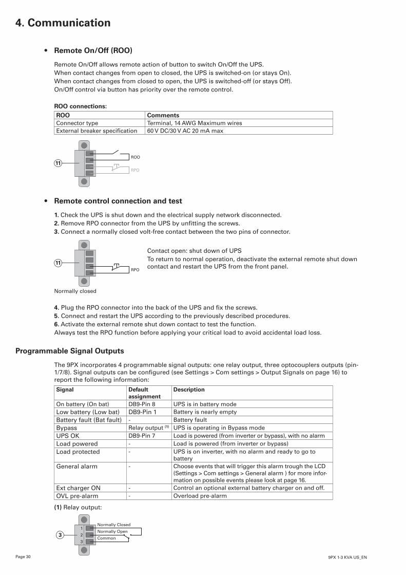
• Remote On/Off (ROO)
Remote On/Off allows remote action of button to switch On/Off the UPS.When contact changes from open to closed, the UPS is switched-on (or stays On).When contact changes from closed to open, the UPS is switched-off (or stays Off).On/Off control via button has priority over the remote control.
ROO connections:ROO CommentsConnector type Terminal, 14 AWG Maximum wiresExternalbreakerspecification 60 V DC/30 V AC 20 mA max
RPO
11ROO
• Remote control connection and test
1. Check the UPS is shut down and the electrical supply network disconnected.2. RemoveRPOconnectorfromtheUPSbyunfittingthescrews.3. Connect a normally closed volt-free contact between the two pins of connector.
RPO
11
Normally closed
Contact open: shut down of UPSTo return to normal operation, deactivate the external remote shut down contact and restart the UPS from the front panel.
4.PlugtheRPOconnectorintothebackoftheUPSandfixthescrews.5. Connect and restart the UPS according to the previously described procedures.6. Activate the external remote shut down contact to test the function.Always test the RPO function before applying your critical load to avoid accidental load loss.
Programmable Signal Outputs
The 9PX incorporates 4 programmable signal outputs: one relay output, three optocouplers outputs (pin-1/7/8).Signaloutputscanbeconfigured(seeSettings>Comsettings>OutputSignalsonpage16)toreport the following information:
Signal Default assignment
Description
On battery (On bat) DB9-Pin 8 UPS is in battery modeLow battery (Low bat) DB9-Pin 1 Battery is nearly empty Battery fault (Bat fault) - Battery faultBypass Relay output (1) UPS is operating in Bypass modeUPS OK DB9-Pin 7 Load is powered (from inverter or bypass), with no alarmLoad powered - Load is powered (from inverter or bypass) Load protected - UPS is on inverter, with no alarm and ready to go to
batteryGeneral alarm - Choose events that will trigger this alarm trough the LCD
(Settings > Com settings > General alarm ) for more infor-mation on possible events please look at page 16.
Ext charger ON - Control an optional external battery charger on and off.OVL pre-alarm - Overload pre-alarm
(1) Relay output:
Normally Closed
Normally Open
Common
1
2
33
4. Communication
Page 319PX 1-3 KVA US_EN
EN
GLI
SH4. Communication
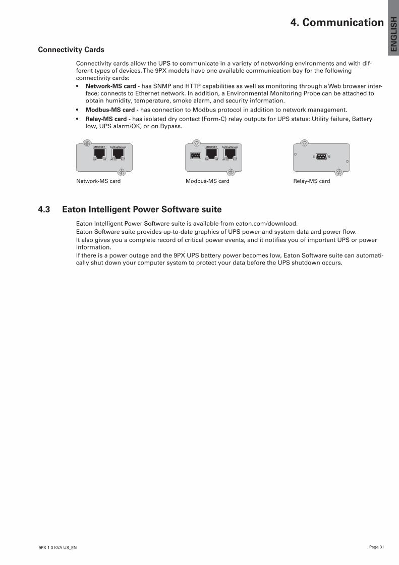
Connectivity Cards
Connectivity cards allow the UPS to communicate in a variety of networking environments and with dif-ferent types of devices. The 9PX models have one available communication bay for the following connectivity cards:• Network-MS card - has SNMP and HTTP capabilities as well as monitoring through a Web browser inter-
face; connects to Ethernet network. In addition, a Environmental Monitoring Probe can be attached to obtain humidity, temperature, smoke alarm, and security information.
• Modbus-MS card - has connection to Modbus protocol in addition to network management.
• Relay-MS card - has isolated dry contact (Form-C) relay outputs for UPS status: Utility failure, Battery low, UPS alarm/OK, or on Bypass.
Relay-MS cardNetwork-MS card
ETHERNET
100M 10M UPS data Reset
Setting/Sensor
Modbus-MS card
ETHERNET
100M 10M UPS data Reset
Setting/Sensor
4.3 Eaton Intelligent Power Software suite
Eaton Intelligent Power Software suite is available from eaton.com/download. EatonSoftwaresuiteprovidesup-to-dategraphicsofUPSpowerandsystemdataandpowerflow.Italsogivesyouacompleterecordofcriticalpowerevents,anditnotifiesyouofimportantUPSorpower information. If there is a power outage and the 9PX UPS battery power becomes low, Eaton Software suite can automati-cally shut down your computer system to protect your data before the UPS shutdown occurs.
Page 32 9PX 1-3 KVA US_EN
5. Operation
5.1 Start-up and Normal operation
To start the UPS:1. Verify that the internal batteries are connected. See "Connecting the internal battery" on page 21.2. If optional EBMs are installed, verify that the EBM are connected to the UPS.
See "Connecting the EBM(s)" on page 22.3. Verify that the UPS power cord is plugged in.4. The UPS front panel display illuminates and shows EATON logo.5. Verify that the UPS status screen shows .6. Press the button on the UPS front panel for at least 2 seconds. The UPS front panel display changes status to "UPS starting...".7. Check the UPS front panel display for active alarms or notices. Resolve any active alarms before
continuing. See "Troubleshooting" on page 39. If the indicator is on, do not proceed until all alarms are clear. Check the UPS status from the front
panel to view the active alarms. Correct the alarms and restart if necessary.8. Verify that the indicator illuminates solid, indicating that the UPS is operating normally and any loads
are powered and protected. The UPS should be in Normal mode.
5.2 Starting the UPS on Battery
Before using this feature, the UPS must have been powered by utility power with output enabled at least once. Battery start can be disabled. See the "Cold start" setting in "ON/OFF Settings" on page 14.
To start the UPS on battery:1. Press the button on the UPS front panel until the UPS front panel display illuminates and shows
a status of "UPS starting...". The UPS transfers from Standby mode to Battery mode. The indicator illuminates solid.
The UPS supplies power to your equipment.2. Check the UPS front panel display for active alarms or notices besides the "Battery mode" notice
and notices that indicate missing utility power. Resolve any active alarms before continuing. See "Troubleshooting" on page 39.
Check the UPS status from the front panel to view the active alarms. Correct the alarms and restart if necessary.
5.3 UPS Shutdown
To shut down the UPS:1. Press the button on the front panel for three seconds. Aconfirmationmessagewillappear. Whenconfirmed,theUPSstartstobeepandshowsastatusof"UPSshuttingOFF...".TheUPSthen
transfers to Standby mode, and the indicator turns off.
5.4 Operating modes
The Eaton 9PX front panel indicates the UPS status through the UPS indicators, see page 11.
Online mode
During Online mode, the indicator illuminates solid and the UPS is powered from the utility. TheUPSmonitorsandchargesthebatteriesasneededandprovidesfilteredpowerprotectiontoyourequipment.OptionalHighEfficiencyandEnergySavingsettingsminimizeheatcontributiontotherackenvironment. See user settings on page 13.
Battery mode
When the UPS is operating during a power outage, the alarm beeps once every ten seconds and the indicator illuminates solid. The necessary energy is provided by the battery.When the utility power returns, the UPS transfers to Online mode operation while the battery recharges.If battery capacity becomes low while on Battery mode, the audible alarm beeps once every 3 seconds. Thiswarningisapproximate,andtheactualtimetoshutdownmayvarysignificantly.Shutdown all applications on the connected equipment because automatic UPS shutdown is imminent.When utility power is restored after the UPS shuts down, the UPS automatically restarts.
Page 339PX 1-3 KVA US_EN
EN
GLI
SH5. Operation
Low-battery warning
• The indicator illuminates solid.
• The audio alarm beeps every three seconds.
The remaining battery power is low. Shut down all applications on the connected equipment because automatic UPS shutdown is imminent.
End of battery backup time
• LCD displays "End of backup time".
• All the LEDs go OFF.
• The audio alarms stops.
Bypass mode
In the event of a UPS overload or internal failure, the UPS transfers your equipment to utility power. Battery mode is not available and your equipment is not protected; however, the utility power continues tobepassivelyfilteredbytheUPS.The indicator illuminates.Depending on overload conditions, the UPS remains in Bypass mode for at least 5 seconds and will stay in this mode if three transfers to Bypass occur within 20 minutes.The UPS transfers to Bypass mode when:• the user activates Bypass mode through the front panel.
• the UPS detects an internal failure.
• the UPS has an overtemperature condition.
• the UPS has an overload condition listed in table 6 on page 42.
TheUPSshutsdownafteraspecifieddelayforoverloadconditionslistedintable6onpage42. The UPS remains on to alarm the fault.
5.5 Return of AC Input Power
Following an outage, the UPS restarts automatically when AC input power returns (unless the restart function has been disabled) and the load is supplied again.
5.6 Setting High Efficiency mode
InHighEfficiencymode,theUPSoperatesnormallyonBypassandtransferstoOnline(orBattery)modeinlessthan10mswhenutilityfails.TransferstoHighEfficiencymodewillbeactiveafter5minutesofBypassvoltage monitoring: if Bypass quality is not in tolerance, then the UPS will remain in Online mode.
Eaton recommends to use the HE mode only to protect IT equipment.
TosettheHighEfficiencymode:1. SelectSettings,In/Outsettings,andHighEfficiencymode.2. SelectEnabledandEntertoconfirm.3. TheUPStransferstoHighEfficiencymodeafter5minutes.
5.7 Configuring Bypass settings
ThefollowingsettingsareavailableforconfiguringBypassoperation.
Changing the settings changes UPS behavior and may result in decreased protection.
Bypass Voltage Low LimitThe default disables a transfer to Bypass if the measured bypass voltage level is below the nominal output voltageminus20%.Youcanconfigurethesettingforanothervoltagevalue.Thissettingcanbeoverruledbythe “Qualify Bypass” setting.
Bypass Voltage High LimitThe default disables a transfer to Bypass if the measured bypass voltage level is above the nominal output voltageplus15%.Youcanconfigurethesettingforanothervoltagevalue. This setting can be overruled by the “Qualify Bypass” setting.
Page 34 9PX 1-3 KVA US_EN
5. Operation
Qualify BypassThedefaultsetting(“Inspec”)allowsatransfertoBypassonlywhenBypassiswithinthefollowingspecifi-cations:• Bypass voltage is between the “Bypass Voltage Low Limit” and “Bypass Voltage High Limit” settings
• Bypass frequency is within nominal frequency 5%.
YoucanprohibitBypass(”Never”)oralwaysallowBypasswithnospecificationchecking(“Always”).For“Always on UPS Fault,” transfer to Bypass is always made on UPS fault; otherwise, operation proceeds as with the default setting.
Synchronization WindowThe UPS tries to synchronize with Bypass when the Bypass frequency is less than the value set for the “Synchronization Window” setting. When the Bypass frequency is more than the set value, the UPS goes to nominal frequency.
Unsynchronized TransfersWhen Qualify Bypass is set to “Always” or “Always on Fault” you can select the interruption time when transferring to bypass, default setting is “Half Cycle” but can be changed to “Full cycle”.
5.8 Configuring battery settings
Automatic battery test
Automatic battery tests are done every week in constant charging mode and at each cycle in ABM mode. Thetestsfrequencycanbemodified. During the test, the UPS transfers to Battery mode and discharges the batteries for 10 seconds under load.
Battery mode is not displayed and battery low alarm does not activate during a battery test.
The battery test may be postponed due to bad conditions, or failed if battery is not ok.
Low battery warning
During discharge, the low battery alarm is activated if the remaining runtime goes below 3 minutes or less than the setting capacity threshold (0 % by default). Thisthresholdcanbemodified.
External battery setting
The number of Extended Battery Module is automatically detected, or can be set manually in number of EBM or in Ah.
Deep discharge protection
This setting is recommended to avoid damaging the battery. Warranty is void if deep discharge protection is disabled.
5.9 Retrieving the Event log
To retrieve the Event log through the display:1. Press any button to activate the menu options, then select Event log.2. Scroll through the listed events.
5.10 Retrieving the Fault log
To retrieve the Fault log through the display:1. Press any button to activate the menu options, then select Fault log.2. Scroll through the listed faults.
Page 359PX 1-3 KVA US_EN
EN
GLI
SH6. UPS maintenance
6.1 Equipment care
For the best preventive maintenance, keep the area around the equipment clean and dust free. If the atmosphere is very dusty, clean the outside of the system with a vacuum cleaner.For full battery life, keep the equipment at an ambient temperature of 25°C (77°F).
If the UPS requires any type of transportation, verify that the UPS is disconnected and turned off.The batteries are rated for a 3-5 year service life. The length of service life varies, depending on the frequency of usage and ambient temperature (life divided by 2 each 10°C above 25°C). Batteries used beyond expected service life will often have severely reduced runtimes. Replace batteriesatleastevery4yearstokeepunitsrunningatpeakefficiency.
6.2 Storing the equipment
If you store the equipment for a long period, recharge the battery every 6 months by connecting the UPS to utility power. The internal batteries charge to 90% capacity in less than 3 hours. However, Eaton recommends that the batteries charge for 48 hours after long-term storage. Check the battery recharge date on the shipping carton label. If the date has passed and the batteries were never recharged, do not use them. Contact your service representative.
6.3 When to replace batteries
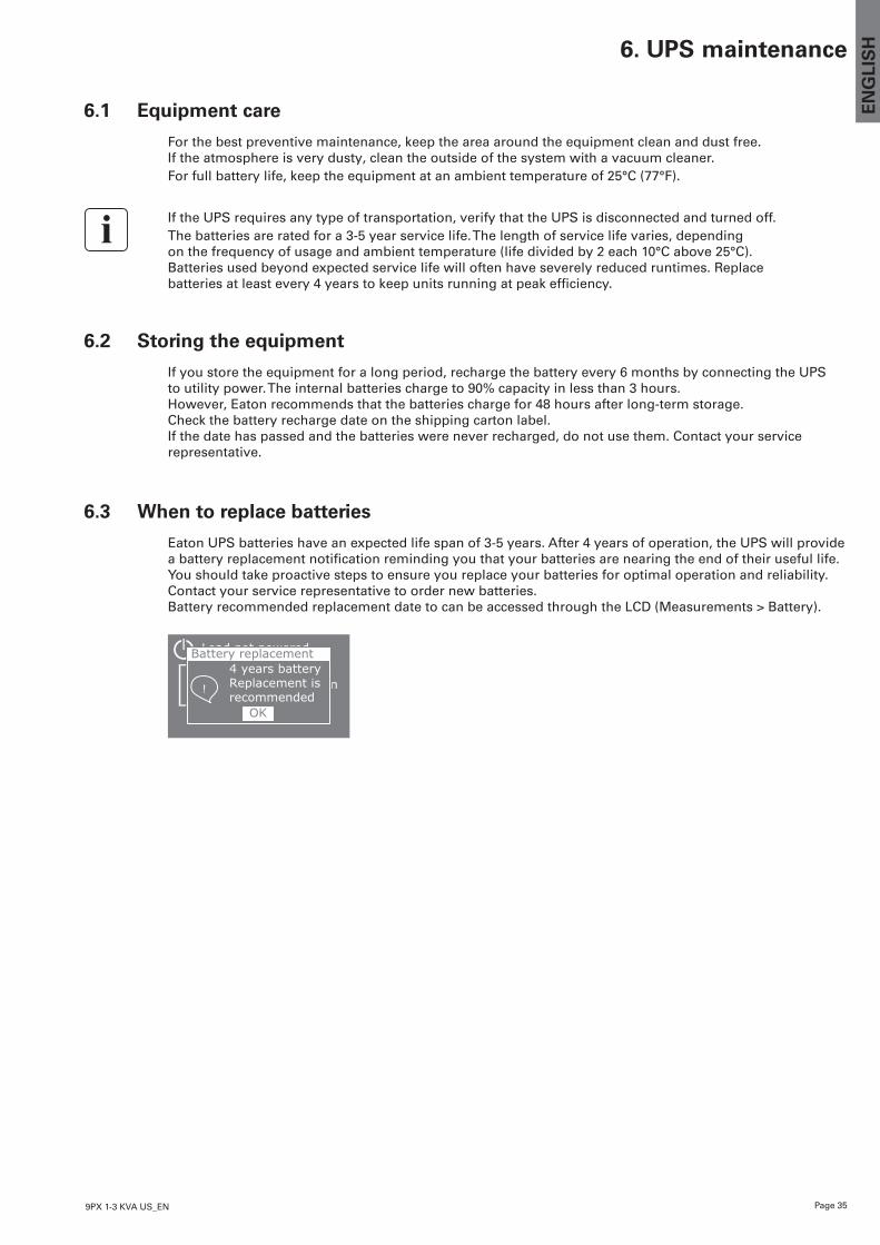
Eaton UPS batteries have an expected life span of 3-5 years. After 4 years of operation, the UPS will provide abatteryreplacementnotificationremindingyouthatyourbatteriesarenearingtheendoftheirusefullife.You should take proactive steps to ensure you replace your batteries for optimal operation and reliability. Contact your service representative to order new batteries. Battery recommended replacement date to can be accessed through the LCD (Measurements > Battery).
-% 100% -kW 100min -kVA 1 EBM
Load not powered 4 years battery Replacement is recommended
Battery replacement
!
OK
Page 36 9PX 1-3 KVA US_EN
6. UPS maintenance
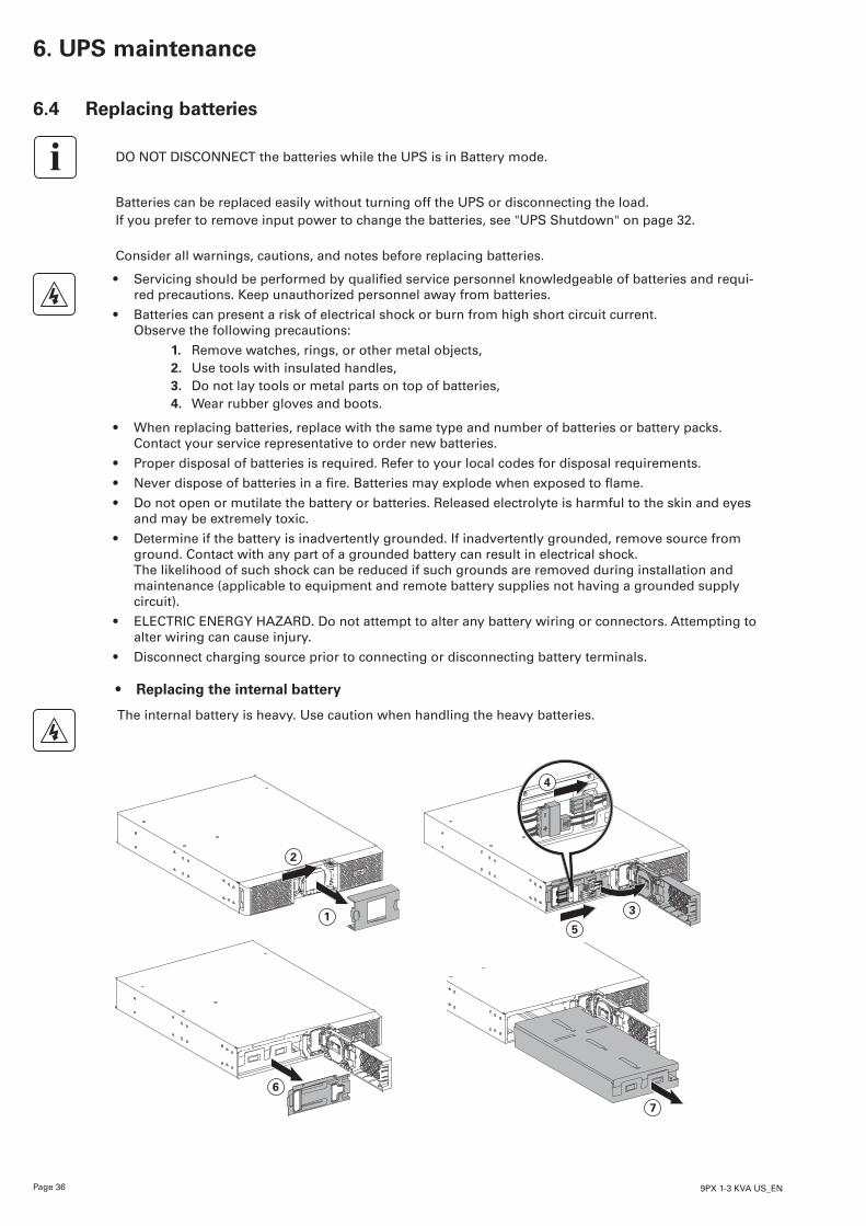
6.4 Replacing batteries
DO NOT DISCONNECT the batteries while the UPS is in Battery mode.
Batteries can be replaced easily without turning off the UPS or disconnecting the load.If you prefer to remove input power to change the batteries, see "UPS Shutdown" on page 32.
Consider all warnings, cautions, and notes before replacing batteries.
• Servicingshouldbeperformedbyqualifiedservicepersonnelknowledgeableofbatteriesandrequi-red precautions. Keep unauthorized personnel away from batteries.
• Batteries can present a risk of electrical shock or burn from high short circuit current. Observe the following precautions:
1. Remove watches, rings, or other metal objects,2. Use tools with insulated handles, 3. Do not lay tools or metal parts on top of batteries, 4. Wear rubber gloves and boots.
• When replacing batteries, replace with the same type and number of batteries or battery packs. Contact your service representative to order new batteries.
• Proper disposal of batteries is required. Refer to your local codes for disposal requirements.
• Neverdisposeofbatteriesinafire.Batteriesmayexplodewhenexposedtoflame.
• Do not open or mutilate the battery or batteries. Released electrolyte is harmful to the skin and eyes and may be extremely toxic.
• Determine if the battery is inadvertently grounded. If inadvertently grounded, remove source from ground. Contact with any part of a grounded battery can result in electrical shock. The likelihood of such shock can be reduced if such grounds are removed during installation and maintenance (applicable to equipment and remote battery supplies not having a grounded supply circuit).
• ELECTRIC ENERGY HAZARD. Do not attempt to alter any battery wiring or connectors. Attempting to alter wiring can cause injury.
• Disconnect charging source prior to connecting or disconnecting battery terminals.
• Replacing the internal battery
The internal battery is heavy. Use caution when handling the heavy batteries.
3
5
6
7
2
1
4
Page 379PX 1-3 KVA US_EN
EN
GLI
SH6. UPS maintenance
To replace the battery pack:1. Remove the center cover of the front panel.2. Push left cover toward to right direction.3. Open the battery door.4. Disconnect the battery connectors.
A ribbon cable connects the LCD control panel to the UPS. Do not pull on the cable or disconnect it.
5. Remove the two screws to pull out the metal protection cover of the battery.6. Pullouttheplastichandleofthebatterypack,andslidethepackoutslowlyontoaflatandstablesur-
face. Use two hands to support the battery pack. See "Recycling the used equipment" on page 38 for proper disposal.
7. Verify that the replacement batteries have the same rating as the batteries being replaced.8. PutthenewbatterypackintotheUPS.Pushthebatterypackfirmlytoensureaproperconnection.9. Screw back the metal protection cover and the front panel, then clip the center cover.10. Continue to “Testing new batteries” on page 37.
• Replacing the EBM(s)
The EBM is heavy. Lifting the cabinet into a rack requires a minimum of two people.
To replace the EBM(s):1. Unplug the EBM power cable and battery detection cable from the UPS. If additional EBM(s) are installed, unplug the EBM power cable and battery detection cable
from each EBM.2. Replace the EBM(s). See "Recycling the used equipment" on page 38 for proper disposal.
A small amount of arcing may occur when connecting an EBM to the UPS. This is normal and will notharmpersonnel.InserttheEBMcableintotheUPSbatteryconnectorquicklyandfirmly.
3. Plug the EBM cable(s) into the battery connector(s). Up to four EBMs may be connected to the UPS.4. Verify that the EBM connections are tight and that adequate bend radius and strain relief exist for each
cable.5. Connect the battery detection cable(s) to the connector of the UPS and of the EBM(s).
• Testing new batteriesTo test new batteries:1. Charge the batteries for 48 hours.2. Press any button to activate the menu options.3. Select Control then Start battery test. The UPS starts a battery test if the batteries are fully charged, the UPS is in Normal mode with no active
alarms, and the bypass voltage is acceptable. During the battery test, the UPS transfers to Battery mode and discharges the batteries for 25 seconds.
The front panel displays "Battery test in progress" and the percentage of the test completed.
Page 38 9PX 1-3 KVA US_EN
6. UPS maintenance
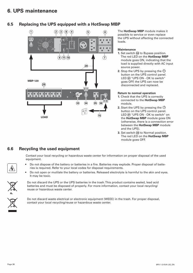
6.5 Replacing the UPS equipped with a HotSwap MBP
The HotSwap MBP module makes it possible to service or even replace the UPS without affecting the connected loads.
Maintenance 1. Set switch 33 to Bypass position.
The red LED on the HotSwap MBP module goes ON, indicating that the load is supplied directly with AC input source power.
2. Stop the UPS by pressing the button on the UPS control panel. LED 31 "UPS ON - OK to switch" goes OFF, the UPS can now be disconnected and replaced.
Return to normal operation 1. Check that the UPS is correctly
connected to the HotSwap MBP module.
2. Start the UPS by pressing the button on the UPS control panel. LED 31 "UPS ON - OK to switch" on the HotSwap MBP module goes ON (otherwise, there is a connection error between the HotSwap MBP module and the UPS).
3. Set switch 33 to Normal position. The red LED on the HotSwap MBP module goes OFF.
6.6 Recycling the used equipment
Contact your local recycling or hazardous waste center for information on proper disposal of the used equipment.
• Donotdisposeofthebatteryorbatteriesinafire.Batteriesmayexplode.Properdisposalofbatte-ries is required. Refer to your local codes for disposal requirements.
• Do not open or mutilate the battery or batteries. Released electrolyte is harmful to the skin and eyes. It may be toxic.
Do not discard the UPS or the UPS batteries in the trash. This product contains sealed, lead acid batteries and must be disposed of properly. For more information, contact your local recycling/reuse or hazardous waste center.
Do not discard waste electrical or electronic equipment (WEEE) in the trash. For proper disposal, contact your local recycling/reuse or hazardous waste center.
MBP-120
LOAD15
28
1 82 43 5 6
9 1011 7
29
33 34 35 36
Page 399PX 1-3 KVA US_EN
EN
GLI
SH7. Troubleshooting
The Eaton 9PX are designed for durable, automatic operation and also alert you whenever potential ope-rating problems may occur. Usually the alarms shown by the control panel do not mean that the output power is affected. Instead, they are preventive alarms intended to alert the user.• Events are silent status information that are recorded into the Event log. Example = "AC freq in range".
• Alarms are recorded into the Event log and displayed on the LCD status screen with the logo blinking. Some alarms may be announced by a beep every 3 seconds. Example = "Battery low".
• Faults are announced by a continuous beep and red LED, recorded into the Fault log and displayed on theLCDwithaspecificmessagebox.Example=Out.shortcircuit.
Use the following troubleshooting chart to determine the UPS alarm condition.
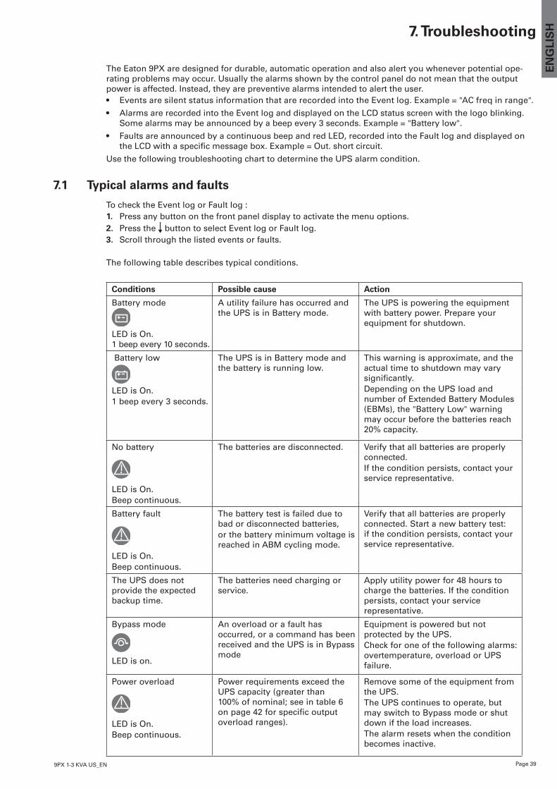
7.1 Typical alarms and faults
To check the Event log or Fault log :1. Press any button on the front panel display to activate the menu options.2. Press the button to select Event log or Fault log.3. Scroll through the listed events or faults.
The following table describes typical conditions.
Conditions Possible cause Action
Battery mode
LED is On. 1 beep every 10 seconds.
A utility failure has occurred and the UPS is in Battery mode.
The UPS is powering the equipment with battery power. Prepare your equipment for shutdown.
Battery low The UPS is in Battery mode and the battery is running low.
This warning is approximate, and the actual time to shutdown may vary significantly.Depending on the UPS load and number of Extended Battery Modules (EBMs), the "Battery Low" warning may occur before the batteries reach 20% capacity.
LED is On.1 beep every 3 seconds.
No battery The batteries are disconnected. Verify that all batteries are properly connected.If the condition persists, contact your service representative.
LED is On.Beep continuous.
Battery fault The battery test is failed due to bad or disconnected batteries,or the battery minimum voltage is reached in ABM cycling mode.
Verify that all batteries are properly connected. Start a new battery test: if the condition persists, contact your service representative.
LED is On.Beep continuous.
The UPS does not provide the expected backup time.
The batteries need charging or service.
Apply utility power for 48 hours to charge the batteries. If the condition persists, contact your service representative.
Bypass mode An overload or a fault has occurred, or a command has been received and the UPS is in Bypass mode
Equipment is powered but not protected by the UPS.Check for one of the following alarms: overtemperature, overload or UPS failure.LED is on.
Power overload Power requirements exceed the UPS capacity (greater than 100% of nominal; see in table 6 on page 42 for specific output overload ranges).
Remove some of the equipment from the UPS.The UPS continues to operate, but may switch to Bypass mode or shut down if the load increases.The alarm resets when the condition becomes inactive.
LED is On.Beep continuous.
Page 40 9PX 1-3 KVA US_EN
7. Troubleshooting
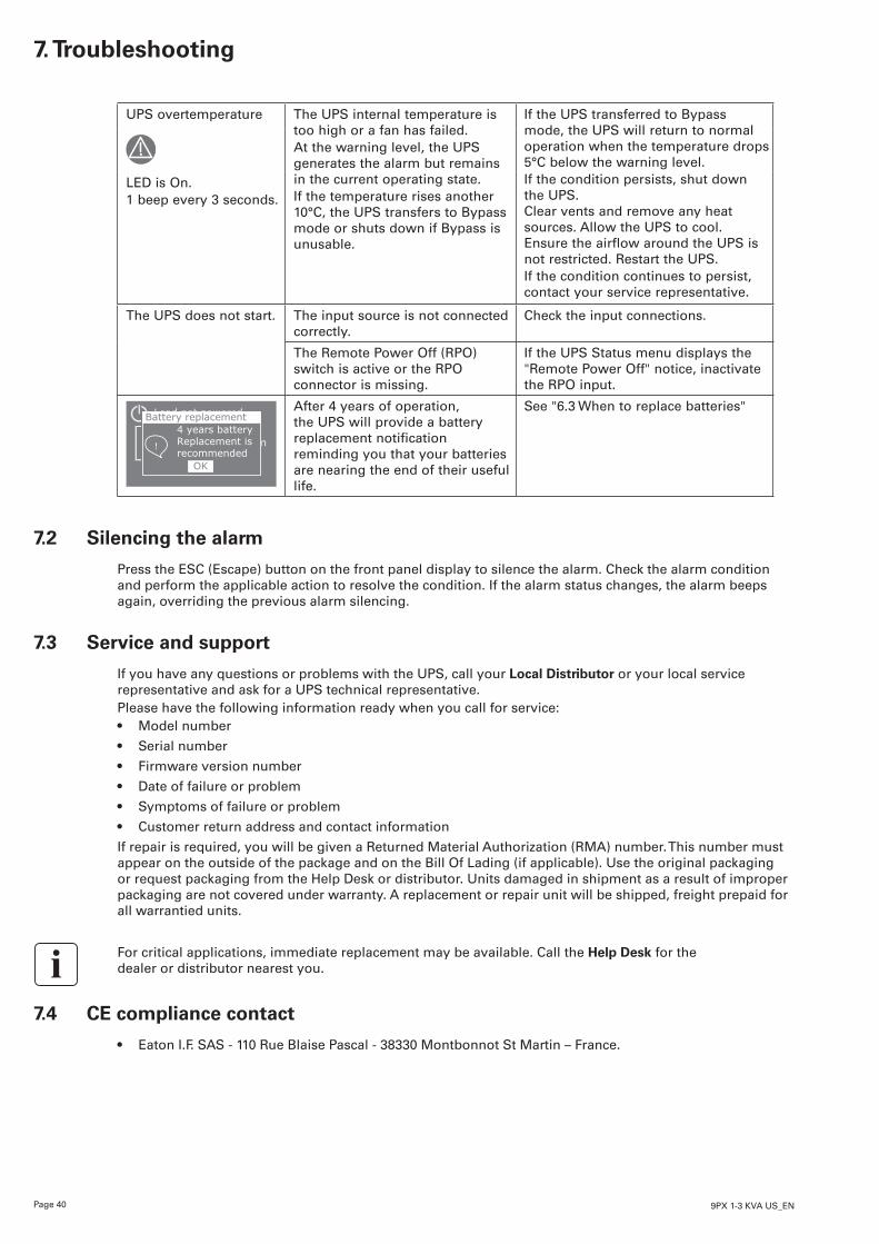
UPS overtemperature The UPS internal temperature is too high or a fan has failed.At the warning level, the UPS generates the alarm but remains in the current operating state.If the temperature rises another 10°C, the UPS transfers to Bypass mode or shuts down if Bypass is unusable.
If the UPS transferred to Bypass mode, the UPS will return to normal operation when the temperature drops 5°C below the warning level.If the condition persists, shut down the UPS. Clear vents and remove any heat sources. Allow the UPS to cool. Ensure the airflow around the UPS is not restricted. Restart the UPS.If the condition continues to persist, contact your service representative.
LED is On.1 beep every 3 seconds.
The UPS does not start. The input source is not connected correctly.
Check the input connections.
The Remote Power Off (RPO) switch is active or the RPO connector is missing.
If the UPS Status menu displays the "Remote Power Off" notice, inactivate the RPO input.
-% 100% -kW 100min -kVA 1 EBM
Load not powered 4 years battery Replacement is recommended
Battery replacement
!
OK
After 4 years of operation, the UPS will provide a battery replacement notification reminding you that your batteries are nearing the end of their useful life.
See "6.3 When to replace batteries"
7.2 Silencing the alarm
Press the ESC (Escape) button on the front panel display to silence the alarm. Check the alarm condition and perform the applicable action to resolve the condition. If the alarm status changes, the alarm beeps again, overriding the previous alarm silencing.
7.3 Service and support
If you have any questions or problems with the UPS, call your Local Distributor or your local service representative and ask for a UPS technical representative.Please have the following information ready when you call for service:• Model number
• Serial number
• Firmware version number
• Date of failure or problem
• Symptoms of failure or problem
• Customer return address and contact information
If repair is required, you will be given a Returned Material Authorization (RMA) number. This number must appear on the outside of the package and on the Bill Of Lading (if applicable). Use the original packaging or request packaging from the Help Desk or distributor. Units damaged in shipment as a result of improper packaging are not covered under warranty. A replacement or repair unit will be shipped, freight prepaid for all warrantied units.
For critical applications, immediate replacement may be available. Call the Help Desk for the dealer or distributor nearest you.
7.4 CE compliance contact
• Eaton I.F. SAS - 110 Rue Blaise Pascal - 38330 Montbonnot St Martin – France.
Page 419PX 1-3 KVA US_EN
EN
GLI
SH8. Specifications
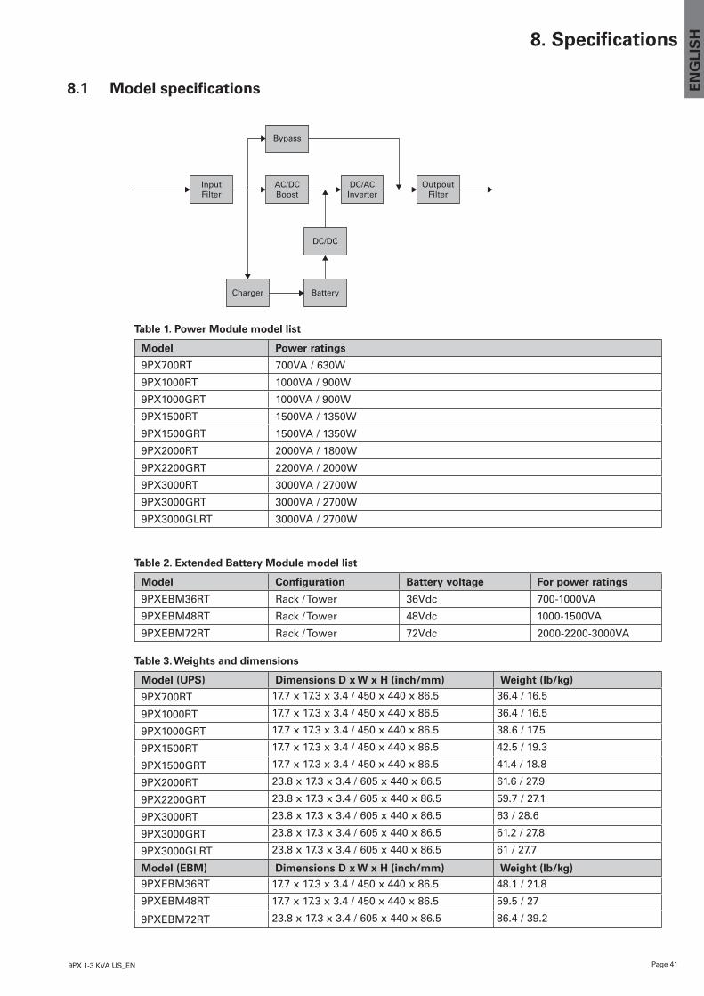
8.1 Model specifications
InputFilter
AC/DCBoost
DC/ACInverter
OutpoutFilter
Bypass
DC/DC
BatteryCharger
Table 1. Power Module model list
Model Power ratings
9PX700RT 700VA / 630W
9PX1000RT 1000VA / 900W
9PX1000GRT 1000VA / 900W
9PX1500RT 1500VA / 1350W
9PX1500GRT 1500VA / 1350W
9PX2000RT 2000VA / 1800W
9PX2200GRT 2200VA / 2000W
9PX3000RT 3000VA / 2700W
9PX3000GRT 3000VA / 2700W
9PX3000GLRT 3000VA / 2700W
Table 2. Extended Battery Module model list
Model Configuration Battery voltage For power ratings
9PXEBM36RT Rack / Tower 36Vdc 700-1000VA
9PXEBM48RT Rack / Tower 48Vdc 1000-1500VA
9PXEBM72RT Rack / Tower 72Vdc 2000-2200-3000VA
Table 3. Weights and dimensions
Model (UPS) Dimensions D x W x H (inch/mm) Weight (lb/kg)
9PX700RT 17.7 x 17.3 x 3.4 / 450 x 440 x 86.5 36.4 / 16.5
9PX1000RT 17.7 x 17.3 x 3.4 / 450 x 440 x 86.5 36.4 / 16.5
9PX1000GRT 17.7 x 17.3 x 3.4 / 450 x 440 x 86.5 38.6 / 17.5
9PX1500RT 17.7 x 17.3 x 3.4 / 450 x 440 x 86.5 42.5 / 19.3
9PX1500GRT 17.7 x 17.3 x 3.4 / 450 x 440 x 86.5 41.4 / 18.8
9PX2000RT 23.8 x 17.3 x 3.4 / 605 x 440 x 86.5 61.6 / 27.9
9PX2200GRT 23.8 x 17.3 x 3.4 / 605 x 440 x 86.5 59.7 / 27.1
9PX3000RT 23.8 x 17.3 x 3.4 / 605 x 440 x 86.5 63 / 28.6
9PX3000GRT 23.8 x 17.3 x 3.4 / 605 x 440 x 86.5 61.2 / 27.8
9PX3000GLRT 23.8 x 17.3 x 3.4 / 605 x 440 x 86.5 61 / 27.7
Model (EBM) Dimensions D x W x H (inch/mm) Weight (lb/kg)9PXEBM36RT 17.7 x 17.3 x 3.4 / 450 x 440 x 86.5 48.1 / 21.8
9PXEBM48RT 17.7 x 17.3 x 3.4 / 450 x 440 x 86.5 59.5 / 27
9PXEBM72RT 23.8 x 17.3 x 3.4 / 605 x 440 x 86.5 86.4 / 39.2
Page 42 9PX 1-3 KVA US_EN
8. Specifications
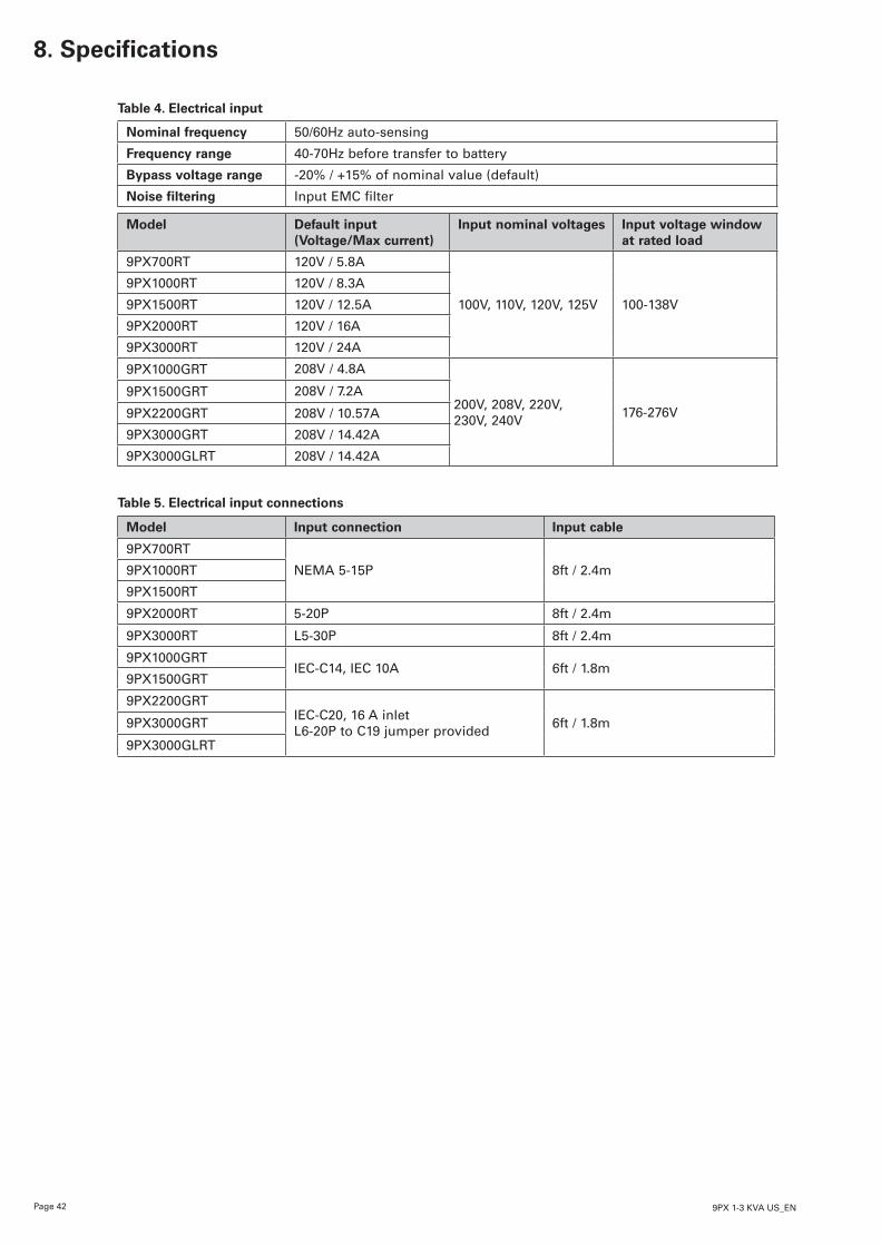
Table 4. Electrical input
Nominal frequency 50/60Hz auto-sensing
Frequency range 40-70Hz before transfer to battery
Bypass voltage range -20% / +15% of nominal value (default)
Noise filtering Input EMC filter
Model Default input(Voltage/Max current)
Input nominal voltages Input voltage window at rated load
9PX700RT 120V / 5.8A
100V, 110V, 120V, 125V 100-138V
9PX1000RT 120V / 8.3A
9PX1500RT 120V / 12.5A
9PX2000RT 120V / 16A
9PX3000RT 120V / 24A
9PX1000GRT 208V / 4.8A
200V, 208V, 220V,230V, 240V 176-276V
9PX1500GRT 208V / 7.2A
9PX2200GRT 208V / 10.57A
9PX3000GRT 208V / 14.42A
9PX3000GLRT 208V / 14.42A
Table 5. Electrical input connections
Model Input connection Input cable
9PX700RT
NEMA 5-15P 8ft / 2.4m9PX1000RT
9PX1500RT
9PX2000RT 5-20P 8ft / 2.4m
9PX3000RT L5-30P 8ft / 2.4m
9PX1000GRTIEC-C14, IEC 10A 6ft / 1.8m
9PX1500GRT
9PX2200GRTIEC-C20, 16 A inlet L6-20P to C19 jumper provided 6ft / 1.8m9PX3000GRT
9PX3000GLRT
Page 439PX 1-3 KVA US_EN
EN
GLI
SH8. Specifications
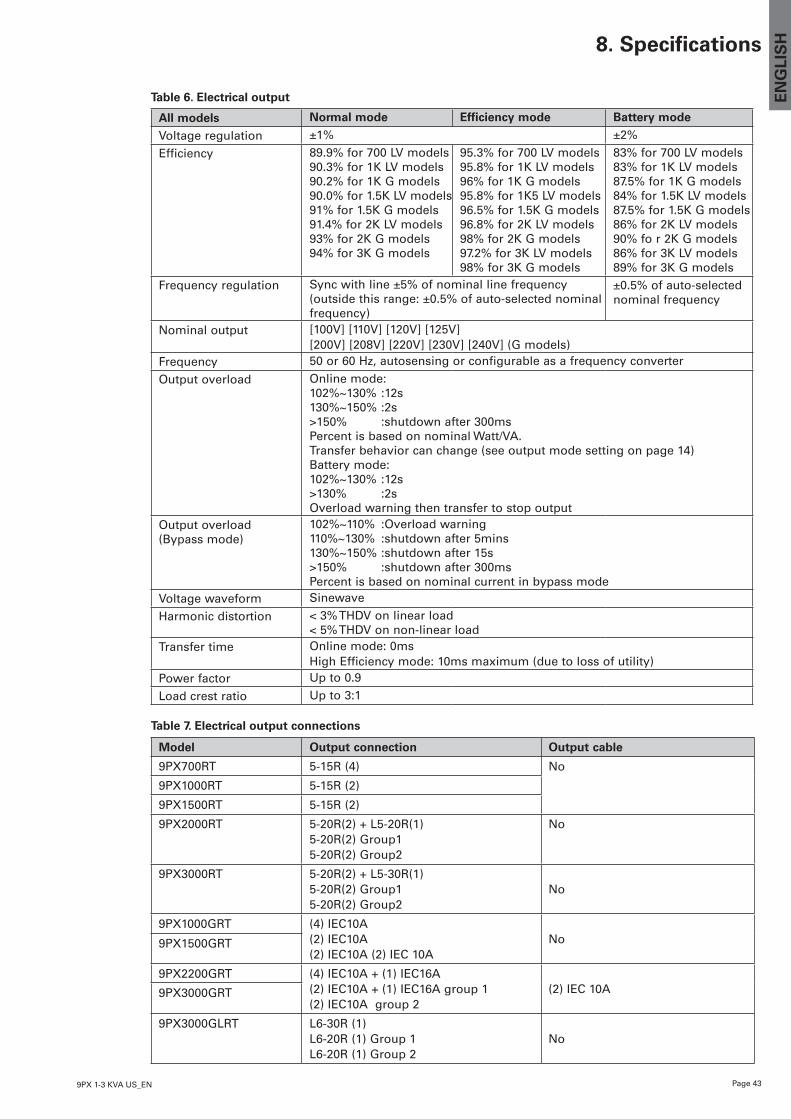
Table 6. Electrical output
All models Normal mode Efficiency mode Battery mode
Voltage regulation ±1% ±2%
Efficiency 89.9% for 700 LV models90.3% for 1K LV models90.2% for 1K G models90.0% for 1.5K LV models91% for 1.5K G models91.4% for 2K LV models93% for 2K G models94% for 3K G models
95.3% for 700 LV models95.8% for 1K LV models96% for 1K G models95.8% for 1K5 LV models96.5% for 1.5K G models96.8% for 2K LV models98% for 2K G models97.2% for 3K LV models98% for 3K G models
83% for 700 LV models83% for 1K LV models87.5% for 1K G models84% for 1.5K LV models87.5% for 1.5K G models86% for 2K LV models90% fo r 2K G models86% for 3K LV models89% for 3K G models
Frequency regulation Sync with line ±5% of nominal line frequency (outside this range: ±0.5% of auto-selected nominal frequency)
±0.5% of auto-selected nominal frequency
Nominal output [100V] [110V] [120V] [125V][200V] [208V] [220V] [230V] [240V] (G models)
Frequency 50 or 60 Hz, autosensing or configurable as a frequency converter
Output overload Online mode:102%~130% :12s130%~150% :2s>150% :shutdown after 300msPercent is based on nominal Watt/VA.Transfer behavior can change (see output mode setting on page 14)Battery mode:102%~130% :12s>130% :2sOverload warning then transfer to stop output
Output overload (Bypass mode)
102%~110% :Overload warning110%~130% :shutdown after 5mins130%~150% :shutdown after 15s >150% :shutdown after 300msPercent is based on nominal current in bypass mode
Voltage waveform Sinewave
Harmonic distortion < 3% THDV on linear load < 5% THDV on non-linear load
Transfer time Online mode: 0ms High Efficiency mode: 10ms maximum (due to loss of utility)
Power factor Up to 0.9
Load crest ratio Up to 3:1
Table 7. Electrical output connections
Model Output connection Output cable
9PX700RT 5-15R (4) No
9PX1000RT 5-15R (2)
9PX1500RT 5-15R (2)
9PX2000RT 5-20R(2) + L5-20R(1)5-20R(2) Group15-20R(2) Group2
No
9PX3000RT 5-20R(2) + L5-30R(1)5-20R(2) Group15-20R(2) Group2
No
9PX1000GRT (4) IEC10A(2) IEC10A(2) IEC10A (2) IEC 10A
No9PX1500GRT
9PX2200GRT (4) IEC10A + (1) IEC16A(2) IEC10A + (1) IEC16A group 1(2) IEC10A group 2
(2) IEC 10A9PX3000GRT
9PX3000GLRT L6-30R (1)L6-20R (1) Group 1L6-20R (1) Group 2
No
Page 44 9PX 1-3 KVA US_EN
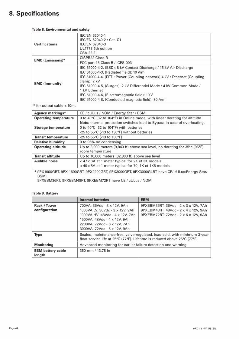
Table 8. Environmental and safety
Certifications
IEC/EN 62040-1 IEC/EN 62040-2 : Cat. C1 IEC/EN 62040-3 UL1778 5th edition CSA 22.2
EMC (Emissions)*CISPR22 Class BFCC part 15 Class B / ICES-003
EMC (Immunity)
IEC 61000-4-2, (ESD): 8 kV Contact Discharge / 15 kV Air DischargeIEC 61000-4-3, (Radiated field): 10 V/mIEC 61000-4-4, (EFT): Power (Coupling network) 4 kV / Ethernet (Coupling clamp) 2 kVIEC 61000-4-5, (Surges): 2 kV Differentiel Mode / 4 kV Common Mode / 1 kV EthernetIEC 61000-4-6, (Electromagnetic field): 10 VIEC 61000-4-8, (Conducted magnetic field): 30 A/m
* for output cable < 10m.
Agency markings* CE / cULus / NOM / Energy Star / BSMIOperating temperature 0 to 40°C (32 to 104°F) in Online mode, with linear derating for altitude
Note: thermal protection switches load to Bypass in case of overheating.Storage temperature 0 to 40°C (32 to 104°F) with batteries
-25 to 55°C (-13 to 130°F) without batteriesTransit temperature -25 to 55°C (-13 to 130°F)Relative humidity 0 to 96% no condensingOperating altitude Up to 3,000 meters (9,843 ft) above sea level, no derating for 35°c (95°F)
room temperatureTransit altitude Up to 10,000 meters (32,808 ft) above sea levelAudible noise < 47 dBA at 1 meter typical for 2K et 3K models
< 40 dBA at 1 meter typical for 70, 1K et 1K5 models
* 9PX1000GRT, 9PX 1500GRT, 9PX2200GRT, 9PX3000GRT, 9PX3000GLRT have CE/ cULus/Energy Star/BSMI. 9PXEBM36RT, 9PXEBM48RT, 9PXEBM72RT have CE / cULus / NOM.
Table 9. Battery
Internal batteries EBM
Rack / Tower configuration
700VA: 36Vdc - 3 x 12V, 9Ah1000VA LV: 36Vdc - 3 x 12V, 9Ah1000VA HV :48Vdc - 4 x 12V, 7Ah1500VA: 48Vdc - 4 x 12V, 9Ah2200VA: 72Vdc - 6 x 12V, 7Ah3000VA: 72Vdc - 6 x 12V, 9Ah
9PXEBM36RT: 36Vdc - 2 x 3 x 12V, 7Ah9PXEBM48RT: 48Vdc - 2 x 4 x 12V, 9Ah9PXEBM72RT: 72Vdc - 2 x 6 x 12V, 9Ah
Type Sealed, maintenance-free, valve-regulated, lead-acid, with minimum 3-year float service life at 25°C (77°F). Lifetime is reduced above 25°C (77°F).
Monitoring Advanced monitoring for earlier failure detection and warning
EBM battery cable length
350 mm / 13.78 in
8. Specifications
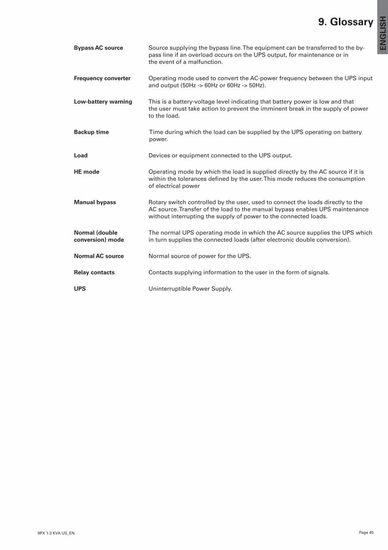
Page 459PX 1-3 KVA US_EN
EN
GLI
SH9. Glossary
Bypass AC source Source supplying the bypass line. The equipment can be transferred to the by-pass line if an overload occurs on the UPS output, for maintenance or in the event of a malfunction.
Frequency converter Operating mode used to convert the AC-power frequency between the UPS input and output (50Hz -> 60Hz or 60Hz -> 50Hz).
Low-battery warning This is a battery-voltage level indicating that battery power is low and that the user must take action to prevent the imminent break in the supply of power to the load.
Backup time Time during which the load can be supplied by the UPS operating on battery power.
Load Devices or equipment connected to the UPS output.
HE mode Operating mode by which the load is supplied directly by the AC source if it is withinthetolerancesdefinedbytheuser.Thismodereducestheconsumption of electrical power
Manual bypass Rotary switch controlled by the user, used to connect the loads directly to the AC source. Transfer of the load to the manual bypass enables UPS maintenance without interrupting the supply of power to the connected loads.
Normal (double The normal UPS operating mode in which the AC source supplies the UPS which conversion) mode in turn supplies the connected loads (after electronic double conversion).
Normal AC source Normal source of power for the UPS.
Relay contacts Contacts supplying information to the user in the form of signals.
UPS Uninterruptible Power Supply.

Page 46 9PX 1-3 KVA US_EN