Embed Size (px)
Citation preview
This document is provided for information purposes. Whilst every effort has been made to provide accurate information, no responsibility is taken for errors or omissions. EUTELSAT reserves the right to change this information without notice.
Organisation européenne de télécommunications par satelliteEuropean Telecommunications Satellite Organization70, rue Balard — 75502 PARIS Cedex 15 — France
February 25, 1998
Digital Satellite Equipment Control (DiSEqC™ )
UPDATE AND
RECOMMENDATIONS FOR
IMPLEMENTATION
VERSION 2.1
page II February 25, 1998 IMPLEM21.TIT
Update and Recommendations for Implementation Version 2.1
Digital Satellite Equipment Control (DiSEqC )
Reference Documents that define the DiSEqC System:
DiSEqC™ Bus Specification Version 4.2 (February 25, 1998)
DiSEqC™ Slave Microcontroller Specification Version 1.0 (February 25, 1998)
DiSEqC™ Logos and Their Conditions of Use (February 25, 1998)
Associated Documents:
Update and Recommendations for Implementation Version 2.1 (February 25, 1998)
Application Information for using a "PIC" Microcontroller in DiSEqC™ LNB andsimple switcher Applications Version 1.0 (June 7, 1999)
Application Information for Tuner-Receiver/IRDs (April 12, 1996)
Application Information for LNBs and Switchers Version 2 (February 25, 1998)
Reset Circuits for the Slave Microcontroller (August 12, 1996)
Simple Tone Burst Detection Circuit (August 12, 1996)
Positioner Application Note Version 1.0 (March 15, 1998)
CONTENTS
page III February 25, 1998 IMPLEM21.TDM
Update and Recommendations for Implementation Version 2.1
Digital Satellite Equipment Control (DiSEqC™ )
1. Introduction . . . . . . . . . . . . . . . . . . . . . . . . . . . . . . . . . . . . . . . . . . . . . . . . . 1
2. Simple Tone Burst DiSEqC Commands . . . . . . . . . . . . . . . . . . . . . . . . . 1
3. Definitions of DiSEqC Levels of Implementation . . . . . . . . . . . . . . . . . 23.1. Proposed Levels of Implementation for Receivers. . . . . . . . . . . . . . . . 43.2. Proposed Levels of Implementation for Accessories . . . . . . . . . . . . . . 5
4. Recommended Implementation for Receivers. . . . . . . . . . . . . . . . . . . . . . 54.1. One-way DiSEqC . . . . . . . . . . . . . . . . . . . . . . . . . . . . . . . . . . . . . . . 5
4.1.1. Recommended sequence of commands for one-way DiSEqC 1.0 . . 64.1.2. Command Structure DiSEqC Level 1.0 . . . . . . . . . . . . . . . . . . . . . . . 7
4.2. Enhanced one-way DiSEqC . . . . . . . . . . . . . . . . . . . . . . . . . . . . . . . 74.2.1.Recommended sequence of commands for enhanced one-way DiSEqC 1.1 . . . . . . . . . . . . . . . . . . . . . . . . . . . . . . . . . . . . . . . . . . . . . . . . . . . . . . . . . . 74.2.2. Repeated DiSEqC Messages . . . . . . . . . . . . . . . . . . . . . . . . . . . . . . . 84.2.3. Recommended sequence of commands for double repeated messages 94.2.4. Remote Tuning . . . . . . . . . . . . . . . . . . . . . . . . . . . . . . . . . . . . . . . . . . . 94.2.5. Transmission of the desired transponder frequency . . . . . . . . . . . . . . 104.2.6. Full sequence of commands in Remote Tuning SMATV mode . . . . 114.2.7. Command Structure for DiSEqC Level 1.1 . . . . . . . . . . . . . . . . . . 114.2.8. Setup Menu for DiSEqC level 1.1. . . . . . . . . . . . . . . . . . . . . . . . . . 124.2.9. DiSEqC Level 1.2 for Positioners . . . . . . . . . . . . . . . . . . . . . . . . . . 12
4.3. Two-way DiSEqC . . . . . . . . . . . . . . . . . . . . . . . . . . . . . . . . . . . . . . 13
5. Implementation for Accessories . . . . . . . . . . . . . . . . . . . . . . . . . . . . . . . . 145.1. Detection of Tone Burst commands using an analogue circuit . . . . . 145.2. Detection using the Slave IC . . . . . . . . . . . . . . . . . . . . . . . . . . . . . . . 14
5.2.1. Dual Functionality of continuous 22 kHz signal . . . . . . . . . . . . . . . . 155.2.2. Decode (de-multiplex) Mode . . . . . . . . . . . . . . . . . . . . . . . . . . . . . . . 16
6. Trade Mark and Self-Certification. . . . . . . . . . . . . . . . . . . . . . . . . . . . . . 176.1. DiSEqC Logo . . . . . . . . . . . . . . . . . . . . . . . . . . . . . . . . . . . . . . . . . 176.2. Test Tool . . . . . . . . . . . . . . . . . . . . . . . . . . . . . . . . . . . . . . . . . . . . . . . 18
7. Reset Procedure . . . . . . . . . . . . . . . . . . . . . . . . . . . . . . . . . . . . . . . . . . . . . 187.1. IF Loop-Through . . . . . . . . . . . . . . . . . . . . . . . . . . . . . . . . . . . . . . . . 18
8. Contact details . . . . . . . . . . . . . . . . . . . . . . . . . . . . . . . . . . . . . . . . . . . . . . 21
Annex A. Common configurations for one-way DiSEqC . . . . . . . . . . . . . . . . . . . 22
Annex B. Progress of CENELEC Standardisation . . . . . . . . . . . . . . . . . . . . . . . . . 27B.1. Current status . . . . . . . . . . . . . . . . . . . . . . . . . . . . . . . . . . . . . . . . . . . 27B.2. Summary of prA11 of EN 61319-1 . . . . . . . . . . . . . . . . . . . . . . . . . . 27
page 1 February 25, 1998 Implem21.frm
Update and Recommendations for Implementation Version 2.1
Digital Satellite Equipment Control (DiSEqC )
1. Introduction
This document describes the recommended implementation of the DiSEqCBus Specification in certain defined configurations and applications. It doesNOT replace the Bus Specification, and in case of inconsistencies between thetwo documents, the Bus Specification takes priority and is always thereference document. These recommendations are only intended to serve as aguide to manufacturers and should not be considered as restricting theapplication of DiSEqC in any way. This document, version 2.1,concentrates on “Enhanced” one-way DiSEqC (Level 1.1) which extendsthe range of applications that can be supported with one-way communication.In particular the need to repeat DiSEqC messages where switches are“cascaded”, to offer more switching states as well as supporting remotefrequency tuning. The equivalent level in two-way DiSEqC is also defined.One-way positioner commands are also introduced and a new level 1.2defined.
At this time with the first generation of DiSEqC products already in themarket it is also necessary to plan the move to full DiSEqC and to drop theold switching protocols (namely the 13/17V) to fully realise the potential costsavings at a system level. It is likely, therefore that DiSEqC only productswill emerge by the end of this year. This will mean that the need for repeatedmessages is increasingly important to support non-backwards compatibleDiSEqC devices, LNBs for example.
2. Simple Tone Burst DiSEqC Commands
The DiSEqC specification includes some extra commands that have beendesigned to be detected by a cheaper analogue circuit in the case of a simpletwo-state switch. In this type of application (see Figure 11: “DiSEqC‰Compatible” switch, page 22), where the slave IC would not be used toprovide any additional functionality (such as 13/17V detection, continuous 22kHz detection etc.) it is reasonable to find the lowest possible cost solution.To allow for these applications tone burst commands are defined asalternatives to the DiSEqC commands for the Satellite Position switch.
These simple commands should be viewed as an extension to the DiSEqCcommand set to allow for cost-reduced, simple two-state analogue switchesand to avoid the unnecessary proliferation of other simple propriety protocols
page 2 February 25, 1998 Implem21.frm
Update and Recommendations for Implementation Version 2.1
Digital Satellite Equipment Control (DiSEqC )
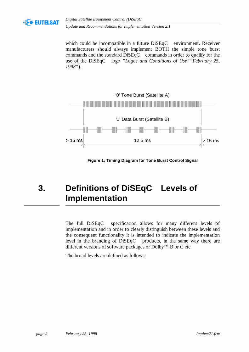
which could be incompatible in a future DiSEqC environment. Receivermanufacturers should always implement BOTH the simple tone burstcommands and the standard DiSEqC commands in order to qualify for theuse of the DiSEqC logo ”Logos and Conditions of Use“”February 25,1998“).
Figure 1: Timing Diagram for Tone Burst Control Signal
3. Definitions of DiSEqC Levels of Implementation
The full DiSEqC specification allows for many different levels ofimplementation and in order to clearly distinguish between these levels andthe consequent functionality it is intended to indicate the implementationlevel in the branding of DiSEqC products, in the same way there aredifferent versions of software packages or Dolby™ B or C etc.
The broad levels are defined as follows:
‘0’ Tone Burst (Satellite A)
‘1’ Data Burst (Satellite B)
12.5 ms> 15 ms> 15 ms > 15 ms
page 3 February 25, 1998 Implem21.frm
Update and Recommendations for Implementation Version 2.1
Digital Satellite Equipment Control (DiSEqC )
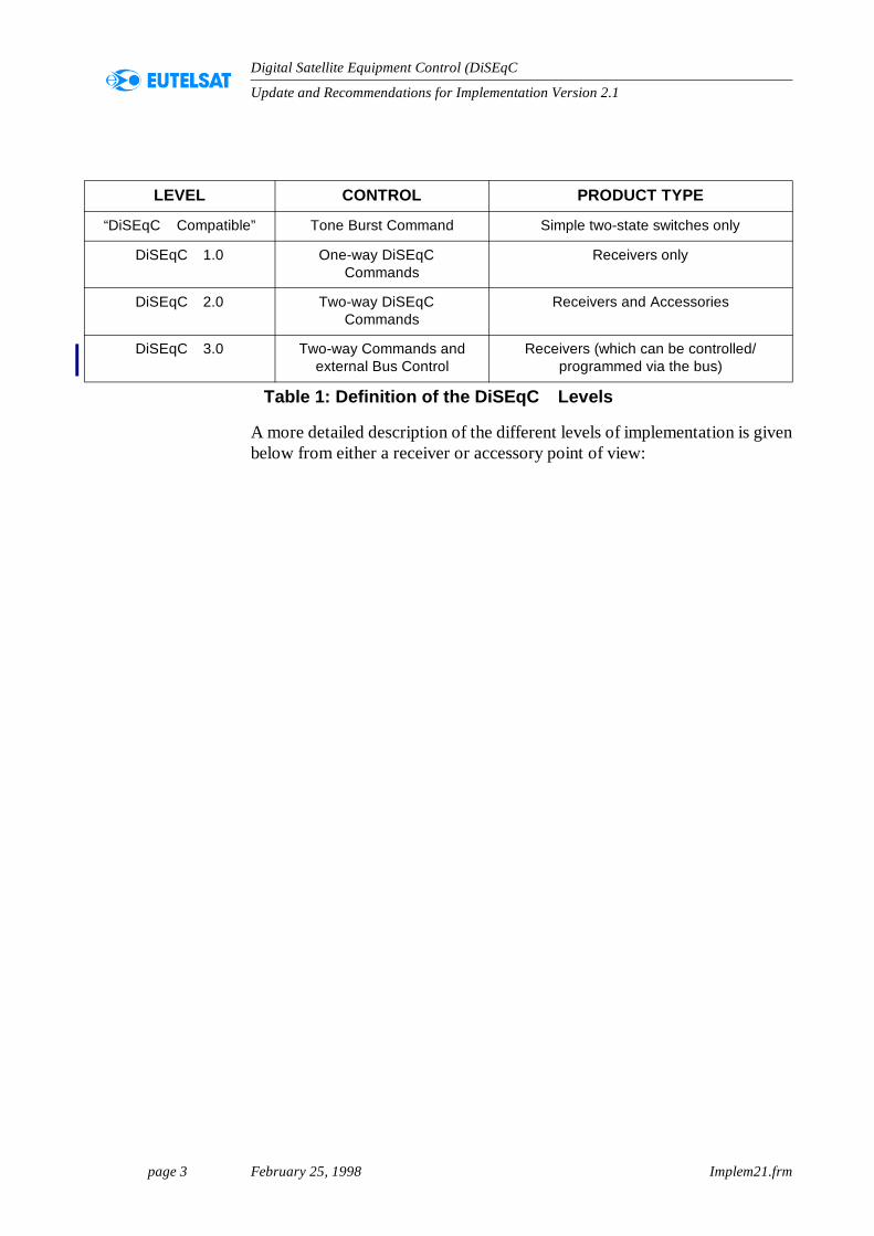
A more detailed description of the different levels of implementation is givenbelow from either a receiver or accessory point of view:
LEVEL CONTROL PRODUCT TYPE
“DiSEqC Compatible” Tone Burst Command Simple two-state switches only
DiSEqC 1.0 One-way DiSEqC Commands
Receivers only
DiSEqC 2.0 Two-way DiSEqC Commands
Receivers and Accessories
DiSEqC 3.0 Two-way Commands and external Bus Control
Receivers (which can be controlled/programmed via the bus)
Table 1: Definition of the DiSEqC Levels
page 4 February 25, 1998 Implem21.frm
Update and Recommendations for Implementation Version 2.1
Digital Satellite Equipment Control (DiSEqC )
3.1. Proposed Levels of Implementation for Receivers
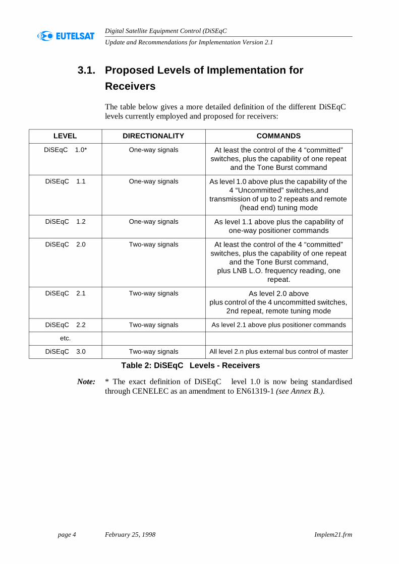
The table below gives a more detailed definition of the different DiSEqClevels currently employed and proposed for receivers:
Note: * The exact definition of DiSEqC level 1.0 is now being standardisedthrough CENELEC as an amendment to EN61319-1 (see Annex B.).
LEVEL DIRECTIONALITY COMMANDS
DiSEqC 1.0* One-way signals At least the control of the 4 “committed” switches, plus the capability of one repeat
and the Tone Burst command
DiSEqC 1.1 One-way signals As level 1.0 above plus the capability of the 4 “Uncommitted” switches,and
transmission of up to 2 repeats and remote (head end) tuning mode
DiSEqC 1.2 One-way signals As level 1.1 above plus the capability of one-way positioner commands
DiSEqC 2.0 Two-way signals At least the control of the 4 “committed” switches, plus the capability of one repeat
and the Tone Burst command,plus LNB L.O. frequency reading, one
repeat.
DiSEqC 2.1 Two-way signals As level 2.0 aboveplus control of the 4 uncommitted switches,
2nd repeat, remote tuning mode
DiSEqC 2.2 Two-way signals As level 2.1 above plus positioner commands
etc.
DiSEqC 3.0 Two-way signals All level 2.n plus external bus control of master
Table 2: DiSEqC Levels - Receivers
page 5 February 25, 1998 Implem21.frm
Update and Recommendations for Implementation Version 2.1
Digital Satellite Equipment Control (DiSEqC )
3.2. Proposed Levels of Implementation for Accessories
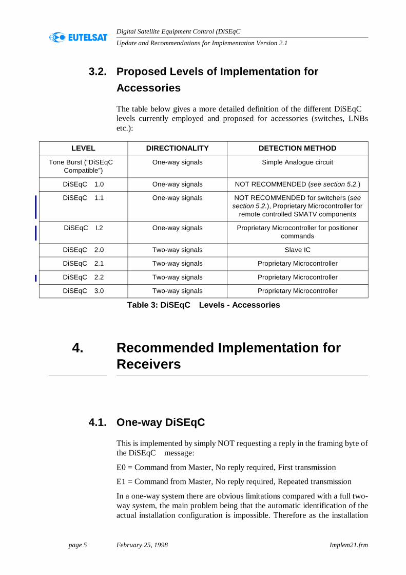
The table below gives a more detailed definition of the different DiSEqClevels currently employed and proposed for accessories (switches, LNBsetc.):
4. Recommended Implementation for Receivers
4.1. One-way DiSEqC
This is implemented by simply NOT requesting a reply in the framing byte ofthe DiSEqC message:
E0 = Command from Master, No reply required, First transmission
E1 = Command from Master, No reply required, Repeated transmission
In a one-way system there are obvious limitations compared with a full two-way system, the main problem being that the automatic identification of theactual installation configuration is impossible. Therefore as the installation
LEVEL DIRECTIONALITY DETECTION METHOD
Tone Burst (“DiSEqC Compatible”)
One-way signals Simple Analogue circuit
DiSEqC 1.0 One-way signals NOT RECOMMENDED (see section 5.2.)
DiSEqC 1.1 One-way signals NOT RECOMMENDED for switchers (see section 5.2.), Proprietary Microcontroller for
remote controlled SMATV components
DiSEqC I.2 One-way signals Proprietary Microcontroller for positioner commands
DiSEqC 2.0 Two-way signals Slave IC
DiSEqC 2.1 Two-way signals Proprietary Microcontroller
DiSEqC 2.2 Two-way signals Proprietary Microcontroller
DiSEqC 3.0 Two-way signals Proprietary Microcontroller
Table 3: DiSEqC Levels - Accessories
page 6 February 25, 1998 Implem21.frm
Update and Recommendations for Implementation Version 2.1
Digital Satellite Equipment Control (DiSEqC )
configurations become more complex (e.g. three or four LNB/IF inputs) thenecessary “links” within the receiver software become more complicated andyet still require a reasonable level of understanding from the installer or userduring installation. In a two-way system, with self-interrogation of the bus, itis possible to tailor the menus according to the devices found on the bus andeven allow, automatically, for differences in local oscillators (assumingDiSEqC LNBs are used).
Therefore, in one-way applications, to ensure compatibility between differentmanufacturers’ equipment and to limit the complexity of the receiver softwarewe suggest that only a limited number of “common” installationconfigurations are to be supported (see Annex A.) in terms of pre-programmedsoftware in the receiver. Of course even one-way DiSEqC allows for manyother types of installations but these other configurations will require a higherlevel of understanding from the installer and possibly re-programming of thereceiver as required. To accommodate the “Enhanced” one-way DiSEqC itwould be advisable to have a DiSEqC installation menu where the differentfeatures can be selected by the user/installer (see later).
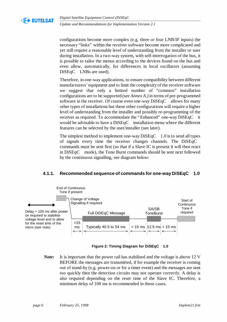
The simplest method to implement one-way DiSEqC 1.0 is to send all typesof signals every time the receiver changes channels. The DiSEqCcommands must be sent first (so that if a Slave IC is present it will then reactin DiSEqC mode), the Tone Burst commands should be sent next followedby the continuous signalling, see diagram below:
4.1.1. Recommended sequence of commands for one-way DiSEqC 1.0
Figure 2: Timing Diagram for DiSEqC 1.0
Note: It is important that the power rail has stabilised and the voltage is above 12 VBEFORE the messages are transmitted, if for example the receiver is comingout of stand-by (e.g. power-on or for a timer event) and the messages are senttoo quickly then the detection circuits may not operate correctly. A delay isalso required depending on the reset time of the Slave IC. Therefore, aminimum delay of 100 ms is recommended in these cases.
End of ContinuousTone if present
Full DiSEqC MessageSA/SB
ToneBurst
Start ofContinuous
Tone ifrequired
Typically 40.5 to 54 ms>15ms > 15 ms> 15 ms 12.5 ms
Change of VoltageSignalling if required
Delay > 100 ms after poweron required to stabilisevoltage level and to allowfor the reset time of themicro (see note)
page 7 February 25, 1998 Implem21.frm
Update and Recommendations for Implementation Version 2.1
Digital Satellite Equipment Control (DiSEqC )
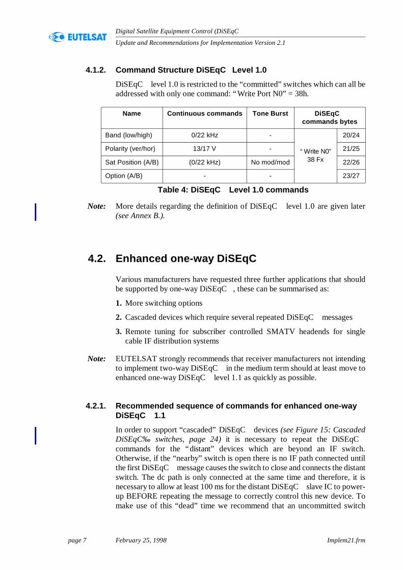
4.1.2. Command Structure DiSEqC Level 1.0
DiSEqC level 1.0 is restricted to the “committed” switches which can all beaddressed with only one command: “Write Port N0” = 38h.
Note: More details regarding the definition of DiSEqC level 1.0 are given later(see Annex B.).
4.2. Enhanced one-way DiSEqC
Various manufacturers have requested three further applications that shouldbe supported by one-way DiSEqC , these can be summarised as:
1. More switching options
2. Cascaded devices which require several repeated DiSEqC messages
3. Remote tuning for subscriber controlled SMATV headends for singlecable IF distribution systems
Note: EUTELSAT strongly recommends that receiver manufacturers not intendingto implement two-way DiSEqC in the medium term should at least move toenhanced one-way DiSEqC level 1.1 as quickly as possible.
4.2.1. Recommended sequence of commands for enhanced one-way DiSEqC 1.1
In order to support “cascaded” DiSEqC devices (see Figure 15: CascadedDiSEqC‰ switches, page 24) it is necessary to repeat the DiSEqCcommands for the “distant” devices which are beyond an IF switch.Otherwise, if the “nearby” switch is open there is no IF path connected untilthe first DiSEqC message causes the switch to close and connects the distantswitch. The dc path is only connected at the same time and therefore, it isnecessary to allow at least 100 ms for the distant DiSEqC slave IC to power-up BEFORE repeating the message to correctly control this new device. Tomake use of this “dead” time we recommend that an uncommitted switch
Name Continuous commands Tone Burst DiSEqC commands bytes
Band (low/high) 0/22 kHz -
“Write N0”38 Fx
20/24
Polarity (ver/hor) 13/17 V - 21/25
Sat Position (A/B) (0/22 kHz) No mod/mod 22/26
Option (A/B) - - 23/27
Table 4: DiSEqC Level 1.0 commands
page 8 February 25, 1998 Implem21.frm
Update and Recommendations for Implementation Version 2.1
Digital Satellite Equipment Control (DiSEqC )
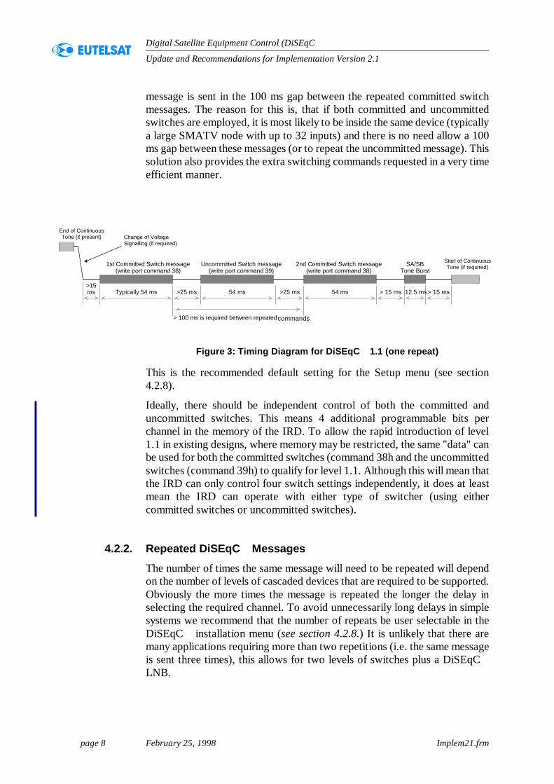
message is sent in the 100 ms gap between the repeated committed switchmessages. The reason for this is, that if both committed and uncommittedswitches are employed, it is most likely to be inside the same device (typicallya large SMATV node with up to 32 inputs) and there is no need allow a 100ms gap between these messages (or to repeat the uncommitted message). Thissolution also provides the extra switching commands requested in a very timeefficient manner.
Figure 3: Timing Diagram for DiSEqC 1.1 (one repeat)
This is the recommended default setting for the Setup menu (see section4.2.8).
Ideally, there should be independent control of both the committed anduncommitted switches. This means 4 additional programmable bits perchannel in the memory of the IRD. To allow the rapid introduction of level1.1 in existing designs, where memory may be restricted, the same "data" canbe used for both the committed switches (command 38h and the uncommittedswitches (command 39h) to qualify for level 1.1. Although this will mean thatthe IRD can only control four switch settings independently, it does at leastmean the IRD can operate with either type of switcher (using eithercommitted switches or uncommitted switches).
4.2.2. Repeated DiSEqC Messages
The number of times the same message will need to be repeated will dependon the number of levels of cascaded devices that are required to be supported.Obviously the more times the message is repeated the longer the delay inselecting the required channel. To avoid unnecessarily long delays in simplesystems we recommend that the number of repeats be user selectable in theDiSEqC installation menu (see section 4.2.8.) It is unlikely that there aremany applications requiring more than two repetitions (i.e. the same messageis sent three times), this allows for two levels of switches plus a DiSEqCLNB.
End of ContinuousTone (if present)
SA/SBTone Burst
Start of ContinuousTone (if required)
> 15 ms> 15 ms 12.5 ms
1st Committed Switch message(write port command 38)
Typically 54 ms>15ms
Change of VoltageSignalling (if required)
Uncommitted Switch message(write port command 39)
54 ms>25 ms 54 ms>25 ms
2nd Committed Switch message(write port command 38)
> 100 ms is required between repeatedcommands
commands
page 9 February 25, 1998 Implem21.frm
Update and Recommendations for Implementation Version 2.1
Digital Satellite Equipment Control (DiSEqC )
Note: In a two-way system the receiver can interrogate the bus to establish the exactconfiguration and automatically select the required number of repeats.
Note: The Tone Burst signal must always be at the end of the message, AFTER thelast repeated DiSEqC command. Therefore, if a Tone-Burst switch is used,it MUST be farthest from the receiver to operate correctly.
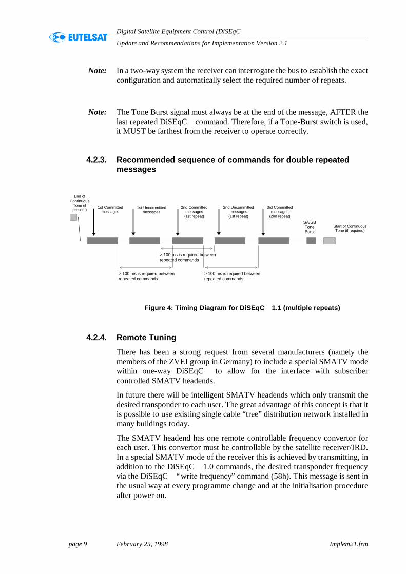
4.2.3. Recommended sequence of commands for double repeated messages
Figure 4: Timing Diagram for DiSEqC 1.1 (multiple repeats)
4.2.4. Remote Tuning
There has been a strong request from several manufacturers (namely themembers of the ZVEI group in Germany) to include a special SMATV modewithin one-way DiSEqC to allow for the interface with subscribercontrolled SMATV headends.
In future there will be intelligent SMATV headends which only transmit thedesired transponder to each user. The great advantage of this concept is that itis possible to use existing single cable “tree” distribution network installed inmany buildings today.
The SMATV headend has one remote controllable frequency convertor foreach user. This convertor must be controllable by the satellite receiver/IRD.In a special SMATV mode of the receiver this is achieved by transmitting, inaddition to the DiSEqC 1.0 commands, the desired transponder frequencyvia the DiSEqC “write frequency” command (58h). This message is sent inthe usual way at every programme change and at the initialisation procedureafter power on.
End ofContinuous
Tone (ifpresent)
SA/SBToneBurst
Start of ContinuousTone (if required)
> 100 ms is required betweenrepeated commands
> 100 ms is required betweenrepeated commands
1st Committedmessages
1st Uncommittedmessages
2nd Committedmessages
(1st repeat)
2nd Uncommittedmessages
(1st repeat)
3rd Committedmessages
(2nd repeat)
> 100 ms is required betweenrepeated commands
page 10 February 25, 1998 Implem21.frm
Update and Recommendations for Implementation Version 2.1
Digital Satellite Equipment Control (DiSEqC )
It is important to understand that the DiSEqC signals are simply used as an“open interface” for the data transmission from the satellite receiver to apropriety modem located between the receiver and the wall outlet (see Figure19: Subscriber controlled SMATV Headend, page 26). The modem convertsthe DiSEqC commands to a suitable propriety bus format (typically a fastermulti-master bus) for the transmission to the headend.
In the remote tuning SMATV mode the tuner in the receiver stays fixed on thesubscriber’s individual transmission frequency of the SMATV headend. Theselection of this SMATV mode and the fixed transmission frequency needonly be entered one time during the installation procedure. In this mode theLNB voltage should remained fixed in the low setting (13 V) to minimisepower consumption (the polarisation control is performed via the DiSEqCmessage).
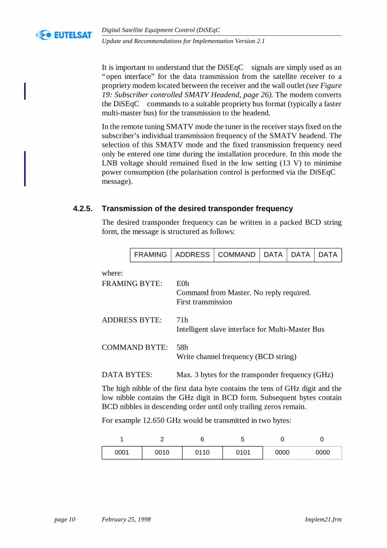
4.2.5. Transmission of the desired transponder frequency
The desired transponder frequency can be written in a packed BCD stringform, the message is structured as follows:
where:FRAMING BYTE: E0h
Command from Master. No reply required.First transmission
ADDRESS BYTE: 71hIntelligent slave interface for Multi-Master Bus
COMMAND BYTE: 58hWrite channel frequency (BCD string)
DATA BYTES: Max. 3 bytes for the transponder frequency (GHz)
The high nibble of the first data byte contains the tens of GHz digit and thelow nibble contains the GHz digit in BCD form. Subsequent bytes containBCD nibbles in descending order until only trailing zeros remain.
For example 12.650 GHz would be transmitted in two bytes:
FRAMING ADDRESS COMMAND DATA DATA DATA
1 2 6 5 0 0
0001 0010 0110 0101 0000 0000
page 11 February 25, 1998 Implem21.frm
Update and Recommendations for Implementation Version 2.1
Digital Satellite Equipment Control (DiSEqC )
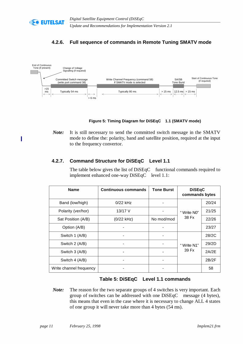
4.2.6. Full sequence of commands in Remote Tuning SMATV mode
Figure 5: Timing Diagram for DiSEqC 1.1 (SMATV mode)
Note: It is still necessary to send the committed switch message in the SMATVmode to define the: polarity, band and satellite position, required at the inputto the frequency convertor.
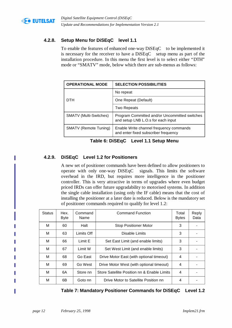
4.2.7. Command Structure for DiSEqC Level 1.1
The table below gives the list of DiSEqC functional commands required toimplement enhanced one-way DiSEqC level 1.1:
Table 5: DiSEqC Level 1.1 commands
Note: The reason for the two separate groups of 4 switches is very important. Eachgroup of switches can be addressed with one DiSEqC message (4 bytes),this means that even in the case where it is necessary to change ALL 4 statesof one group it will never take more than 4 bytes (54 ms).
End of ContinuousTone (if present)
SA/SBTone Burst
Start of Continuous Tone(if required)
> 15 ms> 15 ms 12.5 ms
Committed Switch message(write port command 38)
Typically 54 ms>15ms
Change of VoltageSignalling (if required)
Write Channel Frequency (command 58)If SMATV mode is selected
Typically 80 ms
> 6 ms
Name Continuous commands Tone Burst DiSEqC commands bytes
Band (low/high) 0/22 kHz -
“Write N0”38 Fx
20/24
Polarity (ver/hor) 13/17 V - 21/25
Sat Position (A/B) (0/22 kHz) No mod/mod 22/26
Option (A/B) - - 23/27
Switch 1 (A/B) - -
“Write N1”39 Fx
28/2C
Switch 2 (A/B) - - 29/2D
Switch 3 (A/B) - - 2A/2E
Switch 4 (A/B) - - 2B/2F
Write channel frequency - - 58
page 12 February 25, 1998 Implem21.frm
Update and Recommendations for Implementation Version 2.1
Digital Satellite Equipment Control (DiSEqC )
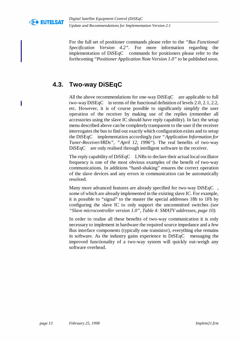
4.2.8. Setup Menu for DiSEqC level 1.1
To enable the features of enhanced one-way DiSEqC to be implemented itis necessary for the receiver to have a DiSEqC setup menu as part of theinstallation procedure. In this menu the first level is to select either “DTH”mode or “SMATV” mode, below which there are sub-menus as follows:
4.2.9. DiSEqC Level 1.2 for Positioners
A new set of positioner commands have been defined to allow positioners tooperate with only one-way DiSEqC signals. This limits the softwareoverhead in the IRD, but requires more intelligence in the positionercontroller. This is very attractive in terms of upgrades where even budgetpriced IRDs can offer future upgradability to motorised systems. In additionthe single cable installation (using only the IF cable) means that the cost ofinstalling the positioner at a later date is reduced. Below is the mandatory setof positioner commands required to qualify for level 1.2:
Table 7: Mandatory Positioner Commands for DiSEqC Level 1.2
OPERATIONAL MODE SELECTION POSSIBILITIES
DTH
No repeat
One Repeat (Default)
Two Repeats
SMATV (Multi-Switches) Program Committed and/or Uncommitted switchesand setup LNB L.O.s for each input
SMATV (Remote Tuning) Enable Write channel frequency commandsand enter fixed subscriber frequency
Table 6: DiSEqC Level 1.1 Setup Menu
Status Hex. Byte
Command Name
Command Function Total Bytes
Reply Data
M 60 Halt Stop Positioner Motor 3 -
M 63 Limits Off Disable Limits 3 -
M 66 Limit E Set East Limit (and enable limits) 3 -
M 67 Limit W Set West Limit (and enable limits) 3 -
M 68 Go East Drive Motor East (with optional timeout) 4 -
M 69 Go West Drive Motor West (with optional timeout) 4 -
M 6A Store nn Store Satellite Position nn & Enable Limits 4 -
M 6B Goto nn Drive Motor to Satellite Position nn 4 -
page 13 February 25, 1998 Implem21.frm
Update and Recommendations for Implementation Version 2.1
Digital Satellite Equipment Control (DiSEqC )
For the full set of positioner commands please refer to the “Bus FunctionalSpecification Version 4.2”. For more information regarding theimplementation of DiSEqC commands for positioners please refer to theforthcoming “Positioner Application Note Version 1.0” to be published soon.
4.3. Two-way DiSEqC
All the above recommendations for one-way DiSEqC are applicable to fulltwo-way DiSEqC in terms of the functional definition of levels 2.0, 2.1, 2.2,etc. However, it is of course possible to significantly simplify the useroperation of the receiver by making use of the replies (remember allaccessories using the slave IC should have reply capability). In fact the setupmenu described above can be completely transparent to the user if the receiverinterrogates the bus to find out exactly which configuration exists and to setupthe DiSEqC implementation accordingly (see “Application Information forTuner-Receiver/IRDs”, ”April 12, 1996“). The real benefits of two-wayDiSEqC are only realised through intelligent software in the receiver.
The reply capability of DiSEqC LNBs to declare their actual local oscillatorfrequency is one of the most obvious examples of the benefit of two-waycommunications. In additions “hand-shaking” ensures the correct operationof the slave devices and any errors in communication can be automaticallyresolved.
Many more advanced features are already specified for two-way DiSEqC ,some of which are already implemented in the existing slave IC. For example,it is possible to “signal” to the master the special addresses 18h to 1Fh byconfiguring the slave IC to only support the uncommitted switches (see“Slave microcontroller version 1.0”, Table 4: SMATV addresses, page 10).
In order to realise all these benefits of two-way communication it is onlynecessary to implement in hardware the required source impedance and a fewBus interface components (typically one transistor), everything else remainsin software. As the industry gains experience in DiSEqC messaging theimproved functionality of a two-way system will quickly out-weigh anysoftware overhead.
page 14 February 25, 1998 Implem21.frm
Update and Recommendations for Implementation Version 2.1
Digital Satellite Equipment Control (DiSEqC )
5. Implementation for Accessories
5.1. Detection of Tone Burst commands using an analogue circuit
The cost advantage of the analogue detection of the Tone Burst is onlyachieved in applications where the Slave IC cannot be used to add anyadditional functionality (see Annex A. Common configurations for one-wayDiSEqC‰ , page 22). Please refer to the document “Simple "ToneBurst"Detection Circuit” for more details, but the exact design will depend on themanufacturer’s own preferred solution.
5.2. Detection using the Slave IC
The advantage of the Slave IC is that in one very cheap microcontroller a largeamount of functionality is included:
1. DiSEqC detection
2. Tone Burst detection
3. 13/17 V and continuous 22 kHz tone detection
4. Reply capability
5. Decode mode
It is STRONGLY recommended that any accessory utilising the Slave ICshould always implement the return path modem (only one transistor) sincetwo-way capability significantly improves the user friendliness of the systemand some receiver manufacturers will start with two-way communication. Ithas been estimated (by a manufacturer) that a typical detection circuit using aSlave IC with all the above functionality (but excluding voltage regulationand PCB space) is approximately 1.1 ECU (i.e. < £1), this replaces the costfor the existing analogue detection circuits.
Note: Accessories using the Slave IC but NOT implementing the return path willNOT be eligible for DiSEqC branding.
page 15 February 25, 1998 Implem21.frm
Update and Recommendations for Implementation Version 2.1
Digital Satellite Equipment Control (DiSEqC )
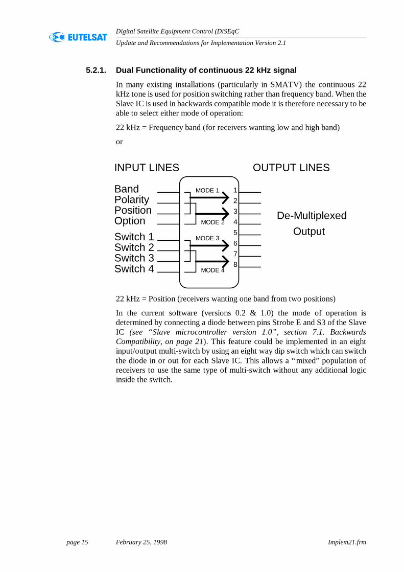
5.2.1. Dual Functionality of continuous 22 kHz signal
In many existing installations (particularly in SMATV) the continuous 22kHz tone is used for position switching rather than frequency band. When theSlave IC is used in backwards compatible mode it is therefore necessary to beable to select either mode of operation:
22 kHz = Frequency band (for receivers wanting low and high band)
or
22 kHz = Position (receivers wanting one band from two positions)
In the current software (versions 0.2 & 1.0) the mode of operation isdetermined by connecting a diode between pins Strobe E and S3 of the SlaveIC (see “Slave microcontroller version 1.0”, section 7.1. BackwardsCompatibility, on page 21). This feature could be implemented in an eightinput/output multi-switch by using an eight way dip switch which can switchthe diode in or out for each Slave IC. This allows a “mixed” population ofreceivers to use the same type of multi-switch without any additional logicinside the switch.
INPUT LINES OUTPUT LINES
BandPolarityPositionOptionSwitch 1Switch 2Switch 3Switch 4
12345678
MODE 1
MODE 2
MODE 3
MODE 4
De-MultiplexedOutput
page 16 February 25, 1998 Implem21.frm
Update and Recommendations for Implementation Version 2.1
Digital Satellite Equipment Control (DiSEqC )
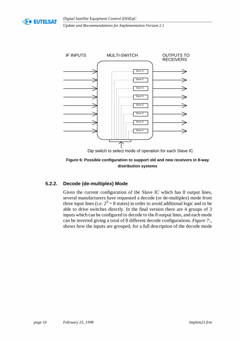
Figure 6: Possible configuration to support old and new receivers in 8-way distribution systems
5.2.2. Decode (de-multiplex) Mode
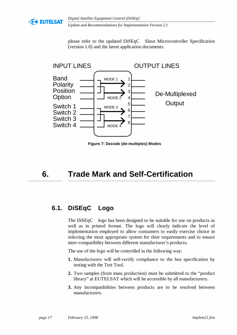
Given the current configuration of the Slave IC which has 8 output lines,several manufacturers have requested a decode (or de-multiplex) mode fromthree input lines (i.e. 23 = 8 states) in order to avoid additional logic and to beable to drive switches directly. In the final version there are 4 groups of 3inputs which can be configured to decode to the 8 output lines, and each modecan be inverted giving a total of 8 different decode configurations. Figure 7:,shows how the inputs are grouped, for a full description of the decode mode
IF INPUTS
Slave IC
Slave IC
Slave IC
Slave IC
Slave IC
Slave IC
Slave IC
Slave IC
Dip switch to select mode of operation for each Slave IC
OUTPUTS TORECEIVERS
MULTI-SWITCH
page 17 February 25, 1998 Implem21.frm
Update and Recommendations for Implementation Version 2.1
Digital Satellite Equipment Control (DiSEqC )
please refer to the updated DiSEqC Slave Microcontroller Specification(version 1.0) and the latest application documents.
6. Trade Mark and Self-Certification
6.1. DiSEqC Logo
The DiSEqC logo has been designed to be suitable for use on products aswell as in printed format. The logo will clearly indicate the level ofimplementation employed to allow consumers to easily exercise choice inselecting the most appropriate system for their requirements and to ensureinter-compatibility between different manufacturer’s products.
The use of the logo will be controlled in the following way:
1. Manufacturers will self-certify compliance to the bus specification bytesting with the Test Tool.
2. Two samples (from mass production) must be submitted to the “productlibrary” at EUTELSAT which will be accessible by all manufacturers.
3. Any incompatibilities between products are to be resolved betweenmanufacturers.
Figure 7: Decode (de-multiplex) Modes
INPUT LINES OUTPUT LINES
BandPolarityPositionOptionSwitch 1Switch 2Switch 3Switch 4
12345678
MODE 1
MODE 2
MODE 3
MODE 4
De-MultiplexedOutput
page 18 February 25, 1998 Implem21.frm
Update and Recommendations for Implementation Version 2.1
Digital Satellite Equipment Control (DiSEqC )
Please refer to the document ”Logos and Conditions of Use“, ”February 25,1998“
6.2. Test Tool
To allow fast development and self-certification, the idea a Test Tool has beendeveloped (based on the original evaluation boards) which allows the preciseperformance of a device to be measured in terms of the bus specification.Revisions to the bus specification would be accompanied by the appropriatechanges (if necessary) to the Test Tool. In order to self-certify compliance tothe bus specification it will be mandatory that manufacturers procure a TestTool for their own use. Owners of evaluation boards are entitled to receiveone of the Test Tools free of charge. For new manufacturers the cost of theTest Tool will be a nominal sum simply to cover the hardware costs, pleasesend enquiries directly to EUTELSAT at the address at the end of thedocument.
7. Reset Procedure
7.1. IF Loop-Through
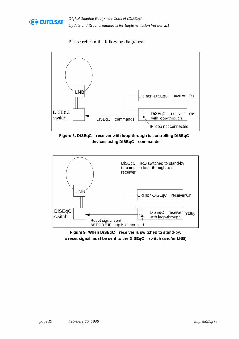
Receivers employing an IF Loop-Through (e.g. digital IRDs with a loop-through for an analogue receiver) MUST include a reset for the Slave ICeach time the IF path is switched. This is to ensure backwardscompatibility with old receivers.
page 19 February 25, 1998 Implem21.frm
Update and Recommendations for Implementation Version 2.1
Digital Satellite Equipment Control (DiSEqC )
Please refer to the following diagrams:
Figure 8: DiSEqC receiver with loop-through is controlling DiSEqC devices using DiSEqC commands
Figure 9: When DiSEqC receiver is switched to stand-by, a reset signal must be sent to the DiSEqC switch (and/or LNB)
LNB
DiSEqCswitch
Old non-DiSEqC
DiSEqC receiverwith loop-throughDiSEqC commands
IF loop not connected
On
Onreceiver
LNB
DiSEqCswitch
Old non-DiSEqC receiver
DiSEqC receiverwith loop-through
Reset signal sentBEFORE IF loop is connected
DiSEqC IRD switched to stand-byto complete loop-through to oldreceiver
Stdby
On
page 20 February 25, 1998 Implem21.frm
Update and Recommendations for Implementation Version 2.1
Digital Satellite Equipment Control (DiSEqC )
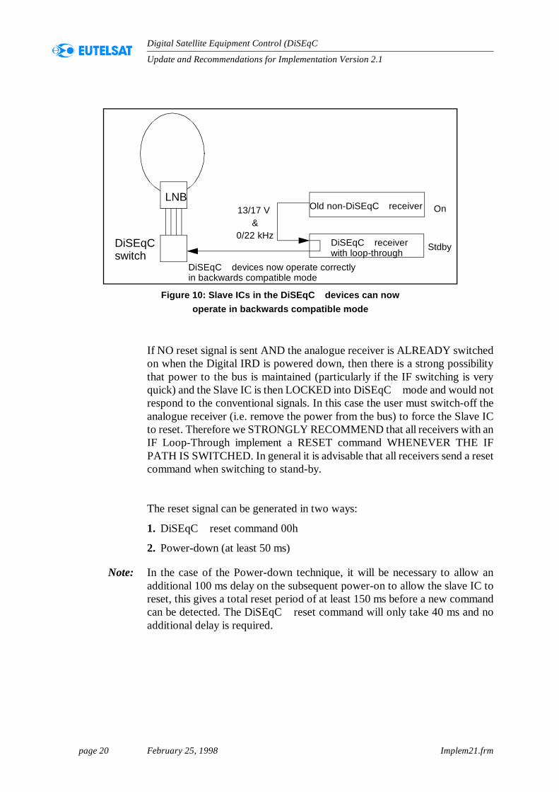
If NO reset signal is sent AND the analogue receiver is ALREADY switchedon when the Digital IRD is powered down, then there is a strong possibilitythat power to the bus is maintained (particularly if the IF switching is veryquick) and the Slave IC is then LOCKED into DiSEqC mode and would notrespond to the conventional signals. In this case the user must switch-off theanalogue receiver (i.e. remove the power from the bus) to force the Slave ICto reset. Therefore we STRONGLY RECOMMEND that all receivers with anIF Loop-Through implement a RESET command WHENEVER THE IFPATH IS SWITCHED. In general it is advisable that all receivers send a resetcommand when switching to stand-by.
The reset signal can be generated in two ways:
1. DiSEqC reset command 00h
2. Power-down (at least 50 ms)
Note: In the case of the Power-down technique, it will be necessary to allow anadditional 100 ms delay on the subsequent power-on to allow the slave IC toreset, this gives a total reset period of at least 150 ms before a new commandcan be detected. The DiSEqC reset command will only take 40 ms and noadditional delay is required.
Figure 10: Slave ICs in the DiSEqC devices can now operate in backwards compatible mode
LNB
DiSEqCswitch
Old non-DiSEqC receiver
DiSEqC receiverwith loop-through
13/17 V &
0/22 kHz
DiSEqC devices now operate correctlyin backwards compatible mode
Stdby
On
page 22 February 25, 1998 Implem21.frm
Update and Recommendations for Implementation Version 2.1
Digital Satellite Equipment Control (DiSEqC )
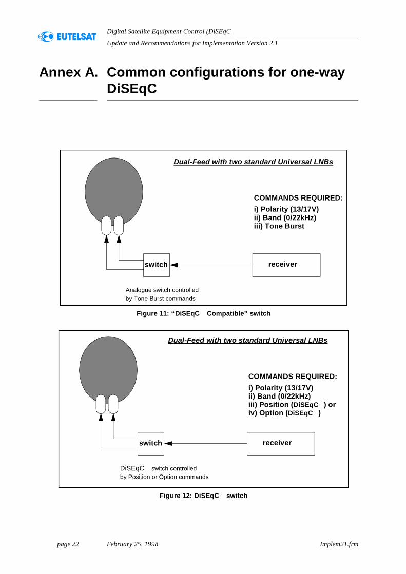
Annex A. Common configurations for one-way DiSEqC
Figure 11: “DiSEqC Compatible” switch
Figure 12: DiSEqC switch
switch receiver
COMMANDS REQUIRED:i) Polarity (13/17V)ii) Band (0/22kHz)iii) Tone Burst
Analogue switch controlledby Tone Burst commands
Dual-Feed with two standard Universal LNBs
switch receiver
COMMANDS REQUIRED:i) Polarity (13/17V)ii) Band (0/22kHz)iii) Position (DiSEqC ) or
DiSEqC switch controlledby Position or Option commands
Dual-Feed with two standard Universal LNBs
iv) Option (DiSEqC )
page 23 February 25, 1998 Implem21.frm
Update and Recommendations for Implementation Version 2.1
Digital Satellite Equipment Control (DiSEqC )
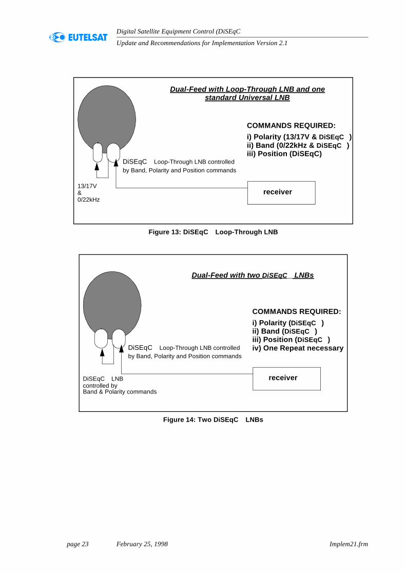
Figure 13: DiSEqC Loop-Through LNB
Figure 14: Two DiSEqC LNBs
receiver
COMMANDS REQUIRED:i) Polarity (13/17V & DiSEqC )ii) Band (0/22kHz & DiSEqC )iii) Position (DiSEqC)
DiSEqC Loop-Through LNB controlledby Band, Polarity and Position commands
Dual-Feed with Loop-Through LNB and onestandard Universal LNB
13/17V&0/22kHz
receiver
COMMANDS REQUIRED:i) Polarity (DiSEqC )ii) Band (DiSEqC )iii) Position (DiSEqC )
DiSEqC Loop-Through LNB controlledby Band, Polarity and Position commands
Dual-Feed with two DiSEqC LNBs
DiSEqC LNBcontrolled by
iv) One Repeat necessary
Band & Polarity commands
page 24 February 25, 1998 Implem21.frm
Update and Recommendations for Implementation Version 2.1
Digital Satellite Equipment Control (DiSEqC )
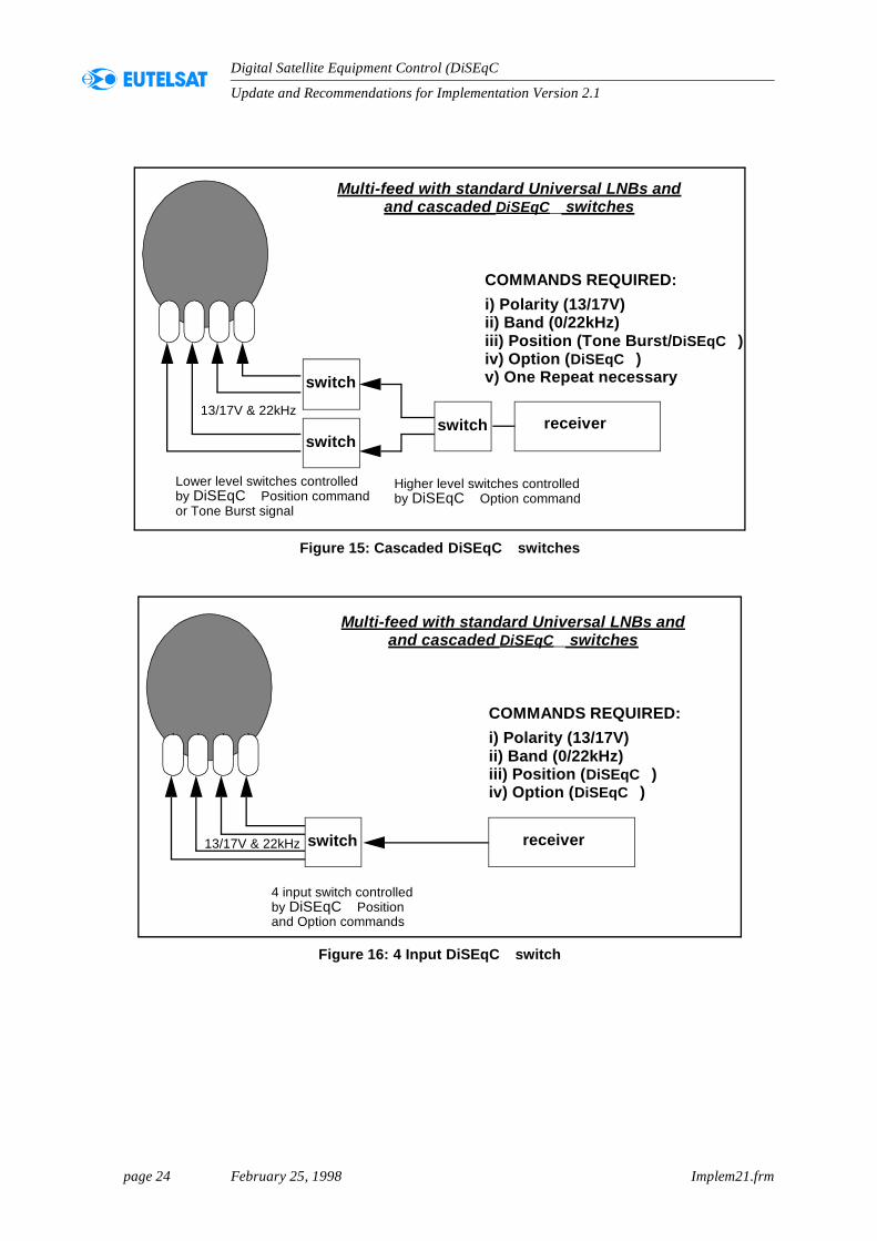
Figure 15: Cascaded DiSEqC switches
Figure 16: 4 Input DiSEqC switch
receiver
COMMANDS REQUIRED:i) Polarity (13/17V)ii) Band (0/22kHz)iii) Position (Tone Burst/DiSEqC )
13/17V & 22kHz
Lower level switches controlled
Multi-feed with standard Universal LNBs andand cascaded DiSEqC switches
iv) Option (DiSEqC )
switch
switch
switch
by DiSEqC Position commandor Tone Burst signal
Higher level switches controlledby DiSEqC Option command
v) One Repeat necessary
receiver
COMMANDS REQUIRED:i) Polarity (13/17V)ii) Band (0/22kHz)iii) Position (DiSEqC )
13/17V & 22kHz
Multi-feed with standard Universal LNBs andand cascaded DiSEqC switches
iv) Option (DiSEqC )
switch
4 input switch controlledby DiSEqC Positionand Option commands
page 25 February 25, 1998 Implem21.frm
Update and Recommendations for Implementation Version 2.1
Digital Satellite Equipment Control (DiSEqC )
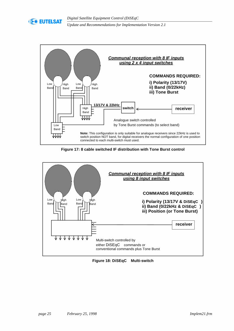
Figure 17: 8 cable switched IF distribution with Tone Burst control
Figure 18: DiSEqC Multi-switch
receiver
Communal reception with 8 IF inputs
LowBand
HighBand
LowBand
HighBand
HighBand
LowBand
switch
Analogue switch controlledby Tone Burst commands (to select band)
COMMANDS REQUIRED:i) Polarity (13/17V)ii) Band (0/22kHz)iii) Tone Burst
using 2 x 4 input switches
13/17V & 22kHz
Note: This configuration is only suitable for analogue receivers since 22kHz is used toswitch position NOT band, for digital receivers the normal configuration of one positionconnected to each multi-switch must used.
receiver
Communal reception with 8 IF inputs
LowBand
HighBand
LowBand
HighBand
Multi-switch controlled byeither DiSEqC commands or
COMMANDS REQUIRED:
using 8 input switches
i) Polarity (13/17V & DiSEqC )ii) Band (0/22kHz & DiSEqC )iii) Position (or Tone Burst)
conventional commands plus Tone Burst
page 26 February 25, 1998 Implem21.frm
Update and Recommendations for Implementation Version 2.1
Digital Satellite Equipment Control (DiSEqC )
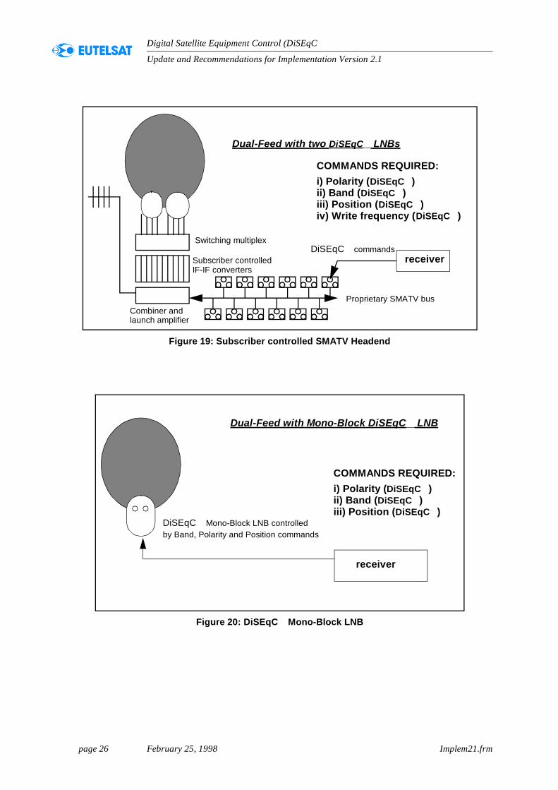
Figure 19: Subscriber controlled SMATV Headend
receiver
COMMANDS REQUIRED:i) Polarity (DiSEqC )ii) Band (DiSEqC )iii) Position (DiSEqC )
Switching multiplex
Subscriber controlled
Dual-Feed with two DiSEqC LNBs
Combiner and
iv) Write frequency (DiSEqC )
launch amplifier
DiSEqC commands
Proprietary SMATV bus
IF-IF converters
Figure 20: DiSEqC Mono-Block LNB
receiver
COMMANDS REQUIRED:i) Polarity (DiSEqC )ii) Band (DiSEqC )iii) Position (DiSEqC )
DiSEqC Mono-Block LNB controlledby Band, Polarity and Position commands
Dual-Feed with Mono-Block DiSEqC LNB
page 27 February 25, 1998 Implem21.frm
Update and Recommendations for Implementation Version 2.1
Digital Satellite Equipment Control (DiSEqC )
Annex B. Progress of CENELEC Standardisation
B.1. Current status
DiSEqC level 1.0 is planned to be incorporated as part of the existingEuropean Norm EN 61319-1 "Interconnection of Satellite ReceivingEquipment".
To this entent, the draft amendment prA11 of EN 61319-1 has been formallyaccepted by the TC 206 committee and has been approved for the UniqueAcceptance Procedure (UAP).
This procedure takes 6 months to complete and is planned to start shortly.
B.2. Summary of prA11 of EN 61319-1
INTRODUCTION
In the first edition of the CLC publication EN 61319-1, the interfaces for the control and command of the
devices associated with the satellite receivers are described in the following clauses:
cl 4:Interface requirements for polarizers and polar switchers
cl 5:Interface requirements for low noise block converters (LNB)
cl 6:Interface requirements for switching between different antenna sources or antenna positions.
In these clauses, analogue techniques are described and in particular the so called “13/18 DC. voltage
and 22 kHz tone” which are extensively used in EUROPE today.
The purpose of this amendment is to introduce a single method of communication, between the satellite
receiver and the peripheral equipment, using only the existing coaxial cable. The method is based on the
specifications of the “Digital Satellite Equipment Control Bus” called DiSEqC . It can replace all
conventional analogue switching and all other control wiring.
It is backwards compatible with 13/18 volt and 22 kHz tone switching.
Interconnection of satellite receiving equipment
Part 1: Europe
Amendment prA11
_____________________
page 28 February 25, 1998 Implem21.frm
Update and Recommendations for Implementation Version 2.1
Digital Satellite Equipment Control (DiSEqC )
SCOPE
This amendment deals with a subset of the DiSEqC Bus used for communications of control and
command messages from the Satellite receiver/IRD to the peripheral equipment. It describes the principle
of the communication method and gives the major requirements for:
-the system structure,
-the message structure and the table of commands,
-the signal characteristics,
-the signal transport conditions.
The following picture gives informative examples of typical configurations in order to show which interface
is covered by the clauses of EN 61319-1 : 1995 and by those of this amendment.
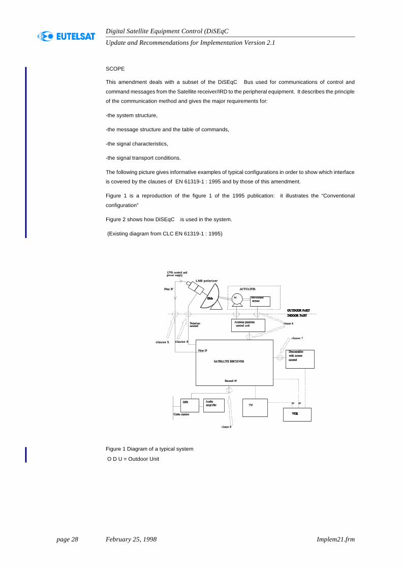
Figure 1 is a reproduction of the figure 1 of the 1995 publication: it illustrates the “Conventional
configuration”
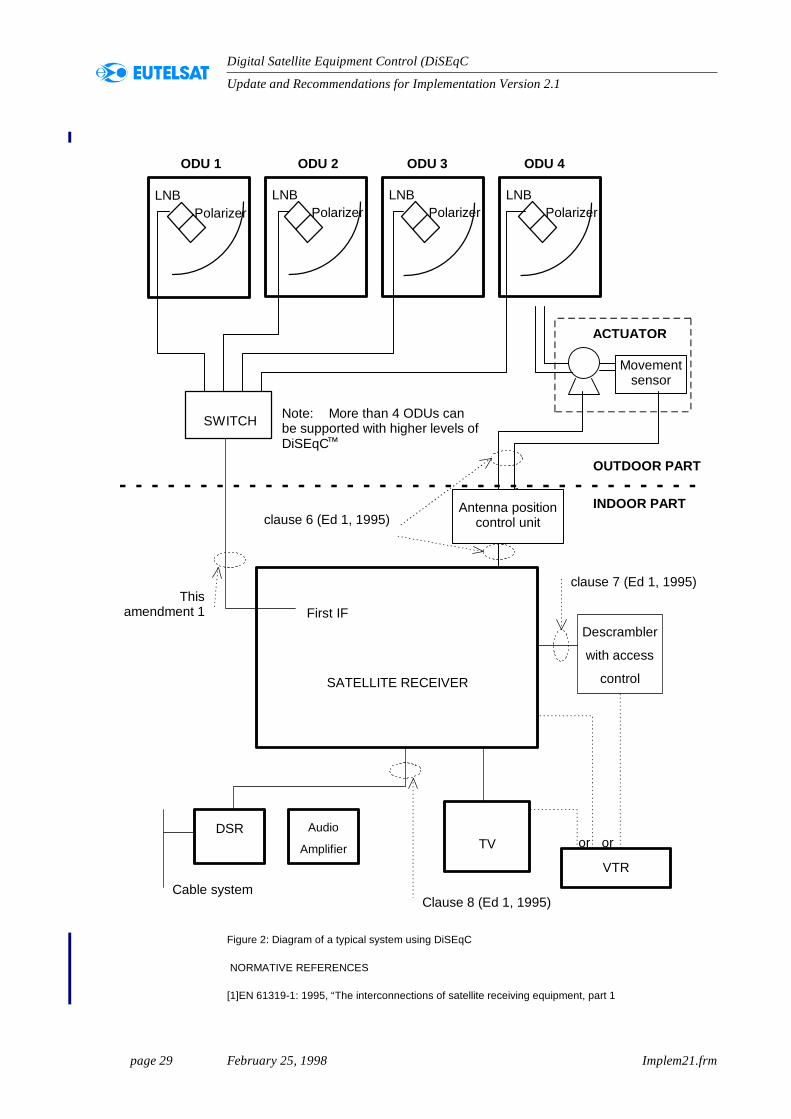
Figure 2 shows how DiSEqC is used in the system.
(Existing diagram from CLC EN 61319-1 : 1995)
Figure 1 Diagram of a typical system
O D U = Outdoor Unit
clause 5 clause 4
LNB polarizer
clause 7
page 29 February 25, 1998 Implem21.frm
Update and Recommendations for Implementation Version 2.1
Digital Satellite Equipment Control (DiSEqC )
Figure 2: Diagram of a typical system using DiSEqC
NORMATIVE REFERENCES
[1]EN 61319-1: 1995, “The interconnections of satellite receiving equipment, part 1
SWITCH
First IF
SATELLITE RECEIVER
Descrambler
with access
control
DSR Audio
Amplifier TV
VTR
Thisamendment 1
(1997)
Clause 8 (Ed 1, 1995)
clause 7 (Ed 1, 1995)
or or
OUTDOOR PART
INDOOR PART
ODU 1 ODU 2 ODU 3 ODU 4
Note: More than 4 ODUs canbe supported with higher levels ofDiSEqC
LNBPolarizer
LNBPolarizer
LNBPolarizer
Movementsensor
ACTUATOR
Antenna positioncontrol unitclause 6 (Ed 1, 1995)
Cable system
LNBPolarizer
™
page 30 February 25, 1998 Implem21.frm
Update and Recommendations for Implementation Version 2.1
Digital Satellite Equipment Control (DiSEqC )
Europe.
[2]“DiSEqC Bus Functional Specifications Version 4.1”, April 18th, 1997.
BASIC PRINCIPLE OF THE EXTENDED SIGNALLING METHOD
A complete description of the DiSEqC Bus is found in reference [2].
This standard deals with a subset of the DiSEqC Bus. Only ONE WAY SIGNALS from the satellite
receiver/ IRD to the peripheral equipment are considered. Only the so called “DiSEqC level 1.0 are used
(which includes the “Tone Burst signalling”).
A significant difference between the content of this standard and the full DiSEqC specification is that
automatic identification of the configuration (at the initialisation stage) by a dialogue between Master/Slave
is impossible.
Appropriate procedures are therefore required at the installation of the systems.
The system is backwards compatible with the existing protocols, and to encourage the migration to fulltwo-way DiSEqC , it is recommended that the peripheral equipment always implement the replycapability (slave to master message).
TYPICAL APPLICATIONS
For the purpose of illustration, please refer to the typical applications as described in the informative annexA.
COMBINATION OF CONVENTIONAL AND NEW SIGNALLING MESSAGES
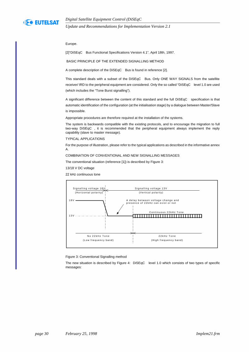
The conventional situation (reference [1]) is described by Figure 3:
13/18 V DC voltage
22 kHz continuous tone
Figure 3: Conventional Signalling method
The new situation is described by Figure 4: DiSEqC level 1.0 which consists of two types of specificmessages:
S i g n a l l i n g v o l t a g e 1 8 V
( H o r i z o n t a l p o l a r i t y )
C o n t i n u o u s 2 2 k H z T o n e
S i g n a l l i n g v o l t a g e 1 3 V
(Ve r t i ca l po la r i t y )
1 8 V
1 3 V
N o 2 2 k H z T o n e
( L o w f r e q u e n c y b a n d )
2 2 k H z T o n e
( H i g h f r e q u e n c y b a n d )
A d e l a y b e t w e e n v o l t a g e c h a n g e a n dp r e s e n c e o f 2 2 k H z c a n e x i s t o r n o t
page 31 February 25, 1998 Implem21.frm
Update and Recommendations for Implementation Version 2.1
Digital Satellite Equipment Control (DiSEqC )
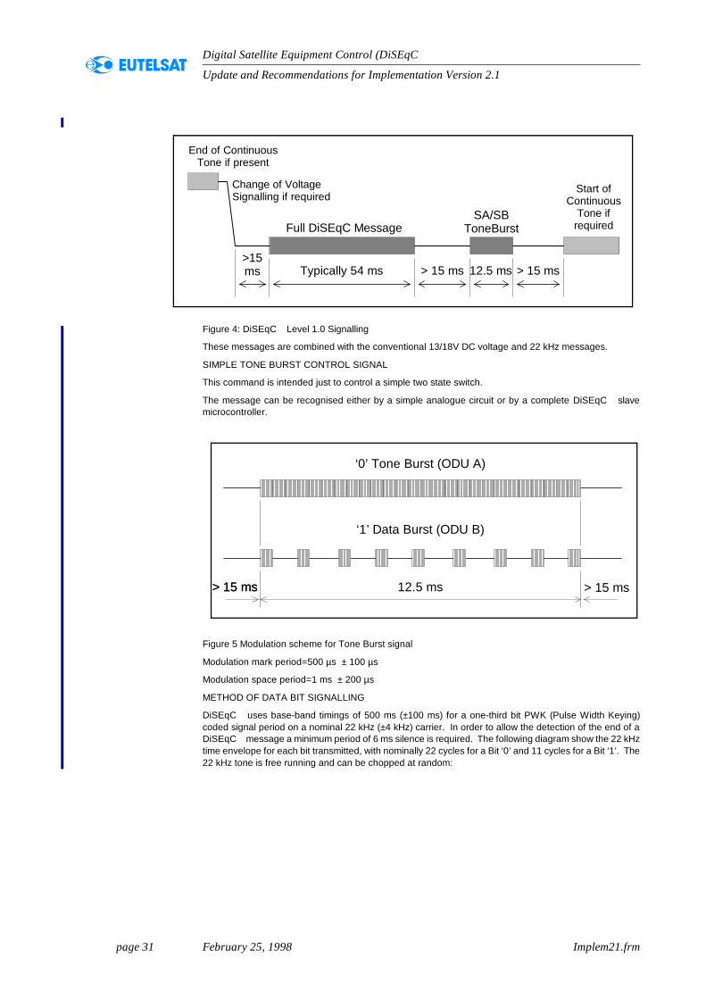
Figure 4: DiSEqC Level 1.0 Signalling
These messages are combined with the conventional 13/18V DC voltage and 22 kHz messages.
SIMPLE TONE BURST CONTROL SIGNAL
This command is intended just to control a simple two state switch.
The message can be recognised either by a simple analogue circuit or by a complete DiSEqC slavemicrocontroller.
Figure 5 Modulation scheme for Tone Burst signal
Modulation mark period=500 µs ± 100 µs
Modulation space period=1 ms ± 200 µs
METHOD OF DATA BIT SIGNALLING
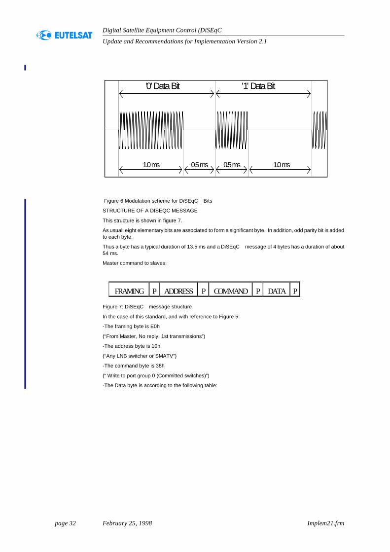
DiSEqC uses base-band timings of 500 ms (±100 ms) for a one-third bit PWK (Pulse Width Keying)coded signal period on a nominal 22 kHz (±4 kHz) carrier. In order to allow the detection of the end of aDiSEqC message a minimum period of 6 ms silence is required. The following diagram show the 22 kHztime envelope for each bit transmitted, with nominally 22 cycles for a Bit ‘0’ and 11 cycles for a Bit ‘1’. The22 kHz tone is free running and can be chopped at random:
End of ContinuousTone if present
Full DiSEqC MessageSA/SB
ToneBurst
Start ofContinuous
Tone ifrequired
Typically 54 ms>15ms > 15 ms> 15 ms 12.5 ms
Change of VoltageSignalling if required
‘0’ Tone Burst (ODU A)
‘1’ Data Burst (ODU B)
12.5 ms> 15 ms> 15 ms > 15 ms
page 32 February 25, 1998 Implem21.frm
Update and Recommendations for Implementation Version 2.1
Digital Satellite Equipment Control (DiSEqC )
Figure 6 Modulation scheme for DiSEqC Bits
STRUCTURE OF A DISEQC MESSAGE
This structure is shown in figure 7.
As usual, eight elementary bits are associated to form a significant byte. In addition, odd parity bit is addedto each byte.
Thus a byte has a typical duration of 13.5 ms and a DiSEqC message of 4 bytes has a duration of about54 ms.
Master command to slaves:
Figure 7: DiSEqC message structure
In the case of this standard, and with reference to Figure 5:
-The framing byte is E0h
(“From Master, No reply, 1st transmissions”)
-The address byte is 10h
(“Any LNB switcher or SMATV”)
-The command byte is 38h
(“Write to port group 0 (Committed switches)”)
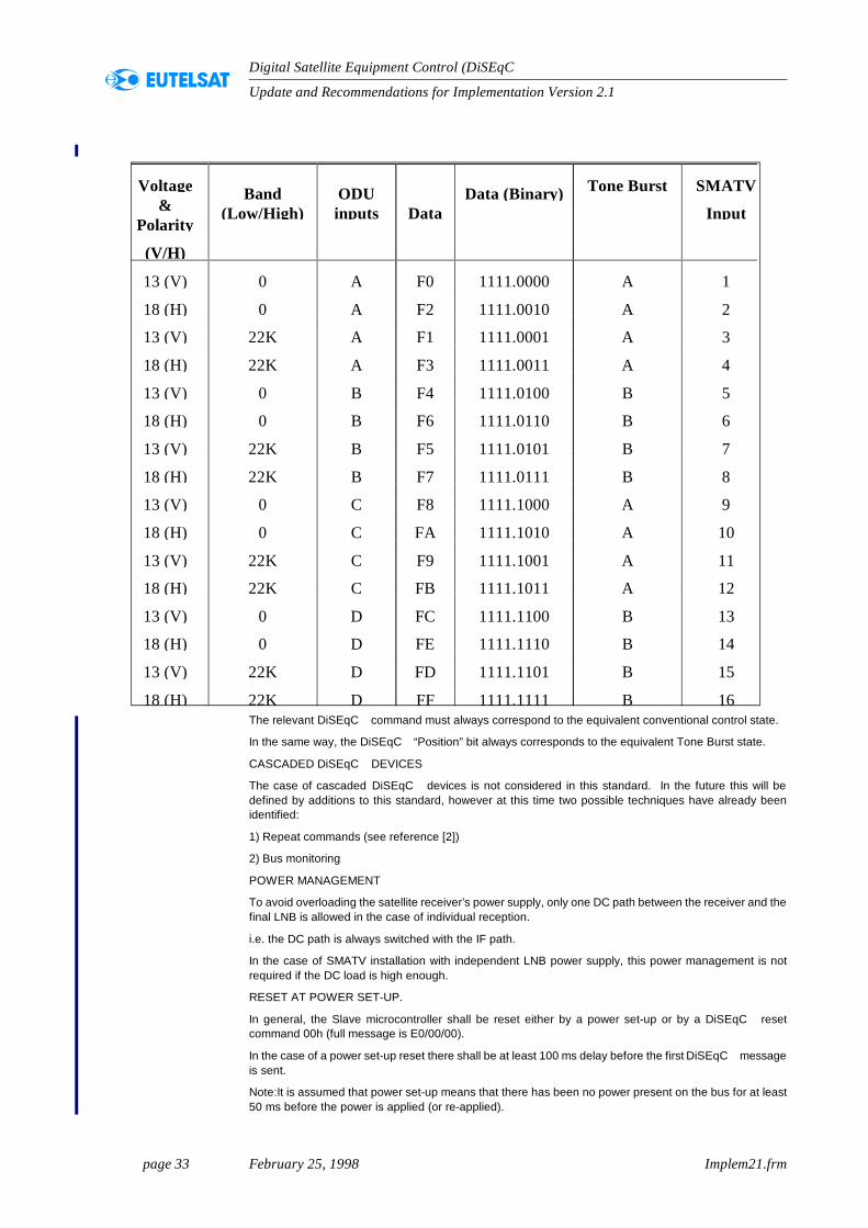
-The Data byte is according to the following table:
1.0 ms 0.5 ms
'0' Data Bit
1.0 ms0.5 ms
'1' Data Bit
FRAMING P ADDRESS P COMMAND P DATA P
page 33 February 25, 1998 Implem21.frm
Update and Recommendations for Implementation Version 2.1
Digital Satellite Equipment Control (DiSEqC )
The relevant DiSEqC command must always correspond to the equivalent conventional control state.
In the same way, the DiSEqC “Position” bit always corresponds to the equivalent Tone Burst state.
CASCADED DiSEqC DEVICES
The case of cascaded DiSEqC devices is not considered in this standard. In the future this will bedefined by additions to this standard, however at this time two possible techniques have already beenidentified:
1) Repeat commands (see reference [2])
2) Bus monitoring
POWER MANAGEMENT
To avoid overloading the satellite receiver’s power supply, only one DC path between the receiver and thefinal LNB is allowed in the case of individual reception.
i.e. the DC path is always switched with the IF path.
In the case of SMATV installation with independent LNB power supply, this power management is notrequired if the DC load is high enough.
RESET AT POWER SET-UP.
In general, the Slave microcontroller shall be reset either by a power set-up or by a DiSEqC resetcommand 00h (full message is E0/00/00).
In the case of a power set-up reset there shall be at least 100 ms delay before the first DiSEqC messageis sent.
Note:It is assumed that power set-up means that there has been no power present on the bus for at least50 ms before the power is applied (or re-applied).
Voltage&
Polarity
(V/H)
Band(Low/High)
ODUinputs Data
Data (Binary) Tone Burst SMATV
Input
13 (V) 0 A F0 1111.0000 A 1
18 (H) 0 A F2 1111.0010 A 2
13 (V) 22K A F1 1111.0001 A 3
18 (H) 22K A F3 1111.0011 A 4
13 (V) 0 B F4 1111.0100 B 5
18 (H) 0 B F6 1111.0110 B 6
13 (V) 22K B F5 1111.0101 B 7
18 (H) 22K B F7 1111.0111 B 8
13 (V) 0 C F8 1111.1000 A 9
18 (H) 0 C FA 1111.1010 A 10
13 (V) 22K C F9 1111.1001 A 11
18 (H) 22K C FB 1111.1011 A 12
13 (V) 0 D FC 1111.1100 B 13
18 (H) 0 D FE 1111.1110 B 14
13 (V) 22K D FD 1111.1101 B 15
18 (H) 22K D FF 1111.1111 B 16
page 34 February 25, 1998 Implem21.frm
Update and Recommendations for Implementation Version 2.1
Digital Satellite Equipment Control (DiSEqC )
RESET WHEN USING LOOP THROUGH TUNERS
For receivers employing an IF Loop-Through (e.g. digital IRDs with a loop-through for an analoguereceiver) must include a reset for the Slave IC each time the IF path is switched, to ensure backwardscompatibility with non-DiSEqC receivers. Please refer to the following figures:
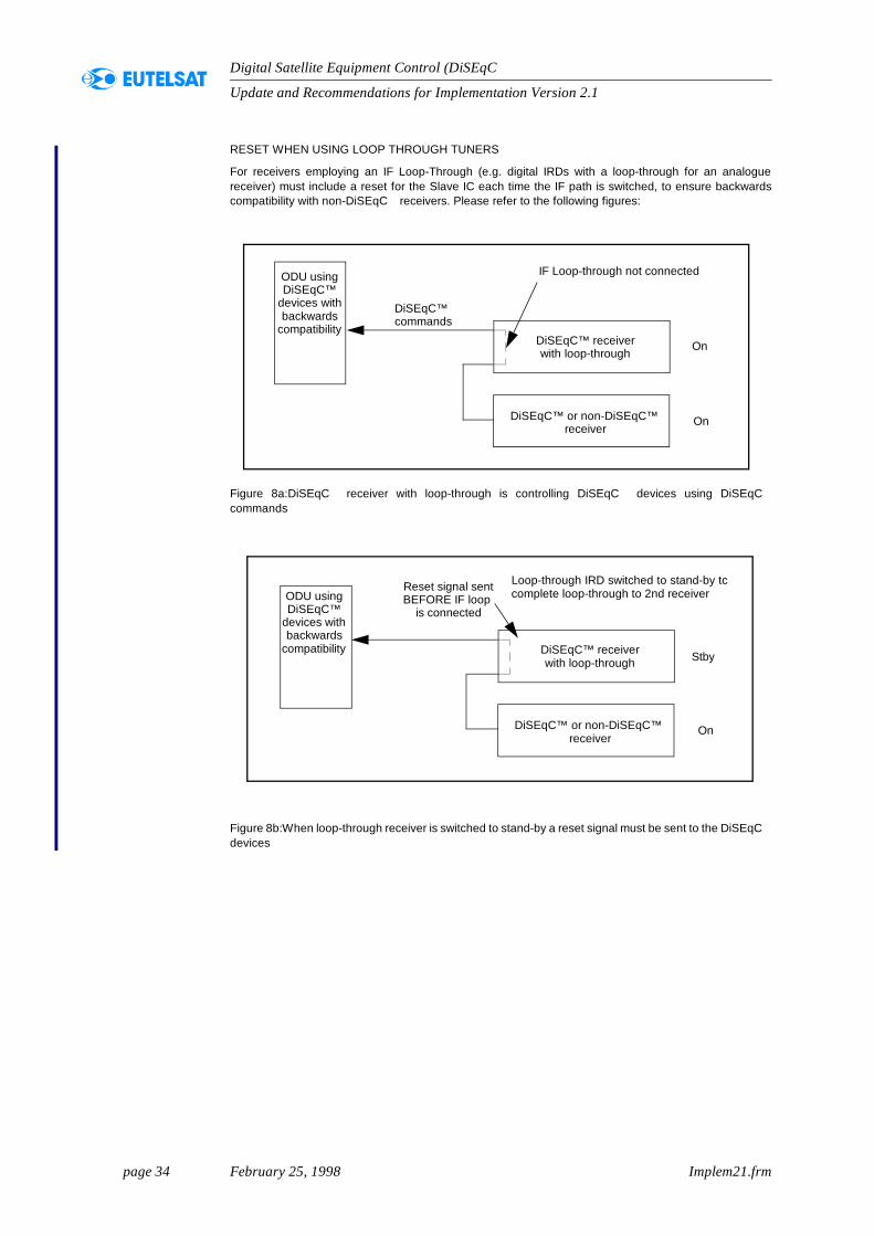
Figure 8a:DiSEqC receiver with loop-through is controlling DiSEqC devices using DiSEqCcommands
Figure 8b:When loop-through receiver is switched to stand-by a reset signal must be sent to the DiSEqCdevices
On
IF Loop-through not connectedODU usingDiSEqC™
devices withbackwards
compatibilityDiSEqC™ receiverwith loop-through
DiSEqC™ or non-DiSEqC™ receiver
On
DiSEqC™ commands
Stby
On
Loop-through IRD switched to stand-by tccomplete loop-through to 2nd receiverODU using
DiSEqC™devices withbackwards
compatibility DiSEqC™ receiverwith loop-through
DiSEqC™ or non-DiSEqC™ receiver
Reset signal sentBEFORE IF loop
is connected
page 35 February 25, 1998 Implem21.frm
Update and Recommendations for Implementation Version 2.1
Digital Satellite Equipment Control (DiSEqC )
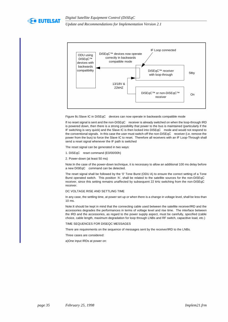
Figure 8c:Slave IC in DiSEqC devices can now operate in backwards compatible mode
If no reset signal is sent and the non-DiSEqC receiver is already switched on when the loop-through IRDis powered down, then there is a strong possibility that power to the bus is maintained (particularly if theIF switching is very quick) and the Slave IC is then locked into DiSEqC mode and would not respond tothe conventional signals. In this case the user must switch-off the non-DiSEqC receiver (i.e. remove thepower from the bus) to force the Slave IC to reset. Therefore all receivers with an IF Loop-Through shallsend a reset signal whenever the IF path is switched
The reset signal can be generated in two ways:
1. DiSEqC reset command (E0/00/00h)
2. Power-down (at least 50 ms)
Note:In the case of the power-down technique, it is necessary to allow an additional 100 ms delay beforea new DiSEqC command can be detected.
The reset signal shall be followed by the ‘0’ Tone Burst (ODU A) to ensure the correct setting of a ToneBurst operated switch. This position ‘A’, shall be related to the satellite sources for the non-DiSEqCreceiver, since this setting remains unaffected by subsequent 22 kHz switching from the non-DiSEqCreceiver.
DC VOLTAGE RISE AND SETTLING TIME
In any case, the settling time, at power set up or when there is a change in voltage level, shall be less than10 ms.
Note:It should be kept in mind that the connecting cable used between the satellite receiver/IRD and theaccessories degrades the performances in terms of voltage level and rise time. The interface betweenthe IRD and the accessories, as regard to the power supply aspect, must be carefully, specified (cablechoice, cable length, maximum degradation for loop through LNBs and RF switch, capacitive load, etc.)
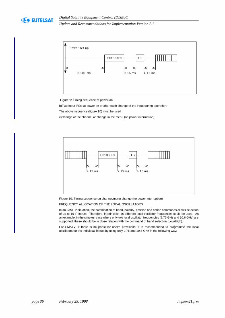
TIME SEQUENCES FOR DISEQC MESSAGES
There are requirements on the sequence of messages sent by the receiver/IRD to the LNBs.
Three cases are considered:
a)One input IRDs at power on:
Stby
On
IF Loop connected
ODU usingDiSEqC™
devices withbackwards
compatibility DiSEqC™ receiverwith loop-through
DiSEqC™ or non-DiSEqC™ receiver
DiSEqC™ devices now operatecorrectly in backwards
compatible mode
13/18V &22kHZ
page 36 February 25, 1998 Implem21.frm
Update and Recommendations for Implementation Version 2.1
Digital Satellite Equipment Control (DiSEqC )
Figure 9: Timing sequence at power-on
b)Two input IRDs at power on or after each change of the input during operation:
The above sequence (figure 10) must be used
c)Change of the channel or change in the menu (no power interruption)
Figure 10: Timing sequence on channel/menu change (no power interruption)
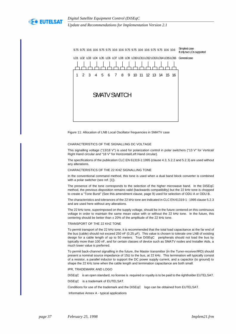
FREQUENCY ALLOCATION OF THE LOCAL OSCILLATORS
In an SMATV situation, the combination of band, polarity, position and option commands allows selectionof up to 16 IF inputs. Therefore, in principle, 16 different local oscillator frequencies could be used. Asan example, in the simplest case where only two local oscillator frequencies (9.75 GHz and 10.6 GHz) aresupported, these should be in close relation with the command of band selection (Low/High).
For SMATV, if there is no particular user’s provisions, it is recommended to programme the localoscillators for the individual inputs by using only 9.75 and 10.6 GHz in the following way:
E01038Fx TB
Power set-up
> 100 ms > 15 ms > 15 ms
E01038Fx TB
> 15 ms > 15 ms> 15 ms
page 37 February 25, 1998 Implem21.frm
Update and Recommendations for Implementation Version 2.1
Digital Satellite Equipment Control (DiSEqC )
Figure 11: Allocation of LNB Local Oscillator frequencies in SMATV case
CHARACTERISTICS OF THE SIGNALLING DC VOLTAGE
This signalling voltage (“13/18 V”) is used for polarization control in polar switchers (“13 V” for Vertical/Right Hand circular and “18 V” for Horizontal/Left Hand circular).
The specifications of the publication CLC EN 61319-1:1995 (clause 4.3, 5.2.2 and 5.2.3) are used withoutany alterations.
CHARACTERISTICS OF THE 22 KHZ SIGNALLING TONE
In the conventional command method, this tone is used when a dual band block converter is combinedwith a polar switcher (see ref. [1]).
The presence of the tone corresponds to the selection of the higher microwave band. In the DiSEqCmethod, the previous disposition remains valid (backwards compatibility) but the 22 kHz tone is choppedto create a “Tone Burst” (See this amendment clause, page 9) used for selection of ODU A or ODU B.
The characteristics and tolerances of the 22 kHz tone are indicated in CLC EN 61319-1 : 1995 clause 5.2.3and are used here without any alterations.
The 22 kHz tone, superimposed on the supply voltage, should be in the future centered on this continuousvoltage in order to maintain the same mean value with or without the 22 kHz tone. In the future, thiscentering should be better than ± 20% of the amplitude of the 22 kHz tone.
TRANSPORT OF THE 22 KHZ TONE
To permit transport of the 22 kHz tone, it is recommended that the total load capacitance at the far end ofthe bus (cable) should not exceed 250 nF (0.25 µF). This value is chosen to tolerate one LNB of existingdesign for a cable length of up to 50 meters. True DiSEqC peripherals should not load the bus bytypically more than 100 nF, and for certain classes of device such as SMATV nodes and Installer Aids, amuch lower value is preferred.
To permit back-channel signalling in the future, the Master transmitter (in the Tuner-receiver/IRD) shouldpresent a nominal source impedance of 15Ω to the bus, at 22 kHz. This termination will typically consistof a resistor, a parallel inductor to support the DC power supply current, and a capacitor (to ground) toshape the 22 kHz tone when the cable length and termination capacitance are both small.
IPR, TRADEMARK AND LOGO
DiSEqC is an open standard, no license is required or royalty is to be paid to the rightholder EUTELSAT.
DiSEqC is a trademark of EUTELSAT.
Conditions for use of the trademark and the DiSEqC logo can be obtained from EUTELSAT.
Informative Annex A - typical applications
LO1
9.75
LO2 LO3 LO4 LO5 LO6 LO7 LO8 LO9 LO10LO11LO12LO13LO14LO15LO16
9.75 10.6 10.6 9.75 9.75 10.6 10.6 9.75 9.75 10.6 10.6 9.75 9.75 10.6 10.6
SMATV SWITCH
Simplest caseIf only two LOs supported
1 2 3 4 5 6 7 8 9 10 11 12 13 14 15 16
General case
page 38 February 25, 1998 Implem21.frm
Update and Recommendations for Implementation Version 2.1
Digital Satellite Equipment Control (DiSEqC )
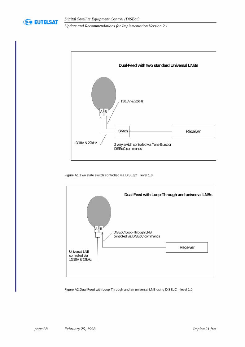
Figure A1:Two state switch controlled via DiSEqC level 1.0
Figure A2:Dual Feed with Loop Through and an universal LNB using DiSEqC level 1.0
Dual-Feed with two standard Universal LNBs
ReceiverSwitch
13/18V & 22kHz
13/18V & 22kHz 2 way switch controlled via Tone Burst orDiSEqC commands
A B
Dual-Feed with Loop-Through and universal LNBs
Receiver
DiSEqC Loop-Through LNBcontrolled via DiSEqC commands
Universal LNBcontrolled via13/18V & 22kHz
A B
page 39 February 25, 1998 Implem21.frm
Update and Recommendations for Implementation Version 2.1
Digital Satellite Equipment Control (DiSEqC )
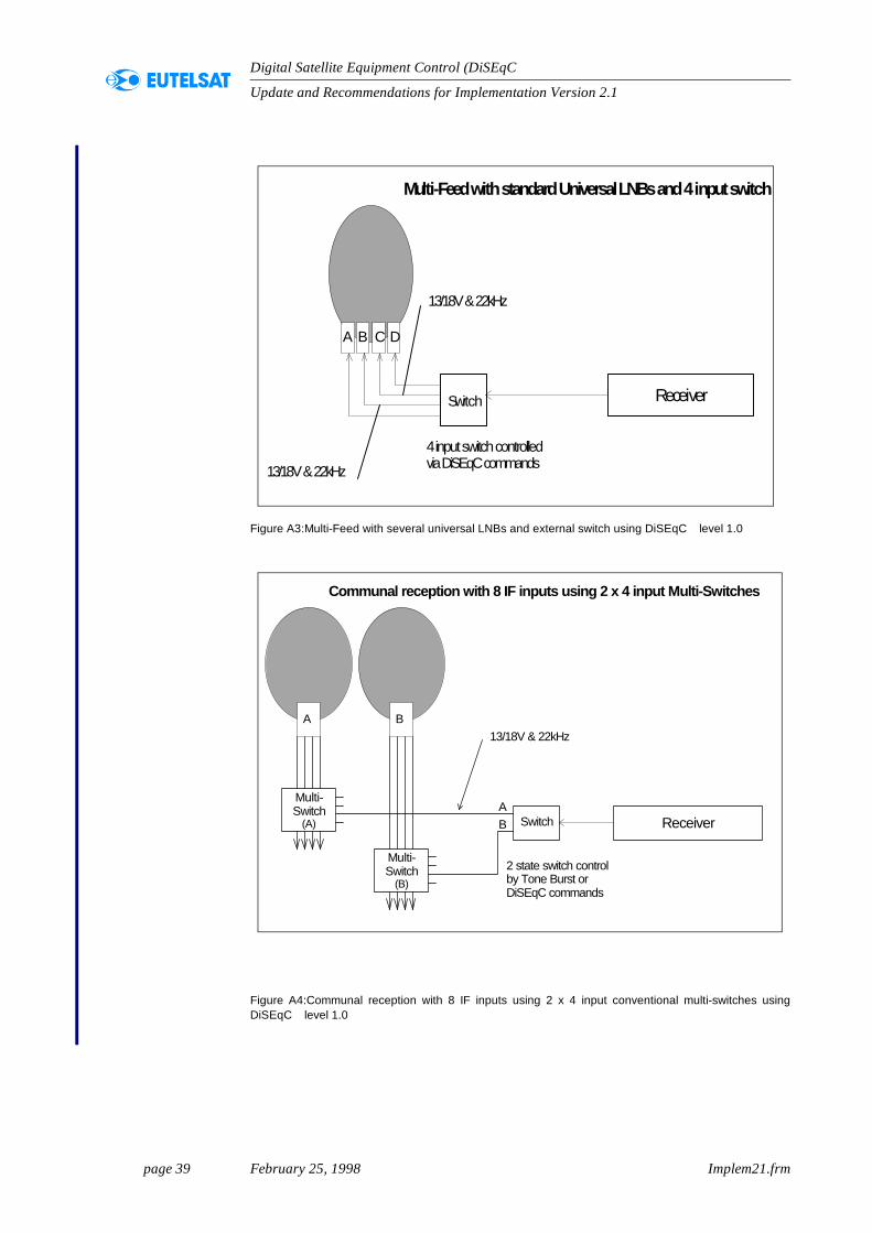
Figure A3:Multi-Feed with several universal LNBs and external switch using DiSEqC level 1.0
Figure A4:Communal reception with 8 IF inputs using 2 x 4 input conventional multi-switches usingDiSEqC level 1.0
Multi-Feed with standard Universal LNBs and 4 input switch
ReceiverSwitch
13/18V & 22kHz
13/18V & 22kHz
4 input switch controlledvia DiSEqC commands
A B C D
Communal reception with 8 IF inputs using 2 x 4 input Multi-Switches
Receiver
Multi-Switch
(B)
13/18V & 22kHz
Multi-Switch
(A) Switch
2 state switch controlby Tone Burst orDiSEqC commands
A B
AB
page 40 February 25, 1998 Implem21.frm
Update and Recommendations for Implementation Version 2.1
Digital Satellite Equipment Control (DiSEqC )
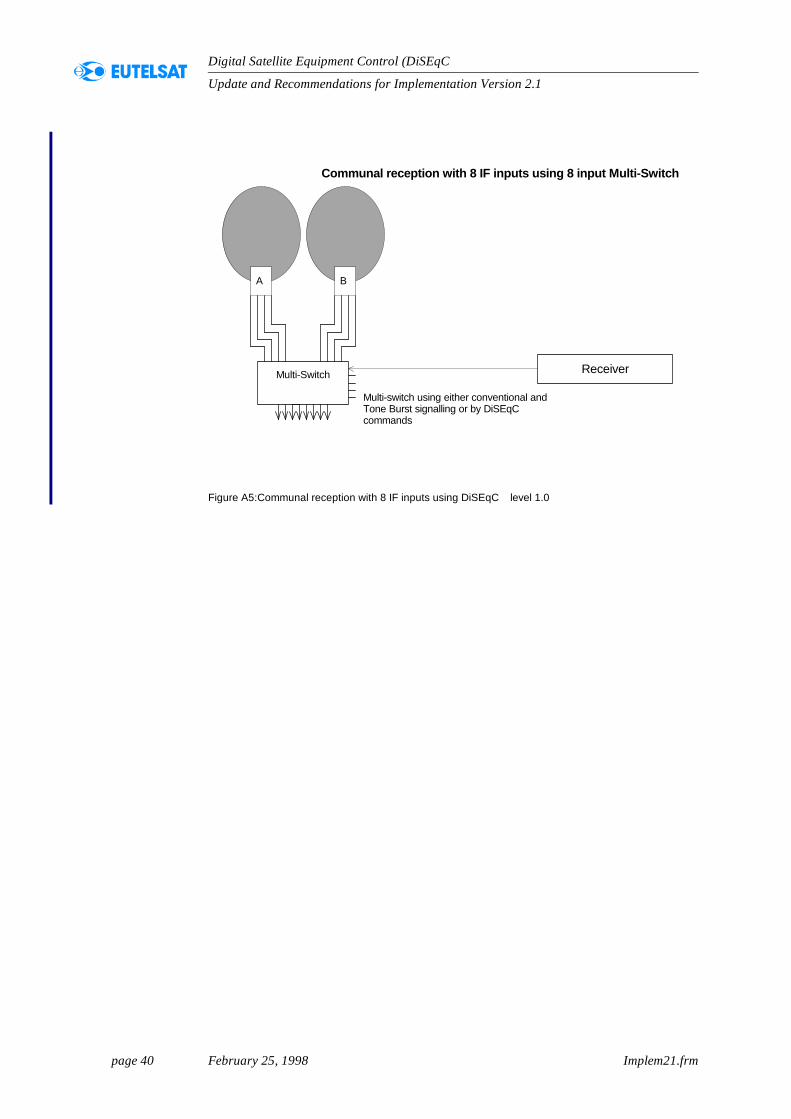
Figure A5:Communal reception with 8 IF inputs using DiSEqC level 1.0
Communal reception with 8 IF inputs using 8 input Multi-Switch
ReceiverMulti-Switch
Multi-switch using either conventional andTone Burst signalling or by DiSEqCcommands
A B