Embed Size (px)
DESCRIPTION
rect wave guide perturbation
Citation preview
PERTURBATION IN RECTANGULAR WAVEGUIDE RESONATOR
Submitted by: Makwana Milan K. 13104073Ratnesh Tiwari 13104119
Under Guidance of :Prof. J. Akhtar
EE 641 Advanced Engineering Electromagnetics
Under Guidance of :Prof. J. AkhtarDept. of Electrical EngineeringIndian Institute of Technology Kanpur
OUTLINES:
1ntroduction
Rectangular Waveguide Resonator
Perturbation In Waveguide Resonator
SimulationSimulation
References
EE 641 Advanced Engineering Electromagnetics
1. Introduction
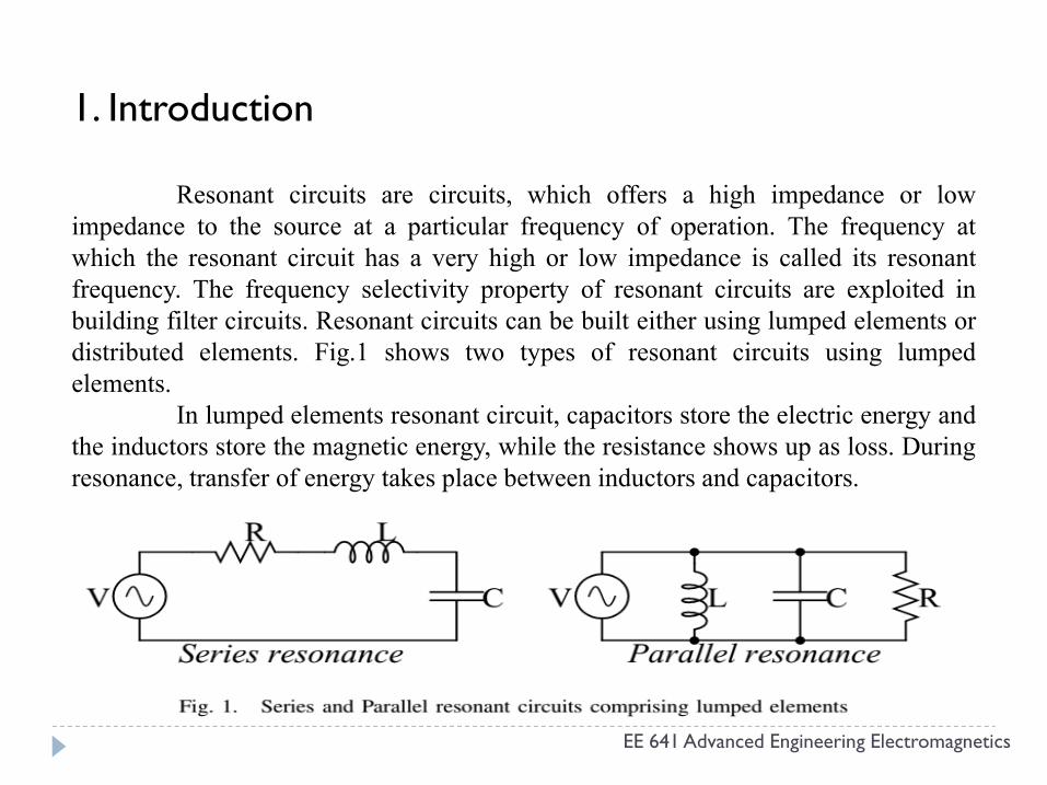
Resonant circuits are circuits, which offers a high impedance or lowimpedance to the source at a particular frequency of operation. The frequency atwhich the resonant circuit has a very high or low impedance is called its resonantfrequency. The frequency selectivity property of resonant circuits are exploited inbuilding filter circuits. Resonant circuits can be built either using lumped elements ordistributed elements. Fig.1 shows two types of resonant circuits using lumpedelements.
EE 641 Advanced Engineering Electromagnetics
elements.In lumped elements resonant circuit, capacitors store the electric energy and
the inductors store the magnetic energy, while the resistance shows up as loss. Duringresonance, transfer of energy takes place between inductors and capacitors.
Another type of resonant circuits is the distributed resonant circuit, which utilizesan open or shorted transmission line. The resonance occurs in the form of standingwaves due to superposition of the forward and reverse traveling waves. We will seethat any form of transmission line of suitable lenghts can be used as a resonator.
When the transmission line used is a waveguide, the resulting resonator is calleda cavity resonator and the resonator is called a strip resonator when a microstrip isused as the transmission line.
Lumped element resonators have several limitations over waveguide resonatorsas following.
EE 641 Advanced Engineering Electromagnetics
as following.
• Lumped element resonant circuits are usually limited to 10GHz as the capacitanceand inductance values required to get very high resonant frequency becomes too smallto be fabricated. This rules out the use of them at frequencies above 7-10 GHz E.g., X-band (8-12 GHz) and K-band (18-27 GHz) radar systems.
• Simplicity in construction of waveguide resonators is an added advantage.
2.Rectangular Waveguide Resonator
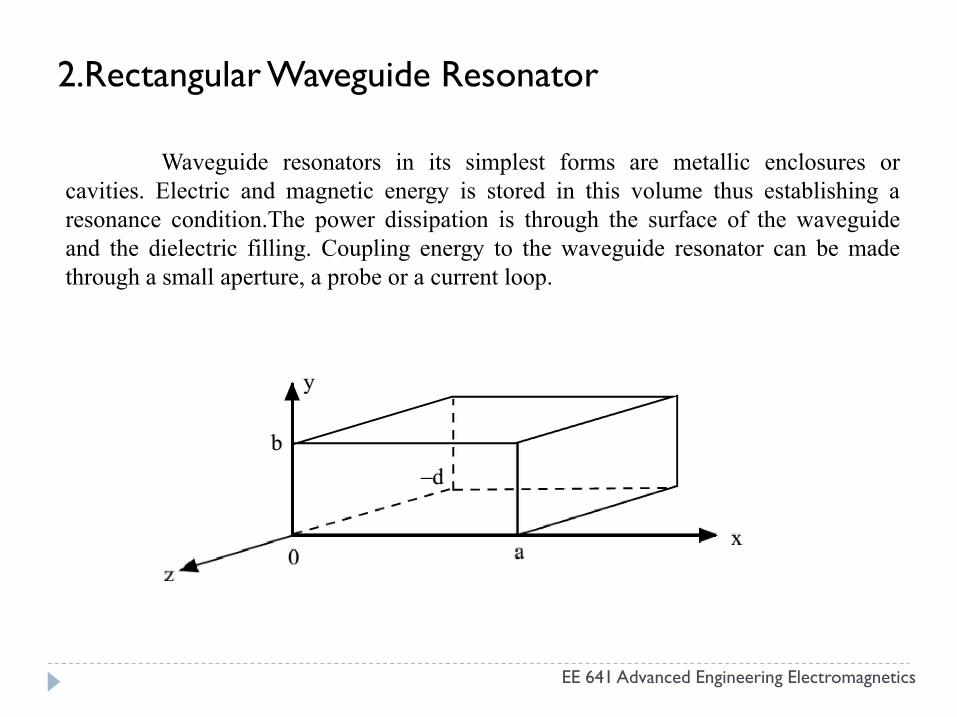
Waveguide resonators in its simplest forms are metallic enclosures orcavities. Electric and magnetic energy is stored in this volume thus establishing aresonance condition.The power dissipation is through the surface of the waveguideand the dielectric filling. Coupling energy to the waveguide resonator can be madethrough a small aperture, a probe or a current loop.
EE 641 Advanced Engineering Electromagnetics
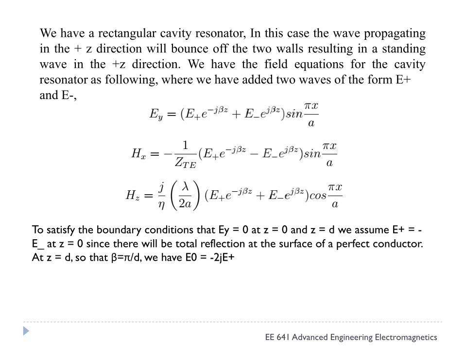
We have a rectangular cavity resonator, In this case the wave propagatingin the + z direction will bounce off the two walls resulting in a standingwave in the +z direction. We have the field equations for the cavityresonator as following, where we have added two waves of the form E+and E-,
EE 641 Advanced Engineering Electromagnetics
To satisfy the boundary conditions that Ey = 0 at z = 0 and z = d we assume E+ = -E_ at z = 0 since there will be total reflection at the surface of a perfect conductor. At z = d, so that β=π/d, we have E0 = -2jE+
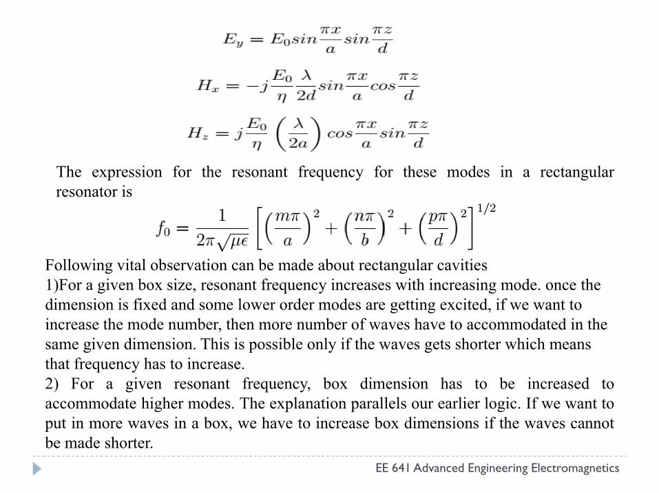
The expression for the resonant frequency for these modes in a rectangularresonator is
EE 641 Advanced Engineering Electromagnetics
Following vital observation can be made about rectangular cavities 1)For a given box size, resonant frequency increases with increasing mode. once the dimension is fixed and some lower order modes are getting excited, if we want to increase the mode number, then more number of waves have to accommodated in the same given dimension. This is possible only if the waves gets shorter which means that frequency has to increase.2) For a given resonant frequency, box dimension has to be increased toaccommodate higher modes. The explanation parallels our earlier logic. If we want toput in more waves in a box, we have to increase box dimensions if the waves cannotbe made shorter.
3. Perturbation in Rectangular cavity
We have a technique to evaluate the dielectric constant of a homogeneousdielectric material using rectangular shaped perturb cavity. The values of S-parametersare measured experimentally by placing the sample in the center of the cavityresonator. Sample under test is fabricated in the form of a cylinder. The real part of thepermittivity which is dielectric constant can be then calculated from the shift in theresonance frequency. We have also shown the electric and magnetic fields insideresonator with perturbation and without perturbation.
It involve approximations in their formulation which lead to acceptableresults only under very restricted conditions:
EE 641 Advanced Engineering Electromagnetics
results only under very restricted conditions:(i) The sample must be very small compared with the cavity itself so that a frequency
shift which is small compared with the resonant frequency shift of the emptycavity is produced by the insertion of the sample.
(ii) The cavity without and with sample must be very much alike.The cavity perturbation method has been extensively used for measuring
dielectric parameters of material at microwave frequencies. a cavity has been designedwith very small slot at the center of broader side of the waveguide in order to insert asample material.
Using cavity perturbation technique rectangular cavity resonator is designed tomeasure the dielectric parameters of Teflon. Measuring resonance frequency of emptycavity and then measuring the shift in resonance frequency with the sample materialplaced at its center and then the dielectric constant is calculated from the shift inresonance frequency. The material under test (Teflon) is fabricated in the form of acylinder and inserted into the center of the rectangular cavity. This measurement methodalso describes the application of perturbation method to a microwave cavity resonatorwith a dielectric perturbed.
THEORETICAL ANALYSIS :-
For the material filling a part of the cavity resonator, the permittivity is expressed
EE 641 Advanced Engineering Electromagnetics
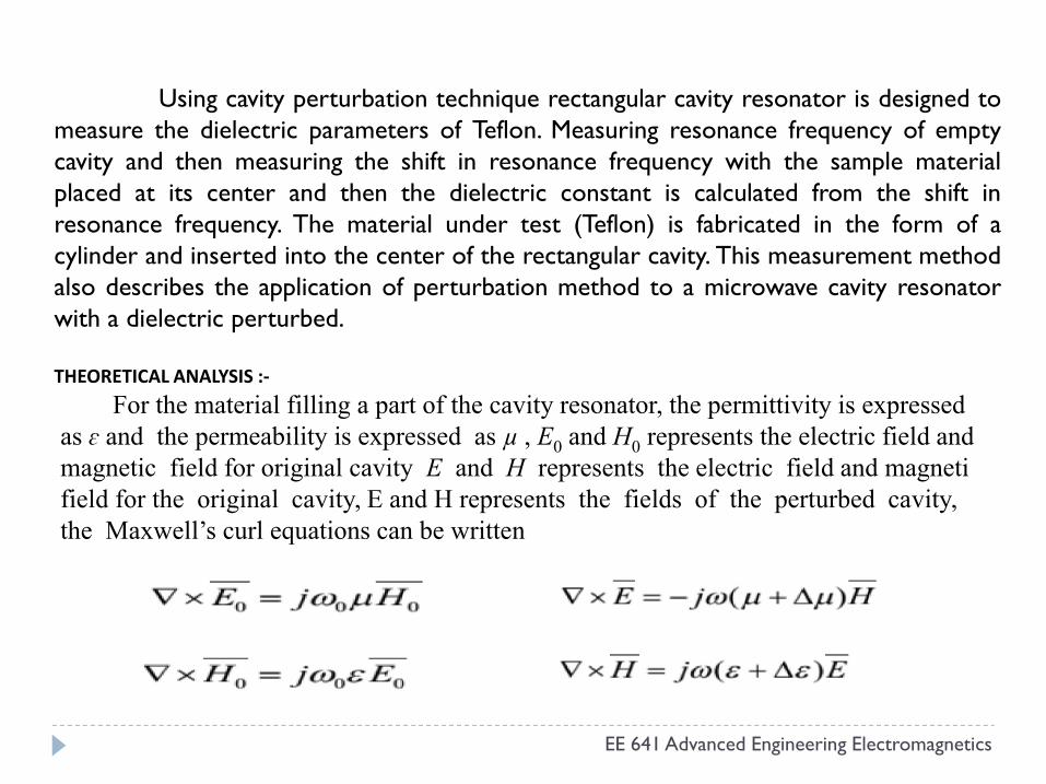
For the material filling a part of the cavity resonator, the permittivity is expressed as ɛ and the permeability is expressed as µ , E0 and H0 represents the electric field andmagnetic field for original cavity E and H represents the electric field and magnetifield for the original cavity, E and H represents the fields of the perturbed cavity, the Maxwell’s curl equations can be written
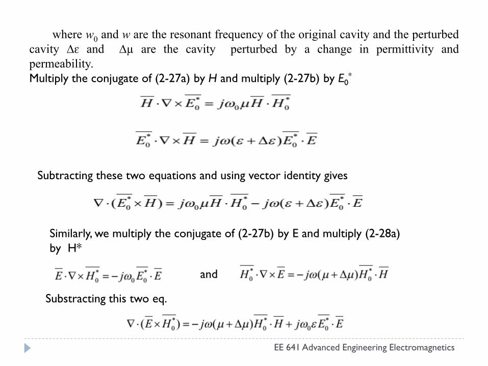
where w0 and w are the resonant frequency of the original cavity and the perturbedcavity ∆ɛ and ∆µ are the cavity perturbed by a change in permittivity andpermeability.Multiply the conjugate of (2-27a) by H and multiply (2-27b) by E0
*
Subtracting these two equations and using vector identity gives
EE 641 Advanced Engineering Electromagnetics
Similarly, we multiply the conjugate of (2-27b) by E and multiply (2-28a) by H*
and
Substracting this two eq.
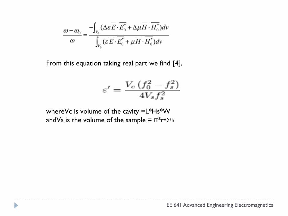
From this equation taking real part we find [4],
whereVc is volume of the cavity =L*Hs*W
EE 641 Advanced Engineering Electromagnetics
whereVc is volume of the cavity =L*Hs*WandVs is the volume of the sample = π*r^2*h
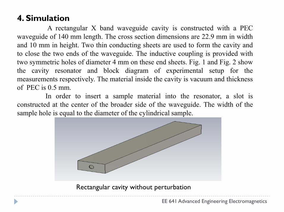
4. Simulation A rectangular X band waveguide cavity is constructed with a PEC
waveguide of 140 mm length. The cross section dimensions are 22.9 mm in widthand 10 mm in height. Two thin conducting sheets are used to form the cavity andto close the two ends of the waveguide. The inductive coupling is provided withtwo symmetric holes of diameter 4 mm on these end sheets. Fig. 1 and Fig. 2 showthe cavity resonator and block diagram of experimental setup for themeasurements respectively. The material inside the cavity is vacuum and thicknessof PEC is 0.5 mm.
In order to insert a sample material into the resonator, a slot isconstructed at the center of the broader side of the waveguide. The width of the
EE 641 Advanced Engineering Electromagnetics
constructed at the center of the broader side of the waveguide. The width of thesample hole is equal to the diameter of the cylindrical sample.
Rectangular cavity without perturbation
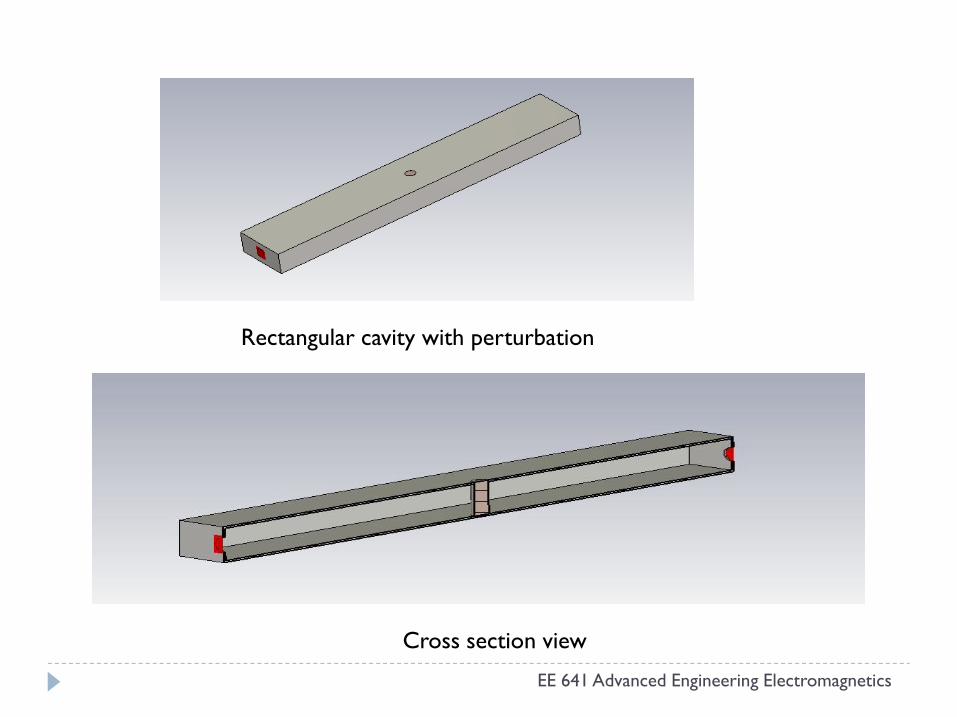
Rectangular cavity with perturbation
EE 641 Advanced Engineering Electromagnetics
Cross section view
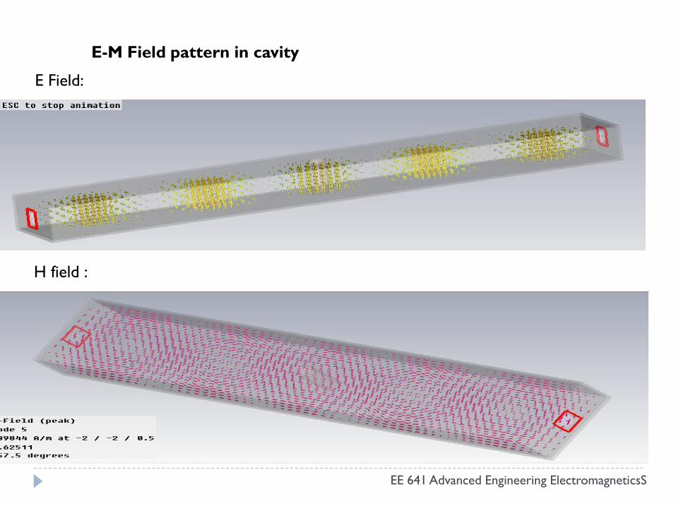
E-M Field pattern in cavity
E Field:
EE 641 Advanced Engineering ElectromagneticsS
H field :
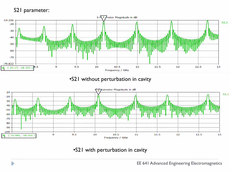
S21 parameter:
•S21 without perturbation in cavity
EE 641 Advanced Engineering Electromagnetics
•S21 with perturbation in cavity
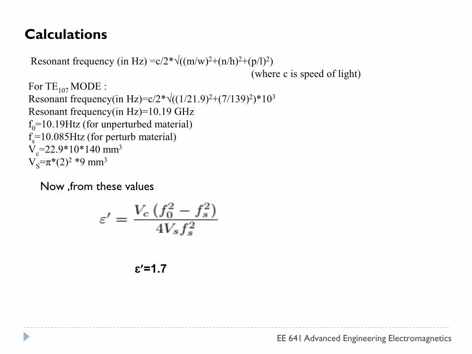
Calculations
Resonant frequency (in Hz) =c/2*√((m/w)2+(n/h)2+(p/l)2)(where c is speed of light)
For TE107 MODE :Resonant frequency(in Hz)=c/2*√((1/21.9)2+(7/139)2)*103
Resonant frequency(in Hz)=10.19 GHzf0=10.19Htz (for unperturbed material)fs=10.085Htz (for perturb material)Vc=22.9*10*140 mm3
VS=π*(2)2 *9 mm3
EE 641 Advanced Engineering Electromagnetics
Now ,from these values
ɛ’=1.7
5. References
1. Harrington, R. F., Time-Harmonic Electromagnetic Fields, McGraw-Hill, New York, 1961.
2. C.A.Balanis, Advanced Engineering electromagnetics, John Wiley & Sons, Inc3. A. Kumar and S. Sharma, Measurement of dielectri constant and loss factor of
dieelectric material, Progress In Electromagnetics Research, PIER 69, 47–54, 2007
4. 4. Meng, B., J. Booske, and R. Cooper, “Extended cavity perturbation technique to determine the complex permittivity of the dielectric materials,” IEEE Trans.
EE 641 Advanced Engineering Electromagnetics
to determine the complex permittivity of the dielectric materials,” IEEE Trans. Microwave Theory Tech., Vol. 43, 2633–2636, 1995.
5. 5. Vaid, J. K., A. Prakash, and A. Mansingh, “Measurement of dielectric parameters at microwave frequencies by cavity perturbation technique,”IEEETrans. Microwave Theory Tech., Vol. 27, 791–795, Sep. 1979.
6. 6. Waldron, R. A., “Perturbation theory of resonant cavities,”Proc. IEE, Vol. 170C, 272–274, 1960.
EE 641 Advanced Engineering Electromagnetics