Embed Size (px)
Citation preview
Unmanned Aerial Systems for Forest Operations - Technology Watch Technical report no. 44 - October 2015
By: Karine Jean and Patrick Ménard, Centre Géomatique du Québec Udaya Vepakomma and Denis Cormier, FPInnovations
fpinnovations.ca

FPInnovations is a not-for-profit world-leading
R&D institute that specializes in the creation of
scientific solutions in support of the Canadian
forest sector’s global competitiveness and
responds to the priority needs of its industry
members and government partners. It is ideally
positioned to perform research, innovate, and
deliver state-of-the-art solutions for every area
of the sector’s value chain, from forest
operations to consumer and industrial
products. FPInnovations’ staff numbers more
than 525. Its R&D laboratories are located in
Québec City, Montréal and Vancouver, and it
has technology transfer offices across Canada.
For more information
about FPInnovations, visit:
www.fpinnovations.ca.
Follow us on:
CGQ is a college centre for technology transfer
(CCTT) affiliated with Cégep de Chicoutimi
and specialized in various fields of geomatics.
Among other things, it has developed a
recognized expertise in the areas of
unmanned aircraft, specialized cameras and processing of images acquired using UAS.
301009278: 4FS-SO-FO-TT3-Photogrammetry
Technical report no. 44
ABSTRACT Recent technological advances in the area of Unmanned Aerial Systems (UAS) have led to affordable and flexible solutions for planning forest operations and monitoring compliance. The report reviews the technology in a forestry context. It presents an overview of UAS and its components, provides information on current regulations and identifies key features for forestry applications.
ACKNOWLEDGEMENTS The contribution of the Centre de Géomatique du Québec to this project was funded in part by the Natural Sciences and Engineering Research Council (NSERC) through its College and Community Innovation Program – Applied Research and Development (ARD) grant, Level 1 and the industrial funding of FPInnovations. The participation of FPInnovations was also funded in part by Natural Resources Canada under the Transformative Technologies Program.
CONTACT Udaya Vepakomma Scientist Remote Sensing 514-782-4610 [email protected]
© 2014 FPInnovations. All rights reserved. Unauthorized copying or redistribution prohibited.
Disclosure for Commercial Application: If you require assistance to implement these research findings, please contact FPInnovations at [email protected].
FPInnovations Page 3
Table of Contents
1. BACKGROUND .............................................................................................................................. 4
Objectives .......................................................................................................................................... 5
2. OVERVIEW of TECHNOLOGY ....................................................................................................... 5
Definition and terminology .................................................................................................................. 5
Classification and type of vehicles ...................................................................................................... 7
Fixed-wing vehicles ........................................................................................................................ 7
VTOL vehicles ................................................................................................................................ 9
On-board sensors (payload) ............................................................................................................. 11
Visible sensors ............................................................................................................................. 12
Thermal infrared sensors .............................................................................................................. 12
Multispectral sensors .................................................................................................................... 12
Hyperspectral sensors .................................................................................................................. 13
LiDAR systems ............................................................................................................................. 13
Equipment for navigational control ................................................................................................... 14
UAS ground crew ............................................................................................................................. 14
3. LEGISLATION .............................................................................................................................. 14
Light UAS pilot training ..................................................................................................................... 15
Information required for an SFOC .................................................................................................... 15
Operations crew............................................................................................................................ 15
Description of operational plan ...................................................................................................... 15
Aircraft description ........................................................................................................................ 17
Emergency contingency plans ...................................................................................................... 17
4. TECHNOLOGY WATCH ............................................................................................................... 18
Platforms .......................................................................................................................................... 18
Sensors (cameras) ........................................................................................................................... 19
Image processing – 3D modeling software ....................................................................................... 19
5. SUGGESTED SYSTEM SETUP ................................................................................................... 20
Selecting a system ........................................................................................................................... 20
Training ............................................................................................................................................ 20
Data management ............................................................................................................................ 20
Quality of the outputs ....................................................................................................................... 21
6. CONCLUSION .............................................................................................................................. 21
FPInnovations Page 4
1. BACKGROUND
Forest sector stakeholders need up-to-date and comprehensive information on the state of the forests they manage. Conditions that affect planning are constantly changing, and often very quickly. These changes can have a significant impact on operational planning and treatment prescriptions. Remote sensing is known to be an effective mode of acquiring required information for evaluating managed forests compared to traditional ground surveys. However, information coming from conventional aircraft or satellites is often obsolete or too costly to collect when needed. Recent technological advances in the area of Unmanned Aerial Systems (UAS) have led to affordable and flexible solutions for planning forest operations and monitoring compliance. Nevertheless, since the market for civilian applications is now booming with several products at the prototype stage, it is necessary to take stock of progress made in the development of systems (vehicles, sensors and software) and identify those that are ready for deployment and suitable for forest operations
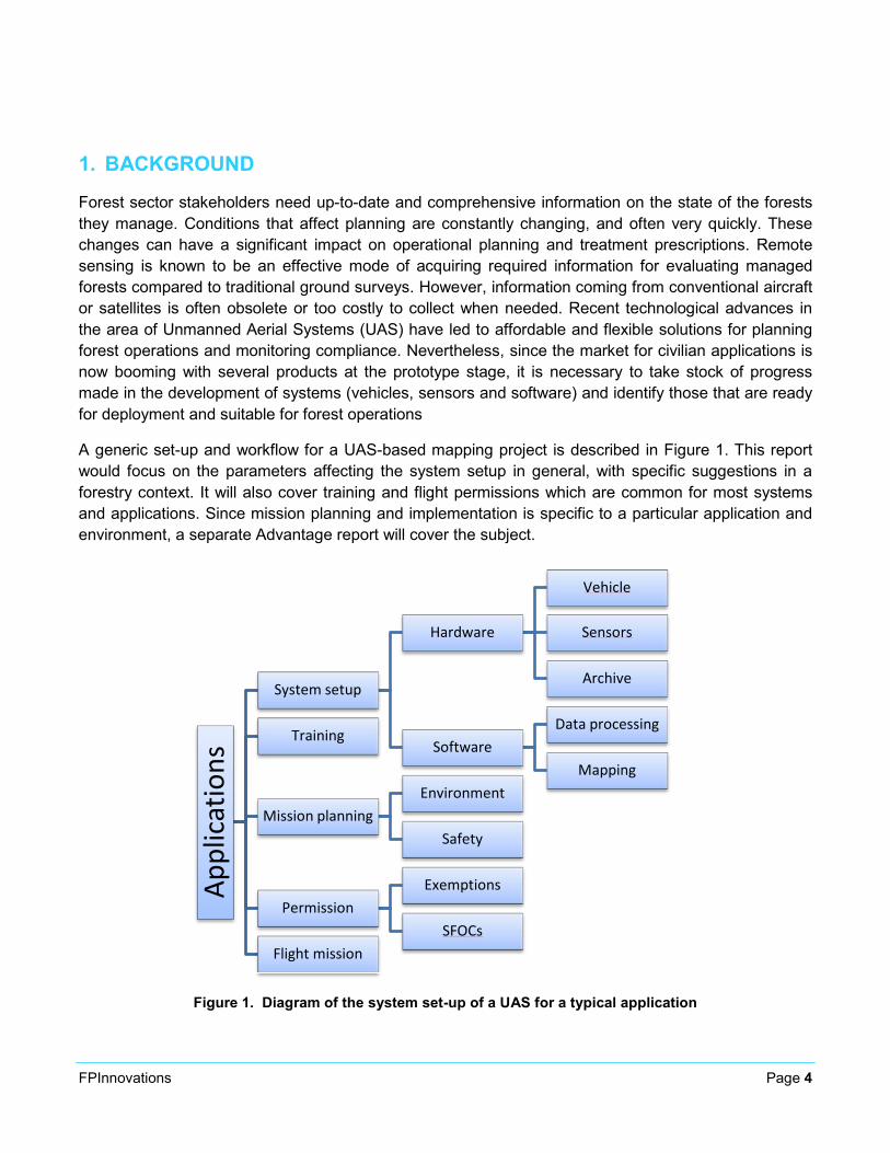
A generic set-up and workflow for a UAS-based mapping project is described in Figure 1. This report would focus on the parameters affecting the system setup in general, with specific suggestions in a forestry context. It will also cover training and flight permissions which are common for most systems and applications. Since mission planning and implementation is specific to a particular application and environment, a separate Advantage report will cover the subject.
Figure 1. Diagram of the system set-up of a UAS for a typical application
Appl
icat
ions
System setup
Hardware
Vehicle
Sensors
Archive
Software Data processing
Mapping
Training
Mission planning Environment
Safety
Permission Exemptions
SFOCs Flight mission
FPInnovations Page 5
Objectives The report reviews unmanned aircraft (UA) technology in a forestry context. More specifically, it aims to:
• Provide an overview of UA technology and its components, including: platform types and on-board sensors;
• Provide information on current regulations;
• Present a technology watch conducted on;
o Platforms, on-board sensors and imaging software currently available in the market;
• Identify key criteria for forestry applications.
2. OVERVIEW OF TECHNOLOGY
UAS have been part of the aeronautics landscape for over 20 years. Initially used by the military, their civilian applications in security, geology, archaeology, civil engineering, agriculture and forestry have been only recent. Unmanned aircraft technology can be in direct competition with airplanes and helicopters, especially for airborne image acquisition, but their deployment is noted to be more flexible (faster and more frequent) and less expensive to operate in small-scale projects. Although regulations governing UAS activity in Canada are still restrictive, the wide range of benefits provided by this technology point to a very promising future.
Definition and terminology As is often the case for new technologies, a consensus on the definition of a UAS and associated terminology is not yet reached. Around the world, several names are used to define UAS. For instance, the International Civil Aviation Organization uses the term “remotely-piloted aircraft system”. In Canada, section 101.01 of the Canadian Aviation Regulations (CARs) of Transport Canada defines UAS as follows:
An “unmanned air vehicle” means a power-driven aircraft, other than a model aircraft, that is designed to fly without a human operator on board.
Although the term unmanned air vehicle or UAV is used in CARs, no term is specifically used yet by Transport Canada. The name is therefore not regulated and several terms are seen in the industry:
• Drone
• Pilotless aircraft
• Remotely piloted aircraft
FPInnovations Page 6
• Remotely piloted aircraft system
• Remotely controlled systems
• Flying robots
The term “drone” is often avoided since some people wrongly associate it with military operations. In this report, the term “unmanned aerial system” and its acronym UAS will be used.
Remotely controlled aircraft are often confused with model aircraft used by aero-modelling enthusiasts. For Transport Canada, the difference between UAS and model aircraft is in the total weight of the aircraft. To be considered as a model aircraft, the aircraft must not exceed 35 kg (77.2 lb) and be used for recreational purposes. As soon as an aircraft is used for commercial or research purposes, it is considered a UAS and must be operated according to CARs.
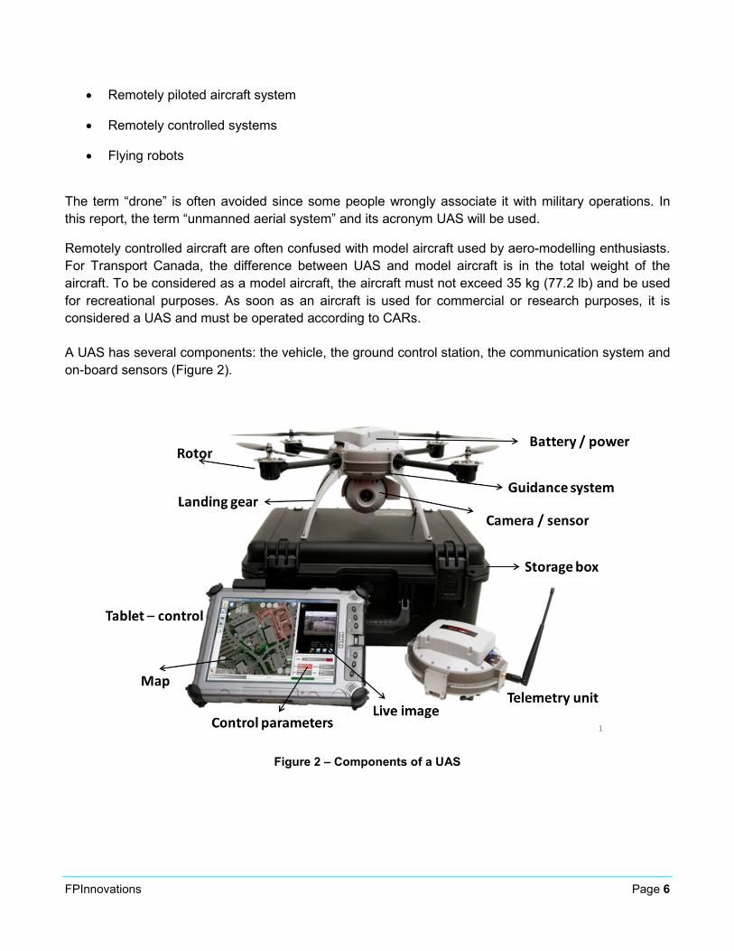
A UAS has several components: the vehicle, the ground control station, the communication system and on-board sensors (Figure 2).
Figure 2 – Components of a UAS
FPInnovations Page 7
The vehicle is composed of:
• the airframe that includes the fuselage, wings and the tail unit;
• the power plant that can be composed of one or several electric or combustion engines;
• electronic components (or avionics) which include the autopilot and communication system.
The autopilot is truly the brain of the UAS. It allows the aircraft to autonomously follow a predetermined route based on data from various sensors (GPS, inertial navigation system, altimeter, etc.). The ground control station can be more or less complex depending on the size of the UAS and type of the mission. It is able to plan the aircraft’s route and follow it in real time through a computer interface. Lastly, the communication system is the link between the aircraft and ground control station. It should be noted that some communication systems sold with commercial UAS elsewhere in the world are not compatible with Canadian radio-communication regulations. Therefore, it is important to ask Industry Canada for information before purchasing a UAS.
Classification and type of vehicles UAS vehicles come in different shapes and sizes. They can be unmanned aerial vehicles that carry out special missions. They can be remotely controlled or capable of flying on their own. The wide variety of aircraft on the market makes it difficult to classify vehicles.
For civilian applications, their classification is based primarily on the type of aircraft. In general, commercial applications involve small fixed-wing or vertical take-off and landing (VTOL) vehicles.
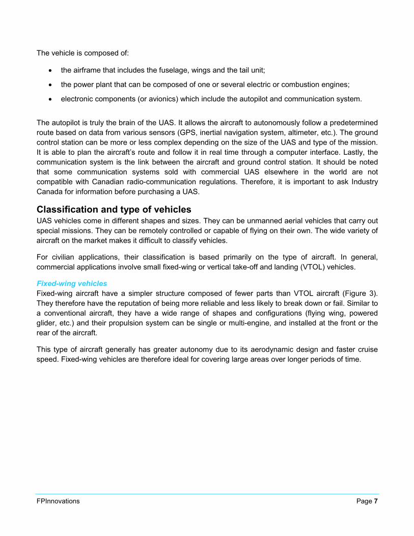
Fixed-wing vehicles Fixed-wing aircraft have a simpler structure composed of fewer parts than VTOL aircraft (Figure 3). They therefore have the reputation of being more reliable and less likely to break down or fail. Similar to a conventional aircraft, they have a wide range of shapes and configurations (flying wing, powered glider, etc.) and their propulsion system can be single or multi-engine, and installed at the front or the rear of the aircraft.
This type of aircraft generally has greater autonomy due to its aerodynamic design and faster cruise speed. Fixed-wing vehicles are therefore ideal for covering large areas over longer periods of time.
FPInnovations Page 8
Figure 3 - Example of a fixed-wing vehicle (UX5 from Trimble)
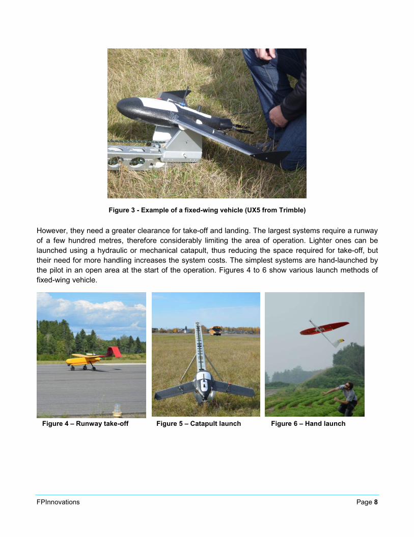
However, they need a greater clearance for take-off and landing. The largest systems require a runway of a few hundred metres, therefore considerably limiting the area of operation. Lighter ones can be launched using a hydraulic or mechanical catapult, thus reducing the space required for take-off, but their need for more handling increases the system costs. The simplest systems are hand-launched by the pilot in an open area at the start of the operation. Figures 4 to 6 show various launch methods of fixed-wing vehicle.
Figure 4 – Runway take-off Figure 5 – Catapult launch Figure 6 – Hand launch
FPInnovations Page 9
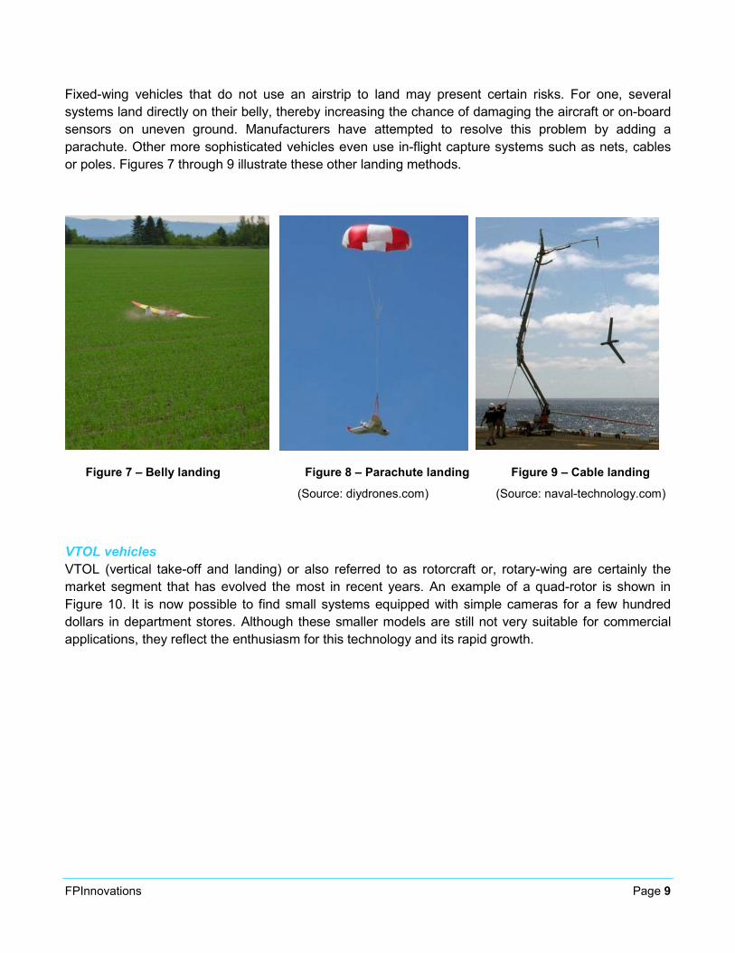
Fixed-wing vehicles that do not use an airstrip to land may present certain risks. For one, several systems land directly on their belly, thereby increasing the chance of damaging the aircraft or on-board sensors on uneven ground. Manufacturers have attempted to resolve this problem by adding a parachute. Other more sophisticated vehicles even use in-flight capture systems such as nets, cables or poles. Figures 7 through 9 illustrate these other landing methods.
Figure 7 – Belly landing Figure 8 – Parachute landing Figure 9 – Cable landing (Source: diydrones.com) (Source: naval-technology.com)
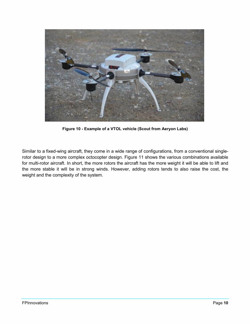
VTOL vehicles VTOL (vertical take-off and landing) or also referred to as rotorcraft or, rotary-wing are certainly the market segment that has evolved the most in recent years. An example of a quad-rotor is shown in Figure 10. It is now possible to find small systems equipped with simple cameras for a few hundred dollars in department stores. Although these smaller models are still not very suitable for commercial applications, they reflect the enthusiasm for this technology and its rapid growth.
FPInnovations Page 10
Figure 10 - Example of a VTOL vehicle (Scout from Aeryon Labs)
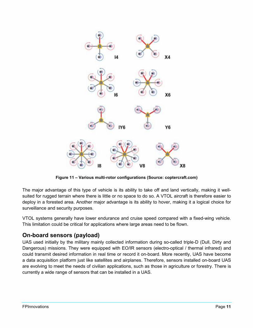
Similar to a fixed-wing aircraft, they come in a wide range of configurations, from a conventional single-rotor design to a more complex octocopter design. Figure 11 shows the various combinations available for multi-rotor aircraft. In short, the more rotors the aircraft has the more weight it will be able to lift and the more stable it will be in strong winds. However, adding rotors tends to also raise the cost, the weight and the complexity of the system.
FPInnovations Page 11
Figure 11 – Various multi-rotor configurations (Source: coptercraft.com)
The major advantage of this type of vehicle is its ability to take off and land vertically, making it well-suited for rugged terrain where there is little or no space to do so. A VTOL aircraft is therefore easier to deploy in a forested area. Another major advantage is its ability to hover, making it a logical choice for surveillance and security purposes.
VTOL systems generally have lower endurance and cruise speed compared with a fixed-wing vehicle. This limitation could be critical for applications where large areas need to be flown.
On-board sensors (payload) UAS used initially by the military mainly collected information during so-called triple-D (Dull, Dirty and Dangerous) missions. They were equipped with EO/IR sensors (electro-optical / thermal infrared) and could transmit desired information in real time or record it on-board. More recently, UAS have become a data acquisition platform just like satellites and airplanes. Therefore, sensors installed on-board UAS are evolving to meet the needs of civilian applications, such as those in agriculture or forestry. There is currently a wide range of sensors that can be installed in a UAS.
FPInnovations Page 12
Similar to other remote sensing platforms, their diversity makes them hard to classify since they can be grouped according to the portion of electromagnetic spectrum captured, the number of spectral bands, the way they operate (passive or active), etc. For this review, the sensors were divided into five categories: visible (EO), thermal infrared, multi-spectral, hyperspectral and LiDAR (Light Detection And Ranging).
Visible sensors Visible sensors, often called EO (electro-optics) in the field of UAS, are simple systems for acquiring images in the visible wavelength range [0.4 – 0.7 μm] of the electromagnetic spectrum. They are generally composed of a CCD (charged couple device) - or CMOS (complementary metal-oxide semiconductor) -type image sensor whose resolution can vary from a few thousand to several million pixels. Resolution is expressed in megapixels. They can be monochromatic or colour (three merged spectral bands: red – green – blue). They can be equipped with various optical devices (lenses and filters) that can change acquisition parameters such as the spatial resolution of ground images.
The use of mass-produced cameras (digital reflex and compact), such as those sold by Nikon or Sony, is increasingly widespread and these cameras offer quite acceptable image quality because of the flight’s low altitude. Their purchase price is relatively low, between $500 and $5000 depending on the model. Also available are industrial camera systems such as those developed by Prosilica, which retail for over $10,000 and must be used in combination with a control computer.
There is a multitude of areas where this type of sensor can be used, ranging from surveillance to forestry and civil engineering. Because of the extensive variety of sensors available, it is possible to find a solution that best meets the application’s requirements.
Thermal infrared sensors Thermal infrared sensors are widely used in the UAS industry. They work in the thermal infrared region, i.e., between 7.5 and 14 μm of the electromagnetic spectrum. Basic infrared cameras only provide a relative temperature gradient (cold to hot) within a frame, but more advanced cameras have radiometric calibration for temperature ranges and provide a temperature reading for each pixel. This type of sensor typically has a lower resolution. Systems available on the market have a maximum resolution of 640 x 480 pixels. Their purchase price ranges from $5000 to $10,000. It is worth noting that some systems, including those sold in the United States, are regulated by the International Traffic in Arms Regulations (ITAR) which can complicate their purchase.
This type of sensor is also used for a wide variety of applications. Initially intended for security and surveillance, they are now being used in agriculture to map the stress experienced by plants when short of water and in forestry to detect hot spots during forest fire suppression operations.
Multispectral sensors Multispectral sensors acquire data in several spectral bands that are in the visible (0.4 - 0.7 μm) and near infrared (0.7 – 1.1 μm) of the electromagnetic spectrum. These sensors are more specialized and their purchase price ranges from $7,500 to $15,000. Professional systems developed specifically for UAS are available, such as those designed by Tetracam or MicaSense, along with more homemade systems resulting from modifications made to a mass-produced camera.
FPInnovations Page 13
Some companies have a cheaper and effective alternate options, such as LDP LLC – MaxMax, PetaPixel, LifePixel, who specialize in converting regular cameras into specific spectral range ones.
Multispectral sensors are mainly used in agriculture, forestry or environment-related applications. The multiple spectral bands help in deriving vegetation indices, such as the normalized difference vegetation index (NDVI), that are frequently used as indirect parameters of biophysical status of vegetation.
Hyperspectral sensors Hyperspectral sensors are complex systems that acquire data within several dozens of spectral bands in the visible and infrared spectral regions. They can cost over $40,000. The current availability for these types of sensors is rather limited, because of their complexity and specific expertise to operate them besides having to analyze large volumes of data. Resonon and Rikola manufacture and distribute hyperspectral systems for use on UAS. These sensors are mainly used for applications in agriculture, forestry and the environment.
LiDAR systems As newcomers in the area of UAS, LiDAR systems represent a new direction in the development of on-board sensors in UAS. Very similar to radar or range systems, LiDAR technology works based on the principle of calculating the propagation time of a wave (visible or infrared) reflected or backscattered by a target. LiDAR sensors are “active” systems since they emit their own source of energy. Conversely, conventional optical sensors used in aerial photography are “passive” since they capture light from an external source of energy that is reflected by the imaged object.
Measuring the return time of the wave emitted by the sensor makes it possible to calculate the distance between the sensor and the target. Furthermore, an analysis of the properties of the returned laser beam, or echoes, makes it possible in certain situations to obtain additional information. For example, the wave emitted by an airborne LiDAR sensor will produce several echoes from a forest that will correspond to the ground, the top of the canopy and various intermediate layers. The LiDAR’s ability to penetrate through holes in vegetation to reach the ground makes it a very popular technology, especially in forestry.
Originally, LiDAR systems were too large and heavy to be installed on a small aircraft. However, in recent years some companies have developed miniature versions that can be for used on unmanned aircraft. Riegl’s VUX-1 and L’Avion Jaune’s YellowScan are some examples. These systems, although highly effective, are very costly (about $300,000 for the VUX-1) and could be a risky proposition, considering that UAS can have “hard” landings.
There are also less expensive LiDAR systems that were not initially designed to be installed on aircraft, but have good characteristics in terms of size and weight, so they can be integrated into a UAS. These systems retail for roughly $30,000 but must be installed with an inertial navigation system (INS) and control computer. The acquisition cost for all components is still far below the cost for professional systems, making them very attractive to developers. Several companies and organizations are currently working to integrate these into UAS.
FPInnovations Page 14
Equipment for navigational control In some cases, camera systems must be built into other components, such as a GPS, inertial navigation system (INS-GPS) or control computer. Equipment such as this can involve making a substantial investment since some INS-GPS can retail for several thousands of dollars. It should be pointed out that these components increase the total weight of the acquisition system, therefore reducing the platform’s autonomy.
UAS ground crew In addition to the aircraft’s physical components, the crew that pilots the UAS can be considered as a major ground component. The crew is composed of one or more individuals. For less complex systems, the crew can consist of one person who will be responsible for planning the mission, flying the UAS and handling the payload. However, for safety reasons, Transport Canada recommends that a second person also be present during missions so the pilot can fully focus on the flight. Complex systems may require a larger crew with several members. They will have well defined roles, such as the pilot, co-pilot, payload operator, spotter and operations manager.
3. LEGISLATION
Since commercial applications of UAS is relatively recent, aviation regulatory bodies in most countries around the globe have been slow to adapt. However, some countries such as France quickly adopted new regulations on the use of UAS, which are categorized based on the aircraft’s use and weight. In the United States, the Federal Aviation Administration (FAA) has been a bit reluctant in this area due to reasons of national security. Therefore, it authorizes UAS flights for commercial and research purposes only in one of the five approved test sites.
In Canada, UAS operations are regulated by Transport Canada under the Canadian Aviation Regulations (CARs). Section 602.41 of the CARs reads:
"No person shall operate an unmanned air vehicle in flight except in accordance with a special flight operations certificate or an air operator certificate."
Since November 2014, Transport Canada has relaxed this rule by introducing two new exemptions for certain operations involving very small (under 2 kg) and small (between 2 kg and 25 kg) UASs (hyperlink). The exemptions include a list of strict safety conditions that operators must respect at all times, including height restrictions, minimum distances from aerodromes and other hazards, as well as flight within specific airspace and visual line-of-sight. Anyone operating outside of these conditions will be required to apply for a Special Flight Operations Certificate.
SFOC applications may be complex depending on the type of aircraft and mission. Information on what an SFOC application involves is given further on in this document.
Given the phenomenal increase in the number of applications received, Transport Canada has had trouble meeting demand in its target time of 20 working days.
FPInnovations Page 15
It is therefore very important to apply early enough to make sure to respect the planned mission date. Right now, it is suggested to apply at least two months ahead of time. Furthermore, even for operations scheduled to take place in one day, it is important to plan on a few extra days, even weeks, in case bad weather or technical or logistical problems compromise operations.
Light UAS pilot training In its current form, Transport Canada’s regulations do not require UAS operators to have specific certified training. However, operator expertise is taken into account when evaluating SFOC applications and a pilot ground school is needed as an exemption condition for small UAVs. It is, therefore, highly recommended that operators have a minimum training on the various concepts related to using UAS (air law, weather, flight theory, radio communication protocols, etc.). Individuals or organizations interested in receiving training on operating a UAS can contact specialized companies. In the winter of 2015, Unmanned Systems Canada prepared a list of companies providing flying lessons specifically for UAS, which they intend to update regularly (hyperlink).
In addition to basic training on operating a UAS, it is sometimes possible to get customized training from the acquired platform manufacturer or distributor. The training would help operators have detailed knowledge on the aircraft’s specific characteristics. This type of training is not mandatory for operating a UAS, but it increases the application’s credibility at Transport Canada.
Information required for an SFOC This section describes the minimum information required when applying for an SFOC. Readers are invited to refer to the Transport Canada document for full details (hyperlink).
Operations crew
Contact information of applicant and operations manager The applicant is the company or person who owns the UAS. The operations manager is the person designated by the applicant who will be responsible for all operations and ensure that all SFOC obligations are respected. It is probably this person who will be contacted by Transport Canada if there is a problem. It is important to specify how this person can be reached at all times during flight operations.
Operators and definition of ground crew tasks For flights, a ground crew must be put together. It is important to describe each crew member’s tasks and their qualifications (e.g., radio operator course, pilot training and experience).
Description of operational plan
Type and purpose of operations Explain in broad terms the purpose of the operations for which the SFOC is requested.
FPInnovations Page 16
Dates and alternate dates of operations It is better to ask for a period of several weeks to ensure that weather conditions are ideal for operations and also in case unforeseen circumstances arise. It is also possible to propose alternate dates if flights cannot take place during the initially planned period. In all cases, SFOC holders must send a notice to Transport Canada two days prior to operations to confirm operations. The notice must include all operator contact information and the mission’s description again.
Times of the proposed operations In general, flights must take place one hour after sunrise and stop one hour before sunset.
Overflight permission UAS users must have permission from each of the owners of the properties overflown. Letters must be enclosed with the application.
Insurance Applicants must show they have third party liability insurance for operating the UAS.
Weather conditions Users must specify the weather limits for operating the aircraft. They must also specify the method or equipment that enables them to check if the aircraft’s limits are respected and if not what procedure will apply.
Description of flying areas UAS use is subject to restrictions in urban centres and built-up areas, and near airports and forest fire fighting operations. Certain key conditions apply to all operations under an SFOC, one of which requires that the operator only fly the UAS “over areas that would permit a safe landing on the surface without hazard to persons or property in the event of any emergency requiring immediate descent.”
If the terrain is known, it is better to describe and locate each area. The plan must be to scale and include the following information:
• Altitudes and routes to be used on the approach and departure to and from the area where the operation will be carried out;
• The location and height above ground of all obstacles in the approach and departure path to the areas where the operation will be carried out;
• Coordinates of the limits of the area where the operation will be carried out;
• Any other information to ensure that operations are conducted safely.
Flight operations Users must describe how the aircraft’s flight will be conducted, including type of take-off, UAS operational mode, flight plan, duration, type of landing, expected altitudes, acquisition campaign along with the radius that will enable the crew to maintain constant visual contact with the UAS.
FPInnovations Page 17
Aircraft description
Technical characteristics The applicant must describe the aircraft’s technical characteristics and performance. To provide as much information as possible, it is suggested to enclose the operations manual with the application.
UAS operational mode If the aircraft is used with a transmitter/receiver, it is necessary to describe the transmitter’s characteristics and how communication will be established with the aircraft.
Emergency contingency plans
Person responsible for contingency plans Assign a person to be responsible for safety and indicate contingency plans in case problems arise during an emergency.
Security plan "Safe flight is Transport Canada’s primary concern when issuing the SFOC." Transport Canada
Unmanned aircraft operators must ensure that no non-essential persons for operations are present in the flying area during operations. They must indicate what measures will be taken if people are in the landing and take-off area or if another aircraft is present in the designated flying area. Where necessary, if the operator is not able to contact the other aircraft, the UAS must make an emergency landing. It will also be necessary to explain what procedure is to be followed if communication is lost between the aircraft and the ground control station or if the GPS signal is lost.
Emergency contingency plan The emergency contingency plan must be described in the same way it will be communicated to the control tower to inform it of a situation.
Emergency services SFOC applicants must confirm and show they are aware of available emergency services (fire and police departments) near the flying area. They must also inform these departments of the operations scheduled to take place in the region, as soon as they are approved with the SFOC. They must have the numbers to reach the municipality’s different emergency services.
Relations with other regional structures It will be important to send operation-related information to the region’s various airports and flight operators.
FPInnovations Page 18
4. TECHNOLOGY WATCH
A technology watch was conducted by the Centre de Géomatique du Québec (CGQ) on platforms, sensors and imaging software to identify currently available Unmanned Aerial Systems (UAS). A comparison table was prepared to describe each category. These tables may be used to take a closer look at the equipment available and determine which solutions are best suited for forest operations. They are available on the FPInnovations web site (hyperlink). Readers should note that the review took place in November 2014 and should remember that the technology evolves very quickly in this field.
Platforms Over fifty UAS platforms were identified and documented in the comparison table. The table includes many characteristics to clearly highlight differences among the aircraft. The following main criteria were selected, considering UAS use in a forestry application:
• Autonomy;
• Weight;
• Payload;
• Power supply;
• Acquisition cost;
• Ability to operate in limited space;
• Ease of handling;
• Aircraft stability.
FPInnovations Page 19
Sensors (cameras) There is a very broad range of sensors that can be installed on UAS. In this review, close to 70 sensors were identified. They were divided into five categories: visible (EO), thermal infrared, multispectral, hyperspectral and LiDAR. It is worth noting that several UAS systems have sensors that are part of the aircraft and cannot be interchanged. These systems are generally more expensive, but are easier to operate. Conversely, there are sensors specifically developed for use on a UAS, but not necessarily for a particular model. The comparison table identifies all types of sensors regardless of their level of integration on one or more platforms. The sensor comparison was based on use in forest operations. The main criteria were:
• Size and weight;
• Level of integration (modifiable or not);
• Spatial resolution (size and number of pixels);
• Autonomy (need for a control computer or not);
• Acquisition cost;
• Types of possible operations.
Image processing – 3D modeling software Once images are acquired, they must be stitched to make them into a contiguous image and processed to extract as much information as possible. Processing is done with specialized software that is expensive to purchase (depending on the functionalities) and can be complex to work with. It should be noted that this software, just as UAS and sensors, requires a certain level of expertise and can present a major challenge to people lacking the necessary skills. Furthermore, the image processing step is often overlooked, but it can represent the largest part of the work flow. It is therefore important to choose an effective and efficient software solution.
In recent years, new image-processing software has appeared on the market that is well suited to images acquired by UAS. The comparison table shows some twenty software options to help find the best solution. The review criteria were:
• Ease of use;
• User interface;
• Technical assistance;
• Acquisition cost;
• Features;
• Training.
FPInnovations Page 20
5. SUGGESTED SYSTEM SETUP
The technology watch and analysis conducted as part of this review contribute in identifying system requirements for setting up a UAS suitable for forestry applications. A few key criteria are suggested below.
Selecting a system VTOL-type aircraft do well in forests considering the major constraint of limited space to take off and land. This type of aircraft can take off and land in a space as small as 2 m x 2 m.
The weight of the system is also a key factor to consider. One person must also be able to transport the aircraft and its components since operations do not always take place near roads. The UAS must therefore be lightweight and compact.
In addition, the system must be relatively easy to control. Individuals who will be asked to operate this aircraft must be self-sufficient and capable of preparing the mission, operating the device and repairing it if it breaks. This last element is important since the mission site and the organization’s office may be far apart and, as a result, it is highly likely that operators will need to make repairs.
Low-cost, off-the shelf consumer market UAS offer potential solution for reconnaissance and monitoring applications, but lack features in producing quality mapping outputs.
Training Operator training is crucial. Formal training is becoming easier to acquire as companies providing flying lessons specifically for UAS are quickly developing. Operators must also be trained by the manufacturer or distributor for the specific operation and maintenance of the acquired aircraft.
Data management Images from a UAS platform are acquired at a fairly low altitude with high resolution. Therefore, these systems produce remarkably high volumes of data and pose great challenges in data management, both for post-processing and archiving. For instance, a 2-ha forest captured in 100 RGB still images of high resolution (better than 1 cm per pixel) at a 60-m altitude would result in a data size of nearly 3 GB. Video recordings of surveillance are usually larger than still captures of the same area.
For a better performance, most post-processing software recommend basic, advanced and extreme configurations of the hardware. For example, Agisoft recommends a basic configuration with a 32GB RAM, a Quad-core Intel CPU, any LGA 1155 model with 4 DDR3 slots motherboard and NVDIA GeForce GTX 780 GPU to be able to process large image datasets. On the extreme end, one can use an Intel Xeon workstation.
Depending on the amount of data that will be generated in a given year and the requirements of future use of this data, a suitable storage solution should be considered for archiving the raw and processed data. Several solutions are offered for large volume of data in the market from local storage to cloud services.
FPInnovations Page 21
Quality of the outputs Quality of a photo mosaic or map output from a photo mosaic can be measured in several ways – amount of details present, relative or absolute scale within the map, positional / vertical accuracies, etc. High level of details can be obtained from sensors with high sensitivity to light or high dynamic range (a ratio of maximum to minimum light intensity). A high mega-pixel sensor does not necessarily provide a higher quality output. Capturing of details is dependent also on external factors present during the acquisition, especially light conditions, weather and the wind stability of the platform. Bright illumination with minimal shadows can provide a good quality output, which in turn will help in building good image-mosaics and 3D models. Positional (geo-location) as well as vertical accuracies are related to the quality of the GPS and IMU present on-board the UAS, and the ability of the post-processing software to use them in the models.
6. CONCLUSION
This purpose of this review was to introduce UAS technology to the forest sector, including platforms, on-board sensors and regulations governing unmanned aircraft operations in Canada. A technology watch was also conducted on platforms, sensors, and imaging software. It should be noted that UAS technology is evolving very quickly and that in a few months, new solutions may appear on the market. The technology watch was therefore only a snapshot in time. The results are provided in table format that can be consulted on FPInnovations’ website. Comparison tables are available to facilitate the analysis of solutions adapted to a forest operations context.

Québec 319, rue Franquet
Québec QC
Canada G1P 4R4
T 418-659-2647
Head Office Pointe-Claire 570, Saint-Jean Blvd
Pointe-Claire, QC
Canada H9R 3J9
T 514 630-4100
Vancouver 2665 East Mall
Vancouver, BC.
Canada V6T 1Z4
T 604 224-3221
© 2014 FPInnovations. All rights reserved. Copying and redistribution prohibited. ® FPInnovations, its marks and logos are trademarks of FPInnovations


![FY18 RWDC State Unmanned Aerial System Challenge ... · Unmanned Aerial System Challenge: Practical Solutions to ... , Real World Design Challenge ... , unmanned aerial vehicle [UAV])](https://img.pdfslide.us/doc/110x75/5ae85cfb7f8b9a8b2b8fe5e5/fy18-rwdc-state-unmanned-aerial-system-challenge-aerial-system-challenge-practical.jpg)