Embed Size (px)
Citation preview

University of Michigan Preliminary Design Review
Project Wolverine: Butterfly Valve Drag Variation for Mile High Apogee
2011-2012
University Student Launch Initiative
Department of Aerospace Engineering University of Michigan
3012 Francois-Xavier Bagnoud Building 1320 Beal Avenue
Ann Arbor, MI 48109-2140

Table of Contents
1. Summary ................................................................................................................................... 5
1.1 Team Name and Location ................................................................................................ 5
1.2 Administrative Staff ........................................................................................................... 5
1.3 Launch Vehicle Summary ................................................................................................ 5
1.3.1 Vehicle Size ................................................................................................................ 5
1.3.2 Motor Choice ............................................................................................................... 5
1.3.3 Rail Size ....................................................................................................................... 5
1.3.4 Recovery System ....................................................................................................... 5
1.4 Science Experiment .......................................................................................................... 5
2. Changes Made Since Proposal ............................................................................................. 6
2.1 Changes Made to Launch Vehicle .................................................................................. 6
2.2 Changes Made to Science Experiment .......................................................................... 6
2.3 Changes Made to Activity Plan ....................................................................................... 6
3. Vehicle Summary ..................................................................................................................... 6
3.1 Selection, Design, and Verification of Launch Vehicle ................................................ 6
3.1.1 Mission Statement and Requirements .................................................................... 6
3.1.2 Milestone Schedule .................................................................................................... 7
3.1.3 Butterfly Valve Design ............................................................................................... 8
3.1.4 Subsystems and Performance Characteristics ................................................... 11
3.1.5 Risk Assessment ...................................................................................................... 14
3.1.6 Maturity of Design .................................................................................................... 21
3.1.7 Dimensional Drawing of Assembly ........................................................................ 21
3.1.8 Electrical Schematics for Recovery ....................................................................... 23
3.1.9 Mass Statement ........................................................................................................ 24
3.2 Recovery Subsystem ...................................................................................................... 25
3.3 Mission Performance Predictions ................................................................................. 27
3.3.1 Mission Performance Criteria ................................................................................. 27
3.3.2 Flight Profile Simulations ........................................................................................ 28
3.3.3 Stability....................................................................................................................... 30
3.3.4 Kinetic Energy of Launch Vehicle .......................................................................... 31
3.3.5 Drift of Launch Vehicle ............................................................................................ 31
3.4 Interfaces and Integration .............................................................................................. 32
3.4.1 Integration Plan ........................................................................................................ 32
3.4.2 Internal Interfaces .................................................................................................... 32
3.4.3 Ground Interfaces .................................................................................................... 32
3.4.4 Ground Launch System Interfaces ........................................................................ 32
3.5 Launch Operation Procedures ...................................................................................... 32
3.5.1 Launch System and Platform ................................................................................. 32
3.5.2 Launch Procedures .................................................................................................. 33
3.6 Safety and Environment ................................................................................................. 34
3.6.1 Safety Officer ............................................................................................................ 34
3.6.2 Failure Modes ........................................................................................................... 34
3.6.3 Personnel Hazards .................................................................................................. 37
3.6.4 Environmental Concerns ......................................................................................... 39
4. Payload Criteria ...................................................................................................................... 40
4.1 Selection, Design, and Verification of Experiment ..................................................... 40
4.1.1 Review of Experiment .............................................................................................. 40
4.1.2 Aerodynamic Analysis – Butterfly Valves .................................................................. 40
4.1.3 Mesh Type and Sizing ................................................................................................. 40
4.1.4 Moment Concerns ........................................................................................................ 42
4.1.5 Alternate Design – Linear Flaps .................................................................................. 43
4.2 Concept Features and Definition .................................................................................. 45
4.2.1 Creativity and Originality .......................................... Error! Bookmark not defined.
4.2.2 Significance ................................................................ Error! Bookmark not defined.
4.2.3 Level of Challenge .................................................... Error! Bookmark not defined.
4.3 Science Value .................................................................................................................. 46
4.3.1 Experimental Objectives ......................................................................................... 46
4.3.2 Experiment Success Criteria .................................................................................. 46
4.3.3 Method of Investigation and Test Variables ......................................................... 46
4.3.4 Relevance of Expected Data and Progress ......................................................... 53
4.4 Safety and Environment for Experiment ...................................................................... 56
5. Activity Plan ............................................................................................................................ 56
5.1 Budget ............................................................................................................................... 56
5.2 Schedule and Timeline ................................................................................................... 57
5.3 Educational Engagement ............................................................................................... 60

6. Conclusion .............................................................................................................................. 60

1. Summary
1.1 Team Name and Location The University of Michigan Rocket Engineering Association (MREA) from Ann Arbor, Michigan proposes Project Wolverine.
1.2 Administrative Staff MREA‟s administrative staff member is Iain D. Boyd. The team mentor is Matt Schottler and he holds a Tripoli Level 2 Certification.
1.3 Launch Vehicle Summary The flysheet for Project Wolverine can be found on our website (http://www.umich.edu/~mrea/).
1.3.1 Vehicle Size Outer diameter: 5.52” Inner diameter: 5.36” Total length: 95.00”
1.3.2 Motor Choice The projected motor type for the vehicle is a Loki L1482-SM motor (76mm diameter). This determination was made based on a Rocksim simulation and is subject to change.
1.3.3 Rail Size Project Wolverine will use 2 buttons and launch from a 72x1x1 in3 rail.
1.3.4 Recovery System To ensure a safe recovery, Project Wolverine will separate twice during the descent. At apogee Project Wolverine will undergo a drogue-less separation which will slow the descent. Then, depending on launch conditions, the main parachute will be deployed between 1000ft and 600ft to decelerate the launch vehicle to a safe speed for touchdown. Both ejection charges will be ignited by the flight computer.
1.4 Science Experiment The projected experiment for MREA‟s Project Wolverine is two butterfly valves (separated 180 degrees) that vary pressure drag. During the ascent, the butterfly valves will be actuated based on real time data from GPS, flight computers, and possibly a pitot tube to vary the pressure drag on the rocket. The goal of this experiment is to put a high impulse motor in the rocket that ensures the rocket will reach at least one mile at apogee, yet have the rocket only reach one mile at apogee due to the increased drag from the butterfly valves.
2. Changes Made Since Proposal
2.1 Changes Made to Launch Vehicle The launch vehicle has increased in both length and diameter, and there will be two butterfly valves implemented in the design. The valves will be placed inside cans on the outer diameter of the rocket and centered on two of the four fins so that they are 180 degrees apart. We have also decided to upgrade from phenolic tubing to blue tube for more structural support.
2.2 Changes Made to Science Experiment No changes have been made to the science experiment.
2.3 Changes Made to Activity Plan The activity plan has been altered so that parts can be ordered following PDR. This will allow construction and testing to be completed before CDR. The activity plan is also more detailed because the major design issues have been resolved.
3. Vehicle Summary
3.1 Selection, Design, and Verification of Launch Vehicle
3.1.1 Mission Statement and Requirements This mission of our USLI project is to prove the feasibility of a model rocket control system that continuously takes in sensor data during flight and actuates a physical mechanism, altering the rocket‟s coefficient of drag in order to reach exactly one mile in altitude.
Requirements
1. The rocket must reach as close to a mile high as possible. 2. Any actuation of the drag mechanism at any point during flight must not
have a significant, negative effect on the stability of the vehicle. 3. The control system must be able to make multiple physical adjustments to
the rocket, on the order of 10 or 20, which all occur after engine burnout and before apogee.
4. The launch vehicle must respond to these physical changes in a manner consistent with our calculations so that the control system can identify and execute a correct behavior given specific data from the sensor(s).
5. The data detailing the behavior of the control system must be collected and analyzed after flight in order to better calibrate the control algorithm.
6. The recovery system must minimize the drift of the vehicle away from the launch point and maximize the probability of recovering the vehicle with all components intact and functional.
Mission Success Criteria Our mission will be considered a success if:

1. The implementation of the control system and variable drag mechanism puts the vehicle at an altitude closer to one mile than the altitude achieved by the same vehicle without these systems.
2. The vehicle reaches a maximum altitude of 5280 feet ± 100 ft. 3. The entire rocket is recovered safely and is in a condition suitable for re-
launch.
3.1.2 Milestone Schedule
December 2011 5 – 14 PDR Presentation
1 – 15 Preparation and Development of Ground Tests 15 – 22 Order and Acquisition of Parts 14 – Jan. 4 Final Exams and Winter Break January 2012
4 – 22 Critical Design Review Development 4 – 15 Preliminary Subsystem Construction and Ground Tests 23 CDR Completed 23 – Feb. 10 Construction and Preliminary Integration
February 2012 1 – 10 CDR Presentation 1 – 15 Systems Ground Tests
16 – 29 Construction of Final Vehicle Subsystems March 2012
1 – 15 Final Vehicle Assembly and Integration 1 – 26 Flight Readiness Review Development 26 FRR Completed
TBD Test Flight of Final Vehicle April 2012
2 – 11 FRR Presentation 18 Travel to Huntsville 19 – 20 Flight Hardware and Safety Check 21 Launch Day 22 Travel Home
23 – 30 Final Exams May 2011:
1 – 6 Post-Launch Assessment Review Development 1 – 6 Launch Evaluation and Data Analysis 7 PLAR Completed

3.1.3 Butterfly Valve Design Our USLI 2011-2012 rocket is a fairly traditional rocket with the exception of two external body tubes (Blue Tube material) that run along the main airframe from the tail of the rocket to a point some 35 inches forward of the tail. Inside these two body tubes several inches aft of the top is a butterfly valve, which rotates to control the airflow through the rest of the tube. By changing the position of these butterfly valves, we induce or reduce the stagnation pressure on the valve and therefore the total drag on the rocket, allowing us to reach exactly a mile in altitude. There are four fins on the rocket, each 90 degrees apart. Two opposite fins attach directly to the airframe and the other two attach to the airframe through one of the body tubes. Inside the rocket is the avionics bay, or AvBay, which houses our payload (the control system for the butterfly valves) and all the flight avionics. Forward of the AvBay is the main parachute. The critical dimensions of the rocket are as follows: Length: 81.00 inches Airframe Outer Diameter: 5.52 inches Inner Diameter: 5.36 inches External Body Tubes Length: 35.00 inches Inner Diameter: 1.50 – 2.55 inches Outer Diameter: 1.62 – 2.67 inches The diameters of the external body tubes are not set yet due to uncertainties of exactly how much drag the control system needs to be able to produce. Once more computational fluid dynamics testing is done on a virtual model of the rocket, these diameters will fall into place. We chose to build a rocket with an inner diameter of over 5 inches in order to facilitate access to the payload and avionics bay. Last year our rocket had an inner diameter of just less than 4 inches, and it was difficult to install and routinely make adjustments to the electronics bay. A larger diameter will allow for easier and more frequent access to the AvBay. The external body tubes are 35 inches long in order to account for the motor assembly at the aft of the rocket. The mechanism that rotates the valves is on the same plane as the valves, so the tubes must extend a good 5 or 6 inches above the end of the motor assembly in order to give enough space to the rotating mechanism inside the rocket. The tubes extend all the way down to the aft of the rocket so that the airflow exiting the tubes does not interact with the fins. Since these tubes and accompanying control system contribute a considerable amount of weight to the rocket, the airframe continues forward for another 35 inches, culminating with a nose cone, to make sure that the center of gravity is well forward of the center of pressure. This gives our rocket a healthy stability margin.

One of the most important and unique systems of our 2011-2012 USLI project is the control system, which includes an altitude sensor, a microprocessor, a digital servo motor, and the mechanical drag mechanism. The drag mechanism is actuated multiple times during flight by the microprocessor to either increase or decrease the drag on the rocket. Over the past couple of months, our team came up with many different options for the design of this drag mechanism. These included a retractable nose cone, drag flaps, a “drag skirt”, and butterfly valves, among many others. In order to choose one of the options, we considered the required characteristics of this system. The drag mechanism must be:
1. Stable. It is absolutely critical that our drag mechanism does not adversely affect the stability of the rocket at any time during flight, even in its neutral configuration during engine burn. It cannot create any moments that would cause the rocket to significantly deviate from an otherwise straight-up trajectory.
2. Fast. In order to get as close to a mile as possible, we need to be able to adjust the mechanism multiple times in between engine burnout and apogee. If it takes too long time to actuate the drag mechanism, the sensor data that the microprocessor uses to calculate the position of the mechanism becomes obsolete by the time our mechanism finally gets into position.
3. Precise. Due to the tremendous speeds that the rocket reaches, especially immediately after engine burnout, the mechanism needs to be extremely precise in its movement. Since a small mechanical deviation may lead to a large deviation in the drag and resulting altitude of the rocket, the physical system must move to exactly the position determined by the microprocessor.
4. Highly variable. To a certain extent, we want the range of drag coefficients produced by our drag mechanism to be as wide as possible. This allows us to account for a wide range of atmospheric conditions and different scenarios that our rocket might encounter during flight.
5. Consistent. For a specific orientation, the mechanism must affect the flight of the rocket in a specific way, regardless of the current speed or altitude of the vehicle. If the drag mechanism affects the vehicle differently each time, the control system will be far less effective as a whole.
Based on these criteria, we chose to implement the butterfly valve design, which has the following physical characteristics that are relevant to our launch vehicle. See Figure
1.
1. Two 2”- diameter butterfly valves mounted inside separate body tubes on opposite sides of the main airframe. The rotational axis of both butterfly valves is the y-axis of the rocket.

2. A single, digital servo mounted in the center of the main airframe on the same horizontal plane as the two butterfly valves. This servo‟s rotational axis is the z-axis of the rocket.
3. Two “driveshafts” that connect both valves to the servo. 4. Two 2”- diameter butterfly valves mounted inside separate body tubes on
opposite sides of the main airframe. These two body tubes are parallel to the airframe and extend upwards roughly three feet from the tail of the rocket. The rotational axis of both butterfly valves is the y-axis of the rocket.
5. A single, digital servo mounted in the center of the main airframe on the same horizontal plane as the two butterfly valves. This servo‟s rotational axis is the z-axis of the rocket.
6. Two “driveshafts” that connect both valves to the servo.
As compared to the other designs that we considered, the butterfly valve design has possibly the largest physical “footprint” on the launch vehicle, as it involves attaching two ~3ft. long, 2”-diameter tubes
Figure 1: Drag Variation Ideas Considered for Project Wolverine

As compared to the other designs that we considered, the butterfly valve design has possibly the largest physical “footprint” on the launch vehicle, as it involves attaching two ~3ft. long, 2”-diameter tubes to the airframe. As a result of these two airflow tubes, we decided to equip our rocket with four fins instead of three. Two fins are attached directly to the airframe at points between the two body tubes, and the other two fins are attached to the airframe through the two body tubes. This decision was made for a couple different reasons.
1. There were concerns for the stability of the rocket if it only had three fins.
Since the body tubes housing the butterfly valves are exactly 180 degrees apart from each other on the airframe, there is no way to desirably arrange three fins so that the configuration is symmetric along multiple axes. Either there are two fins on one side of the body tubes and one on the other (FIGURE), or there is one fin through one body tube and none through the other (FIGURE). Another stability concern related to the fact that these body tubes might interfere with the otherwise laminar airflow around the fins at the aft of the vehicle, thus decreasing the fins‟ effectiveness in correcting the flight path of the rocket.
2. Having a fin extend from the airframe through both body tubes increases the structural integrity of the launch vehicle. Since both the airframe and the body tubes are cylinders, attaching the two parts together along the longitudinal axis may be difficult because of the minimal contact surface area. A rigid fin connecting the two helps ensure that the tubes adhere securely to the airframe to form a cohesive vehicle.
Having four fins on the rocket in the configuration previously described addresses both of these issues. The rocket is symmetric along two axes – the one that splits both body tubes in half and the one that lies 90 degrees in between both tubes. Because two fins extend outside of the body tubes, they are more immune to the turbulent or partially turbulent flow that may exist in the area between the two body tubes. As the flow outside the body tubes figures to be more laminar, having more fins in this flow effectively aids the stability of our rocket. Structurally, a configuration with four fins allows for the construction of a vehicle that has a fin through both of the body tubes, increasing our confidence in the durability of the rocket.
3.1.4 Subsystems and Performance Characteristics Aerodynamics The aerodynamics subsystem is responsible for how the rocket interacts with the airflow during flight. This includes any moments, drag, or instability created by the interaction of the launch vehicle and the gases flowing around it. More specifically, the aero team will run a CFD (Computational Fluid Dynamics) simulation on a virtual model of the rocket to verify that it is stable under all drag mechanism orientations. This CFD simulation will also serve to provide preliminary quantitative values for the amount of drag that the control system will be able to induce during different points in flight. Evaluating this data

is key to the selection of appropriately sized external body tubes and butterfly valves as well as implementing an accurate control system. Once dimensions have been solidified, the team will begin construction of a full-size rocket half-body. This will be tested in a wind tunnel at various speeds and drag configurations to verify that
1) the drag values from CFD are legitimate, 2) the drag values are sufficient to effectively guide the rocket to exactly a mile
in altitude, and 3) the rocket is stable in all drag configurations at various speeds.
Controls A crucial subsystem, controls is responsible for designing, writing, and implementing the code that defines the control algorithm for our drag mechanism. Basically, this subsystem must construct a reliable “maximum altitude” algorithm given only the current speed and height of the rocket. From there, this calculated height is compared to the desired altitude of one mile and the algorithm decides how much it needs to increase or decrease the drag on the rocket. An important characteristic of the controls subsystem is that it must take into account that no energy can be added into the vehicle after engine burnout. In other words, the algorithm must not ever increase the drag to a point where the rocket is projected to reach an altitude under a mile with the drag mechanism in the neutral configuration (no added drag). That being said, the controls subsystem will be able to account for both upward and downward perturbations of the launch vehicle during flight. It will also strive to adjust the drag as many times as possible before apogee to ensure that the rocket gets as close to a mile as possible. The algorithm will eventually be written in the C++ language. Once the algorithm is complete, we will statically test it by manually feeding it different inputs and observing the resulting outputs. Subsequent verification of the controls subsystem will take place in a pressure chamber, which can simulate different altitudes for our pressure-based altimeter. Testing will be done on the entire control system, which consists of the altimeter, the microprocessor running the algorithm, and the digital servo controlling the butterfly valve. Evaluation of the algorithm will be based on whether it outputs the correct signal to the servo given a variety of simulated velocities and altitudes.
Data Handling Data Handling includes all the exchanges of data that occur between various devices in the rocket during flight. Specifically, the subsystem must ensure that the altimeter, microprocessor (running the control algorithm), and electronically-actuated drag mechanism can communicate quickly and effectively. Performance characteristics include handling differences in clock speeds and interfacing between different devices.

Evaluating the Data Handling subsystem will be done both statically and dynamically. Once the control algorithm is finished, all three hardware components can be hooked together and run at a constant pressure to verify that all devices integrate properly. After it is certain that communication has been successfully integrated, the system will be tested in the pressure chamber, as previously described under the Controls subsystem above. Flight Avionics This is the subsystem that is responsible for the design and/or selection of all hardware required by the control system. Specifically, the flight avionics include an altimeter to
measure altitude and near-instantaneous velocity (
position
time), a microprocessor that
can run the control algorithm, and a digital servo that actuates the drag mechanism. Put together, these three devices comprise the hardware that controls the rocket‟s velocity and final altitude during flight. Initial verification of each hardware component will be done separately. Specifically, the servo can be easily tested using a Digital Multimeter and an established control source code. The microprocessor will be tested on multiple algorithms and inputs. Placing the altimeter in a pressure chamber will allow us to affirm its integrity. Further verification of the flight avionics will occur in parallel with the pressure chamber testing of the control algorithm, as the control algorithm is essentially the brain behind the muscle of the avionics. Recovery Avionics Recovery Avionics are limited to any hardware that is used to either separate the launch vehicle or eject a parachute. This hardware includes a flight computer and a redundant altimeter that fire “e-charges” (black powder ignited by a surge of current) at pre-set altitudes to execute specific flight events. Performance characteristics specifically include firing a charge to separate the rocket at apogee and then igniting a second charge at 500 feet to separate the launch vehicle again and eject the main parachute during descent. Testing the Recovery Avionics will occur in a similar manner to the methods outlined above in the section on Flight Avionics. A Digital Multimeter will also be used to ensure that the devices supply enough current to successfully ignite an e-charge. Propulsion The propulsion subsystem must select an appropriate engine for the rocket. Because the control system can only slow the rocket down from its neutral trajectory, this motor must put the rocket safely above one mile. Depending on the drag constraints of our control system, however, the engine must not put the rocket too much over a mile. The subsystem must also design a method for retaining the engine in the launch vehicle in such a way that facilitates loading and unloading of the engine before and after launch while ensuring the security of the motor assembly during and after burn.

Verification of engine choice will be performed by both software programs like RockSim as well as hand calculations. We will use both of these methods to ensure to a good degree of certainty that the rocket would reach an altitude of above one mile without actuation of the control system. Evaluation of the motor retention mechanism will occur both after construction of the rocket half-body and after observing the performance of the mechanism during a test launch. Structures Structures is responsible for optimizing and integrating the materials that make up our physical launch vehicle. These include external features like the airframe and the fins as well as all interior members, such as the mechanical components of the drag mechanism and the bay that houses the electronics. During the flight of the rocket, all structures must be resistant to extensive deformation and protect the components that they house from harm, such as undesirable gases formed by the combustion of the black powder e-charges. The materials that make up the vehicle will be verified using software to simulate various stresses and loads on each different component.
3.1.5 Risk Assessment The figure below shows the risk matrix for the MREA rocket. The matrix plots the most likely foreseeable failure events on likelihood versus impact. The following tables (Table 1-8) below details possible failure events for various aspects of the project, including boost phase of flight, the control subsystem, environmental concerns, launch operations, personnel hazards, scheduling and planning risks, the recovery subsystem, and the structural integrity of the vehicle. Additionally, these tables include mitigation plans, meant to decrease likelihood and impact of the possible risks.
Risk ID Risk Item Mitigation Plan Likelihood Impact Risk Index
BOOST-01
Rocket Engine Failure
Extra igniters will be on hand to replace a failed engine.
1 2 2
BOOST-02
Motor Becomes Dislodged During Flight
Motor will be securely attached to rocket via a retention system.
2 2 4
Table 1: Failure Modes for Launch Phase of Flight
Risk ID Risk Item Mitigation Plan Likelihood Impact Risk Index
CONTROL-03
Control System Deployment Failure
The flaps will be aligned in the upright position on the pad so that they will act as fins if computer fails.
3 3 9

CONTROL-04
Microcontroller in-flight failure
Extensive testing of the flight computer system will be performed, including static tests, wind tunnel tests, and flight tests.
3 4 12
CONTROL-05
Actuator Servos or Gearbox Jams
The servo system and gearbox will be verified extensively before launch under static loads, wind tunnel tests, and test flights.
2 3 6
CONTROL-06
Only a Single Flap Deploys
A correction mechanism will be programmed into the control algorithm to return single flap to the upright position if detected. Extensive testing on controls will also be performed.
2 5 10
CONTROL-07
Vehicle becomes Unstable During Flight
Verification of stability will be performed through CFD analysis, wind tunnel tests, and test launches.
2 5 10
Table 2: Failure Modes for Controls Subsystem
Risk ID Risk Item Mitigation Plan Likelihood Impact Risk Index
ENVIRON-08
Extreme Windy Conditions, Heavy Rain, or Snow
Launch will be scrubbed and rescheduled.
3 3 9
ENVIRON-09
High Winds
Parachute deployment altitude will be lowered to decrease drift distance. In the case of test launch, smaller motor may be used to reduce overall altitude.
4 2 8

ENVIRON-10
Mild Rain
The rockets exterior, to avoid wetting of the ignition strips, covers the ignition system. The exterior structure of the rocket is durable enough to withstand light rain.
3 1 3
ENVIRON-11
Cloudy Day
GPS recovery system will help locate rocket. Launch may be delayed or a smaller motor may be chosen to reduce chance of loss of launch vehicle.
3 1 3
ENVIRON-12
Mild Wind
The angular orientation of the rocket will be adjusted according to launch day wind conditions.
5 1 5
Table 3: Failure Modes for Environmental Concerns
Risk ID Risk Item Mitigation Plan Likelihood Impact Risk Index
OPS-13
Vehicle Damaged During Transport
The vehicle will be transported in a separate compartment to ensure it will not be damaged by spare parts.
1 5 5
OPS-14 Ejection Charges Ignite Before Launch
Ejection charges will not be armed and igniters will not be installed until vehicle is on launch pad to prevent a premature launch. A switch on the exterior of the rocket will arm the flight computers after the rocket is on the pad.
1 4 4
OPS-15
Spectator is Harmed by Launch Vehicle
Announcements will be made to warn spectators that a vehicle is being launched and spectators will be positioned a safe distance from the launch pad.
1 5 5

Table 4: Failure Modes for Launch Operations
Risk ID Risk Item Mitigation Plan Likelihood Impact Risk Index
PERS-16
Epoxy toxic fumes, skin irritation, eye irritation
Team members will work in well-ventilated areas, wear face masks, gloves, and goggles at all times during construction.
2 3 6
PERS-17
APCP Rocket Propellant skin irritation, inadvertent ignition, burns to skin
Gloves will be worn at all times to prevent skin irritation. Propellant will be kept away from ignition sources, such as matches, igniters, heat sources, and stored in proper Type 3 or Type 4 magazines to prevent inadvertent ignition. After motor burn, the team will wait 15 minutes before disassembling the motor, while wearing insulated gloves to prevent burns to skin.
1 5 5
PERS-18
Cuts and lacerations, burns to skin, eye irritation due to operation of machinery
Wilson Center training is required before using machinery so that proper instruction is taught to everyone. Goggles will be worn at all times to prevent eye irritation. The Wilson Center has more rules that will be followed as well.
2 4 8
PERS-19
Ejection Charge Test skin irritation, eye irritation, inadvertent ignition, burns to skin
Personnel involved will remain a safe distance away from ejection charges and the test will be done in an open area.
1 5 5

PERS-20
Vehicle Test flying debris, eye irritation, inadvertent ignition, burns to skin
All NAR regulations will be obeyed to provide safety for anyone involved.
2 5 10
Table 5: Failure Modes for Personnel Hazards
Risk ID Risk Item Mitigation Plan Likelihood Impact Risk Index
PLAN-21 Test Launch Cancellation
Multiple dates are scheduled to account
for scrubbed launches. Extra launches can be added in cooperation with Jackson Model
Rocketry Club.
3 3 9
PLAN-22 Late Delivery of
Materials
Lead time is left in the schedule to account for
delays in materials acquisition.
2 1 2
PLAN-23
Major components need to be
redesigned or reconstructed after test flight
Extra time is left in schedule to account for
changes in design. 3 4 12
PLAN-24
Winter break and spring
break cause slip in schedule
Planned schedule requires minimal time
commitment from team members over break.
2 2 4
PLAN-25
Unforeseen costs result in
higher budgetary
needs
Will apply for extra funding from Michigan Student Assembly and University of Michigan Engineering Council (both accept rolling funding requests).
Possibility of asking some team members to cover some of cost of
travel.
2 4 8
Table 6: Failure Modes for Scheduling and Planning Concerns

Risk ID Risk Item Mitigation Plan Likelihood Impact Risk Index
RECOV-26
Electric Match Failure
There are redundant pyro-charges for the main parachute.
2 5 10
RECOV-27
Recovery System Flight Computer Failure
Testing of the flight computer.
2 4 8
RECOV-28
Electric Match Failure
There are redundant pyro-charges for the main parachute.
2 5 10
RECOV-29
Pressure Senor Inaccuracy
There are redundant sensors on the flight computer.
2 5 10
RECOV-30
Recovery Location System Failure
The GPS-based recovery system will be tested.
3 2 6
RECOV-31
Delayed Time Charge Failure
There are redundant charges and two electric matches.
3 5 15
RECOV-32
Wire Disconnect
All wiring in the rocket will be carefully placed and staked.
1 4 4
RECOV-33
Shock Chord Fails to Hold Parachute Together
A ½-inch thick cord fastened securely to the rocket and parachute will be used. Safe charge amounts will be calculated and tested.
1 3 3
Table 7: Failure Modes for Recovery Subsystem
Risk ID Risk Item Mitigation Plan Likelihood Impact Risk Index
STRUCT-34
Parachute Damage or “Stuck” in Airframe
Careful review of the parachute packing and rocket sizing.
1 3 3
STRUCT-35
Bond between Valve Tubes and Airframe Fails
Structural integrity will be verified through FEA and static load testing.
2 4 8

STRUCT-36
Rocket Explodes during launch
The rocket body is constructed with a high-strength polymer frame (blue tube). Test launches and static load tests will verify structural integrity.
1 5 5
STRUCT-37
Fins Separate During Launch
Fins will be attached to the engine mount by going through the body of the rocket. The fins will be attached at two points with fillets on the body tube.
1 3 3
Table 8: Failure Modes for Structural Integrity of Launch Vehicle
The results from these tables are combined and mapped in the risk matrix shown below in Table 9. This matrix shows detrimental failures in red, recoverable failures in yellow, and failures with a minimal effect in green.
LIK
EL
IHO
OD
5
ENVIRON-
12
4
ENVIRON-
09
3
ENVIRON-
10
CONTROL-03
CONTROL-04
ENVIRON-11
RECOV-30 ENVIRON-
08 PLAN-23 RECOV-31
PLAN-21
2
PERS-18
CONTROL-06
BOOST-02 PERS-20 CONTROL-
07
PLAN-22 PLAN-24 CONTROL-
05 PLAN-25 RECOV-26

PERS-16 RECOV-27 RECOV-28 RECOV-32 RECOV-29
1
OPS-13 RECOV-33 OPS-14 OPS-15 BOOST-01 STRUCT-34 STRUCT-34 PERS-17 STRUCT-37 PERS-19 STRUCT-36
1 2 3 4 5
IMPACT
Table 9: Overall Project Events Failure Matrix
While MREA does not foresee any detrimental risks, it does have a number of risks that reside in the medium criticality region. MREA has discussed the extent of these risks and believes that current risk mitigation plans will be sufficient to ensure mission success and safety of all personnel involved. However, MREA will continue to monitor these risks and develop more effective risk management strategies throughout the design process.
3.1.6 Maturity of Design We are very confident from our initial tests and results that we will be able to build a vehicle
capable of reaching exactly one mile at apogee. We have designed a stable rocket that is
programmable, and our biggest concern is going to be constructing the rocket so that the realistic
and computed values of drag are the same.
3.1.7 Dimensional Drawing of Assembly The following figures will show the assembly of Project Wolverine.

Motor
Figure 3: Dimensioned Drawing
Figure 2: Component Drawing

Figure 4: Top View of Project Wolverine
3.1.8 Electrical Schematics for Recovery Figure 5 below shows the electrical schematic for the recovery system on Project Wolverine. It shows the charges running through the avionics bay for both apogee separation and main chute deployment.

Figure 5: Recovery Electrical Schematic
3.1.9 Mass Statement Below in Table 10 is a breakdown of the preliminary mass budget for Project Wolverine. Bulkheads, screws, and electronics have been accounted for in the masses for each section although they are not explicitly listed. We expect a 25% increase in the mass of the rocket due to epoxy, shock cord, and parts that we have not considered yet that will be added to the final design. Our current motor choice, Loki L1482-SM has the ability to propel our rocket to 6,280 ft at apogee (19% margin over what we need in altitude). We plan on acquiring a more accurate mass budget by CDR to refine our engine selection.
Part Mass
(g) Quantity Total (g) Total (Oz)
Total (lb)
Nose
Lower Body Tube/ Apogee Separation
Avionics Bay
Upper Body Tube/ Main Chute Deployment

Nose Cone 360 1 360 12.7 0.8
Ballast If Necessary Fore Body Tube
Tube 943 1 943 33.3 2.1
Parachute 180 1 180 6.3 0.4
Aft Body Tube
Tube 487 1 487 17.2 1.1
Electronics Bay (w/internals)
1814 1 1814 64.0 4.0
Engine Body Tube
Tube 646 1 646 22.8 1.4
Motor Mount 287 1 287 10.1 0.6
Motor 3538 1 3538 124.8 7.8
Side Cans
Can 299 2 598 21.1 1.3
Fillets 75 4 299 10.5 0.7
Fin Set
Fins 70 4.0 280 9.9 0.6
Totals: 9432 332.7 20.8
Table 10: MREA Preliminary Mass Budget
3.2 Recovery Subsystem 3.2.1 Recovery Subsystem Overview In order to successfully recover our rocket, the launch vehicle will separate twice during flight – first at apogee and then at 500 feet. Both separations are governed by a PerfectFlite MAWD altimeter and executed using electronically triggered charges of black powder. The exploding charges cause separation by breaking sheer pins that hold the sections of the launch vehicle together. The first separation of the launch vehicle occurs below the electronics bay but above the motor and fin set, at a point about 25 inches from the tail of the rocket. This split runs through both the main airframe as well as both external body tubes. We chose to make the first separation at this particular location in an attempt to split the vehicle into sections of similar mass, as the rocket will be naturally tail-heavy due to the external body tubes and motor. As of now, there will be no drogue parachute deployed at this separation at apogee. This may change if it is determined during later phases of construction that the rocket is too heavy to safely fall from apogee to 500 feet without any sort of parachute-induced drag.

Regardless, a second separation will occur at 500 feet when the main parachute is deployed. The main parachute is located forward of the electronics bay and below the nose cone, so this separation will occur at a point roughly 35 inches from the nose tip of the rocket. These two separations effectively partition the launch vehicle into three sections that descend at a rate of 18.6 ft/s. The most forward of these sections is approximately 35 inches long and extends from the nose cone to partway down the airframe. The middle section is near 20 inches long and is made up of the airframe and the top of the external body tubes. It houses the entire electronics bay and the entire payload. The most aft section comprises the remaining ~25 inches of the vehicle. The airframe and both external body tubes run the entire length of this section, which contains the fin set as well as the motor assembly. The major design components of our recovery system were influenced greatly by a desire to keep the electronics and the payload intact and integrated during the entire flight of the launch vehicle. Because the payload and the flight avionics are very close to each other, both functionally and physically, it was deemed advantageous to keep the entire control system together during separation of the rocket. This notion played a large role in the placement of the two separations, as one occurs aft of the system (apogee separation) and the other occurs forward of it (deployment of main parachute). 3.2.2 Recovery Subsystem Verification Preliminary analysis of the parachute design was completed by modeling the rocket in Rocksim. Rocksim is a computer program which simulates the flight of high-powered model rockets. The program is capable of estimating the mass, center of gravity, and center of pressure of the designed rocket. Our parachute size was determined by simulating the flight of the rocket with variable parachute sizes at different wind speeds. To ensure the safety of the rocket, a descent rate between 15ft/s and 20ft/s is needed. Rocksim includes a database of parachutes and their associated specifications which help us to select the right sized parachute. This is important because a small parachute would not slow the rocket down enough to keep it safe, and a parachute that was too large would cause the rocket to drift too far from the launch pad. The table below shows data gathered from testing parachutes that met our criteria.

Based off of the data in Table 11 we have chosen to go with b2 Rocketryʼs CERT-3 Large parachute. Rocksim estimates that the mass of the rocket as it descends will be 9.05 kg and that this parachute will slow the rocket to 18.57 ft/s at impact. The parachute also minimizes the distance our rocket will drift from the launch pad. This is also desirable because Rocksim cannot account for the separation of the lower body tube. This increase in drag will minimize the distance traveled by the rocket by keeping it in the air for a longer amount of time. To ensure the reliability of the recovery system a test launch will be conducted to verify the effectiveness of the parachute. The decent rate of the parachute will be checked by attaching a mass equivalent to the parachute and then releasing it from a certain distance. By measuring the length and time it took the parachute to fall we should be able to calculate the average velocity of the mass as it descended. The experiment verifies Rocksimʼs estimated descent rate so that we know the parachute slows our rocket down to keep the impact velocity from harming the rocket or spectators. The parachute canopy is made of silicone-coated balloon cloth and the shroud lines are 0.625 inch tubular nylon that can support loads up to 2,250 pounds. The shroud lines are 80 inches long, but will be tethered on launch day based on the wind conditions. These lines are attached to welded rings that are sewn to the canopy, and then attached to the rocket on a metal eyelet which is epoxied to a bulkhead, which is then epoxied to the inner diameter of the rocket.
3.3 Mission Performance Predictions
3.3.1 Mission Performance Criteria
1. The butterfly valves must stay in their neutral configuration, parallel to the longitudinal axis of the rocket, at launch and throughout engine burn.
Parachute Analysis for Project Wolverine (Deploy at 500ft)
Drift (ft)
Mfg
Part No
Descent Rate (ft/s)
Calm (5mph)
Light (10mph)
Slight Breeze (15mph)
LOC Precision
LP-86 22.51 -601.81 -1163.26 -1685.56
Public Missiles
PAR-84R 23.07 -583.6 -1132.88 -1696.95
Public Missiles
PAR-96R 20.61 -619.36 -1280.18 -1741.28
b2 Rocketry CERT-3 XLarge
13.31 -585.42 -1120.81 -1626.55
b2 Rocketry CERT-3 Large
18.57 -556.97 -1211.81 -1760.25
Table 11: Parachute Analysis for Deployment at 500 ft

2. The control system must iteratively take readings from the altimeter after engine burnout and determine the correct orientation of the butterfly valves.
3. The rocket must reach 5280 ± 100 feet in altitude. 4. The rocket must separate at apogee. 5. The rocket must deploy its main parachute at 500 feet. 6. All sections of the rocket must be intact and functional upon recovery. 7. Data describing the positions of the butterfly valves during flight must be
recovered and analyzed to fine tune the control algorithm.
3.3.2 Flight Profile Simulations Altitude predictions were based on a culmination of RockSim data, and analytical calculation. Both methods were used for redundancy, and due to the trend of RockSim to overestimate apogee altitude as experienced by past users. To cross-reference RockSim and analytical calculation on enough points during the flight to ensure confidence in the results, four flight parameters were considered. The velocity of the
rocket at engine burnout ( ), the altitude of the rocket at the engine burnout ( ), the altitude of the rocket at the end of the cruise phase ( ), and the
time it took the rocket to attain apogee from launch ( ). The following variables
were used in the analytic equation of the four flight parameters considered:
Dry rocket mass------------------------------------------------------------------------------------------- Propellant mass-------------------------------------------------------------------------------------------
Engine casing mass-------------------------------------------------------------------------------------- Gravitational acceleration-------------------------------------------------------------------------------
Cross sectional Area------------------------------------------------------------------------------------- Average drag coefficient until engine burnout-----------------------------------------------------
Average drag coefficient from engine burnout to apogee--------------------------------------
Average air density (used from 900 – 2100 ft. AMSL)---------- --------------------------------
Average air density (used from 2100-6180 ft. AMSL)-------- ----------------------------------- Total motor thrust------------------------------------------------------------------------------------------ Total motor impulse--------------------------------------------------------------------------------------- The following assumptions were made in the analytic calculation of the four flight parameters listed below:
The mass of the rocket from engine ignition to burnout was assumed to be
The air densities used for the two phases of flight considered (engine ignition to burnout and engine burnout to apogee) are time-weighted averages of the densities experienced during these phases of flight as described by the 1976 US standard atmosphere model
No frictional losses on the launch rail are accounted for
is assumed
The thrust is assumed to be constant throughout the burn phase
Weather effects are neglected

The coefficient of drag was correctly estimated by RockSim is assumed until a flight test can give us a better estimate (velocity-weighted averages of RockSim drag coefficient estimates were used in the analytical calculation of the four parameters below)
Parameter Analytic Calculation Result (drag mech. not
active)
RockSim Model Result
Percent Difference
Results Redundant (Difference
≤ 5%)
Results with Drag Flaps Fully Activated
After Burnout
1.14% Confirmed 0.43% Confirmed 0.66% Confirmed
0.06% Confirmed
Figure 6: Analytic Calculation and RockSim Variances
The attained values in Figure 6 are consistent with our overshoot goals meant to mimic our rocket flight with our drag mechanism not active at all. Rocksim and analytic results agreed very well across the board, giving us a high level of confidence in the trends we could expect to see during flight. However, it should be noted that the butterfly valves were not modeled, and could add a slight amount of drag even in their neutral configuration brining this projected apogee down slightly.

After confirming that our model with RockSim is accurate for our no drag mechanism configuration, we applied our drag flaps fully after burnout. The result was an apogee over 2300 ft lower than our no drag configuration giving us confidence that our drag mechanism would be able to more than compensate for our initial overshoot launch configuration. The Loki L1482-SM engine that we have decided to launch our rocket on has a typical thrust curve shown below. During the 2.6 second burn, 3.8 lbs of propellant are expelled propelling our rocket to just under Mach 1. Our thrust curve (Figure 7) does take roughly 0.5 seconds to peak, providing a slower exit velocity off the rail while maintaining a relatively fast burn allowing us to being control early
Figure 7: Loki L1482-SM Thrust Curve
3.3.3 Stability RockSim estimates that the Center of Pressure of the rocket is located at a point roughly 71.7 inches from the tip of the nose cone. With a Loki L1482-SM engine loaded, the simulation software places the Center of Gravity 63.1 inches aft of the nose cone tip. Following the equation for the static margin of a rocket which divides the distance between the two by the diameter of the airframe: 71.7 in. - 63.1 in. = 8.6 in. / 5.5 in. = 1.6. After engine burnout, RockSim puts our CG at 58.6 inches from the nose cone tip. Our final stability margin is then 71.7 in. - 58.6 in. = 13.1 in. / 5.5 in. = 2.4. These stability margins are a bit low and perhaps on the unstable side, especially the initial margin. However, it should be noted that the drag mechanism is not actuated until after burnout, when the margin has increased to a healthier 2.4. As the mass of the rocket becomes more definite, we may end up adding mass to the top of the rocket to pull the CG up towards the nose and increase this margin. The current design is shown below in Figure 8.

Figure 8: Locations of Center of Pressure and Gravity
3.3.4 Kinetic Energy of Launch Vehicle At apogee a drogueless separation occurs and the rocket begins to free fall as two sections tethered together. At terminal velocity the weight of the rocket is being counteracted by the drag on the falling body. At this condition the vehicle has no acceleration which allows the drag and weight to be equal.
m: mass of rocket (9.05 kg) g: gravity (9.81 m/s^2) Cd: estimated to be 0.75 : 1.275 kg/m^3 A: Area (0.06m2)
Plugging in these values gives an estimated terminal velocity of:
However, at 500 ft the main parachute deploys and the Cd increases to 1.2 total for the three tethered sections of the rocket. This slows the velocity down to 18.6 ft/s at landing. The kinetic energy is then found using the equation below.
This gives a kinetic energy of 104 ft-lbs at landing.
3.3.5 Drift of Launch Vehicle The drift of the launch vehicle with various parachute sizes and wind conditions can be found in Table 11 in Section 3.2.2.
Cp Cg

3.4 Interfaces and Integration
3.4.1 Integration Plan The payload is a variable drag experiment consisting of a Drag Computer, Drag Servo, Gearbox, and Drag Flaps. This system will be integrated into the Avionics Bay with the Drag Flaps extending into the outer tubes (side-cans) via a rotating shaft. The Drag Computer (Arduino-based) will be placed on the electronics board with the Raven Flight Computer and the Stratologger (competition) Altimeter. This will allow us to use the data output of the Competition Altimeter to feed the altitude inputs into the Drag Computer. There will be an access cut in the rocket fuselage and side-cans to facilitate easy installation of the Drag Flaps and allow access to the Avionics Bay. This cut will occur on the Actuation Plane, the same plane in which the Drag Flaps rotate on their shafts. The reasoning behind this location is to allow the shafts to be inserted into the Avionics Bay via holes with bushings. The shafts will then connect with the gear box inside the Avionics Bay, allowing the upper and lower fuselage to come together around the Avionics Bay and the Drag Flaps.
3.4.2 Internal Interfaces The Avionics Bay contains the altimeter and the drag system which are interfaced together to perform the variable drag experiment while in flight. The Drag Computer receives altitude data from the Competition Altimeter via the data-out serial line, calculates the projected apogee, and then sends a signal to the servo to change the deflection of the Drag Flaps to obtain the proper apogee altitude of 5280 feet. The Avionics Bay is interfaced with the upper body tube and the lower body tube. The apogee shock cord is connected to the steel ring on the bottom of the Avionics Bay and the main chute shock cord is connected to the top. The Raven Flight Computer and the Competition Altimeter supply the e-charges that separate the rocket at apogee as well as deploy the main chute.
3.4.3 Ground Interfaces The Big Red Bee GPS is the only transmitting device on Project Wolverine. All other interfaces are internal in the rocket.
3.4.4 Ground Launch System Interfaces The launch vehicle launch lugs will hold the rocket in place on the launch pad prior to launch and facilitate a straight liftoff upon engine ignition. The rocket motor will be armed with a standard electrical igniter which is connected to the Range Officers control panel.
3.5 Launch Operation Procedures
3.5.1 Launch System and Platform Project Wolverine will be launched from a one inch squared rail with length 72 inches. The rocket will be attached to the rail by two buttons with a 0.5 inch diameter. The blue

tubes will be epoxied around the buttons to ensure strength and integrity during the launch.
3.5.2 Launch Procedures The following procedures will be followed during all launches of Project Wolverine.
Operations Pre-Launch Operations Launch Pad Operations
Recovery Preparation
The parachute will be folded to prevent overlapping of any cords or material and dog barf will be placed between the parachute and the ejection charge to prevent burning.
N/A
Motor Preparation
The proper motor delay will be calculated and the black powder charge will be shaved down for this timing. The motor will then be inserted into a casing and placed in the motor mount; the motor is held in the mount by screwing washers and a nut onto a rod which is connected to the motor mount.
The igniter will be installed in the motor on the launch pad.
Igniter Installation
The igniters will be left packaged until the rocket is taken out to the launch pad.
The igniters will be the last component installed on the rocket to lessen the likelihood of a premature launch. The alligator clips will be touched to prevent static charge from igniting the rocket and then the clips will be placed far apart to prevent shorting from occurring.
Setup on Launcher
N/A The launch rail will be pulled down until the rail buttons on the rocket can be slid onto the rail. The rail will then be vertically moved into position and aimed in the proper flight trajectory.
Launch Procedure
The ejection charges will be wired onto the electronics and then dog barf will be packed into the rocket. Next the parachute will be folded and inserted into the rocket and all of the rocket will be assembled. Finally, shear pins will
After the rocket is placed on the launch pad the flight computer and altimeter will be armed. Then the ejection charges will be installed and a final safety
be installed at the two separation points and then a final safety check will be completed.
check will be completed.
Troubleshooting The flight computer will run through a simulation prior to flight to ensure signals are being sent at the proper altitudes. This will be done by connecting the different leads on the flight computer to a multimeter. The rocket will then be searched to ensure all components are attached properly.
The flight performance will be analyzed to account for mission success or failure. This will be done by a physical inspection, plugging the flight computer into the computer to get values, and listening to the beeps which signify altitude on the altimeter.
Post Flight Inspection
N/A The rocket will be inspected as if it were going to be launched a second time. If the rocket is deemed ready to launch again then the flight will be considered successful.
3.6 Safety and Environment
3.6.1 Safety Officer MREA‟s acting safety officer is Kayla Wizinsky. The safety officer is responsible for being active and alert throughout all fabrication, testing, and launches.
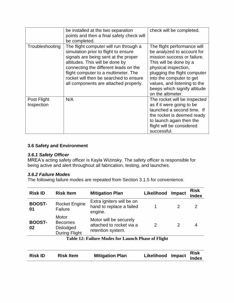
3.6.2 Failure Modes The following failure modes are repeated from Section 3.1.5 for convenience.
Risk ID Risk Item Mitigation Plan Likelihood Impact Risk Index
BOOST-01
Rocket Engine Failure
Extra igniters will be on hand to replace a failed engine.
1 2 2
BOOST-02
Motor Becomes Dislodged During Flight
Motor will be securely attached to rocket via a retention system.
2 2 4
Table 12: Failure Modes for Launch Phase of Flight
Risk ID Risk Item Mitigation Plan Likelihood Impact Risk Index

CONTROL-03
Control System Deployment Failure
The flaps will be aligned in the upright position on the pad so that they will act as fins if computer fails.
3 3 9
CONTROL-04
Microcontroller in-flight failure
Extensive testing of the flight computer system will be performed, including static tests, wind tunnel tests, and flight tests.
3 4 12
CONTROL-05
Actuator Servos or Gearbox Jams
The servo system and gearbox will be verified extensively before launch under static loads, wind tunnel tests, and test flights.
2 3 6
CONTROL-06
Only a Single Flap Deploys
A correction mechanism will be programmed into the control algorithm to return single flap to the upright position if detected. Extensive testing on controls will also be performed.
2 5 10
CONTROL-07
Vehicle becomes Unstable During Flight
Verification of stability will be performed through CFD analysis, wind tunnel tests, and test launches.
2 5 10
Table 13: Failure Modes for Controls Subsystem
Risk ID Risk Item Mitigation Plan Likelihood Impact Risk Index
OPS-13
Vehicle Damaged During Transport
The vehicle will be transported in a separate compartment to ensure it will not be damaged by spare parts.
1 5 5

OPS-14 Ejection Charges Ignite Before Launch
Ejection charges will not be armed and igniters will not be installed until vehicle is on launch pad to prevent a premature launch. A switch on the exterior of the rocket will arm the flight computers after the rocket is on the pad.
1 4 4
OPS-15
Spectator is Harmed by Launch Vehicle
Announcements will be made to warn spectators that a vehicle is being launched and spectators will be positioned a safe distance from the launch pad.
1 5 5
Table 14: Failure Modes for Launch Operations
Risk ID Risk Item Mitigation Plan Likelihood Impact Risk Index
RECOV-26
Electric Match Failure
There are redundant pyro-charges for the main parachute.
2 5 10
RECOV-27
Recovery System Flight Computer Failure
Testing of the flight computer.
2 4 8
RECOV-28
Electric Match Failure
There are redundant pyro-charges for the main parachute.
2 5 10
RECOV-29
Pressure Senor Inaccuracy
There are redundant sensors on the flight computer.
2 5 10
RECOV-30
Recovery Location System Failure
The GPS-based recovery system will be tested.
3 2 6
RECOV-31
Delayed Time Charge Failure
There are redundant charges and two electric matches.
3 5 15
RECOV-32
Wire Disconnect
All wiring in the rocket will be carefully placed and staked.
1 4 4

RECOV-33
Shock Chord Fails to Hold Parachute Together
A ½-inch thick cord fastened securely to the rocket and parachute will be used. Safe charge amounts will be calculated and tested.
1 3 3
Table 15: Failure Modes for Recovery Subsystem
Risk ID Risk Item Mitigation Plan Likelihood Impact Risk Index
STRUCT-34
Parachute Damage or “Stuck” in Airframe
Careful review of the parachute packing and rocket sizing.
1 3 3
STRUCT-35
Bond between Valve Tubes and Airframe Fails
Structural integrity will be verified through FEA and static load testing.
2 4 8
STRUCT-36
Rocket Explodes during launch
The rocket body is constructed with a high-strength polymer frame (blue tube). Test launches and static load tests will verify structural integrity.
1 5 5
STRUCT-37
Fins Separate During Launch
Fins will be attached to the engine mount by going through the body of the rocket. The fins will be attached at two points with fillets on the body tube.
1 3 3
Table 16: Failure Modes for Structural Integrity of Launch Vehicle
3.6.3 Personnel Hazards Multiple procedures and protocols are in place to ensure a safe working environment. The work space is kept in a clean condition to prevent injuries and increase productivity. All potentially hazardous materials are securely kept with their MSDS in an easily locatable binder that is shared by all student groups in the workspace. All students must attend safety lectures where injury and accident prevention is discussed in-depth and to use any machining tools the student must have Wilson Center Training. In addition lab supervisors are present to enforce the rules and protocols.

Risk ID Risk Item Mitigation Plan Likelihood Impact Risk Index
PERS-16
Epoxy toxic fumes, skin irritation, eye irritation
Team members will work in well-ventilated areas, wear face masks, gloves, and goggles at all times during construction.
2 3 6
PERS-17
APCP Rocket Propellant skin irritation, inadvertent ignition, burns to skin
Gloves will be worn at all times to prevent skin irritation. Propellant will be kept away from ignition sources, such as matches, igniters, heat sources, and stored in proper Type 3 or Type 4 magazines to prevent inadvertent ignition. After motor burn, the team will wait 15 minutes before disassembling the motor, while wearing insulated gloves to prevent burns to skin.
1 5 5
PERS-18
Cuts and lacerations, burns to skin, eye irritation due to operation of machinery
Wilson Center training is required before using machinery so that proper instruction is taught to everyone. Goggles will be worn at all times to prevent eye irritation. The Wilson Center has more rules that will be followed as well.
2 4 8
PERS-19
Ejection Charge Test skin irritation, eye irritation, inadvertent ignition, burns to skin
Personnel involved will remain a safe distance away from ejection charges and the test will be done in an open area.
1 5 5

PERS-20
Vehicle Test flying debris, eye irritation, inadvertent ignition, burns to skin
All NAR regulations will be obeyed to provide safety for anyone involved.
2 5 10
Table 17: Failure Modes for Personnel Hazards
3.6.4 Environmental Concerns
Risk ID Risk Item Mitigation Plan Likelihood Impact Risk Index
ENVIRON-08
Extreme Windy Conditions, Heavy Rain, or Snow
Launch will be scrubbed and rescheduled.
3 3 9
ENVIRON-09
High Winds
Parachute deployment altitude will be lowered to decrease drift distance. In the case of test launch, smaller motor may be used to reduce overall altitude.
4 2 8
ENVIRON-10
Mild Rain
The rockets exterior, to avoid wetting of the ignition strips, covers the ignition system. The exterior structure of the rocket is durable enough to withstand light rain.
3 1 3
ENVIRON-11
Cloudy Day
GPS recovery system will help locate rocket. Launch may be delayed or a smaller motor may be chosen to reduce chance of loss of launch vehicle.
3 1 3
ENVIRON-12
Mild Wind
The angular orientation of the rocket will be adjusted according to launch day wind conditions.
5 1 5
Table 18: Failure Modes for Environmental Concerns

4. Payload Criteria
4.1 Selection, Design, and Verification of Experiment
4.1.1 Review of Experiment Most of the selection, design, and verification of the experiment were covered in Section 3 concerning the vehicle due to our lack of a payload. This section will describe alternative methods that were considered and rationale for the butterfly valve. The drag-control device consists of two cans (tubes mounted on opposite sides of the rocket body) with a butterfly valve. Each can is mounted at the base of the rocket and runs 35 inches towards the nose of the rocket. The tubes will contain one flap each which will be located 8 inches aft of the can inlet. The butterfly valve was chosen due to the availability of rotational servos and the speed at which we could actuate from full to zero drag. This drag system is a challenging application of a 1-D control algorithm, which is the first step towards a control system for a cruise missile, or even the shuttle. This is an interesting problem due to its primarily engineering nature, and direct application to control of 1-D vehicles (such as trains or cruise control in cars)
4.1.2 Aerodynamic Analysis – Butterfly Valves We conducted analysis in ANSYS Fluent CFD to predict the aerodynamic forces acting on the drag flap. This study will be used to get a diameter required to adequately slow the rocket to a mile in altitude. As a preliminary study, an incompressible analysis was conducted with laminar flow in order to predict drag to a first order. The analysis was conducted on a rocket half-body with tubes of varying thickness and diameter, as well as varying gaps between the butterfly valve and the inner diameter of the cans.
4.1.3 Mesh Type and Sizing The mesh was created in ANSYS Fluent CFD with the mesh automatic sizing option which generates a patch conforming/sweeping mesh. The mesh was further refined in areas of interest such as the drag flap as well as the interior wall of the can, this can be seen in Figure 12. The inlet conditions were set to a velocity magnitude of 300 m/s (984 ft/s) to simulate the drag at a speed similar to that of the maximum flight speed of our rocket achieved from our flight profile. The gauge pressure was set to zero Pascal‟s to make the data analysis process more efficient.
Figure 9: Close view of relative mesh sizes

Figure 10: Pressure Contours on Butterfly Valve

Calibration Functions:
4.1.4 Moment Concerns A primary concern of this design was the possibility of the butterfly valves to create a moment along the butterfly valve‟s axis. (x-axis in figures above) Figure 14 shows that there is a high force in the y direction, however this force is negated by the pressures which act along the inside wall of the can. In order to prove that this drag system will not flip our rocket, the moment was analyzed at the most extreme case. This corresponded with the largest can size (Ø2.551 inner) and the largest flap corresponding to that can (Ø2.451) at 45° which is shown in Figure 10. The moment-causing force was as shown below.
Component Force in y-direction [N]
Rocket -199.8 Flap 199.6
This shows that the force in the y-direction caused by the flap angle deflection is negated by the force it creates on the interior wall of the can. Note: All data is from a simulated wind speed of 300 m/s Can inner diameter: 1.504 in Can outer diameter: 1.616 in
0
50
100
150
200
250
0 10 20 30 40 50 60 70 80 90
Forc
e O
n F
lap (
N)
Flap Angle α from Free-Stresm (deg)
Mag(Fy)
Mag(Fz)
Poly. (Mag(Fy))
Power (Mag(Fz))
Figure 11: Drag Characterization of Ø2.035" Flap
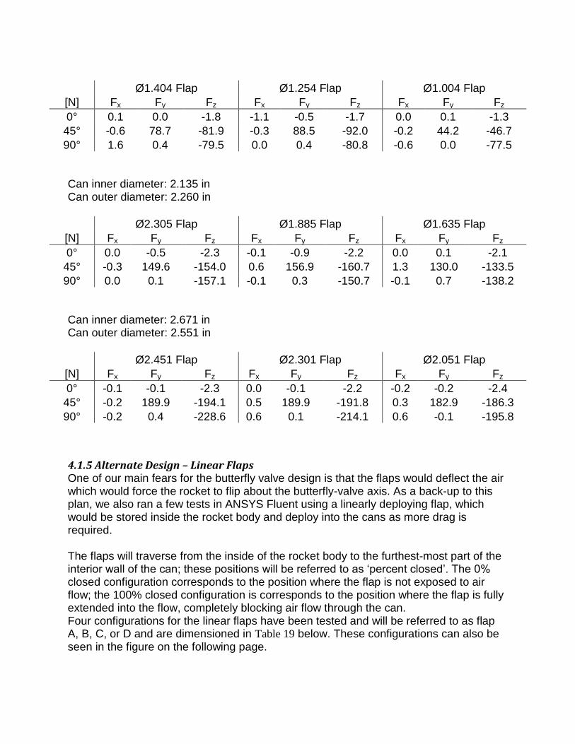
Ø1.404 Flap Ø1.254 Flap Ø1.004 Flap
[N] Fx Fy Fz Fx Fy Fz Fx Fy Fz
0° 0.1 0.0 -1.8 -1.1 -0.5 -1.7 0.0 0.1 -1.3
45° -0.6 78.7 -81.9 -0.3 88.5 -92.0 -0.2 44.2 -46.7
90° 1.6 0.4 -79.5 0.0 0.4 -80.8 -0.6 0.0 -77.5
Can inner diameter: 2.135 in Can outer diameter: 2.260 in
Ø2.305 Flap Ø1.885 Flap Ø1.635 Flap
[N] Fx Fy Fz Fx Fy Fz Fx Fy Fz
0° 0.0 -0.5 -2.3 -0.1 -0.9 -2.2 0.0 0.1 -2.1
45° -0.3 149.6 -154.0 0.6 156.9 -160.7 1.3 130.0 -133.5
90° 0.0 0.1 -157.1 -0.1 0.3 -150.7 -0.1 0.7 -138.2
Can inner diameter: 2.671 in Can outer diameter: 2.551 in
Ø2.451 Flap Ø2.301 Flap Ø2.051 Flap
[N] Fx Fy Fz Fx Fy Fz Fx Fy Fz
0° -0.1 -0.1 -2.3 0.0 -0.1 -2.2 -0.2 -0.2 -2.4
45° -0.2 189.9 -194.1 0.5 189.9 -191.8 0.3 182.9 -186.3
90° -0.2 0.4 -228.6 0.6 0.1 -214.1 0.6 -0.1 -195.8
4.1.5 Alternate Design – Linear Flaps One of our main fears for the butterfly valve design is that the flaps would deflect the air which would force the rocket to flip about the butterfly-valve axis. As a back-up to this plan, we also ran a few tests in ANSYS Fluent using a linearly deploying flap, which would be stored inside the rocket body and deploy into the cans as more drag is required. The flaps will traverse from the inside of the rocket body to the furthest-most part of the interior wall of the can; these positions will be referred to as „percent closed‟. The 0% closed configuration corresponds to the position where the flap is not exposed to air flow; the 100% closed configuration is corresponds to the position where the flap is fully extended into the flow, completely blocking air flow through the can. Four configurations for the linear flaps have been tested and will be referred to as flap A, B, C, or D and are dimensioned in Table 19 below. These configurations can also be seen in the figure on the following page.

Flap Max % Closed Flap End Geometry
Can Inner Dia [in] Flap Width [in]
A 100 Semi-Circle 1.504 1.504 B 100 Semi-Circle 2.551 2.551 C 65 Rectangular 2.551 2.551 D 75 Rectangular 2.551 2.051
Table 19: Flap Geometry
Table 20 shows the maximum drag corresponding to each flap during the simulated run cases at 300 m/s. Full drag profiles are available in the proceeding pages of this section. All flap data is for one flap and all rocket data is for a rocket half-body
Flap Maximum Drag [N]
A 81.7235
B 240.396
C 204.086
D 197.838
Table 20: Flap Max Drag
Flap A Flap B
Flap C
Flap D

4.2 Concept Features and Definition We believe that this experiment is creative because it would allow us to avoid experimental error
from purchased parts such as rocket motors. Since rocket motors have a range of impulse that
come with the same motor, we can eliminate this by varying the drag on our rocket. Rather than
picking a motor that gets the rocket to one mile at apogee in perfect conditions, we can choose
any motor that will take our rocket over one mile at apogee. Therefore, we avoid errors from the
tolerances on rocket motors, poor launch conditions, and strange flight patterns.
0
50
100
150
200
250
0 10 20 30 40 50 60 70 80 90 100
Dra
g [
N]
Percent Closed [%]
Calculated Drag on FlapFlap A
Flap B
Flap C
Flap D

This experiment will be a challenge because extensive testing of the program for actuating drag
must be done, and this will involve a lot of debugging to ensure the proper transmittal of data.
This project is also difficult from a structures standpoint because we have to come up with a
method for actuating the valves that can handle large moments created by drag on the flaps.
Finally, this project is challenging because it involves a great deal of CAD, CFD, and wind
tunnel testing. We need to build CAD models, then import them to CFD to see if the results are
realistic, and then build the rocket and test it in a wind tunnel to get the values for the drag
coefficient at different valve angles.
4.3 Science Value
4.3.1 Experimental Objectives Our payload will employ a Proportional Integral Derivative (PID) controller which will govern the aforementioned mechanism designed to induce pressure drag as a means of regulating vehicle altitude. The control system will be actuated at a pre-designated trigger velocity to ensure that our flight speed has passed the highly unstable transonic regime, where shock formation on our control surfaces could lead to instabilities. The most significant objective of our controller is induction of pressure drag in the mean energy solution path such that both apogee-amplifying and apogee-depreciating perturbations are recoverable. The controller should be robust enough to recover altitude goals over various launch environment conditions expected during operation in testing and in competition. Drag should be calculated dynamically during flight, and the controller should respond to physical system changes in no more than 50 milliseconds.
4.3.2 Experiment Success Criteria Of utmost importance in payload success is that drag is actuated exclusively opposite to the vehicle velocity vector, and that no moments are created around any other axis than the longitudinal body axis of our vehicle. The control system must demonstrate sufficient disturbance rejection over the range reasonable environmental perturbations encountered during flight at any stage, and recover within 20 feet of the goal altitude. In order to recognize payload mission goals, a discrete time control system model was developed, and refined through design iteration until measureable outcomes were consistently and successfully simulated with high system fidelity. Below is a figure of the system model as designed in Simulink, with a brief overview as to each mechanisms purpose in achieving mission goals. A more robust discussion of each mechanism can also be found below.
4.3.3 Method of Investigation and Test Variables

Dynamic Target: Used to aid in assuring the mean energy path solution is followed Restrained Controller: Proportional Integral Derivative (PID) derived controller with physical limits Physics Plant: Simulation of vehicle-environment interaction given controller commands Instrument Uncertainty: Propagation of instrument uncertainty into system values Alt. Projection: Projection of rocket apogee altitude with same physics plant model for consistency Variables Referred to in Discussion of DART Controller Altitude above Ground Level (AGL)------------------------------------ --------------------------
AGL altitude when control system is activated----------------------------------------------------
Target apogee altitude (1 mile)------------------------------------------------ ----------------------
Command altitude-------------------------------------------------------------------------------------
Altitude above Sea Level (ASL)------------------------------------------- ------------------------
Velocity with respect to altitude---------------------------------------------------------------------- Velocity with respect to altitude when control system is activated------------------------------ Acceleration with respect to altitude----------------------------------------------------------------- Butterfly valve angle of attack (0 corresponds to natural, i.e. min drag, configuration)-----
Angle of attack-----------------------------------------------------------------------------------------
Reynolds number with respect to natural diameter-----------------------------------------------
Total vehicle mass-------------------------------------------------------------------------------------
Acceleration of gravity--------------------------------------------------------------------------------
Natural configuration coefficient of drag------------------------------------------------------------
Natural configuration cross-sectional area seen by incoming fluid (air)-- ---------------------
Induced coefficient of drag---------------------------------------------------------------------------- Induced drag configuration cross-sectional area seen by incoming fluid (air)----------------- Density of fluid (air) using the 1976 standard atmosphere model--------------------------------
Temperature at Sea Level------------------------------------------------------------------------------
Pressure at Sea Level-----------------------------------------------------------------------------------
Gas Constant of Air-------------------------------------------------------------------------------------
Temperature Lapse Rate (1976 U.S. Standard Atmosphere) -------------------------------------

Dynamic Target
The dynamic target block is used as part of the system which assures that the controller targets the best energy path solution to achieve one mile altitude while retaining the ability to reject disturbances. In this system it is particularly relevant to realize that our vehicle has depreciating control ability as apogee is approached. This is due to the fact that our control is pressure drag based, meaning that as we lose velocity, we lose the ability to actuate as much pressure drag. To compensate for this effect , we introduce a target based off of the following formula:

This nontrivial part of this equation represents a sine wave target that oscillates about a one mile command with the magnitude of oscillation decreasing as the ratio of velocity squared to initial velocity squared. The command is based off a single period of oscillation starting off with an undershoot command during early high-velocity flight due to our vehicle having the most energy to drag at that point. This behavior tends to keep our vehicle near the mean energy path solution, allowing robust disturbance rejection when coupled with a well-tuned PID controller.
Restrained Controller
The restrained controller is used to implement modified PID control while respecting the physical limitations of our system and our environment. The PID controller itself is a

typical implementation as seen below using the forward Euler method in our discrete time domain. PID Sub-Block
The command from the PID controller is fed directly into the dynamic saturation block to ensure that the controller is not attempting to actuate drag that the vehicle cannot physically perform. The lower limit for this saturation block is the effective nominal drag of our vehicle and remains constant throughout our flight. The upper limit for this saturation block is the maximum drag our system can induce at any given velocity. This command is then fed into the derivative constraint block. d/dt Sub-Block
This feedback driven block assures that the difference between our last command and our current command is not more than our system can actuate. If the difference is too large, it commands the largest possible value it can in the functional direction in which the system was attempting to actuate. This block assures that our controller does not damage system components, or give commands that the controller does not have enough time to perform. This command is then fed into the perturbation block. Instrument Perturbations Sub-Block

To more accurately model a real physical system, Gaussian white noise is introduced
into the drag command at a magnitude of of the commanded value. This uncertainty not only accounts for inaccuracies in realizing commanded values of drag, but also accounts for aerodynamic flutter possibly present in early phases of our flight. The adjusted drag command output is then considered against one final check. If the system detects that the vehicle is falling apogee separation is assumed to have occurred and drag is modified to represent that for simulation purposes. Physics Plant
The physics plant is responsible for simulating our flight path given an effect drag coefficient, and initial conditions. Our physical model is built as follows: Physical Model Assumptions:
-
-
-
-
-
-
Governing Equation of Motion

Here we recover a second-order nonlinear ordinary differential equation that governs the physics of our rockets altitude. This differential is evaluated numerically, and comprises the physics of our simulation model. Density is evaluated using the following sub-block, based on the 1976 U.S. Standard Atmosphere model: Standard Atmosphere (1976) Model Sub-Block
The above block is based on the following formula where altitude, , is measured in meters above sea level.
Further iteration may include gravity turning effects and some relaxation of the small angle of attack assumption to develop a more robust system model. Which assumptions to relax will be a product of field testing.

4.3.4 Relevance of Expected Data and Progress
To more accurately model our system, uncertainty in measurements and how those propagate throughout the system must be considered. In this block, we consider Gaussian white noise on the uncertainty level of our altimeter. This uncertainty is amplified at high velocity, due to the dynamics of our system resulting in a large change in altitude between every requested altitude value. However, as our vehicle slows down and we receive more altitude measurements with respect to our velocity, we can be more certain that the instrument is behaving as we would expect. This is subject to change based on where our velocity and acceleration data comes from. Costs and benefits of employing numeric derivation vs. numeric integration are being considered to determine if accelerometer or altimeter data will be used to determine velocity and acceleration. Apogee Calculation
As our vehicle ascends, we need to have a method to dynamically calculate our drag, and project apogee based on that calculation. The following block uses only information that will be available to our controller, and calculates expected vehicle response. Also, it is important for simulation purposes that we are consistent in our altitude projection model and our physics model. If there are discontinuities between these two models, our projected apogee and our attained apogee coinciding would be nothing more than

coincidence. Hence, all of the assumptions invoked in the description of our flight physics above are valid for the following discussion. First, we will consider the subsystem that calculates our effective coefficient of drag. Induced Drag Coefficient to Effective Drag Coefficient Sub-Block
Revising our physics plant, we will use our governing equation of motion (repeated here for convenience) to help describe this mapping of physical properties to effective drag coefficient.
Since we are now interested in an analytic answer to the differential equation governing vehicle altitude that can be executed with reasonable computational effort, we will reduce the second order differential‟s complexity by letting density be constant. Specifically we quantify average density as the mean density between one mile altitude and our current position. This allows us to express our physics equations as
Altitude Projection Sub-Block
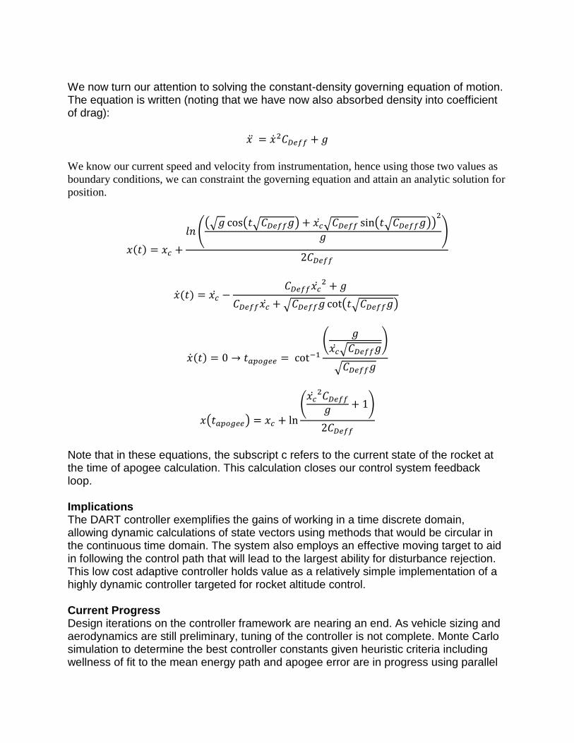
We now turn our attention to solving the constant-density governing equation of motion. The equation is written (noting that we have now also absorbed density into coefficient of drag):
We know our current speed and velocity from instrumentation, hence using those two values as
boundary conditions, we can constraint the governing equation and attain an analytic solution for
position.
Note that in these equations, the subscript c refers to the current state of the rocket at the time of apogee calculation. This calculation closes our control system feedback loop. Implications The DART controller exemplifies the gains of working in a time discrete domain, allowing dynamic calculations of state vectors using methods that would be circular in the continuous time domain. The system also employs an effective moving target to aid in following the control path that will lead to the largest ability for disturbance rejection. This low cost adaptive controller holds value as a relatively simple implementation of a highly dynamic controller targeted for rocket altitude control. Current Progress Design iterations on the controller framework are nearing an end. As vehicle sizing and aerodynamics are still preliminary, tuning of the controller is not complete. Monte Carlo simulation to determine the best controller constants given heuristic criteria including wellness of fit to the mean energy path and apogee error are in progress using parallel

computing techniques in Matlab. Currently implementation of the controller into executable C++ for hardware in the loop testing is also under progress so that hardware integration testing can begin.
4.4 Safety and Environment for Experiment MREA‟s acting safety officer is Kayla Wizinsky. As mentioned in Section 3.6 she is responsible for the safety involving the vehicle. Since we do not have a payload and are doing an experiment instead, Kayla is the officer. All hazards that could go wrong with the experiment are mentioned in Section 3.6 under the vehicle safety.
5. Activity Plan
5.1 Budget MREA‟s budget for the USLI project is outlined below in Table 21. Overall, the launch vehicle is expected to cost $2,850. These costs are based on preliminary estimates of major component prices, as well as knowledge of pricing from last year‟s competition. The category with the highest likelihood to change is the structural subsystem, as broken parts are possible in test flights and manufacturing. To account for this, the Structural Subsystem category has an extra miscellaneous costs built in, as well as extra money to buy body tubing that might not be needed. Finally, the travel expenses are based on last year‟s actual travel costs. MREA again plans to take 10-15 team members and this budget accounts for a similar number.
Expense Price
(USD) Quantity Total (USD)
"Blue" Phenolic Tubing 38.95 10 units 389.50 Nose Cone 20.95 1 unit 20.95 Pre-Cut Fins 11.00 3 units 33.00 Centering Rings 4.00 10 units 40.00 Bulkhead Plates 1.84 12 units 22.08 Launch Lugs 1.32 6 units 7.92 Rip-Stop Nylon Shock Chord 1.63 20 yards 32.60 Misc. Structures (Bolts, etc.) 100.00 1 unit 100.00
Structural System Expenses 646.05
Altimeter 99.95 1 unit 99.95 GPS Locator 200.00 1 unit 200.00 Avionics Structures Bay 150.00 1 unit 150.00 Arduino 100.00 1 unit 100.00 Misc. Electronics (Wires, etc.) 100.00 1 unit 100.00
Controls System Expenses 649.95
Motor Mount System 100.00 2 unit 200.00 Motor Casing Set 120.00 1 unit 120.00

Ematches 1.00 10 units 10.00 Test Launch Motors 5.00 100 unit 500.00
Propulsion System Expenses 830.00
Parachute 49.50 1 unit 49.50 Altimeter 99.50 1 unit 99.50 Flight Computer 155.00 1 unit 155.00 Recovery System Avionics Bay 150.00 1 unit 150.00
Recovery System Expenses 454.00
Shipping 200.00 N/A 200.00
Miscellaneous Expenses 200.00
Car Rental 250.00 2 units 500.00 Gas 0.15 1950 miles 292.50 Hotel 280.00 5 nights 1,400.00
Travel Expenses 2,192.50
TOTAL 4,972.50
Table 21: Expected Expenses for USLI
MREA currently has $5,456.67 in guaranteed funding, which is more than enough to fund the USLI project at this time. These funding sources are detailed in Table 22, and include funding from the Aerospace Engineering Department, as well as an outside corporation. In the event that MREA needs additional funding, we can approach the student government organizations (Michigan Student Assembly and University of Michigan Engineering Council). Both of these groups accept funding applications on a rolling basis and were accommodating to MREA during last year‟s USLI.
Income Amount
Starting Balance $1,956.67 Aerospace Dept. Grant
$2,500.00
Raytheon Grant $1,000.00
TOTAL $5,456.67
Table 22: Guaranteed Income Sources for USLI Project
5.2 Schedule and Timeline The timeline below is the schedule that MREA has been using to meet all project goals. September 2011 26 Proposal Due
October 2011
1 – Nov. 4 Website Creation and Development 1 – 21 Preliminary Design Verification 17 Selection notification 21 Teleconference 1 – 31 Preliminary CFD, CAD, and Simulink Analysis

November 2011 1 – 20 Compilation and Integration of Preliminary Analysis
1 – 27 Preliminary Design Review (PDR) development 4 Website Completed 28 PDR Completed
December 2011
5 – 14 PDR Presentation 1 – 15 Preparation and Development of Ground Tests 15 – 22 Order and Acquisition of Parts 14 – Jan. 4 Final Exams and Winter Break January 2012
4 – 22 Critical Design Review Development 4 – 15 Preliminary Subsystem Construction and Ground Tests 23 CDR Completed 23 – Feb. 10 Construction and Preliminary Integration
February 2012
1 – 10 CDR Presentation 1 – 15 Systems Ground Tests
16 – 29 Construction of Final Vehicle Subsystems March 2012
1 – 15 Final Vehicle Assembly and Integration 1 – 26 Flight Readiness Review Development 26 FRR Completed
TBD Test Flight of Final Vehicle April 2012
2 – 11 FRR Presentation 18 Travel to Huntsville 19 – 20 Flight Hardware and Safety Check 21 Launch Day 22 Travel Home
23 – 30 Final Exams May 2011:
1 – 6 Post-Launch Assessment Review Development 1 – 6 Launch Evaluation and Data Analysis 7 PLAR Completed 18 Announcement of USLI Competition Results

The Gantt chart in Figure 12 below visualizes the remaining tasks that MREA has left for the USLI project.
Figure 12: Gantt Chart of Remaining Tasks
11/14 1/3 2/22 4/12 6/1
Development of Ground Tests
Parts Acquisition
Final Exams and Winter Break
CDR Development
Subsystems Construction & Testing
CDR Completed
Preliminary System Integration
CDR Presentation
Systems Ground Tests
Final Subsystems Construction
Final Assembly & Integration
FRR Development
FRR Completed
Test Flight
FRR Presentation
Travel to Huntsville
Flight Hardware & Safety Check
Launch Day
Travel Home
Final Exams
PLAR Development
Launch Data Evaluation
PLAR Completed
Announcement of USLI Results

5.3 Educational Engagement MREA plans to develop a few outreach events aimed at upper elementary level students. MREA is working with local schools to set up events in a small classroom setting, working with students in grades four, five, and six. MREA will provide students with an introduction to the field of rocketry as well as a presentation of the proposed rocket for competition and a hands-on activity that will be exciting and spark an interest in rocketry. MREA will instruct students on how to make water pressure bottle rockets where they are free to design their own fins that they will attach to their “rocket”. We will use two liter pop bottles for the body of the rocket and card stock paper for the fins. Each rocket will be filled with water and launched outside using bike pumps with adapters to create pressure in the body of the rocket, propelling it off the ground. MREA plans to hold a competition of how high each rocket can go. Students can choose the amount of water they fill their rocket with, which will create different pressures and therefore different heights. MREA plans to make these events as informative and fun as possible for this level of education.
6. Conclusion Project Wolverine is 85 in long, has an outer diameter of 5.58 in, and will weigh right around 20
pounds. It will consist of 4 fins, and two of these fins will be attached to butterfly valves which
can vary the pressure drag on the rocket. The end result is an experiment that will meet the
following criteria.
1. The butterfly valves must stay in their neutral configuration, parallel to the longitudinal axis of the rocket, at launch and throughout engine burn.
2. The control system must iteratively take readings from the altimeter after engine burnout and determine the correct orientation of the butterfly valves.
3. The rocket must reach 5280 ± 100 feet in altitude. 4. The rocket must separate at apogee. 5. The rocket must deploy its main parachute at 500 feet. 6. All sections of the rocket must be intact and functional upon recovery. 7. Data describing the positions of the butterfly valves during flight must be
recovered and analyzed to fine tune the control algorithm.