Embed Size (px)
Citation preview
UNIVERSITI PUTRA MALAYSIA
COMPACT BANDPASS FILTERS USING DUAL-MODE MICROSTRIP CLOSED-LOOP RING RESONATORS FOR WIRELESS
COMMUNICATION SYSTEMS
BABAK KAZEMI ESFEH
FK 2009 79

COMPACT BANDPASS FILTERS USING DUAL-MODE MICROSTRIP CLOSED-LOOP RING RESONATORS FOR WIRELESS
COMMUNICATION SYSTEMS
By
BABAK KAZEMI ESFEH
Thesis Submitted to the School of Graduate Studies, Universiti Putra Malaysia, in Fulfilment of the Requirement for the Degree of Master of Science
August 2009

ii
DEDICATION
TO
MY BELOVED PARENTS

iii
ABSTRACT
Abstract of thesis presented to the Senate of University Putra Malaysia in fulfilment of the requirement for the degree of Master of Science
COMPACT BANDPASS FILTERS USING DUAL-MODE MICROSTRIP CLOSED-LOOP RING RESONATORS FOR WIRELESS
COMMUNICATION SYSTEMS
By
BABAK KAZEMI ESFEH
August 2009
Chairman: Alyani Ismail, PhD
Faculty: Engineering Microwave filters have important role in many wireless and communication systems
such as satellite and cellular mobile organizations. In such kind of systems, factors
such as compact size, low cost, light weight, high performance, and low loss in
designing of microwave filters are of primary importance. In comparison with
waveguide filters, microstrip filters are smaller and in such applications mentioned
before there are needs to have smaller microstrip filters.
In this thesis, filters using dual-mode ring resonators is proposed, because they can
be designed easier than the other kind of microwave filters and are more compact. In
this thesis, a new compact form of dual-mode microstrip octagonal loop resonator
filter is proposed in two forms; conventional and compact. These structures are
designed to operate at WiMax frequency of 2.3 GHz with a 5% fractional bandwidth.
The new dual-mode resonator will be produced by adding a rectangular patch inside
the loop resonator. The experimental results and simulated values are presented and
show good agreement.
iv
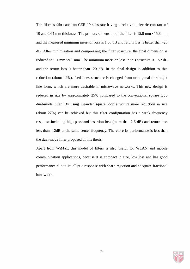
The filter is fabricated on CER-10 substrate having a relative dielectric constant of
10 and 0.64 mm thickness. The primary dimension of the filter is 15.8 mm×15.8 mm
and the measured minimum insertion loss is 1.68 dB and return loss is better than -20
dB. After minimization and compressing the filter structure, the final dimension is
reduced to 9.1 mm×9.1 mm. The minimum insertion loss in this structure is 1.52 dB
and the return loss is better than -20 dB. In the final design in addition to size
reduction (about 42%), feed lines structure is changed from orthogonal to straight
line form, which are more desirable in microwave networks. This new design is
reduced in size by approximately 25% compared to the conventional square loop
dual-mode filter. By using meander square loop structure more reduction in size
(about 27%) can be achieved but this filter configuration has a weak frequency
response including high passband insertion loss (more than 2.6 dB) and return loss
less than -12dB at the same center frequency. Therefore its performance is less than
the dual-mode filter proposed in this thesis.
Apart from WiMax, this model of filters is also useful for WLAN and mobile
communication applications, because it is compact in size, low loss and has good
performance due to its elliptic response with sharp rejection and adequate fractional
bandwidth.

v
ABSTRAK
Abstrak tesis yang dikemukakan kepada Senat Universiti Putra Malaysia sebagai memenuhi keperluan untuk ijazah Master of Sains
PENURAS LULUS JALUR KOMPAK MENGGUNAKAN PENYALUN MIKROSTRIP GELUNG PUSINGAN TERTUTUP DUA MOD UNTUK
SISTEM KOMUNIKASI TANPA WAYAR
Oleh
BABAK KAZEMI ESFEH
Ogos 2009
Pengerusi: Alyani Ismail, PhD
Fakulti: Kejuruteraan
Penapis mikrogelombang mempunyai banyak peranan dalam sistem wayarles dan
sistem komunikasi seperti satelit dan sistem telefon mudah alih. Dalam sistem
tersebut, faktor dalam sesuatu rekaan penapis mikrogelombang adalah sangat penting
dan perlu diambilkira. Saiz yang bersesuaian, harga yang berpatutan, ringan, kualiti
yang tinggi, dan hingar yang rendah adalah antara faktor yang diperlukan untuk
meningkatkan mutu produk dan mengurangkan kos perlaksanaannya. Saiz penapis
mikrogelombang adalah lebih kecil berbanding penapis waveguide. Tetapi, untuk
aplikasi tersebut, penggunaan penapis mikrogelombang yang bersaiz kecil sangat
bersesuaian. Terdapat banyak permintaan terhadap penapis yang menggunakan
penyalun gelang dua mod. Rekaannya adalah lebih ringkas berbanding penapis
mikrogelombang yang lain. Dalam tesis ini, satu bentuk penapis dual mode
mikrostrip penyalun gelung berbentuk oktagon yang padat dicadangkan dalam dua
bentuk iaitu; piawai biasa dan kompak. Struktur ini direka untuk beroperasi pada
frekuensi 2.3 GHz sebagai frekuensi WiMax dengan 5% pecahan lebar jalur.

vi
Penyalun dua mod akan dihasilkan dengan menambahkan bahagian berbentuk segi
empat tepat di dalam gelung penyalun. Penapis ini telah direka , CER-10
menggunakan substrat yang mempunyai pekali dielektric 10 dan ketebalan 0.64 mm.
Struktur asal penapis ialah 15.8 mm x 15.8 mm dan nilai kehilangan sisipan ialah
1.68 dB dan nilai kehilangan pulangan ialah 20 dB. Selepas proses pemadatan dan
pengurangan struktur penapis, dimensi penapis dikurangkan kepada 9.1mm x 9.1
mm. Jumlah minimum kehilangan sisipan dalam struktur ini adalah 2.6dB dan
kehilangan pulangan lebih tinggi dari 22 dB. Dalam rekabentuk pengurangan saiz di
peringkat akhir (dalam 42%), struktur garis masukan ditukar dari bentuk paksi yang
bersudut tepat ke bentuk garis lurus, yang lebih diperlukan dalam rangkaian
mikrogelombang. Rekabentuk ini juga dibandingkan dengan bentuk penapis piawai
biasa gelung segiempat dua mod yang mempunyai pengurangan saiz sebanyak 25%.
Dengan menggunakan struktur segiempat gegelung kekelokan , pengurangan saiz
(dalam 27%) boleh dicapai. Tetapi penapis jenis ini mempunyai kelemahan dari segi
sambutan frekuensi termasuklah kehilangan sisipan jalur lalu yang tinggi (lebih
daripada 2.6 dB) dan return loss kurang daripada -12dB di frekuensi tengah yang
sama. Oleh yang demikian, persembahannya adalah kurang memuaskan daripada
penapis dual mode yang dicadangkan dalam tesis ini.
Model penapis ini sangat berguna untuk aplikasi WLAN dan sistem komunikasi,
kerana saiz yang padat, kehilangan yang rendah, mempunyai keputusan yang baik
dalam menapis dan pecahan lebar jalur yang memadai. Keputusan eksperimen dan
simulasi yang dicadangkan telah menunjukkan mutu persembahan yang baik.

vii
ACKNOWLEDGEMENT
Firstly, I wish to thank GOD, the merciful and kind for all the blessing upon me.
My deepest gratitude and appreciation goes to my supervisor, Dr. Alyani Ismail for
all her valuable comments, suggestions, patience and encouragement in my study and
the preparation of this thesis. Her professional review helped me to improve this
thesis more.
Also, I would like to thank Dr. Raja Syamsul Azmir b. Raja Abdullah, my co
supervisor for his constructive suggestions and helps.
My warmest gratitude goes to my family members especially my mother for her
continuous support and encouragement and my father for being my strongest
supporter.
Special thanks to my best friend Dr. Vahid Soluk for supporting me in my study
from the start of my project until finalizing this thesis.
Finally, I wish to thank to all my friends especially, Adam, Helmi, Aris and Ayub for
their help and support.

viii
APROVAL
I certify that a Thesis Examination Committee has met on (August 7, 2009) to conduct the final examination of (Babak Kazemi Esfeh) on his thesis entitled "Compact Bandpass Filters Using Dual-Mode Microstrip Closed-Loop Ring Resonators for Wireless Communication Systems" in accordance with the Universities and University Colleges Act 1971 and the Constitution of the Universiti Putra Malaysia [P.U. (A) 106] 15 March 1998. The Committee recommends that the student be awarded the (Master of Science degree). Members of the Thesis Examination Committee were as follows:
Dr. Sabira Khatun, PhD Associate Professor Faculty of Engineering Universiti Putra Malaysia (Chairman) Dr. Roslina Mohd Sidek, PhD Associate Professor Faculty of Engineering Universiti Putra Malaysia (Internal Examiner)
Dr. Nor Kamariah Noordin, PhD Associate Professor Faculty of Engineering Universiti Putra Malaysia (Internal Examiner)
Dr. Mohd Fadzil Ain, PhD Engineering Campus Universiti Sains Malaysia Malaysia (External Examiner)
Bujang Bin Kim Huat, PhD Professor and Deputy Dean School of Graduate Studies Universiti Putra Malaysia
Date:

ix
This thesis submitted to the Senate of Universiti Putra Malaysia and has been accepted as fulfillment of the requirement for the degree of Master of Science. The members of the Supervisory Committee are as follows:
Alyani Ismail, PhD Lecturer Faculty of Engineering Universiti Putra Malaysia (Chairman) Raja Syamsul Azmir Raja Abdullah, PhD Lecturer Faculty of Engineering Universiti Putra Malaysia (Member)
HASANAH MOHD GHAZALI, PhD Professor and Dean School Of Graduate Studies Universiti Putra Malaysia Date: 16 October 2009

x
DECLARATION
I hereby declare that the thesis is based on my original work except for quotations and citations which have been duly acknowledged. I also declare that it has not been previously or concurrently submitted for any other degree at UPM or other institutions.
BABAK KAZEMI ESFEH Date:

xi
TABLE OF CONTENTS
DEDICATION ii ABSTRACT iii ABSTRAK v AKNOWLEDGMENT vii APROVAL viii DECLARATION x LIST OF TABLES xiii LIST OF FIGURES xiv LIST OF ABBREVIATIONS AND SYMBOL xvii LIST OF SYMBOLS xviii
1 INTRODUCTION 1 1.1 Background 1 1.2 Problem Statement and Motivation 2 1.3 Research Aim and Objectives 5 1.4 Thesis Scope 5 1.5 Scope of Research 6 1.6 Thesis Organization 8
2 REVIEW AND ANALYSIS OF MICROSTRIP DUAL-MODE FILTERS 10
2.1 Background 10 2.2 Microstrip Lines 12
2.2.1 Characteristic Impedance and Effective Dielectric Constant 14
2.2.2 Guided Wavelength, Phase Velocity, Electric Length and
Propagation Constant 15
2.2.3 Microstrip Losses 16
2.2.4 Designing Formulas for Microstrip 17
2.3 Dual-Mode Microstrip Resonators 19 2.4 Transmission-Line Model for Closed-Loop Ring Resonators 20
2.4.1 Transmission-Line Equivalent Circuit 22
2.4.2 Frequency Modes for Ring Resonators 24
2.4.3 Equivalent Lumped Element G, L, C Circuit for Closed-Loop
Ring Resonators 27
2.4.4 Curvature Effect in Closed-Loop Resonators 33
2.4.5 Loaded and Unloaded Quality Factor in Closed-Loop
Resonators 35
2.5 Microstrip Dual-Mode Resonator Filters 37

xii
3 RESEARCH METHODOLOGY 48 3.1 Background 48 3.2 Design and Calculation of Microstrip Ring Resonator 51 3.3 Narrowband Bandpass Filter using Dual-Mode Octagonal
Microstrip Ring Resonator 57 3.4 Compressed Dual-Mode Microstrip Octagonal Bandpass Filter
using Meander Loop Resonator 60
4 RESULTS AND DISCUSSION 65 4.1 Background 65 4.2 Simulated Frequency Responses 65 4.3 Measured Frequency Responses 73
5 CONCLUSION 77 5.1 Conclusion 77 5.2 Thesis Contributions 77 5.3 Future Work 78
REFERENCES 80 APPENDICES 83 BIODATA OF STUDENT 85 LIST OF PUBLICATIONS 86

xiii
LIST OF TABLES
Table Page
1.1 Filter and Resonator specifications for WiMax Application 4
3.1 Main Design Specifications of Dual-Mode Bandpass Filter 51
3.2 Calculated Parameters of the Resonator 52
3.3 Dimensions of the Single Mode Resonator 53
3.4 Dimensions of the Proposed Dual-Mode Octagonal Filter 58
4.1 Dimensions of Compressed Dual-Mode Octagonal Bandpass Filter 69 Using Meander Loop Resonator Depicted in Figure 3.8
4.2 Specifications of Conventional Meander Dual-Mode Filter Design 72 Adapted From (Gorur, 2007) and Proposed Meander Dual-Mode Filter Design in This Thesis.

xiv
LIST OF FIGURES
Figure Page
1.1 Scope of Research 7
2.1 General Microstrip Structure 13
2.2 Magnetic and Electric Field Lines Structure of Microstrip Lines 14
2.3 TXLINE Software Windows to Obtain Physical Size of Transmission Lines 18
2.4 Lumped Element Equivalent Circuit of a Dual-Mode Resonator 20
2.5 Perturbed Square Ring Resonator 22
2.6 Transmission-Line Model 22
2.7 T-Network Equivalent Circuit 22
2.8 Transmission Line Equivalent Circuit 23
2.9 One-Port Square Ring Resonator 25
2.10 Two-Port Network Model of a Transmission-Line 28
2.11 Input Impedance of Ring Resonator and Its Equivalent Circuit 29
2.12 Input Impedance in Half-Wavelength Transmission Line 29
2.13 Total Input Impedance of Ring Resonator 30
2.14 G, L, C Parallel Circuit Input Impedance of Ring Resonator 32
2.15 The Equivalent Lumped Element Circuit for a Ring Resonator 32
2.16 a) Configuration of Microstrip Bend b) Equivalent Circuit 33
2.17 Curvature in Square and Octagonal Loops 34
2.18 Three Dual-Mode Microstrip Patch Resonators (Curtis, 1991) 38
2.19 New Miniaturized Microstrip Patch Bandpass Filter (Xiao, 2008) 38
2.20 Typical Dual-Mode Microstrip Loop Resonator (Hong, 2001) 39
2.21 Two-Pole Bandpass Filter using Single-Mode Meander Loop Resonator 40

xv
2.22 Quadruple-Mode Coupled-Ring Resonator Bandpass Filter (Lok, 2008) 40
2.23 Dual-Mode Dual-Band Square Bandpass Filter (Chen. Z. X. 2007) 41
2.24 Dual-Mode Dual-Band Triangular Bandpass Filter (Zhao, 2007) 42
2.25 Reconfigurable Square Ring Filter (Sheta, 2008) 42
2.26 Dual-Mode Bandpass Filter with Two Patch Perturbations (Zhao, 2008) 43
2.27 Wide-Band Dual-Mode Loop Resonator Filter (Hsieh, 2003) 44
2.28 The Layout of the Filter with Two Internal Folded Stubs and DGSs 45
2.29 Miniature Dual-Mode Bandpass Filter with Enhanced Parasitic Coupling 46
2.30 Miniature Dual-Mode Bandpass Filter using Meander Loop Resonator 46
3.1 Methodology Block Diagram 50
3.2 Single Mode Square Ring Resonator 53
3.3 Simulation Results of the Single Mode Resonator 54
3.4 (a) Variation of Resonant Frequency versus Feedlines Widths, 55 (b) Variation of Insertion Loss versus Feedlines Widths, For G = 0.1mm
3.5 (a) Variation of Resonant Frequency with Gapsizes, 56 (b) Variation of Insertion Loss with Gapsizes, For W1= 0.2mm
3.6 Proposed Structure of Dual-Mode Octagonal Microstrip Ring Resonator 58 Bandpass Filter
3.7 The Simulation Results of Dual-Mode Octagonal Microstrip Ring 59 Resonator Bandpass Filter
3.8 Proposed Compressed Dual-mode Octagonal Microstrip Bandpass Filter 61 Using Meander Loop Resonator
3.9 Extraction of Coupling Coefficient of Dual-Mode Resonator using the 63 EM Simulator
3.10 Simulated S21 for Calculating Coupling Coefficient 63
4.1 Simulated S21 for Different Perturbation Sizes 66
4.2 Variation of the Filter Frequency Response for Different Tab Position 67 of Feedlines
4.3 Simulated Coupling Coefficient versus the size of Perturbation 68

xvi
4.4 The Simulation Results for Proposed Dual-Mode Filter 70
4.5 (a) Configuration of the Conventional Meander Dual-Mode Filter Design 71 Adapted From (Gorur, 2007) (b) The Simulation Results of the Conventional Meander Dual-Mode Filter
4.6 The Top View of Fabricated Dual-Mode Bandpass Filter 73
4.7 Obtaining the Measurement Results by Connecting the Filter to VNA 73
4.8 The Measured Frequency Response of the Proposed Dual-Mode Filter 74
4.9 (a) The Simulated and Measured S21 Frequency Responses of the Filter 75 (b) The Simulated and Measured S11 Frequency Responses of the Filter

xvii
LIST OF ABBREVIATIONS AND SYMBOL
BPF Bandpass Filter
CAD Computer-Aided Design
CPW Coplanar Waveguide
DBS Direct Broadcast Satellite
DGS Defected Ground Structure
EM Electromagnetic Simulator
FBW Fractional Bandwidth
GPS Global Positioning Satellite
HTS High Temperature Superconductor
LTCC Low-Temperature Cofired Ceramic
MIC Microwave Integrated Circuit
MEMS Microelectromechanic Systems
MMIC Monolithic Microwave Integrated Circuits
TEM Transverse Electromagnetic Mode
VNA Vector Network Analyzer
WLAN Wireless Local Area Network
xviii
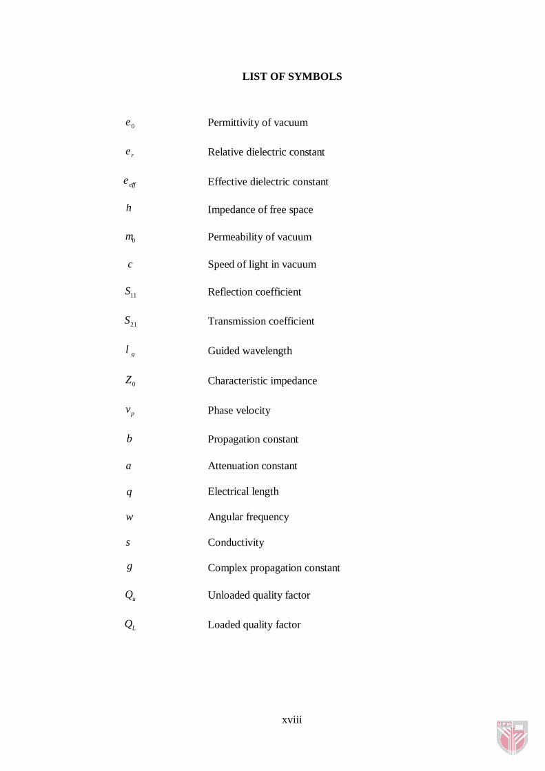
LIST OF SYMBOLS
0ε Permittivity of vacuum
rε Relative dielectric constant
effε Effective dielectric constant
η Impedance of free space
0µ Permeability of vacuum
c Speed of light in vacuum
11S Reflection coefficient
21S Transmission coefficient
gλ Guided wavelength
0Z Characteristic impedance
pv Phase velocity
β Propagation constant
α Attenuation constant
θ Electrical length
ω Angular frequency
σ Conductivity
γ Complex propagation constant
uQ Unloaded quality factor
LQ Loaded quality factor
CHAPTER 1
1 INTRODUCTION
1.1 Background
The majority of applications of today’s microwave technology are in communication,
radar, environmental remote sensing, military and medical systems. The most
universal use of microwave technology is in cellular telephone systems proposed in
the 1970s. Global Positioning Satellite (GPS) system and Direct Broadcast Satellite
(DBS) system are such successful satellite systems.
After the birth of radar, communication systems using microwave technology began
to be developed. Some advantages offered by microwave organizations, including
wide bandwidths and line-of-sight propagation, have proved to be important for both
satellite and terrestrial communications systems and also have provided the
development of low-cost miniaturized microwave components (Pozar, 2005).
Since the electromagnetic spectrum is limited and has to be shared, filters attract so
much concern due to their important roles in using the available spectrum efficiently.
The main filter functions are to select or limit the RF/microwave signals within
assigned spectral limits and to combine or separate different frequencies. Some
applications of microwave filters are in wireless and communication systems such as
satellite and cellular mobile systems. In these systems more stringent requirements
such as higher performance, lighter weight, smaller size and lower cost are desirable.
Depending on the requirements and applications, microwave filters may be designed
in various transmission line structures such as waveguide, coaxial line and
microstrip. In addition, they may be realized as distributed element or lumped
element circuits.

2
1.2 Problem Statement and Motivation
Microwave filters have important role in many wireless and communication systems
such as satellite and cellular mobile organizations. In such kind of systems some
factors in designing of microwave filters are of primary importance. Compact size,
low cost, light weight, high performance, and low loss are some of these factors that
are essentially required to enhance the system performance and to reduce the
fabrication cost (Pozar, 2005), (Hong, 2001). Parallel-coupled microstrip filters first
proposed by Cohn have been used for many years since 1958 (Hasan, 2008).
Although they have many advantages such as a wide range of filter fractional
bandwidth (FBW) of 5% to 50 %, and simple design procedure, there are still some
issues on this type of filters. Major disadvantages of this type of filter include the
length of parallel coupled filter that is too long and it further increases with the order
of filter. Some techniques have been developed to solve this problem. One of these
techniques was using hairpin-line filters including folded 2λ resonator structures
(Hasan, 2008). Afterwards, microstrip ring resonators in any shape were considered
as the building blocks of microstrip bandpass filters and in which they are widely
used, because they satisfy the mentioned demands that are essential for microwave
filters.
On the other hand, microstrip ring resonators have many interesting characteristics
including small size, low fabrication cost, and narrowband (Hsieh, 2000). In 1969,
one technique for measuring wavelengths and dispersion characteristics of the
relative permittivity of a microstrip line has been done by Troughton (Wolff, 1971)
with the help of ring resonators. Microstrip ring resonators are also used for the
measurement of phase velocity, and effective dielectric constant. Since no open-end

3
effects need to be considered in microstrip ring resonators, using them instead of the
linear resonator for dispersion measurements is more desirable (Wolff, 1971 and
Chang, 1987). In 1970 the theory of the ring resonator has been introduced by Wolff
and Knoppik. In this theory, the ring resonator has been considered as a cavity
resonator with electric walls on the top and bottom and magnetic walls on the side
border. The curvature of the ring affects the resonance frequencies and this effect
become larger by using lines with small impedances and substrate materials with
small relative permittivity. Therefore, wider resonators are more affected in the
higher-order resonances by the curvature, and as the width increases, this influence
become larger. For resonators with impedances higher than 20 Ω (for example 50,
90, and 110 Ω) the effective relative permittivity is almost independent of the length
of the resonator (Wolff, 1971). Another factor that affects the resonant frequency is
the coupling gap. To calculate the coupling gap effects on the resonant frequency,
the equivalent circuit of coupling gap that is modeled by a π - network is included in
the equivalent circuit of the ring resonator (Chang, 1987). By using this model it can
be found that as the coupling gap decreases, the resonant frequency become lower,
but for most ranges of the coupling gap size, the influences on resonant frequency
are small and negligible (Chang, 1987). The main discussing concept in this thesis is
on dual-mode ring resonators. During recent years, they have been more considered
and greatly used for microwave bandpass filter in wireless local area network
(WLAN) applications and mobile communication systems (Chen, 2007).
Microstrip dual-mode filters have many interesting characteristics, such as
narrowband, high Q, easy-to-design, and compact size. The main advantage of these
types of filters is that in dual-mode each resonator operates as a doubled tuned
resonant circuit and therefore, an n-degree filter can be achieved in more compact

4
configurations due to the halved number of resonators (Hong, 2001 and Chen,
2007). In addition to using dual-mode filters, there are some other useful methods to
achieve a compact size in filter design. One of these techniques is to have different
parts of filter bent. This could be the best solution to get more compact sizes
especially for filters with stubs and long straight transmission lines.
Ultra-wideband filter reported in (Razalli, 2008) and wideband filter reported in
(El-Shaarawy, 2008) are among the structures making use of method of bending the
lines. Although miniaturizing of microwave filters can be done by using substrates
with high dielectric constant, or lumped element or different transmission lines such
as coplanar waveguide (CPW), reduction in size with changing the geometry of the
filters using microstrip transmission lines is more desirable. This is because high
dielectric permittivity will often introduce more surface waves and losses, and while
filters using coplanar waveguide (CPW) can be found in quite compact sizes,
however they also introduce more insertion losses. Hence, microwave filters using
coplanar waveguide are seldom used in the millimetre-wave range, despite their
wide applicability in monolithic microwave integrated circuits (MMICs) due to their
ability in easily integrating series and shunt elements and simplicity of fabrication
(Ismail, 2008).
In this thesis, by applying dual-mode microstrip closed-loop resonator, a compact
narrowband bandpass filter applicable for WiMax and WLAN applications is
introduced, designed, fabricated and tested.
Table 1.1: Filter and Resonator specifications for WiMax Application
Parameters Specification Fractional Bandwidth, BW3dB 5 % Center Frequency, f0 2.3 GHz

5
Passband Insertion Loss Less than 3 dB Passband Return Loss Better than – 20 dB
The main specifications of this proposed filter is shown in Table 1.1. It is shown that
by using proper substrate material and filter structure in octagonal meander closed-
loop shape a compact filter with good performance as mentioned in Table 1.1 can be
achieved.
1.3 Research Aim and Objectives
This thesis presents a miniaturization technique of microwave filters by using dual-
mode microstrip resonators and investigates their performance comparing with other
kinds of filter structures. Even though dual-mode filters are essentially small and
compact in size, but in many applications such as cellular mobile communication
systems, much smaller size is more desirable, therefore some useful techniques can
be applied to make the dual-mode filter structure even more compact. The aim of this
thesis is to introduce and design a new configuration of compact narrowband
bandpass filter with good performance including low insertion loss and return loss,
sharp rejection and adequate bandwidth.
To achieve the aim, the main objectives of the thesis are as follows:
1. To design a compact and high performance dual-mode microstrip filter for
WiMax applications.
2. To simulate and investigate the frequency response of the filters using an
Electromagnetic Simulator software.
3. To fabricate and measure the frequency response of the filter.
1.4 Thesis Scope
As stated earlier, microwave filters are one of the most important parts of the cellular
mobile and satellite systems and in this kind of circuits, compactness and high

6
performance are of primary importance. Of course, some other parameters such as
low cost, light weight and low loss have also important role in enhancing the system
performance. In the mean time, simplicity of the designing and fabricating of the
filter structure is one of the other parameters that can be of an advantage for a filter
design.
In this thesis, the narrowband bandpass filter is designed using microstrip dual-mode
resonator. The microstrip dual-mode resonator will be constructed of a meander
closed-loop in octagonal form. The compactness will be obtained by using dual-
mode resonator and by using the dual-mode closed-loop resonator in meander form
in which more compact structure can be achieved. Using the microstrip line as the
transmission line in this filter design can make design calculation easy. By choosing
the closed-loop resonator in octagonal form the curvature effects is decreased,
compare with that in similar filter structures designed in square loop shape. The
substrate material used has good characteristics that can support the mentioned
demands such as low loss, light weight and low cost. Its high dielectric constant also
helps to have more compact size. Of course by using better materials with lower loss
tangent, lower insertion loss in passband can be achieved.
The operating frequency range of this filter makes it suitable to be used for WiMax
applications.
1.5 Scope of Research
Figure 1.1 shows an overview of the scope in this thesis to achieve the desired
compact filter structure. The solid lines in the chart exhibit the instruction followed
in this thesis to obtain our objective and the dash lines propose other directions that
are considered as different methods to minimize the filters size and make their
structure more compact