Embed Size (px)
Citation preview
Valco Instruments Co. Inc.
Rev 5/18
Universal Electric Actuator Instruction Manual Models EUH, EUD, and EUT
Valco Instruments Co. Inc.800 · 367· 8424 sales 713 · 688· 9345 tech 713 · 688· 8106 fax [email protected]
VICI AG InternationalSchenkon, Switzerland Int + 41 · 41 · 925· 6200 phone Int + 41 · 41 · 925· 6201 fax [email protected]
North America, South America, and Australia/Oceania contact: Europe, Asia, and Africa contact::
Firmware revisions EQ and subsequent

This page intentionally left blank for printing purposes
Table of Contents
Introduction Description .......................................................................................................................................... 1 Getting Started Mounting ................................................................................................................................... 1 Power Connector Function ................................................................................................. 1 Basic Operation of the Manual Remote .......................................................................... 2
Basic Control Functions with the Standard Interface .................................................................... 3 Two Positions Modes ....................................................................................................................... 3 Multiposition Mode .......................................................................................................................... 3 Step Command ....................................................................................................................... 3 Home Command .....................................................................................................................3
Optional Serial Interfaces (RS-232/485) ............................................................................................. 4 Establishing Serial Control ............................................................................................................. 4 Using the Device ID Feature .......................................................................................................... 4 Setting the Operation Mode ......................................................................................................... 5 Mode 1: Two Position With Stops ...................................................................................... 5 Mode 2: Two Position Without Stops ............................................................................... 5 Mode 3: Multiposition ........................................................................................................... 6 Serial Communication Protocol ................................................................................................... 7 Setting the Serial Port Configuration Switch .......................................................................... 7 Serial Commands .............................................................................................................................. 8 Command Reference ....................................................................................................................... 9
Optional USB Interface ...........................................................................................................................14
Optional BCD Interface ..........................................................................................................................15 Hardware Input/Output Protocols ............................................................................................15 Digital Input Protocols Binary Coded Decimal (BCD) Input Mode ...................................................................15 Parallel Input Mode ..............................................................................................................15 Binary Input Mode ...............................................................................................................15 Pin Signal Definitions ..........................................................................................................16 Additional Digital Input and Output Signals ..............................................................17
Using the Offset Feature ........................................................................................................................18 With BCD Control ............................................................................................................................18 With Serial Control ..........................................................................................................................19
Appendix A: Installing USB Drivers ...................................................................................................20 Windows XP ......................................................................................................................................20
Appendix B: Setup Mode: Using the Manual Remote to Configure the Actuator .............22 Accessing the Setup Mode ..........................................................................................................22 Button Functions .............................................................................................................................22 Examples ............................................................................................................................................22 Menu Tree ..........................................................................................................................................23
Appendix C: Factory Mode ....................................................................................................................24
Warranty .....................................................................................................................................................25

This page intentionally left blank for printing purposes
1
Introduction
Description
The VICI universal actuator models are designed to work with both two position and multiposition valves, with any number of ports. This is accomplished through simple programming via the manual remote or the optional serial, BCD, or USB interface. The actuator consists of a single unit housing a stepper motor/gearbox assembly and the control components, a universal AC input (100-240 VAC, 50-60 Hz) to 24 VDC power supply, a manual remote, and the interconnecting cables.
Getting StartedIf you ordered a valve and actuator together and will be operating the unit only with the manual remote, the first two pages of this document contain all the information you need. If you will be controlling the actuator via the standard interface or one of the optional interfaces, refer to the Table of Contents to locate the appropriate chapter.
OEM users in particular might find useful information in Appendix B: Setup Mode: Using the Manual Remote to Configure the Actuator, on page 22.
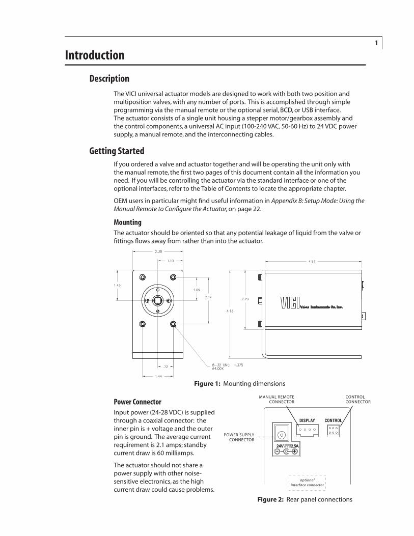
MountingThe actuator should be oriented so that any potential leakage of liquid from the valve or fittings flows away from rather than into the actuator.
Power ConnectorInput power (24-28 VDC) is supplied through a coaxial connector: the inner pin is + voltage and the outer pin is ground. The average current requirement is 2.1 amps; standby current draw is 60 milliamps.
The actuator should not share a power supply with other noise- sensitive electronics, as the high current draw could cause problems.
Figure 2: Rear panel connections
��� ����
�������
���������������������
�������
����������������������
����������������
���������������������������
Figure 1: Mounting dimensions
2
Basic Operation with the Manual Remote
The manual remote provides simple valve positioning capabilities, but in the setup mode, it can be used to execute extensive actuator setup functions. For more information, refer to Setup Mode: Using the Manual Remote to Configure the Actuator on page 22.
Do not attempt to enter the setup mode by holding down the two arrow buttons, as with a microelectric actuator. This will open a factory mode (Appendix C, page 24), which should be exited without changes by pressing the UP arrow button.
Introduction
�
� �
�
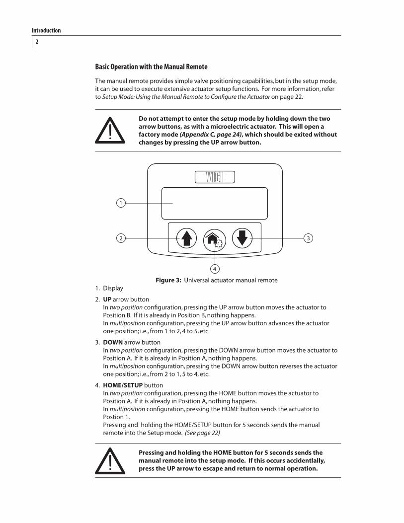
Figure 3: Universal actuator manual remote1. Display
2. UP arrow button In two position configuration, pressing the UP arrow button moves the actuator to Position B. If it is already in Position B, nothing happens. In multiposition configuration, pressing the UP arrow button advances the actuator one position; i.e., from 1 to 2, 4 to 5, etc.
3. DOWN arrow button In two position configuration, pressing the DOWN arrow button moves the actuator to Position A. If it is already in Position A, nothing happens. In multiposition configuration, pressing the DOWN arrow button reverses the actuator one position; i.e., from 2 to 1, 5 to 4, etc.
4. HOME/SETUP button In two position configuration, pressing the HOME button moves the actuator to Position A. If it is already in Position A, nothing happens. In multiposition configuration, pressing the HOME button sends the actuator to Postion 1. Pressing and holding the HOME/SETUP button for 5 seconds sends the manual remote into the Setup mode. (See page 22)
Pressing and holding the HOME button for 5 seconds sends the manual remote into the setup mode. If this occurs accidentlally, press the UP arrow to escape and return to normal operation.
3
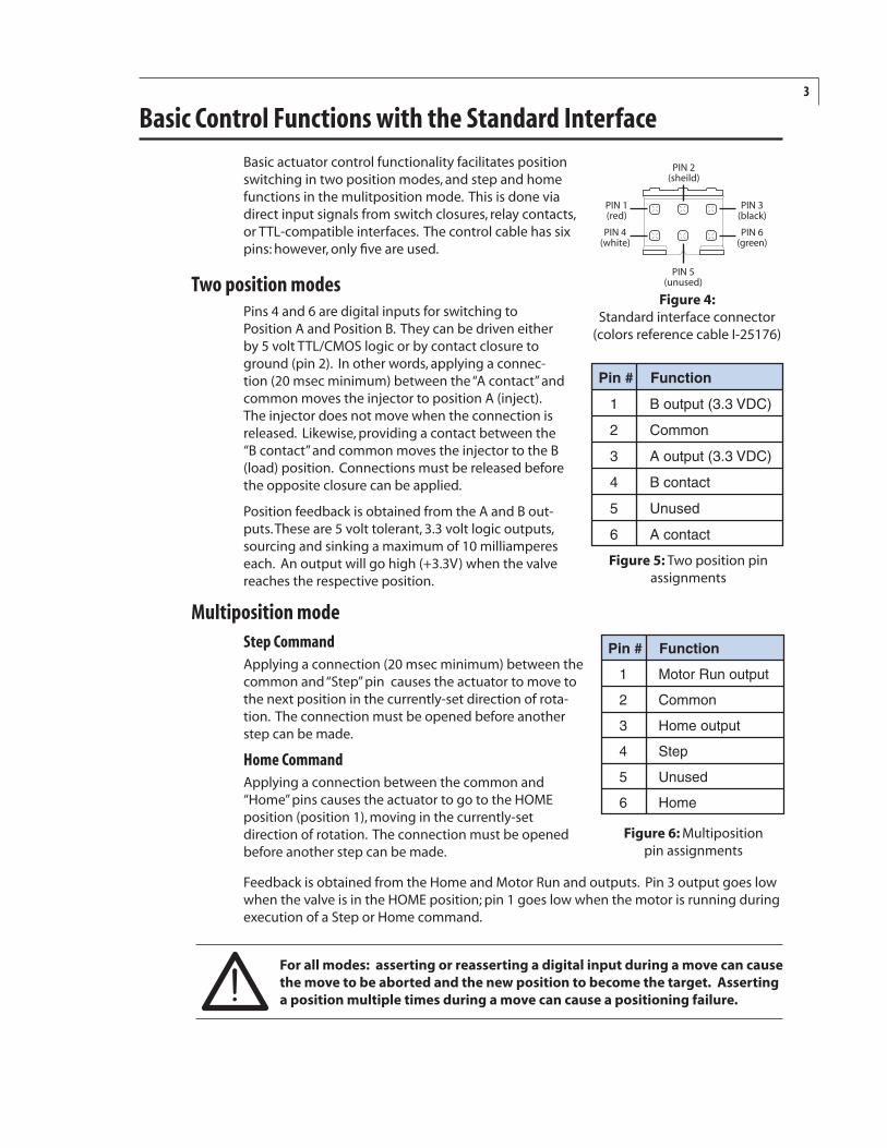
Basic Control Functions with the Standard InterfaceBasic actuator control functionality facilitates position switching in two position modes, and step and home functions in the mulitposition mode. This is done via direct input signals from switch closures, relay contacts, or TTL-compatible interfaces. The control cable has six pins: however, only five are used.
Two position modesPins 4 and 6 are digital inputs for switching to Position A and Position B. They can be driven either by 5 volt TTL/CMOS logic or by contact closure to ground (pin 2). In other words, applying a connec-tion (20 msec minimum) between the “A contact” and common moves the injector to position A (inject). The injector does not move when the connection is released. Likewise, providing a contact between the “B contact” and common moves the injector to the B (load) position. Connections must be released before the opposite closure can be applied.
Position feedback is obtained from the A and B out-puts. These are 5 volt tolerant, 3.3 volt logic outputs, sourcing and sinking a maximum of 10 milliamperes each. An output will go high (+3.3V) when the valve reaches the respective position.
Multiposition modeStep CommandApplying a connection (20 msec minimum) between the common and “Step” pin causes the actuator to move to the next position in the currently-set direction of rota-tion. The connection must be opened before another step can be made.
Home CommandApplying a connection between the common and “Home” pins causes the actuator to go to the HOME position (position 1), moving in the currently-set direction of rotation. The connection must be opened before another step can be made.
Feedback is obtained from the Home and Motor Run and outputs. Pin 3 output goes low when the valve is in the HOME position; pin 1 goes low when the motor is running during execution of a Step or Home command.
For all modes: asserting or reasserting a digital input during a move can cause the move to be aborted and the new position to become the target. Asserting a position multiple times during a move can cause a positioning failure.
������������
������������
�������� �
����������
��������� �
����������� �
����� ��������
� ������������������
� ������
� ������������������
���������
�����
� ���������
Figure 4: Standard interface connector
(colors reference cable I-25176)
Figure 5: Two position pin assignments
Figure 6: Multiposition pin assignments
����� ��������
� ����������������
� ������
� �����������
� ����
�����
����
4
Optional Serial Interfaces (RS-232/485)Note: Models with product numbers ending in “A” have been factory-set for RS-232; those ending in “F” were set for RS-485. If you wish to convert an “A” model to an “F” model or vice versa, refer to Setting the Serial Port Configuration Switch on page 7.
Establishing Serial Communication
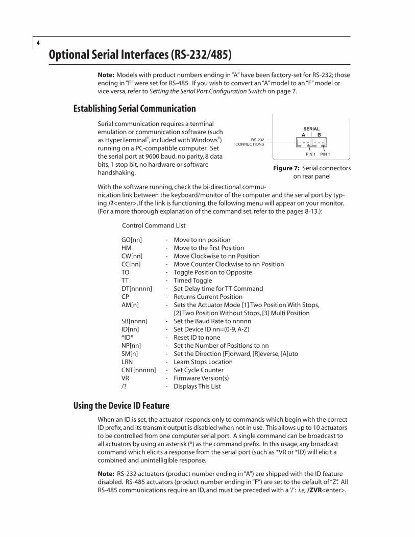
Serial communication requires a terminal emulation or communication software (such as HyperTerminal®, included with Windows®) running on a PC-compatible computer. Set the serial port at 9600 baud, no parity, 8 data bits, 1 stop bit, no hardware or software handshaking.
With the software running, check the bi-directional commu-nication link between the keyboard/monitor of the computer and the serial port by typ-ing /?<enter>. If the link is functioning, the following menu will appear on your monitor. (For a more thorough explanation of the command set, refer to the pages 8-13.):
Control Command List
GO[nn] - Move to nn position HM - Move to the first Position CW[nn] - Move Clockwise to nn Position CC[nn] - Move Counter Clockwise to nn Position TO - Toggle Position to Opposite TT - Timed Toggle DT[nnnnn] - Set Delay time for TT Command CP - Returns Current Position AM[n] - Sets the Actuator Mode [1] Two Position With Stops, [2] Two Position Without Stops, [3] Multi Position SB[nnnn] - Set the Baud Rate to nnnnn ID[nn] - Set Device ID nn=(0-9, A-Z) *ID* - Reset ID to none NP[nn] - Set the Number of Positions to nn SM[n] - Set the Direction [F]orward, [R]everse, [A]uto LRN - Learn Stops Location CNT[nnnnn] - Set Cycle Counter VR - Firmware Version(s) /? - Displays This List
Using the Device ID FeatureWhen an ID is set, the actuator responds only to commands which begin with the correct ID prefix, and its transmit output is disabled when not in use. This allows up to 10 actuators to be controlled from one computer serial port. A single command can be broadcast to all actuators by using an asterisk (*) as the command prefix. In this usage, any broadcast command which elicits a response from the serial port (such as *VR or *ID) will elicit a combined and unintelligible response.
Note: RS-232 actuators (product number ending in “A”) are shipped with the ID feature disabled. RS-485 actuators (product number ending in “F”) are set to the default of “Z”. All RS-485 communications require an ID, and must be preceded with a ‘/’: i.e, /ZVR<enter>.
Figure 7: Serial connectors on rear panel
������� �
�����������������
����������
5
For permanent multidrop applications, the RS-485 mode is the preferred solution. However, just as RS-232 control requires the host to have an RS-232 serial port, the PC host or control system must have an RS-485 port to communicate with the actuator in the RS-485 mode. Plug-in PCI cards with RS-485 ports or adaptors that change an RS-232 signal to an RS-485 signal are available from several common electronic manufacturers. If your computer lacks a serial port, adaptors which convert USB ports to RS-232 or to RS-485 are also readily available.
When installing or replacing actuators on a shared serial port, make sure that no two devices have been set to the same ID number.
To set the device ID:
1. Remove all of the actuators from the serial daisy chain except the one for which you are setting the ID.
2. To set an ID, type IDn<enter>, where n is the new ID, from 0 to 9 or A to Z. To change an ID, type i IDn<enter>, where i is the current ID and n is the new ID. To disable the ID feature, type i ID*<enter>, where i is the current ID.
Setting the Operation ModeThis section employs some simple serial commands to complete a basic configuration of the valve/actuator combination. A more advanced discussion of serial control begins in the next section.
Mode 1: Two Position With Stops (factory default)
This is the proper mode for most two position applications. (Note exceptions in the next section.) In this mode, the actuator automatically finds the correct positions using a combination of the valve’s mechanical stops and the actuator’s quadrature encoder.
To set up the actuator in this mode:
1. With no valve on the actuator, type AM1<enter> to set the actuator to Mode 1, Two Position With Stops.
2. Install the valve on the actuator. Make sure that the valve is mounted on the actuator with the stop pin all the way against the Position A stop. You can check by loosening the clamp ring and turning the valve counterclockwise by hand, then tightening the clamp ring. (For orientation, refer to the Figure 8 at the bottom of the next page.) If it will not move, it was already against the stop.
3. Type LRN<enter>. The actuator will search for the valve stops, “learning” and recording the locations. When the process is completed, the valve is set to position A.
Anytime the valve is removed from the actuator, the LRN step must be performed when the valve is reinstalled.
Mode 2: Two Position Without Stops
In this mode the actuator uses only the encoder to find the correct position. This mode is used for the Cheminert Model C32 valve and for custom applications involving on/off valves or any other two position valve that literally has no mechanical stops.
Optional Serial Interfaces (RS-232/485)
6
Optional Serial Interfaces (RS-232/485)
Installing a valve with mechanical stops with the actuator in Mode 2 could damage the actuator.
To set up the actuator in this mode:
1. With no valve on the actuator, type AM2<enter> to set the actuator to Mode 2, Two Position without Stops.
2. Type AL<enter> to move the square drive on the actuator output shaft to the proper starting position.
3. Install the valve on the actuator.
4. Type NPn<enter>, where n is the number of ports the valve has. For example, NP6<enter> tells the actuator that the valve has 6 ports, so the actuator can calculate the appropriate number of degrees from position A to position B. In this example, that distance is 60 degrees (360 / 6 ports).
Mode 3: Multiposition
Select this mode for any Valco or Cheminert multiposition valve or selector with up to 32 positions. The actuator will use its encoder to calculate the proper rotation to find each position.
Installing a valve with mechanical stops with the actuator in Mode 3 could damage the actuator.
To set up the actuator in this mode:
1. With no valve on the actuator, type AM3<enter> to set the actuator to Mode 3, Multiposition.
2. Type AL<enter> to move the square drive on the actuator output shaft to the proper starting position.
3. Install the valve on the actuator.
4. Type NPnn<enter>, where nn is the number of positions the valve has (must be an even number between 2 and 40). For example, for a 10 position valve, type NP10<enter> to set the number of positions to 10.
Do not confuse the number of positions with the number of ports. Many multiposition valves have more than one port associated with each position.
5. Type HM<enter> to send the valve to its HOME position (position 1).
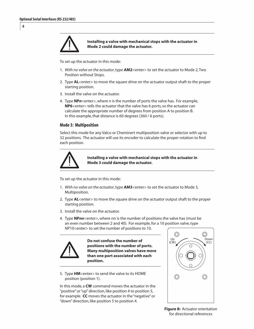
In this mode, a CW command moves the actuator in the “positive” or “up” direction, like position 4 to position 5, for example. CC moves the actuator in the “negative” or “down” direction, like position 5 to position 4.
������
��������
Figure 8: Actuator orientation for directional references
7
Optional Serial Interfaces (RS-232/485)
Serial Communication Protocol
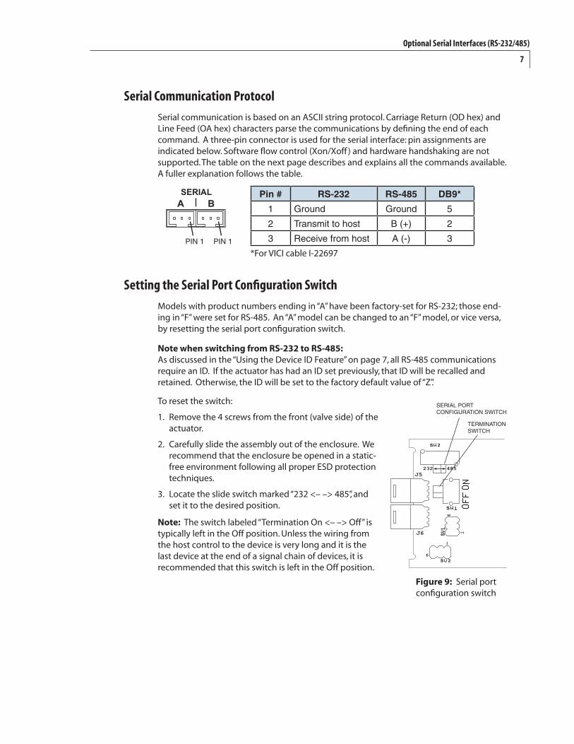
Serial communication is based on an ASCII string protocol. Carriage Return (OD hex) and Line Feed (OA hex) characters parse the communications by defining the end of each command. A three-pin connector is used for the serial interface: pin assignments are indicated below. Software flow control (Xon/Xoff ) and hardware handshaking are not supported. The table on the next page describes and explains all the commands available. A fuller explanation follows the table.
Setting the Serial Port Configuration Switch
Models with product numbers ending in “A” have been factory-set for RS-232; those end-ing in “F” were set for RS-485. An “A” model can be changed to an “F” model, or vice versa, by resetting the serial port configuration switch.
Note when switching from RS-232 to RS-485: As discussed in the “Using the Device ID Feature” on page 7, all RS-485 communications require an ID. If the actuator has had an ID set previously, that ID will be recalled and retained. Otherwise, the ID will be set to the factory default value of “Z”.
To reset the switch:
1. Remove the 4 screws from the front (valve side) of the actuator.
2. Carefully slide the assembly out of the enclosure. We recommend that the enclosure be opened in a static-free environment following all proper ESD protection techniques.
3. Locate the slide switch marked “232 <– –> 485”, and set it to the desired position.
Note: The switch labeled “Termination On <– –> Off” is typically left in the Off position. Unless the wiring from the host control to the device is very long and it is the last device at the end of a signal chain of devices, it is recommended that this switch is left in the Off position.
Pin # RS-232 RS-485 DB9*
1 Ground Ground 5
2 Transmit to host B (+) 2
3 Receive from host A (-) 3
*For VICI cable I-22697
��
��
� �
�
� �
�
�
�
��� ���
SeRiAl poRT confiGuRATion SwiTch
TeRminATion SwiTch
Figure 9: Serial port configuration switch
������� �
����������
8
Optional Serial Interfaces (RS-232/485)
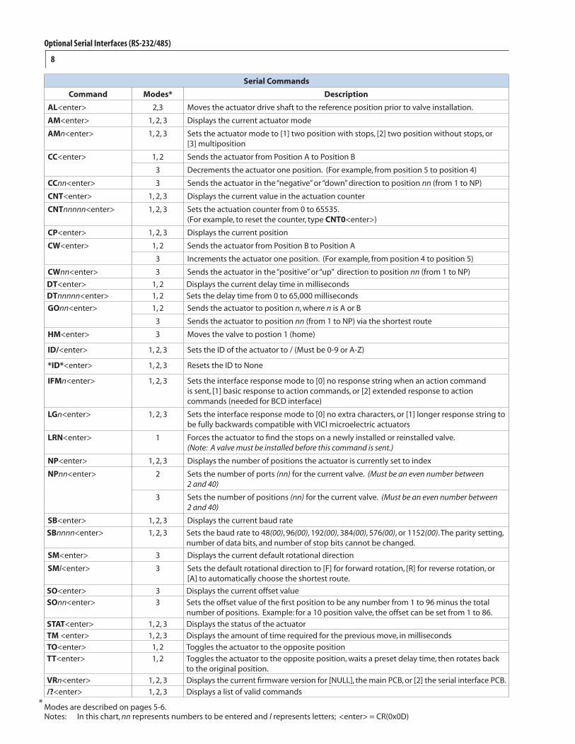
Serial Commands
Command Modes* Description
AL<enter> 2,3 Moves the actuator drive shaft to the reference position prior to valve installation.
AM<enter> 1, 2, 3 Displays the current actuator mode
AMn<enter> 1, 2, 3 Sets the actuator mode to [1] two position with stops, [2] two position without stops, or [3] multiposition
CC<enter> 1, 2 Sends the actuator from Position A to Position B
3 Decrements the actuator one position. (For example, from position 5 to position 4)
CCnn<enter> 3 Sends the actuator in the “negative” or “down” direction to position nn (from 1 to NP)
CNT<enter> 1, 2, 3 Displays the current value in the actuation counter
CNTnnnnn<enter> 1, 2, 3 Sets the actuation counter from 0 to 65535. (For example, to reset the counter, type CNT0<enter>)
CP<enter> 1, 2, 3 Displays the current position
CW<enter> 1, 2 Sends the actuator from Position B to Position A
3 Increments the actuator one position. (For example, from position 4 to position 5)
CWnn<enter> 3 Sends the actuator in the “positive” or “up” direction to position nn (from 1 to NP)
DT<enter> 1, 2 Displays the current delay time in milliseconds
DTnnnnn<enter> 1, 2 Sets the delay time from 0 to 65,000 milliseconds
GOnn<enter> 1, 2 Sends the actuator to position n, where n is A or B
3 Sends the actuator to position nn (from 1 to NP) via the shortest route
HM<enter> 3 Moves the valve to postion 1 (home)
ID/<enter> 1, 2, 3 Sets the ID of the actuator to / (Must be 0-9 or A-Z)
*ID*<enter> 1, 2, 3 Resets the ID to None
IFMn<enter> 1, 2, 3 Sets the interface response mode to [0] no response string when an action command is sent, [1] basic response to action commands, or [2] extended response to action commands (needed for BCD interface)
LGn<enter> 1, 2, 3 Sets the interface response mode to [0] no extra characters, or [1] longer response string to be fully backwards compatible with VICI microelectric actuators
LRN<enter> 1 Forces the actuator to find the stops on a newly installed or reinstalled valve. (Note: A valve must be installed before this command is sent.)
NP<enter> 1, 2, 3 Displays the number of positions the actuator is currently set to index
NPnn<enter> 2 Sets the number of ports (nn) for the current valve. (Must be an even number between 2 and 40)
3 Sets the number of positions (nn) for the current valve. (Must be an even number between 2 and 40)
SB<enter> 1, 2, 3 Displays the current baud rate
SBnnnn<enter> 1, 2, 3 Sets the baud rate to 48(00), 96(00), 192(00), 384(00), 576(00), or 1152(00). The parity setting, number of data bits, and number of stop bits cannot be changed.
SM<enter> 3 Displays the current default rotational direction
SMl<enter> 3 Sets the default rotational direction to [F] for forward rotation, [R] for reverse rotation, or [A] to automatically choose the shortest route.
SO<enter> 3 Displays the current offset value
SOnn<enter> 3 Sets the offset value of the first position to be any number from 1 to 96 minus the total number of positions. Example: for a 10 position valve, the offset can be set from 1 to 86.
STAT<enter> 1, 2, 3 Displays the status of the actuator
TM <enter> 1, 2, 3 Displays the amount of time required for the previous move, in milliseconds
TO<enter> 1, 2 Toggles the actuator to the opposite position
TT<enter> 1, 2 Toggles the actuator to the opposite position, waits a preset delay time, then rotates back to the original position.
VRn<enter> 1, 2, 3 Displays the current firmware version for [NULL], the main PCB, or [2] the serial interface PCB.
/?<enter> 1, 2, 3 Displays a list of valid commands
Modes are described on pages 5-6.Notes: In this chart, nn represents numbers to be entered and l represents letters; <enter> = CR(0x0D)
*
9
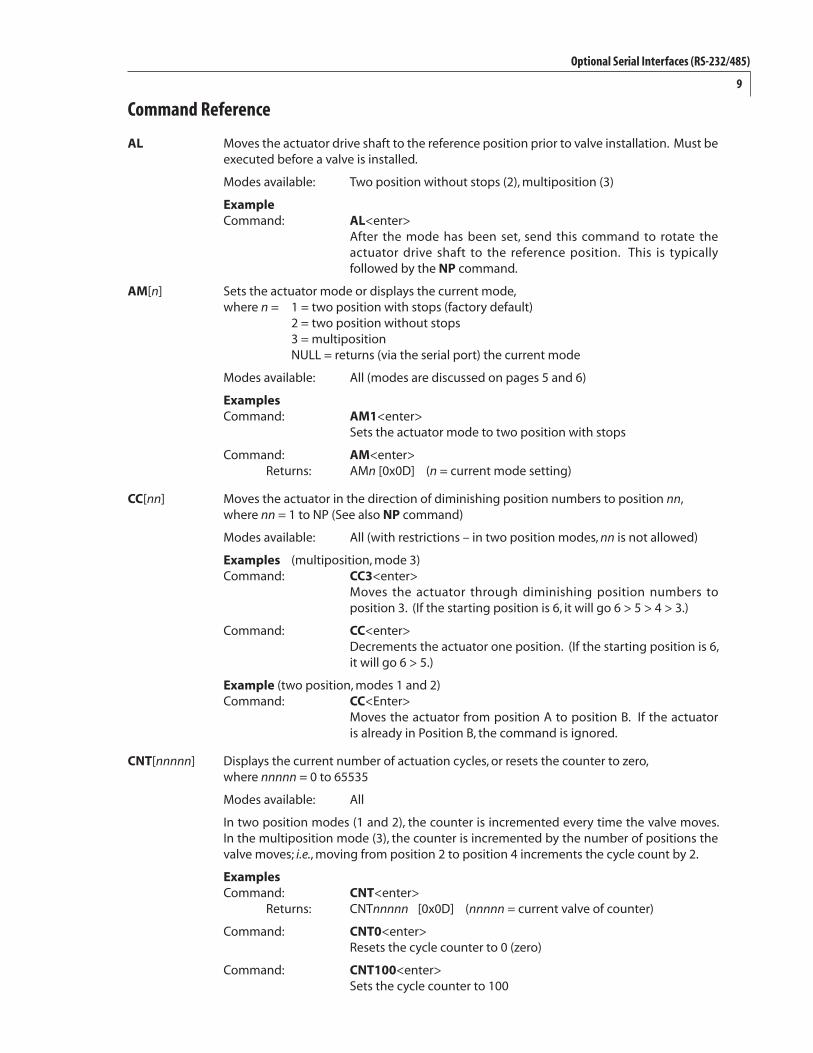
Command Reference
AL Moves the actuator drive shaft to the reference position prior to valve installation. Must be executed before a valve is installed.
Modes available: Two position without stops (2), multiposition (3)
Example Command: AL<enter> After the mode has been set, send this command to rotate the actuator drive shaft to the reference position. This is typically followed by the NP command.
AM[n] Sets the actuator mode or displays the current mode, where n = 1 = two position with stops (factory default) 2 = two position without stops 3 = multiposition NULL = returns (via the serial port) the current mode
Modes available: All (modes are discussed on pages 5 and 6)
Examples Command: AM1<enter> Sets the actuator mode to two position with stops
Command: AM<enter> Returns: AMn [0x0D] (n = current mode setting)
CC[nn] Moves the actuator in the direction of diminishing position numbers to position nn, where nn = 1 to NP (See also NP command)
Modes available: All (with restrictions – in two position modes, nn is not allowed)
Examples (multiposition, mode 3) Command: CC3<enter> Moves the actuator through diminishing position numbers to position 3. (If the starting position is 6, it will go 6 > 5 > 4 > 3.)
Command: CC<enter> Decrements the actuator one position. (If the starting position is 6, it will go 6 > 5.)
Example (two position, modes 1 and 2) Command: CC<Enter> Moves the actuator from position A to position B. If the actuator is already in Position B, the command is ignored.
CNT[nnnnn] Displays the current number of actuation cycles, or resets the counter to zero, where nnnnn = 0 to 65535
Modes available: All
In two position modes (1 and 2), the counter is incremented every time the valve moves. In the multiposition mode (3), the counter is incremented by the number of positions the valve moves; i.e., moving from position 2 to position 4 increments the cycle count by 2.
Examples Command: CNT<enter> Returns: CNTnnnnn [0x0D] (nnnnn = current valve of counter)
Command: CNT0<enter> Resets the cycle counter to 0 (zero)
Command: CNT100<enter> Sets the cycle counter to 100
Optional Serial Interfaces (RS-232/485)
10
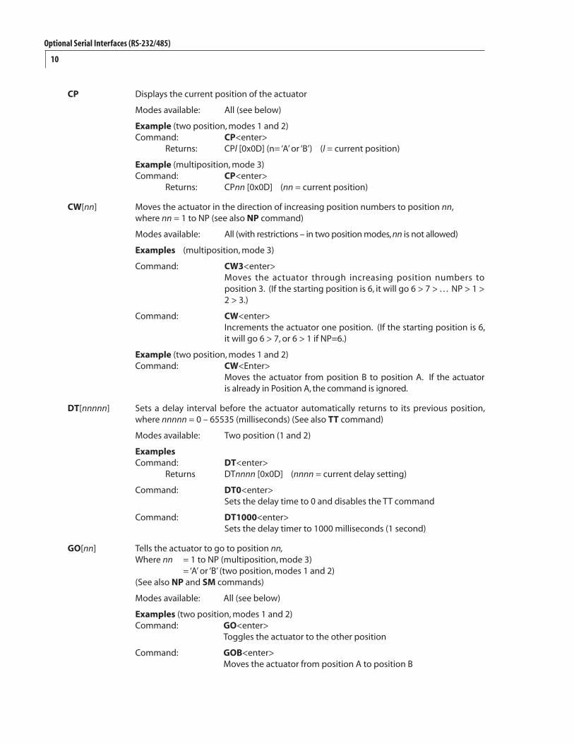
CP Displays the current position of the actuator
Modes available: All (see below)
Example (two position, modes 1 and 2) Command: CP<enter> Returns: CPl [0x0D] (n= ‘A’ or ‘B’) (l = current position)
Example (multiposition, mode 3) Command: CP<enter> Returns: CPnn [0x0D] (nn = current position)
CW[nn] Moves the actuator in the direction of increasing position numbers to position nn, where nn = 1 to NP (see also NP command)
Modes available: All (with restrictions – in two position modes, nn is not allowed)
Examples (multiposition, mode 3)
Command: CW3<enter> Moves the actuator through increasing position numbers to position 3. (If the starting position is 6, it will go 6 > 7 > . . . NP > 1 > 2 > 3.)
Command: CW<enter> Increments the actuator one position. (If the starting position is 6, it will go 6 > 7, or 6 > 1 if NP=6.)
Example (two position, modes 1 and 2) Command: CW<Enter> Moves the actuator from position B to position A. If the actuator is already in Position A, the command is ignored.
DT[nnnnn] Sets a delay interval before the actuator automatically returns to its previous position, where nnnnn = 0 – 65535 (milliseconds) (See also TT command)
Modes available: Two position (1 and 2)
Examples Command: DT<enter> Returns DTnnnn [0x0D] (nnnn = current delay setting)
Command: DT0<enter> Sets the delay time to 0 and disables the TT command
Command: DT1000<enter> Sets the delay timer to 1000 milliseconds (1 second)
GO[nn] Tells the actuator to go to position nn, Where nn = 1 to NP (multiposition, mode 3) = ‘A’ or ‘B’ (two position, modes 1 and 2) (See also NP and SM commands)
Modes available: All (see below)
Examples (two position, modes 1 and 2) Command: GO<enter> Toggles the actuator to the other position
Command: GOB<enter> Moves the actuator from position A to position B
Optional Serial Interfaces (RS-232/485)
11
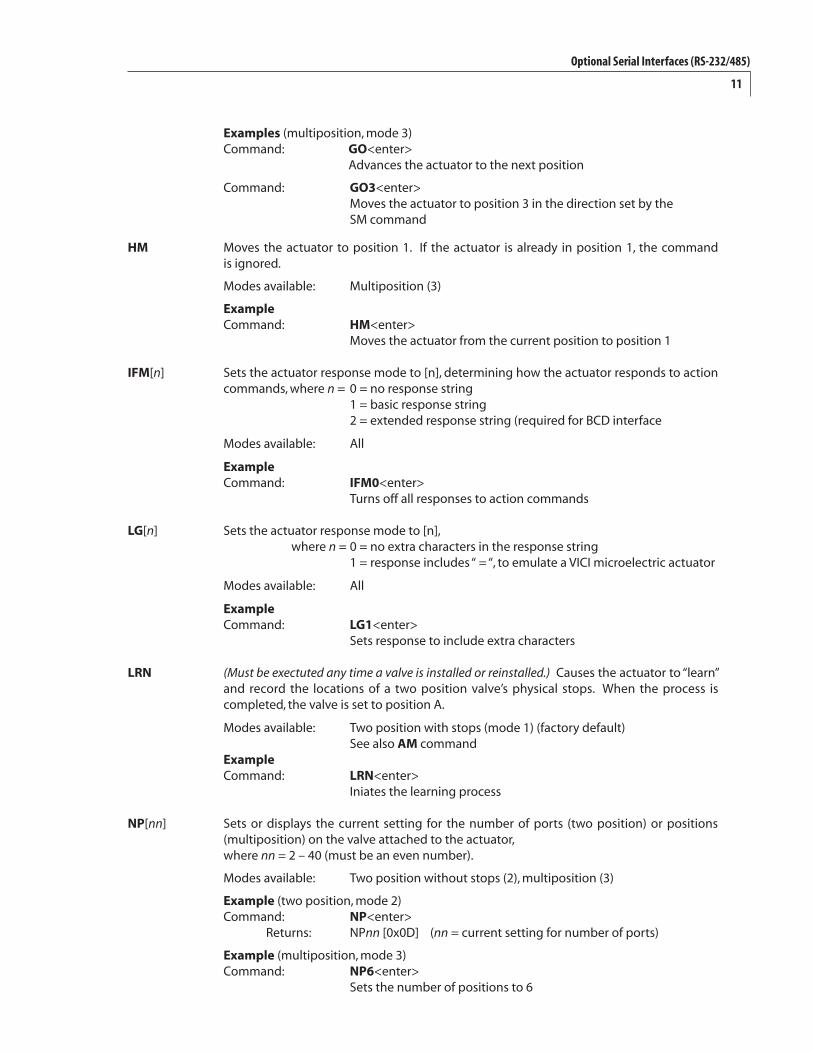
Examples (multiposition, mode 3) Command: GO<enter> Advances the actuator to the next position
Command: GO3<enter> Moves the actuator to position 3 in the direction set by the SM command
HM Moves the actuator to position 1. If the actuator is already in position 1, the command is ignored.
Modes available: Multiposition (3)
Example Command: HM<enter> Moves the actuator from the current position to position 1
IFM[n] Sets the actuator response mode to [n], determining how the actuator responds to action commands, where n = 0 = no response string 1 = basic response string 2 = extended response string (required for BCD interface
Modes available: All
Example Command: IFM0<enter> Turns off all responses to action commands
LG[n] Sets the actuator response mode to [n], where n = 0 = no extra characters in the response string 1 = response includes “ = “, to emulate a VICI microelectric actuator
Modes available: All
Example Command: LG1<enter> Sets response to include extra characters
LRN (Must be exectuted any time a valve is installed or reinstalled.) Causes the actuator to “learn” and record the locations of a two position valve’s physical stops. When the process is completed, the valve is set to position A.
Modes available: Two position with stops (mode 1) (factory default) See also AM command Example Command: LRN<enter> Iniates the learning process
NP[nn] Sets or displays the current setting for the number of ports (two position) or positions (multiposition) on the valve attached to the actuator, where nn = 2 – 40 (must be an even number).
Modes available: Two position without stops (2), multiposition (3)
Example (two position, mode 2) Command: NP<enter> Returns: NPnn [0x0D] (nn = current setting for number of ports)
Example (multiposition, mode 3) Command: NP6<enter> Sets the number of positions to 6
Optional Serial Interfaces (RS-232/485)
12
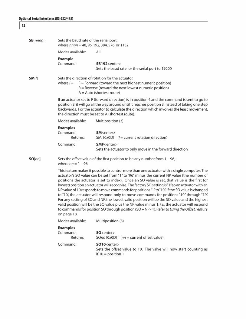
SB[nnnn] Sets the baud rate of the serial port, where nnnn = 48, 96, 192, 384, 576, or 1152
Modes available: All
Example Command: SB192<enter> Sets the baud rate for the serial port to 19200
SM[l] Sets the direction of rotation for the actuator, where l = F = Forward (toward the next highest numeric position) R = Reverse (toward the next lowest numeric position) A = Auto (shortest route)
If an actuator set to F (forward direction) is in position 4 and the command is sent to go to position 3, it will go all the way around until it reaches position 3 instead of taking one step backwards. For the actuator to calculate the direction which involves the least movement, the direction must be set to A (shortest route).
Modes available: Multiposition (3)
Examples Command: SM<enter> Returns: SMl [0x0D] (l = current rotation direction)
Command: SMF<enter> Sets the actuator to only move in the forward direction
SO[nn] Sets the offset value of the first position to be any number from 1 – 96, where nn = 1 – 96.
This feature makes it possible to control more than one actuator with a single computer. The actuator’s SO value can be set from “1” to “96”, minus the current NP value (the number of positions the actuator is set to index). Once an SO value is set, that value is the first (or lowest) position an actuator will recognize. The factory SO setting is “1”, so an actuator with an NP value of 10 responds to move commands for positions “1” to “10”. If the SO value is changed to “10”, the actuator will respond only to move commands for positions “10” through “19”. For any setting of SO and NP, the lowest valid position will be the SO value and the highest valid position will be the SO value plus the NP value minus 1; i.e., the actuator will respond to commands for position SO through position {SO + NP - 1}. Refer to Using the Offset Feature on page 18.
Modes available: Multiposition (3)
Examples Command: SO<enter> Returns SOnn [0x0D] (nn = current offset value)
Command: SO10<enter> Sets the offset value to 10. The valve will now start counting as if 10 = position 1
Optional Serial Interfaces (RS-232/485)
13
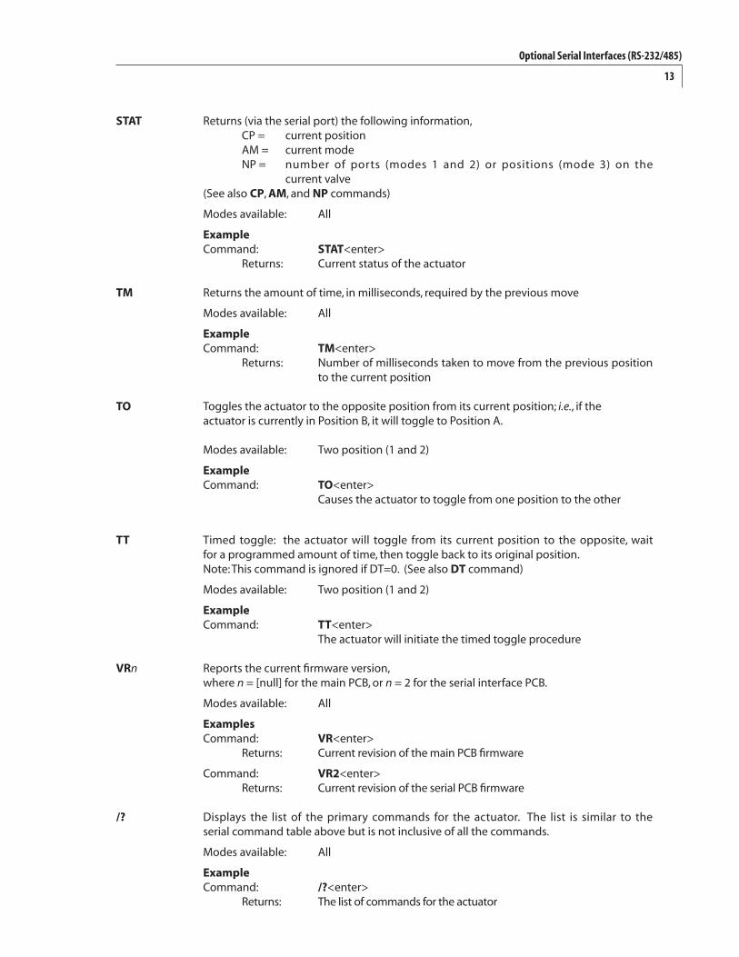
STAT Returns (via the serial port) the following information, CP = current position AM = current mode NP = number of ports (modes 1 and 2) or positions (mode 3) on the current valve (See also CP, AM, and NP commands)
Modes available: All
Example Command: STAT<enter> Returns: Current status of the actuator
TM Returns the amount of time, in milliseconds, required by the previous move
Modes available: All
Example Command: TM<enter> Returns: Number of milliseconds taken to move from the previous position to the current position
TO Toggles the actuator to the opposite position from its current position; i.e., if the actuator is currently in Position B, it will toggle to Position A.
Modes available: Two position (1 and 2)
Example Command: TO<enter> Causes the actuator to toggle from one position to the other
TT Timed toggle: the actuator will toggle from its current position to the opposite, wait for a programmed amount of time, then toggle back to its original position. Note: This command is ignored if DT=0. (See also DT command)
Modes available: Two position (1 and 2)
Example Command: TT<enter> The actuator will initiate the timed toggle procedure
VRn Reports the current firmware version, where n = [null] for the main PCB, or n = 2 for the serial interface PCB.
Modes available: All
Examples Command: VR<enter> Returns: Current revision of the main PCB firmware
Command: VR2<enter> Returns: Current revision of the serial PCB firmware
/? Displays the list of the primary commands for the actuator. The list is similar to the serial command table above but is not inclusive of all the commands.
Modes available: All
Example Command: /?<enter> Returns: The list of commands for the actuator
Optional Serial Interfaces (RS-232/485)
14
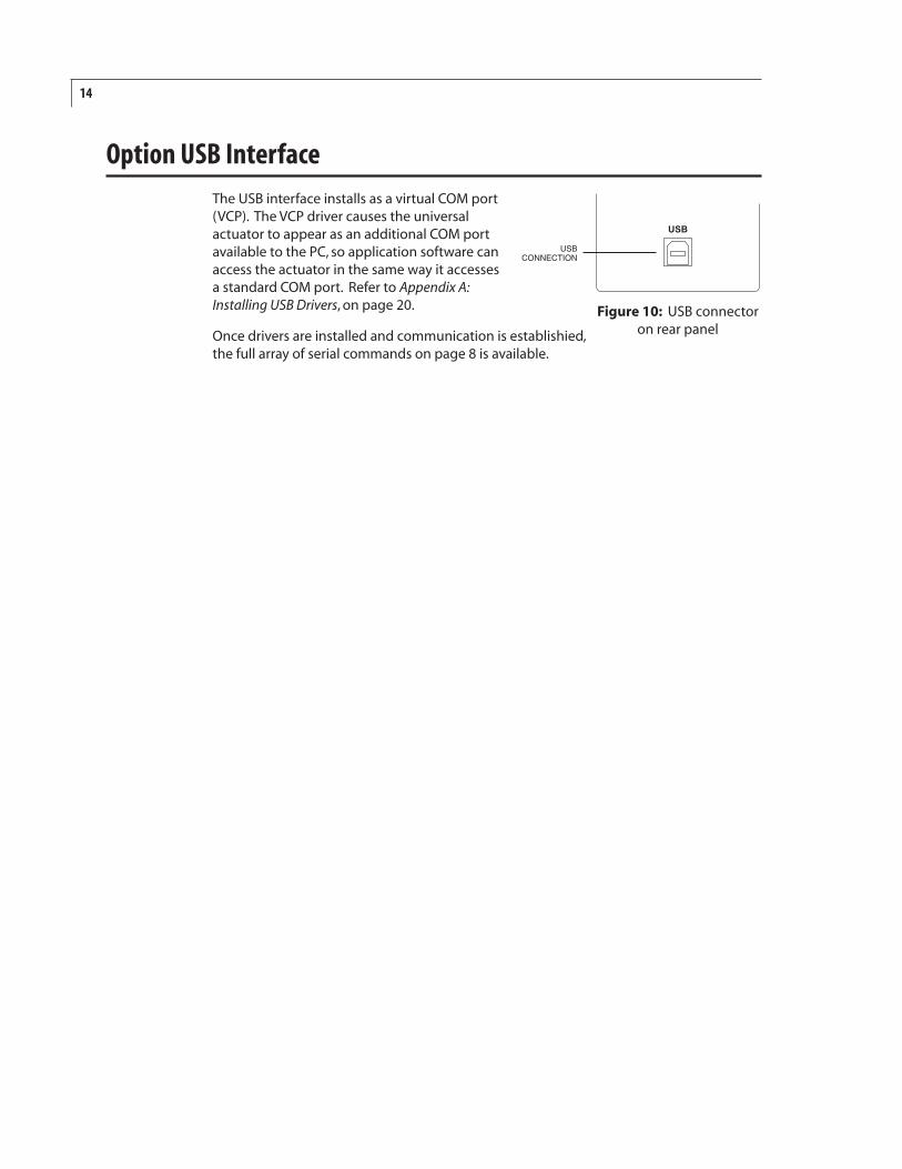
Option USB InterfaceThe USB interface installs as a virtual COM port (VCP). The VCP driver causes the universal actuator to appear as an additional COM port available to the PC, so application software can access the actuator in the same way it accesses a standard COM port. Refer to Appendix A: Installing USB Drivers, on page 20.
Once drivers are installed and communication is establishied, the full array of serial commands on page 8 is available.
���
�������������
Figure 10: USB connector on rear panel
15
Optional BCD Interface
Hardware Input / Output Protocols
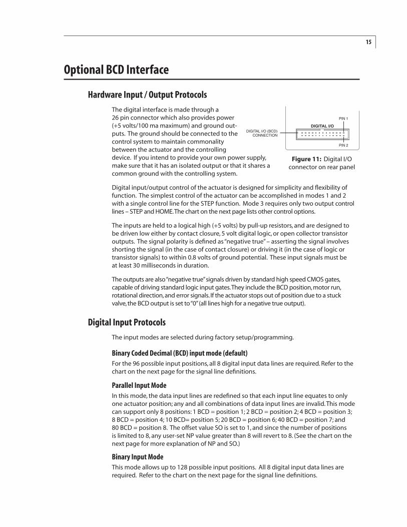
The digital interface is made through a 26 pin connector which also provides power (+5 volts/100 ma maximum) and ground out-puts. The ground should be connected to the control system to maintain commonality between the actuator and the controlling device. If you intend to provide your own power supply, make sure that it has an isolated output or that it shares a common ground with the controlling system.
Digital input/output control of the actuator is designed for simplicity and flexibility of function. The simplest control of the actuator can be accomplished in modes 1 and 2 with a single control line for the STEP function. Mode 3 requires only two output control lines – STEP and HOME. The chart on the next page lists other control options.
The inputs are held to a logical high (+5 volts) by pull-up resistors, and are designed to be driven low either by contact closure, 5 volt digital logic, or open collector transistor outputs. The signal polarity is defined as “negative true” – asserting the signal involves shorting the signal (in the case of contact closure) or driving it (in the case of logic or transistor signals) to within 0.8 volts of ground potential. These input signals must be at least 30 milliseconds in duration.
The outputs are also “negative true” signals driven by standard high speed CMOS gates, capable of driving standard logic input gates. They include the BCD position, motor run, rotational direction, and error signals. If the actuator stops out of position due to a stuck valve, the BCD output is set to “0” (all lines high for a negative true output).
Digital Input Protocols
The input modes are selected during factory setup/programming.
Binary Coded Decimal (BCD) input mode (default)For the 96 possible input positions, all 8 digital input data lines are required. Refer to the chart on the next page for the signal line definitions.
Parallel Input ModeIn this mode, the data input lines are redefined so that each input line equates to only one actuator position; any and all combinations of data input lines are invalid. This mode can support only 8 positions: 1 BCD = position 1; 2 BCD = position 2; 4 BCD = position 3; 8 BCD = position 4; 10 BCD= position 5; 20 BCD = position 6; 40 BCD = position 7; and 80 BCD = position 8. The offset value SO is set to 1, and since the number of positions is limited to 8, any user-set NP value greater than 8 will revert to 8. (See the chart on the next page for more explanation of NP and SO.)
Binary Input ModeThis mode allows up to 128 possible input positions. All 8 digital input data lines are required. Refer to the chart on the next page for the signal line definitions.
����������������������������
����������
�����
�����
Figure 11: Digital I/O connector on rear panel
16
Signal
Home
Motor run
Step
Error
Manual Dir.
Direction
Auto Dir.
Data latch
+5 VDC 100 ma
Ground
80 BCD
8 BCD
40 BCDorange
violet
gray
white
black
brown
red
brown
red
yellow
green
blue
Color
orange
Pin
1
2
3
4
5
6
7
8
9
10
11
12
13
14
15
16
17
18
19
20
21
22
23
24
25
26
Pin
green
blue
violet
gray
white
black
brown
red
green
blue
Color
yellow
orange
yellow
Direction
Input
Output
Input
Output
Input
Output
Input
Input
Output
Output
Output
Output
Output
Signal
4 BCD
20 BCD
2 BCD
10 BCD
1 BCD
80 BCD
8 BCD
40 BCD
4 BCD
20 BCD
2 BCD
10 BCD
1 BCD
Direction
Output
Output
Output
Output
Output
Input
Input
Input
Input
Input
Input
Input
Input
Mode:Input type:
Position:
SD0BCD
123456789******
10111213141516171819******
20
40
80
SD3Binary
123456789
1011121314151617181920212223242526272829303132
64
128
SD2Parallel
12*3***4*******5***************6
7
8
40 BCD––––––––––––––––––––––––––––––––
X
–
80 BCD––––––––––––––––––––––––––––––––
–
X
Data Input Lines1 BCD
X–X–X–X–X–X–X–X–X–X–X–X–X–X–X–X–
–
–
2 BCD–XX––XX––XX––XX––XX––XX––XX––XX–
–
–
4 BCD–––XXXX––––XXXX––––XXXX––––XXXX–
–
–
8 BCD–––––––XXXXXXXX––––––––XXXXXXXX–
–
–
10 BCD–––––––––––––––XXXXXXXXXXXXXXXX–
–
–
20 BCD–––––––––––––––––––––––––––––––X
–
–
Code sequence break
Code sequence break
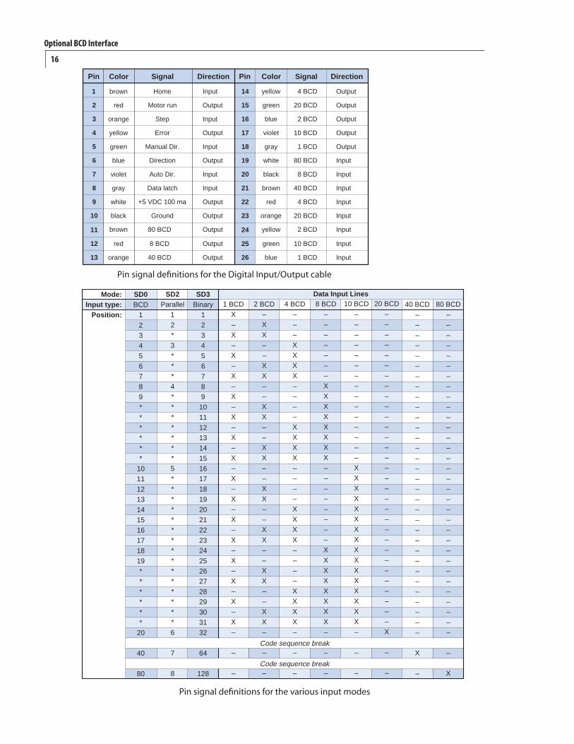
Pin signal definitions for the Digital Input/Output cable
Pin signal definitions for the various input modes
Optional BCD Interface
17
Additional Digital Input and Output Signals
Data Latch (input) Toggling this signal from high to low (hold the signal low for a minimum of 5 ms) will cause the actuator to read the BCD Input signals. Once the signals are read, the actuator will then attempt to move to the position indicated on the BCD Input signals.
BCD Signals (output) These represent the current position data in the same format used as the Input protocol.
Note: The BCD Output Signals are only updated after the motor has finished moving (see Motor Run below) and if there is no error (see Error below).
Step (input) Toggling this line from high to low (hold the signal low for a minimum of 5 ms) causes the actuator to advance one position.
Home (input) Toggling this line from high to low (hold the signal low for a minimum of 5 ms) moves the actuator to the Home (or first) position.
Manual Direction (input) When the signal is high, the actuator will move in a forward direction. For example, when moving from position 3 to position 4, it will move the shortest distance between the two positions. When the signal is low the actuator will move in a reverse direction; when moving from position 3 to position 4, it will move the longest distance between the two positions.
Auto Direction (input) When the signal is high, the Manual Direction signal dictates how the actuator moves to different positions. When the signal is low, the actuator will calculate the shortest direction between two positions and move in that direction.
Motor Run (output) When the signal is high, the motor is in an Off state. When the signal is low, the motor is in an On state (moving).
Error (output) When the signal is low, the actuator encountered an error with the last move request. When the signal is high, no error was detected.
Notes: The system considers a move request for the current position to be an error, since the motor does not move.
Error signals are cleared after the next successful move.
Direction (output) – Factory test output.
Optional BCD Interface
18
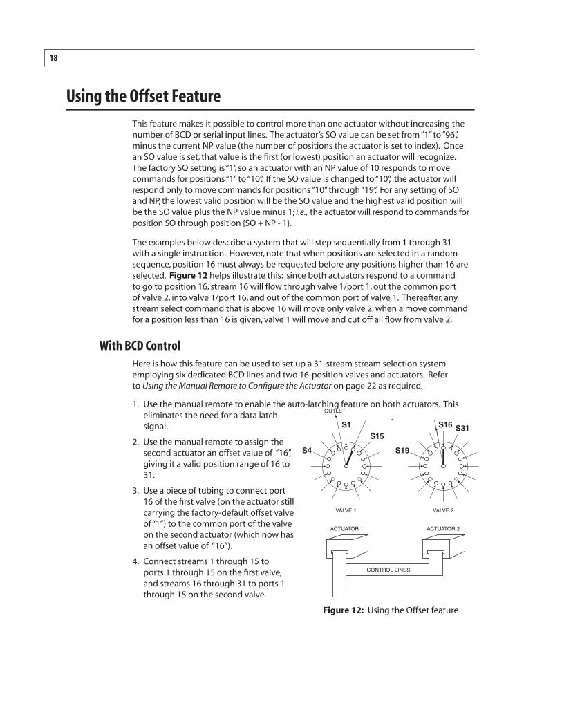
Using the Offset FeatureThis feature makes it possible to control more than one actuator without increasing the number of BCD or serial input lines. The actuator’s SO value can be set from “1” to “96”, minus the current NP value (the number of positions the actuator is set to index). Once an SO value is set, that value is the first (or lowest) position an actuator will recognize. The factory SO setting is “1”, so an actuator with an NP value of 10 responds to move commands for positions “1” to “10”. If the SO value is changed to “10”, the actuator will respond only to move commands for positions “10” through “19”. For any setting of SO and NP, the lowest valid position will be the SO value and the highest valid position will be the SO value plus the NP value minus 1; i.e., the actuator will respond to commands for position SO through position {SO + NP - 1}.
The examples below describe a system that will step sequentially from 1 through 31 with a single instruction. However, note that when positions are selected in a random sequence, position 16 must always be requested before any positions higher than 16 are selected. Figure 12 helps illustrate this: since both actuators respond to a command to go to position 16, stream 16 will flow through valve 1/port 1, out the common port of valve 2, into valve 1/port 16, and out of the common port of valve 1. Thereafter, any stream select command that is above 16 will move only valve 2; when a move command for a position less than 16 is given, valve 1 will move and cut off all flow from valve 2.
With BCD ControlHere is how this feature can be used to set up a 31-stream stream selection system employing six dedicated BCD lines and two 16-position valves and actuators. Refer to Using the Manual Remote to Configure the Actuator on page 22 as required.
1. Use the manual remote to enable the auto-latching feature on both actuators. This eliminates the need for a data latch signal.
2. Use the manual remote to assign the second actuator an offset value of “16”, giving it a valid position range of 16 to 31.
3. Use a piece of tubing to connect port 16 of the first valve (on the actuator still carrying the factory-default offset valve of “1”) to the common port of the valve on the second actuator (which now has an offset value of “16”).
4. Connect streams 1 through 15 to ports 1 through 15 on the first valve, and streams 16 through 31 to ports 1 through 15 on the second valve.
��
��
������
������
������� �������
����������
�������������
���
���
����������
Figure 12: Using the Offset feature
19
With Serial Control
Here is how this feature can be used to set up a 31-stream stream selection system employing two 16-position valves and two actuators serially daisy-chained together. Refer to the chapter on page 4 entitled Optional Serial Interfaces (RS-232-485) as required.
1. Configure the second actuator using the command SO16, giving it a valid position range of 16 to 31.
2. Use a piece of tubing to connect port 16 of the first valve (on the actuator still carrying the factory-default offset valve of “1”) to the common port of the valve on the second actuator (which now has an offset value of “16”).
3. Connect streams 1 through 15 to ports 1 through 15 on the first valve, and streams 16 through 31 to ports 1 through 15 on the second valve.
Using the Offset Feature
20
Appendix A: Installing USB Drivers
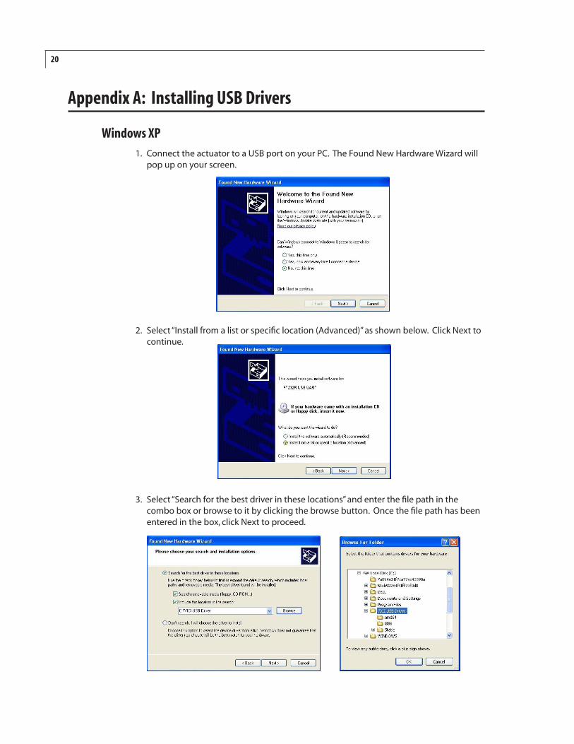
Windows XP1. Connect the actuator to a USB port on your PC. The Found New Hardware Wizard will
pop up on your screen.
2. Select “Install from a list or specific location (Advanced)” as shown below. Click Next to continue.
3. Select “Search for the best driver in these locations” and enter the file path in the combo box or browse to it by clicking the browse button. Once the file path has been entered in the box, click Next to proceed.
21
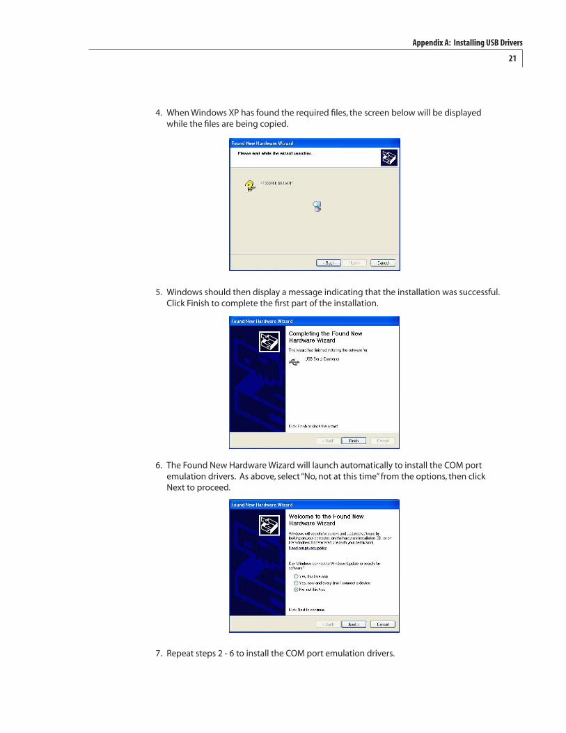
4. When Windows XP has found the required files, the screen below will be displayed while the files are being copied.
5. Windows should then display a message indicating that the installation was successful. Click Finish to complete the first part of the installation.
6. The Found New Hardware Wizard will launch automatically to install the COM port emulation drivers. As above, select “No, not at this time” from the options, then click Next to proceed.
7. Repeat steps 2 - 6 to install the COM port emulation drivers.
Appendix A: Installing USB Drivers
22
Appendix B: Setup Mode: Using the Manual Remote to Configure the Actuator
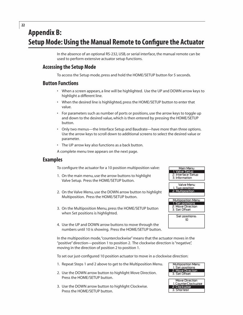
In the absence of an optional RS-232, USB, or serial interface, the manual remote can be used to perform extensive actuator setup functions.
Accessing the Setup ModeTo access the Setup mode, press and hold the HOME/SETUP button for 5 seconds.
Button Functions• Whenascreenappears,alinewillbehighlighted.UsetheUPandDOWNarrowkeysto
highlight a different line.
• Whenthedesiredlineishighlighted,presstheHOME/SETUPbuttontoenterthatvalue.
• Forparameterssuchasnumberofportsorpositions,usethearrowkeystotoggleupand down to the desired value, which is then entered by pressing the HOME/SETUP button.
• Onlytwomenus—theInterfaceSetupandBaudrate—havemorethanthreeoptions.Use the arrow keys to scroll down to additional screens to select the desired value or parameter.
• TheUParrowkeyalsofunctionsasabackbutton.
A complete menu tree appears on the next page.
ExamplesTo configure the actuator for a 10 position multiposition valve:
1. On the main menu, use the arrow buttons to highlight Valve Setup. Press the HOME/SETUP button.
2. On the Valve Menu, use the DOWN arrow button to highlight Multiposition. Press the HOME/SETUP button.
3. On the Multiposition Menu, press the HOME/SETUP button when Set positions is highlighted.
4. Use the UP and DOWN arrow buttons to move through the numbers until 10 is showing. Press the HOME/SETUP button.
In the multiposition mode, “counterclockwise” means that the actuator moves in the “positive”direction—position1toposition2.Theclockwisedirectionis“negative”, moving in the direction of position 2 to position 1.
To set our just-configured 10 position actuator to move in a clockwise direction:
1. Repeat Steps 1 and 2 above to get to the Multiposition Menu.
2. Use the DOWN arrow button to highlight Move Direction. Press the HOME/SETUP button.
3. Use the DOWN arrow button to highlight Clockwise. Press the HOME/SETUP button.
�������������������������������� �������������� �����
�������������������������� ���������������
����������������������������������������������� ���������������
�������������������������������� ����������� �������� �
����������������������������������������������� ���������������
����������������
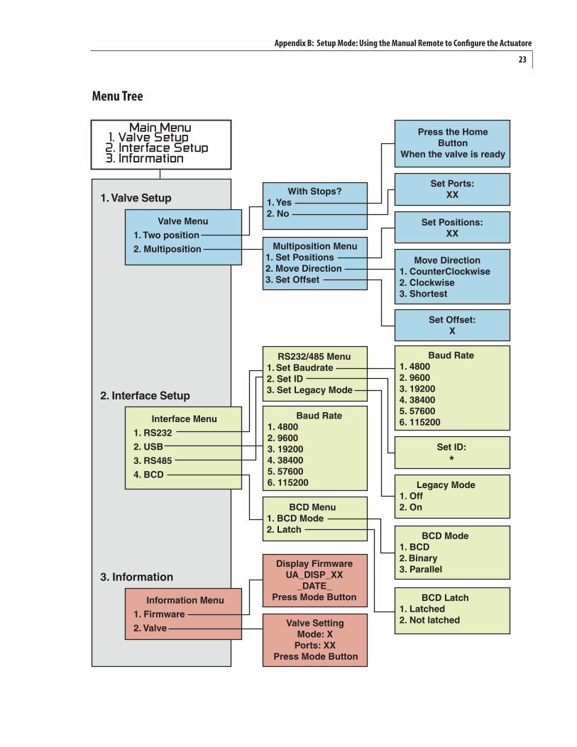
23
Menu Tree
Appendix B: Setup Mode: Using the Manual Remote to Configure the Actuatore
����������
���������������
���������������
���������
���������������
�������������������
����� �
�����
��������
������
�� � ����������������������� ������������������� �����
������������������� �����
������������������������
������ ����
�������������������
��������������������
������������
����������������������� �������������� �����
�������
�
���������������� ����������� ������������������������ ��
�������������
�������������������������������
�������
������ �������������������
���������������������������
�����������������������������
������������������
�������������� ������ �����������
���������������������������������� ��������������������������
����������������
������������������������������� ��������������������
����������
���� ��������� ����
���������������� ����������� ������������������������ ��
��������������� �����������
24
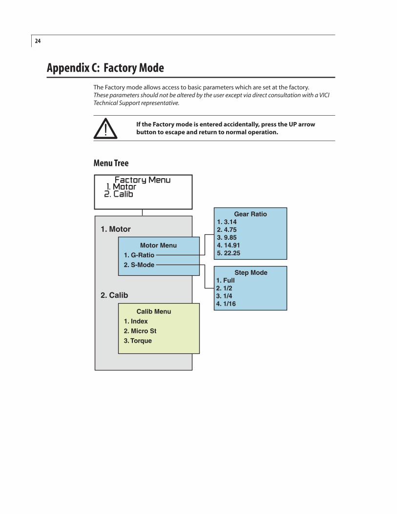
Appendix C: Factory ModeThe Factory mode allows access to basic parameters which are set at the factory. These parameters should not be altered by the user except via direct consultation with a VICI Technical Support representative.
If the Factory mode is entered accidentally, press the UP arrow button to escape and return to normal operation.
�����������������������������
������������
��� ����
������� �����������������������������������
��������
����������������
�����������������������������������������������
�����������������������������������
Menu Tree
25
WarrantyThis Limited Warranty gives the Buyer specific legal rights, and a Buyer may also have other rights that vary from state to state. For a period of 365 calendar days from the date of shipment, Valco Instruments Company, Inc. (hereinafter Seller) warrants the goods to be free from defect in material and workmanship to the original purchaser. During the warranty period, Seller agrees to repair or replace defective and/or nonconforming goods or parts without charge for material or labor, or, at the Seller’s option, demand return of the goods and tender repayment of the price. Buyer’s exclusive remedy is repair or replacement of defective and nonconforming goods, or, at Seller’s option, the repayment of the price.
Seller excludes and disclaims any liability for lost profits, personal injury, interruption of service, or for consequential incidental or special damages arising out of, resuiting from, or relating in any manner to these goods
This Limited Warranty does not cover defects, damage, or nonconformity resulting from abuse, misuse, neglect, lack of reasonable care, modification, or the attachment of im-proper devices to the goods. This Limited Warranty does not cover expendable items. This warranty is VOID when repairs are performed by a nonauthorized service center or representative. For information about authorized service centers or representatives, write Customer Repairs, Valco Instruments Company, Inc, P.O. Box 55603, Houston, Texas 77255, or phone (713) 688-9345. At Seller’s option, repairs or replacements will be made on site or at the factory. If repairs or replacements are to be made at the factory, Buyer shall return the goods prepaid and bear all the risks of loss until delivered to the factory. If Seller returns the goods, they will be delivered prepaid and Seller will bear all risks of loss until delivery to Buyer. Buyer and Seller agree that this Limited Warranty shall be governed by and construed in accordance with the laws of the State of Texas.
The warranties contained in this agreement are in lieu of all other warranties expressed or implied, including the warranties of merchantability and fitness for a particular purpose.
This Limited Warranty supercedes all prior proposals or representations oral or written and constitutes the entire understanding regarding the warranties made by Seller to Buyer. This Limited Warranty may not be expanded or modified except in writing signed by the parties hereto.