Embed Size (px)
Citation preview
SCAN UPDATE SEGMENT 18385, 18429, 18430, 18431 ROW OCS-G29100
United States Department of the Interior BUREAU OF SAFETY AND ENVIRONMENTAL ENFORCEMENT
Gulf of Mexico OCS Region 1201 Elmwood Park Boulevard
New Orleans, Louisiana 70123-2394
December 21, 2017 In Reply Refer To: GE 1035A
Mr. David Knight Union Oil Company of California 100 Northpark Blouvard Covington, Louisiana 70433
Dear Mr. Knight:
This office has reviewed your completion report dated November 21, 2014 received on December 3, 2004 for Right-of-way Pipeline Segment No. 18385 with assimilated Umbilical Segment Nos. 18429, 18430, and 18431. Additional information was received on February 29, 2016, August 1, 2017, and October 3, 2017.
Pipelines are tabulated below:
Segment Number
Size (inches)
Length (feet)
Service Origin Destination
18385 10 54,940 Bulk Oil PLET-SMS32-00 A-Jack St. Malo Walker Ridge Walker Ridge Block 677 Block 718
18429 06 61,349 Electric/Hydraulic Umbilical
A-Jack St. Malo SUTA-SMS62-00
Walker Ridge Walker Ridge Block 718 Block 677
18430 09 61,674 Electric/Hydraulic Umbilical
A-Jack St. Malo PSUT-SMS51-00
Walker Ridge Walker Ridge Block 718 Block 677
18431 06 67,596 Electri c/Hydraulic Umbilical
A-Jack St. Malo SUTA-SMN61-01
Walker Ridge Walker Ridge Block 718 Block 634
Right-of-way No. OCS-G29100
The total length of the "as-built" right-of-way is 10.41 miles.
The report is submitted in accordance with 30 CFR 250.1008 (b) and is hereby approved.

Page 2
The data provided in the report establishes the assigned maximum allowable operating pressure (MAOP) for the pipeline:
Segment MAOP MAOP Number (psig) Determination
18385 13,000 Receiving Riser Design
The high and low-pressure sensors shall be set no higher than 15 percent above and below the normal operating range, respectively. The high pilot, however, shall not be set higher than the MAOP of the pipeline. The pressure range shall be established by the use of pressure recorders.
Right-of-way No. OCS-G29100 is described as follows:
A 200-foot wide right-of-way to operate and maintain a 10.75-inch bi-directional pipeline [PF-SMS-02, Segment No. 18385], 10.41 miles in length, to transport bulk oil from a PLET [PLET-SMS32-00] in Block 677, through Blocks 676, 720, and 719 to JSM FPU in Block 718 along with one 6.9-inch O.D. Production Control Umbilical [UC-SMS02, Segment No. 18429], one Pump Power and Control Umbilical [UP-SMS-01, Segment No. 18430] and one Production Control Umbilical [UC-SMN-01, Segment No. 18431], all located in Walker Ridge Area.
Sincerely,
BIMAL SHRESTHA
Digitally signed by BIMAL SHRESTHA Date: 2017.12.21 14:01:44 -Oe'OO'
For: Bryan A. Domangue Acting Regional Supervisor Regional Field Operations

5r Chevron
Billy Varnado Project Director - Jack and St. Malo Chevron North America Deepwater Exploration & Projects
Chevron U.S.A. Inc. 1500 Louisiana Street Houston, TX 77002
November 21, 2014
Regional Supervisor, Field Operations Attn: Pipeline Section (GE 1035A) 1201 Elmwood Park Boulevard New Orleans, LA 70123-2394
RECEIVED DEC 0 2 2{m
Ofitm m nnifi npnwUum
Gentlemen:
In accordance with 30 CFR 250.1008(b), please find enclosed plats, hydrostatic test data, and
ASCII files for the JSM production pipelines as listed below. In accordance with NTL 2009-
Gl 5, a hard copy and CD with the digital data has been provided. The italicized and highlighted
future segments are not yet installed therefore details are not included at this time.
JACK Pipelines Segment Number
From To Service Permitted Length (ft)
As-Built Length (ft)
18415 (ROW) PLET-JKS32-00 (WR 758)
JSM FPU (WR 718)
Bulk Oil 58217 66726.95
18416 (ROW) PLET-JKS3 1 -00 (WR 758)
JSM FPU (WR 718)
Bulk Oil 57702 66202.09
18417 WellPSOOl (WR 758)
MFLD-JKS01-00 (WR 758)
Bulk Oil 102 Future
18418 Well PS002 (WR 758)
MFLD-JKS01-00(WR 758)
Bulk Oil 1 115 115.61
18419 WellPS004(WR 758)
MFLD-JKS01-00 (WR 758)
Bulk Oil 102 Future
18420 Well PS005 (WR 758)
MFLD-JKS01-00 (WR758)
Bulk Oil 102 101.42
18421 MFLD-JKS0I-00 (WR 758)
PTIS-JKS34-00 (WR 758)
Bulk Oil 130 131.17
18422 PTIS-JKS34-00 (WR 758)
PLET-JKS32-00 (WR 758)
Bulk Oil 120 117.57
18423 MFLD-JKS01-00 (WR 758)
PTIS-JKS33-00 (WR758)
Bulk Oil 117 120.40
18424 PTIS-JKS33-00 (WR 758)
PSTA-JKS41-00 (WR 758)
Bulk Oil 80 78.26
18425 PSTA-JK.S4I-00 (WR 758)
PTIS-JKS33-00 (WR 758)
Bulk Oil 80 79.57
18426 PTIS-JKS33-00 (WR 758)
PLET-JKS31 -00 (WR758)
Bulk Oil 120 122.49

November 21, 2014 Page 2
ST.MALO Pipelines
Segment Number
From To Service Permitted Length (ft)
As-Built Length (ft)
18385 (ROW) PLET SMS32-00 (WR 677)
JSM Platfonn (WR718)
Bulk Oil 57345 65777.65
18386 (ROW) PLET SMS31-00 (WR677)
JSM Platfonn (WR718)
Bulk Oil 57851 66282.81
18387 WellPSOOl (WR 677)
MFLD-SMS02-00 (WR 677)
Bulk Oil 102 105.30
1S3SS Well PS002 {IVR MFLD-SMS02-00 fWR 677)
Bulk Oil 102 Future
18389 Well PS003 (WR677)
MFLD-SMS02-00(WR677)
Bulk Oil 102 103.49
18390 WellPS004(WR « -
MFLD-SMS02-00 (WR 677)
Bulk Oil 102 Future
18391 PLET-SMS37-00 (WR 677)
MFLD-SMS02-00 (WR 677)
Bulk Oil 120 111.40
18392 PLET-SMS37-00 (WR 677)
MFLD-SMS02-00 (WR 677)
Bulk Oil 112 103.62
18393 WellPS005(WR 677t
MFLD-SMS01-00 (WR 677)
Bulk Oil IIS Future
18394 WallPS006(WR 67")
MFLD-SMS01-00 (WR 677)
Bulk Oil 117 Future
18395 WellPS007(WR MFLD-SMS01-00 (WR 677)
Bulk Oil 101 Future
18396 WellPSOOSfWR 677)
MFLD-SMS01-00 (WR 677)
Bulk Oil 103 Future
18397 MFLD-SMS02-00 (WR 677)
MFLD-SMS01-00(WR677)
Bulk Oil 130 137.32
18398 MFLD-SMS02-00 (WR 677)
MFLD-SMS01-00 (WR 677)
Bulk Oil 130 137.50
18399 MFLD-SMS01-00 (WR 677)
PT1S-SMS34-00 (WR 677)
Bulk Oil 118 117.29
18400 MFLD-SMS01-00 (WR 677)
PTFS-SMS33-00 (WR677)
Bulk Oil 120 116.61
18401 PTIS-SMS34-00 (WR677)
PLET-SMS32-00 (WR 677)
Bulk Oil 120 118.93
18402 PTIS-SMS33-00 (WR677)
PLET-SMS31-00 (WR 677)
Bulk Oil 120 114.44
18403 PTIS-SMS34-00 (WR 677)
PSTA-SMS42-00 (WR 677)
Bulk Oil 80 74.92
18404 PSTA-SMS42-00 (WR 677)
PT1S-SMS34-00 (WR 677)
Bulk Oil 80 75.86
18405 PTIS-SMS33-00 (WR677)
PSTA-SMS41-00 (WR 677)
Bulk Oil 80 76.21
18406 PSTA-SMS41-00 (WR 677)
PTIS-SMS33-00 (WR 677)
Bulk Oil 80 76.56
GC205 Juniper from LP Separator to Fuel Gas System

November 21, 2014 Page 3
ST. MALO Pipelines - contd.
Segment Number
From To Service Permitted Length (ft)
As-Built Length (ft)
18407 MFLD-SMMH-00 (WR 634)
PLET-SMN32-00 (WR 634)
Bulk Oil 90 88.05
18408 MFLD-SMN01-00 (WR 634)
PLET-SM"N31-00 (WR 634)
Bulk Oil 120 125.21
18409 WellPNOOl (WR 634)
MFLD-SMN01-00 (WR 634)
Bulk Oil 102 102.42
18410 WellPN002 (WR634)
MFLD-SMN01-00 (WR 634)
Bulk Oil 102 Future
18411 WellPNOOS (WR 634)
MFLD-SMNOI-00 (WR 634)
Bulk Oil 102 Future
18412 WellPNOOS (WR 634)
MFLD-SMN01-00 (WR 634)
Bulk Oil 102 Future
18413 PLET-SMN32-00 (WR 634)
PLET-SMS37-00 (WR 677)
Bulk Oil 7812 7798.51
18414 PLET-SMN31-00 (WR 634)
PLET-SMS36-00 (WR 677)
Bulk Oil 7859 7819.57
18453 PLET-SMS36-00 (WR 678)
PLET-SMS37-00 (WR 677)
Bulk Oil 120 107.93
The installed pipelines and umbilicals followed the approved route. Excess umbilical was laid down as shown on the enclosed plats.
Hydrostatic Test Data
The well jumpers and flowline jumpers were hydrostatically tested onshore for eight hours prior to installation as approved in the pipeline application. All jumpers were leak tested for two hours following installation. Flowline segments were hydrotested offshore after installation for eight hours as approved in the pipeline application. Flowline segments were tested as follows:
Flowline Segment Required Test Pressure:
12,100 X 1.25 = 15,125 psig at FPU location
Required Test Pressure: 12,100 X 1.25 = 15,125 + 3,125 (hydrostatic head at subsea test
location) = 18,250 psia
Actual Test Pressure Range
SMN 01 18414 N/A 18,250psia I8,271-18,269psia
SMN 02 18413 N/A 18,250psia 18,291-18289psia
SMS 01 18386 15,125psig N/A 15,294psig
SMS 02 18385 15,l25psig N/A 15,302psig
JKS01 18416 I5,125psig N/A 15,251 psig
JKS02 18415 15.125psig N/A 15,258psig GC205 Jumper from LP Separator to Fuel Gas System

November 21, 2014 Page 4
Documentation of all hydrostatic tests is enclosed including logs for pressure, temperature, and corresponding calibration certificates for testing instruments. No documentation from leak testing is required to be submitted.
First Operation
First Operation of the pipeline system is scheduled to occur in November 2014.
[f you have any questions or need additional information, please contact Laura Hogge at 832-298-1185 or by email at 1 aura .ho n G£(o' chevron .com.
Please send approvals to the following: GOM Business Unit Chevron U.S.A., Inc. Attn: Joe Gordon 100 Northpark Blvd. Covington, LA 70433
David Knight Facilities Manager, Jack St. Malo Chevron USA. Inc.
Enclosures: PLAT's for Pipelines. Jumpers and Umbilicals Hydrotest Data ASCII Files
GC205 Jumper from LP Separator to Fuel Gas Sjslem
BAKER HUGHES
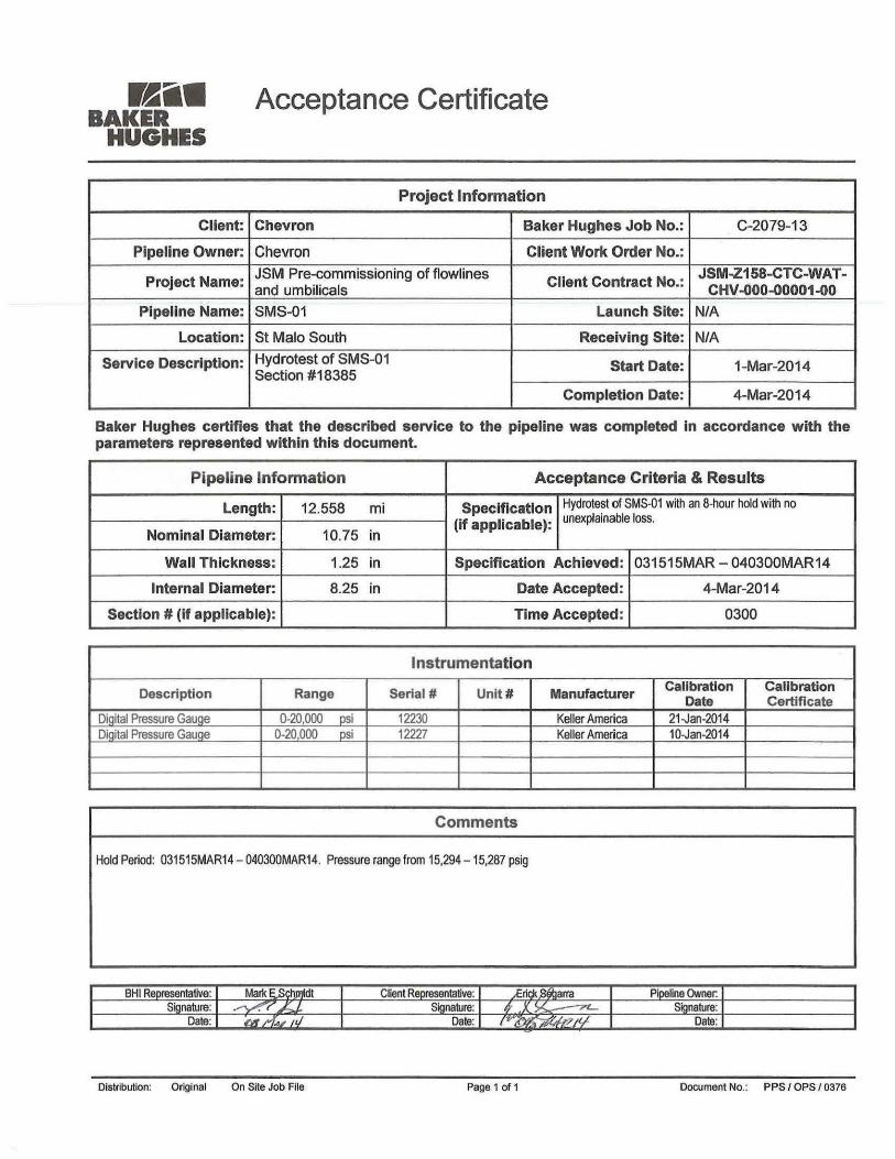
Acceptance Certificate
Project Information
Client: Chevron Baker Hughes Job No.: C-2079-13
Pipeline Owner: Chevron Client Work Order No.:
Project Name: JSM Pre-commissioning of flowlines and umbilicals
Client Contract No.: JSM-Z158-CTC-WAT-
CHV-000-00001-00
Pipeline Name: SMS-01 Launch Site: N/A
Location: St Malo South Receiving Site: N/A
Service Description: Hydrotest of SMS-01 Section #18385
Start Date: 1-Mar-2014 Service Description: Hydrotest of SMS-01 Section #18385
Completion Date: 4-Mar-2014
Baker Hughes certifies that the described service to the pipeline was completed in accordance with the parameters represented within this document.
Pipel ine Information A c c e p t a n c e Criteria & R e s u l t s
Length: 12.558 ml Specification (if applicable):
Hydrotest of SMS-01 with an 8-hour hold with no unexplainable loss.
Nominal Diameter: 10.75 in
Specification (if applicable):
Hydrotest of SMS-01 with an 8-hour hold with no unexplainable loss.
Wall Thickness: 1.25 in Specification Achieved: 031515MAR - 040300MAR14
Internal Diameter: 8.25 in Date Accepted: 4-Mar-2014
Section # (if applicable): Time Accepted: 0300
Instrumentation
Description Range Serial # Unit# Manufacturer Calibration Date
Caiibration Certificate
Diqital Pressure Gauge 0-20,000 psi 12230 Keller America 21-Jan-2014 Digital Pressure Gauge 0-20,000 psi 12227 Keller America 10-Jan-2014
Comments
Hold Period: 031515MAR14 - 040300MAR14. Pressure range from 15,294-15.287 psig
BHI Representative: Mark ESchmldt Client Representative: eriqkySetjarra Pipeline Owner. Signature: Signature: Signature:
Date: Date: Date:
Distribution: Original On Site Job File Page 1 of 1 Document No.: PPS / OPS / 0376
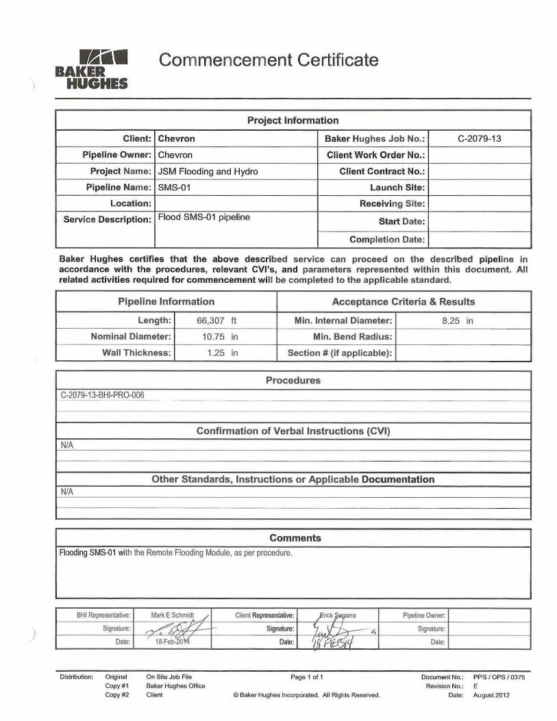
BAKER HUGHES
Commencement Certificate
Project Information
Client: Chevron Baker Hughes Job No.: C-2079-13
Pipeline Owner: Chevron Client Work Order No.:
Project Name: JSM Flooding and Hydro Client Contract No.:
Pipeline Name: SMS-01 Launch Site:
Location: Receiving Site:
Service Description: Flood SMS-01 pipeline Start Date: Service Description: Flood SMS-01 pipeline
Completion Date:
Baker Hughes certifies that the above described service can proceed on the described pipeline in accordance with the procedures, relevant CVI's, and parameters represented within this document. All related activities required for commencement will be completed to the applicable standard.
Pipeline Information Acceptance Criteria & Results
Length: 66,307 ft Min. Internal Diameter: 8.25 in
Nominal Diameter: 10.75 in Min. Bend Radius:
Wall Thickness: 1.25 in Section # (if applicable):
Procedures
C-2079-13-BHI-PRO-006
Confirmation of Verbal Instructions (CVI)
N/A
Other Standards, Instructions or Applicable Documentation N/A
Comments
Flooding SMS-01 with the Remote Flooding Module, as per procedure.
BHI Representative: Mark E Schmidt y Client Representative: £rick Segarra Pipeline Owner:
Signature: Signature: ^y^,—* Signature:
Date: IS-Feb-^OI^ Date: mm Date:
Distribution: Original Copy #1 Copy #2
On Site Job File Baker Hughes Office Client
Page 1 of 1
© Baker Hughes Incorporated. All Rights Reserved.
Document No.: PPS/OPS/0375 Revision No.: E
Date: August 2012
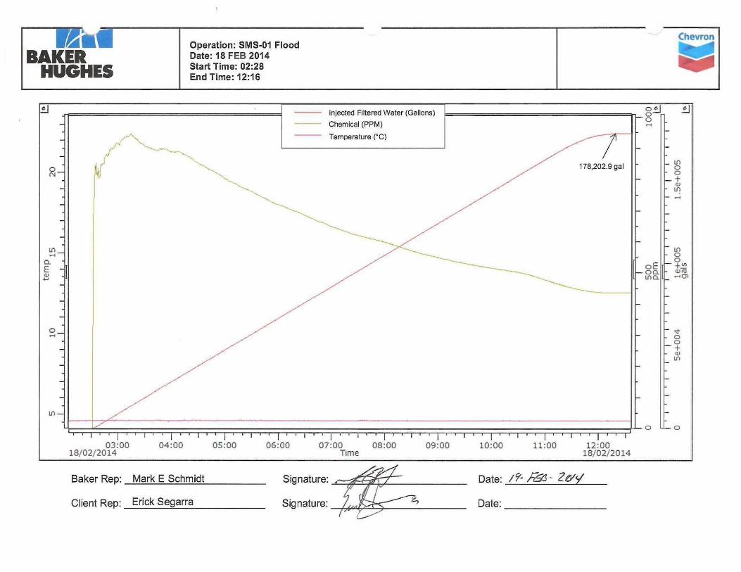
mmm Operation: SMS-01 Flood Chevron
BAKER Date: 18 FEB 2014
HUGHES Start Time: 02:28 End Time: 12:16
c
LD —
Injected Filtered Water (Gallons)
Chemical (PPM)
Temperature CO
— — 1 — | — i — i — | — r — . -
03:00 18/02/2014
04 :00 05 :00 06 :00 07 :00 Time
I 1 I 1 I 08:00 09:00 10:00
178,202.9 gal
o • o
oE oa ino.
_ LD O
h o _ + <u
h in
o • — o
in h O
O
\- O o
+ in
11:00 I 1
12:00 18/02/2014
Baker Rep: Mark E Schmidt
Client Rep: Erick Segarra
Signature: ^
Signature:
Date: / ? ' / & • ?€/</
Date:

SMS-01 Hydrotest
Pipeline Pressurisation Report (Air Inclusion) BHUGHES A c t u a l v s - Theoretical Method
Project In format ion
Client: Chevron Baker Hughes Job No.: C-2079-13
Pipeline Owner: Chevron Client Work Order No.:
Project Name: JSM - SMN Client Contract No.:
Location: SMS-01 Pipeline Volume: 179,205 gal
Length: 12.558 mile Volume/Stroke: gal
Outside Diameter: 10.75 inch Start Date: 1-Mar-2014
Section #: 1 o f l Completion Date: 1-Mar-2014
Date Time Pressure
Actual Cumulative
Volume Injected
Theoretical Volume
(P)(AV/AP)
Pipe Temp.
Remarks
(dd-Mon-yyyy) (24:00) (psig) (gal) (gal) (0F) 1-Mar-2014 16:58 0.00 0.000 0.000 Start of Pressurisation 1-Mar-2014 17:00 15.00 7.000 7.045 1-Mar-2014 17:03 30.00 38.000 14.089 1-Mar-2014 17:05 45.00 48.000 21.134 1-Mar-2014 17:08 60.00 64.000 28.179 1-Mar-2014 17:09 75.00 87.000 35.224 1-Mar-2014 17:10 90.00 101.000 42.268 1-Mar-2014 17:12 105.00 113.000 49.313 1-Mar-2014 17:13 120.00 125.000 56.358 1-Mar-2014 17:14 135.00 144.000 63.403 1-Mar-2014 17:15 150.00 161.000 70.447 1-Mar-2014 17:16 165.00 173.000 77.492 1-Mar-2014 17:18 180.00 186.000 84.537 1-Mar-2014 17:19 195.00 197.000 91.582 1-Mar-2014 17:20 210.00 202.000 98.626 1-Mar-2014 17:21 225.00 211.000 105.671 1-Mar-2014 17:23 240.00 227.000 112.716 1-Mar-2014 17:25 255.00 239.000 119.761 1-Mar-2014 17:26 270.00 251.000 126.805 1-Mar-2014 17:27 285.00 264.000 133.850 1-Mar-2014 17:28 300.00 277.000 140.895 1-Mar-2014 17:29 315.00 291.000 147.940 1-M3r-2014 17:30 330.00 302.000 154.984 1-Mar-2014 17:31 345.00 318.000 162.029 1-Mar-2014 17:33 360.00 332.000 169.074 1-Mar-2014 17:34 375.00 348.000 176.119 1-Mar-2014 17:35 390.00 361.000 183.163 1-Mar-2014 17:26 405.00 372.000 190.208 1-Mar-2014 ^ 17:37 420.00 387.000 197.253 1-Mar-2014 17:38 435.00 401.000 204.298 1-Mar-2014 17:39 450.00 418.000 211.342 1-Mar-2014 17:42 465.00 433.000 218.387 1-Mar-2014 17:44 480.00 455.000 225.432 1-Mar-2014 17:46 495.00 463.000 232.477 1-Mar-2014 17:50 510.00 487.000 239.521 1-Mar-2014 17:51 525.00 499.000 246.566
= v a = v l
> Distribution: Original On Site Job File
Copy #1 Baker Hughes Office
Copy #2 Client
Page 1 of 5
© Baker Hughes Incorporated. All Rights Reserved.
Document No.: PPS / OPS / 0330
Revision No.: E
Revision Date: July 2012

B A K E R Pipeline Pressurisation Report (Air Inclusion) -Actual vs. Theoretical Method
Pipel ine Vo lume Calculat ion
TT = Pi = 3.14159
r = ID/2 = Internal Pipeline Radius = 4.07 inch V = TT ( r 2 )L L = Pipeline Length = 12.558 mile V = TT ( r 2 )L V = Total Pipeline Volume = 179,204.71 gal
Note: For Pipelines of varied length and diameter, the Total Pipeiine Volume Is a summation of the above calculation for each section.
AV / AP Calculat ions
Check a sinqle Box below to indicate Applicable Pipeline Condition (multiple conditions require analysis outside this form to determine AV/ AP):
Se/ectecM\//AP= 0.46965
• 1 - Restrained (i.e., buried) A V
0.46768 gal/psig
_ 2 - Unrestrained (i.e., not buried or anchored) AP
0.46965 gal/psig
j—, 3 - Terminated (i.e., '—' anchored)
AV 0.46473 gal/psig
Where: Description
(Enter job-specific values below in place of defaults, as needed)
Calculated Pipeline Fill Volume V= 179204.71 gal
Theoretical Volume AV Required to Pressurise to AP AV= 7.045 gal
Incremental Pressure AP = 15.0 psig Wail Thickness t = 1.30555 inch Young's Modulus (For carbon steel) E = 3.00E+07 psig Compressibility of Fluid - (note: li = 1/K, i.e., Compressibility is reciprocal of Bulk Modulus)
fi = 2.360E-06 psi
Poisson Ratio (For carbon steel) - Dimensionless u = 0.30 non-dimensional Outside diameter 00 = 10.7500 inch Note: Allemalive pressure ranges can be used. Adjust Ihe above values accordingly (or the actual data range used.
Air Inc lus ion Calculat ions
Va = Actual Volume = 499.000 gal
Vt = Theoretical Volume = 246.566 gal ( Va.V,) \f - Mnm
V = Total Pipeline Volume = 179,204.71 gal Vdll y ( l U U j
Volume of Air % = 0.14 %
ACCEPTABLE Acceptable Air Content < 0.2%
Distribution. Original On Site Job File Copy #1 Baker Hughes Office
Page 2 of 5 Document No.: PPS / OPS / 0330
Revision No.: E
Copy 02 Client © Baker Hughes Incorporated. All Rights Reserved. Revision Date: July 2012

Pipeline Pressurisation Report (Air Inclusion) Actual vs. Theoretical Method
T h e o r e t i c a l A i r C o n t e n t G r a p h
0.00 0 50 1.00 1.50 2.00
Volume Pumped m3
2.50 3.00
Comments Ambient temperature 82F.
Distnbullon. Original: On Site Job File Page 3 of 5 Document No. PPS/OPS/0330
Copy#1: Baker Hughes Office Revision No. E
Copy #2: Client © Baker Hughes Incorporated. All Rights Reserved Revision Date July 2012

B A K E R HUGHES
Pipeline Pressurisation Report (Air Inclusion) Actual vs. Theoretical Method
Instrumentation
Description Range Serial # Unit* Manufacturer Calibration Date Calibration Certificate
Dead Weight Gauge Pressure Recorder 0-20k 4786 Tecj Cal 1/21/2014 Yes Pressure Gauge 0-20k 12227 Keller 1/10/2014 Yes
Temp. Recorder - Ambient 40F-150F 20804 Barton 10/10/2013 Yes Temp. Recorder - Pipewall Temp. Recorder - Ground
BHI Representative: Mark Schmidt Client Representative: System Owner: Signature: Signature: Signature:
Date: 3/1/14 Date: Date:
Original; On Site Job File
CopyWl Baker Hughes Office
Copy #2: Client
Page 4 of 5
© Baker Hughes Incorporated. All Rights Reserved.
Document No.. PPS/OPS/0330
Revision No.: E
Revision Dale: July 2012

BAKER HUGHES 600.0
500.0
400.0
CO
a o 300.0 3 V> (A
2 OL
200.0
Pipeline Pressurisation Report (Air Inclusion) Actual vs. Theoretical Method
100.0
0.0
• /
!
/ /
/ /
/ / / /
f
^— / /
i / / / / / /
/
/ / / /
/ /
/
/ / /
/ / /
/ /
/ /
/ / /
/ / /
/ /
/ /
—O—Actual Volume
- - - -Theoret ica l Volume
/ I
0.00 100.00 200.00 300.00
Volume Pumped (gal)
400.00 500.00 600.00
© Baker Hughes Incorporated. All Rights Reserved.
Distribution: Original: Onsite Job File Copy#1: BHI Office Copy #2: Client
page 5 of 5 Doc.#: PPS/OPS/0330 Rev. #: C
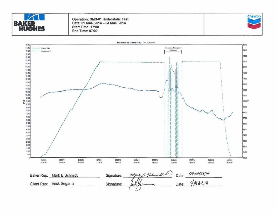
Chevron
BAKER Operation: SMS-01 Hydrostatic Test Date: 01 MAR 2014 - 04 MAR 2014
HUGHES Start Time: 17:00 End Time: 07:00
am 17,500
17,000
16,000
15,500
15,000
14,500
14,000
13,500
13,000
12.500
12.000
11 00
10.500 10.000
m 9.000
* 8.500 8.000 7.500
6.500
6.000
5.500
f,:::
4.500
4,000
sm 3.000
2,500
2,000
1,500
1,000
500
0
SwMfervtl (dd - ti:!mu AUPU): 00 • 12:00:15 AU
Prwsuro (PSI)
Temperature CF)
Troublcshool Tcmpormy i Equipment i
mw :::::: : f : : : :
02fOV14 12:00fl0
mw 03/03/14
::::::
79,00
78.00
77.00
•76.00
75.00
74.00
73.00
7100
71.00
70.00 k1-
69.00
68.00
87.00
88.00
65.00
L64.00
63.00
52 CC
3tt)V14 04«3/14 WIW
Baker Rep: Mark E Schmidt
Client Rep: Erick Segarra
Signature: m M . Sct^cK^ Date: ^ ^ g g
?, >v Date: ^MM.
• K M Chevron
maimm BAKER
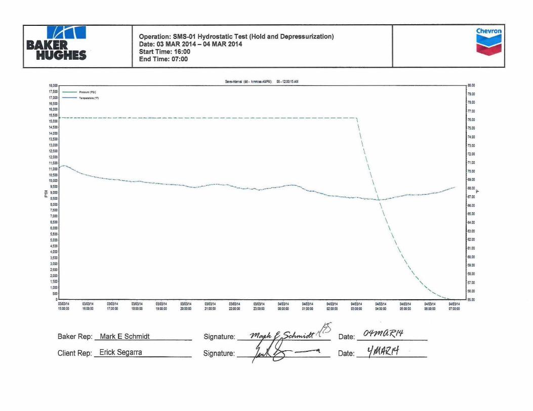
Operation: SMS-01 Hydrostatic Test (Hold and Depressurization) Date: 03 MAR 2014 - 04 MAR 2014
HUGHES Start Time: 16:00 End Time: 07:00
18.000 17,500 17,000 16,500 16,000 15,500 15,000 U,50O U.000 13,500 13,000 12500 12.000 11.500 11,000
•:::: 9.500
Ui 9,000
~ 8.500
8.000
7.500
7.000
6,500
6,000
5,500
5.000
4.500
4.000
3.500
3.000
2.500
Z000
1.500
1,000
o
Savfrrter/il (dd - IDTIICM AUPU): 00 • 12:00:15 AH MM
Prr-s-j-" 'PSI)
Temperature ('F) 79.00
78.00
77.00
76.00
75.00
74.00
73.00
72.00
71.00
70 00
69,00
68,00 ^
57,00
88.00
85.00
64 00
83 00
82,00
81,00
80.00
59.00
58.00
57.00
55.00 03/03/14 15:00:00 17:00:00
03/03/14 18:00:00 19:00:00
03/03/14 20:00 0
03 )3/14 03*3/14 03A»14 04/03/14 04*3/14 04/03/14 04A3/14 04«3r14 04rt3rt4 04*3fl4 21:00:00 22:00:00 23:00:00 00:00:00 01:00:30 02:00:00 03:00:00 04:00:00 05:00:00 06;00;00
(W0V14 IMMM
Baker Rep: Mark E Schmidt
Client Rep: Erick Segarra
Signature: j ^ ^ u K ^ Date: O ^ E E
! Date: 'jMAZfj

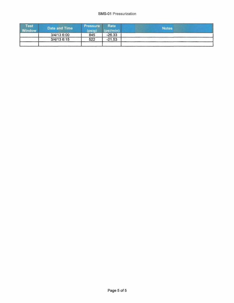
SMS-01 Pressurization
Test Date and Time
Pressure Rate Notes
Window Date and Time
(psig) (psi/min) Notes
3/1/13 18:30 508 Begin Pressurization 3/1/13 18:45 747 15.93 Ambient Temp = 82° 3/1/13 19:00 957 14.00 3/1/13 19:15 1,160 13.53 3/1/13 19:30 1.363 13.53 3/1/13 19:45 1,574 14.07 3/1/13 20:00 1,769 13.00 3/1/13 20:15 1,944 11.67 3/1/13 20:30 2,183 15.93 3/1/13 20:45 2400 3/1/13 21:00 2603 3/1/13 21:15 2857 3/1/13 21:30 3046 3/1/13 21:45 3,278 3/1/13 22:00 3,510 15.47 3/1/13 22:15 3.720 14.00 3/1/13 22:30 3,902 12.13 3/1/13 22:45 4,163 17.40 3/1/13 23:00 4.373 14.00 3/1/13 23:15 4,648 18.33 3/1/13 23:30 4,852 13.60 3/1/13 23:45 5.113 17.40 3/2/13 0:00 5,345 15.47 3/2/13 0:15 5,565 14.67 3/2/13 0:30 5.744 11.93 3/2/13 0:45 6,012 17.87 3/2/13 1:00 6.215 13.53 3/2/13 1:15 6.411 13.07 3/2/13 1:30 6.628 14.47 3/2/13 1:45 6.860 15.47 3/2/13 2:00 7.107 16.47 3/2/13 2:15 7,310 13.53 3/2/13 2:30 7,527 14.47 3/2/13 2:45 7,622 6.33 3/2/13 3:00 7.622 0.00 3/2/13 3:15 7.789 11.13 3/2/13 3:30 8.013 14.93 3/2/13 3:45 8.216 13.53 3/2/13 4:00 8.448 15.47 3/2/13 4:15 8,695 16.47 3/2/13 4:30 8,927 15.47 3/2/13 4:45 9,116 12.60 3/2/13 5:00 9.355 15.93 3/2/13 5:15 9.580 15.00 3/2/13 5:30 9.710 8.67 3/2/13 5:45 9,986 18.40 3/2/13 6:00 10,167 12.07 3/2/13 6:15 10.414 16.47 3/2/13 6:30 10,624 14.00 3/2/13 6:45 10,848 14.93 3/2/13 7:00 11,052 13.60 3/2/13 7:15 11.291 15.93 3/2/13 7:30 11,385 6.27 3/2/13 7:45 11,552 11.13
Page 1 of 5

SMS-01 Pressurization
Test Window
Date and Time Pressure
(psig) Rate
(psi/min) Notes
3/2/13 8:00 11,795 16.20 3/2/13 8:15 12,031 15.73 3/2/13 8:30 12,256 15.00 3/2/13 8:45 12,473 14.47 3/2/13 9:00 12,676 13.53 3/2/13 9:15 12,945 17.93 3/2/13 9:30 13,155 14.00 3/2/13 9:45 13,351 13.07
3/2/13 10:00 13,635 18.93 3/2/13 10:15 13,822 12.47 3/2/13 10:30 14,090 17.87 3/2/13 10:45 14,301 14.07 3/2/13 11:00 14,468 11.13 3/2/13 11:15 14,468 0.00 3/2/13 11:30 14,685 14.47 3/2/13 11:45 14,940 17.00 3/2/13 12:00 15,149 13.93 3/2/13 12:15 15,280 8.73 3/2/13 12:30 15,280 0.00 3/2/13 12:45 15,273 -0.47 3/2/13 13:00 15,273 0.00 3/2/13 13:15 15,273 0.00 3/2/13 13:30 15,265 -0.53 3/2/13 13:45 15,265 0.00 3/2/13 14:00 15,265 0.00 3/2/13 14:15 15,265 0.00 3/2/13 14:30 15,265 0.00 3/2/13 14:45 15,265 0.00 3/2/13 15:00 15,258 -0.47 3/2/13 15:15 15,258 0.00 3/2/13 15:30 15,258 0.00 3/2/13 15:45 15,251 -0.47 3/2/13 16:00 15,251 0.00 3/2/13 16:15 15,251 0.00 3/2/13 16:30 15,251 0.00 3/2/13 16:45 15,251 0.00 3/2/13 17:00 15,251 0.00 3/2/13 17:15 15,243 -0.53 3/2/13 17:30 15,243 0.00 3/2/13 17:45 15,243 0.00 3/2/13 18:00 15,243 0.00 3/2/13 18:15 15,243 0.00 3/2/13 18:30 15,243 0.00 3/2/13 18:45 15,243 0.00 3/2/13 19:00 15,243 0.00 3/2/13 19:15 15,236 -0.47 3/2/13 19:30 15,236 0.00 3/2/13 19:45 15,236 0.00 3/2/13 20:00 15,236 0.00 3/2/13 20:15 15,236 0.00 3/2/13 20:30 15,236 0.00 3/2/13 20:45 15,236 0.00 3/2/13 21:00 15,229 -0.47 3/2/13 21:15 15,229 0.00
Page 2 of 5

SMS-01 Pressurization
Test Window
Date and Time Pressure
(psig) Rate
(psi/min) 3/2/13 21:30 15,229 0.00 3/2/13 21:45 15,229 0.00 3/2/13 22:00 15,229 0.00 3/2/13 22:15 15,229 0.00 3/2/13 22:30 15,229 0.00 3/2/13 22:45 15,229 0.00 3/2/13 23:00 15,229 0.00 3/2/13 23:15 15,229 0.00 3/2/13 23:30 15,222 -0.47 3/2/13 23:45 15,222 0.00 3/3/13 0:00 15,222 0.00 3/3/13 0:15 15,222 0.00 3/3/13 0:30 15,222 0.00 3/3/13 0:45 15,222 0.00 3/3/13 1:00 15,222 0.00 3/3/13 1:15 15.222 0.00 3/3/13 1:30 15,222 0.00 3/3/13 1:45 15,222 0.00 3/3/13 2:00 15.214 -0.53 3/3/13 2:15 15,214 0.00 3/3/13 2:30 15,214 0.00 3/3/13 2:45 15,214 0.00 3/3/13 3:00 15,214 0.00 3/3/13 3:15 15,214 0.00 3/3/13 3:30 15,214 0.00 3/3/13 3:45 15.214 0.00 3/3/13 4:00 15,214 0.00 3/3/13 4:15 15.207 -0.47 3/3/13 4:30 15,207 0.00 3/3/13 4:45 15,207 0.00 3/3/13 5:00 15,207 0.00 3/3/13 5:15 15,207 0.00 3/3/13 5:30 15,207 0.00 3/3/13 5:45 15,207 0.00 3/3/13 6:00 15,207 0.00 3/3/13 6:15 15,207 0.00 3/3/13 6:30 15,207 0.00 3/3/13 6:45 15,207 0.00 3/3/13 7:00 15,207 0.00 3/3/13 7:15 15,207 0.00 3/3/13 7:30 15,200 -0.47 3/3/13 7:45 15,200 0.00 3/3/13 8:00 15,178 -1.47 3/3/13 8:15 15,171 -0.47 3/3/13 8:30 15,156 -1.00 3/3/13 8:45 15,149 -0.47 3/3/13 9:00 15,142 -0.47
3/3/13 15:00 15,294 3/3/13 15:15 15,294 0.00 3/3/13 15:30 15,294 0.00 3/3/13 15:45 15,294 0.00 3/3/13 16:00 15.294 0.00 3/3/13 16:15 15,294 0.00
Page 3 of 5

SMS-01 Pressurization
Test Date and Time
Pressure Rate Notes
Window Date and Time
(psig) (psi/min) Notes
3/3/13 16:30 15.294 0.00 3/3/13 16:45 15.294 0.00 3/3/13 17:00 15,294 0.00 3/3/13 17:15 15,294 0.00 3/3/13 17:30 15,294 0.00 3/3/13 17:45 15,294 0.00 3/3/13 18:00 15.294 0.00 3/3/13 18:15 15,294 0.00 3/3/13 18:30 15.294 0.00 3/3/13 18:45 15,294 0.00 3/3/13 19:00 15,294 0.00 3/3/13 19:15 15.294 0.00 3/3/13 19:30 15,294 0.00 3/3/13 19:45 15.294 0.00 3/3/13 20:00 15,294 0.00 3/3/13 20:15 15,294 0.00 3/3/13 20:30 15,294 0.00 3/3/13 20:45 15,294 0.00 3/3/13 21:00 15,294 0.00 3/3/13 21:15 15,294 0.00 3/3/13 21:30 15.294 0.00 3/3/13 21:45 15,294 0.00 3/3/13 22:00 15,294 0.00 3/3/13 22:15 15,294 0.00 3/3/13 22:30 15,294 0.00 3/3/13 22:45 15,294 0.00 3/3/13 23:00 15,294 0.00 3/3/13 23:15 15,294 0.00 3/3/13 23:30 15,294 0.00 3/3/13 23:45 15,294 0.00 3/4/13 0:00 15,294 0.00 3/4/13 0:15 15,294 0.00 3/4/13 0:30 15,294 0.00 3/4/13 0:45 15,294 0.00 3/4/13 1:00 15,294 0.00 3/4/13 1:15 15,294 0.00 3/4/13 1:30 15,294 0.00 3/4/13 1:45 15,294 0.00 3/4/13 2:00 15,287 -0.47 3/4/13 2:15 15,287 0.00 3/4/13 2:30 15,287 0.00 3/4/13 2:45 15,287 0.00 3/4/13 3:00 15,287 0.00 3/4/13 3:15 13,097 -146.00 3/4/13 3:30 11,211 -125.73 3/4/13 3:45 9,529 -112.13 3/4/13 4:00 7,984 -103.00 3/4/13 4:15 6,546 -95.87 3/4/13 4:30 5.366 -78.67 3/4/13 4:45 4,148 -81.20 3/4/13 5:00 3.358 -52.67 3/4/13 5:15 2,371 -65.80 3/4/13 5:30 1.762 -40.60 3/4/13 5:45 1,240 -34.80
Page 4 of 5
SMS-01 Pressurization
Test Window
Date and Time Pressure
(psig) Rate
(psi/min) Notes
3/4/13 6:00 845 -26.33 3/4/13 6:15 522 -21.53
Page 5 of 5

SMS-01 Hold and Depressurization 18,000
16,000
14,000
12,000
10,000
8,000
6,000
4,000
2,000
0
^ ^ ^ ^ ^ ^ ^ ^ ^ ^ ^ ^ ^ ^ J* ^ # # # # # # # # # # r r r r # r r r #
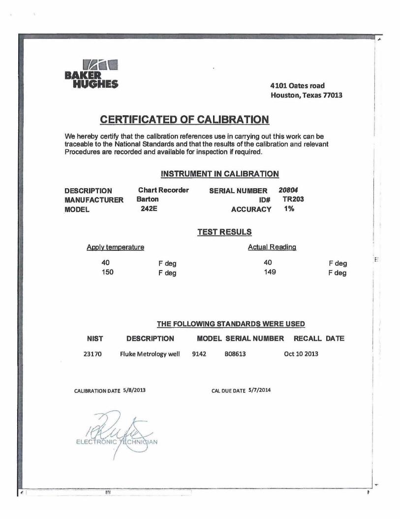
BAKER HUGHES 4101 Oates road
Houston, Texas 77013
CERTIFICATED OF CALIBRATION We hereby certify that the calibration references use in carrying out this work can be traceable to the National Standards and that the results of the calibration and relevant Procedures are recorded and available for inspection if required.
INSTRUMENT IN CALIBRATION
DESCRIPTION MANUFACTURER MODEL
Chart Recorder Barton
242E
SERIAL NUMBER 20804 ID# TR203
ACCURACY 1%
ADPIV temperature
40 F deg 150 F deg
TEST RESULS
Actual Reading
40 149
Fdeg F deg
THE FOLLOWING STANDARDS WERE USED
NIST DESCRIPTION MODEL SERIAL NUMBER RECALL DATE
23170 Fluke Metrology well 9142 B08613 Oct 10 2013
CALIBRATION DATE 5/8/2013 CAL DUE DATE 5/7/2014
IAN

BAKER HUGHES 4101 Oates road
Houston, Texas 77013
CERTIFICATED OF CALIBRATION We hereby certify that the calibration references use in carrying out this work can be traceable to the National Standards and that the results of the calibration and relevant Procedures are recorded and available for inspection if required.
INSTRUMENT IN CALIBRATION
DESCRIPTION MANUFACTURER MODEL
Chart Recorder Barton
242E
SERIAL NUMBER E07-009 |D# TR200
ACCURACY 1%
Apply t^mperatMro
40 F deg 150 Fdeg
TEST RESULS
Actual Readino
42 149
Fdeg Fdeg
THE FOLLOWING STANDARDS WERE USED
NIST DESCRIPTION MODEL SERIAL NUMBER RECALL DATE
23170 Fluke Metrology well 9142 B08613 Oct 10 2013
CALIBRATION DATE 7/17/2013 CAL DUE DATE 7/16/2014
ELECTRONIC Tl
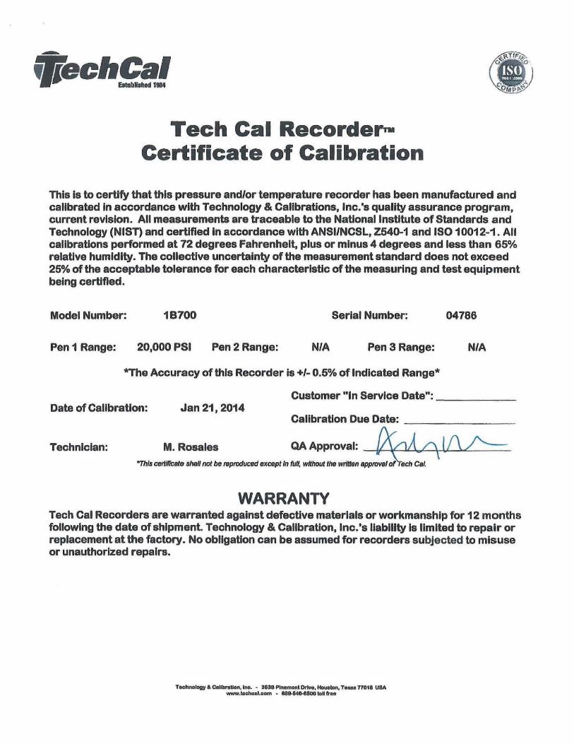
IMechCal JW Establish ed 1964
Tech Cal Recorder-Certificate of Calibration
This is to certify that this pressure and/or temperature recorder has been manufactured and calibrated in accordance with Technology & Calibrations, inc.'s quality assurance program, current revision. All measurements are traceable to the National Institute of Standards and Technology (NIST) and certified in accordance with ANSI/NCSL, Z640-1 and IS010012-1. All calibrations performed at 72 degrees Fahrenheit, plus or minus 4 degrees and less than 65% relative humidity. The collective uncertainty of the measurement standard does not exceed 25% of the acceptable tolerance for each characteristic of the measuring and test equipment being certified.
Model Number: 1B700 Serial Number: 04786
Pen 1 Range: 20,000 PSI Pen 2 Range: N/A Pen 3 Range: N/A
*The Accuracy of this Recorder Is +/- 0.6% of indicated Range*
Customer "In Service Date": Date of Calibration: Jan 21,2014
Calibration Due Date:
Technician: M. Resales OA Approval: / / V V . / ^ [ A y ^ This certificate shall not be reproduced except In full, without the written approval of Tech Cal.
WARRANTY Tech Cal Recorders are warranted against defective materials or workmanship for 12 months following the date of shipment. Technology & Calibration, Inc.'s liability Is limited to repair or replacement at the factory. No obligation can be assumed for recorders subjected to misuse or unauthorized repairs.
Toohnelofly & Calibration, Ino. - 363BPInamant Drive, Houaton, Toms 77018 USA www.toehoal.oom - MB-MO-BSOa toll frea

BAKER Test Certificate
We hereby certify that the calibration references used in carrying out this work can be traceable to the National Standards and that the results of the calibration and relevant Procedures are recorded and available for inspection if required.
INSTRUMENT IN CALIBRATION
Instrument ID # Manufacturer Description
K103 Keller America Digital pressure gauge
Model Serial Number Accuracy
Leo Rec 12227
0.1%
T E S T R E S U L T S
Applied Pressure Actual reading
o 19000
PSIG PSIG
PSIG PSIG
0 18993
THE FOLLOWING STANDARDS WERE USED
NIST DESCRIPTION MODEL 26534 Digital Pressure gauge Leo Rec
S/N 9101
CAL DUE CATE 11/15/2014
Calibration Date January 10 2014 Cal due date January 09 2015
ELECTRONIC / ^ C H N I Q I A N

iffechCal Establiihsd 1984
Tech Cal Recorder-Certificate of Calibration
This is to certify that this pressure and/or temperature recorder has been manufactured and calibrated in accordance with Technology & Calibrations, Inc.'s quality assurance program, current revision. All measurements are traceable to the National Institute of Standards and Technology (NIST) and certified in accordance with ANSI/NCSL. Z540-1 and IS010012-1. All calibrations performed at 72 degrees Fahrenheit, plus or minus 4 degrees and less than 65% relative humidity. The collective uncertainty of the measurement standard does not exceed 25% of the acceptable tolerance for each characteristic of the measuring and test equipment being certified.
Model Number: 1B700 Serial Number: 04785
Pen 1 Range: 20,000 PSI Pen 2 Range: N/A Pen 3 Range: N/A
*The Accuracy of this Recorder is +/- 0.5% of Indicated Range*
Customer "In Service Date": Date of Calibration: Jan 21,2014
Calibration Due Date:
Technician: M. Resales OA Approval: 'This certificate shall not be reproduced except In full, without the written approval of Tech Cal.
WARRANTY Tech Cal Recorders are warranted against defective materials or workmanship for 12 months following the date of shipment Technology & Calibration, Inc.'s liability is limited to repair or replacement at the factory. No obligation can be assumed for recorders subjected to misuse or unauthorized repairs.
Technology & Calibration, Inc. • 3638 Plnemont Drive, Houaton, Texas 7701B USA www.techcal.oom - 088-540-8600 toll free

4101 Oates Road Houston. Texas 77013
HUGHES CERTIFICATE OF CALIBRATION
The manufacturer's specifications for the below Instrument have been confirmed by comparation to standards which are regularly calibrated using accepted values of natural physical constansts, ratio type self -calibrating techniques, comparasion to standards whish are traceable to National Institute of Standards and Technology (NIST), or compared to consensus standards
INSTRUMENT IN CALIBRATION
TEST RESULTS
Applied Pressure PSIG
0 19000
Actual Reading
0.00 18990
THE FOLLOWING STADARDS WERE USED
NIST DESCRIPTION MANUF MODEL 26534 Digital Gauge Keller America Leo Rec
S/N 9101
RECALL DATE Nov 15 2014
Calibration bate 1 ' ] January 21 2014
SI: Roberto Romero Electronic Tech
Cal Due Date January 20 2015