Embed Size (px)
Citation preview
05/09/2012 Unit.4.Harmonics 1
Dr.S.S.DashDr.S.S.Dash
Professor & HOD/EEE,Professor & HOD/EEE,Department of Electrical and Electronics Engg.,Department of Electrical and Electronics Engg.,
SRM University,SRM University,
ChennaiChennai--203203
Unit.4Unit.4-- HarmonicsHarmonics
05/09/2012 Unit.4.Harmonics 2
UNIT-4. HARMONICS - syllabus
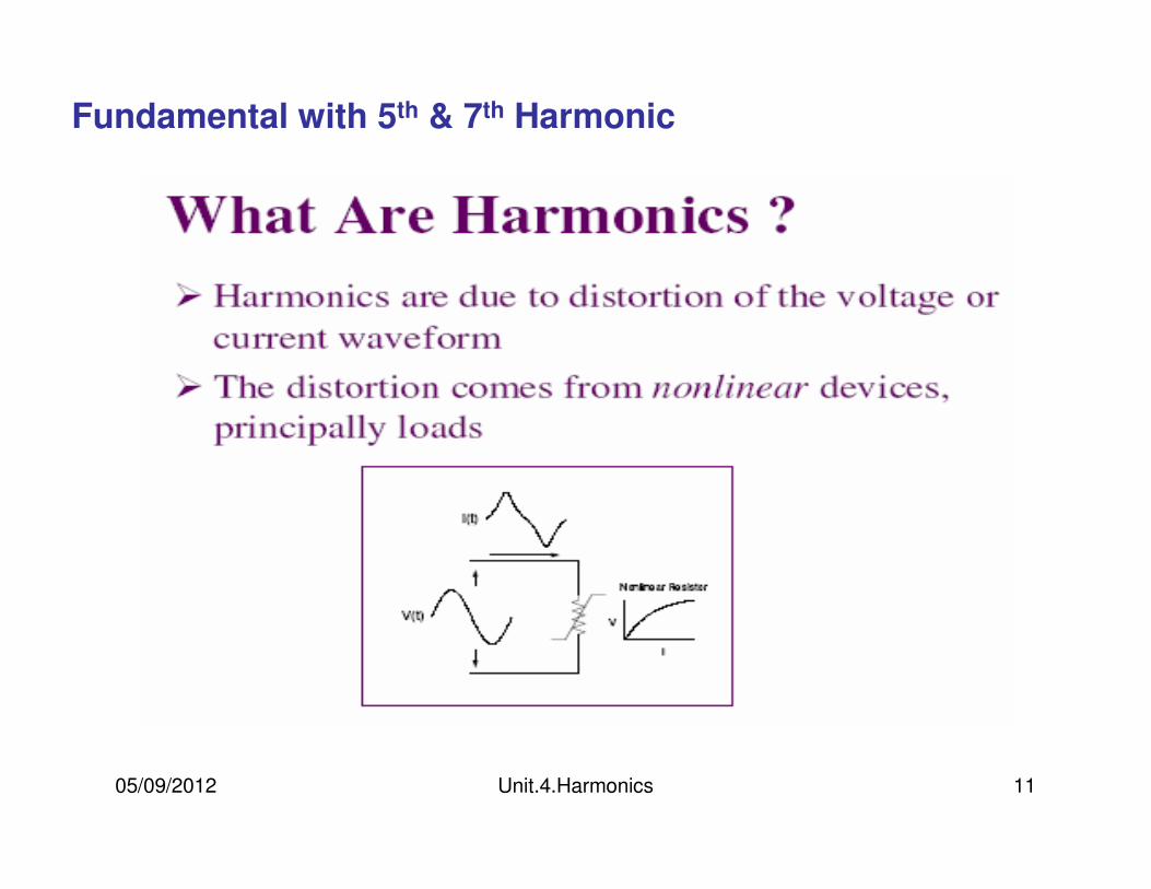
• Harmonic distortion: Voltage and current distortion
• Harmonic indices
• Harmonic sources from commercial and industrial loads
• Effects of harmonics on various equipments
• Harmonic distortion evaluation
• Devices for controlling harmonic distortion.
05/09/2012 Unit.4.Harmonics 3
05/09/2012 Unit.4.Harmonics 4
05/09/2012 Unit.4.Harmonics 5
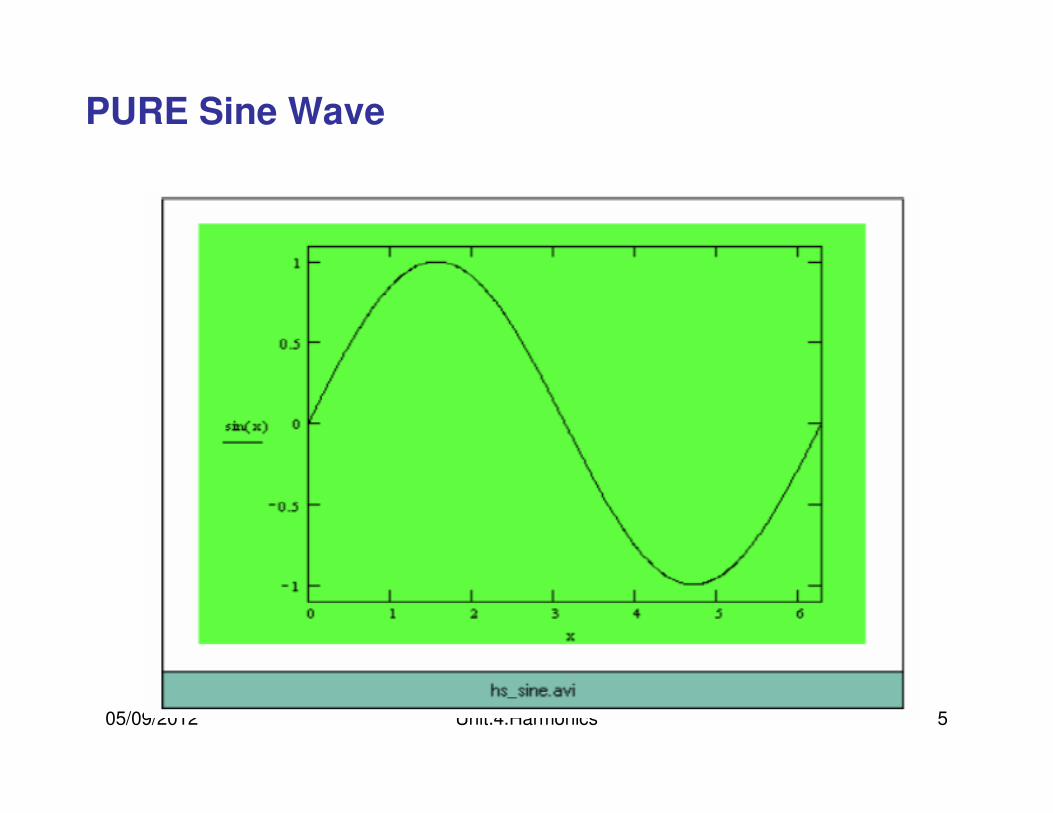
PURE Sine Wave
05/09/2012 Unit.4.Harmonics 6
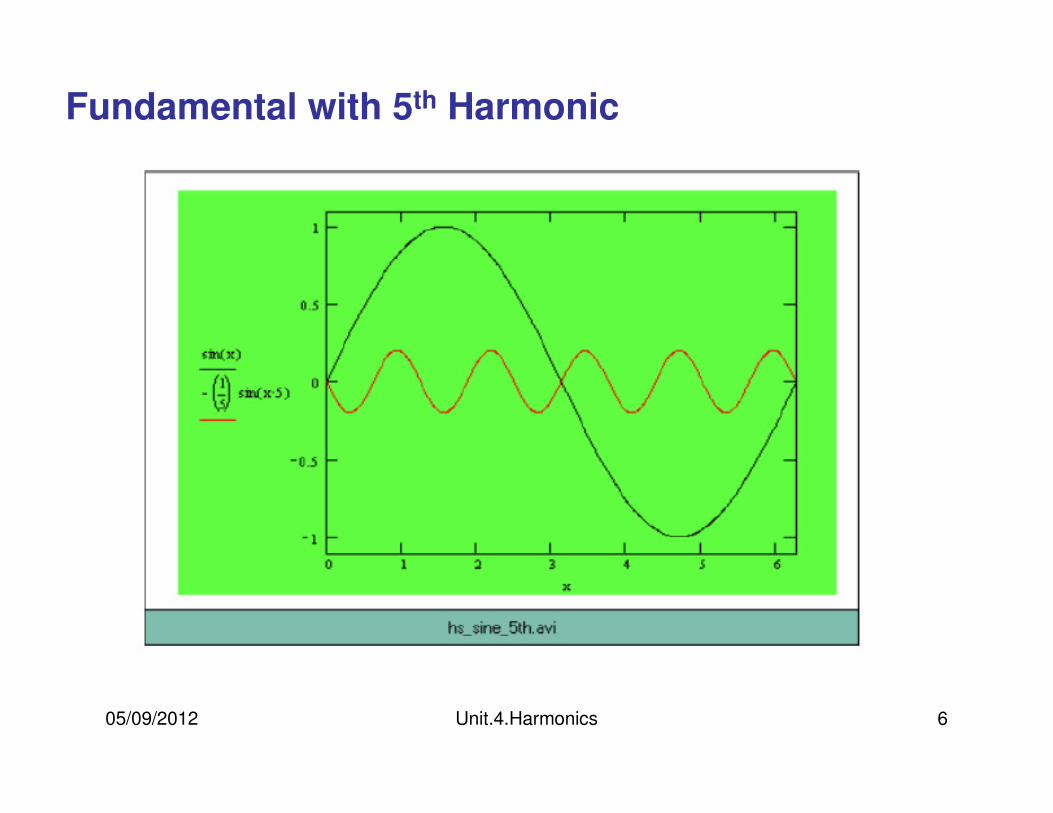
Fundamental with 5th Harmonic
05/09/2012 Unit.4.Harmonics 7
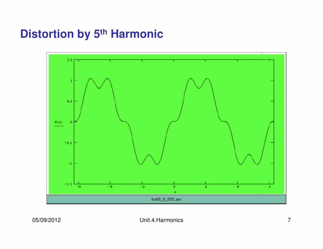
Distortion by 5th Harmonic
05/09/2012 Unit.4.Harmonics 8
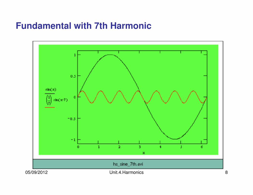
Fundamental with 7th Harmonic
05/09/2012 Unit.4.Harmonics 9
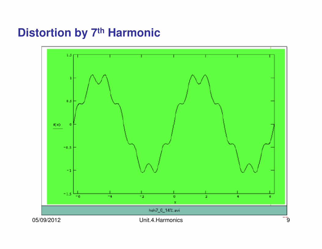
Distortion by 7th Harmonic
05/09/2012 Unit.4.Harmonics 10
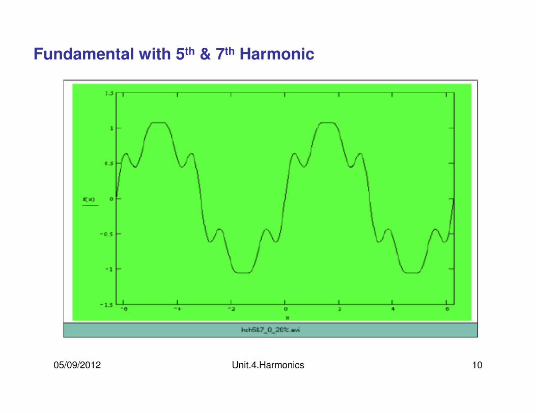
Fundamental with 5th & 7th Harmonic
05/09/2012 Unit.4.Harmonics 11
Fundamental with 5th & 7th Harmonic
05/09/2012 Unit.4.Harmonics 12
05/09/2012 Unit.4.Harmonics 13
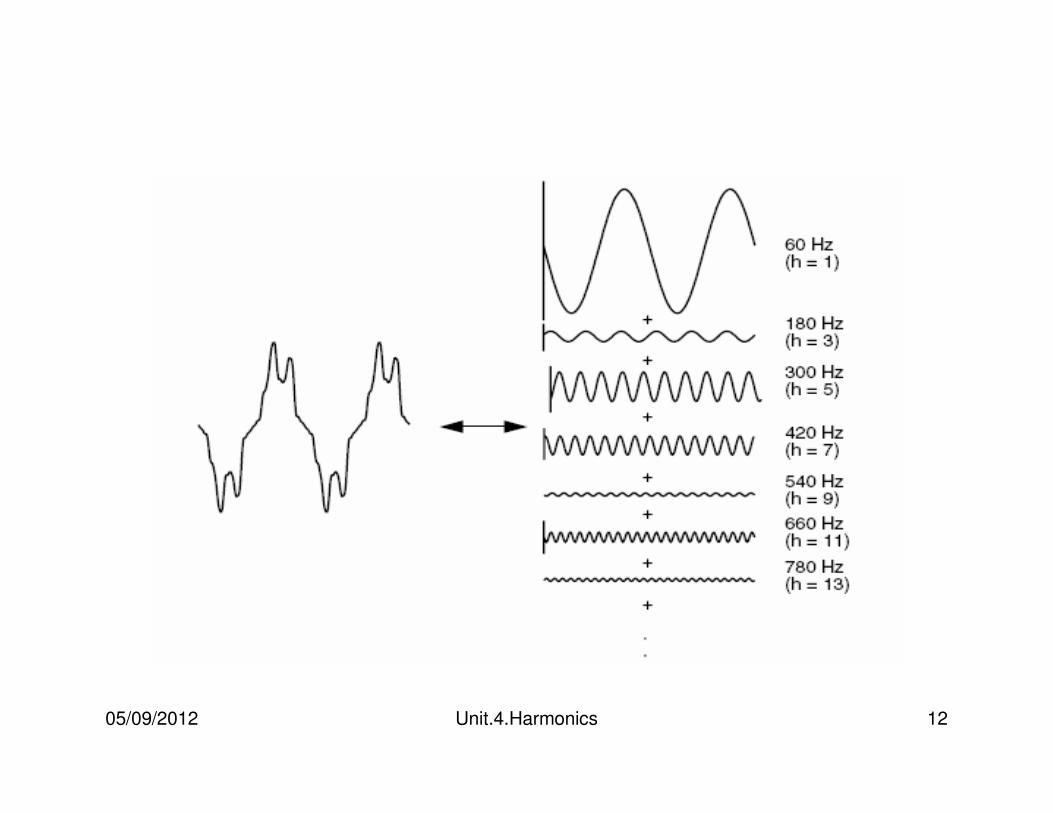
•Any periodic sinusoids can be expressed as sum of sinusoids
•When a waveform is identical from one cycle to the next, it can be represented as a sum of pure sine waves in which the frequency of each sinusoid is an integer multiple of the fundamental frequency of the distorted wave
•Harmonics is the integer multiple of fundamental component
05/09/2012 Unit.4.Harmonics 14
•When both the positive and negative half cycles of a waveform have identical shapes, the Fourier series contains only odd harmonics
•In fact, the presence of even harmonics is often a clue that there is something wrong—either with the load equipment or with the transducer used to make the measurement. There are notable exceptions to this such as half-wave rectifiers and arc furnaces when the arc is random.
05/09/2012 Unit.4.Harmonics 15
Linear vs. Non-linear loads and current waveforms
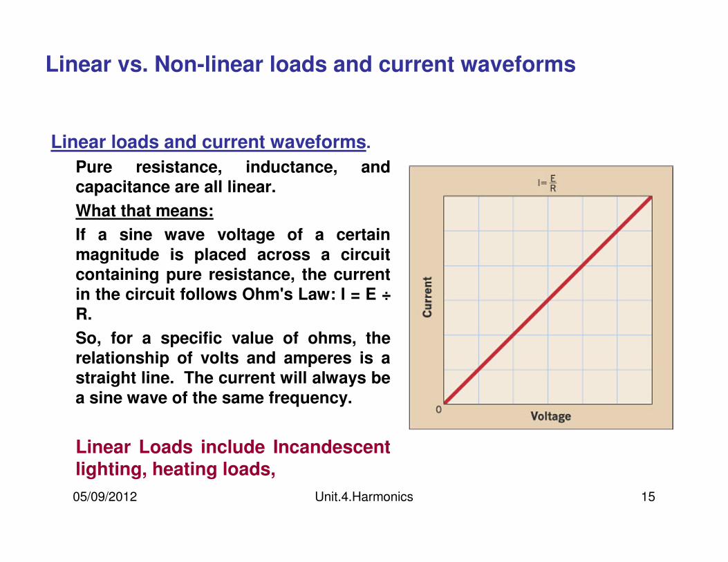
Linear loads and current waveforms.
Pure resistance, inductance, and capacitance are all linear.
What that means:
If a sine wave voltage of a certain
magnitude is placed across a circuit
containing pure resistance, the current
in the circuit follows Ohm's Law: I = E ÷R.
So, for a specific value of ohms, the
relationship of volts and amperes is a straight line. The current will always be
a sine wave of the same frequency.
Linear Loads include Incandescent lighting, heating loads,
05/09/2012 Unit.4.Harmonics 16
Linear vs. Non-linear loads and current waveforms
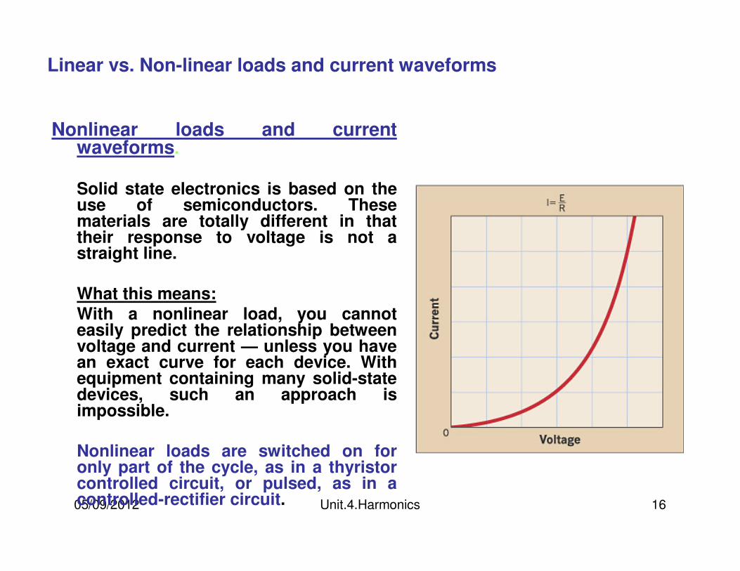
Nonlinear loads and current waveforms.
Solid state electronics is based on the use of semiconductors. These materials are totally different in that their response to voltage is not a straight line.
What this means:With a nonlinear load, you cannot easily predict the relationship between voltage and current — unless you have an exact curve for each device. With equipment containing many solid-state devices, such an approach is impossible.
Nonlinear loads are switched on for only part of the cycle, as in a thyristorcontrolled circuit, or pulsed, as in a controlled-rectifier circuit.
05/09/2012 Unit.4.Harmonics 17
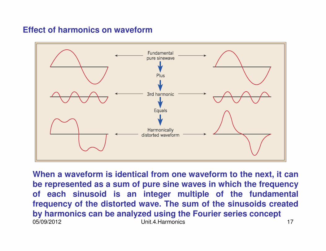
Effect of harmonics on waveform
When a waveform is identical from one waveform to the next, it can be represented as a sum of pure sine waves in which the frequency of each sinusoid is an integer multiple of the fundamental frequency of the distorted wave. The sum of the sinusoids created by harmonics can be analyzed using the Fourier series concept
05/09/2012 Unit.4.Harmonics 18
What do harmonics do?
• Harmonics are carried through the system from the source and can nearly double the amount of current on the neutral conductor in three phase four wire distribution systems.
• Distorted currents from harmonic-producing loads also distort the voltage as they pass through the system impedance. Therefore, a distorted voltage can be presented to other end users on the system.
• Overall electrical system and power quality is affected by the introduction of harmonics.
05/09/2012 Unit.4.Harmonics 19
Sources of Harmonics
• Solid State Electronic Devices which contain a poor power supply
–Computers (PCs/CPUs)
–Laser Printers
–Copy Machines
• Solid State UPS Units
• Solid State Devices (Fluorescent lighting ballasts)
• Rectifiers
• Welding Units
• Arc Furnaces
05/09/2012 Unit.4.Harmonics 20
Voltage vs. Current Distortion
The harmonic voltages are too great (the voltage too distorted) for the control to properly determine firing angles
The harmonic currents are too great for the capacity of some device in the power supply system such as a transformer, and the machine must be operated at a lower than rated power
05/09/2012 Unit.4.Harmonics 21
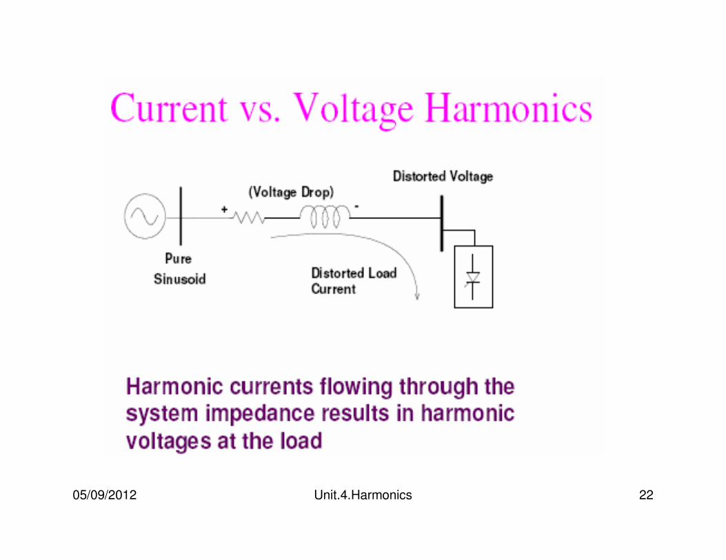
Voltage vs. Current Distortion
The harmonic voltages are too great because the harmonic currents produced by the device are too great for the given system condition
Nonlinear loads appear to be sources of harmonic current in shunt with and injecting harmonic currents into the power system
For nearly all analyses, it is sufficient to treat these harmonic producing loads simply as current sources
05/09/2012 Unit.4.Harmonics 22
05/09/2012 Unit.4.Harmonics 23
Voltage vs. Current Distortion
The harmonic currents passing through the impedance of the system cause a voltage drop for each harmonic. This results in voltage harmonics appearing at the load bus
The amount of voltage distortion depends on the impedance and the current. Assuming the load bus distortion stays within reasonable limits (e.g., less than 5 percent), the amount of harmonic current produced by the load is generally constant.
05/09/2012 Unit.4.Harmonics 24
Voltage vs. Current Distortion
While the load current harmonics ultimately cause the voltage distortion, it should be noted that load has no control over the voltage distortion. The same load put in two different locations on the power system will result in two different voltage distortion values.
Recognition of this fact is the basis for the division of responsibilities for harmonic control that are found in standards such as IEEE Standard 519-1992, Recommended Practices and Requirements for Harmonic Control in Electrical Power Systems:
05/09/2012 Unit.4.Harmonics 2525
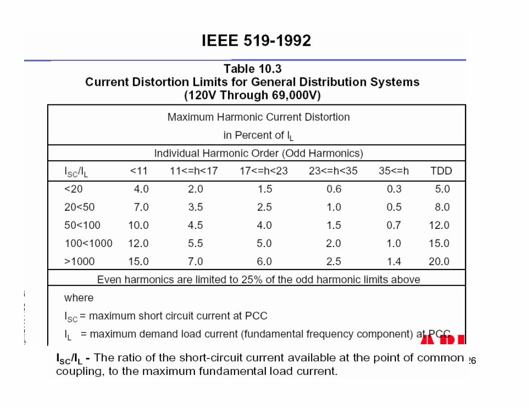
IEEE 519-1992
IEEE-519:1992 Recommended Practices and Requirements for Harmonic Control in Electrical Power Systems:
Specifies load current harmonic limits at PCC
Specifies supply voltage harmonic limits at PCC
05/09/2012 Unit.4.Harmonics 26
05/09/2012 Unit.4.Harmonics 27
Voltage vs. Current Distortion
The control over the amount of harmonic current injected into the system takes place at the end-use application
Assuming the harmonic current injection is within reasonable limits, the control over the voltage distortion is exercised by the entity having control over the system impedance, which is often the utility.
05/09/2012 Unit.4.Harmonics 28
POWER SYSTEM QUANTITIES UNDER NON SINUSOIDAL CONDITIONS
Traditional power system quantities are defined for the fundamental frequency context in a pure sinusoidal condition
•RMS
•Power (reactive, active, apparent)
•Power factor
•Phase sequences
05/09/2012 Unit.4.Harmonics 29
In the presence of harmonic distortion the power system no longer operates in a sinusoidal condition
Unfortunately many of the simplifications power engineers use for the fundamental frequency analysis do not apply.
05/09/2012 Unit.4.Harmonics 30
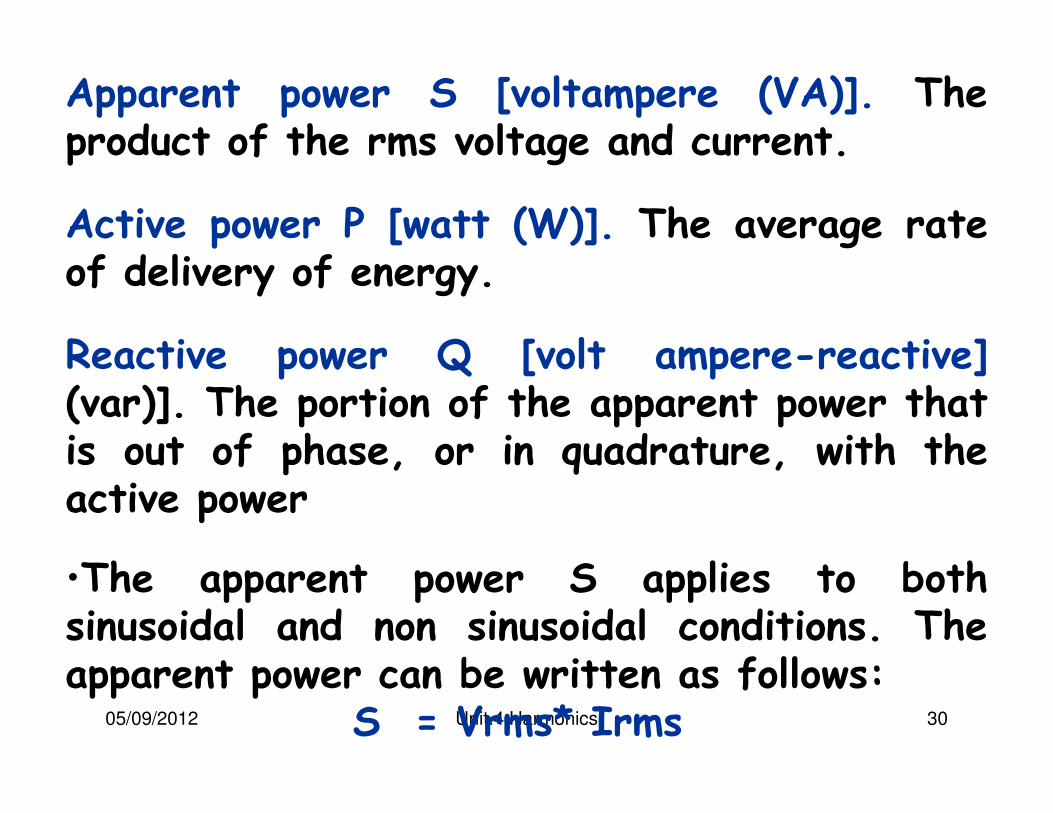
Apparent power S [voltampere (VA)]. The product of the rms voltage and current.
Active power P [watt (W)]. The average rate of delivery of energy.
Reactive power Q [volt ampere-reactive](var)]. The portion of the apparent power that is out of phase, or in quadrature, with the active power
•The apparent power S applies to both sinusoidal and non sinusoidal conditions. The apparent power can be written as follows:
S = Vrms* Irms
05/09/2012 Unit.4.Harmonics 31
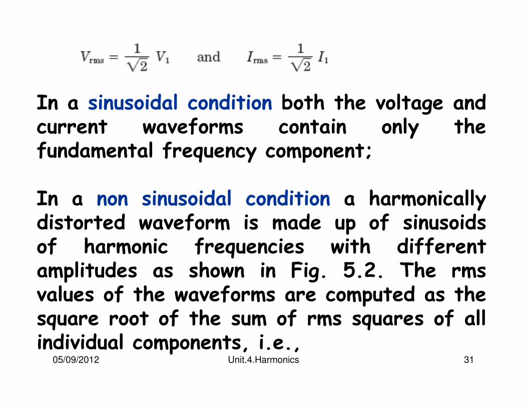
In a sinusoidal condition both the voltage and current waveforms contain only the fundamental frequency component;
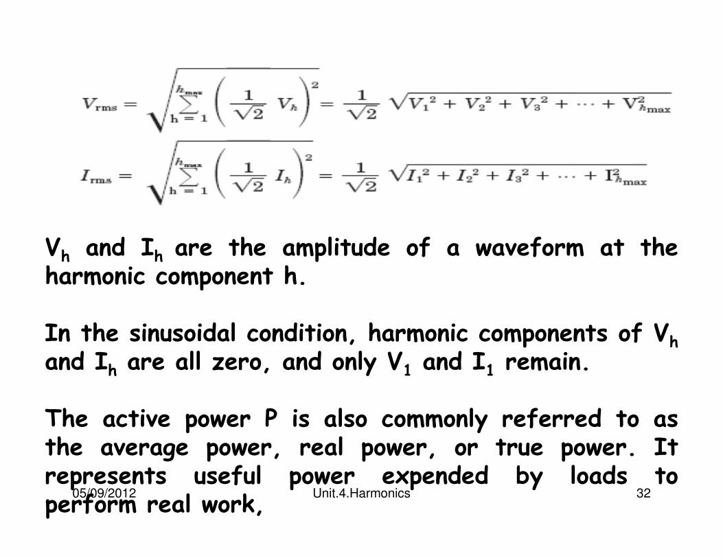
In a non sinusoidal condition a harmonically distorted waveform is made up of sinusoids of harmonic frequencies with different amplitudes as shown in Fig. 5.2. The rmsvalues of the waveforms are computed as the square root of the sum of rms squares of all individual components, i.e.,
05/09/2012 Unit.4.Harmonics 32
Vh and Ih are the amplitude of a waveform at the harmonic component h.
In the sinusoidal condition, harmonic components of Vh
and Ih are all zero, and only V1 and I1 remain.
The active power P is also commonly referred to as the average power, real power, or true power. It represents useful power expended by loads to perform real work,
05/09/2012 Unit.4.Harmonics 33
In electric power, real work is performed for the portion of the current that is in phase with the voltage.
No real work will result from the portion where the current is not in phase with the voltage.
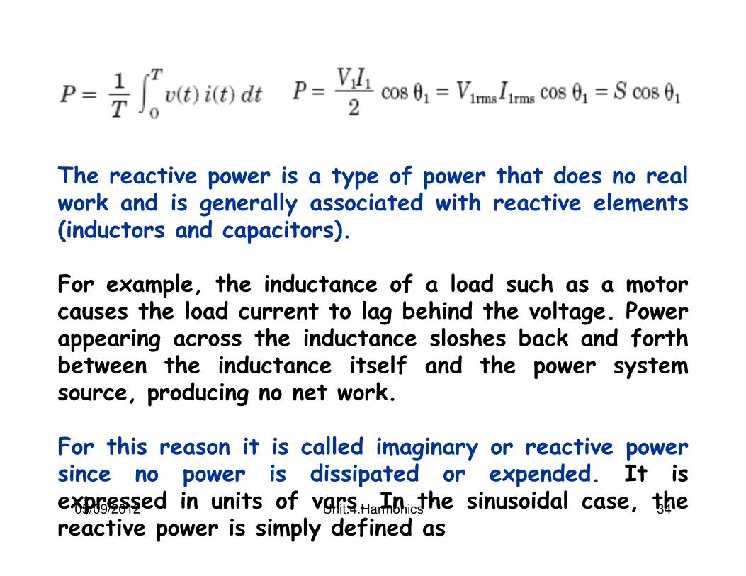
The active power is the rate at which energy is expended, dissipated, or consumed by the load and is measured in units of watts. P can be computed by averaging the product of the instantaneous voltage and current
05/09/2012 Unit.4.Harmonics 34
The reactive power is a type of power that does no real work and is generally associated with reactive elements (inductors and capacitors).
For example, the inductance of a load such as a motor causes the load current to lag behind the voltage. Power appearing across the inductance sloshes back and forth between the inductance itself and the power system source, producing no net work.
For this reason it is called imaginary or reactive power since no power is dissipated or expended. It is expressed in units of vars. In the sinusoidal case, the reactive power is simply defined as
05/09/2012 Unit.4.Harmonics 35
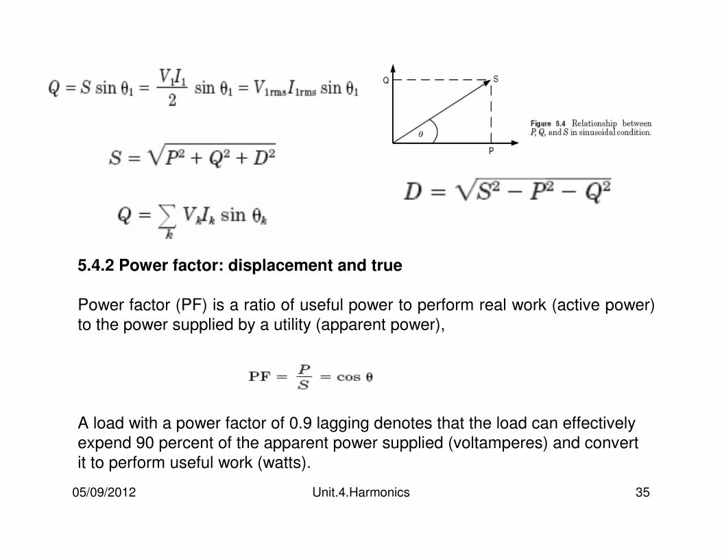
5.4.2 Power factor: displacement and true
Power factor (PF) is a ratio of useful power to perform real work (active power)
to the power supplied by a utility (apparent power),
A load with a power factor of 0.9 lagging denotes that the load can effectively
expend 90 percent of the apparent power supplied (voltamperes) and convert
it to perform useful work (watts).
05/09/2012 Unit.4.Harmonics 36
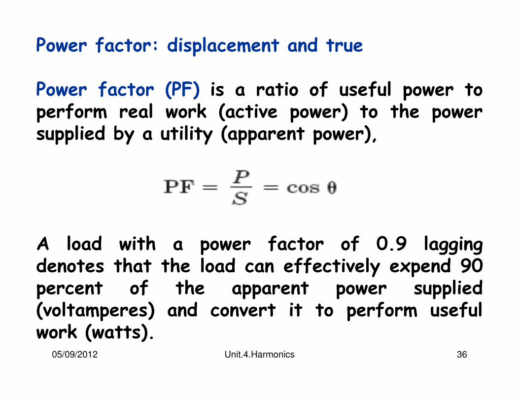
Power factor: displacement and true
Power factor (PF) is a ratio of useful power to perform real work (active power) to the power supplied by a utility (apparent power),
A load with a power factor of 0.9 lagging denotes that the load can effectively expend 90 percent of the apparent power supplied (voltamperes) and convert it to perform useful work (watts).
05/09/2012 Unit.4.Harmonics 37
Power factor can be computed as the cosine of the phase angle and is commonly referred as the displacement power factor:
The power factor that takes into account the contribution from all active power, including both fundamental and harmonic frequencies, is known as the true power factor.
The true power factor is simply the ratio of total active power for all frequencies to the apparent power delivered by the utility. In non-sinusoidal case,
05/09/2012 Unit.4.Harmonics 38
Power quality monitoring instruments now commonly report both displacement and true power factors.
Many devices such as switch-mode power supplies and PWM adjustable-speed drives have a near unity displacement power factor, but the true power factor may be 0.5 to 0.6.
An ac-side capacitor will do little to improve the true power factor.
05/09/2012 Unit.4.Harmonics 39
The true power factor indicates how large the power delivery system must be built to supply a given load.
The bottom line is that distortion results in additional current components flowing in the system that do not yield any net energyexcept that they cause losses in the power system elements they pass through.
This requires the system to be built to a slightly larger capacity to deliver the power to the load than if no distortion were present.
05/09/2012 Unit.4.Harmonics 40
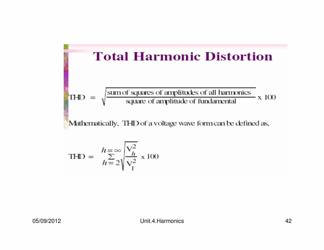
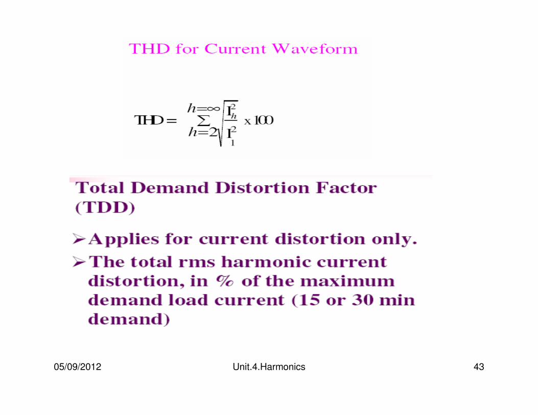
HARMONIC INDICES
1.THD
2.TDD
05/09/2012 Unit.4.Harmonics 41
05/09/2012 Unit.4.Harmonics 42
05/09/2012 Unit.4.Harmonics 43
05/09/2012 Unit.4.Harmonics 44
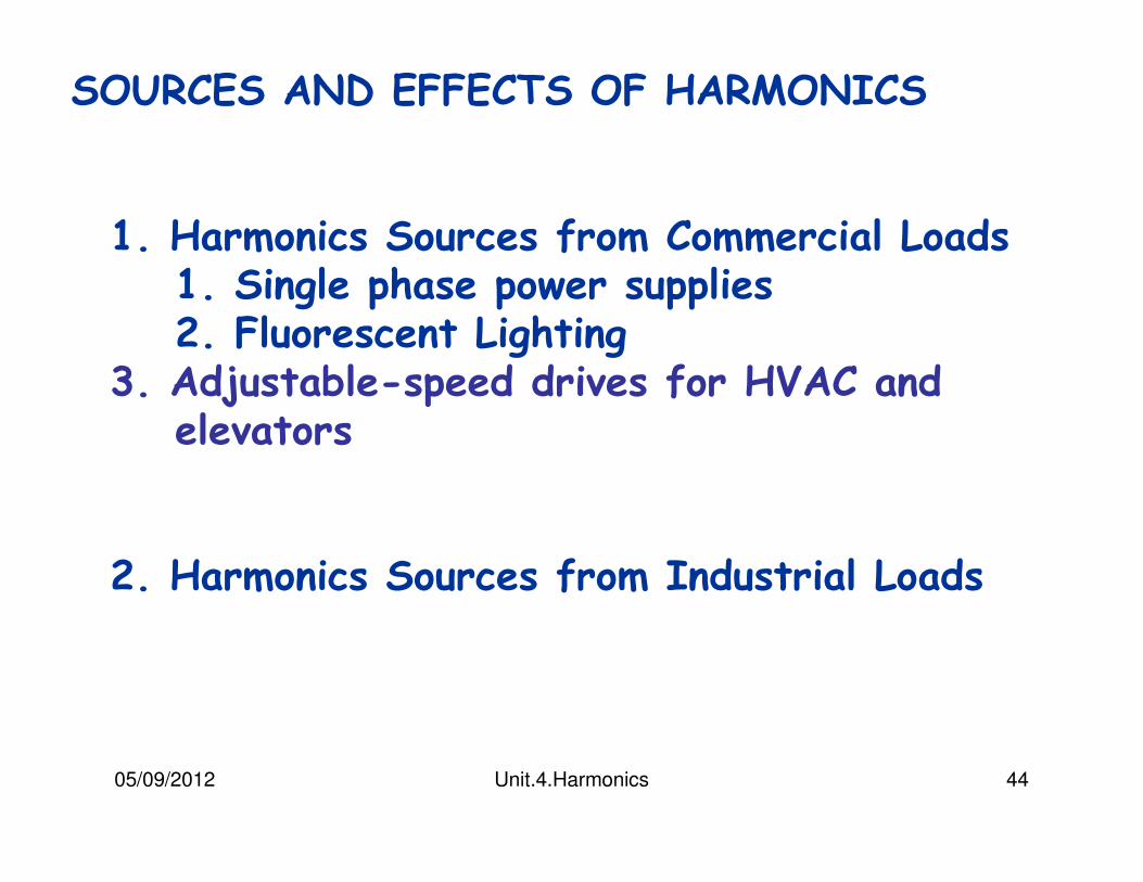
SOURCES AND EFFECTS OF HARMONICS
1. Harmonics Sources from Commercial Loads1. Single phase power supplies2. Fluorescent Lighting
3. Adjustable-speed drives for HVAC and elevators
2. Harmonics Sources from Industrial Loads
05/09/2012 Unit.4.Harmonics 45
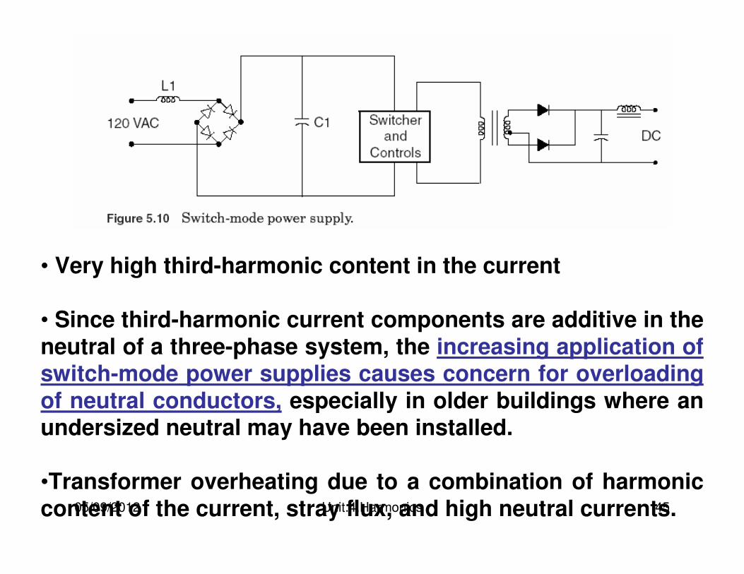
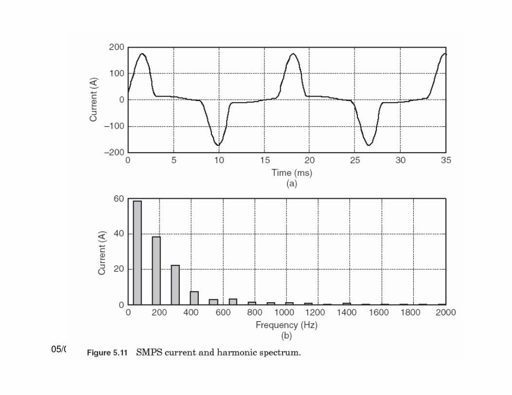
• Very high third-harmonic content in the current
• Since third-harmonic current components are additive in the neutral of a three-phase system, the increasing application of switch-mode power supplies causes concern for overloading
of neutral conductors, especially in older buildings where an undersized neutral may have been installed.
•Transformer overheating due to a combination of harmonic content of the current, stray flux, and high neutral currents.
05/09/2012 Unit.4.Harmonics 46
05/09/2012 Unit.4.Harmonics 47
Fluorescent lights are discharge lamps; thus they require a ballast to provide a high initial voltage to initiate the discharge for the electric current to flow between two electrodes in the fluorescent tube.
Once the discharge is established, the voltage decreases as the arc current increases. It is essentially a short circuit between the two electrodes, and the ballast has to quickly reduce the current to a level to maintain the specified lumen output. Thus, a ballast is also a current-limiting device in lighting applications. Two types of ballasts,
1.Magnetic Ballast2.Electronic Ballast
05/09/2012 Unit.4.Harmonics 48
A standard magnetic ballast is simply made up of an iron-core transformer with a capacitor encased in an insulating material.
A single magnetic ballast can drive one or two fluorescent lamps, and it operates at the line fundamental frequency, i.e., 50 or 60 Hz.
The iron-core magnetic ballast contributes additional heat losses, which makes it inefficient compared to an electronic ballast.
05/09/2012 Unit.4.Harmonics 49
05/09/2012 Unit.4.Harmonics 50
An electronic ballast employs a switch-mode–type power supply to convert the incoming fundamental frequency voltage to a much higher frequency voltage typically in the range of 25 to 40 kHz. This high frequency has two advantages.
1. A small inductor is sufficient to limit the arc current.
2. The high frequency eliminates or greatly reduces the 100- or 120-Hz flicker associated with an iron-core magnetic ballast.
A single electronic ballast typically can drive up to four fluorescent lamps.
05/09/2012 Unit.4.Harmonics 51
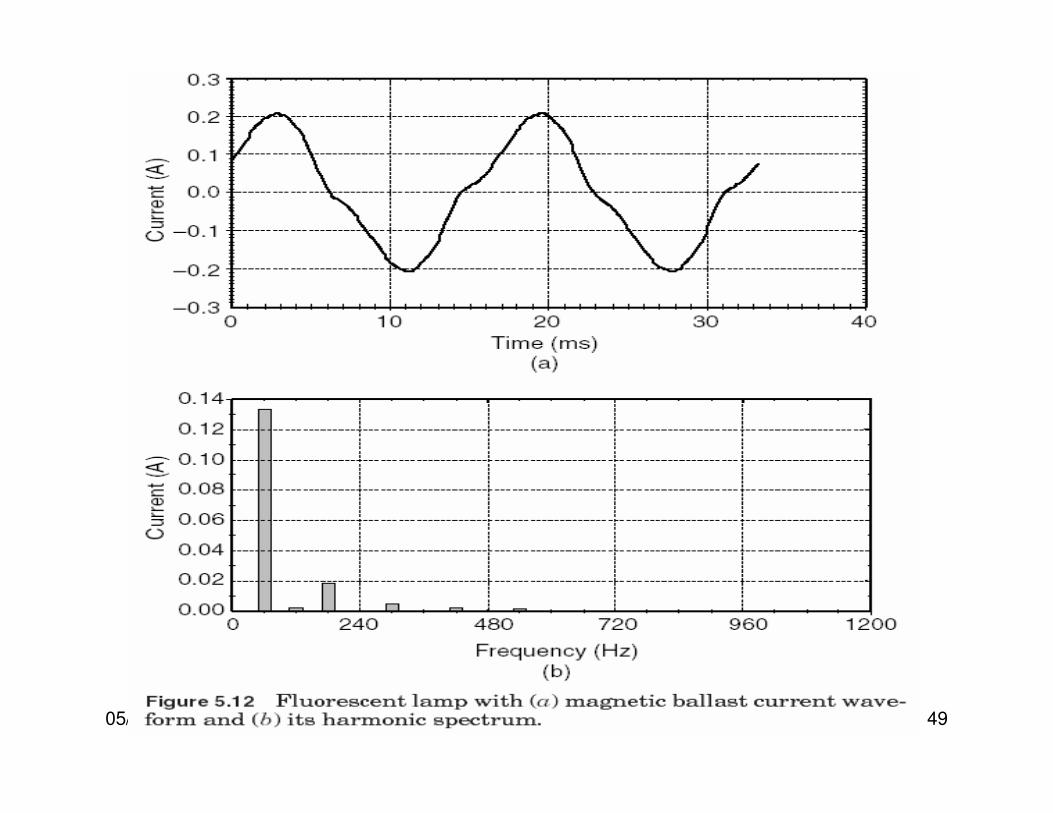
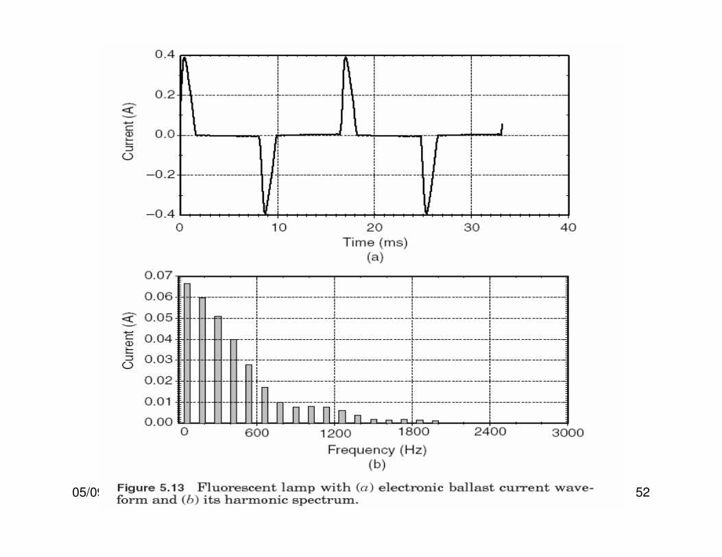
Figure 5.12 shows a measured fluorescent lamp current and harmonic spectrum. The current THD is a moderate 15 percent.
As a comparison, electronic ballasts, which employ switch-mode power supplies, can produce double or triple the standard magnetic ballast harmonic output.
Figure 5.13 shows a fluorescent lamp with an electronic ballast that has a current THD of 144.
05/09/2012 Unit.4.Harmonics 52
05/09/2012 Unit.4.Harmonics 53
ASDs for HVAC and Elevators
Common applications of ASDs in commercial loads can be found in elevator motors and in pumps and fans in HVAC systems.
ASD consists of an electronic power converter that converts ac voltage and frequency into variable voltage and frequency.
The variable voltage and frequency allows the ASD to control motor speed to match the application requirement such as slowing a pump or fan. ASDs also find many applications in industrial loads.
05/09/2012 Unit.4.Harmonics 54
Harmonic Sources from Industrial LoadsModern industrial facilities are characterized by the widespread application of nonlinear loads.
These loads can make up a significant portion of the total facility loads and inject harmonic currents into the power system, causing harmonic distortion in the voltage. Industrial facilities often utilize capacitor banks to improve the power factor to avoid penalty charges.
The application of power factor correction capacitors can potentially magnify harmonic currents from the nonlinear loads, giving rise to resonance conditions within the facility.
05/09/2012 Unit.4.Harmonics 55
Resonance conditions cause motor and transformer overheating, and misoperation of sensitive electronic equipment.
Nonlinear industrial loads can generally be grouped into three categories:
•Three-phase power converters
•Arcing devices
•Saturable devices
05/09/2012 Unit.4.Harmonics 56
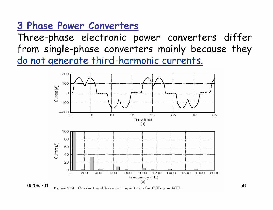
3 Phase Power ConvertersThree-phase electronic power converters differ from single-phase converters mainly because they do not generate third-harmonic currents.

05/09/2012 Unit.4.Harmonics 57
3 Phase Power ConvertersVoltage source inverter drives (such as PWM-type drives) can have much higher distortion levels as shown in Fig. 5.15.
05/09/2012 Unit.4.Harmonics 58
The input to the PWM drive is generally designed like a three-phase version of the switch-mode power supply in computers.
Whereas the switch-mode power supplies are generally for very small loads
PWM drives are now being applied for loads up to 500 horsepower (hp).
05/09/2012 Unit.4.Harmonics 59
DC Drives
Rectification is the only step required for dc drives. Therefore, they have the advantage of relatively simple control systems.
Compared with ac drive systems, the dc drive offers a wider speed range and higher starting torque.
Purchase and maintenance costs for dc motors are high, while the cost of power electronic devices has been dropping year after year.
05/09/2012 Unit.4.Harmonics 60
DC drives Contd..
Economic considerations limit use of the dc drive to applications that require the speed and torque characteristics of the dc motor.
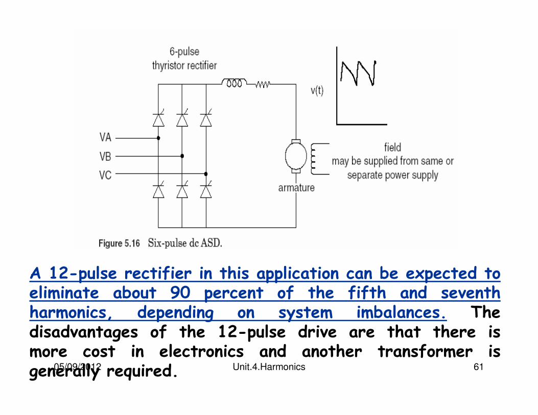
Most dc drives use the six-pulse rectifier shown in Fig. 5.16. Large drives may employ a 12-pulse rectifier. This reduces thyristor current duties and reduces some of the larger ac current harmonics.
Two largest harmonic currents for the six-pulse drive are the fifth and seventh.
05/09/2012 Unit.4.Harmonics 61
A 12-pulse rectifier in this application can be expected to eliminate about 90 percent of the fifth and seventh harmonics, depending on system imbalances. The disadvantages of the 12-pulse drive are that there is more cost in electronics and another transformer is generally required.
05/09/2012 Unit.4.Harmonics 62
AC Drives
In ac drives, the rectifier output is inverted to produce a variable-frequency ac voltage for the motor.
Inverters are classified as voltage source inverters (VSIs) or current source inverters (CSIs).
A VSI requires a constant dc (i.e., low-ripple) voltage input to the inverter stage. This is achieved with a capacitor or LC filter in the dc link.
The CSI requires a constant current input; hence, a series inductor is placed in the dc link.
05/09/2012 Unit.4.Harmonics 63
AC Drives contd…
AC drives generally use standard squirrel cage induction motors. These motors are rugged, relatively low in cost, and require little maintenance.
Synchronous motors are used where precise speed control is critical.
A popular ac drive configuration uses a VSI employing PWM techniques to synthesize an ac waveform as a train of variable-width dc pulses (see Fig. 5.17).
05/09/2012 Unit.4.Harmonics 64
AC Drives contd…
Another advantage of PWM drives is that, unlike other types of drives, it is not necessary to vary rectifier output voltage to control motor speed.
This allows the rectifier thyristors to be replaced with diodes, and the thyristor control circuitry to be eliminated.
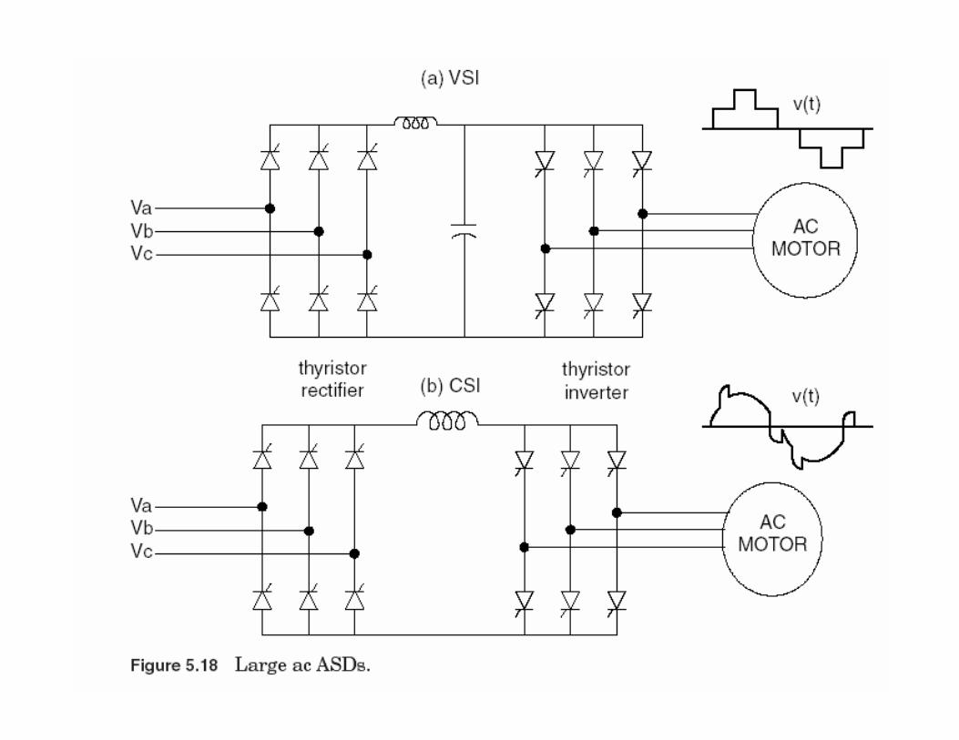
VSI drives (Fig. 5.18a) are limited to applications that do not require rapid changes in speed.
05/09/2012 Unit.4.Harmonics 65
AC Drives contd…
CSI drives (Fig. 5.18b) have good acceleration/deceleration characteristics but require a motor with a leading power factor (synchronous or induction with capacitors) or added control circuitry to commutate the inverter thyristors. In either case, the CSI drive must be designed for use with a specific motor.
Thyristors in CSI must be protected against inductive voltage spikes, which increases the cost of this type of drive.
05/09/2012 Unit.4.Harmonics 66
05/09/2012 Unit.4.Harmonics 67
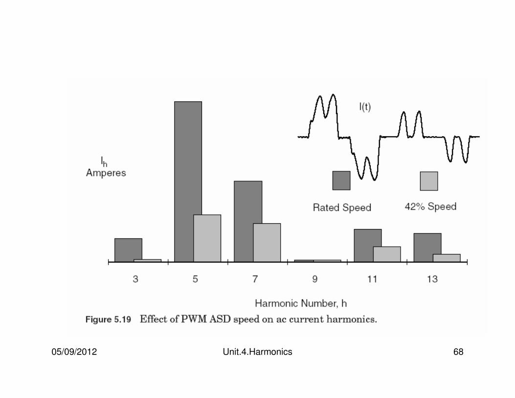
Impact of operating condition
The harmonic current distortion in adjustable-speed drives is not constant. The waveform changes significantly for different speed and torque values.
While the waveform at 42 percent speed is much more distorted proportionately, the drive injects considerably higher magnitude harmonic currents at rated speed.
The bar chart shows the amount of current injected. This will be the limiting design factor, not the highest THD.
05/09/2012 Unit.4.Harmonics 68
05/09/2012 Unit.4.Harmonics 69
Arcing devices
1.Arc furnaces2.Arc welders3.Discharge-type lighting (fluorescent, sodium vapor, mercury vapor) with magnetic ballasts.
As shown in Fig. 5.20, the arc is basically a voltage clamp in series with a reactance that limits current to a reasonable value.
The voltage-current characteristics of electric arcs are nonlinear. Following arc ignition, the voltage decreases as the arc current increases, limited only by the impedance of the power system.
05/09/2012 Unit.4.Harmonics 70
The electric arc itself is actually best represented as a source of voltage harmonics.
The harmonic content of an arc furnace load and other arcing devices is similar to that of the magnetic ballast shown in Fig. 5.12.
Three phase arcing devices can be arranged to cancel the triplen harmonics through the transformer connection.
05/09/2012 Unit.4.Harmonics 71
Saturable devices
1.Transformers
2.Electromagnetic devices with a steel core, including motors.
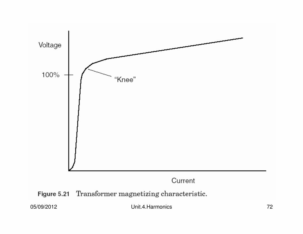
Harmonics are generated due to the nonlinear magnetizing characteristics of the steel (see Fig. 5.21).
Power transformers are designed to normally operate just below the “knee” point of the magnetizing saturation characteristic.
05/09/2012 Unit.4.Harmonics 72
05/09/2012 Unit.4.Harmonics 73
Saturable devices
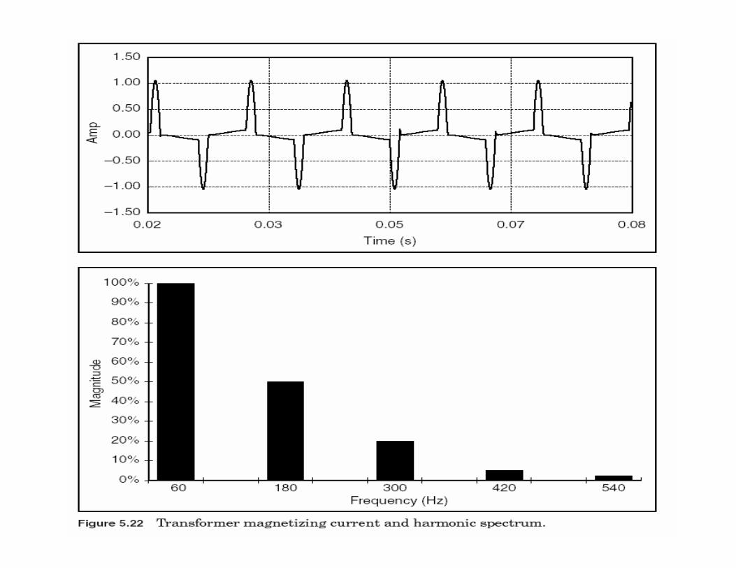
Although transformer exciting current is rich in harmonics at normal operating voltage (see Fig. 5.22), it is typically less than 1 percent of rated full load current.
Transformers are not as much of a concern as electronic power converters and arcing devices which can produce harmonic currents of 20 percent of their rating, or higher. However, their effect will be noticeable, particularly on utility distribution systems, which have hundreds of transformers.
05/09/2012 Unit.4.Harmonics 74
Saturable devices
The waveform shown in Fig. 5.22 is for single-phase or wye-grounded three-phase transformers.
The current obviously contains a large amount of third harmonic.
Delta connections and ungrounded-wye connections prevent the flow of zero-sequence harmonic, which triplens tend to be.
05/09/2012 Unit.4.Harmonics 75
05/09/2012 Unit.4.Harmonics 76
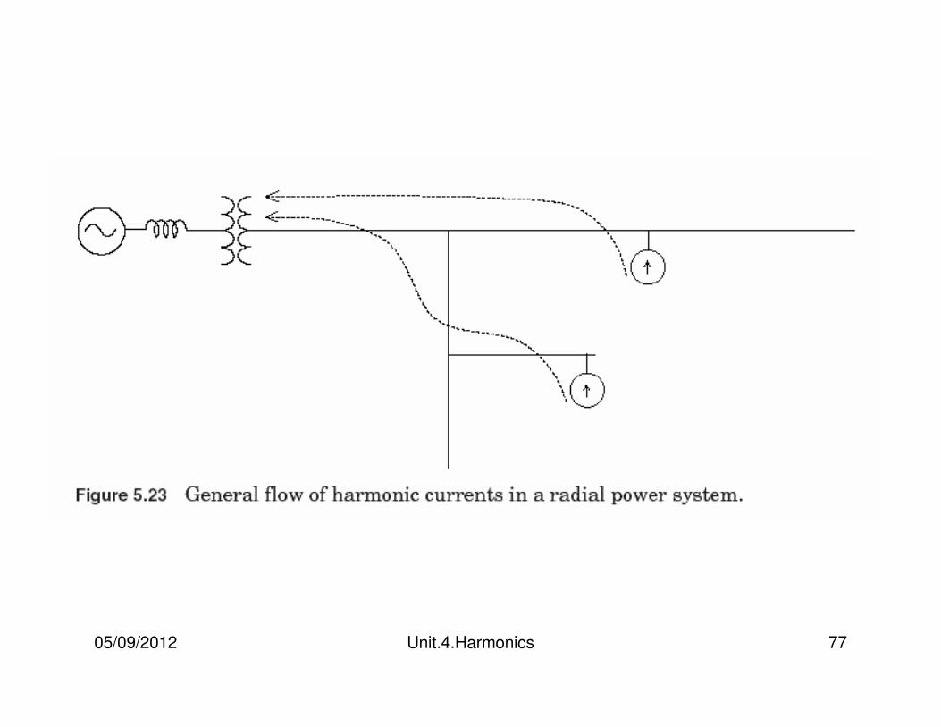
Locating Harmonic Sources
On radial utility distribution feeders and industrial plant power systems, the main tendency is for the harmonic currents to flow from the harmonic-producing load to the power system source.
This is illustrated in Fig. 5.23. The impedance of the power system is normally the lowest impedance seen by the harmonic currents. Thus, the bulk of the current flows into the source.
05/09/2012 Unit.4.Harmonics 77
05/09/2012 Unit.4.Harmonics 78
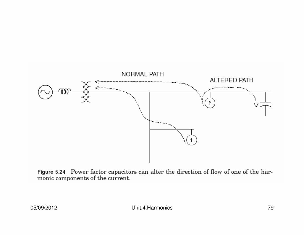
Locating Harmonic Sources contd…
Power factor correction capacitors can alter this flow pattern for at least one of the harmonics.
For example, adding a capacitor to the previous circuit as shown in Fig. 5.24 may draw a large amount of harmonic current into that portion of the circuit.
In such a situation, following the path of the harmonic current will lead to a capacitor bank instead of the actual harmonic source. Thus, it is generally necessary to temporarily disconnect all capacitors to reliably locate the sources of harmonics.
05/09/2012 Unit.4.Harmonics 79
05/09/2012 Unit.4.Harmonics 80
System Response Characteristics
In power systems, the response of the system is equally as important as the sources of harmonics.
In fact, power systems are quite tolerant of the currents injected by harmonic-producing loads unless there is some adverse interaction with the impedance of the system.
Identifying the sources is only half the job of harmonic analysis.
The response of the power system at each harmonic frequency determines the true impact of the nonlinear load on harmonic voltage distortion.
05/09/2012 Unit.4.Harmonics 81
System Response Characteristics
There are three primary variables affecting the system response characteristics, i.e.,
1. System impedance
2. Presence of a capacitor bank
3. Amount of resistive loads in the system
05/09/2012 Unit.4.Harmonics 82
1. System impedance
At the fundamental frequency, power systems are primarily inductive, and the equivalent impedance is sometimes called simply the short-circuit reactance.
Capacitive effects are frequently neglected on utility distribution systems and industrial power systems.
Most frequently used quantities in the analysis of harmonics on power systems is the short-circuit impedance to the point on a network at which a capacitor is located.
05/09/2012 Unit.4.Harmonics 83
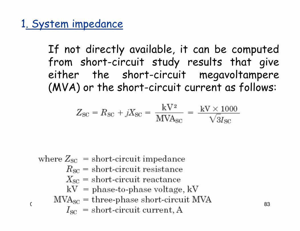
1. System impedance
If not directly available, it can be computed from short-circuit study results that give either the short-circuit megavoltampere (MVA) or the short-circuit current as follows:
05/09/2012 Unit.4.Harmonics 84

05/09/2012 Unit.4.Harmonics 85
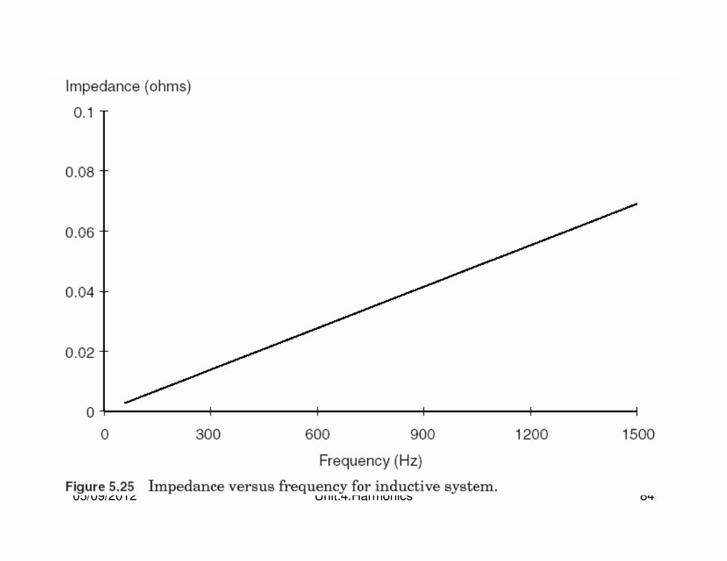
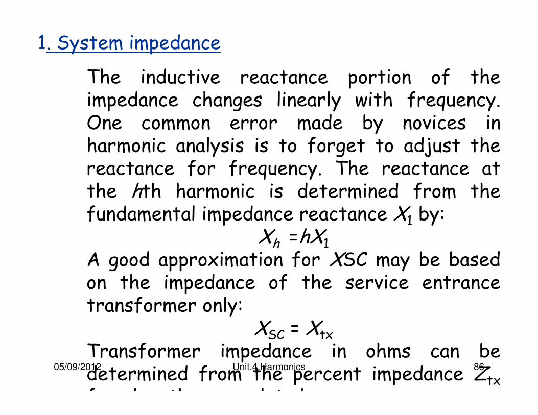
1. System impedance
The inductive reactance portion of the impedance changes linearly with frequency. One common error made by novices in harmonic analysis is to forget to adjust the reactance for frequency. The reactance at the hth harmonic is determined from the fundamental impedance reactance X1 by:
Xh =hX1
A good approximation for XSC may be based on the impedance of the service entrance transformer only:
XSC = Xtx
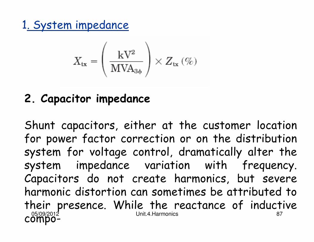
Transformer impedance in ohms can be determined from the percent impedance Ztx
found on the nameplate by
05/09/2012 Unit.4.Harmonics 86
1. System impedance
The inductive reactance portion of the impedance changes linearly with frequency. One common error made by novices in harmonic analysis is to forget to adjust the reactance for frequency. The reactance at the hth harmonic is determined from the fundamental impedance reactance X1 by:
Xh =hX1
A good approximation for XSC may be based on the impedance of the service entrance transformer only:
XSC = Xtx
Transformer impedance in ohms can be determined from the percent impedance Ztx
found on the nameplate by
05/09/2012 Unit.4.Harmonics 87
1. System impedance
2. Capacitor impedance
Shunt capacitors, either at the customer location for power factor correction or on the distribution system for voltage control, dramatically alter the system impedance variation with frequency. Capacitors do not create harmonics, but severe harmonic distortion can sometimes be attributed to their presence. While the reactance of inductive compo-
05/09/2012 Unit.4.Harmonics 88
2. Capacitor impedance
Shunt capacitors, either at the customer location for power factor correction or on the distribution system for voltage control, dramatically alter the system impedance variation with frequency.
Capacitors do not create harmonics, but severe harmonic distortion can sometimes be attributed to their presence.
While the reactance of inductive components increases proportionately to frequency, capacitive reactance XC decreases proportionately: XC = 1/2ΠfC
05/09/2012 Unit.4.Harmonics 89
3. Parallel resonance
All circuits containing both capacitances and inductances have one or more natural frequencies.
When one of those frequencies lines up with a frequency that is being produced on the power system, a resonance may develop in which the voltage and current at that frequency continue to persist at very high values.
This is the root of most problems with harmonic distortion on power systems.
05/09/2012 Unit.4.Harmonics 90
05/09/2012 Unit.4.Harmonics 91
3. Parallel resonance
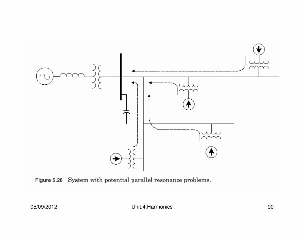
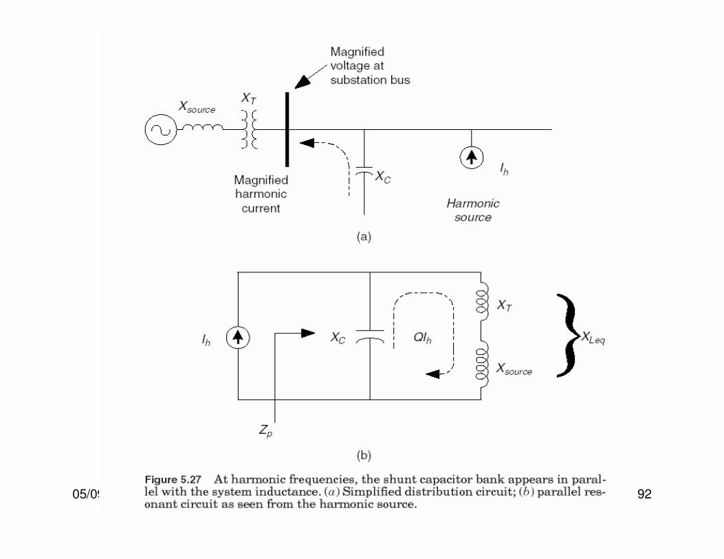
Figure 5.26 shows a distribution system with potential parallel resonance problems.
From the perspective of harmonic sources the shunt capacitor appears in parallel with the equivalent system inductance (source and transformer inductances) at harmonic frequencies as depicted in Fig. 5.27b.
Furthermore, since the power system is assumed to have an equivalent voltage source of fundamental frequency only, the power system voltage source appears short circuited in the figure.
05/09/2012 Unit.4.Harmonics 92
05/09/2012 Unit.4.Harmonics 93
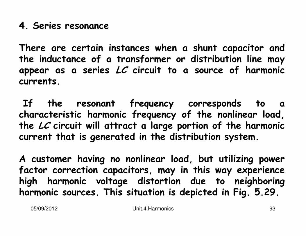
4. Series resonance
There are certain instances when a shunt capacitor and the inductance of a transformer or distribution line may appear as a series LC circuit to a source of harmonic currents.
If the resonant frequency corresponds to a characteristic harmonic frequency of the nonlinear load, the LC circuit will attract a large portion of the harmonic current that is generated in the distribution system.
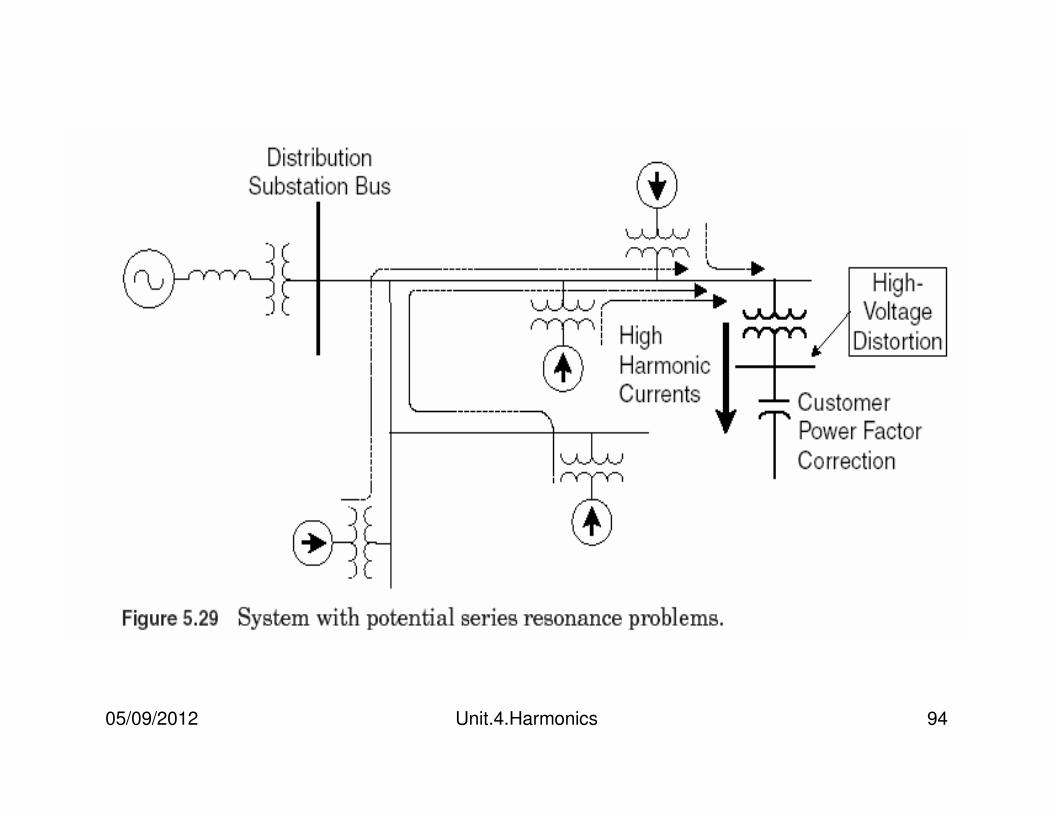
A customer having no nonlinear load, but utilizing power factor correction capacitors, may in this way experience high harmonic voltage distortion due to neighboring harmonic sources. This situation is depicted in Fig. 5.29.
05/09/2012 Unit.4.Harmonics 94
05/09/2012 Unit.4.Harmonics 95
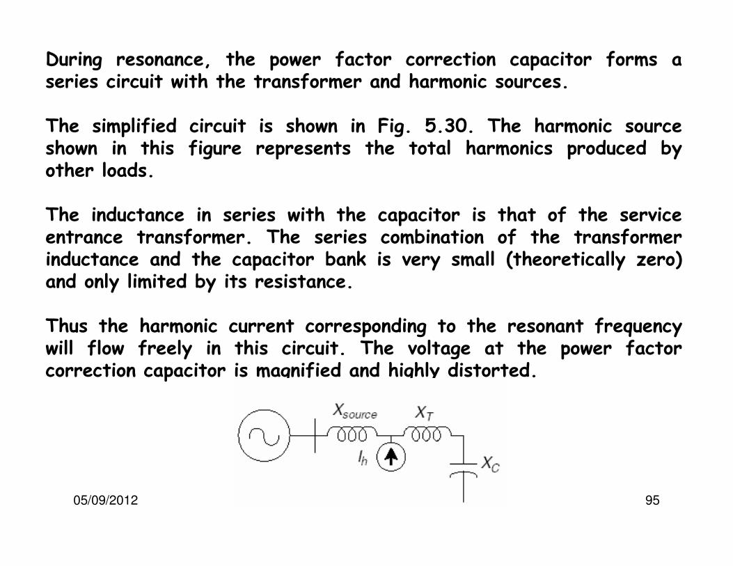
During resonance, the power factor correction capacitor forms a series circuit with the transformer and harmonic sources.
The simplified circuit is shown in Fig. 5.30. The harmonic source shown in this figure represents the total harmonics produced by other loads.
The inductance in series with the capacitor is that of the service entrance transformer. The series combination of the transformer inductance and the capacitor bank is very small (theoretically zero) and only limited by its resistance.
Thus the harmonic current corresponding to the resonant frequency will flow freely in this circuit. The voltage at the power factor correction capacitor is magnified and highly distorted.
05/09/2012 Unit.4.Harmonics 96
4. Effect of Resistive Load
It is a misconception that resistive loads damp harmonics because in the absence of resonance, loads of any kind will have little impact on the harmonic currents and resulting voltage distortion.
Most of the current will flow back into the power source. However, it is very appropriate to say that resistive loads will damp resonance, which will lead to a significant reduction in the harmonic distortion.
Motor loads are primarily inductive and provide little damping. In fact, they may increase distortion by shifting the system resonant frequency closer to a significant harmonic.
05/09/2012 Unit.4.Harmonics 97
Effects of Harmonic Distortion
Harmonic currents produced by nonlinear loads are injected back into the supply systems.
These currents can interact adversely with a wide range of power system equipment, most notably capacitors, transformers, and motors, causing additional losses, overheating, and overloading.
Harmonic currents can also cause interference with telecommunication lines and errors in power metering.
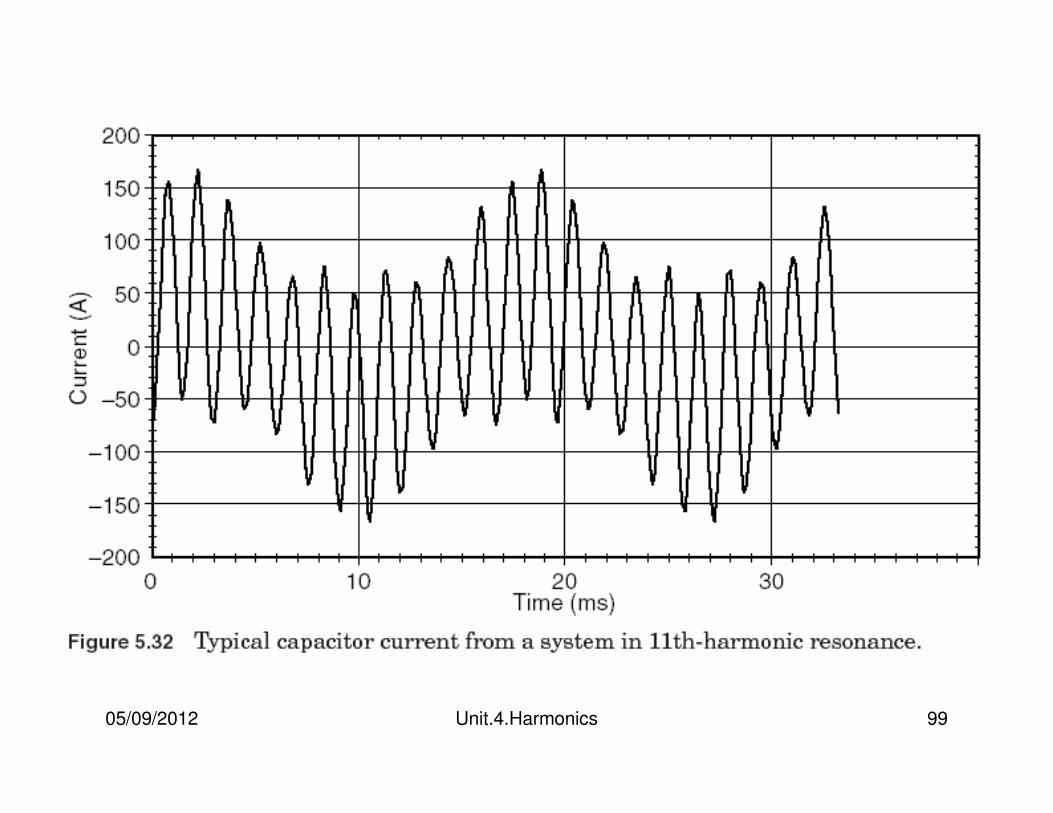
Impact on capacitors
Capacitor bank experiences high voltage distortion during resonance. The current flowing in the capacitor bank is also significantly large and rich in a monotonic harmonic.
05/09/2012 Unit.4.Harmonics 98
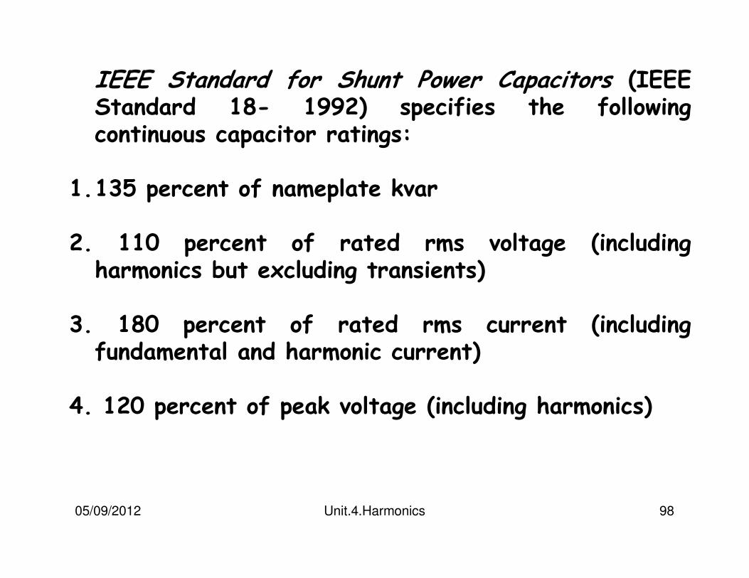
IEEE Standard for Shunt Power Capacitors (IEEE Standard 18- 1992) specifies the following continuous capacitor ratings:
1.135 percent of nameplate kvar
2. 110 percent of rated rms voltage (including harmonics but excluding transients)
3. 180 percent of rated rms current (including fundamental and harmonic current)
4. 120 percent of peak voltage (including harmonics)
05/09/2012 Unit.4.Harmonics 99
05/09/2012 Unit.4.Harmonics 100
Transformers are designed to deliver the required power to the connected loads with minimum losses at fundamental frequency.
Harmonic distortion of the current, in particular, as well as of the voltage will contribute significantly to additional heating.
To design a transformer to accommodate higher frequencies, designers make different design choices such as using continuously transposed cable instead of solid conductor and putting in more cooling ducts.
As a general rule, a transformer in which the current distortion exceeds 5 percent is a candidate for derating for harmonics.
05/09/2012 Unit.4.Harmonics 101
There are three effects that result in increased transformer heating when the load current includes harmonic components:
1. RMS current. If the transformer is sized only for the kVA requirements of the load, harmonic currents may result in the transformer rms current being higher than its capacity. The increased total rms current results in increased conductor losses.
2. Eddy current losses. These are induced currents in a transformer caused by the magnetic fluxes. These induced currents flow in the windings, in the core, and in other conducting bodies subjected to the magnetic field of the transformer and cause additional heating. This component of the transformer losses increases with the square of the frequency of the current causing the eddy currents. Therefore, this becomes a very important component of transformer losses for harmonic heating.
05/09/2012 Unit.4.Harmonics 102
3. Core losses.
The increase in core losses in the presence of harmonics will be dependent on the effect of the harmonics on the applied voltage and the design of the transformer core.
Increasing the voltage distortion may increase the eddy currents in the core laminations. The net impact that this will have depends on the thickness of the core laminations and the quality of the core steel. The increase in these losses due to harmonics is generally not as critical as the previous two.
05/09/2012 Unit.4.Harmonics 103
Impact on motors
Motors can be significantly impacted by the harmonic voltage distortion. Harmonic voltage distortion at the motor terminals is translated into harmonic fluxes within the motor.
Harmonic fluxes do not contribute significantly to motor torque, but rotate at a frequency different than the rotor synchronous frequency, basically inducing high-frequency currents in the rotor. The additional fluxes do little more than induce additional losses. Decreased efficiency along with heating, vibration, and high-pitched noises are indicators of harmonic voltage distortion.
05/09/2012 Unit.4.Harmonics 104
Impact on motors
There is usually no need to derate motors if the voltage distortion remains within IEEE Standard 519-1992 limits of 5 percent THD and 3 percent for any individual harmonic.
Excessive heating problems begin when the voltage distortion reaches 8 to 10 percent and higher.Such distortion should be corrected for long motor life.
05/09/2012 Unit.4.Harmonics 105
Impact on energy and demand metering
Electric utility companies usually measure energy consumption in two quantities: 1.Total cumulative energy consumed 2.Maximum power used for a given period.
Thus, there are two charges in any given billing period especially for larger industrial customers: energy chargesand demand charges.
Residential customers are typically charged for the energy consumption only.
Energy Charge represents the costs of producing and supplying the total energy consumed over a billing period and is measured in kilowatt-hours.
05/09/2012 Unit.4.Harmonics 106
Impact on energy and demand metering
The second part of the bill, the demand charge, represents utility costs to maintain adequate electrical capacity at all times to meet each customer’s peak demand for energy use. The demand charge reflects the utility’s fixed cost in providing peak power requirements.
The demand charge is usually determined by the highest 15- or 30-min peak demand of use in a billing period and is measured in kilowatts.
Both energy and demand charges are measured using the so-called watthour and demand meters.
05/09/2012 Unit.4.Harmonics 107
References
1. Electric Power System Quality – Roger C.Dugan,Mark F. McGranaghan, Mark McGranaghan, Surya Santoso, H. Wayne Beaty, H. Beaty, Tata McGraw-Hill Education.
2. Power Quality Primer - Barry kennedy