Embed Size (px)
Citation preview

Unit operation Dr. N. K. Patel
PRACTICAL: 1
PSYCHOMETRIC PROPERTIES
Aim: To study the psychometric properties using psychometric chart.
Requirement: Set of dry bulb thermometer and wet bulb thermometer.
Process:
Take two mercury thermometers. Suspend one in open air. It would give dry
bulb temperature. Cover the bulb of thermometer with the help of cotton cloth. Dip
the covered bulb in water. It would give wet bulb temperature. Note down the dry
bulb and wet bulb temperature. Find out required properties using chart.
Result:
1. Enthalpy at saturation = ____________
2. Relative humidity =_________________
3. Absolute humidity =________________
4. Humid volume = ___________________

Unit operation Dr. N. K. Patel
PRACTICAL: 2
JAW CRUSHER
Aim: Crush the given material in Jaw crusher and determine average particle size
and reduction ratio.
Requirement: Jaw crusher, Sieves of different mesh no. , Mechanical sieve shaker,
weighing balance, weight box etc.
Theory:
Crushers are the slow speed machine for course reduction of large quantities
of solids. Jaw crusher operated by compression and can break large lumps of very
hard materials like ores, rocks etc. It is a primary crusher.
In jaw crusher feed is adjusted between two jaws, set to form V open at the
top. One jaw is fixed and nearly vertical and does not move .The other swinging jaw
reciprocates in a horizontal plane. The swinging jaw makes an angle of 20 to 30 with
fixed jaw. It is driven by an eccentric so that it applies greater compressive force to
lumps to caught between the jaws. The jaw faces are flat or slightly blazed.
Large lumps caught between the upper part of the jaws are broken, drop
into the narrower space below and are re-crushed next time the jaws close. After
sufficient reduction they dropped out the bottom of the machine .The jaws open
and close 250-500 time per minute.
Reduction ratio: Size of feed /Size of product.
Reduction Ratio: Reduction ratio of the diameter of largest particle in feed to the
diameter of the largest particle in the discharge.
Process:
Clean the jaw crusher by running empty and than using air blower.
Run the crusher empty for few seconds.
Feed the solid material through the hopper slowly.
Collect the crushed solid material at the bottom of crusher using storage
beam.

Unit operation Dr. N. K. Patel
Analyze the 0.5 to 1 Kg of crushed material by sieves of different mesh no
using sieve shaker, running it for 15 minutes.
Weigh the solid material retained on each sieve and residue.
Plot a) % weight retained v/s average particle size on semi-log graph paper.
b) Cumulative % oversize and under size on semi-log graph paper.
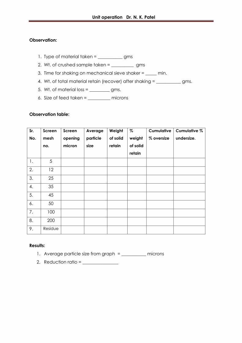
Observation:
1. Type of material taken = ___________ gms
2. Wt. of crushed sample taken = __________ gms
3. Time for shaking on mechanical sieve shaker = _____ min.
4. Wt. of total material retain (recover) after shaking = ___________ gms.
5. Wt. of material loss = _________ gms.
6. Size of feed taken = __________ microns
Observation table:
Sr.
No.
Screen
mesh
no.
Screen
opening
micron
Average
particle
size
Weight
of solid
retain
%
weight
of solid
retain
Cumulative
% oversize
Cumulative %
undersize
1. 5
2. 12
3. 25
4. 35
5. 45
6. 50
7. 100
8. 200
9. Residue
Results:
1. Average particle size from graph = ___________ microns
2. Reduction ratio = ________________
Unit operation Dr. N. K. Patel
PRACTICAL: 3
ROLL CRUSHER
Aim: Crush the given material, in roll crusher and determine average particle size
and reduction ratio.
Requirements: Roll crusher, sieves of different mesh no., mechanical sieve shaker,
weighing balance, weight box.
Theory:
Two heavy smooth faced metal-rolls running on parallel horizontal axis are the
working element of the smooth roll crusher, particles of feed, caught between the
rolls are broken in compression and drop out below. The rolls turn toward each other
at the same speed. They have relatively narrow faces are large in diameter so that
they can hip moderately large lumps. Typical rolls are 24" in diameter with a 12" face
to 78" in diameter with 36" face. Roll speed ranges, from 50 - 300 rpm. Smooth roll
crushers are the secondary crushers with' feed ½ to 3 inch in size and product ½
inch to about 20 mesh.
Reduction Ratio: Reduction ratio is the ratio of diameter of largest particle in feed to
diameter of largest particle in the discharge.
Process:
Clean the roll crusher by running it empty and then with air blower.
Run the crusher empty for few seconds.
Feed the solid material through hopper slowly,
Collect the crushed solid material at the bottom of the crusher using storage
beam.
Analyze the ½ to1kg crushed material by sieves of different mesh numbers
using mechanical sieve shaker, running it for ½ hour.
Weigh the solids retained on each sieve and also residue.
Plot on semi-log graph paper
1. % wt retained v/s average particle size.
2. Cumulative % oversize & undersize v/s particle size.
Unit operation Dr. N. K. Patel
Observation:
1. Type of material taken = ___________ gms
2. Wt. of crushed sample taken = __________ gms
3. Time for shaking on mechanical sieve shaker = _____ min.
4. Wt. of total material retain (recover) after shaking = ___________ gms.
5. Wt. of material loss = _________ gms.
6. Size of feed taken = __________ microns
Observation table:
Sr.
No.
Screen
mesh
no.
Screen
opening
micron
Average
particle
size
Weight
of solid
retain
%
weight
of solid
retain
Cumulative
% oversize
Cumulative %
undersize.
1. 5
2. 12
3. 25
4. 35
5. 45
6. 50
7. 100
8. 200
9. Residue
Results:
1. Average particle size from graph = ___________ microns
2. Reduction ratio = ________________

Unit operation Dr. N. K. Patel
PRACTICAL: 4
BALL MILL
Aim: Grind the given material in ball mill using solid metal balls and determine
average particle size, reduction ratio and Rittingers constant.
Requirements: Ball mill, metal balls, weighing balance, mechanical sieve shaker,
sieves of different mesh nos.
Theory:
Ball mill is a typical revolving mill. A cylindrical shell slowly moving about a
horizontal axis and filled to about half of its volume with the solid and "Grinding
Media". The shell is usually of steel lines with high carbon steel metal silicate rock or
rubber. The grinding media is metal balls in case of ball mill or metal rods, pebbles
etc. Revolving mills may be continuous or batch type. In batch type mill measured
quantity of the solid to be ground is loaded through an opening in the shell, opening
is then closed. Mill is revolved for specified time. It is then stopped and product is
discharged. In ball mill most of the reduction is done by impact as the balls drops
from top. A ball mill may be leaded with balls of different sizes. Heavy balls break
away only large particles end small light particles fall only on small particle.
Action in mil l :
Load of balls in mill should be such that never mill is stopped. The balls occupy
somewhat half the volume of mill. In operation balls tallow the cyclic path they are
picked up by the inside wall of the mill and carried to the top where they break
contact with the wall, fall on material and again at the bottom to be picked again
and recycled. Centrifugal force keeps the ball in contact with the wall. Balls do
some grinding by slipping and rolling over each other, most of the grinding at the
zone of impact.
Reduction ratio:
Reduction ratio is the ratio of diameter of largest particle in feed to discharge.
Unit operation Dr. N. K. Patel
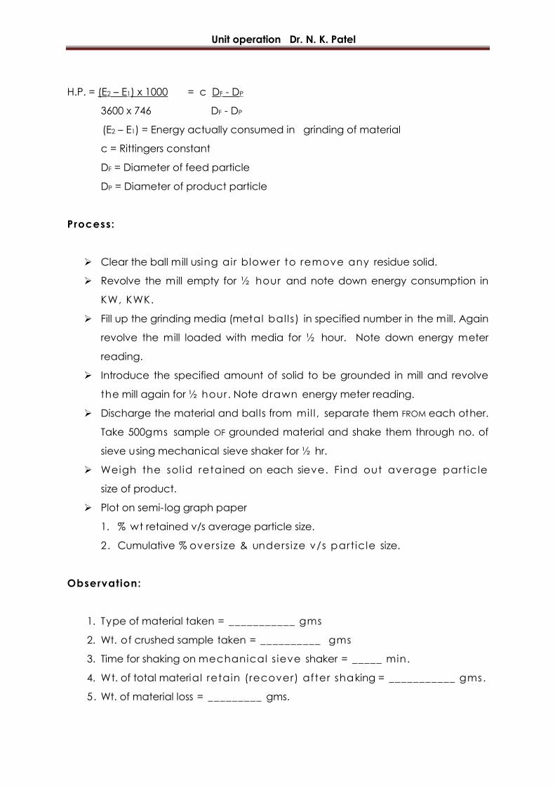
H.P. = (E2 – E1) x 1000 = c DF - DP
3600 x 746 DF - DP
(E2 – E1) = Energy actually consumed in grinding of material
c = Rittingers constant
DF = Diameter of feed particle
DP = Diameter of product particle
Process:
Clear the ball mill using air blower to remove any residue solid.
Revolve the mill empty for ½ hour and note down energy consumption in
KW, KWK.
Fill up the grinding media (metal bal ls) in specified number in the mill. Again
revolve the mill loaded with media for ½ hour. Note down energy meter
reading.
Introduce the specified amount of solid to be grounded in mill and revolve
the mill again for ½ hour. Note drawn energy meter reading.
Discharge the material and bal ls from mil l , separate them FROM each other.
Take 500gms sample OF grounded material and shake them through no. of
sieve using mechanical sieve shaker for ½ hr.
Weigh the sol id retained on each sieve. Find out average particle
size of product.
Plot on semi-log graph paper
1. % wt retained v/s average particle size.
2. Cumulative % oversize & undersize v/s particle size.
Observation:
1. Type of material taken = ___________ gms
2. Wt. of crushed sample taken = __________ gms
3. Time for shaking on mechanical s ieve shaker = _____ min.
4. Wt. of total material retain (recover) after shaking = ___________ gms.
5. Wt. of material loss = _________ gms.
Unit operation Dr. N. K. Patel
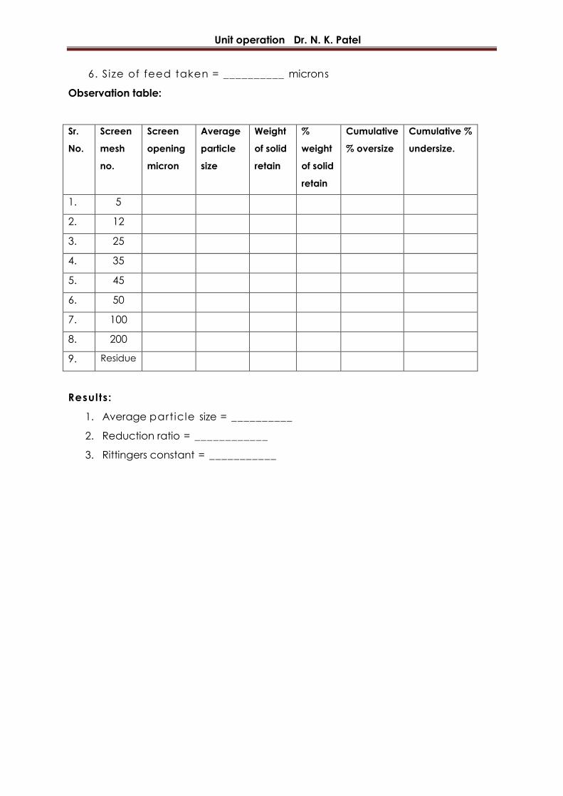
6. Size of feed taken = __________ microns
Observation table:
Sr.
No.
Screen
mesh
no.
Screen
opening
micron
Average
particle
size
Weight
of solid
retain
%
weight
of solid
retain
Cumulative
% oversize
Cumulative %
undersize.
1. 5
2. 12
3. 25
4. 35
5. 45
6. 50
7. 100
8. 200
9. Residue
Results:
1. Average particle size = __________
2. Reduction ratio = ____________
3. Rittingers constant = ___________
Unit operation Dr. N. K. Patel
PRACTICAL: 5
CYCLONE SEPARATOR
Aim: Determination of efficiency of cyclone separator and to plot size v/s
efficiency.
Requirements: Cyclone separator, weighing machine, collecting beams etc.
Efficiency = Wt. of the course materials from separator
Wt. of the material in feed
Theory:
Cyclones are used primarily for separation of solids from fluids and utilize
centrifuge force to effect separation. Such a separation depends not only on
particle size but also on particle density, so that cyclones may be used to effect a
separation on the basis of particle size or particle density but also both.
Apparatus consists essentially of short vertical cylinder, closed by flat or dished
plate on top and by a conical bottom. Air with its load of solid is introduced
tangentially at top of cylindrical portion. Centrifugal forces throw solid particles out
against the wall and they drop into hopper. The outlet for the air is usually in the
center of the top and is also usually provided with a nipple that extends inwardly into
the separator to prevent the air short-circuiting directly from the inlet to the outlet.
Such separators are widely used for the collecting of wood chips, heavy and coarse
dusts and all manner of separations in which the material to be removed is not too
fine. They may also be used for separating heavy of course materials from fine dust.
Process:
Clean the cyclone separator by running it empty
Prepare the difference feed samples using sieves of different mesh number.
Run the cyclone separator empty for few second with fully opened path.
Feed the sample through hopper

Unit operation Dr. N. K. Patel
Run the air blower simultaneously
Collect the separated particles of solid in different collectors from two
different outlets.
Analyze the collected material by sieves and find out weight solid retained on
each sieve.
Repeat the process for number of samples.
Observation table
Sr.
No.
Wt. of sample
F gms
Wt. of course
solid
c gms
Wt. of fine solid
G gms
% efficiency =
wt. of course
Wt. of fine
Avg.
efficiency
Calculation:
% efficiency = wt. of course material from separation
Wt. of fine material in feed
Results:
Average efficiency of cyclone separator as obtained experimentally =
________%

Unit operation Dr. N. K. Patel
PRACTICAL: 6
STUDY OF REFRACTOMETER
Aim: To plot % composition v/s refractive index and determine % composition of
given unknown mixture containing pure liquids by refractometry method.
Apparatus: Refractometer, air blower, burette, test tubes, cotton etc
Chemicals: CCl4, Toluene, Acetone etc.
Process:
Open the prism box of refractometer and clean it with the cotton containing
acetone. Let prism by dry. Now place few drops of pure liquid on the surface of
lower prism. Close the prism box taking care to see that the liquid does not flow
away. A film of liquid will thus be enclosed between prism focus. The cross wires of
the telescope rotating eye-piece and adjust the mirror so as to get good
illumination. Now, turn the prism box slowly backwards and forwards until the field of
view becomes partially illuminated and partially dark. The edge of the light band will
show a coloured fringe in ease of wide light source. Rotate the compensator until
the coloured fringes disappear and lighted band shows a sharp edge. Now, rotate
the prism box until this sharp edge is in co-incidence with the intersection of cross
wire in telescope. Read directly index of refraction on the scale. Refractive index
can be read directly up to the third decimal point and the fourth can be estimated
with accuracy of about ± 0.0002.
Repeat the above process for pure liquid to determine refractive index.
Prepare the different mixture using two pure liquids on volumetric basis. Determine
the refractive indices of all the prepared samples. On two co-ordinate graph paper
plot volumetric composition of prepared mixture v/s refractive indices. Thus,
prepare a calibration curve. Also determine refractive indices of given unknown
samples and determine composition with help of calibration curve plotted,
Unit operation Dr. N. K. Patel
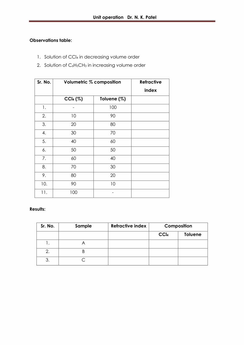
Observations table:
1. Solution of CCl4 in decreasing volume order
2. Solution of C6H5CH3 in increasing volume order
Sr. No. Volumetric % composition Refractive
index
CCl4 (%) Toluene (%)
1. - 100
2. 10 90
3. 20 80
4. 30 70
5. 40 60
6. 50 50
7. 60 40
8. 70 30
9. 80 20
10. 90 10
11. 100 -
Results:
Sr. No. Sample Refractive index Composition
CCl4 Toluene
1. A
2. B
3. C
Unit operation Dr. N. K. Patel
PRACTICAL: 7
SIMPLE DISTILLATION
Aim: Study of simple distillation and determination of the relative volatility of the
binary system
Apparatus: Distillation flask, condenser, Measuring cylinder, Refractometer, beaker,
Heater etc.
Chemicals: CCl4, Toluene, Acetone etc
Theory:
In simple distillation the vapour generated by boiling the liquid is withdrawn
from contact with the liquid and condensed as fast as it is formed, Since the vapours
are richer in the more volatile component than is the liquid left in the still, the liquid
residue gets progressively weaker in the component. Hence the composition of this
residue and therefore that of the vapour generated from it’s continuously changes.
This changing relationship is expressed well by Rayleigh’s equation
ln F/W = dx/y – x
Where, F = no. of moles of feed
W = no. of moles of residue
X = mole fraction of more volatile component in vapour
Simple distillation is resorted to when the components to be separated have
widely different in boiling point and where method giving sharp separation is not
necessary. The apparatus for simple distillation consists of boiler and a condenser.
The relative volatility is calculated by using the relationship as follows
ln F/w = 1___ ln XF (1 – Xw) + ln 1 – Xw
α – 1 Xw ( 1 – XF) 1 - XF
Where, F = total nos. of moles of feed
W = total nos. of moles of residue
XF = mole fraction of MVC in feed
Xw = mole fraction of MVC in residue
Unit operation Dr. N. K. Patel
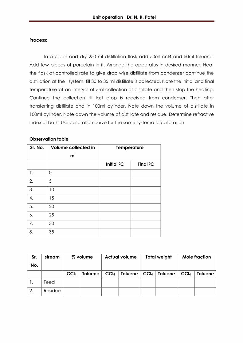
Process:
In a clean and dry 250 ml distillation flask add 50ml ccl4 and 50ml toluene.
Add few pieces of porcelain in it. Arrange the apparatus in desired manner. Heat
the flask at controlled rate to give drop wise distillate from condenser continue the
distillation at the system, till 30 to 35 ml distillate is collected. Note the initial and final
temperature at an interval of 5ml collection of distillate and then stop the heating.
Continue the collection till last drop is received from condenser. Then after
transferring distillate and in 100ml cylinder. Note down the volume of distillate in
100ml cylinder. Note down the volume of distillate and residue. Determine refractive
index of both. Use calibration curve for the same systematic calibration
Observation table
Sr. No. Volume collected in
ml
Temperature
Initial 0C Final 0C
1. 0
2. 5
3. 10
4. 15
5. 20
6. 25
7. 30
8. 35
Sr.
No.
stream % volume Actual volume Total weight Mole fraction
CCl4 Toluene CCl4 Toluene CCl4 Toluene CCl4 Toluene
1. Feed
2. Residue

Unit operation Dr. N. K. Patel
Feed Volume Refractive index
Residue
Distillate
Result:
Relative volatility of the given system as determined experimentally = ____________
Unit operation Dr. N. K. Patel
PRACTICAL: 8
RECTIFICATION
Aim: To study the rectification characteristic of binary system.
Apparatus: Distillation flask, fractionating column, condenser, heating media,
refractometer, measuring cylinder, test tubes.
Chemicals: CCl4, Toluene, Acetone etc
Theory:
Continuous rectification or fractionation is a multistage counter current
distillation separation. By this for a given binary system it is possible to separate
solution into its component recover}' in state of purify desired. It is frequently used
operation method. The rectification unit consist of
(a) A still or re-boiler in which vapour is generated
(b) A rectifying or fractionating column through which this vapour rises in counter
current contact with a descending stream of liquid,
(c)A condenser, which condenses all the vapour leaving the top of the column
sending part of this condensed liquid back to the column to decant counter to the
rising vapours, and delivering the rest of the condensed liquid as product. As the
liquid stream descends the column it is progressively enriched with the high-boiling
constituent and as the vapour our stream ascends it is progressively enriched with
the low-boiling constituent, The column then becomes an apparatus for bringing
these stream into intimate contact, so that the vapour stream tends be condense
the high-boiling constituent from the vapour. The top of the column is cooler than
the bottom, so that the liquid stream becomes progressively hotter as it descends
and the vapour stream becomes, progressively cooler as it rises. This heat transfer is
accomplished by actual contact of liquid and vapour and for this purpose, likewise,
effective contacting is desirable.
Unit operation Dr. N. K. Patel
Process:
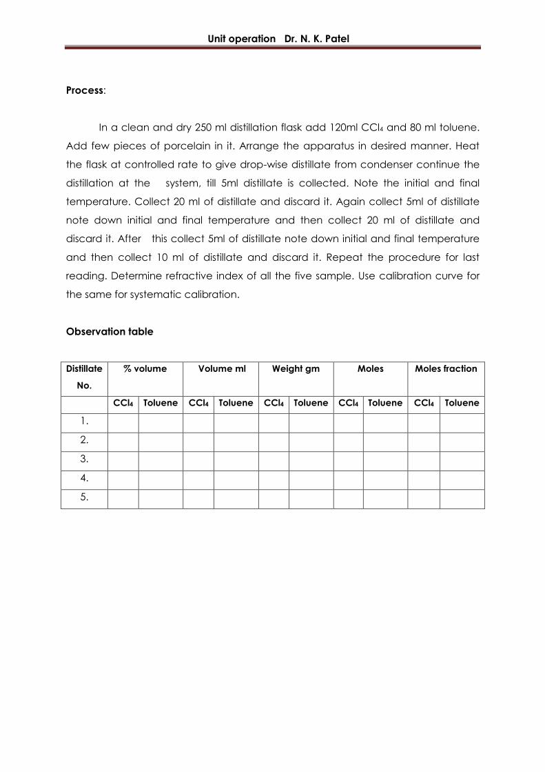
In a clean and dry 250 ml distillation flask add 120ml CCl4 and 80 ml toluene.
Add few pieces of porcelain in it. Arrange the apparatus in desired manner. Heat
the flask at controlled rate to give drop-wise distillate from condenser continue the
distillation at the system, till 5ml distillate is collected. Note the initial and final
temperature. Collect 20 ml of distillate and discard it. Again collect 5ml of distillate
note down initial and final temperature and then collect 20 ml of distillate and
discard it. After this collect 5ml of distillate note down initial and final temperature
and then collect 10 ml of distillate and discard it. Repeat the procedure for last
reading. Determine refractive index of all the five sample. Use calibration curve for
the same for systematic calibration.
Observation table
Distillate
No.
% volume Volume ml Weight gm Moles Moles fraction
CCl4 Toluene CCl4 Toluene CCl4 Toluene CCl4 Toluene CCl4 Toluene
1.
2.
3.
4.
5.

Unit operation Dr. N. K. Patel
PRACTICAL: 9
STEAM DISTILLATION
Aim: Determine the vapor efficiency by steam distillation of the given sample.
Requirements: Distillation flask, Boiler, Condenser, 25 cc measuring cylinder.
Process:
Take exactly about 100ml of the sample in distillation flask. Arrange the
apparatus as desired. Generate the steam in boiler and pass into distillation flask.
Liquid boils condense the vapors and collect the distillate in 25 ml measuring
cylinder Note down the distillation temperature. Allow distillate to separate into two
layers. Note atmospheric temperature.
Observations table:
Sr.
No.
Sample Total
Volume
collected
Volume of
upper
layer
Volume of
lower layer
Vaporization
efficiency
1.
2.
3.
Result: The vapor efficiency of given liquid sample = ____________
Unit operation Dr. N. K. Patel
PRACTICAL: 10
LIQUID - LIQUID EXTRACTION
Aim: To determine equilibrium solubility of following system at room temperature
and to plot triangular diagrams.
1. CHCl3- H2O - CH3COOH
2. CCl4 - H2O – CH3COOH
Apparatus: Burette, pipette, stand, funnels, beaker etc.
Chemicals: Chloroform, CCl4, CH3COOH and Acetone.
Theory:
Liquid-liquid extraction may be used to effect the removal of one or more of
the components present in a solution by treatment with a suitable solvent. It
may also be thought of as an alternative process of distillation.
It is to be considered where separation by distillations is difficult to accomplish
for any one of several reasons.
1. The boiling points of the constituents may be too close together or
2. Too high for the heating media available or
3. So high that one or more of the constituents may decompose at the
temperature involved.
It has been of particular importance in the petroleum field, where solvent
refining of lubricating oil fractions has been used widely to improve their
viscosity characteristics. In addition, the recovery of aromatic from paraffinic
and naphthenic hydrocarbons and caustic extraction for the removal of
sulfur compounds from gasoline are extensively used in the field. Liquid-liquid
extraction is used for the refining of vegetable oils, using furfural as a solvent.
It is also applied in the manufacture of pharmaceuticals, particularly the
antibiotics.
In liquid-liquid extraction two phases involve are liquid simply solute is
removed from one phase (raffinate) by solvent into other phase (extract).
Separation of components of liquid mixture by treatment with solvent in which

Unit operation Dr. N. K. Patel
one or more of desired component is preferentially soluble known as "liquid-
liquid extraction" Overall extraction process comprising of bringing solvent
and solution in intimate contact. Separating the resulting two phases and
removed and recovered of solution from each phase.
Compositions of ternary system are conveniently represented by points on
triangle diagram covering the entire composition range. Composition may be
expressed as mass or mole fraction basis. Such diagrams are used to show
phase relationship in the ternary liquid system. When two component B and C
are particularly miscible with each other and complete miscibility exist
between B and A, C and A solubility relationship all shown as
Curve F.P.G. represents solubility limit and curve is known as "saturation
curve": Area under this curve represents two phase region which will split up
into layer in equilibrium with each other. These phases are known as
“conjugate phases”. Line ER connecting conjugate phases is known as "Tie
line". Number of tie line may be constructed in two phase region. Tie line
disappeared at point 'P' known as 'Plait point’ where two conjugate phases
become mutually soluble.
Process:
Part: I
10 ml of distilled water is taken in a clean 150 ml conical flask add 1 ml of
CHCl3. Two phases are observed. In the content of the flask now add drop-wise
acetic acid with the help of burette till a single phase is observed. Note the amount
of acid added. Again adds 1 ml of CHCl3 in the same flask and add acetic acid till a
single phase is observed. Note the amount of acid added. Continue the process
upto the addition of 10 ml of CHCl3.
Unit operation Dr. N. K. Patel
Part II
10 ml of CHCl3 is taken in a clean and dry conical flask. Add 1 ml of water.
Two phases are obtained in the flask. Add acetic acid drop-wise to get a single
phase. Repeat the process for the addition of 10 ml of water. Note the amount of
acetic acid added for the addition of each ml of water.
Result: The equilibrium solubility of a ternary systems
1. CHCl3- H2O - CH3COOH
2. CCl4 - H2O – CH3COOH
are shown on triangular graph.
Unit operation Dr. N. K. Patel
PRACTICAL: 11
STUDY OF CRYSTALLIZATION WITHOUT AND WITH SEEDING
Aim: To determine practical yield of crystallization of hydrated copper sulfate
crystals from its saturated solution at 50°C carrying out crystallization.
1. Without seeding
2. With seeding
Apparatus: Evaporating dishes, beaker, funnel, burette, thermometer etc.
Chemicals: Hydrated CuSO4 Crystals.
Theory:
Crystallization process is one in which new phase is created within
homogenous mass by formation of solid particles. The drying force for crystallization
process is different in the solubility. In the saturated solution the crystal will neither
form nor grow but for crystallization system should be supersaturated.
Supersaturated may be obtained by
Simple cooling
Evaporating a portion of solvent
And adding thin substances, which decrease solubility of dissolved solid,
Crystallization process completes in two steps:
Nucleus formation
(1) Crystal growth
Addition of artificial nucleation supports growth and yield of crystals. In initial
crystallization seeding is practiced to favour quality and yield.
Process:
Take 2 dry and clean evaporating dishes and label them A and B. Weigh the
dishes accurately. Place 10.45 gm CuSO4.5H2O crystal and 16.5 ml of water in each
dish using the burette. Heat the contents of each dish slowly by stirring using glass
rod. Dissolve the crystals in water maintaining the temperature to 50°C to get
saturated solution. Remove the dishes from burner cool dish A without addition to
room temperature. Cool dish B after immediately adding 0.4 gm CuSO4.5H2O

Unit operation Dr. N. K. Patel
crystals. Cool the dishes to room temperature. Determine the weight of dishes with
their contents. Filter and dry crystals in air. Determine weight of dried crystals from
both dishes separately.
Observation:
Sr.
No.
Observations Without seeding With seeding
1. Weight of dish
2. Weight of dish + CuSO4.5H2O
3. Weight of dish + solution (after
cooling)
4. Weight of crystal after cooling
5. Weight of seed added
6. Time for cooling
Calculation:
For theoretical yield of crystals
1. Without seeding
10.45 = C + (3-1-C)25/100
C =
2. With seeding
(10.45 + 0.4) = C + (3-1-C)25/100
C =
3. % yield
Results:
Sr.
No.
Types of crystallization Theoretical
yield
Practical yield % yield
1. Without seeding
2. With seeding
Unit operation Dr. N. K. Patel
PRACTICAL: 12
CRYSTALLIZATION (EFFECT OF COMMON ION)
Aim: To study the % yield of crystallization of Ba(NO3)2 crystal from its saturated
solution at 700C by carrying out crystallization using
1. Simple cooling
2. Addition of common ion ( nitric acid)
Requirement: Ba(NO3)2, Beakers, HNO3 etc.
Process:
In 500ml clean and dry beaker take 200ml of distilled water. Heat it to 700C.
Add 87gms of Ba(NO3)2 crystal in it. Stir continuously the content of beaker by
maintaining temperature 700C until all crystal has been dissolved. Immediately
divided the solution into two equal parts. Add 10ml conc. HNO3 to one beaker. Allow
both beaker to cool to room temperature. Separate the crystal and dry it. Weight
out the crystal exactly. Also measure the volume of mother liquor
Calculation:
Ba(NO3)2 in mother liquor
X1 = V1 X 11.6 X2 = V2 X 11.6
100 100
% yield = C1 X 100 % yield = C2 X 100
C1 + X1 C2 + X2
Results:
Yield of crystallization
1. Simple cooling = ______%
2. By adding common ion nitric acid = _____%
Unit operation Dr. N. K. Patel
PRACTICAL: 13
BATCH SETTLING TEST
Aim: To verify law of settling and to find out the constants in the equation aub.
Requirements: CaCO3 powder, Measuring cylinder (1 liter), glass stirrer, stops watch.
Theory:
Rate of settling decreases with the initial concentration of slurry, owing to
measured effective density and viscosity of the media through which the particle
settles. The curve plotted shows the effect usually to be expected when slurry of
same substances are settling in the column of the same height. Various attempts are
made to predict the effect of concentration on the settling rate from the knowledge
of curve at one or more concentration. It has been established that settling rate is
related to initial concentration
of any type of slurry as
Z/Zi = awb
Z = Height of slurry at infinite time
W= Concentration of slurry
a & b= Empirical constants
Zi= Height of slurry initially
Process:
Prepare the slurries of CaCO3 in water of concentration 20 gm/liter, 30
gms/liter and 40gms/liter in different beakers. Now take three measuring cylinders of
one liter capacity and fill them with prepared slurry. Initial heights of the slurries are
noted. Cylinders are numbered as 1, 2 and 3. Slurries are stirred uniformly using glass
rod to have slurry of uniform density. Now allow the slurry to settle without any
disturbance. The time corresponding to position of demarkation line between clear
liquid and settling slurries is noted in each cylinder. After noting sufficient readings
cylinders are stand undisturbed for long time to note the height of infinite time.
Unit operation Dr. N. K. Patel
Observation table:
Sr.
No.
Height of
slurry cm
Time in second
20gm/lit 30gm/lit 40gm/lit
I II I II I II
Result: The value of constants
a =
b =
Unit operation Dr. N. K. Patel
PRACTICAL: 14
ADSORPTION OF OXALIC ACID ON CHARCOAL
Aim: To study the adsorption of oxalic acid on charcoal.
Requirement: Conical flask, stopper bottle, funnel, oxalic acid solution, NaOH
solution
Process:
Prepare five sets of water and oxalic acid as shown in observation table. Add
one gram of activated charcoal. Mix well and stir to obtain equilibrium. Allow the
solution to stand for half an hour. Filter the solution and titrate 5ml of it with 0.1N
NaOH solution. Add phenolphthalein indicator. Also take blank reading.
Observation table:
Sr.
No.
0.5M
oxalic
acid
Water Burette
reading
Conc. of acid solution Adsorption
coefficient
(X)
Log
C2
Log
X/M
Initial
R1
Final
R2
C1=(0.1xR1)/5 C2=(0.1xR2)/5
1.
2.
3.
4.
5.
Result: Adsorption of acid on charcoal is = __________________
Unit operation Dr. N. K. Patel
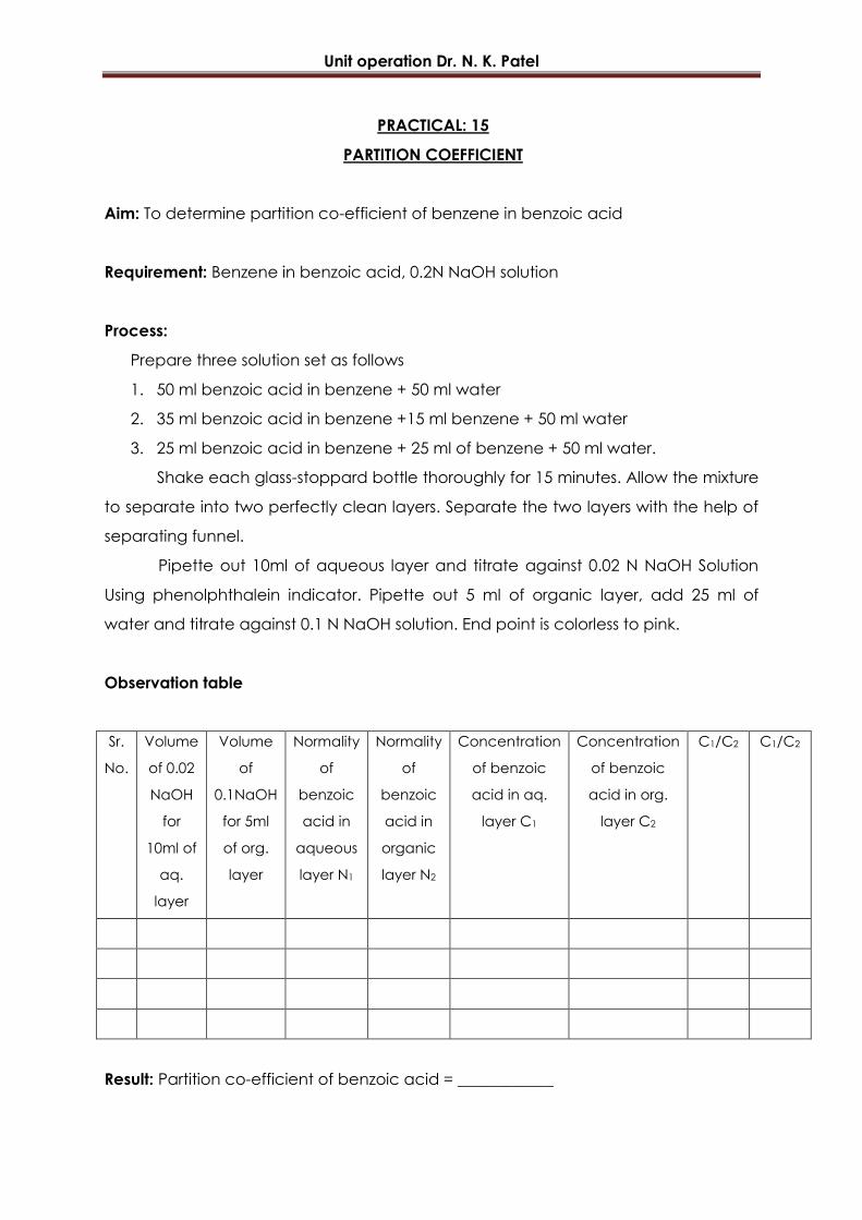
PRACTICAL: 15
PARTITION COEFFICIENT
Aim: To determine partition co-efficient of benzene in benzoic acid
Requirement: Benzene in benzoic acid, 0.2N NaOH solution
Process:
Prepare three solution set as follows
1. 50 ml benzoic acid in benzene + 50 ml water
2. 35 ml benzoic acid in benzene +15 ml benzene + 50 ml water
3. 25 ml benzoic acid in benzene + 25 ml of benzene + 50 ml water.
Shake each glass-stoppard bottle thoroughly for 15 minutes. Allow the mixture
to separate into two perfectly clean layers. Separate the two layers with the help of
separating funnel.
Pipette out 10ml of aqueous layer and titrate against 0.02 N NaOH Solution
Using phenolphthalein indicator. Pipette out 5 ml of organic layer, add 25 ml of
water and titrate against 0.1 N NaOH solution. End point is colorless to pink.
Observation table
Sr.
No.
Volume
of 0.02
NaOH
for
10ml of
aq.
layer
Volume
of
0.1NaOH
for 5ml
of org.
layer
Normality
of
benzoic
acid in
aqueous
layer N1
Normality
of
benzoic
acid in
organic
layer N2
Concentration
of benzoic
acid in aq.
layer C1
Concentration
of benzoic
acid in org.
layer C2
C1/C2 C1/C2
Result: Partition co-efficient of benzoic acid = ____________

Unit operation Dr. N. K. Patel
PRACTICAL: 16
PLATE AND FRAME FILTER PRESS
Aim: Study the variation of rate of filtration with time using a plate and frame filter
press, under constant pressure filtration.
Requirements: Plate and frame- filter press, slurry preparing tank, weighing balance.
Theory:
A filter press contains a set of plates and frames designed to provide a series
of compartments in which solid may collect. The plates are covered with a filter
medium such as canvas. Slurry is admitted to each compartment under pressure,
liquid passes through canvas and out a discharge pipe leaving a wet cake of solids
behind.
Plates of filter press may be circular or square, vertical or horizontal. Plates
and frames of 6" to 56" on a side with 1/4” to 2” thickness set vertically in a metal
rack, with the cloth covering the face of each plate and are squeezed tightly
together by a screw. Slurry enters at one end of the assembly of plates and frames.
It passes through the channel running lengthwise through one corner of assembly.
Auxiliary channels "carry slurry from main inlet channel into each frame, solids are
deposited on the cloth covered faces of the plates. After assembly of press, slurry is
admitted from a pump under press. Filtration is continued until liquor no longer flow
out of the discharge. This occurs when frame are fully of solids and no more slurry
can enter. The press is then opened, cake of solids scraped of the filter medium and
drooped to storage bin.
Mean speciriv cake resistance = Kp A2 (-P)g
P
Filter cake or filter media resistance (Rm) = B° A° (-P) gc
p= viscosity of fluid
A = Effective area of filtration
Kp = Constant
(Calculated from graph ploted between V & T/V)
B = Intercept
Unit operation Dr. N. K. Patel
Kp = Slope
C = Mass of solid deposited per unit volume of filtration
gc = Gravitational constant
Process
Clean the each part of filter press using water as well as slurry preparing tank.
Prepare the slurry of CaCO3 powder in water of concentration as specified in
slurry preparing tank and arrange the equipment as desirable.
Stirrer the slurry for few minutes using mechanical agitation to get the slurry of
uniform density. Allow the uniform slurry to come in the filter press.
Slurry will get filtered as a result filtrate will come out through various outlet
cooks of plates and solid will be retained in between the filter cloth supported
over frame.
Collect the filtration in a graduate collecting tank noting the time
simultaneously for collection of each half liter of filtrate.
Unit operation Dr. N. K. Patel
PRACTICAL: 17
PUMPS AND VALVES
Aim: Study of Pumps and Valves
Valves:
The valve is a device used either to control the flow rate or to shut off the flow
of fluid through pipelines and process equipments. Various types of valves are used
in chemical industry and are constructed out of variety of materials based upon the
service requirements. The various type of valves in use are:
1. Gate valve 4. Plug valve 7. Butterfly valve
2. Globe valve 5. Diaphragm valve 8. Check/non return valve
3. Ball valve 6. Needle valve 9. Control valve etc.
The gate valve is commonly used to minimize the pressure drop in open
position and to stop the flow rather than controlling it. The globe valve is used to
control the flow but the pressure drop through globe valve is much greater than that
for gate valve. The needle valve is a modification of globe valve and generally used
for accurate control of flow. The plug valve and ball valve are used for on-off service
and operate through 90°. The non-return valve is used when unidirectional flow is
desired.
Diaphragm valves are used for fluids such as viscous liquids, slurries or
corrosive liquids. They make a use of flexible diaphragm usually of rubber. The
butterfly valve is used in large size pipeline and operates on same principle as a
damper in a stove pipe. The control valves are used in modern chemical processes
for controlling flow automatically. These, valves are operated either electrically or
pneumatically. Fig. 7.2 shows various types of valves.


PRACTICAL: 18
HEAT EXCHANGER
Aim: Study of heat exchanger
Double pipe heat exchanger:
It is the simplest type of heat exchanger used in industry. It is used when
required heat transfer area is relatively small.
It consists of concentric pipes, connecting tees, return heads and a return
bends. The packing glands support inner pipe within the outer pipe. The double pipe
heat exchanger arranged in two legs [i.e. when two lengths of inner pipe are
connected by return bend.] as shown in Fig. 5.1 is known as a single hair-pin. The
tees are provided with nozzles or screwed connections for permitting the entry and
exit of the annulus fluid which crosses from one leg to the other through the return
head. The return bend connects two legs of inner pipes to each other. This
exchanger can be very easily assembled in any pipe-fitting shop as it consists of
standard parts and it provides inexpensive heat transfer surface. In this exchanger,
one of the fluids flows through inside pipe and other fluid flows through the annular
space created between two concentric pipes either in co-current or counter
current fashion. It is usually employed for decreasing the temperature of hot fluid
with the help of cold fluid when flow rates are low.
These exchangers are usually assembled in effective lengths of 3.65, 4.57, 6 m.
The distance in each leg over which the heat transfer occurs is termed as the
effective length.
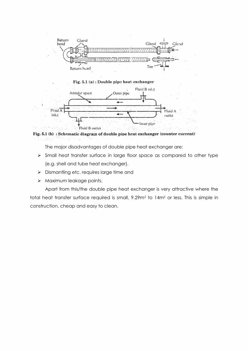
The major disadvantages of double pipe heat exchanger are:
Small heat transfer surface in large floor space as compared to other type
(e.g. shell and tube heat exchanger).
Dismantling etc. requires large time and
Maximum leakage points.
Apart from this/the double pipe heat exchanger is very attractive where the
total heat transfer surface required is small, 9.29m2 to 14m2 or less. This is simple in
construction, cheap and easy to clean.

PRACTICAL: 19
REYNOLDS EXPERIMENTS
Aim: To study the Reynolds experiments.
Requirements: Reynolds apparatus
Process:
The experimental set up is shown in figure. It consists of horizontal glass tube
with flared entrance immersed in a glass walled constant head tank filled with
water. The flow of water through glass tube can be adjusted to any desired value by
means of valve provided at the out let. The capillary tube connected to small
reservoir containing water soluble dye is provided at the center of flared entrance of
glass tube for injecting dye solution in the form of fine or thin filament into stream of
water.
By introducing water soluble dye into flow of water, the nature of flow could
be observed. At low flow rates, the filament of coloured water retained at the axis of
tube i.e. It flowed along with the main stream without any lateral mixing. These
indicate that flow was in the form of parallel streams which did not interfere with
each other. This type of flow patterns is known as laminar or streamlines flow. As the
flow rate is increase a velocity is reached which is known as critical velocity,
oscillation appears in the coloured filament, it than broken into eddies causing
dispersion across die tube section. This type of flow pattern is known as turbulent
flow. In between, the laminar and turbulent flow is a transition flow. Reynolds
observed that the critical velocity for transition from laminar to turbulent depends
upon the diameter of pipe, average velocity of flowing fluid, density of fluid and
viscosity of fluid.
Results: Two types of flow were observed.