Embed Size (px)
Citation preview
ENERGY PORTION READING MATERIAL FOR EES
UNIT 2
Introduction to thermal and Hydro Power Plant
Contents
List of Figures iv
List of Table vi
1 Thermal Power Plant (Coal Based) 1
1.1 Introduction: . . . . . . . . . . . . . . . . . . . . . . . . . . . . . . . . . . . 1
1.2 Rankine cycle . . . . . . . . . . . . . . . . . . . . . . . . . . . . . . . . . . . 1
1.3 Boilers; . . . . . . . . . . . . . . . . . . . . . . . . . . . . . . . . . . . . . . . 3
1.3.1 Other components installed in boiler: . . . . . . . . . . . . . . . . . . 6
1.4 Steam Turbine . . . . . . . . . . . . . . . . . . . . . . . . . . . . . . . . . . 7
1.5 Condenser : . . . . . . . . . . . . . . . . . . . . . . . . . . . . . . . . . . . . 8
1.6 Coal Treatment . . . . . . . . . . . . . . . . . . . . . . . . . . . . . . . . . . 10
2 Introduction to Hydro Power Plant 12
2.1 Introduction . . . . . . . . . . . . . . . . . . . . . . . . . . . . . . . . . . . . 12
2.1.1 Catchment Area And Water Reservoir : . . . . . . . . . . . . . . . . . 15
2.1.2 Dam And The Intake: . . . . . . . . . . . . . . . . . . . . . . . . . . 17
2.1.3 Inlet Water Ways: . . . . . . . . . . . . . . . . . . . . . . . . . . . . . 19
2.1.4 Power House And Equipments: . . . . . . . . . . . . . . . . . . . . . 25
2.1.5 Tail Race And Outlet Water Way: . . . . . . . . . . . . . . . . . . . . 26
2.2 Classi�cation Of Hydraulic Power Plant : . . . . . . . . . . . . . . . . . . . . 28
2.2.1 Classi�cation based on hydraulic characteristics: . . . . . . . . . . . . 28
2.2.2 Classi�cation based on Head: . . . . . . . . . . . . . . . . . . . . . . 30
2.2.3 Classi�cation according to the nature of load: . . . . . . . . . . . . . 31
2.2.4 Classi�cation based on plant capacity: . . . . . . . . . . . . . . . . . 31
2.2.5 Classi�cation based on turbine characteristics i.e speed . . . . . . . . 32
ii

3 Things you should know: 33
4 Bibliography 34
iii
List of Figures
1.1 Rankine cycle used in steam power plant or line diagram of thermal powerplant . . . . . . . . . . . . . . . . . . . . . . . . . . . . . . . . . . . . . . . 2
1.2 Thermal Power plant . . . . . . . . . . . . . . . . . . . . . . . . . . . . . . . 2
1.3 Line diagram of thermal power plant . . . . . . . . . . . . . . . . . . . . . . 3
1.4 Water Tube Boiler . . . . . . . . . . . . . . . . . . . . . . . . . . . . . . . . 4
1.5 Fire Tube Boiler . . . . . . . . . . . . . . . . . . . . . . . . . . . . . . . . . 5
1.6 Thermal power plant diagram showing Superheater and economizer and pul-verizing mill . . . . . . . . . . . . . . . . . . . . . . . . . . . . . . . . . . . . 7
1.7 Steam Turbine . . . . . . . . . . . . . . . . . . . . . . . . . . . . . . . . . . 8
1.8 Steam turbine internals . . . . . . . . . . . . . . . . . . . . . . . . . . . . . . 8
1.9 cooling towers . . . . . . . . . . . . . . . . . . . . . . . . . . . . . . . . . . . 9
1.10 Power plant showing coal treatment . . . . . . . . . . . . . . . . . . . . . . . 10
1.11 another diagram of thermal power plant . . . . . . . . . . . . . . . . . . . . 10
1.12 Energy conversion diagram in a thermal power plant . . . . . . . . . . . . . 11
2.1 A basic hydropower plant . . . . . . . . . . . . . . . . . . . . . . . . . . . . 14
2.2 Line diagram of a basic hydro power plant . . . . . . . . . . . . . . . . . . . 15
2.3 Catchment Area.1 . . . . . . . . . . . . . . . . . . . . . . . . . . . . . . . . . 16
2.4 catchment area.2 . . . . . . . . . . . . . . . . . . . . . . . . . . . . . . . . . 16
2.5 Hoover Dam . . . . . . . . . . . . . . . . . . . . . . . . . . . . . . . . . . . . 18
2.6 Tunnel . . . . . . . . . . . . . . . . . . . . . . . . . . . . . . . . . . . . . . . 19
2.7 Penstock . . . . . . . . . . . . . . . . . . . . . . . . . . . . . . . . . . . . . . 20
2.8 Hydropower plant showing surge tank . . . . . . . . . . . . . . . . . . . . . . 21
2.9 Position of surge tank in an mountain inbuilt penstock . . . . . . . . . . . . 22
2.10 Forebay in a hydropower plant . . . . . . . . . . . . . . . . . . . . . . . . . . 23
2.11 Forebay . . . . . . . . . . . . . . . . . . . . . . . . . . . . . . . . . . . . . . 24
iv

2.12 Spillway . . . . . . . . . . . . . . . . . . . . . . . . . . . . . . . . . . . . . . 25
2.13 Parts of Power house equipments . . . . . . . . . . . . . . . . . . . . . . . . 26
2.14 Draft Tube . . . . . . . . . . . . . . . . . . . . . . . . . . . . . . . . . . . . 27
2.15 Tail Race . . . . . . . . . . . . . . . . . . . . . . . . . . . . . . . . . . . . . 28
2.16 Pumped Storage Plant . . . . . . . . . . . . . . . . . . . . . . . . . . . . . . 29
2.17 electricity demand load curve . . . . . . . . . . . . . . . . . . . . . . . . . . 30
2.18 Basic Hydro-Turbine . . . . . . . . . . . . . . . . . . . . . . . . . . . . . . . 32
v

List of Tables
vi
Chapter 1
Thermal Power Plant (Coal Based)
1.1 Introduction:
A thermal power station is a power plant in which the prime mover is steam driven. Wateris heated, turns into steam and spins a steam turbine which drives an electrical generator.After it passes through the turbine, the steam is condensed in a condenser and recycled towhere it was heated; this is known as a Rankine cycle. The greatest variation in the designof thermal power stations is due to the di�erent fossil fuel resources generally used to heatthe water. Some prefer to use the term energy center because such facilities convert forms ofheat energy into electrical energy. Certain thermal power plants also are designed to produceheat energy for industrial purposes of district heating, or desalination of water, in additionto generating electrical power. Globally, fossil fueled thermal power plants produce a largepart of man-made CO2 emissions to the atmosphere, and e�orts to reduce these are variedand widespread.
1.2 Rankine cycle
A steam power plant continuously converts the energy stored in fossil fuels (coal, oil, naturalgas) or �ssile fuel (uranium, thorium) into shaft work and ultimately into electricity. Theworking �uid is water which is sometimes in the liquid phase and sometimes in the vaporphase during its cycle of operations. Rankine cycle Fig.1.1 shows the �ow diagram of Rankinecycle used in a steam power plant. Energy released by fuel is transferred to water in theBoiler to generate steam at a high pressure and temperature, which then expands in Turbineto a low pressure to produce shaft work. The steam leaving the turbine is condensed intowater in the condenser where cooling water from river or sea circulates carrying away theheat released during condensation. The water (condensate) is then fed back to the boiler bythe pump, and the cycle goes on repeating itself.
1
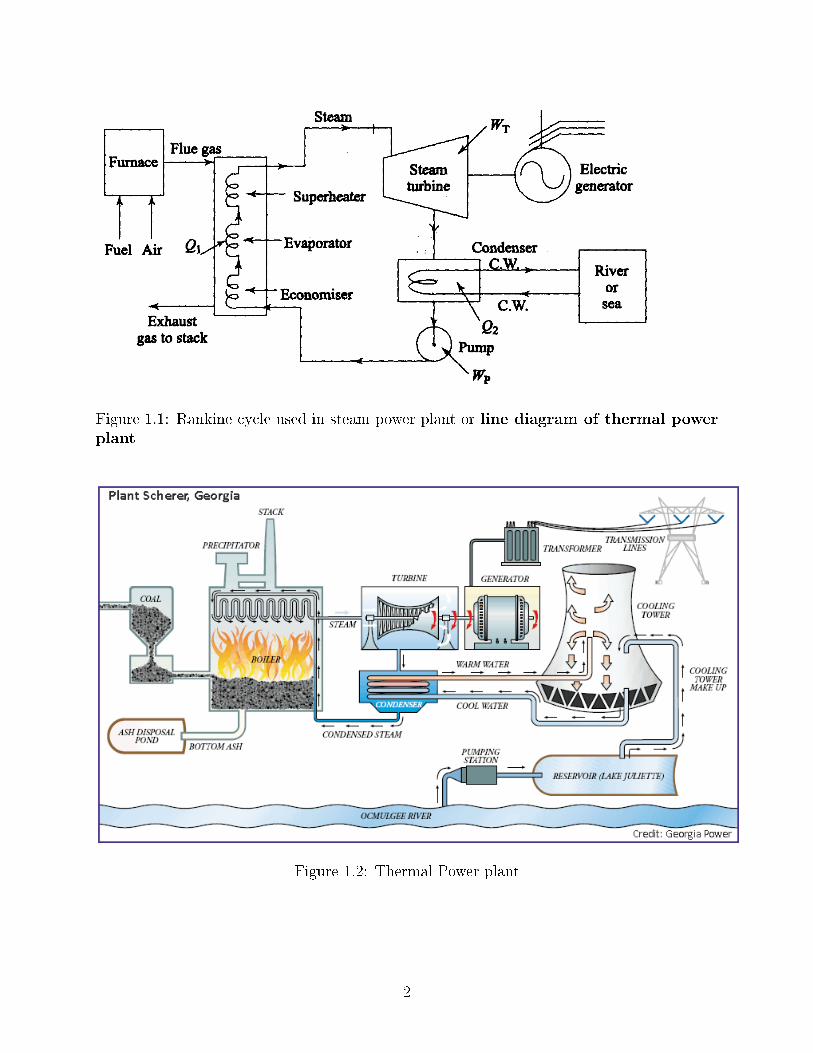
Figure 1.1: Rankine cycle used in steam power plant or line diagram of thermal powerplant
Figure 1.2: Thermal Power plant
2
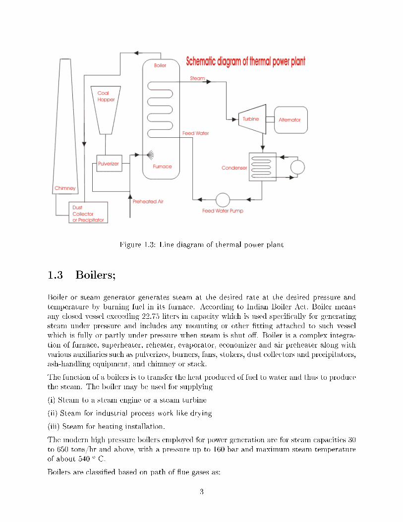
Figure 1.3: Line diagram of thermal power plant
1.3 Boilers;
Boiler or steam generator generates steam at the desired rate at the desired pressure andtemperature by burning fuel in its furnace. According to Indian Boiler Act, Boiler meansany closed vessel exceeding 22.75 liters in capacity which is used speci�cally for generatingsteam under pressure and includes any mounting or other �tting attached to such vesselwhich is fully or partly under pressure when steam is shut o�. Boiler is a complex integra-tion of furnace, superheater, reheater, evaporator, economizer and air preheater along withvarious auxiliaries such as pulverizes, burners, fans, stokers, dust collectors and precipitators,ash-handling equipment, and chimney or stack.
The function of a boilers is to transfer the heat produced of fuel to water and thus to producethe steam. The boiler may be used for supplying
(i) Steam to a steam engine or a steam turbine
(ii) Steam for industrial process work like drying
(iii) Steam for heating installation.
The modern high pressure boilers employed for power generation are for steam capacities 30to 650 tons/hr and above, with a pressure up to 160 bar and maximum steam temperatureof about 540 o C.
Boilers are classi�ed based on path of �ue gases as:
3
1. Water Tube Boiler,
2. Fire tube Boiler
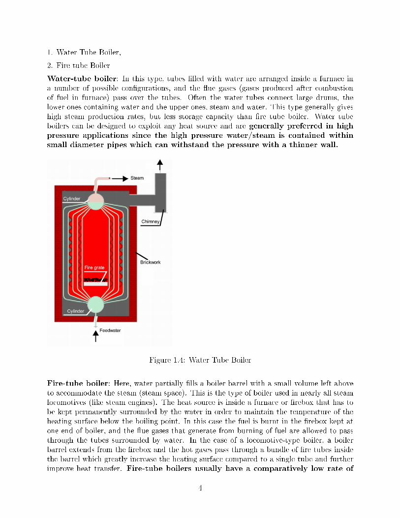
Water-tube boiler: In this type, tubes �lled with water are arranged inside a furnace ina number of possible con�gurations, and the �ue gases (gases produced after combustionof fuel in furnace) pass over the tubes. Often the water tubes connect large drums, thelower ones containing water and the upper ones, steam and water. This type generally giveshigh steam production rates, but less storage capacity than �re tube boiler. Water tubeboilers can be designed to exploit any heat source and are generally preferred in highpressure applications since the high pressure water/steam is contained withinsmall diameter pipes which can withstand the pressure with a thinner wall.
Figure 1.4: Water Tube Boiler
Fire-tube boiler: Here, water partially �lls a boiler barrel with a small volume left aboveto accommodate the steam (steam space). This is the type of boiler used in nearly all steamlocomotives (like steam engines). The heat source is inside a furnace or �rebox that has tobe kept permanently surrounded by the water in order to maintain the temperature of theheating surface below the boiling point. In this case the fuel is burnt in the �rebox kept atone end of boiler, and the �ue gases that generate from burning of fuel are allowed to passthrough the tubes surrounded by water. In the case of a locomotive-type boiler, a boilerbarrel extends from the �rebox and the hot gases pass through a bundle of �re tubes insidethe barrel which greatly increase the heating surface compared to a single tube and furtherimprove heat transfer. Fire-tube boilers usually have a comparatively low rate of
4
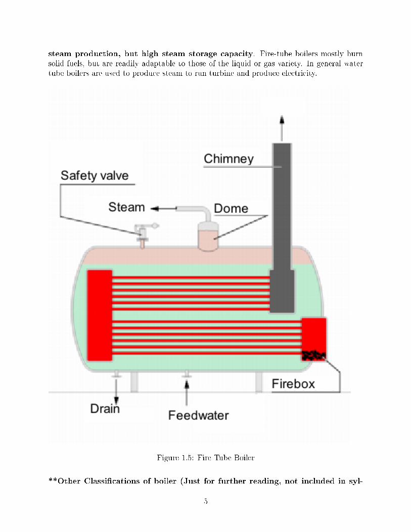
steam production, but high steam storage capacity. Fire-tube boilers mostly burnsolid fuels, but are readily adaptable to those of the liquid or gas variety. In general watertube boilers are used to produce steam to run turbine and produce electricity.
Figure 1.5: Fire Tube Boiler
**Other Classi�cations of boiler (Just for further reading, not included in syl-
5
labus)**
The boilers may be classi�ed as follows:
1. Horizontal, Vertical or Inclined: If the axis of the boiler is horizontal, the boiler is calledas horizontal, if the axis is vertical, it is called vertical boiler and if the axis is inclined it isknown as inclined boiler.
2. Externally �red and Internally �red: The boiler is known as externally �red if the furnaceis outside the boiler shell.(e.g. Babcock and Wilcox, Stirling) In case of internally �redboilers, the furnace is located inside the boiler shell. (e.g. Cochran,Lancashire)
3. Forced circulation and Natural circulation: In forced circulation type of boilers, thecirculation of water is done by a forced pump. (e.g. Velox, Lamont, Benson) In naturalcirculation type of boilers, circulation of water in the boiler takes place due to naturalconvection currents produced by the application of heat. (e.g.Lancashire, Babcock andWilcox)
4. High pressure and Low pressure boiler: The boilers which produce steam at pressures of80 bar and above are called high pressure boiler. (e.g. Velox, Lamont, Benson) The boilerwhich produce steam at pressure below 80 bar called low pressure boilers. (e.g. Cochran,Lancashire)
5. Stationary and Portable: Boilers are classi�ed as either stationary (land) or mobile(marine and locomotive). Stationary boilers are used for electric power generating plant, forindustrial plant process steam etc. Mobile boilers or portable boilers are used in locomotiveor in marine ship or for temporary use at sites.
1.3.1 Other components installed in boiler:
1. Evaporator
2. Superheater
3. Economizer
Evaporator: It boils the water to produce saturated wet steam. It takes latent heat ofvaporization.
Superheated: A superheater is a device used to convert saturated steam or wet steam intodry steam at high temperature and pressure used to run steam turbines.
Economizer: This device heats the feed water (water entering the boiler) to some extentbefore entering the drum (evaporator) thereby saving the amount of fuel burnt for raisingthe temperature of water. (for example if feed water is at ambient temp. then the fuel usedwill heat water from 25oC to 100o C but if feed water is preheated in economizer from 25oCto 55oC, the fuel will be required to heat the temperature from 55oC to 100o C).
#The fuel is burnt in the furnace situated in boiler and the �ue gases pass through Evapo-rator, Superheater, Economizer, Air Preheater and the to Stack (Chimney), giving heat toevery component and reducing its temperature further.
6
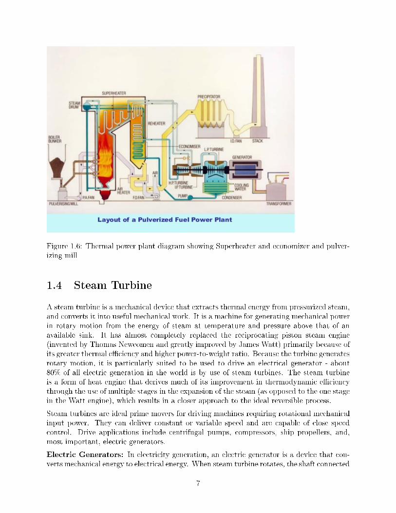
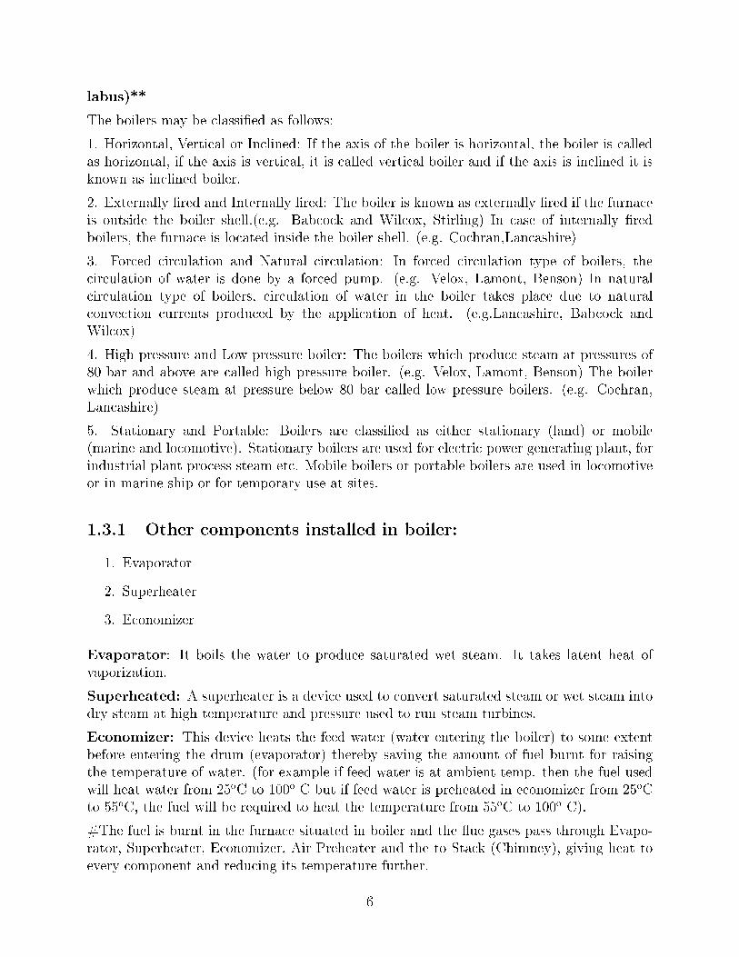
Figure 1.6: Thermal power plant diagram showing Superheater and economizer and pulver-izing mill
1.4 Steam Turbine
A steam turbine is a mechanical device that extracts thermal energy from pressurized steam,and converts it into useful mechanical work. It is a machine for generating mechanical powerin rotary motion from the energy of steam at temperature and pressure above that of anavailable sink. It has almost completely replaced the reciprocating piston steam engine(invented by Thomas Newcomen and greatly improved by James Watt) primarily because ofits greater thermal e�ciency and higher power-to-weight ratio. Because the turbine generatesrotary motion, it is particularly suited to be used to drive an electrical generator - about80% of all electric generation in the world is by use of steam turbines. The steam turbineis a form of heat engine that derives much of its improvement in thermodynamic e�ciencythrough the use of multiple stages in the expansion of the steam (as opposed to the one stagein the Watt engine), which results in a closer approach to the ideal reversible process.
Steam turbines are ideal prime movers for driving machines requiring rotational mechanicalinput power. They can deliver constant or variable speed and are capable of close speedcontrol. Drive applications include centrifugal pumps, compressors, ship propellers, and,most important, electric generators.
Electric Generators: In electricity generation, an electric generator is a device that con-verts mechanical energy to electrical energy. When steam turbine rotates, the shaft connected
7
with the steam turbine rotates the coil inside the generator, thereby producing electricitywhich is then transmitted to the grid. The electricity produced is kept 50 Hz.
Figure 1.7: Steam Turbine
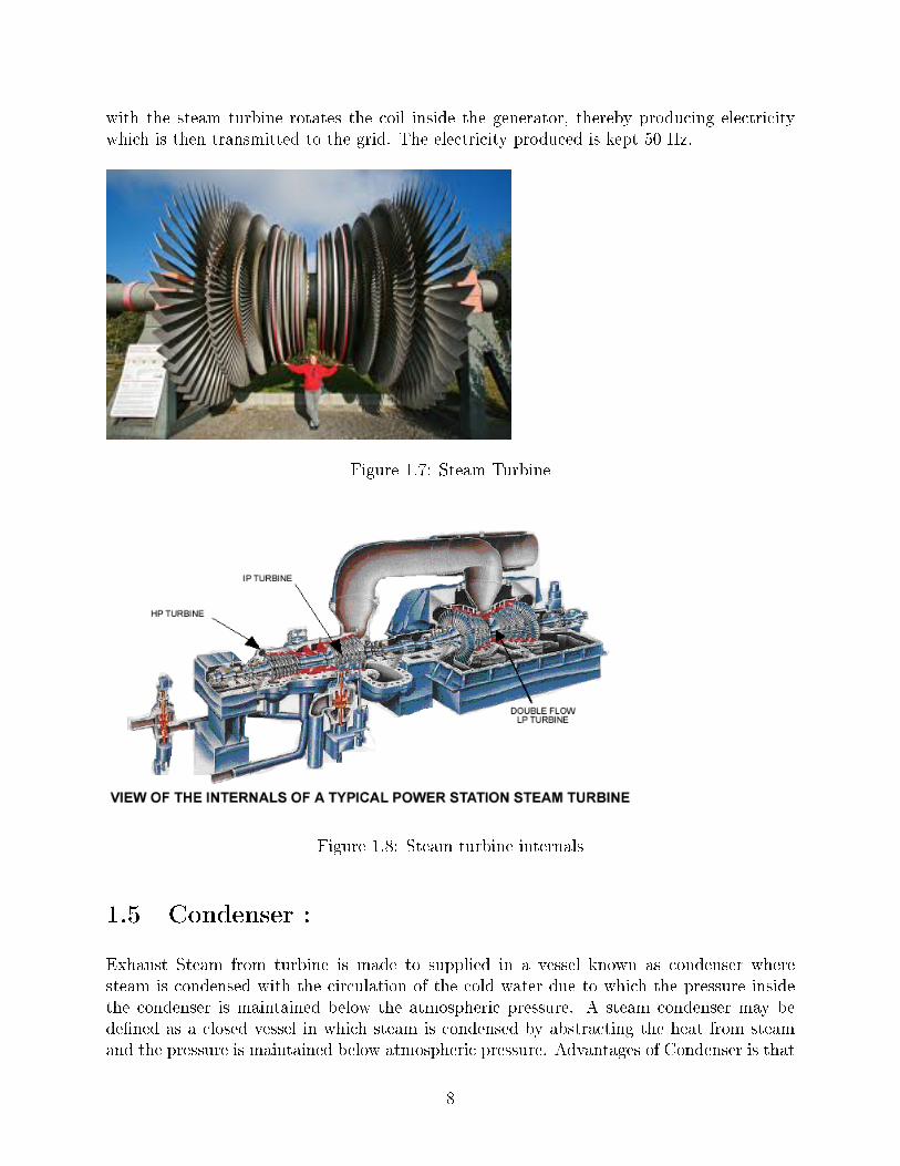
Figure 1.8: Steam turbine internals
1.5 Condenser :
Exhaust Steam from turbine is made to supplied in a vessel known as condenser wheresteam is condensed with the circulation of the cold water due to which the pressure insidethe condenser is maintained below the atmospheric pressure. A steam condenser may bede�ned as a closed vessel in which steam is condensed by abstracting the heat from steamand the pressure is maintained below atmospheric pressure. Advantages of Condenser is that
8
high quality feed water is recovered in the form of condensate which is then supplied backto the steam generator (Boiler) without any further treatment.
The steam that passes through steam turbine looses temperature and pressure as they dowork on turbine. But still as the steam is superheated it is made sure that it does notcondense inside steam turbine (otherwise it might damage blades), so the steam is condensedinside condenser. The steam is passes inside the coils (pipes) of condenser and cold wateris sprayed over the coil. This cold water takes the heat from steam thereby condensing itinside coils. This condensed steam (feed water) is then pumped back into the boiler.
The cold water that gets heated by taking the heat from steam, inside condenser is cooledagain in cooling towers.
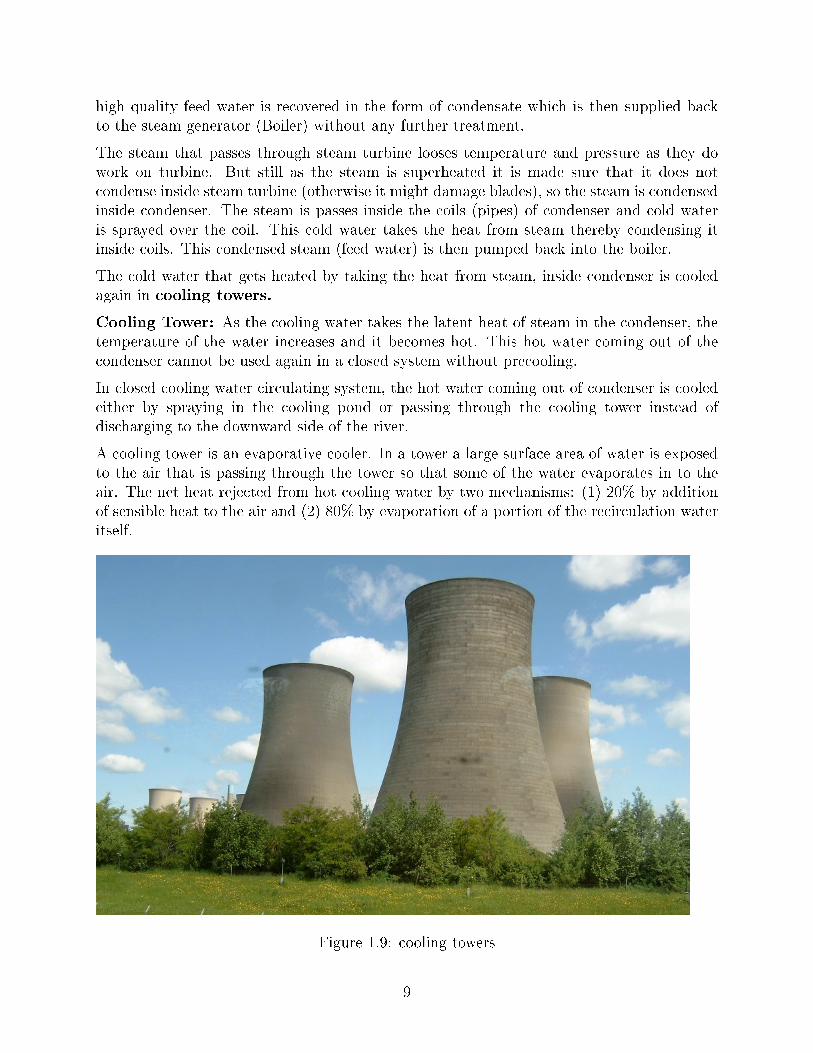
Cooling Tower: As the cooling water takes the latent heat of steam in the condenser, thetemperature of the water increases and it becomes hot. This hot water coming out of thecondenser cannot be used again in a closed system without precooling.
In closed cooling water circulating system, the hot water coming out of condenser is cooledeither by spraying in the cooling pond or passing through the cooling tower instead ofdischarging to the downward side of the river.
A cooling tower is an evaporative cooler. In a tower a large surface area of water is exposedto the air that is passing through the tower so that some of the water evaporates in to theair. The net heat rejected from hot cooling water by two mechanisms: (1) 20% by additionof sensible heat to the air and (2) 80% by evaporation of a portion of the recirculation wateritself.
Figure 1.9: cooling towers
9
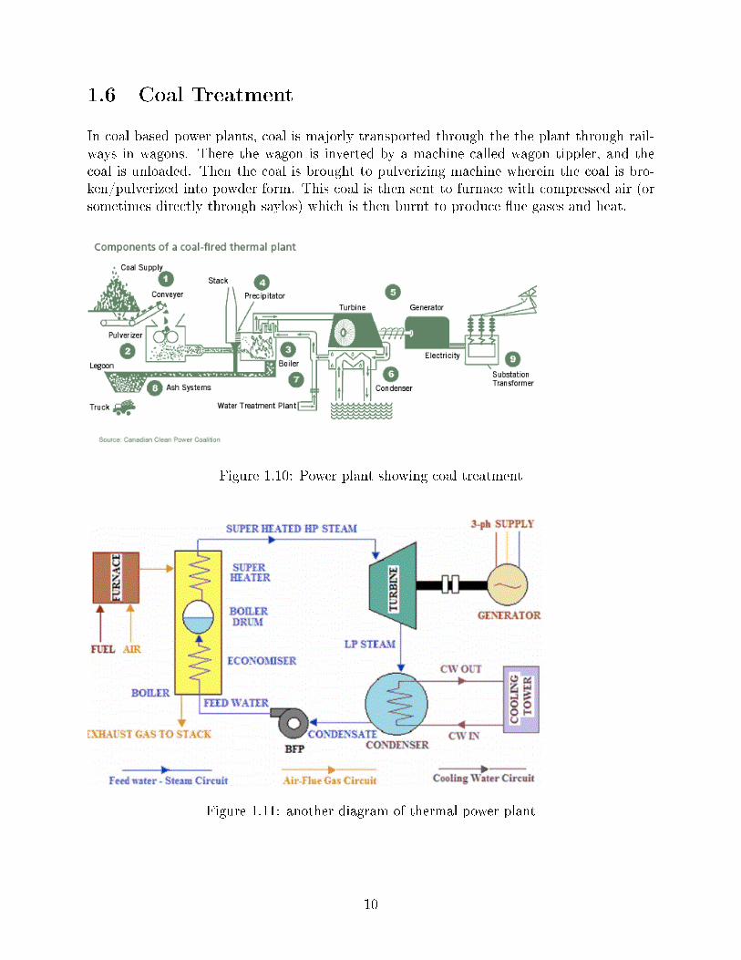
1.6 Coal Treatment
In coal based power plants, coal is majorly transported through the the plant through rail-ways in wagons. There the wagon is inverted by a machine called wagon tippler, and thecoal is unloaded. Then the coal is brought to pulverizing machine wherein the coal is bro-ken/pulverized into powder form. This coal is then sent to furnace with compressed air (orsometimes directly through saylos) which is then burnt to produce �ue gases and heat.
Figure 1.10: Power plant showing coal treatment
Figure 1.11: another diagram of thermal power plant
10
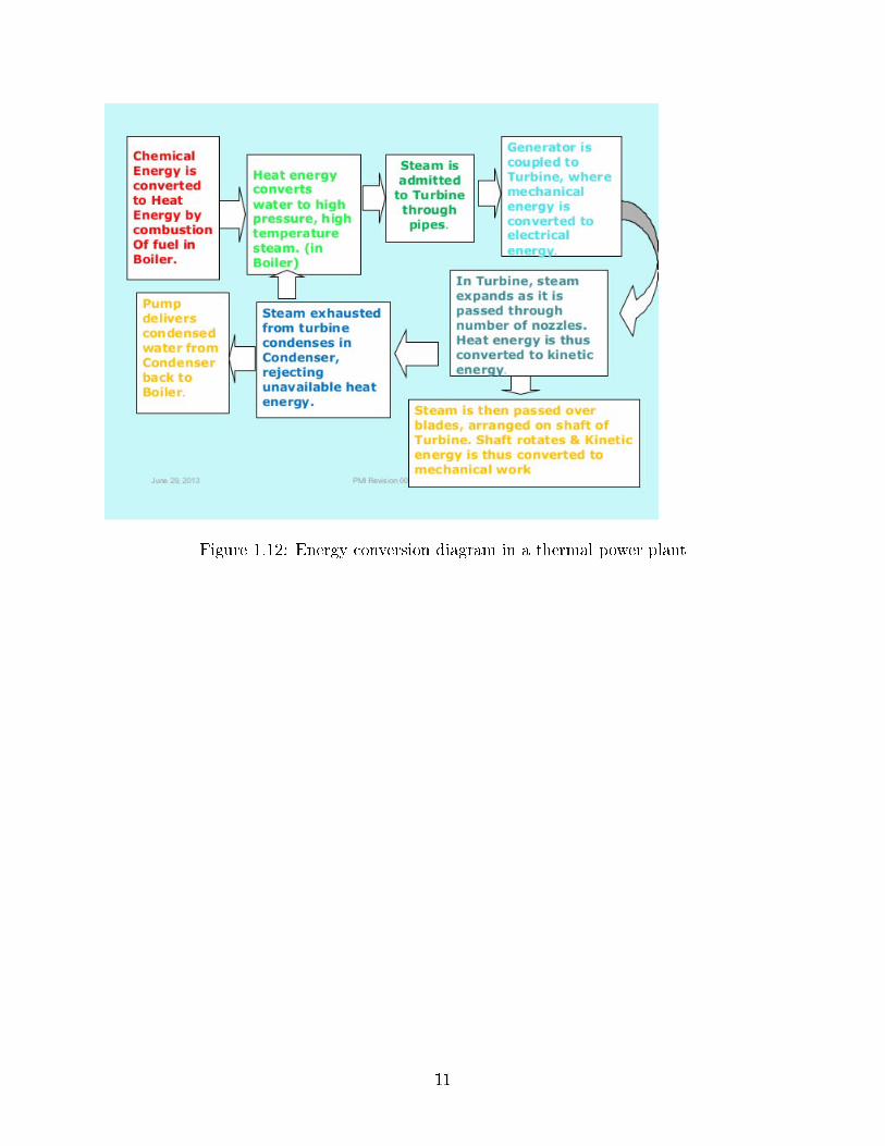
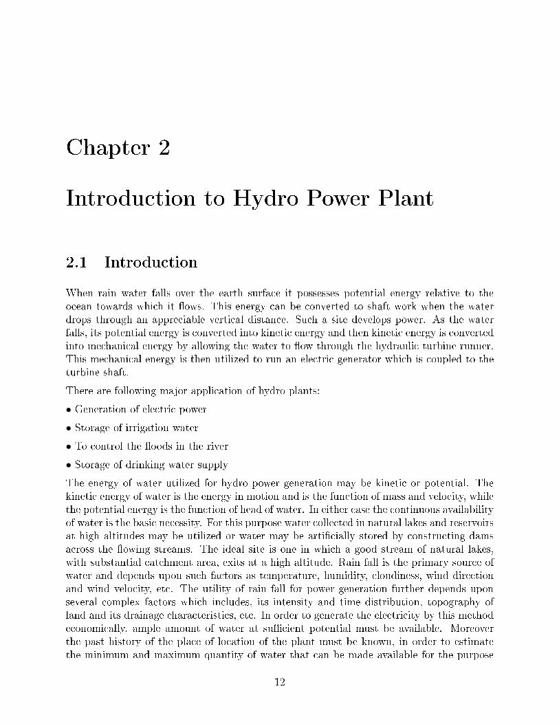
Figure 1.12: Energy conversion diagram in a thermal power plant
11
Chapter 2
Introduction to Hydro Power Plant
2.1 Introduction
When rain water falls over the earth surface it possesses potential energy relative to theocean towards which it �ows. This energy can be converted to shaft work when the waterdrops through an appreciable vertical distance. Such a site develops power. As the waterfalls, its potential energy is converted into kinetic energy and then kinetic energy is convertedinto mechanical energy by allowing the water to �ow through the hydraulic turbine runner.This mechanical energy is then utilized to run an electric generator which is coupled to theturbine shaft.
There are following major application of hydro plants:
• Generation of electric power
• Storage of irrigation water
• To control the �oods in the river
• Storage of drinking water supply
The energy of water utilized for hydro power generation may be kinetic or potential. Thekinetic energy of water is the energy in motion and is the function of mass and velocity, whilethe potential energy is the function of head of water. In either case the continuous availabilityof water is the basic necessity. For this purpose water collected in natural lakes and reservoirsat high altitudes may be utilized or water may be arti�cially stored by constructing damsacross the �owing streams. The ideal site is one in which a good stream of natural lakes,with substantial catchment area, exits at a high altitude. Rain fall is the primary source ofwater and depends upon such factors as temperature, humidity, cloudiness, wind directionand wind velocity, etc. The utility of rain fall for power generation further depends uponseveral complex factors which includes, its intensity and time distribution, topography ofland and its drainage characteristics, etc. In order to generate the electricity by this methodeconomically, ample amount of water at su�cient potential must be available. Moreoverthe past history of the place of location of the plant must be known, in order to estimatethe minimum and maximum quantity of water that can be made available for the purpose
12
of power generation. In storage type hydro projects which content huge quantity of watercollected during heave rain period, is supplied during dry period of the year. Majority ofthe hydro power plants in the world are of this type. The present hydraulic power plant canbe used as an independent power supply unit, but this needs the storage of large amountof water. At the time of low water �ows, the plant will supply the base load only, as themaximum capacity of the station is based on the maximum �ow of water, and hence itbecomes uneconomical. Therefore the present trend is to use hydro electric power plant witha steam plant as an interconnected system. This may reduce the capital cost of hydroelectricpower plant as the size of the reservoir is reduce in this case. Thus in interconnected system,the hydro plant can be used as peak load plant and base load . Of the various primaryenergy sources being used for generation of electric power for public utility supply, hydroelectric power is cheaper as compared with a fuel burning plant . Cost of generation perkWh for hydro station and thermal station are in the ratio 1:3. In hydro electric plant, thecost of generation being free of fuel element.
The main elements of the hydro electric power plant are-
• the catchment area and water reservoir
• dam and intake Inlet water ways
• Power house and equipment
• The tail race
13
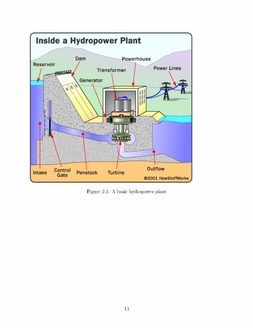
Figure 2.1: A basic hydropower plant
14
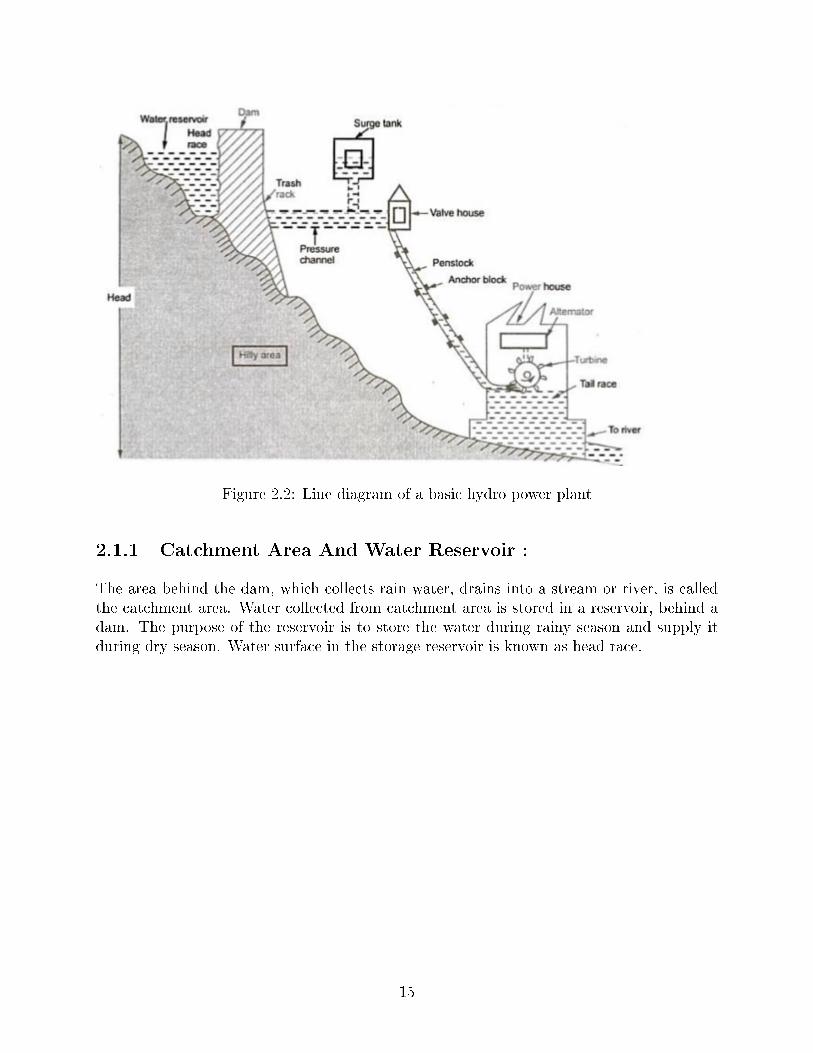
Figure 2.2: Line diagram of a basic hydro power plant
2.1.1 Catchment Area And Water Reservoir :
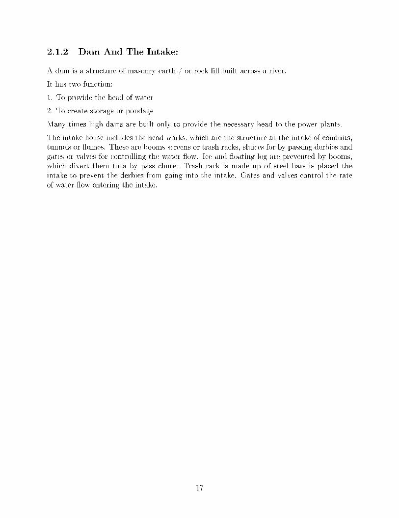
The area behind the dam, which collects rain water, drains into a stream or river, is calledthe catchment area. Water collected from catchment area is stored in a reservoir, behind adam. The purpose of the reservoir is to store the water during rainy season and supply itduring dry season. Water surface in the storage reservoir is known as head race.
15
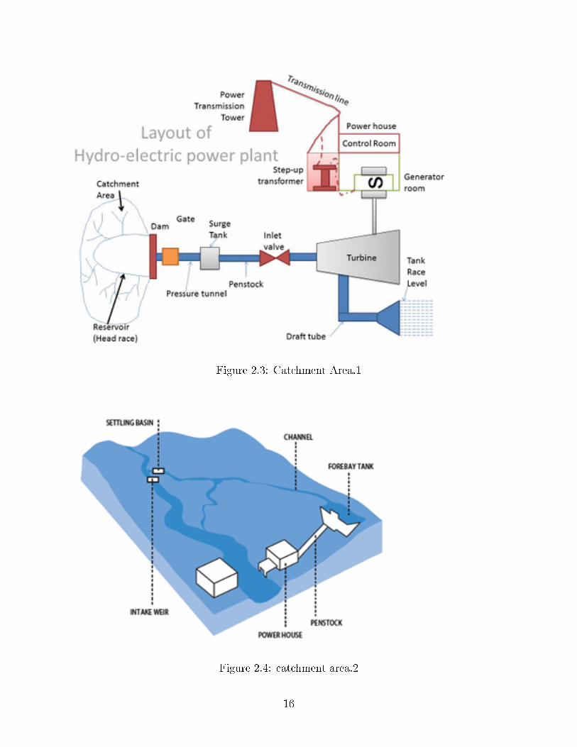
Figure 2.3: Catchment Area.1
Figure 2.4: catchment area.2
16
2.1.2 Dam And The Intake:
A dam is a structure of masonry earth / or rock �ll built across a river.
It has two function:
1. To provide the head of water
2. To create storage or pondage
Many times high dams are built only to provide the necessary head to the power plants.
The intake house includes the head works, which are the structure at the intake of conduits,tunnels or �umes. These are booms screens or trash racks, sluices for by passing derbies andgates or valves for controlling the water �ow. Ice and �oating log are prevented by booms,which divert them to a by pass chute. Trash rack is made up of steel bars is placed theintake to prevent the derbies from going into the intake. Gates and valves control the rateof water �ow entering the intake.
17
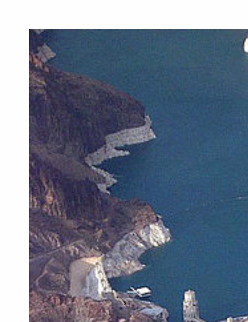
Figure 2.5: Hoover Dam
18
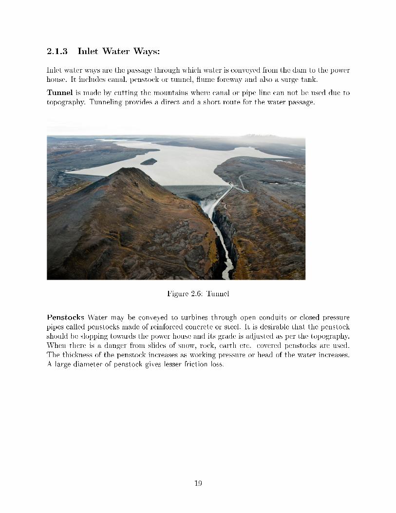
2.1.3 Inlet Water Ways:
Inlet water ways are the passage through which water is conveyed from the dam to the powerhouse. It includes canal, penstock or tunnel, �ume foreway and also a surge tank.
Tunnel is made by cutting the mountains where canal or pipe line can not be used due totopography. Tunneling provides a direct and a short route for the water passage.
Figure 2.6: Tunnel
Penstocks Water may be conveyed to turbines through open conduits or closed pressurepipes called penstocks made of reinforced concrete or steel. It is desirable that the penstockshould be slopping towards the power house and its grade is adjusted as per the topography.When there is a danger from slides of snow, rock, earth etc. covered penstocks are used.The thickness of the penstock increases as working pressure or head of the water increases.A large diameter of penstock gives lesser friction loss.
19
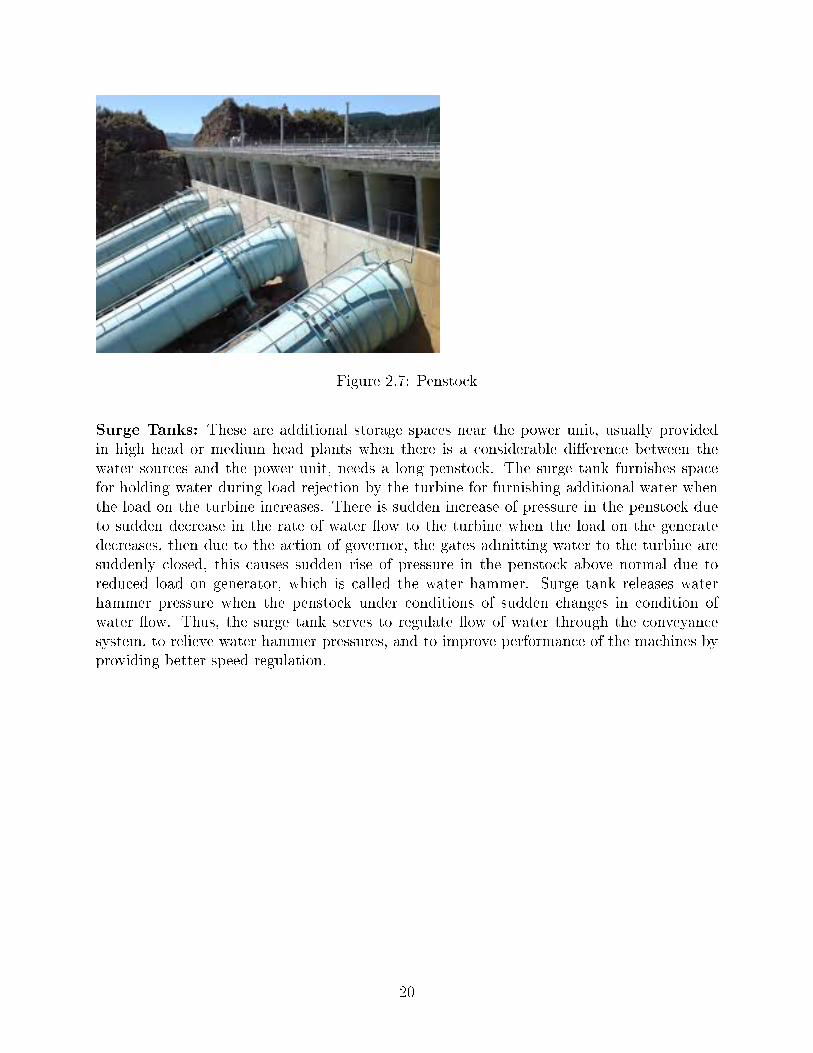
Figure 2.7: Penstock
Surge Tanks: These are additional storage spaces near the power unit, usually providedin high head or medium head plants when there is a considerable di�erence between thewater sources and the power unit, needs a long penstock. The surge tank furnishes spacefor holding water during load rejection by the turbine for furnishing additional water whenthe load on the turbine increases. There is sudden increase of pressure in the penstock dueto sudden decrease in the rate of water �ow to the turbine when the load on the generatedecreases, then due to the action of governor, the gates admitting water to the turbine aresuddenly closed, this causes sudden rise of pressure in the penstock above normal due toreduced load on generator, which is called the water hammer. Surge tank releases waterhammer pressure when the penstock under conditions of sudden changes in condition ofwater �ow. Thus, the surge tank serves to regulate �ow of water through the conveyancesystem, to relieve water hammer pressures, and to improve performance of the machines byproviding better speed regulation.
20
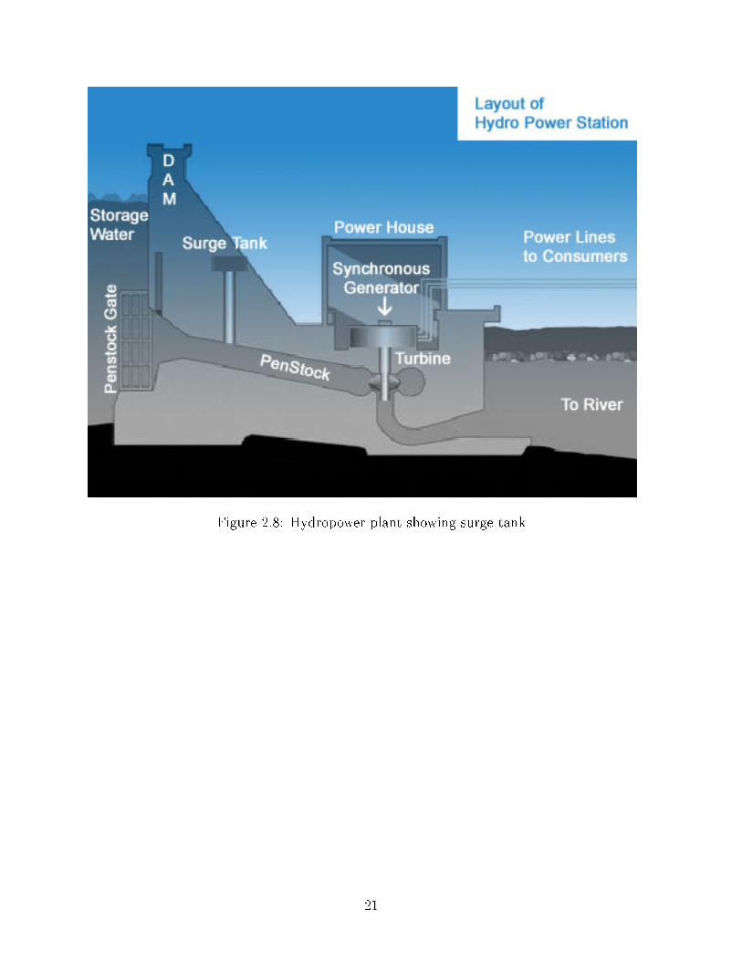
Figure 2.8: Hydropower plant showing surge tank
21
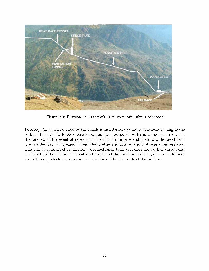
Figure 2.9: Position of surge tank in an mountain inbuilt penstock
Forebay: The water carried by the canals is distributed to various penstocks leading to theturbine, through the forebay, also known as the head pond. water is temporarily stored inthe forebay, in the event of rejection of load by the turbine and there is withdrawal fromit when the load is increased. Thus, the forebay also acts as a sort of regulating reservoir.This can be considered as naturally provided surge tank as it does the work of surge tank.The head pond or foreway is created at the end of the canal by widening it into the form ofa small basin, which can store some water for sudden demands of the turbine.
22
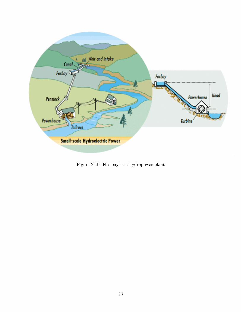
Figure 2.10: Forebay in a hydropower plant
23
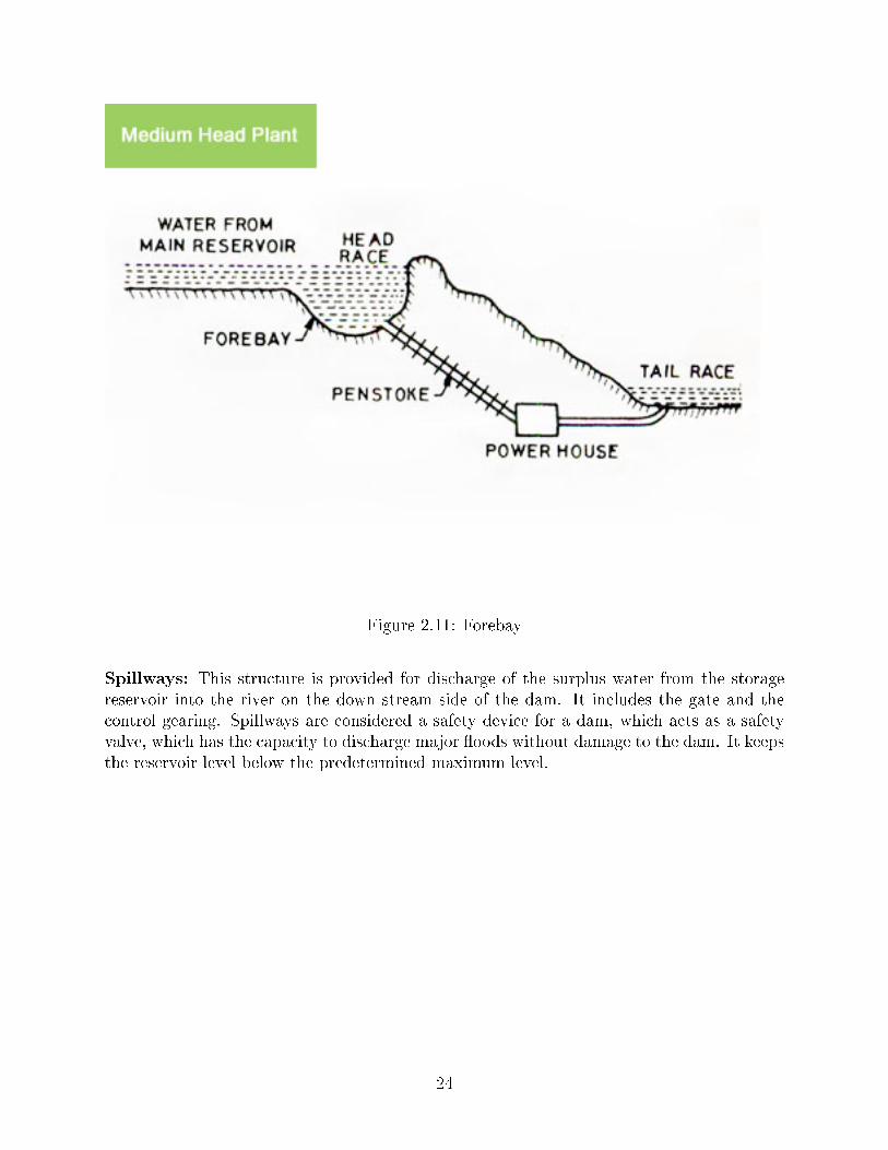
Figure 2.11: Forebay
Spillways: This structure is provided for discharge of the surplus water from the storagereservoir into the river on the down stream side of the dam. It includes the gate and thecontrol gearing. Spillways are considered a safety device for a dam, which acts as a safetyvalve, which has the capacity to discharge major �oods without damage to the dam. It keepsthe reservoir level below the predetermined maximum level.
24
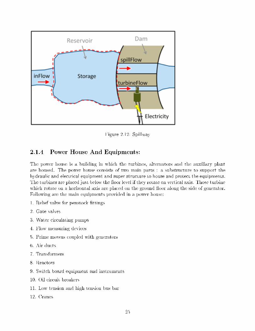
Figure 2.12: Spillway
2.1.4 Power House And Equipments:
The power house is a building in which the turbines, alternators and the auxiliary plantare housed. The power house consists of two main parts : a substructure to support thehydraulic and electrical equipment and super structure to house and protect the equipments.The turbines are placed just below the �oor level if they rotate on vertical axis. Those turbinewhich rotate on a horizontal axis are placed on the ground �oor along the side of generator.Following are the main equipments provided in a power house:
1. Relief valve for penstock �ttings
2. Gate valves
3. Water circulating pumps
4. Flow measuring devices
5. Prime movers coupled with generators
6. Air ducts
7. Transformers
8. Reactors
9. Switch board equipment and instruments
10. Oil circuit breakers
11. Low tension and high tension bus bar
12. Cranes
25
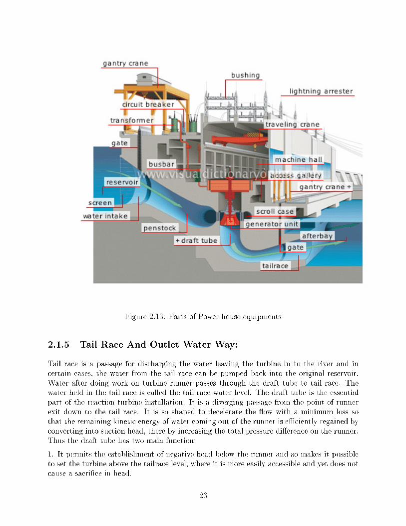
Figure 2.13: Parts of Power house equipments
2.1.5 Tail Race And Outlet Water Way:
Tail race is a passage for discharging the water leaving the turbine in to the river and incertain cases, the water from the tail race can be pumped back into the original reservoir.Water after doing work on turbine runner passes through the draft tube to tail race. Thewater held in the tail race is called the tail race water level. The draft tube is the essentialpart of the reaction turbine installation. It is a diverging passage from the point of runnerexit down to the tail race. It is so shaped to decelerate the �ow with a minimum loss sothat the remaining kinetic energy of water coming out of the runner is e�ciently regained byconverting into suction head, there by increasing the total pressure di�erence on the runner.Thus the draft tube has two main function:
1. It permits the establishment of negative head below the runner and so makes it possibleto set the turbine above the tailrace level, where it is more easily accessible and yet does notcause a sacri�ce in head.
26
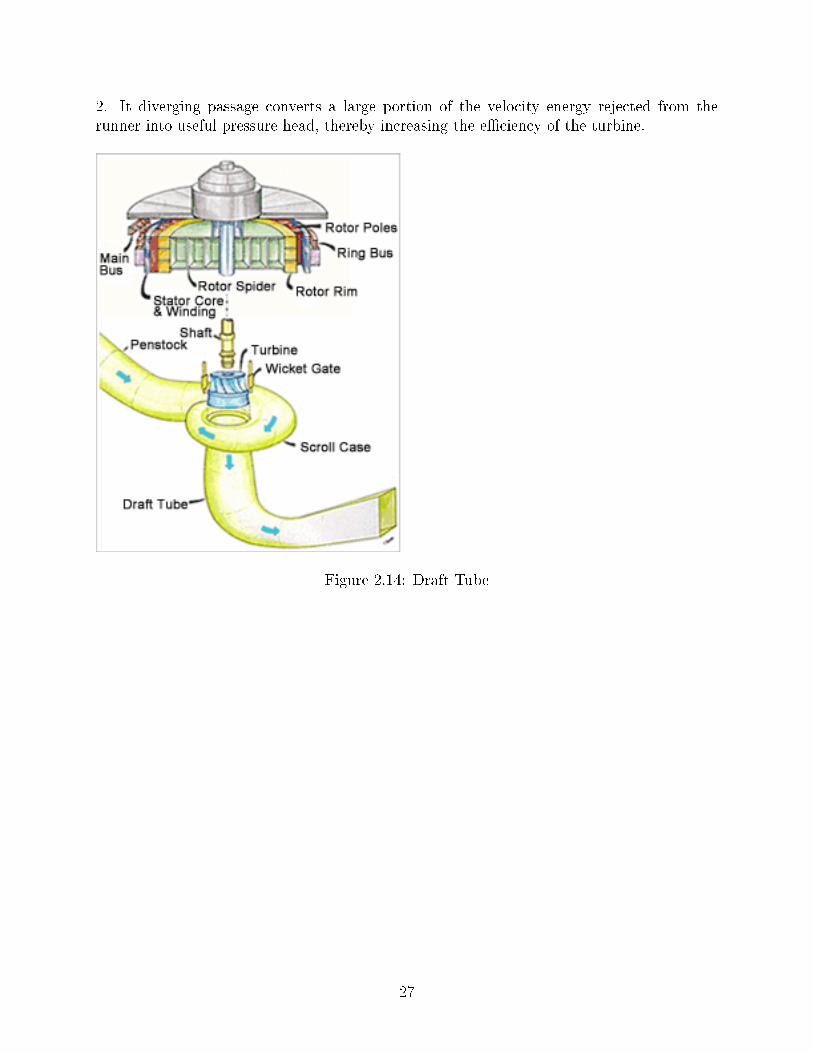
2. It diverging passage converts a large portion of the velocity energy rejected from therunner into useful pressure head, thereby increasing the e�ciency of the turbine.
Figure 2.14: Draft Tube
27
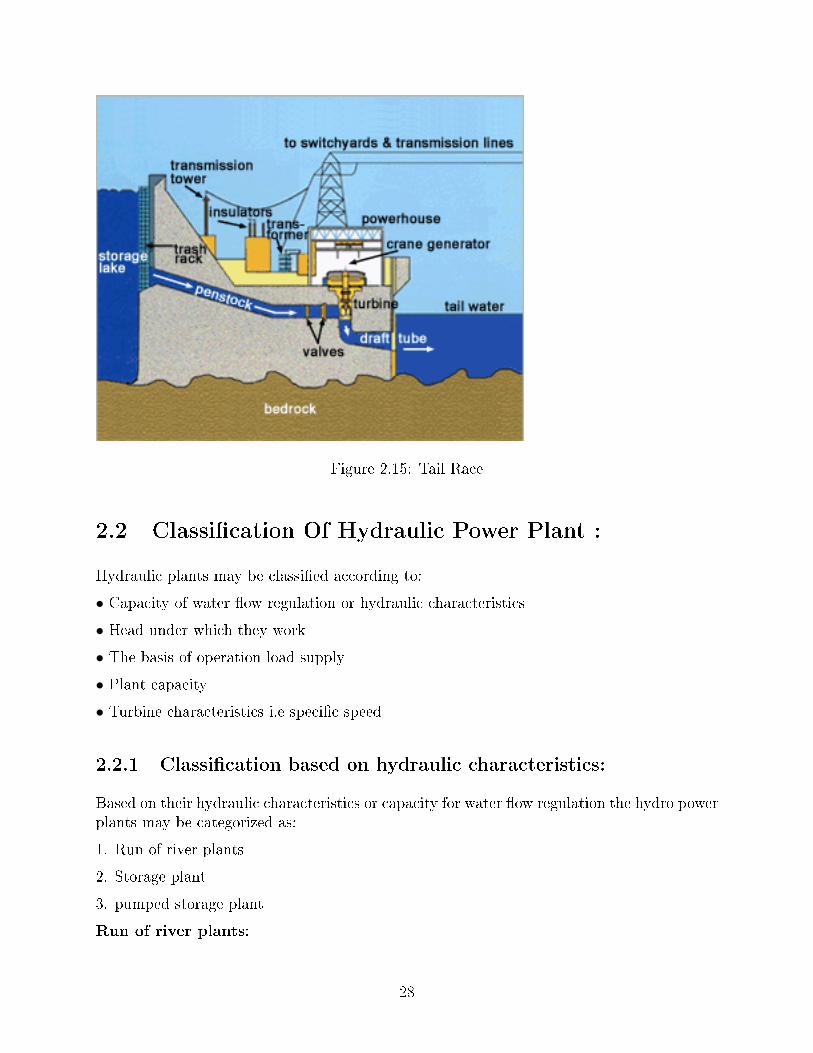
Figure 2.15: Tail Race
2.2 Classi�cation Of Hydraulic Power Plant :
Hydraulic plants may be classi�ed according to:
• Capacity of water �ow regulation or hydraulic characteristics
• Head under which they work
• The basis of operation load supply
• Plant capacity
• Turbine characteristics i.e speci�c speed
2.2.1 Classi�cation based on hydraulic characteristics:
Based on their hydraulic characteristics or capacity for water �ow regulation the hydro powerplants may be categorized as:
1. Run of river plants
2. Storage plant
3. pumped storage plant
Run of river plants:
28
These plants can be classi�ed as either without pondage or with pondage. A run of riverplant without pondage has no control over river �ow and uses the water as it comes. theseplants usually supply peak load. During �oods the tail water level may become excessiverendering the plant inoperative. A run of river plant with pondage may supply base load orpeak load power. At times of high water �ow it may be loaded and during dry seasons itmay be peak loaded.
Storage plants ( reservoir plants):
As the name suggest such plants have reservoir of fairly large size, which usually providesu�cient storage to carry over from wet season to dry season and some times even from oneyear to another. They can there fore supply water at a constant rate which is substantiallyhigher then the minimum natural �ow of the stream. The big dams, certain large lakesusually provide relatively high heads for these power plants. The advantage of this plant isthat the power generated by the plant during dry season will not be a�ected. The storagetakes care of �uctuations of the river supply or that of the load .
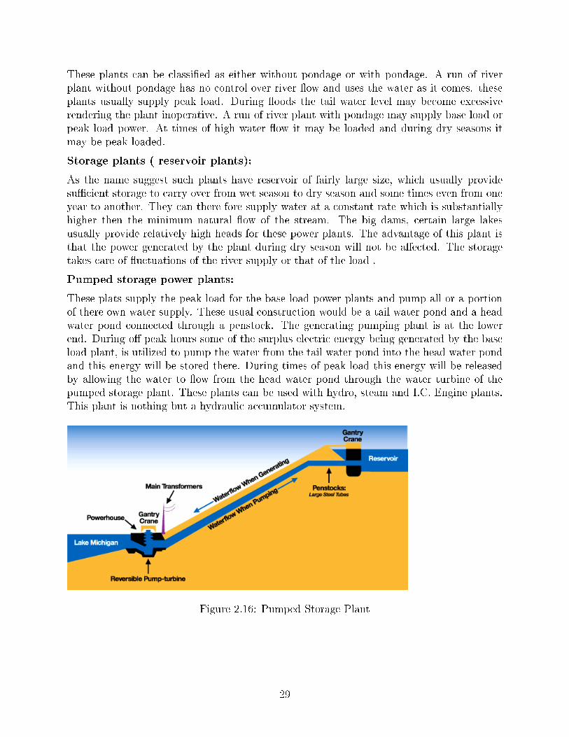
Pumped storage power plants:
These plats supply the peak load for the base load power plants and pump all or a portionof there own water supply. These usual construction would be a tail water pond and a headwater pond connected through a penstock. The generating pumping plant is at the lowerend. During o� peak hours some of the surplus electric energy being generated by the baseload plant, is utilized to pump the water from the tail water pond into the head water pondand this energy will be stored there. During times of peak load this energy will be releasedby allowing the water to �ow from the head water pond through the water turbine of thepumped storage plant. These plants can be used with hydro, steam and I.C. Engine plants.This plant is nothing but a hydraulic accumulator system.
Figure 2.16: Pumped Storage Plant
29
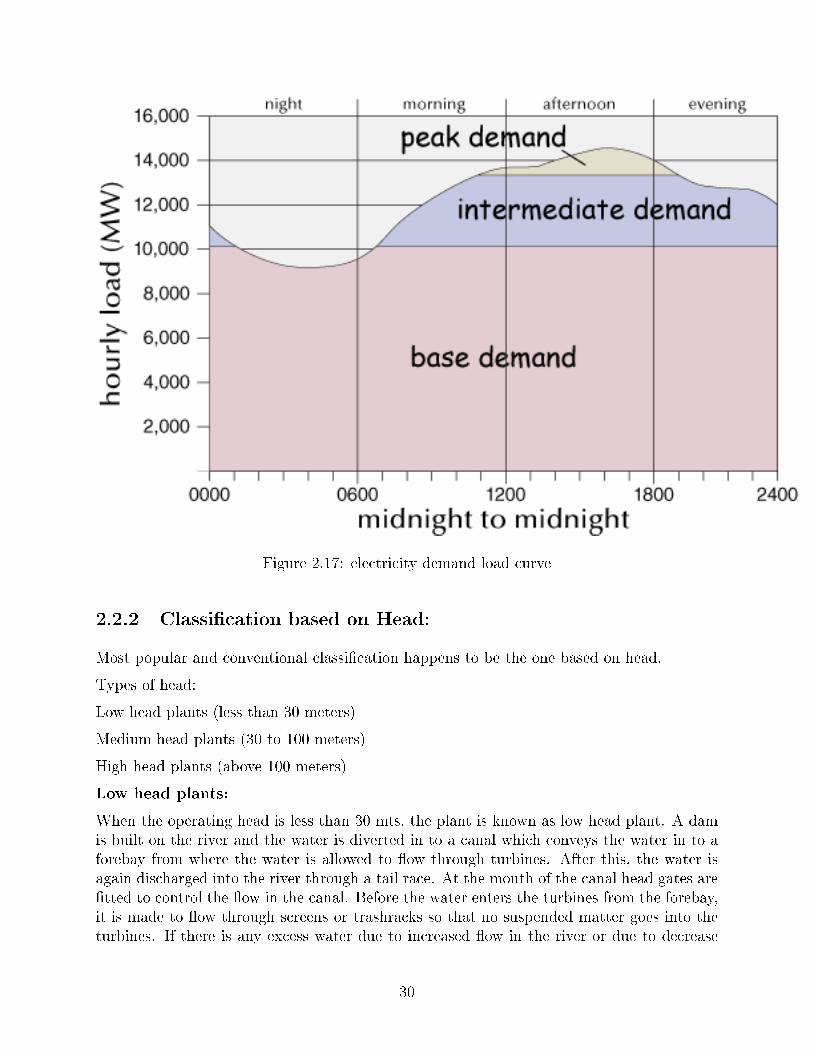
Figure 2.17: electricity demand load curve
2.2.2 Classi�cation based on Head:
Most popular and conventional classi�cation happens to be the one based on head.
Types of head:
Low head plants (less than 30 meters)
Medium head plants (30 to 100 meters)
High head plants (above 100 meters)
Low head plants:
When the operating head is less than 30 mts, the plant is known as low head plant. A damis built on the river and the water is diverted in to a canal which conveys the water in to aforebay from where the water is allowed to �ow through turbines. After this, the water isagain discharged into the river through a tail race. At the mouth of the canal head gates are�tted to control the �ow in the canal. Before the water enters the turbines from the forebay,it is made to �ow through screens or trashracks so that no suspended matter goes into theturbines. If there is any excess water due to increased �ow in the river or due to decrease
30
of load on the plant, it will �ow over the top of the dam or a waste weir can be constructedalong the forebay so that the excess water �ows over it in to the river.
Medium head plants:
If the head of the water available lies between 30 mts to 100 mts, then the power plant iscalled medium head plant. In this type plant the water from the forebay is conveyed to theturbine through penstocks. In this plant the river water is usually tapped o� to a forebayon one bank of the river as in the case of a low head plant. From the forebay the water isthen led to the turbines through penstocks.
High head plants:
If the head of the water available is more then 100 mts, it is called high head plant. Atone end of the reservoir are provided out lets for water leading into forebays or surge tanksand from there to the turbines through penstocks. The surge tank is provided before thevalve house and o�er the tunnel from the head works. The butter�y valves or the sluicetype valves which are electrically driven control the water �ow in the penstock. Gate valvesare used in power house to control the water �ow through the turbines. The Francis turbineand Pelton wheel are the common prime movers in high head plants.
2.2.3 Classi�cation according to the nature of load:
On the basis of load supply, hydro power plants are classi�ed as
1. Base load plant and
2. Peak load plant.
Base load plant:
A plant supplying base load, which is more or less constant, is known as base load plant.Generating units work on almost constant load and their operating e�ciency is usually high.A steam or a diesel power station may share the peak load of such plant. The examples arerun o� river and storage type power plant.
Peak load plants:
If �uctuating peak loads are met by the plant then it is called a peak load plant. Run o� riverplants with pondage and pumped storage plants are necessarily peak load plants. Generallyspeaking hydro power is quite suitable for peak load duration's, due to its quick starting andrelative ease in peaking up load.
2.2.4 Classi�cation based on plant capacity:
Classi�cation of the power plant based on the capacity is as follows:
1. Micro hydel plant (< 5 MW)
2. Medium capacity plant (5 to 100 MW)
3. High capacity plant (100 to 1000 MW)
4. Super plants (> 1000 MW)
31
2.2.5 Classi�cation based on turbine characteristics i.e speed
Classi�cation of hydro power plats based on speci�c speed is as follows:
1. High speci�c speed (300 to 1000)
2. Medium speci�c speed (60 to 300 )
3. Low speci�c speed (10 to 35)
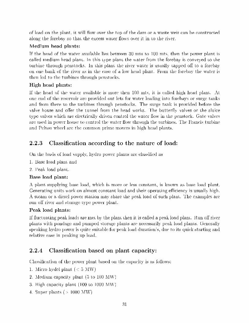
Figure 2.18: Basic Hydro-Turbine
32

Chapter 3
Things you should know:
Datas based on March 2013:
Total installed capacity of power production india : 2,28,721.73 MW
Per capita Energy consumption of India : 879 kWh
33

Chapter 4
Bibliography
All the data and material have been taken from BEE handbooks, Wikipedia and statisticsof govt. of India
34