Embed Size (px)
Citation preview
09 February 2022
A parametric library for the simulation of UIC pneumatic braking system L PUGI M MALVEZZI B ALLOTTA LBANCHI P PRESCIANI - In PROCEEDINGS OF THE INSTITUTION OF MECHANICAL ENGINEERS PART FJOURNAL OF RAIL AND RAPID TRANSIT - ISSN 0954-4097 - STAMPA - 218 part F(2004) pp 117-132[1012430954409041319632]
Original Citation
A parametric library for the simulation of UIC pneumatic braking system
Published version1012430954409041319632
Terms of use
Publisher copyright claim
(Article begins on next page)
La pubblicazione egrave resa disponibile sotto le norme e i termini della licenza di deposito secondo quanto stabilito dallaPolicy per laccesso aperto dellUniversitagrave degli Studi di Firenze (httpswwwsbaunifiituploadpolicy-oa-2016-1pdf)
AvailabilityThis version is available at 2158212608 since 2016-09-08T180040Z
Questa egrave la Versione finale referata (Post printAccepted manuscript) della seguente pubblicazione
FLORERepository istituzionale dellUniversitagrave degli Studi di
Firenze
Open Access
DOI
A parametric library for the simulation of aUnion Internationale des Chemins de Fer (UIC)pneumatic braking system
L Pugi1 M Malvezzi1 B Allotta1 L Banchi1 and P Presciani2
1Dipartimento di Energetica lsquoSergio Steccorsquo Sezione di Meccanica Applicata University of Florence Italy2UTMR Trenitalia SPA Florence Italy
Abstract European trains are equipped with a pneumatic braking system that has to respect severespecifications concerning both performances and safety The pneumatic braking system is composedof hundreds of different pneumatic components that reproduce the prescribed response by a complexlogic of pneumatic and mechanical elements In this paper a tool for a complete simulation of thepneumatic braking system is described it was developed using the MatlabndashSimulink numericalenvironmentThe tool is composed of three different libraries of pneumatic components The first includes the
elementary components such as pipes orifices valves and the reservoir By assembling elementarycomponents an advanced user can build a customized version of general pneumatic components orplants Complex components of general use for railway pneumatic brake such as brake cylindersdistributors pressure transformers and brake valves are available in a second library that can be usedto assemble a customized braking plant for a vehicle The last library is composed of macro-pneumatic subsystems that reproduce the braking system of a typical railway vehicle Many commonplant layouts are reproduced in this library (freight car passenger coaches locomotives etc)The pneumatic brake system of a train can be simulated by assembling in a single MatlabndashSimulink
model the elements of the libraryIn this paper the main features of this numerical tool and the test procedures developed to validate
the software are described Experimental data have been kindly supplied by Trenitalia SPA and theyare referred to several test campaigns managed by Italian railway in order to verify and releaseexisting components of the pneumatic brake
Keywords pneumatic brake simulation computational fluid dynamics (CFD)
NOTATION
a acceleration of the trainA equivalent area of the pipebline equivalent resistance factor introduced
by the line slope and curvesbresethvtrainTHORN equivalent dissipative factor due to
vehiclersquos internal friction andaerodynamics resistances usually apolynomial function of the train travelspeed
B longitudinal braking force exchangedbetween the vehicle and the rail
Belectri equivalent longitudinal forces due to
electric or electromagnetic braking onvehicle i
Bextras external longitudinal forces applied onthe complete train
Cfriction equivalent mechanical damping of thecylinder
CM Mach correction factor of mass flowCq empirical correction factor of mass flowCaA1 CaA2 accelerator chambersCaC chamber of the distributor main deviceCaP pilot chamber of the pressure
transformerCF brake cylinderCFD computational fluid dynamics
The MS was received on 15 April 2003 and was accepted after revisionfor publication on 28 November 2003 Corresponding author Dipartimento di Energetica lsquoSergio SteccorsquoSezione di Meccanica Applicata Universita di Firenze via S Marta 350139 Firenze Italy
117
F01403 IMechE 2004 Proc Instn Mech Engrs Vol 218 Part F J Rail and Rapid Transit
CG brake pipeCP auxiliary brake piped pipe diameterF clamping force exerted by the
pneumatic cylinderFpre-load pre-load of the cylinderh0 total enthalpy per unit massk 1ethRTTHORN (assuming that T frac14 293K)
frac14 1189 e5 s2=m2
Kspring stiffness of the cylinder pre-load springmvehicles
i equivalent inertial mass of vehicle imtrain equivalent inertial mass of the complete
train_mm mass flowM equivalent inertia of the piston and
connected transmission elementsncylinder number of brake cylinders placed on
the vehiclendisc number of brake discs applied to an
axlenpad number of pads applied on a single discnwheelset number of axles braked by a single
cylinderp pressurepd outlet pressurept z discretized pressure at time t and
node zpu inlet pressureP vehicle weight_qq specific thermal power per volume unitR constant for ideal gasRbrake equivalent braking radius of the discRwheel rolling radius of the wheelRe Reynolds numberSA auxiliary reservoirSC command reservoirSP main reservoir (locomotive)T temperatureu air velocityut z discretized velocity at time t and node zvtrain train speedV volumeX piston strokez position along the pipe length
g isentropic exponentZ efficiency of brake riggingl loss factormpad friction factor between pad and discmrail friction factor between rail and wheelr densityt pressure loss in the pipe per unit
lengthtb mechanical transmission rate of rigging
(ratio of the normal pressure on eachbrake pad to the force exerted by eachbrake cylinder)
1 INTRODUCTION THE UNION
INTERNATIONAL DES CHEMINS DE FER
PNEUMATIC RAILWAY BRAKE
The braking system of a train is a complex plant whosedynamic behaviour involves the interaction of pneu-matic mechanical and electronic components Per-formance safety and reliability specifications of thebraking system can really affect many different aspectsof the management of an entire railway system and inparticular
(a) safety(b) traffic intensity(c) maximum commercial velocity management of the
signalling system and(d) length weight number and kind of trailer vehicles
etc
The braking system of every single vehicle interacts withthe complete pneumatic plant of the train Verydemanding specifications prescribed by regulations inforce [1 2] have to be met in order to assure safety andinteroperability between different kinds of vehicle
The braking system of a single vehicle can bemodelled in three main-subsystems (as can be seen inFig 1)
1 Union International des Chemins de Fer (UIC)pneumatic brake A pneumatic plant is used tocontrol the braking system of each vehicle of thetrain The braking command of the driver istransmitted along the train as pressure reference Acomplex system of mechanical and pneumatic com-ponents usually called the UIC pneumatic brake isused to regulate the clamping forces of the brakesfrom this pressure reference The main features ofthis kind of brake are well known among thecommunity of railway researchers
(a) Pneumatic Each actuator or control componentworks with pressurized air
(b) Continuous A single pressure signal propagatesthe brakendashrelease command along the train
(c) Automatic (safe) If the train integrity is inter-rupted the vehicles automatically brake
(d) Inexhaustible The brake is released only if theair reservoirs of the vehicle are filled
2 Mechanical brake on braking surfaces A pneumaticcylinder is used to clamp the sliding surfaces of amechanical brake Disc or block brakes are the mostcommon solutions
3 Anti-skid device The adhesion between the rollingsurfaces of rails and wheels is quite low When thebraking forces are higher than the available adhesionthe rolling surfaces of wheel and rail begin to skidThe anti-skid device is an electro-pneumatic systemable to regulate the clamping force exerted on every
L PUGI M MALVEZZI B ALLOTTA L BANCHI AND P PRESCIANI118
Proc Instn Mech Engrs Vol 218 Part F J Rail and Rapid Transit F01403 IMechE 2004
axle in order to prevent skid and to minimize thespace required to stop the vehicle All vehicles with amaximum speed above certain levels are equippedwith anti-skid devices and in particular high-speedtrains
In this work the present authors have focused theirattention on the first two subsystems neglecting theeffects of anti-skid device This approach may be usefulin order to simulate braking performances of a trainwith optimal adhesion conditions when this kind ofdevice does not intervene
The dynamic behaviour of the pneumatic plant maydelay the propagation of the brakingndashrelease commandalong the train This delay could cause heavy long-itudinal loads along the train which may cause damageor even derailment In order to avoid this dangerouscondition the pneumatic components of the plant areoften regulated with complex systems of calibratedorifices springs and reservoirs
The optimization of this system is quite difficult andso a numerical tool can really contribute to reducetesting and development costs Also the complexity of
the resulting pneumatic plant may introduce undesiredor unpredictable responses of the systems such asuncontrolled partial brake or release the numericalsimulation may help this to be understood
The paper is organized as follows Section 2describes the main features of a pneumatic plant Insection 3 the developed sofware is described and inparticular the main blocks contained in the toolbox areshown Section 4 presents a first validation of themodel obtained by comparing the simulation resultswith the experimental data In section 5 the conclusionsof the work and a brief description of possibleimprovements are presented
2 PNEUMATIC PLANT DESCRIPTION
21 General layout
Figure 2 shows the simplified scheme of the UICpneumatic brake [3] The brake pipe CG (1) links allthe pneumatic circuits of the train through a system of
Fig 1 Simplified scheme of the braking system of a modern train
A PARAMETRIC LIBRARY FOR THE SIMULATION OF A UIC PNEUMATIC BRAKING SYSTEM 119
F01403 IMechE 2004 Proc Instn Mech Engrs Vol 218 Part F J Rail and Rapid Transit
cocks (2) and coupled hoses (3) which are used toconnect the vehicles The distributor (4) is connected tothe CG
The distributor evaluates the difference between theconstant pressure of the command reservoir SC (6) andthe reference signal of CG If the pressure of the brakepipe is lower than the SC pressure the distributorregulates the pressure of the braking cylinder CF (7)with a pressure which is approximately proportional tothe pressure drop of the brake pipe CG feeds thedistributor with pressurized air which is stored in theauxiliary reservoir SA (5) If the CF pressure rises abovethe desired level the distributor connects the cylinderwith the atmosphere
SA and SC are fed by the pneumatic brake during therelease phase of the brake in this phase the pressure ofthe brake pipe returns to its nominal value Thecomplete plant is fed by a compressor (9) and a mainreservoir SP (10) placed on the locomotive Thereference pressure signal of the brake pipe is controlledby the driverrsquos brake valve (11) placed on thelocomotive
In order to obtain a shorter brake release phase anauxiliary pressurized pipe may be directly connected tothe reservoir SA this second pipe CP (1) is directly fedby the main reservoir Figure 3 shows a more detailedscheme of a pneumatic brake with an auxiliary pipe Thedistributor is a totally pneumatic control element with avery complex internal structure
In this study attention was focused on a particularkind of distributor the Westinghouse U distributorwhich is quite common on Italian trains Figure 4 showsa detailed scheme of this type of distributor
22 Westinghouse U distributor
The Westinghouse U distributor it is composed of fivemain subsystems
1 Main device This is composed of three pistons withthe aim of regulating the air pressure inside the brakecylinders in order to satisfy the reference pressuresignal of the brake pipe CG
Fig 2 Simplified pneumatic layout of the UIC brake
Fig 3 Pneumatic brake scheme with the auxiliary pipe
L PUGI M MALVEZZI B ALLOTTA L BANCHI AND P PRESCIANI120
Proc Instn Mech Engrs Vol 218 Part F J Rail and Rapid Transit F01403 IMechE 2004
2 Command reservoir filling device and first chargeaccelerating device These two devices are devotedto regulating the correct and faster feeding of thecommand reservoir in order to assure correctintervention of the distributor
3 First phase device This pneumatic device introduces anon-linear correction of the distributor response Forlow braking pressures (lower than 16 bar) thefeeding of the cylinder is faster Also a system ofauxiliary capacities is used to accelerate the propaga-tion of the pressure drop signal along the brake pipeWhen high braking pressures occur this deviceintroduces an upper saturation of cylinder pressurecorresponding to a value of 485 bar
4 Auxiliary reservoir filling device This device isdesigned in order to assure a faster and safer feedingof the auxiliary reservoir SA When the pressure dropbetween SA and the brake pipe is higher than 04 barthis device assures fast recharge of the auxiliaryreservoir
5 Freightndashpassenger device Regulation in force estab-lishes that passenger coaches and freight cars musthave different braking performances This is due toseveral technical reasons which are well knownamong the community of railway researchers
(a) different train lengths (freight trains may be muchlonger than passenger trains)
(b) different commercial speeds (passenger trains arecharacterized by higher speeds)
(c) the high weight variability of freight trains withinanimate loads that are often more sensitive toacceleration variations
(d) different braking performances
For these reasons freight train brake systems havevery different performances from passenger trainbrake systems This pneumatic device is used toobtain a different dynamic response of the distributoraccording to the kind of vehicle (freight or passenger)
3 MATHEMATICAL MODELLING
A library of pneumatic models for the MatlabndashSimulinkenvironment has been developed in order to simulate thedynamic behaviour of the UIC railway brake Thislibrary is composed of three main subsets of models
1 Elementary components A set of models is used thatis able to simulate simple physical problems such as
Fig 4 Detailed pneumatic scheme of the Westinghouse U distributor
A PARAMETRIC LIBRARY FOR THE SIMULATION OF A UIC PNEUMATIC BRAKING SYSTEM 121
F01403 IMechE 2004 Proc Instn Mech Engrs Vol 218 Part F J Rail and Rapid Transit
pressure propagation on a constant-section pipe orthe flux through an orifice These components aredefined as elementary because almost all the compo-nents of a pneumatic plant can be built by assemblingthese simple blocks
2 Complex components Brake cylinders distributorspressure transformer brake valves and other com-plex devices are defined as an array of elementarycomponents whose dynamic interaction is controlledby a finite state machine modelled with Stateflow aMatlabndashSimulink dedicated tool
3 Full vehicle plant The pneumatic plant of a singlevehicle (passenger coach freight car locomotiveetc) is modelled by assembling lsquoelementaryrsquo andlsquocomplexrsquo pneumatic components By assemblingdifferent models of lsquovehiclesrsquo the user can easilybuild up the complete pneumatic plant of a trainThe subsystem also includes a simple model of thelongitudinal dynamic of the train according to theapplied braking forces
31 Elementary components
This library is mainly composed of five components
1 Pipe calculus node Long pipes such as CG arediscretized using the finite difference technique with asequence of calculus nodes
2 Pipe capacity node This node is used as a fitting or aconnector to link two or more components of theplant
3 Orifice This simple element is used to modelcalibrated holes or valves (treated as orifices with avariable area)
4 Chambers This component is used for a simple andfast calculation of the capacity elements placed insidecomplex pneumo-logic elements such as distributors
5 Terminators and modified blocks Terminator blocksare used to introduce boundary conditions of theplant such as imposed pressures or mass flows Othercomponents can be modelled as modified versions ofthe previously described blocks For example in thecylinder subsystem some customized elements havebeen inserted in order to model a continuouslyvariable capacity
311 Pipe calculus node
A pipe is modelled as a constant-area one-dimensionalduct Air is assumed to be an ideal gas all thetransformations are isothermal ethTfrac14 293KTHORN and pres-sure loss are modelled according to DarcyndashWeisbachformulation This approach is quite common in theliterature [4ndash8] The flow cannot be modelled asadiabatic due to the high irreversibility of thermo-dynamic transformations and the large thermal
exchange surfaces involved The polytropic tranforma-tion that represents a better approximation of thephenomenon is then isothermal This model representsa good compromise between computational load andreliability of simulation results
The following equations can be written in order todescribe the dynamics of the flow in the pipe Theconservation of the mass in the tube can be expressed bymeans of the differential equation
qrqt
thorn qethruTHORNqz
frac14 0 eth1THORN
while the equilibrium balance can be written as
rdu
dtfrac14 qp
qz t eth2THORN
The total enthalpy balance can be expressed as
rdh0
dtfrac14 qp
qtthorn _qq eth3THORN
The fluid involved in the flow is air and then thefollowing relation holds
p frac14 rRT eth4THORN
The pressure loss in the pipe is calculated by means ofthe expression
t frac14 lrd
u2
2eth5THORN
where l is calculated according to references [4] to [6]as a function of the Reynolds number Re using theexpressions
Re lt 2000 l frac14 64
Re
2000 lt Re lt 4000 l frac14 00027
Re0222
Re gt 4000 l frac14 0316
Re025
In this analysis the enthalphy balance (4) was notconsidered and isothermal conditions were supposed Inthis case the flow can be described by the differenceequations
qpqt
frac14 uqpqz
pquqz
eth6aTHORN
quqt
frac14 uquqz
1
kp
qpqz
ld
u2
2eth6bTHORN
These equations were solved using a numericalapproach The pipe was divided into a series of calculusnodes The derivative terms in the differential equation
L PUGI M MALVEZZI B ALLOTTA L BANCHI AND P PRESCIANI122
Proc Instn Mech Engrs Vol 218 Part F J Rail and Rapid Transit F01403 IMechE 2004
were approximated as
qpt zqt
frac14 ptthornDt z pt z
Dtqpt zqz
frac14 pt z pt zDz
Dzqut zqz
frac14 ut z ut zDz
Dzqut zqt
frac14 utthornDt z ut z
Dteth6cTHORN
Then from equations (6a) and (6b) the followingdifference equations are obtained
PtthornDt z frac14 pt z 1 kDtDz
ethut z ut zDzTHORN
ut zDtDz
ethpt z pt zDzTHORN eth7aTHORN
utthornDt z frac14 ut z 1 DtDz
ethut zthornDz ut zTHORN
DtDz
ethpt zthornDz pt zTHORNkpt z
ldDt
u2t z2
eth7bTHORN
312 Pipe capacity node
The pipe capacity node is modelled as a constantisothermal volume with various inlet and outlet massflows Imposing mass conservation and neglectingkinetic energy the following equation is obtained
qqt
ethVc
rc dv
frac14Xnifrac141
pethdiTHORN2
4riut i
ut i gt 0 ) ethinlet flowTHORN eth8THORN
In this calculus node the flows are characterized by thesame temperature (due to the isothermal assumption)and locally have the same pressure then the sameconstant density is assumed for every flow ethri frac14 rcTHORNAccording to these hypotheses the mass balance can besimplified as
qpcqt
frac14 ppc4Vc
Xnifrac141
d2i ut i eth9THORN
Vc represents the local equivalent capacity of the pipeUsually because of the dimension of the discretizationgrid its value is small In other words the pipe capacitynode is a fictitious numerical solution to model fittingsand connector by imposing a simple mass balance whileVc models the damping in the pressure drop propaga-tion due to the fluid compressibility
Lumped pressure losses associated with the connec-tors are evaluated in the pipe calculus nodes linked tothe pipe capacity node Equation (9) is then discretizedfollowing the finite differences approach giving theequation
ptthornDt c frac14 pt c 1thorn pDt4Vc
Xnifrac141
d2i ut i
eth10THORN
313 Orifice
Calibrated holes or valves are modelled using the orificecomponent The block orifice calculates the mass flowusing well-known empirical correlations [9ndash11] as afunction of inlet pu and outlet pressure pd
_mm frac14 ACqCMpuffiffiffiffiffiffiTu
p eth11THORN
where CM is a correction factor that is calculated froman isentropic approach to the problem (following theprocedure described in the ISO 6358 1989 regulation[12])
CM frac14
ffiffiffiffiffiffiffiffiffiffiffiffiffiffiffiffiffiffi2g
Rethg 1THORN
s ffiffiffiffiffiffiffiffiffiffiffiffiffiffiffiffiffiffiffiffiffiffiffiffiffiffiffiffiffiffiffiffiffiffiffiffiffiffiffiffiffiffiffiffiffiffipd
pu
2=g
pd
pu
ethgthorn1THORN=g
ssubsonic
ffiffiffiffiffiffiffiffiffiffiffiffiffiffiffiffiffiffiffiffiffiffiffiffiffiffiffiffiffiffiffiffiffiffiffiffiffiffiffiffiffigR
2
gthorn 1
ethgthorn1THORN=ethg1THORNs
frac14ffiffiffiffiffiffiffiffiffiffiffiffiffiffiffiffiffiffi
2gRethgthorn 1THORN
s2
gthorn 1
1=ethg1THORN supersonic
eth12THORN
8gtgtgtgtgtgtgtgtgtgtgtgtgtltgtgtgtgtgtgtgtgtgtgtgtgtgt
However the real flow is not necessarily isentropic (dueto the high irreversibility of the thermodynamicprocesses) therefore an empirical correction factor Cq
evaluated according to the Perry correlation is intro-duced
Cq frac14 08414 01002pd
pu
thorn 08415
pd
pu
2
39pd
pu
3
thorn 46001pd
pu
4
16827pd
pu
5
eth13THORN
The orifice area can be changed in order to simulate thebehaviour of a valve
There are no derivative terms in equation (11) and sothe mass flow can be directly computed without anykind of discretization from the values of inlet and outletpressures From a physical point of view an orificeblock represents a lumped pressure drop associated witha part of the modelled pneumatic component
A PARAMETRIC LIBRARY FOR THE SIMULATION OF A UIC PNEUMATIC BRAKING SYSTEM 123
F01403 IMechE 2004 Proc Instn Mech Engrs Vol 218 Part F J Rail and Rapid Transit
314 Chamber
Inlet and outlet pressures of orifice elements areevaluated using chambers A chamber is a fictitiousvolume capacity which is introduced in order tocalculate inlet and outlet pressures of the connectedorifice blocks Chambers components evaluate thepressure inside a known volume by means of a simplemass balance of inlet and outlet flows
qqt
ethVc
rc dv
frac14Xnifrac141
_mmt i
Air is modelled as an ideal gas and the process isassumed to be isothermal then the following relationholds
qqt
kpcVceth THORN frac14Xnifrac141
_mmt i
from which the pressure derivative term can beevaluated
qpcqt
frac14Pn
ifrac141 _mmt i
kVceth14THORN
The following difference equation can be obtained bydiscretizing equation (14)
ptthornDt c frac14 pt c thornDtkVc
Xnifrac141
_mmt i eth15THORN
Equations (14) and (15) are quite similar to the pipecapacity node equations (9) and (10) However the waysin which the chamber and pipe capacity node equationsare used are quite different the capacity Vc parameter ofthe chamber elements is not necessarily small since itrepresents the equivalent lumped capacity of themodelled part (such as a reservoir) For complexcomponents such as distributors inaccuracy in thesimulation results may be introduced by unmodelledphenomena due to the geometrical layout of thecomponents or to secondary elements that have beenneglected Then the value of the Vc parameter must betuned in order improve the correspondence to experi-mental data
32 Complex components
This library is composed of several different submodelsthat are able to reproduce the pneumatic behaviour ofthe brake plant components
1 Cylinder This model reproduces the dynamicresponse of the brake cylinder and calculates theresulting clamping forces according the mechanicalbrake layout (number of discs leverage ratio andefficiency etc) The equivalent capacity of the
cylinder is modelled by means of a special chamberwith a continuous volume Vc
2 Brake valves Models of the valves are used toregulate the pressure of the brake pipe CG
3 Distributor Complex pneumatic-logic componentsare used to regulate the clamping pressure of brakecylinders from the reference signal of pipe CG
4 Pipes and connectors Arrays of pipe calculus nodesand pipe capacity nodes are available in order tosimulate pipes and common kind of connectors(three-way T-connectors cross connectors coupledhoses between different diameters etc)
5 Other components Several minor components areavailable as lightly modified existing models
321 Cylinder
The brake cylinder (whose section is shown in Fig 5) ismodelled as a special chamber with a variable volumewhose value depends on the piston stroke X Pneumaticbehaviour is evaluated with a simple mass balance
qqt
ethVC
rc dv
frac14 _mmt i
By assuming an ideal gas with isothermal conditions thisequation can be rewritten as
qqt
ethkpcVcTHORN frac14 _mmt i
qqt
frac12kpcAXethtTHORN frac14 _mmt i
qqt
frac12 pcXethtTHORN frac14 _mmt i
Ak
eth16THORN
Equations (16) can be integrated according to the initialcondition P0 when the cylinder stroke is equal to X0 Thepressure p of the cylinder can be then evaluated as afunction of the mass flow and the piston stroke XethtTHORN
pcethtTHORN frac141
XethtTHORN X0p0 thorn1
kA
etht0
_mmethtTHORN dt
eth17THORN
The piston dynamics and the force exerted by theactuator are calculated using different relations thatdepends on the value of piston stroke At the beginningof the braking phase there is no contact between padand disc and so the piston motion is described by theequation
M euroXXethtTHORN frac14 Afrac12 pcethtTHORN pa Cfriction_XXethtTHORN
KspringXethtTHORN Fpre-load eth18THORN
When the piston reaches the position Xcontact which
L PUGI M MALVEZZI B ALLOTTA L BANCHI AND P PRESCIANI124
Proc Instn Mech Engrs Vol 218 Part F J Rail and Rapid Transit F01403 IMechE 2004
corresponds to the contact mate of pad and disc themotion suddenly stops As this second condition isachieved the force F exerted by the actuator is evaluatedaccording to the static equilibrium condition
FethtTHORN frac14 Afrac12 pcethtTHORN pa KspringXcontact Fpre-load eth19THORN
This approach introduces an error during pistondeceleration transients because the contribution of theinertial term M euroXXethtTHORN disappears in the transition betweenequation (18) and equation (19) and there is adiscontinuity in the equation However its effect onthe simulation results can be considered to be negligible
322 Brake valve
A driverrsquos brake valve is used to regulate the pressure ofthe brake pipe CG Several kinds of valve are modelledin the block library developed In this work the authorshave focused their attention on the self-regulating cockThis cock has six working positions that corresponds todifferent pressures of the brake pipe
1 Rapid charging position The brake pipe is over-fedwith a pressure that is higher than the nominal value(65 bar this value is given by the sum of the nominalvalue defined in the UIC 540-03 regulation [13] andthe atmospheric pressure) in order to acceleraterelease of the brake
2 Filling position The brake pipe pressure is regulatedat the nominal pressure (6 bars)
3 Low service braking A light pressure drop (55 bars)is imposed on the brake pipe
4 Maximum service braking The pressure is regulatedto 45 bars Full service braking is the maximumbraking power that is achieved with this pressure
5 Full service braking Some special vehicles andlocomotives may have an extra braking level bylowering the pressure to 39 bars
6 Emergency (rapid) braking To obtain a fasterresponse in emergency situation the brake pipe isconnected directly to the atmosphere
This device is modelled with a lumped capacity of thebrake valve CaR and its scheme is shown in Fig 6
Fig 5 Brake cylinder
Fig 6 Simplified pneumatic scheme of the driverrsquos brakevalve
A PARAMETRIC LIBRARY FOR THE SIMULATION OF A UIC PNEUMATIC BRAKING SYSTEM 125
F01403 IMechE 2004 Proc Instn Mech Engrs Vol 218 Part F J Rail and Rapid Transit
1 The CaR element is connected by an orifice to aterminator block PA which sets an outlet pressureequal to the atmospheric pressure When emergencybraking is activated this orifice is open and the aircan leave the pipe CaR is also connected to threechambers elements
2 SP represents the lumped capacity of the mainreservoir of the locomotive that is fed by acompressor
3 BaR is the equivalent capacity of the equalizingreservoir which is connected through a calibratedhole to atmosphere
4 CG is a chamber element used to connect the valve tothe brake pipe
Orifice equivalent diameters are dynamically regu-lated by a MatlabndashSimulink state-flow chart thatsimulates the behaviour of the valve according to theselected working position
323 Distributor
The pneumatic behaviour of the distributor is modelledas a lumped system of chambers (lumped capacity) andorifices (lumped pressure drop) In Figs 7 and 8 thesimplified schemes adopted to model the WestinghouseU distributor are shown The flow through some orificeelements is regulated by a state-flow chart [14ndash16] whichis able to reproduce the logic of this device
The distributor model is connected to the pipe blockthrough a T connector simulated by a fictitious pipecapacity node Air flows through the main chamberCaA of the distributor In addition the acceleratorcapacities CaA1 and CaA2 are modelled in order tosimulate how this device really speeds up pressure droppropagation along the brake pipe
CaA is connected to the equivalent capacities ofauxiliary (SA) and command (SC) reservoirs SA andCaA2 are linked to chamber CaC The latter simulatesthe equivalent capacity of the distributor chamber(labelled C in Fig 4) which regulates the brake cylinderpressure (CF) Often distributors are equipped with asecondary pneumatic device called a pressure transfor-mer that has two main purposes
1 Friction between the braking surfaces (block andwheel or pads and disc) decreases as the slidingvelocity between the braking surfaces increase Inorder to prevent this undesirable phenomenonpressure transformer behaves like a variable-gainamplifier that corrects the response of the distributoraccording train speed If its value is lower than60 kmh the pressure of the cylinder is decreased inorder to compensate the higher friction factorbetween the sliding surfaces of the brake
2 When a pressure transformer is installed thedistributor controls the pressure of a pilot capacityCaP instead of those relative to the brake cylinderCF The reference signal of CaP is used by the
Fig 7 Simplified pneumatic scheme of the Westinghouse U distributor
L PUGI M MALVEZZI B ALLOTTA L BANCHI AND P PRESCIANI126
Proc Instn Mech Engrs Vol 218 Part F J Rail and Rapid Transit F01403 IMechE 2004
pressure transformer to regulate the brake cylinderCF using the pressurized air of the auxiliary reservoirSA (the power storage element) So the pressuretransformer works as a kind of pneumatic-impedanceadapter that makes possible the use of the samedistributor on vehicles that have cylinders withdifferent sizes and capacities
In this work the pressure transformer is modelled as aset of lumped capacities connected with orifices regu-lated by a finite state machine implemented with a stateflowchart
33 Full vehicle plant
A small library of vehicles that can be used easily toassemble the complete pneumatic plant of a custom-defined train was developed Figure 9 shows the libraryelements while Fig 10 shows a simple assembly of an
entire train The library is composed of three kinds ofblock
(a) head vehicles which are a set of blocks able tosimulate vehicles such as locomotives with anautonomous source of pressurized air and a driverrsquosbrake valve to control CG pipe
(b) trailer vehicles which are vehicles as freight car orpassenger coaches that depend on the head vehiclesfor pneumatic power supply
(c) signal vehicles which are fictitious vehicles blocksthat the user may connect to the assembled train toimpose boundary conditions and to perform somecomplementary computations that need data fromevery vehicle such as the longitudinal behaviour ofthe train
Pneumatic plant of a vehicle is a model that is createdby assembling a large number of elementary andcomplex elements Each model is completed by asubsystem that calculates the equivalent longitudinalbraking force according to the main mechanical features
Fig 8 Westinghouse U distributor and pressure transformer
A PARAMETRIC LIBRARY FOR THE SIMULATION OF A UIC PNEUMATIC BRAKING SYSTEM 127
F01403 IMechE 2004 Proc Instn Mech Engrs Vol 218 Part F J Rail and Rapid Transit
of the vehicle brake
Bi frac14nwheelsetnpadndisctbZmpad
RbrakeRwheel
Pncylinderkfrac141
FkethtTHORN
ethBi lt mrailPiTHORNmrailPi ethBi 5mrailPiTHORN
8gtgtgtltgtgtgt
eth20THORN
The dynamic behaviour of the vehicle suspension systemis neglected in order to reduce the computational burdenof the system In order to have a rough estimation of theglobal braking performances longitudinal behaviour isanalysed by modelling the train as a single rigid bodythat translates along the line
mtrain a frac14 aXnvehiclesifrac141
mvehiclesi frac14 Bextras thorn
Xnvehiclesifrac141
BiethtTHORN eth21THORN
An auxiliary force Bextras is introduced to take intoaccount the contribution of various external force thatmay influence the longitudinal dynamic behaviour of thetrain
Bextras frac14 frac12bline thorn bresethvtrainTHORNXnvehiclesifrac141
mvehiclesi thorn
Xnvehiclesifrac141
Belectri
4 FIRST MODEL VALIDATION AND RESULTS
Validation tests have been carried out on both singlecomponents and train plants This approach is justifiedby a simple reason errors on single components may benegligible but performance of the complete plant modelmay be negatively affected by stability or convergence
Fig 9 Complete vehicle plant library
Fig 10 A complete train model created by assembling a vehicle plant model
L PUGI M MALVEZZI B ALLOTTA L BANCHI AND P PRESCIANI128
Proc Instn Mech Engrs Vol 218 Part F J Rail and Rapid Transit F01403 IMechE 2004
problems due to the numerical stiffness of some decisionelements The distributor is one of the most criticalcomponents that have to be tested and so a wide rangeof simulations has been performed in order to verifyhow the simulation results fit the experimental data
Test and validation procedures have been managedaccording to the availability of experimental data fromTrenitalia SPA and so these results are referred tospecific plant layouts However a large number ofsuccessful simulations have been performed up to nowtherefore the simplified approach followed in this studyseems to work correctly
41 Westinghouse U distributor
Trenitalia SPA has a testing facility in Florence (Italy)for experimental activities on pneumatic componentsThis test rig is a modular system of pneumaticcomponents that can be assembled in order to simulatea wide range of different plant layouts
Accurate experimental data are available for theWestinghouse U distributor Reference experimentaldata have been produced with a layout composed ofthree Westinghouse U distributors connected to thesame brake pipe CG Every distributor is connected with
a command reservoir (15 litres) an auxiliary reservoir(125 litres) and a brake cylinder Every distributor isequipped with a pneumatic device called a pressuretransformer At the end of the brake pipe is connected areservoir of 25 litres in order to increase the equivalentcapacity of the plant
The reference experimental test simulates a rapidemergency braking followed after about 80 s by com-plete release of the brake The scheme of the device isshown in Fig 12
A Simulink system was assembled in order to validatethe pneumatic behaviour of the distributor model Thisvalidation model was composed of the following blocks
(a) a Westinghouse U distributor with a lsquopressuretransformerrsquo (the reference pressure signal of thebrake pipe CG is an interpolated pressure profileproduced from real experimental data producedusing the experimental rig described above)
(b) a command reservoir connected to the distributor(c) an auxiliary reservoir that feeds the pressure
transformer(d) a cylinder filled by the pressure transformer
Simulation results show good agreement with experi-mental data (they are summarized in Fig 13) Highererrors are visible on rapid transitions such as the filling
Fig 11 Disc and block brake
Fig 12 Scheme of the tested and simulated device
A PARAMETRIC LIBRARY FOR THE SIMULATION OF A UIC PNEUMATIC BRAKING SYSTEM 129
F01403 IMechE 2004 Proc Instn Mech Engrs Vol 218 Part F J Rail and Rapid Transit
of the accelerator capacities CaA1 and CaA2 Howeverthese errors are compatible with uncertainties in bothmodel and experimental data
42 Complete train simulation
In past experimental campaigns Trenitalia SPA havemade braking tests on special trains equipped withsensors able to measure the pressure of both the brakepipe CG and the cylinder CF of various vehiclesReference experimental data have been produced on atrain with a locomotive and 33 freight cars The purposeof the experimental test was the release of somelocomotive pneumatic components (driverrsquos brakevalve) The experimental test reproduces a sequence ofemergency manoeuvres a rapid braking followed by acomplete release
The tests have been performed with several differentfreight cars equipped with various distributors in orderto simulate realistic train layouts When the presentauthors performed validation tests only a reduced setof library elements was validated with experimentaldata For this reason the simulation model has beenassembled with a reduced set of validated libraryelements
The reference simulation model is composed of 33 GSfreight cars equipped with Westinghouse U distributorsIn Figs 14 and 15 simulation results and experimental
data are compared Higher errors are visible on thecalculated cylinder pressure during the release phaseHowever simulation results are quite good according tothe known approximations described The model is ableto reproduce typical behaviours of the pneumatic brake
1 The delay introduced into signal propagation alongthe brake pipe is modelled with a good approxima-tion
2 The effect of the accelerator chambers CaA1 andCaA2 is clearly recognizable on both the cylindersand the brake pipe
3 The gradual release of the brake due to the regulatedbehaviours of distributors is qualitatively repro-duced
5 CONCLUSIONS AND FUTURE
IMPROVEMENTS
This work describes a numerical model that wasdesigned to simulate the behaviour of a pneumaticbrake system The model is composed of a library ofelements that can be assembled in order to schematizeall the elements of the brake
Experimental activities are indispensable in orderto verify and release pneumatic components of rail-way brake However computational fluid dynamics(CFD) simulation can really contribute to optimizing
Fig 13 Comparison between the numerical results and the experimental response of a Westinghouse Udistributor
L PUGI M MALVEZZI B ALLOTTA L BANCHI AND P PRESCIANI130
Proc Instn Mech Engrs Vol 218 Part F J Rail and Rapid Transit F01403 IMechE 2004
Fig 14 Comparison between the experimental data and the numerical simulations for a lsquofull train layoutrsquo
Fig 15 Simulation results comparison of the pressures of the brake pipe and cylinders along the train (thepressure curves are shifted in order to make the comparison between data easier)
A PARAMETRIC LIBRARY FOR THE SIMULATION OF A UIC PNEUMATIC BRAKING SYSTEM 131
F01403 IMechE 2004 Proc Instn Mech Engrs Vol 218 Part F J Rail and Rapid Transit
experimental activities in order to obtain accurateresults with lower investments Once the simulationmodel has been properly validated by means of a set ofexperimental data it may be used in the developmentand layout of braking systems A numerical modelallows the effect of parameter variations on the plantbehaviour to be rapidly investigated and then could beused for optimization processes
Availability of a fast code prototyping environmentsuch as MatlabndashSimulink can really speed up thedevelopment of model libraries for custom-definedpneumatic components Computational speed user-friendliness and reliability are indispensable require-ments for profitable use of CFD tools The mixedapproach proposed in this paper seems to be a reason-able compromise between different requirements
The finite difference approach applied to a one-dimensional problem assures good simulation of theplant pipes complex decision elements that may need aheavy computational load are solved through an opti-mized mix of lumped pneumatic components and finitestate machines The resulting computational load isrelatively small and complex plants composed ofhundreds of different components can be simulated on acommercial personal computer Simulation speed canalso be increased using an automatic Matlab-C compilerlike the Simulink Accelerator Validation tests showsubstantial agreement between the numerical simulationsand the experimental results obtained by Trenitalia SPA
The present authors are currently working on feasibleimprovements to the library
(a) a higher number of pre-defined and validatedpneumatic components and vehicles
(b) further numerical optimization of blocks in order toimprove simulation efficiency (speed and accuracy)
(c) a more sophisticated approach to the dynamicbehaviour of the train in order to calculate long-itudinal forces generated by different braking forcesdue to the behaviour of the pneumatic plant
At the moment only the pneumatic elements of theplant have been modelled However because of theversatility of MatlabndashSimulink environment the electro-pneumatic components could be introduced Themodelling of a electro-pneumatic plant presents areduced numerical effort compared with a totallypneumatic plant
REFERENCES
1 Code UIC 540 Frein a Air Comprime pour Trains de
Marchandises et Trains de Voyageurs 3rd edition 1
January 1982 (Union Internationale des Chemins de Fer)
2 Union Internationale des Chemins de Fer Code UIC 547
Frein a air Comprime ProgrammemdashType drsquoEssais 4th
edition 1 July 1989 (Union Internationale des Chemins de
Fer)
3 Matricardi A and Tagliaferri A Il Freno Corso Multi-
mediale drsquoIstruzione sul Freno Installato a Bordo Dei
Rotabili draft version of internal document 1997
4 Murtaza M A and Garg S B L Brake modelling in train
simulation studies Proc Instn Mech Engrs Part F J Rail
and Rapid Transit 1989 203(F2) 87ndash95
5 Murtaza M A and Garg S B L Transient performance
during a railway air brake release demand Proc Instn
Mech Engrs Part F J Rail and Rapid Transit 1990
204(F1) 31ndash38
6 Murtaza M A and Garg S B L Parametric study of
railway air brake system Proc Instn Mech Engrs Part F
J Rail and Rapid Transit 1992 206(F1) 21ndash36
7 Murtaza M A and Garg S B L Railway air brake
simulation an empirical approach Proc Instn Mech
Engrs Part F J Rail and Rapid Transit 1993 207(F1)
51ndash56
8 Bharath S Nakra B C and Gupta K N Mathematical
model of a railway pneumatic brake system with varying
cylinder capacity effects J Dynamic Systems Measmt
Control 1990 112 456ndash462
9 Hong T and Tessmann R K The Dynamic Analysis of
Pneumatic Systems using HyPneu 1996 (BarDyne Inc)
10 Hong T and Tessmann R K A Unified Approach for
Design and Analysis of Engineered Systems Using HyPneu
1996 (BarDyne Inc)
11 IMAGINE SA AMESim Pneumatic Library Overview
1995 (IMAGINE SA)
12 ISO 65381989 Pneumatic Fluid PowermdashComponents Using
Compressible FluidsmdashDetermination of Flow Rate Char-
acteristics edition G 21 September 1989 (International
Standardization Organization Geneva Switzerland)
13 BrakesmdashRegulations Concerning Manufacture of the Dif-
ferent Brake PartsmdashDriverrsquos Brake Valve UIC Leaflet
541ndash03 1st edition 1 January 1984 (Union Internationale
des Chemins de Fer)
14 Math Works Matlab-Simulink and Stateflow Manuals and
Technical Reference Release 61 2000 (The Math Works
Inc Natick Massachusetts)
15 Harel D Statecharts a visual formalism for complex
systems Sci Computer Programming 1987 8 231ndash274
16 Hatley D J and Imtiaz A P Strategies for Real Time
Specification 1988 (Dorset House Publishing New York)
L PUGI M MALVEZZI B ALLOTTA L BANCHI AND P PRESCIANI132
Proc Instn Mech Engrs Vol 218 Part F J Rail and Rapid Transit F01403 IMechE 2004
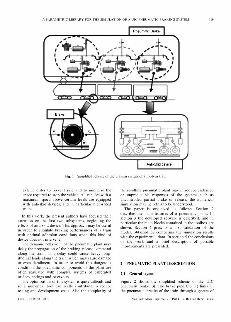
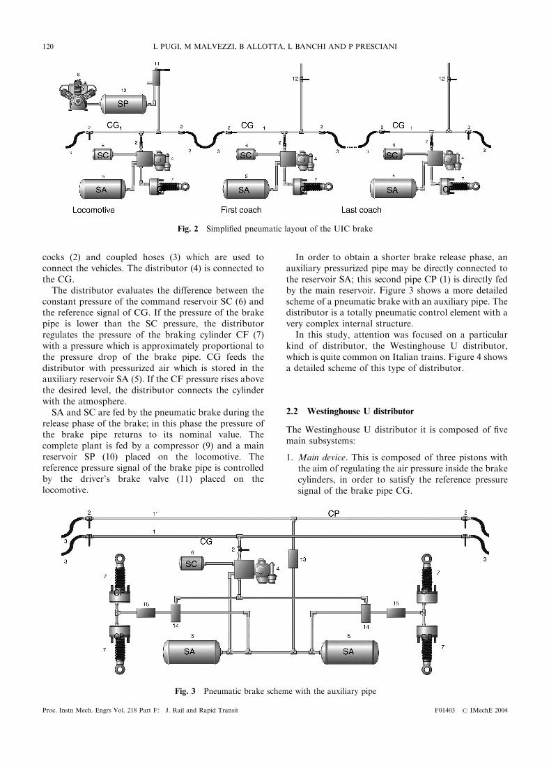
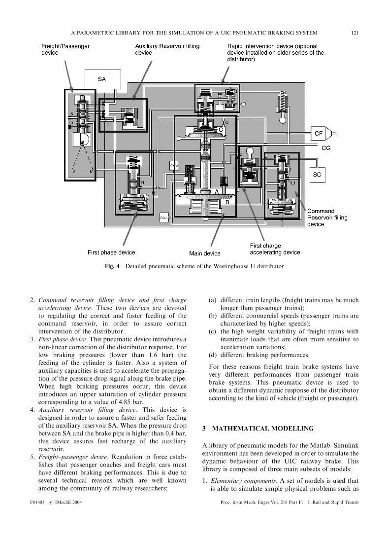
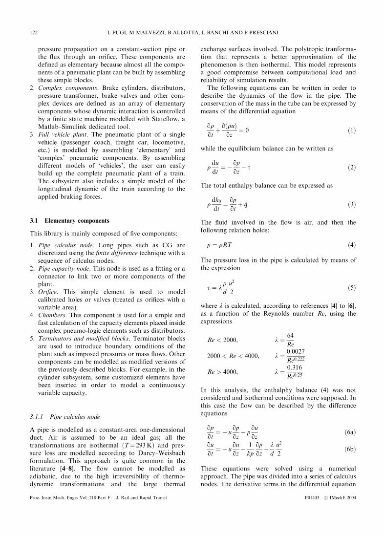
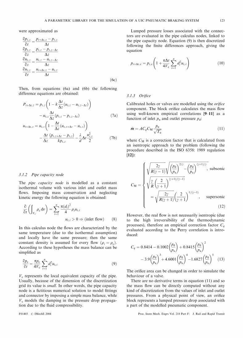
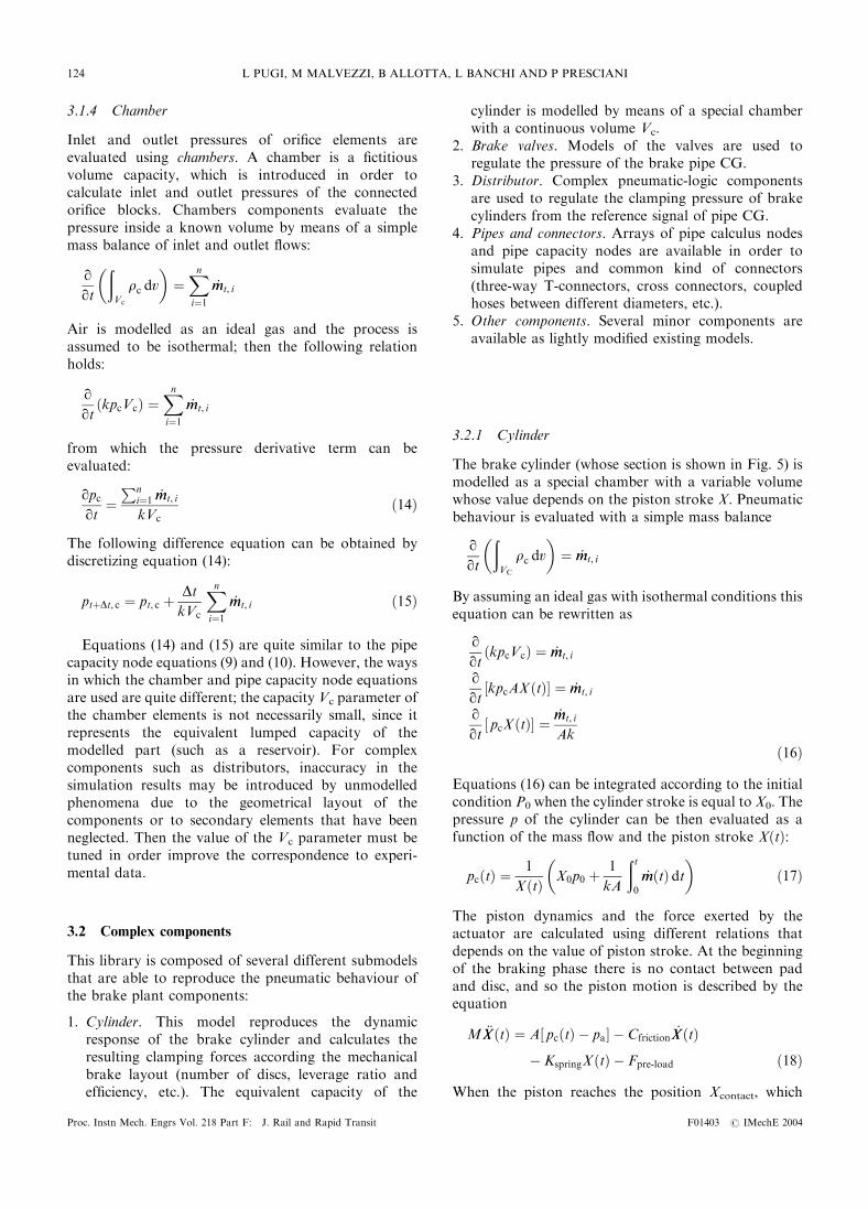
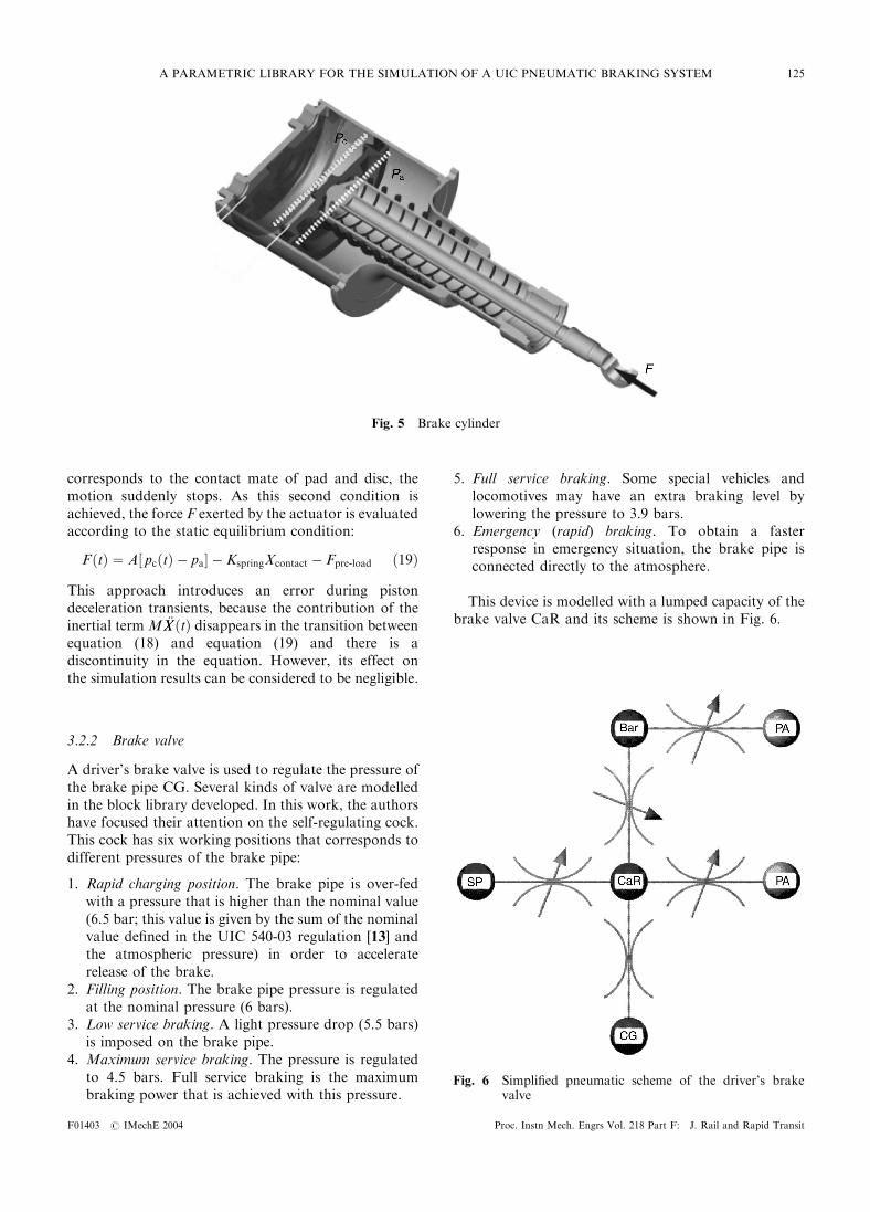
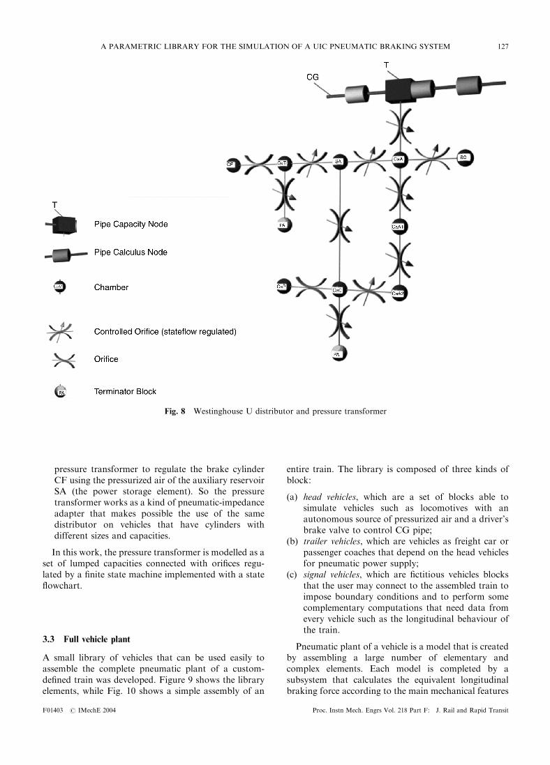
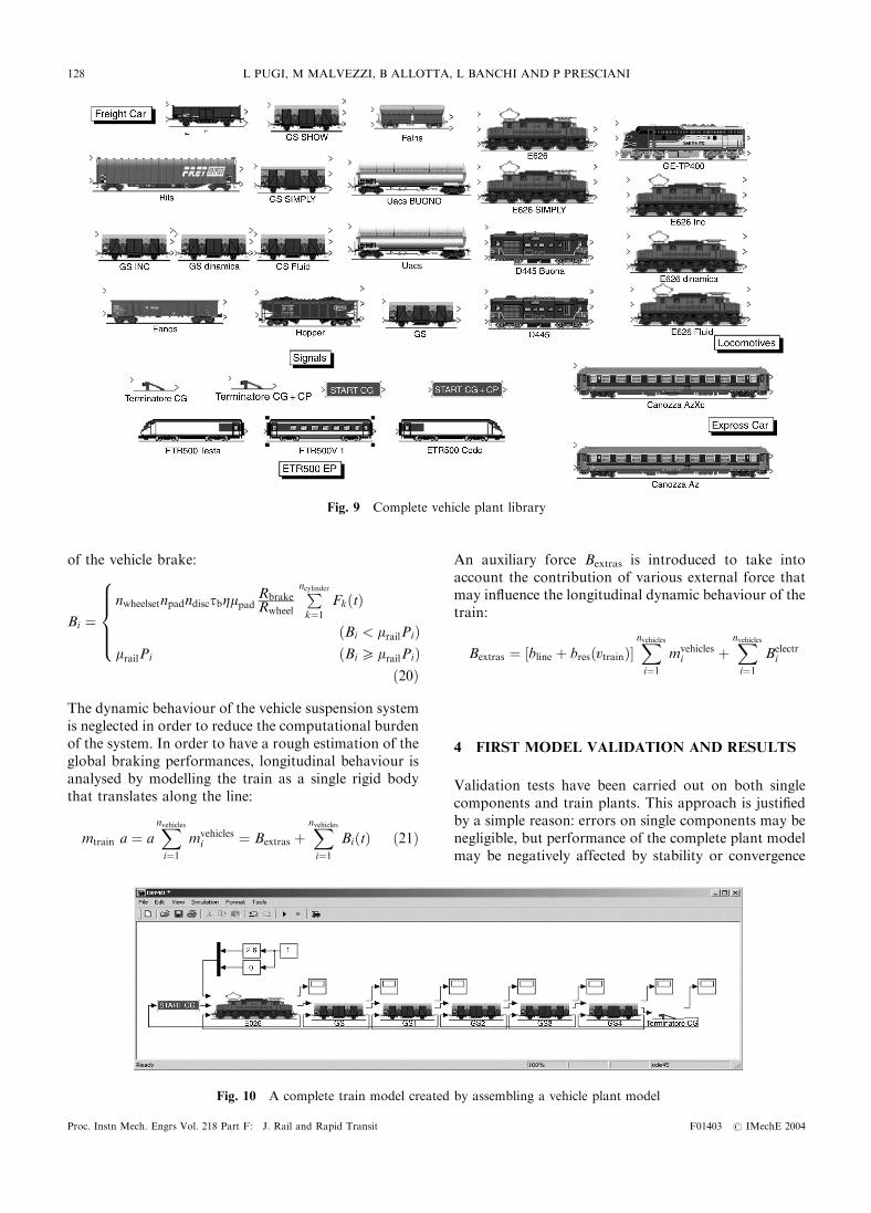
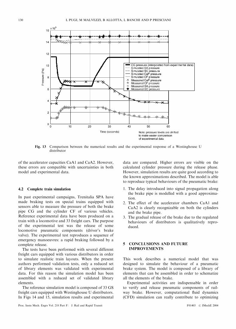
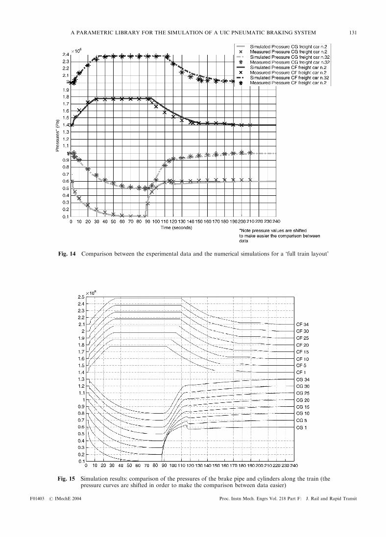
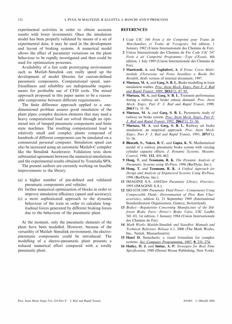