Embed Size (px)
Citation preview
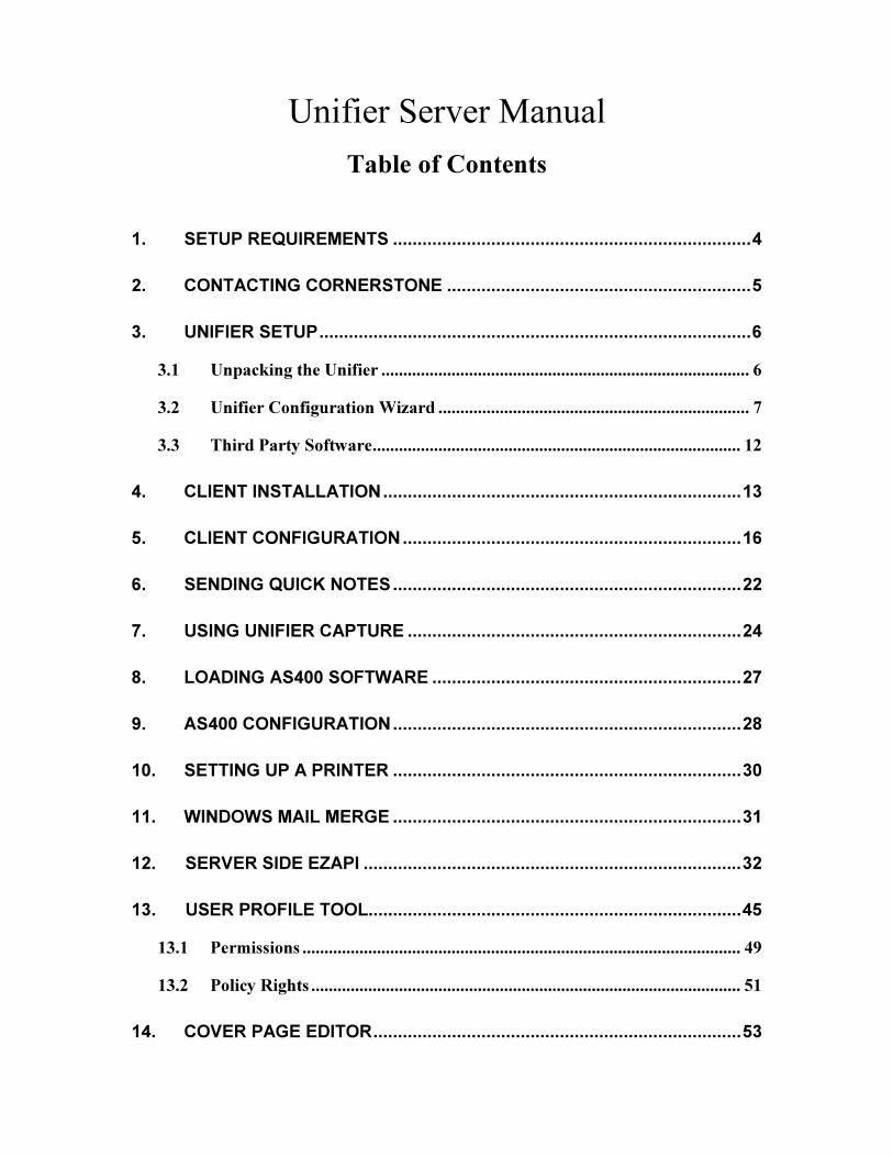
Unifier Server Manual
Table of Contents
1. SETUP REQUIREMENTS ......................................................................... 4
2. CONTACTING CORNERSTONE .............................................................. 5
3. UNIFIER SETUP ........................................................................................ 6
3.1 Unpacking the Unifier .................................................................................... 6
3.2 Unifier Configuration Wizard ....................................................................... 7
3.3 Third Party Software .................................................................................... 12
4. CLIENT INSTALLATION ......................................................................... 13
5. CLIENT CONFIGURATION ..................................................................... 16
6. SENDING QUICK NOTES ....................................................................... 22
7. USING UNIFIER CAPTURE .................................................................... 24
8. LOADING AS400 SOFTWARE ............................................................... 27
9. AS400 CONFIGURATION ....................................................................... 28
10. SETTING UP A PRINTER ....................................................................... 30
11. WINDOWS MAIL MERGE ....................................................................... 31
12. SERVER SIDE EZAPI ............................................................................. 32
13. USER PROFILE TOOL............................................................................ 45
13.1 Permissions .................................................................................................... 49
13.2 Policy Rights .................................................................................................. 51
14. COVER PAGE EDITOR ........................................................................... 53

2
15. ADMINISTRATOR TOOL ........................................................................ 73
15.1 CSID Routing ................................................................................................ 74
15.2 DID Routing .................................................................................................. 75
15.3 Domain Authentication ................................................................................ 76
15.4 DTMF Routing .............................................................................................. 78
15.5 Foreign Address Source Association ........................................................... 79
15.6 Foreign Database .......................................................................................... 84
15.7 Local/Long Distance Table........................................................................... 86
15.8 Port/Port Group Table ................................................................................. 87
15.9 Printer Alias .................................................................................................. 91
15.10 System Backup/Redundancy ....................................................................... 92
15.11 Restore from Backup .................................................................................... 93
15.12 Miscellaneous................................................................................................. 94 15.12.1 LPD Print Queue ....................................................................... 95 15.12.2 Data Dictionary ......................................................................... 97 15.12.3 Export Received or Sent Faxes ................................................ 98 15.12.4 Hot Folder ................................................................................ 100
15.13 Shared Address Books ................................................................................ 102
15.14 System Defaults ........................................................................................... 106
15.15 Sys Info Table .............................................................................................. 112
16. IMAGE UTILITY ..................................................................................... 114
16.1 DCX to PCX ................................................................................................ 115
16.2 PCX to DCX ................................................................................................ 116
16.3 Upload Image .............................................................................................. 117
16.4 Download Image.......................................................................................... 119
16.5 Fax to Image ................................................................................................ 120
16.6 Save PCX ..................................................................................................... 122
3
16.7 OverLay ....................................................................................................... 124
16.8 Image Viewer ............................................................................................... 126
17. UNIFIER MONITOR .................................................................................... 128
17.1 Basic Connectivity Checklist ...................................................................... 131
18. SERVER REPORTS .............................................................................. 133
19. UFORMZ OVERVIEW........................................................................... 137
19.1 Definitions .................................................................................................... 137
19.2 How does it work? ....................................................................................... 137
20. UFORMZ TEMPLATE DESIGNER ........................................................ 139
20.1 Template How Tos ...................................................................................... 140
21. UFORMZ PACKAGE DEFINITIONS (AS400) ....................................... 148
22. UFORMZ PACKAGE DEFINITIONS (WINDOWS) ................................ 153
23. USIGN INSTALL GUIDE ....................................................................... 163
24. UMAIL2FAX ........................................................................................... 169
INDEX ............................................................................................................... 180
4
1. Setup Requirements
1) Static IP Address and Subnet Mask. The Unifier cannot use a dynamically assigned IP address such as DHCP.
2) If you are using DNS, the IP address of your DNS server.
3) Default Gateway IP address. Internet access is required for Windows updates and remote access troubleshooting.
4) If you are utilizing Unifier400 (you have an AS/400 that will be sending work to Unifier), you will need its IP address.
5) Your SMTP server’s IP address or Host Name. Even if you are not using the fax via email feature, you should still supply this. All messages between the Unifier and Administrator (potential problems and other events) and your users (fax notifications, received routed faxes) are sent via email.
6) A UPS conditioned power source.
7) The proper phone lines for the faxboard(s) in your system.
8) A VGA monitor, keyboard and mouse (or KVM setup).

5
2. Contacting Cornerstone
Cornerstone Communications is located in Indianapolis, Indiana.
Technical Support hours are Monday through Friday from 8am to 5pm, Eastern Standard Time.
We can be reached by:
Phone: 317-802-0107, ext. 216
Email: [email protected]
We will return your call/email within 2 business hours.
We also have a Self-Service Portal which enables you to create cases online, enter comments on existing cases, and search Solutions. To access the portal, go to www.cstoneindy.com and click Support Enrollment at the upper right. You will then receive an email with a temporary password.
6
3. Unifier Setup 3.1 Unpacking the Unifier Remove the Unifier from the shipping box. Please save this box and all packing materials as it has been designed to allow safe shipping of the Unifier, and will be needed for returning your Unifier to Cornerstone.
The box should contain:
• The Unifier server with rails.
• A power cord.
• A required “Y-cord” phone cable. The Y-cord has an RJ45 connector at one end that splits into the corresponding number of cables for your faxboard, and RJ11 connectors at the other ends. The RJ45 connector goes into your faxboard; the RJ11 connectors go into active phone jacks.
• A Unifier CD. This CD contains documentation, the Unifier/Windows client software for installation on PCs, uSIGN software, and Unifier400 software for your AS/400. The CD is not to be inserted into the Unifier server. It is strictly for the installation of client (PC) software and AS400 (Unifier400) software.
Plug the power cord into a UPS conditioned power source. Damage caused by lightning, power surges, floods, acts of nature, and other external events are not covered by your Maintenance Agreement.
Connect the Unifier to your network by plugging your network cable into the Network Interface Card. If you have 2 Ethernet ports on your Unifier, use Ethernet port #1.
Plug the RJ45 end of the supplied Y-cable(s) into the faxboard(s).
• If you are using a T1 digital faxboard, you will need ISTP (Individually Shielded Twisted Pair) cabling, which is readily available from any cable supplier. Make sure to use this cable from the demarc (where the Telco terminates their responsibility) to the CSU (recommended), and from the CSU to the faxboard interface.
Plug a mouse into the top port, and a keyboard into the bottom port.
Now power the Unifier on (the master power switch is on the back next to the power cord connector). When the Unifier comes up, the Unifier Configuration Wizard will automatically start.

7
3.2 Unifier Configuration Wizard The Unifier Configuration Wizard performs the initial setup of your Unifier. It is not meant to handle every possible configuration or multiple Unifier environments. Any value you enter in the Configuration Wizard can be changed via the Unifier Administrator Tool. While in the Wizard, you can press the ‘Back’ button to go back and change an entry. Once you click the ‘Finish’ button on the last panel, you will not see the Wizard again.
Figure 1
The ‘Company Name’ field will be used to name several things. Please make sure that it is accurate.
The ‘Fax’ field will be used to start your Local/Long Distance table, which is a list of dialing instructions.
The ‘Administrator Name’ and ‘Administrator Email’ fields will be used to create an ADMIN account (within the Unifier software, not the Operating System software). These values can be changed later.
8
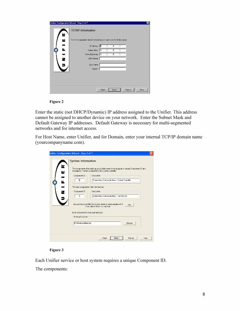
Figure 2
Enter the static (not DHCP/Dynamic) IP address assigned to the Unifier. This address cannot be assigned to another device on your network. Enter the Subnet Mask and Default Gateway IP addresses. Default Gateway is necessary for multi-segmented networks and for internet access.
For Host Name, enter Unifier, and for Domain, enter your internal TCP/IP domain name (yourcompanyname.com).
Figure 3
Each Unifier service or host system requires a unique Component ID.
The components:

9
A) Cluster Controller – The Cluster Controller is where outgoing messages are prepared, cover pages are generated, and all fax routing and email handoff to your company’s SMTP server takes place. It communicates with host systems (AS400’s) and client systems (Windows PC’s). The activity of the Cluster Controller service is logged in the D:\Temp directory.
The service (and its status) is listed in the Services panel on the Unifier desktop. The Cluster Controller service should remain in Manual startup mode. Do not change the startup mode to Automatic.
B) Fax Service – This is what handles the sending, queuing and retrying of outgoing faxes, and reports final disposition of faxes to the appropriate Cluster Controller. Received faxes are also received by the Fax Service and sent to the appropriate Cluster Controller for routing and/or printing.
The activity of the Fax Service is logged in the D:\Temp directory.
The service (and its status) is listed in the Services panel on the Unifier desktop. The Fax service should remain in Manual startup mode. Do not change the startup mode to Automatic.
There are 2 Fax services listed in the Services panel. Only one Fax service will be active, depending on the model of your faxboard.
Accept the default values for the Cluster Controller and the Fax Service Component ID’s.
If you have an AS400 that will be communicating with the Unifier, select ‘Yes’, and the following dialog will be displayed:
Figure 4
Enter the Description and IP Address or Host name of your AS400. (The Component ID should be 3.) If you are licensed for additional AS400 connections, you will add them later.
Next, select a Backup Location by clicking the browse button. This should be a network server that Unifier has full permissions to. The default location is set to the Unifier’s hard drive, which is not recommended. If you allow the Unifier to back up to its own D:\UmsLocalBackup folder, you will need to copy that file off to another server on a regular basis. If you do not copy the local backup folder, you accept the risk of not having a backup in case of hard drive failure.
10
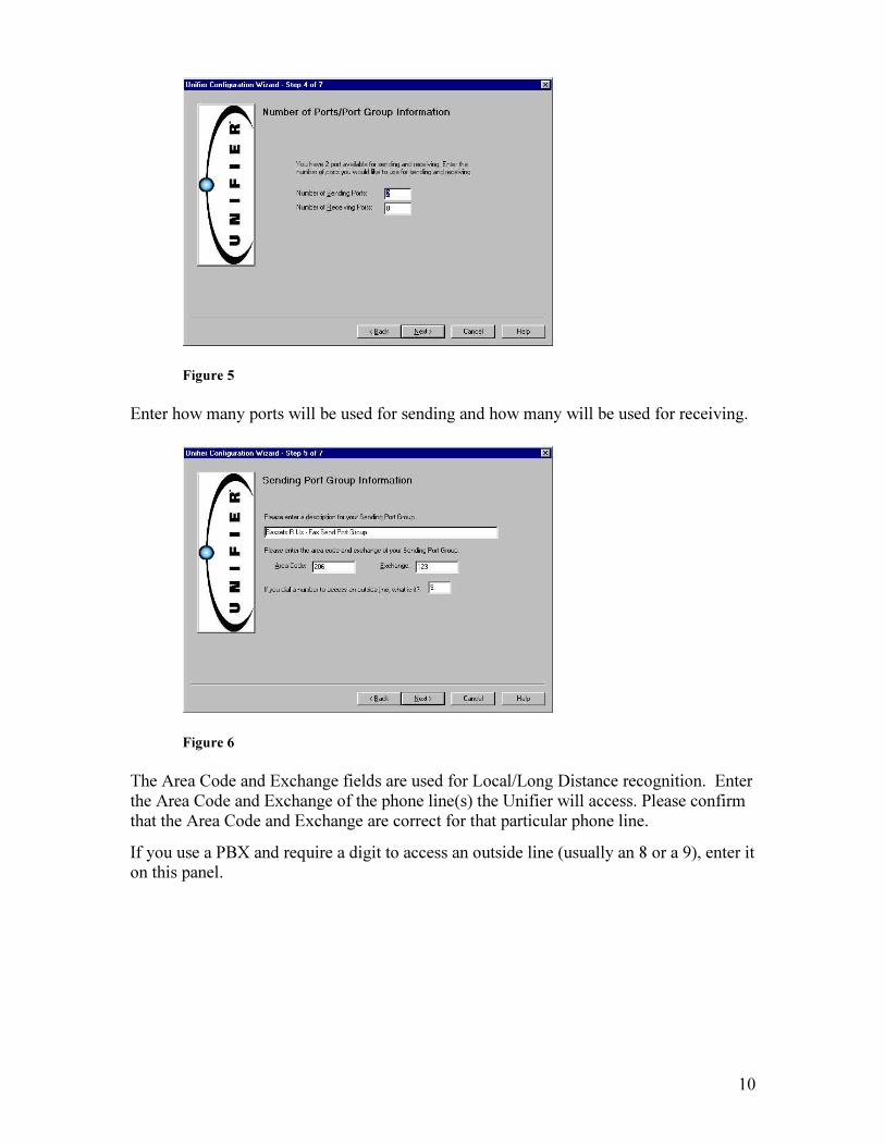
Figure 5
Enter how many ports will be used for sending and how many will be used for receiving.
Figure 6
The Area Code and Exchange fields are used for Local/Long Distance recognition. Enter the Area Code and Exchange of the phone line(s) the Unifier will access. Please confirm that the Area Code and Exchange are correct for that particular phone line.
If you use a PBX and require a digit to access an outside line (usually an 8 or a 9), enter it on this panel.
11
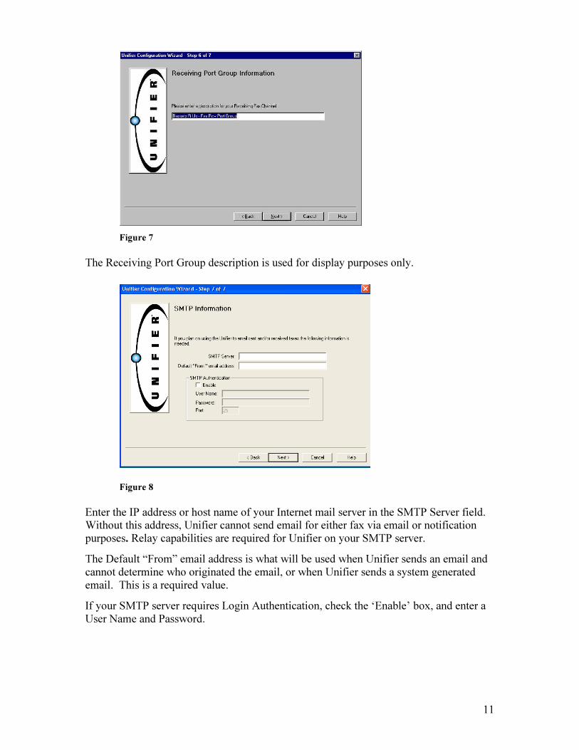
Figure 7
The Receiving Port Group description is used for display purposes only.
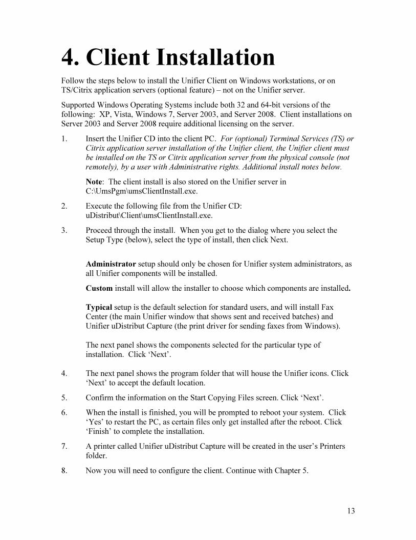
Figure 8
Enter the IP address or host name of your Internet mail server in the SMTP Server field. Without this address, Unifier cannot send email for either fax via email or notification purposes. Relay capabilities are required for Unifier on your SMTP server.
The Default “From” email address is what will be used when Unifier sends an email and cannot determine who originated the email, or when Unifier sends a system generated email. This is a required value.
If your SMTP server requires Login Authentication, check the ‘Enable’ box, and enter a User Name and Password.

12
Figure 9
When the ‘Finish’ button is clicked, your configuration is saved and the Unifier will reboot. When the Unifier powers back up, it will be in production mode.
If you wish to add Unifier to your domain, please contact Cornerstone or the Self-Service portal for a solution.
3.3 Third Party Software When installing antivirus software on the Unifier server, create exclusions to omit the following directories:
C:\UmsPgm
D:\UMS
D:\Temp
Cornerstone recommends that you use Symantec Antivirus software, as it has been tested.
Do not install NOD32 by ESET, TrendMicro, Dexon Agent, or Kaspersky, as these products are known to interfere with Unifier database files.
You may install remote access software, UPS software, and/or backup software on the Unifier server. However, if we determine that you are having performance issues that are hindering Unifier’s functionality, we may recommend that you remove it.
Windows updates, patches and Service Packs should be installed regularly on the Unifier server. It is best to allow Unifier to download Windows updates, but let you install them, so that you can control the reboot.
Please do not install screen savers, as they are unnecessary and have been known to cause problems.
13
4. Client Installation Follow the steps below to install the Unifier Client on Windows workstations, or on TS/Citrix application servers (optional feature) – not on the Unifier server.
Supported Windows Operating Systems include both 32 and 64-bit versions of the following: XP, Vista, Windows 7, Server 2003, and Server 2008. Client installations on Server 2003 and Server 2008 require additional licensing on the server.
1. Insert the Unifier CD into the client PC. For (optional) Terminal Services (TS) or Citrix application server installation of the Unifier client, the Unifier client must
be installed on the TS or Citrix application server from the physical console (not
remotely), by a user with Administrative rights. Additional install notes below.
Note: The client install is also stored on the Unifier server in C:\UmsPgm\umsClientInstall.exe.
2. Execute the following file from the Unifier CD: uDistribut\Client\umsClientInstall.exe.
3. Proceed through the install. When you get to the dialog where you select the Setup Type (below), select the type of install, then click Next.
Administrator setup should only be chosen for Unifier system administrators, as all Unifier components will be installed.
Custom install will allow the installer to choose which components are installed.
Typical setup is the default selection for standard users, and will install Fax Center (the main Unifier window that shows sent and received batches) and Unifier uDistribut Capture (the print driver for sending faxes from Windows).
The next panel shows the components selected for the particular type of installation. Click ‘Next’.
4. The next panel shows the program folder that will house the Unifier icons. Click ‘Next’ to accept the default location.
5. Confirm the information on the Start Copying Files screen. Click ‘Next’.
6. When the install is finished, you will be prompted to reboot your system. Click ‘Yes’ to restart the PC, as certain files only get installed after the reboot. Click ‘Finish’ to complete the installation.
7. A printer called Unifier uDistribut Capture will be created in the user’s Printers folder.
8. Now you will need to configure the client. Continue with Chapter 5.
14
For Unifier versions that are divisible by 10 (that end in 0): When server version updates are applied to your Unifier, all Windows clients will be automatically prompted to update the first time they log on to the Unifier or try to send a fax.
For all other Unifier versions: When server version updates are applied to your Unifier, and the client was not prompted to update (but you wish to distribute the latest version feature to the client), open Fax Center on the client PC, then click Tools-Update Client.
Additional install notes for (optional) Terminal Services (TS) or Citrix application
servers:
Cornerstone supports the TS/Citrix environment running under a Windows Server 2003 or 2008 platform. This requires additional licensing on the Unifier server.
1. The printer that is created in the Terminal Services/Citrix installation is called Unifier uDistribut TS/Citrix, instead of Unifier uDistribut Capture (Windows). For environments that are using both TS/Citrix and Windows Unifier client setups, the correct printer must be used, depending on the environment the user is
printing from. Two Capture icons ( ) will appear in the user’s system tray if both environments are being used.
The Capture Monitor is what causes the Assign Destination to Fax window to appear after a user has selected File-Print, and has chosen the Unifier uDistribut TS/Citrix printer. The Capture Monitor must be started for a Capture to work, and is started when the Capture icon appears in the user’s system tray.
2. The Unifier Capture Monitor will start when you open your TS/Citrix desktop. However, if you are using individually published Citrix applications (see #3 below), you will have to start the Unifier Capture Monitor before printing from any Citrix application.
One method of starting the Capture Monitor automatically is to create a batch file that starts it, then starts the individual application. You would then need to publish the batch file. Batch files can be created in any text editor and saved with a .cmd extension.
Batch File Example
START uCapNtM.exe
START umsWrkFax.exe
EXIT
The Capture Monitor may be started several times with no harmful effects, as only one instance will run at a time. If you are using the batch file approach, you may include a “START Capture Monitor” command in several batch files that start different Unifier applications.
3. After the Unifier client is installed on the TS/Citrix application server, users can connect to the application server in order to use any Unifier applications:
15
In a TS environment, users will log on to the application server desktop, and will be able to utilize all applications they have permissions to.
In a Citrix environment, the Citrix administrator decides how to make applications available to users:
• The Citrix administrator may give rights to the entire Citrix desktop.
• The Citrix administrator may choose to publish specific Unifier applications. The administrator will need to know what folder the Unifier applications reside in (by default, the location is C:\ProgramFiles\CornerstoneCommunications\Unifier). Users will then see desktop shortcuts to published programs on the Citrix server.
4. Domain authentication must be enabled in order for the Unifier TS/Citrix client to work, in the following areas:
• Unifier Administrator Tool. Open the Administrator Tool, then click on Edit-Domain Authentication, and create an entry.
• Client configuration for each user. Open the Fax Center screen on the user’s desktop. Click on View-Options-Advanced, and check the ‘Enable Domain Authentication’ box.
• User Profile Tool. In each user profile, a valid domain and user name must be listed, and the function box ‘Allow Domain Logon’ must be checked.
16
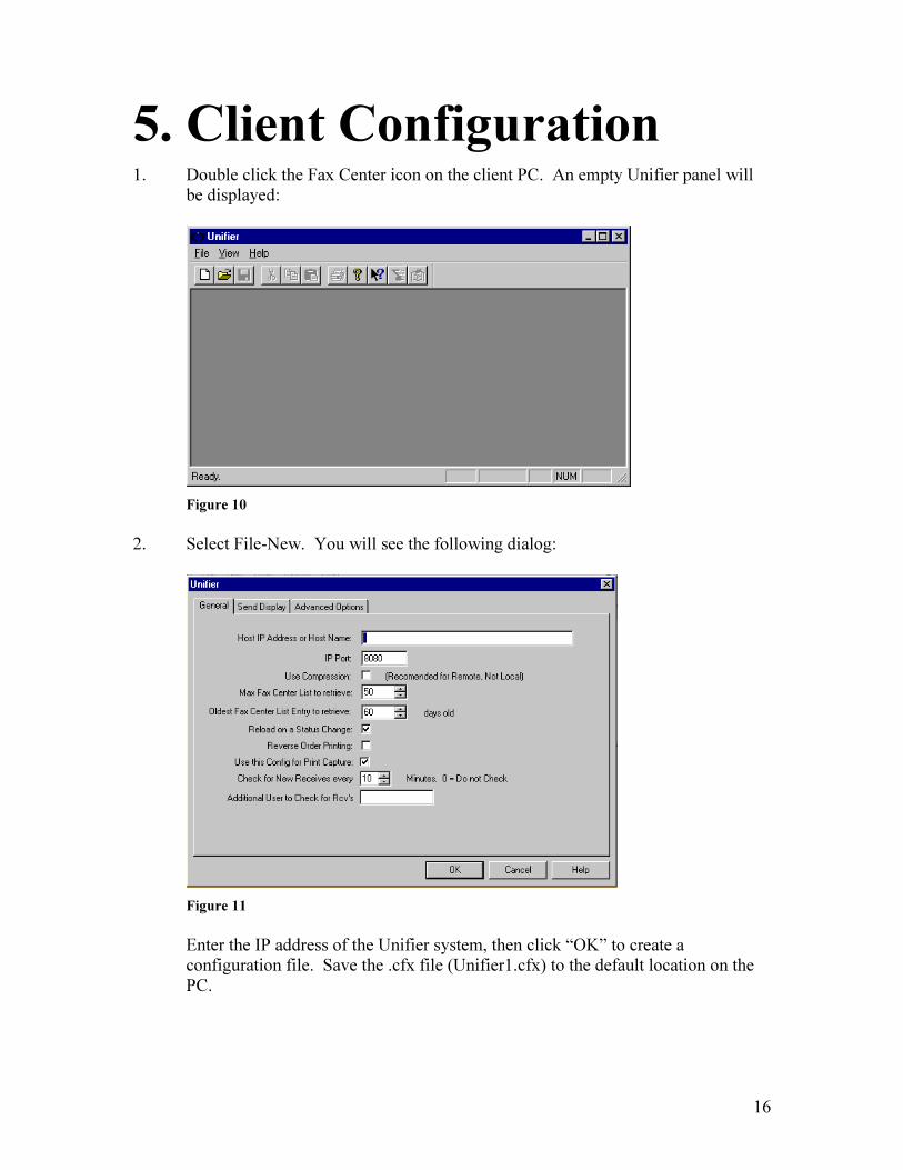
5. Client Configuration 1. Double click the Fax Center icon on the client PC. An empty Unifier panel will
be displayed:
Figure 10
2. Select File-New. You will see the following dialog:
Figure 11
Enter the IP address of the Unifier system, then click “OK” to create a configuration file. Save the .cfx file (Unifier1.cfx) to the default location on the PC.

17
Field Definitions
Host IP Address or Host Name: The IP Address or Host Name (if you are using DNS) of your Unifier.
IP Port: The TCP/IP port the client will use to communicate. Leave this at 8080.
Use Compression: This option is not recommended for a local connection or a remote connection that already uses compression.
Max Fax Center List to Retrieve: Maximum number of fax entries to retrieve. The higher this number is, the longer it will take for the requested number of entries to be retrieved.
Reload on a status change: Check this box to reload the list if the status of one of the faxes listed changes (after deleting, forwarding, rerouting).
Reverse Order Printing: Print in reverse order, beginning with the last page. This is used for some inkjet printers.
Use this config for Print Capture: Check this box to use the same configuration for Unifier Capture. (Capture will automatically use the last Unifier client configuration with this box checked.)

18
Send Display
Figure 12
Field Definitions
Description for Send Items: Check the fields you wish to appear in the description for sent faxes. This option may be reset at any time via a context menu (right-click button).
Display Successful Send Batches: Check if you wish to see batches that were sent successfully. This option may be reset at any time via a context menu (right-click button).
Don’t Show if Priority greater than: Use this field to keep low-priority faxes (broadcast or test faxes) off the list.
Selection Enabled: Check to enable selection of faxes for a specific department and/or user. This option may be reset at any time via a context menu (right-click button).
Department: If selection enabled, enter department to be selected.
User: If selection enabled, enter user to be selected.
Max Log Entries to Download: Maximum number of log file entries (batches) that will be downloaded.
Oldest Log Entry (in days): Maximum age (in days) of log file entries that will be downloaded.

19
Advanced Options
Figure 13
Field Definitions
Trace Level: Use only if advised to do so by Cornerstone Communications.
Truncate Log on Startup: Use only if advised to do so by Cornerstone Communications.
Trace File: Use only if advised to do so by Cornerstone Communications.
Background Caching of Images: Recommended unless running Unifier client on a low-speed machine.
Cache Directory: If background caching enabled, directory to use for cache.
Enable MAPI Address Books: Use MAPI compatible address books (Outlook).
Enable Windows Address Books: Use Windows address books (Outlook Express).
Enable Domain Authentication: Enable the Domain Authentication feature to enroll new users from your network. If this box is checked, when a user logs on to Unifier and is not registered as a Unifier user, a Unifier user profile will be created and no further password is required for logon.
20
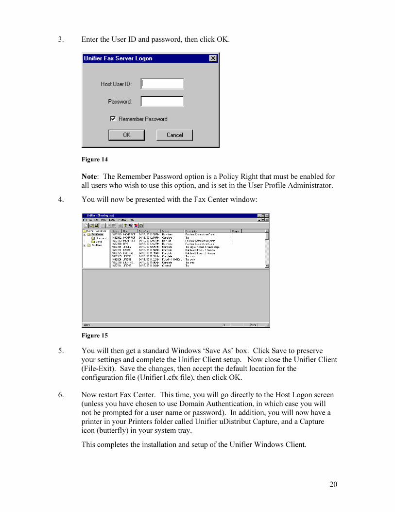
3. Enter the User ID and password, then click OK.
Figure 14
Note: The Remember Password option is a Policy Right that must be enabled for all users who wish to use this option, and is set in the User Profile Administrator.
4. You will now be presented with the Fax Center window:
Figure 15
5. You will then get a standard Windows ‘Save As’ box. Click Save to preserve your settings and complete the Unifier Client setup. Now close the Unifier Client (File-Exit). Save the changes, then accept the default location for the configuration file (Unifier1.cfx file), then click OK.
6. Now restart Fax Center. This time, you will go directly to the Host Logon screen (unless you have chosen to use Domain Authentication, in which case you will not be prompted for a user name or password). In addition, you will now have a printer in your Printers folder called Unifier uDistribut Capture, and a Capture icon (butterfly) in your system tray.
This completes the installation and setup of the Unifier Windows Client.

21
Note: If installing the Unifier client on multiple workstations, you may copy the Unifier1.cfx configuration file to each user’s PC rather than doing a manual installation on all PC’s. Or, you may put the Unifier1.cfx file in a public location on your network for users to access. All users, however, must have a copy of the Unifier1.cfx file stored on the local PC.
22
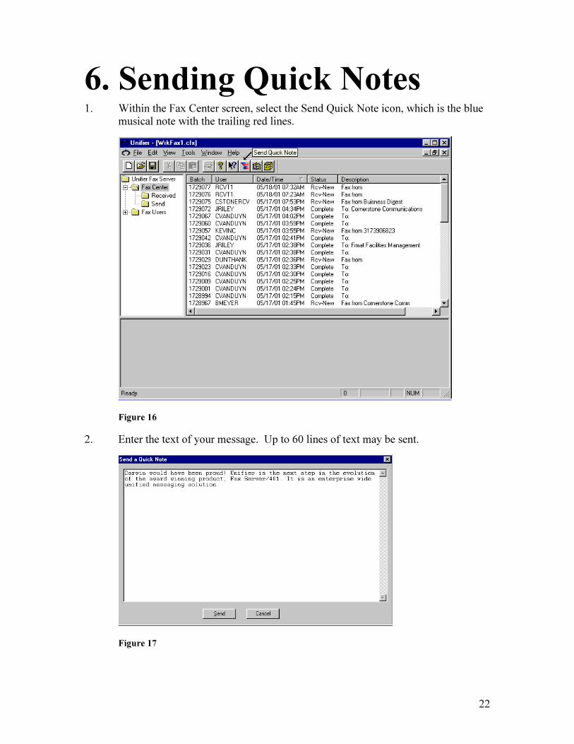
6. Sending Quick Notes 1. Within the Fax Center screen, select the Send Quick Note icon, which is the blue
musical note with the trailing red lines.
Figure 16
2. Enter the text of your message. Up to 60 lines of text may be sent.
Figure 17
23
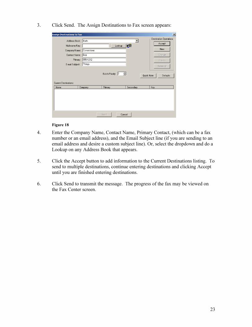
3. Click Send. The Assign Destinations to Fax screen appears:
Figure 18
4. Enter the Company Name, Contact Name, Primary Contact, (which can be a fax number or an email address), and the Email Subject line (if you are sending to an email address and desire a custom subject line). Or, select the dropdown and do a Lookup on any Address Book that appears.
5. Click the Accept button to add information to the Current Destinations listing. To
send to multiple destinations, continue entering destinations and clicking Accept until you are finished entering destinations.
6. Click Send to transmit the message. The progress of the fax may be viewed on
the Fax Center screen.

24
7. Using Unifier Capture Faxing output from a Windows application is as easy as sending the output to a printer. Included are capture drivers for the following Windows operating systems (both 32 and 64-bit): XP, Vista, Windows 7, Server 2003, and Server 2008.
Open the Windows document to be faxed.
1. Click File-Print.
2. Select the Unifier uDistribut Capture printer, then click ‘OK’. The Assign Destinations to Fax window will appear.
3. Enter desired contact information. Enter the fax number or email address in the Primary field. Or, select an address book from the Address Book dropdown.
Note: Access to Address Books is a Policy Right that will need to be granted to users who wish to utilize Address Books of various types. Policy rights are granted in the User Profile Tool.
4. Click Accept. You will now see the destination listed in the bottom part of the Fax Center screen.
5. Multiple destinations can be entered by repeating steps 4 and 5.
6. Your document can be previewed at any time by clicking on the Preview button.
7. Click Send to send your fax. You can view the status of the batch in the Fax Center screen.
8. To resend a batch, right click on it, then select either ‘Resend All’ to resend both Complete and Failed destinations, or ‘Resend this Batch’ to resend only Failed destinations.
PACKAGE EDITOR
Selected pages from received and sent faxes and Windows Capture documents can be saved and recombined into a faxable package. The ‘Save for Later’ option in the Assign Destinations to Fax window allows a document to be saved, then individual pages from that document can be assembled into a package with pages from other documents for faxing or emailing.
1. Open the document you wish to Save for Later. (If you wish to store a sent or received fax from the Fax Center screen, right click on the batch, then select ‘Preview Body Document’. Right click on the body in the lower part of the window and select ‘Store for Package’. Then skip to Step 4 below.)
2. Click File-Print, and choose the Unifier uDistribut Capture printer.
25
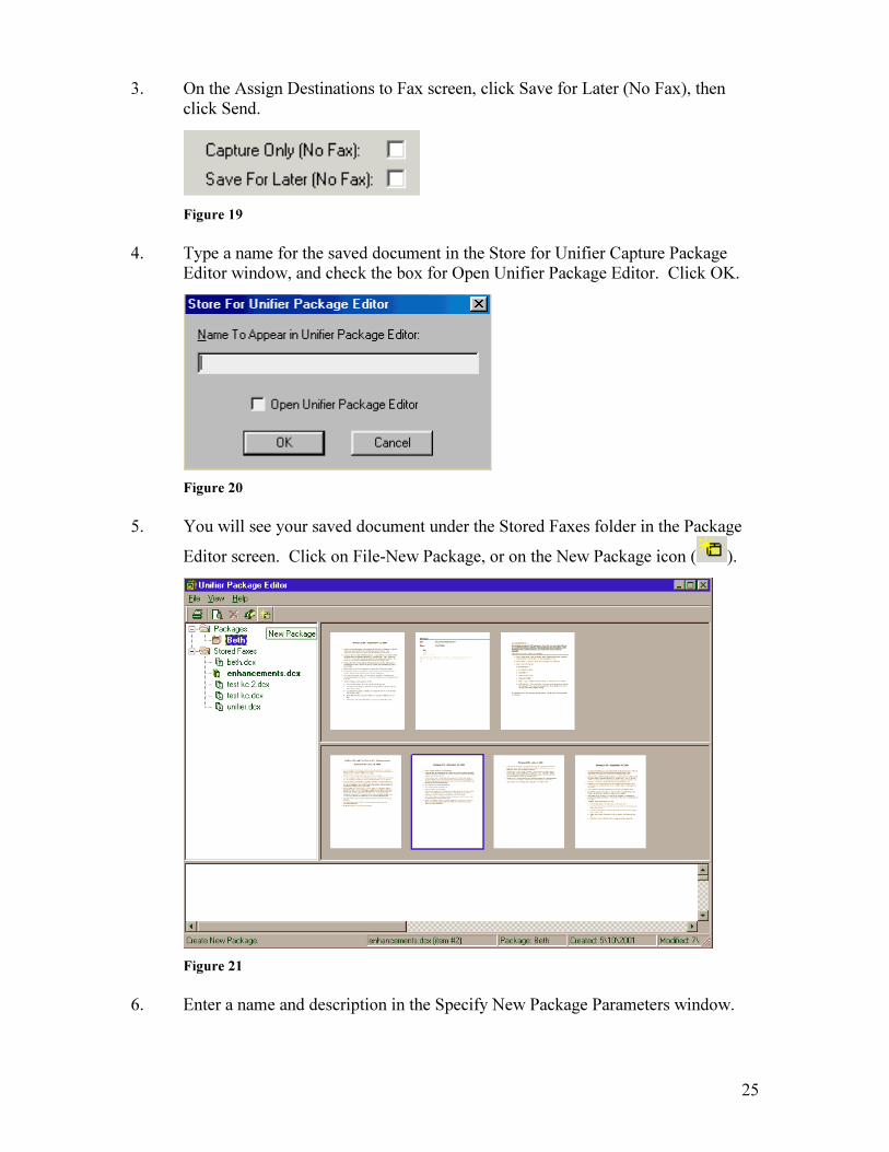
3. On the Assign Destinations to Fax screen, click Save for Later (No Fax), then click Send.
Figure 19
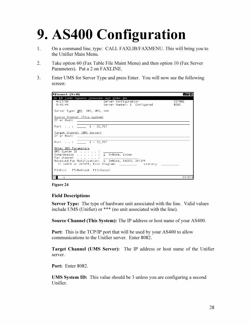
4. Type a name for the saved document in the Store for Unifier Capture Package Editor window, and check the box for Open Unifier Package Editor. Click OK.
Figure 20
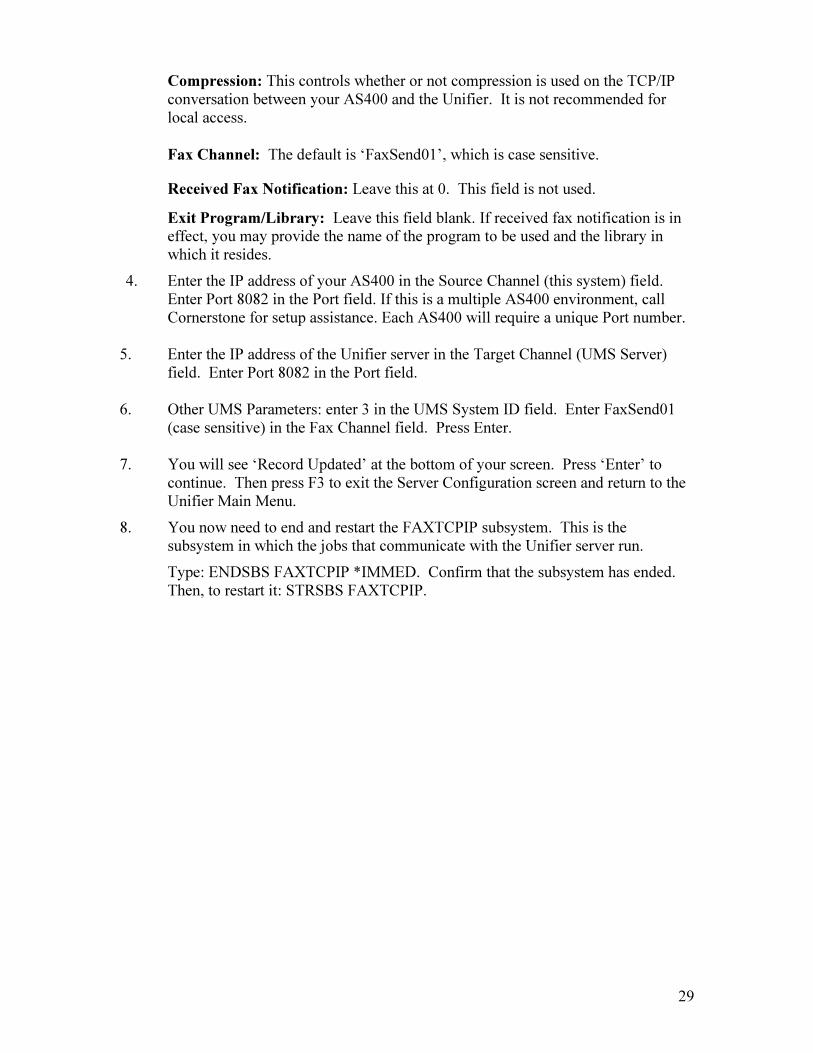
5. You will see your saved document under the Stored Faxes folder in the Package
Editor screen. Click on File-New Package, or on the New Package icon ( ).
Figure 21
6. Enter a name and description in the Specify New Package Parameters window.

26
Figure 22
7. To add a page to your Package, simply drag and drop the thumbnail from the lower portion of the window (Stored Faxes window) to the upper portion of the window (Package window). Red arrows will appear to designate placement of the dragged page.
8. To reorder pages within your Package, just drag one page on top of another. Red arrows will appear to designate placement of the dragged page.
9. To fax your Package, click on the Send Package icon ( ). You will then be presented with the Assign Destinations to Fax window. Enter the fields as desired and click Send.

27
8. Loading AS400 Software 1. Insert the Unifier CD into your AS400 (instructions to download the software
from a link are also available).
2. Sign on as QSECOFR and go to a command line.
3. Type LODRUN *OPT and press Enter.
4. You will see a prompt asking if you want to install Faxserver401. Reply Y. (Faxserver401 is our legacy product.)
5. You will now see a screen asking if you want to run the install interactively or in batch. We recommend you run the install interactively (option 1). The installation will take approximately 2 minutes or less, and is about 100 MB in size.
Figure 23
AS/400 Upgrades and Licensing
If you plan to implement a new production AS400 with a different serial number, or a new physical box, contact Cornerstone for migration instructions and a license agreement. Processor upgrades do not require a new license agreement. There is no fee associated with migration to a new system, as long as you are current on maintenance.
As of the current AS400 Faxlibrary version (FAXLIB v6.74), all licensing is handled by the Unifier server, and license keys are not necessary for the AS400. In the Update License Codes application on the Unifier desktop, the field ‘U400 Connections’ specifies how many AS400 connections (IP addresses) you are licensed for. A connection can mean either a separate system or a partition of your production system.
If you require a (temporary) DR testing ‘U400 Connections’ license, contact Cornerstone.
28
9. AS400 Configuration 1. On a command line, type: CALL FAXLIB/FAXMENU. This will bring you to
the Unifier Main Menu.
2. Take option 60 (Fax Table File Maint Menu) and then option 10 (Fax Server Parameters). Put a 2 on FAXLINE.
3. Enter UMS for Server Type and press Enter. You will now see the following screen:
Figure 24
Field Descriptions
Server Type: The type of hardware unit associated with the line. Valid values include UMS (Unifier) or *** (no unit associated with the line). Source Channel (This System): The IP address or host name of your AS400. Port: This is the TCP/IP port that will be used by your AS400 to allow communications to the Unifier server. Enter 8082. Target Channel (UMS Server): The IP address or host name of the Unifier server. Port: Enter 8082. UMS System ID: This value should be 3 unless you are configuring a second Unifier.
29
Compression: This controls whether or not compression is used on the TCP/IP conversation between your AS400 and the Unifier. It is not recommended for local access.
Fax Channel: The default is ‘FaxSend01’, which is case sensitive.
Received Fax Notification: Leave this at 0. This field is not used.
Exit Program/Library: Leave this field blank. If received fax notification is in effect, you may provide the name of the program to be used and the library in which it resides.
4. Enter the IP address of your AS400 in the Source Channel (this system) field. Enter Port 8082 in the Port field. If this is a multiple AS400 environment, call Cornerstone for setup assistance. Each AS400 will require a unique Port number.
5. Enter the IP address of the Unifier server in the Target Channel (UMS Server) field. Enter Port 8082 in the Port field.
6. Other UMS Parameters: enter 3 in the UMS System ID field. Enter FaxSend01
(case sensitive) in the Fax Channel field. Press Enter. 7. You will see ‘Record Updated’ at the bottom of your screen. Press ‘Enter’ to
continue. Then press F3 to exit the Server Configuration screen and return to the Unifier Main Menu.
8. You now need to end and restart the FAXTCPIP subsystem. This is the subsystem in which the jobs that communicate with the Unifier server run.
Type: ENDSBS FAXTCPIP *IMMED. Confirm that the subsystem has ended. Then, to restart it: STRSBS FAXTCPIP.

30
10. Setting Up A Printer
Install the printer driver software onto the Unifier server as if installing a printer on a workstation.
1. If this is a network printer, you must:
o Create a profile called Unifier with password 4231w96 on the Primary Domain Controller on your network.
o Create a profile called Unifier with password 4231w96 on a workstation, if that is what the printer is attached to. Make sure it is a workstation that can be accessed by all users.
o Create a profile called Unifier with password 4231w96 on your Print Server, if that is what the printer is attached to.
o Log on to the Unifier (log on to the local machine; do not install the printer logged on to a domain) and install the printer as a network printer.
2. Reboot the Unifier after the printer driver installation and print a test page. If the printer is listed in the Printers folder on the Unifier server, and you see the printer in any Unifier window that has a Printers dropdown (such as a Unifier user profile), then it is available to the Unifier system.
3. If you are having trouble printing a test page, make sure you have installed the latest driver from the printer manufacturer’s website.
4. If the printer is to be accessed from the AS400, assign the printer an alias (no longer than eight characters). To create an alias, open the Administrator Tool, click Edit, then Printer Alias. You will see the printer you just installed in the Printers dropdown. The alias is to be used on the AS400 only.

31
11. Windows Mail Merge Windows Mail Merge allows one PC document or report to generate multiple faxes with no human intervention, using the existing Mail Merge feature in Windows.
1. Keywords need to be added to your document to specify fax or email destinations. On the first page of each section, insert the following:
##~~Keyword=Value~~
The Keyword can be “fax”, “company” or “person”, and “value” is the actual value of the Keyword. Any font can be used. The Capture driver will strip out everything between the ##~~ and the trailing ~~ and use the value when faxing.
These keywords can be placed either on the first page of a multiple page section, or on each page. Only one destination may be listed per page. A new fax will be generated when the values change.
Example:
##~~Fax=555-5555~~
##~~Company=Cornerstone Communications~~
##~~Person=Kevin Calhoun~~
----page break---
##~~Company=ABC Company~~
##~~Person=Xavier~~
The above will send one fax to Kevin Calhoun at Cornerstone Communications via fax to 555-5555, and another to Xavier at ABC Company via email to [email protected].
2. Right click on the Unifier Capture printer in the Printers (or Devices and Printers) folder on your PC.
3. Select Printing Preferences, then select the File Formats tab. Make sure the File Format option is set to ‘PCX’.
4. Check the Extract Text to File option and the Mail Merge option on the right.
5. Click OK, then close the Printers folder.
6. Now open the document, select File - Print, and select the Unifier Capture printer.
7. Be sure to change the printer settings back after the Mail Merge is complete.
32
12. Server Side EzAPI
Cornerstone’s legacy EzAPI application, previously configured only on the AS400, enables you to automatically configure specific output requirements for AS400 spooled files or ASCII text documents (via the optional uHOST module) with no human intervention, as long as the host data contains destination information.
You may specify selection criteria within an EzAPI definition that will determine how your host data is processed and output, including print options, (optional) uFORMz integration, customized email subject lines, and other options. If you are faxing an AS400 spooled file, and you specify destination *EZAPI, each EzAPI definition will be checked (in sequence number) to find one that fits the selection criteria. There is an automatic type outqueue on the AS400 that will send any spoolfile to the Unifier to be processed by Server Side EzAPI definition. Instructions for setting up that outqueue are included in this chapter.
When text data is sent from your host system to the Unifier via an LPR command (via the optional uHOST module), the EzAPI definitions are searched until a match is found. The format of the LPR command is:
LPR -S ‘IP address of Unifier” -P ‘Name of LPD Print Q’ ‘Path of text file on the application server’
Example: LPR –S 10.1.2.140 –P AR-Invoices C:\Temp\Invoice.txt
Server Side EzAPI can also be used to extract index values (searchable fields) for use with Cornerstone’s optional uSTOR/Document Mountain storage application.
EzAPI Definition Screens
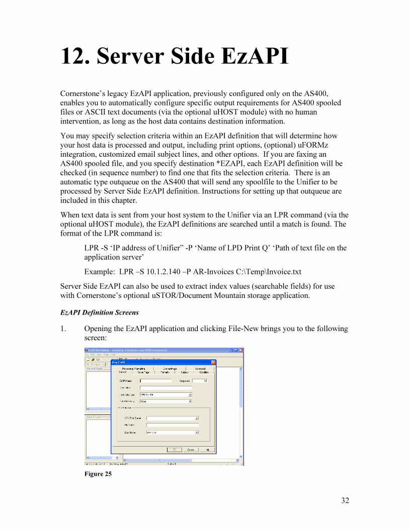
1. Opening the EzAPI application and clicking File-New brings you to the following screen:
Figure 25

33
Field Descriptions
EzAPI Name: The name of your EzAPI definition, a maximum value of 10 characters.
Sequence: The sequence number determines what order the definitions will be checked when host data is sent to the Unifier. When you create a new definition, note that the sequence number is incremented by 10.
Description: A description of the definition for your use only.
Host Data Type: The type of host data that will be used for this definition. Options are AS400 Spooled File, ASCII Text*, CSV File*, and Excel File*.
*For use only with optional uHOST module
Data Dictionary: Data dictionaries contain additional fields for use in selecting the host data you want to include as destination information (used for exporting Sent or Received Faxes). Data dictionaries must be created first in the Administrator Tool - Miscellanous.
LPD Print Queue: The name of the LPD Print Queue that you have set up for this definition. Only available for definitions that use text files, using optional uHOST module.
File Name: Any file with this name will be processed with this definition. Only available for definitions that use text files, using optional uHOST module.
User Name: Any file sent by this user will be processed with this definition.
Spooled File Name: Any spooled file by this name will be processed with this definition. Only available for definitions that use AS400 spooled files.
Form Type: Any spooled file with this form type will be processed with this definition. Only available for definitions that use AS400 spooled files.
User Data: Any spooled file with this user data will be processed with this definition. Only available for definitions that use AS400 spooled files.
2. Clicking on the Cover Page Tab brings you to the following screen:
34
Figure 26
Field Descriptions:
Include Cover Page: Options are Sender Default (Cover Page options in the Sender’s Unifier User Profile will be used); Always (always include a Cover Page); and Never (never include a Cover Page).
Cover Page Template: Options are Sender Default (Cover Page options in the Sender’s Unifier User Profile will be used); None, or a dropdown that lists all available Cover Pages created in the Unifier Cover Page Editor.
Customize Sender Information: If checked, enter a Company Name, Person Name, Voice Phone, or Fax Phone to override those options on any chosen Cover Page.
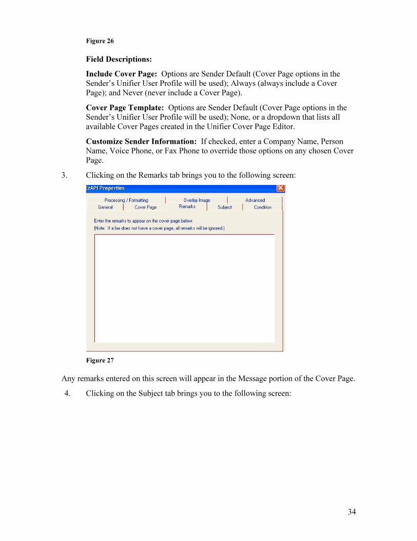
3. Clicking on the Remarks tab brings you to the following screen:
Figure 27
Any remarks entered on this screen will appear in the Message portion of the Cover Page.
4. Clicking on the Subject tab brings you to the following screen:
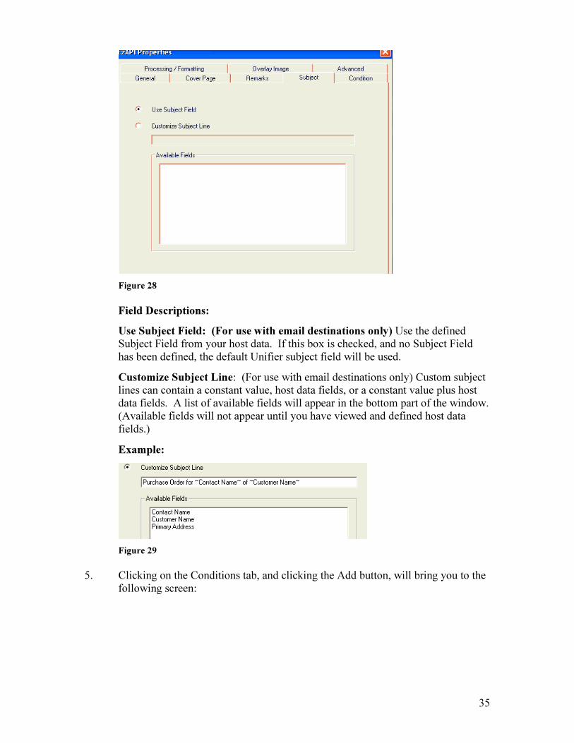
35
Figure 28
Field Descriptions:
Use Subject Field: (For use with email destinations only) Use the defined Subject Field from your host data. If this box is checked, and no Subject Field has been defined, the default Unifier subject field will be used.
Customize Subject Line: (For use with email destinations only) Custom subject lines can contain a constant value, host data fields, or a constant value plus host data fields. A list of available fields will appear in the bottom part of the window. (Available fields will not appear until you have viewed and defined host data fields.)
Example:
Figure 29
5. Clicking on the Conditions tab, and clicking the Add button, will bring you to the following screen:
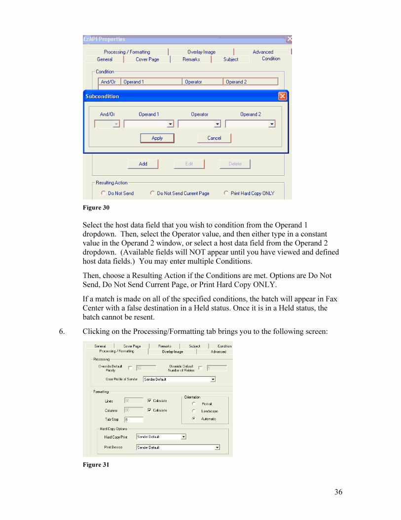
36
Figure 30
Select the host data field that you wish to condition from the Operand 1 dropdown. Then, select the Operator value, and then either type in a constant value in the Operand 2 window, or select a host data field from the Operand 2 dropdown. (Available fields will NOT appear until you have viewed and defined host data fields.) You may enter multiple Conditions.
Then, choose a Resulting Action if the Conditions are met. Options are Do Not Send, Do Not Send Current Page, or Print Hard Copy ONLY.
If a match is made on all of the specified conditions, the batch will appear in Fax Center with a false destination in a Held status. Once it is in a Held status, the batch cannot be resent.
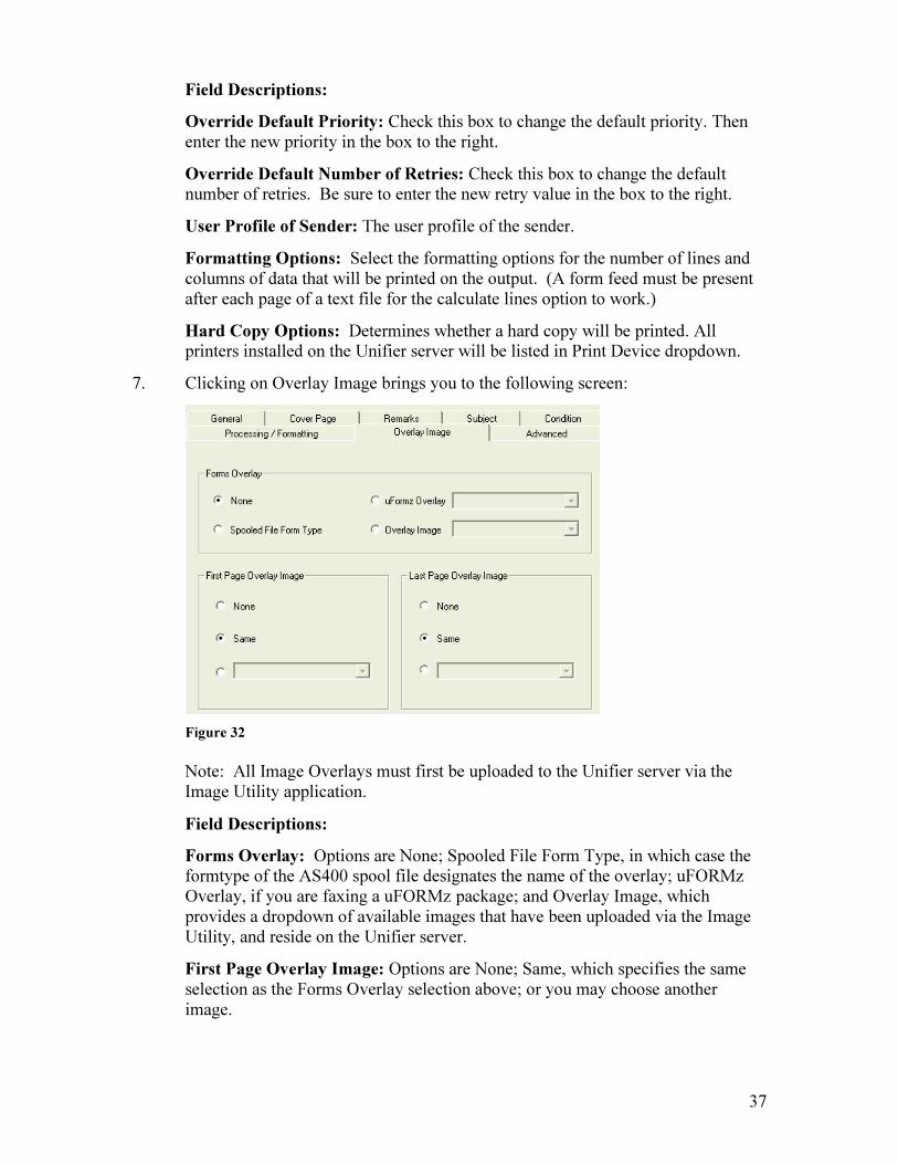
6. Clicking on the Processing/Formatting tab brings you to the following screen:
Figure 31
37
Field Descriptions:
Override Default Priority: Check this box to change the default priority. Then enter the new priority in the box to the right.
Override Default Number of Retries: Check this box to change the default number of retries. Be sure to enter the new retry value in the box to the right.
User Profile of Sender: The user profile of the sender.
Formatting Options: Select the formatting options for the number of lines and columns of data that will be printed on the output. (A form feed must be present after each page of a text file for the calculate lines option to work.)
Hard Copy Options: Determines whether a hard copy will be printed. All printers installed on the Unifier server will be listed in Print Device dropdown.
7. Clicking on Overlay Image brings you to the following screen:
Figure 32
Note: All Image Overlays must first be uploaded to the Unifier server via the Image Utility application.
Field Descriptions:
Forms Overlay: Options are None; Spooled File Form Type, in which case the formtype of the AS400 spool file designates the name of the overlay; uFORMz Overlay, if you are faxing a uFORMz package; and Overlay Image, which provides a dropdown of available images that have been uploaded via the Image Utility, and reside on the Unifier server.
First Page Overlay Image: Options are None; Same, which specifies the same selection as the Forms Overlay selection above; or you may choose another image.

38
Last Page Overlay Image: Options are None; Same, which specifies the same selection as the Forms Overlay selection above; or you may choose another image.
8. Clicking on the Advanced tab brings you to the following window:
Figure 33
Send Copy to EzAPI: This allows you to send the original data file to another EzAPI definition for additional processing.
Send/Print (Image): Creates a DCX image for faxing and emailing.
Text Storage (.iscs): Creates a searchable .iscs file, for use with (optional) uSTOR/Document Mountain. A viewer for .iscs files is included on the Unifier CD.
Sending Host Data to the Unifier
Before you can view your host data on the Unifier to choose which host data fields to include as destination information, you must first send your host data to the Unifier. Below are instructions for faxing both AS400 spooled files and ASCII text files (for use with optional uHOST module).
We suggest that you send the host data to the Unifier first, then continue setting up the EzAPI Definition, as it is easier to define field locations with a sample data file.
Sending AS400 Spooled Files
1. From the AS400, fax your spooled file to destination *UNIFIER.
2. You will now see your host data in the Fax Center window on your PC.
3. Continue with the “Setting up the EzAPI Definition” section below.
Sending ASCII Text Files
First you must set up an LPD Print Queue (text printer) to allow the user to easily send ASCII text files to the Unifier for processing with a Server Side EzAPI definition. After the host data goes thru the LPD Print Queue, it will then check all Server Side EzAPI
39
definitions for a qualifying definition, and will process the host data per that EzAPI definition.
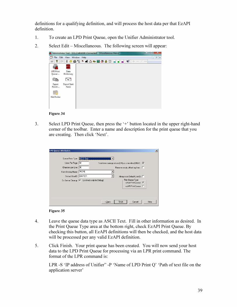
1. To create an LPD Print Queue, open the Unifier Administrator tool.
2. Select Edit – Miscellaneous. The following screen will appear:
Figure 34
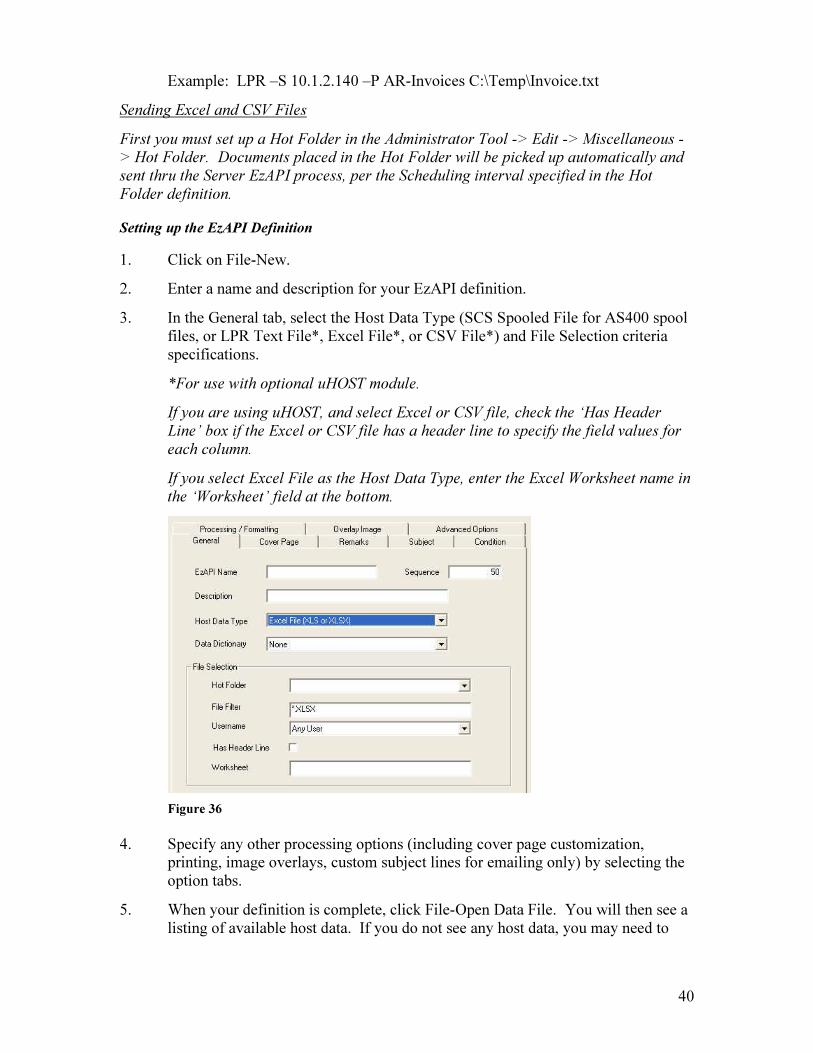
3. Select LPD Print Queue, then press the ‘+’ button located in the upper right-hand corner of the toolbar. Enter a name and description for the print queue that you are creating. Then click ‘Next’.
Figure 35
4. Leave the queue data type as ASCII Text. Fill in other information as desired. In the Print Queue Type area at the bottom right, check EzAPI Print Queue. By checking this button, all EzAPI definitions will then be checked, and the host data will be processed per any valid EzAPI definition.
5. Click Finish. Your print queue has been created. You will now send your host data to the LPD Print Queue for processing via an LPR print command. The format of the LPR command is:
LPR -S ‘IP address of Unifier” -P ‘Name of LPD Print Q’ ‘Path of text file on the application server’
40
Example: LPR –S 10.1.2.140 –P AR-Invoices C:\Temp\Invoice.txt
Sending Excel and CSV Files
First you must set up a Hot Folder in the Administrator Tool -> Edit -> Miscellaneous -
> Hot Folder. Documents placed in the Hot Folder will be picked up automatically and
sent thru the Server EzAPI process, per the Scheduling interval specified in the Hot
Folder definition.
Setting up the EzAPI Definition
1. Click on File-New.
2. Enter a name and description for your EzAPI definition.
3. In the General tab, select the Host Data Type (SCS Spooled File for AS400 spool files, or LPR Text File*, Excel File*, or CSV File*) and File Selection criteria specifications.
*For use with optional uHOST module.
If you are using uHOST, and select Excel or CSV file, check the ‘Has Header
Line’ box if the Excel or CSV file has a header line to specify the field values for
each column.
If you select Excel File as the Host Data Type, enter the Excel Worksheet name in
the ‘Worksheet’ field at the bottom.
Figure 36
4. Specify any other processing options (including cover page customization, printing, image overlays, custom subject lines for emailing only) by selecting the option tabs.
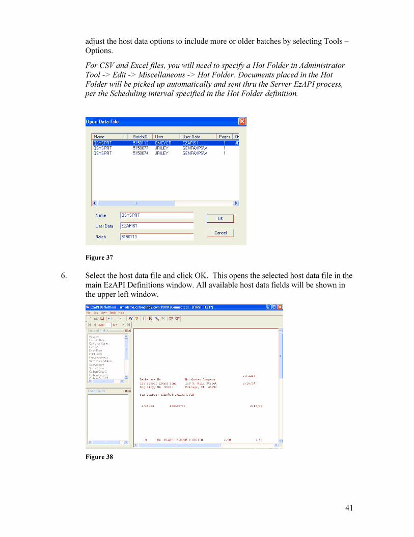
5. When your definition is complete, click File-Open Data File. You will then see a listing of available host data. If you do not see any host data, you may need to
41
adjust the host data options to include more or older batches by selecting Tools – Options.
For CSV and Excel files, you will need to specify a Hot Folder in Administrator
Tool -> Edit -> Miscellaneous -> Hot Folder. Documents placed in the Hot
Folder will be picked up automatically and sent thru the Server EzAPI process,
per the Scheduling interval specified in the Hot Folder definition.
Figure 37
6. Select the host data file and click OK. This opens the selected host data file in the main EzAPI Definitions window. All available host data fields will be shown in the upper left window.
Figure 38

42
7. Select a field from the Unused Fields window and drag it with your mouse to the corresponding field on your host data. You may resize the field to fit your host data. Repeat until all desired fields are used.
Designate the primary sending address (fax number or email address) with the Primary Address Field (this is the only required field). To enter a Constant value for the Primary Address, right click on the Primary Address field in the Unused Fields window, select Constant in the Data Source section, then enter the value and click OK.
If the Primary Address is blank on any page of host data, the Secondary Address will be used. If the primary address contains any data (valid or invalid), the secondary address is ignored.
Figure 39
For Excel and CSV files, drag the Primary Address field from the Unused Fields
window to any cell in the corresponding data column that contains destination
information. This will cause the entire column to be selected for that field value.
For files that contain a header line, the ‘Column Name’ field will be populated
with the corresponding header value of the selected column. If there is no header
line on the data file, the ‘Column Index’ field will be populated with the
corresponding number of the selected column.
If the destination address is not unique for each section of data that is to be output
for one document, you will need to select another document field that is unique to
define a Destination Break (such as Invoice Number, Customer Number, etc.).
If any column contains a blank value, and ‘Treat Blank Values as Previous Value’
is checked, the previous destination will be used.

43
Figure 40
Carbon Copy fields will allow you to send a copy of the document to that destination.
All other fields are for batch information, custom subject line (emailing only) and cover page use. Any field can be specified for use as a destination break, which means that a new document will be created based on a changed value for that field.
8. Once a field has been designated on your host data, it will appear in the Used Fields window at the bottom left.
9. When you are finished designating fields, click File-Save. The EzAPI definition is then sent to the Unifier server and you are ready to fax your documents.
Faxing EzAPI Documents
If you are faxing an AS400 spooled file, use destination *EZAPI. When the spooled file reaches the Unifier server, each EzAPI definition will be checked, in sequence order, for one that matches the selection criteria you have specified in that EzAPI definition.
If you are faxing an ASCII text file (for use with optional uHOST), send it to the LPD print queue you created using an LPR command. (For the format of the LPR command, see page 40.)
For Excel and CSV files, simply place the document(s) into the Hot Folder, specified in
the Administrator Tool -> Edit -> Miscellaneous -> Hot Folder.
Server EzAPI Monitoring Outqueue
You may set up an automatic type outqueue that directs any spoolfiles to a Server Side EzAPI definition on the Unifier server. Any spoolfile in READY status that is placed into this outqueue will get sent directly to your Unifier for processing by a valid Server EzAPI Definition.

44
• CRTOUTQ (name of outqueue), and specify DTAQ(FAXLIB/IPCPRC). SRVEZAPI in library FAXLIB is the default outqueue.
• CHGDTA XFSEZADFU to add a record to the file XFSEZAP for the outqueue you just created, or to work with the default outqueue SRVEZAPI.
• The fields in the file XFSEZAP are:
XEOUTQ Name of the Outqueue
XEOLIB Name of the Library the Outqueue is in
XELINE The FAXLINE that will be used to send to the Unifier. If
FROMUSER is entered, it will use that user's default FAXLINE
XEFRMU The username to be used when sending. *SPLF will use the
username that created the spoolfile.
XEMOVQ The name of the outqueue to move the spoolfile to after it has been
sent to the Unifier
XEMOVL The library for the outqueue specified in XEMOVQ
XEDLTS The Delete After Send parameter. If using XEMOVQ, this should
be *NO
XERELS Whether the spoolfile should be released after using XEMOVQ
XEPADR Primary address. *EZAPI should be used.
XEPCO TO COMPANY field
XEPPSN TO PERSON field
XEOVRL Image overlay to use. *FORMTYPE will use the form type of the
spoolfile as the overlay name.
XEPTY Priority

45
13. User Profile Tool The User Profile Tool allows the system administrator to create new users and user groups, to edit user profiles, and to assign policy rights (to Unifier applications) and permissions (to other users’ faxes) to users and groups. Any user who is going to send faxes from the Unifier client requires a user profile. In addition, user profiles on the Unifier are required if you are sending faxes to email addresses from the Unifier client or from the AS400. The user profile is where the sender’s email address information is specified.
As shipped, the Unifier has 2 default user profiles that can be used to log on to all Unifier applications: Admin and Unifier, with the same password. RCVUSER is used only for Port Group Table information, and is the default profile to which faxes are received for the receiving Port Group.
Two options are available for enrolling users: New User and New User Copy.
1. New User ( ): Select the New Profile icon on the toolbar. You will then see a blank user Profile Data screen. Fill it in with the appropriate user information as needed and click “Save” to update the entry.
Figure 41
2. New User Copy ( ): Select the New User Copy icon or right click in the user listing area and select New User (Copy) from the pop up menu that appears. You will then see a User Profile Data screen with fields that match the selected user’s fields. Enter the user information as needed and click ‘Save’ to update the entry.

46
Figure 42
User Profile Data - General Information
Figure 43
47
Field Descriptions
User Profile: The unique identification of the user within the Unifier system. This is how the user will log on from his PC if using Unifier logon.
User Name: The full name of the user. This information is used for the "From" information on the cover page.
Company: The name of the company. This information is used for the "From" information on the cover page.
Email Address: The email address of the user. This is used for received fax routing purposes, and is used for the “From” information on an email.
Fax Number: The fax number of the company or individual. This information is used for the "From" information on the cover page.
Phone Number: The telephone number of the company or individual. This information is used for the "From" information on the cover page.
Network User Name: Only to be used with Domain Authentication. The Domain User Name of the user.
Network Domain: Only to be used with Domain Authentication. The Domain this user is a member of.
Address: The address of the company or individual.
Change Password: Enter the password and verification (duplicate the password) for this user.
Fax Priority: The highest fax priority is 1; the lowest is 99. A queued fax with a higher priority than a processing fax will issue a Stop/Start status to the processing fax. Queued faxes begin processing in the order of priority.
Send Notification: The system may inform you as to the status of a sent message. Options are System Default, No Notifications, Failed Destinations and All Destinations. By default, batches with more than 50 destinations do not get email notifications.
Cover Page Template: The default template to be used as a cover page. This default may be changed before any fax is sent from the Assign Destinations to Fax panel.
Print Hard Copy: Determines whether a hard copy of successful faxes will be printed. This default may be changed before any fax is sent from the Assign Destinations to Fax panel.
Channel Group: The port group that will process the messages for this user. This must be a valid Fax Sending port group.
48
Printer: The user's default printer device for hard copy printouts. All installed printers will be listed in the dropdown. Select *NONE if user does not have a default printer.
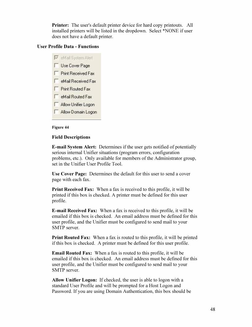
User Profile Data - Functions
Figure 44
Field Descriptions
E-mail System Alert: Determines if the user gets notified of potentially serious internal Unifier situations (program errors, configuration problems, etc.). Only available for members of the Administrator group, set in the Unifier User Profile Tool.
Use Cover Page: Determines the default for this user to send a cover page with each fax.
Print Received Fax: When a fax is received to this profile, it will be printed if this box is checked. A printer must be defined for this user profile.
E-mail Received Fax: When a fax is received to this profile, it will be emailed if this box is checked. An email address must be defined for this user profile, and the Unifier must be configured to send mail to your SMTP server.
Print Routed Fax: When a fax is routed to this profile, it will be printed if this box is checked. A printer must be defined for this user profile.
Email Routed Fax: When a fax is routed to this profile, it will be emailed if this box is checked. An email address must be defined for this user profile, and the Unifier must be configured to send mail to your SMTP server.
Allow Unifier Logon: If checked, the user is able to logon with a standard User Profile and will be prompted for a Host Logon and Password. If you are using Domain Authentication, this box should be
49
checked if the user will be logging on from a remote location as well as from your LAN.
Allow Domain Logon: If checked, the user is able to logon via the profile created from a valid domain. The user will not be prompted for a password. Leave unchecked if you are not using Domain Authentication.
13.1 Permissions Permissions are granted to users to give access to faxes, both sent and received. There are 4 levels of permissions: Everyone, Administrators, Group, and Individual Users.
Users can be assigned to Groups (for ease of maintenance), and other Groups are granted a level of access to both sent and received faxes for other Groups’ faxes. Levels of permission are:
Full Control: User may view, delete, and resend faxes.
Header Only: User can see that the fax exists in Fax Center, but cannot list destinations, view, delete, or resend faxes.
No Access: User cannot view faxes or that they even exist.
When permissions are granted at the Group level, and new users are added to that Group, the new users inherit all permissions granted to that group. No individual user permissions need to be maintained.
If a user is a member of multiple Groups, the highest level of permissions granted to that user prevails.
As shipped, the Unifier lists two Groups: Administrators and Everyone. All users are by default a member of the Everyone group, which grants all users Full Control to all other users’ faxes (this can be changed, and specific permissions can be granted). Any user added to the Administrators group will be granted Full Control to all other users’ faxes.
Restricting User Access
As shipped, the Unifier grants full authority to all users’ faxes to each user. To change this so that each user can only see his/her faxes:
1. Open the User Profile Administrator. Right click on the Everyone Group in the Group window at the bottom of the screen.
2. Click on Edit Group Permissions icon. Permissions are set for Access Sent Faxes first.
3. Highlight the Everyone Group in the Users window. Choose No Access from the Permissions dropdown at the bottom of your screen.
4. If you are receiving faxes, change the Permissions window to Access Received Faxes and repeat step 3. If you are not receiving faxes, continue with Step 5.
5. Click Save.
50
6. For Permissions changes to take effect, close the User Profile Tool or click the Refresh Permissions icon.
Now each user can only see his or her own Sent and Received faxes, unless that user has Administrative Policy Rights, or is a member of the Administrators Group.
Changing Permission Levels
In order to change Permission Levels, you must first set all users (the Everyone Group, of which all users are a member by default) to No Access. You can then create Groups and grant access to each Group’s faxes. Access may be granted to any other Group.
Note: We recommend setting Permissions at the Group level as opposed to the Individual level, for ease of maintenance. It is much easier to maintain Permissions when granted at the Group level, as users can simply be added to or deleted from a Group.
1. Open the User Profile Administrator. Right click on the Everyone Group in the Group window at the bottom of the screen.
2. Click on Edit Group Permissions. Permissions are set for Access Sent Faxes first. 3. Highlight the Everyone Group in the Users window. Choose No Access from the
Permissions dropdown at the bottom of your screen. 4. If you are receiving faxes, change the Permissions window to Access Received Faxes
and repeat step 3. 5. Click Save. 6. For Permissions changes to take effect, close the User Profile Tool or click the
Refresh Permissions icon.
Now that the Everyone Group has been changed to No Access for both Sent and Received faxes, you can set Permissions for other Groups as needed.
Creating Groups
Open the User Profile Administrator. Click the New Group icon ( ).
1. Enter the name of the Group and a description.
2. Click on Add to view a list of currently enrolled users.
3. Highlight a user and click Add, or to select multiple users, hold Ctrl and highlight users, then click Add. These names will then appear in the Add Names window.
4. Click OK.

51
Setting Permissions for Other Groups
1. Complete steps 1-5 above under Changing Permission Levels.
2. Right click on Group A in the Group window at the bottom of the User Profile Administrator screen.
3. Click on Edit Group Permissions. Permissions are set for Access Sent Faxes first.
4. Click on Add, and highlight Group B from the dropdown. Click OK.
5. Click on Group B in the Users window, and choose the level of permission desired (Header Only or Full Control) for Group B.
6. Change the Permissions window to Access Received Faxes and repeat step 5.
7. Click Save. You have now granted Group B a level of permission for access to Group A’s faxes.
8. For Permissions changes to take effect, close the User Profile Tool or click the Refresh Permissions icon.
13.2 Policy Rights Policy Rights are granted to users and groups to give access to individual Unifier features, including access to utilities, cover pages, address books, and password options. If a particular user cannot access a feature from a workstation, check that user’s Policy Rights for that feature.
Any user who has been granted Administrator Rights has full access to all Sent and Received faxes, as well as full permissions to everything listed in the Policy Rights dropdown.
Granting Policy Rights
1. Open the User Profile Administrator. Click Policies, then User Rights.
2. Select the feature to which you are granting user access from the Rights dropdown.
Figure 45
3. Click Add to view a list of currently enrolled users.
52
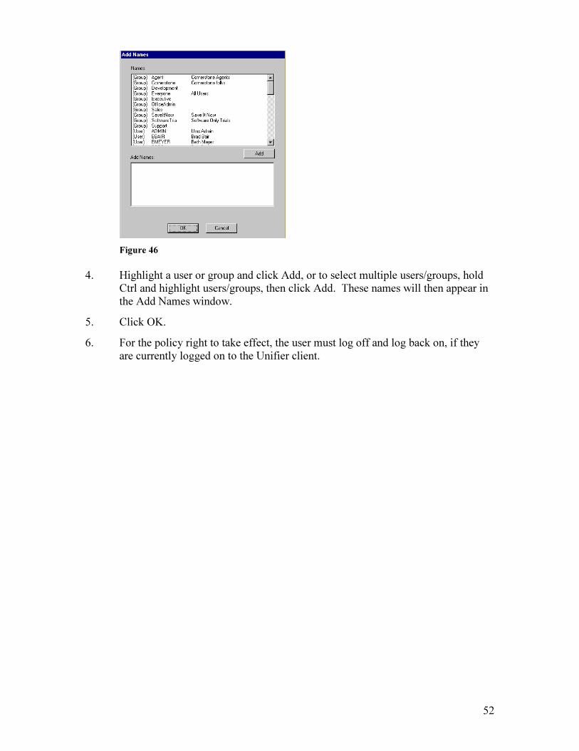
Figure 46
4. Highlight a user or group and click Add, or to select multiple users/groups, hold Ctrl and highlight users/groups, then click Add. These names will then appear in the Add Names window.
5. Click OK.
6. For the policy right to take effect, the user must log off and log back on, if they are currently logged on to the Unifier client.
53
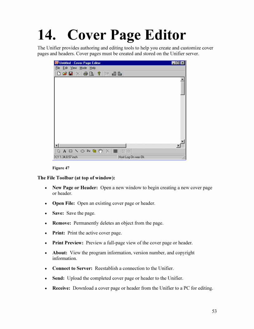
14. Cover Page Editor The Unifier provides authoring and editing tools to help you create and customize cover pages and headers. Cover pages must be created and stored on the Unifier server.
Figure 47
The File Toolbar (at top of window):
• New Page or Header: Open a new window to begin creating a new cover page or header.
• Open File: Open an existing cover page or header.
• Save: Save the page.
• Remove: Permanently deletes an object from the page.
• Print: Print the active cover page.
• Print Preview: Preview a full-page view of the cover page or header.
• About: View the program information, version number, and copyright information.
• Connect to Server: Reestablish a connection to the Unifier.
• Send: Upload the completed cover page or header to the Unifier.
• Receive: Download a cover page or header from the Unifier to a PC for editing.
54
The Design Toolbar (at bottom of window):
• Pointer: Select an object.
• Text: Create or edit a text box.
• Rectangle: Create or edit a rectangle object.
• Line: Create a line object.
• Ellipse: Create an ellipse object.
• Picture: Insert a PCX image into the cover page.
• Message Box: Create an area that will hold the text of the message.
• Move: Reposition an object.
• Remove: Permanently delete an object.
• Snap to Grid: Use for uniform alignment of objects.
• Center Vertically: Place an object the same distance from the top and bottom of the page.
• Center Horizontally: Place an object the same distance from the left and right sides of the page.
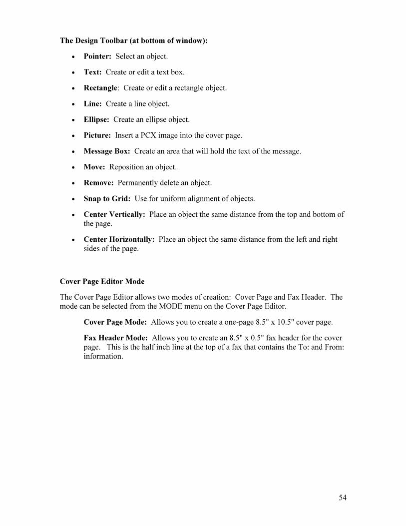
Cover Page Editor Mode
The Cover Page Editor allows two modes of creation: Cover Page and Fax Header. The mode can be selected from the MODE menu on the Cover Page Editor.
Cover Page Mode: Allows you to create a one-page 8.5" x 10.5" cover page.
Fax Header Mode: Allows you to create an 8.5" x 0.5" fax header for the cover page. This is the half inch line at the top of a fax that contains the To: and From: information.
55
Figure 48
The screen above indicates the Editor is in Fax Header mode. The white area is a half-inch high area. (Note that the Message Box tool is not available in this mode.)
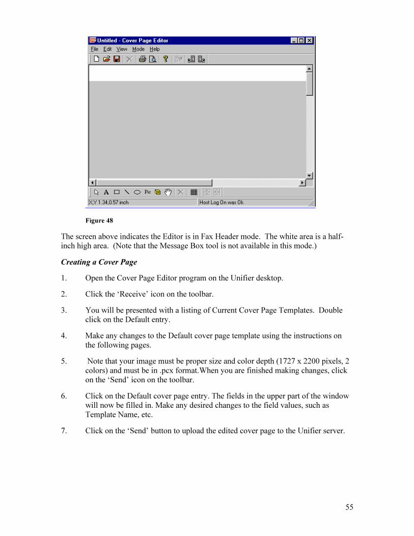
Creating a Cover Page
1. Open the Cover Page Editor program on the Unifier desktop.
2. Click the ‘Receive’ icon on the toolbar.
3. You will be presented with a listing of Current Cover Page Templates. Double click on the Default entry.
4. Make any changes to the Default cover page template using the instructions on the following pages.
5. Note that your image must be proper size and color depth (1727 x 2200 pixels, 2 colors) and must be in .pcx format.When you are finished making changes, click on the ‘Send’ icon on the toolbar.
6. Click on the Default cover page entry. The fields in the upper part of the window will now be filled in. Make any desired changes to the field values, such as Template Name, etc.
7. Click on the ‘Send’ button to upload the edited cover page to the Unifier server.
56
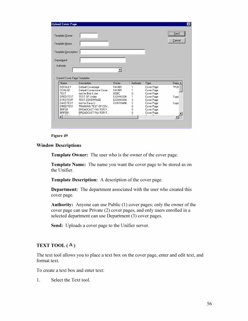
Figure 49
Window Descriptions
Template Owner: The user who is the owner of the cover page.
Template Name: The name you want the cover page to be stored as on the Unifier.
Template Description: A description of the cover page.
Department: The department associated with the user who created this cover page.
Authority: Anyone can use Public (1) cover pages; only the owner of the cover page can use Private (2) cover pages, and only users enrolled in a selected department can use Department (3) cover pages.
Send: Uploads a cover page to the Unifier server.
TEXT TOOL ( )
The text tool allows you to place a text box on the cover page, enter and edit text, and format text.
To create a text box and enter text:
1. Select the Text tool.
57
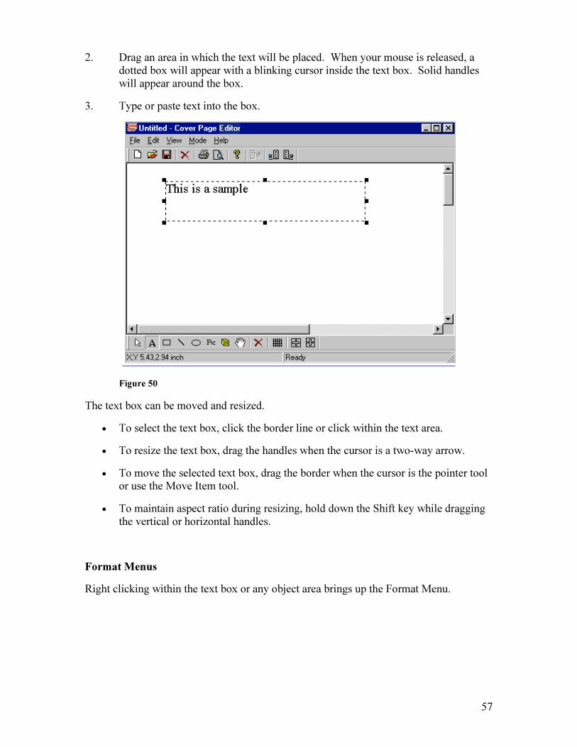
2. Drag an area in which the text will be placed. When your mouse is released, a dotted box will appear with a blinking cursor inside the text box. Solid handles will appear around the box.
3. Type or paste text into the box.
Figure 50
The text box can be moved and resized.
• To select the text box, click the border line or click within the text area.
• To resize the text box, drag the handles when the cursor is a two-way arrow.
• To move the selected text box, drag the border when the cursor is the pointer tool or use the Move Item tool.
• To maintain aspect ratio during resizing, hold down the Shift key while dragging the vertical or horizontal handles.
Format Menus
Right clicking within the text box or any object area brings up the Format Menu.

58
Figure 51
Many objects can be overlapped and rearranged by using the Placement Commands. To bring an object forward in the deck, click the Move to Front. To send an object down in the deck, use Move to Back. The principal of layering (placing an object on top of or behind another object) is applicable to the following objects: textbox, rectangle, line, ellipse, picture, and message box.
Font Size and Style
This is a listing of fonts stored on the Unifier server. If you have special fonts you would like to use, install them on the Unifier server.
Figure 52
1. Select the text that is to be formatted.

59
2. Choose Font from the Text Format menu
3. Select the font, style, size and effect to be used.
4. Click OK.
Text Alignment
Figure 53
• Left: Left justify the text.
• Center: Center the text in the text box.
• Right: Right justify the text in the text box.
Inserting a Field
Cover Page Editor provides a list of recipient and sender fields to include on your pages. The field values will be filled in based on the user profile of the sender.
60
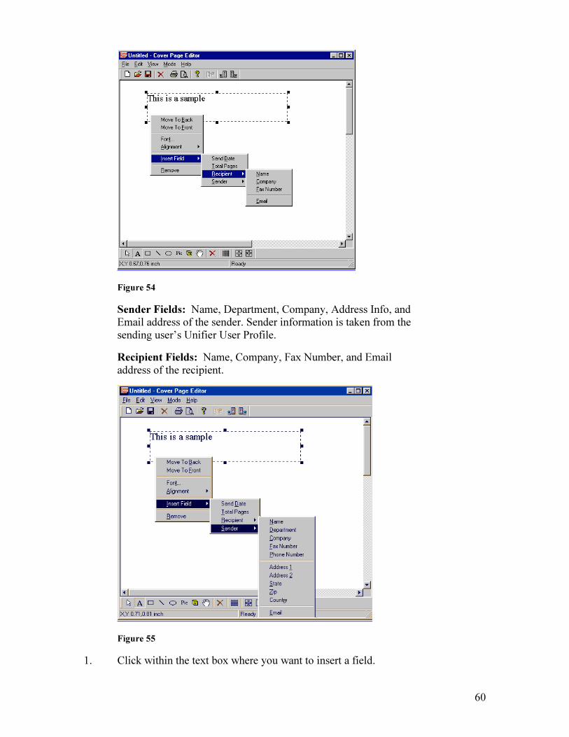
Figure 54
Sender Fields: Name, Department, Company, Address Info, and Email address of the sender. Sender information is taken from the sending user’s Unifier User Profile.
Recipient Fields: Name, Company, Fax Number, and Email address of the recipient.
Figure 55
1. Click within the text box where you want to insert a field.

61
2. Choose the field to insert from the dropdown.
RECTANGLE TOOL ( )
To create a rectangle:
1. Select the Rectangle tool.
2. Drag an area for the rectangle to be placed. When the mouse is released, the rectangle will appear with dotted lines around the outside. Solid handles will appear around the rectangle.
3. To resize the rectangle, drag the handles when the cursor is a two-way arrow.
4. To end the creation and resizing of the current rectangle, select another object, select another tool to use, or create the same object by repeating steps 2 and 3.
Figure 56
The Rectangle can be moved and resized like other tools of the Cover Page Editor. To maintain the aspect ratio during resizing, hold down the Shift key while dragging the vertical or horizontal handles.
LINE TOOL ( )
To create a Line:
1. Select the Line tool.
2. Drag an area for the line to be placed. When the mouse is released, the Line will appear with solid handles at both ends of the Line.
62
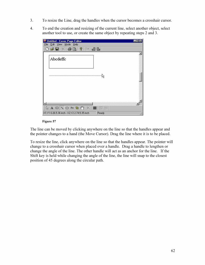
3. To resize the Line, drag the handles when the cursor becomes a crosshair cursor.
4. To end the creation and resizing of the current line, select another object, select another tool to use, or create the same object by repeating steps 2 and 3.
Figure 57
The line can be moved by clicking anywhere on the line so that the handles appear and the pointer changes to a hand (the Move Cursor). Drag the line where it is to be placed.
To resize the line, click anywhere on the line so that the handles appear. The pointer will change to a crosshair cursor when placed over a handle. Drag a handle to lengthen or change the angle of the line. The other handle will act as an anchor for the line. If the Shift key is held while changing the angle of the line, the line will snap to the closest position of 45 degrees along the circular path.

63
Line Format Menu
Figure 58
Right clicking on the Line brings up the Line Format Menu.
ELLIPSE TOOL ( )
To create an Ellipse:
1. Select the Ellipse tool.
2. Drag an area where you want the ellipse to be placed. When the mouse is released, an ellipse will appear with solid handles around it.
3. To resize the ellipse, drag the handles when the cursor is a two-way arrow.
4. To end the creation and resizing of the current ellipse, select another object, select another tool to use, or create the same object by repeating steps 2 and 3.

64
Figure 59
The ellipse can be moved and resized like other tools of the Cover Page Editor. To maintain the aspect ratio during resizing, hold down the Shift key while dragging the vertical or horizontal handles.
Ellipse Format Menu
Figure 60
Right clicking within the ellipse area brings up the Ellipse Format Menu.

65
PICTURE TOOL ( )
To place a PCX image on a cover page:
1. Select the Pic tool.
2. Drag an area with your mouse in which the image will be placed. When your mouse is released, the Open dialog box appears:
Figure 61
3. Select the image to be placed on the cover page. Remember that the image must be a true black and white image (2 colors) and must be in PCX format. Click Open.
4. If the image is not the correct size or color depth, the image will not appear on your cover page template. Check the size and color depth of the image, and correct it.
Figure 62

66
4. To resize the Image, drag the handles when the cursor is a two-way arrow.
5. To end the creation and resizing of the current image, select another object, select another tool to use, or create the same object by repeating steps 2 and 3.
Right clicking on the image brings up the Image Format Menu.
Figure 63
Image Selection & Sizing:
• Image File: Allows another image to be placed within the picture area. This will delete the prior image and replace it with the newly selected image.
• Fit to Width: Resize an image window so that it fits the width of the image.
• Fit to Height: Resize an image window so that it fits the height of the image. To maintain the aspect ratio during resizing, hold down the Shift key while dragging the vertical or horizontal handle.
MESSAGE BOX TOOL ( )
The Message Box is the area where cover page remarks or the text of a Quick Note will be positioned. Only one Message Box can be placed on a cover page.
1. Select the Message Box tool.
2. Drag an area with your mouse for the message to be placed. When your mouse is released, the Message box appears:

67
Figure 64
3. Click the Message Box tool again to end the creation and resizing of the message area. To resize the Message Area, drag the handles when the cursor is a two-way arrow. To maintain the aspect ratio during resizing, hold down the Shift key while dragging the vertical or horizontal handles.
Message Format Menu
Figure 65
Right clicking within the message box area brings up the Message Box Format Menu.

68
Font Size & Style
Figure 66
1. Choose Font from the Text Format menu.
2. Select the font, style, size and effect to be used.
3. Click OK.
MOVE ITEM TOOL ( )
This tool gives the user control of the placement of objects on the cover page.
1. Select the Move Item Tool.
2. When the cursor is over an object it will change to a pointing hand. Click the object of choice. The pointing hand will change to an open hand. Handles will appear around the object.
3. Drag the object to where it is to be placed and release the mouse. The handles will stay active on the selected object.

69
Figure 67
While simply selecting and dragging to the new location can move most of the objects, the Text Box object is unique. By selecting the text box object, the text box is placed in a text entry mode, which does not lend itself to the movement of the object. Using the Move Item tool is the only way to quickly select and move a text box without the text box going into text entry mode.
REMOVE TOOL ( )
1. When the cursor is over an object it will change to a pointing hand. Click the object to be deleted. The pointing hand will change to an open hand, and handles will appear around the object.
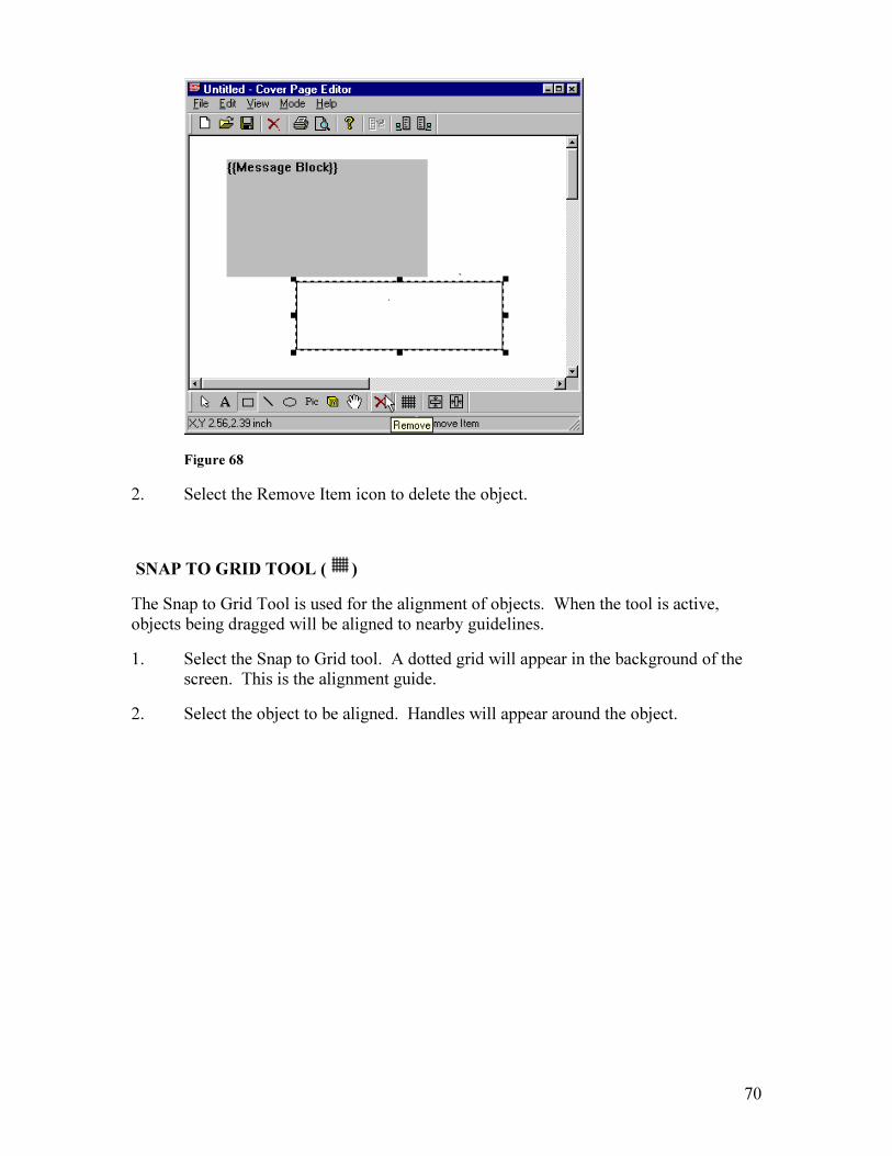
70
Figure 68
2. Select the Remove Item icon to delete the object.
SNAP TO GRID TOOL ( )
The Snap to Grid Tool is used for the alignment of objects. When the tool is active, objects being dragged will be aligned to nearby guidelines.
1. Select the Snap to Grid tool. A dotted grid will appear in the background of the screen. This is the alignment guide.
2. Select the object to be aligned. Handles will appear around the object.

71
Figure 69
3. Moving any handle with the grid active will align the object vertically and horizontally to the nearest guide when the resize is completed. For the line object, both endpoints will be at a guide point on the grid.
The Snap to Grid can remain active during the cover page creation process. This will make it easy to align the elements to the cover page. Selecting the Snap to Grid tool again will deactivate it.
CENTERING TOOL
The Cover Page Editor provides two tools to use in the centering of objects on the cover page:
Vertical Centering ( ): The object will be the same distance from the top and bottom of the page.
Horizontal Centering ( ): The object will be the same distance from the left and right edges of the page.

72
Vertical Centering
1. Select the object to center.
Figure 70
2. Select the Center Vertical icon. The object is centered on the page vertically, not on the window you see.
3. Using Print Preview from the File menu, the position of the object is revealed.
Horizontal Centering
1. Select the object to center.
2. Select the Center Horizontal icon. The object is centered on the page horizontally, not on the window you see.
3. Using Print Preview from the File menu, the position of the object is revealed.
To place an object in the exact center of the page, combine the vertical and horizontal centering icons.
73
15. Administrator Tool The Administrator Tool represents a suite of applications that the Unifier administrator(s) can utilize to perform system management.
• CSID Routing ( ): Allows routing of incoming faxes based on the sending fax machine’s identification.
• DID Routing ( ): Allows routing of incoming faxes based on Direct Inward Dialing.
• Domain Authentication ( ): Allows automatic enrollment of users based on your company’s Domain membership.
• DTMF Routing ( ): Allows routing of incoming faxes based on DTMF digits sent by a PBX or entered manually by the sender.
• Foreign Address Source Association ( ): Notifies the Unifier client about alternate address book associations such as ODBC or Lotus Notes.
• Foreign Database ( ): Allows fax users to use their existing customer, contact or vendor files resident on the AS400 when selecting fax destinations and creating fax call groups.
• Local/Long Distance ( ): A listing of dialing exceptions for local area codes and extensions.
• Port/Port Group Table ( ): Allows management and assignment of fax ports.
• Printer Alias ( ): Assigns short alias names to network printers for AS400 reference only.
• System Backup/Redundancy ( ): Allows scheduling and management of system backup, as well as redundancy (file copy) option for multiple Unifier environments.
• Restore from Backup ( ): Allows Unifier faxes and configuration files to be restored from a backup location.
• Miscellaneous ( ): Several tools are managed from this option:
LPD Print Queue: (Requires the optional uHOST module) LPD Print Queue allows Unifier to be defined as an LPD/LPR print queue for use with any operating system that supports LPD/LPR printing.
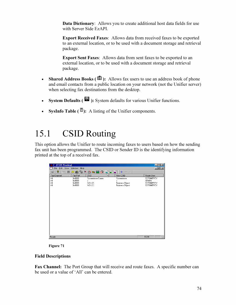
74
Data Dictionary: Allows you to create additional host data fields for use with Server Side EzAPI.
Export Received Faxes: Allows data from received faxes to be exported to an external location, or to be used with a document storage and retrieval package.
Export Sent Faxes: Allows data from sent faxes to be exported to an external location, or to be used with a document storage and retrieval package.
• Shared Address Books ( ): Allows fax users to use an address book of phone and email contacts from a public location on your network (not the Unifier server) when selecting fax destinations from the desktop.
• System Defaults ( ): System defaults for various Unifier functions.
• SysInfo Table ( ): A listing of the Unifier components.
15.1 CSID Routing This option allows the Unifier to route incoming faxes to users based on how the sending fax unit has been programmed. The CSID or Sender ID is the identifying information printed at the top of a received fax.
Figure 71
Field Descriptions
Fax Channel: The Port Group that will receive and route faxes. A specific number can be used or a value of ‘All’ can be entered.

75
Fax Port: The Port that will receive and route faxes. A specific port number can be entered or a value of 0x0000 can be entered.
CSID: The identifying numbers or characters displayed at the top of every fax in the ‘From’ field as programmed into the sending fax unit. You must enter the CSID exactly as it appears at the top of a received fax.
New CSID: This field allows the user to request Unifier to automatically change a CSID (such as a fax number) to a more meaningful entry (such as a company name).
Route User: The fax user profile to which any fax associated with this CSID will be routed. After an incoming fax is identified based on the Sender ID, Unifier automatically routes the received fax to this user.
15.2 DID Routing Requires DID or digital faxboard and DID service from your telephone provider
DID (Direct Inward Dialing) routing enables inbound faxes to an individual user. For this feature to work, you must have either a DID or digital board installed in your Unifier. Also, you must contact your phone provider for DID service. (Unifier checks for routing entries in the following order: DID, DTMF, CSID, default routing specified for that channel group.)
Figure 72
Field Descriptions
Fax Channel: The Port Group that will receive and route faxes. A specific number can be used or a value of “All” can be entered.
76
Fax Port: The Port that will receive and route faxes. A specific port number can be entered or a value of 0x0000 can be entered.
DID: The DID number that is being used for routing.
Route User: The Unifier user profile that a received fax will be routed to when a match occurs on the DID string.
15.3 Domain Authentication Domain Authentication allows the system administrator to set up trusted domains on the Unifier system for automatic creation of Unifier user profiles, and allows users to log on without inputting a username or password.
When Domain Authentication Auto Enroll is enabled in the System Defaults (System Information window), if a client connects to the Unifier and the client is logged onto an approved domain with an approved IP address, Unifier will automatically create a user record for the client, and no password is required for logon. The Unifier user profile name will be based on the domain user name, and the user defaults will be based on a Model Profile created by the administrator (note that the username may be truncated). The administrator can then edit each automatically created profile, if necessary.
Authentication can be set to a Range (or multiple ranges) of IP addresses for authentication, or a Mask, which will allow authentication for a complete range of IP addresses.
Each Unifier user profile (in the Unifier User Profile Tool) must be edited to specify a domain logon. Domain Authentication must also be enabled in Fax Center on each client PC.
Creating a Model Profile
1. Open the User Profile Administrator on the Unifier desktop.
2. Create a New User profile with the desired defaults for new users.
Enabling Domain Authentication
1. Open the Administrator Tool on the Unifier desktop. Click on Edit-System Defaults, then select System Information. Click the ‘Enable Domain Authentication’ box. Click Save Changes.
2. Click Edit-Domain Authentication. You will see the following window:
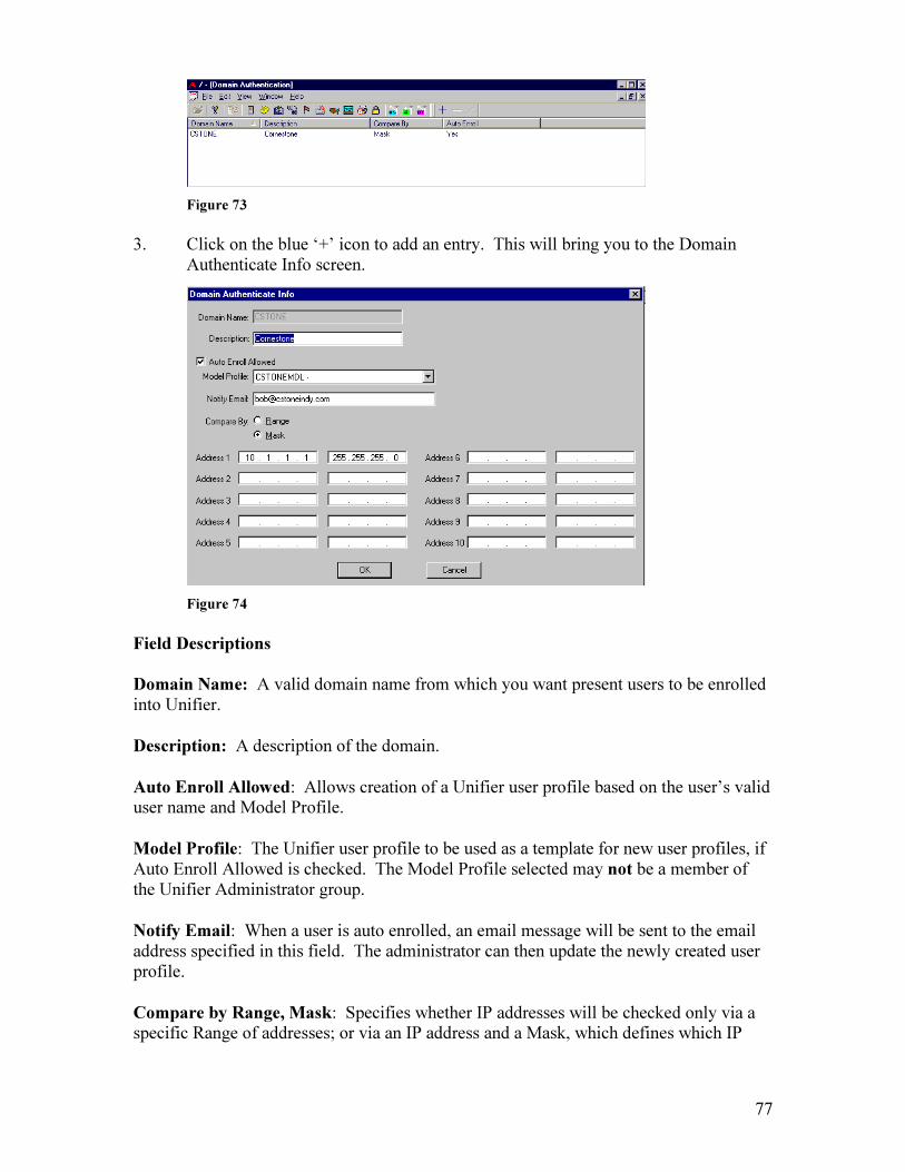
77
Figure 73
3. Click on the blue ‘+’ icon to add an entry. This will bring you to the Domain Authenticate Info screen.
Figure 74
Field Descriptions
Domain Name: A valid domain name from which you want present users to be enrolled into Unifier.
Description: A description of the domain.
Auto Enroll Allowed: Allows creation of a Unifier user profile based on the user’s valid user name and Model Profile.
Model Profile: The Unifier user profile to be used as a template for new user profiles, if Auto Enroll Allowed is checked. The Model Profile selected may not be a member of the Unifier Administrator group.
Notify Email: When a user is auto enrolled, an email message will be sent to the email address specified in this field. The administrator can then update the newly created user profile.
Compare by Range, Mask: Specifies whether IP addresses will be checked only via a specific Range of addresses; or via an IP address and a Mask, which defines which IP
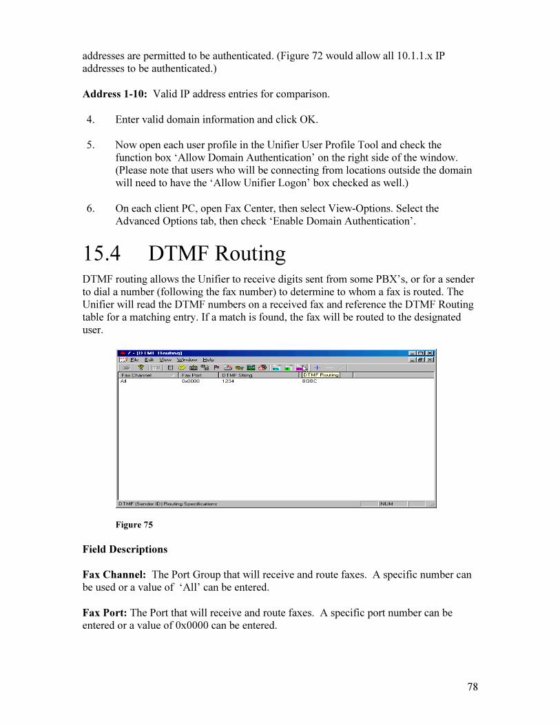
78
addresses are permitted to be authenticated. (Figure 72 would allow all 10.1.1.x IP addresses to be authenticated.)
Address 1-10: Valid IP address entries for comparison.
4. Enter valid domain information and click OK.
5. Now open each user profile in the Unifier User Profile Tool and check the function box ‘Allow Domain Authentication’ on the right side of the window. (Please note that users who will be connecting from locations outside the domain will need to have the ‘Allow Unifier Logon’ box checked as well.)
6. On each client PC, open Fax Center, then select View-Options. Select the Advanced Options tab, then check ‘Enable Domain Authentication’.
15.4 DTMF Routing DTMF routing allows the Unifier to receive digits sent from some PBX’s, or for a sender to dial a number (following the fax number) to determine to whom a fax is routed. The Unifier will read the DTMF numbers on a received fax and reference the DTMF Routing table for a matching entry. If a match is found, the fax will be routed to the designated user.
Figure 75
Field Descriptions
Fax Channel: The Port Group that will receive and route faxes. A specific number can be used or a value of ‘All’ can be entered.
Fax Port: The Port that will receive and route faxes. A specific port number can be entered or a value of 0x0000 can be entered.

79
DTMF String: A DTMF string is sent by a PBX or dialed by the sender. If a received fax contains this DTMF string, the fax will automatically be routed to the user associated with this string.
Route to User: The user who will receive the routed fax. Please note that the user’s profile (in the User Profile Tool) must be edited to allow emailing of routed faxes (the function box ‘Email Routed Fax’ on that user’s profile must be checked).
15.5 Foreign Address Source Association Foreign Address Source Association allows fax users to use existing customer, contact or vendor address books when selecting fax destinations. Any address book on your network can be defined to Unifier, making it accessible from fax applications. A lookup list program is provided for easy record selection. Records from the foreign file may be displayed by selecting the display option from the lookup lists.
Note: The DSN must be set up on individual workstations prior to setting up the Address Source on the Unifier server side. ODBC drivers and DSN must exist on each workstation as well as on the Administrator’s workstation.
Creating an ODBC Address Source
1. Select the Address Source Association icon.
Figure 76
2. Select the Source Association icon (the 2 open books with the yellow star).

80
Figure 77
3. Click ‘New’. The Source Type window will appear.
Figure 78
4. Complete the screen and click ‘Next’. The following screens allow you to select a source format, database table, and make column assignments. Once the Association is saved to the table listing, the members of the database can be selected from the Assign Destinations to Fax screen.
5. Please note that access to ODBC Address Books is a Policy Right, and the policy right must be granted to all users who require access.
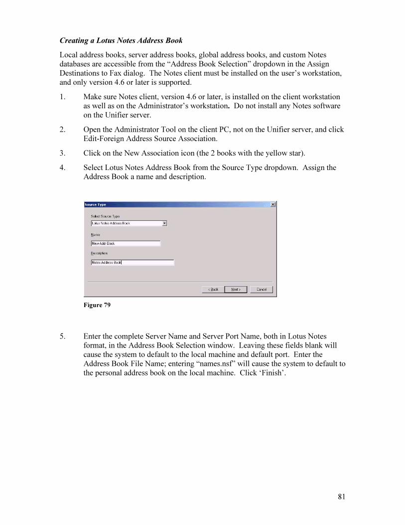
81
Creating a Lotus Notes Address Book
Local address books, server address books, global address books, and custom Notes databases are accessible from the “Address Book Selection” dropdown in the Assign Destinations to Fax dialog. The Notes client must be installed on the user’s workstation, and only version 4.6 or later is supported.
1. Make sure Notes client, version 4.6 or later, is installed on the client workstation as well as on the Administrator’s workstation. Do not install any Notes software on the Unifier server.
2. Open the Administrator Tool on the client PC, not on the Unifier server, and click Edit-Foreign Address Source Association.
3. Click on the New Association icon (the 2 books with the yellow star).
4. Select Lotus Notes Address Book from the Source Type dropdown. Assign the Address Book a name and description.
Figure 79
5. Enter the complete Server Name and Server Port Name, both in Lotus Notes format, in the Address Book Selection window. Leaving these fields blank will cause the system to default to the local machine and default port. Enter the Address Book File Name; entering “names.nsf” will cause the system to default to the personal address book on the local machine. Click ‘Finish’.

82
Figure 80
6. End and restart the Unifier client. This creates the entry on the Unifier server.
Entering a Lotus Notes Database
1. Make sure Notes client, version 4.6 or later, is installed on the client. Do not install any Notes software on the Unifier server.
2. Open the Administrator Tool on the client PC, not on the Unifier server, and click on Edit-Foreign Address Source Association.
3. Click on the New Association icon (the 2 books with the yellow star).
4. Select Lotus Notes Database from the Source Type dropdown. Enter the Database name and description and click ‘Next’.
Figure 81
5. Enter the complete Server Name and Server Port Name in the Database File Selection window. Leaving these fields blank will cause the system to default to the local machine and default port. Enter the Database File Name; there is no default entry for this field, and click ‘Next’.
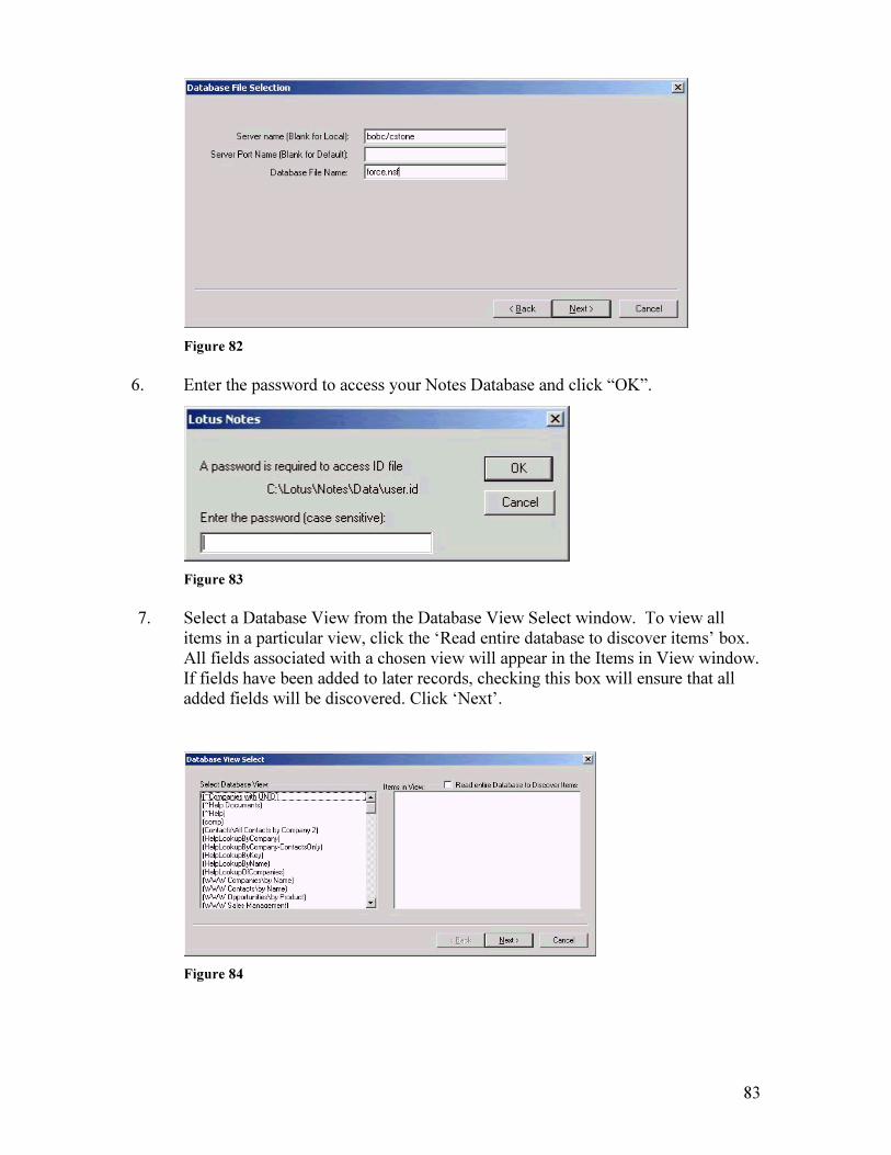
83
Figure 82
6. Enter the password to access your Notes Database and click “OK”.
Figure 83
7. Select a Database View from the Database View Select window. To view all items in a particular view, click the ‘Read entire database to discover items’ box. All fields associated with a chosen view will appear in the Items in View window. If fields have been added to later records, checking this box will ensure that all added fields will be discovered. Click ‘Next’.
Figure 84

84
8. In the Column Assignment window, select a Notes Item, then double click on the appropriate Unifier Field to associate the fields. When you are finished, click ‘Finish’.
Figure 85
15.6 Foreign Database Foreign Database allows users to use existing customer, contact or vendor files when selecting fax destinations. Any database file existing on the AS400 can be defined to Unifier in minutes, after which the file is accessible from fax applications. A lookup list program is provided for easy record selection. Records from the database may be displayed by selecting the display option from the lookup lists.
The Foreign Database must be defined to the Unifier400 prior to the attempt to link it with the server side. See the chapter on Customizing Database Options in the Unifier400 Manual for details.
1. To link a Foreign Database to the Unifier system, select the Foreign Database icon (the flag) within the Administrator Tool. This brings you to the Foreign Database Table.
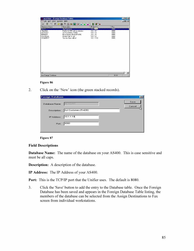
85
Figure 86
2. Click on the ‘New’ icon (the green stacked records).
Figure 87
Field Descriptions
Database Name: The name of the database on your AS400. This is case sensitive and must be all caps.
Description: A description of the database.
IP Address: The IP Address of your AS400.
Port: This is the TCP/IP port that the Unifier uses. The default is 8080.
3. Click the 'Save' button to add the entry to the Database table. Once the Foreign Database has been saved and appears in the Foreign Database Table listing, the members of the database can be selected from the Assign Destinations to Fax screen from individual workstations.
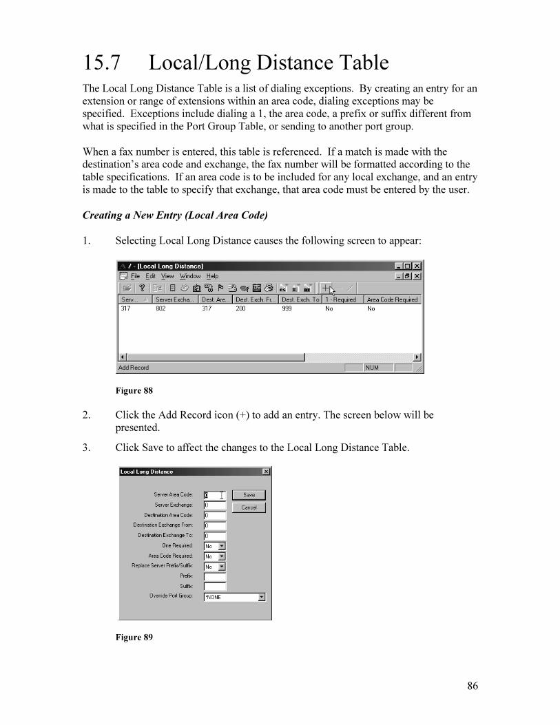
86
15.7 Local/Long Distance Table The Local Long Distance Table is a list of dialing exceptions. By creating an entry for an extension or range of extensions within an area code, dialing exceptions may be specified. Exceptions include dialing a 1, the area code, a prefix or suffix different from what is specified in the Port Group Table, or sending to another port group.
When a fax number is entered, this table is referenced. If a match is made with the destination’s area code and exchange, the fax number will be formatted according to the table specifications. If an area code is to be included for any local exchange, and an entry is made to the table to specify that exchange, that area code must be entered by the user.
Creating a New Entry (Local Area Code)
1. Selecting Local Long Distance causes the following screen to appear:
Figure 88
2. Click the Add Record icon (+) to add an entry. The screen below will be presented.
3. Click Save to affect the changes to the Local Long Distance Table.
Figure 89

87
Field Descriptions
Server Area Code: The area code local to the Unifier server. This number must match what is in the Port Group Table.
Server Exchange: The exchange of the phone line the Unifier server is plugged into.
Destination Area Code: The destination area code that requires special dialing instructions.
Destination Exchange From: The beginning range of the exchange.
Destination Exchange To: The ending exchange of the range.
One Required: Determines whether to keep or omit the leading '1' when dialing numbers with this area code/exchange. If 'Yes', the leading '1' will be left in the fax number or added if it is not already there. If 'No', the leading '1' will be stripped from the fax number.
Area Code Required: Determines whether to include the area code when dialing numbers with this area code/exchange. If 'Yes', the area code will be left in the fax number. If 'No', the area code will be stripped from the fax number.
Replace Server Prefix/Suffix: If set to ‘Yes’, the prefix and suffix from the Port Group Table will be ignored and only the prefix/suffix specified in the Local Long Distance Table will be used.
Prefix: Number that will be dialed before the fax number.
Suffix: String that will be added to the end of the fax number, such as an access code. You will need to add one or more commas before the suffix to designate a pause of one second per comma.
Override Port Group: Default is *None. Update to another send port group if you want to use a port group other than the default.
Note: The information in this table represents area codes and exchanges that are considered local in reference to the Unifier server. If the exchange or area code is not listed in this table, the number will be considered long distance.
15.8 Port/Port Group Table The levels of the system are Port Group (a grouping of available ports), System (a declared subset of ports within a Channel), and Port (an actual line of transmission).
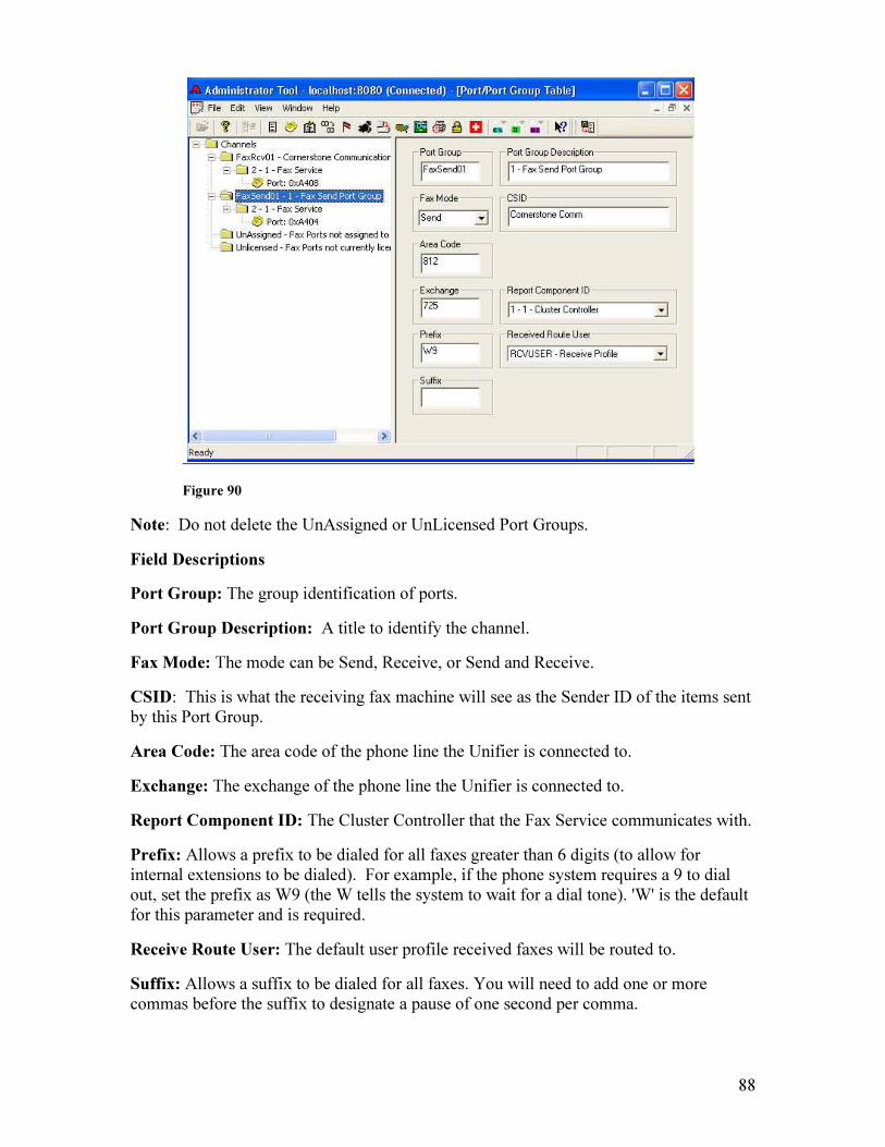
88
Figure 90
Note: Do not delete the UnAssigned or UnLicensed Port Groups.
Field Descriptions
Port Group: The group identification of ports.
Port Group Description: A title to identify the channel.
Fax Mode: The mode can be Send, Receive, or Send and Receive.
CSID: This is what the receiving fax machine will see as the Sender ID of the items sent by this Port Group.
Area Code: The area code of the phone line the Unifier is connected to.
Exchange: The exchange of the phone line the Unifier is connected to.
Report Component ID: The Cluster Controller that the Fax Service communicates with.
Prefix: Allows a prefix to be dialed for all faxes greater than 6 digits (to allow for internal extensions to be dialed). For example, if the phone system requires a 9 to dial out, set the prefix as W9 (the W tells the system to wait for a dial tone). 'W' is the default for this parameter and is required.
Receive Route User: The default user profile received faxes will be routed to.
Suffix: Allows a suffix to be dialed for all faxes. You will need to add one or more commas before the suffix to designate a pause of one second per comma.
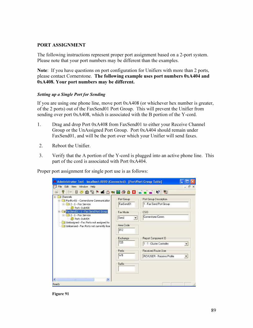
89
PORT ASSIGNMENT
The following instructions represent proper port assignment based on a 2-port system. Please note that your port numbers may be different than the examples.
Note: If you have questions on port configuration for Unifiers with more than 2 ports, please contact Cornerstone. The following example uses port numbers 0xA404 and 0xA408. Your port numbers may be different.
Setting up a Single Port for Sending
If you are using one phone line, move port 0xA408 (or whichever hex number is greater, of the 2 ports) out of the FaxSend01 Port Group. This will prevent the Unifier from sending over port 0xA408, which is associated with the B portion of the Y-cord.
1. Drag and drop Port 0xA408 from FaxSend01 to either your Receive Channel Group or the UnAssigned Port Group. Port 0xA404 should remain under FaxSend01, and will be the port over which your Unifier will send faxes.
2. Reboot the Unifier.
3. Verify that the A portion of the Y-cord is plugged into an active phone line. This part of the cord is associated with Port 0xA404.
Proper port assignment for single port use is as follows:
Figure 91

90
Setting up Two Ports for Sending
If you are using two phone lines, and you wish to send over both phone lines, leave both ports under FaxSend01, and plug both ends of the Y-cord (A and B) into the phone lines.
Setting up One Port for Sending and One Port for Receiving
If you are using two phone lines, and you wish to send over one line and receive over the other line, move Port 0xA408 to your Receiving Port Group.
1. Click and drag Port 0xA408 from FaxSend01 to FaxRcv01. You will see a subfolder with your port group description under ‘FaxRcv01’. The port goes directly under the subfolder.
2. Reboot the Unifier.
3. Verify that both portions of the Y-cord are plugged into active phone lines (for a 2-line system).
Proper port assignment for one sending port and one receiving port is as follows:
Figure 92
Routing Received Faxes to an Email Address
1. In the User Profile Tool, create a default user profile for received faxes.
2. In the email field in the user profile, specify an email address (or addresses) to which you want incoming faxes to be routed.

91
3. In the Port Group Table, click on your Receiving Port Group (FaxRcv01).
4. In the Received Route User field, select the default profile you created in Step 1 above from the dropdown menu. Exit and save the changes to the Port Group data.
5. Reboot the Unifier.
15.9 Printer Alias Assigning a Printer Alias allows printers on your network to be recognized by the AS400 only. It is not required for printing from Windows.
1. Click on the Printer Alias icon (printer with the question mark), or click Edit-Printer Alias.
2. Type in an alias (8 characters or less) for any printer you have installed on your Unifier, which will appear in the Printers dropdown. (If the printer does not show up after install, please make sure you have installed the latest drive, that you can print a test page, and that you have rebooted the Unifier.) This alias must now be entered on the Unifier400 user profile of any user who wishes to print to this printer.
Figure 93
Window Descriptions
Printers: The printer name as it is installed on the Unifier. If the printer does not appear in this drop-down listing after the printer driver has been installed on the Unifier server, reboot the Unifier. Note that the printer name cannot exceed 40 characters.

92
Alias: This is the name that the AS/400 will use when referring to the listed printer. This name must be eight characters or less to be recognized by your AS400.
Allow Direct uFORMz Print: Used for Hard Copy Only option with (optional) uFORMz.
15.10 System Backup/Redundancy The Unifier System Backup backs up files on the Unifier server (Unifier programs, faxes, and database files). It does not back up the operating system. The Unifier Backup Schedule should be set for a time when the server will be idle for a couple of hours. This will give the backup adequate time to process.
It is not recommended to leave the default backup location as D:\UmsLocalBackup (the Unifier server’s D drive), due to the fact that it takes up valuable disk space and will be lost if the hard drive malfunctions. If your hard drive malfunctions, you will be unable to use the local backup for the Restore from Backup utility. Select a public location on your network for the backup.
Redundancy is a feature to be used in multiple Unifier environments only. It allows you to replicate files from one Unifier to another. Redundancy occurs at the time of backup, to a child (redundant, backup) server. System Backup must be enabled in order to enable Redundancy.
Also, the D drive on both the Parent and Child servers must be shared. When redundancy is enabled, an attempt will be made to connect to the UMS directory on the shared D drive on both the Parent server and the Child server. The connection will be attempted using the default username and password of the Unifier (Unifier, 4231w96). Confirm that the Unifier user has Full Control of the share, and if you have changed the name of the user that starts the Cornerstone services on the Parent server, that user will need Full Control as well.
1. Click on the Backup icon (just to the right of the flag), and the following screen will appear:
Figure 94
93
Window Descriptions
Backup Options: Options are to back up Faxes and/or Configuration (database files) only. We recommend that you back up both.
Backup On: Enables the Backup process.
Force Full Backup Now: Enables the Backup process immediately. This will shut down the Unifier server immediately, if selected.
Start Time: The time of day the backup is to begin. This time will coincide with the Unifier system clock.
Full Backup: The day or days on which the full backup will be initiated. Please note that a Full Backup can take significant time.
Changed Backup: The day or days on which the backup of the files that have changed since the previous backup will occur.
Backup Location: The location on your network where the Unifier files are to be stored. Use the following format: \\ServerName\ShareName\Path, and be sure to browse to the location. You will need to create a user called Unifier, password 4231w96 on the target server where the backup will reside.
Redundancy Options: This is only for multiple Unifier environments, where selected files (Faxes, Config options in Backup Options) are replicated (copied) from one server to another. Redundancy occurs at the same time as the backup.
Parent/Child: Parent server is the current production Unifier. Child server is the server to which files will be copied. To select the Child server, click the Browse button and browse over your network to select it. Note that the D drive must be shared on both servers.
Swap Parent/Child: When selected, the Parent now becomes the Child server, and vice versa. This is for cases in which the Parent server has failed, the Child server has been put into production, and now a new, replacement Parent is being put back into production.
15.11 Restore from Backup The Restore from Backup utility allows you to restore a Unifier backup to your production Unifier (the same Unifier that generated the backup) or to a replacement Unifier (a new system that has replaced your production Unifier). Please note that both Unifiers must be on the same version (Help-About in any Unifier application).
To run the restore process, you must end the Cornerstone services on both Unifiers. In the services panel, stop the Cornerstone Unifier Service Controller, which will then stop the Cluster Controller and Fax services. The Restore option will be the only available option in the Admin Tool when the Cornerstone services are stopped.
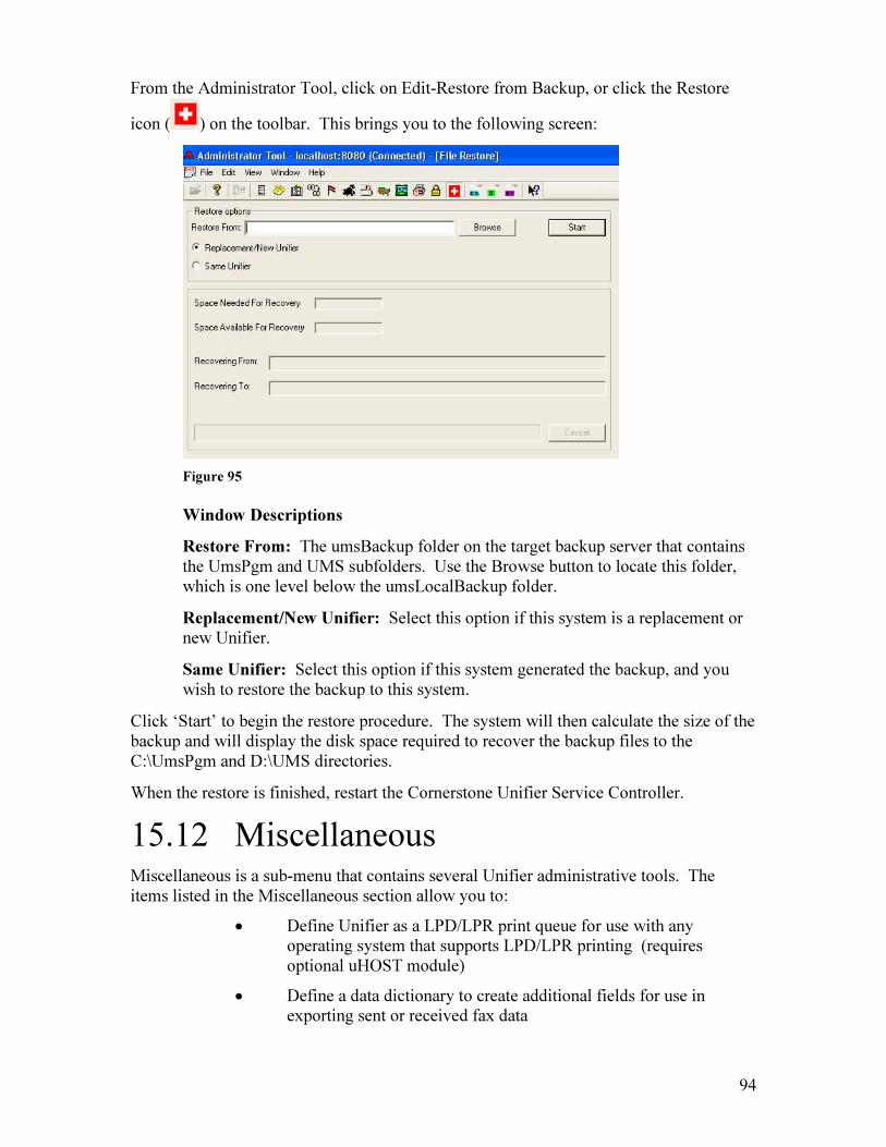
94
From the Administrator Tool, click on Edit-Restore from Backup, or click the Restore
icon ( ) on the toolbar. This brings you to the following screen:
Figure 95
Window Descriptions
Restore From: The umsBackup folder on the target backup server that contains the UmsPgm and UMS subfolders. Use the Browse button to locate this folder, which is one level below the umsLocalBackup folder.
Replacement/New Unifier: Select this option if this system is a replacement or new Unifier.
Same Unifier: Select this option if this system generated the backup, and you wish to restore the backup to this system.
Click ‘Start’ to begin the restore procedure. The system will then calculate the size of the backup and will display the disk space required to recover the backup files to the C:\UmsPgm and D:\UMS directories.
When the restore is finished, restart the Cornerstone Unifier Service Controller.
15.12 Miscellaneous Miscellaneous is a sub-menu that contains several Unifier administrative tools. The items listed in the Miscellaneous section allow you to:
• Define Unifier as a LPD/LPR print queue for use with any operating system that supports LPD/LPR printing (requires optional uHOST module)
• Define a data dictionary to create additional fields for use in exporting sent or received fax data
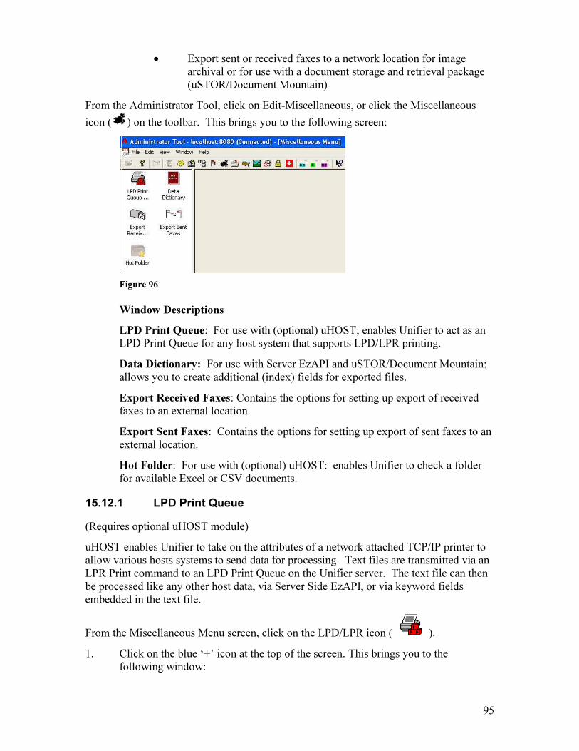
95
• Export sent or received faxes to a network location for image archival or for use with a document storage and retrieval package (uSTOR/Document Mountain)
From the Administrator Tool, click on Edit-Miscellaneous, or click the Miscellaneous
icon ( ) on the toolbar. This brings you to the following screen:
Figure 96
Window Descriptions
LPD Print Queue: For use with (optional) uHOST; enables Unifier to act as an LPD Print Queue for any host system that supports LPD/LPR printing.
Data Dictionary: For use with Server EzAPI and uSTOR/Document Mountain; allows you to create additional (index) fields for exported files.
Export Received Faxes: Contains the options for setting up export of received faxes to an external location.
Export Sent Faxes: Contains the options for setting up export of sent faxes to an external location.
Hot Folder: For use with (optional) uHOST: enables Unifier to check a folder for available Excel or CSV documents.
15.12.1 LPD Print Queue
(Requires optional uHOST module)
uHOST enables Unifier to take on the attributes of a network attached TCP/IP printer to allow various hosts systems to send data for processing. Text files are transmitted via an LPR Print command to an LPD Print Queue on the Unifier server. The text file can then be processed like any other host data, via Server Side EzAPI, or via keyword fields embedded in the text file.
From the Miscellaneous Menu screen, click on the LPD/LPR icon ( ).
1. Click on the blue ‘+’ icon at the top of the screen. This brings you to the following window:
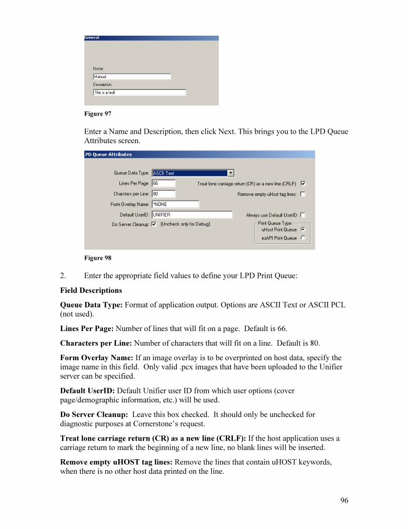
96
Figure 97
Enter a Name and Description, then click Next. This brings you to the LPD Queue Attributes screen.
Figure 98
2. Enter the appropriate field values to define your LPD Print Queue:
Field Descriptions
Queue Data Type: Format of application output. Options are ASCII Text or ASCII PCL (not used).
Lines Per Page: Number of lines that will fit on a page. Default is 66.
Characters per Line: Number of characters that will fit on a line. Default is 80.
Form Overlay Name: If an image overlay is to be overprinted on host data, specify the image name in this field. Only valid .pcx images that have been uploaded to the Unifier server can be specified.
Default UserID: Default Unifier user ID from which user options (cover page/demographic information, etc.) will be used.
Do Server Cleanup: Leave this box checked. It should only be unchecked for diagnostic purposes at Cornerstone’s request.
Treat lone carriage return (CR) as a new line (CRLF): If the host application uses a carriage return to mark the beginning of a new line, no blank lines will be inserted.
Remove empty uHOST tag lines: Remove the lines that contain uHOST keywords, when there is no other host data printed on the line.

97
Always use Default UserID: Regardless of what user sends the file, always use the Default Unifier UserID as noted above.
Print Queue Type: Options are uHOST Print Queue or EzAPI Print Queue. EzAPI Print Queue, when checked, will send the data on to Server Side EzAPI definitions for additional processing.
After defining the LPD Print Queue, you will need to embed keyword values in your document. These keywords will determine destination values such as contact, fax number, email address, etc.
A list of supported keyword is as follows:
#~ToCompany=Cornerstone Communications~#
#~ToPerson=John User~#
#~FromUserID=JUSER~#
#~Secondary=555-1212~#
#~ccSecondary=555-1313~#
#~ccToCompany=Lowe’s Home Improvement~#
#~ccToPerson=Accounting Dept~#
#~HardCopy=Y~#
#~SkipToFormFeed=Y~#
#~TabStop=5~#
#~Subject=Invoice for May shipment~#
#~Dictionary=DataDictionary1~#
15.12.2 Data Dictionary
Data Dictionaries contain a collection of additional field names for use when exporting Sent or Received faxes for archival purposes, or for use as index fields with (optional) uSTOR/Document Mountain.
From the Miscellaneous Menu screen, click on the Data Dictionary ( ) icon.
1. Click on the blue ‘+’ key on the toolbar. Enter the Data Dictionary name and a description, then click Next.
2. Click Add Entry to add a field name. When you are done adding field names, click OK.
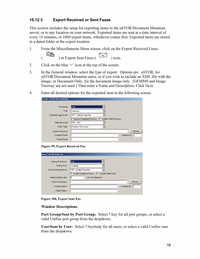
98
15.12.3 Export Received or Sent Faxes
This section includes the setup for exporting items to the uSTOR/Document Mountain server, or to any location on your network. Exported items are sent at a time interval of every 15 minutes, or 1000 export items, whichever comes first. Exported items are stored in a dated folder at the export location.
1. From the Miscellaneous Menu screen, click on the Export Received Faxes
( ) or Export Sent Faxes ( ) icon.
2. Click on the blue ‘+’ icon at the top of the screen.
3. In the General window, select the type of export. Options are: uSTOR, for uSTOR/Document Mountain users, or if you wish to include an XML file with the image; or Document Only, for the document image only. (GEMMS and Image Freeway are not used.) Then enter a Name and Description. Click Next.
4. Enter all desired options for the exported item in the following screen.
Figure 99, Export Received Fax
Figure 100, Export Sent Fax
Window Descriptions
Port Group/Sent by Port Group: Select *Any for all port groups, or select a valid Unifier port group from the dropdown.
User/Sent by User: Select *Anybody for all users, or select a valid Unifier user from the dropdown.

99
Exported Image format: The format that the exported item will be stored as. The format will depend on the storage/retrieval software you are using. Valid formats are PDF, Windows BMP (not recommended due to size), Intel DCX, TIFF Multiple Page files, TIFF Single Page files, CStone iscs files (searchable image), and Windows File System. For uSTOR/Document Mountain users, this
should be TIFF Single Page.
Include Completed Receives/Sends: Check if you want completed receives/sends to be included.
Include Failed Receives/Sends: Check if you want failed receives/sends to be included. Any successfully sent or received portion of a failed fax will be exported.
Maximum Batch Size (Sent Faxes only): The maximum number of items in a batch that will be exported. This is provided so that broadcast faxes may be excluded.
Data File Format (Received Faxes only): The saved format of the exported data file. The data file is used by the receiving application to describe the exported images. Valid formats are XML or TXT. For uSTOR/Document Mountain users, this should be XML, and the actual data items will correspond with Index Values
on the uSTOR/Document Mountain server.
Export Type (Received Faxes only): Windows File System is the default and the only option at this time.
Export to Directory: Must be a fully qualified UNC name (\\ServerName\Share\Directory or \\ServerName\Share\Filename). For uSTOR/Document Mountain users, this should be the path to the
uSTOR/Document Mountain server.
Company Name: Enter your company name. For uSTOR/Document Mountain
users, this must match the Entity name on the uSTOR/Document Mountain server.
Company ID: Enter a company ID. For uSTOR/Document Mountain users, this must match the Entity ID on the uSTOR/Document Mountain server.
Project Name: Enter a Project Name. For uSTOR/Document Mountain users, this
must match the Project Name on the uSTOR/Document Mountain server.
5. Click Next. This brings you to the Attributes window. This is where you map
Unifier data elements to the recipient application data elements. 6. Click Add Field on the right side of the window. 7. Choose a Unifier Data Type from the dropdown.
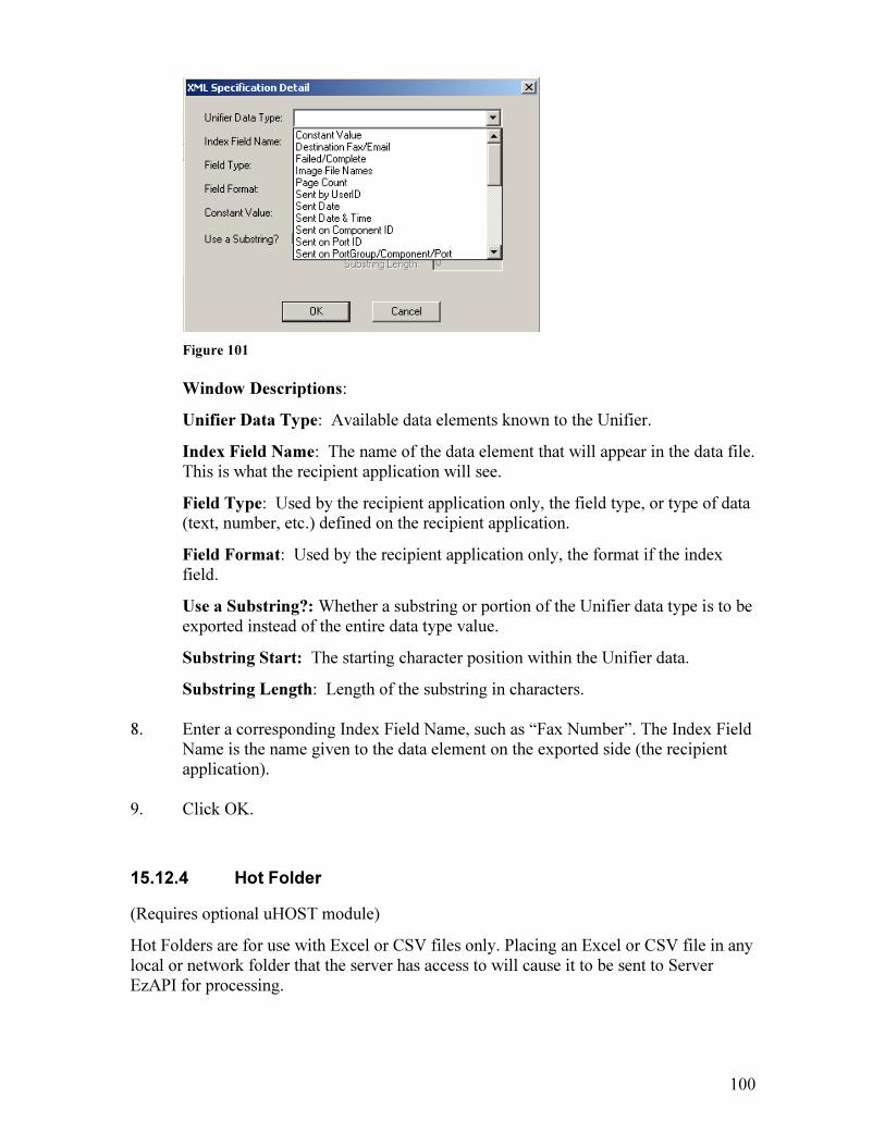
100
Figure 101
Window Descriptions:
Unifier Data Type: Available data elements known to the Unifier.
Index Field Name: The name of the data element that will appear in the data file. This is what the recipient application will see.
Field Type: Used by the recipient application only, the field type, or type of data (text, number, etc.) defined on the recipient application.
Field Format: Used by the recipient application only, the format if the index field.
Use a Substring?: Whether a substring or portion of the Unifier data type is to be exported instead of the entire data type value.
Substring Start: The starting character position within the Unifier data.
Substring Length: Length of the substring in characters. 8. Enter a corresponding Index Field Name, such as “Fax Number”. The Index Field
Name is the name given to the data element on the exported side (the recipient application).
9. Click OK.
15.12.4 Hot Folder
(Requires optional uHOST module)
Hot Folders are for use with Excel or CSV files only. Placing an Excel or CSV file in any local or network folder that the server has access to will cause it to be sent to Server EzAPI for processing.

101
1. From the Miscellaneous Menu, select the Hot Folder icon ( ).
2. Click on the blue ‘+’ icon at the top of the screen.
3. Enter a Name and Description for the Hot Folder, then select ‘Next’. This will bring you to the Processing tab.
Figure 102
Window Descriptions:
Folder Path: The folder path for the Hot Folder. Select ‘Include Subfolders’ if you want to include subfolders in this location.
File Filter: Enter the extension of the file you are using, if the folder is to contain multiple types of files.
EzAPI Definition: The name of the EzAPI definition that will be processing the Hot Folder documents. Note that you will need to create the Server EzAPI definition before it shows up in the dropdown.
Default User: Select a valid Unifier user from the dropdown.
Post Processing:
Delete: Check if you want the file to be deleted after it is processed by Server EzAPI.
Move: Check if you want the file to be moved after it is processed by Server EzAPI, and select a location. Check ‘User Date Subfolders’ if you would like to have dated subfolders created at the target location.
Rename: Check if you want the file to be renamed after it is processed by Server EzAPI, and include a filename.
Then select ‘Next’.

102
4. Select ‘Next’. This will bring you to the Scheduling tab.
Figure 103
Window Descriptions:
Every x Minutes: Enter the interval, in minutes,that you would like the Hot Folder to be checked for available documents.
Scheduled Event: Select a Daily, Weekly, or Monthly interval.
5. Select ‘Finish’.
15.13 Shared Address Books Shared address books are a listing of contacts stored on a public location on your network (not on the Unifier server) which are available to all Unifier users, via Policy Rights in the User Profile Tool.
Creating a Shared Address Book
1. Select the New Address Book Icon.
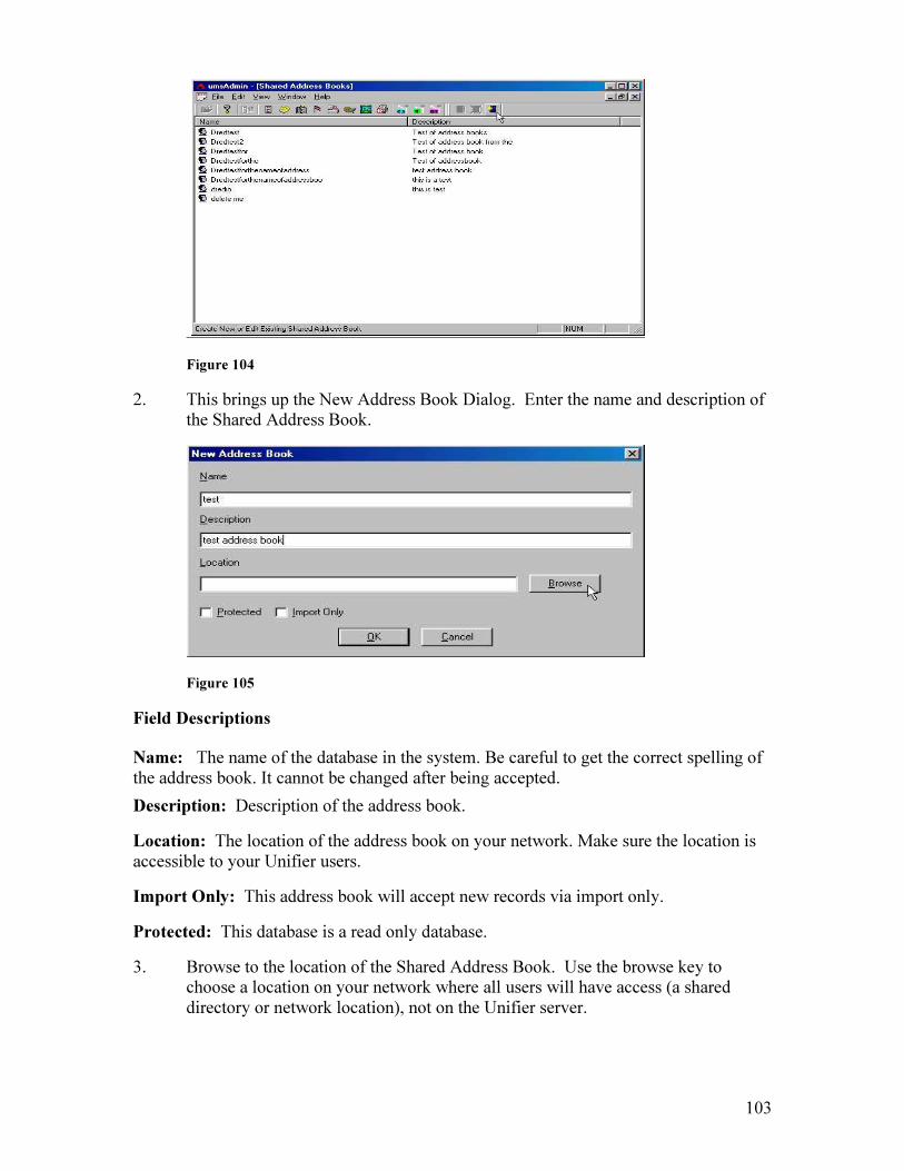
103
Figure 104
2. This brings up the New Address Book Dialog. Enter the name and description of the Shared Address Book.
Figure 105
Field Descriptions
Name: The name of the database in the system. Be careful to get the correct spelling of the address book. It cannot be changed after being accepted.
Description: Description of the address book.
Location: The location of the address book on your network. Make sure the location is accessible to your Unifier users.
Import Only: This address book will accept new records via import only.
Protected: This database is a read only database.
3. Browse to the location of the Shared Address Book. Use the browse key to choose a location on your network where all users will have access (a shared directory or network location), not on the Unifier server.
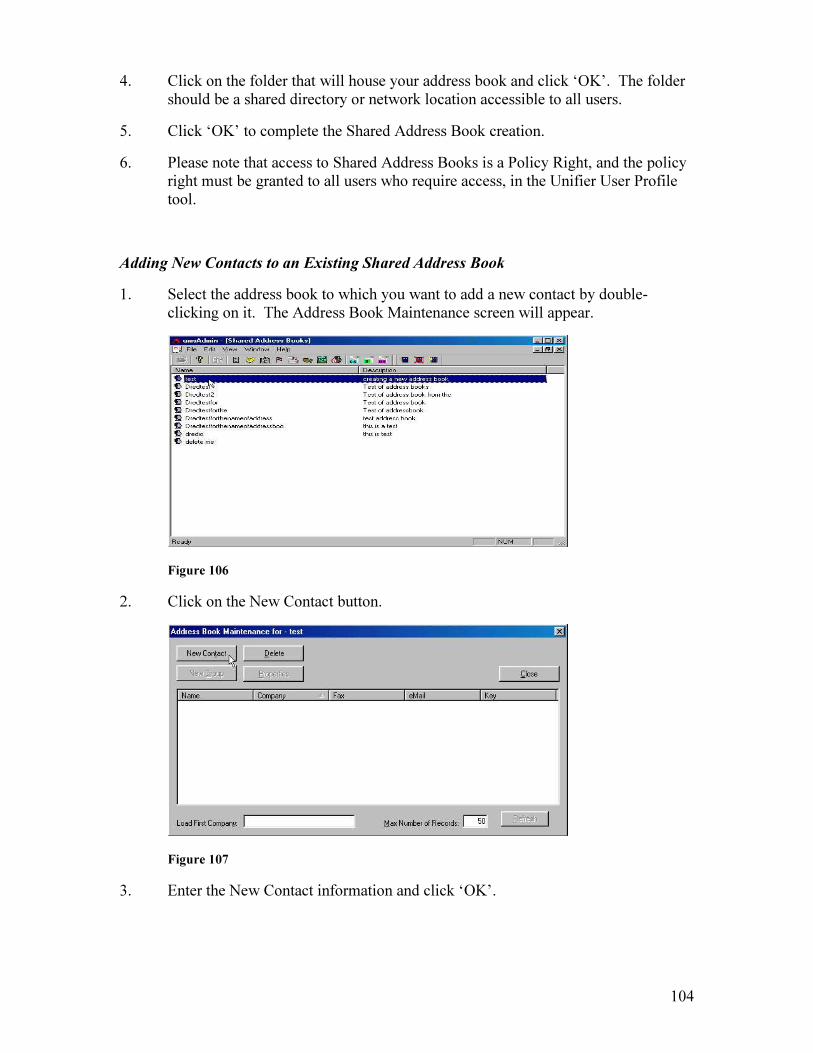
104
4. Click on the folder that will house your address book and click ‘OK’. The folder should be a shared directory or network location accessible to all users.
5. Click ‘OK’ to complete the Shared Address Book creation.
6. Please note that access to Shared Address Books is a Policy Right, and the policy right must be granted to all users who require access, in the Unifier User Profile tool.
Adding New Contacts to an Existing Shared Address Book
1. Select the address book to which you want to add a new contact by double-clicking on it. The Address Book Maintenance screen will appear.
Figure 106
2. Click on the New Contact button.
Figure 107
3. Enter the New Contact information and click ‘OK’.

105
Figure 108
Deleting a Shared Address Book
1. Select an address book and click the Delete Address Book icon.
Figure 109
2. A dialog box will appear that will confirm that the address book is to be deleted. Click ‘OK’.
Creating Groups
A message may be sent to a pre-defined list of destinations (contacts) by using Groups. A Group contains a list of contacts from a Shared Address Book.
1. Select the Shared Address Book whose members will comprise the Group by double-clicking on it in the Shared Address Book window.
2. Click the New Group button. The Group Properties window will appear with the members of the Shared Address Book listed in the Contacts window.

106
Figure 110
3. Enter the Group Name.
4. Add members to the Group by selecting (clicking on) a contact and clicking the ‘<’ button. To remove a contact from the group, select (click on) a member and click on the ‘>’ button.
5. Click ‘OK’.
15.14 System Defaults
System Information: Company name and component ID’s for this machine.
Email/SMTP Information: Your SMTP server’s IP address and email sending defaults, and SMTP Authentication username and password.
Fax Sending Defaults: Fax Service and Port Group faxes will be send over and sending defaults.
Print Information: Retry values and delay for printed faxes.
Fax Service Information: Bundling and DTMF routing options.
Database Cleanup: Clears Unifier of log entries and batches.
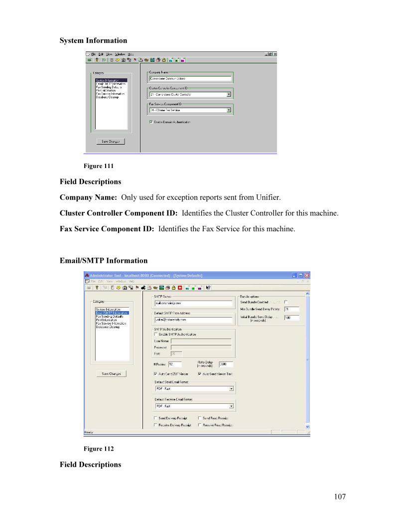
107
System Information
Figure 111
Field Descriptions
Company Name: Only used for exception reports sent from Unifier.
Cluster Controller Component ID: Identifies the Cluster Controller for this machine.
Fax Service Component ID: Identifies the Fax Service for this machine.
Email/SMTP Information
Figure 112
Field Descriptions
108
SMTP Server: The IP address of the mail server that sends your email messages. Please note that relay capabilities are required for Unifier on your SMTP server.
Default SMTP From Address: The return address referenced on emails sent from the Unifier when a from address is not available (for example, a user who does not have a Unifier User Profile enabled sends a fax via email from the AS400). This field is required.
Send Email Bundle Enabled: Enables the email bundling feature. Bundling enables more than one email with the same destination to be sent in one batch, as separate attachments. The body of the bundled email will contain information about each attachment.
Min Bundle Send Delay Priority: The minimum priority of batches to which bundling will be applied. The default priority is 21.
Initial Bundle Send Delay: The number of seconds a batch is held before bundling. The default is 180 seconds (3 minutes).
Enable SMTP Authentication: Check only if Login Authentication is required by your SMTP server. Enter a User Name and Password for Login Authentication.
# Retries: The number of times an email will be retried. The default is 12.
Retry Delay: The number of seconds before attempting to resend an email that has attempts remaining. When a destination fails but has remaining retries, the destination will be emailed at a later time. Valid values are 1 second to 32,767 seconds. A change to this parameter will take affect the next time the Unifier is rebooted.
Auto Send ZUF Viewer: The viewer enables the recipient to view a fax sent via email in ZUF (Cornerstone proprietary) format, and is sent only one time to each recipient as an attachment. Not necessary if you are sending emails in TIF or PDF format.
Auto Send ZUF Web Link: Sends the recipient the web link in order to download the ZUF (Cornerstone proprietary) viewer. Not necessary if you are sending emails in TIF or PDF format.
Default Send Email Format: Options are ZUF (Cornerstone proprietary), TIF (Tagged Image Format), PDF-Slow (accommodates older versions of Adobe Acrobat), and PDF-Fast. If PDF is selected, a link to the latest version of Adobe Acrobat is included in the text of the email.
Note: Whatever format you choose for Default Send Email Format, the format can be selected at the time of sending. Specify the desired format in the email address by typing a colon, then the desired format after the address ([email protected]:ZUF).
Default Receive Email Format: Specify the format for received/routed emails. Options are ZUF, TIF, PDF.
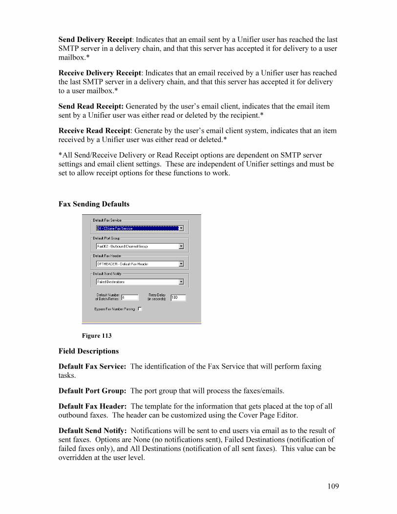
109
Send Delivery Receipt: Indicates that an email sent by a Unifier user has reached the last SMTP server in a delivery chain, and that this server has accepted it for delivery to a user mailbox.*
Receive Delivery Receipt: Indicates that an email received by a Unifier user has reached the last SMTP server in a delivery chain, and that this server has accepted it for delivery to a user mailbox.*
Send Read Receipt: Generated by the user’s email client, indicates that the email item sent by a Unifier user was either read or deleted by the recipient.*
Receive Read Receipt: Generate by the user’s email client system, indicates that an item received by a Unifier user was either read or deleted.*
*All Send/Receive Delivery or Read Receipt options are dependent on SMTP server settings and email client settings. These are independent of Unifier settings and must be set to allow receipt options for these functions to work.
Fax Sending Defaults
Figure 113
Field Descriptions
Default Fax Service: The identification of the Fax Service that will perform faxing tasks.
Default Port Group: The port group that will process the faxes/emails.
Default Fax Header: The template for the information that gets placed at the top of all outbound faxes. The header can be customized using the Cover Page Editor.
Default Send Notify: Notifications will be sent to end users via email as to the result of sent faxes. Options are None (no notifications sent), Failed Destinations (notification of failed faxes only), and All Destinations (notification of all sent faxes). This value can be overridden at the user level.

110
Default Number of Batch Retries: The number of times an incomplete destination will be sent, including the initial try.
Retry Delay: The number of seconds before attempting to resend a fax that has attempts remaining. When a destination fails but has remaining retries, the fax will be sent at a later time. Valid values are 1 second to 32,767 seconds. The shipped default is 180 seconds or 3 minutes. A change to this parameter will take affect the next time the Unifier is rebooted.
Bypass Fax Number Parsing: Used for international locations, or when the exact number entered by the user is what should be dialed (Unifier will not add a one to ANY fax number, and will dial the exact digits entered by the user). Do not check this box unless it is recommended for your environment.
Print Information
Figure 114
Field Descriptions
Max Print Retries: The number of times, including the initial try, a print job (successful fax or received fax) will attempt to print.
Retry Delay: The number of seconds the system will wait before attempting to reprint. When a print fails but has remaining retries, the print will be rescheduled at a later time. Valid values are 1 second to 32,767 seconds. The shipped default is 1800 seconds or 30 minutes. A change to this parameter will take affect the next time the Unifier is rebooted.

111
Fax Service Information
Figure 115
Field Descriptions
Send Bundle Enable: Enables the bundling feature. The default is on. Bundling enables more than one fax with the same destination to be sent in one batch.
Min Bundle Send Delay Priority: The minimum priority of batches to which bundling will be applied. The default priority is 21.
Initial Bundle Send Delay: The number of seconds a batch is held before bundling. The default is 300 seconds (5 minutes).
Enable DTMF Routing: Enables the DTMF feature. The default is on.
Wait for DTMF Info: The number of seconds to wait for DTMF information.
DTMF Settle After Answer Time: The amount of time (in milliseconds) that Unifier will wait before listening for DTMF tones from the sending fax machine.
Play Greeting: Whether or not Unifier will play audible tones to alert the sender to enter DTMF information.
Number of DID Digits: The number of DID digits expected by Unifier. Unifier can accept from 1-9 digits.
Require All DID Digits: If checked, Unifier will listen for number of DID digits specified in Number of DID Digits field. If 7 digits are expected, and only 4 are dialed, the call is not completed. This box should be checked if you are using DID.
Database Cleanup
The Database Cleanup option clears the Unifier of log entries and incomplete and complete batches, both sent and received. Database Cleanup is run during system startup, or after Unifier Scheduled Backup.
If the ‘Start Database Cleanup’ button is pressed, the Unifier will start a Database Cleanup immediately. It will continue to send and receive faxes, but will not email.
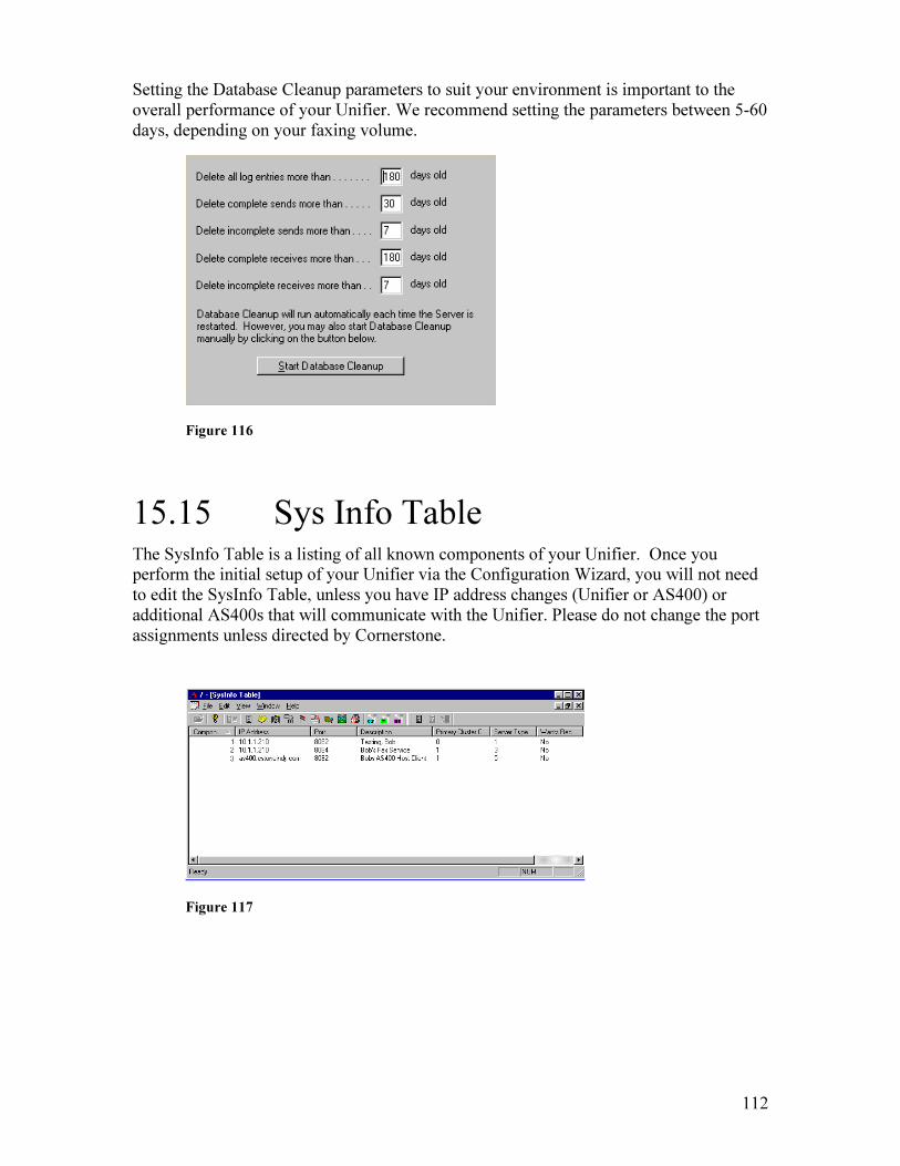
112
Setting the Database Cleanup parameters to suit your environment is important to the overall performance of your Unifier. We recommend setting the parameters between 5-60 days, depending on your faxing volume.
Figure 116
15.15 Sys Info Table The SysInfo Table is a listing of all known components of your Unifier. Once you perform the initial setup of your Unifier via the Configuration Wizard, you will not need to edit the SysInfo Table, unless you have IP address changes (Unifier or AS400) or additional AS400s that will communicate with the Unifier. Please do not change the port assignments unless directed by Cornerstone.
Figure 117
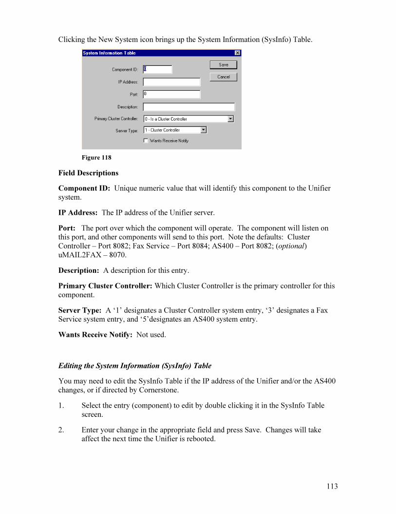
113
Clicking the New System icon brings up the System Information (SysInfo) Table.
Figure 118
Field Descriptions
Component ID: Unique numeric value that will identify this component to the Unifier system.
IP Address: The IP address of the Unifier server.
Port: The port over which the component will operate. The component will listen on this port, and other components will send to this port. Note the defaults: Cluster Controller – Port 8082; Fax Service – Port 8084; AS400 – Port 8082; (optional) uMAIL2FAX – 8070.
Description: A description for this entry.
Primary Cluster Controller: Which Cluster Controller is the primary controller for this component.
Server Type: A ‘1’ designates a Cluster Controller system entry, ‘3’ designates a Fax Service system entry, and ‘5’designates an AS400 system entry.
Wants Receive Notify: Not used.
Editing the System Information (SysInfo) Table
You may need to edit the SysInfo Table if the IP address of the Unifier and/or the AS400 changes, or if directed by Cornerstone.
1. Select the entry (component) to edit by double clicking it in the SysInfo Table screen.
2. Enter your change in the appropriate field and press Save. Changes will take affect the next time the Unifier is rebooted.
114
16. Image Utility The Image Utility programs allow users to transfer images between the Unifier and a PC or from an AS400 to the Unifier, convert PCX format images to DCX format (and vice-versa), and to convert received faxes into usable PCX images.
Click on the Image Utility icon on the Unifier desktop. The individual programs may then be selected from the icon toolbar (Image Utilities are installed on a workstation when a custom install is done).
To access images on your AS400, click View, then Options, and enter the IP address of your AS400. Click on the Download Image icon, enter your AS400 logon, and you will see a listing of images on the AS400.
You will then see the Image Utilities Window.
Figure 119
Toolbar Options:
Dcx>Pcx: Split a DCX file into PCX files.
Pcx>Dcx: Merge PCX files into a DCX file.
UploadImg: Transfer an image from your PC or diskette to the Unifier.
DownloadImg: Transfer an image from the Unifier to your PC or diskette.
Fax2Img: Convert a fax into a usable PCX image for the Unifier.
SavePcx: Save the image in PCX file format.
OverLay: Edit an image overlay.

115
ViewImage: Select and view images.
Unifier Images
There are two types of image formats that can be used with Unifier: PCX and DCX.
A PCX image is one page or part of a page. A PCX image can be merged with text, but may not be faxed by itself. Examples of PCX images include purchase order forms, invoice overlays, logos, letterhead images, signatures, and cover page letterhead images. PCX images must be scanned at 200 dpi and uploaded to the Unifier to be used as an overlay.
A DCX image may be one or more pages in length. A DCX image must be faxed by itself; it cannot be merged with text. Examples of DCX images include scanned brochures and documents created by Windows applications. DCX images reside on the AS400, not on the Unifier server, and can only be sent from the Work with Images screen on the AS400. DCX images can be created by clicking the “Capture Only” box on the Assign Destinations to Fax screen.
The size limit for PCX images is 1727 x 2200 pixels, with a color depth of 2 (black and white). Unifier assumes the image is 200 dpi and will calculate the image size based on this.
16.1 DCX to PCX A DCX file contains one or more pages that have been scanned or saved in the DCX format, such as brochures, Windows documents, etc. This option creates an individual PCX image file for each page of the DCX file. The original file must be on your PC before running this conversion, and the new files will also be placed on your PC.
Clicking on the DCX to PCX icon, , causes the following window to appear.
Figure 120
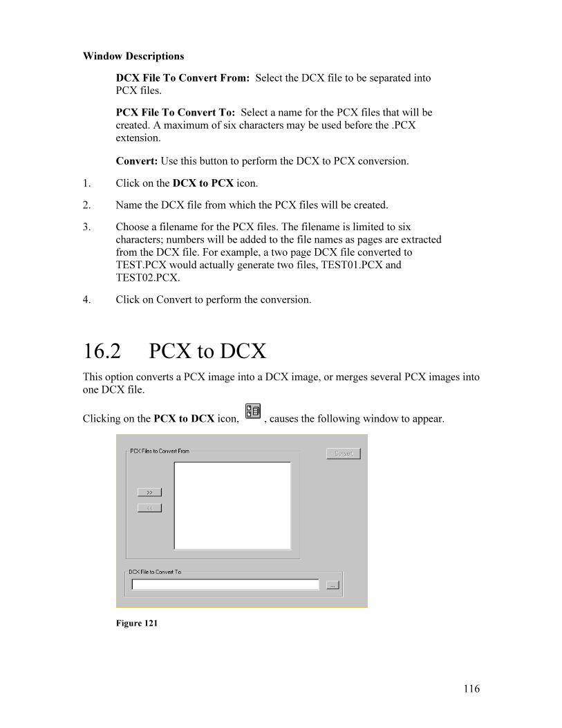
116
Window Descriptions
DCX File To Convert From: Select the DCX file to be separated into PCX files.
PCX File To Convert To: Select a name for the PCX files that will be created. A maximum of six characters may be used before the .PCX extension.
Convert: Use this button to perform the DCX to PCX conversion.
1. Click on the DCX to PCX icon.
2. Name the DCX file from which the PCX files will be created.
3. Choose a filename for the PCX files. The filename is limited to six characters; numbers will be added to the file names as pages are extracted from the DCX file. For example, a two page DCX file converted to TEST.PCX would actually generate two files, TEST01.PCX and TEST02.PCX.
4. Click on Convert to perform the conversion.
16.2 PCX to DCX This option converts a PCX image into a DCX image, or merges several PCX images into one DCX file.
Clicking on the PCX to DCX icon, , causes the following window to appear.
Figure 121
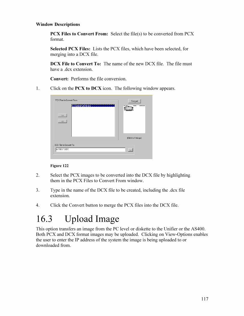
117
Window Descriptions
PCX Files to Convert From: Select the file(s) to be converted from PCX format.
Selected PCX Files: Lists the PCX files, which have been selected, for merging into a DCX file.
DCX File to Convert To: The name of the new DCX file. The file must have a .dcx extension.
Convert: Performs the file conversion.
1. Click on the PCX to DCX icon. The following window appears.
Figure 122
2. Select the PCX images to be converted into the DCX file by highlighting them in the PCX Files to Convert From window.
3. Type in the name of the DCX file to be created, including the .dcx file extension.
4. Click the Convert button to merge the PCX files into the DCX file.
16.3 Upload Image This option transfers an image from the PC level or diskette to the Unifier or the AS400. Both PCX and DCX format images may be uploaded. Clicking on View-Options enables the user to enter the IP address of the system the image is being uploaded to or downloaded from.

118
1. Clicking on the Upload Image to Host icon ( ) causes an “Open” window to appear. You must now locate and open the Unifier1.cfx file (if you are accessing the Image Utility from your PC), or the localhost.cfx file (if you are accessing the Image Utility from the Unifier server desktop). This is the configuration file.
After you have located and opened the *.cfx file, the following window will appear:
Figure 123
Window Descriptions
Image to Upload: The image to be uploaded.
Image Description on Host: A description of the image.
Image Name on Host: The image name as it will be stored on the Unifier or AS400.
Image Authority: Anyone can use Public images; only the owner of the image can use Private images; and only users enrolled in a selected department can use Department images.
Image Owner: The owner of the image.
Current Host Images: A list of current images on the Unifier.
2. Browse to the image to be uploaded in the “Image to Upload” field.
3. Fill in the Image Name on Host field with the name you want the image to be stored as on the Unifier.
4. Fill in the Description box with a description of the image being uploaded.
5. Choose the Image Authority.

119
6. Click the Upload button to complete the transfer of the image to the Unifier. After the transfer is complete, the image will be listed in the Current Host Images window.
16.4 Download Image This option transfers a Unifier image from the Unifier to a PC or network location. Both PCX and DCX format images may be transferred.
1. Clicking on the Download Image From Host icon ( ) causes an “Open” window to appear. You must now locate and open the Unifier1.cfx file (if you are accessing the Image Utility from your PC), or the localhost.cfx file (if you are accessing the Image Utility from the Unifier server desktop). This is the configuration file.
After you have located and opened the *.cfx file, the following window will appear:
Figure 124
Window Descriptions
Current Host Images: A list of images currently on the Unifier.
Download Image To: The location where you would like to download the Unifier image.
2. Highlight the image to be downloaded from the Current Host Images list.
3. Browse to the location for the downloaded image in the “Download Image to” field.

120
4. Click on the Download from Host button to complete the transfer.
16.5 Fax to Image The Fax-to-Image utility converts a fax that has been received by the Unifier into an image that can be used as an overlay.
Choosing the Fax-to-Image icon, , causes the following window to appear.
Figure 125
Select No if the image is to be downloaded from a local drive.
Select yes if the image to be downloaded is located on the Unifier. The following window will appear:
Figure 126
Window Descriptions
Received Faxes: A list of faxes that the Unifier has received. The date and time the fax was received, as well as the Sender ID from the sending fax, will be displayed.
Host Image Name: Fill in this box with the desired name for the converted image.
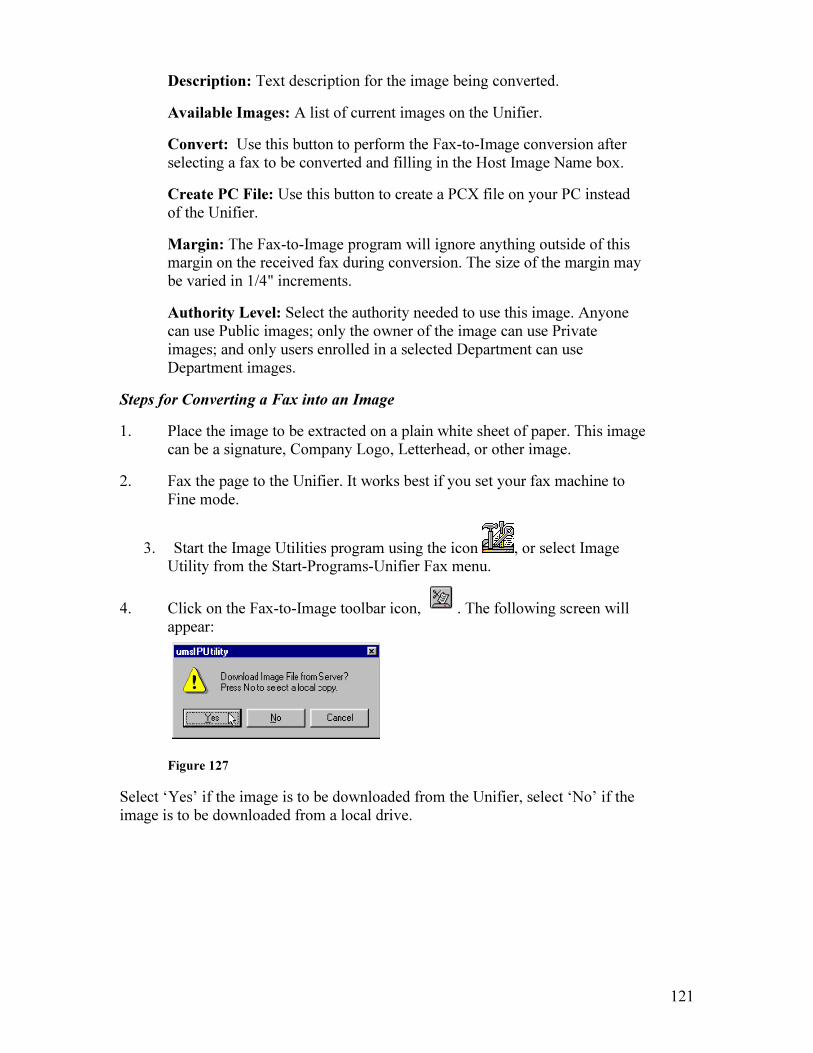
121
Description: Text description for the image being converted.
Available Images: A list of current images on the Unifier.
Convert: Use this button to perform the Fax-to-Image conversion after selecting a fax to be converted and filling in the Host Image Name box.
Create PC File: Use this button to create a PCX file on your PC instead of the Unifier.
Margin: The Fax-to-Image program will ignore anything outside of this margin on the received fax during conversion. The size of the margin may be varied in 1/4" increments.
Authority Level: Select the authority needed to use this image. Anyone can use Public images; only the owner of the image can use Private images; and only users enrolled in a selected Department can use Department images.
Steps for Converting a Fax into an Image
1. Place the image to be extracted on a plain white sheet of paper. This image can be a signature, Company Logo, Letterhead, or other image.
2. Fax the page to the Unifier. It works best if you set your fax machine to Fine mode.
3. Start the Image Utilities program using the icon , or select Image Utility from the Start-Programs-Unifier Fax menu.
4. Click on the Fax-to-Image toolbar icon, . The following screen will appear:
Figure 127
Select ‘Yes’ if the image is to be downloaded from the Unifier, select ‘No’ if the image is to be downloaded from a local drive.

122
Figure 128
If no faxes are listed in the Current Host Images screen, you may need to change the directory where the images are located. By default, all received and routed faxes go to the folder Unifier. To change search location, first choose menu option View. Next, choose Image. Finally, choose a new image from the View Image list.
5. Highlight the image to be converted in the Current Host Images window.
6. Fill in the Download Image To box with the desired location and name of the image. If the Fax to be converted is doubled clicked during selection, this field is updated to the user’s Temp directory with the file name being the current image name. The image will be converted automatically.
7. Click on the Download Image from Host button to convert the received fax to an image. The image will be stored in the Download Image to location.
16.6 Save PCX This option allows a DCX image to be saved in a PCX format.

123
Figure 129
1. Click on the Fax to Image icon.
2. Select the DCX image to be saved by double clicking on it. When the image is opened, click on the Save PCX icon. The following window will appear:
Figure 130
3. Click the drop down arrow of the ‘Save in’ section to select the drive and directory where the image is to be located if is not on the default drive or directory.
4. Type in the image file name if the default name is not acceptable and click the Save button.
5. When the image has been saved, the ‘Upload File Now?’ box will appear with an option to upload the image for system use.
124
Figure 131
Selecting ‘No’ would complete the Save as PCX processing.
Selecting ‘Yes’ would upload the image to the Unifier system.
16.7 OverLay This option allows an overlay to be edited for alignment with spoolfile data utilizing a grid that is generated on the AS400. You will need: an original blank overlay form with spool data printed on it in correct positions; a blank original overlay form scanned into your PC at no greater than 1727x2200 pixels with a color depth of 2 in .pcx format; some imaging software for editing, and the Unifier Image Utilities application.
1. In the fax menu on the AS400, type XFSNDGRID and F4 to prompt. Enter the column and row size of the spoolfile you will be using with the overlay you are sizing. Enter your fax number or email address in the TOFAXPHONE field. Press Enter.
2. Open Fax Center and open the received fax (the grid) you created in step 1. You will now see the grid in the lower portion of your screen.
3. Right click on the body of the grid. Click on ‘Save Page As’, and save the grid as a .pcx image on your PC. Exit Fax Center.
4. Open the Unifier Image Utilities application and select the OverLay icon ( ).
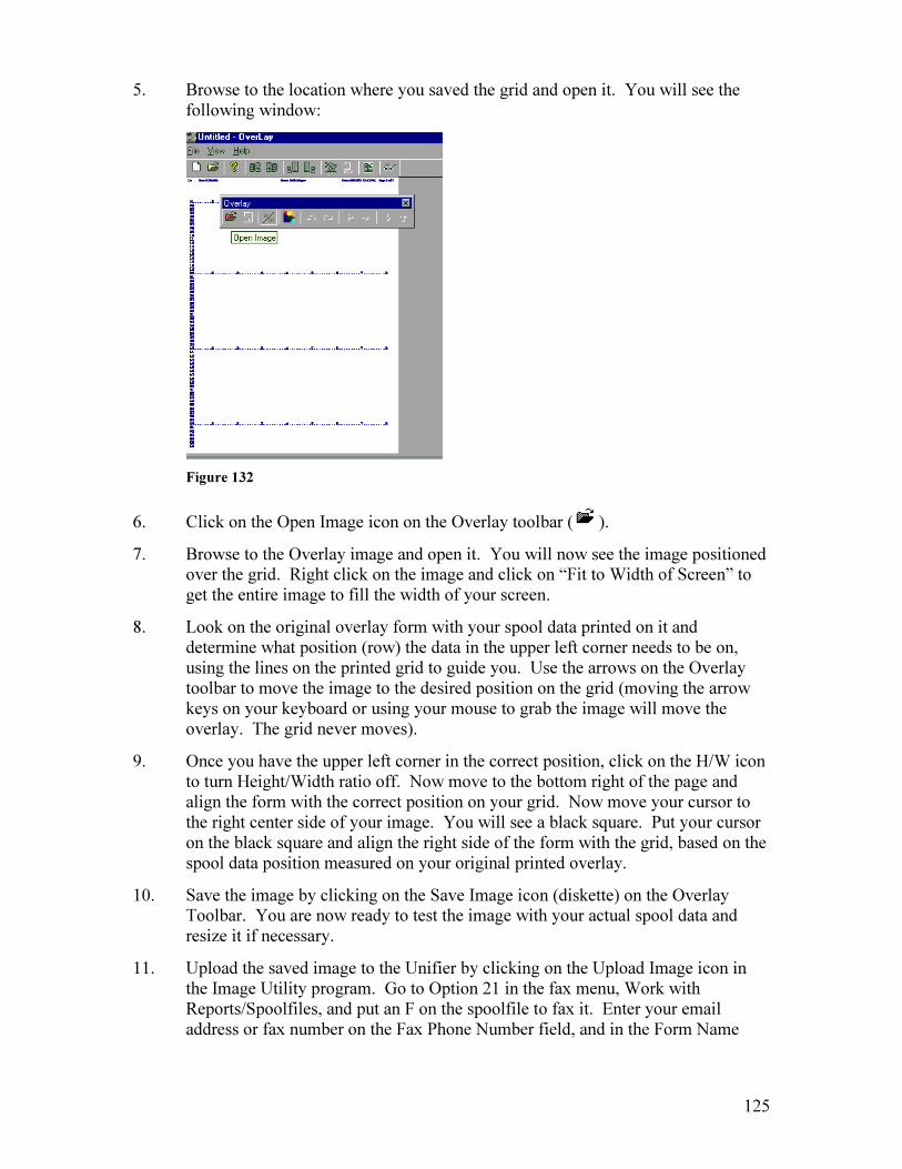
125
5. Browse to the location where you saved the grid and open it. You will see the following window:
Figure 132
6. Click on the Open Image icon on the Overlay toolbar ( ).
7. Browse to the Overlay image and open it. You will now see the image positioned over the grid. Right click on the image and click on “Fit to Width of Screen” to get the entire image to fill the width of your screen.
8. Look on the original overlay form with your spool data printed on it and determine what position (row) the data in the upper left corner needs to be on, using the lines on the printed grid to guide you. Use the arrows on the Overlay toolbar to move the image to the desired position on the grid (moving the arrow keys on your keyboard or using your mouse to grab the image will move the overlay. The grid never moves).
9. Once you have the upper left corner in the correct position, click on the H/W icon to turn Height/Width ratio off. Now move to the bottom right of the page and align the form with the correct position on your grid. Now move your cursor to the right center side of your image. You will see a black square. Put your cursor on the black square and align the right side of the form with the grid, based on the spool data position measured on your original printed overlay.
10. Save the image by clicking on the Save Image icon (diskette) on the Overlay Toolbar. You are now ready to test the image with your actual spool data and resize it if necessary.
11. Upload the saved image to the Unifier by clicking on the Upload Image icon in the Image Utility program. Go to Option 21 in the fax menu, Work with Reports/Spoolfiles, and put an F on the spoolfile to fax it. Enter your email address or fax number on the Fax Phone Number field, and in the Form Name
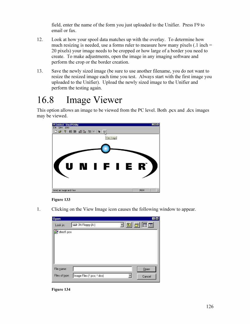
126
field, enter the name of the form you just uploaded to the Unifier. Press F9 to email or fax.
12. Look at how your spool data matches up with the overlay. To determine how much resizing is needed, use a forms ruler to measure how many pixels (.1 inch = 20 pixels) your image needs to be cropped or how large of a border you need to create. To make adjustments, open the image in any imaging software and perform the crop or the border creation.
13. Save the newly sized image (be sure to use another filename, you do not want to resize the resized image each time you test. Always start with the first image you uploaded to the Unifier). Upload the newly sized image to the Unifier and perform the testing again.
16.8 Image Viewer This option allows an image to be viewed from the PC level. Both .pcx and .dcx images may be viewed.
Figure 133
1. Clicking on the View Image icon causes the following window to appear.
Figure 134

127
2. Click the drop down arrow of the ‘Look in’ section to select the drive and directory where the image is located if is not on the default drive or directory.
3. Click on the image file name to select the image and click the Open button to confirm selection of the image to view.
4. When the loading of the image is complete, the Viewer will appear with a full representation of the image file.
5. Click anywhere within the Image View screen to disable the Viewer.

128
17. Unifier Monitor Unifier Monitor is a diagnostic tool that provides useful logging information, and it allows you to see what processes are taking place at any specific time. It also keeps track of all pending faxes/emails, number of licensed workstations, and known workstations. The Unifier Monitor does not need to be left running on your Unifier. Close the application unless you are actively monitoring fax activity, or checking your server connectivity.
To open the Unifier Monitor, click on the Unifier Monitor icon on the Unifier desktop. This brings up the following screen:
Figure 135
There are 3 components of Unifier:
Cluster Controller – This is the brains of the Unifier and is what communicates with the outside world, including all host type system and Windows clients. The Cluster Controller is also where outgoing messages are prepared, cover pages are generated, and all outbound fax routing and emailing takes place.
Fax Service – This is what handles sending, queuing and retrying of outgoing faxes, and reports final disposition of faxes to the appropriate Cluster Controller. Received faxes are received by the Fax Service and sent to the appropriate Cluster Controller for routing. The Fax Service is what communicates with the fax hardware and handles fax specific tasks.
Host System – AS400 system that sends large quantities of faxes to the Unifier.
Viewing the Cluster Controller side of the Monitor will allow you to see the progress of queued faxes, emails, and all other work being processed on Unifier. Information is reported from the Fax Service (the actual fax hardware) to the Cluster Controller, and is

129
logged in the ‘Message’ portion of the Unifier Monitor screen. The Cluster Controller side of the Monitor also tells you if an AS400 (Host) is connected.
Viewing the Cluster Controller side of the Monitor
1. Enter the IP address or Host Name of the Unifier, Port 8080, and click Connect. (After your first logon to the Monitor, an icon will be created in the ‘Unifier Fax Servers’ portion of the window. You will be able to click on the icon in subsequent logons to bring up the Unifier IP address.)
2. Confirm that Port 8080 is listed in the Port field, and click Connect. This brings you to the following screen:
Figure 136
3. The Fax and Host items on the left (under the Type heading) should always show a Connected status of ‘Yes’. To force a reconnect of the Host, end and restart the FAXTCPIP subsystem on the AS400. Please note that the Fax and Host may take several minutes to connect.
Field Definitions
Connections: The number of clients currently logged onto the Unifier.
Preparation Pending: The number of items currently being prepared for faxing or emailing, including status reports and internal communications between the Fax Service and Cluster Controller.
Print Pending: The number of print jobs currently queued for print.
Known Workstations: The number of client workstations the Unifier knows about, or have logged on.
Post Preparation Pending: The number of destinations being prepared for faxing or emailing.
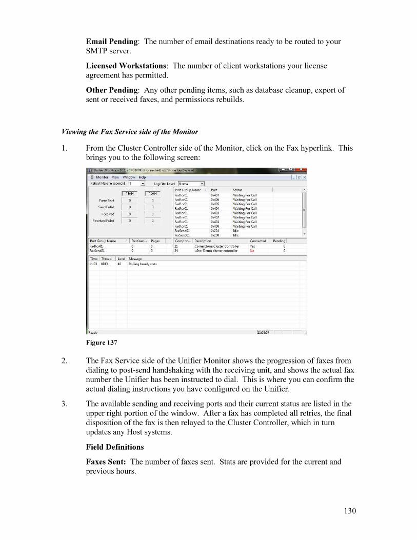
130
Email Pending: The number of email destinations ready to be routed to your SMTP server.
Licensed Workstations: The number of client workstations your license agreement has permitted.
Other Pending: Any other pending items, such as database cleanup, export of sent or received faxes, and permissions rebuilds.
Viewing the Fax Service side of the Monitor
1. From the Cluster Controller side of the Monitor, click on the Fax hyperlink. This brings you to the following screen:
Figure 137
2. The Fax Service side of the Unifier Monitor shows the progression of faxes from dialing to post-send handshaking with the receiving unit, and shows the actual fax number the Unifier has been instructed to dial. This is where you can confirm the actual dialing instructions you have configured on the Unifier.
3. The available sending and receiving ports and their current status are listed in the upper right portion of the window. After a fax has completed all retries, the final disposition of the fax is then relayed to the Cluster Controller, which in turn updates any Host systems.
Field Definitions
Faxes Sent: The number of faxes sent. Stats are provided for the current and previous hours.
131
Send Failed: The number of failed faxes. Stats are provided for the current and previous hours.
Received: The number of successfully received faxes. Stats are provided for the current and previous hours.
Received Failed: The number of failed received faxes. Stats are provided for the current and previous hours.
Port Group Name: The name of all port groups, sending and receiving.
Port: All available ports.
Status: The current status of a port. Ports that are a member of a Sending Port Group will have an Idle status when not sending, and ports that are a member of a Receiving Port Group will have a Waiting For Call status when not receiving.
Destinations: The number of destinations pending over a specific port group.
Pages: The number of pages pending over a specific port group.
17.1 Basic Connectivity Checklist To determine why your Unifier is not sending faxes, there are a number of items that you can verify. Many times, connectivity can be reestablished without rebooting the Unifier server.
Check the following if you are not sending faxes:
1. Make sure you are logging on to the Unifier locally. Do not log on to the Unifier in any other domain, if you have made it a member of another domain.
2. Have you changed the server password? If so, the password must be changed on all three Cornerstone services in the Shortcut to Services panel. Contact Cornerstone for a solution, or check the online solutions database via the Support portal.
3. Are your license codes expired? To check this, double click on the “Update License Codes” icon on the Unifier desktop. Click OK, and make sure you get the “License Codes have been accepted and updated” message. If you get any other message, call Cornerstone.
Note: “Invalid Maintenance Expire Date” is not an error. Click Cancel.
4. Are you able to connect to the Unifier Monitor on the Unifier desktop? If not, double click on the “Shortcut to Services” icon. If all 3 Cornerstone services are not started, call Cornerstone. Do not change their Startup Type (Manual to Automatic and vice versa).
5. If you are able to connect to the Unifier Monitor, are the Fax and Host components connected? If the Fax is not, call Cornerstone. If the Host is not, try ending/restarting FAXTCPIP subsystem on your AS/400. Also, verify that the Windows firewall is Off on the Unifier server.

132
6. Are your network interfaces failing? Check your network cable and the connection to your network. If you cannot ping the Unifier from any other device on your network, check your network settings and physical connections.

133
18. Server Reports The Server Reporting function allows users to create customized log reports. Reports that can be generated include User Reports (information about Unifier user profiles), Inbound Reports (for all received faxes), and Outbound Reports (for all sent faxes), and can be queried, sorted, edited for full or summary detail, viewed online and/or printed. In addition, log reports can be exported as a .csv formatted document to almost any database, such as Excel.
Clicking on the Server Reports selection will bring you to the following screen:
Figure 138
Generating a User Report
1. Click on the User Report icon ( ).
2. You will be presented with a listing of all Unifier users and the information contained in their Unifier User Profiles.
Figure 139

134
Generating an Inbound or Outbound Log Report
1. Click on the Inbound (received faxes) Log Report icon ( ), or the Outbound
(sent faxes) Log Report Icon ( ). This will bring you to the Inbound or Outbound Report Selections screen.
Figure 140: Detail Report Type
Figure 141: Summary Report Type
Field Definitions
Report Type: Options are Detail or Summary. Fields provided on reports are dependent upon what value the report is sorted by.
From/To Date: Date range.
Fax User: User for which the report will be generated.
Port Group: Available port groups.
Sort By: Options for Inbound Reporting are Date, Route User, or Port Group. Options for Outbound Reporting are Date, User, Port Group, Result, Destination Address, and Customer.
Include Intermediate Results? (Outbound Reporting Only): If checked, retry results will be included.

135
Max Records to Retrieve: The maximum number of records that will be included in the reports.
Allow Cancel Every ‘x’ Records: Unifier will check for cancellation at the set interval when downloading records.
2. Select the desired fields for your report and click OK. When the Server Log Information has been retrieved, you will be presented with the report. It can now be printed or exported.
Exporting the Server Log Report
1. After the report has been generated, click on the Export key. You will be presented with the following window:
Figure 142
2. Choose the value to separate text with based on the application to which you are exporting. Check Include Headings if you wish headings to be included in your exported report, and click OK.
3. You will be presented with the following screen. Choose the location for your report and click Save.
Figure 143

136
Note: When a report is exported to a .csv format, two elapsed time columns are provided. The first gives elapsed time in hhmmss format; and the second gives elapsed time in minutes format for easy calculation.
137
19. uFORMz Overview
Cornerstone’s optional uFORMz module allows you to merge host data with a form of your own design. The host data may be in the form of an AS400 spooled file or ASCII Text (if you are using Cornerstone’s optional uHOST module).
A uFORMz Package is made up of one of more Layers, each of which references a Template. uFORMz Packages are defined in the uFORMz Package Definitions interface on the Unifier server.
A uFORMz Template defines where the host data is to be placed on the printed output. uFORMz Templates are created in the uFORMz Template Designer interface on the Unifier server. The layout and design of the Template is fully customizeable.
19.1 Definitions PACKAGE: Package is the uFORMz container and top level construct. The
Package contains instructions on how to create the output data stream or pages.
LAYER: The output pages from uFORMz can be made of several overlays, similar to the way a graphics artist builds up a picture. The Layer identifies which Template is to be used, and the conditions that determine if this Layer should be output.
(Example: One Layer might provide a company logo, another Layer might consist of the body or detail part of the page, and a third Layer might provide a signature.)
TEMPLATE: The Template is defines the output fields and where they will be printed.
FIELD: There are 2 types of Fields: Template Fields that are output with the Template, and Package Fields that are defined by the Package and are used for conditioning. Field level conditions are applied when merging the Template.
19.2 How does it work? If you are using Unifier400, your application generates a SCS spooled file. If you are using (optional) uHOST, your application generates a text file. The host file then gets sent to the Unifier server via a Unifier400 interface (such as EzAPI, API Outq, SndAPIFax or Work with Spool Files), or via a LPD print command for ASCII text files.
If you are sending an ASCII text file, an LPD print queue is created on the Unifier server in the Admin Tool – Miscellaneous – LPD Print Queue Attributes section. An LPR command is executed on the application server that generates the text file to send it to the

138
LPD print queue defined on the Unifier server. The LPD Print Queue definition then directs the text file to a Server EzAPI definition, which specifies which uFORMz package to use for processing the text file for output.
If you are sending AS400 spool data, there are several Unifier attributes associated with this spool file. One of these is Form Overlay Name. This might have come from the spool file Form Type, or may have been specified in the SndAPIFax or EzAPI Forms Overlay Image parameter. The Form Overlay Name is then checked against the names of the existing uFORMz Package Definitions. If Unifier does not find a uFORMz package definition with the specified Form Overlay Name, then the spool file will be processed normally and no uFORMz package definition will be used.
The host data file is processed by uFORMz as follows:
1. A full page of host data is read in. Using the Field definitions defined in the Package, the host data is extracted into the Package Fields.
2. If this is page 1, all First Page Layers are read. For each first page Layer found, the conditions for that Layer are checked. If the conditions are not met, processing continues with the next Layer. If the conditions are met, then the Template for the Layer is retrieved and the Template is written to the output data stream while merging in any required host data and applying any Field level conditions found for Fields in the Template. After all First Page Layers are processed, if any data was output, a page eject is issued.
3. All Body Layers are read. For each Body Layer found, processing continues just like the First Page Layers above. If any data is written to the output data stream in this step, a page eject is issued after all Body Layers are processed.
4. The next page of host data is then read, and the process repeats with Step 1 above.
5. If no more host data is available, then using the last page of host data, the Package is searched for Last Page Layers. For each last page Layer found whose conditions are met (based on the last page of host data), the Template is output.
One reason for using multiple Layers is so that commonly used information (such as Terms and Conditions) can be included on your output.
6. After all last page Layers are processed, if any data was output, a page eject is issued.

139
20. uFORMz Template
Designer
The uFORMz Template Designer allows users to create customized forms to be merged with host data that can be faxed, printed and/or emailed via Unifier. These customized forms, called Templates, define the appearance of your output and take the place of preprinted forms.
By entering Field Names on the Template, you specify exactly where your host data will be placed on the output page. The Template is then mapped to host data fields to create a customized, professional looking document.
Color objects may be created on a Template in the Print View only. Color objects will not appear on any Template that is faxed, or faxed and then printed; color objects will only appear when the Template is output directly to a color printer.
Note: Template examples can be accessed by selecting File – New, then selecting a document format. These examples can be customized for your company’s use.
Clicking on the uFORMz Designer selection (Start-All Programs-Unifier-uFORMz-uFORMz Template Designer) will bring you to the following screen:
Figure 144
File Toolbar (top left of window):
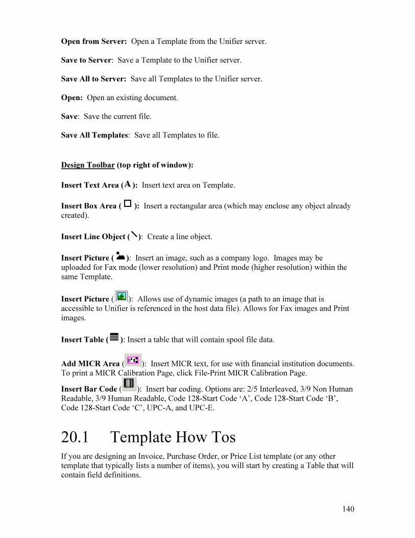
140
Open from Server: Open a Template from the Unifier server. Save to Server: Save a Template to the Unifier server. Save All to Server: Save all Templates to the Unifier server. Open: Open an existing document. Save: Save the current file. Save All Templates: Save all Templates to file.
Design Toolbar (top right of window):
Insert Text Area ( ): Insert text area on Template.
Insert Box Area ( ): Insert a rectangular area (which may enclose any object already created).
Insert Line Object ( ): Create a line object.
Insert Picture ( ): Insert an image, such as a company logo. Images may be uploaded for Fax mode (lower resolution) and Print mode (higher resolution) within the same Template.
Insert Picture ( ): Allows use of dynamic images (a path to an image that is accessible to Unifier is referenced in the host data file). Allows for Fax images and Print images.
Insert Table ( ): Insert a table that will contain spool file data.
Add MICR Area ( ): Insert MICR text, for use with financial institution documents. To print a MICR Calibration Page, click File-Print MICR Calibration Page.
Insert Bar Code ( ): Insert bar coding. Options are: 2/5 Interleaved, 3/9 Non Human Readable, 3/9 Human Readable, Code 128-Start Code ‘A’, Code 128-Start Code ‘B’, Code 128-Start Code ‘C’, UPC-A, and UPC-E.
20.1 Template How Tos If you are designing an Invoice, Purchase Order, or Price List template (or any other template that typically lists a number of items), you will start by creating a Table that will contain field definitions.

141
Tables consist of columns and rows divided into individual cells. Entering fields in each cell will enable you to organize spool data (such as line items, prices, units of measure, etc.) into an orderly grid-like design, and will ensure that spool data always lines up correctly on your Template.
The Repeat Field feature enables you to highlight an entire column and enter one field name instead of typing it into each cell. You can also resize and move the Table, split or merge cells within the Table, and shade individual cells or entire columns or rows.
You can then add Text Areas, insert a Picture for your company logo, add more Tables for additional data, add MICR or Bar Coding, or whatever else your Template design may call for.
Inserting a Table
Tables are a way to assemble data in an orderly grid fashion. Inserting repeat fields is a quick way to designate Template fields that will be repeated on more than one line (for line items, such as on a Purchase Order).
1. To insert a table, click on the Insert Table icon ( ). Drag your mouse anywhere in the blank Template area to form the outline of the table. When you release your mouse, the “Create Table” window will appear:
Figure 145
2. Enter the number of columns and rows for your table. Click ‘OK’ and the table
will appear. Now you are ready to enter field names. 3. To enter field names in the columns, left click directly above the column when
your cursor appears as a black arrow. This will cause the entire column to be highlighted in black.
4. Right click within the highlighted column and the following window will appear:
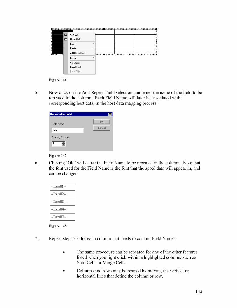
142
Figure 146
5. Now click on the Add Repeat Field selection, and enter the name of the field to be
repeated in the column. Each Field Name will later be associated with corresponding host data, in the host data mapping process.
Figure 147
6. Clicking ‘OK’ will cause the Field Name to be repeated in the column. Note that the font used for the Field Name is the font that the spool data will appear in, and can be changed.
Figure 148
7. Repeat steps 3-6 for each column that needs to contain Field Names.
• The same procedure can be repeated for any of the other features listed when you right click within a highlighted column, such as Split Cells or Merge Cells.
• Columns and rows may be resized by moving the vertical or horizontal lines that define the column or row.

143
• To move the table, click anywhere on the table so that the table is outlined in small lines. Place your cursor within the lines on the right edge or bottom edge of the table. Drag the table to the desired location and release your mouse.
Figure 149
• To resize the table, place your cursor on one corner of the table. Drag the corner to resize the table.
Inserting a Text Area
The text tool allows you to place a text box on the Template, enter and edit text, and format text.
1. Click on the Insert Text Area icon ( ). Drag your mouse in the blank Template area to form the outline of your text area. When you release the mouse, a solid box will appear.
2. Type or paste text into the area. Choose a desired font by right-clicking within the Text Area and clicking on the Fonts selection.
• To move or resize the text area, select it by clicking anywhere within the text area. Small lines will appear on the outside of your text box. Place your cursor within the lines on the edge of the table. Drag the table to the desired location and release your mouse. To resize the text area, place your cursor on one corner of the box. Drag the corner to resize the box.
• To change format of the text in the text box, right click within the box to bring up the format menu.
Inserting a Box Area A box can be used to enclose any object on the Template. To insert a box, click on the
Insert Box Area icon ( ). Drag your mouse in the area of the Template where you want a box to appear. When you release the mouse, a box will appear.
• To move or resize the box, select it by clicking within the box. To move the box, drag the box to the desired location and release the mouse. To resize the box, drag the vertical or horizontal handles.
• If you wish to enclose an object such as text, create the Text Box first, then draw a box around it. Items enclosed inside a box can only be edited when the box is temporarily moved.
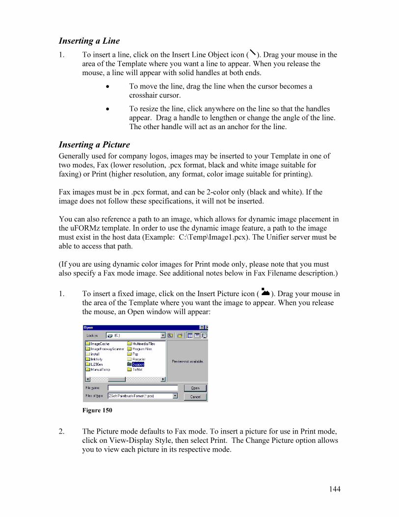
144
Inserting a Line
1. To insert a line, click on the Insert Line Object icon ( ). Drag your mouse in the area of the Template where you want a line to appear. When you release the mouse, a line will appear with solid handles at both ends.
• To move the line, drag the line when the cursor becomes a crosshair cursor.
• To resize the line, click anywhere on the line so that the handles appear. Drag a handle to lengthen or change the angle of the line. The other handle will act as an anchor for the line.
Inserting a Picture
Generally used for company logos, images may be inserted to your Template in one of two modes, Fax (lower resolution, .pcx format, black and white image suitable for faxing) or Print (higher resolution, any format, color image suitable for printing). Fax images must be in .pcx format, and can be 2-color only (black and white). If the image does not follow these specifications, it will not be inserted. You can also reference a path to an image, which allows for dynamic image placement in the uFORMz template. In order to use the dynamic image feature, a path to the image must exist in the host data (Example: C:\Temp\Image1.pcx). The Unifier server must be able to access that path. (If you are using dynamic color images for Print mode only, please note that you must also specify a Fax mode image. See additional notes below in Fax Filename description.)
1. To insert a fixed image, click on the Insert Picture icon ( ). Drag your mouse in the area of the Template where you want the image to appear. When you release the mouse, an Open window will appear:
Figure 150
2. The Picture mode defaults to Fax mode. To insert a picture for use in Print mode,
click on View-Display Style, then select Print. The Change Picture option allows you to view each picture in its respective mode.

145
Figure 151
3. Browse to the location on your PC where the image is stored. 4. Click ‘Open’. The image will be loaded into the area defined during the drag
process. The Picture may be resized or moved.
5. To insert a dynamic image, click on the second Insert Picture icon ( ). Drag your mouse in the area of the Template where you want the image to appear. The following window will appear:
Figure 152
Fax Filename: The Template field that will be used to map the dynamic image path in the host data file (Fax mode). The Fax Filename must reference a 2-color (black and white), .pcx format image.
You must specify a Fax Filename, even if you are only printing the image, so that a faxable image is created for viewing in Fax Center. The Fax Filename may be a template field (~FaxImage~) to be mapped to spool data that specifies the fax (black and white, .pcx format) image, or it can be a static path to a fax image (\\Server2\Public\FaxImage.pcx).

146
Print Filename: The Template field that will be used to map the dynamic image (color image) path in the host data file (Print mode). This image will only be used when printed, and can be any format.
Horizontal Alignment: The horizontal alignment of the image in relation to the drawn area on the Template.
Vertical Alignment: The vertical alignment of the image in relation to the drawn area on the Template.
Sizing: The sizing of the image in the drawn area on the Template.
None: Will not attempt to resize the original image to fit the drawn box.
Fit to Height: Will fit the image to the height of the drawn box, maintaining the original height/width ratio. Will alter the width of the image if necessary. (Depending on the height/width ratio of the image compared to that of the drawn box, the image may not fit completely and may be cut off.)
Fit to Width: Will fit the image to the width of the drawn box, maintaining the original height/width ratio. Will alter the height of the image if necessary. (Depending on the height/width ratio of the image compared to that of the drawn box, the image may not fit completely and may be cut off.)
Best Fit: Will fit the image horizontally and vertically to the drawn box, making the image appear as large as possible while still maintaining the original height/width ratio.
Stretch: Will fit the image to the height and width of the drawn box, changing the size of the image to fit in the drawn box exactly. (Depending on the height/width ratio of the image to that of the drawn box, the image may be stretched.)
Adding a MICR Area
1. Click on the MICR icon ( ).
2. Drag your mouse in the area of the Template where you want the MICR area to appear. When you release the mouse, the Bank Information Wizard window will appear:

147
Figure 153
3. Enter the Account Number, Check Number, and Routing Number information. Click OK. The MICR information will appear on the Template and may be resized or moved.
Adding a Barcode
1. Click on the Barcode icon ( ).
2. Drag your mouse in the area of the Template where you want the Barcode to appear. When you release the mouse, the Barcode Information window will appear:
Figure 154
3. Select the Barcode Style from the dropdown. 4. Enter the data or field name in the Data field. Select the Font Size and click OK.
The barcode information will appear on the Template and may be moved.

148
21. uFORMz Package
Definitions (AS400)
(Please use the simpler Windows method in Chapter 22 rather than this legacy AS400
method, which is included for documentation purposes only.)
Fast Path to Using uFormz (Legacy Method, from the AS400)
There are 4 basic steps to creating a uFORMz Package. The steps are:
• Create a Template (uFORMz Template Designer on your PC)
• Create a Package Definition (on AS400)
• Define Package Layers (on AS400)
• Build by Example (on AS400)
Create a Template
1. Create a Template in the uFORMz Template Designer and upload the Template (save) to the Unifier server.
Create a Package Definition
1. From the Unifier Main Menu, take Option 60 (Fax Table File Maint Menu), then Option 26 (uFORMz Definitions). This brings you to the uFORMz Package Definition screen.
2. Pressing F6 brings you to the Create uFORMz Package Definition screen. Enter a Package Name and Description.
3. Press Enter and your Package will appear in the uFORMz Package Definition/Package Selection screen.
Define Package Layers
Layers reference which Templates will make up your output. A Package can consist of multiple Layers based on input data.
1. Put a 12 (Work with Package) on the option line beside your Package in the Package Definition list and press Enter. This brings you to the uFORMz Layer Selection screen.
2. Press F6 to add a layer. This brings you to the uFORMz Layer Definition screen:

149
Figure 155
Field Descriptions:
• uFORMz Layer Name: Layer name.
• Layer Sequence: Sequence number of the Layer; determines the order in which the Layer is processed/selected.
• Description: Short text description of the uFORMz Layer.
• uFORMz Template to use: Name of the Template to associate with this Layer.
• Layer is Part of: Identifies whether the spooled file data extracted for this Layer should appear as part of the first page, the body, or the last page of the document. Valid values include F = First Page, B = Body, and L = Last Page.
• And/Or: Use this field as needed to indicate how the comparison tests are to be grouped. Type an AND to show that both the current test and the preceding test must be true. Type an OR to show that only one of the tests needs to be true. Leave this column blank if you are entering only one comparison test. If more than one test is entered, an AND is assumed if the field is left blank.
3. Press Enter. This returns you to the uFORMz Layer Selection screen, and you will see your Layer listed.
Build by Example
1. From the uFORMz Layer Selection screen, press F9 to Build by Example.
2. In the upper right corner of your screen, specify the outq name where your spool file resides. Locate the spool file and put a 1 on it to Select.
3. To add a new field:
• Position the spooled file so you can see the data from the spool file that will be in the field.
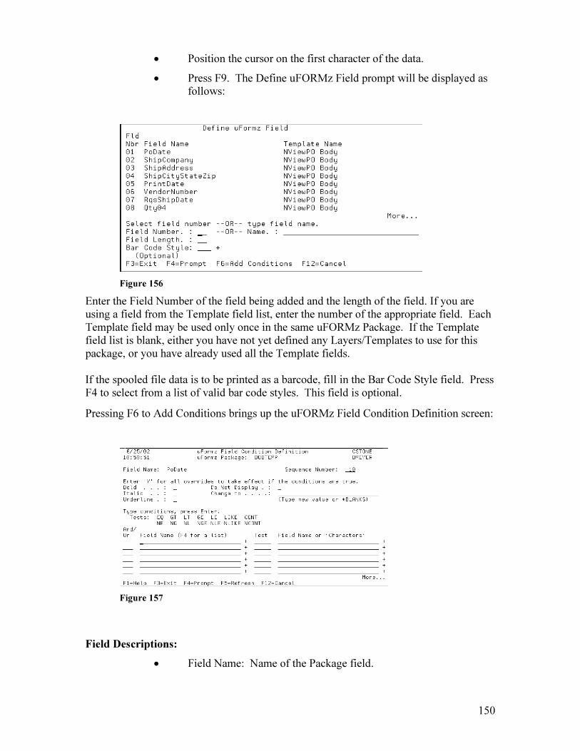
150
• Position the cursor on the first character of the data.
• Press F9. The Define uFORMz Field prompt will be displayed as follows:
Figure 156
Enter the Field Number of the field being added and the length of the field. If you are using a field from the Template field list, enter the number of the appropriate field. Each Template field may be used only once in the same uFORMz Package. If the Template field list is blank, either you have not yet defined any Layers/Templates to use for this package, or you have already used all the Template fields. If the spooled file data is to be printed as a barcode, fill in the Bar Code Style field. Press F4 to select from a list of valid bar code styles. This field is optional.
Pressing F6 to Add Conditions brings up the uFORMz Field Condition Definition screen:
Figure 157
Field Descriptions:
• Field Name: Name of the Package field.
151
• Sequence Number: Controls the order in which the sets of field conditions are processed. uFORMz will use the attributes of the first set of field conditions to be found true.
The following fields are used to override the formatting option(s) specified in the template.
• Bold: Use this option to print the field data in bold type. Valid values are ‘Y’ or blank.
• Italic: Use this option to print the field data in italics. Valid values are 'Y' or blank
• Underline: Use this option to print a line under the field data.Valid values are 'Y' or blank.
• Do Not Display: Use this option to suppress printing of the field data. Valid values are 'Y' or blank.
• Change To: Use this option to change the value of the field data. You may type a new value to be printed on the uFORMz page, or type '*BLANKS'.
Field Conditions: And/Or: Use this field as needed to indicate how the comparison tests are to be grouped. Type an AND to show that both the current test and the preceding test must be true. Type an OR to show that only one of the tests needs to be true. Leave this column blank if you are entering only one comparison test. If more than one test is entered, an AND is assumed if the field is left blank.
For layers with multiple comparison tests:
-- If AND 's are used, only records that pass all comparison tests will be selected.
-- If OR 's are used, all records that pass at least one test will be selected.
-- If both AND 's and OR 's are used, each OR starts a new group of comparison tests. Records that pass all comparison tests in at least one group will be selected. Field Name: Type the name of the field to be tested. Use only fields which have been defined for this uFORMz package. Press F4 to select from a list of valid field names. Test:
EQ Equal
GT Greater than
LT Less than
GE Greater than or equal to
LE Less than or equal to
LIKE Value1 starts the same way as Value2
152
CONT Value2 contains Value1
NE Not equal
NG Not greater than
NL Not less than
NGE Not greater than or equal to
NLE Not less than or equal to
NLIKE Value1 does not start the same way as Value2
NCONT Value2 does not contain Value1
Field Name or 'Characters': For each test, type the value to be compared with the test field. The value can be either a constant value or a field name from the current uFORMz package. Press F4 to select from a list of valid field names.
Continue highlighting fields by placing your cursor in the specified cursor position. Press F9, then enter the field number of the corresponding uFORMz Field name and Field Length.
Now press F3 to return to the uFORMz Layer Selection screen. The Package is now ready for faxing.
Faxing a Package
There are several Unifier attributes associated with a spool file. One of these is ‘Form Overlay Name’. This can be specified in the spool file Form Type, or may have been specified in the SndAPIFax or EzAPI Forms Overlay Image parameter. The Form Overlay Name can also be specified at the time of faxing in the Other Attributes screen (F8 from the Assign Destinations to Fax screen).
When you are faxing your spool file, enter the Package name as the Form Overlay name, or specify the Form Type of the spool file as the Package name. This causes the Package to be faxed with the respective spool file data.
Storing a Package
When the Package has been created, and you return to the Package Selection screen, you will see your Package listed. The entire Package is sent to the Unifier server at this point.
153
22. uFORMz Package
Definitions (Windows) Fast Path to Using uFormz (from Windows)
There are 4 steps to creating a uFORMz Package. The steps are:
• Create a Template
• Create a Package Definition
• Define Layers, and
• Map the Template Fields to Host Data
You must first design a Template using the uFORMz Template Designer (see Chapter 20).
When you have completed your Template, open the uFORMz Package Definition application to create a Package Definition. The following window will appear:
Figure 158
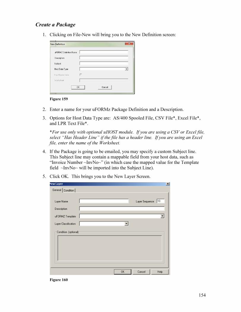
154
Create a Package
1. Clicking on File-New will bring you to the New Definition screen:
Figure 159
2. Enter a name for your uFORMz Package Definition and a Description.
3. Options for Host Data Type are: AS/400 Spooled File, CSV File*, Excel File*, and LPR Text File*.
*For use only with optional uHOST module. If you are using a CSV or Excel file, select “Has Header Line” if the file has a header line. If you are using an Excel
file, enter the name of the Worksheet.
4. If the Package is going to be emailed, you may specify a custom Subject line. This Subject line may contain a mappable field from your host data, such as “Invoice Number ~InvNo~” (in which case the mapped value for the Template field ~InvNo~ will be imported into the Subject Line).
5. Click OK. This brings you to the New Layer Screen.
Figure 160

155
Define Package Layers
The Layer identifies the Template that is to be used for this Package. It also identifies any conditions that determine if this Layer should be output. The output pages may consist of several Layers, and each Layer may reference a different Template.
1. When you create a Package Definition, you will be presented with the Layer Properties window. (To create additional layers after you create the first Layer, right click in the Layer pane on the upper left of your screen, then select New Layer.)
Figure 161
2. Enter a Layer Name, a Layer Sequence (for Packages with multiple Layers, this determines which Layer is to be used first), and a Description of the Layer.
3. From the uFORMz Template dropdown, select the uFORMz Template you have designed for this Layer.
4. From the Layer Classification dropdown, choose what part of the printed output this Layer defines. Options are First Page, Body, and Last Page, as Packages may consist of multiple pages with different output on each page.
5. If this Layer is to be conditioned, click the Conditions tab. This brings you to the Layer Properties screen.

156
Figure 162
Conditioning Layers
Layers are conditioned based on field values that are defined on the Template specified for this Layer. Conditions determine whether a particular Layer is to be used or not.
To add a Condition:
• Click the Add button in the center of the window.
• Choose the Template Field from the Operand 1 dropdown in the Subcondition Item section of the window (at the bottom of your screen).
• Choose the Operator value.
• Choose the comparison value in the Operand 2 dropdown. If you wish to enter a constant value, enter it in the Operand 2 field.
• Click Apply Changes at the bottom of your screen. You will now see the Condition appear in the upper part of the screen. You may edit or delete the entry by highlighting it, then clicking Edit or Delete.
• When you are finished entering Conditions, click OK. Your condition(s) will now appear in the New Layer window.
Map Template Fields
Now that your Layer has been defined, all template fields for the templates you selected will now show up in the Fields window, and you are now ready to map Template fields to your host data.
The first step in mapping Template fields to host data is to send your host data to the Unifier.

157
1. For AS400 spool files, send the spool file from your AS400 to destination *UNIFIER.
2. For ASCII text files (using the optional uHOST module), this is done by executing an LPD command to an LPR Print Queue that has been defined on the Unifier, in the Administrator Tool – Miscellaneous section. The format of the LPD command is:
LPR -S ‘IP address of Unifier” -P ‘Name of LPD Print Q’ ‘Path of text file’
Example: LPR –S 10.1.2.140 –P AR-Invoices C:\Temp\Invoice.txt
For CSV and Excel files (using the optional uHOST module), select File – Open
Data file, and select the file to open it.
3. Now you can view the host data in the uFORMz Package Definition screen:
• Open the uFORMz Package Definition you created above.
• Click File-Open Data File. This brings you to the following screen:
Figure 163
• Highlight the host data file and click OK.
• The host data now appears in the uFORMz Package Definition screen on the right side of your window.
4. Now that you are viewing your host data, you can map Template fields to the data. Template fields for all templates named in the Layers you have created appear in the Fields window.
5. Drag a field name from the ‘Fields’ window at the bottom left of your screen over the host data that defines this field on the right area of your screen. You will now see a highlighted field over your host data, and you can adjust it to fit your host data. (You will need to know the maximum possible number of characters for each host data field, so that no characters are cut off or ignored.)

158
For Excel and CSV files*, drag a field name from the ‘Fields’ window to the top
of the corresponding data column. This will cause the entire column to be selected
for that field value. Repeat fields will be designated as one field, with 3 trailing
periods (…).
When a field is defined, you will be presented with the following window:
Figure 164
Field Name: The name of the template field you just defined.
From Data File: Column Index is the column number for the mapped field, if no
header file exists. If a header line exists and was specified, Column Name is the
header name of the mapped column, as it appears on your named Excel
worksheet.
Calculated Field: If this is checked instead of From Data File, the mapped field
will contain a calculated value for Current Page, Current Date, or Current Time.
To add field conditions, select the Conditions tab, and follow the instructions for
Conditioning Package Fields in the next section.
Select the Data Type tab to specify data formatting properties. Select the data
type form the dropdown, then choose the applicable format.
Figure 165
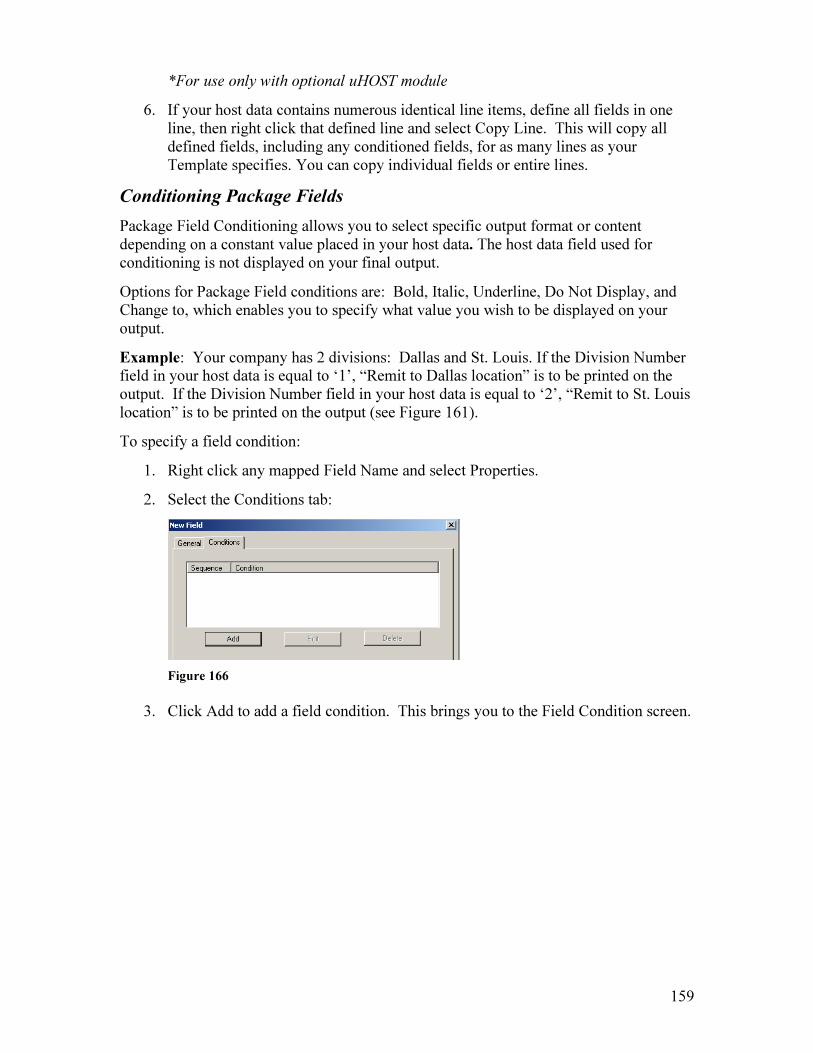
159
*For use only with optional uHOST module
6. If your host data contains numerous identical line items, define all fields in one line, then right click that defined line and select Copy Line. This will copy all defined fields, including any conditioned fields, for as many lines as your Template specifies. You can copy individual fields or entire lines.
Conditioning Package Fields
Package Field Conditioning allows you to select specific output format or content depending on a constant value placed in your host data. The host data field used for conditioning is not displayed on your final output.
Options for Package Field conditions are: Bold, Italic, Underline, Do Not Display, and Change to, which enables you to specify what value you wish to be displayed on your output.
Example: Your company has 2 divisions: Dallas and St. Louis. If the Division Number field in your host data is equal to ‘1’, “Remit to Dallas location” is to be printed on the output. If the Division Number field in your host data is equal to ‘2’, “Remit to St. Louis location” is to be printed on the output (see Figure 161).
To specify a field condition:
1. Right click any mapped Field Name and select Properties.
2. Select the Conditions tab:
Figure 166
3. Click Add to add a field condition. This brings you to the Field Condition screen.

160
Figure 167
4. Click the Add button in the center of the window. This will allow you to select which field to condition, and what value to condition it on.
5. Choose the Template Field you wish to condition from the Operand 1 dropdown in the Subcondition Item section of the window (at the bottom of your screen).
6. Choose the Operator value.
7. Choose the comparison value in the Operand 2 dropdown. This can be either a Template field or a value of your own choosing. If you wish to enter a constant value, enter it in the Operand 2 field.
8. Select the Result for the conditioned field in the lower portion of your screen.
9. Click Apply Changes. Your conditioned field and its values will now be listed in the Condition window. You may edit or delete the entry by highlighting it, then clicking Edit or Delete.
10. When you are finished, click OK.
Example: For this condition Example, the host data contains a field called Division Number. If there is a 1 in that field, then the Result of this condition is for “Remit to Dallas Location” to be printed.

161
Figure 168
Faxing a Package
There are several Unifier attributes associated with a spool file. One of these is “Form Overlay Name”. This is specified either by the spool file Formtype parameter, or may have been specified in the SndAPIFax or EzAPI Forms Overlay Image parameter. The Form Overlay Name can also be specified at the time of faxing in the Other Attributes screen (F8 from the Assign Destinations to Fax screen on the Unifier400).
Enter the Package name as the Form Overlay name, or specify the Formtype of the spool file as the Package name. This causes the Package to be faxed with the respective spool file data.
For Excel and CSV files*, once a file is placed into the Hot Folder, it will then move to
Server EzAPI, which specifies the uFORMz Package to be used.
*For use only with optional uHOST module
Exporting/Importing a Package
Once a Package definition has been completed, the entire Package can be exported or saved to any location on your network. Packages may be imported to a Unifier from any saved location. Exporting and Importing a Package is done from the uFORMz Package Definition application on a client PC.

162
To export a Package, select the Export Package icon ( ). You will be presented with the following window:
Figure 169
Highlight the Package you wish to export in the Current Definitions area. Click Browse to browse to the location you wish to save the Package. The Package will be stored as a .pkg file.
To import a Package, select the Import Package icon. Browse to the Package you wish to Import. After you locate the Package name and click OK, you will be presented with the following window:
Figure 170
Click the Import button to Import the Package to your Unifier.
163
23. uSIGN Install Guide (uSIGN is an optional module used for inserting signatures onto documents with the
uSIGN Signature Pad)
Installation
1. Install the uSIGN signature pad by plugging it into a USB port on your PC.
2. Run the Setup.exe file to install the application. You may need to be logged on as
Administrator, depending on your company’s restrictions.
Settings
1. Open the uSIGN application and click on File-Settings.
2. Browse to the Source Path location for the documents that you wish to insert a
signature on. Make sure you have full permissions to this folder. (If you are
using uSTOR/Document Mountain, this will be the folder that Sent Faxes are sent
to, from your Unifier server setup in the Unifier Administrator Tool -
Miscellaneous.)
3. Now browse to the Target Path location, which is where the signed documents
will be sent , after they are processed by uSIGN. (If you are using
uSTOR/Document Mountain, this will be the Import folder on your
uSTOR/Document Mountain server.)
4. Click Insert. This makes the Source and Target locations appear in the Path
Locations window.
5. Now click the Name field in the Path Location you just created, and enter a name
for this Path Location.
6. Set the desired times for Export Options. This is the amount of time or number of
documents that must be reached before items are viewable in the uSIGN
application, after they have been placed in the Source Path location.
7. When you are done entering the Source and Target Location path and have edited
the Export Options, click OK.

164
Signature Templates
1. To create a signature template, you must first view a document in the uSIGN
application. Click Search to return a list of all available documents in the chosen
Source Path location.
• If you created more than one Source Path location, then choose the desired
location in the Group dropdown
• To select multiple documents, use the Control key. The next document
will be shown after you click Finalize.
2. Once you have opened a document, click Create under Document Templates to
create a new Signature Template.
Figure 171
• The Signature Template determines the location on the page where your
signature(s) will be placed.
3. Under Field Information, enter a name for the signature, then click Insert.
• Right clicking on the Field Name entry allows you to choose a color for
this signature, or to use the Session Signature (onetime signature that is
entered ad hoc).

165
4. Use your mouse to draw the signature location on your document in the Viewer
portion of the window.
Figure 172
• Field locations may be entered using coordinates instead of using your
mouse to draw the location.
• Each Signature Template may contain multiple locations of the same
signature, as well as multiple signatures, designated by unique Field
Names.
• In the Page Location section, enter a value in the Fixed Page box if the
signature is to appear on the same page every time (counted from page 1).
If the signature is to be placed on a particular page that is counted from the
end, then check the From End box after entering a Fixed Page value.
• Select Prompt if you wish to select the page where the signature is to be
placed each time you process a document.
• To delete a signature location and recreate it, right click on the existing
signature location, and click Delete.
• When you are finished selecting the signature location(s), click OK.
Entering Signatures
1. Click on the Template Name under Document Templates.
2. In the Signatures section, select the Field Name for each signature.
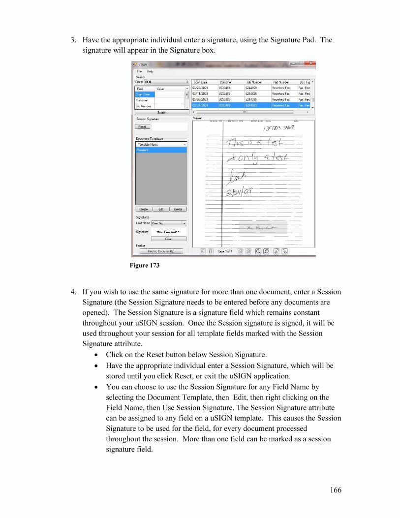
166
3. Have the appropriate individual enter a signature, using the Signature Pad. The
signature will appear in the Signature box.
Figure 173
4. If you wish to use the same signature for more than one document, enter a Session
Signature (the Session Signature needs to be entered before any documents are
opened). The Session Signature is a signature field which remains constant
throughout your uSIGN session. Once the Session signature is signed, it will be
used throughout your session for all template fields marked with the Session
Signature attribute.
• Click on the Reset button below Session Signature.
• Have the appropriate individual enter a Session Signature, which will be
stored until you click Reset, or exit the uSIGN application.
• You can choose to use the Session Signature for any Field Name by
selecting the Document Template, then Edit, then right clicking on the
Field Name, then Use Session Signature. The Session Signature attribute
can be assigned to any field on a uSIGN template. This causes the Session
Signature to be used for the field, for every document processed
throughout the session. More than one field can be marked as a session
signature field.

167
• Regular template fields require a signature to be entered on the signature
pad once for every document processed
• Session Signature template fields require a signature to be entered on the
signature pad once for a uSIGN session, and only before a document is
opened
5. You may select multiple documents that will have the same signatures for each
individual Field Name in your template.
• To select multiple documents that will have the same signatures for each
individual Field Name, hold the Shift key, then select the documents.
• Enter the signature just as you would for a single document.
• When you click Finalize, the same signature will be placed on each
selected document.
6. After you are finished entering signatures, click Finalize Document.
Figure 174
• If you selected ‘Prompt’ as a Signature Placement option, you will now be
prompted for the page number for the signature. Enter the page number in
the Page Entry section and click OK.

168
• Click Finish to accept the document. This moves it to the specified Target
Path location. If you selected multiple documents to be signed, the next
document will then appear in the uSIGN application.
• All signatures are cleared when you click Finish. A new signature must be
entered for each document (unless it is a Session Signature).
169
24. uMAIL2FAX
(uMAIL2FAX is an optional module that allows a fax number to be specified in an email
address or email subject line, within your email client.)
uMAIL2FAX allows you to send emails from any source to the Unifier server to be faxed. This eliminates the need to install the Unifier client on desktops, and allows any device that is capable of communicating with your mail server to send faxes.
uMAIL2FAX can be configured on Exchange Server (2007/2010) or any mail server that has POP3 enabled. After the email is passed to Unifier, the email attachments are faxed with parameters parsed from components of the email.
You can configure your Exchange Server to route emails to Unifier based on the ‘To’ email address. Unifier acts as a mail server and parses the components of the email, then faxes the attachment(s) accordingly.
File formats currently supported for faxing documents via email include:
• PDF Documents (PDF)
• TIFF Images (TIF, TIFF, FAX)
• JPEG Images (JPG, JPEG)
• PNG Images (PNG)
• BMP Images (BMP)
• GIF Images (GIF)
• Rich Text Documents (RTF)
• Comma-Separated Value (CSV)
• XPS Documents (XPS)
• HTML Files (HTM, HTML)
• Text Files (TXT)
• Word Documents and Templates (DOCX, DOCM, DOC, DOTX, DOTM, DOT)
• Excel Workbooks and Templates (XLSX, XLSM, XLS, XLTX, XLTM, XLT, XLSB)
• PowerPoint Presentations, Shows, and Templates (PPTX, PPTM, PPT, PPSX, PP
SM, PPS, POTX, POTM, POT)
• Visio Drawings (VSD)
(See Note below)
Note: Faxing Office documents requires Microsoft Office to be installed on the Unifier server.

170
How does it work?
1. Based on your mail server configuration, Unifier will either receive email forwarded from an Exchange server, or retrieve mail from a specific mailbox on a POP3 server.
2. The fax number is specified in either the email address (Exchange) or the subject line of the email (POP3).
3. Unifier parses out the fax number and creates a faxable image from the email attachment/s. The message body of the email is used as the message body of the fax cover page.
4. The email attachment is then faxed to the destination.
Configuring uMAIL2FAX on the Unifier
1. Open the Admin Tool on the Unifier server.
2. Select Edit > SysInfo Table.
3. Click the New System icon ( ) on the toolbar. This will bring you to the
following window:
Field Descriptions
Component ID: Enter a unique ID for this component. Make sure the Component ID is not already being used by another Unifier Component. IP Address: Enter the IP address of the Unifier server.

171
Port: Enter the port over which the component will operate. This port should be unique, and should not be used by any other component in the SysInfo Table. Recommended default is 8070. Description: Enter a description for this component.
Primary Cluster Controller: Select your company’s existing Cluster Controller from the dropdown. Server Type: Select ‘6 – uMAIL2FAX Service’.
4. Click ‘Save’ at the top right of the window, but do not exit the Admin Tool.
5. Click Edit > System Defaults. This will bring you to the following window:
6. Select System Information on the left, in the Category table.
7. In the uMAIL2FAX Service Component ID field, choose the component ID that you
just created from the dropdown, then select Save Changes at the bottom of the
Category window. If the new component is not listed in the dropdown, close the
Admin Tool and reopen it.
(If you are not configuring an Exchange connector, skip to Step 11. If you are
configuring an Exchange connector, continue with Step 8.)
8. Select Email/SMTP Information on the left, in the Category table. This will bring
you to the following window:
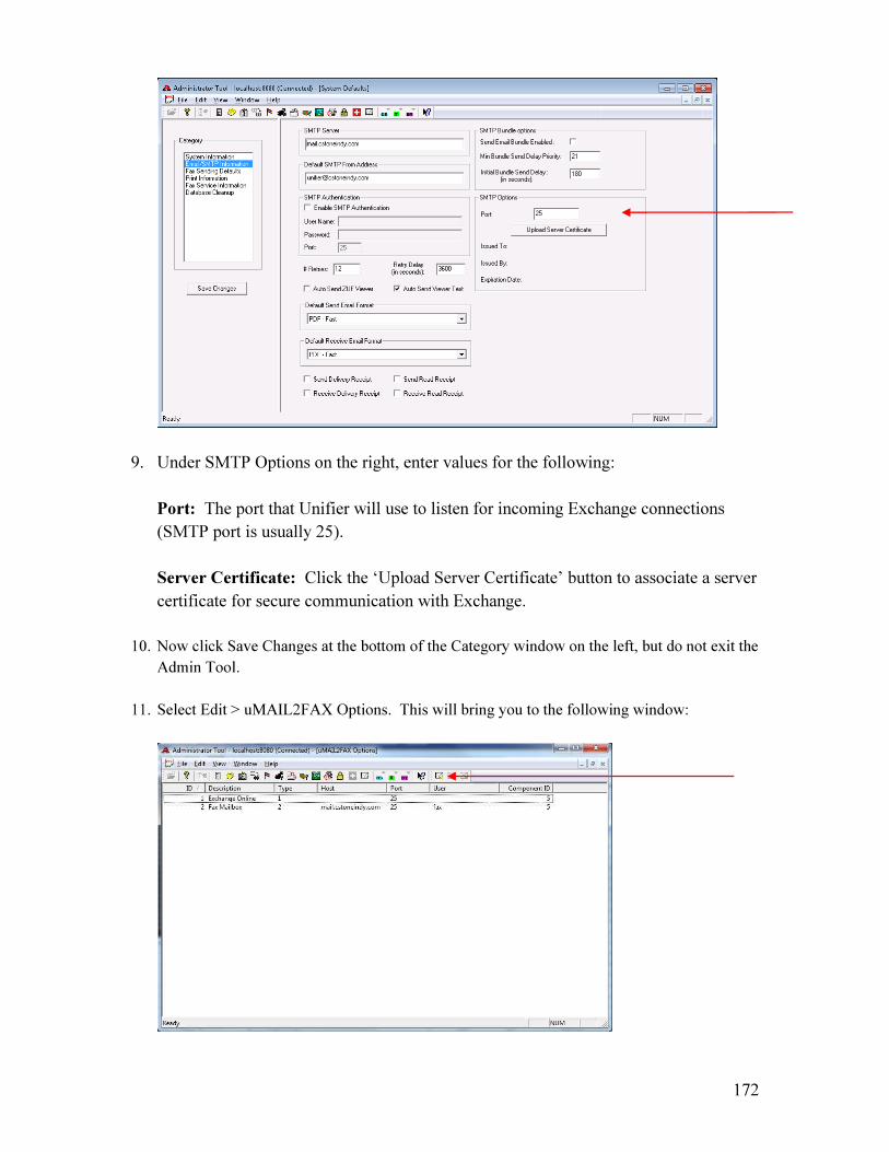
172
9. Under SMTP Options on the right, enter values for the following:
Port: The port that Unifier will use to listen for incoming Exchange connections
(SMTP port is usually 25).
Server Certificate: Click the ‘Upload Server Certificate’ button to associate a server
certificate for secure communication with Exchange.
10. Now click Save Changes at the bottom of the Category window on the left, but do not exit the
Admin Tool.
11. Select Edit > uMAIL2FAX Options. This will bring you to the following window:

173
12. Click the New uMAIL2FAX button on the toolbar. This will bring you to the following
window:
Field Descriptions:
uMAIL2FAX ID: Enter the ID number to be used for this uMAIL2FAX component. (The ID number can be the same as the Component number in the SysInfo Table.)
Description: Enter a description. Type: To receive email forwarded from an Exchange server, select SMTP Connector.
To retrieve mail from a specific mailbox, select POP3. uMAIL2FAX Component: Select the component previously created in the SysInfo
Table.
Default User: The user profile to use if the from email address does not match that of a user that is currently set up in the Unifier User Profile Tool.
Always Use Default User: Select this option to always use the username specified in the Default User field as the sender, regardless of who sent the email.
174
Always Use Cover Page: Forces use of a cover page, regardless of the user default. Use of a cover page ensures that the email body is included with the fax.
SMTP Options
These fields will show up if you have selected SMTP Connector in the Type field, and are only applicable to Exchange setup:
Domain Filter: The domain name to be used for emails (Example: unifierfax.com). Only domains which match the Domain Filter specified here will be accepted.
POP3 Options
These fields will show up if you have selected POP3 in the Type field, and are only applicable to POP3 setup:
Hostname: The SMTP server that the Unifier will connect with. Port: The port over which to connect to the SMTP server. Interval (in minutes): The interval at which Unifier will check for new mail. Username: The username for the POP3 account on the SMTP server. Password: The password for the POP3 account on the SMTP server.
13. Click OK.
14. Restart the server for all changes to take effect (from the Admin Tool, select File >
Reboot Server).
If you are using POP3 mail server, then your setup is now complete. If you are using
Exchange, you must configure your Exchange server (see Appendix 1 and Appendix 2 on
the following pages for configuration instructions).

175
Appendix 1: Configuring uMAIL2FAX on Exchange 2007/2010
1. Start the Exchange Management Console.
2. In the console tree, click the Organization Configuration – Hub Transport node.
3. In the action pane, click New Send Connector.
4. On the Introduction page, enter the name of the new send connector, then select the
Custom option in the ‘Select the intended use…’ dropdown. Then click ‘Next’.

176
5. On the Address Space page, click Add.
6. In the Address field, enter the desired domain, then click OK. All emails sent to this
domain will be forwarded to the Unifier server (Example: unifier.com).
7. Repeat steps 5 and 6 to add additional address spaces. When you are finished, click
Next on the Address Space page.

177
8. On the Network Settings page, select ‘Route mail through the following smart hosts’.
9. Click ‘Add’. On the Add Smart Host dialog, enter the IP Address or fully qualified
domain name of the Unifier server in the IP Address field, then click OK.
10. On the Network Settings page, click Next.
11. Under ‘Configure Smart Host Authentication Settings’, select the appropriate authentication type, then click Next.

178
12. On the Source Server page, select the Exchange server that you are associating the new connector to, then click Next.
13. On the New Connector page, review the settings to verify they are correct and then click New.
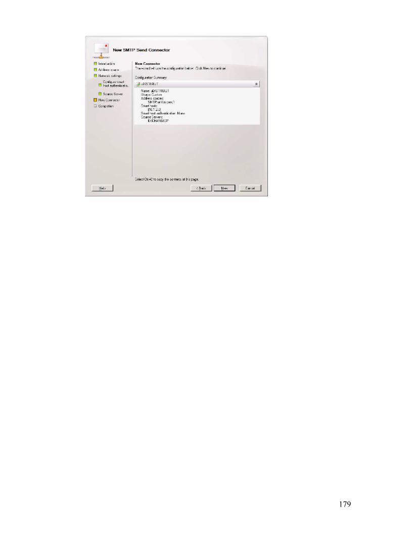
179

180
Appendix 2: Configuring uMAIL2FAX on Exchange Online
1. Logon to Office 365 as an administrator.
2. Select ‘Exchange’ from the Admin menu.
3. Under the Mail Flow heading on the right, click ‘Connectors’.
4. Click the ‘+’ button to add a new Outbound Connector.

181
5. Enter a name for the connector in the Name field. Make sure the ‘Enable outbound
connector’ box is checked, and select ‘On-premises’ under Connector Type.
6. Select the appropriate Connection Security option:
Check ‘Opportunistic TLS’ if secure transmission is not required. If you select any of
the other options, a server certificate will be required on the Unifier server. (For
information on server certificates: https://www.digicert.com/iis-ssl-encryption.htm)

182
7. Select ‘Route mail through smart hosts’ in the Outbound Delivery section. Click the
Add button (indicated by the +) to add a Smart Host.
8. Enter the IPv4 Address or fully qualified domain name of the Unifier server that you
will be sending emails to.
9. Under the Recipient domains section, click the Add button (indicated by +) and enter
the desired domain. All emails sent to this domain will be forwarded to the Unifier
server (Example: @unifier.com).
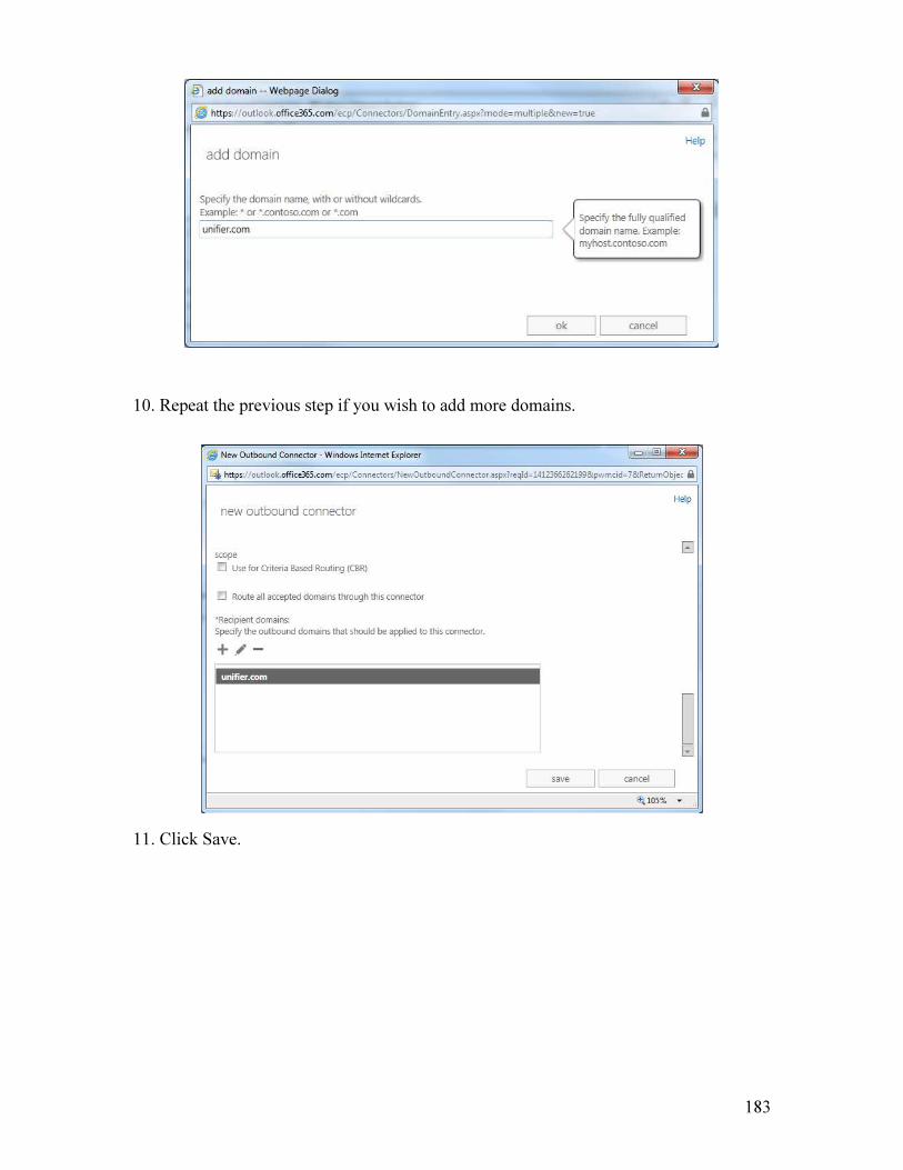
183
10. Repeat the previous step if you wish to add more domains.
11. Click Save.
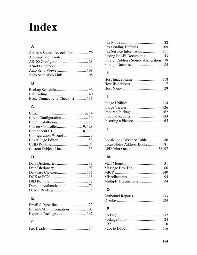
184
Index
A
Address Source Association ............... 79 Administrator Tools ............................ 73 AS400 Configuration .......................... 28 AS400 Upgrades ................................. 27 Auto Send Viewer ............................. 108 Auto Send Web Link ........................ 108
B
Backup Schedule ................................. 92 Bar Coding ........................................ 140 Basic Connectivity Checklist ............ 131
C
Citrix ............................................. 13, 14 Client Configuration ........................... 16 Client Installation ................................ 13 Cluster Controller.......................... 9, 128 Component ID ............................... 8, 113 Configuration Wizard ........................... 7 Cover Page Editor ............................... 53 CSID Routing...................................... 74 Custom Subject Line ........................... 35
D
Data Dictionaries ................................ 33 Data Dictionary ................................... 97 Database Cleanup.............................. 111 DCX to PCX ..................................... 115 DID Routing........................................ 75 Domain Authentication ....................... 76 DTMF Routing.................................... 78
E
Email Subject line ............................... 23 Email/SMTP Information ................. 107 Export a Package............................... 162
F
Fax Header .......................................... 54
Fax Mode ............................................ 88 Fax Sending Defaults ........................ 109 Fax Service Information ................... 111 Faxing EzAPI Documents................... 43 Foreign Address Source Association .. 79 Foreign Database ................................ 84
H
Host Image Name ............................. 118 Host IP Address .................................. 17 Host Name .......................................... 28
I
Image Utilities ................................... 114 Image Viewer .................................... 126 Import a Package............................... 162 Inbound Reports ................................ 133 Inserting a Picture ............................... 65
L
Local/Long Distance Table ................. 86 Lotus Notes Address Books ................ 81 LPD Print Queue ........................... 38, 97
M
Mail Merge.......................................... 31 Message Box Tool .............................. 66 MICR ................................................ 140 Miscellaneous ..................................... 94 Multiple Destinations .......................... 24
O
Outbound Reports ............................. 133 Overlay .............................................. 124
P
Package ............................................. 137 Package Editor .................................... 24 PBX ..................................................... 10 PCX to DCX ..................................... 116

185
Permissions ......................................... 49 Picture Tool ......................................... 65 Policy Rights ....................................... 51 Port Assignment .................................. 89 Port Group ........................................... 88 Port/Port Group Table ......................... 87 Prefix ................................................... 88 Primary Address Field ........................ 42 Print Hard Copy .................................. 47 Print Information ............................... 110 Printer Alias ........................................ 91 Printers ................................................ 30
Q
Quick Notes ........................................ 22
R
Receive Route User............................. 88 Replace Server Prefix/Suffix .............. 87 Report Component ID ......................... 88 Reports .............................................. 133 Routing Received Faxes to Email ....... 90
S
Save for Later ...................................... 24 Schedule Backup ................................. 92 Secondary Address.............................. 42 Send Display ....................................... 18 Send Notification ................................ 47 Send Package ...................................... 26 Sending Quick Notes .......................... 22 Server Area Code ................................ 87 Server Exchange ................................. 87 Server Reports ................................... 133 Server Updates .................................... 14
Setting Up A Printer............................ 30 Shared Address Books ...................... 102 SMTP Relay Server .......................... 108 Snap to Grid Tool................................ 70 Source Channel ................................... 29 Storing a Package .............................. 152 Subject Field ....................................... 35 Suffix................................................... 88 System Alert........................................ 48 System Defaults ................................ 106 System Information ........................... 107
T
Target Channel .................................... 29 Terminal Services ......................... 13, 14 Text Output Settings ........................... 31 Text Tool ............................................. 56 Typical Setup ...................................... 13
U
uFormz Designer ............................... 139 uFormz Layer Definition .................. 148 uFormz Package Definitions (PC) .... 153 uMAIL2FAX……………………….169 UnAssigned Port Group ...................... 88 Unifier Capture ................................... 24 Unifier Monitor ................................. 128 Unifier uDistribut TS Capture ............ 14 Upload Image to Host ....................... 118 User Profile ................................... 46, 48 User Profile Administrator .................. 45 User Reports...................................... 133
W
Windows Mail Merge ......................... 31