Embed Size (px)
Citation preview
AS/400 Disk Storage Topics and Tools
Susan Powers, Bill Bradshaw, Pat Lozano, Olga T. Saldivar, Satid Singkorapoom
International Technical Support Organization
SG24-5693-00
www.redbooks.ibm.com

International Technical Support Organization SG24-5693-00
AS/400 Disk Storage Topics and Tools
April 2000
© Copyright International Business Machines Corporation 2000. All rights reserved.Note to U.S Government Users - Documentation related to restricted rights - Use, duplication or disclosure is subject to restrictionsset forth in GSA ADP Schedule Contract with IBM Corp.
First Edition (April 2000)
This edition applies to Version 4 Release 4 of OS/400, AS/400 Operating System, Program Number 5769-SS1.
Comments may be addressed to:IBM Corporation, International Technical Support OrganizationDept. JLU Building 107-23605 Highway 52NRochester, Minnesota 55901-7829
When you send information to IBM, you grant IBM a non-exclusive right to use or distribute the information in anyway it believes appropriate without incurring any obligation to you.
Before using this information and the product it supports, be sure to read the general information in Appendix F,“Special notices” on page 219.
Take Note!
Contents
Figures . . . . . . . . . . . . . . . . . . . . . . . . . . . . . . . . . . . . . . . . . . . . . . . . . . . . . . vii
Tables . . . . . . . . . . . . . . . . . . . . . . . . . . . . . . . . . . . . . . . . . . . . . . . . . . . . . . . xi
Preface . . . . . . . . . . . . . . . . . . . . . . . . . . . . . . . . . . . . . . . . . . . . . . . . . . . . . xiiiThe team that wrote this redbook . . . . . . . . . . . . . . . . . . . . . . . . . . . . . . . . . . . . . . xiiiComments welcome . . . . . . . . . . . . . . . . . . . . . . . . . . . . . . . . . . . . . . . . . . . . . . . . xv
Part 1. Storage architectures and components of AS/400 DASD . . . . . . . . . . . . . . . . . . . . . . . . . . .1
Chapter 1. System architecture . . . . . . . . . . . . . . . . . . . . . . . . . . . . . . . . . . .31.1 Components of the AS/400 system . . . . . . . . . . . . . . . . . . . . . . . . . . . . . . .31.2 Licensed Internal Code (LIC) . . . . . . . . . . . . . . . . . . . . . . . . . . . . . . . . . . .5
1.2.1 Technology Independent Machine Interface . . . . . . . . . . . . . . . . . . . .61.2.2 PLIC on AS/400e series systems (V4R4) . . . . . . . . . . . . . . . . . . . . . .71.2.3 Vertical Licensed Internal Code (VLIC) . . . . . . . . . . . . . . . . . . . . . . . .91.2.4 Horizontal Licensed Internal Code (HLIC) . . . . . . . . . . . . . . . . . . . . . .9
1.3 AS/400 addressing . . . . . . . . . . . . . . . . . . . . . . . . . . . . . . . . . . . . . . . . . .101.3.1 Physical location . . . . . . . . . . . . . . . . . . . . . . . . . . . . . . . . . . . . . . . .101.3.2 Logical addressing . . . . . . . . . . . . . . . . . . . . . . . . . . . . . . . . . . . . . .111.3.3 Direct select address (DSA) and unit address . . . . . . . . . . . . . . . . . .11
1.4 Summary . . . . . . . . . . . . . . . . . . . . . . . . . . . . . . . . . . . . . . . . . . . . . . . . .17
Chapter 2. Storage architecture . . . . . . . . . . . . . . . . . . . . . . . . . . . . . . . . . .192.1 Direct access storage device (DASD) . . . . . . . . . . . . . . . . . . . . . . . . . . . .192.2 Cache . . . . . . . . . . . . . . . . . . . . . . . . . . . . . . . . . . . . . . . . . . . . . . . . . . . .19
2.2.1 Expert cache . . . . . . . . . . . . . . . . . . . . . . . . . . . . . . . . . . . . . . . . . . .192.2.2 Extended Adaptive Cache (EAC). . . . . . . . . . . . . . . . . . . . . . . . . . . .20
2.3 Logical partitioning on the AS/400 system. . . . . . . . . . . . . . . . . . . . . . . . .222.4 Data storage and management on the AS/400 system . . . . . . . . . . . . . . .23
2.4.1 Data management . . . . . . . . . . . . . . . . . . . . . . . . . . . . . . . . . . . . . . .232.4.2 Database management . . . . . . . . . . . . . . . . . . . . . . . . . . . . . . . . . . .23
2.5 Integrated File System . . . . . . . . . . . . . . . . . . . . . . . . . . . . . . . . . . . . . . .242.6 Digital Versatile Disk (DVD) on the AS/400 system . . . . . . . . . . . . . . . . . .24
2.6.1 How DVD applies to the AS/400 system . . . . . . . . . . . . . . . . . . . . . .242.7 Storage Area Network (SAN) . . . . . . . . . . . . . . . . . . . . . . . . . . . . . . . . . .252.8 IBM Versatile Storage Server (VSS) . . . . . . . . . . . . . . . . . . . . . . . . . . . . .252.9 IBM Enterprise Storage Server (ESS) . . . . . . . . . . . . . . . . . . . . . . . . . . . .262.10 AS/400 DASD availability options . . . . . . . . . . . . . . . . . . . . . . . . . . . . . .26
2.10.1 Mirrored protection . . . . . . . . . . . . . . . . . . . . . . . . . . . . . . . . . . . . .272.10.2 System level checksum protection. . . . . . . . . . . . . . . . . . . . . . . . . .292.10.3 Device Parity Protection (RAID-5) . . . . . . . . . . . . . . . . . . . . . . . . . .312.10.4 Integrated Hardware Disk Compression (IHDC) . . . . . . . . . . . . . . .342.10.5 Hierarchical Storage Management (HSM) on the AS/400 system . .372.10.6 Auxiliary storage pools (ASP) . . . . . . . . . . . . . . . . . . . . . . . . . . . . .392.10.7 Other protection and performance topics of interest . . . . . . . . . . . .44
2.11 Considerations for ASP management . . . . . . . . . . . . . . . . . . . . . . . . . . .492.11.1 OS/400 command usage or BRMS/400 . . . . . . . . . . . . . . . . . . . . . .49
2.12 Summary . . . . . . . . . . . . . . . . . . . . . . . . . . . . . . . . . . . . . . . . . . . . . . . .51
© Copyright IBM Corp. 2000 iii
Chapter 3. Storage options . . . . . . . . . . . . . . . . . . . . . . . . . . . . . . . . . . . . . 533.1 Digital Versatile Disk (DVD) . . . . . . . . . . . . . . . . . . . . . . . . . . . . . . . . . . . 533.2 CD-ROM . . . . . . . . . . . . . . . . . . . . . . . . . . . . . . . . . . . . . . . . . . . . . . . . . 533.3 Optical storage device . . . . . . . . . . . . . . . . . . . . . . . . . . . . . . . . . . . . . . . 543.4 Removable storage (tape) . . . . . . . . . . . . . . . . . . . . . . . . . . . . . . . . . . . . 563.5 Summary . . . . . . . . . . . . . . . . . . . . . . . . . . . . . . . . . . . . . . . . . . . . . . . . . 56
Chapter 4. Extended Adaptive Cache (EAC) . . . . . . . . . . . . . . . . . . . . . . . 574.1 Extended Adaptive Cache benefits . . . . . . . . . . . . . . . . . . . . . . . . . . . . . 574.2 Extended Adaptive Cache Simulator . . . . . . . . . . . . . . . . . . . . . . . . . . . . 604.3 Read Cache Device . . . . . . . . . . . . . . . . . . . . . . . . . . . . . . . . . . . . . . . . . 624.4 The 1.6 GB Read Cache Device . . . . . . . . . . . . . . . . . . . . . . . . . . . . . . . 63
4.4.1 A sample performance effect of the Read Cache Device . . . . . . . . . 64
Part 2. Tools and tips for AS/400 DASD storage management . . . . . . . . . . . . . . . . . . . . . . . . . . . 71
Chapter 5. Extending the Integrated File System with UDFS . . . . . . . . . . 735.1 Creating and mounting a UDFS . . . . . . . . . . . . . . . . . . . . . . . . . . . . . . . . 735.2 UDFS considerations. . . . . . . . . . . . . . . . . . . . . . . . . . . . . . . . . . . . . . . . 78
Chapter 6. Using the QFILESVR.400 file system . . . . . . . . . . . . . . . . . . . . 816.1 Configuring QFILESVR.400 in a TCP/IP environment . . . . . . . . . . . . . . . 826.2 Copying objects between systems . . . . . . . . . . . . . . . . . . . . . . . . . . . . . . 82
6.2.1 Sharing direct-attached optical library . . . . . . . . . . . . . . . . . . . . . . . 846.3 QFILESVR.400 considerations . . . . . . . . . . . . . . . . . . . . . . . . . . . . . . . . 84
Chapter 7. OS/400 disk storage management tools . . . . . . . . . . . . . . . . . 877.1 Identifying disk storage consumption of AS/400 objects. . . . . . . . . . . . . . 87
7.1.1 Disk information tool . . . . . . . . . . . . . . . . . . . . . . . . . . . . . . . . . . . . 897.1.2 Creating a customized disk information report . . . . . . . . . . . . . . . . . 98
7.2 The disk balance tool. . . . . . . . . . . . . . . . . . . . . . . . . . . . . . . . . . . . . . . . 997.2.1 Disk balance type . . . . . . . . . . . . . . . . . . . . . . . . . . . . . . . . . . . . . 1007.2.2 Recommendation for using balance commands . . . . . . . . . . . . . . . 1057.2.3 TRCASPBAL command . . . . . . . . . . . . . . . . . . . . . . . . . . . . . . . . . 1057.2.4 STRASPBAL and ENDASPBAL commands . . . . . . . . . . . . . . . . . . 1077.2.5 Integrated File System and HSM Balance . . . . . . . . . . . . . . . . . . . 1087.2.6 DSKBAL command . . . . . . . . . . . . . . . . . . . . . . . . . . . . . . . . . . . . 109
7.3 Management Central disk resource utilization monitor . . . . . . . . . . . . . . 1117.4 Disk reorganization tool . . . . . . . . . . . . . . . . . . . . . . . . . . . . . . . . . . . . . 117
7.4.1 Using the STRDSKRGZ command. . . . . . . . . . . . . . . . . . . . . . . . . 1187.5 Automating disk management commands . . . . . . . . . . . . . . . . . . . . . . . 1197.6 Web sites on the Internet for system management . . . . . . . . . . . . . . . . 120
Chapter 8. Runaway DASD . . . . . . . . . . . . . . . . . . . . . . . . . . . . . . . . . . . . 1218.1 Disk and growth terminology . . . . . . . . . . . . . . . . . . . . . . . . . . . . . . . . . 1218.2 Storage concepts. . . . . . . . . . . . . . . . . . . . . . . . . . . . . . . . . . . . . . . . . . 1228.3 Detecting DASD consumption problems . . . . . . . . . . . . . . . . . . . . . . . . 123
8.3.1 An auxiliary storage threshold has been reached . . . . . . . . . . . . . . 1248.3.2 A rapid increase in disk storage has been observed . . . . . . . . . . . 1268.3.3 What to do next . . . . . . . . . . . . . . . . . . . . . . . . . . . . . . . . . . . . . . . 1298.3.4 Your system is slowing down . . . . . . . . . . . . . . . . . . . . . . . . . . . . . 1308.3.5 Your system has stopped. . . . . . . . . . . . . . . . . . . . . . . . . . . . . . . . 132
8.4 Analyzing DASD consumption problems . . . . . . . . . . . . . . . . . . . . . . . . 1428.4.1 Using disk information tools . . . . . . . . . . . . . . . . . . . . . . . . . . . . . . 142
iv AS/400 Disk Storage Topics and Tools
8.4.2 Using performance tools . . . . . . . . . . . . . . . . . . . . . . . . . . . . . . . . .1458.4.3 Using APIs . . . . . . . . . . . . . . . . . . . . . . . . . . . . . . . . . . . . . . . . . . .1498.4.4 Using the Performance Explorer (PEX) . . . . . . . . . . . . . . . . . . . . . .1578.4.5 Using Enhanced PEX Trace . . . . . . . . . . . . . . . . . . . . . . . . . . . . . .159
8.5 Summary . . . . . . . . . . . . . . . . . . . . . . . . . . . . . . . . . . . . . . . . . . . . . . . .169
Appendix A. Architecture . . . . . . . . . . . . . . . . . . . . . . . . . . . . . . . . . . . . . . . . 171A.1 AS/400 buses and interfaces . . . . . . . . . . . . . . . . . . . . . . . . . . . . . . . . . . . . 171
A.1.1 Private and main storage buses . . . . . . . . . . . . . . . . . . . . . . . . . . . . . . 172A.1.2 I/O bus (system I/O buses) . . . . . . . . . . . . . . . . . . . . . . . . . . . . . . . . . . 172A.1.3 I/O bus (IOP/IOA to device buses) . . . . . . . . . . . . . . . . . . . . . . . . . . . . 173
A.2 SPD and PCI architecture . . . . . . . . . . . . . . . . . . . . . . . . . . . . . . . . . . . . . . . 173A.2.1 Device Function Controller Interface (DFCI) bus . . . . . . . . . . . . . . . . . 174A.2.2 Small Computer System Interface (SCSI) bus . . . . . . . . . . . . . . . . . . . 174A.2.3 The system power control network (SPCN) bus . . . . . . . . . . . . . . . . . . 176
A.3 SPCN interfaces . . . . . . . . . . . . . . . . . . . . . . . . . . . . . . . . . . . . . . . . . . . . . . 178A.4 AS/400 IOP and IOA . . . . . . . . . . . . . . . . . . . . . . . . . . . . . . . . . . . . . . . . . . . 179
A.4.1 Hierarchy of microprocessors . . . . . . . . . . . . . . . . . . . . . . . . . . . . . . . . 179A.4.2 Input output processor (IOP) and input output adapter (IOA) . . . . . . . . 179
A.5 DASD I/O cables within the AS/400 system . . . . . . . . . . . . . . . . . . . . . . . . . 184A.6 AS/400 device controllers . . . . . . . . . . . . . . . . . . . . . . . . . . . . . . . . . . . . . . . 185
A.6.1 Controller functions . . . . . . . . . . . . . . . . . . . . . . . . . . . . . . . . . . . . . . . . 185A.7 DASD terminology. . . . . . . . . . . . . . . . . . . . . . . . . . . . . . . . . . . . . . . . . . . . . 186
A.7.1 Read/Write I/O process. . . . . . . . . . . . . . . . . . . . . . . . . . . . . . . . . . . . . 190
Appendix B. Storage management terms used in SLIC . . . . . . . . . . . . . . . 193
Appendix C. Non-removable storage (DASD) . . . . . . . . . . . . . . . . . . . . . . . 195C.1 DASD available for the AS/400 system. . . . . . . . . . . . . . . . . . . . . . . . . . . . . 195
C.1.1 280X . . . . . . . . . . . . . . . . . . . . . . . . . . . . . . . . . . . . . . . . . . . . . . . . . . . 195C.1.2 9337 DASD. . . . . . . . . . . . . . . . . . . . . . . . . . . . . . . . . . . . . . . . . . . . . . 195C.1.3 Enterprise Storage Server . . . . . . . . . . . . . . . . . . . . . . . . . . . . . . . . . . 197C.1.4 Versatile Storage Server. . . . . . . . . . . . . . . . . . . . . . . . . . . . . . . . . . . . 197
C.2 Internal DASD: SPCN versus Non-SPCN. . . . . . . . . . . . . . . . . . . . . . . . . . . 198C.3 Expansion Towers. . . . . . . . . . . . . . . . . . . . . . . . . . . . . . . . . . . . . . . . . . . . . 199
C.3.1 #508x Storage Expansion Tower . . . . . . . . . . . . . . . . . . . . . . . . . . . . . 199C.3.2 #5065 Storage/PCI Expansion Tower. . . . . . . . . . . . . . . . . . . . . . . . . . 199C.3.3 #5066 1.8 I/O Tower . . . . . . . . . . . . . . . . . . . . . . . . . . . . . . . . . . . . . . . 200
Appendix D. WRKDASD sample code . . . . . . . . . . . . . . . . . . . . . . . . . . . . . . 201
Appendix E. Using the additional material . . . . . . . . . . . . . . . . . . . . . . . . . . 217E.1 Locating the additional material on the Internet . . . . . . . . . . . . . . . . . . . . . . 217E.2 Using the Web material . . . . . . . . . . . . . . . . . . . . . . . . . . . . . . . . . . . . . . . . . 217
Appendix F. Special notices . . . . . . . . . . . . . . . . . . . . . . . . . . . . . . . . . . . . . . 219
Appendix G. Related publications . . . . . . . . . . . . . . . . . . . . . . . . . . . . . . . . . 223G.1 IBM Redbooks . . . . . . . . . . . . . . . . . . . . . . . . . . . . . . . . . . . . . . . . . . . . . . . 223G.2 IBM Redbooks collections. . . . . . . . . . . . . . . . . . . . . . . . . . . . . . . . . . . . . . . 224G.3 Other resources . . . . . . . . . . . . . . . . . . . . . . . . . . . . . . . . . . . . . . . . . . . . . . 224G.4 Referenced Web sites. . . . . . . . . . . . . . . . . . . . . . . . . . . . . . . . . . . . . . . . . . 225
How to get IBM Redbooks . . . . . . . . . . . . . . . . . . . . . . . . . . . . . . . . . . . . . .227IBM Redbooks fax order form. . . . . . . . . . . . . . . . . . . . . . . . . . . . . . . . . . . . . . . . 228
v
Index . . . . . . . . . . . . . . . . . . . . . . . . . . . . . . . . . . . . . . . . . . . . . . . . . . . . . . 229
IBM Redbooks review . . . . . . . . . . . . . . . . . . . . . . . . . . . . . . . . . . . . . . . . . 233
vi AS/400 Disk Storage Topics and Tools
Figures
1. CISC system architecture overview . . . . . . . . . . . . . . . . . . . . . . . . . . . . . . . . . . 32. Comparison of CISC and RISC architectures . . . . . . . . . . . . . . . . . . . . . . . . . . 73. Partition Licensed Internal Code (PLIC) and the Hypervisor . . . . . . . . . . . . . . . 84. CISC (LIC) architecture strategy . . . . . . . . . . . . . . . . . . . . . . . . . . . . . . . . . . . . 95. Model D, E, F 3xx and 4xx, physical slots, DSA, and logical address . . . . . . . 116. #5042/#5044 physical slots, DSA, and logical address . . . . . . . . . . . . . . . . . . 127. Display of product activity log (PAL) . . . . . . . . . . . . . . . . . . . . . . . . . . . . . . . . 138. Service Action Log (SAL) report. . . . . . . . . . . . . . . . . . . . . . . . . . . . . . . . . . . . 139. Failing item information . . . . . . . . . . . . . . . . . . . . . . . . . . . . . . . . . . . . . . . . . . 1410. Model 500 physical slots, DSA, and logical addressing. . . . . . . . . . . . . . . . . . 1511. 9406 Model 720 physical slots . . . . . . . . . . . . . . . . . . . . . . . . . . . . . . . . . . . . . 1612. Model 720 DSA logical addresses . . . . . . . . . . . . . . . . . . . . . . . . . . . . . . . . . . 1613. Example of Expert Cache . . . . . . . . . . . . . . . . . . . . . . . . . . . . . . . . . . . . . . . . 2014. Example of using the Read Cache Device. . . . . . . . . . . . . . . . . . . . . . . . . . . . 2115. Example LPAR configuration . . . . . . . . . . . . . . . . . . . . . . . . . . . . . . . . . . . . . . 2216. Mirroring levels . . . . . . . . . . . . . . . . . . . . . . . . . . . . . . . . . . . . . . . . . . . . . . . . . 2817. Remote DASD mirroring of the entire system or of ASPs . . . . . . . . . . . . . . . . 2918. Checksum theory . . . . . . . . . . . . . . . . . . . . . . . . . . . . . . . . . . . . . . . . . . . . . . . 3019. Checksum recovery . . . . . . . . . . . . . . . . . . . . . . . . . . . . . . . . . . . . . . . . . . . . . 3020. Checksum striping . . . . . . . . . . . . . . . . . . . . . . . . . . . . . . . . . . . . . . . . . . . . . . 3121. Device parity protection on 9337 . . . . . . . . . . . . . . . . . . . . . . . . . . . . . . . . . . . 3222. DPY: Less than eight drives installed. . . . . . . . . . . . . . . . . . . . . . . . . . . . . . . . 3323. DPY: 16 drives (two DPY sets) . . . . . . . . . . . . . . . . . . . . . . . . . . . . . . . . . . . . 3424. Integrated Hardware Disk Compression (IHDC) architecture . . . . . . . . . . . . . 3525. Savings example with HSM and DASD compression . . . . . . . . . . . . . . . . . . . 3726. Hierarchical Storage Management. . . . . . . . . . . . . . . . . . . . . . . . . . . . . . . . . . 3827. Auxiliary storage pools . . . . . . . . . . . . . . . . . . . . . . . . . . . . . . . . . . . . . . . . . . . 3928. Single level storage . . . . . . . . . . . . . . . . . . . . . . . . . . . . . . . . . . . . . . . . . . . . . 4029. Scatter load on a single ASP AS/400 system . . . . . . . . . . . . . . . . . . . . . . . . . 4130. Scatter load on a multi ASP AS/400 system . . . . . . . . . . . . . . . . . . . . . . . . . . 4231. Journaling. . . . . . . . . . . . . . . . . . . . . . . . . . . . . . . . . . . . . . . . . . . . . . . . . . . . . 4532. Example of multiple system setup . . . . . . . . . . . . . . . . . . . . . . . . . . . . . . . . . . 4833. A conceptual illustration of data “banding” on disk storage . . . . . . . . . . . . . . . 5834. Extended Adaptive Cache architecture . . . . . . . . . . . . . . . . . . . . . . . . . . . . . . 5935. CPW response time: EAC without Expert Cache. . . . . . . . . . . . . . . . . . . . . . . 6036. CPW response time: EAC with Expert Cache . . . . . . . . . . . . . . . . . . . . . . . . . 6037. The #2748 disk controller: Jumper setting . . . . . . . . . . . . . . . . . . . . . . . . . . . . 6438. System Report without RCD or Expert Cache . . . . . . . . . . . . . . . . . . . . . . . . . 6539. Component Report without RCD or Expert Cache. . . . . . . . . . . . . . . . . . . . . . 6640. Workload without Expert Cache and with Read Adaptive Device Utilization . . 6741. Workload without Expert Cache and with Read Adaptive Device Disk Activity 6742. Workload with Expert Cache and without Read Adaptive Device Utilization . . 6843. Workload with Expert Cache and without Read Adaptive Device Disk Activity 6944. Expanding Integrated File System group . . . . . . . . . . . . . . . . . . . . . . . . . . . . . 7445. Creating a new User-defined File System in ASP 2. . . . . . . . . . . . . . . . . . . . . 7446. Specifying UDFS details . . . . . . . . . . . . . . . . . . . . . . . . . . . . . . . . . . . . . . . . . 7447. CRTUDFS command . . . . . . . . . . . . . . . . . . . . . . . . . . . . . . . . . . . . . . . . . . . . 7548. Mounting a UDFS onto an Integrated File System directory . . . . . . . . . . . . . . 7649. MOUNT command . . . . . . . . . . . . . . . . . . . . . . . . . . . . . . . . . . . . . . . . . . . . . . 7650. Displaying UDFS properties. . . . . . . . . . . . . . . . . . . . . . . . . . . . . . . . . . . . . . . 77
© Copyright IBM Corp. 2000 vii
51. CMDUDFS menu . . . . . . . . . . . . . . . . . . . . . . . . . . . . . . . . . . . . . . . . . . . . . . .7752. Saving UDFS . . . . . . . . . . . . . . . . . . . . . . . . . . . . . . . . . . . . . . . . . . . . . . . . . .7953. Copy Object display . . . . . . . . . . . . . . . . . . . . . . . . . . . . . . . . . . . . . . . . . . . . .8354. Copy Object display . . . . . . . . . . . . . . . . . . . . . . . . . . . . . . . . . . . . . . . . . . . . .8355. DISKTASKS menu . . . . . . . . . . . . . . . . . . . . . . . . . . . . . . . . . . . . . . . . . . . . . .9056. PRTDSKINF command parameters . . . . . . . . . . . . . . . . . . . . . . . . . . . . . . . . .9157. PRTDSKINF Disk Space Report (Part 1) . . . . . . . . . . . . . . . . . . . . . . . . . . . . .9258. PRTDSKINF Disk Space Report (Part 2) . . . . . . . . . . . . . . . . . . . . . . . . . . . . .9359. Operations Navigator: Users and Groups . . . . . . . . . . . . . . . . . . . . . . . . . . . . .9460. Personal button in the User Profile’s Properties window . . . . . . . . . . . . . . . . .9461. Personal window: Mail tab . . . . . . . . . . . . . . . . . . . . . . . . . . . . . . . . . . . . . . . .9562. Invoking the Run Command function . . . . . . . . . . . . . . . . . . . . . . . . . . . . . . . .9563. Run Command window . . . . . . . . . . . . . . . . . . . . . . . . . . . . . . . . . . . . . . . . . . .9664. Management Central: Task activity. . . . . . . . . . . . . . . . . . . . . . . . . . . . . . . . . .9665. Management Central: Displaying the spooled output of a completed task . . . .9766. Viewing a spooled file with AFP Viewer . . . . . . . . . . . . . . . . . . . . . . . . . . . . . .9867. Record format of QAEZDISK file. . . . . . . . . . . . . . . . . . . . . . . . . . . . . . . . . . . .9968. Capacity balance: The objective . . . . . . . . . . . . . . . . . . . . . . . . . . . . . . . . . . .10169. Capacity balance process: A conceptual view . . . . . . . . . . . . . . . . . . . . . . . .10170. Usage balance: The objective. . . . . . . . . . . . . . . . . . . . . . . . . . . . . . . . . . . . .10271. Usage balance: A conceptual view . . . . . . . . . . . . . . . . . . . . . . . . . . . . . . . . .10372. HSM balance: A conceptual view . . . . . . . . . . . . . . . . . . . . . . . . . . . . . . . . . .10473. TRCASPBAL command . . . . . . . . . . . . . . . . . . . . . . . . . . . . . . . . . . . . . . . . .10574. Trace ASP Balance messages in the OS/400 history log . . . . . . . . . . . . . . . .10675. STRASPBAL command . . . . . . . . . . . . . . . . . . . . . . . . . . . . . . . . . . . . . . . . .10776. ASP Balance messages in OS/400 history log . . . . . . . . . . . . . . . . . . . . . . . .10877. DSKBAL command parameters . . . . . . . . . . . . . . . . . . . . . . . . . . . . . . . . . . .10978. Display Disk Configuration Capacity . . . . . . . . . . . . . . . . . . . . . . . . . . . . . . . .11079. Expanded Management Central function group . . . . . . . . . . . . . . . . . . . . . . .11180. Creating a new endpoint system. . . . . . . . . . . . . . . . . . . . . . . . . . . . . . . . . . .11281. Creating a new monitor profile . . . . . . . . . . . . . . . . . . . . . . . . . . . . . . . . . . . .11382. New Monitor window: Metrics tab . . . . . . . . . . . . . . . . . . . . . . . . . . . . . . . . . .11483. Edit Thresholds window . . . . . . . . . . . . . . . . . . . . . . . . . . . . . . . . . . . . . . . . .11584. Starting resource utilization monitor . . . . . . . . . . . . . . . . . . . . . . . . . . . . . . . .11585. A real-time resource utilization monitor windows . . . . . . . . . . . . . . . . . . . . . .11686. Disk reorganization: A conceptual view . . . . . . . . . . . . . . . . . . . . . . . . . . . . .11887. Disk reorganization messages in OS/400 history log . . . . . . . . . . . . . . . . . . .11988. Work with System Status display . . . . . . . . . . . . . . . . . . . . . . . . . . . . . . . . . .12389. System operator message . . . . . . . . . . . . . . . . . . . . . . . . . . . . . . . . . . . . . . .12490. Run attributes display . . . . . . . . . . . . . . . . . . . . . . . . . . . . . . . . . . . . . . . . . . .12691. Work with System Status display . . . . . . . . . . . . . . . . . . . . . . . . . . . . . . . . . .12792. Management Central DASD Monitor. . . . . . . . . . . . . . . . . . . . . . . . . . . . . . . .12893. Work with Disk Status display . . . . . . . . . . . . . . . . . . . . . . . . . . . . . . . . . . . . .12994. Display Disk Configuration Capacity . . . . . . . . . . . . . . . . . . . . . . . . . . . . . . . .13095. Work with System Activity display. . . . . . . . . . . . . . . . . . . . . . . . . . . . . . . . . .13196. Display Log Command (Part 1). . . . . . . . . . . . . . . . . . . . . . . . . . . . . . . . . . . .13497. Display Log command (Part 2) . . . . . . . . . . . . . . . . . . . . . . . . . . . . . . . . . . . .13598. Display History Log Contents . . . . . . . . . . . . . . . . . . . . . . . . . . . . . . . . . . . . .13599. Additional message information . . . . . . . . . . . . . . . . . . . . . . . . . . . . . . . . . . .136100.Display History Log Contents . . . . . . . . . . . . . . . . . . . . . . . . . . . . . . . . . . . . .137101.Display Job Run Attributes . . . . . . . . . . . . . . . . . . . . . . . . . . . . . . . . . . . . . . .138102.IPL screen . . . . . . . . . . . . . . . . . . . . . . . . . . . . . . . . . . . . . . . . . . . . . . . . . . .139103.Signon screen. . . . . . . . . . . . . . . . . . . . . . . . . . . . . . . . . . . . . . . . . . . . . . . . .139
viii AS/400 Disk Storage Topics and Tools
104.Select Products display . . . . . . . . . . . . . . . . . . . . . . . . . . . . . . . . . . . . . . . . . 140105.IPL Options display . . . . . . . . . . . . . . . . . . . . . . . . . . . . . . . . . . . . . . . . . . . . 140106.Rebuild Access Path display . . . . . . . . . . . . . . . . . . . . . . . . . . . . . . . . . . . . . 141107.Disk Space Report: Library Information. . . . . . . . . . . . . . . . . . . . . . . . . . . . . 142108.Disk Space Report: Specific object Information. . . . . . . . . . . . . . . . . . . . . . . 143109.Disk Space Report: Folder Information . . . . . . . . . . . . . . . . . . . . . . . . . . . . . 143110.Disk Space Report: System Information (Part 1 of 3) . . . . . . . . . . . . . . . . . . 144111.Disk Space Report: System Information (Part 2 of 3) . . . . . . . . . . . . . . . . . . 144112.Disk Space Report: System Information (Part 3 of 3) . . . . . . . . . . . . . . . . . . 145113.The Work with System Activity display: View 1 . . . . . . . . . . . . . . . . . . . . . . . 146114.The Work with System Activity display: View 2 . . . . . . . . . . . . . . . . . . . . . . . 147115.The Work with System Activity display: View 3 . . . . . . . . . . . . . . . . . . . . . . . 147116.Disk Activity sample report . . . . . . . . . . . . . . . . . . . . . . . . . . . . . . . . . . . . . . 148117.Work with DASD display . . . . . . . . . . . . . . . . . . . . . . . . . . . . . . . . . . . . . . . . 149118.Work with DASD command prompt . . . . . . . . . . . . . . . . . . . . . . . . . . . . . . . . 150119.Work with DASD display: Sorted by Auxiliary I/O . . . . . . . . . . . . . . . . . . . . . 151120.Work with DASD display: Sorted by Database I/O . . . . . . . . . . . . . . . . . . . . 151121.Work with DASD display: Sorted by Temporary Storage . . . . . . . . . . . . . . . 152122.Work with DASD display: Work with Open Files . . . . . . . . . . . . . . . . . . . . . . 152123.Display Open Files. . . . . . . . . . . . . . . . . . . . . . . . . . . . . . . . . . . . . . . . . . . . . 153124.Work with DASD display: Work with Spool Files . . . . . . . . . . . . . . . . . . . . . . 153125.Work with Job Spooled Files display . . . . . . . . . . . . . . . . . . . . . . . . . . . . . . . 154126.Work with DASD display: Work with Job Locks. . . . . . . . . . . . . . . . . . . . . . . 154127.Work with Job Locks display . . . . . . . . . . . . . . . . . . . . . . . . . . . . . . . . . . . . . 155128.Work with DASD command prompt . . . . . . . . . . . . . . . . . . . . . . . . . . . . . . . . 155129.Work with DASD report (Part 1 of 2) . . . . . . . . . . . . . . . . . . . . . . . . . . . . . . . 156130.Work with DASD report (Part 2 of 2) . . . . . . . . . . . . . . . . . . . . . . . . . . . . . . . 157131.Performance Tools Main menu . . . . . . . . . . . . . . . . . . . . . . . . . . . . . . . . . . . 158132.Performance Utilities menu . . . . . . . . . . . . . . . . . . . . . . . . . . . . . . . . . . . . . . 158133.Work with Performance Explorer display. . . . . . . . . . . . . . . . . . . . . . . . . . . . 159134.PEX Trace Main Menu. . . . . . . . . . . . . . . . . . . . . . . . . . . . . . . . . . . . . . . . . . 161135.Display Active PEX Sessions . . . . . . . . . . . . . . . . . . . . . . . . . . . . . . . . . . . . 161136.Storage Management Trace in Batch (SMTBCH) display . . . . . . . . . . . . . . . 162137.PEX Trace Reports Menu . . . . . . . . . . . . . . . . . . . . . . . . . . . . . . . . . . . . . . . 163138.NETSIZE command prompt. . . . . . . . . . . . . . . . . . . . . . . . . . . . . . . . . . . . . . 164139.Net size change (in bytes) of individual segments. . . . . . . . . . . . . . . . . . . . . 165140.Net size change, grouped by (name, object type, segment type) . . . . . . . . . 165141.Net size change, grouped by (object, segment description) . . . . . . . . . . . . . 166142.Net size change by job or task. . . . . . . . . . . . . . . . . . . . . . . . . . . . . . . . . . . . 166143.AS/400 buses . . . . . . . . . . . . . . . . . . . . . . . . . . . . . . . . . . . . . . . . . . . . . . . . 171144.Typical SPD and PCI IOP/IOA packaging . . . . . . . . . . . . . . . . . . . . . . . . . . . 173145.SPCN bus architecture . . . . . . . . . . . . . . . . . . . . . . . . . . . . . . . . . . . . . . . . . 177146.Hierarchy of microprocessors . . . . . . . . . . . . . . . . . . . . . . . . . . . . . . . . . . . . 179147.SPD MFIOP. . . . . . . . . . . . . . . . . . . . . . . . . . . . . . . . . . . . . . . . . . . . . . . . . . 182148.Advanced MFIOP . . . . . . . . . . . . . . . . . . . . . . . . . . . . . . . . . . . . . . . . . . . . . 183149.Addressable storage unit . . . . . . . . . . . . . . . . . . . . . . . . . . . . . . . . . . . . . . . . 186150.DASD track . . . . . . . . . . . . . . . . . . . . . . . . . . . . . . . . . . . . . . . . . . . . . . . . . . 187151.DASD cylinder . . . . . . . . . . . . . . . . . . . . . . . . . . . . . . . . . . . . . . . . . . . . . . . . 188152.DASD sector . . . . . . . . . . . . . . . . . . . . . . . . . . . . . . . . . . . . . . . . . . . . . . . . . 188153.DASD sector format. . . . . . . . . . . . . . . . . . . . . . . . . . . . . . . . . . . . . . . . . . . . 189154.Header information . . . . . . . . . . . . . . . . . . . . . . . . . . . . . . . . . . . . . . . . . . . . 189155.Read/write head move (seek) (1) . . . . . . . . . . . . . . . . . . . . . . . . . . . . . . . . . 190156.Read/write index detection (2) . . . . . . . . . . . . . . . . . . . . . . . . . . . . . . . . . . . . 191
ix
157.Read/write data read (3) . . . . . . . . . . . . . . . . . . . . . . . . . . . . . . . . . . . . . . . . .191158.Read/write data transmission (4) . . . . . . . . . . . . . . . . . . . . . . . . . . . . . . . . . .192159.9337 DASD. . . . . . . . . . . . . . . . . . . . . . . . . . . . . . . . . . . . . . . . . . . . . . . . . . .196160.Library contents of WRKDASD. . . . . . . . . . . . . . . . . . . . . . . . . . . . . . . . . . . .202161.Source listing for the physical file DATAFILE . . . . . . . . . . . . . . . . . . . . . . . . .202162.Source listing for the physical file DBIOFILE . . . . . . . . . . . . . . . . . . . . . . . . .203163.Source listing for the physical file HOLDFILE. . . . . . . . . . . . . . . . . . . . . . . . .203164.Source listing for the display file WRKDASD (Part 1 of 2) . . . . . . . . . . . . . . .204165.Source listing for the display file WRKDASD (Part 2 of 2) . . . . . . . . . . . . . . .205166.Source listing for the CL program GETDBIO . . . . . . . . . . . . . . . . . . . . . . . . .205167.Source listing for the RPG program WRKDASD (Part 1 of 11) . . . . . . . . . . .206168.Source listing for the RPG program WRKDASD (Part 2 of 11) . . . . . . . . . . .207169.Source listing for the RPG program WRKDASD (Part 3 of 11) . . . . . . . . . . .208170.Source listing for the RPG program WRKDASD (Part 4 of 11) . . . . . . . . . . .209171.Source listing for the RPG program WRKDASD (Part 5 of 11) . . . . . . . . . . .210172.Source listing for the RPG program WRKDASD (Part 6 of 11) . . . . . . . . . . .211173.Source listing for the RPG program WRKDASD (Part 7 of 11) . . . . . . . . . . .212174.Source listing for the RPG program WRKDASD (Part 8 of 11) . . . . . . . . . . .213175.Source listing for the RPG program WRKDASD (Part 9 of 11) . . . . . . . . . . .214176.Source listing for the RPG program WRKDASD (Part 10 of 11) . . . . . . . . . .215177.Source listing for the RPG program WRKDASD (Part 11 of 11) . . . . . . . . . .216178.Source listing for the WRKDASD command. . . . . . . . . . . . . . . . . . . . . . . . . .216
x AS/400 Disk Storage Topics and Tools
Tables
1. WRKASP functions cross-reference table for OS/400 and BRMS. . . . . . . . . . 492. CD-ROM options . . . . . . . . . . . . . . . . . . . . . . . . . . . . . . . . . . . . . . . . . . . . . . . 543. Read Cache Device configuration rules. . . . . . . . . . . . . . . . . . . . . . . . . . . . . . 634. Read Cache Device test: Performance results . . . . . . . . . . . . . . . . . . . . . . . . 705. PEX Trace recommended parameter values . . . . . . . . . . . . . . . . . . . . . . . . . 1626. Files generated by PEX Trace . . . . . . . . . . . . . . . . . . . . . . . . . . . . . . . . . . . . 167
© Copyright IBM Corp. 2000 xi

xii AS/400 Disk Storage Topics and Tools
Preface
Uncover the basics of AS/400 disk storage. This redbook is designed to helpAS/400 system administrators and operators gain a broad understanding ofAS/400 disk storage, architecture, and management. The technology covered inthis redbook is based on current AS/400 system offerings, along with pertinenthistory, in contrast to newer technology and methods.
This book is divided into two parts. Part 1 discusses hardware architecture andcomponents, while Part 2 discusses tools to manage disk storage. You’ll gain abase understanding of AS/400 system architecture and learn about thearchitecture of disk storage, disk storage components, and disk storage options.You’ll also learn about the storage features that are available to maximize theavailability and performance of the disk subsystem.
Plus, this redbook offers information on tools and tips to help the AS/400 systemadministrator and operator to better manage the AS/400 disk storage subsystemspace utilization, both historically and in real-time. Management tips are basedprimarily on the software components offered with OS/400 V4R4.
Throughout this redbook, the term direct address storage drive (DASD) is used.For the AS/400 system, DASD is another term for disk storage. We use these twoterms interchangeably.
The team that wrote this redbook
This redbook was produced by a team of specialists from around the worldworking at the International Technical Support Organization Rochester Center.
Susan Powers is a Senior I/T Specialist at the International Technical SupportOrganization, Rochester Center. Prior to joining the ITSO in 1997, she was anAS/400 Technical Advocate in the IBM Support Center with a variety ofcommunications, performance, and work management assignments. Her IBMcareer began as a Program Support Representative and Systems Engineer inDes Moines, Iowa. She holds a degree in mathematics, with an emphasis ineducation, from St. Mary’s College of Notre Dame. She served as the projectleader for this redbook.
Bill Bradshaw is a Senior Systems Engineer for Change Management Pty Ltd inAdelaide, South Australia. He has 20 years of experience in the computingindustry as both a customer and as a supplier. Prior to joining ChangeManagement in 1992, he was an Advisory Systems Strategist with IBM Australia.He holds a degree in Applied Mathematics from the University of Adelaide. Hisareas of expertise include AS/400 Solution Strategy and Technical Support. Billwrote the chapters on disk management tools, including the sample codepresented.
Pat Lozano is an AS/400 Hardware and Software Services Instructor andDeveloper for IBM Education in Atlanta, Georgia. She is the lead developer andinstructor of numerous AS/400 courses on internals, diagnostic, installation, andhardware and software upgrades. Pat has twenty-three years experience in thetechnology industry serving as an IBM Customer Service Representative andAS/400 Services Developer. She co-developed a process for AS/400 System
© Copyright IBM Corp. 2000 xiii
Migrations and System Transitions. Pat holds a Certified Electronic Techniciandegree from the Association of Certified Electronic Technicians through CharlesStuart Mott University and is a Certified Technical Trainer recognized by theInternational Board of Standards for Training Performance and Instruction.
Olga T. Saldivar is an AS/400 Hardware and Software Services Instructor andDeveloper for IBM Global Learning Services in Atlanta, Georgia. She has 20years of experience in the technology field, ten years as an IBM CustomerService Representative, and the remaining ten years in education. She hasdeveloped and delivered courses on DASD Management and AS/400 hardwaremaintenance and services primarily to internal IBM service personnel. She haspresented numerous topics at the IBM AS/400 Technical Conferences. Olgaholds a degree in computer repair from the Electronic Technical Institute in SanDiego, California, and is a Certified Technical Trainer recognized by theInternational Board of Standards for Training Performance and Instruction.
Satid Singkorapoom is an Advisory Product Specialist in IBM Thailand. He hasnine years experience with the AS/400 system. He holds a masters degree inComputer Engineering from the Asian Institute of Technology, Thailand. His areasof expertise include AS/400 Client/Server and AS/400 Technical Sales. He hasbeen extensively involved with customers on AS/400 product technology updatesand AS/400 technical sales and marketing activities. He also co-authored the1999 redbook AS/400 Client Access Express for Windows: ImplementingV4R4M0, SG24-5191.
Thanks to the following people for their invaluable contributions to this project:
Jim CookInternational Technical Support Organization, Rochester Center
Brian PodrowAS/400 Brand Marketing
Sue BakerAS/400 Product Support
Brian BakkeSteve BeilbyLarry ConnoyTom CrowleyJulie DuncanCarl ForhanBob GalbraithJessica GisiDave LeglerBruce LongMark MangesGlen NelsonSteve NorgaardDan O’HareJeff ParkerLuz RinkLaurel ScaifeKevin Swancutt
xiv AS/400 Disk Storage Topics and Tools
Rick WeckwerthJoe WritzIBM Rochester Laboratory
Comments welcome
Your comments are important to us!
We want our redbooks to be as helpful as possible. Please send us yourcomments about this or other redbooks in one of the following ways:
• Fax the evaluation form found in “IBM Redbooks review” on page 233 to thefax number shown on the form.
• Use the online evaluation form found at http://www.redbooks.ibm.com/
• Send your comments in an internet note to [email protected]
xv

xvi AS/400 Disk Storage Topics and Tools

Part 1. Storage architectures and components of AS/400 DASD
Part 1 contains topics, which are mostly hardware-oriented in nature. Thearchitecture of the system, storage architecture, and disk in particular arerepresented, including a description of AS/400 hardware components. Moredetailed information on architecture can be found in Appendix A, “Architecture” onpage 171. Storage management terminology is found in Appendix B, “Storagemanagement terms used in SLIC” on page 193.
© Copyright IBM Corp. 2000 1

2 AS/400 Disk Storage Topics and Tools
Chapter 1. System architecture
As AS/400 disk functions depend on an interaction with many components of thesystem, an understanding of the AS/400 system architecture is useful to build abase understanding of disk architecture. This chapter provides basic informationto help you build a base knowledge for understanding and working with thecontent in the subsequent chapters.
1.1 Components of the AS/400 system
The purpose of this first section is to provide a base understanding of the AS/400system architecture for administrators and system operators. Specifically, wedescribe the processes the AS/400 system performs during an initial programload (IPL). These processes are described beginning with the system unit in apowered down condition.
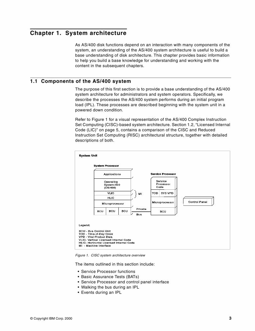
Refer to Figure 1 for a visual representation of the AS/400 Complex InstructionSet Computing (CISC)-based system architecture. Section 1.2, “Licensed InternalCode (LIC)” on page 5, contains a comparison of the CISC and ReducedInstruction Set Computing (RISC) architectural structure, together with detaileddescriptions of both.
Figure 1. CISC system architecture overview
The items outlined in this section include:
• Service Processor functions• Basic Assurance Tests (BATs)• Service Processor and control panel interface• Walking the bus during an IPL• Events during an IPL
© Copyright IBM Corp. 2000 3
Service processor functionsThe AS/400 system uses the service processor to get the system processor (alsoknown as the central processor unit or CPU) to an operational state. The CPUalso uses the service processor to provide error reporting and debug operationsfor the system CPU.
Some of the basic functions of the service processor are:
• Starts the system IPL
• Tests bus 0
• Tests the CPU
• Loads the CPU LIC
• Provides a system termination path (SRC display)
• Supports read and write time of day
• Supports read and write system Vital Product Data (VPD)
• Supports Programmed restart IPLs (that is, a PWRDWNSYS *IMMEDRESTART(*YES) command)
• Controls delayed power off
• Provides a general control panel interface
The following hardware is specifically service processor hardware (as comparedto system processor hardware):
• The time-of-day chip• The system Vital Product Data (VPD) storage• The Control panel interface
Basic Assurance Tests (BATs)During the IPL process, the service processor verifies that the I/O bus, the loadsource I/O bus unit, the system processor, and the service processor itself areoperational. It also supplies specific fault information to the user in the event of afailure during this verification process. These are known as Basic AssuranceTests (BATs).
Service processor and control panel interfaceThe control panel connects to the service processor and sets up an interface forthe user from which the IPL source can be selected and for indicating status anderror conditions. The control panel Licensed Internal Code gives the serviceprocessor and operating system access to control panel functions.
Walking the bus during IPLOn early 9406 systems (that is, the stage 1 model B), the service processor mustsearch multiple bus units on I/O bus 0. Bus 0 is the first I/O bus on these models.
This search consists of:
• A sequence of bus commands that first identifies the bus configuration,including location and state of each bus unit, and then checks each bus unit tofind the service processor load.
• An expected response from the bus unit identifying itself as the load sourceI/O bus unit.
4 AS/400 Disk Storage Topics and Tools
• Having located the load source I/O bus unit, the read-only storage (ROS)Licensed Internal Code loads the service processor random access memory(RAM) control storage with the service processor run-time code and turnscontrol over to that Licensed Internal Code.
On the next series of models manufactured after the model B, the serviceprocessor was designed to be part of a multiple function I/O bus unit. On thesemodels, the service processor is combined with disk, diskette, tape,communications, and on some models CD-ROM support. Searching for the loadsource I/O bus unit is quicker during IPL because bus 0 does not need to besearched to get the service processor code load. The IPL is performed from diskor tape devices attached directly to the system.
Events during IPLThe sequence of events that occur during an IPL from a powered-down conditionare outlined here:
1. When the system is first powered on, the service processor:
• Assumes control of bus 0 and obtains its Licensed Internal Codeload-source from disk or tape.
• Retrieves the Licensed Internal Code for the system processor.
2. The service processor sets up the interface between the operating system andcontrol panel functions.
3. Control storage is loaded with a sequence of BATs to check out the systemprocessor.
4. The system processor Vertical Licensed Internal Code (VLIC) is loaded intomain storage, followed by the Horizontal Licensed Internal Code (HLIC), whichis loaded into system processor control storage.
5. The system processor is started and, when the horizontal code is initialized,the service processor code instructs the system processor to start readingcontrol words out of control storage.
Once the Vertical Licensed Internal Code startup is complete, control of I/Obus 0 is transferred from the service processor to the system processor.
6. The system processor Vertical Licensed Internal Code continues loading codefrom the remaining I/O devices attached to the system.
7. Once the system is running, the user sign-on screen is displayed on thesystem console or attached and available workstations.
For more detailed descriptions of other components of the AS/400 system, suchas the various IOPs and IOAs related to storage, turn to Appendix A,“Architecture” on page 171.
1.2 Licensed Internal Code (LIC)
The AS/400 system product is made up of hardware and Licensed Internal Code(LIC). LIC supports the user interface (OS/400 instruction set, menus, help, listdisplays, a command set, and so forth). LIC is the group of instructions thatcontain basic machine control functions.
Chapter 1. System architecture 5
The first portion of LIC to be described is the Technology Independent MachineInterface (TIMI). Then, a detailed description of LIC is presented for both RISCand CISC systems.
1.2.1 Technology Independent Machine InterfaceThe AS/400 system is atypical in that it is defined by software, not by hardware.In other words, when a program presents instructions to the machine interface forexecution, it “thinks” that the interface is the AS/400 hardware. But it is not! Theinstructions presented to that interface pass through a layer of microcode beforethey can be understood by the hardware itself. Through a comprehensive layer ofmicrocode, TIMI design insulates application programs and users when hardwarecharacteristics change. When a different hardware technology is deployed, IBMrewrites sections of the microcode to absorb fluctuations in hardwarecharacteristics. As a result, the interface presented to the customer remains thesame.
This interface is known as the Technology Independent Machine Interface (TIMI).The microcode layer is known as the System Licensed Internal Code (SLIC).
The brilliance of this design was dramatically illustrated when the AS/400 systemchanged its processor technology from CISC processors to 64-bit RISCprocessors in 1995. With any other system, the move from CISC to RISC wouldinvolve recompiling (and possibly some rewriting) of programs. Even then, theprograms would run in 32-bit mode on the newer 64-bit hardware.
This was not so with the AS/400 system because of TIMI. Customers could saveprograms off their CISC AS/400 systems, restore them on their newer RISCAS/400 systems, and the programs would run. Not only did they run, but theybecame full function 64-bit programs.
As soon as they made the transition to RISC, customers had 64-bit applicationprograms that ran on a 64-bit operating system containing a 64-bit relationaldatabase that fully exploited the 64-bit RISC hardware. These same architecturalfeatures will be exploited to fully accommodate post-RISC technologies, whichmay have 96-bit or 128-bit processors.
RISC-based SLIC on PowerPC systems (V3R6, V3R7, V4Rn)Many of the frequently-executed routines that, on a non-AS/400 system typicallyreside in the operating system, have been moved to SLIC. As the various versionand release levels of OS/400 are released, more and more functions were movedinto SLIC. Because SLIC is closer to the silicon, routines placed in SLIC runfaster than routines placed “higher” in the machine. This provides an importantperformance gain, examples of which include some of the basic supervisoryfunctions. Examples of resource management functions that are in SLIC includevalidity and authorization checks.
Figure 2 shows how the structures compare between the CISC and RISCarchitectures.
6 AS/400 Disk Storage Topics and Tools
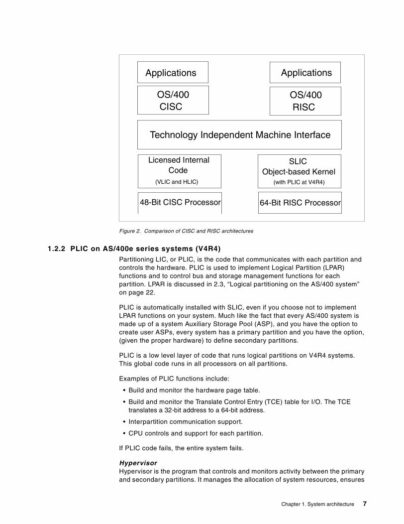
Figure 2. Comparison of CISC and RISC architectures
1.2.2 PLIC on AS/400e series systems (V4R4)Partitioning LIC, or PLIC, is the code that communicates with each partition andcontrols the hardware. PLIC is used to implement Logical Partition (LPAR)functions and to control bus and storage management functions for eachpartition. LPAR is discussed in 2.3, “Logical partitioning on the AS/400 system”on page 22.
PLIC is automatically installed with SLIC, even if you choose not to implementLPAR functions on your system. Much like the fact that every AS/400 system ismade up of a system Auxiliary Storage Pool (ASP), and you have the option tocreate user ASPs, every system has a primary partition and you have the option,(given the proper hardware) to define secondary partitions.
PLIC is a low level layer of code that runs logical partitions on V4R4 systems.This global code runs in all processors on all partitions.
Examples of PLIC functions include:
• Build and monitor the hardware page table.
• Build and monitor the Translate Control Entry (TCE) table for I/O. The TCEtranslates a 32-bit address to a 64-bit address.
• Interpartition communication support.
• CPU controls and support for each partition.
If PLIC code fails, the entire system fails.
HypervisorHypervisor is the program that controls and monitors activity between the primaryand secondary partitions. It manages the allocation of system resources, ensures
Applications Applications
OS/400CISC
OS/400RISC
Technology Independent Machine Interface
Licensed InternalCode
SLICObject-based Kernel
48-Bit CISC Processor 64-Bit RISC Processor
(VLIC and HLIC) (with PLIC at V4R4)
Chapter 1. System architecture 7
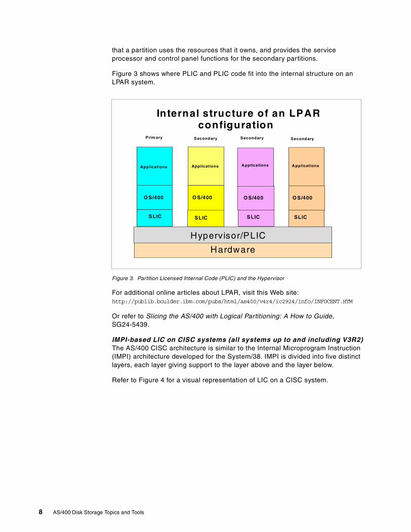
that a partition uses the resources that it owns, and provides the serviceprocessor and control panel functions for the secondary partitions.
Figure 3 shows where PLIC and PLIC code fit into the internal structure on anLPAR system.
Figure 3. Partition Licensed Internal Code (PLIC) and the Hypervisor
For additional online articles about LPAR, visit this Web site:http://publib.boulder.ibm.com/pubs/html/as400/v4r4/ic2924/info/INFOCENT.HTM
Or refer to Slicing the AS/400 with Logical Partitioning: A How to Guide,SG24-5439.
IMPI-based LIC on CISC systems (all systems up to and including V3R2)The AS/400 CISC architecture is similar to the Internal Microprogram Instruction(IMPI) architecture developed for the System/38. IMPI is divided into five distinctlayers, each layer giving support to the layer above and the layer below.
Refer to Figure 4 for a visual representation of LIC on a CISC system.
Internal structure of an LPARconfiguration
Hypervisor/PLIC
Hardware
O S/400 O S/400 O S/400O S/400
A pplications
SLICSLIC SLICSLIC
Applications A pplicationsApplications
Prim ary S econdary Secondary Secondary
8 AS/400 Disk Storage Topics and Tools
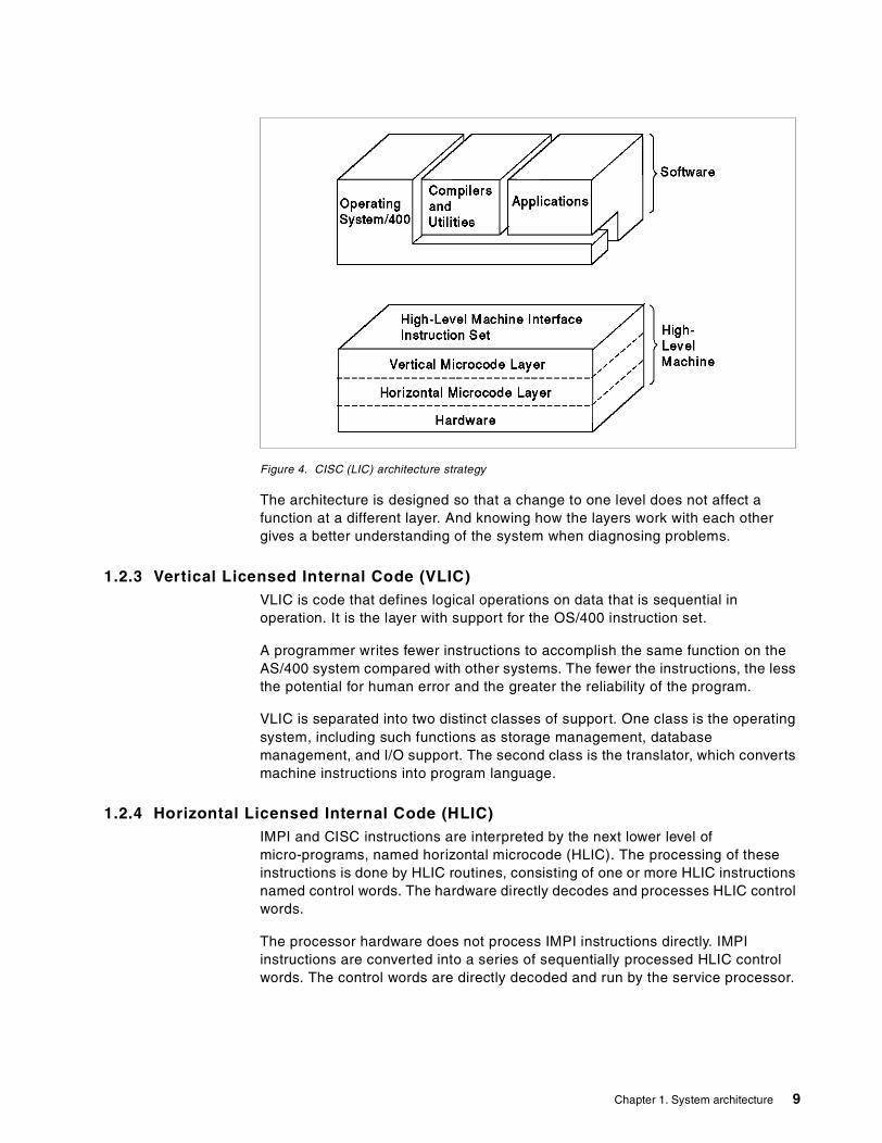
Figure 4. CISC (LIC) architecture strategy
The architecture is designed so that a change to one level does not affect afunction at a different layer. And knowing how the layers work with each othergives a better understanding of the system when diagnosing problems.
1.2.3 Vertical Licensed Internal Code (VLIC)VLIC is code that defines logical operations on data that is sequential inoperation. It is the layer with support for the OS/400 instruction set.
A programmer writes fewer instructions to accomplish the same function on theAS/400 system compared with other systems. The fewer the instructions, the lessthe potential for human error and the greater the reliability of the program.
VLIC is separated into two distinct classes of support. One class is the operatingsystem, including such functions as storage management, databasemanagement, and I/O support. The second class is the translator, which convertsmachine instructions into program language.
1.2.4 Horizontal Licensed Internal Code (HLIC)IMPI and CISC instructions are interpreted by the next lower level ofmicro-programs, named horizontal microcode (HLIC). The processing of theseinstructions is done by HLIC routines, consisting of one or more HLIC instructionsnamed control words. The hardware directly decodes and processes HLIC controlwords.
The processor hardware does not process IMPI instructions directly. IMPIinstructions are converted into a series of sequentially processed HLIC controlwords. The control words are directly decoded and run by the service processor.
Chapter 1. System architecture 9
1.3 AS/400 addressing
The system needs a method to identify a single destination for any informationtransfer. Every hardware component (bus, I/O processor, controller, and storageunit) has a unique address. The addressing convention is used to allow aspecified destination to read the data specified for the destination.
There are several addressing conventions used within AS/400 disk subsystems.Physical locations are used, as well as logical addresses, small computer systeminterface (SCSI) addressing, device function controller interface (DFCI)addressing, and direct select addressing (DSA).
DFCI and SCSI are further discussed in A.2.1, “Device Function ControllerInterface (DFCI) bus” on page 174, A.2.2, “Small Computer System Interface(SCSI) bus” on page 174, and A.5, “DASD I/O cables within the AS/400 system”on page 184. More information on DSA is available in 1.3.3, “Direct selectaddress (DSA) and unit address” on page 11.
IOPs are addressed in two modes:
Direct select addressing (DSA)The method for selecting a physical card slot during IPL or servicingwhen only a limited set of functions is allowed.
Logical bus unit addressingThe method for selecting an IOP during normal operation, after theIOP and its subsystem is identified and configured for the system. Thelogical address can differ from the direct select address, as discussedin the next topics.
Addressing in the AS/400 system has evolved dramatically from the CISCplatform to the RISC platform. Discussion of addressing begins with a descriptionof how the system addresses a component in a CISC system. As the topicprogresses, you can learn the addressing of components in the currenttechnology AS/400 systems.
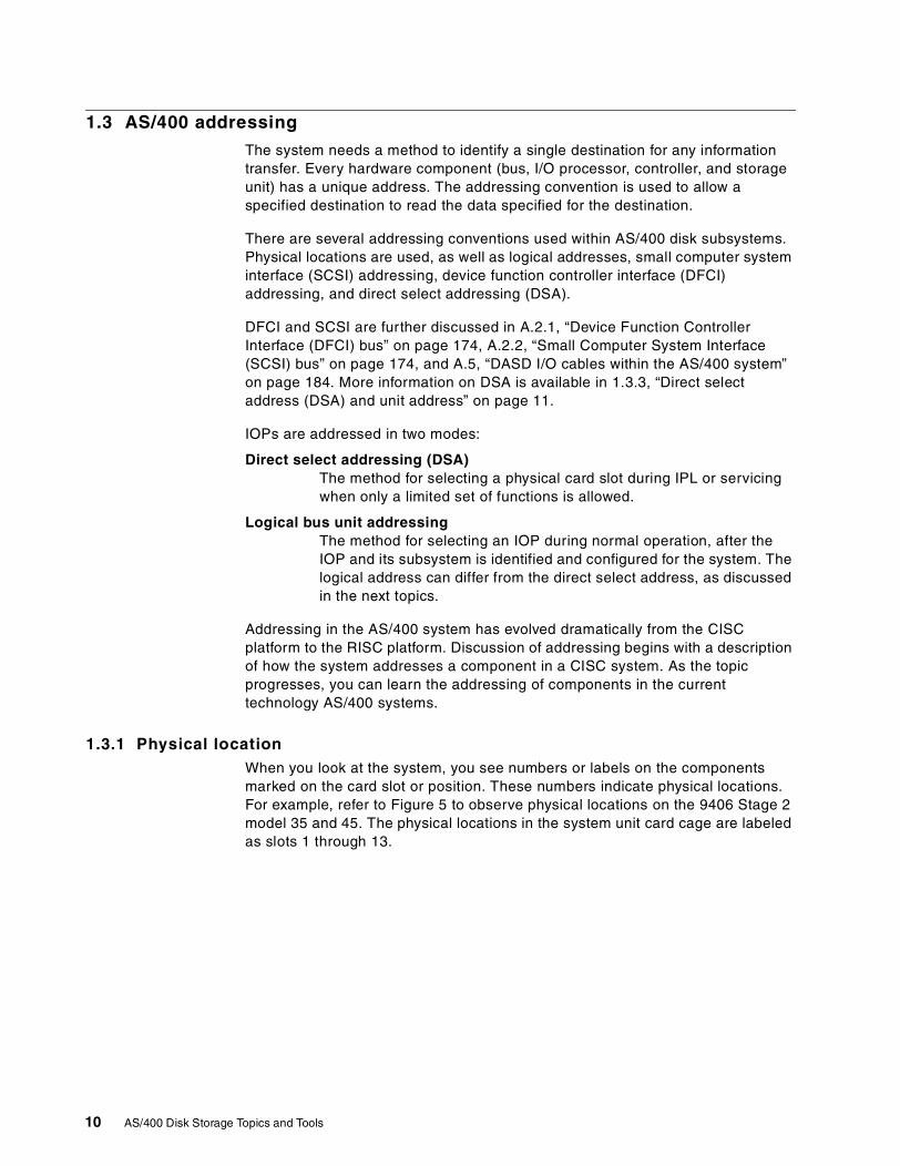
1.3.1 Physical locationWhen you look at the system, you see numbers or labels on the componentsmarked on the card slot or position. These numbers indicate physical locations.For example, refer to Figure 5 to observe physical locations on the 9406 Stage 2model 35 and 45. The physical locations in the system unit card cage are labeledas slots 1 through 13.
10 AS/400 Disk Storage Topics and Tools
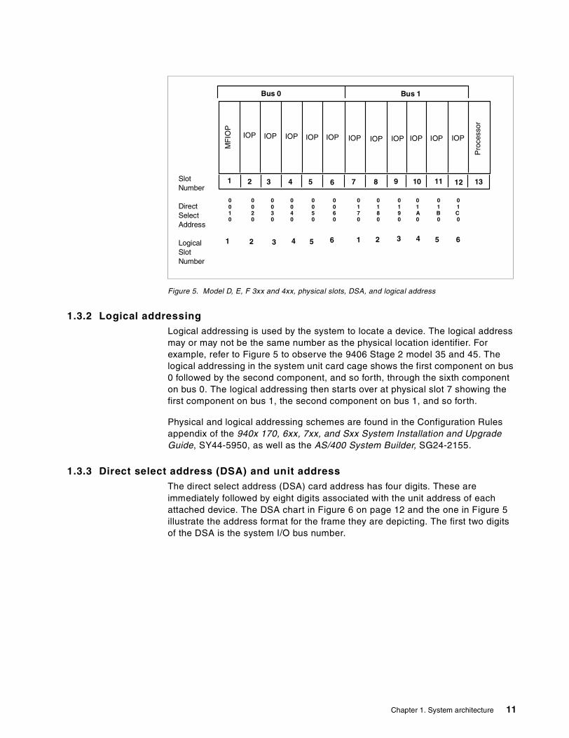
Figure 5. Model D, E, F 3xx and 4xx, physical slots, DSA, and logical address
1.3.2 Logical addressingLogical addressing is used by the system to locate a device. The logical addressmay or may not be the same number as the physical location identifier. Forexample, refer to Figure 5 to observe the 9406 Stage 2 model 35 and 45. Thelogical addressing in the system unit card cage shows the first component on bus0 followed by the second component, and so forth, through the sixth componenton bus 0. The logical addressing then starts over at physical slot 7 showing thefirst component on bus 1, the second component on bus 1, and so forth.
Physical and logical addressing schemes are found in the Configuration Rulesappendix of the 940x 170, 6xx, 7xx, and Sxx System Installation and UpgradeGuide, SY44-5950, as well as the AS/400 System Builder, SG24-2155.
1.3.3 Direct select address (DSA) and unit addressThe direct select address (DSA) card address has four digits. These areimmediately followed by eight digits associated with the unit address of eachattached device. The DSA chart in Figure 6 on page 12 and the one in Figure 5illustrate the address format for the frame they are depicting. The first two digitsof the DSA is the system I/O bus number.
Bus 0 Bus 1
0 0 0 0 0 0 0 0 0 0 0 00 0 0 0 0 0 1 1 1 1 1 11 2 3 4 5 6 7 8 9 A B C0 0 0 0 0 0 0 0 0 0 0 0
1 1312111098765432
3 65421654321
SlotNumber
DirectSelectAddress
LogicalSlotNumber
MF
IOP
Pro
cess
or
IOP IOP IOP IOP IOP IOP IOP IOP IOP IOP IOP
Chapter 1. System architecture 11
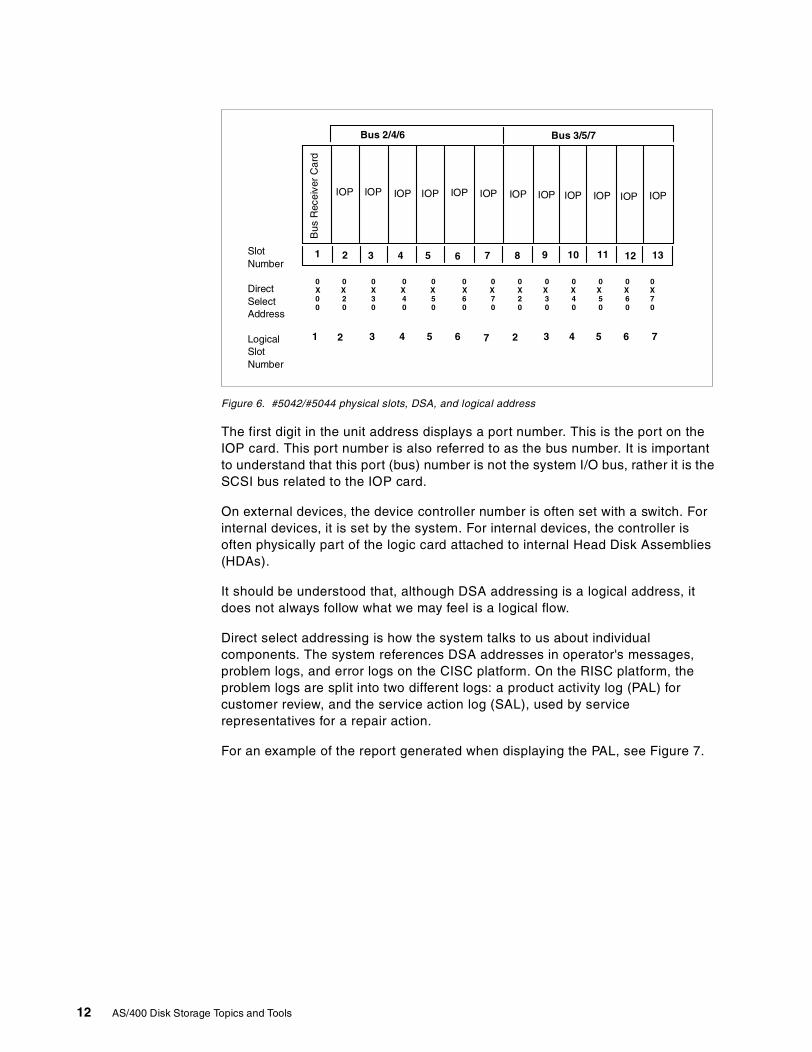
Figure 6. #5042/#5044 physical slots, DSA, and logical address
The first digit in the unit address displays a port number. This is the port on theIOP card. This port number is also referred to as the bus number. It is importantto understand that this port (bus) number is not the system I/O bus, rather it is theSCSI bus related to the IOP card.
On external devices, the device controller number is often set with a switch. Forinternal devices, it is set by the system. For internal devices, the controller isoften physically part of the logic card attached to internal Head Disk Assemblies(HDAs).
It should be understood that, although DSA addressing is a logical address, itdoes not always follow what we may feel is a logical flow.
Direct select addressing is how the system talks to us about individualcomponents. The system references DSA addresses in operator's messages,problem logs, and error logs on the CISC platform. On the RISC platform, theproblem logs are split into two different logs: a product activity log (PAL) forcustomer review, and the service action log (SAL), used by servicerepresentatives for a repair action.
For an example of the report generated when displaying the PAL, see Figure 7.
SlotNumber
DirectSelectAddress
LogicalSlotNumber
Bus 2/4/6 Bus 3/5/7
0 0 0 0 0 0 0 0 0 0 0 0 0X X X X X X X X X X X X X0 2 3 4 5 6 7 2 3 4 5 6 70 0 0 0 0 0 0 0 0 0 0 0 0
1 1312111098765432
3 65 7427654321
IOP IOP IOP IOP IOP IOP IOP IOP IOP IOP IOP IOP
Bus
Rec
eive
rC
ard
12 AS/400 Disk Storage Topics and Tools
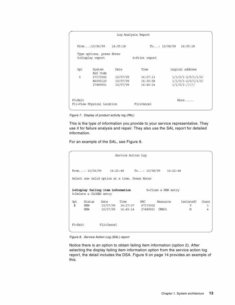
Figure 7. Display of product activity log (PAL)
This is the type of information you provide to your service representative. Theyuse it for failure analysis and repair. They also use the SAL report for detailedinformation.
For an example of the SAL, see Figure 8.
Figure 8. Service Action Log (SAL) report
Notice there is an option to obtain failing item information (option 2). Afterselecting the display failing item information option from the service action logreport, the detail includes the DSA. Figure 9 on page 14 provides an example ofthis.
Log Analysis Report
From...:10/06/99 14:05:18 To...: 10/08/99 14:05:18
Type options, press Enter5=Display report 6=Print report
Opt System Date Time Logical addressRef Code
5 67173002 10/07/99 16:27:13 1/1/0/1-2/0/1/1/0/B6005120 10/07/99 16:30:08 1/1/0/1-2/0/1/1/0/27489051 10/07/99 16:45:14 1/1/0/1-/////
F3=Exit More.....F11=View Physical Location F12+Cancel
Service Action Log
From...: 10/06/99 14:22:48 To...: 10/08/99 14:22:48
Select one valid option at a time, Press Enter
2=Display failing item information 8=Close a NEW entry9=Delete a CLOSED entry
Opt Status Date Time SRC Resource Isolated? Count2 NEW 10/07/99 16:27:07 67173002 Y 1
NEW 10/07/99 16:45:14 27489051 CMB01 N 4
F3=Exit F12=Cancel
Chapter 1. System architecture 13
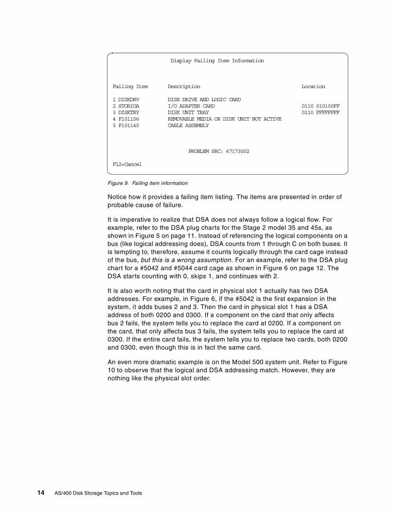
Figure 9. Failing item information
Notice how it provides a failing item listing. The items are presented in order ofprobable cause of failure.
It is imperative to realize that DSA does not always follow a logical flow. Forexample, refer to the DSA plug charts for the Stage 2 model 35 and 45s, asshown in Figure 5 on page 11. Instead of referencing the logical components on abus (like logical addressing does), DSA counts from 1 through C on both buses. Itis tempting to, therefore, assume it counts logically through the card cage insteadof the bus, but this is a wrong assumption. For an example, refer to the DSA plugchart for a #5042 and #5044 card cage as shown in Figure 6 on page 12. TheDSA starts counting with 0, skips 1, and continues with 2.
It is also worth noting that the card in physical slot 1 actually has two DSAaddresses. For example, in Figure 6, if the #5042 is the first expansion in thesystem, it adds buses 2 and 3. Then the card in physical slot 1 has a DSAaddress of both 0200 and 0300. If a component on the card that only affectsbus 2 fails, the system tells you to replace the card at 0200. If a component onthe card, that only affects bus 3 fails, the system tells you to replace the card at0300. If the entire card fails, the system tells you to replace two cards, both 0200and 0300, even though this is in fact the same card.
An even more dramatic example is on the Model 500 system unit. Refer to Figure10 to observe that the logical and DSA addressing match. However, they arenothing like the physical slot order.
Display Failing Item Information
Failing Item Description Location
1 DISKDRV DISK DRIVE AND LOGIC CARD2 STORIOA I/O ADAPTER CARD 0110 010100FF3 DISKTRY DISK UNIT TRAY 0110 FFFFFFFF4 F101106 REMOVABLE MEDIA OR DISK UNIT NOT ACTIVE5 F101140 CABLE ASSEMBLY
PROBLEM SRC: 67173002
F12=Cancel
14 AS/400 Disk Storage Topics and Tools
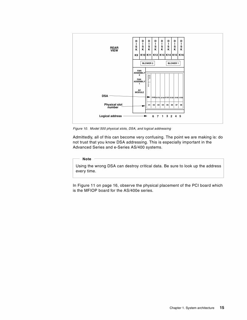
Figure 10. Model 500 physical slots, DSA, and logical addressing
Admittedly, all of this can become very confusing. The point we are making is: donot trust that you know DSA addressing. This is especially important in theAdvanced Series and e-Series AS/400 systems.
In Figure 11 on page 16, observe the physical placement of the PCI board whichis the MFIOP board for the AS/400e series.
REARVIEW
DISK
K16
DISK
K15
DISK
K14
DISK
K13
DISK
K12
DISK
K11
DISK
K10
DISK
K9
FANASSEMBLY
2
FANASSEMBLY
1
ACMODULE
REGULATOR
REG
1
0807060504030201
BLOWER 1BLOWER 2
Logical address
Physical slotnumber
DSA0160 01200170 0110 0130 01500140
21 3 4 56 7
Using the wrong DSA can destroy critical data. Be sure to look up the addressevery time.
Note
Chapter 1. System architecture 15
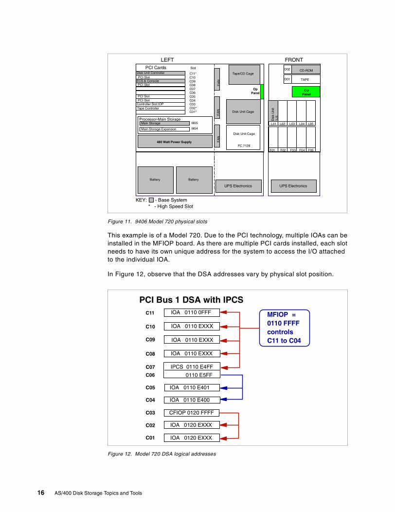
Figure 11. 9406 Model 720 physical slots
This example is of a Model 720. Due to the PCI technology, multiple IOAs can beinstalled in the MFIOP board. As there are multiple PCI cards installed, each slotneeds to have its own unique address for the system to access the I/O attachedto the individual IOA.
In Figure 12, observe that the DSA addresses vary by physical slot position.
Figure 12. Model 720 DSA logical addresses
FRONTLEFT
OpPanel
PCI Cards Slot
C11*C10C09C08C07C06C05C04C03C02*C01*
CD-ROM
L01 L02 L03 L04 L05
Dis
kU
nit
*LS
F01 F02 F03 F04 F05
TAPE
D02
D01
Disk Unit Cage
FC.7128
Disk Unit Cage
Tape/CD Cage
M05
M04
480 Watt Power Supply
UPS Electronics
Processor-Main Storage
OpPanel
FA
NF
AN
FA
N
Disk Unit Controller
ECS & Console
Main Storage
Battery Battery
UPS Electronics
KEY: - Base System* - High Speed Slot
PCI Slot
PCI Slot
Main Storage Expansion
Controller Slot IOPTape Controller
PCI SlotPCI Slot
PCI Bus 1 DSA with IPCSIOA 0110 0FFF
IOA 0110 EXXX
IOA 0110 E401
IOA 0110 E400
IOA 0120 EXXX
IOA 0120 EXXX
C11
C06 0110 E5FF
IOA 0110 EXXX
IPCS 0110 E4FF
C10
C09
C08
C07
C05
C04
C03
C02
C01
MFIOP =0110 FFFFcontrolsC11 to C04
CFIOP 0120 FFFF
IOA 0110 EXXX
16 AS/400 Disk Storage Topics and Tools
The first four digits represent the controller with which the IOA is associated. Theboard itself provides the first controller, and slots C04 through C11 are controlledby it. The second controller is installed in slot C03. This is an optional feature.When the second controller is installed, slots C01and C02 are controlled by it. Ifthe second controller in slot C03 remains empty, the last three slots on this boardare inactive.
The last four digits of the address on AS/400e series models vary, depending onthe type of card (for example whether it is a communication or workstationcontroller card). This addressing scheme is a unique characteristic to this familyof processors.
To properly manage and maintain the AS/400 system, it is important tounderstand the addressing characteristics for each component of the AS/400Advanced Series and e-series systems. Refer to your IBM ServiceRepresentative and the problem analysis and service information guideassociated with your system for more information. Schematics are also found inAS/400 System Builder, SG24-2155.
Note: The problem analysis guides vary by the associated system type. Thecorrect edition must be used to properly locate a component in an AS/400system.
For a more detailed discussion of the theory and the architecture of AS/400buses, IOPs, IOAs, and the various controller functions, refer to Appendix A,“Architecture” on page 171.
1.4 Summary
This chapter introduced you to the concepts of the AS/400 system architecture,beginning with identifying basic system unit components and walking through theflow of an IPL sequence. It provided an overview of differences in the manner inwhich the AS/400 system addresses and communicates with its devicecomponents in the CISC platform versus the RISC platform. There was also anoverview of the various levels of License Internal Code, including an introductionto the layer of code announced with V4R4 that aids in the implementation andmanagement of AS/400 logical partitions (LPAR).
Chapter 1. System architecture 17

18 AS/400 Disk Storage Topics and Tools
Chapter 2. Storage architecture
The purpose of this chapter is to provide information on the various optionsavailable for storage on the AS/400 system. While it primarily identifies anddescribes terminology for storage areas of a permanent nature, main storage isdiscussed as an option to provide a potential boost in overall systemperformance. Disk protection options are defined and discussed with examples inthis chapter. Chapter 3, “Storage options” on page 53, provides more detailedinformation about individual models of disk storage options.
Note: Refer to Appendix B, “Storage management terms used in SLIC” on page193, to understand the terminology related to disk storage.
2.1 Direct access storage device (DASD)
Direct access storage devices (another term for disk drives) are made up of flatcircular plates of metal, plastic, or glass, coated on both sides with magneticcompounds. Input signals, which can be audio, video, or data, are recorded onthe surface of a disk. These magnetic patterns or spots form concentric circulartracks which pass under a recording head when the disk is rotated by a drive unit.The disk platters are sealed against dust.
The DASD is used as a high-capacity storage device for AS/400 systems.
There is a wide selection of DASD available for the AS/400 system. Refer toChapter 3, “Storage options” on page 53, for a detailed discussion.
2.2 Cache
Cache is a supplemental memory system that temporarily stores frequently usedinstructions and data. Cache allows for quicker processing by the centralprocessor of a computer. The cache augments, and is an extension of, acomputer's main memory.
Both main memory and cache are internal, random access memory (RAM). Bothuse semiconductor-based transistor circuits.
2.2.1 Expert cacheExpert cache is a set of algorithms that execute in the main CPU. Expert cacheuses designated pools in main storage to cache database operations. The size ofthe pools is adjusted dynamically or controlled by the system operator as afunction of time. This allows the user to maximize the efficiency of the cache andmain storage usage, as workloads change over the course of a typical day.
The architecture of the AS/400 system allows for other types of devices to bedirect access storage devices. In this redbook, when the term direct accessstorage is used, it is meant to imply disk drives.
Note
© Copyright IBM Corp. 2000 19
Caching theory assumes that optimal caching occurs as close to the processor aspossible. By caching in main storage, the system not only eliminates accesses tothe storage devices, but all associated I/O traffic on the internal system buses aswell. In addition, an algorithm running in the main processor has a better view ofactual application trends and should do a better job, overall, of assessing whatdata should be cached.
Expert Cache works by minimizing the effect of synchronous DASD I/Os on a job.The best candidates for performance improvement are those jobs that are mostaffected by synchronous DASD I/Os. The ten jobs with the largest synchronousdisk I/O count per transaction are noted on the Job Statistics section of theTransaction Report. Other System, Component and Transaction reports availablewith the AS/400 Performance Tools/400 (5769-PT1) licensed program productalso identify disk I/O statistics. Refer to Performance Tools/400, SC41-4340, for adescription of each field and report relative to synchronous I/O.
Expert Cache provides a disk cache tuner option, which allows the AS/400system to take advantage of available main storage capacity. The tunerdynamically responds to system jobs to cache pages of data in main storage,thus reducing the time to process disk I/O.
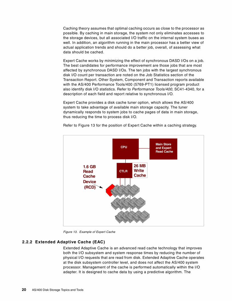
Refer to Figure 13 for the position of Expert Cache within a caching strategy.
Figure 13. Example of Expert Cache
2.2.2 Extended Adaptive Cache (EAC)Extended Adaptive Cache is an advanced read cache technology that improvesboth the I/O subsystem and system response times by reducing the number ofphysical I/O requests that are read from disk. Extended Adaptive Cache operatesat the disk subsystem controller level, and does not affect the AS/400 systemprocessor. Management of the cache is performed automatically within the I/Oadapter. It is designed to cache data by using a predictive algorithm. The
CPU
CTLR
26 MBWriteCache
Main Storeand ExpertRead Cache
1.6 GBReadCacheDevice(RCD)
20 AS/400 Disk Storage Topics and Tools
algorithm considers how recently and how frequently the host has accessed apredetermined range of data.
For additional detail regarding Extended Adaptive Cache, refer to Chapter 4,“Extended Adaptive Cache (EAC)” on page 57.
2.2.2.1 Read Cache Device (RCD)The Read Cache Device is a solid state 1.6 GB cache memory assembled in apackage. From the exterior, it resembles an AS/400 disk unit.
The RCD is optimized for use as cache memory on the AS/400 system. Instead ofa spinning platter inside, the RCD is packed with solid state memory chips thatfunction at electronic speeds.
It can be installed in a disk slot of the AS/400e server or expansion storageenclosure using disk concurrent maintenance, if the slot you install it in is vacant.Only one RCD can be installed per feature code #2748. If your system currentlyhas all DASD slots filled, plan for the removal both logically and physically of onedisk unit to accommodate the RCD. Once installed, the I/O adapter detects theRCD through automatic polling, and Extended Adaptive Cache goes to work.
The Read Cache Device helps reduce physical read requests to disk unitsattached to the same #2748 controller as the RCD.
The RCD can be used with RAID-5 protected storage devices or storagesubsystems with mirrored protection. The RCD itself does not require RAID-5 ormirrored protection because all data contained on the RCD is also on the disks.RCD storage is volatile. In the event of a RCD failure, read caching is suspendedand the system continues to run.
The Read Cache Device (RCD) is the memory for Extended Adaptive Cache.Purchase and install RCD for the Extended Adaptive Cache to function.
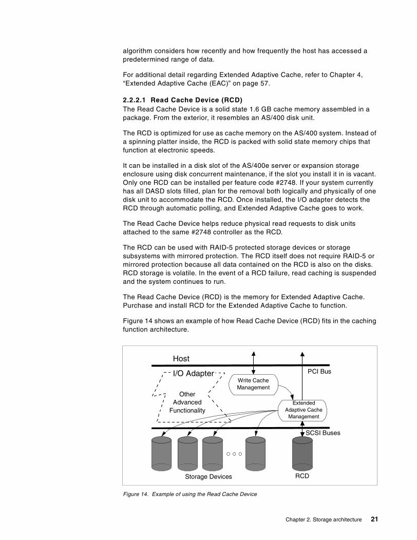
Figure 14 shows an example of how Read Cache Device (RCD) fits in the cachingfunction architecture.
Figure 14. Example of using the Read Cache Device
Host
I/O Adapter
SCSI Buses
PCI Bus
Storage Devices RCD
OtherAdvanced
Functionality
Write CacheManagement
ExtendedAdaptive Cache
Management
Chapter 2. Storage architecture 21

For additional detail regarding implementation of the Read Cache Device, seeChapter 4, “Extended Adaptive Cache (EAC)” on page 57.
For information regarding physical characteristics and proper physical placementof the RCD, refer to Chapter 3, “Storage options” on page 53.
2.3 Logical partitioning on the AS/400 system
Logical partitions (LPAR) enable multiple independent OS/400 instances orpartitions in an n-way symmetric multiprocessing AS/400e 7xx, 6xx and Sxx.Each partition requires its own processor(s), memory, disk(s), and systemconsole, with a CD-ROM and tape drive that can be allocated to each LPAR. WithLPAR, you can address multiple system requirements in a single, physicalmachine to achieve server consolidation, business unit consolidation, mixedproduction/test environments, integrated clusters, and more.
All V4R4 systems are installed with a primary partition with all resources initiallyallocated to it. Creating and managing secondary partitions is performed from theprimary partition. Movement of processors, memory, and interactive performancebetween partitions is achieved with an IPL of the affected partitions. Movement ofIOP resources between partitions does not require an IPL.
OS/400 is licensed once for the entire system by its usual processor group,regardless of the number of partitions. License management across partitions isnot supported. OS/400 V4R4 must be installed on each partition. Previousreleases are not supported on any logical partition.
For a visual representation of a Logical Partition configuration, representingpartition A and partition B, each with a console and assigned DASD, see Figure15.
Figure 15. Example LPAR configuration
Rely on this Web site for direction and management tips on Logical Partitioning:http://www.as400.ibm.com/lpar/
7304-way
2 GBmemory
A
2-way1 GB
B
2-way1 GB
22 AS/400 Disk Storage Topics and Tools
For additional online articles about LPAR, visit this Web site:http://publib.boulder.ibm.com/pubs/html/as400/v4r4/ic2924/info/INFOCENT.HTM
2.4 Data storage and management on the AS/400 system
Information is a company asset. Computer systems are based on information,otherwise known as data. Business decisions are made every day based on thecontent of stored information. Business growth depends upon efficient access toand storage of its information resource.
Data is stored in objects on the AS/400 system, the object providing a template todescribe and access the information. The AS/400 database consists of fileobjects whose associated data is stored permanently in the system. Each filetype has unique characteristics that determine how the file is used and whatcapabilities it provides.
The Integrated File System provides structure for all information stored on theAS/400 system. As a part of the operating system, it supports stream files so thatinput, output, and storage management of Integrated File System objects issimilar to personal computer or UNIX operating systems. The Integrated FileSystem is discussed in 2.5, “Integrated File System” on page 24.
The Database and File Systems category of the Information Center contains avariety of topics about storing data on your AS/400 system. Other such topicsinclude managing data, files, libraries, and databases, and managing andaccessing data in the DB2 Universal Database (UDB) for AS/400. To view theInformation Center, refer to:http://publib.boulder.ibm.com/pubs/html/as400/v4r4/ic2924/info/INFOCENT.HTM
2.4.1 Data managementData management is the part of the operating system that controls the storingand accessing of data by an application program. The data may be on internalstorage (for example, a database file), on external media (diskette, tape, printerfile objects), or on another AS/400 system.
The Data Management topic of the Information Center describes the datamanagement functions that your application uses in creating and accessing dataon the AS/400 system and in ensuring the integrity of the data.
2.4.2 Database managementDB2 Universal Database for AS/400 is the integrated relational databasemanager on your AS/400 system. As well as providing access to and protectionfor your data, DB2 UDB for AS/400 provides advanced functions such asreferential integrity and parallel database processing.
The Database Management topic of the Information Center describes how to takeadvantage of DB2 UDB for AS/400 to access and manage AS/400 data throughan application or a user interface.
For detailed information on these subjects refer to the AS/400 Information Center,SK3T-2027 (CD version which comes with your AS/400 system). This packagealso contains your AS/400 Softcopy Library. Or you can visit the Information
Chapter 2. Storage architecture 23
Center Web site at: http://www.as400.ibm.com/infocenter orhttp://publib.boulder.ibm.com/pubs/html/as400/v4r4/ic2924/info/INFOCENT.HTM
2.5 Integrated File System
As previously mentioned, the Integrated File System is a part of OS/400 that letsyou support stream input, output, and storage management similar to personalcomputer and UNIX operating systems, while providing structure for allinformation stored in the AS/400 system. The key features of the Integrated FileSystem are:
• Support for storing information in stream files that can contain long continuousstrings of data
• A hierarchical directory structure
• A common interface that allows users and applications to access not only thestream files, but also database files, documents, and other objects that arestored in the AS/400 system
• A common view of stream files that are stored locally on the AS/400, anIntegrated Netfinity Server for AS/400, or a remote Windows NT server.
Two file systems providing flexible storage management are UDFS andQFILESVR. For a description of the User Defined File System (UDFS), refer toChapter 5, “Extending the Integrated File System with UDFS” on page 73, andChapter 6, “Using the QFILESVR.400 file system” on page 81, for the OS/400File Server file system.
For additional reading on using the Integrated File System on the AS/400 system,refer to Integrated File System Introduction, SC41-5711.
2.6 Digital Versatile Disk (DVD) on the AS/400 system
DVD is a family of optical discs that have the same overall dimensions as a CD,with significantly higher capacities. DVD is a writable media, where CD-ROM isread-only. DVDs are double-sided, where CDs are single-sided. Dual-layer DVDversions are planned. DVD drives read most CD media, and other pre-recordedDVD media (DVD-Video and DVD-ROM).
DVD technology is becoming as important for the computer world as for the videoworld. DVD originally stood for Digital VideoDisc. The “video” was dropped, and itbecame simply DVD. It is now dubbed Digital Versatile Disk, which is the nameendorsed by the DVD Forum.
2.6.1 How DVD applies to the AS/400 systemDVD will be offered as an alternative to internal magnetic tape devices. It will beoffered as the primary save and restore and software distribution device on selectAS/400 systems. DVD is not intended to be a full tape replacement, but isintended to provide those AS/400 customers, who do not need tape, a lower-costremovable media alternative.
Watch for more information on DVD on the AS/400 system in future releases. Forphysical characteristics of DVD, see Chapter 3, “Storage options” on page 53.
24 AS/400 Disk Storage Topics and Tools
2.7 Storage Area Network (SAN)
Storage Area Network (SAN) is a high-speed network that allows theestablishment of direct connections between storage devices and processors. Itcan be compared to a local area network (LAN), providing the same function withdifferent technology.
Note: In the AS/400 environment, SAN has also been referred to as System AreaNetwork.
The information needs of business can grow quickly. An IBM SAN solution canhelp keep the information available as growth is incorporated.
IBM plans to deliver our SAN strategy in phases. This will help to leverage newtechnologies as they mature, and to help businesses seamlessly integrate SANtechnology into their computing system infrastructure, while leveraginginvestments in storage, server, and application resources.
As SAN is evolving, IBM SAN technology is evolving in three phases:
• SAN-attached storage, leveraging the any-to-any hub connectivity of SANtechnology
• SAN optimized storage exploiting SAN characteristics and delivering earlySAN solutions
• SAN optimized systems leveraging the mature technology and delivering onthe SAN promise of system-wide solutions
For an introduction to SAN, refer to the redbook Introduction to Storage AreaNetwork, SAN, SG24-5470.
For additional information on SAN, refer to the following Web site:http://www.storage.ibm.com/ibmsan/index.htm
Refer to the following Web site for a white paper to explore how deploying an IBMenterprise Storage Area Network (SAN) can help make the corporate informationutility a reality: http://www.storage.ibm.com/ibmsan/whitepaper/strategy.htm
2.8 IBM Versatile Storage Server (VSS)
The IBM 2105 Versatile Storage Server (VSS) is designed to provide a flexibleapproach to storage centralization in support of server consolidation. By usingthe IBM 7133 Serial Disk Subsystem as its storage building block, VersatileStorage Server provides investment protection. With the IBM Versatile StorageServer, disk storage can be consolidated into a single, powerful system thatoffers many levels of advanced function. Examples include remote Web-basedmanagement, data sharing for like servers, and dynamic capacity allocation.
The highlights include:
• High-performance serial disk• High-availability storage with RAID protection• Flexible Web-based management with StorWatch Versatile Storage Specialist• Exceptional scalability from 200 GB to 4.1 TB usable capacity
Chapter 2. Storage architecture 25
See Chapter 3, “Storage options” on page 53, for additional physicalcharacteristics and IOP requirements for the VSS Storage option for the AS/400system.
2.9 IBM Enterprise Storage Server (ESS)
The Enterprise Storage Server (ESS) offers high performance, attachmentflexibility, and large capacity. Data from different platforms can be stored within asingle high performance, high availability storage server. Storage consolidationcan be the first step towards server consolidation, reducing the number of boxesyou have to manage and allowing the flexibility to add or assign capacity whenand where it is needed.
Note: The ESS is also a 2105, with different model numbers than the VSS.
ESS supports all the major server platforms: S/390, AS/400, Windows NT, andmany flavors of UNIX. With a capacity of up to 11 TB, and up to 32 hostconnections, an ESS can meet both your high capacity requirements and yourperformance expectations. The maximum addressable storage varies by AS/400model, up to 4.2 TB on a fully populated AS/400e server 740. Refer to theSummary sections of the AS/400e System Handbook, GA19-5486, to identify themaximum disk storage allowed by system model.
The enclosure of the Enterprise Storage Server incorporates dual RISC 4-waySymmetrical Multiprocessor (SMP) processors. Sixteen standard configurationsrange from 400 GB to over 11 TB. Each standard configuration provides asupport infrastructure base of 6 GB cache, 384 MB nonvolatile storage (NVS),four device adapter pairs, and 9 GB, 18 GB, or 36 GB serial disks in a serial loopconfiguration. The ESS provides RAID-5 protection.
Enterprise Storage Servers support all platforms supported by the VersatileStorage Server, including RS/6000 running AIX and many leading UNIX variants,Netfinity, and other PC servers running Windows NT or Novell Netware, andCompaq AlphaServers running OpenVMS. In addition, the ESS supportsSystem/390 servers running OS/390 code, VM, VSE, and TPF. Storage capacityis partitioned among the attached servers using the Web-based StorWatch ESSSpecialist management tool.
See Chapter 3, “Storage options” on page 53, for additional physicalcharacteristics and IOP requirements for the ESS storage option in the AS/400system.
2.10 AS/400 DASD availability options
In today's environment, availability of the information system is a critical part of acompany's needs. In this environment, it is critical for IT specialists to be skilled inunderstanding and developing plans to enable high availability. This sectionpresents the concepts and procedures that maximize the availability of thesystem from a DASD perspective, with information on a variety of availabilityoptions.
The topics in this section provide an overview of ASP and single level storageprotection options available for your DASD. This section covers topics involving
26 AS/400 Disk Storage Topics and Tools
DASD management, including mirroring, check summing, data parity protection,integrated hardware disk compression, Auxiliary Storage Pool (ASP), andHierarchical Storage Management (HSM). In order for you to understand andimplement the following availability concepts, it is imperative that you read theAS/400 Backup Recovery Guide, SC41-5304. Be sure to use the correct versionand release level of documentation for your system when planning your DASDconfiguration and protection.
2.10.1 Mirrored protectionMirrored protection is a function that increases the availability of the AS/400system in the event of a failure of a disk-related hardware component (such asthe bus, IOP, controller, or disk unit). It can be implemented on all models of theAS/400 system as it is part of the Licensed Internal Code.
Different levels of mirrored protection are possible, depending on what hardwareis duplicated—bus, IOP, controller or disk unit. Mirroring allows the system toremain available during a failure of a disk-related hardware component, if thefailing hardware component (and hardware components attached to it) areduplicated. For some system units, the failed hardware components can beserviced while the system remains available.
2.10.1.1 DASD mirroring within an ASPPrior to OS/400 V3R7, there were four levels of mirrored protection offered for theCISC platform as well as in RISC.
A level of mirroring known as power domain mirroring occurs when the DASDIOPs and the buses they are attached to are isolated to different power sources,as in racks (for “white box” models) or towers (for the AS/400 Advanced Seriesmodels). With power domain mirroring, one rack or tower could lose power andall data would still be available to the users and the system would continue tooperate. This level of mirrored protection is viewed as bus-level protection ondisk protection screens visible through the use of DST or SST menu options.
Refer to Figure 16 on page 28 to observe the structure of each level of mirroring:device, controller, IOP, and bus.
Chapter 2. Storage architecture 27
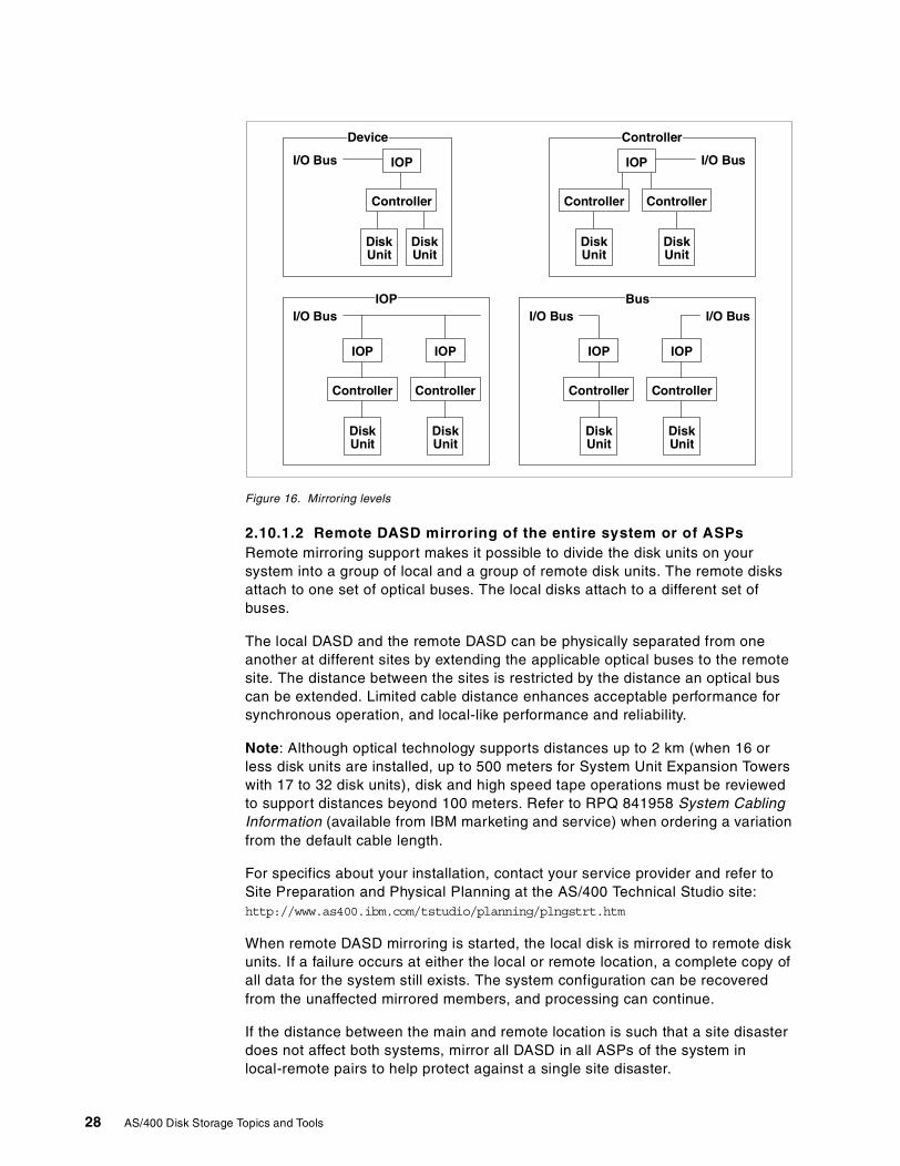
Figure 16. Mirroring levels
2.10.1.2 Remote DASD mirroring of the entire system or of ASPsRemote mirroring support makes it possible to divide the disk units on yoursystem into a group of local and a group of remote disk units. The remote disksattach to one set of optical buses. The local disks attach to a different set ofbuses.
The local DASD and the remote DASD can be physically separated from oneanother at different sites by extending the applicable optical buses to the remotesite. The distance between the sites is restricted by the distance an optical buscan be extended. Limited cable distance enhances acceptable performance forsynchronous operation, and local-like performance and reliability.
Note: Although optical technology supports distances up to 2 km (when 16 orless disk units are installed, up to 500 meters for System Unit Expansion Towerswith 17 to 32 disk units), disk and high speed tape operations must be reviewedto support distances beyond 100 meters. Refer to RPQ 841958 System CablingInformation (available from IBM marketing and service) when ordering a variationfrom the default cable length.
For specifics about your installation, contact your service provider and refer toSite Preparation and Physical Planning at the AS/400 Technical Studio site:http://www.as400.ibm.com/tstudio/planning/plngstrt.htm
When remote DASD mirroring is started, the local disk is mirrored to remote diskunits. If a failure occurs at either the local or remote location, a complete copy ofall data for the system still exists. The system configuration can be recoveredfrom the unaffected mirrored members, and processing can continue.
If the distance between the main and remote location is such that a site disasterdoes not affect both systems, mirror all DASD in all ASPs of the system inlocal-remote pairs to help protect against a single site disaster.
I/O Bus
Controller
DiskUnit
DiskUnit
IOP I/O Bus
Controller
DiskUnit
DiskUnit
IOP
Controller
I/O Bus
DiskUnit
IOP
Controller
DiskUnit
IOP
Controller
I/O Bus
DiskUnit
IOP
Controller
DiskUnit
IOP
Controller
I/O Bus
ControllerDevice
BusIOP
28 AS/400 Disk Storage Topics and Tools
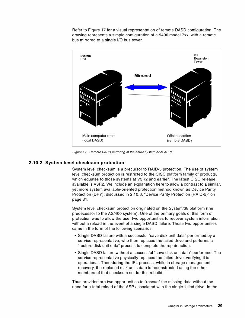
Refer to Figure 17 for a visual representation of remote DASD configuration. Thedrawing represents a simple configuration of a 9406 model 7xx, with a remotebus mirrored to a single I/O bus tower.
Figure 17. Remote DASD mirroring of the entire system or of ASPs
2.10.2 System level checksum protectionSystem level checksum is a precursor to RAID-5 protection. The use of systemlevel checksum protection is restricted to the CISC platform family of products,which equates to those systems at V3R2 and earlier. The latest CISC releaseavailable is V3R2. We include an explanation here to allow a contrast to a similar,yet more system available-oriented protection method known as Device ParityProtection (DPY), discussed in 2.10.3, “Device Parity Protection (RAID-5)” onpage 31.
System level checksum protection originated on the System/38 platform (thepredecessor to the AS/400 system). One of the primary goals of this form ofprotection was to allow the user two opportunities to recover system informationwithout a reload in the event of a single DASD failure. Those two opportunitiescame in the form of the following scenarios:
• Single DASD failure with a successful “save disk unit data” performed by aservice representative, who then replaces the failed drive and performs a“restore disk unit data” process to complete the repair action.
• Single DASD failure without a successful “save disk unit data” performed. Theservice representative physically replaces the failed drive, verifying it isoperational. Then during the IPL process, while in storage managementrecovery, the replaced disk units data is reconstructed using the othermembers of that checksum set for this rebuild.
Thus provided are two opportunities to “rescue” the missing data without theneed for a total reload of the ASP associated with the single failed drive. In the
Mirrored
I/OExpansionTower
SystemUnit
Main computer room(local DASD)
Offsite location(remote DASD)
Chapter 2. Storage architecture 29
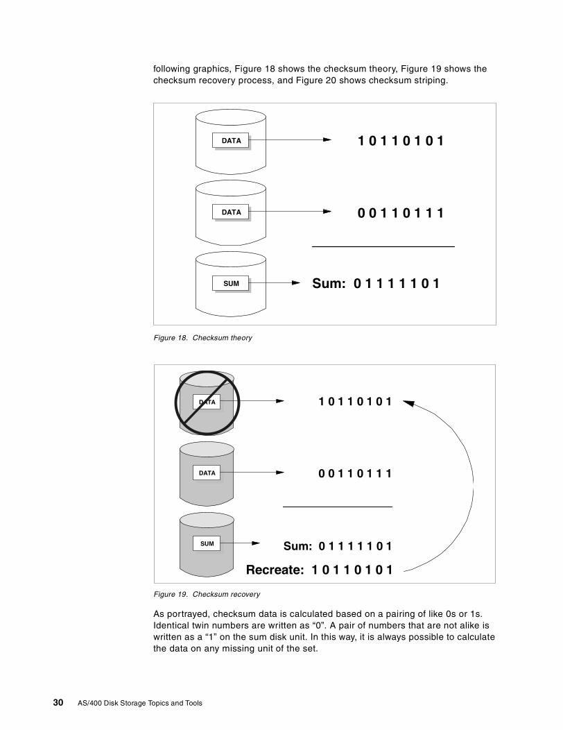
following graphics, Figure 18 shows the checksum theory, Figure 19 shows thechecksum recovery process, and Figure 20 shows checksum striping.
Figure 18. Checksum theory
Figure 19. Checksum recovery
As portrayed, checksum data is calculated based on a pairing of like 0s or 1s.Identical twin numbers are written as “0”. A pair of numbers that are not alike iswritten as a “1” on the sum disk unit. In this way, it is always possible to calculatethe data on any missing unit of the set.
DATA
DATA
1 0 1 1 0 1 0 1
0 0 1 1 0 1 1 1
Sum: 0 1 1 1 1 1 0 1SUM
Recreate: 1 0 1 1 0 1 0 1
DATA
DATA
1 0 1 1 0 1 0 1
0 0 1 1 0 1 1 1
Sum: 0 1 1 1 1 1 0 1SUM
30 AS/400 Disk Storage Topics and Tools
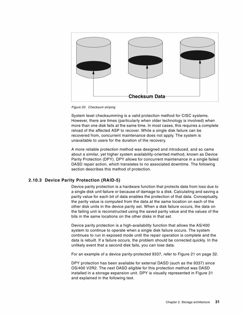
Figure 20. Checksum striping
System level checksumming is a valid protection method for CISC systems.However, there are times (particularly when older technology is involved) whenmore than one disk fails at the same time. In most cases, this requires a completereload of the affected ASP to recover. While a single disk failure can berecovered from, concurrent maintenance does not apply. The system isunavailable to users for the duration of the recovery.
A more reliable protection method was designed and introduced, and so cameabout a similar, yet higher system availability-oriented method, known as DeviceParity Protection (DPY). DPY allows for concurrent maintenance in a single failedDASD repair action, which translates to no associated downtime. The followingsection describes this method of protection.
2.10.3 Device Parity Protection (RAID-5)Device parity protection is a hardware function that protects data from loss due toa single disk unit failure or because of damage to a disk. Calculating and saving aparity value for each bit of data enables the protection of that data. Conceptually,the parity value is computed from the data at the same location on each of theother disk units in the device parity set. When a disk failure occurs, the data onthe failing unit is reconstructed using the saved parity value and the values of thebits in the same locations on the other disks in that set.
Device parity protection is a high-availability function that allows the AS/400system to continue to operate when a single disk failure occurs. The systemcontinues to run in exposed mode until the repair operation is complete and thedata is rebuilt. If a failure occurs, the problem should be corrected quickly. In theunlikely event that a second disk fails, you can lose data.
For an example of a device parity-protected 9337, refer to Figure 21 on page 32.
DPY protection has been available for external DASD (such as the 9337) sinceOS/400 V2R2. The next DASD eligible for this protection method was DASDinstalled in a storage expansion unit. DPY is visually represented in Figure 21and explained in the following text.
Checksum Data
Chapter 2. Storage architecture 31
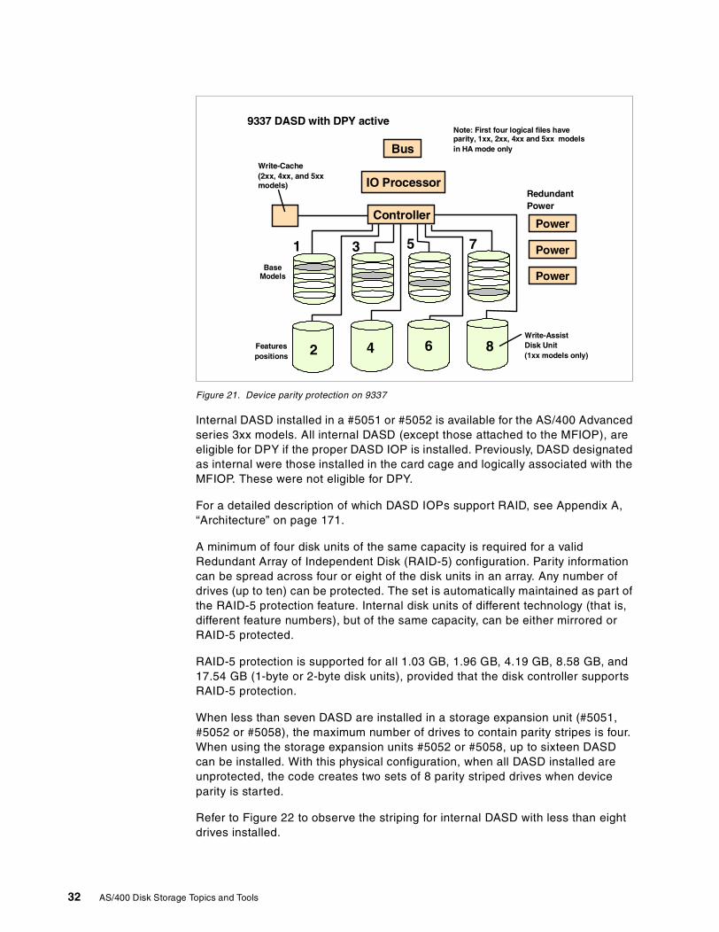
Figure 21. Device parity protection on 9337
Internal DASD installed in a #5051 or #5052 is available for the AS/400 Advancedseries 3xx models. All internal DASD (except those attached to the MFIOP), areeligible for DPY if the proper DASD IOP is installed. Previously, DASD designatedas internal were those installed in the card cage and logically associated with theMFIOP. These were not eligible for DPY.
For a detailed description of which DASD IOPs support RAID, see Appendix A,“Architecture” on page 171.
A minimum of four disk units of the same capacity is required for a validRedundant Array of Independent Disk (RAID-5) configuration. Parity informationcan be spread across four or eight of the disk units in an array. Any number ofdrives (up to ten) can be protected. The set is automatically maintained as part ofthe RAID-5 protection feature. Internal disk units of different technology (that is,different feature numbers), but of the same capacity, can be either mirrored orRAID-5 protected.
RAID-5 protection is supported for all 1.03 GB, 1.96 GB, 4.19 GB, 8.58 GB, and17.54 GB (1-byte or 2-byte disk units), provided that the disk controller supportsRAID-5 protection.
When less than seven DASD are installed in a storage expansion unit (#5051,#5052 or #5058), the maximum number of drives to contain parity stripes is four.When using the storage expansion units #5052 or #5058, up to sixteen DASDcan be installed. With this physical configuration, when all DASD installed areunprotected, the code creates two sets of 8 parity striped drives when deviceparity is started.
Refer to Figure 22 to observe the striping for internal DASD with less than eightdrives installed.
9337 DASD with DPY active
Power
Power
Power
Write-Cache(2xx, 4xx, and 5xxmodels)
Note: First four logical files haveparity, 1xx, 2xx, 4xx and 5xx modelsin HA mode only
RedundantPower
Write-AssistDisk Unit(1xx models only)
Featurespositions
BaseModels
Bus
IO Processor
Controller
1 3 5 7
2 4 6 8
32 AS/400 Disk Storage Topics and Tools
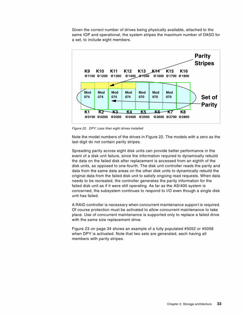
Given the correct number of drives being physically available, attached to thesame IOP and operational, the system stripes the maximum number of DASD fora set, to include eight members.
Figure 22. DPY: Less than eight drives installed
Note the model numbers of the drives in Figure 22. The models with a zero as thelast digit do not contain parity stripes.
Spreading parity across eight disk units can provide better performance in theevent of a disk unit failure, since the information required to dynamically rebuildthe data on the failed disk after replacement is accessed from an eighth of thedisk units, as opposed to one-fourth. The disk unit controller reads the parity anddata from the same data areas on the other disk units to dynamically rebuild theoriginal data from the failed disk unit to satisfy ongoing read requests. When dataneeds to be recreated, the controller generates the parity information for thefailed disk unit as if it were still operating. As far as the AS/400 system isconcerned, the subsystem continues to respond to I/O even though a single diskunit has failed.
A RAID controller is necessary when concurrent maintenance support is required.Of course protection must be activated to allow concurrent maintenance to takeplace. Use of concurrent maintenance is supported only to replace a failed drivewith the same size replacement drive.
Figure 23 on page 34 shows an example of a fully populated #5052 or #5058when DPY is activated. Note that two sets are generated, each having allmembers with parity stripes.
K1 K2 K3 K4 K5 K6 K7 K8@0100 @0200 @0300 @0400 @2500 @2600 @2700 @2800
K9 K10 K11 K12 K13 K14 K15 K16@1100 @1200 @1300 @1400 @1500 @1600 @1700 @1800
Mod074
Mod070 Set of
Parity
Mod074
Mod074
Mod074
Mod070
Mod070
ParityStripes
Chapter 2. Storage architecture 33
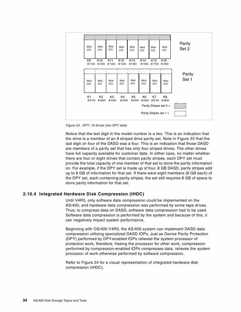
Figure 23. DPY: 16 drives (two DPY sets)
Notice that the last digit in the model number is a two. This is an indication thatthe drive is a member of an 8 striped drive parity set. Note in Figure 22 that thelast digit on four of the DASD was a four. This is an indication that those DASDare members of a parity set that has only four striped drives. The other driveshave full capacity available for customer data. In either case, no matter whetherthere are four or eight drives that contain parity stripes, each DPY set mustprovide the total capacity of one member of that set to store the parity informationon. For example, if the DPY set is made up of four, 8 GB DASD, parity stripes addup to 8 GB of information for that set. If there were eight members (8 GB each) ofthe DPY set, each containing parity stripes, the set still requires 8 GB of space tostore parity information for that set.
2.10.4 Integrated Hardware Disk Compression (IHDC)Until V4R3, only software data compression could be implemented on theAS/400, and hardware data compression was performed by some tape drives.Thus, to compress data on DASD, software data compression had to be used.Software data compression is performed by the system and because of this, itcan negatively impact system performance.
Beginning with OS/400 V4R3, the AS/400 system can implement DASD datacompression utilizing specialized DASD IOPs. Just as Device Parity Protection(DPY) performed by DPY-enabled IOPs relieved the system processor ofprotection work, therefore, freeing the processor for other work, compressionperformed by compression-enabled IOPs compresses data, relieves the systemprocessor of work otherwise performed by software compression.
Refer to Figure 24 for a visual representation of integrated hardware diskcompression (IHDC).
K1 K2 K3 K4 K5 K6 K7 K8@0100 @0200 @0300 @0400 @2500 @2600 @2700 @2800
K9 K10 K11 K12 K13 K14 K15 K16@1100 @1200 @1300 @1400 @1500 @1600 @1700 @1800
Mod072
Mod072
Mod072
ParitySet 2
Mod072
Mod072
Mod072
Mod072
Mod072
Parity Stripes set 1 =
Mod072
Mod072
Mod072
Mod072
Mod072
Mod072
Mod072
Mod072
ParitySet 1
Parity Stripes set 2 =
34 AS/400 Disk Storage Topics and Tools
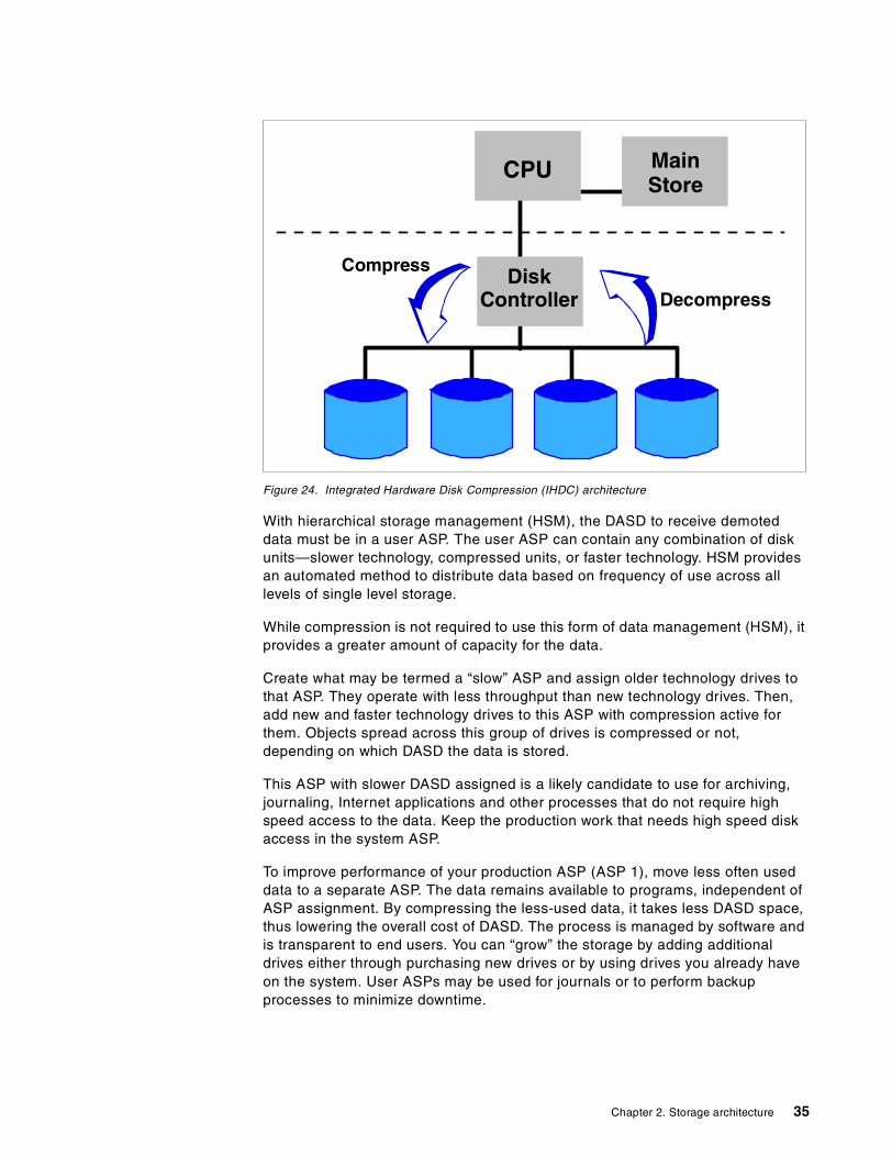
Figure 24. Integrated Hardware Disk Compression (IHDC) architecture
With hierarchical storage management (HSM), the DASD to receive demoteddata must be in a user ASP. The user ASP can contain any combination of diskunits—slower technology, compressed units, or faster technology. HSM providesan automated method to distribute data based on frequency of use across alllevels of single level storage.
While compression is not required to use this form of data management (HSM), itprovides a greater amount of capacity for the data.
Create what may be termed a “slow” ASP and assign older technology drives tothat ASP. They operate with less throughput than new technology drives. Then,add new and faster technology drives to this ASP with compression active forthem. Objects spread across this group of drives is compressed or not,depending on which DASD the data is stored.
This ASP with slower DASD assigned is a likely candidate to use for archiving,journaling, Internet applications and other processes that do not require highspeed access to the data. Keep the production work that needs high speed diskaccess in the system ASP.
To improve performance of your production ASP (ASP 1), move less often useddata to a separate ASP. The data remains available to programs, independent ofASP assignment. By compressing the less-used data, it takes less DASD space,thus lowering the overall cost of DASD. The process is managed by software andis transparent to end users. You can “grow” the storage by adding additionaldrives either through purchasing new drives or by using drives you already haveon the system. User ASPs may be used for journals or to perform backupprocesses to minimize downtime.
MainStore
CPU
DiskController Decompress
Compress
Chapter 2. Storage architecture 35
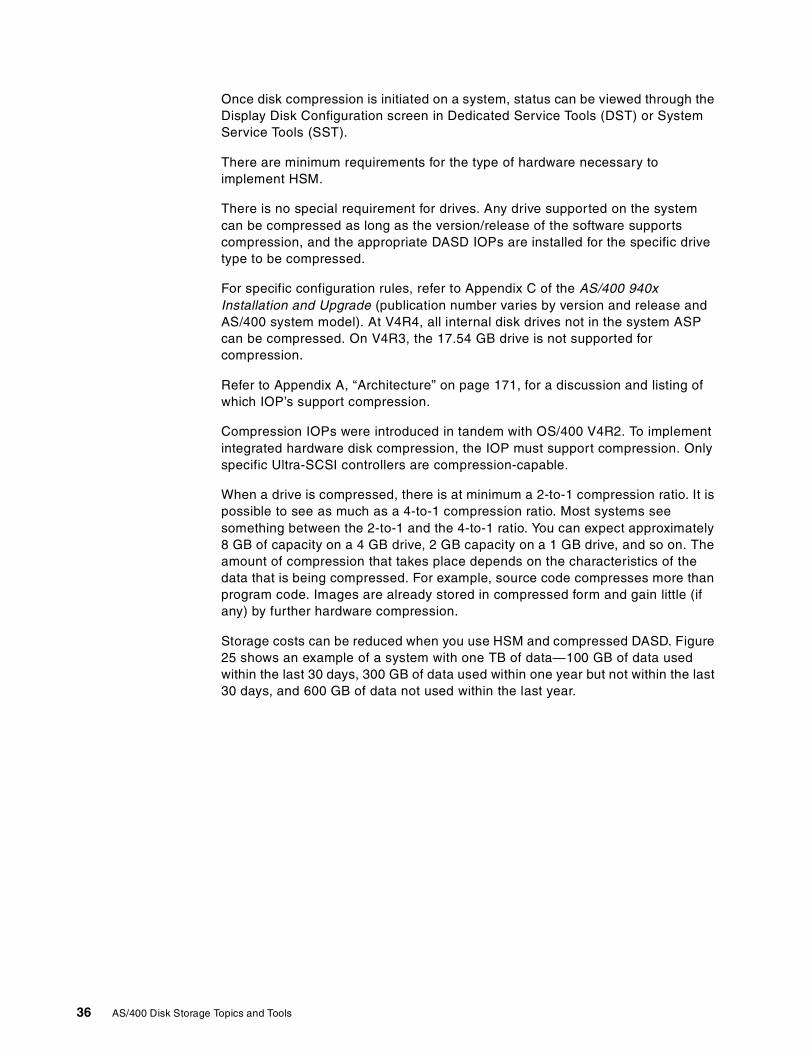
Once disk compression is initiated on a system, status can be viewed through theDisplay Disk Configuration screen in Dedicated Service Tools (DST) or SystemService Tools (SST).
There are minimum requirements for the type of hardware necessary toimplement HSM.
There is no special requirement for drives. Any drive supported on the systemcan be compressed as long as the version/release of the software supportscompression, and the appropriate DASD IOPs are installed for the specific drivetype to be compressed.
For specific configuration rules, refer to Appendix C of the AS/400 940xInstallation and Upgrade (publication number varies by version and release andAS/400 system model). At V4R4, all internal disk drives not in the system ASPcan be compressed. On V4R3, the 17.54 GB drive is not supported forcompression.
Refer to Appendix A, “Architecture” on page 171, for a discussion and listing ofwhich IOP’s support compression.
Compression IOPs were introduced in tandem with OS/400 V4R2. To implementintegrated hardware disk compression, the IOP must support compression. Onlyspecific Ultra-SCSI controllers are compression-capable.
When a drive is compressed, there is at minimum a 2-to-1 compression ratio. It ispossible to see as much as a 4-to-1 compression ratio. Most systems seesomething between the 2-to-1 and the 4-to-1 ratio. You can expect approximately8 GB of capacity on a 4 GB drive, 2 GB capacity on a 1 GB drive, and so on. Theamount of compression that takes place depends on the characteristics of thedata that is being compressed. For example, source code compresses more thanprogram code. Images are already stored in compressed form and gain little (ifany) by further hardware compression.
Storage costs can be reduced when you use HSM and compressed DASD. Figure25 shows an example of a system with one TB of data—100 GB of data usedwithin the last 30 days, 300 GB of data used within one year but not within the last30 days, and 600 GB of data not used within the last year.
36 AS/400 Disk Storage Topics and Tools
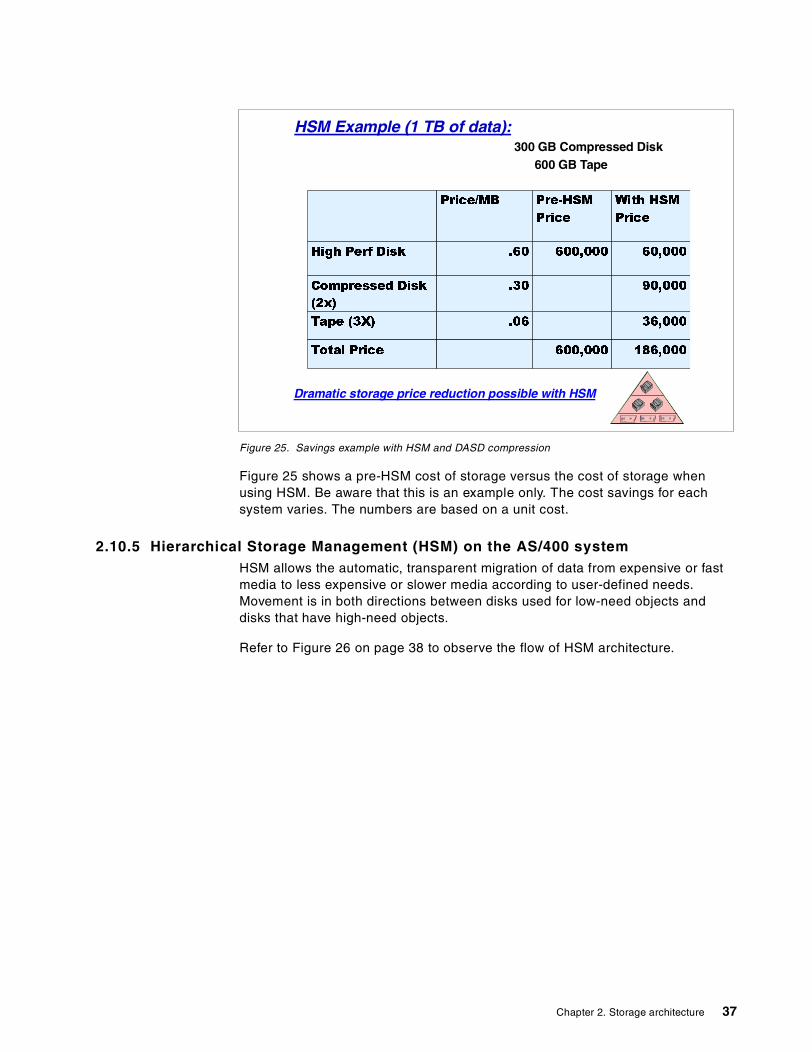
Figure 25. Savings example with HSM and DASD compression
Figure 25 shows a pre-HSM cost of storage versus the cost of storage whenusing HSM. Be aware that this is an example only. The cost savings for eachsystem varies. The numbers are based on a unit cost.
2.10.5 Hierarchical Storage Management (HSM) on the AS/400 systemHSM allows the automatic, transparent migration of data from expensive or fastmedia to less expensive or slower media according to user-defined needs.Movement is in both directions between disks used for low-need objects anddisks that have high-need objects.
Refer to Figure 26 on page 38 to observe the flow of HSM architecture.
HSM Example (1 TB of data):
Dramatic storage price reduction possible with HSM
300 GB Compressed Disk600 GB Tape
Price/MB Pre-HSM
Price
With HSM
Price
High Perf Disk .60 600,000 60,000
Compressed Disk
(2x)
.30 90,000
Tape (3X) .06 36,000
Total Price 600,000 186,000
Chapter 2. Storage architecture 37
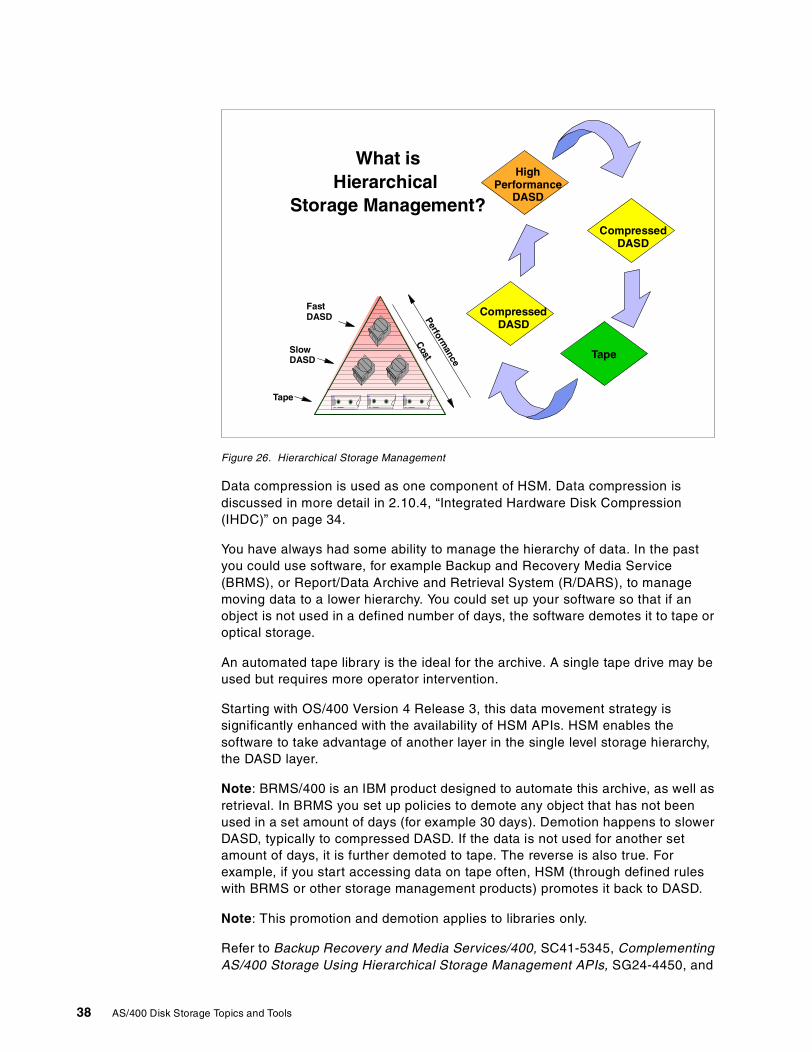
Figure 26. Hierarchical Storage Management
Data compression is used as one component of HSM. Data compression isdiscussed in more detail in 2.10.4, “Integrated Hardware Disk Compression(IHDC)” on page 34.
You have always had some ability to manage the hierarchy of data. In the pastyou could use software, for example Backup and Recovery Media Service(BRMS), or Report/Data Archive and Retrieval System (R/DARS), to managemoving data to a lower hierarchy. You could set up your software so that if anobject is not used in a defined number of days, the software demotes it to tape oroptical storage.
An automated tape library is the ideal for the archive. A single tape drive may beused but requires more operator intervention.
Starting with OS/400 Version 4 Release 3, this data movement strategy issignificantly enhanced with the availability of HSM APIs. HSM enables thesoftware to take advantage of another layer in the single level storage hierarchy,the DASD layer.
Note: BRMS/400 is an IBM product designed to automate this archive, as well asretrieval. In BRMS you set up policies to demote any object that has not beenused in a set amount of days (for example 30 days). Demotion happens to slowerDASD, typically to compressed DASD. If the data is not used for another setamount of days, it is further demoted to tape. The reverse is also true. Forexample, if you start accessing data on tape often, HSM (through defined ruleswith BRMS or other storage management products) promotes it back to DASD.
Note: This promotion and demotion applies to libraries only.
Refer to Backup Recovery and Media Services/400, SC41-5345, ComplementingAS/400 Storage Using Hierarchical Storage Management APIs, SG24-4450, and
Tape
CompressedDASD
CompressedDASD
HighPerformance
DASD
What isHierarchical
Storage Management?
SlowDASD
Tape
FastDASD
Cost
Performance
38 AS/400 Disk Storage Topics and Tools
Hierarchical Storage Management Use, SC41-5351, for further information onBRMS/400.
2.10.6 Auxiliary storage pools (ASP)ASPs were originally developed as a means of recovery to restore after system orstorage failure. Other reasons that warrant the use of multiple ASPs are:
• You cannot afford to mirror or RAID-5 protect the entire disk storagesubsystem, but you can mirror part of it.
• You want performance gains in specific high-need processes.
• You use functions that are not supported in the system ASP, for example,compressed DASD.
• You need to separate journal receivers from their associated journal.
• You need to separate application data requiring large objects and data accessperformance is not critical, for example, using 17.54 GB disk drives for imagedata.
Refer to Figure 27 for a visual example of multiple ASPs.
Figure 27. Auxiliary storage pools
2.10.6.1 Single level storageTo understand ASPs, it is valuable to first understand single level storage, alsoknown as single address architecture. The following provides an analogy ofsingle level storage.
When you put your money into a bank account at your local branch, in your view,the funds now sit in a drawer in that branch. This is your “virtual” view of yourfunds. In all actuality, the funds are invested in your neighbor's mortgage, aforeign business, a local business research department, or the government. Allyou (the system processor) are concerned about is that when you make awithdrawal, the funds are delivered to you. This is much like an application’s viewof data. It does not care where the data is stored, only that it has fast access tothe data when it chooses to do so.
LoadSource
System ASP User ASPused for save/archiveon compressed DASD
User ASPused for journal receivers
ASP 1 ASP 2
ASP 3
Chapter 2. Storage architecture 39
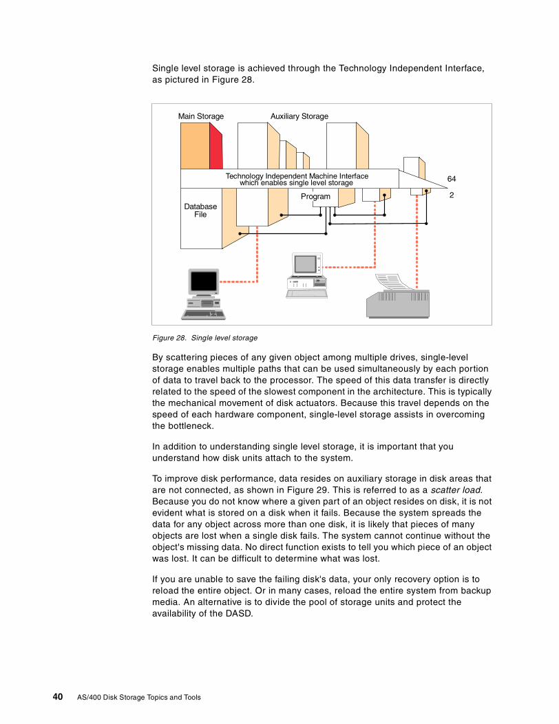
Single level storage is achieved through the Technology Independent Interface,as pictured in Figure 28.
Figure 28. Single level storage
By scattering pieces of any given object among multiple drives, single-levelstorage enables multiple paths that can be used simultaneously by each portionof data to travel back to the processor. The speed of this data transfer is directlyrelated to the speed of the slowest component in the architecture. This is typicallythe mechanical movement of disk actuators. Because this travel depends on thespeed of each hardware component, single-level storage assists in overcomingthe bottleneck.
In addition to understanding single level storage, it is important that youunderstand how disk units attach to the system.
To improve disk performance, data resides on auxiliary storage in disk areas thatare not connected, as shown in Figure 29. This is referred to as a scatter load.Because you do not know where a given part of an object resides on disk, it is notevident what is stored on a disk when it fails. Because the system spreads thedata for any object across more than one disk, it is likely that pieces of manyobjects are lost when a single disk fails. The system cannot continue without theobject's missing data. No direct function exists to tell you which piece of an objectwas lost. It can be difficult to determine what was lost.
If you are unable to save the failing disk's data, your only recovery option is toreload the entire object. Or in many cases, reload the entire system from backupmedia. An alternative is to divide the pool of storage units and protect theavailability of the DASD.
DatabaseFile
Main Storage Auxiliary Storage
Technology Independent Machine Interfacewhich enables single level storage
Program
64
2
40 AS/400 Disk Storage Topics and Tools
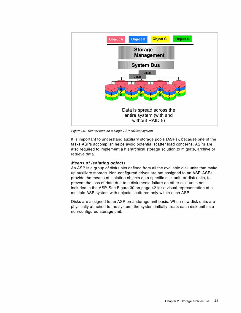
Figure 29. Scatter load on a single ASP AS/400 system
It is important to understand auxiliary storage pools (ASPs), because one of thetasks ASPs accomplish helps avoid potential scatter load concerns. ASPs arealso required to implement a hierarchical storage solution to migrate, archive orretrieve data.
Means of isolating objectsAn ASP is a group of disk units defined from all the available disk units that makeup auxiliary storage. Non-configured drives are not assigned to an ASP. ASPsprovide the means of isolating objects on a specific disk unit, or disk units, toprevent the loss of data due to a disk media failure on other disk units notincluded in the ASP. See Figure 30 on page 42 for a visual representation of amultiple ASP system with objects scattered only within each ASP.
Disks are assigned to an ASP on a storage unit basis. When new disk units arephysically attached to the system, the system initially treats each disk unit as anon-configured storage unit.
System BusCTLR
DC
AB
DC
AB
DC
AB
DC
AB
CTLR
DC
AB
DC
AB
DC
AB
DC
AB
StorageManagement
Data is spread across theentire system (with and
without RAID 5)
Object B Object CObject A Object D
Chapter 2. Storage architecture 41
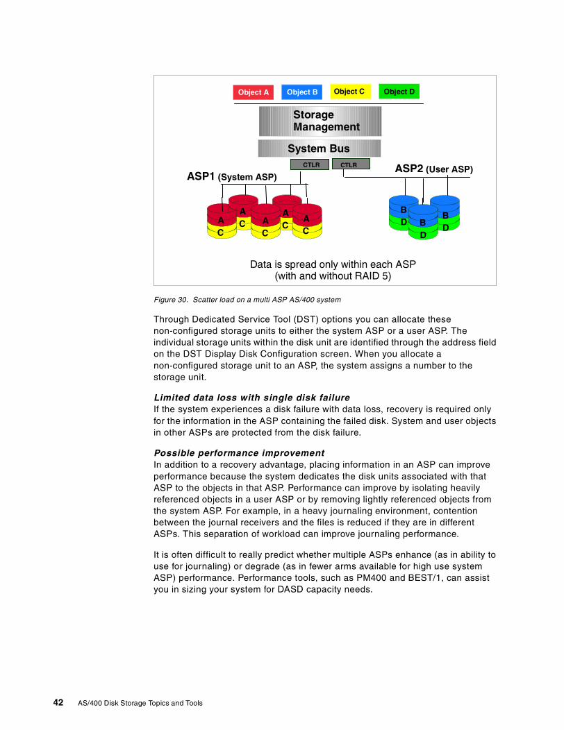
Figure 30. Scatter load on a multi ASP AS/400 system
Through Dedicated Service Tool (DST) options you can allocate thesenon-configured storage units to either the system ASP or a user ASP. Theindividual storage units within the disk unit are identified through the address fieldon the DST Display Disk Configuration screen. When you allocate anon-configured storage unit to an ASP, the system assigns a number to thestorage unit.
Limited data loss with single disk failureIf the system experiences a disk failure with data loss, recovery is required onlyfor the information in the ASP containing the failed disk. System and user objectsin other ASPs are protected from the disk failure.
Possible performance improvementIn addition to a recovery advantage, placing information in an ASP can improveperformance because the system dedicates the disk units associated with thatASP to the objects in that ASP. Performance can improve by isolating heavilyreferenced objects in a user ASP or by removing lightly referenced objects fromthe system ASP. For example, in a heavy journaling environment, contentionbetween the journal receivers and the files is reduced if they are in differentASPs. This separation of workload can improve journaling performance.
It is often difficult to really predict whether multiple ASPs enhance (as in ability touse for journaling) or degrade (as in fewer arms available for high use systemASP) performance. Performance tools, such as PM400 and BEST/1, can assistyou in sizing your system for DASD capacity needs.
System BusCTLRCTLR
StorageManagement
Data is spread only within each ASP(with and without RAID 5)
Object B Object CObject A Object D
DB
DB
DB
CA
CA
CA
CA
CA
CA
CA
CA
ASP1 (System ASP)ASP2 (User ASP)
42 AS/400 Disk Storage Topics and Tools
System ASPThe System ASP (ASP 1) is created by the system when LIC is installed. It isalways configured. ASP 1 contains the LIC, licensed programs, and systemlibraries. The System ASP also contains all other configured disk units that arenot assigned to a User ASP.
User ASPsA user ASP is created by grouping together a physical set of disk units andassigning them a unique number, 2 through 16 (ASP 1 is always reserved as theSystem ASP).
User ASPs were originally developed for journaling, receivers, and save files.(Save files can store data, then offload to tape later, as in system backup, toreduce system down time). Later development allowed creating a library in a userASP. This allowed pointers for the user ASP to be in the user ASP, allowing betterASP recovery. User ASPs can be used to isolate libraries and objects withinthese libraries from the system ASP. If a library exists in a user ASP, all objects inthe library must be in the same ASP as the library.
Refer to AS/400 Backup and Recovery, SC41-5304, for a list of object types thatare not allowed in a user ASP.
Overflowed user ASPWhen a user ASP becomes full, objects can overflow into the system ASP. If theuser ASP overflows, the overflow status for the ASP should be handled as soonas possible because if a data-loss failure occurs that causes either the systemASP or the user ASP to be cleared, both ASPs are cleared. When creating userASPs a threshold value can be defined using DST or SST menu options. FromSST, select the Work with disk configuration option. Then, select the Work withASP threshold option from the next menu and make your change. If the thresholdis not specified, the default setting by the system is 90% for a system ASP or auser ASP.
As of V2R2, if a user ASP overflows, as objects are deleted from the user ASP,the overflowed objects in the system ASP are “copied” back into the user ASPduring an IPL, as space becomes available.
Full system ASPIf the system ASP fills to capacity, the system ends abnormally. You must IPL thesystem and take corrective action, such as deleting objects, to reduce the storageutilization within the system ASP. To avoid filling the system ASP, specify athreshold value for the ASP. Use the system value QSTGLOWLMT or use SST orDST screens by selecting the menu option Work with disk configuration. Then,
If the disk configuration contains disk units of significantly different capacitieswithin an ASP, performance can degrade. Performance can also besignificantly impacted by too few disk arms. The Disk Arm Requirements whitepaper offers more information and access to a tool to help assess this factor.You may also want to refer to the Version Performance Considerations whitepaper. Both white papers are available on the Web at:http://www.ibm.com.as400/developer/performance
Note
Chapter 2. Storage architecture 43
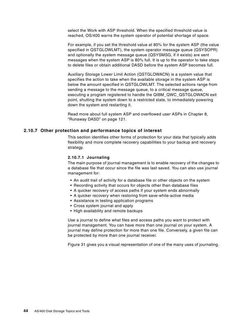
select the Work with ASP threshold. When the specified threshold value isreached, OS/400 warns the system operator of potential shortage of space.
For example, if you set the threshold value at 80% for the system ASP (the valuespecified in QSTGLOWLMT), the system operator message queue (QSYSOPR)and optionally the system message queue (QSYSMSG, if it exists) are sentmessages when the system ASP is 80% full. It is up to the operator to take stepsto delete files or obtain additional DASD before the system ASP becomes full.
Auxiliary Storage Lower Limit Action (QSTGLOWACN) is a system value thatspecifies the action to take when the available storage in the system ASP isbelow the amount specified in QSTGLOWLMT. The selected actions range fromsending a message to the message queue, to a critical message queue,executing a program registered to handle the QIBM_QWC_QSTGLOWACN exitpoint, shutting the system down to a restricted state, to immediately poweringdown the system and restarting it.
Read more about full system ASP and overflowed user ASPs in Chapter 8,“Runaway DASD” on page 121.
2.10.7 Other protection and performance topics of interestThis section identifies other forms of protection for your data that typically addsflexibility and more complete recovery capabilities to your backup and recoverystrategy.
2.10.7.1 JournalingThe main purpose of journal management is to enable recovery of the changes toa database file that occur since the file was last saved. You can also use journalmanagement for:
• An audit trail of activity for a database file or other objects on the system• Recording activity that occurs for objects other than database files• A quicker recovery of access paths if your system ends abnormally• A quicker recovery when restoring from save-while-active media• Assistance in testing application programs• Cross system journal and apply• High availability and remote backups
Use a journal to define what files and access paths you want to protect withjournal management. You can have more than one journal on your system. Ajournal may define protection for more than one file. Conversely, a given file canbe protected by more than one journal receiver.
Figure 31 gives you a visual representation of one of the many uses of journaling.
44 AS/400 Disk Storage Topics and Tools
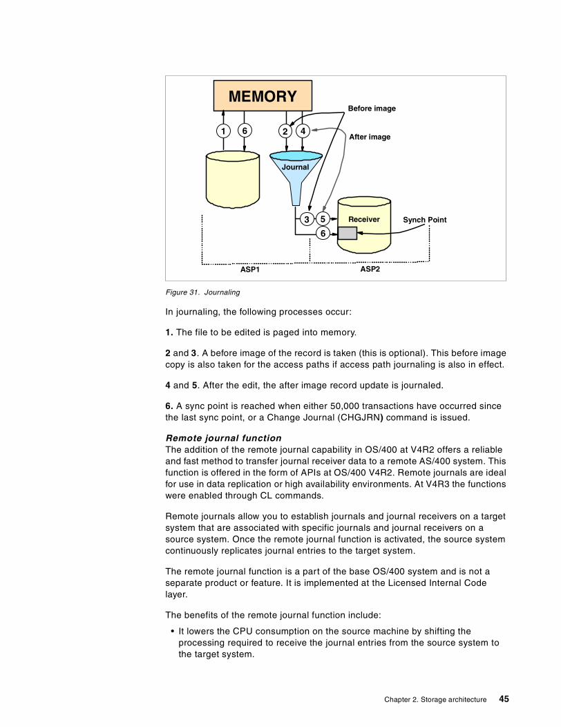
Figure 31. Journaling
In journaling, the following processes occur:
1. The file to be edited is paged into memory.
2 and 3. A before image of the record is taken (this is optional). This before imagecopy is also taken for the access paths if access path journaling is also in effect.
4 and 5. After the edit, the after image record update is journaled.
6. A sync point is reached when either 50,000 transactions have occurred sincethe last sync point, or a Change Journal (CHGJRN) command is issued.
Remote journal functionThe addition of the remote journal capability in OS/400 at V4R2 offers a reliableand fast method to transfer journal receiver data to a remote AS/400 system. Thisfunction is offered in the form of APIs at OS/400 V4R2. Remote journals are idealfor use in data replication or high availability environments. At V4R3 the functionswere enabled through CL commands.
Remote journals allow you to establish journals and journal receivers on a targetsystem that are associated with specific journals and journal receivers on asource system. Once the remote journal function is activated, the source systemcontinuously replicates journal entries to the target system.
The remote journal function is a part of the base OS/400 system and is not aseparate product or feature. It is implemented at the Licensed Internal Codelayer.
The benefits of the remote journal function include:
• It lowers the CPU consumption on the source machine by shifting theprocessing required to receive the journal entries from the source system tothe target system.
MEMORY
1 6 2 4
Journal
Receiver Synch Point
6
53
ASP2ASP1
Before image
After image
Chapter 2. Storage architecture 45
• It eliminates the need to buffer journal entries to a temporary area beforetransmitting them from the source machine to the target machine. Thistranslates into less disk writes and greater DASD efficiency on the sourcesystem.
• Since it is implemented in microcode, it significantly improves the replicationperformance of journal entries and allows database images to be sent to thetarget system in real-time. This real-time operation is called the synchronousdelivery mode. If the synchronous delivery mode is used, the journal entriesare guaranteed to be in main storage on the target system prior to controlbeing returned to the application on the source machine.
• It allows the journal receiver save and restore operations to be moved to thetarget system. This way, the resource utilization on the source machine can bereduced.
For additional reading on remote journals, refer to the redbook AS/400 RemoteJournal Function for High Availability and Data Replication, SG24-5189.
2.10.7.2 ClusteringCluster technology is implemented on the AS/400 to provide availability duringboth planned and unplanned outages. Starting from 2.1, “Direct access storagedevice (DASD)” on page 19, and onward, it should be clear that the AS/400developers have spent a significant amount of design resource to enable highlevels of availability in a single system environment. This highly reliable design(as measured in a Gartner Group report) has long been used for unplannedoutages by the AS/400 customer. In today's world, however, it is becomingincreasingly clear that there is no time for any unplanned outages, or evenplanned outages, for that matter. Clusters are implemented to reduce down timedue to planned outages and site disasters. In an AS/400 installation, the lion'sshare of down time comes from planned outages. Providing system availabilityduring planned outages results in increased unplanned outage coverage as aside benefit.
To further address the needs of the continuous availability market, the AS/400development team is investing in cluster technology. Significant advancedfeatures and functions were introduced in V4R4 that put the AS/400 system in aleadership position. Cluster technology has been around for many years but onlyrecently have common terms and concepts begun to emerge. The AS/400 systemdesign has adopted these concepts and integrated the infrastructure needed toachieve a level of standardization, an advancement of cluster technology, and theinvolvement of the Solution Developer (SD) and the cluster middleware businesspartner in the total solution. While the AS/400 system provides the basic clusterinfrastructure, the cluster middleware business partner provides data resiliencyand the Solution Developer provides application resiliency. Together, these threeparts provide the whole solution to continuous availability.
Cluster Resource Services represents the cluster technology that AS/400provides in V4R4. It consists of an open set of APIs which applications can use tocreate and manage a cluster.
Data Resiliency is the maintaining of one or more copies of the application dataon one or more separate systems. DataMirror, Lakeview Technology, and VisionSolutions have provided sophisticated data replication solutions for many years.
46 AS/400 Disk Storage Topics and Tools
New or updated products that take advantage of cluster resource services areavailable by the cluster middleware business partners.
DataMirror announced availability of their iCluster product suite beginningJuly 14, 1999. Vision Solutions announced availability of their Vision SuiteVersion 6.3 starting July 15, 1999.
Cluster Management is new for V4R4. This is the entry point for the customerwho has the responsibility for first choosing a cluster middleware businesspartner's product. When installed, the cluster management features are used toconfigure the customer's systems into a cluster and define how the systemsparticipate in the backup strategy. Then the application which is to be activated ashighly available is selected. Cluster Management handles ClusterProven forAS/400 applications, providing automatic configuration and activation.
Vision Solutions’ Vision Suite version 6.3 handles ClusterProven for AS/400applications.
For a simple example configuration, refer to Figure 32 on page 48.
To read more about clustering, visit these Web sites:
• http://www.as400.ibm.com/ha/sec2.htm
• http://www.as400.ibm.com/ha/sec23.htm
• http://www.as400.ibm.com/ha/sec24.htm
2.10.7.3 Multiple SystemsPrior to the availability of a clustering implementation, duplication of systems wasperformed in a less efficient manner—through a communications link(Token-Ring, OptiConnect, dial-up, or other). With a central site or home officeinstallation in place, a second (and sometimes third) system is separatelymaintained at a remote site location. The systems are kept in synchronization byperiodic transmission of updates through the communication link. For example,the home office sends updates to the remote location for a duplicate set of data.The reverse could also be true.
In this implementation of multiple systems, the system administrator isresponsible for twice the amount of documentation and management.
An example of a multiple system configuration can be observed in Figure 32.
Chapter 2. Storage architecture 47
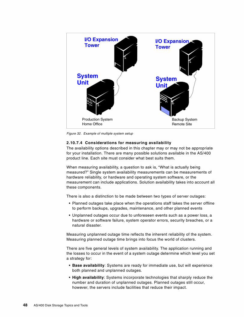
Figure 32. Example of multiple system setup
2.10.7.4 Considerations for measuring availabilityThe availability options described in this chapter may or may not be appropriatefor your installation. There are many possible solutions available in the AS/400product line. Each site must consider what best suits them.
When measuring availability, a question to ask is, “What is actually beingmeasured?” Single system availability measurements can be measurements ofhardware reliability, or hardware and operating system software, or themeasurement can include applications. Solution availability takes into account allthese components.
There is also a distinction to be made between two types of server outages:
• Planned outages take place when the operations staff takes the server offlineto perform backups, upgrades, maintenance, and other planned events
• Unplanned outages occur due to unforeseen events such as a power loss, ahardware or software failure, system operator errors, security breaches, or anatural disaster.
Measuring unplanned outage time reflects the inherent reliability of the system.Measuring planned outage time brings into focus the world of clusters.
There are five general levels of system availability. The application running andthe losses to occur in the event of a system outage determine which level you seta strategy for:
• Base availability: Systems are ready for immediate use, but will experienceboth planned and unplanned outages.
• High availability: Systems incorporate technologies that sharply reduce thenumber and duration of unplanned outages. Planned outages still occur,however, the servers include facilities that reduce their impact.
SystemUnit
I/O ExpansionTower
SystemUnit
I/O ExpansionTower
Production SystemHome Office
Backup SystemRemote Site
48 AS/400 Disk Storage Topics and Tools
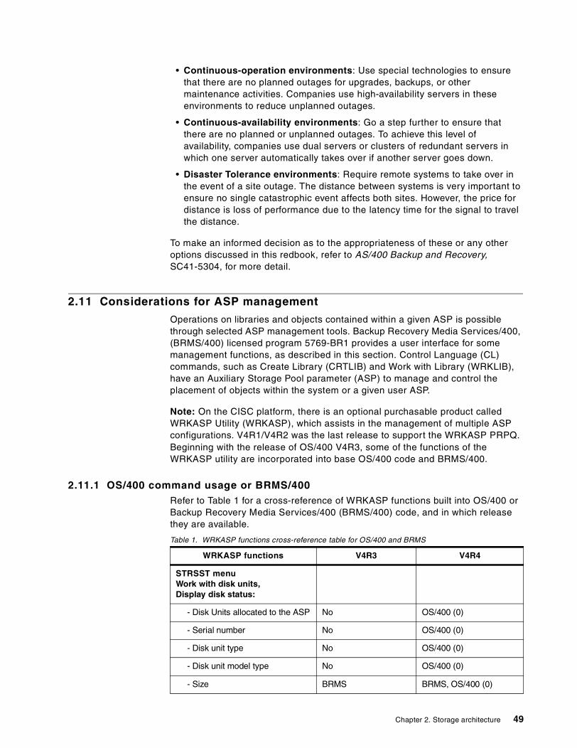
• Continuous-operation environments: Use special technologies to ensurethat there are no planned outages for upgrades, backups, or othermaintenance activities. Companies use high-availability servers in theseenvironments to reduce unplanned outages.
• Continuous-availability environments: Go a step further to ensure thatthere are no planned or unplanned outages. To achieve this level ofavailability, companies use dual servers or clusters of redundant servers inwhich one server automatically takes over if another server goes down.
• Disaster Tolerance environments: Require remote systems to take over inthe event of a site outage. The distance between systems is very important toensure no single catastrophic event affects both sites. However, the price fordistance is loss of performance due to the latency time for the signal to travelthe distance.
To make an informed decision as to the appropriateness of these or any otheroptions discussed in this redbook, refer to AS/400 Backup and Recovery,SC41-5304, for more detail.
2.11 Considerations for ASP management
Operations on libraries and objects contained within a given ASP is possiblethrough selected ASP management tools. Backup Recovery Media Services/400,(BRMS/400) licensed program 5769-BR1 provides a user interface for somemanagement functions, as described in this section. Control Language (CL)commands, such as Create Library (CRTLIB) and Work with Library (WRKLIB),have an Auxiliary Storage Pool parameter (ASP) to manage and control theplacement of objects within the system or a given user ASP.
Note: On the CISC platform, there is an optional purchasable product calledWRKASP Utility (WRKASP), which assists in the management of multiple ASPconfigurations. V4R1/V4R2 was the last release to support the WRKASP PRPQ.Beginning with the release of OS/400 V4R3, some of the functions of theWRKASP utility are incorporated into base OS/400 code and BRMS/400.
2.11.1 OS/400 command usage or BRMS/400Refer to Table 1 for a cross-reference of WRKASP functions built into OS/400 orBackup Recovery Media Services/400 (BRMS/400) code, and in which releasethey are available.
Table 1. WRKASP functions cross-reference table for OS/400 and BRMS
WRKASP functions V4R3 V4R4
STRSST menuWork with disk units,Display disk status:
- Disk Units allocated to the ASP No OS/400 (0)
- Serial number No OS/400 (0)
- Disk unit type No OS/400 (0)
- Disk unit model type No OS/400 (0)
- Size BRMS BRMS, OS/400 (0)
Chapter 2. Storage architecture 49
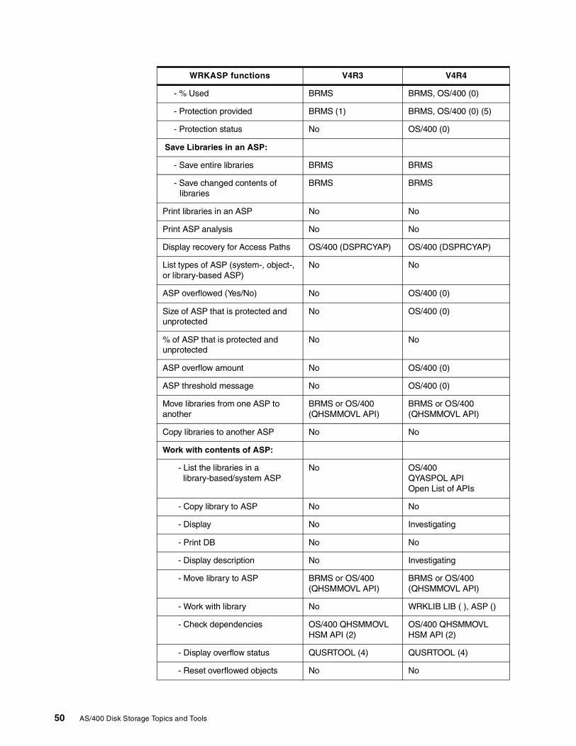
- % Used BRMS BRMS, OS/400 (0)
- Protection provided BRMS (1) BRMS, OS/400 (0) (5)
- Protection status No OS/400 (0)
Save Libraries in an ASP:
- Save entire libraries BRMS BRMS
- Save changed contents oflibraries
BRMS BRMS
Print libraries in an ASP No No
Print ASP analysis No No
Display recovery for Access Paths OS/400 (DSPRCYAP) OS/400 (DSPRCYAP)
List types of ASP (system-, object-,or library-based ASP)
No No
ASP overflowed (Yes/No) No OS/400 (0)
Size of ASP that is protected andunprotected
No OS/400 (0)
% of ASP that is protected andunprotected
No No
ASP overflow amount No OS/400 (0)
ASP threshold message No OS/400 (0)
Move libraries from one ASP toanother
BRMS or OS/400(QHSMMOVL API)
BRMS or OS/400(QHSMMOVL API)
Copy libraries to another ASP No No
Work with contents of ASP:
- List the libraries in alibrary-based/system ASP
No OS/400QYASPOL APIOpen List of APIs
- Copy library to ASP No No
- Display No Investigating
- Print DB No No
- Display description No Investigating
- Move library to ASP BRMS or OS/400(QHSMMOVL API)
BRMS or OS/400(QHSMMOVL API)
- Work with library No WRKLIB LIB ( ), ASP ()
- Check dependencies OS/400 QHSMMOVLHSM API (2)
OS/400 QHSMMOVLHSM API (2)
- Display overflow status QUSRTOOL (4) QUSRTOOL (4)
- Reset overflowed objects No No
WRKASP functions V4R3 V4R4
50 AS/400 Disk Storage Topics and Tools
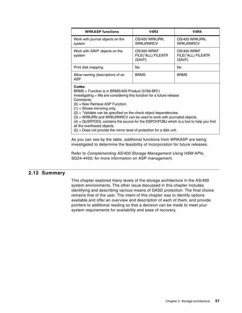
As you can see by the table, additional functions from WRKASP are beinginvestigated to determine the feasibility of incorporation for future releases.
Refer to Complementing AS/400 Storage Management Using HSM APIs,SG24-4450, for more information on ASP management.
2.12 Summary
This chapter explored many levels of the storage architecture in the AS/400system environments. The other issue discussed in this chapter includesidentifying and describing various means of DASD protection. The final choiceremains that of the user. The intent of this chapter was to identify optionsavailable and offer an overview and description of each of them, and providepointers to additional reading so that a decision can be made to meet yoursystem requirements for availability and ease of recovery.
Work with journal objects on thesystem
OS/400 WRKJRN,WRKJRNRCV
OS/400 WRKJRN,WRKJRNRCV
Work with SAVF objects on thesystem
OS/400 WRKFFILE(*ALL) FILEATR(SAVF)
OS/400 WRKFFILE(*ALL) FILEATR(SAVF)
Print disk mapping No No
Allow naming (description) of anASP
BRMS BRMS
Codes:BRMS = Function is in BRMS/400 Product (5769-BR1)Investigating = We are considering this function for a future releaseComments:(0) = New Retrieve ASP Function.(1) = Shows mirroring only.(2) = *Validate can be specified on the check object dependencies.(3) = WRKJRN and WRKJRNRCV can be used to work with journaled objects.(4) = QUSRTOOL contains the source for the DSPOVFOBJ which is a tool to help you findall the overflowed objects.(5) = Does not provide the mirror level of protection for a disk unit.
WRKASP functions V4R3 V4R4
Chapter 2. Storage architecture 51

52 AS/400 Disk Storage Topics and Tools
Chapter 3. Storage options
This chapter identifies many options available for storage media of a permanentnature. The components described include current devices, as well as anintroduction to storage options new to the AS/400 system and how they can fitinto the structure of your AS/400 system environment to enhance and strengthenyour storage needs.
Non-removable storage is described in Appendix C, “Non-removable storage(DASD)” on page 195.
3.1 Digital Versatile Disk (DVD)
Digital Versatile Disk-Random Access Memory (DVD-RAM) is a rewriteable,optical storage technology that offers significant cost savings over the currenttape and CD-ROM technologies. The AS/400 DVD device will be functionallyequivalent to tape and CD-ROM for save and restore, software installation,backup and disaster recovery, and for service personnel to use when taking mainstore dumps. Since the DVD drive is downward read compatible to CD-ROMmedia, CD-ROM media from software distribution (PID) can be read using DVD.
DVD RAM media has a capacity of 4.7 GB on a single side compared to CD-ROM650 MB capacity. A DVD device will occupy the same integrated tray now used byCD-ROM devices on the AS/400 system. Similar to CD-ROM, the DVD media is120 mm optical media. The DVD-RAM media may require the use of a cartridgecarrier similar to that used by the 130 mm IBM optical media. The drive readsCD-ROM media as well as DVD-ROM media. Neither requires a cartridge andcan be loaded as is into the same media tray that also fits a cartridge. In eithercase, all media used is front-loaded into the drive.
For additional detail regarding uses of DVD in the AS/400 system, refer toChapter 2, “Storage architecture” on page 19.
3.2 CD-ROM
AS/400e server code is distributed on CD-ROM media. The CD-ROM drive isstandard on all AS/400 models and is therefore not identified with a separatefeature on the system unit. It can also be used for alternate IPL, but not as a saveand restore device for the system. A maximum of one CD-ROM can be orderedper expansion tower.
LPAR support and CD-ROM feature descriptionsSee Table 2 on page 54 for specific feature code and installation rules andrequirements.
© Copyright IBM Corp. 2000 53
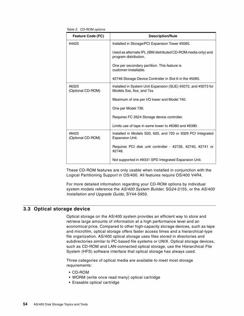
Table 2. CD-ROM options
These CD-ROM features are only usable when installed in conjunction with theLogical Partitioning Support in OS/400. All features require OS/400 V4R4.
For more detailed information regarding your CD-ROM options by individualsystem models reference the AS/400 System Builder, SG24-2155, or the AS/400Installation and Upgrade Guide, SY44-5950.
3.3 Optical storage device
Optical storage on the AS/400 system provides an efficient way to store andretrieve large amounts of information at a high performance level and aneconomical price. Compared to other high-capacity storage devices, such as tapeand microfilm, optical storage offers faster access times and a hierarchical-typefile organization. AS/400 optical storage uses files stored in directories andsubdirectories similar to PC-based file systems or UNIX. Optical storage devices,such as CD-ROM and LAN-connected optical storage, use the Hierarchical FileSystem (HFS) software interface that optical storage has always used.
Three categories of optical media are available to meet most storagerequirements:
• CD-ROM• WORM (write once read many) optical cartridge• Erasable optical cartridge
Feature Code (FC) Description/Rule
#4425 Installed in Storage/PCI Expansion Tower #5065.
Used as alternate IPL (IBM distributed CD-ROM media only) andprogram distribution.
One per secondary partition. This feature iscustomer-installable.
#2748 Storage Device Controller in Slot 6 in the #5065.
#6325(Optional CD-ROM)
Installed in System Unit Expansion (SUE) #5072, and #5073 forModels Sxx, 6xx, and 7xx.
Maximum of one per I/O tower and Model 740.
One per Model 730.
Requires FC 2624 Storage device controller.
Limits use of tape in same tower to #6380 and #6390.
#6425(Optional CD-ROM)
Installed in Models S20, 620, and 720 or 9329 PCI IntegratedExpansion Unit.
Requires PCI disk unit controller - #2726, #2740, #2741 or#2748.
Not supported in #9331 SPD Integrated Expansion Unit.
54 AS/400 Disk Storage Topics and Tools
CD-ROMS are single-sided disks and are the same size as those commonly usedin audio CD players. The CD-ROM data format is identical to the one used withpersonal computers. Therefore, it may be possible to develop CD-ROMs for useon both personal computers and the AS/400 system. The other two forms(WORM and erasable) are two-sided disks that are contained within a cartridgeshell.
CD-ROM is a read-only format that is optimized for read performance. CD-ROMsare ideal for the wide-scale distribution of programs and data. Access to CD-ROMis supported through the Hierarchical File System, Integrated File System, andsave and restore interfaces.
All AS/400 Advanced Series systems include a rack-mounted CD-ROM drive thatis ideal for program and data distribution. The CD-ROM drive is primarilyintended as a program and data delivery device. Even though many users canpotentially access it simultaneously, the drive accesses one CD-ROM at a time.
WORM storage is an economical way to archive data, yet still have it quickly andeasily accessible. WORM media is available in 1x (650 MB), 2x (1.3 GB), and 4x(2.6 GB) capacities. An erasable cartridge offers the most flexibility with the samecapabilities as magnetic (DASD) storage, but with much higher capacities andlower cost. Erasable media is available in 1x (650 MB), 2x (1.3 GB), and 4x (2.6GB) capacities. Both WORM and erasable cartridges have a sector size of 1024bytes/sector.
Optical media libraries come in a variety of configurations designed around thedifferent forms of media and connection options. Optical media libraries rangefrom a single cartridge standalone model through models that are capable ofloading 258 optical cartridges and four disk drives. Optical media libraries may bedirectly connected to the AS/400 system for best functionality and performance.Or they may be connected through a LAN to allow independent access by PCs orother AS/400 systems.
For additional reading on optical library solutions, especially the 3995 opticallibrary, refer to this site on the Web:http://www.storage.ibm.com/hardsoft/opticalstor/index.html
Optical storage device connectivityYou can connect optical media libraries to your AS/400 system in two ways:directly attached and LAN attached.
In the directly-attached method, a multi-wire cable connects the library to an I/Oprocessor (IOP) card within the AS/400 system. Directly-attached librariessupport nearly all Hierarchical File System (HFS) application programminginterfaces, most Integrated File System commands, and AS/400 save and restorecommands. These libraries may be accessed by other LAN-connected systemsby using the Integrated File System.
LAN-connected optical media libraries can be used only through the HFSinterface. The libraries can be accessed simultaneously either by several AS/400systems or any other devices on the LAN. LAN-connected optical media librarieshave a controlling PC and do not require an AS/400 system that acts as acontroller. LAN-attached optical media libraries are often referred to as opticalservers.
Chapter 3. Storage options 55
3.4 Removable storage (tape)
Removable storage is a functional unit that houses a magnetic media onto whichdata is written, can be retained at a location physically apart from the system unit,and from which data can be retrieved onto online storage (usually disk). For thepurposes of our discussion, “tape units” are termed removable storage.
Tape media provides relatively large amounts of storage space with a greatercapacity than direct access storage drives (DASD or disks), but slower speed(and, therefore, less cost on a MB per MB scale). Rewritable tapes provide asstorage capacity that is practically unlimited with the capacity divided intoseparate media units. Removable tape allows you to transport data from systemto system (assuming each system is equipped with compatible drives) andprovides offline storage for archival and recovery purposes.
In selecting tape storage to solve a business requirement, both the financial anddata requirements need to be examined. Aspects of data requirements includethe amount of data to be stored, the performance when reading and writing data,archive and retrieval capabilities, and the level of automation required.
For a table that compares tape subsystems that can attach to the AS/400 system,refer to the AS/400e System Handbook, GA19-5486. This table indicates whetherthe attachment IOP supports Hardware Data Compression (HDC) and whetherthe tape subsystem controller supports a compaction algorithm, either ImprovedData Recording Capability (IDRC) or Lempel Ziv 1 (LZ1). These algorithmsenable more data to be written to tape up to the maximum shown. You can alsolocate this table on the Web at: http://www.as400.ibm.com/handbook/5486MagC.html
The AS/400e System Handbook, GA19-5486, also offers a detailed listing ofmagnetic media controllers, and devices and the AS/400 models to which theyattach.
3.5 Summary
For additional reading on storage options, visit the storage solutions Web siteat: http://www.storage.ibm.com
56 AS/400 Disk Storage Topics and Tools
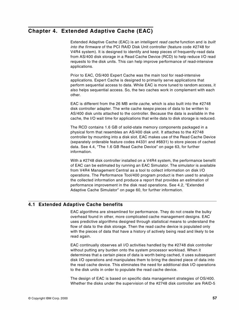
Chapter 4. Extended Adaptive Cache (EAC)
Extended Adaptive Cache (EAC) is an intelligent read cache function and is builtinto the firmware of the PCI RAID Disk Unit controller (feature code #2748 forV4R4 system). It is designed to identify and keep pieces of frequently-read datafrom AS/400 disk storage in a Read Cache Device (RCD) to help reduce I/O readrequests to the disk units. This can help improve performance of read-intensiveapplications.
Prior to EAC, OS/400 Expert Cache was the main tool for read-intensiveapplications. Expert Cache is designed to primarily serve applications thatperform sequential access to data. While EAC is more tuned to random access, italso helps sequential access. So, the two caches work in complement with eachother.
EAC is different from the 26 MB write cache, which is also built into the #2748disk controller adapter. The write cache keeps pieces of data to be written toAS/400 disk units attached to the controller. Because the data is available in thecache, the I/O wait time for applications that write data to disk storage is reduced.
The RCD contains 1.6 GB of solid-state memory components packaged in aphysical form that resembles an AS/400 disk unit. It attaches to the #2748controller by mounting into a disk slot. EAC makes use of the Read Cache Device(separately orderable feature codes #4331 and #6831) to store pieces of cacheddata. See 4.4, “The 1.6 GB Read Cache Device” on page 63, for furtherinformation.
With a #2748 disk controller installed on a V4R4 system, the performance benefitof EAC can be estimated by running an EAC Simulator. The simulator is availablefrom V4R4 Management Central as a tool to collect information on disk I/Ooperations. The Performance Tool/400 program product is then used to analyzethe collected information and produce a report that provides an estimation ofperformance improvement in the disk read operations. See 4.2, “ExtendedAdaptive Cache Simulator” on page 60, for further information.
4.1 Extended Adaptive Cache benefits
EAC algorithms are streamlined for performance. They do not create the bulkyoverhead found in other, more complicated cache management designs. EACuses predictive algorithms designed through statistical means to understand theflow of data to the disk storage. Then the read cache device is populated onlywith the pieces of data that have a history of actively being read and likely to beread again.
EAC continually observes all I/O activities handled by the #2748 disk controllerwithout putting any burden onto the system processor workload. When itdetermines that a certain piece of data is worth being cached, it uses subsequentdisk I/O operations and manipulates them to bring the desired piece of data intothe read cache device. This eliminates the need for additional disk I/O operationsto the disk units in order to populate the read cache device.
The design of EAC is based on specific data management strategies of OS/400.Whether the disks under the supervision of the #2748 disk controller are RAID-5
© Copyright IBM Corp. 2000 57
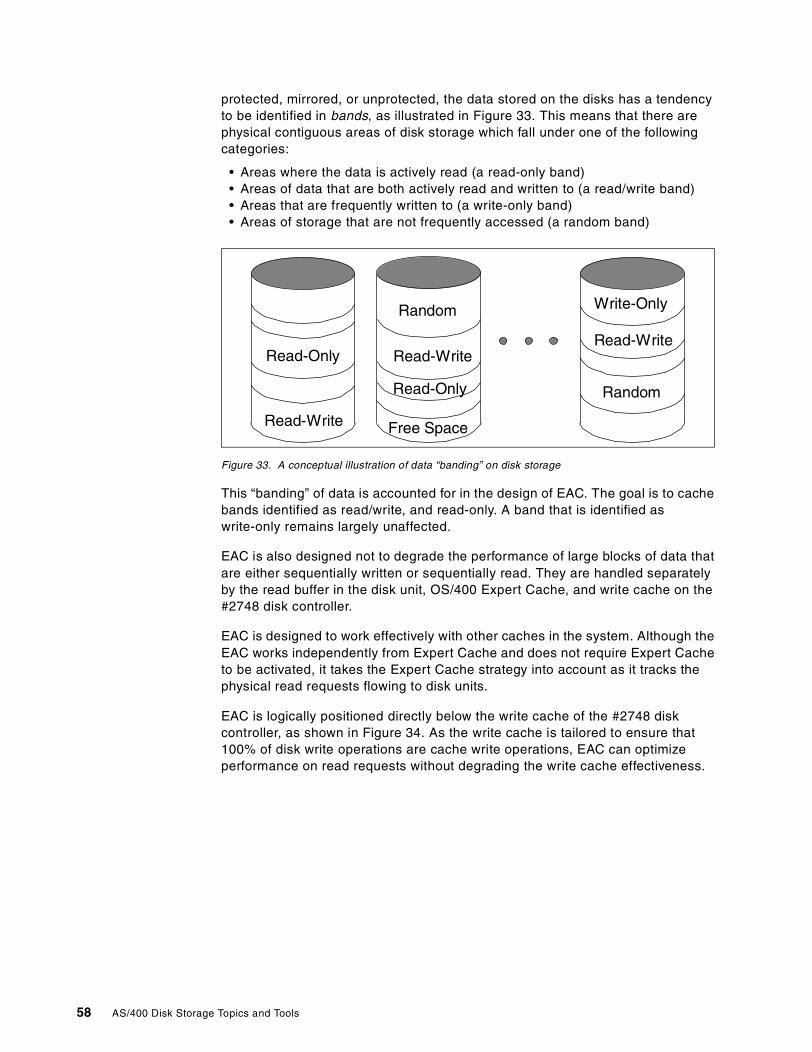
protected, mirrored, or unprotected, the data stored on the disks has a tendencyto be identified in bands, as illustrated in Figure 33. This means that there arephysical contiguous areas of disk storage which fall under one of the followingcategories:
• Areas where the data is actively read (a read-only band)• Areas of data that are both actively read and written to (a read/write band)• Areas that are frequently written to (a write-only band)• Areas of storage that are not frequently accessed (a random band)
Figure 33. A conceptual illustration of data “banding” on disk storage
This “banding” of data is accounted for in the design of EAC. The goal is to cachebands identified as read/write, and read-only. A band that is identified aswrite-only remains largely unaffected.
EAC is also designed not to degrade the performance of large blocks of data thatare either sequentially written or sequentially read. They are handled separatelyby the read buffer in the disk unit, OS/400 Expert Cache, and write cache on the#2748 disk controller.
EAC is designed to work effectively with other caches in the system. Although theEAC works independently from Expert Cache and does not require Expert Cacheto be activated, it takes the Expert Cache strategy into account as it tracks thephysical read requests flowing to disk units.
EAC is logically positioned directly below the write cache of the #2748 diskcontroller, as shown in Figure 34. As the write cache is tailored to ensure that100% of disk write operations are cache write operations, EAC can optimizeperformance on read requests without degrading the write cache effectiveness.
Read-Only
Read-Only
Read-Write
Read-Write
Random
Free Space
Random
Read-Write
Write-Only
58 AS/400 Disk Storage Topics and Tools
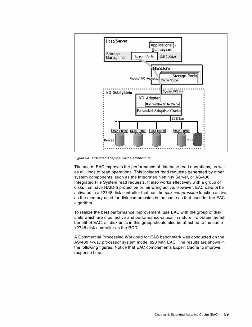
Figure 34. Extended Adaptive Cache architecture
The use of EAC improves the performance of database read operations, as wellas all kinds of read operations. This includes read requests generated by othersystem components, such as the Integrated Netfinity Server, or AS/400Integrated File System read requests. It also works effectively with a group ofdisks that have RAID-5 protection or mirroring active. However, EAC cannot beactivated in a #2748 disk controller that has the disk compression function active,as the memory used for disk compression is the same as that used for the EACalgorithm.
To realize the best performance improvement, use EAC with the group of diskunits which are most active and performance-critical in nature. To obtain the fullbenefit of EAC, all disk units in this group should also be attached to the same#2748 disk controller as the RCD.
A Commercial Processing Workload for EAC benchmark was conducted on theAS/400 4-way processor system model 620 with EAC. The results are shown inthe following figures. Notice that EAC complements Expert Cache to improveresponse time.
Chapter 4. Extended Adaptive Cache (EAC) 59
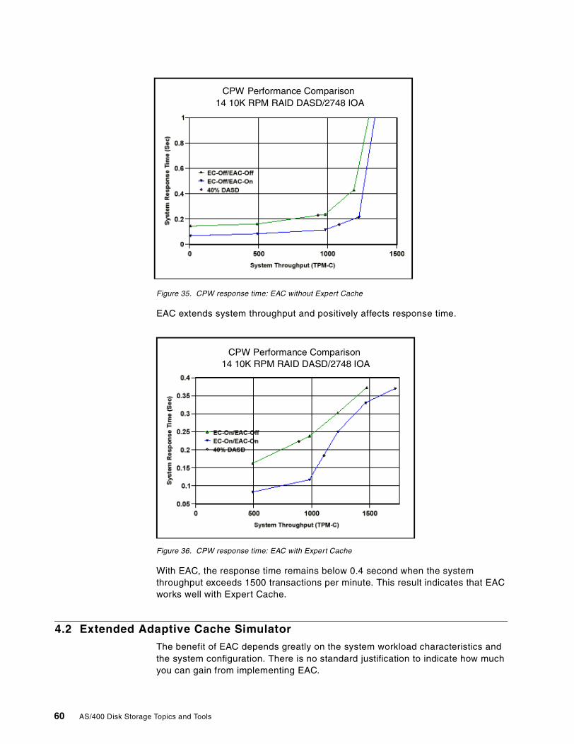
Figure 35. CPW response time: EAC without Expert Cache
EAC extends system throughput and positively affects response time.
Figure 36. CPW response time: EAC with Expert Cache
With EAC, the response time remains below 0.4 second when the systemthroughput exceeds 1500 transactions per minute. This result indicates that EACworks well with Expert Cache.
4.2 Extended Adaptive Cache Simulator
The benefit of EAC depends greatly on the system workload characteristics andthe system configuration. There is no standard justification to indicate how muchyou can gain from implementing EAC.
CPW Performance Comparison14 10K RPM RAID DASD/2748 IOA
CPW Performance Comparison14 10K RPM RAID DASD/2748 IOA
CPW Performance Comparison14 10K RPM RAID DASD/2748 IOA
60 AS/400 Disk Storage Topics and Tools
The overall effectiveness of the EAC is best understood using the EAC Simulator.The EAC Simulator is a function of the #2748 disk controller that collects disk I/Ostatistics for an analysis by the Performance Tool/400 program product(5769-PT1). You can generate a Performance Tool/400 report from the simulatordata to help estimate the performance improvement you can potentially gain fromactivating EAC.
The collected I/O statistics come from the real I/O requests generated from theactual workload in your AS/400 system. The performance report is directlyrelevant to your system setting. You should run the Simulator for at least threehours under a heavily utilized system workload to get the best possibleestimation.
The EAC Simulator operates in the #2748 disk controller itself and uses the samealgorithms that manage the EAC. It is activated through AS/400 ManagementCentral V4R4 Collection Services.
Emulated performance results are shown for an actual workload over time on aper disk basis. The generated report also gives an estimated percent of responsetime improvement for each disk unit.
The EAC Simulator can also be activated by the AS/400 Performance Monitor,which is a component of Performance Tools/400 product.
Activation of the EAC Simulator does not itself improve your system performance.The simulator gathers statistical information for a prediction of performanceimprovement that the EAC could offer if EAC is activated.
The EAC Simulator performance results are reported on a per disk unit basiswithin the Disk Activity section of the Component Report of PerformanceTools/400. The following two fields are updated when the EAC Simulator is active:
• EACS Read (EAC Simulator Percent Read Hits):
This is the percentage of the total reads that are directed to disk that wouldhave instead been satisfied by the RCD.
• EACS Resp (EAC Simulator estimated percent response time improvement):
This is an estimation of how much faster the device would run with the RCDinstalled. This is an approximation, since the Simulator makes basicassumptions about performance parameters that are in place when EAC isactually active. This percentage value represents the amount of reduction youcan expect in the response time that is reported in the Performance Monitor
For instructions on how to run the EAC Simulator and generate a report, visitthe Web site http://www.as400.ibm.com/infocenter. Select V4R4, and click theGO button. Then look under System Administration and Maintenance for atopic of Estimating benefits of Extended Adaptive Cache. A PDF file of theinstruction can also be downloaded from this Web site.
Be sure to apply service pack SF58121 (or later) to Client Access Expresscode before starting the Collection Services. Otherwise, it collects performancedata without EAC statistics.
Note
Chapter 4. Extended Adaptive Cache (EAC) 61
System Report for that disk unit. This projection is valid only when the SystemReport evaluates performance data that matches the characteristics of theperformance data on which this Component Report is based.
Refer to 4.4.1, “A sample performance effect of the Read Cache Device” on page64, for more details.
4.3 Read Cache Device
The Read Cache Device is a volatile device used to temporarily cache data forthe purpose of improving performance. A maximum of one Read Cache Deviceattaches to the #2748 PCI RAID disk controller, and a maximum of three attachper #5065 Storage/PCI Expansion Tower.
The read cache device product feature codes are:
• #4331 for the new #5065 Storage/PCI Expansion Tower on all AS/400e 6xx,Sxx, and 7xx models, except the 600 and the S10
• #6831 for Model 170s, 600, 620, S10, S20, and 720 system units, or Model620, S20, and 720 system unit expansions (#5064/#9364 with #9330 PCIIntegrated Expansion Unit)
Extended Adaptive Cache cannot be used with compression enabled on thesame #2748 PCI RAID Disk Unit Controller IOA. The #2748 IOA is shipped withcompression disabled. Compression is enabled by changing a jumper position onthe IOA. In order for this change to take effect, the system must be IPLed. Referto Figure 37 on page 64 for a view of the #2748 disk controller jumper setting.
For information regarding jumpers and switches, refer to the following Web site:http://publib.boulder.ibm.com/pubs/html/as400/v4r4/ic2924/info/INFOCENT.HTM
Click on each of the following links: System Administration and Maintenance->System maintenance->Storage I/O card modes and jumpers. The sameinformation is provided on your AS/400 Information Center CD set, SK3T-2027.To retrieve this information, click on these same links.
Refer to Table 3 for configuration and physical placement rules for the ReadCache Device.
62 AS/400 Disk Storage Topics and Tools
Table 3. Read Cache Device configuration rules
4.4 The 1.6 GB Read Cache Device
When you decide to use EAC to improve the performance of your application,order the Read Cache Device (RCD), and attach it to the #2748 disk controller.
The RCD is mounted into a disk slot connected through a SCSI bus to thecontroller. The installation of the RCD itself activates EAC. The RCD can beadded into an empty disk slot (or removed), without bringing your AS/400 systemdown, by using the disk concurrent maintenance feature of OS/400.
The cache function covers only the disk units attached under the same #2748disk controller. Depending on your performance requirements, you may needmultiple RCDs when multiple #2748 disk controllers exist in the same system.
Two orderable product feature codes exist for the RCD to be used in your AS/400system:
• #4331 1.6 GB Read Cache Device installs into the #5065 Storage/PCIExpansion Tower on all AS/400e 6XX, SXX, and 7XX models (except the 600and S10).
• #6831 1.6 GB Read Cache Device installs into model 170, 600, 620, S10,S20, and 720 system units, or model 620, S20, and 720 System UnitExpansions (#5064 or #9364 with #9330 PCI Integrated Expansion Unit).
The #2748 disk controller works in either one of the following modes:
• Compression Mode: This mode should only be used when you wish to runIntegrated Hardware Disk Compression. In compression mode, the writecache size available in the controller is 4 MB.
• Enhanced Mode: This mode uses an enhanced write cache size of 26 MB.Enhanced mode also provides support for the EAC through an attachment of aRCD. Without the RCD attached, this mode enables the EAC Simulator.
Enhanced mode is the default setup. No action is required beyond installing theRCD if the card was never switched to compression mode in the past.
Feature code (FC) Description/Rule
#4331 Allowed only in slots D01, D06, D11, D16, D21, D26D31, D36, D46 of FC #5065 PCI Expansion Tower
Uses one DASD slot
Requires FC #2748
1.6 GB capacity
#6831 Not allowed in slot L01 of system unit
Uses one DASD slot
Requires FC #2748
1.6 GB capacity
Chapter 4. Extended Adaptive Cache (EAC) 63
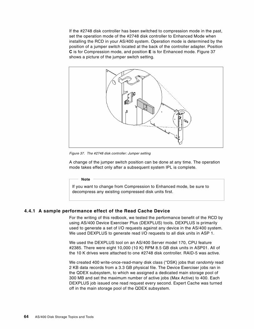
If the #2748 disk controller has been switched to compression mode in the past,set the operation mode of the #2748 disk controller to Enhanced Mode wheninstalling the RCD in your AS/400 system. Operation mode is determined by theposition of a jumper switch located at the back of the controller adapter. PositionC is for Compression mode, and position E is for Enhanced mode. Figure 37shows a picture of the jumper switch setting.
Figure 37. The #2748 disk controller: Jumper setting
A change of the jumper switch position can be done at any time. The operationmode takes effect only after a subsequent system IPL is complete.
4.4.1 A sample performance effect of the Read Cache DeviceFor the writing of this redbook, we tested the performance benefit of the RCD byusing AS/400 Device Exerciser Plus (DEXPLUS) tools. DEXPLUS is primarilyused to generate a set of I/O requests against any device in the AS/400 system.We used DEXPLUS to generate read I/O requests to all disk units in ASP 1.
We used the DEXPLUS tool on an AS/400 Server model 170, CPU feature#2385. There were eight 10,000 (10 K) RPM 8.5 GB disk units in ASP01. All ofthe 10 K drives were attached to one #2748 disk controller. RAID-5 was active.
We created 400 write-once-read-many disk class (*DSK) jobs that randomly read2 KB data records from a 3.3 GB physical file. The Device Exerciser jobs ran inthe QDEX subsystem, to which we assigned a dedicated main storage pool of300 MB and set the maximum number of active jobs (Max Active) to 400. EachDEXPLUS job issued one read request every second. Expert Cache was turnedoff in the main storage pool of the QDEX subsystem.
If you want to change from Compression to Enhanced mode, be sure todecompress any existing compressed disk units first.
Note
64 AS/400 Disk Storage Topics and Tools
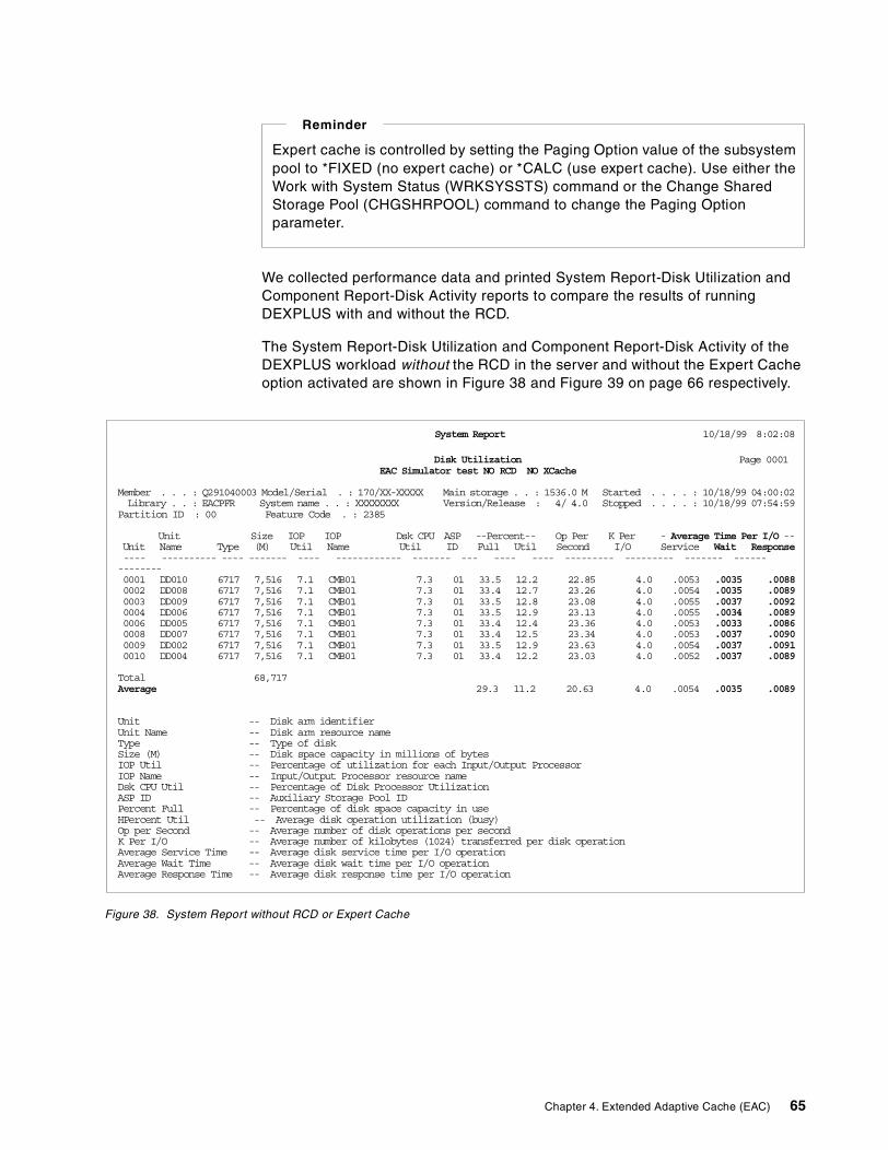
We collected performance data and printed System Report-Disk Utilization andComponent Report-Disk Activity reports to compare the results of runningDEXPLUS with and without the RCD.
The System Report-Disk Utilization and Component Report-Disk Activity of theDEXPLUS workload without the RCD in the server and without the Expert Cacheoption activated are shown in Figure 38 and Figure 39 on page 66 respectively.
Figure 38. System Report without RCD or Expert Cache
Expert cache is controlled by setting the Paging Option value of the subsystempool to *FIXED (no expert cache) or *CALC (use expert cache). Use either theWork with System Status (WRKSYSSTS) command or the Change SharedStorage Pool (CHGSHRPOOL) command to change the Paging Optionparameter.
Reminder
System Report 10/18/99 8:02:08
Disk Utilization Page 0001EAC Simulator test NO RCD NO XCache
Member . . . : Q291040003 Model/Serial . : 170/XX-XXXXX Main storage . . : 1536.0 M Started . . . . : 10/18/99 04:00:02Library . . : EACPFR System name . . : XXXXXXXX Version/Release : 4/ 4.0 Stopped . . . . : 10/18/99 07:54:59
Partition ID : 00 Feature Code . : 2385
Unit Size IOP IOP Dsk CPU ASP --Percent-- Op Per K Per - Average Time Per I/O --Unit Name Type (M) Util Name Util ID Full Util Second I/O Service Wait Response---- ---------- ---- ------- ---- ------------ ------- --- ---- ---- --------- --------- ------- --------------0001 DD010 6717 7,516 7.1 CMB01 7.3 01 33.5 12.2 22.85 4.0 .0053 .0035 .00880002 DD008 6717 7,516 7.1 CMB01 7.3 01 33.4 12.7 23.26 4.0 .0054 .0035 .00890003 DD009 6717 7,516 7.1 CMB01 7.3 01 33.5 12.8 23.08 4.0 .0055 .0037 .00920004 DD006 6717 7,516 7.1 CMB01 7.3 01 33.5 12.9 23.13 4.0 .0055 .0034 .00890006 DD005 6717 7,516 7.1 CMB01 7.3 01 33.4 12.4 23.36 4.0 .0053 .0033 .00860008 DD007 6717 7,516 7.1 CMB01 7.3 01 33.4 12.5 23.34 4.0 .0053 .0037 .00900009 DD002 6717 7,516 7.1 CMB01 7.3 01 33.5 12.9 23.63 4.0 .0054 .0037 .00910010 DD004 6717 7,516 7.1 CMB01 7.3 01 33.4 12.2 23.03 4.0 .0052 .0037 .0089
Total 68,717Average 29.3 11.2 20.63 4.0 .0054 .0035 .0089
Unit -- Disk arm identifierUnit Name -- Disk arm resource nameType -- Type of diskSize (M) -- Disk space capacity in millions of bytesIOP Util -- Percentage of utilization for each Input/Output ProcessorIOP Name -- Input/Output Processor resource nameDsk CPU Util -- Percentage of Disk Processor UtilizationASP ID -- Auxiliary Storage Pool IDPercent Full -- Percentage of disk space capacity in useHPercent Util -- Average disk operation utilization (busy)Op per Second -- Average number of disk operations per secondK Per I/O -- Average number of kilobytes (1024) transferred per disk operationAverage Service Time -- Average disk service time per I/O operationAverage Wait Time -- Average disk wait time per I/O operationAverage Response Time -- Average disk response time per I/O operation
Chapter 4. Extended Adaptive Cache (EAC) 65
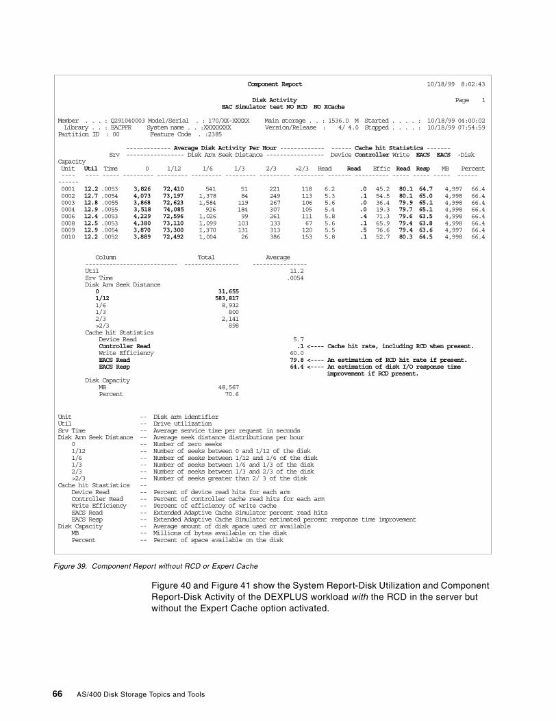
Figure 39. Component Report without RCD or Expert Cache
Figure 40 and Figure 41 show the System Report-Disk Utilization and ComponentReport-Disk Activity of the DEXPLUS workload with the RCD in the server butwithout the Expert Cache option activated.
Component Report 10/18/99 8:02:43
Disk Activity Page 1EAC Simulator test NO RCD NO XCache
Member . . . : Q291040003 Model/Serial . : 170/XX-XXXXX Main storage . . : 1536.0 M Started . . . . : 10/18/99 04:00:02Library . . : EACPFR System name . . :XXXXXXXX Version/Release : 4/ 4.0 Stopped . . . . : 10/18/99 07:54:59
Partition ID : 00 Feature Code . :2385
------------- Average Disk Activity Per Hour ------------- ------ Cache hit Statistics -------Srv ----------------- Disk Arm Seek Distance ----------------- Device Controller Write EACS EACS -Disk
CapacityUnit Util Time 0 1/12 1/6 1/3 2/3 >2/3 Read Read Effic Read Resp MB Percent---- ---- ----- --------- --------- --------- --------- --------- --------- ------- ---------- ----- ----- ----- ------------0001 12.2 .0053 3,826 72,410 541 51 221 118 6.2 .0 45.2 80.1 64.7 4,997 66.40002 12.7 .0054 4,073 73,197 1,378 84 249 113 5.3 .1 54.5 80.1 65.0 4,998 66.40003 12.8 .0055 3,868 72,623 1,584 119 267 106 5.6 .0 36.4 79.9 65.1 4,998 66.40004 12.9 .0055 3,518 74,085 926 184 307 105 5.4 .0 19.3 79.7 65.1 4,998 66.40006 12.4 .0053 4,229 72,596 1,026 99 261 111 5.8 .4 71.3 79.6 63.5 4,998 66.40008 12.5 .0053 4,380 73,110 1,099 103 133 67 5.6 .1 65.9 79.4 63.8 4,998 66.40009 12.9 .0054 3,870 73,300 1,370 131 313 120 5.5 .5 76.6 79.4 63.6 4,997 66.40010 12.2 .0052 3,889 72,492 1,004 26 386 153 5.8 .1 52.7 80.3 64.5 4,998 66.4
Column Total Average--------------------------- ---------------- ----------------Util 11.2Srv Time .0054Disk Arm Seek Distance
0 31,6551/12 583,8171/6 8,9321/3 8002/3 2,141>2/3 898
Cache hit StatisticsDevice Read 5.7Controller Read .1 <---- Cache hit rate, including RCD when present.Write Efficiency 60.0EACS Read 79.8 <---- An estimation of RCD hit rate if present.EACS Resp 64.4 <---- An estimation of disk I/O response time
improvement if RCD present.Disk Capacity
MB 48,567Percent 70.6
Unit -- Disk arm identifierUtil -- Drive utilizationSrv Time -- Average service time per request in secondsDisk Arm Seek Distance -- Average seek distance distributions per hour
0 -- Number of zero seeks1/12 -- Number of seeks between 0 and 1/12 of the disk1/6 -- Number of seeks between 1/12 and 1/6 of the disk1/3 -- Number of seeks between 1/6 and 1/3 of the disk2/3 -- Number of seeks between 1/3 and 2/3 of the disk>2/3 -- Number of seeks greater than 2/ 3 of the disk
Cache hit Stastistics --Device Read -- Percent of device read hits for each armController Read -- Percent of controller cache read hits for each armWrite Efficiency -- Percent of efficiency of write cacheEACS Read -- Extended Adaptive Cache Simulator percent read hitsEACS Resp -- Extended Adaptive Cache Simulator estimated percent response time improvement
Disk Capacity -- Average amount of disk space used or availableMB -- Millions of bytes available on the diskPercent -- Percent of space available on the disk
66 AS/400 Disk Storage Topics and Tools
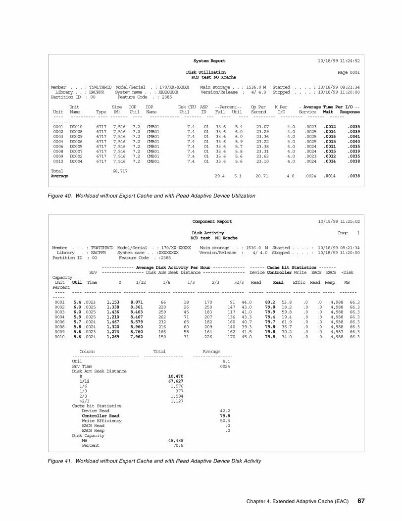
Figure 40. Workload without Expert Cache and with Read Adaptive Device Utilization
Figure 41. Workload without Expert Cache and with Read Adaptive Device Disk Activity
System Report 10/18/99 11:24:52
Disk Utilization Page 0001RCD test NO Xcache
Member . . . : T5WITHRCD Model/Serial . : 170/XX-XXXXX Main storage . . : 1536.0 M Started . . . . : 10/18/99 08:21:34Library . . : EACPFR System name . . : XXXXXXXX Version/Release : 4/ 4.0 Stopped . . . . : 10/18/99 11:20:00
Partition ID : 00 Feature Code . : 2385
Unit Size IOP IOP Dsk CPU ASP --Percent-- Op Per K Per - Average Time Per I/O --Unit Name Type (M) Util Name Util ID Full Util Second I/O Service Wait Response---- ---------- ---- ------- ---- ------------ ------- --- ---- ---- --------- --------- ------- --------------0001 DD010 6717 7,516 7.2 CMB01 7.4 01 33.6 5.4 23.07 4.0 .0023 .0012 .00350002 DD008 6717 7,516 7.2 CMB01 7.4 01 33.6 6.0 23.29 4.0 .0025 .0014 .00390003 DD009 6717 7,516 7.2 CMB01 7.4 01 33.6 6.0 23.36 4.0 .0025 .0016 .00410004 DD006 6717 7,516 7.2 CMB01 7.4 01 33.6 5.9 23.22 4.0 .0025 .0015 .00400006 DD005 6717 7,516 7.2 CMB01 7.4 01 33.6 5.7 23.38 4.0 .0024 .0011 .00350008 DD007 6717 7,516 7.2 CMB01 7.4 01 33.6 5.8 23.31 4.0 .0024 .0015 .00390009 DD002 6717 7,516 7.2 CMB01 7.4 01 33.6 5.6 23.63 4.0 .0023 .0012 .00350010 DD004 6717 7,516 7.2 CMB01 7.4 01 33.6 5.6 23.10 4.0 .0024 .0014 .0038
Total 68,717Average 29.4 5.1 20.71 4.0 .0024 .0014 .0038
Component Report 10/18/99 11:25:02
Disk Activity Page 1RCD test NO Xcache
Member . . . : T5WITHRCD Model/Serial . : 170/XX-XXXXX Main storage . . : 1536.0 M Started . . . . : 10/18/99 08:21:34Library . . : EACPFR System name . . :XXXXXXXX Version/Release : 4/ 4.0 Stopped . . . . : 10/18/99 11:20:00
Partition ID : 00 Feature Code . :2385
------------- Average Disk Activity Per Hour ------------- ------ Cache hit Statistics -------Srv ----------------- Disk Arm Seek Distance ----------------- Device Controller Write EACS EACS -Disk
CapacityUnit Util Time 0 1/12 1/6 1/3 2/3 >2/3 Read Read Effic Read Resp MBPercent---- ---- ----- --------- --------- --------- --------- --------- --------- ------ ---------- ----- ----- ----- ------------0001 5.4 .0023 1,153 8,071 66 18 170 91 44.0 80.2 53.8 .0 .0 4,988 66.30002 6.0 .0025 1,338 8,361 220 26 250 147 43.0 79.8 18.2 .0 .0 4,988 66.30003 6.0 .0025 1,436 8,463 259 45 183 117 41.0 79.9 59.8 .0 .0 4,988 66.30004 5.9 .0025 1,210 8,467 262 71 207 136 43.3 79.4 19.4 .0 .0 4,988 66.30006 5.7 .0024 1,467 8,579 232 65 182 160 40.7 79.7 61.9 .0 .0 4,988 66.30008 5.8 .0024 1,320 8,960 216 60 209 140 39.3 79.8 36.7 .0 .0 4,988 66.30009 5.6 .0023 1,273 8,760 166 58 164 162 41.5 79.8 70.2 .0 .0 4,987 66.30010 5.6 .0024 1,269 7,962 150 31 226 170 45.0 79.8 34.0 .0 .0 4,988 66.3
Column Total Average--------------------------- ---------------- ----------------Util 5.1Srv Time .0024Disk Arm Seek Distance
0 10,4701/12 67,6271/6 1,5761/3 3772/3 1,594>2/3 1,127
Cache hit StatisticsDevice Read 42.2Controller Read 79.8Write Efficiency 50.5EACS Read .0EACS Resp .0
Disk CapacityMB 48,488Percent 70.5
Chapter 4. Extended Adaptive Cache (EAC) 67
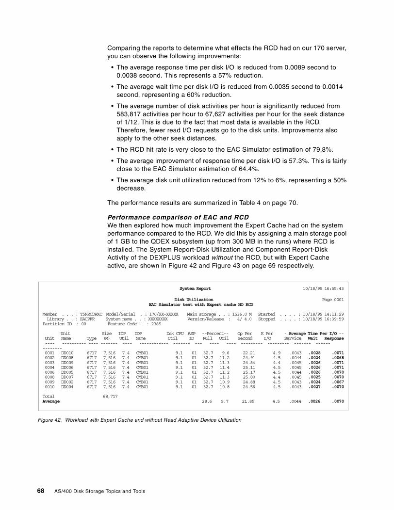
Comparing the reports to determine what effects the RCD had on our 170 server,you can observe the following improvements:
• The average response time per disk I/O is reduced from 0.0089 second to0.0038 second. This represents a 57% reduction.
• The average wait time per disk I/O is reduced from 0.0035 second to 0.0014second, representing a 60% reduction.
• The average number of disk activities per hour is significantly reduced from583,817 activities per hour to 67,627 activities per hour for the seek distanceof 1/12. This is due to the fact that most data is available in the RCD.Therefore, fewer read I/O requests go to the disk units. Improvements alsoapply to the other seek distances.
• The RCD hit rate is very close to the EAC Simulator estimation of 79.8%.
• The average improvement of response time per disk I/O is 57.3%. This is fairlyclose to the EAC Simulator estimation of 64.4%.
• The average disk unit utilization reduced from 12% to 6%, representing a 50%decrease.
The performance results are summarized in Table 4 on page 70.
Performance comparison of EAC and RCDWe then explored how much improvement the Expert Cache had on the systemperformance compared to the RCD. We did this by assigning a main storage poolof 1 GB to the QDEX subsystem (up from 300 MB in the runs) where RCD isinstalled. The System Report-Disk Utilization and Component Report-DiskActivity of the DEXPLUS workload without the RCD, but with Expert Cacheactive, are shown in Figure 42 and Figure 43 on page 69 respectively.
Figure 42. Workload with Expert Cache and without Read Adaptive Device Utilization
System Report 10/18/99 16:55:43
Disk Utilization Page 0001EAC Simulator test with Expert cache NO RCD
Member . . . : T5NRCDWXC Model/Serial . : 170/XX-XXXXX Main storage . . : 1536.0 M Started . . . . : 10/18/99 14:11:29Library . . : EACPFR System name . . : XXXXXXXX Version/Release : 4/ 4.0 Stopped . . . . : 10/18/99 16:39:59
Partition ID : 00 Feature Code . : 2385
Unit Size IOP IOP Dsk CPU ASP --Percent-- Op Per K Per - Average Time Per I/O --Unit Name Type (M) Util Name Util ID Full Util Second I/O Service Wait Response---- ---------- ---- ------- ---- ------------ ------- --- ---- ---- --------- --------- ------- --------------0001 DD010 6717 7,516 7.4 CMB01 9.1 01 32.7 9.6 22.21 4.9 .0043 .0028 .00710002 DD008 6717 7,516 7.4 CMB01 9.1 01 32.7 11.2 24.91 4.5 .0044 .0024 .00680003 DD009 6717 7,516 7.4 CMB01 9.1 01 32.7 11.3 24.84 4.4 .0045 .0026 .00710004 DD006 6717 7,516 7.4 CMB01 9.1 01 32.7 11.4 25.11 4.5 .0045 .0026 .00710006 DD005 6717 7,516 7.4 CMB01 9.1 01 32.7 11.2 25.17 4.5 .0044 .0026 .00700008 DD007 6717 7,516 7.4 CMB01 9.1 01 32.7 11.3 25.00 4.4 .0045 .0025 .00700009 DD002 6717 7,516 7.4 CMB01 9.1 01 32.7 10.9 24.88 4.5 .0043 .0024 .00670010 DD004 6717 7,516 7.4 CMB01 9.1 01 32.7 10.8 24.56 4.5 .0043 .0027 .0070
Total 68,717Average 28.6 9.7 21.85 4.5 .0044 .0026 .0070
68 AS/400 Disk Storage Topics and Tools
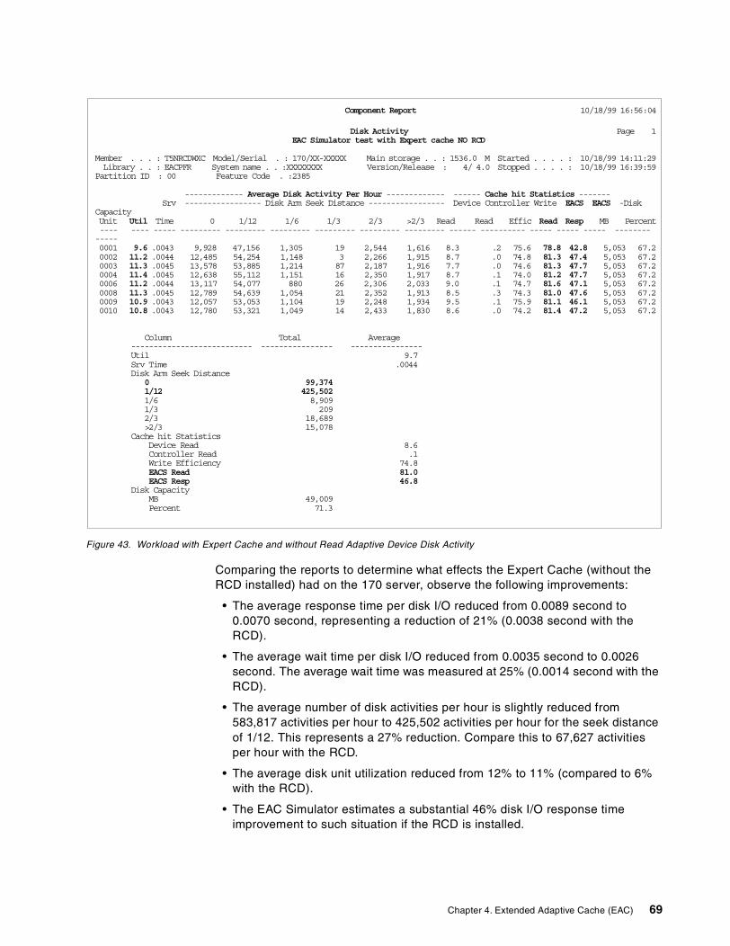
Figure 43. Workload with Expert Cache and without Read Adaptive Device Disk Activity
Comparing the reports to determine what effects the Expert Cache (without theRCD installed) had on the 170 server, observe the following improvements:
• The average response time per disk I/O reduced from 0.0089 second to0.0070 second, representing a reduction of 21% (0.0038 second with theRCD).
• The average wait time per disk I/O reduced from 0.0035 second to 0.0026second. The average wait time was measured at 25% (0.0014 second with theRCD).
• The average number of disk activities per hour is slightly reduced from583,817 activities per hour to 425,502 activities per hour for the seek distanceof 1/12. This represents a 27% reduction. Compare this to 67,627 activitiesper hour with the RCD.
• The average disk unit utilization reduced from 12% to 11% (compared to 6%with the RCD).
• The EAC Simulator estimates a substantial 46% disk I/O response timeimprovement to such situation if the RCD is installed.
Component Report 10/18/99 16:56:04
Disk Activity Page 1EAC Simulator test with Expert cache NO RCD
Member . . . : T5NRCDWXC Model/Serial . : 170/XX-XXXXX Main storage . . : 1536.0 M Started . . . . : 10/18/99 14:11:29Library . . : EACPFR System name . . :XXXXXXXX Version/Release : 4/ 4.0 Stopped . . . . : 10/18/99 16:39:59
Partition ID : 00 Feature Code . :2385
------------- Average Disk Activity Per Hour ------------- ------ Cache hit Statistics -------Srv ----------------- Disk Arm Seek Distance ----------------- Device Controller Write EACS EACS -Disk
CapacityUnit Util Time 0 1/12 1/6 1/3 2/3 >2/3 Read Read Effic Read Resp MB Percent---- ---- ----- --------- --------- --------- --------- --------- --------- ------ ---------- ----- ----- ----- -------------0001 9.6 .0043 9,928 47,156 1,305 19 2,544 1,616 8.3 .2 75.6 78.8 42.8 5,053 67.20002 11.2 .0044 12,485 54,254 1,148 3 2,266 1,915 8.7 .0 74.8 81.3 47.4 5,053 67.20003 11.3 .0045 13,578 53,885 1,214 87 2,187 1,916 7.7 .0 74.6 81.3 47.7 5,053 67.20004 11.4 .0045 12,638 55,112 1,151 16 2,350 1,917 8.7 .1 74.0 81.2 47.7 5,053 67.20006 11.2 .0044 13,117 54,077 880 26 2,306 2,033 9.0 .1 74.7 81.6 47.1 5,053 67.20008 11.3 .0045 12,789 54,639 1,054 21 2,352 1,913 8.5 .3 74.3 81.0 47.6 5,053 67.20009 10.9 .0043 12,057 53,053 1,104 19 2,248 1,934 9.5 .1 75.9 81.1 46.1 5,053 67.20010 10.8 .0043 12,780 53,321 1,049 14 2,433 1,830 8.6 .0 74.2 81.4 47.2 5,053 67.2
Column Total Average--------------------------- ---------------- ----------------Util 9.7Srv Time .0044Disk Arm Seek Distance
0 99,3741/12 425,5021/6 8,9091/3 2092/3 18,689>2/3 15,078
Cache hit StatisticsDevice Read 8.6Controller Read .1Write Efficiency 74.8EACS Read 81.0EACS Resp 46.8
Disk CapacityMB 49,009Percent 71.3
Chapter 4. Extended Adaptive Cache (EAC) 69
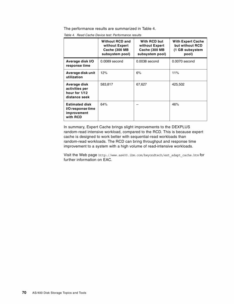
The performance results are summarized in Table 4.
Table 4. Read Cache Device test: Performance results
In summary, Expert Cache brings slight improvements to the DEXPLUSrandom-read intensive workload, compared to the RCD. This is because expertcache is designed to work better with sequential-read workloads thanrandom-read workloads. The RCD can bring throughput and response timeimprovement to a system with a high volume of read-intensive workloads.
Visit the Web page http://www.as400.ibm.com/beyondtech/ext_adapt_cache.htm forfurther information on EAC.
Without RCD andwithout ExpertCache (300 MB
subsystem pool)
With RCD butwithout ExpertCache (300 MB
subsystem pool)
With Expert Cachebut without RCD(1 GB subsystem
pool)
Average disk I/Oresponse time
0.0089 second 0.0038 second 0.0070 second
Average disk unitutilization
12% 6% 11%
Average diskactivities perhour for 1/12distance seek
583,817 67,627 425,502
Estimated diskI/O response timeimprovementwith RCD
64% -- 46%
70 AS/400 Disk Storage Topics and Tools
Part 2. Tools and tips for AS/400 DASD storage management
Part 2 contains topics relative to the organization and management of AS/400disk storage. File system architectures, tools to assess, monitor and manage diskunits, including a process to address expected and unexpected, sudden andgradual growth of information on disk, is provided. Sample code associated withthe WRKDASD tool written for this redbook is found in Appendix D, “WRKDASDsample code” on page 201.
© Copyright IBM Corp. 2000 71

72 AS/400 Disk Storage Topics and Tools
Chapter 5. Extending the Integrated File System with UDFS
The OS/400 User-Defined File System (UDFS) is a storage mechanism thatworks in the same way as the Integrated File System. The UDFS provides ahierarchical directory structure, is optimized for stream file I/O, and supportscase-sensitive names, links, and sockets.
While an Integrated File System directory can be created only in the system ASP,a UDFS and its directory structure can be created in any available ASP. Thismakes it possible for Integrated File System users to make use of theHierarchical Storage Management (HSM) type of ASP balance function inOS/400 V4R4 to manage the Integrated File System stream files, because HSMbalance works only in user ASPs. See 7.2, “The disk balance tool” on page 99, forinformation on ASP balance functions.
In effect, the UDFS was created in OS/400 V3R7 as an extension to the originalIntegrated File System introduced in OS/400 V3R1. If you are familiar with UNIX,the UDFS is similar to what is called the Mounted File System concept.
A UDFS object must always be created in the directory path of \DEV\QASPnn,where “nn” is the ASP number in which UDFS data is stored. Once created, aUDFS object must be mounted onto an existing Integrated File System directorystructure for use. When mounted, the UDFS assumes the target directory pathname. Use this name to access its data.
Use a UDFS in the same manner that you use an Integrated File Systemdirectory. Unmount it when you no longer need access to its data. With the filesystem unmounted, the data is inaccessible from the Integrated File Systemname space. The data remains intact in the UDFS object itself.
You can save and restore UDFS data by OS/400 SAV and RST commands in thesame manner as you do with other Integrated File System components. Refer toOS/400 Integrated File System Introduction, SC41-5711, for more information onUDFS.
5.1 Creating and mounting a UDFS
This section describes a sample procedure to create a UDFS in ASP02 andmount it for use. Two views are presented: Operations Navigator (as the mainapproach) and a Command Language (CL) equivalent (for those who use a 5250session).
Note: In a Windows 95/98 environment, an Integrated File System directory issometimes addressed (that is, referred to) as a folder.
1. To create a UDFS on your AS/400 system, open Operations Navigator andexpand the File Systems -> Integrated File System -> Root -> dev lines, asshown in Figure 44 on page 74.
© Copyright IBM Corp. 2000 73
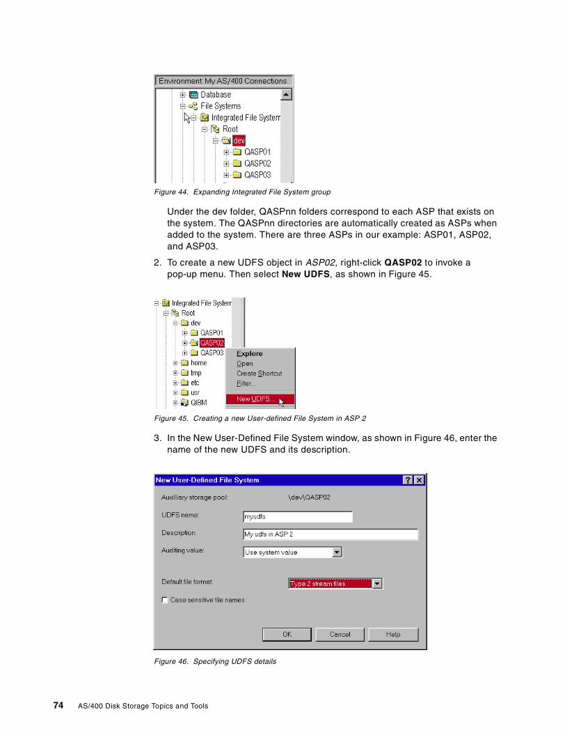
Figure 44. Expanding Integrated File System group
Under the dev folder, QASPnn folders correspond to each ASP that exists onthe system. The QASPnn directories are automatically created as ASPs whenadded to the system. There are three ASPs in our example: ASP01, ASP02,and ASP03.
2. To create a new UDFS object in ASP02, right-click QASP02 to invoke apop-up menu. Then select New UDFS, as shown in Figure 45.
Figure 45. Creating a new User-defined File System in ASP 2
3. In the New User-Defined File System window, as shown in Figure 46, enter thename of the new UDFS and its description.
Figure 46. Specifying UDFS details
74 AS/400 Disk Storage Topics and Tools
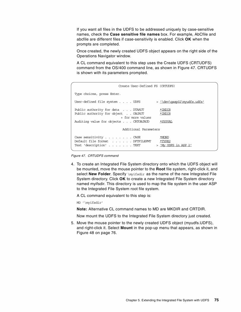
If you want all files in the UDFS to be addressed uniquely by case-sensitivenames, check the Case sensitive file names box. For example, AbCfile andabcfile are different files if case-sensitivity is enabled. Click OK when theprompts are completed.
Once created, the newly created UDFS object appears on the right side of theOperations Navigator window.
A CL command equivalent to this step uses the Create UDFS (CRTUDFS)command from the OS/400 command line, as shown in Figure 47. CRTUDFSis shown with its parameters prompted.
Figure 47. CRTUDFS command
4. To create an Integrated File System directory onto which the UDFS object willbe mounted, move the mouse pointer to the Root file system, right-click it, andselect New Folder. Specify \myifsdir as the name of the new Integrated FileSystem directory. Click OK to create a new Integrated File System directorynamed myifsdir. This directory is used to map the file system in the user ASPto the Integrated File System root file system.
A CL command equivalent to this step is:
MD ’\myifsdir’
Note: Alternative CL command names to MD are MKDIR and CRTDIR.
Now mount the UDFS to the Integrated File System directory just created.
5. Move the mouse pointer to the newly created UDFS object (myudfs.UDFS),and right-click it. Select Mount in the pop-up menu that appears, as shown inFigure 48 on page 76.
Create User-Defined FS (CRTUDFS)
Type choices, press Enter.
User-defined file system . . . . UDFS > '\dev\qasp02\myudfs.udfs'
Public authority for data . . . DTAAUT *INDIRPublic authority for object . . OBJAUT *INDIR
+ for more valuesAuditing value for objects . . . CRTOBJAUD *SYSVAL
Additional Parameters
Case sensitivity . . . . . . . . CASE *MONODefault file format . . . . . . DFTFILEFMT *TYPE2Text 'description' . . . . . . . TEXT > 'My UDFS in ASP 2'
Chapter 5. Extending the Integrated File System with UDFS 75
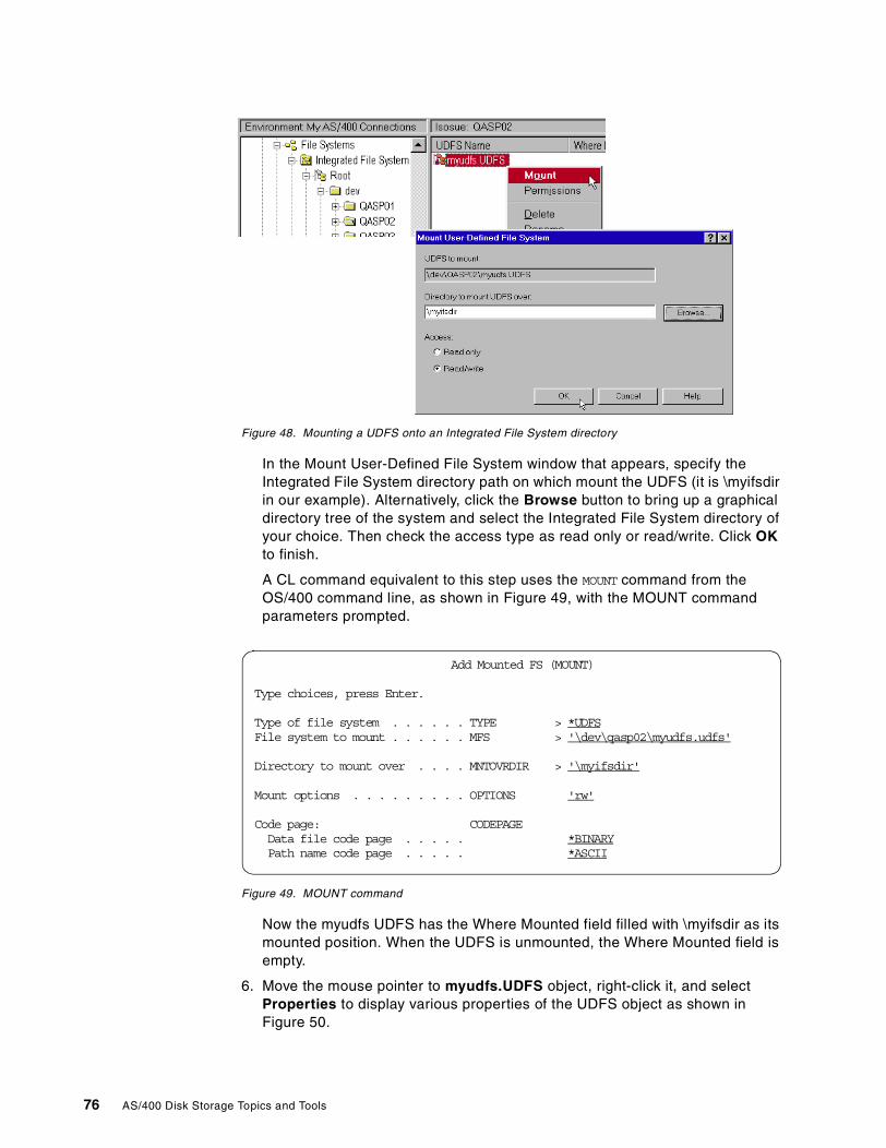
Figure 48. Mounting a UDFS onto an Integrated File System directory
In the Mount User-Defined File System window that appears, specify theIntegrated File System directory path on which mount the UDFS (it is \myifsdirin our example). Alternatively, click the Browse button to bring up a graphicaldirectory tree of the system and select the Integrated File System directory ofyour choice. Then check the access type as read only or read/write. Click OKto finish.
A CL command equivalent to this step uses the MOUNT command from theOS/400 command line, as shown in Figure 49, with the MOUNT commandparameters prompted.
Figure 49. MOUNT command
Now the myudfs UDFS has the Where Mounted field filled with \myifsdir as itsmounted position. When the UDFS is unmounted, the Where Mounted field isempty.
6. Move the mouse pointer to myudfs.UDFS object, right-click it, and selectProperties to display various properties of the UDFS object as shown inFigure 50.
Add Mounted FS (MOUNT)
Type choices, press Enter.
Type of file system . . . . . . TYPE > *UDFSFile system to mount . . . . . . MFS > '\dev\qasp02\myudfs.udfs'
Directory to mount over . . . . MNTOVRDIR > '\myifsdir'
Mount options . . . . . . . . . OPTIONS 'rw'
Code page: CODEPAGEData file code page . . . . . *BINARYPath name code page . . . . . *ASCII
76 AS/400 Disk Storage Topics and Tools
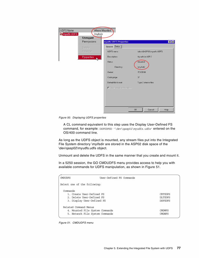
Figure 50. Displaying UDFS properties
A CL command equivalent to this step uses the Display User-Defined FScommand, for example: DSPUDFSD ’\dev\qasp02\myudfs.udfs’ entered on theOS/400 command line.
As long as the UDFS object is mounted, any stream files put into the IntegratedFile System directory \myifsdir are stored in the ASP02 disk space of the\dev\qasp02\myudfs.udfs object.
Unmount and delete the UDFS in the same manner that you create and mount it.
In a 5250 session, the GO CMDUDFS menu provides access to help you withavailable commands for UDFS manipulation, as shown in Figure 51.
Figure 51. CMDUDFS menu
CMDUDFS User-Defined FS Commands
Select one of the following:
Commands1. Create User-Defined FS CRTUDFS2. Delete User-Defined FS DLTUDFS3. Display User-Defined FS DSPUDFS
Related Command Menus4. Mounted File System Commands CMDMFS5. Network File System Commands CMDNFS
Chapter 5. Extending the Integrated File System with UDFS 77
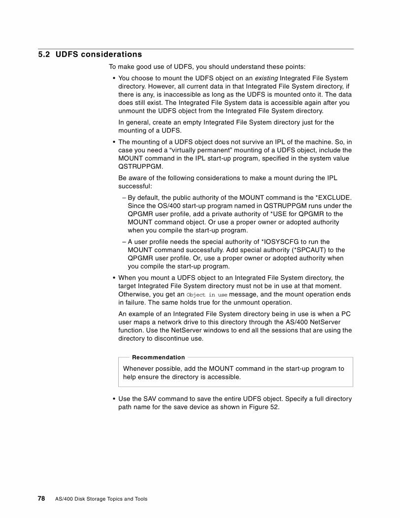
5.2 UDFS considerations
To make good use of UDFS, you should understand these points:
• You choose to mount the UDFS object on an existing Integrated File Systemdirectory. However, all current data in that Integrated File System directory, ifthere is any, is inaccessible as long as the UDFS is mounted onto it. The datadoes still exist. The Integrated File System data is accessible again after youunmount the UDFS object from the Integrated File System directory.
In general, create an empty Integrated File System directory just for themounting of a UDFS.
• The mounting of a UDFS object does not survive an IPL of the machine. So, incase you need a “virtually permanent” mounting of a UDFS object, include theMOUNT command in the IPL start-up program, specified in the system valueQSTRUPPGM.
Be aware of the following considerations to make a mount during the IPLsuccessful:
– By default, the public authority of the MOUNT command is the *EXCLUDE.Since the OS/400 start-up program named in QSTRUPPGM runs under theQPGMR user profile, add a private authority of *USE for QPGMR to theMOUNT command object. Or use a proper owner or adopted authoritywhen you compile the start-up program.
– A user profile needs the special authority of *IOSYSCFG to run theMOUNT command successfully. Add special authority (*SPCAUT) to theQPGMR user profile. Or, use a proper owner or adopted authority whenyou compile the start-up program.
• When you mount a UDFS object to an Integrated File System directory, thetarget Integrated File System directory must not be in use at that moment.Otherwise, you get an Object in use message, and the mount operation endsin failure. The same holds true for the unmount operation.
An example of an Integrated File System directory being in use is when a PCuser maps a network drive to this directory through the AS/400 NetServerfunction. Use the NetServer windows to end all the sessions that are using thedirectory to discontinue use.
• Use the SAV command to save the entire UDFS object. Specify a full directorypath name for the save device as shown in Figure 52.
Whenever possible, add the MOUNT command in the start-up program tohelp ensure the directory is accessible.
Recommendation
78 AS/400 Disk Storage Topics and Tools
Figure 52. Saving UDFS
Only an unmounted UDFS object can be saved directly. Or you can save fromthe Integrated File System directory while the UDFS is mounted. However, inthis case, the UDFS file system information itself is not saved. This means thatalthough you save the Integrated File System directory and its contents, youlose the identity of the source UDFS object. Therefore, a direct save of UDFSis preferred.
With this information, you are now ready to put the UDFS to its practical use formanaging the disk storage of stream files.
For further information on UDFS, refer to the AS/400e Information Center athttp://www.as400.ibm.com/infocenter or the Information Center CD, SK3T-2027,shipped with your AS/400 system.
Save Object (SAV)
Type choices, press Enter.
Device . . . . . . . . . . . . . DEV > '\qsys.lib\tap01.devd'
+ for more values
Objects: OBJName . . . . . . . . . . . . . > '\dev\qasp02\myudfs.udfs'
Include or omit . . . . . . . *INCLUDE+ for more values
Directory subtree . . . . . . . SUBTREE *ALLSave active . . . . . . . . . . SAVACT *NOOutput . . . . . . . . . . . . . OUTPUT > *print
Type of output information . . . INFTYPE *ALL
Chapter 5. Extending the Integrated File System with UDFS 79

80 AS/400 Disk Storage Topics and Tools
Chapter 6. Using the QFILESVR.400 file system
The OS/400 File Server file system (QFILESVR.400) is one of the built-in filesystems of the OS/400 Integrated File System structure. It is a standardcomponent of OS/400. It is designed primarily to enable local jobs from the nativeOS/400 environment to share stream-mode file systems on remote AS/400servers. Although you can also use QFILESVR.400 from a PC environment, youmay not want to do so because there are other, more efficient options available,such as OS/400 NetServer or Network File System (NFS), which let the PCinteract directly with the target AS/400 systems. Refer to The AS/400 NetServerAdvantage, SG24-5196, for more information on NFS.
Applications designed with a capability to access stream files in a distributedenvironment (in addition to DB2/400 database files) can make use of theQFILESVR.400 file system. Two examples of such native advanced applicationsare Domino for AS/400 and SAP R/3 for AS/400. The Licensed Program Productnumbers are 5769-DM1 and 5769-SAP, respectively.
Another example is the native OS/400 archive and retrieval applications thatmake use of optical storage. Objects on an optical storage are stored in a streamfile format. Optical storage is accessed through the Integrated File System. UseQFILESVR.400 to share a direct-attached optical library on one AS/400 systemwith multiple AS/400 systems.
Sharing of QFILESVR.400 is supported in both SNA LU6.2 and TCP/IP networks.This is done by creating a TargetSystemName directly under the QFILESVR.400file system. Specify a path name of\QFILESVR.400\TargetSystemName\Directory\Directory\....\Object to accessobjects on the target system. Each component of the path name can be up to 255characters long. The entire path name can be up to 16 MB in length.
The target system name can be either one of the following:
• A TCP/IP host name, such as itsosys1.ibm.com• An SNA LU 6.2 name such as appn.itsosys1
The target system name is always interpreted as a TCP/IP host name first. If itcannot be resolved to an IP address, it is interpreted as a SNA LU 6.2 name.
An SNA LU 6.2 connection is used if there is an idle session specificallyestablished for use by the LU 6.2 available connection. When establishing an LU6.2 connection, the QFILESVR.400 file system uses an APPC mode named*BLANK. On the target system, a job named QPWFSERV is submitted to theQSERVER subsystem to serve the connection. The user profile running this job isdefined by the communications entry for the *BLANK mode.
For more information about LU 6.2 communications, see APPC Programming,SC41-5443. Refer to OS/400 Integrated File System Introduction, SC41-5711, formore information on QFILESVR.400.
© Copyright IBM Corp. 2000 81
6.1 Configuring QFILESVR.400 in a TCP/IP environment
To prepare for QFILESVR.400 use in a TCP/IP environment, TCP/IP must bestarted on the source and target system. The subsystem QSERVER must beactive in all AS/400 systems involved in the file system sharing. A job namedQPWFSERVSD is automatically activated in QSERVER for QFILESVR.400support.
On systems prior to V4R3, if the subsystem QSERVER is started before TCP/IP,start the program QPWFSERVSD manually. For a convenient use ofQFILESVR.400, modify the OS/400 start up program to start TCP/IP before theQSERVER subsystem is started. Communication links need to be ready amongthe participating systems.
To enable remote file system sharing, create a directory, directly underQFILESVR.400. Use the same name as the TCP/IP host name of the targetsystem to which to connect.
Use Operations Navigator or the OS/400 Make Directory (MD) command tocreate a new folder named HostName under QFILESVR.400. An example of thiscommand is:
MD ‘\QFILESVR.400\HostName’
Note: The target host name must exist either in the local AS/400 host table or inthe domain name server (DNS) known to the local AS/400 system in order for theconnection to be successfully established.
To access the target file system, use matching user IDs and passwords on boththe local (or source) and target systems.
\QFILESVR.400\HostName in the source system represents the entire Root filesystem of the target system. The amount of data you can access depends onyour authority on the target system.
An example of how to use the QFILESVR.400 system to perform disk storagecopy activities is in the following section.
6.2 Copying objects between systems
The CPY command allows you to copy objects within a file system or to anotherfile system that supports the same object format. For example, to copy a streamfile named clref1of4.pdf from a local directory named \usr\mydir to a remotedirectory named \dira on the system ITSOSYS2, the CPY command used isshown in Figure 53.
82 AS/400 Disk Storage Topics and Tools
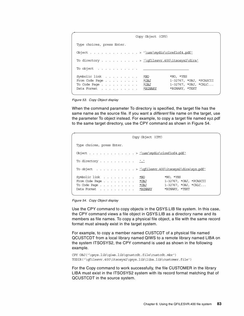
Figure 53. Copy Object display
When the command parameter To directory is specified, the target file has thesame name as the source file. If you want a different file name on the target, usethe parameter To object instead. For example, to copy a target file named xyz.pdfto the same target directory, use the CPY command as shown in Figure 54.
Figure 54. Copy Object display
Use the CPY command to copy objects in the QSYS.LIB file system. In this case,the CPY command views a file object in QSYS.LIB as a directory name and itsmembers as file names. To copy a physical file object, a file with the same recordformat must already exist in the target system.
For example, to copy a member named CUSTCDT of a physical file namedQCUSTCDT from a local library named QIWS to a remote library named LIBA onthe system ITSOSYS2, the CPY command is used as shown in the followingexample.
CPY OBJ('\qsys.lib\qiws.lib\qcustcdt.file\custcdt.mbr')TODIR('\qfilesvr.400\itsosys2\qsys.lib\liba.lib\customer.file')
For the Copy command to work successfully, the file CUSTOMER in the libraryLIBA must exist in the ITSOSYS2 system with its record format matching that ofQCUSTCDT in the source system.
Copy Object (CPY)
Type choices, press Enter.
Object . . . . . . . . . . . . . > '\usr\mydir\clref1of4.pdf'
To directory . . . . . . . . . . > '\qfilesvr.400\itsosys2\dira'
To object . . . . . . . . . . .
Symbolic link . . . . . . . . . *NO *NO, *YESFrom Code Page . . . . . . . . . *OBJ 1-32767, *OBJ, *PCASCIITo Code Page . . . . . . . . . . *OBJ 1-32767, *OBJ, *CALC...Data Format . . . . . . . . . . *BINARY *BINARY, *TEXT
Copy Object (CPY)
Type choices, press Enter.
Object . . . . . . . . . . . . . > '\usr\mydir\clref1of4.pdf'
To directory . . . . . . . . . . '.'
To object . . . . . . . . . . . > '\qfilesvr.400\itsosys2\dira\xyz.pdf'
Symbolic link . . . . . . . . . *NO *NO, *YESFrom Code Page . . . . . . . . . *OBJ 1-32767, *OBJ, *PCASCIITo Code Page . . . . . . . . . . *OBJ 1-32767, *OBJ, *CALC...Data Format . . . . . . . . . . *BINARY *BINARY, *TEXT
Chapter 6. Using the QFILESVR.400 file system 83
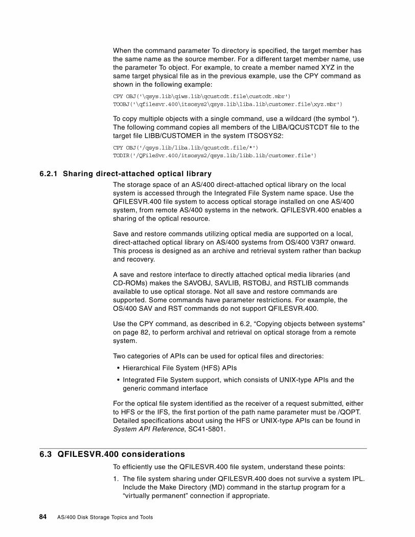
When the command parameter To directory is specified, the target member hasthe same name as the source member. For a different target member name, usethe parameter To object. For example, to create a member named XYZ in thesame target physical file as in the previous example, use the CPY command asshown in the following example:
CPY OBJ('\qsys.lib\qiws.lib\qcustcdt.file\custcdt.mbr')TOOBJ('\qfilesvr.400\itsosys2\qsys.lib\liba.lib\customer.file\xyz.mbr')
To copy multiple objects with a single command, use a wildcard (the symbol *).The following command copies all members of the LIBA/QCUSTCDT file to thetarget file LIBB/CUSTOMER in the system ITSOSYS2:
CPY OBJ('/qsys.lib/liba.lib/qcustcdt.file/*')TODIR('/QFileSvr.400/itsosys2/qsys.lib/libb.lib/customer.file')
6.2.1 Sharing direct-attached optical libraryThe storage space of an AS/400 direct-attached optical library on the localsystem is accessed through the Integrated File System name space. Use theQFILESVR.400 file system to access optical storage installed on one AS/400system, from remote AS/400 systems in the network. QFILESVR.400 enables asharing of the optical resource.
Save and restore commands utilizing optical media are supported on a local,direct-attached optical library on AS/400 systems from OS/400 V3R7 onward.This process is designed as an archive and retrieval system rather than backupand recovery.
A save and restore interface to directly attached optical media libraries (andCD-ROMs) makes the SAVOBJ, SAVLIB, RSTOBJ, and RSTLIB commandsavailable to use optical storage. Not all save and restore commands aresupported. Some commands have parameter restrictions. For example, theOS/400 SAV and RST commands do not support QFILESVR.400.
Use the CPY command, as described in 6.2, “Copying objects between systems”on page 82, to perform archival and retrieval on optical storage from a remotesystem.
Two categories of APIs can be used for optical files and directories:
• Hierarchical File System (HFS) APIs
• Integrated File System support, which consists of UNIX-type APIs and thegeneric command interface
For the optical file system identified as the receiver of a request submitted, eitherto HFS or the IFS, the first portion of the path name parameter must be /QOPT.Detailed specifications about using the HFS or UNIX-type APIs can be found inSystem API Reference, SC41-5801.
6.3 QFILESVR.400 considerations
To efficiently use the QFILESVR.400 file system, understand these points:
1. The file system sharing under QFILESVR.400 does not survive a system IPL.Include the Make Directory (MD) command in the startup program for a“virtually permanent” connection if appropriate.
84 AS/400 Disk Storage Topics and Tools
2. Case-sensitive names depend on the specific file system accessed on thetarget system. For example, case-sensitivity is not supported for objectsearches over the QFILESVR.400 file system.
3. The QFILESVR.400 file system periodically checks every two hours todetermine if there are any connections, which are not used (for example, nofiles opened associated with the connection). Connections that have noactivity for a two-hour period are terminated automatically.
4. The QFILESVR.400 file system does not detect loops. The following pathname is an example of a loop, where “Remote1” is the local system:
/QFileSvr.400/Remote2/QFileSvr.400/Remote1/QFileSvr.400/Remote2/...
When the path name containing a loop is specified, the QFILESVR.400 filesystem returns an error. The error indicates that a time-out has occurred.
5. The QFILESVR.400 file system uses an existing free session to communicateover a SNA LU 6.2 link. Start the mode and establish a session betweensystems to successfully connect QFILESVR.400 to the remote target system.
Chapter 6. Using the QFILESVR.400 file system 85

86 AS/400 Disk Storage Topics and Tools
Chapter 7. OS/400 disk storage management tools
Maintaining an efficient use of AS/400 storage is an essential task and deservingof high priority. Disk storage is an important component of any computer systemas it provides active and permanent access to the data necessary to run abusiness. Efficient disk storage management helps maintain consistent access todata, as well as prevents filling up disk storage before due time.
There are quite a few OS/400 utilities for you as a system administrator to use tomanage AS/400 disk resources in order to maintain its efficient utilization. In thischapter, we describe disk management tools based on OS/400 V4R4. Some ofthe tools discussed are also available in previous releases and noted accordingly.
The tools covered in this chapter are:
• Retrieve Disk Information (RTVDSKINF) and Print Disk Information(PRTDSKINF) commands
• Trace ASP Balance (TRCASPBAL), Start ASP Balance (STRASPBAL) andEnd ASP Balance (ENDASPBAL) commands
• Disk Balance (DSKBAL) command
• Management Central Disk Resource Utilization Monitor
• Start Disk Reorganization (STRDSKRGZ) and End Disk Reorganization(ENDDSKRGZ) commands
Find additional information on these tools at the AS/400 Beyond Technology Webpage at: http://www.as400.ibm.com/beyondtech
7.1 Identifying disk storage consumption of AS/400 objects
One of the most demanding tasks is to maintain efficient use of AS/400 diskstorage, whether the expanding amount of information stored on the AS/400system is due to business growth, or represents information that is not usedfrequently (or at all). After all, some systems are installed with the plannedintention to keep as much information online as practical.
Online data storage “build-up” results when users hesitate deleting information,on the chance that it will be needed again. The hesitation withstands whether thedata is available dynamically or for manual retrieval from offline storage.Clean-up tasks can be enforced, and automated. However, disk storage needscontinue to grow.
For example, copies of main storage dumps are not automatically deleted or“cleaned up”. Each one is only manually deleted when the user (customer orservice center) determines that the problem associated with the dump is solved.This is done by starting the Main Storage Dump Manager service tool. First,select option 2, Work with dump copies, and then select option 4, Delete selecteddump copies. If there is not enough space to hold a new dump copy in auxiliarystorage, the error message Insufficient storage to copy dump is displayed at thebottom of the Main Storage Dump Manager service tool screen. Then, the copyoperation is cancelled. Main storage dumps are not stored entirely on the loadsource. They are stored in files scattered on DASD.
© Copyright IBM Corp. 2000 87
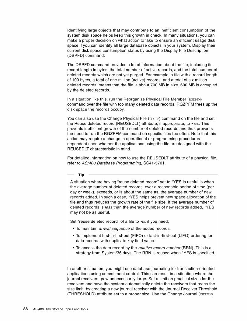
Identifying large objects that may contribute to an inefficient consumption of thesystem disk space helps keep this growth in check. In many situations, you canmake a proper decision on what action to take to ensure an efficient usage diskspace if you can identify all large database objects in your system. Display theircurrent disk space consumption status by using the Display File Description(DSPFD) command.
The DSPFD command provides a lot of information about the file, including itsrecord length in bytes, the total number of active records, and the total number ofdeleted records which are not yet purged. For example, a file with a record lengthof 100 bytes, a total of one million (active) records, and a total of six milliondeleted records, means that the file is about 700 MB in size. 600 MB is occupiedby the deleted records.
In a situation like this, run the Reorganize Physical File Member (RGZPFM)command over the file with too many deleted data records. RGZPFM frees up thedisk space the records occupy.
You can also use the Change Physical File (CHGPF) command on the file and setthe Reuse deleted record (REUSEDLT) attribute, if appropriate, to *YES. Thisprevents inefficient growth of the number of deleted records and thus preventsthe need to run the RGZPFM command on specific files too often. Note that thisaction may require a change in operational or programming proceduresdependent upon whether the applications using the file are designed with theREUSEDLT characteristic in mind.
For detailed information on how to use the REUSEDLT attribute of a physical file,refer to AS/400 Database Programming, SC41-5701.
In another situation, you might use database journaling for transaction-orientedapplications using commitment control. This can result in a situation where thejournal receivers grow unnecessarily large. Set a limit on practical sizes for thereceivers and have the system automatically delete the receivers that reach thesize limit, by creating a new journal receiver with the Journal Receiver Threshold(THRESHOLD) attribute set to a proper size. Use the Change Journal (CHGJRN)
A situation where having “reuse deleted record” set to *YES is useful is whenthe average number of deleted records, over a reasonable period of time (perday or week), exceeds, or is about the same as, the average number of newrecords added. In such a case, *YES helps prevent new space allocation of thefile and thus reduces the growth rate of the file size. If the average number ofdeleted records is less than the average number of new records added, *YESmay not be as useful.
Set “reuse deleted record” of a file to *NO if you need:
• To maintain arrival sequence of the added records.
• To implement first-in-first-out (FIFO) or last-in-first-out (LIFO) ordering fordata records with duplicate key field value.
• To access the data record by the relative record number (RRN). This is astrategy from System/36 days. The RRN is reused when *YES is specified.
Tip
88 AS/400 Disk Storage Topics and Tools
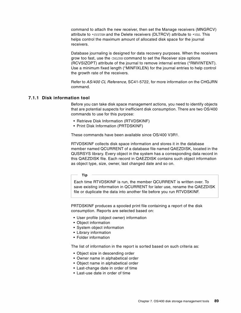
command to attach the new receiver, then set the Manage receivers (MNGRCV)attribute to *SYSTEM and the Delete receivers (DLTRCV) attribute to *YES. Thishelps control the maximum amount of allocated disk space for the journalreceivers.
Database journaling is designed for data recovery purposes. When the receiversgrow too fast, use the CHGJRN command to set the Receiver size options(RCVSIZOPT) attribute of the journal to remove internal entries (*RMVINTENT).Use a minimum fixed length (*MINFIXLEN) for the journal entries to help controlthe growth rate of the receivers.
Refer to AS/400 CL Reference, SC41-5722, for more information on the CHGJRNcommand.
7.1.1 Disk information toolBefore you can take disk space management actions, you need to identify objectsthat are potential suspects for inefficient disk consumption. There are two OS/400commands to use for this purpose:
• Retrieve Disk Information (RTVDSKINF)• Print Disk Information (PRTDSKINF)
These commands have been available since OS/400 V3R1.
RTVDSKINF collects disk space information and stores it in the databasemember named QCURRENT of a database file named QAEZDISK, located in theQUSRSYS library. Every object in the system has a corresponding data record inthis QAEZDISK file. Each record in QAEZDISK contains such object informationas object type, size, owner, last changed date and so on.
PRTDSKINF produces a spooled print file containing a report of the diskconsumption. Reports are selected based on:
• User profile (object owner) information• Object information• System object information• Library information• Folder information
The list of information in the report is sorted based on such criteria as:
• Object size in descending order• Owner name in alphabetical order• Object name in alphabetical order• Last-change date in order of time• Last-use date in order of time
Each time RTVDSKINF is run, the member QCURRENT is written over. Tosave existing information in QCURRENT for later use, rename the QAEZDISKfile or duplicate the data into another file before you run RTVDSKINF.
Tip
Chapter 7. OS/400 disk storage management tools 89
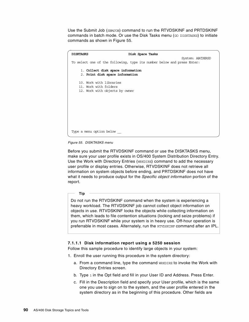
Use the Submit Job (SBMJOB) command to run the RTVDSKINF and PRTDSKINFcommands in batch mode. Or use the Disk Tasks menu (GO DISKTASKS) to initiatecommands as shown in Figure 55.
Figure 55. DISKTASKS menu
Before you submit the RTVDSKINF command or use the DISKTASKS menu,make sure your user profile exists in OS/400 System Distribution Directory Entry.Use the Work with Directory Entries (WRKDIRE) command to add the necessaryuser profile or display entries. Otherwise, RTVDSKINF does not retrieve allinformation on system objects before ending, and PRTDSKINF does not havewhat it needs to produce output for the Specific object information portion of thereport.
7.1.1.1 Disk information report using a 5250 sessionFollow this sample procedure to identify large objects in your system:
1. Enroll the user running this procedure in the system directory:
a. From a command line, type the command WRKDIRE to invoke the Work withDirectory Entries screen.
b. Type 1 in the Opt field and fill in your User ID and Address. Press Enter.
c. Fill in the Description field and specify your User profile, which is the sameone you use to sign on to the system, and the user profile entered in thesystem directory as in the beginning of this procedure. Other fields are
DISKTASKS Disk Space TasksSystem: ABCDERSD
To select one of the following, type its number below and press Enter:
1. Collect disk space information2. Print disk space information
10. Work with libraries11. Work with folders12. Work with objects by owner
Type a menu option below __
Do not run the RTVDSKINF command when the system is experiencing aheavy workload. The RTVDSKINF job cannot collect object information onobjects in use. RTVDSKINF locks the objects while collecting information onthem, which leads to file contention situations (locking and seize problems) ifyou run RTVDSKINF while your system is in heavy use. Off-hour operation ispreferrable in most cases. Alternately, run the RTVDSKINF command after an IPL.
Tip
90 AS/400 Disk Storage Topics and Tools
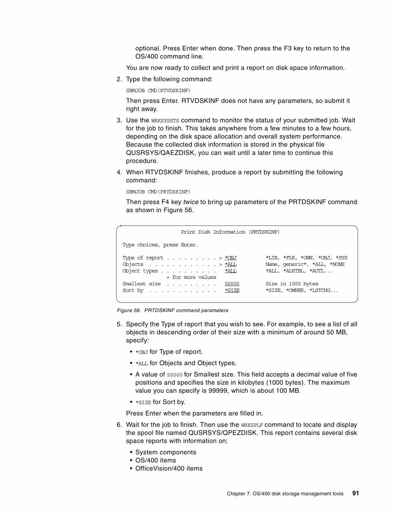
optional. Press Enter when done. Then press the F3 key to return to theOS/400 command line.
You are now ready to collect and print a report on disk space information.
2. Type the following command:
SBMJOB CMD(RTVDSKINF)
Then press Enter. RTVDSKINF does not have any parameters, so submit itright away.
3. Use the WRKSYSSTS command to monitor the status of your submitted job. Waitfor the job to finish. This takes anywhere from a few minutes to a few hours,depending on the disk space allocation and overall system performance.Because the collected disk information is stored in the physical fileQUSRSYS/QAEZDISK, you can wait until a later time to continue thisprocedure.
4. When RTVDSKINF finishes, produce a report by submitting the followingcommand:
SBMJOB CMD(PRTDSKINF)
Then press F4 key twice to bring up parameters of the PRTDSKINF commandas shown in Figure 56.
Figure 56. PRTDSKINF command parameters
5. Specify the Type of report that you wish to see. For example, to see a list of allobjects in descending order of their size with a minimum of around 50 MB,specify:
• *OBJ for Type of report.
• *ALL for Objects and Object types.
• A value of 50000 for Smallest size. This field accepts a decimal value of fivepositions and specifies the size in kilobytes (1000 bytes). The maximumvalue you can specify is 99999, which is about 100 MB.
• *SIZE for Sort by.
Press Enter when the parameters are filled in.
6. Wait for the job to finish. Then use the WRKSPLF command to locate and displaythe spool file named QUSRSYS/QPEZDISK. This report contains several diskspace reports with information on:
• System components• OS/400 items• OfficeVision/400 items
Print Disk Information (PRTDSKINF)
Type choices, press Enter.
Type of report . . . . . . . . . > *OBJ *LIB, *FLR, *OWN, *OBJ, *SYSObjects . . . . . . . . . . . . > *ALL Name, generic*, *ALL, *NONEObject types . . . . . . . . . . *ALL *ALL, *ALRTBL, *AUTL...
+ for more valuesSmallest size . . . . . . . . . 50000 Size in 1000 bytesSort by . . . . . . . . . . . . *SIZE *SIZE, *OWNER, *LSTCHG...
Chapter 7. OS/400 disk storage management tools 91
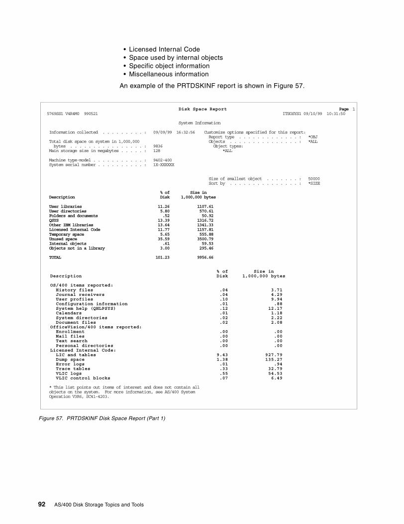
• Licensed Internal Code• Space used by internal objects• Specific object information• Miscellaneous information
An example of the PRTDSKINF report is shown in Figure 57.
Figure 57. PRTDSKINF Disk Space Report (Part 1)
Disk Space Report Page 15769SS1 V4R4M0 990521 ITSOSYS1 09/10/99 10:31:50
System Information
Information collected . . . . . . . . . : 09/09/99 16:32:56 Customize options specified for this report:Report type . . . . . . . . . . . . . : *OBJ
Total disk space on system in 1,000,000 Objects . . . . . . . . . . . . . . . : *ALLbytes . . . . . . . . . . . . . . . . : 9836 Object types:
Main storage size in megabytes . . . . . : 128 *ALL
Machine type-model . . . . . . . . . . . : 9402-400System serial number . . . . . . . . . . : 1X-XXXXXX
Size of smallest object . . . . . . . : 50000Sort by . . . . . . . . . . . . . . . : *SIZE
% of Size inDescription Disk 1,000,000 bytes
User libraries 11.26 1107.61User directories 5.80 570.61Folders and documents .52 50.92QSYS 13.39 1316.72Other IBM libraries 13.64 1341.33Licensed Internal Code 11.77 1157.81Temporary space 5.65 555.88Unused space 35.59 3500.79Internal objects .61 59.53Objects not in a library 3.00 295.46
TOTAL 101.23 9956.66
% of Size inDescription Disk 1,000,000 bytes
OS/400 items reported:History files .04 3.71Journal receivers .04 4.29User profiles .10 9.94Configuration information .01 .88System help (QHLPSYS) .12 12.17Calendars .01 1.18System directories .02 2.22Document files .02 2.08
OfficeVision/400 items reported:Enrollment .00 .00Mail files .00 .00Text search .00 .00Personal directories .00 .00
Licensed Internal Code:LIC and tables 9.43 927.79Dump space 1.38 135.27Error logs .01 .94Trace tables .33 32.79VLIC logs .55 54.53VLIC control blocks .07 6.49
* This list points out items of interest and does not contain allobjects on the system. For more information, see AS/400 SystemOperation V3R6, SC41-4203.
92 AS/400 Disk Storage Topics and Tools
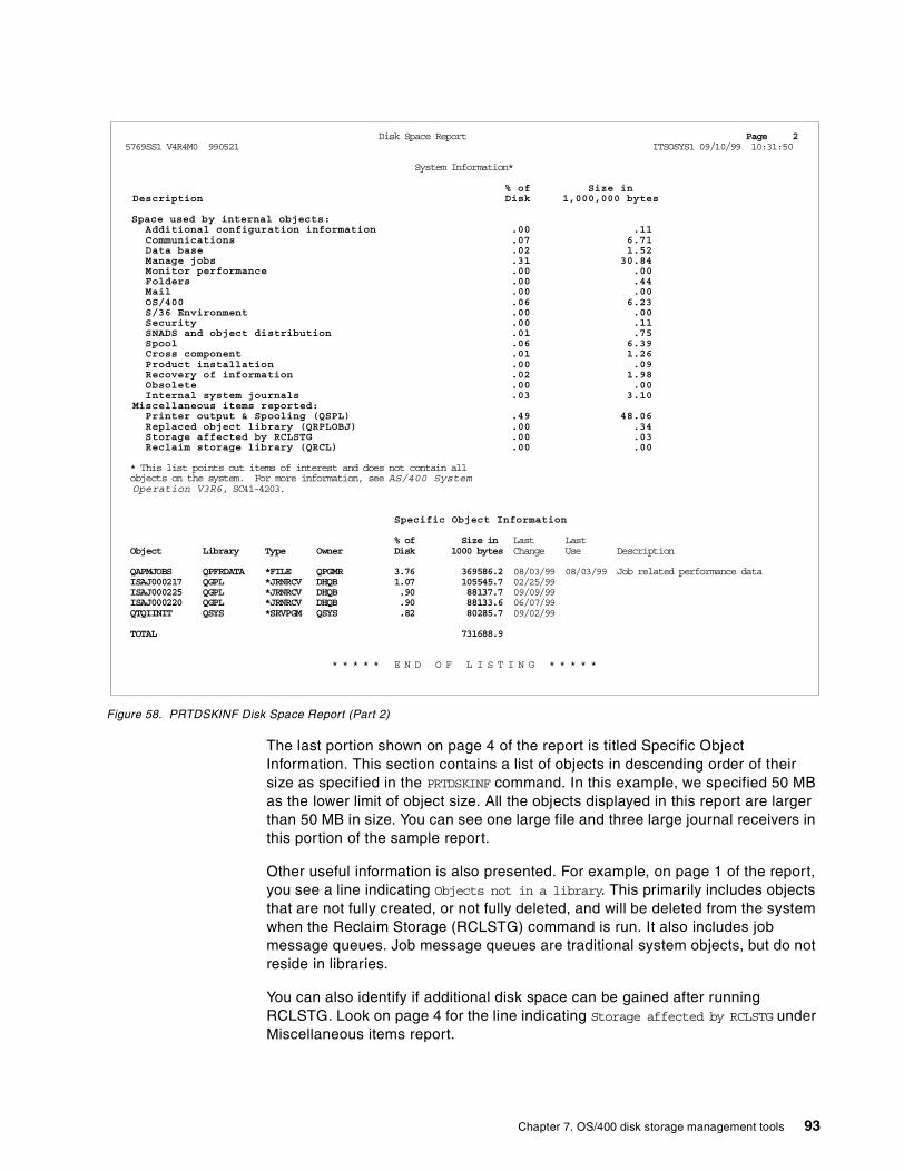
Figure 58. PRTDSKINF Disk Space Report (Part 2)
The last portion shown on page 4 of the report is titled Specific ObjectInformation. This section contains a list of objects in descending order of theirsize as specified in the PRTDSKINF command. In this example, we specified 50 MBas the lower limit of object size. All the objects displayed in this report are largerthan 50 MB in size. You can see one large file and three large journal receivers inthis portion of the sample report.
Other useful information is also presented. For example, on page 1 of the report,you see a line indicating Objects not in a library. This primarily includes objectsthat are not fully created, or not fully deleted, and will be deleted from the systemwhen the Reclaim Storage (RCLSTG) command is run. It also includes jobmessage queues. Job message queues are traditional system objects, but do notreside in libraries.
You can also identify if additional disk space can be gained after runningRCLSTG. Look on page 4 for the line indicating Storage affected by RCLSTG underMiscellaneous items report.
Disk Space Report Page 25769SS1 V4R4M0 990521 ITSOSYS1 09/10/99 10:31:50
System Information*
% of Size inDescription Disk 1,000,000 bytes
Space used by internal objects:Additional configuration information .00 .11Communications .07 6.71Data base .02 1.52Manage jobs .31 30.84Monitor performance .00 .00Folders .00 .44Mail .00 .00OS/400 .06 6.23S/36 Environment .00 .00Security .00 .11SNADS and object distribution .01 .75Spool .06 6.39Cross component .01 1.26Product installation .00 .09Recovery of information .02 1.98Obsolete .00 .00Internal system journals .03 3.10
Miscellaneous items reported:Printer output & Spooling (QSPL) .49 48.06Replaced object library (QRPLOBJ) .00 .34Storage affected by RCLSTG .00 .03Reclaim storage library (QRCL) .00 .00
* This list points out items of interest and does not contain allobjects on the system. For more information, see AS/400 SystemOperation V3R6, SC41-4203.
Specific Object Information
% of Size in Last LastObject Library Type Owner Disk 1000 bytes Change Use Description
QAPMJOBS QPFRDATA *FILE QPGMR 3.76 369586.2 08/03/99 08/03/99 Job related performance dataISAJ000217 QGPL *JRNRCV DHQB 1.07 105545.7 02/25/99ISAJ000225 QGPL *JRNRCV DHQB .90 88137.7 09/09/99ISAJ000220 QGPL *JRNRCV DHQB .90 88133.6 06/07/99QTQIINIT QSYS *SRVPGM QSYS .82 80285.7 09/02/99
TOTAL 731688.9
* * * * * E N D O F L I S T I N G * * * * *
Chapter 7. OS/400 disk storage management tools 93
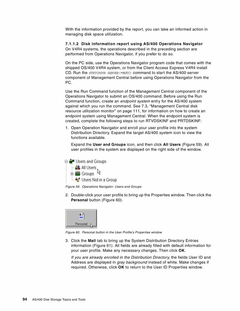
With the information provided by the report, you can take an informed action inmanaging disk space utilization.
7.1.1.2 Disk information report using AS/400 Operations NavigatorOn V4R4 systems, the operations described in the preceding section areperformed from Operations Navigator, if you prefer to do so.
On the PC side, use the Operations Navigator program code that comes with theshipped OS/400 V4R4 system, or from the Client Access Express V4R4 installCD. Run the STRTCPSVR SERVER(*MGTC) command to start the AS/400 servercomponent of Management Central before using Operations Navigator from thePC.
Use the Run Command function of the Management Central component of theOperations Navigator to submit an OS/400 command. Before using the RunCommand function, create an endpoint system entry for the AS/400 systemagainst which you run the command. See 7.3, “Management Central diskresource utilization monitor” on page 111, for information on how to create anendpoint system using Management Central. When the endpoint system iscreated, complete the following steps to run RTVDSKINF and PRTDSKINF:
1. Open Operation Navigator and enroll your user profile into the systemDistribution Directory. Expand the target AS/400 system icon to view thefunctions available.
Expand the User and Groups icon, and then click All Users (Figure 59). Alluser profiles in the system are displayed on the right side of the window.
Figure 59. Operations Navigator: Users and Groups
2. Double-click your user profile to bring up the Properties window. Then click thePersonal button (Figure 60).
Figure 60. Personal button in the User Profile’s Properties window
3. Click the Mail tab to bring up the System Distribution Directory Entriesinformation (Figure 61). All fields are already filled with default information foryour user profile. Make any necessary changes. Then click OK.
If you are already enrolled in the Distribution Directory, the fields User ID andAddress are displayed in gray background instead of white. Make changes ifrequired. Otherwise, click OK to return to the User ID Properties window.
94 AS/400 Disk Storage Topics and Tools
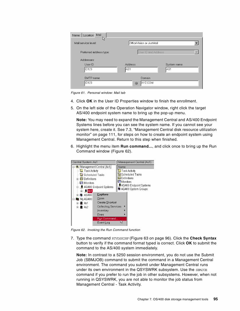
Figure 61. Personal window: Mail tab
4. Click OK in the User ID Properties window to finish the enrollment.
5. On the left side of the Operation Navigator window, right click the targetAS/400 endpoint system name to bring up the pop-up menu.
Note: You may need to expand the Management Central and AS/400 EndpointSystems lines before you can see the system name. If you cannot see yoursystem here, create it. See 7.3, “Management Central disk resource utilizationmonitor” on page 111, for steps on how to create an endpoint system usingManagement Central. Return to this step when finished.
6. Highlight the menu item Run command..., and click once to bring up the RunCommand window (Figure 62).
Figure 62. Invoking the Run Command function
7. Type the command RTVDSKINF (Figure 63 on page 96). Click the Check Syntaxbutton to verify if the command format typed is correct. Click OK to submit thecommand to the AS/400 system immediately.
Note: In contrast to a 5250 session environment, you do not use the SubmitJob (SBMJOB) command to submit the command in a Management Centralenvironment. The command you submit under Management Central runsunder its own environment in the QSYSWRK subsystem. Use the SBMJOB
command if you prefer to run the job in other subsystems. However, when notrunning in QSYSWRK, you are not able to monitor the job status fromManagement Central - Task Activity.
Chapter 7. OS/400 disk storage management tools 95
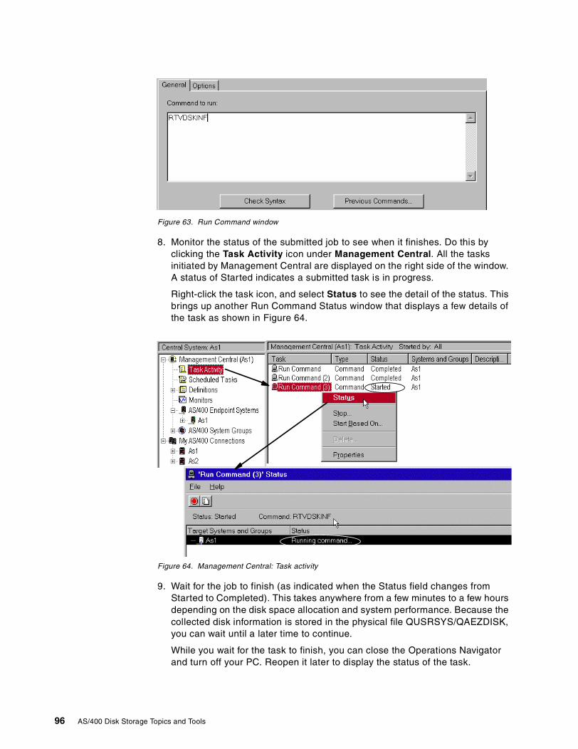
Figure 63. Run Command window
8. Monitor the status of the submitted job to see when it finishes. Do this byclicking the Task Activity icon under Management Central. All the tasksinitiated by Management Central are displayed on the right side of the window.A status of Started indicates a submitted task is in progress.
Right-click the task icon, and select Status to see the detail of the status. Thisbrings up another Run Command Status window that displays a few details ofthe task as shown in Figure 64.
Figure 64. Management Central: Task activity
9. Wait for the job to finish (as indicated when the Status field changes fromStarted to Completed). This takes anywhere from a few minutes to a few hoursdepending on the disk space allocation and system performance. Because thecollected disk information is stored in the physical file QUSRSYS/QAEZDISK,you can wait until a later time to continue.
While you wait for the task to finish, you can close the Operations Navigatorand turn off your PC. Reopen it later to display the status of the task.
96 AS/400 Disk Storage Topics and Tools
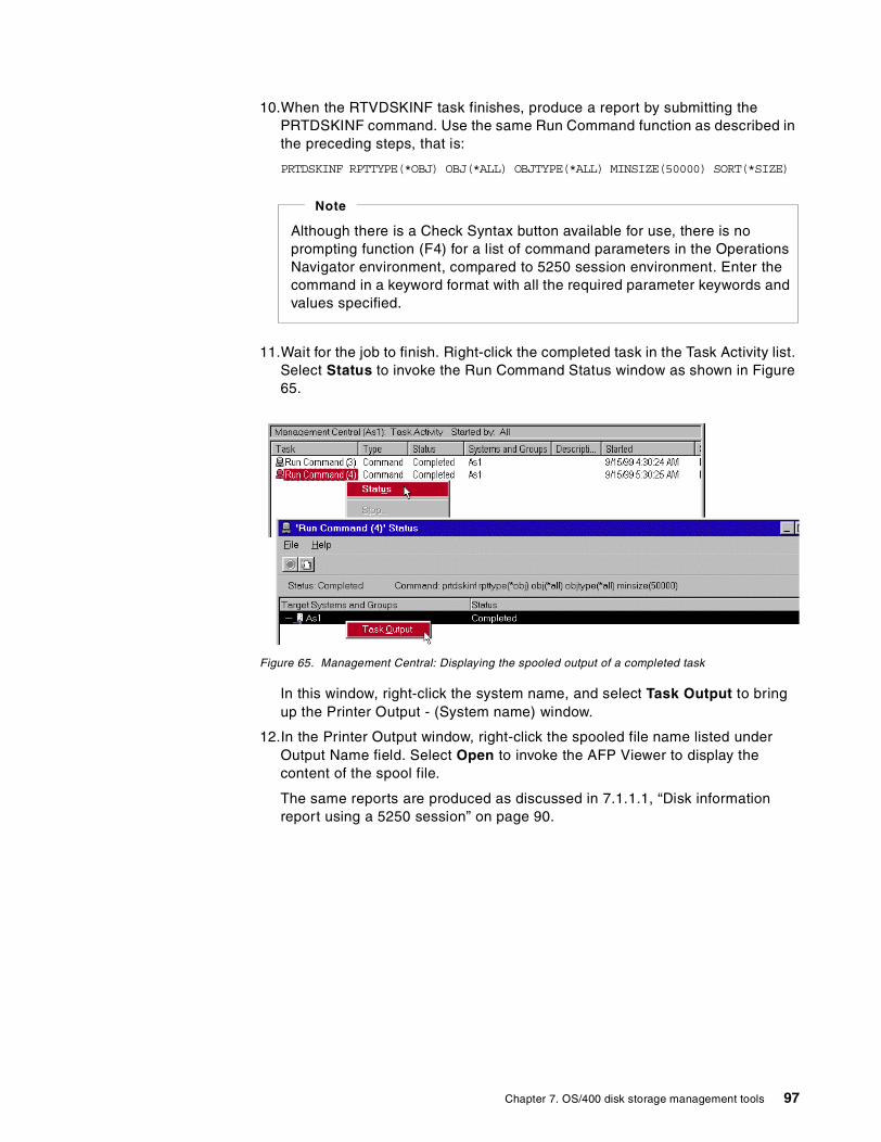
10.When the RTVDSKINF task finishes, produce a report by submitting thePRTDSKINF command. Use the same Run Command function as described inthe preceding steps, that is:
PRTDSKINF RPTTYPE(*OBJ) OBJ(*ALL) OBJTYPE(*ALL) MINSIZE(50000) SORT(*SIZE)
11.Wait for the job to finish. Right-click the completed task in the Task Activity list.Select Status to invoke the Run Command Status window as shown in Figure65.
Figure 65. Management Central: Displaying the spooled output of a completed task
In this window, right-click the system name, and select Task Output to bringup the Printer Output - (System name) window.
12.In the Printer Output window, right-click the spooled file name listed underOutput Name field. Select Open to invoke the AFP Viewer to display thecontent of the spool file.
The same reports are produced as discussed in 7.1.1.1, “Disk informationreport using a 5250 session” on page 90.
Although there is a Check Syntax button available for use, there is noprompting function (F4) for a list of command parameters in the OperationsNavigator environment, compared to 5250 session environment. Enter thecommand in a keyword format with all the required parameter keywords andvalues specified.
Note
Chapter 7. OS/400 disk storage management tools 97
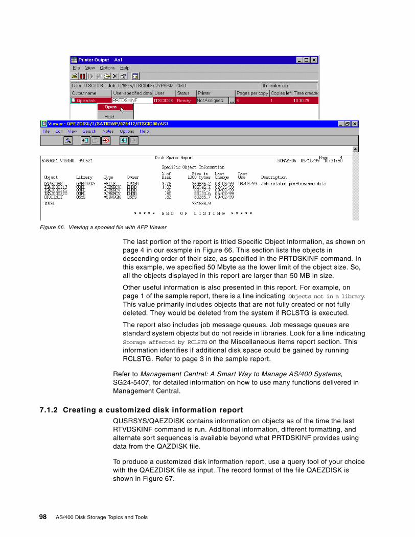
Figure 66. Viewing a spooled file with AFP Viewer
The last portion of the report is titled Specific Object Information, as shown onpage 4 in our example in Figure 66. This section lists the objects indescending order of their size, as specified in the PRTDSKINF command. Inthis example, we specified 50 Mbyte as the lower limit of the object size. So,all the objects displayed in this report are larger than 50 MB in size.
Other useful information is also presented in this report. For example, onpage 1 of the sample report, there is a line indicating Objects not in a library.This value primarily includes objects that are not fully created or not fullydeleted. They would be deleted from the system if RCLSTG is executed.
The report also includes job message queues. Job message queues arestandard system objects but do not reside in libraries. Look for a line indicatingStorage affected by RCLSTG on the Miscellaneous items report section. Thisinformation identifies if additional disk space could be gained by runningRCLSTG. Refer to page 3 in the sample report.
Refer to Management Central: A Smart Way to Manage AS/400 Systems,SG24-5407, for detailed information on how to use many functions delivered inManagement Central.
7.1.2 Creating a customized disk information reportQUSRSYS/QAEZDISK contains information on objects as of the time the lastRTVDSKINF command is run. Additional information, different formatting, andalternate sort sequences is available beyond what PRTDSKINF provides usingdata from the QAZDISK file.
To produce a customized disk information report, use a query tool of your choicewith the QAEZDISK file as input. The record format of the file QAEZDISK isshown in Figure 67.
98 AS/400 Disk Storage Topics and Tools
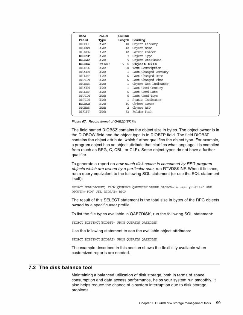
Figure 67. Record format of QAEZDISK file
The field named DIOBSZ contains the object size in bytes. The object owner is inthe DIOBOW field and the object type is in DIOBTP field. The field DIOBATcontains the object attribute, which further qualifies the object type. For example,a program object has an object attribute that clarifies what language it is compiledfrom (such as RPG, C, CBL, or CLP). Some object types do not have a furtherqualifier.
To generate a report on how much disk space is consumed by RPG programobjects which are owned by a particular user, run RTVDSKINF. When it finishes,run a query equivalent to the following SQL statement (or use the SQL statementitself):
SELECT SUM(DIOBSZ) FROM QUSRSYS.QAEZDISK WHERE DIOBOW=’a_user_profile’ ANDDIOBTP=’PGM’ AND DIOBAT=’RPG’
The result of this SELECT statement is the total size in bytes of the RPG objectsowned by a specific user profile.
To list the file types available in QAEZDISK, run the following SQL statement:
SELECT DISTINCT(DIOBTP) FROM QUSRSYS.QAEZDISK
Use the following statement to see the available object attributes:
SELECT DISTINCT(DIOBAT) FROM QUSRSYS.QAEZDISK
The example described in this section shows the flexibility available whencustomized reports are needed.
7.2 The disk balance tool
Maintaining a balanced utilization of disk storage, both in terms of spaceconsumption and data access performance, helps your system run smoothly. Italso helps reduce the chance of a system interruption due to disk storageproblems.
Data_______Field___ ColumnField Type Length HeadingDIOBLI CHAR 10 Object LibraryDIOBNM CHAR 12 Object NameDIPRFL CHAR 12 Parent FolderDIOBTP CHAR 7 Object TypeDIOBAT CHAR 9 Object AttributeDIOBSZ PACKED 15 0 Object SizeDIOBTX CHAR 50 Text DescriptionDICCEN CHAR 1 Last Changed CenturyDICDAT CHAR 6 Last Changed DateDICTIM CHAR 6 Last Changed TimeDIOBUS CHAR 1 Object Use IndicatorDIUCEN CHAR 1 Last Used CenturyDIUDAT CHAR 6 Last Used DateDIUTIM CHAR 6 Last Used TimeDISTIN CHAR 1 Status IndicatorDIOBOW CHAR 10 Object OwnerDIOBAS CHAR 2 Object ASPDIFLPT CHAR 63 Folder Path
Chapter 7. OS/400 disk storage management tools 99
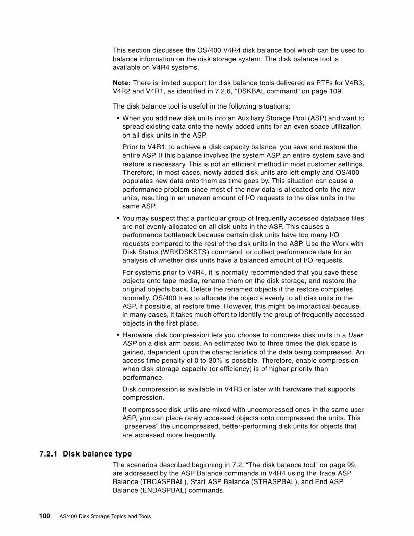
This section discusses the OS/400 V4R4 disk balance tool which can be used tobalance information on the disk storage system. The disk balance tool isavailable on V4R4 systems.
Note: There is limited support for disk balance tools delivered as PTFs for V4R3,V4R2 and V4R1, as identified in 7.2.6, “DSKBAL command” on page 109.
The disk balance tool is useful in the following situations:
• When you add new disk units into an Auxiliary Storage Pool (ASP) and want tospread existing data onto the newly added units for an even space utilizationon all disk units in the ASP.
Prior to V4R1, to achieve a disk capacity balance, you save and restore theentire ASP. If this balance involves the system ASP, an entire system save andrestore is necessary. This is not an efficient method in most customer settings.Therefore, in most cases, newly added disk units are left empty and OS/400populates new data onto them as time goes by. This situation can cause aperformance problem since most of the new data is allocated onto the newunits, resulting in an uneven amount of I/O requests to the disk units in thesame ASP.
• You may suspect that a particular group of frequently accessed database filesare not evenly allocated on all disk units in the ASP. This causes aperformance bottleneck because certain disk units have too many I/Orequests compared to the rest of the disk units in the ASP. Use the Work withDisk Status (WRKDSKSTS) command, or collect performance data for ananalysis of whether disk units have a balanced amount of I/O requests.
For systems prior to V4R4, it is normally recommended that you save theseobjects onto tape media, rename them on the disk storage, and restore theoriginal objects back. Delete the renamed objects if the restore completesnormally. OS/400 tries to allocate the objects evenly to all disk units in theASP, if possible, at restore time. However, this might be impractical because,in many cases, it takes much effort to identify the group of frequently accessedobjects in the first place.
• Hardware disk compression lets you choose to compress disk units in a UserASP on a disk arm basis. An estimated two to three times the disk space isgained, dependent upon the characteristics of the data being compressed. Anaccess time penalty of 0 to 30% is possible. Therefore, enable compressionwhen disk storage capacity (or efficiency) is of higher priority thanperformance.
Disk compression is available in V4R3 or later with hardware that supportscompression.
If compressed disk units are mixed with uncompressed ones in the same userASP, you can place rarely accessed objects onto compressed the units. This“preserves” the uncompressed, better-performing disk units for objects thatare accessed more frequently.
7.2.1 Disk balance typeThe scenarios described beginning in 7.2, “The disk balance tool” on page 99,are addressed by the ASP Balance commands in V4R4 using the Trace ASPBalance (TRCASPBAL), Start ASP Balance (STRASPBAL), and End ASPBalance (ENDASPBAL) commands.
100 AS/400 Disk Storage Topics and Tools
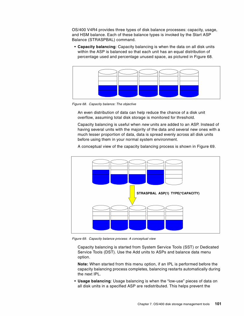
OS/400 V4R4 provides three types of disk balance processes: capacity, usage,and HSM balance. Each of these balance types is invoked by the Start ASPBalance (STRASPBAL) command.
• Capacity balancing: Capacity balancing is when the data on all disk unitswithin the ASP is balanced so that each unit has an equal distribution ofpercentage used and percentage unused space, as pictured in Figure 68.
Figure 68. Capacity balance: The objective
An even distribution of data can help reduce the chance of a disk unitoverflow, assuming total disk storage is monitored for threshold.
Capacity balancing is useful when new units are added to an ASP. Instead ofhaving several units with the majority of the data and several new ones with amuch lesser proportion of data, data is spread evenly across all disk unitsbefore using them in your normal system environment.
A conceptual view of the capacity balancing process is shown in Figure 69.
Figure 69. Capacity balance process: A conceptual view
Capacity balancing is started from System Service Tools (SST) or DedicatedService Tools (DST). Use the Add units to ASPs and balance data menuoption.
Note: When started from this menu option, if an IPL is performed before thecapacity balancing process completes, balancing restarts automatically duringthe next IPL.
• Usage balancing: Usage balancing is when the “low-use” pieces of data onall disk units in a specified ASP are redistributed. This helps prevent the
STRASPBAL ASP(1) TYPE(*CAPACITY)
Chapter 7. OS/400 disk storage management tools 101
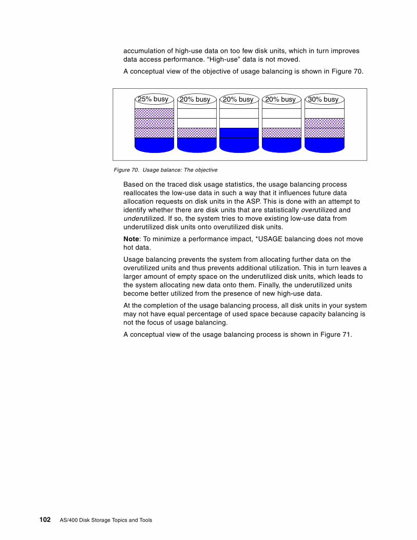
accumulation of high-use data on too few disk units, which in turn improvesdata access performance. “High-use” data is not moved.
A conceptual view of the objective of usage balancing is shown in Figure 70.
Figure 70. Usage balance: The objective
Based on the traced disk usage statistics, the usage balancing processreallocates the low-use data in such a way that it influences future dataallocation requests on disk units in the ASP. This is done with an attempt toidentify whether there are disk units that are statistically overutilized andunderutilized. If so, the system tries to move existing low-use data fromunderutilized disk units onto overutilized disk units.
Note: To minimize a performance impact, *USAGE balancing does not movehot data.
Usage balancing prevents the system from allocating further data on theoverutilized units and thus prevents additional utilization. This in turn leaves alarger amount of empty space on the underutilized disk units, which leads tothe system allocating new data onto them. Finally, the underutilized unitsbecome better utilized from the presence of new high-use data.
At the completion of the usage balancing process, all disk units in your systemmay not have equal percentage of used space because capacity balancing isnot the focus of usage balancing.
A conceptual view of the usage balancing process is shown in Figure 71.
20% busy20% busy25% busy 20% busy 30% busy
102 AS/400 Disk Storage Topics and Tools
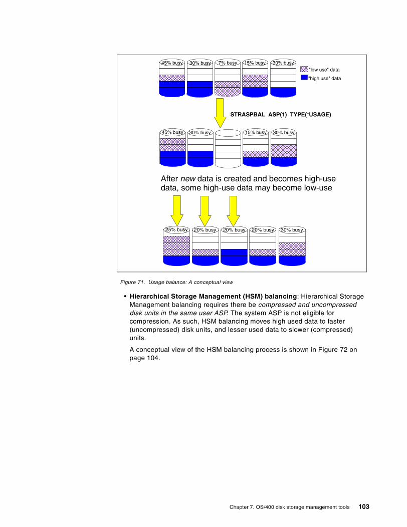
Figure 71. Usage balance: A conceptual view
• Hierarchical Storage Management (HSM) balancing: Hierarchical StorageManagement balancing requires there be compressed and uncompresseddisk units in the same user ASP. The system ASP is not eligible forcompression. As such, HSM balancing moves high used data to faster(uncompressed) disk units, and lesser used data to slower (compressed)units.
A conceptual view of the HSM balancing process is shown in Figure 72 onpage 104.
STRASPBAL ASP(1) TYPE(*USAGE)
30% busy 7% busy45% busy 30% busy15% busy
"high use" data
"low use" data
15% busy45% busy 30% busy 30% busy
After new data is created and becomes high-usedata, some high-use data may become low-use
20% busy20% busy25% busy 20% busy 30% busy
Chapter 7. OS/400 disk storage management tools 103
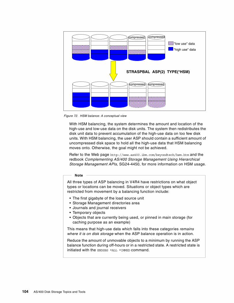
Figure 72. HSM balance: A conceptual view
With HSM balancing, the system determines the amount and location of thehigh-use and low-use data on the disk units. The system then redistributes thedisk unit data to prevent accumulation of the high-use data on too few diskunits. With HSM balancing, the user ASP should contain a sufficient amount ofuncompressed disk space to hold all the high-use data that HSM balancingmoves onto. Otherwise, the goal might not be achieved.
Refer to the Web page http://www.as400.ibm.com/beyondtech/hsm.htm and theredbook Complementing AS/400 Storage Management Using HierarchicalStorage Management APIs, SG24-4450, for more information on HSM usage.
STRASPBAL ASP(2) TYPE(*HSM)
compressed compressed
compressed compressed
"high use" data
"low use" data
All three types of ASP balancing in V4R4 have restrictions on what objecttypes or locations can be moved. Situations or object types which arerestricted from movement by a balancing function include:
• The first gigabyte of the load source unit• Storage Management directories area• Journals and journal receivers• Temporary objects• Objects that are currently being used, or pinned in main storage (for
caching purpose as an example)
This means that high-use data which falls into these categories remainswhere it is on disk storage when the ASP balance operation is in action.
Reduce the amount of unmovable objects to a minimum by running the ASPbalance function during off-hours or in a restricted state. A restricted state isinitiated with the ENDSBS *ALL *IMMED command.
Note
104 AS/400 Disk Storage Topics and Tools
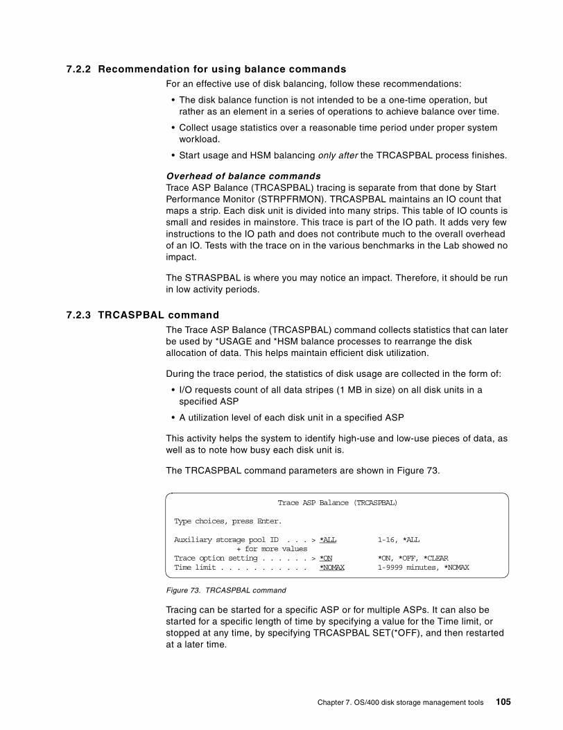
7.2.2 Recommendation for using balance commandsFor an effective use of disk balancing, follow these recommendations:
• The disk balance function is not intended to be a one-time operation, butrather as an element in a series of operations to achieve balance over time.
• Collect usage statistics over a reasonable time period under proper systemworkload.
• Start usage and HSM balancing only after the TRCASPBAL process finishes.
Overhead of balance commandsTrace ASP Balance (TRCASPBAL) tracing is separate from that done by StartPerformance Monitor (STRPFRMON). TRCASPBAL maintains an IO count thatmaps a strip. Each disk unit is divided into many strips. This table of IO counts issmall and resides in mainstore. This trace is part of the IO path. It adds very fewinstructions to the IO path and does not contribute much to the overall overheadof an IO. Tests with the trace on in the various benchmarks in the Lab showed noimpact.
The STRASPBAL is where you may notice an impact. Therefore, it should be runin low activity periods.
7.2.3 TRCASPBAL commandThe Trace ASP Balance (TRCASPBAL) command collects statistics that can laterbe used by *USAGE and *HSM balance processes to rearrange the diskallocation of data. This helps maintain efficient disk utilization.
During the trace period, the statistics of disk usage are collected in the form of:
• I/O requests count of all data stripes (1 MB in size) on all disk units in aspecified ASP
• A utilization level of each disk unit in a specified ASP
This activity helps the system to identify high-use and low-use pieces of data, aswell as to note how busy each disk unit is.
The TRCASPBAL command parameters are shown in Figure 73.
Figure 73. TRCASPBAL command
Tracing can be started for a specific ASP or for multiple ASPs. It can also bestarted for a specific length of time by specifying a value for the Time limit, orstopped at any time, by specifying TRCASPBAL SET(*OFF), and then restartedat a later time.
Trace ASP Balance (TRCASPBAL)
Type choices, press Enter.
Auxiliary storage pool ID . . . > *ALL 1-16, *ALL+ for more values
Trace option setting . . . . . . > *ON *ON, *OFF, *CLEARTime limit . . . . . . . . . . . *NOMAX 1-9999 minutes, *NOMAX
Chapter 7. OS/400 disk storage management tools 105
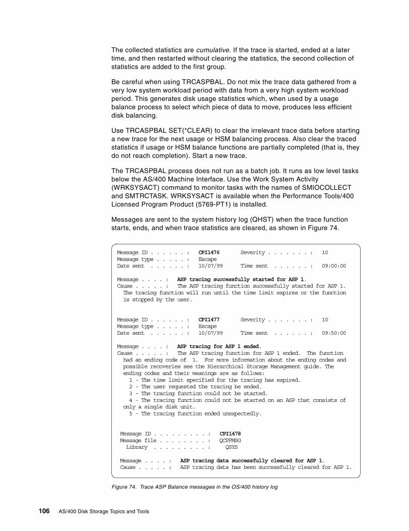
The collected statistics are cumulative. If the trace is started, ended at a latertime, and then restarted without clearing the statistics, the second collection ofstatistics are added to the first group.
Be careful when using TRCASPBAL. Do not mix the trace data gathered from avery low system workload period with data from a very high system workloadperiod. This generates disk usage statistics which, when used by a usagebalance process to select which piece of data to move, produces less efficientdisk balancing.
Use TRCASPBAL SET(*CLEAR) to clear the irrelevant trace data before startinga new trace for the next usage or HSM balancing process. Also clear the tracedstatistics if usage or HSM balance functions are partially completed (that is, theydo not reach completion). Start a new trace.
The TRCASPBAL process does not run as a batch job. It runs as low level tasksbelow the AS/400 Machine Interface. Use the Work System Activity(WRKSYSACT) command to monitor tasks with the names of SMIOCOLLECTand SMTRCTASK. WRKSYSACT is available when the Performance Tools/400Licensed Program Product (5769-PT1) is installed.
Messages are sent to the system history log (QHST) when the trace functionstarts, ends, and when trace statistics are cleared, as shown in Figure 74.
Figure 74. Trace ASP Balance messages in the OS/400 history log
Message ID . . . . . . : CPI1476 Severity . . . . . . . : 10Message type . . . . . : EscapeDate sent . . . . . . : 10/07/99 Time sent . . . . . . : 09:00:00
Message . . . . : ASP tracing successfully started for ASP 1.Cause . . . . . : The ASP tracing function successfully started for ASP 1.The tracing function will run until the time limit expires or the functionis stopped by the user.
Message ID . . . . . . : CPI1477 Severity . . . . . . . : 10Message type . . . . . : EscapeDate sent . . . . . . : 10/07/99 Time sent . . . . . . : 09:50:00
Message . . . . : ASP tracing for ASP 1 ended.Cause . . . . . : The ASP tracing function for ASP 1 ended. The functionhad an ending code of 1. For more information about the ending codes andpossible recoveries see the Hierarchical Storage Management guide. Theending codes and their meanings are as follows:1 - The time limit specified for the tracing has expired.2 - The user requested the tracing be ended.3 - The tracing function could not be started.4 - The tracing function could not be started on an ASP that consists of
only a single disk unit.5 - The tracing function ended unexpectedly.
Message ID . . . . . . . . . : CPI1478Message file . . . . . . . . : QCPFMSGLibrary . . . . . . . . . : QSYS
Message . . . . : ASP tracing data successfully cleared for ASP 1.Cause . . . . . : ASP tracing data has been successfully cleared for ASP 1.
106 AS/400 Disk Storage Topics and Tools
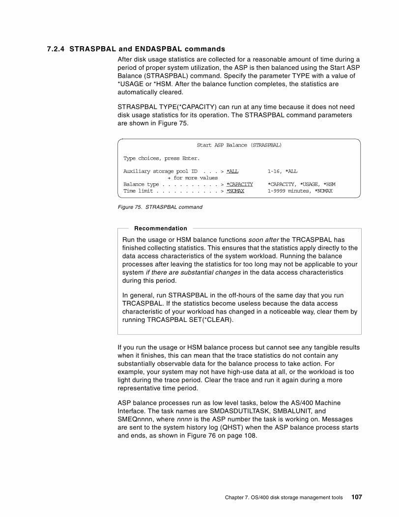
7.2.4 STRASPBAL and ENDASPBAL commandsAfter disk usage statistics are collected for a reasonable amount of time during aperiod of proper system utilization, the ASP is then balanced using the Start ASPBalance (STRASPBAL) command. Specify the parameter TYPE with a value of*USAGE or *HSM. After the balance function completes, the statistics areautomatically cleared.
STRASPBAL TYPE(*CAPACITY) can run at any time because it does not needdisk usage statistics for its operation. The STRASPBAL command parametersare shown in Figure 75.
Figure 75. STRASPBAL command
If you run the usage or HSM balance process but cannot see any tangible resultswhen it finishes, this can mean that the trace statistics do not contain anysubstantially observable data for the balance process to take action. Forexample, your system may not have high-use data at all, or the workload is toolight during the trace period. Clear the trace and run it again during a morerepresentative time period.
ASP balance processes run as low level tasks, below the AS/400 MachineInterface. The task names are SMDASDUTILTASK, SMBALUNIT, andSMEQnnnn, where nnnn is the ASP number the task is working on. Messagesare sent to the system history log (QHST) when the ASP balance process startsand ends, as shown in Figure 76 on page 108.
Start ASP Balance (STRASPBAL)
Type choices, press Enter.
Auxiliary storage pool ID . . . > *ALL 1-16, *ALL+ for more values
Balance type . . . . . . . . . . > *CAPACITY *CAPACITY, *USAGE, *HSMTime limit . . . . . . . . . . . > *NOMAX 1-9999 minutes, *NOMAX
Run the usage or HSM balance functions soon after the TRCASPBAL hasfinished collecting statistics. This ensures that the statistics apply directly to thedata access characteristics of the system workload. Running the balanceprocesses after leaving the statistics for too long may not be applicable to yoursystem if there are substantial changes in the data access characteristicsduring this period.
In general, run STRASPBAL in the off-hours of the same day that you runTRCASPBAL. If the statistics become useless because the data accesscharacteristic of your workload has changed in a noticeable way, clear them byrunning TRCASPBAL SET(*CLEAR).
Recommendation
Chapter 7. OS/400 disk storage management tools 107
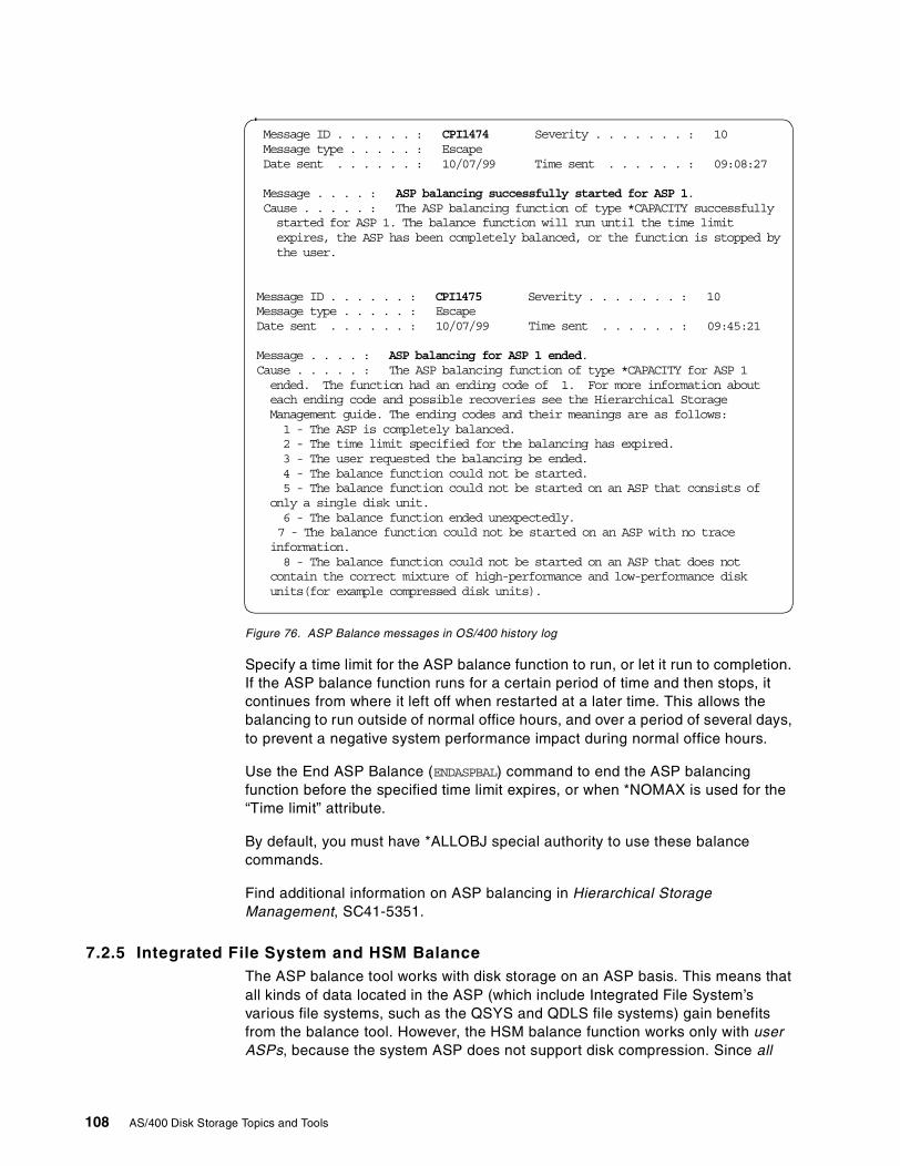
Figure 76. ASP Balance messages in OS/400 history log
Specify a time limit for the ASP balance function to run, or let it run to completion.If the ASP balance function runs for a certain period of time and then stops, itcontinues from where it left off when restarted at a later time. This allows thebalancing to run outside of normal office hours, and over a period of several days,to prevent a negative system performance impact during normal office hours.
Use the End ASP Balance (ENDASPBAL) command to end the ASP balancingfunction before the specified time limit expires, or when *NOMAX is used for the“Time limit” attribute.
By default, you must have *ALLOBJ special authority to use these balancecommands.
Find additional information on ASP balancing in Hierarchical StorageManagement, SC41-5351.
7.2.5 Integrated File System and HSM BalanceThe ASP balance tool works with disk storage on an ASP basis. This means thatall kinds of data located in the ASP (which include Integrated File System’svarious file systems, such as the QSYS and QDLS file systems) gain benefitsfrom the balance tool. However, the HSM balance function works only with userASPs, because the system ASP does not support disk compression. Since all
Message ID . . . . . . : CPI1474 Severity . . . . . . . : 10Message type . . . . . : EscapeDate sent . . . . . . : 10/07/99 Time sent . . . . . . : 09:08:27
Message . . . . : ASP balancing successfully started for ASP 1.Cause . . . . . : The ASP balancing function of type *CAPACITY successfullystarted for ASP 1. The balance function will run until the time limitexpires, the ASP has been completely balanced, or the function is stopped bythe user.
Message ID . . . . . . : CPI1475 Severity . . . . . . . : 10Message type . . . . . : EscapeDate sent . . . . . . : 10/07/99 Time sent . . . . . . : 09:45:21
Message . . . . : ASP balancing for ASP 1 ended.Cause . . . . . : The ASP balancing function of type *CAPACITY for ASP 1ended. The function had an ending code of 1. For more information abouteach ending code and possible recoveries see the Hierarchical StorageManagement guide. The ending codes and their meanings are as follows:1 - The ASP is completely balanced.2 - The time limit specified for the balancing has expired.3 - The user requested the balancing be ended.4 - The balance function could not be started.5 - The balance function could not be started on an ASP that consists of
only a single disk unit.6 - The balance function ended unexpectedly.7 - The balance function could not be started on an ASP with no traceinformation.8 - The balance function could not be started on an ASP that does not
contain the correct mixture of high-performance and low-performance diskunits(for example compressed disk units).
108 AS/400 Disk Storage Topics and Tools
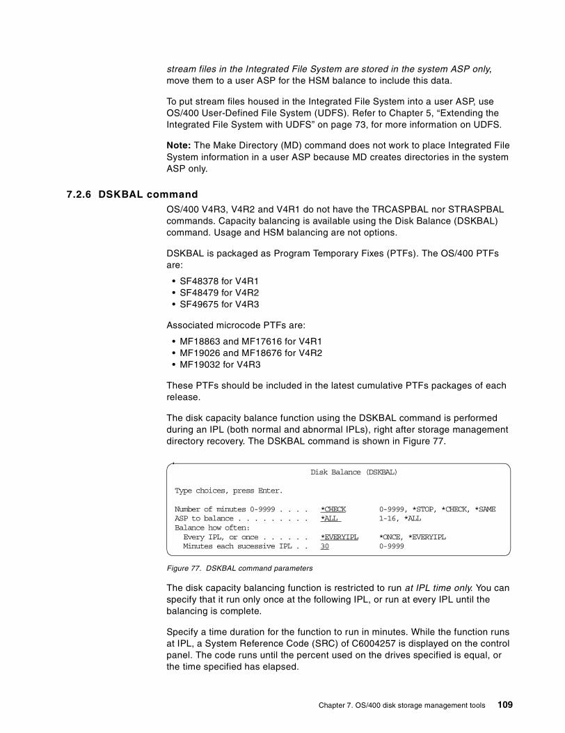
stream files in the Integrated File System are stored in the system ASP only,move them to a user ASP for the HSM balance to include this data.
To put stream files housed in the Integrated File System into a user ASP, useOS/400 User-Defined File System (UDFS). Refer to Chapter 5, “Extending theIntegrated File System with UDFS” on page 73, for more information on UDFS.
Note: The Make Directory (MD) command does not work to place Integrated FileSystem information in a user ASP because MD creates directories in the systemASP only.
7.2.6 DSKBAL commandOS/400 V4R3, V4R2 and V4R1 do not have the TRCASPBAL nor STRASPBALcommands. Capacity balancing is available using the Disk Balance (DSKBAL)command. Usage and HSM balancing are not options.
DSKBAL is packaged as Program Temporary Fixes (PTFs). The OS/400 PTFsare:
• SF48378 for V4R1• SF48479 for V4R2• SF49675 for V4R3
Associated microcode PTFs are:
• MF18863 and MF17616 for V4R1• MF19026 and MF18676 for V4R2• MF19032 for V4R3
These PTFs should be included in the latest cumulative PTFs packages of eachrelease.
The disk capacity balance function using the DSKBAL command is performedduring an IPL (both normal and abnormal IPLs), right after storage managementdirectory recovery. The DSKBAL command is shown in Figure 77.
Figure 77. DSKBAL command parameters
The disk capacity balancing function is restricted to run at IPL time only. You canspecify that it run only once at the following IPL, or run at every IPL until thebalancing is complete.
Specify a time duration for the function to run in minutes. While the function runsat IPL, a System Reference Code (SRC) of C6004257 is displayed on the controlpanel. The code runs until the percent used on the drives specified is equal, orthe time specified has elapsed.
Disk Balance (DSKBAL)
Type choices, press Enter.
Number of minutes 0-9999 . . . . *CHECK 0-9999, *STOP, *CHECK, *SAMEASP to balance . . . . . . . . . *ALL 1-16, *ALLBalance how often:Every IPL, or once . . . . . . *EVERYIPL *ONCE, *EVERYIPLMinutes each sucessive IPL . . 30 0-9999
Chapter 7. OS/400 disk storage management tools 109
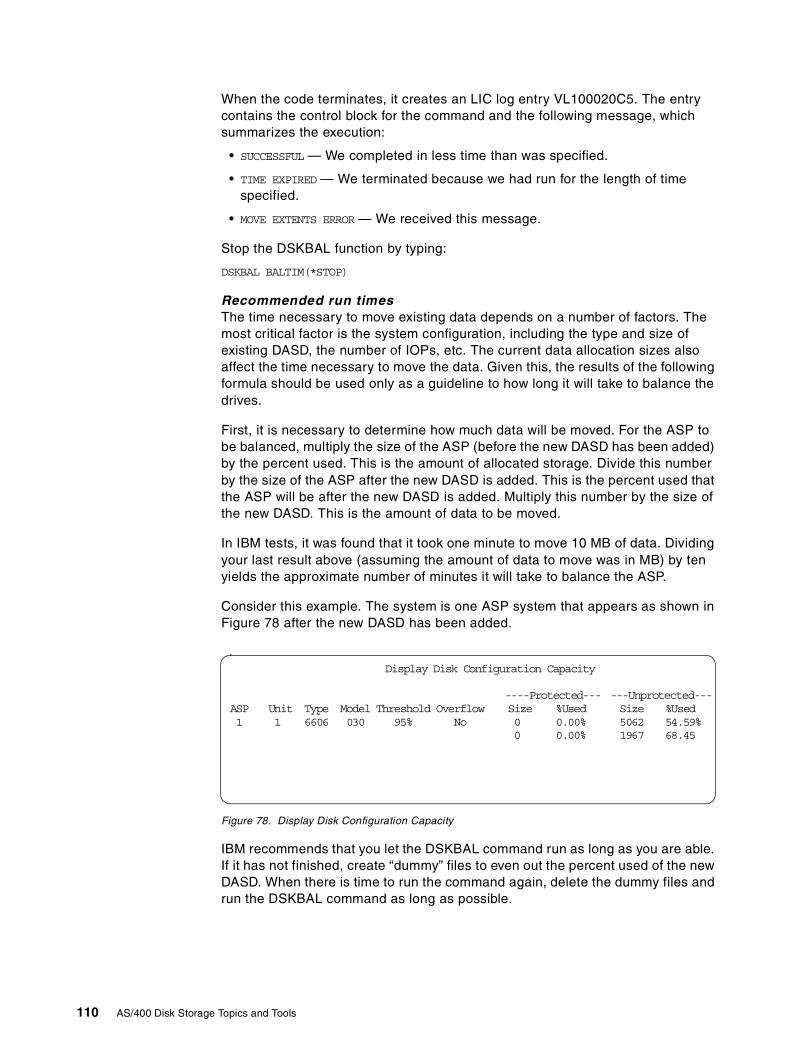
When the code terminates, it creates an LIC log entry VL100020C5. The entrycontains the control block for the command and the following message, whichsummarizes the execution:
• SUCCESSFUL — We completed in less time than was specified.
• TIME EXPIRED — We terminated because we had run for the length of timespecified.
• MOVE EXTENTS ERROR — We received this message.
Stop the DSKBAL function by typing:
DSKBAL BALTIM(*STOP)
Recommended run timesThe time necessary to move existing data depends on a number of factors. Themost critical factor is the system configuration, including the type and size ofexisting DASD, the number of IOPs, etc. The current data allocation sizes alsoaffect the time necessary to move the data. Given this, the results of the followingformula should be used only as a guideline to how long it will take to balance thedrives.
First, it is necessary to determine how much data will be moved. For the ASP tobe balanced, multiply the size of the ASP (before the new DASD has been added)by the percent used. This is the amount of allocated storage. Divide this numberby the size of the ASP after the new DASD is added. This is the percent used thatthe ASP will be after the new DASD is added. Multiply this number by the size ofthe new DASD. This is the amount of data to be moved.
In IBM tests, it was found that it took one minute to move 10 MB of data. Dividingyour last result above (assuming the amount of data to move was in MB) by tenyields the approximate number of minutes it will take to balance the ASP.
Consider this example. The system is one ASP system that appears as shown inFigure 78 after the new DASD has been added.
Figure 78. Display Disk Configuration Capacity
IBM recommends that you let the DSKBAL command run as long as you are able.If it has not finished, create “dummy” files to even out the percent used of the newDASD. When there is time to run the command again, delete the dummy files andrun the DSKBAL command as long as possible.
Display Disk Configuration Capacity
----Protected--- ---Unprotected---ASP Unit Type Model Threshold Overflow Size %Used Size %Used1 1 6606 030 95% No 0 0.00% 5062 54.59%
0 0.00% 1967 68.45
110 AS/400 Disk Storage Topics and Tools
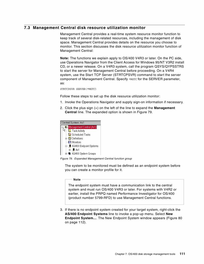
7.3 Management Central disk resource utilization monitor
Management Central provides a real-time system resource monitor function tokeep track of several disk-related resources, including the management of diskspace. Management Central provides details on the resource you choose tomonitor. This section discusses the disk resource utilization monitor function ofManagement Central:
Note: The functions we explain apply to OS/400 V4R3 or later. On the PC side,use Operations Navigator from the Client Access for Windows 95/NT V3R2 installCD, or a newer release. On a V4R3 system, call the program QSYS/QYPSSTRSto start the server for Management Central before proceeding. On a V4R4system, use the Start TCP Server (STRTCPSVR) command to start the servercomponent of Management Central. Specify *MGTC for the SERVER parameter,as:
STRTCPSVR SERVER(*MGTC)
Follow these steps to set up the disk resource utilization monitor:
1. Invoke the Operations Navigator and supply sign-on information if necessary.
2. Click the plus sign (+) on the left of the line to expand the ManagementCentral line. The expanded option is shown in Figure 79.
Figure 79. Expanded Management Central function group
The system to be monitored must be defined as an endpoint system beforeyou can create a monitor profile for it.
3. If there is no endpoint system created for your target system, right-click theAS/400 Endpoint Systems line to invoke a pop-up menu. Select NewEndpoint System.... The New Endpoint System window appears (Figure 80on page 112).
The endpoint system must have a communication link to the centralsystem and must run OS/400 V4R3 or later. For systems with V4R2 orearlier, install the PRPQ named Performance Investigator for OS/400(product number 5799-RFD) to use Management Central functions.
Note
Chapter 7. OS/400 disk storage management tools 111
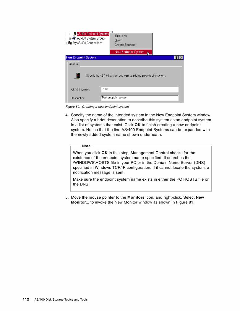
Figure 80. Creating a new endpoint system
4. Specify the name of the intended system in the New Endpoint System window.Also specify a brief description to describe this system as an endpoint systemin a list of systems that exist. Click OK to finish creating a new endpointsystem. Notice that the line AS/400 Endpoint Systems can be expanded withthe newly added system name shown underneath.
5. Move the mouse pointer to the Monitors icon, and right-click. Select NewMonitor... to invoke the New Monitor window as shown in Figure 81.
When you click OK in this step, Management Central checks for theexistence of the endpoint system name specified. It searches the\WINDOWS\HOSTS file in your PC or in the Domain Name Server (DNS)specified in Windows TCP/IP configuration. If it cannot locate the system, anotification message is sent.
Make sure the endpoint system name exists in either the PC HOSTS file orthe DNS.
Note
112 AS/400 Disk Storage Topics and Tools
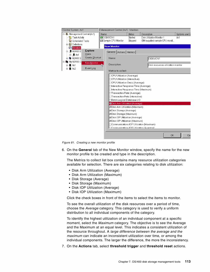
Figure 81. Creating a new monitor profile
6. On the General tab of the New Monitor window, specify the name for the newmonitor profile to be created and type in the description.
The Metrics to collect list box contains many resource utilization categoriesavailable for selection. There are six categories relating to disk utilization:
• Disk Arm Utilization (Average)• Disk Arm Utilization (Maximum)• Disk Storage (Average)• Disk Storage (Maximum)• Disk IOP Utilization (Average)• Disk IOP Utilization (Maximum)
Click the check boxes in front of the items to select the items to monitor.
To see the overall utilization of the disk resources over a period of time,choose the Average category. This category is used to verify a uniformdistribution to all individual components of the category.
To identify the highest utilization of an individual component at a specificmoment, select the Maximum category. The objective is to see the Averageand the Maximum at an equal level. This indicates a consistent utilization ofthe resource throughout. A large difference between the average and themaximum can indicate an inconsistent utilization over time, or among theindividual components. The larger the difference, the more the inconsistency.
7. On the Actions tab, select threshold trigger and threshold reset actions.
Chapter 7. OS/400 disk storage management tools 113
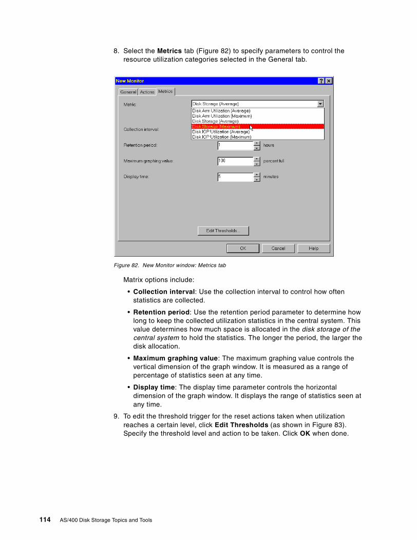
8. Select the Metrics tab (Figure 82) to specify parameters to control theresource utilization categories selected in the General tab.
Figure 82. New Monitor window: Metrics tab
Matrix options include:
• Collection interval: Use the collection interval to control how oftenstatistics are collected.
• Retention period: Use the retention period parameter to determine howlong to keep the collected utilization statistics in the central system. Thisvalue determines how much space is allocated in the disk storage of thecentral system to hold the statistics. The longer the period, the larger thedisk allocation.
• Maximum graphing value: The maximum graphing value controls thevertical dimension of the graph window. It is measured as a range ofpercentage of statistics seen at any time.
• Display time: The display time parameter controls the horizontaldimension of the graph window. It displays the range of statistics seen atany time.
9. To edit the threshold trigger for the reset actions taken when utilizationreaches a certain level, click Edit Thresholds (as shown in Figure 83).Specify the threshold level and action to be taken. Click OK when done.
114 AS/400 Disk Storage Topics and Tools
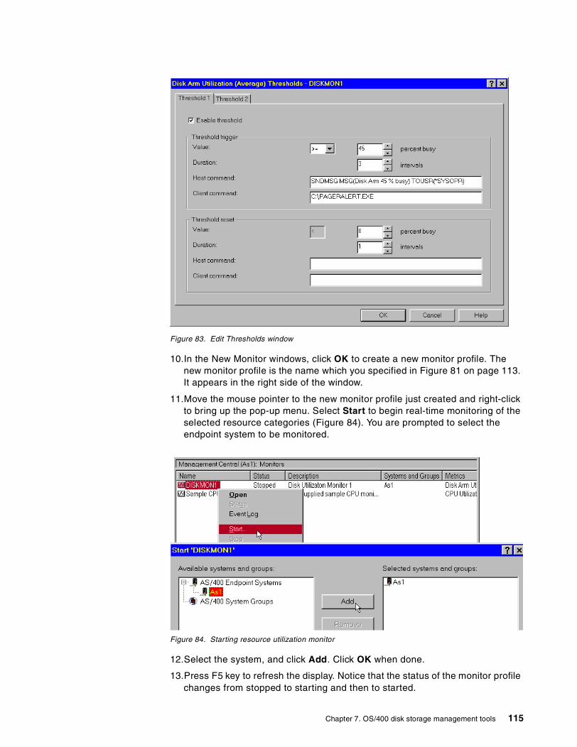
Figure 83. Edit Thresholds window
10.In the New Monitor windows, click OK to create a new monitor profile. Thenew monitor profile is the name which you specified in Figure 81 on page 113.It appears in the right side of the window.
11.Move the mouse pointer to the new monitor profile just created and right-clickto bring up the pop-up menu. Select Start to begin real-time monitoring of theselected resource categories (Figure 84). You are prompted to select theendpoint system to be monitored.
Figure 84. Starting resource utilization monitor
12.Select the system, and click Add. Click OK when done.
13.Press F5 key to refresh the display. Notice that the status of the monitor profilechanges from stopped to starting and then to started.
Chapter 7. OS/400 disk storage management tools 115
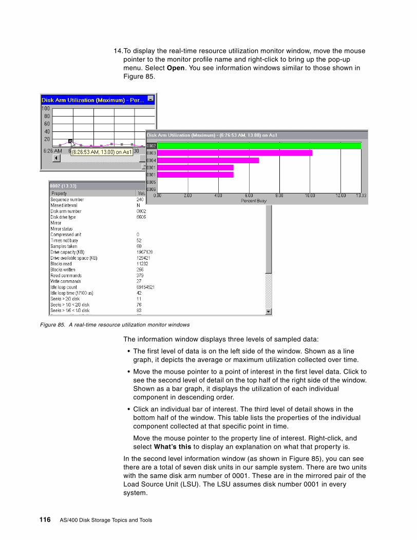
14.To display the real-time resource utilization monitor window, move the mousepointer to the monitor profile name and right-click to bring up the pop-upmenu. Select Open. You see information windows similar to those shown inFigure 85.
Figure 85. A real-time resource utilization monitor windows
The information window displays three levels of sampled data:
• The first level of data is on the left side of the window. Shown as a linegraph, it depicts the average or maximum utilization collected over time.
• Move the mouse pointer to a point of interest in the first level data. Click tosee the second level of detail on the top half of the right side of the window.Shown as a bar graph, it displays the utilization of each individualcomponent in descending order.
• Click an individual bar of interest. The third level of detail shows in thebottom half of the window. This table lists the properties of the individualcomponent collected at that specific point in time.
Move the mouse pointer to the property line of interest. Right-click, andselect What’s this to display an explanation on what that property is.
In the second level information window (as shown in Figure 85), you can seethere are a total of seven disk units in our sample system. There are two unitswith the same disk arm number of 0001. These are in the mirrored pair of theLoad Source Unit (LSU). The LSU assumes disk number 0001 in everysystem.
116 AS/400 Disk Storage Topics and Tools
At that particular point in time, unit number 0002 has the highest percent busyof about 13%. Unit numbers 0003, 0004, and 0001 appear in descendingorder of utilization. Disk units 0005 and 0006 appear to be idle.
The third level information is about disk number 0002 in particular because itis the most utilized unit at that moment (13.3%). In our example, it has read11,232 blocks, written 256 blocks, executed 379 read commands, 27 writecommands, and so on.
Use this third-level information to analyze performance-related information orthe availability-related status of each of the individual components. This helpsthe administrator identify if further action should be taken to rectify any issuesuncovered from this report.
15.Close the real-time monitor window. To display it again later, keep the monitorrunning.
Note: If you leave the monitor running continuously, be aware that the amountof AS/400 disk space used by the monitor depends on the length of time youspecify as retention period as shown in Figure 82 on page 114.
16.To end the monitor, right-click the monitor profile icon as shown in Figure 84on page 115, and select Stop.
Management Central is a user-friendly, graphical interface to help monitor diskresources utilization. Refer to Management Central: A Smart Way to ManageAS/400 Systems, SG24-5407, for detailed information on how to use manyfunctions delivered in Management Central.
7.4 Disk reorganization tool
To consolidate the unused space into one physical area, use the Start DiskReorganization (STRDSKRGZ) and End Disk Reorganization (ENDDSKRGZ) commands.They handle the task to rearrange unused blocks of disk space so that the emptychunks of disk space are consolidated into one physical contiguous area. It doesnot attempt to “defrag” objects in the used space of disk storage.
Refer to Figure 86 on page 118 for a conceptual view of the disk reorganizationfunction.
There is a tool shipped as a PTF that does the equivalent of the STRDSKRGZcommand. The difference is that the action occurs during the next IPL. Thecommand is called DEFRAG.
Note
Chapter 7. OS/400 disk storage management tools 117
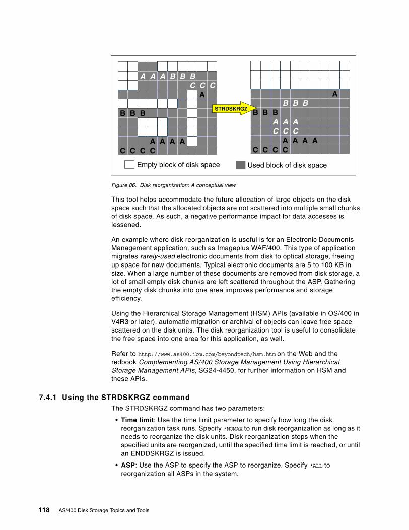
Figure 86. Disk reorganization: A conceptual view
This tool helps accommodate the future allocation of large objects on the diskspace such that the allocated objects are not scattered into multiple small chunksof disk space. As such, a negative performance impact for data accesses islessened.
An example where disk reorganization is useful is for an Electronic DocumentsManagement application, such as Imageplus WAF/400. This type of applicationmigrates rarely-used electronic documents from disk to optical storage, freeingup space for new documents. Typical electronic documents are 5 to 100 KB insize. When a large number of these documents are removed from disk storage, alot of small empty disk chunks are left scattered throughout the ASP. Gatheringthe empty disk chunks into one area improves performance and storageefficiency.
Using the Hierarchical Storage Management (HSM) APIs (available in OS/400 inV4R3 or later), automatic migration or archival of objects can leave free spacescattered on the disk units. The disk reorganization tool is useful to consolidatethe free space into one area for this application, as well.
Refer to http://www.as400.ibm.com/beyondtech/hsm.htm on the Web and theredbook Complementing AS/400 Storage Management Using HierarchicalStorage Management APIs, SG24-4450, for further information on HSM andthese APIs.
7.4.1 Using the STRDSKRGZ commandThe STRDSKRGZ command has two parameters:
• Time limit: Use the time limit parameter to specify how long the diskreorganization task runs. Specify *NOMAX to run disk reorganization as long as itneeds to reorganize the disk units. Disk reorganization stops when thespecified units are reorganized, until the specified time limit is reached, or untilan ENDDSKRGZ is issued.
• ASP: Use the ASP to specify the ASP to reorganize. Specify *ALL toreorganization all ASPs in the system.
A A A B B BC C C
A
B B B
A A A AC C C C
AB B B
B B BA A AC C C
A A A AC C C C
Empty block of disk space Used block of disk space
STRDSKRGZ
118 AS/400 Disk Storage Topics and Tools
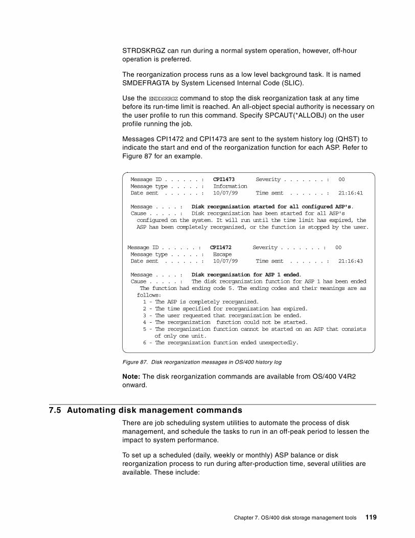
STRDSKRGZ can run during a normal system operation, however, off-houroperation is preferred.
The reorganization process runs as a low level background task. It is namedSMDEFRAGTA by System Licensed Internal Code (SLIC).
Use the ENDDSKRGZ command to stop the disk reorganization task at any timebefore its run-time limit is reached. An all-object special authority is necessary onthe user profile to run this command. Specify SPCAUT(*ALLOBJ) on the userprofile running the job.
Messages CPI1472 and CPI1473 are sent to the system history log (QHST) toindicate the start and end of the reorganization function for each ASP. Refer toFigure 87 for an example.
Figure 87. Disk reorganization messages in OS/400 history log
Note: The disk reorganization commands are available from OS/400 V4R2onward.
7.5 Automating disk management commands
There are job scheduling system utilities to automate the process of diskmanagement, and schedule the tasks to run in an off-peak period to lessen theimpact to system performance.
To set up a scheduled (daily, weekly or monthly) ASP balance or diskreorganization process to run during after-production time, several utilities areavailable. These include:
Message ID . . . . . . : CPI1473 Severity . . . . . . . : 00Message type . . . . . : InformationDate sent . . . . . . : 10/07/99 Time sent . . . . . . : 21:16:41
Message . . . . : Disk reorganization started for all configured ASP's.Cause . . . . . : Disk reorganization has been started for all ASP'sconfigured on the system. It will run until the time limit has expired, theASP has been completely reorganized, or the function is stopped by the user.
Message ID . . . . . . : CPI1472 Severity . . . . . . . : 00Message type . . . . . : EscapeDate sent . . . . . . : 10/07/99 Time sent . . . . . . : 21:16:43
Message . . . . : Disk reorganization for ASP 1 ended.Cause . . . . . : The disk reorganization function for ASP 1 has been ended
The function had ending code 5. The ending codes and their meanings are asfollows:1 - The ASP is completely reorganized.2 - The time specified for reorganization has expired.3 - The user requested that reorganization be ended.4 - The reorganization function could not be started.5 - The reorganization function cannot be started on an ASP that consists
of only one unit.6 - The reorganization function ended unexpectedly.
Chapter 7. OS/400 disk storage management tools 119
• The Work With Job Schedule Entries (WRKJOBSCDE) command. UseWRKJOBSCDE to set up daily, weekly, or monthly schedules for a singleAS/400 system.
• Management Central - Command Definition. Management Central is used toschedule running the same processes for multiple AS/400 endpoint systems atthe same time. To support this function, all endpoint systems must havecommunication links to the same central system. Daily, weekly, or monthlyschedules are supported.
• Use Job Scheduler for AS/400 (5769-JS1) Licensed Program Product formore complex scheduling (for example, to schedule an event that iscontingent upon the completion of another event).
Refer to AS/400 Work Management Guide, SC41-5306, for additional informationon WRKJOBSCDE.
Refer to the redbook Management Central - A Smart Way to Manage AS/400Systems, SG24-5407, for more information on Management Central.
Refer to AS/400 Job Scheduler, SC41-5300, for additional information on the JobScheduler licensed program.
7.6 Web sites on the Internet for system management
The following Web sites are good sources of updated information on AS/400system management.
• AS/400 Information Center: http://www.as400.ibm.com/infocenter• AS/400 Technical Studio: http://www.as400.ibm.com/techstudio• AS/400 Beyond Technology Page: http://www.as400.ibm.com/beyondtech
Bookmark these sites for easier access, using your Web browser.
120 AS/400 Disk Storage Topics and Tools
Chapter 8. Runaway DASD
As modern application software packages become more and more sophisticated,they demand more and more processor power and disk space to supportadvanced functionality. Recent studies show that a typical AS/400 customerincreases their DASD consumption by 30% per year. Therefore, a good DASDmanagement strategy forms an important part of the overall AS/400 systemmanagement plan to protect a growing company’s asset.
IBM recommends that you maintain DASD utilization at less than 70 to 75% foroptimal performance. However, from time to time many systems exceed thisguideline.
Examples of when this occurs are:
• A new version of the application software package consumes more disk spacethan the prior release.
• The business experiences an unexpected upturn in sales.
• Budget constraints prevent the installation of additional disk resource tohandle expected growth.
• There is improper planning or the lack of a good DASD maintenance ormanagement strategy.
Whatever the reason for the increase in DASD usage, whether it is businessrelated, planned, or unplanned, it is important that you are aware that this growthimpacts the performance of your system. This chapter outlines tools available toanalyze the cause for the growth.
8.1 Disk and growth terminology
We start with some commonly used terminology used to describe disk topics andthe management of disk growth.
• Controlled growth
The most common cause of DASD consumption problems is natural businessgrowth. An increase in business generates more transactions, which in turnrequire more disk space to store them. This is referred to as “controlledgrowth”.
• Uncontrolled growth
There are times when jobs consume more DASD than would usually beexpected. For example, an application software bug causes a program to adda lot more records to a database file than it should. This growth is referred toas “uncontrolled growth”.
The information described in this chapter is based on OS/400 Version 4Release 4 of OS/400 and is by no means exhaustive.
Note
© Copyright IBM Corp. 2000 121
• Runaway DASD
In extreme cases, “Uncontrolled Growth” consumes DASD at such a rate that,unless stopped, causes an application or system outage. This uncontrolledgrowth is referred to as “Runaway DASD”.
8.2 Storage concepts
To understand why an AS/400 system can run out of storage, it is necessary to befamiliar with some of the basic concepts of storage usage on the AS/400 systemrelative to data types and how they are stored:
• Data on the AS/400 system is stored either on hard disk (DASD) or in realmemory.
• The AS/400 system uses a storage management architecture called SingleLevel Storage (SLS). SLS treats all addressable memory (either hard diskstorage or real memory) as one addressable space. This allows greatflexibility for application programs and users, and also increases the effectiveaddress space on the system.
• To survive across an IPL, data needs to be on DASD.
• There are two types of data from the point of view of storage on the AS/400system: permanent and temporary.
– Permanent is data that survives across an IPL if it is on disk (for example,database files).
– Temporary is data that does not survive across an IPL. An example is thework space for a job that is terminated by an IPL. Temporary objects arenot expected to be re-used.
• DASD on the AS/400 system can be divided into groups called AuxiliaryStorage Pools (ASPs). There is always one ASP, known as the system ASP.There can be up to 16 defined ASPs: 15 known as user ASPs and the onesystem ASP.
• A user ASP has a finite amount of storage available to it, defined by theamount of DASD configured in it. When the amount of data in the ASPreaches 100% of the capacity available, new data directed to that ASP isre-directed to the system ASP instead. This data is called Overflow data.
• The % system ASP used field in the top right corner of the WRKSYSSTSscreen (Figure 88) reflects the total of Permanent and Temporary storageused in the system ASP. If this value reaches 100%, the system stops, as thesystem ASP has nowhere to overflow.
122 AS/400 Disk Storage Topics and Tools
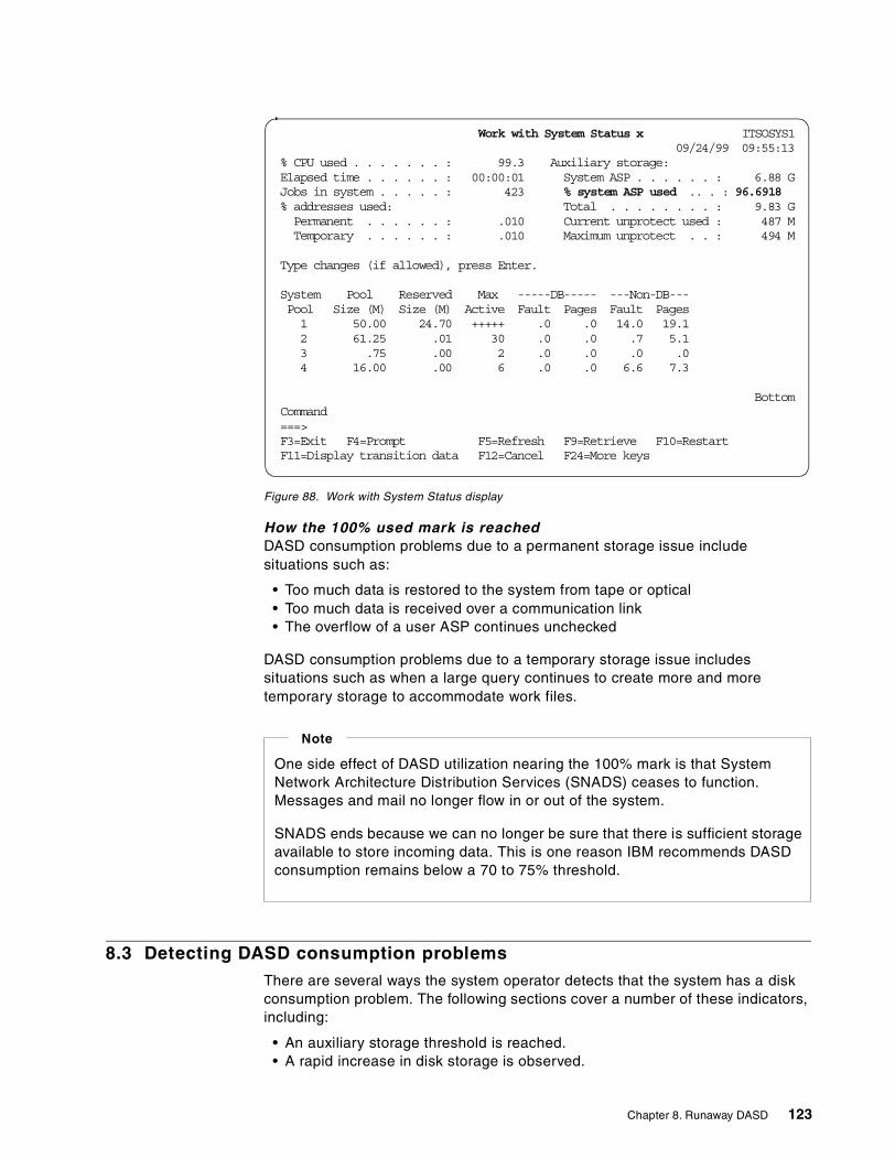
Figure 88. Work with System Status display
How the 100% used mark is reachedDASD consumption problems due to a permanent storage issue includesituations such as:
• Too much data is restored to the system from tape or optical• Too much data is received over a communication link• The overflow of a user ASP continues unchecked
DASD consumption problems due to a temporary storage issue includessituations such as when a large query continues to create more and moretemporary storage to accommodate work files.
8.3 Detecting DASD consumption problems
There are several ways the system operator detects that the system has a diskconsumption problem. The following sections cover a number of these indicators,including:
• An auxiliary storage threshold is reached.• A rapid increase in disk storage is observed.
Work with System Status xxxxxxxxxxx xxITSOSYS109/24/99 09:55:13
% CPU used . . . . . . . : 99.3 Auxiliary storage:Elapsed time . . . . . . : 00:00:01 System ASP . . . . . . : 6.88 GJobs in system . . . . . : 423 % system ASP used .. . : 96.6918% addresses used: Total . . . . . . . . : 9.83 GPermanent . . . . . . : .010 Current unprotect used : 487 MTemporary . . . . . . : .010 Maximum unprotect . . : 494 M
Type changes (if allowed), press Enter.
System Pool Reserved Max -----DB----- ---Non-DB---Pool Size (M) Size (M) Active Fault Pages Fault Pages1 50.00 24.70 +++++ .0 .0 14.0 19.12 61.25 .01 30 .0 .0 .7 5.13 .75 .00 2 .0 .0 .0 .04 16.00 .00 6 .0 .0 6.6 7.3
BottomCommand===>F3=Exit F4=Prompt F5=Refresh F9=Retrieve F10=RestartF11=Display transition data F12=Cancel F24=More keys
One side effect of DASD utilization nearing the 100% mark is that SystemNetwork Architecture Distribution Services (SNADS) ceases to function.Messages and mail no longer flow in or out of the system.
SNADS ends because we can no longer be sure that there is sufficient storageavailable to store incoming data. This is one reason IBM recommends DASDconsumption remains below a 70 to 75% threshold.
Note
Chapter 8. Runaway DASD 123
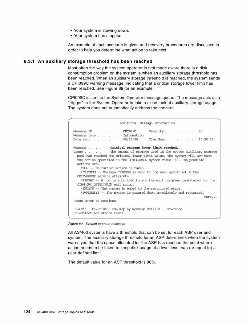
• Your system is slowing down.• Your system has stopped
An example of each scenario is given and recovery procedures are discussed inorder to help you determine what action to take next.
8.3.1 An auxiliary storage threshold has been reachedMost often the way the system operator is first made aware there is a diskconsumption problem on the system is when an auxiliary storage threshold hasbeen reached. When an auxiliary storage threshold is reached, the system sendsa CPI099C warning message, indicating that a critical storage lower limit hasbeen reached. See Figure 89 for an example.
CPI099C is sent to the System Operator message queue. The message acts as a“trigger” to the System Operator to take a close look at auxiliary storage usage.The system does not automatically address the concern.
Figure 89. System operator message
All AS/400 systems have a threshold that can be set for each ASP user andsystem. The auxiliary storage threshold for an ASP determines when the systemwarns you that the space allocated for the ASP has reached the point whereaction needs to be taken to keep disk usage at a level less than (or equal to) auser-defined limit.
The default value for an ASP threshold is 90%.
Additional Message Information
Message ID . . . . . . : CPI099C Severity . . . . . . . : 90Message type . . . . . : InformationDate sent . . . . . . : 09/17/99 Time Sent . . . . . . : 10:20:15
Message . . . . : Critical storage lower limit reached.Cause . . . . . : The amount of storage used in the system auxiliary storagepool has reached the critical lower limit value. The system will now takethe action specified in the QSTGLOWACN system value: &5. The possibleactions are:*MSG -- No further action is taken.*CRITMSG -- Message CPI099B is sent to the user specified by the
CRITMSGUSR service attribute.*REGFAC -- A job is submitted to run the exit programs registered for the
QIBM_QWC_QSTGLOWACN exit point.*ENDSYS -- The system is ended to the restricted state.*PWRDWNSYS -- The system is powered down immediately and restarted.
More...Press Enter to continue.
F3=Exit F6=Print F9=Display message details F12=CancelF21=Select Assistance Level
124 AS/400 Disk Storage Topics and Tools
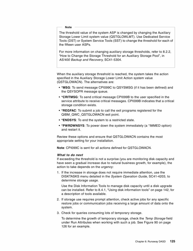
When the auxiliary storage threshold is reached, the system takes the actionspecified in the Auxiliary Storage Lower Limit Action system value(QSTGLOWACN). The alternatives are:
• *MSG: To send message CPI099C to QSYSMSG (if it has been defined) andthe QSYSOPR message queue.
• *CRITMSG: To send critical message CPI099B to the user specified in theservice attribute to receive critical messages. CPI099B indicates that a criticalstorage condition exists.
• *REGFAC: To submit a job to call the exit programs registered for theQIBM_QWC_QSTGLOWACN exit point.
• *ENDSYS: To end the system to a restricted state.
• *PWRDWNSYS: To power down the system immediately (a *IMMED option)and restart it.
Review these options and ensure that QSTGLOWACN contains the mostappropriate setting for your installation.
Note: CPI099C is sent for all actions defined for QSTGLOWACN.
What to do nextIf exceeding the threshold is not a surprise (you are monitoring disk capacity andhave seen a gradual increase due to natural business growth, for example), theaction to take depends on the urgency:
1. If the increase in storage does not require immediate attention, use theDISKTASKS menu detailed in the System Operation Guide, SC41-4203, todetermine storage usage.
Use the Disk Information Tools to manage disk capacity until a disk upgradecan be installed. Refer to 8.4.1, “Using disk information tools” on page 142, fora description of tools available.
2. If storage use requires prompt attention, check active jobs for any specificrestore jobs or communication jobs receiving a large amount of data onto thesystem.
3. Check for queries consuming lots of temporary storage.
To determine the growth of temporary storage, check the Temp Storage fieldunder Run Attributes when working with such a job. See Figure 90 on page126 for an example.
The threshold value of the system ASP is changed by changing the AuxiliaryStorage Lower Limit system value (QSTGLOWLMT). Use Dedicated ServiceTools (DST) or System Service Tools (SST) to change the threshold for each ofthe fifteen user ASPs.
For more information on changing auxiliary storage thresholds, refer to 8.2.2,“How to Change the Storage Threshold for an Auxiliary Storage Pool”, inAS/400 Backup and Recovery, SC41-5304.
Note
Chapter 8. Runaway DASD 125
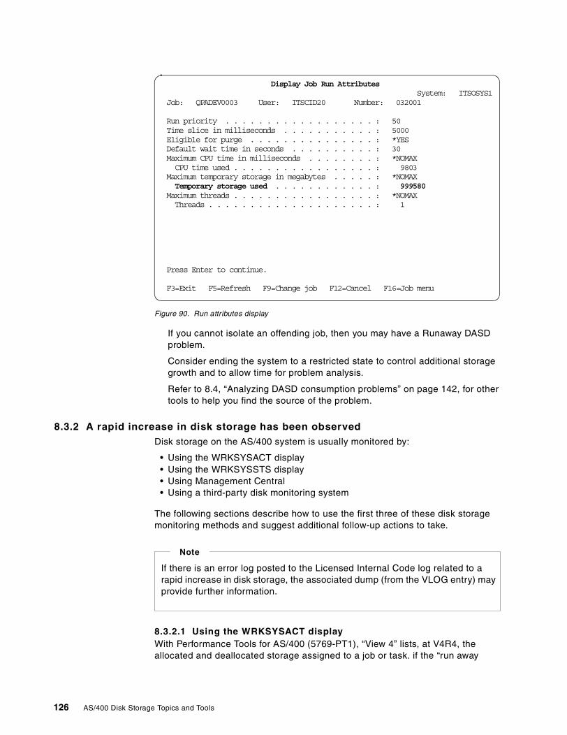
Figure 90. Run attributes display
If you cannot isolate an offending job, then you may have a Runaway DASDproblem.
Consider ending the system to a restricted state to control additional storagegrowth and to allow time for problem analysis.
Refer to 8.4, “Analyzing DASD consumption problems” on page 142, for othertools to help you find the source of the problem.
8.3.2 A rapid increase in disk storage has been observedDisk storage on the AS/400 system is usually monitored by:
• Using the WRKSYSACT display• Using the WRKSYSSTS display• Using Management Central• Using a third-party disk monitoring system
The following sections describe how to use the first three of these disk storagemonitoring methods and suggest additional follow-up actions to take.
8.3.2.1 Using the WRKSYSACT displayWith Performance Tools for AS/400 (5769-PT1), “View 4” lists, at V4R4, theallocated and deallocated storage assigned to a job or task. if the “run away
Display Job Run AttributesSystem: ITSOSYS1
Job: QPADEV0003 User: ITSCID20xxxxxx Number: 032001
Run priority . . . . . . . . . . . . . . . . . . : 50Time slice in milliseconds . . . . . . . . . . . : 5000Eligible for purge . . . . . . . . . . . . . . . : *YESDefault wait time in seconds . . . . . . . . . . : 30Maximum CPU time in milliseconds . . . . . . . . : *NOMAXCPU time used . . . . . . . . . . . . . . . . . : 9803
Maximum temporary storage in megabytes . . . . . : *NOMAXTemporary storage used . . . . . . . . . . . . : 999580
Maximum threads . . . . . . . . . . . . . . . . . : *NOMAXThreads . . . . . . . . . . . . . . . . . . . . : 1
Press Enter to continue.
F3=Exit F5=Refresh F9=Change job F12=Cancel F16=Job menu
If there is an error log posted to the Licensed Internal Code log related to arapid increase in disk storage, the associated dump (from the VLOG entry) mayprovide further information.
Note
126 AS/400 Disk Storage Topics and Tools
DASD” job is a long running job, you can identify it from the WRKSYSACTdisplay. For an example, see Figure 95 on page 131.
8.3.2.2 Using the WRKSYSSTS displayThe Work with System Status display (as shown in Figure 91) shows a set ofstatistics depicting the current status of the system. One field displayed is thepercentage of the system auxiliary storage pool (ASP) currently in use.
The statistical information is gathered during an identified time interval (shown asthe elapsed time). The data can be updated by extending the measurement timeinterval (use F5), or it can be reset and a new time interval started to gather anew set of data (use F10).
Figure 91. Work with System Status display
8.3.2.3 Using Management CentralManagement Central is a suite of graphical systems management functions.Management Central is an optionally-installable component of OperationsNavigator, the strategic graphical user interface for IBM AS/400 systems. Thesefunctions are available with OS/400 Version 4 Release 3 (V4R3) and laterreleases.
Work with System Status xxxxxxxxxxxxxxITSOSYS109/24/99 09:55:13
% CPU used . . . . . . . : 99.3 Auxiliary storage:Elapsed time . . . . . . : 00:00:01 System ASP . . . . . . : 6.88 GJobs in system . . . . . : 423 % system ASP used . . : _96.6918% addresses used: Total . . . . . . . . : 9.83 GPermanent . . . . . . : .010 Current unprotect used : 487 MTemporary . . . . . . : .010 Maximum unprotect . . : 494 M
Type changes (if allowed), press Enter.
System Pool Reserved Max -----DB----- ---Non-DB---Pool Size (M) Size (M) Active Fault Pages Fault Pages1 50.00 24.70 +++++ .0 .0 14.0 19.12 61.25 .01 30 .0 .0 .7 5.13 .75 .00 2 .0 .0 .0 .04 16.00 .00 6 .0 .0 6.6 7.3
BottomCommand===>F3=Exit F4=Prompt F5=Refresh F9=Retrieve F10=RestartF11=Display transition data F12=Cancel F24=More keysCritical storage condition reached.
Chapter 8. Runaway DASD 127
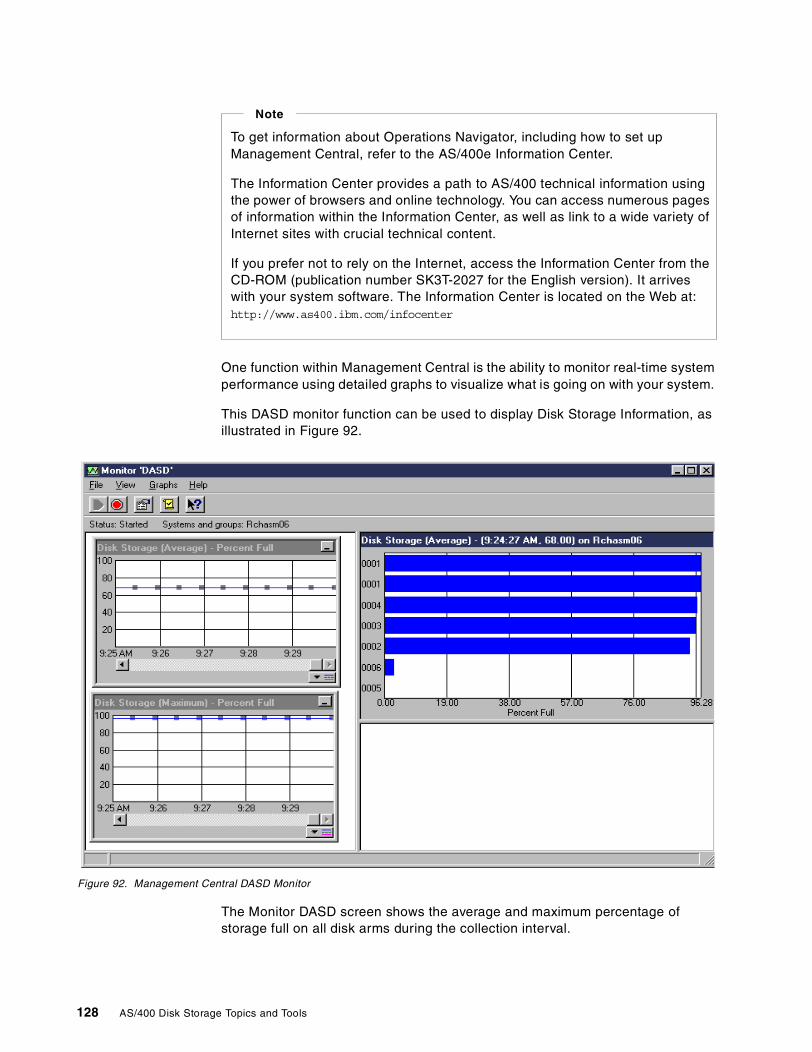
One function within Management Central is the ability to monitor real-time systemperformance using detailed graphs to visualize what is going on with your system.
This DASD monitor function can be used to display Disk Storage Information, asillustrated in Figure 92.
Figure 92. Management Central DASD Monitor
The Monitor DASD screen shows the average and maximum percentage ofstorage full on all disk arms during the collection interval.
To get information about Operations Navigator, including how to set upManagement Central, refer to the AS/400e Information Center.
The Information Center provides a path to AS/400 technical information usingthe power of browsers and online technology. You can access numerous pagesof information within the Information Center, as well as link to a wide variety ofInternet sites with crucial technical content.
If you prefer not to rely on the Internet, access the Information Center from theCD-ROM (publication number SK3T-2027 for the English version). It arriveswith your system software. The Information Center is located on the Web at:http://www.as400.ibm.com/infocenter
Note
128 AS/400 Disk Storage Topics and Tools
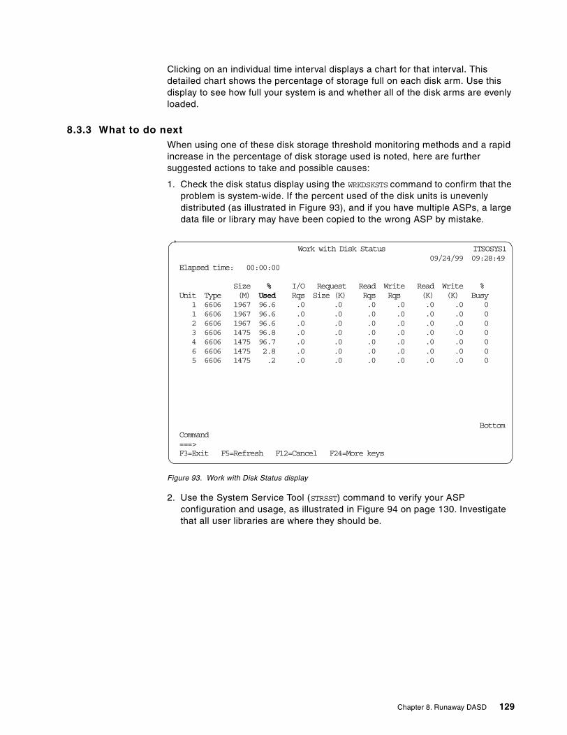
Clicking on an individual time interval displays a chart for that interval. Thisdetailed chart shows the percentage of storage full on each disk arm. Use thisdisplay to see how full your system is and whether all of the disk arms are evenlyloaded.
8.3.3 What to do nextWhen using one of these disk storage threshold monitoring methods and a rapidincrease in the percentage of disk storage used is noted, here are furthersuggested actions to take and possible causes:
1. Check the disk status display using the WRKDSKSTS command to confirm that theproblem is system-wide. If the percent used of the disk units is unevenlydistributed (as illustrated in Figure 93), and if you have multiple ASPs, a largedata file or library may have been copied to the wrong ASP by mistake.
Figure 93. Work with Disk Status display
2. Use the System Service Tool (STRSST) command to verify your ASPconfiguration and usage, as illustrated in Figure 94 on page 130. Investigatethat all user libraries are where they should be.
Work with Disk Status xxxxxxxxxxxxxxxxxxxxITSOSYS109/24/99 09:28:49
Elapsed time: 00:00:00
Size % I/O Request Read Write Read Write %Unit Type (M) Used Rqs Size (K) Rqs Rqs (K) (K) Busy
1 6606 1967 96.6 .0 .0 .0 .0 .0 .0 01 6606 1967 96.6 .0 .0 .0 .0 .0 .0 02 6606 1967 96.6 .0 .0 .0 .0 .0 .0 03 6606 1475 96.8 .0 .0 .0 .0 .0 .0 04 6606 1475 96.7 .0 .0 .0 .0 .0 .0 06 6606 1475 2.8 .0 .0 .0 .0 .0 .0 05 6606 1475 .2 .0 .0 .0 .0 .0 .0 0
BottomCommand===>F3=Exit F5=Refresh F12=Cancel F24=More keys
Chapter 8. Runaway DASD 129
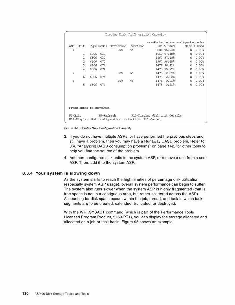
Figure 94. Display Disk Configuration Capacity
3. If you do not have multiple ASPs, or have performed the previous steps andstill have a problem, then you may have a Runaway DASD problem. Refer to8.4, “Analyzing DASD consumption problems” on page 142, for other tools tohelp you find the source of the problem.
4. Add non-configured disk units to the system ASP, or remove a unit from a userASP. Then, add it to the system ASP.
8.3.4 Your system is slowing downAs the system starts to reach the high nineties of percentage disk utilization(especially system ASP usage), overall system performance can begin to suffer.The system also runs slower when the system ASP is highly fragmented (that is,free space is not in a contiguous area, but rather scattered across the ASP).Accounting for disk space occurs within the job, thread, and task in which tasksegments are to be created, extended, truncated, or destroyed.
With the WRKSYSACT command (which is part of the Performance ToolsLicensed Program Product, 5769-PT1), you can display the storage allocated andallocated on a job or task basis. Figure 95 shows an example.
Display Disk Configuration Capacity
----Protected--- ---Unprotected--ASP Unit Type Model Threshold Overflow Size % Used Size % Used1 90% No 6884 96.94% 0 0.00%
1 6606 030 1967 97.48% 0 0.00%1 6606 030 1967 97.48% 0 0.00%2 6606 070 1967 96.65% 0 0.00%3 6606 074 1475 96.81% 0 0.00%4 6606 074 1475 96.72% 0 0.00%
2 90% No 1475 2.82% 0 0.00%6 6606 074 1475 2.82% 0 0.00%
3 90% No 1475 0.21% 0 0.00%5 6606 074 1475 0.21% 0 0.00%
Press Enter to continue.
F3=Exit F5=Refresh F10=Display disk unit detailsF11=Display disk configuration protection F12=Cancel
130 AS/400 Disk Storage Topics and Tools
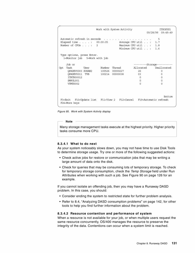
Figure 95. Work with System Activity display
8.3.4.1 What to do nextAs your system noticeably slows down, you may not have time to use Disk Toolsto determine storage usage. Try one or more of the following suggested actions:
• Check active jobs for restore or communication jobs that may be writing alarge amount of data onto the disk.
• Check for queries that may be consuming lots of temporary storage. To checkfor temporary storage consumption, check the Temp Storage field under RunAttributes when working with such a job. See Figure 90 on page 126 for anexample.
If you cannot isolate an offending job, then you may have a Runaway DASDproblem. In this case, you should:
• Consider ending the system to restricted state for further problem analysis.
• Refer to 8.4, “Analyzing DASD consumption problems” on page 142, for othertools to help you find further information about the problem.
8.3.4.2 Resource contention and performance of systemWhen a resource is not available for your job, or when multiple users request thesame resource concurrently, OS/400 manages the resource to preserve theintegrity of the data. Contentions can occur when a system limit is reached.
Work with System Activity ITSOSYS109/28/99 09:49:49
Automatic refresh in seconds . . . . . . . . . . . . . . . . . 5Elapsed time . . . . : 00:00:05 Average CPU util . . : 1.7Number of CPUs . . . : 2 Maximum CPU util . . : 1.8
Minimum CPU util . . : 1.6
Type options, press Enter.1=Monitor job 5=Work with job
Job or ---------Storage-----------Opt Task User Number Thread Allocated Deallocated
QPADEV0003 SUSAN2 100526 00000227 26 0QPADEV0011 TVB 100214 00000038 03 0ITRTR00012 0 0SMPOL001 0 0VTMTS002 0 0
BottomF3=Exit F10=Update list F11=View 2 F12=Cancel F19=Automatic refreshF24=More keys
Many storage management tasks execute at the highest priority. Higher prioritytasks consume more CPU.
Note
Chapter 8. Runaway DASD 131
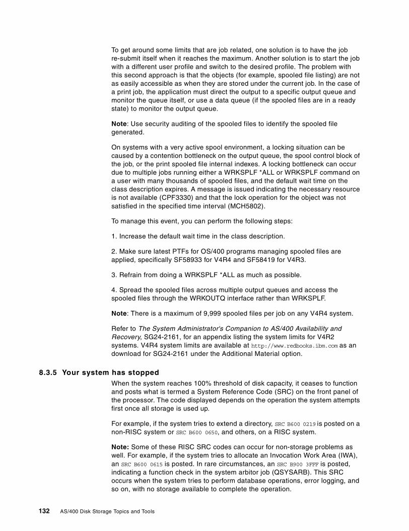
To get around some limits that are job related, one solution is to have the jobre-submit itself when it reaches the maximum. Another solution is to start the jobwith a different user profile and switch to the desired profile. The problem withthis second approach is that the objects (for example, spooled file listing) are notas easily accessible as when they are stored under the current job. In the case ofa print job, the application must direct the output to a specific output queue andmonitor the queue itself, or use a data queue (if the spooled files are in a readystate) to monitor the output queue.
Note: Use security auditing of the spooled files to identify the spooled filegenerated.
On systems with a very active spool environment, a locking situation can becaused by a contention bottleneck on the output queue, the spool control block ofthe job, or the print spooled file internal indexes. A locking bottleneck can occurdue to multiple jobs running either a WRKSPLF *ALL or WRKSPLF command ona user with many thousands of spooled files, and the default wait time on theclass description expires. A message is issued indicating the necessary resourceis not available (CPF3330) and that the lock operation for the object was notsatisfied in the specified time interval (MCH5802).
To manage this event, you can perform the following steps:
1. Increase the default wait time in the class description.
2. Make sure latest PTFs for OS/400 programs managing spooled files areapplied, specifically SF58933 for V4R4 and SF58419 for V4R3.
3. Refrain from doing a WRKSPLF *ALL as much as possible.
4. Spread the spooled files across multiple output queues and access thespooled files through the WRKOUTQ interface rather than WRKSPLF.
Note: There is a maximum of 9,999 spooled files per job on any V4R4 system.
Refer to The System Administrator's Companion to AS/400 Availability andRecovery, SG24-2161, for an appendix listing the system limits for V4R2systems. V4R4 system limits are available at http://www.redbooks.ibm.com as andownload for SG24-2161 under the Additional Material option.
8.3.5 Your system has stoppedWhen the system reaches 100% threshold of disk capacity, it ceases to functionand posts what is termed a System Reference Code (SRC) on the front panel ofthe processor. The code displayed depends on the operation the system attemptsfirst once all storage is used up.
For example, if the system tries to extend a directory, SRC B600 0219 is posted on anon-RISC system or SRC B600 0650, and others, on a RISC system.
Note: Some of these RISC SRC codes can occur for non-storage problems aswell. For example, if the system tries to allocate an Invocation Work Area (IWA),an SRC B600 0615 is posted. In rare circumstances, an SRC B900 3FFF is posted,indicating a function check in the system arbitor job (QSYSARB). This SRCoccurs when the system tries to perform database operations, error logging, andso on, with no storage available to complete the operation.
132 AS/400 Disk Storage Topics and Tools
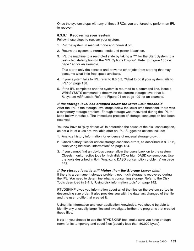
Once the system stops with any of these SRCs, you are forced to perform an IPLto recover.
8.3.5.1 Recovering your systemFollow these steps to recover your system:
1. Put the system in manual mode and power it off.
2. Return the system to normal mode and power it back on.
3. IPL the machine to a restricted state by taking a “Y” for the Start System to arestricted state option on the “IPL Options Display”. Refer to Figure 105 onpage 140 for an example.
This starts only the console and prevents other jobs from starting that mayconsume what little free space available.
4. If your system fails to IPL, refer to 8.3.5.3, “What to do if your system fails toIPL” on page 138.
5. If the IPL completes and the system is returned to a command line, issue aWRKSYSSTS command to determine the current storage level (that is,% system ASP used). Refer to Figure 91 on page 127 for an example.
If the storage level has dropped below the lower limit thresholdAfter the IPL, if the storage level drops below the lower limit threshold, there wasa temporary storage problem. Enough storage was recovered during the IPL tokeep below threshold. The immediate problem of storage consumption has beenresolved.
You now have to “play detective” to determine the cause of the disk consumption,as not a lot of clues are available after an IPL. Suggested actions include:
1. Analyze history information for evidence of unusual storage growth.
2. Check history files for critical storage condition errors, as described in 8.3.5.2,“Analyzing historical information” on page 134.
3. If you cannot find an obvious cause, allow the users back on to the system.Closely monitor active jobs for high disk I/O or high DASD consumption. Usethe tools described in 8.4, “Analyzing DASD consumption problems” on page142.
If the storage level is still higher than the Storage Lower LimitIf there is a permanent storage problem, not much storage is recovered duringthe IPL. You need to determine what is consuming storage. Refer to the DiskTools described in 8.4.1, “Using disk information tools” on page 142.
RTVDSKINF gives you information about all of the files on the system sorted indescending size order. It also provides you with the date last changed of the fileand the user profile that created it.
Using this information and your application knowledge, you should be able toidentify any unusually large files and investigate further the programs that createdthese files.
Note: If you choose to use the RTVDSKINF tool, make sure you have enoughroom for its temporary and spool files (usually less than 50,000 bytes).
Chapter 8. Runaway DASD 133
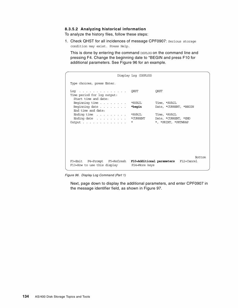
8.3.5.2 Analyzing historical informationTo analyze the history files, follow these steps:
1. Check QHST for all incidences of message CPF0907: Serious storage
condition may exist. Press Help.
This is done by entering the command DSPLOG on the command line andpressing F4. Change the beginning date to *BEGIN and press F10 foradditional parameters. See Figure 96 for an example.
Figure 96. Display Log Command (Part 1)
Next, page down to display the additional parameters, and enter CPF0907 inthe message identifier field, as shown in Figure 97.
Display Log (DSPLOG)
Type choices, press Enter.
Log . . . . . . . . . . . . . . QHST QHSTTime period for log output:Start time and date:Beginning time . . . . . . . . *AVAIL Time, *AVAILBeginning date . . . . . . . . *begin Date, *CURRENT, *BEGINEnd time and date:Ending time . . . . . . . . . *AVAIL Time, *AVAILEnding date . . . . . . . . . *CURRENT Date, *CURRENT, *END
Output . . . . . . . . . . . . . * *, *PRINT, *PRTWRAP
BottomF3=Exit F4=Prompt F5=Refresh F10=Additional parameters F12=CancelF13=How to use this display F24=More keys
134 AS/400 Disk Storage Topics and Tools
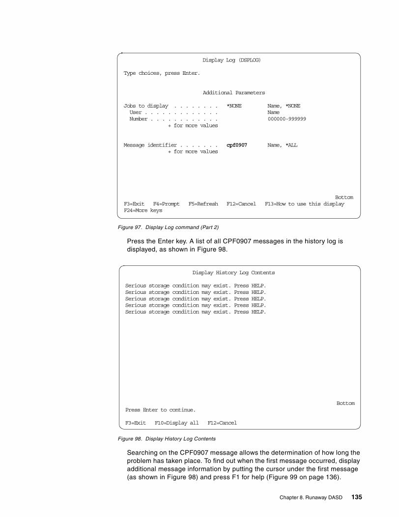
Figure 97. Display Log command (Part 2)
Press the Enter key. A list of all CPF0907 messages in the history log isdisplayed, as shown in Figure 98.
Figure 98. Display History Log Contents
Searching on the CPF0907 message allows the determination of how long theproblem has taken place. To find out when the first message occurred, displayadditional message information by putting the cursor under the first message(as shown in Figure 98) and press F1 for help (Figure 99 on page 136).
Display Log (DSPLOG)
Type choices, press Enter.
Additional Parameters
Jobs to display . . . . . . . . *NONE Name, *NONEUser . . . . . . . . . . . . . NameNumber . . . . . . . . . . . . 000000-999999
+ for more values
Message identifier . . . . . . . cpf0907 Name, *ALL+ for more values
BottomF3=Exit F4=Prompt F5=Refresh F12=Cancel F13=How to use this displayF24=More keys
Display History Log Contents
Serious storage condition may exist. Press HELP.Serious storage condition may exist. Press HELP.Serious storage condition may exist. Press HELP.Serious storage condition may exist. Press HELP.Serious storage condition may exist. Press HELP.
BottomPress Enter to continue.
F3=Exit F10=Display all F12=Cancel
Chapter 8. Runaway DASD 135
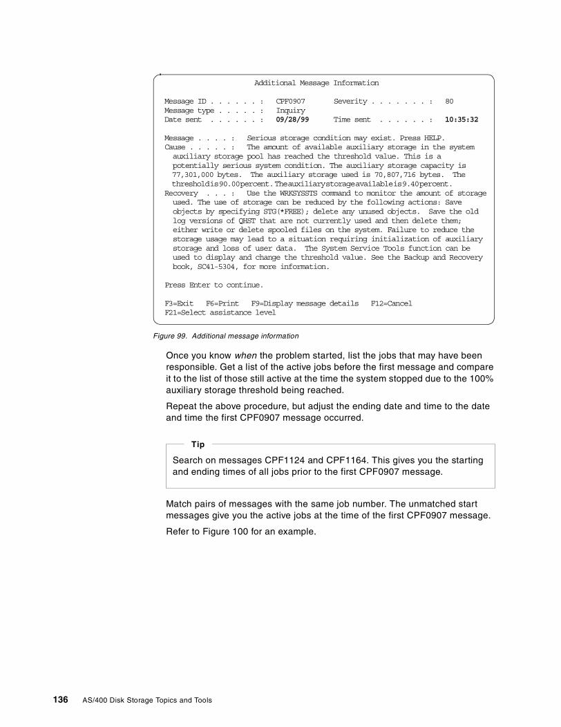
Figure 99. Additional message information
Once you know when the problem started, list the jobs that may have beenresponsible. Get a list of the active jobs before the first message and compareit to the list of those still active at the time the system stopped due to the 100%auxiliary storage threshold being reached.
Repeat the above procedure, but adjust the ending date and time to the dateand time the first CPF0907 message occurred.
Match pairs of messages with the same job number. The unmatched startmessages give you the active jobs at the time of the first CPF0907 message.
Refer to Figure 100 for an example.
Additional Message Information
Message ID . . . . . . : CPF0907 Severity . . . . . . . : 80Message type . . . . . : InquiryDate sent . . . . . . : 09/28/99 Time sent . . . . . . : 10:35:32
Message . . . . : Serious storage condition may exist. Press HELP.Cause . . . . . : The amount of available auxiliary storage in the systemauxiliary storage pool has reached the threshold value. This is apotentially serious system condition. The auxiliary storage capacity is77,301,000 bytes. The auxiliary storage used is 70,807,716 bytes. Thethresholdis90.00percent.Theauxiliarystorageavailableis9.40percent.
Recovery . . . : Use the WRKSYSSTS command to monitor the amount of storageused. The use of storage can be reduced by the following actions: Saveobjects by specifying STG(*FREE); delete any unused objects. Save the oldlog versions of QHST that are not currently used and then delete them;either write or delete spooled files on the system. Failure to reduce thestorage usage may lead to a situation requiring initialization of auxiliarystorage and loss of user data. The System Service Tools function can beused to display and change the threshold value. See the Backup and Recoverybook, SC41-5304, for more information.
Press Enter to continue.
F3=Exit F6=Print F9=Display message details F12=CancelF21=Select assistance level
Search on messages CPF1124 and CPF1164. This gives you the startingand ending times of all jobs prior to the first CPF0907 message.
Tip
136 AS/400 Disk Storage Topics and Tools
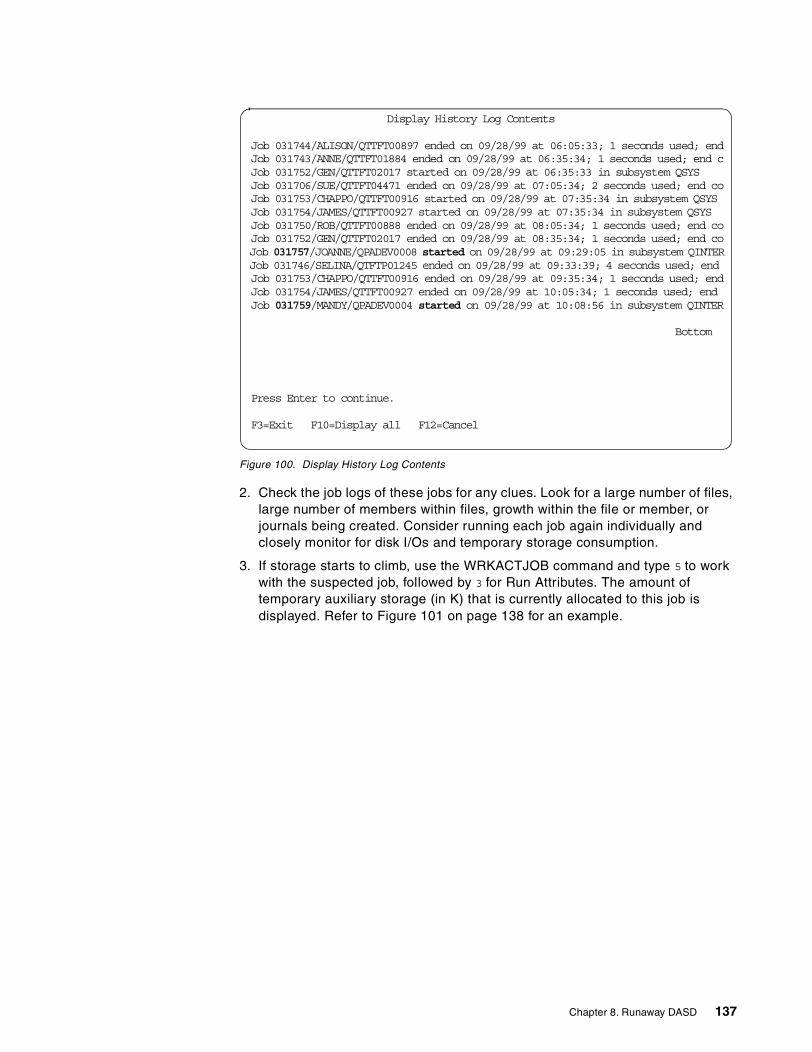
Figure 100. Display History Log Contents
2. Check the job logs of these jobs for any clues. Look for a large number of files,large number of members within files, growth within the file or member, orjournals being created. Consider running each job again individually andclosely monitor for disk I/Os and temporary storage consumption.
3. If storage starts to climb, use the WRKACTJOB command and type 5 to workwith the suspected job, followed by 3 for Run Attributes. The amount oftemporary auxiliary storage (in K) that is currently allocated to this job isdisplayed. Refer to Figure 101 on page 138 for an example.
Display History Log Contents
Job 031744/ALISON/QTTFT00897 ended on 09/28/99 at 06:05:33; 1 seconds used; endJob 031743/ANNE/QTTFT01884 ended on 09/28/99 at 06:35:34; 1 seconds used; end cJob 031752/GEN/QTTFT02017 started on 09/28/99 at 06:35:33 in subsystem QSYSJob 031706/SUE/QTTFT04471 ended on 09/28/99 at 07:05:34; 2 seconds used; end coJob 031753/CHAPPO/QTTFT00916 started on 09/28/99 at 07:35:34 in subsystem QSYSJob 031754/JAMES/QTTFT00927 started on 09/28/99 at 07:35:34 in subsystem QSYSJob 031750/ROB/QTTFT00888 ended on 09/28/99 at 08:05:34; 1 seconds used; end coJob 031752/GEN/QTTFT02017 ended on 09/28/99 at 08:35:34; 1 seconds used; end coJob 031757/JOANNE/QPADEV0008 started on 09/28/99 at 09:29:05 in subsystem QINTERJob 031746/SELINA/QTFTP01245 ended on 09/28/99 at 09:33:39; 4 seconds used; endJob 031753/CHAPPO/QTTFT00916 ended on 09/28/99 at 09:35:34; 1 seconds used; endJob 031754/JAMES/QTTFT00927 ended on 09/28/99 at 10:05:34; 1 seconds used; endJob 031759/MANDY/QPADEV0004 started on 09/28/99 at 10:08:56 in subsystem QINTER
Bottom
Press Enter to continue.
F3=Exit F10=Display all F12=Cancel
Chapter 8. Runaway DASD 137
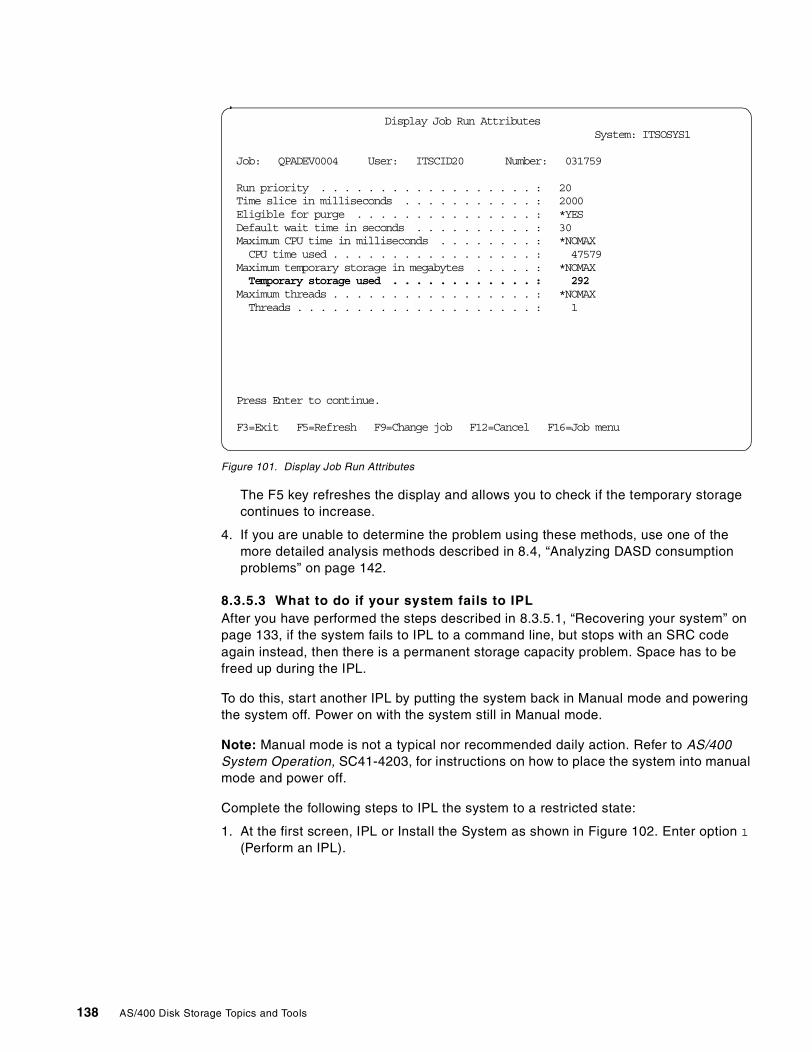
Figure 101. Display Job Run Attributes
The F5 key refreshes the display and allows you to check if the temporary storagecontinues to increase.
4. If you are unable to determine the problem using these methods, use one of themore detailed analysis methods described in 8.4, “Analyzing DASD consumptionproblems” on page 142.
8.3.5.3 What to do if your system fails to IPLAfter you have performed the steps described in 8.3.5.1, “Recovering your system” onpage 133, if the system fails to IPL to a command line, but stops with an SRC codeagain instead, then there is a permanent storage capacity problem. Space has to befreed up during the IPL.
To do this, start another IPL by putting the system back in Manual mode and poweringthe system off. Power on with the system still in Manual mode.
Note: Manual mode is not a typical nor recommended daily action. Refer to AS/400System Operation, SC41-4203, for instructions on how to place the system into manualmode and power off.
Complete the following steps to IPL the system to a restricted state:
1. At the first screen, IPL or Install the System as shown in Figure 102. Enter option 1
(Perform an IPL).
Display Job Run AttributesSystem: ITSOSYS1
Job: QPADEV0004 User: ITSCID20 Number: 031759
Run priority . . . . . . . . . . . . . . . . . . : 20Time slice in milliseconds . . . . . . . . . . . : 2000Eligible for purge . . . . . . . . . . . . . . . : *YESDefault wait time in seconds . . . . . . . . . . : 30Maximum CPU time in milliseconds . . . . . . . . : *NOMAXCPU time used . . . . . . . . . . . . . . . . . : 47579
Maximum temporary storage in megabytes . . . . . : *NOMAXTemporary storage used . . . . . . . . . . . . : 292
Maximum threads . . . . . . . . . . . . . . . . . : *NOMAXThreads . . . . . . . . . . . . . . . . . . . . : 1
Press Enter to continue.
F3=Exit F5=Refresh F9=Change job F12=Cancel F16=Job menu
138 AS/400 Disk Storage Topics and Tools
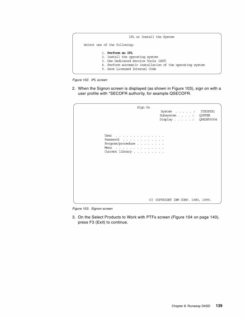
Figure 102. IPL screen
2. When the Signon screen is displayed (as shown in Figure 103), sign on with auser profile with *SECOFR authority, for example QSECOFR.
Figure 103. Signon screen
3. On the Select Products to Work with PTFs screen (Figure 104 on page 140),press F3 (Exit) to continue.
IPL or Install the System
Select one of the following:
1. Perform an IPL2. Install the operating system3. Use Dedicated Service Tools (DST)4. Perform automatic installation of the operating system5. Save Licensed Internal Code
Sign OnSystem . . . . . : ITSOSYS1Subsystem . . . . : QINTERDisplay . . . . . : QPADEV0004
User . . . . . . . . . . . . . .Password . . . . . . . . . . . .Program/procedure . . . . . . . .Menu . . . . . . . . . . . . . .Current library . . . . . . . . .
(C) COPYRIGHT IBM CORP. 1980, 1999.
Chapter 8. Runaway DASD 139
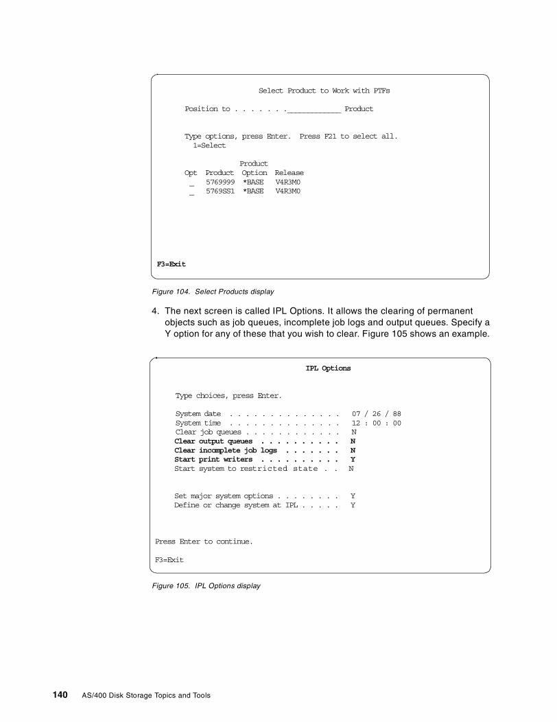
Figure 104. Select Products display
4. The next screen is called IPL Options. It allows the clearing of permanentobjects such as job queues, incomplete job logs and output queues. Specify aY option for any of these that you wish to clear. Figure 105 shows an example.
Figure 105. IPL Options display
Select Product to Work with PTFs
Position to . . . . . . ._____________ Product
Type options, press Enter. Press F21 to select all.1=Select
ProductOpt Product Option Release_ 5769999 *BASE V4R3M0_ 5769SS1 *BASE V4R3M0
F3=Exit
IPL Options
Type choices, press Enter.
System date . . . . . . . . . . . . . . 07 / 26 / 88System time . . . . . . . . . . . . . . 12 : 00 : 00Clear job queues . . . . . . . . . . . . NClear output queues . . . . . . . . . . NClear incomplete job logs . . . . . . . NStart print writers . . . . . . . . . . YStart system to restricted state . . N
Set major system options . . . . . . . . YDefine or change system at IPL . . . . . Y
Press Enter to continue.
F3=Exit
140 AS/400 Disk Storage Topics and Tools
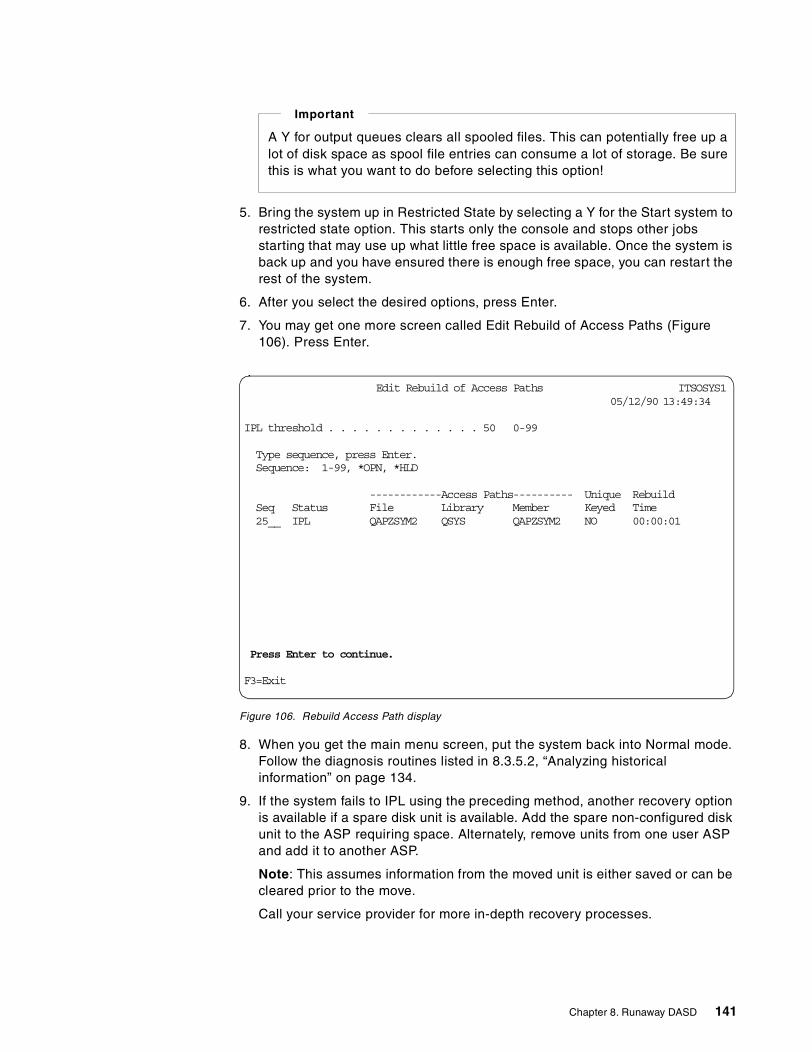
5. Bring the system up in Restricted State by selecting a Y for the Start system torestricted state option. This starts only the console and stops other jobsstarting that may use up what little free space is available. Once the system isback up and you have ensured there is enough free space, you can restart therest of the system.
6. After you select the desired options, press Enter.
7. You may get one more screen called Edit Rebuild of Access Paths (Figure106). Press Enter.
Figure 106. Rebuild Access Path display
8. When you get the main menu screen, put the system back into Normal mode.Follow the diagnosis routines listed in 8.3.5.2, “Analyzing historicalinformation” on page 134.
9. If the system fails to IPL using the preceding method, another recovery optionis available if a spare disk unit is available. Add the spare non-configured diskunit to the ASP requiring space. Alternately, remove units from one user ASPand add it to another ASP.
Note: This assumes information from the moved unit is either saved or can becleared prior to the move.
Call your service provider for more in-depth recovery processes.
A Y for output queues clears all spooled files. This can potentially free up alot of disk space as spool file entries can consume a lot of storage. Be surethis is what you want to do before selecting this option!
Important
| Edit Rebuild of Access Paths xxxxxxITSOSYS105/12/90 13:49:34
IPL threshold . . . . . . . . . . . . . 50 0-99
| Type sequence, press Enter.| Sequence: 1-99, *OPN, *HLD
| ------------Access Paths---------- Unique Rebuild| Seq Status File Library Member Keyed Time| 25__ IPL QAPZSYM2 QSYS QAPZSYM2 NO 00:00:01
Press Enter to continue.
F3=Exit
Chapter 8. Runaway DASD 141
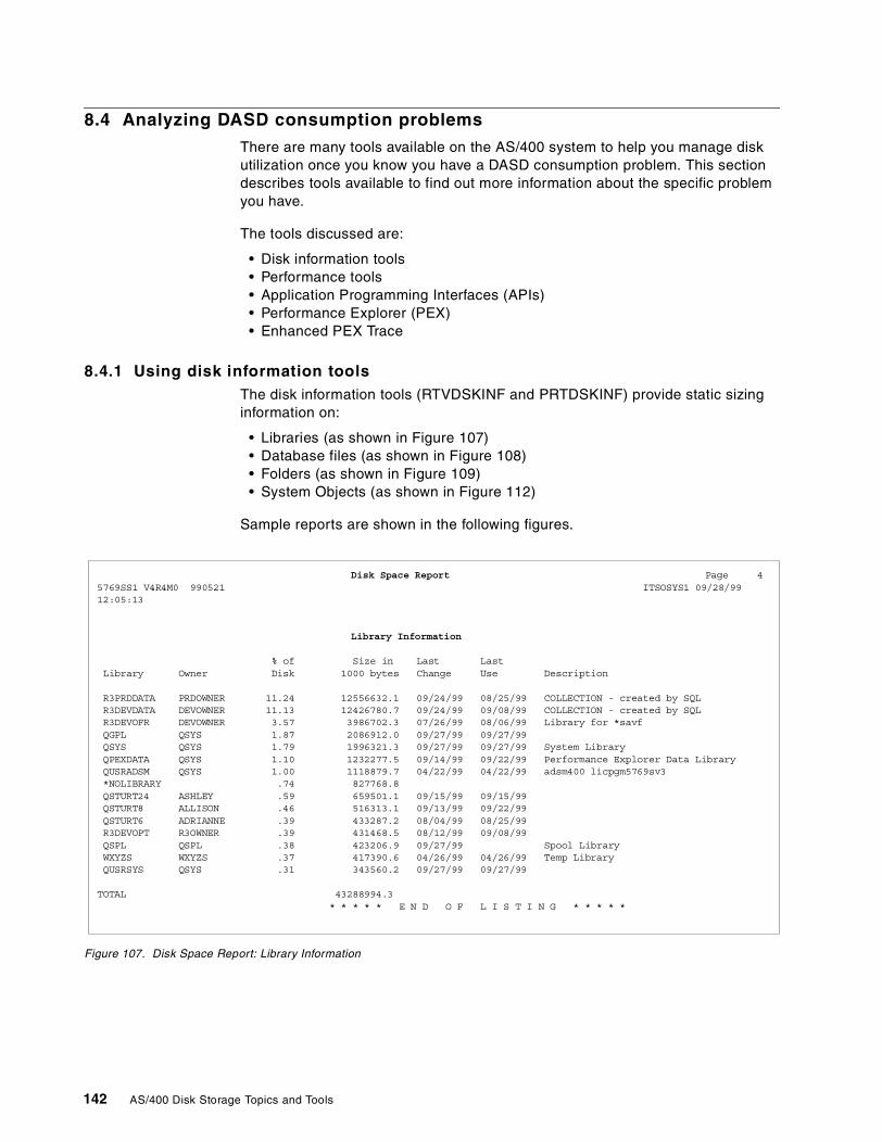
8.4 Analyzing DASD consumption problems
There are many tools available on the AS/400 system to help you manage diskutilization once you know you have a DASD consumption problem. This sectiondescribes tools available to find out more information about the specific problemyou have.
The tools discussed are:
• Disk information tools• Performance tools• Application Programming Interfaces (APIs)• Performance Explorer (PEX)• Enhanced PEX Trace
8.4.1 Using disk information toolsThe disk information tools (RTVDSKINF and PRTDSKINF) provide static sizinginformation on:
• Libraries (as shown in Figure 107)• Database files (as shown in Figure 108)• Folders (as shown in Figure 109)• System Objects (as shown in Figure 112)
Sample reports are shown in the following figures.
Figure 107. Disk Space Report: Library Information
Disk Space Report xxxxxxxxxxxxxxxxxxxxxxxxxxxxxxxxxxxxxxxxxxxPage 45769SS1 V4R4M0 990521 xxxxxxxxxxxxxxxxxxxxxxxxxxxxxxxxxxxxxxxxxxxxxxxxxxxxxxxxxxxxxxxxxxxxxxxITSOSYS1 09/28/9912:05:13
Library Information
% of Size in Last LastLibrary Owner Disk 1000 bytes Change Use Description
R3PRDDATA PRDOWNER 11.24 12556632.1 09/24/99 08/25/99 COLLECTION - created by SQLR3DEVDATA DEVOWNER 11.13 12426780.7 09/24/99 09/08/99 COLLECTION - created by SQLR3DEVOFR DEVOWNER 3.57 3986702.3 07/26/99 08/06/99 Library for *savfQGPL QSYS 1.87 2086912.0 09/27/99 09/27/99QSYS QSYS 1.79 1996321.3 09/27/99 09/27/99 System LibraryQPEXDATA QSYS 1.10 1232277.5 09/14/99 09/22/99 Performance Explorer Data LibraryQUSRADSM QSYS 1.00 1118879.7 04/22/99 04/22/99 adsm400 licpgm5769sv3*NOLIBRARY .74 827768.8QSTURT249999 ASHLEYE .59 659501.1 09/15/99 09/15/99QSTURT81KKKK ALLISON xxxxxxxxx.46 516313.1 09/13/99 09/22/99QSTURT6T ADRIANNExxxxxxxx .39 433287.2 08/04/99 08/25/99R3DEVOPT R3OWNER .39 431468.5 08/12/99 09/08/99QSPL QSPL .38 423206.9 09/27/99 Spool LibraryWXYZS WXYZS .37 417390.6 04/26/99 04/26/99 Temp LibraryQUSRSYS QSYS .31 343560.2 09/27/99 09/27/99
TOTAL 43288994.3* * * * * E N D O F L I S T I N G * * * * *
142 AS/400 Disk Storage Topics and Tools
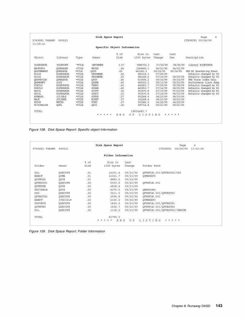
Figure 108. Disk Space Report: Specific object Information
Figure 109. Disk Space Report: Folder Information
Disk Space Report xxxxxxxxxxxxxxxxxxxxxxxxxxxxxxxxxxxxxxxxxxxxxxxPage 45769SS1 V4R4M0 990521 xxxxxxxxxxxxxxxxxxxxxxxxxxxxxxxxxxxxxxxxxxxxxxxxxxxxxxxxxxxxxxxxxxxxxxxITSOSYS1 09/28/9913:29:41
Specific Object Information
% of Size in Last LastObject Library Type Owner Disk 1000 bytes Change Use Description
R3DEVDATA R3DEVOFR *FILE DEVOWNER 3.57 3986702.3 07/26/99 08/06/99 Library R3DEVDATABACKUP01 QUSRADSM *FILE WXYZS .94 1049645.1 04/21/99 04/22/99QAYPEMBRKT QPEXDATA *FILE QSYS .59 661262.3 09/14/99 09/14/99 PEX MI Bracketing EventD010S R3DEVDATA *FILE DEVOWNER .52 585314.3 07/29/99 Defaults changed by R3D010S R3PRDDATA *FILE PRDOWNER .52 582168.6 07/14/99 08/25/99 Defaults changed by R3QAYPETIDX QPEXDATA *FILE QSYS .46 515506.2 09/14/99 09/14/99 PEX Trace Index DataQAPMDMPT LOCK *FILE QPGMR .40 448352.3 09/13/99 09/22/99 Performance trace dumpDOKCLU R3DEVDATA *FILE TERRYxER .40 445853.7 07/29/99 09/08/99 Defaults changed by R3DOKCLU R3PRDDATA *FILE SUSANNER .40 445853.7 07/14/99 08/25/99 Defaults changed by R3DD03L R3DEVDATA *FILE SCOTTNER .32 353570.8 07/19/99 07/22/99 Defaults changed by R3DD03L R3PRDDATA *FILE STACYNER .32 353570.8 07/14/99 08/03/99 Defaults changed by R3ACMEDS1 JJLIBLE *FILE STEVEGE .27 302268.4 08/23/99 08/23/99BACK JJLIBXE *FILE MIKETEE .27 302268.4 08/23/99 08/23/99FSIOP WXYZS *FILE TODDS .27 301482.0 04/22/99 04/22/99S5769AS1PA QGPL *FILE QSYI .26 295714.8 09/21/99 09/21/99
TOTAL 19836485.7* * * * * E N D O F L I S T I N G * * * * *
Disk Space Report Page 45769SS1 V4R4M0 990521 ITSOSYS1x 09/28/99 13:52:25
Folder Information
% of Size in LastFolder Owner Disk 1000 bytes Change Folder Path
DLL QSECOFR .01 14351.4 09/23/99 QFPBFLR.001/QFPBSYS2/OS2BBBDF QUMB .01 12361.7 09/23/99 QUMBREPOQSVNOS2 QSYS .01 8883.2 09/23/99QFPBSYS1 QSECOFR .00 5550.6 09/23/99 QFPBFLR.001QFPNTWE QSYS .00 4818.4 09/23/99UNITABLE QSYS .00 4075.5 09/23/99 QBKBOOKSOS2 QSECOFR .00 3411.5 09/23/99 QFPBFLR.001/QFPBSYS2QFPBSYS2 QSECOFR .00 2594.8 09/23/99 QFPBFLR.001BBBFF ITSCID19 .00 2190.3 09/26/99 QUMBREPOPSFONTS QSECOFR .00 1835.0 09/23/99 QFPBFLR.001/QFPBSYS1QFPNTWI QSECOFR .00 1606.7 09/23/99 QFPBFLR.001/QFPBSYS4DLL QSECOFR .00 1116.2 09/23/99 QFPBFLR.001/QFPBSYS2/IBMCOM
TOTAL 62795.3* * * * * E N D O F L I S T I N G * * * * *
Chapter 8. Runaway DASD 143
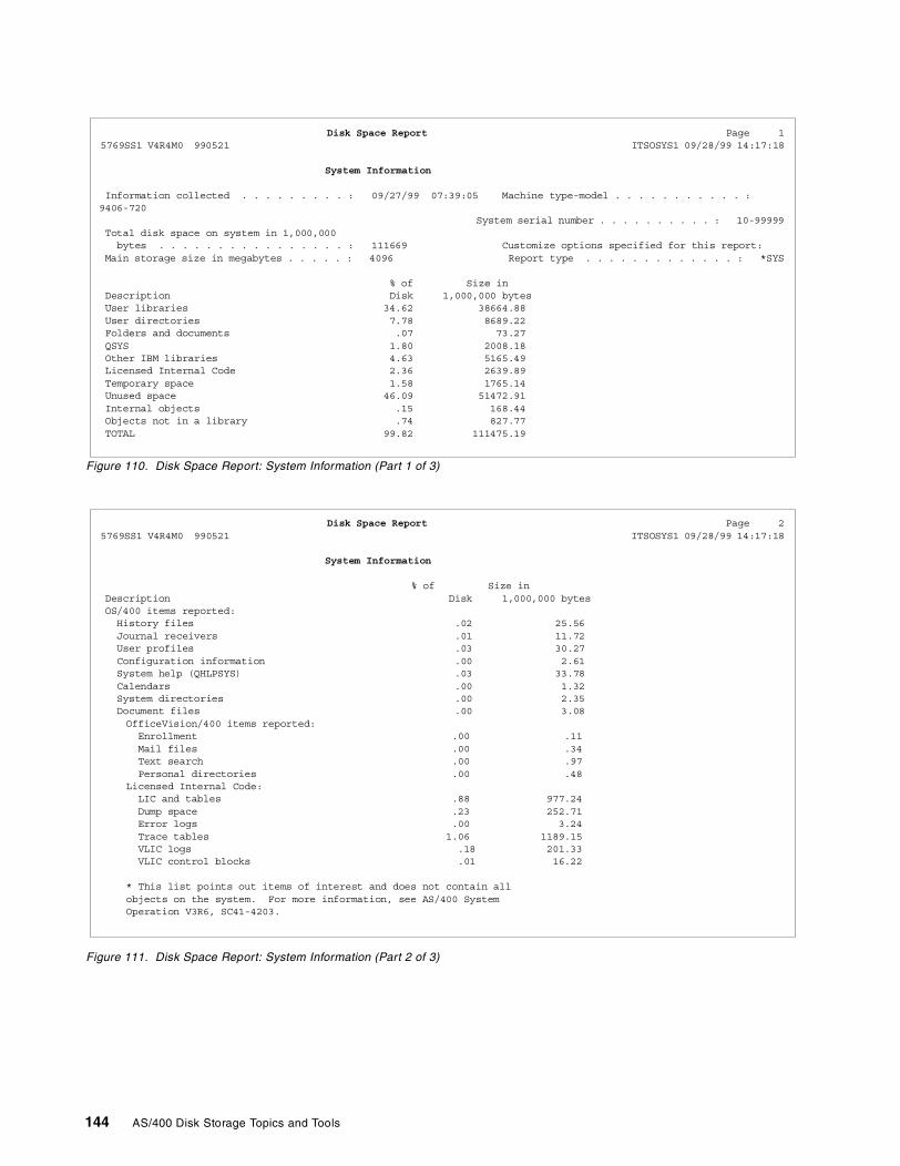
Figure 110. Disk Space Report: System Information (Part 1 of 3)
Figure 111. Disk Space Report: System Information (Part 2 of 3)
Disk Space Report xxxxxxxxxxxxxxxxxxxxxxxx Page 15769SS1 V4R4M0 990521 xxxxxxxxxxxxxx ITSOSYS1 09/28/99 14:17:18
System Information
Information collected . . . . . . . . . : 09/27/99 07:39:05 Machine type-model . . . . . . . . . . . :9406-720
System serial number . . . . . . . . . . : 10-99999Total disk space on system in 1,000,000bytes . . . . . . . . . . . . . . . . : 111669 Customize options specified for this report:
Main storage size in megabytes . . . . . : 4096 Report type . . . . . . . . . . . . . : *SYS
% of Size inDescription Disk 1,000,000 bytesUser libraries 34.62 38664.88User directories 7.78 8689.22Folders and documents .07 73.27QSYS 1.80 2008.18Other IBM libraries 4.63 5165.49Licensed Internal Code 2.36 2639.89Temporary space 1.58 1765.14Unused space 46.09 51472.91Internal objects .15 168.44Objects not in a library .74 827.77TOTAL 99.82 111475.19
Disk Space Report xxxxxxxxxxxxxxxxxxx Page 25769SS1 V4R4M0 990521 xxxxxxxx ITSOSYS1 09/28/99 14:17:18
System Information
% of Size inDescription Disk 1,000,000 bytesOS/400 items reported:History files .02 25.56Journal receivers .01 11.72User profiles .03 30.27Configuration information .00 2.61System help (QHLPSYS) .03 33.78Calendars .00 1.32System directories .00 2.35Document files .00 3.08OfficeVision/400 items reported:Enrollment .00 .11Mail files .00 .34Text search .00 .97Personal directories .00 .48
Licensed Internal Code:LIC and tables .88 977.24Dump space .23 252.71Error logs .00 3.24Trace tables 1.06 1189.15VLIC logs .18 201.33VLIC control blocks .01 16.22
* This list points out items of interest and does not contain allobjects on the system. For more information, see AS/400 SystemOperation V3R6, SC41-4203.
144 AS/400 Disk Storage Topics and Tools
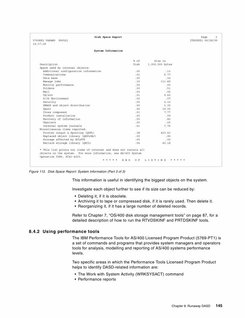
Figure 112. Disk Space Report: System Information (Part 3 of 3)
This information is useful in identifying the biggest objects on the system.
Investigate each object further to see if its size can be reduced by:
• Deleting it, if it is obsolete.• Archiving it to tape or compressed disk, if it is rarely used. Then delete it.• Reorganizing it, if it has a large number of deleted records.
Refer to Chapter 7, “OS/400 disk storage management tools” on page 87, for adetailed description of how to run the RTVDSKINF and PRTDSKINF tools.
8.4.2 Using performance toolsThe IBM Performance Tools for AS/400 Licensed Program Product (5769-PT1) isa set of commands and programs that provides system managers and operatorstools for analysis, modelling and reporting of AS/400 systems performancelevels.
Two specific areas in which the Performance Tools Licensed Program Producthelps to identify DASD-related information are:
• The Work with System Activity (WRKSYSACT) command• Performance reports
Disk Space Report Page 35769SS1 V4R4M0 990521 x ITSOSYS1 09/28/9914:17:18
System Information
% of Size inDescription Disk 1,000,000 bytesSpace used by internal objects:Additional configuration information .00 .13Communications .01 6.77Data base .00 .16Manage jobs .10 111.89Monitor performance .00 .00Folders .00 .51Mail .00 .02OS/400 .01 9.60S/36 Environment .00 .07Security .00 2.15SNADS and object distribution .00 1.35Spool .02 19.35Cross component .01 7.77Product installation .00 .09Recovery of information .00 .82Obsolete .00 .00Internal system journals .01 7.76
Miscellaneous items reported:Printer output & Spooling (QSPL) .38 423.43Replaced object library (QRPLOBJ) .00 .95Storage affected by RCLSTG .00 .00Reclaim storage library (QRCL) .04 40.18
* This list points out items of interest and does not contain allobjects on the system. For more information, see AS/400 SystemOperation V3R6, SC41-4203.
* * * * * E N D O F L I S T I N G * * * * *
Chapter 8. Runaway DASD 145
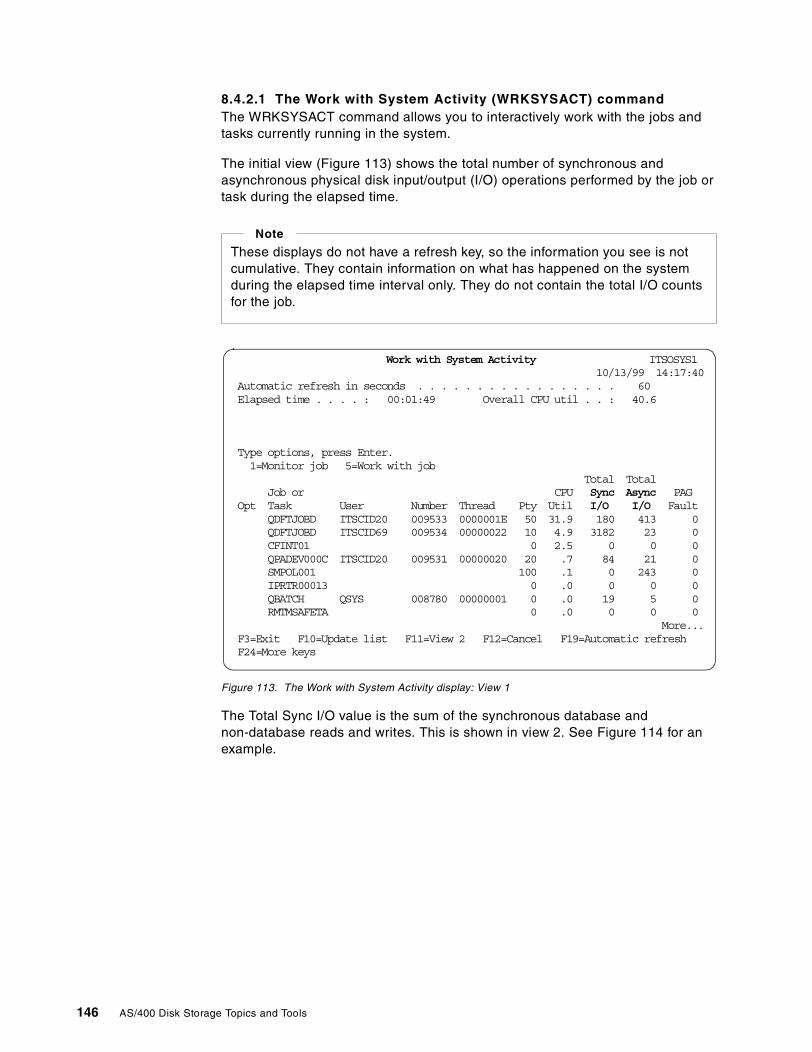
8.4.2.1 The Work with System Activity (WRKSYSACT) commandThe WRKSYSACT command allows you to interactively work with the jobs andtasks currently running in the system.
The initial view (Figure 113) shows the total number of synchronous andasynchronous physical disk input/output (I/O) operations performed by the job ortask during the elapsed time.
Figure 113. The Work with System Activity display: View 1
The Total Sync I/O value is the sum of the synchronous database andnon-database reads and writes. This is shown in view 2. See Figure 114 for anexample.
These displays do not have a refresh key, so the information you see is notcumulative. They contain information on what has happened on the systemduring the elapsed time interval only. They do not contain the total I/O countsfor the job.
Note
Work with System Activity ITSOSYS110/13/99 14:17:40
Automatic refresh in seconds . . . . . . . . . . . . . . . . . 60Elapsed time . . . . : 00:01:49 Overall CPU util . . : 40.6
Type options, press Enter.1=Monitor job 5=Work with job
Total TotalJob or CPU Sync Async PAG
Opt Task User Number Thread Pty Util I/O I/O FaultQDFTJOBD ITSCID20 009533 0000001E 50 31.9 180 413 0QDFTJOBD ITSCID69 xxx009534 00000022 10 4.9 3182 23 0CFINT01 0 2.5 0 0 0QPADEV000C ITSCID20 009531 00000020 20 .7 84 21 0SMPOL001 100 .1 0 243 0IPRTR00013 0 .0 0 0 0QBATCH QSYS 008780 00000001 0 .0 19 5 0RMTMSAFETA 0 .0 0 0 0
More...F3=Exit F10=Update list F11=View 2 F12=Cancel F19=Automatic refreshF24=More keys
146 AS/400 Disk Storage Topics and Tools
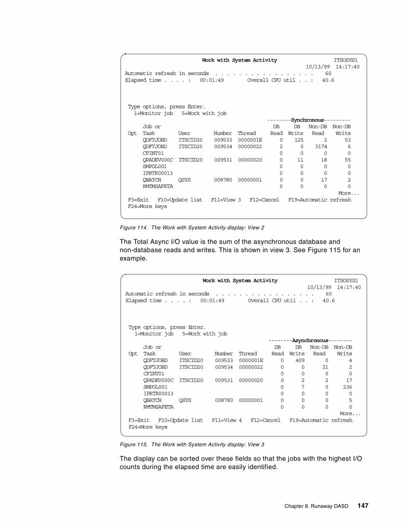
Figure 114. The Work with System Activity display: View 2
The Total Async I/O value is the sum of the asynchronous database andnon-database reads and writes. This is shown in view 3. See Figure 115 for anexample.
Figure 115. The Work with System Activity display: View 3
The display can be sorted over these fields so that the jobs with the highest I/Ocounts during the elapsed time are easily identified.
Work with System Activity ITSOSYS110/13/99 14:17:40
Automatic refresh in seconds . . . . . . . . . . . . . . . . . 60Elapsed time . . . . : 00:01:49 Overall CPU util . . : 40.6
Type options, press Enter.1=Monitor job 5=Work with job
--------Synchronous---------Job or DB DB Non-DB Non-DB
Opt Task User Number Thread Read Write Read WriteQDFTJOBD ITSCID20 009533 0000001E 0 125 2 53QDFTJOBD ITSCID20 009534 00000022 2 0 3174 6CFINT01 0 0 0 0QPADEV000C ITSCID20 009531 00000020 0 11 18 55SMPOL001 0 0 0 0IPRTR00013 0 0 0 0QBATCH QSYS 008780 00000001 0 0 17 2RMTMSAFETA 0 0 0 0
More...F3=Exit F10=Update list F11=View 3 F12=Cancel F19=Automatic refreshF24=More keys
Work with System Activity ITSOSYS110/13/99 14:17:40
Automatic refresh in seconds . . . . . . . . . . . . . . . . . 60Elapsed time . . . . : 00:01:49 Overall CPU util . . : 40.6
Type options, press Enter.1=Monitor job 5=Work with job
--------Asynchronous--------Job or DB DB Non-DB Non-DB
Opt Task User Number Thread Read Write Read WriteQDFTJOBD ITSCID20 009533 0000001E 0 409 0 4QDFTJOBD ITSCID20 009534 00000022 0 0 21 2CFINT01 0 0 0 0QPADEV000C ITSCID20 009531 00000020 0 2 2 17SMPOL001 0 7 0 236IPRTR00013 0 0 0 0QBATCH QSYS 008780 00000001 0 0 0 5RMTMSAFETA 0 0 0 0
More...F3=Exit F10=Update list F11=View 4 F12=Cancel F19=Automatic refreshF24=More keys
Chapter 8. Runaway DASD 147
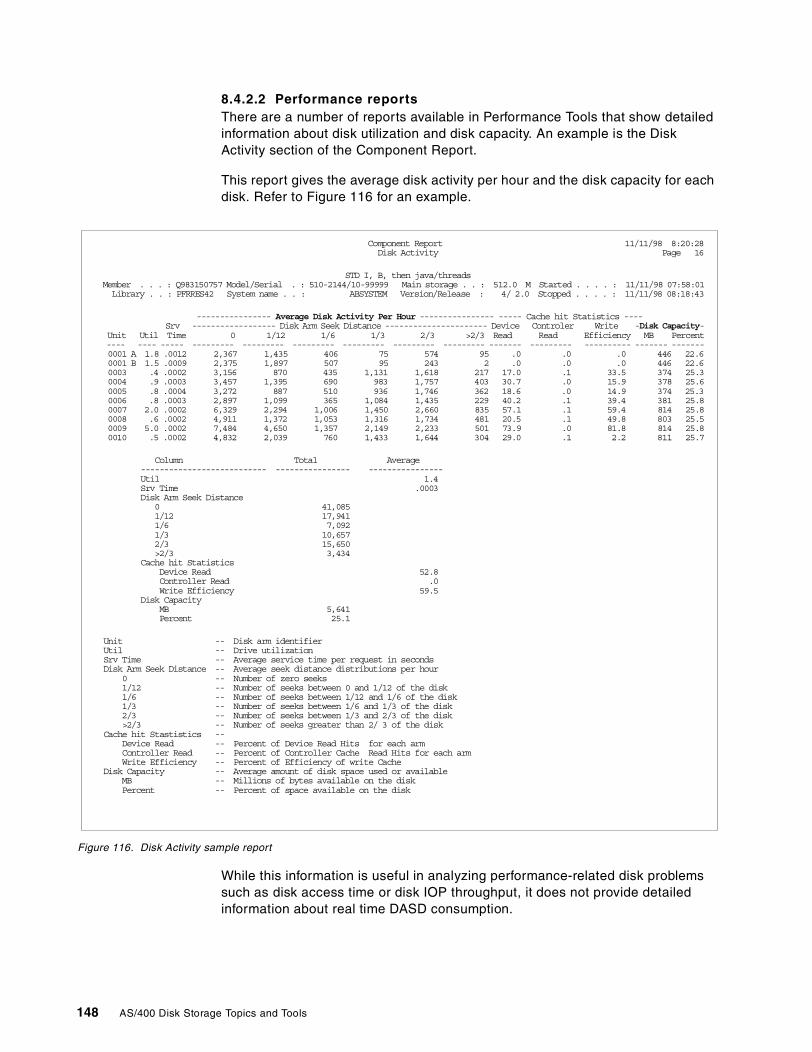
8.4.2.2 Performance reportsThere are a number of reports available in Performance Tools that show detailedinformation about disk utilization and disk capacity. An example is the DiskActivity section of the Component Report.
This report gives the average disk activity per hour and the disk capacity for eachdisk. Refer to Figure 116 for an example.
Figure 116. Disk Activity sample report
While this information is useful in analyzing performance-related disk problemssuch as disk access time or disk IOP throughput, it does not provide detailedinformation about real time DASD consumption.
Component Report 11/11/98 8:20:28Disk Activity Page 16
STD I, B, then java/threadsMember . . . : Q983150757 Model/Serial . : 510-2144/10-99999xx Main storage . . : 512.0 M Started . . . . : 11/11/98 07:58:01Library . . : PFRRES42 System name . . : ABSYSTEM Version/Release : 4/ 2.0 Stopped . . . . : 11/11/98 08:18:43
---------------- Average Disk Activity Per Hour ---------------- ----- Cache hit Statistics ----Srv ------------------ Disk Arm Seek Distance ---------------------- Device Controler Write -Disk Capacity-
Unit Util Time 0 1/12 1/6 1/3 2/3 >2/3 Read Read Efficiency MB Percent---- ---- ----- --------- --------- --------- --------- --------- --------- ------- --------- ---------- ------- -------0001 A 1.8 .0012 2,367 1,435 406 75 574 95 .0 .0 .0 446 22.60001 B 1.5 .0009 2,375 1,897 507 95 243 2 .0 .0 .0 446 22.60003 .4 .0002 3,156 870 435 1,131 1,618 217 17.0 .1 33.5 374 25.30004 .9 .0003 3,457 1,395 690 983 1,757 403 30.7 .0 15.9 378 25.60005 .8 .0004 3,272 887 510 936 1,746 362 18.6 .0 14.9 374 25.30006 .8 .0003 2,897 1,099 365 1,084 1,435 229 40.2 .1 39.4 381 25.80007 2.0 .0002 6,329 2,294 1,006 1,450 2,660 835 57.1 .1 59.4 814 25.80008 .6 .0002 4,911 1,372 1,053 1,316 1,734 481 20.5 .1 49.8 803 25.50009 5.0 .0002 7,484 4,650 1,357 2,149 2,233 501 73.9 .0 81.8 814 25.80010 .5 .0002 4,832 2,039 760 1,433 1,644 304 29.0 .1 2.2 811 25.7
Column Total Average--------------------------- ---------------- ----------------Util 1.4Srv Time .0003Disk Arm Seek Distance
0 41,0851/12 17,9411/6 7,0921/3 10,6572/3 15,650>2/3 3,434
Cache hit StatisticsDevice Read 52.8Controller Read .0Write Efficiency 59.5
Disk CapacityMB 5,641Percent 25.1
Unit -- Disk arm identifierUtil -- Drive utilizationSrv Time -- Average service time per request in secondsDisk Arm Seek Distance -- Average seek distance distributions per hour
0 -- Number of zero seeks1/12 -- Number of seeks between 0 and 1/12 of the disk1/6 -- Number of seeks between 1/12 and 1/6 of the disk1/3 -- Number of seeks between 1/6 and 1/3 of the disk2/3 -- Number of seeks between 1/3 and 2/3 of the disk>2/3 -- Number of seeks greater than 2/ 3 of the disk
Cache hit Stastistics --Device Read -- Percent of Device Read Hits for each armController Read -- Percent of Controller Cache Read Hits for each armWrite Efficiency -- Percent of Efficiency of write Cache
Disk Capacity -- Average amount of disk space used or availableMB -- Millions of bytes available on the diskPercent -- Percent of space available on the disk
148 AS/400 Disk Storage Topics and Tools
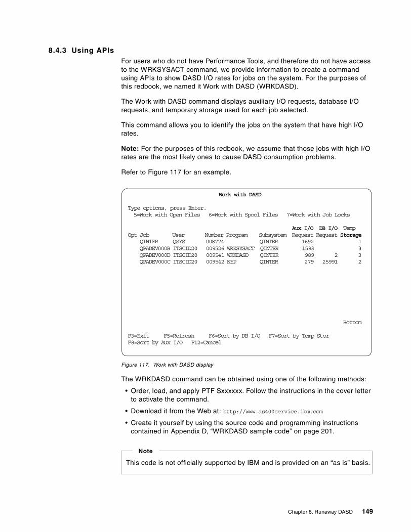
8.4.3 Using APIsFor users who do not have Performance Tools, and therefore do not have accessto the WRKSYSACT command, we provide information to create a commandusing APIs to show DASD I/O rates for jobs on the system. For the purposes ofthis redbook, we named it Work with DASD (WRKDASD).
The Work with DASD command displays auxiliary I/O requests, database I/Orequests, and temporary storage used for each job selected.
This command allows you to identify the jobs on the system that have high I/Orates.
Note: For the purposes of this redbook, we assume that those jobs with high I/Orates are the most likely ones to cause DASD consumption problems.
Refer to Figure 117 for an example.
Figure 117. Work with DASD display
The WRKDASD command can be obtained using one of the following methods:
• Order, load, and apply PTF Sxxxxxx. Follow the instructions in the cover letterto activate the command.
• Download it from the Web at: http://www.as400service.ibm.com
• Create it yourself by using the source code and programming instructionscontained in Appendix D, “WRKDASD sample code” on page 201.
Work with DASD
Type options, press Enter.5=Work with Open Files 6=Work with Spool Files 7=Work with Job Locks
Aux I/O DB I/O TempOpt Job User Number Program Subsystem Request Request Storage
QINTER QSYS 008774 QINTER 1692 1QPADEV000B ITSCID20 009526 WRKSYSACT QINTER 1593 3QPADEV000D ITSCID20 009541 WRKDASD QINTER 989 2 3QPADEV000C ITSCID20 009542 NEP QINTER 279 25991 2
Bottom
F3=Exit F5=Refresh F6=Sort by DB I/O F7=Sort by Temp StorF8=Sort by Aux I/O F12=Cancel
This code is not officially supported by IBM and is provided on an “as is” basis.
Note
Chapter 8. Runaway DASD 149
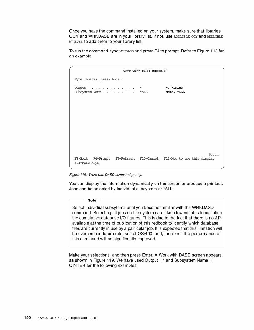
Once you have the command installed on your system, make sure that librariesQGY and WRKDASD are in your library list. If not, use ADDLIBLE QGY and ADDLIBLE
WRKDASD to add them to your library list.
To run the command, type WRKDASD and press F4 to prompt. Refer to Figure 118 foran example.
Figure 118. Work with DASD command prompt
You can display the information dynamically on the screen or produce a printout.Jobs can be selected by individual subsystem or *ALL.
Make your selections, and then press Enter. A Work with DASD screen appears,as shown in Figure 119. We have used Output = * and Subsystem Name =QINTER for the following examples.
Work with DASD (WRKDASD)
Type choices, press Enter.
Output . . . . . . . . . . . . . * *, *PRINTSubsystem Name . . . . . . . . . *ALL Name, *ALL
BottomF3=Exit F4=Prompt F5=Refresh F12=Cancel F13=How to use this displayF24=More keys
Select individual subsytems until you become familiar with the WRKDASDcommand. Selecting all jobs on the system can take a few minutes to calculatethe cumulative database I/O figures. This is due to the fact that there is no APIavailable at the time of publication of this redbook to identify which databasefiles are currently in use by a particular job. It is expected that this limitation willbe overcome in future releases of OS/400, and, therefore, the performance ofthis command will be significantly improved.
Note
150 AS/400 Disk Storage Topics and Tools
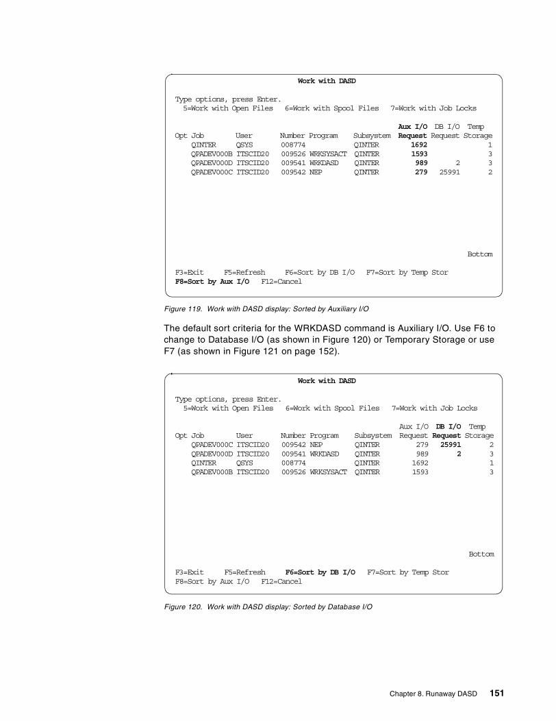
Figure 119. Work with DASD display: Sorted by Auxiliary I/O
The default sort criteria for the WRKDASD command is Auxiliary I/O. Use F6 tochange to Database I/O (as shown in Figure 120) or Temporary Storage or useF7 (as shown in Figure 121 on page 152).
Figure 120. Work with DASD display: Sorted by Database I/O
Work with DASD
Type options, press Enter.5=Work with Open Files 6=Work with Spool Files 7=Work with Job Locks
Aux I/O DB I/O TempOpt Job User Number Program Subsystem Request Request Storage
QINTER QSYS 008774 QINTER 1692 1QPADEV000B ITSCID20 009526 WRKSYSACT QINTER 1593 3QPADEV000D ITSCID20 009541 WRKDASD QINTER 989 2 3QPADEV000C ITSCID20 009542 NEP QINTER 279 25991 2
Bottom
F3=Exit F5=Refresh F6=Sort by DB I/O F7=Sort by Temp StorF8=Sort by Aux I/O F12=Cancel
Work with DASD
Type options, press Enter.5=Work with Open Files 6=Work with Spool Files 7=Work with Job Locks
Aux I/O DB I/O TempOpt Job User Number Program Subsystem Request Request Storage
QPADEV000C ITSCID20 009542 NEP QINTER 279 25991 2QPADEV000D ITSCID20 009541 WRKDASD QINTER 989 2 3QINTER QSYS 008774 QINTER 1692 1QPADEV000B ITSCID20 009526 WRKSYSACT QINTER 1593 3
Bottom
F3=Exit F5=Refresh F6=Sort by DB I/O F7=Sort by Temp StorF8=Sort by Aux I/O F12=Cancel
Chapter 8. Runaway DASD 151
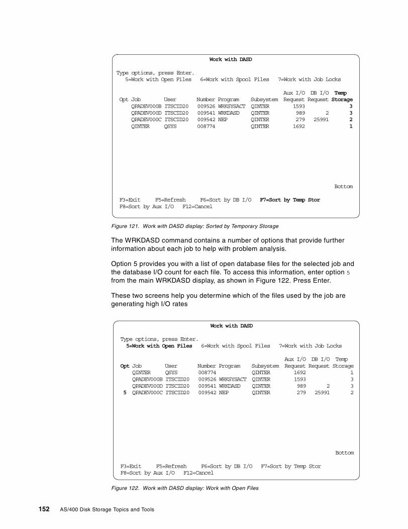
Figure 121. Work with DASD display: Sorted by Temporary Storage
The WRKDASD command contains a number of options that provide furtherinformation about each job to help with problem analysis.
Option 5 provides you with a list of open database files for the selected job andthe database I/O count for each file. To access this information, enter option 5
from the main WRKDASD display, as shown in Figure 122. Press Enter.
These two screens help you determine which of the files used by the job aregenerating high I/O rates
Figure 122. Work with DASD display: Work with Open Files
Work with DASD
Type options, press Enter.5=Work with Open Files 6=Work with Spool Files 7=Work with Job Locks
Aux I/O DB I/O TempOpt Job User Number Program Subsystem Request Request Storage
QPADEV000B ITSCID20 009526 WRKSYSACT QINTER 1593 3QPADEV000D ITSCID20 009541 WRKDASD QINTER 989 2 3QPADEV000C ITSCID20 009542 NEP QINTER 279 25991 2QINTER QSYS 008774 QINTER 1692 1
Bottom
F3=Exit F5=Refresh F6=Sort by DB I/O F7=Sort by Temp StorF8=Sort by Aux I/O F12=Cancel
Work with DASD
Type options, press Enter.5=Work with Open Files 6=Work with Spool Files 7=Work with Job Locks
Aux I/O DB I/O TempOpt Job User Number Program Subsystem Request Request Storage
QINTER QSYS 008774 QINTER 1692 1QPADEV000B ITSCID20 009526 WRKSYSACT QINTER 1593 3QPADEV000D ITSCID20 009541 WRKDASD QINTER 989 2 3
5 xQPADEV000C ITSCID20 009542 NEP QINTER 279 25991 2
Bottom
F3=Exit F5=Refresh F6=Sort by DB I/O F7=Sort by Temp StorF8=Sort by Aux I/O F12=Cancel
152 AS/400 Disk Storage Topics and Tools
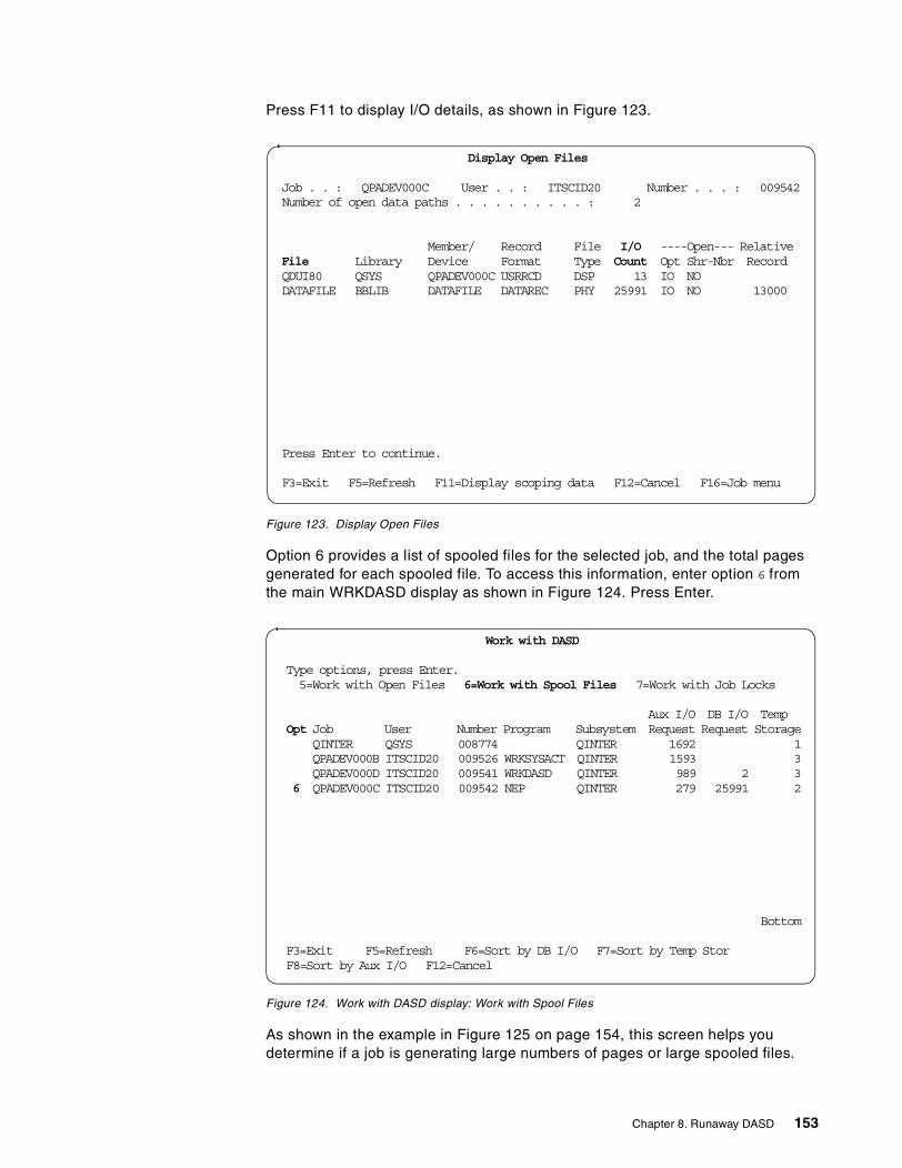
Press F11 to display I/O details, as shown in Figure 123.
Figure 123. Display Open Files
Option 6 provides a list of spooled files for the selected job, and the total pagesgenerated for each spooled file. To access this information, enter option 6 fromthe main WRKDASD display as shown in Figure 124. Press Enter.
Figure 124. Work with DASD display: Work with Spool Files
As shown in the example in Figure 125 on page 154, this screen helps youdetermine if a job is generating large numbers of pages or large spooled files.
Display Open Files
Job . . : QPADEV000C User . . : ITSCID20 Number . . . : 009542Number of open data paths . . . . . . . . . . : 2
Member/ Record File I/O ----Open--- RelativeFile Library Device Format Type Count Opt Shr-Nbr RecordQDUI80 QSYS QPADEV000C USRRCD DSP 13 IO NODATAFILE BBLIB DATAFILE DATAREC PHY 25991 IO NO 13000
Press Enter to continue.
F3=Exit F5=Refresh F11=Display scoping data F12=Cancel F16=Job menu
Work with DASD
Type options, press Enter.5=Work with Open Files 6=Work with Spool Files 7=Work with Job Locks
Aux I/O DB I/O TempOpt Job User Number Program Subsystem Request Request Storage
QINTER QSYS 008774 QINTER 1692 1QPADEV000B ITSCID20 009526 WRKSYSACT QINTER 1593 3QPADEV000D ITSCID20 009541 WRKDASD QINTER 989 2 3
6 xQPADEV000C ITSCID20 009542 NEP QINTER 279 25991 2
Bottom
F3=Exit F5=Refresh F6=Sort by DB I/O F7=Sort by Temp StorF8=Sort by Aux I/O F12=Cancel
Chapter 8. Runaway DASD 153
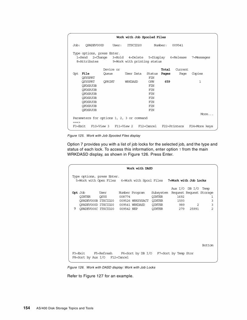
Figure 125. Work with Job Spooled Files display
Option 7 provides you with a list of job locks for the selected job, and the type andstatus of each lock. To access this information, enter option 7 from the mainWRKDASD display, as shown in Figure 126. Press Enter.
Figure 126. Work with DASD display: Work with Job Locks
Refer to Figure 127 for an example.
Work with Job Spooled Files
Job: QPADEV000D User: ITSCID20 Number: 009541
Type options, press Enter.1=Send 2=Change 3=Hold 4=Delete 5=Display 6=Release 7=Messages8=Attributes 9=Work with printing status
Device or Total CurrentOpt File Queue User Data Status Pages Page Copies
QSYSPRT FINQSYSPRT QPRINT WRKDASD OPN 659xxxxxxxxxxxxxxx 1QPDSPJOB FINQPDSPJOB FINQPDSPJOB FINQPDSPJOB FINQPDSPJOB FINQPDSPJOB FINQPDSPJOB FIN
More...Parameters for options 1, 2, 3 or command===>F3=Exit F10=View 3 F11=View 2 F12=Cancel F22=Printers F24=More keys
Work with DASD
Type options, press Enter.5=Work with Open Files 6=Work with Spool Files 7=Work with Job Locks
Aux I/O DB I/O TempOpt Job User Number Program Subsystem Request Request Storage
QINTER QSYS 008774 QINTER 1692 1QPADEV000B ITSCID20 009526 WRKSYSACT QINTER 1593 3QPADEV000D ITSCID20 009541 WRKDASD QINTER 989 2 3
7 xQPADEV000C ITSCID20 009542 NEP QINTER 279 25991 2
Bottom
F3=Exit F5=Refresh F6=Sort by DB I/O F7=Sort by Temp StorF8=Sort by Aux I/O F12=Cancel
154 AS/400 Disk Storage Topics and Tools
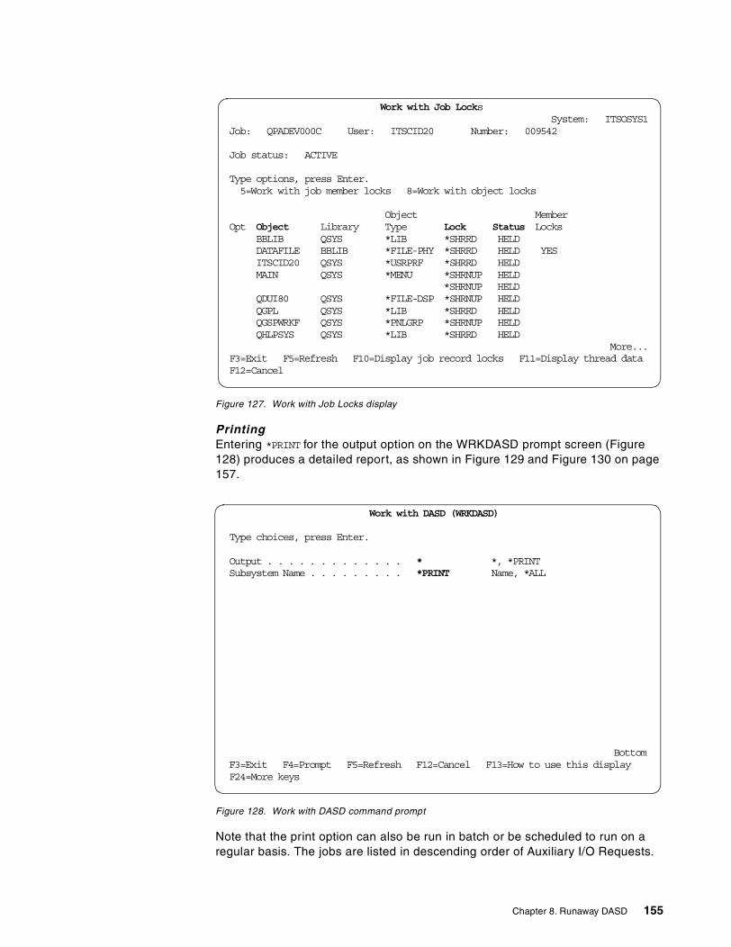
Figure 127. Work with Job Locks display
PrintingEntering *PRINT for the output option on the WRKDASD prompt screen (Figure128) produces a detailed report, as shown in Figure 129 and Figure 130 on page157.
Figure 128. Work with DASD command prompt
Note that the print option can also be run in batch or be scheduled to run on aregular basis. The jobs are listed in descending order of Auxiliary I/O Requests.
Work with Job LocksSystem: ITSOSYS1
Job: QPADEV000C User: ITSCID20 Number: 009542
Job status: ACTIVE
Type options, press Enter.5=Work with job member locks 8=Work with object locks
Object MemberOpt Object Library Type Lock Status Locks
BBLIB QSYS *LIB *SHRRD HELDDATAFILE BBLIB *FILE-PHY *SHRRD HELD YESITSCID20 QSYS *USRPRF *SHRRD HELDMAIN QSYS *MENU *SHRNUP HELD
*SHRNUP HELDQDUI80 QSYS *FILE-DSP *SHRNUP HELDQGPL QSYS *LIB *SHRRD HELDQGSPWRKF QSYS *PNLGRP *SHRNUP HELDQHLPSYS QSYS *LIB *SHRRD HELD
More...F3=Exit F5=Refresh F10=Display job record locks F11=Display thread dataF12=Cancel
Work with DASD (WRKDASD)
Type choices, press Enter.
Output . . . . . . . . . . . . . * *, *PRINTSubsystem Name . . . . . . . . . *PRINT xxxxxx Name, *ALL
BottomF3=Exit F4=Prompt F5=Refresh F12=Cancel F13=How to use this displayF24=More keys
Chapter 8. Runaway DASD 155
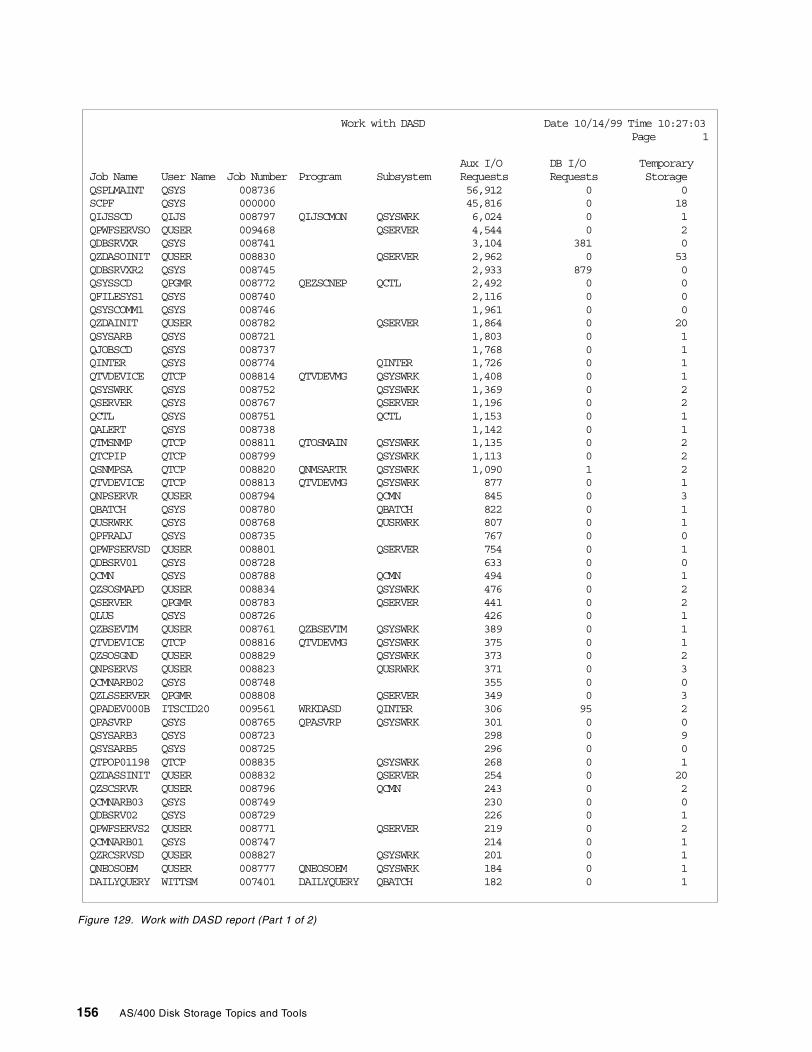
Figure 129. Work with DASD report (Part 1 of 2)
Work with DASD Date 10/14/99 Time 10:27:03Page 1
Aux I/O DB I/O TemporaryJob Name User Name Job Number Program Subsystem Requests Requests StorageQSPLMAINT QSYS 008736 56,912 0 0SCPF QSYS 000000 45,816 0 18QIJSSCD QIJS 008797 QIJSCMON QSYSWRK 6,024 0 1QPWFSERVSO QUSER 009468 QSERVER 4,544 0 2QDBSRVXR QSYS 008741 3,104 381 0QZDASOINIT QUSER 008830 QSERVER 2,962 0 53QDBSRVXR2 QSYS 008745 2,933 879 0QSYSSCD QPGMR 008772 QEZSCNEP QCTL 2,492 0 0QFILESYS1 QSYS 008740 2,116 0 0QSYSCOMM1 QSYS 008746 1,961 0 0QZDAINIT QUSER 008782 QSERVER 1,864 0 20QSYSARB QSYS 008721 1,803 0 1QJOBSCD QSYS 008737 1,768 0 1QINTER QSYS 008774 QINTER 1,726 0 1QTVDEVICE QTCP 008814 QTVDEVMG QSYSWRK 1,408 0 1QSYSWRK QSYS 008752 QSYSWRK 1,369 0 2QSERVER QSYS 008767 QSERVER 1,196 0 2QCTL QSYS 008751 QCTL 1,153 0 1QALERT QSYS 008738 1,142 0 1QTMSNMP QTCP 008811 QTOSMAIN QSYSWRK 1,135 0 2QTCPIP QTCP 008799 QSYSWRK 1,113 0 2QSNMPSA QTCP 008820 QNMSARTR QSYSWRK 1,090 1 2QTVDEVICE QTCP 008813 QTVDEVMG QSYSWRK 877 0 1QNPSERVR QUSER 008794 QCMN 845 0 3QBATCH QSYS 008780 QBATCH 822 0 1QUSRWRK QSYS 008768 QUSRWRK 807 0 1QPFRADJ QSYS 008735 767 0 0QPWFSERVSD QUSER 008801 QSERVER 754 0 1QDBSRV01 QSYS 008728 633 0 0QCMN QSYS 008788 QCMN 494 0 1QZSOSMAPD QUSER 008834 QSYSWRK 476 0 2QSERVER QPGMR 008783 QSERVER 441 0 2QLUS QSYS 008726 426 0 1QZBSEVTM QUSER 008761 QZBSEVTM QSYSWRK 389 0 1QTVDEVICE QTCP 008816 QTVDEVMG QSYSWRK 375 0 1QZSOSGND QUSER 008829 QSYSWRK 373 0 2QNPSERVS QUSER 008823 QUSRWRK 371 0 3QCMNARB02 QSYS 008748 355 0 0QZLSSERVER QPGMR 008808 QSERVER 349 0 3QPADEV000B ITSCID20 009561 WRKDASD QINTER 306 95 2QPASVRP QSYS 008765 QPASVRP QSYSWRK 301 0 0QSYSARB3 QSYS 008723 298 0 9QSYSARB5 QSYS 008725 296 0 0QTPOP01198 QTCP 008835 QSYSWRK 268 0 1QZDASSINIT QUSER 008832 QSERVER 254 0 20QZSCSRVR QUSER 008796 QCMN 243 0 2QCMNARB03 QSYS 008749 230 0 0QDBSRV02 QSYS 008729 226 0 1QPWFSERVS2 QUSER 008771 QSERVER 219 0 2QCMNARB01 QSYS 008747 214 0 1QZRCSRVSD QUSER 008827 QSYSWRK 201 0 1QNEOSOEM QUSER 008777 QNEOSOEM QSYSWRK 184 0 1DAILYQUERY WITTSM 007401 DAILYQUERY QBATCH 182 0 1
156 AS/400 Disk Storage Topics and Tools
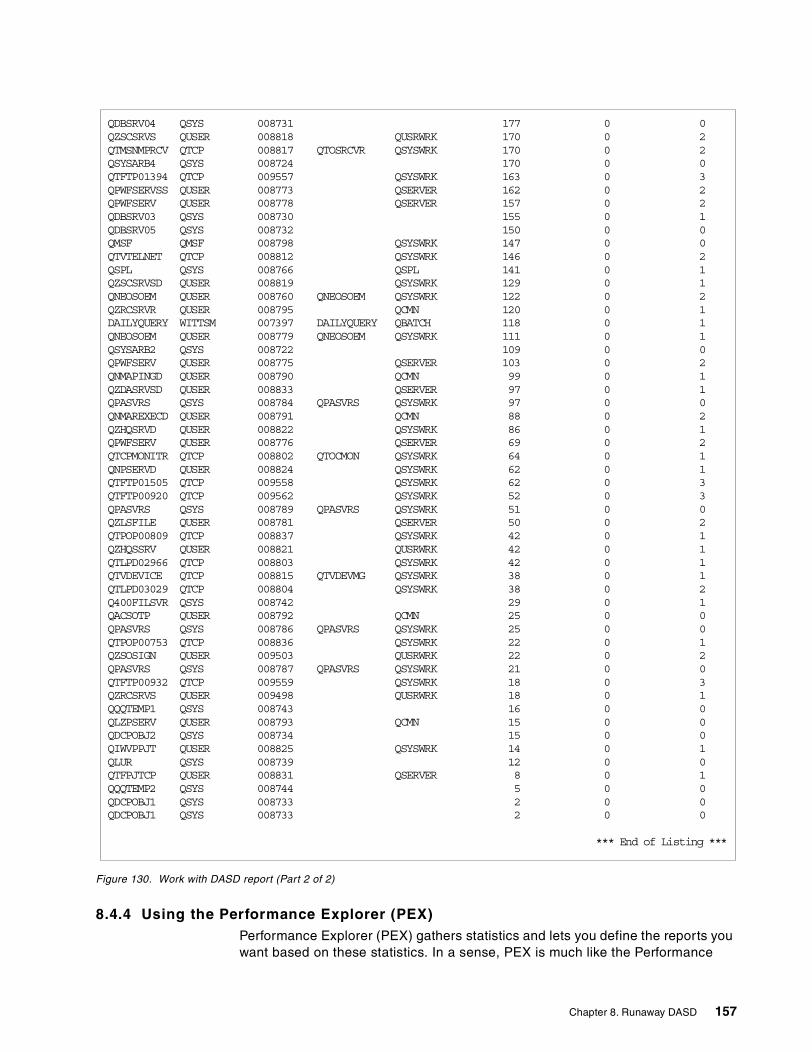
Figure 130. Work with DASD report (Part 2 of 2)
8.4.4 Using the Performance Explorer (PEX)Performance Explorer (PEX) gathers statistics and lets you define the reports youwant based on these statistics. In a sense, PEX is much like the Performance
QDBSRV04 QSYS 008731 177 0 0QZSCSRVS QUSER 008818 QUSRWRK 170 0 2QTMSNMPRCV QTCP 008817 QTOSRCVR QSYSWRK 170 0 2QSYSARB4 QSYS 008724 170 0 0QTFTP01394 QTCP 009557 QSYSWRK 163 0 3QPWFSERVSS QUSER 008773 QSERVER 162 0 2QPWFSERV QUSER 008778 QSERVER 157 0 2QDBSRV03 QSYS 008730 155 0 1QDBSRV05 QSYS 008732 150 0 0QMSF QMSF 008798 QSYSWRK 147 0 0QTVTELNET QTCP 008812 QSYSWRK 146 0 2QSPL QSYS 008766 QSPL 141 0 1QZSCSRVSD QUSER 008819 QSYSWRK 129 0 1QNEOSOEM QUSER 008760 QNEOSOEM QSYSWRK 122 0 2QZRCSRVR QUSER 008795 QCMN 120 0 1DAILYQUERY WITTSM 007397 DAILYQUERY QBATCH 118 0 1QNEOSOEM QUSER 008779 QNEOSOEM QSYSWRK 111 0 1QSYSARB2 QSYS 008722 109 0 0QPWFSERV QUSER 008775 QSERVER 103 0 2QNMAPINGD QUSER 008790 QCMN 99 0 1QZDASRVSD QUSER 008833 QSERVER 97 0 1QPASVRS QSYS 008784 QPASVRS QSYSWRK 97 0 0QNMAREXECD QUSER 008791 QCMN 88 0 2QZHQSRVD QUSER 008822 QSYSWRK 86 0 1QPWFSERV QUSER 008776 QSERVER 69 0 2QTCPMONITR QTCP 008802 QTOCMON QSYSWRK 64 0 1QNPSERVD QUSER 008824 QSYSWRK 62 0 1QTFTP01505 QTCP 009558 QSYSWRK 62 0 3QTFTP00920 QTCP 009562 QSYSWRK 52 0 3QPASVRS QSYS 008789 QPASVRS QSYSWRK 51 0 0QZLSFILE QUSER 008781 QSERVER 50 0 2QTPOP00809 QTCP 008837 QSYSWRK 42 0 1QZHQSSRV QUSER 008821 QUSRWRK 42 0 1QTLPD02966 QTCP 008803 QSYSWRK 42 0 1QTVDEVICE QTCP 008815 QTVDEVMG QSYSWRK 38 0 1QTLPD03029 QTCP 008804 QSYSWRK 38 0 2Q400FILSVR QSYS 008742 29 0 1QACSOTP QUSER 008792 QCMN 25 0 0QPASVRS QSYS 008786 QPASVRS QSYSWRK 25 0 0QTPOP00753 QTCP 008836 QSYSWRK 22 0 1QZSOSIGN QUSER 009503 QUSRWRK 22 0 2QPASVRS QSYS 008787 QPASVRS QSYSWRK 21 0 0QTFTP00932 QTCP 009559 QSYSWRK 18 0 3QZRCSRVS QUSER 009498 QUSRWRK 18 0 1QQQTEMP1 QSYS 008743 16 0 0QLZPSERV QUSER 008793 QCMN 15 0 0QDCPOBJ2 QSYS 008734 15 0 0QIWVPPJT QUSER 008825 QSYSWRK 14 0 1QLUR QSYS 008739 12 0 0QTFPJTCP QUSER 008831 QSERVER 8 0 1QQQTEMP2 QSYS 008744 5 0 0QDCPOBJ1 QSYS 008733 2 0 0QDCPOBJ1 QSYS 008733 2 0 0
*** End of Listing ***
Chapter 8. Runaway DASD 157
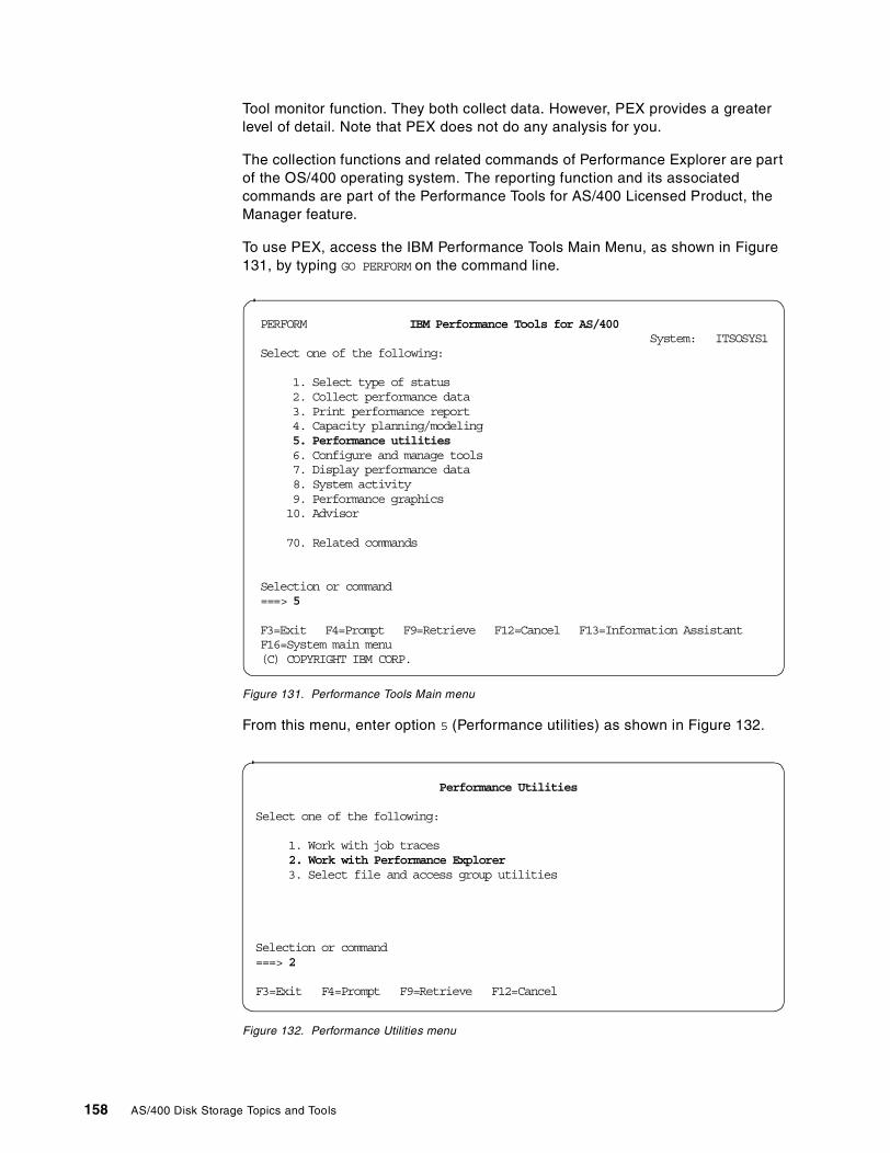
Tool monitor function. They both collect data. However, PEX provides a greaterlevel of detail. Note that PEX does not do any analysis for you.
The collection functions and related commands of Performance Explorer are partof the OS/400 operating system. The reporting function and its associatedcommands are part of the Performance Tools for AS/400 Licensed Product, theManager feature.
To use PEX, access the IBM Performance Tools Main Menu, as shown in Figure131, by typing GO PERFORM on the command line.
Figure 131. Performance Tools Main menu
From this menu, enter option 5 (Performance utilities) as shown in Figure 132.
Figure 132. Performance Utilities menu
PERFORM IBM Performance Tools for AS/400System: xxITSOSYS1
Select one of the following:
1. Select type of status2. Collect performance data3. Print performance report4. Capacity planning/modeling5. Performance utilities6. Configure and manage tools7. Display performance data8. System activity9. Performance graphics10. Advisor
70. Related commands
Selection or command===> 5
F3=Exit F4=Prompt F9=Retrieve F12=Cancel F13=Information AssistantF16=System main menu(C) COPYRIGHT IBM CORP.
Performance Utilities
Select one of the following:
1. Work with job traces2. Work with Performance Explorer3. Select file and access group utilities
Selection or command===> 2
F3=Exit F4=Prompt F9=Retrieve F12=Cancel
158 AS/400 Disk Storage Topics and Tools
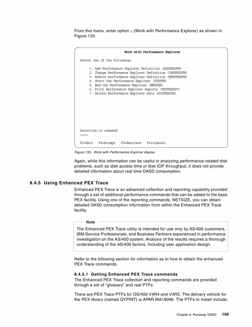
From this menu, enter option 2 (Work with Performance Explorer) as shown inFigure 133.
Figure 133. Work with Performance Explorer display
Again, while this information can be useful in analyzing performance-related diskproblems, such as disk access time or disk IOP throughput, it does not providedetailed information about real time DASD consumption.
8.4.5 Using Enhanced PEX TraceEnhanced PEX Trace is an advanced collection and reporting capability providedthrough a set of additional performance commands that can be added to the basePEX facility. Using one of the reporting commands, NETSIZE, you can obtaindetailed DASD consumption information from within the Enhanced PEX Tracefacility.
Refer to the following section for information as to how to obtain the enhancedPEX Trace commands.
8.4.5.1 Getting Enhanced PEX Trace commandsThe Enhanced PEX Trace collection and reporting commands are providedthrough a set of “glossary” and real PTFs.
There are PEX Trace PTFs for OS/400 V4R4 and V4R3. The delivery vehicle forthe PEX library (named QYPINT) is APAR MA19096. The PTFs to install include:
xxxxxxxxxxxxxxxxxxxxxxxxWork with Performance Explorer
Select one of the following:
1. Add Performance Explorer Definition (ADDPEXDFN)2. Change Performance Explorer Definition (CHGPEXDFN)3. Remove Performance Explorer Definition (RMVPEXDFN)4. Start the Performance Explorer (STRPEX)5. End the Performance Explorer (ENDPEX)6. Print Performance Explorer Reports (PRTPEXRPT)7. Delete Performance Explorer Data (DLTPEXDTA)
Selection or command===>
F3=Exit F4=Prompt F9=Retrieve F12=Cancel
The Enhanced PEX Trace utility is intended for use only by AS/400 customers,IBM Service Professionals, and Business Partners experienced in performanceinvestigation on the AS/400 system. Analysis of the results requires a thoroughunderstanding of the AS/400 factors, including user application design.
Note
Chapter 8. Runaway DASD 159
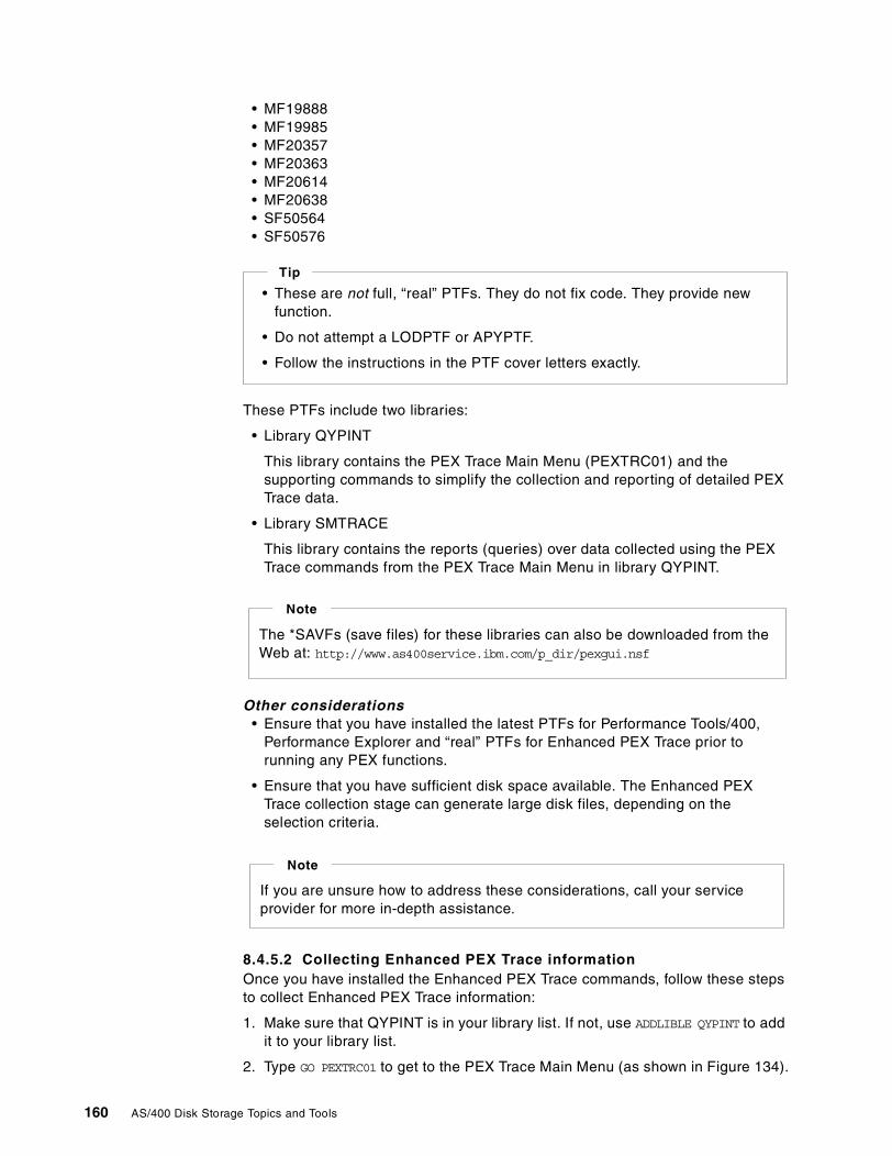
• MF19888• MF19985• MF20357• MF20363• MF20614• MF20638• SF50564• SF50576
These PTFs include two libraries:
• Library QYPINT
This library contains the PEX Trace Main Menu (PEXTRC01) and thesupporting commands to simplify the collection and reporting of detailed PEXTrace data.
• Library SMTRACE
This library contains the reports (queries) over data collected using the PEXTrace commands from the PEX Trace Main Menu in library QYPINT.
Other considerations• Ensure that you have installed the latest PTFs for Performance Tools/400,
Performance Explorer and “real” PTFs for Enhanced PEX Trace prior torunning any PEX functions.
• Ensure that you have sufficient disk space available. The Enhanced PEXTrace collection stage can generate large disk files, depending on theselection criteria.
8.4.5.2 Collecting Enhanced PEX Trace informationOnce you have installed the Enhanced PEX Trace commands, follow these stepsto collect Enhanced PEX Trace information:
1. Make sure that QYPINT is in your library list. If not, use ADDLIBLE QYPINT to addit to your library list.
2. Type GO PEXTRC01 to get to the PEX Trace Main Menu (as shown in Figure 134).
• These are not full, “real” PTFs. They do not fix code. They provide newfunction.
• Do not attempt a LODPTF or APYPTF.
• Follow the instructions in the PTF cover letters exactly.
Tip
The *SAVFs (save files) for these libraries can also be downloaded from theWeb at: http://www.as400service.ibm.com/p_dir/pexgui.nsf
Note
If you are unsure how to address these considerations, call your serviceprovider for more in-depth assistance.
Note
160 AS/400 Disk Storage Topics and Tools
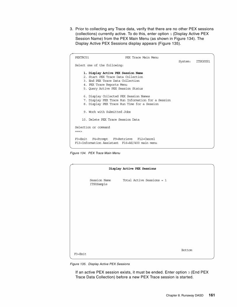
3. Prior to collecting any Trace data, verify that there are no other PEX sessions(collections) currently active. To do this, enter option 1 (Display Active PEXSession Name) from the PEX Main Menu (as shown in Figure 134). TheDisplay Active PEX Sessions display appears (Figure 135).
Figure 134. PEX Trace Main Menu
Figure 135. Display Active PEX Sessions
If an active PEX session exists, it must be ended. Enter option 3 (End PEXTrace Data Collection) before a new PEX Trace session is started.
PEXTRC01 PEX Trace Main MenuSystem: ITSOSYS1
Select one of the following:
1. Display Active PEX Session Name2. Start PEX Trace Data Collection3. End PEX Trace Data Collection4. PEX Trace Reports Menu5. Query Active PEX Session Status
6. Display Collected PEX Session Names7. Display PEX Trace Run Information for a Session8. Display PEX Trace Run Time for a Session
9. Work with Submitted Jobs
10. Delete PEX Trace Session Data
Selection or command===>
F3=Exit F4=Prompt F9=Retrieve F12=CancelF13=Information Assistant F16=AS/400 main menu
Display Active PEX Sessions
Session Name Total Active Sessions = 1ITSOSample
BottomF3=Exit
Chapter 8. Runaway DASD 161
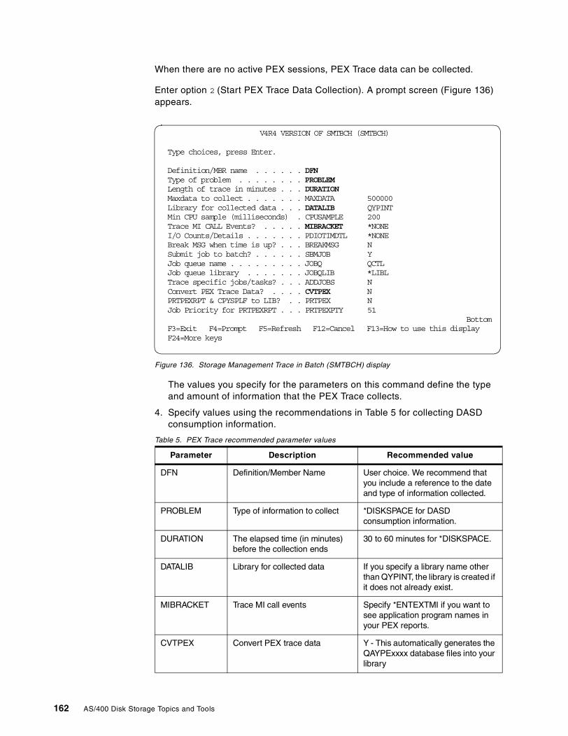
When there are no active PEX sessions, PEX Trace data can be collected.
Enter option 2 (Start PEX Trace Data Collection). A prompt screen (Figure 136)appears.
Figure 136. Storage Management Trace in Batch (SMTBCH) display
The values you specify for the parameters on this command define the typeand amount of information that the PEX Trace collects.
4. Specify values using the recommendations in Table 5 for collecting DASDconsumption information.
Table 5. PEX Trace recommended parameter values
Parameter Description Recommended value
DFN Definition/Member Name User choice. We recommend thatyou include a reference to the dateand type of information collected.
PROBLEM Type of information to collect *DISKSPACE for DASDconsumption information.
DURATION The elapsed time (in minutes)before the collection ends
30 to 60 minutes for *DISKSPACE.
DATALIB Library for collected data If you specify a library name otherthan QYPINT, the library is created ifit does not already exist.
MIBRACKET Trace MI call events Specify *ENTEXTMI if you want tosee application program names inyour PEX reports.
CVTPEX Convert PEX trace data Y - This automatically generates theQAYPExxxx database files into yourlibrary
V4R4 VERSION OF SMTBCH (SMTBCH)
Type choices, press Enter.
Definition/MBR name . . . . . . DFNType of problem . . . . . . . . PROBLEMLength of trace in minutes . . . DURATIONMaxdata to collect . . . . . . . MAXDATA 500000Library for collected data . . . DATALIB QYPINTMin CPU sample (milliseconds) . CPUSAMPLE 200Trace MI CALL Events? . . . . . MIBRACKET *NONEI/O Counts/Details . . . . . . . PDIOTIMDTL *NONEBreak MSG when time is up? . . . BREAKMSG NSubmit job to batch? . . . . . . SBMJOB YJob queue name . . . . . . . . . JOBQ QCTLJob queue library . . . . . . . JOBQLIB *LIBLTrace specific jobs/tasks? . . . ADDJOBS NConvert PEX Trace Data? . . . . CVTPEX NPRTPEXRPT & CPYSPLF to LIB? . . PRTPEX NJob Priority for PRTPEXRPT . . . PRTPEXPTY 51
BottomF3=Exit F4=Prompt F5=Refresh F12=Cancel F13=How to use this displayF24=More keys
162 AS/400 Disk Storage Topics and Tools
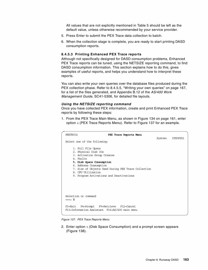
All values that are not explicitly mentioned in Table 5 should be left as thedefault value, unless otherwise recommended by your service provider.
5. Press Enter to submit the PEX Trace data collection to batch.
6. When the collection stage is complete, you are ready to start printing DASDconsumption reports.
8.4.5.3 Printing Enhanced PEX Trace reportsAlthough not specifically designed for DASD consumption problems, EnhancedPEX Trace reports can be tuned, using the NETSIZE reporting command, to findDASD consumption information. This section explains how to do this, givesexamples of useful reports, and helps you understand how to interpret thesereports.
You can also write your own queries over the database files produced during thePEX collection phase. Refer to 8.4.5.5, “Writing your own queries” on page 167,for a list of the files generated, and Appendix B.12 of the AS/400 WorkManagement Guide, SC41-5306, for detailed file layouts.
Using the NETSIZE reporting commandOnce you have collected PEX information, create and print Enhanced PEX Tracereports by following these steps:
1. From the PEX Trace Main Menu, as shown in Figure 134 on page 161, enteroption 4 (PEX Trace Reports Menu). Refer to Figure 137 for an example.
Figure 137. PEX Trace Reports Menu
2. Enter option 5 (Disk Space Consumption) and a prompt screen appears(Figure 138).
PEXTRC02 PEX Trace Reports MenuSystem: ITSOSYS1
Select one of the following:
1. Full File Opens2. Physical Disk IOs3. Activation Group Creates4. Faults5. Disk Space Consumption6. Address Consumption7. Size of Objects Used During PEX Trace Collection8. CPU Utilization9. Program Activations and Deactivations
Selection or command===> 5
F3=Exit F4=Prompt F9=Retrieve F12=CancelF13=Information Assistant F16=AS/400 main menu
Chapter 8. Runaway DASD 163
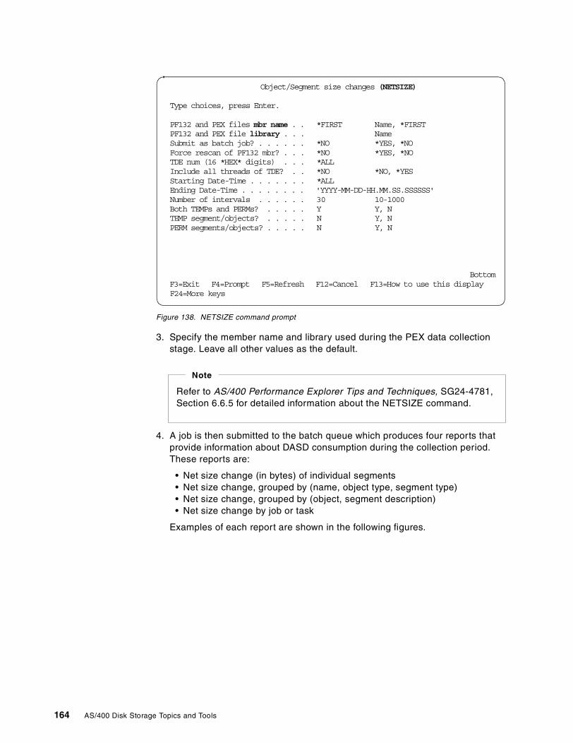
Figure 138. NETSIZE command prompt
3. Specify the member name and library used during the PEX data collectionstage. Leave all other values as the default.
4. A job is then submitted to the batch queue which produces four reports thatprovide information about DASD consumption during the collection period.These reports are:
• Net size change (in bytes) of individual segments• Net size change, grouped by (name, object type, segment type)• Net size change, grouped by (object, segment description)• Net size change by job or task
Examples of each report are shown in the following figures.
Object/Segment size changes (NETSIZE)
Type choices, press Enter.
PF132 and PEX files mbr name . . *FIRST Name, *FIRSTPF132 and PEX file library . . . NameSubmit as batch job? . . . . . . *NO *YES, *NOForce rescan of PF132 mbr? . . . *NO *YES, *NOTDE num (16 *HEX* digits) . . . *ALLInclude all threads of TDE? . . *NO *NO, *YESStarting Date-Time . . . . . . . *ALLEnding Date-Time . . . . . . . . 'YYYY-MM-DD-HH.MM.SS.SSSSSS'Number of intervals . . . . . . 30 10-1000Both TEMPs and PERMs? . . . . . Y Y, NTEMP segment/objects? . . . . . N Y, NPERM segments/objects? . . . . . N Y, N
BottomF3=Exit F4=Prompt F5=Refresh F12=Cancel F13=How to use this displayF24=More keys
Refer to AS/400 Performance Explorer Tips and Techniques, SG24-4781,Section 6.6.5 for detailed information about the NETSIZE command.
Note
164 AS/400 Disk Storage Topics and Tools
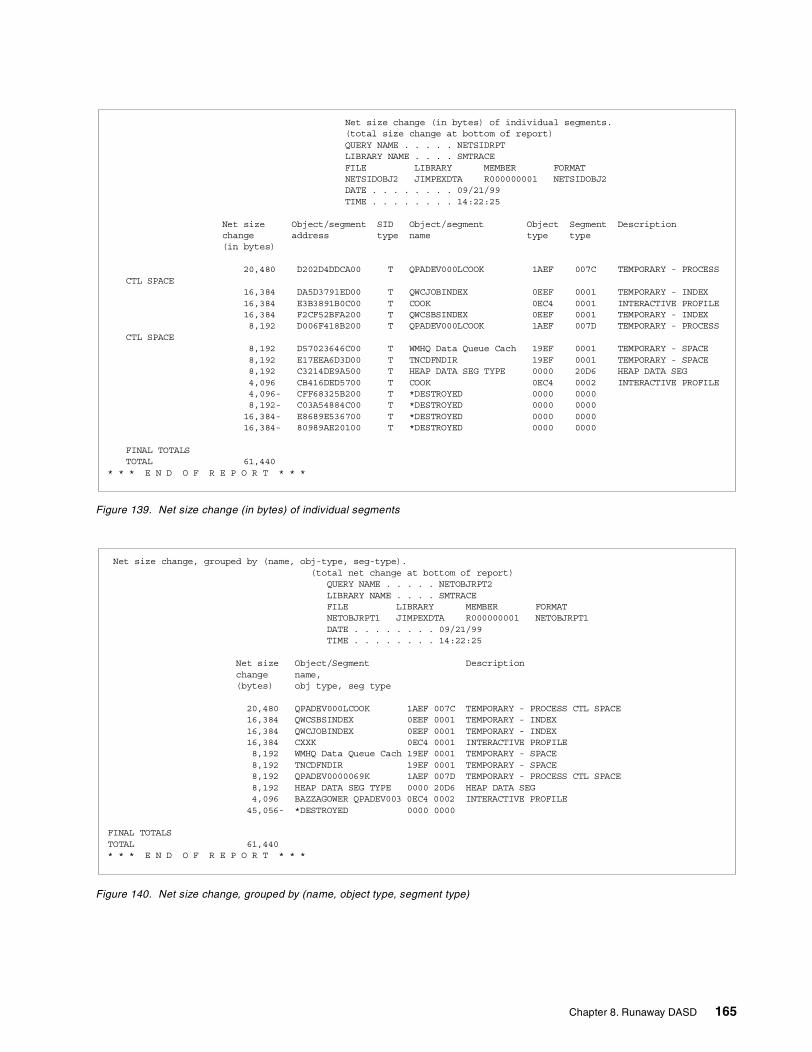
Figure 139. Net size change (in bytes) of individual segments
Figure 140. Net size change, grouped by (name, object type, segment type)
Net size change (in bytes) of individual segments.(total size change at bottom of report)QUERY NAME . . . . . NETSIDRPTLIBRARY NAME . . . . SMTRACEFILE LIBRARY MEMBER FORMATNETSIDOBJ2 JIMPEXDTA R000000001 NETSIDOBJ2DATE . . . . . . . . 09/21/99TIME . . . . . . . . 14:22:25
Net size Object/segment SID Object/segment Object Segment Descriptionchange address type name type type(in bytes)
20,480 D202D4DDCA00 T QPADEV000LCOOK 1AEF 007C TEMPORARY - PROCESSCTL SPACE
16,384 DA5D3791ED00 T QWCJOBINDEX 0EEF 0001 TEMPORARY - INDEX16,384 E3B3891B0C00 T COOK 0EC4 0001 INTERACTIVE PROFILE16,384 F2CF52BFA200 T QWCSBSINDEX 0EEF 0001 TEMPORARY - INDEX8,192 D006F418B200 T QPADEV000LCOOK 1AEF 007D TEMPORARY - PROCESS
CTL SPACE8,192 D57023646C00 T WMHQ Data Queue Cach 19EF 0001 TEMPORARY - SPACE8,192 E17EEA6D3D00 T TNCDFNDIR 19EF 0001 TEMPORARY - SPACE8,192 C3214DE9A500 T HEAP DATA SEG TYPE 0000 20D6 HEAP DATA SEG4,096 CB416DED5700 T COOK 0EC4 0002 INTERACTIVE PROFILE4,096- CFF68325B200 T *DESTROYED 0000 00008,192- C03A54884C00 T *DESTROYED 0000 000016,384- E8689E536700 T *DESTROYED 0000 000016,384- 80989AE20100 T *DESTROYED 0000 0000
FINAL TOTALSTOTAL 61,440
* * * E N D O F R E P O R T * * *
Net size change, grouped by (name, obj-type, seg-type).(total net change at bottom of report)
QUERY NAME . . . . . NETOBJRPT2LIBRARY NAME . . . . SMTRACEFILE LIBRARY MEMBER FORMATNETOBJRPT1 JIMPEXDTA R000000001 NETOBJRPT1DATE . . . . . . . . 09/21/99TIME . . . . . . . . 14:22:25
Net size Object/Segment Descriptionchange name,(bytes) obj type, seg type
20,480 QPADEV000LCOOK 1AEF 007C TEMPORARY - PROCESS CTL SPACE16,384 QWCSBSINDEX 0EEF 0001 TEMPORARY - INDEX16,384 QWCJOBINDEX 0EEF 0001 TEMPORARY - INDEX16,384 CXXK 0EC4 0001 INTERACTIVE PROFILE8,192 WMHQ Data Queue Cach 19EF 0001 TEMPORARY - SPACE8,192 TNCDFNDIR 19EF 0001 TEMPORARY - SPACE8,192 QPADEV0000069K 1AEF 007D TEMPORARY - PROCESS CTL SPACE8,192 HEAP DATA SEG TYPE 0000 20D6 HEAP DATA SEG4,096 BAZZAGOWER QPADEV003 0EC4 0002 INTERACTIVE PROFILE45,056- *DESTROYED 0000 0000
FINAL TOTALSTOTAL 61,440* * * E N D O F R E P O R T * * *
Chapter 8. Runaway DASD 165
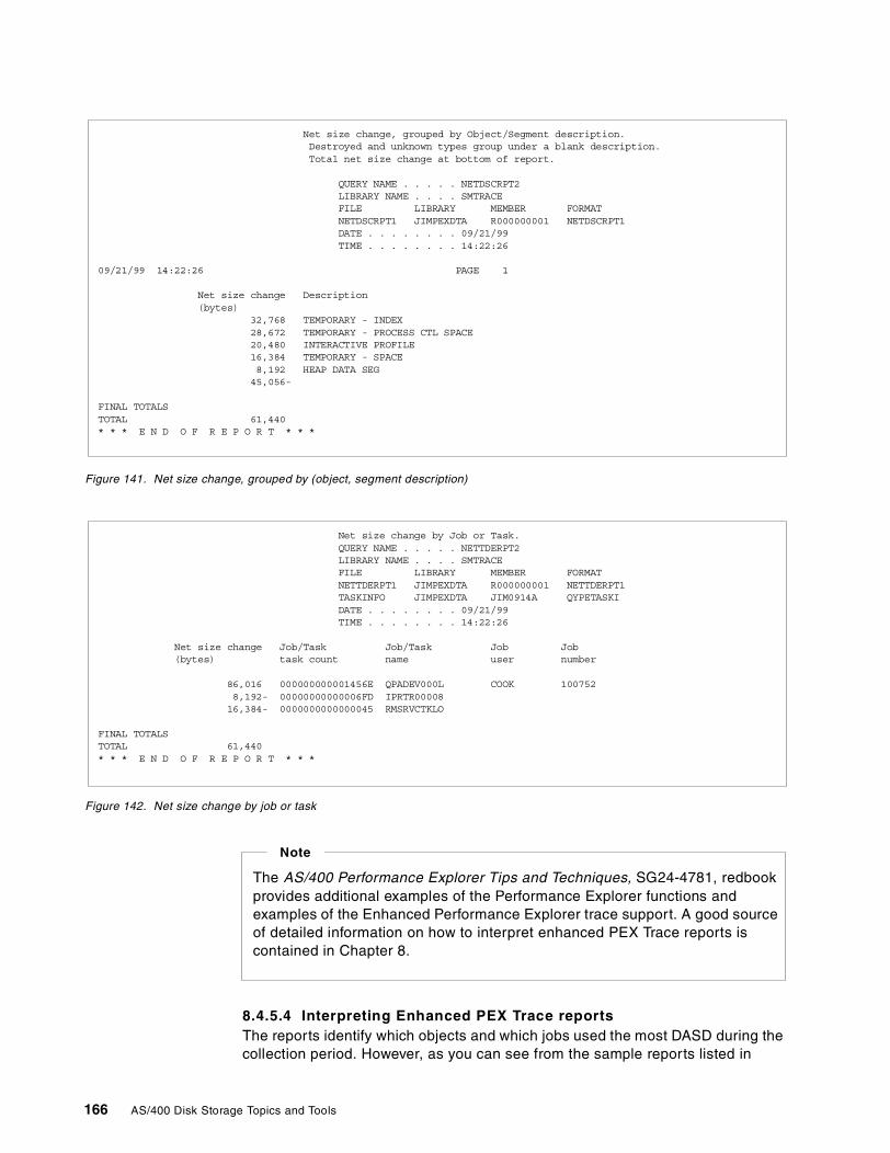
Figure 141. Net size change, grouped by (object, segment description)
Figure 142. Net size change by job or task
8.4.5.4 Interpreting Enhanced PEX Trace reportsThe reports identify which objects and which jobs used the most DASD during thecollection period. However, as you can see from the sample reports listed in
Net size change, grouped by Object/Segment description.Destroyed and unknown types group under a blank description.Total net size change at bottom of report.
QUERY NAME . . . . . NETDSCRPT2LIBRARY NAME . . . . SMTRACEFILE LIBRARY MEMBER FORMATNETDSCRPT1 JIMPEXDTA R000000001 NETDSCRPT1DATE . . . . . . . . 09/21/99TIME . . . . . . . . 14:22:26
09/21/99 14:22:26 PAGE 1
Net size change Description(bytes)
32,768 TEMPORARY - INDEX28,672 TEMPORARY - PROCESS CTL SPACE20,480 INTERACTIVE PROFILE16,384 TEMPORARY - SPACE8,192 HEAP DATA SEG45,056-
FINAL TOTALSTOTAL 61,440* * * E N D O F R E P O R T * * *
Net size change by Job or Task.QUERY NAME . . . . . NETTDERPT2LIBRARY NAME . . . . SMTRACEFILE LIBRARY MEMBER FORMATNETTDERPT1 JIMPEXDTA R000000001 NETTDERPT1TASKINFO JIMPEXDTA JIM0914A QYPETASKIDATE . . . . . . . . 09/21/99TIME . . . . . . . . 14:22:26
Net size change Job/Task Job/Task Job Job(bytes) task count name user number
86,016 000000000001456E QPADEV000L COOK 1007528,192- 00000000000006FD IPRTR0000816,384- 0000000000000045 RMSRVCTKLO
FINAL TOTALSTOTAL 61,440* * * E N D O F R E P O R T * * *
The AS/400 Performance Explorer Tips and Techniques, SG24-4781, redbookprovides additional examples of the Performance Explorer functions andexamples of the Enhanced Performance Explorer trace support. A good sourceof detailed information on how to interpret enhanced PEX Trace reports iscontained in Chapter 8.
Note
166 AS/400 Disk Storage Topics and Tools
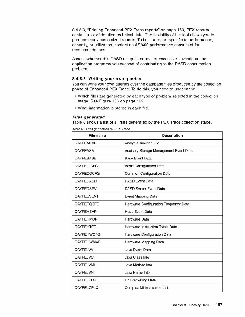
8.4.5.3, “Printing Enhanced PEX Trace reports” on page 163, PEX reportscontain a lot of detailed technical data. The flexibility of the tool allows you toproduce many customized reports. To build a report specific to performance,capacity, or utilization, contact an AS/400 performance consultant forrecommendations.
Assess whether this DASD usage is normal or excessive. Investigate theapplication programs you suspect of contributing to the DASD consumptionproblem.
8.4.5.5 Writing your own queriesYou can write your own queries over the database files produced by the collectionphase of Enhanced PEX Trace. To do this, you need to understand:
• Which files are generated by each type of problem selected in the collectionstage. See Figure 136 on page 162.
• What information is stored in each file.
Files generatedTable 6 shows a list of all files generated by the PEX Trace collection stage.
Table 6. Files generated by PEX Trace
File name Description
QAYPEANAL Analysis Tracking File
QAYPEASM Auxiliary Storage Management Event Data
QAYPEBASE Base Event Data
QAYPECICFG Basic Configuration Data
QAYPECOCFG Common Configuration Data
QAYPEDASD DASD Event Data
QAYPEDSRV DASD Server Event Data
QAYPEEVENT Event Mapping Data
QAYPEFQCFG Hardware Configuration Frequency Data
QAYPEHEAP Heap Event Data
QAYPEHMON Hardware Data
QAYPEHTOT Hardware Instruction Totals Data
QAYPEHWCFG Hardware Configuration Data
QAYPEHWMAP Hardware Mapping Data
QAYPEJVA Java Event Data
QAYPEJVCI Java Class Info
QAYPEJVMI Java Method Info
QAYPEJVNI Java Name Info
QAYPELBRKT Lic Bracketing Data
QAYPELCPLX Complex MI Instruction List
Chapter 8. Runaway DASD 167
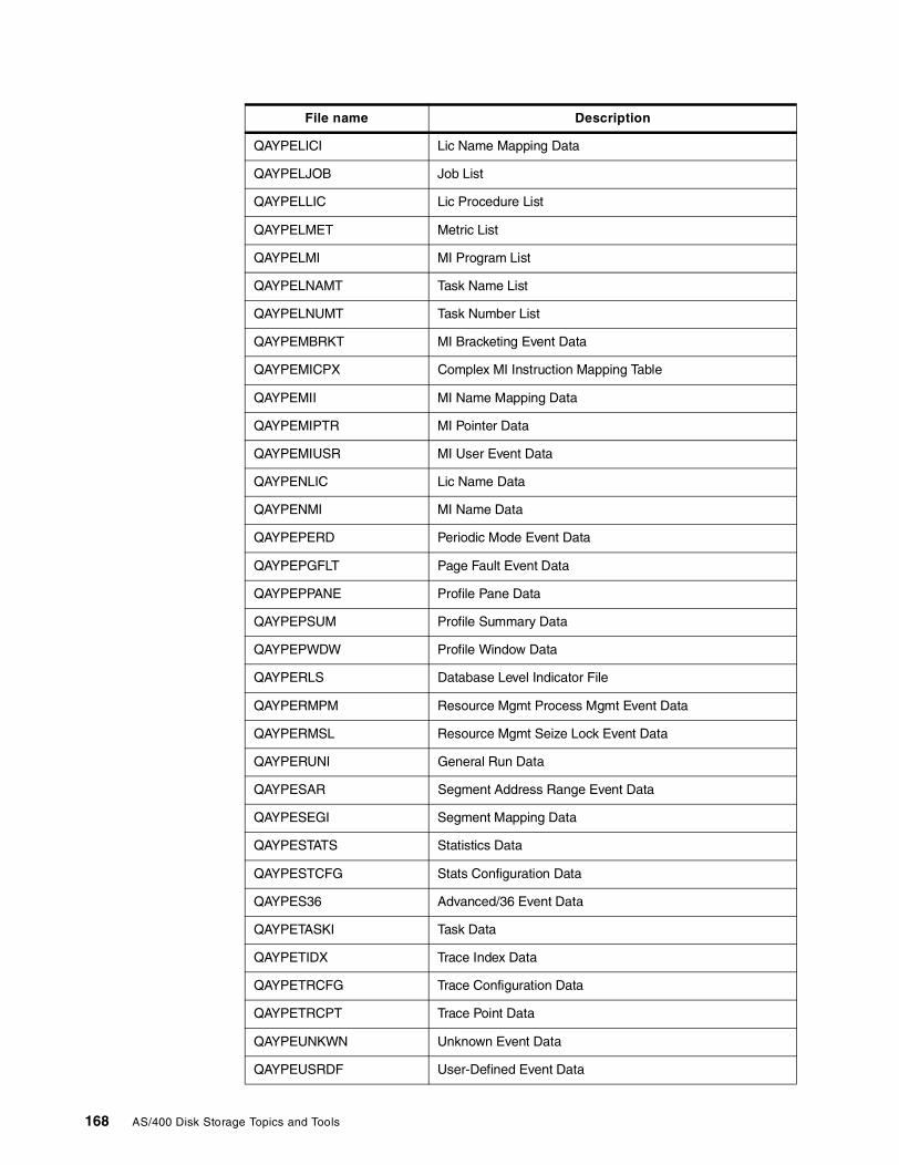
QAYPELICI Lic Name Mapping Data
QAYPELJOB Job List
QAYPELLIC Lic Procedure List
QAYPELMET Metric List
QAYPELMI MI Program List
QAYPELNAMT Task Name List
QAYPELNUMT Task Number List
QAYPEMBRKT MI Bracketing Event Data
QAYPEMICPX Complex MI Instruction Mapping Table
QAYPEMII MI Name Mapping Data
QAYPEMIPTR MI Pointer Data
QAYPEMIUSR MI User Event Data
QAYPENLIC Lic Name Data
QAYPENMI MI Name Data
QAYPEPERD Periodic Mode Event Data
QAYPEPGFLT Page Fault Event Data
QAYPEPPANE Profile Pane Data
QAYPEPSUM Profile Summary Data
QAYPEPWDW Profile Window Data
QAYPERLS Database Level Indicator File
QAYPERMPM Resource Mgmt Process Mgmt Event Data
QAYPERMSL Resource Mgmt Seize Lock Event Data
QAYPERUNI General Run Data
QAYPESAR Segment Address Range Event Data
QAYPESEGI Segment Mapping Data
QAYPESTATS Statistics Data
QAYPESTCFG Stats Configuration Data
QAYPES36 Advanced/36 Event Data
QAYPETASKI Task Data
QAYPETIDX Trace Index Data
QAYPETRCFG Trace Configuration Data
QAYPETRCPT Trace Point Data
QAYPEUNKWN Unknown Event Data
QAYPEUSRDF User-Defined Event Data
File name Description
168 AS/400 Disk Storage Topics and Tools
Data file layoutsA complete list of PEX Trace file layouts is contained in Appendix B.12 of theAS/400 Work Management Guide, SC41-5306.
8.5 Summary
As previously mentioned, the information described in this chapter is based onVersion 4 Release 4 of OS/400. It is by no means exhaustive. The IBM toolsdescribed in this chapter may be enhanced, or new ones provided, in futurereleases of the operating system. Further information and assistance inidentifying and addressing DASD consumption problems may be available fromyour local service provider.
Chapter 8. Runaway DASD 169

170 AS/400 Disk Storage Topics and Tools
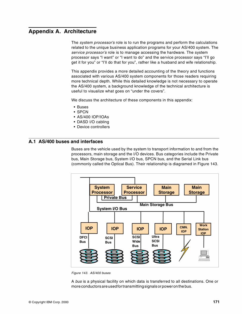
Appendix A. Architecture
The system processor’s role is to run the programs and perform the calculationsrelated to the unique business application programs for your AS/400 system. Theservice processor’s role is to manage accessing the hardware. The systemprocessor says “I want” or “I want to do” and the service processor says “I’ll goget it for you” or “I’ll do that for you”, rather like a husband and wife relationship.
This appendix provides a more detailed accounting of the theory and functionsassociated with various AS/400 system components for those readers requiringmore technical depth. While this detailed knowledge is not necessary to operatethe AS/400 system, a background knowledge of the technical architecture isuseful to visualize what goes on “under the covers”.
We discuss the architecture of these components in this appendix:
• Buses• SPCN• AS/400 IOP/IOAs• DASD I/O cabling• Device controllers
A.1 AS/400 buses and interfaces
Buses are the vehicle used by the system to transport information to and from theprocessors, main storage and the I/O devices. Bus categories include the Privatebus, Main Storage bus, System I/O bus, SPCN bus, and the Serial Link bus(commonly called the Optical Bus). Their relationship is diagramed in Figure 143.
Figure 143. AS/400 buses
A bus is a physical facility on which data is transferred to all destinations. One ormore conductorsareusedfor transmittingsignalsorpoweron the bus.
SystemProcessor
ServiceProcessor
MainStorage
MainStorage
IOP IOP IOP IOP CMN.IOP
WorkStation
IOP
Private Bus
Main Storage BusSystem I/O Bus
DFCIBus
SCSIBus
SCSIWideBus
UltraSCSIBus
© Copyright IBM Corp. 2000 171
Buses used on the AS/400 system include:
• Private bus• Main storage bus• I/O (system I/O) bus: Both SPD and PCI architecture• IOP to device bus
– SPD: Both DFCI and SCSI standards– PCI: SCSI standard
• System Power Control Network bus (SPCN)
Interfaces are the cabling that connect the IOP and IOAs to the devicecontrollers. The controller passes information to the I/O devices as a permanentrecord, in the form of printed, displayed, or written information.
Interface types include the Device Function Controller Interface (DFCI) and theSmall Computer System Interface (SCSI). Three variations are referenced inFigure 143 on page 171.
A.1.1 Private and main storage buses
This section introduces the function of the private and main storage buses. Referto Chapter 1, “System architecture” on page 3, for more detailed informationabout both the system and service processors.
Private and main storage buses are internal buses. The private bus consists ofcontrol lines between the service processor and the system processor. Theprivate bus carries programs, instructions, commands, and information betweenthe system processor and the service processor. Control lines built into theprivate bus switch control between the processors.
The private bus is necessary because the system processor has no read onlystorage (ROS) and cannot give bus control function until loaded with LicensedInternal Code during an IPL. The service processor controls the bus to access itsown code and the system processor code from the load source I/O bus unit. Theservice processor diagnostic support uses the private bus to obtain control of theI/O bus when errors occur in the system processor.
The main storage bus carries information such as programs, instructions, anddata between the main storage cards, the system and service processors, andthe I/O bus control units (BCU). In AS/400 systems, BCUs are located within thesystem processor and the service processor, as well as within the bus adaptercards.
A.1.2 I/O bus (system I/O buses)
An I/O bus (also known as a data bus) is used to communicate data internally andexternally to and from a processing unit, storage, and peripheral devices. Itprovides all signal, power, and ground connections to the internal adapters (IOPsand IOAs).
There are two architectures of I/O buses:
• System Products Division (SPD)• Peripheral Component Interconnect (PCI)
The SPD bus is named after the division which developed it. It is used acrossmultiple platforms. SPD has been the state of the art technology for decades.
172 AS/400 Disk Storage Topics and Tools
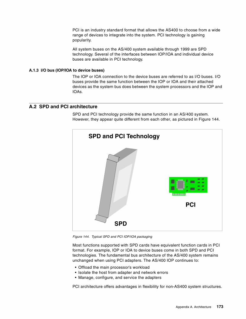
PCI is an industry standard format that allows the AS400 to choose from a widerange of devices to integrate into the system. PCI technology is gainingpopularity.
All system buses on the AS/400 system available through 1999 are SPDtechnology. Several of the interfaces between IOP/IOA and individual devicebuses are available in PCI technology.
A.1.3 I/O bus (IOP/IOA to device buses)
The IOP or IOA connection to the device buses are referred to as I/O buses. I/Obuses provide the same function between the IOP or IOA and their attacheddevices as the system bus does between the system processors and the IOP andIOAs.
A.2 SPD and PCI architecture
SPD and PCI technology provide the same function in an AS/400 system.However, they appear quite different from each other, as pictured in Figure 144.
Figure 144. Typical SPD and PCI IOP/IOA packaging
Most functions supported with SPD cards have equivalent function cards in PCIformat. For example, IOP or IOA to device buses come in both SPD and PCItechnologies. The fundamental bus architecture of the AS/400 system remainsunchanged when using PCI adapters. The AS/400 IOP continues to:
• Offload the main processor’s workload• Isolate the host from adapter and network errors• Manage, configure, and service the adapters
PCI architecture offers advantages in flexibility for non-AS400 system structures.
SPD and PCI Technology
PCI
SPD
Appendix A. Architecture 173
Some products are designated Customer Setup (CSU). Customer InstallableFeatures (CIF) was introduced on the Model 600, 170 and 150 for orders ofadditional features, such as disk features, PCI I/O cards, and external cables.PCI cards enable an implementation of CIF.
SPD and PCI buses are further distinguished with different technologies, asdiscussed in A.2.1, “Device Function Controller Interface (DFCI) bus” on page174, and A.2.2, “Small Computer System Interface (SCSI) bus” on page 174.
Whether SPD or PCI is available depends on the system model. Early models, inparticular, only have SPD technology. Many models, manufactured beginning withOS/400 V4R1, may have only SPD, or may have a mix of SPD and PCI, or mayhave all PCI components. The system model number referenced determineswhich technology is available.
The number of processors are too numerous to mention in this redbook. For alisting of current SPD and PCI processor choices, refer to the AS/400 SystemBuilder, SG24-2155, or the AS/400e System Handbook, GA19-5486.
A.2.1 Device Function Controller Interface (DFCI) bus
The DFCI bus uses a protocol to communicate with the IOPs. In earliergenerations of computing architecture, this was the preferred industry standard.
The DFCI bus is the IBM implementation of the ANSI IPI-3 industry standards. InIPI-3, the system processor stays linked to the IOP/IOA until whatever theprocess the IOP/ IOA is to perform completes. Any device on the IOP/IOAcommunicates with any other device on the same IOP/IOA through the systemprocessor. The device controllers in this architecture depend on the IOP andsystem processor to function.
Device types that utilize the DFCI interface on the AS/400 system include:
• 9331 Diskette Unit• 9332 Disk Unit• 9335 Disk Controller Unit - Model A01• 9335 Disk Storage Unit - Model B01• 9336 Disk Unit• 9347 Tape Unit
These device types are explained in A.2.2, “Small Computer System Interface(SCSI) bus” on page 174.
A.2.2 Small Computer System Interface (SCSI) bus
As device interface technology improves, there is less utilization of devicesrequiring DFCI. Small computer system interface (SCSI) interface provides thesame function, but more flexibility.
The SCSI bus is designed to support an any-to-any communications protocol withdevice-to-device transfer permitted between devices within the same device unit.The use of SCSI enables advances such as RAID-5 and integrated hardware diskcompression within a device subsystem.
An advantages of the SCSI bus over the DCFI bus is that the device controllerscan work independently from the IOP/IOA and the system processor. Thus, the
174 AS/400 Disk Storage Topics and Tools
system processor issues a command to the device and disconnects from thedevice before the device completes the requested function. This frees the systemprocessor and the IOP/IOA to go on with other tasks, while the device completesthe requested function. This improved speed increases the amount of systemthroughput.
A.2.2.1 SCSI options on the AS/400 systemSCSI architecture is implemented in several forms on the AS/400: SCSI wide,SCSI1 and SCSI2.
Low-end AS/400 models use SCSI to connect to tape and disk devices. Mid- andhigh-end AS/400 models connect these SCSI device types:
• 2440 tape unit• 2800 and 2801 integrated disk units• 2802 integrated disk units (SCSI wide)• 636x tape unit• 7208 tape unit• 9346 tape unit• 9348 tape unit• 9337 disk unit models (0XX and 1XX use SCSI)• 9337 disk unit models (2XX, 4XX, and 5XX use SCSI wide)• All internal disk unit models
SCSI wide busThe SCSI wide bus is the same architecture as the SCSI bus, except the SCSIwide bus has a wider bandwidth on which to transfer data.
SCSI wide is used on the 9337 model 2XX, 4XX, 5XX, and storage units of someAdvance Series and eSeries system models.
SCSI 1 and SCSI 2The different types of SCSI (SCSI-1 and SCSI-2) refer to the driver and receiverused.
The number 2 in SCSI-2 implies that it is the second version of SCSI standards.SCSI-2 supports SCSI-1 since it consists of the SCSI 1 basics.
All interfaces on the internal and external devices on Stage 1 processors (that is,the AS/400 Model B) use SCSI-1.
Beginning with Stage 2 systems (as in the AS/400 Model D, E, and F models),interfaces on the integrated (internal) devices supported by the baseMulti-Function IOP (MFIOP) are SCSI-2.
The SCSI-2 interface supports SCSI-1 devices, such as the #2800 and #2801disk unit devices. The #2802 is a SCSI-2 device running on the same MFIOP.Internal DASD installed in a #5051, #5052 or #5058, utilize the SCSI-2 interface(except repackaged #2800 and #2801 DASD).
The #5051 or #5052 and all storage expansions manufactured subsequently runon an IOP to provide a SCSI-2 interface. SCSI-1 devices are supported in the firstseven logical slots.
Appendix A. Architecture 175
External storage developed for the AS/400 system, beginning with the model 2XX9337s and continuing with the Enterprise Storage and Versatile Storage Servers,attach using SCSI-2 interfaces.
The following lists distinguish SCSI-1 from SCSI-2:
• SCSI-1 is single-ended. Characteristics include:
– Low cost.– Do not require twisted pair wire.– Maximum cable length of 19.605 feet.– Susceptible to electrical noise.– Used primarily for connections within a cabinet.– Termination is done at the end of each cable or on the device.– Distance between device and bus must be less than 3.921 inches.– Distance between device and device must be at least 13.070 inches.
• SCSI-2 has a differential end. Characteristics include:
– Higher cost.– Maximum cable length 81.688 feet. Twisted pair wire recommended.– Less susceptible to electrical noise than SCSI single-ended.– Primarily used for connections external to a cabinet.– Termination is done at the end of each cable or on the device.– Distance between device and bus must be less than 26.140 inches.– Distance between device and device must be at least 13.070 inches.
A.2.3 The system power control network (SPCN) bus
The system power control network (SPCN) bus carries data that controls andmonitors power between AS/400 racks, towers, and units.
Implementing a SPCN bus enables the system to receive and post SystemReference Codes (SRCs) and messages relating to power when traditional pathsare unavailable because of the loss of power. The SPCN bus enables the systemthrough relays to control the power to turn off or on individual components withinthe system.
In stage one hardware (before the creation of SPCN), the entire system ispowered off to service any one area of the system. If power is lost to any area,the entire system loses power.
176 AS/400 Disk Storage Topics and Tools
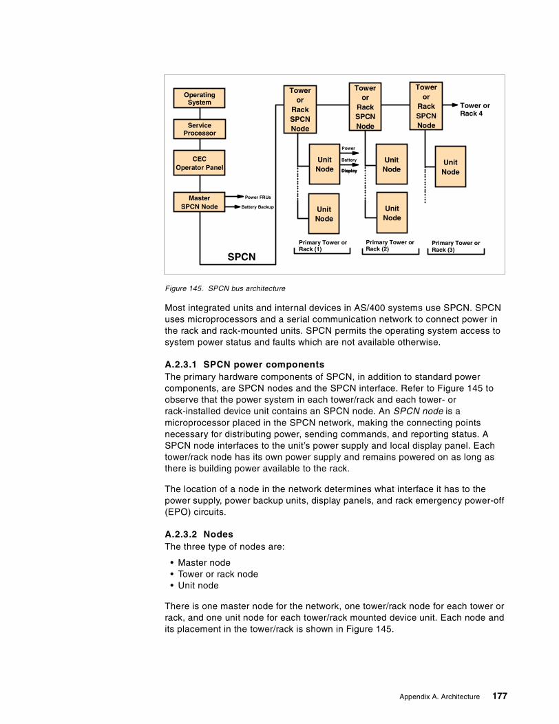
Figure 145. SPCN bus architecture
Most integrated units and internal devices in AS/400 systems use SPCN. SPCNuses microprocessors and a serial communication network to connect power inthe rack and rack-mounted units. SPCN permits the operating system access tosystem power status and faults which are not available otherwise.
A.2.3.1 SPCN power componentsThe primary hardware components of SPCN, in addition to standard powercomponents, are SPCN nodes and the SPCN interface. Refer to Figure 145 toobserve that the power system in each tower/rack and each tower- orrack-installed device unit contains an SPCN node. An SPCN node is amicroprocessor placed in the SPCN network, making the connecting pointsnecessary for distributing power, sending commands, and reporting status. ASPCN node interfaces to the unit’s power supply and local display panel. Eachtower/rack node has its own power supply and remains powered on as long asthere is building power available to the rack.
The location of a node in the network determines what interface it has to thepower supply, power backup units, display panels, and rack emergency power-off(EPO) circuits.
A.2.3.2 NodesThe three type of nodes are:
• Master node• Tower or rack node• Unit node
There is one master node for the network, one tower/rack node for each tower orrack, and one unit node for each tower/rack mounted device unit. Each node andits placement in the tower/rack is shown in Figure 145.
OperatingSystem
ServiceProcessor
CECOperator Panel
MasterSPCN Node
Power FRUs
Battery Backup
SPCN
Tower orRack 4
Display
Battery
Power
Display
UnitNode
UnitNode
Toweror
RackSPCNNode
Toweror
RackSPCNNode
Toweror
RackSPCNNode
UnitNode
UnitNode
UnitNode
Primary Tower orRack (1)
Primary Tower orRack (2)
Primary Tower orRack (3)
Appendix A. Architecture 177
Master nodeThe master node is the interface between the operating system and the serialnetwork. The master node is a microprocessor located in the primary systemtower or rack. The master node is programmed to issue network commands andpoll for status from other SPCN nodes in the network.
The master node communicates with the operating system (through the controlpanel), exchanging commands and network status. The master node monitorspower and status of the power supply. During power interruption the master nodestarts backup power. The master node is powered on as long as building power isavailable to the tower or rack.
Command responses and error status from the SPCN network are collected bythe master node and formatted for return to the operating system.
Tower or rack nodeA tower or rack SPCN node is located in each tower or rack. It receives power-onand power-off commands from the master node for switching AC power (on or off)to the tower- or rack-mounted units. Each tower or rack node controls powerswitching to outlets within racks, and to power connections within towers. Theoutlets are switched on or off in groups of five.
Unit nodeThe unit node is a microprocessor located inside an AS/400-attached device(with SPCN circuits). Each unit node is programmed to report device status andrespond to commands from the master node.
A.3 SPCN interfaces
The SPCN nodes in each unit are connected to rack ports with copper cables orthrough internal cabling, depending on the location of the unit, and to towernodes through internal cabling. The nodes in each tower or rack are seriallyconnected to other towers or racks with copper or optical cables.
In SPCN-enabled systems, bulk power modules, system regulators, batterybackup units, power components of internal DASD and tape, as well as othersystem power components can be monitored and controlled. If errors occur, thesystem operator message queue (QSYSOPR or sometimes QSYSMSG), also isnotified of the failing power condition. The message contains detailed informationabout the failure, often identifying a field replaceable unit (FRU) to be replaced.
The first external units to use the SPCN network were introduced with OS/400V2R3.
Beginning with the Advanced Series AS/400 models, the SCSI buses can bequiesced, using SPCN, for a few seconds. This allows a single storage unit to bephysically removed from the system and serviced in concurrent mode. This isaccomplished through a call command, as in CALL QCNCMNT.
Beginning with the update of OS/400 V3R7 (February 1997), this function is anoption from the Hardware Service Manager (HSM) menu screen. Beginning withOS/400 V4R1, this function is more efficiently incorporated under the control ofSLIC.
178 AS/400 Disk Storage Topics and Tools
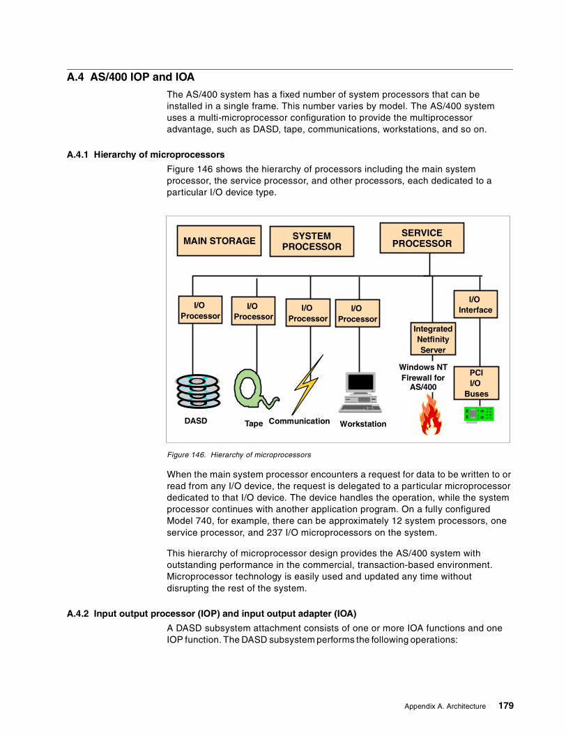
A.4 AS/400 IOP and IOA
The AS/400 system has a fixed number of system processors that can beinstalled in a single frame. This number varies by model. The AS/400 systemuses a multi-microprocessor configuration to provide the multiprocessoradvantage, such as DASD, tape, communications, workstations, and so on.
A.4.1 Hierarchy of microprocessors
Figure 146 shows the hierarchy of processors including the main systemprocessor, the service processor, and other processors, each dedicated to aparticular I/O device type.
Figure 146. Hierarchy of microprocessors
When the main system processor encounters a request for data to be written to orread from any I/O device, the request is delegated to a particular microprocessordedicated to that I/O device. The device handles the operation, while the systemprocessor continues with another application program. On a fully configuredModel 740, for example, there can be approximately 12 system processors, oneservice processor, and 237 I/O microprocessors on the system.
This hierarchy of microprocessor design provides the AS/400 system withoutstanding performance in the commercial, transaction-based environment.Microprocessor technology is easily used and updated any time withoutdisrupting the rest of the system.
A.4.2 Input output processor (IOP) and input output adapter (IOA)
A DASD subsystem attachment consists of one or more IOA functions and oneIOP function. The DASD subsystem performs the following operations:
MAIN STORAGE SYSTEMPROCESSOR
I/OProcessor
DASD Tape Communication Workstation
SERVICEPROCESSOR
I/OProcessor
I/OProcessor
I/OProcessor
IntegratedNetfinityServer
I/OInterface
PCII/O
Buses
Windows NTFirewall for
AS/400
Appendix A. Architecture 179
• Sends and receives data while performing the following checks:
– I/O bus parity read/write– Read data parity and write data parity on the interface– Parity of all data passed through the IOP/IOA card
• Stores the status of error conditions
• Some error recovery routines
The DASD IOP converts I/O bus directives to DASD controller directives usingLicensed Internal Code (LIC). On AS/400 systems, the DASD I/O processor isalso called a storage controller or a magnetic storage device controller.
The magnetic storage device controller card is a combination I/O processor andI/O adapter card. It permits the attachment of one or more magnetic storagedevices to the AS/400 system.
The IOP is varied on during a system initial microcode program load (IMPL). TheIOP vary on basic assurance test (BAT) checks the IOP hardware and the IOPmemory, and then loads the IOP memory with the subsystem Licensed InternalCode (LIC).
Every disk enclosure on the AS/400 system is attached to a supported featureIOP. Some storage IOPs support only one disk enclosure, and some supportmany.
The selection of the proper DASD IOP depends on the level of system availabilityprotection needed, potential growth requirements, system performance, andwhether any existing DASD units are migrated as a part of a system upgrade.
It is important to understand the relationships between the various storage IOPsand their supported disk enclosures. A reference for storage IOPs and the DASDthey support is the AS/400e System Handbook, GA19-5486.
There are three different methods of supporting DASD on AS/400 systems:
• Multifunction IOP (MFIOP)• IOPs which support internal DASD units beyond the capability of the MFIOP• External DASD
All of these have different types of DASD IOPs.
A.4.2.1 Service processor and MFIOPsThe AS/400 system uses an architecture which combines multiple functionswithin some IOPs. One of the IOPs with this ability is the base Multi-Function IOP(MFIOP). Not only is it an input/output processor, but it also has the serviceprocessor incorporated within its hardware. The MFIOP is a standard feature onStage 2 AS/400 systems.
MFIOPs support up to 20 integrated DASD units. They also support tape devicesand communication adapters, and in some cases, workstation adapters. Theseadapters most often attach the workstation to function as the system console.
The tape device attached to the MFIOP is used as the default Alternate IPL loadsource. One of the communication adapters is often used to connect to ElectronicCustomer Support (ECS).
180 AS/400 Disk Storage Topics and Tools
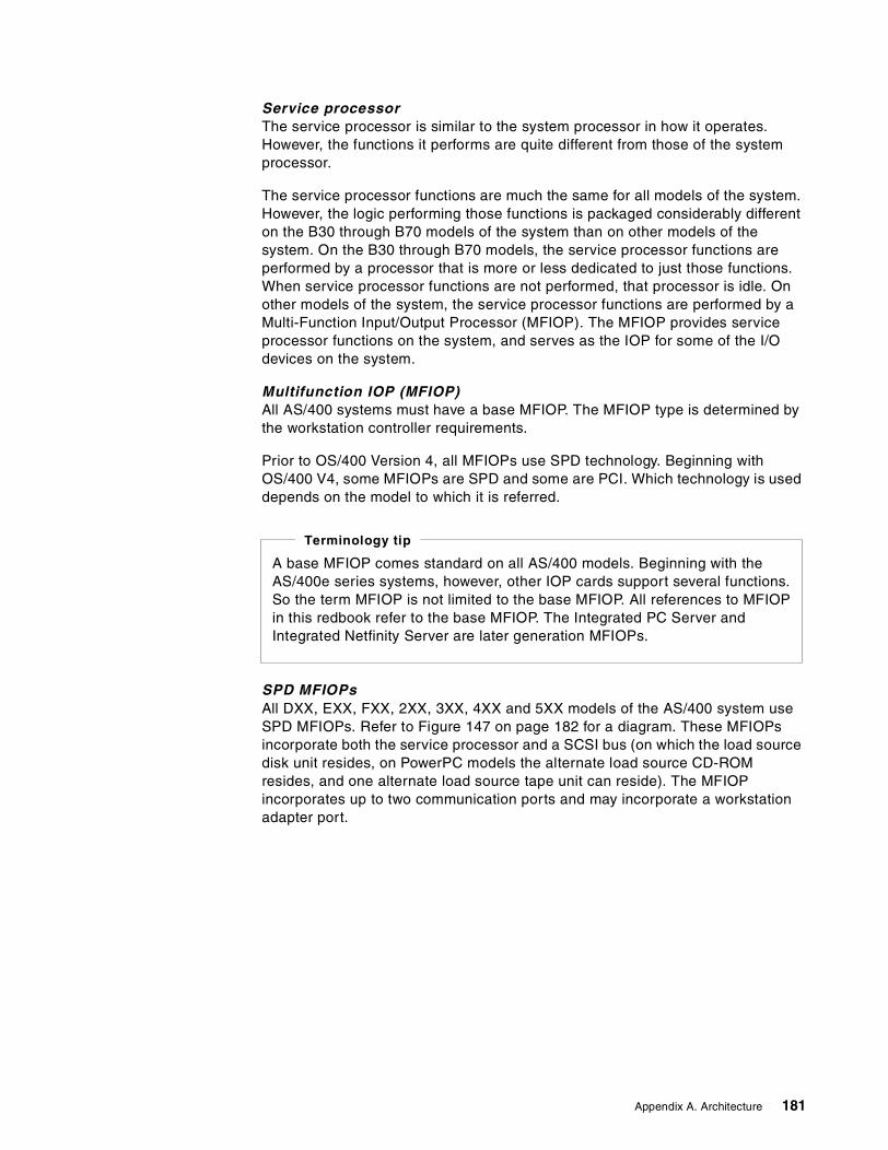
Service processorThe service processor is similar to the system processor in how it operates.However, the functions it performs are quite different from those of the systemprocessor.
The service processor functions are much the same for all models of the system.However, the logic performing those functions is packaged considerably differenton the B30 through B70 models of the system than on other models of thesystem. On the B30 through B70 models, the service processor functions areperformed by a processor that is more or less dedicated to just those functions.When service processor functions are not performed, that processor is idle. Onother models of the system, the service processor functions are performed by aMulti-Function Input/Output Processor (MFIOP). The MFIOP provides serviceprocessor functions on the system, and serves as the IOP for some of the I/Odevices on the system.
Multifunction IOP (MFIOP)All AS/400 systems must have a base MFIOP. The MFIOP type is determined bythe workstation controller requirements.
Prior to OS/400 Version 4, all MFIOPs use SPD technology. Beginning withOS/400 V4, some MFIOPs are SPD and some are PCI. Which technology is useddepends on the model to which it is referred.
SPD MFIOPsAll DXX, EXX, FXX, 2XX, 3XX, 4XX and 5XX models of the AS/400 system useSPD MFIOPs. Refer to Figure 147 on page 182 for a diagram. These MFIOPsincorporate both the service processor and a SCSI bus (on which the load sourcedisk unit resides, on PowerPC models the alternate load source CD-ROMresides, and one alternate load source tape unit can reside). The MFIOPincorporates up to two communication ports and may incorporate a workstationadapter port.
A base MFIOP comes standard on all AS/400 models. Beginning with theAS/400e series systems, however, other IOP cards support several functions.So the term MFIOP is not limited to the base MFIOP. All references to MFIOPin this redbook refer to the base MFIOP. The Integrated PC Server andIntegrated Netfinity Server are later generation MFIOPs.
Terminology tip
Appendix A. Architecture 181
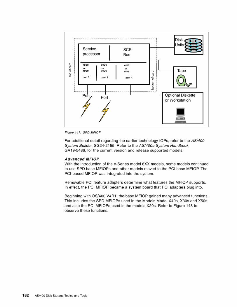
Figure 147. SPD MFIOP
For additional detail regarding the earlier technology IOPs, refer to the AS/400System Builder, SG24-2155. Refer to the AS/400e System Handbook,GA19-5486, for the current version and release supported models.
Advanced MFIOPWith the introduction of the e-Series model 6XX models, some models continuedto use SPD base MFIOPs and other models moved to the PCI base MFIOP. ThePCI-based MFIOP was integrated into the system.
Removable PCI feature adapters determine what features the MFIOP supports.In effect, the PCI MFIOP became a system board that PCI adapters plug into.
Beginning with OS/400 V4R1, the base MFIOP gained many advanced functions.This includes the SPD MFIOPs used in the Models Model X40s, X30s and X50sand also the PCI MFIOPs used in the models X20s. Refer to Figure 148 toobserve these functions.
Serviceprocessor
SCSIBus
2XXXor
6XXX
port C
Port
6147or
9149
port A
2XXXor
6XXX
port B
Port
top
ofca
rd
botto
mof
card Tape
DiskUnits
Optional Disketteor Workstation
182 AS/400 Disk Storage Topics and Tools
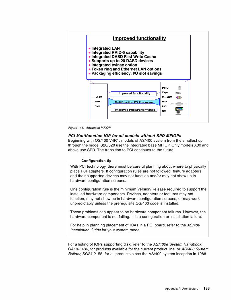
Figure 148. Advanced MFIOP
PCI Multifunction IOP for all models without SPD MFIOPsBeginning with OS/400 V4R1, models of AS/400 system from the smallest upthrough the model S20/620 use the integrated base MFIOP. Only models X30 andabove use SPD. The transition to PCI continues to the future.
For a listing of IOPs supporting disk, refer to the AS/400e System Handbook,GA19-5486, for products available for the current product line, or AS/400 SystemBuilder, SG24-2155, for all products since the AS/400 system inception in 1988.
Improved functionality
Integrated LANIntegrated RAID-5 capabilityIntegrated DASD Fast Write CacheSupports up to 20 DASD devicesIntegrated twinax optionToken ring and Ethernet LAN optionsPackaging efficiency, I/O slot savings
Improved Price/Performance
DASD
Tape
CD-ROM
WAN
LAN
WS
64 bit
RISC
SMP
Multifunction I/O Processor
Improved functionality
With PCI technology, there must be careful planning about where to physicallyplace PCI adapters. If configuration rules are not followed, feature adaptersand their supported devices may not function and/or may not show up inhardware configuration screens.
One configuration rule is the minimum Version/Release required to support theinstalled hardware components. Devices, adapters or features may notfunction, may not show up in hardware configuration screens, or may workunpredictably unless the prerequisite OS/400 code is installed.
These problems can appear to be hardware component failures. However, thehardware component is not failing. It is a configuration or installation failure.
For help in planning placement of IOAs in a PCI board, refer to the AS/400Installation Guide for your system model.
Configuration tip
Appendix A. Architecture 183
A.4.2.2 Considerations when installing DASD IOPsThe physical placement of an IOP affects the performance of devices attached toit, as well as other controllers on the same bus. Consider the following rulesregarding DASD IOPs and placement for best performance:
• Physical location
For proper configuration, locate DASD IOPs directly on the bus. Disk unitsexperience timing failures when installed on a bus extension, because the busextension’s clocking function differs from that of the bus.
• LIC on IOPs
Licensed Internal Code is loaded to the IOP during an IPL of the system. Onoccasion, an IOP loses the LIC stored in volatile memory on the IOP card.
LIC is restored to some IOPs without an IPL. When the RESET parameter onthe VRYCFG command is set to *YES, the VRYCFG command reloads LIC toworkstation controller IOPs and communication controller IOPs.
Note: The microcode for magnetic storage controller IOPs cannot be resetwith a VRYCFG. An IPL is necessary to reload LIC to a magnetic storagecontroller IOP.
A.5 DASD I/O cables within the AS/400 system
DASD I/O cables connect the I/O devices to their respective IOP/IOAs. Thissection gives an overview of the device cables within the AS/400 system andspecial considerations pertaining to the device cables. Detailed information oninterface features is in the AS/400 System Builder, SG24-2155, and AS/400eSystem Handbook, GA19-5486.
• DFCI (Device Function Controller Interface)
I/O cables on earlier disk devices (9332, 9335, and 9336) carry data andinformation using DFCI.
Note: The 9336 I/O cable is DFCI even though the 9336 drive itself is a SCSIdrive. This is because the #6112 IOP driving the 9336 uses DFCI protocol.
• SCSI (Small Computer System Interface)
I/O cables from the #6500 IOP to the 9337 models 0XX and 1XX DASD carrydata/information using the SCSI protocol.
• SCSI wide
The 9337 2XX and 4XX models use the SCSI wide protocol. The #6501,#6502 and #6512 IOP supports SCSI wide. SCSI wide has a wider bandwidth,thus enabling more data throughput. Because of the wider bandwidth, thecable that the 2XX, 4XX and 5XX models use is physically different than themodel 0XX or 1XX. When upgrading from a 0XX or 1XX model to a 2XX, 4XX,or 5XX model, be sure you have the appropriate cable available.
• Cable lengths
IBM I/O cables come in standard lengths. For example, the 9337 model 2XXIOP cables come in lengths of 2, 4, 6, or 20 meters. However, if the standardIBM cables do not meet the customer's needs, cables can be special orderedfrom IBM, as long as they meet industry standards. Industry standards, set byANSI, for these same cables allow for 25 meters. If a customer needs the
184 AS/400 Disk Storage Topics and Tools
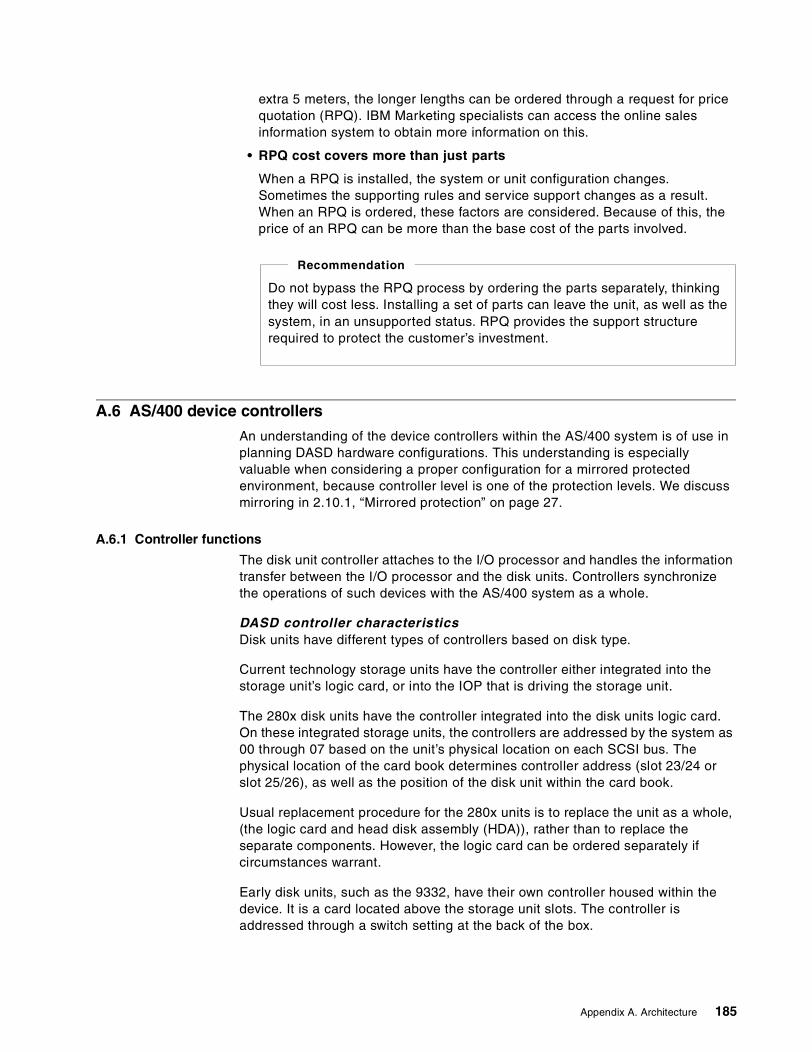
extra 5 meters, the longer lengths can be ordered through a request for pricequotation (RPQ). IBM Marketing specialists can access the online salesinformation system to obtain more information on this.
• RPQ cost covers more than just parts
When a RPQ is installed, the system or unit configuration changes.Sometimes the supporting rules and service support changes as a result.When an RPQ is ordered, these factors are considered. Because of this, theprice of an RPQ can be more than the base cost of the parts involved.
A.6 AS/400 device controllers
An understanding of the device controllers within the AS/400 system is of use inplanning DASD hardware configurations. This understanding is especiallyvaluable when considering a proper configuration for a mirrored protectedenvironment, because controller level is one of the protection levels. We discussmirroring in 2.10.1, “Mirrored protection” on page 27.
A.6.1 Controller functions
The disk unit controller attaches to the I/O processor and handles the informationtransfer between the I/O processor and the disk units. Controllers synchronizethe operations of such devices with the AS/400 system as a whole.
DASD controller characteristicsDisk units have different types of controllers based on disk type.
Current technology storage units have the controller either integrated into thestorage unit’s logic card, or into the IOP that is driving the storage unit.
The 280x disk units have the controller integrated into the disk units logic card.On these integrated storage units, the controllers are addressed by the system as00 through 07 based on the unit’s physical location on each SCSI bus. Thephysical location of the card book determines controller address (slot 23/24 orslot 25/26), as well as the position of the disk unit within the card book.
Usual replacement procedure for the 280x units is to replace the unit as a whole,(the logic card and head disk assembly (HDA)), rather than to replace theseparate components. However, the logic card can be ordered separately ifcircumstances warrant.
Early disk units, such as the 9332, have their own controller housed within thedevice. It is a card located above the storage unit slots. The controller isaddressed through a switch setting at the back of the box.
Do not bypass the RPQ process by ordering the parts separately, thinkingthey will cost less. Installing a set of parts can leave the unit, as well as thesystem, in an unsupported status. RPQ provides the support structurerequired to protect the customer’s investment.
Recommendation
Appendix A. Architecture 185
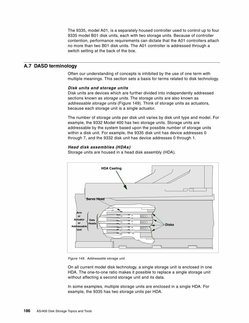
The 9335, model A01, is a separately housed controller used to control up to four9335 model B01 disk units, each with two storage units. Because of controllercontention, performance requirements can dictate that the A01 controllers attachno more than two B01 disk units. The A01 controller is addressed through aswitch setting at the back of the box.
A.7 DASD terminology
Often our understanding of concepts is inhibited by the use of one term withmultiple meanings. This section sets a basis for terms related to disk technology.
Disk units and storage unitsDisk units are devices which are further divided into independently addressedsections known as storage units. The storage units are also known asaddressable storage units (Figure 149). Think of storage units as actuators,because each storage unit is a single actuator.
The number of storage units per disk unit varies by disk unit type and model. Forexample, the 9332 Model 400 has two storage units. Storage units areaddressable by the system based upon the possible number of storage unitswithin a disk unit. For example, the 9335 disk unit has device addresses 0through 7, and the 9332 disk unit has device addresses 0 through 1.
Head disk assemblies (HDAs)Storage units are housed in a head disk assembly (HDA).
Figure 149. Addressable storage unit
On all current model disk technology, a single storage unit is enclosed in oneHDA. The one-to-one ratio makes it possible to replace a single storage unitwithout affecting a second storage unit and its data.
In some examples, multiple storage units are enclosed in a single HDA. Forexample, the 9335 has two storage units per HDA.
0 12 346 78 910 11
1312
5
HDA Casting
Disks
Servo Head
DataHeads
Armor
Actuatoror
AddressableUnit
186 AS/400 Disk Storage Topics and Tools
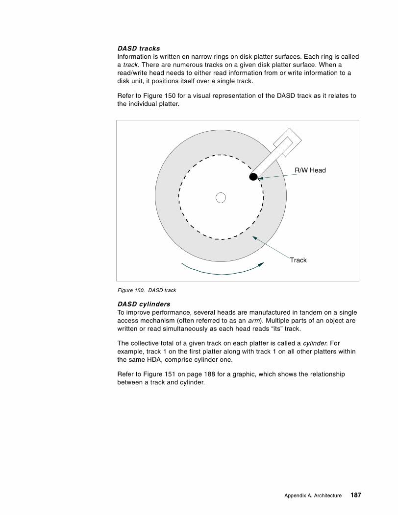
DASD tracksInformation is written on narrow rings on disk platter surfaces. Each ring is calleda track. There are numerous tracks on a given disk platter surface. When aread/write head needs to either read information from or write information to adisk unit, it positions itself over a single track.
Refer to Figure 150 for a visual representation of the DASD track as it relates tothe individual platter.
Figure 150. DASD track
DASD cylindersTo improve performance, several heads are manufactured in tandem on a singleaccess mechanism (often referred to as an arm). Multiple parts of an object arewritten or read simultaneously as each head reads “its” track.
The collective total of a given track on each platter is called a cylinder. Forexample, track 1 on the first platter along with track 1 on all other platters withinthe same HDA, comprise cylinder one.
Refer to Figure 151 on page 188 for a graphic, which shows the relationshipbetween a track and cylinder.
Track
R/W Head
Appendix A. Architecture 187
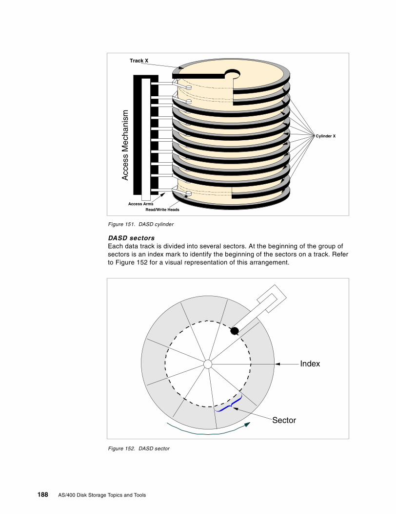
Figure 151. DASD cylinder
DASD sectorsEach data track is divided into several sectors. At the beginning of the group ofsectors is an index mark to identify the beginning of the sectors on a track. Referto Figure 152 for a visual representation of this arrangement.
Figure 152. DASD sector
Access ArmsRead/Write Heads
Track X
Cylinder X
Acc
ess
Mec
hani
sm
Sector
Index
188 AS/400 Disk Storage Topics and Tools
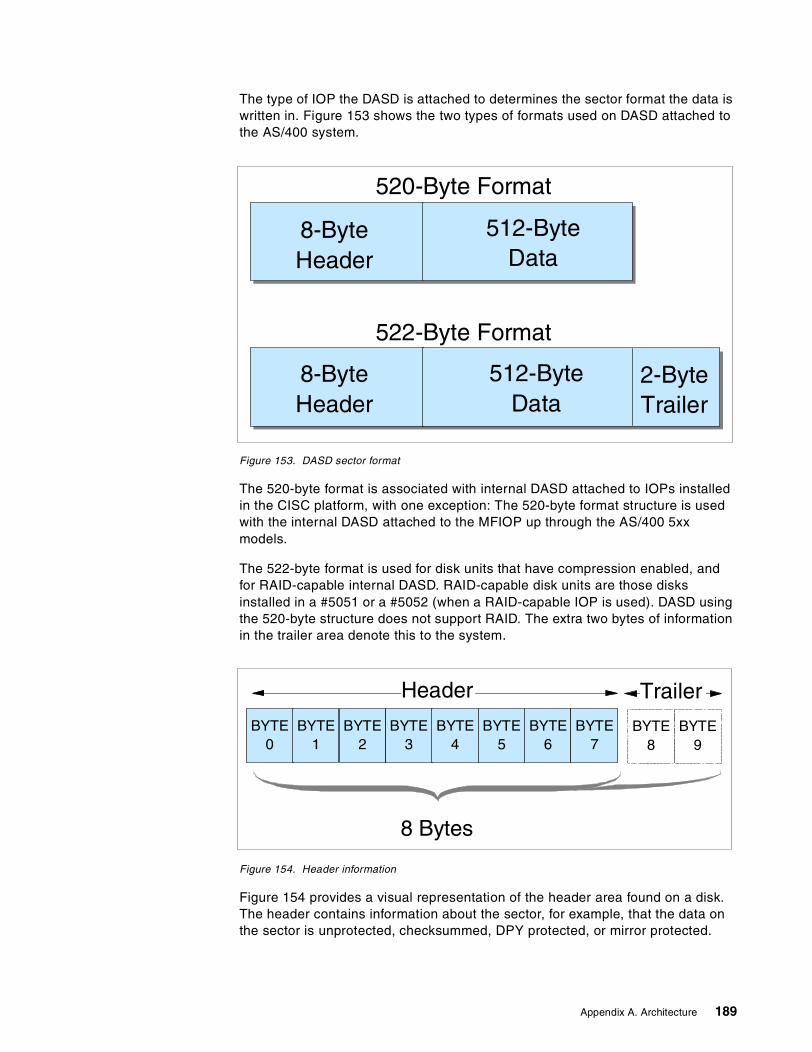
The type of IOP the DASD is attached to determines the sector format the data iswritten in. Figure 153 shows the two types of formats used on DASD attached tothe AS/400 system.
Figure 153. DASD sector format
The 520-byte format is associated with internal DASD attached to IOPs installedin the CISC platform, with one exception: The 520-byte format structure is usedwith the internal DASD attached to the MFIOP up through the AS/400 5xxmodels.
The 522-byte format is used for disk units that have compression enabled, andfor RAID-capable internal DASD. RAID-capable disk units are those disksinstalled in a #5051 or a #5052 (when a RAID-capable IOP is used). DASD usingthe 520-byte structure does not support RAID. The extra two bytes of informationin the trailer area denote this to the system.
Figure 154. Header information
Figure 154 provides a visual representation of the header area found on a disk.The header contains information about the sector, for example, that the data onthe sector is unprotected, checksummed, DPY protected, or mirror protected.
520-Byte Format
522-Byte Format
8-ByteHeader
512-ByteData
512-ByteData
8-ByteHeader
2-ByteTrailer
BYTE0
BYTE1
BYTE2
BYTE3
BYTE4
BYTE5
BYTE6
BYTE8
BYTE9
BYTE7
Header
8 Bytes
Trailer
Appendix A. Architecture 189
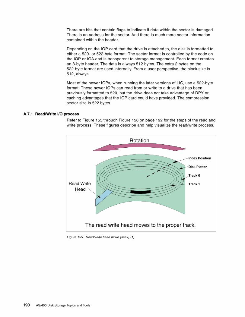
There are bits that contain flags to indicate if data within the sector is damaged.There is an address for the sector. And there is much more sector informationcontained within the header.
Depending on the IOP card that the drive is attached to, the disk is formatted toeither a 520- or 522-byte format. The sector format is controlled by the code onthe IOP or IOA and is transparent to storage management. Each format createsan 8-byte header. The data is always 512 bytes. The extra 2 bytes on the522-byte format are used internally. From a user perspective, the block size is512, always.
Most of the newer IOPs, when running the later versions of LIC, use a 522-byteformat. These newer IOPs can read from or write to a drive that has beenpreviously formatted to 520, but the drive does not take advantage of DPY orcaching advantages that the IOP card could have provided. The compressionsector size is 522 bytes.
A.7.1 Read/Write I/O process
Refer to Figure 155 through Figure 158 on page 192 for the steps of the read andwrite process. These figures describe and help visualize the read/write process.
Figure 155. Read/write head move (seek) (1)
Read WriteHead
The read write head moves to the proper track.
Index Position
Disk Platter
Track 0
Track 1
Rotation
190 AS/400 Disk Storage Topics and Tools
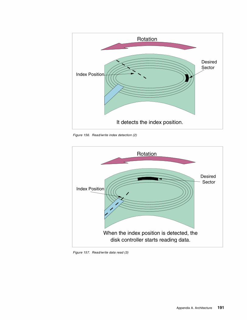
Figure 156. Read/write index detection (2)
Figure 157. Read/write data read (3)
Index Position
DesiredSector
It detects the index position.
Rotation
When the index position is detected, thedisk controller starts reading data.
Index Position
DesiredSector
Rotation
Appendix A. Architecture 191
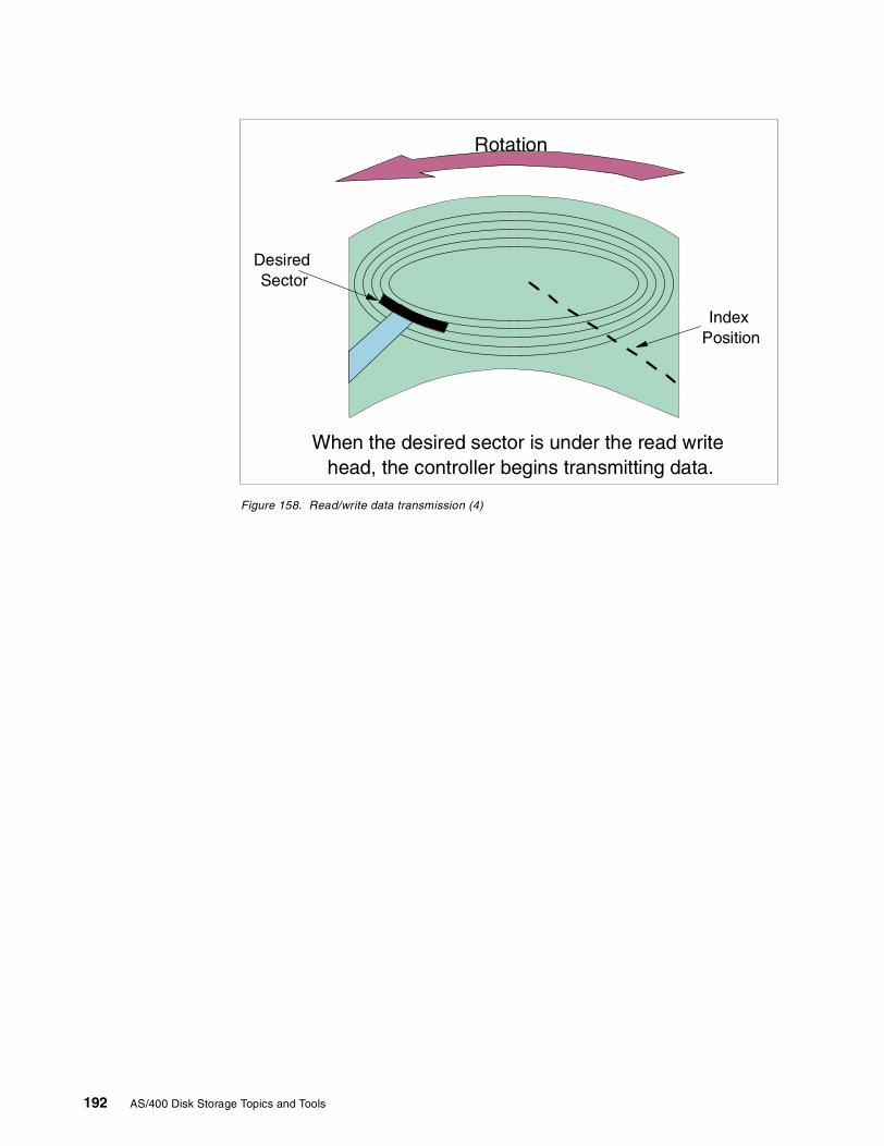
Figure 158. Read/write data transmission (4)
When the desired sector is under the read writehead, the controller begins transmitting data.
DesiredSector
Rotation
IndexPosition
192 AS/400 Disk Storage Topics and Tools
Appendix B. Storage management terms used in SLIC
This appendix provides descriptions of some frequently used AS/400storage-related terminology:
Address The location in the storage of a computer where particular data isstored.
Auxiliary Storage Pool (ASP)A group of storage units defined from the disk units that make upauxiliary storage. ASPs provide a means of isolating certain objects ona specific disk unit as a method to prevent the loss of data due to diskmedia failures on other disk units.
Extent This is a variable-sized piece of DASD to which a virtual addressrange has been assigned.
Free space directoryThis is a pageable machine index which tracks all unassigned sectorson all disk units. It is used in CISC systems only.
Magnetic tapePlastic tape coated on one side with a magnetic material that storesinformation as varying patterns of magnetization.
Main storage poolA division of main storage which allows the user to reserve mainstorage for processing a job or group of jobs, or to use the poolsdefined by the system. As of OS/400 V4R4, up to 64 pools can be setup in one AS/400 system.
Page (noun)A page is made up of eight disk sectors (4 KB) or 4 KB of mainmemory.
Page (verb)
An action of moving a page of data from main memory to disk or viceversa.
Permanent addressAn address used to locate a piece of data that survives an IPL.
Permanent directoryUsed by storage management to keep track of permanent addressescurrently being used and their corresponding locations on DASD.
Real address (storage)Main storage.
Sector The smallest amount of information that can be written to or read froma disk or diskette during a single read or write operation. A sectorconsists of 512 bytes of data and an 8-byte sector header to give atotal size of 520 bytes. There are some other bits that belong tohardware (used when disk compression is activated, for example), butthey can be ignored for the purposes of storage management.
Segment Identifier (SID)Refers to the 4 or 5 high-order bytes of an 8-byte virtual storageaddress. The big SID is composed of a 5-byte SID and 3-byte offset. Itencompasses an address range of 16 MB with 4096 occurrences of 4
© Copyright IBM Corp. 2000 193
KB pages. The little SID consists of 5 bytes called the Segment GroupIdentifier (SGID), which addresses 16 MB of storage. One SGIDconsists of up to 256 little SIDs, each of which addresses 64 KB ofstorage. The number of little SIDs is expressed in byte 5 (bits 40 to 47)of the address.
Static directoryThis is used to store VLIC persistent data such as the disk locations ofthe permanent directory and so on.
StorageDevices such as disks and tapes that store data magnetically oroptically. Although slower than a computer’s internal electronicmemory, storage devices provide virtually unlimited capacity andpreserve data integrity.
Temporary addressAn address used to locate a piece of data that does not survive anIPL.
Temporary directoryUsed by storage management to keep track of temporary addressescurrently being used and their corresponding locations on DASD.
Temporary libraryA library that is automatically created for each job to containtemporary objects that are created by the system for that job. Theobjects in the temporary library are deleted when the job ends. Thesystem name for the temporary library is QTEMP.
Temporary objectsObjects, such as data paths or compiler work areas, that areautomatically deleted by the system when the operating system isloaded.
Virtual address (storage)An addressing scheme that allows external disk storage to appear asmain storage.
194 AS/400 Disk Storage Topics and Tools
Appendix C. Non-removable storage (DASD)
In this section, we identify and describe the various DASD options available forAS/400 system installation. Topics include both new and old DASD that aresupported attached to current AS/400 systems.
C.1 DASD available for the AS/400 system
The listed DASD in this section include those supported in current technologyAS/400 systems. For information regarding DASD supported in previoustechnology AS/400 system platforms, refer to the AS/400 System Builder,SG24-2155.
Available disk enclosures for the AS/400 systems are discussed in the followingsections. Internal and external storage options are discussed.
C.1.1 280X
The DASD described in this section are not all supported in current AS/400systems. The #2800 and #2801 repackaged DASD are not supported in thecurrent AS/400e series systems. The #2802 DASD is supported in the AS/400eseries.
The internal DASD storage units are available in three capacities: 1.3 GB,988 MB, and 320 MB. Each card book contains two storage units of the samecapacity. The AS/400 system has a minimum configuration of 1.2 GB of internalstorage. This is accomplished with two #2800 card books, one #2801, or one#2802 card book. If a #2801 or #2802 card book is used as the baseconfiguration, then an additional, optional #2800, #2801 or #2802 can beincluded. The system is capable of accommodating a maximum of two cardbooks.
As the AS/400 DASD evolves, more and more circuitry that was formerly onseparate field replaceable units (FRUs) are a part of the base unit. For example,the read/write control cards that were attached to the 9335 HDA are included inthe logic card of the #2800. The controller that is housed in a separate model ofthe 9335 is also included in the same logic card on the 2800. The individual diskunits have become an entire separate subsystem within themselves. The 9337High Availability (HA) model (another term sometimes used in place of deviceparity protection (DPY) models) is an example of this.
C.1.2 9337 DASD
While 9337 DASD can no longer be ordered new from IBM, they are the onlyexternal storage subsystems still supported to attach to AS/400 systems 7xxmodels. The characteristics remain the same on 9337 DASD regardless of theplatform to which it is attached.
Refer to Figure 159 on page 196 to observe some of the physical characteristicsof the 9337 subsystem.
© Copyright IBM Corp. 2000 195
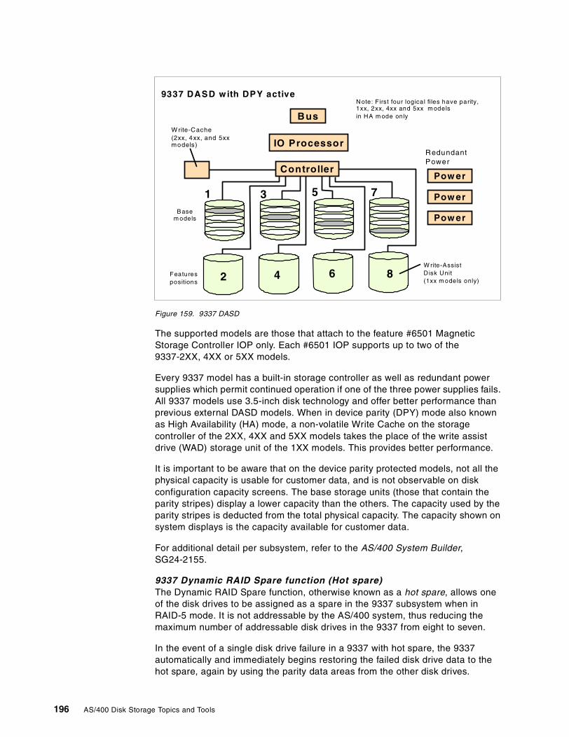
Figure 159. 9337 DASD
The supported models are those that attach to the feature #6501 MagneticStorage Controller IOP only. Each #6501 IOP supports up to two of the9337-2XX, 4XX or 5XX models.
Every 9337 model has a built-in storage controller as well as redundant powersupplies which permit continued operation if one of the three power supplies fails.All 9337 models use 3.5-inch disk technology and offer better performance thanprevious external DASD models. When in device parity (DPY) mode also knownas High Availability (HA) mode, a non-volatile Write Cache on the storagecontroller of the 2XX, 4XX and 5XX models takes the place of the write assistdrive (WAD) storage unit of the 1XX models. This provides better performance.
It is important to be aware that on the device parity protected models, not all thephysical capacity is usable for customer data, and is not observable on diskconfiguration capacity screens. The base storage units (those that contain theparity stripes) display a lower capacity than the others. The capacity used by theparity stripes is deducted from the total physical capacity. The capacity shown onsystem displays is the capacity available for customer data.
For additional detail per subsystem, refer to the AS/400 System Builder,SG24-2155.
9337 Dynamic RAID Spare function (Hot spare)The Dynamic RAID Spare function, otherwise known as a hot spare, allows oneof the disk drives to be assigned as a spare in the 9337 subsystem when inRAID-5 mode. It is not addressable by the AS/400 system, thus reducing themaximum number of addressable disk drives in the 9337 from eight to seven.
In the event of a single disk drive failure in a 9337 with hot spare, the 9337automatically and immediately begins restoring the failed disk drive data to thehot spare, again by using the parity data areas from the other disk drives.
9337 DASD with DPY active
Pow er
Pow er
Pow er
W rite-Cache(2xx, 4xx, and 5xxmodels)
N ote: F irst four logical files have parity,1xx, 2xx, 4xx and 5xx m odelsin HA m ode only
RedundantPower
W rite-AssistD isk Unit(1xx m odels only)
Featurespositions
Basem odels
Bus
IO Processor
Controller
1 3 5 7
2 4 6 8
196 AS/400 Disk Storage Topics and Tools
A customer can activate a hot spare feature in RAIDable 9337s when RAID isactivated. Hot spare is not an option if mirror protection is used. In a 9337 withhot spare, if a single disk unit fails, the data of the failed unit is rebuilt on thespare drive from the parity stripes of the others. This is done automatically andmay often be completed before the service representative arrives.
Since the data rebuild process can begin before the failed disk drive is physicallyreplaced, it reduces the time that the 9337 is in the “exposed” mode to the time ittakes to rebuild the hot spare. The “exposed” mode is when there is the potentialof another disk drive failing in the same 9337 which could cause the 9337 tocease operation. After physical replacement of the failed drive, it becomes thenew hot spare.
This Dynamic RAID Spare Function is also available on 9337 210, 215, 220, 225,or 240 models that do not have the 4M cache installed on the controller as anRPQ (843795).
How to define a hot-spare configuration is documented in the Backup andRecovery Guide, SC41-5304.
C.1.3 Enterprise Storage Server
The Enterprise Storage Server (ESS) is a Storage Area Network (SAN) storagesolution. It supports fibre-channel attachment. Capacity ranges from 400 GB toover 11 TB. The ESS architecture supports high availability requirements byusing redundant components. Date replication services extend access to data,while using a concurrent copy. Rapid data duplication provides extensivecapabilities to serve, manage, and protect information in a 7 by 24 environment.The ESS incorporates and builds on the capabilities of the Versatile StorageServer, as discussed in the following section.
The Enterprise Storage Server (ESS) attaches to the AS/400 system using a#6501 Magnetic Storage Controller (SPD). The #6501 requires V3R1 or later.When attached to the #6501, the ESS emulates the 9337-5xx or 9337-5xx drivebased on the size of the disk units installed.
For further information on the Versatile Storage Server, refer to the AS/400eSystem Handbook, GA19-5486.
C.1.4 Versatile Storage Server
With the IBM Versatile Storage Server (VSS), disk storage can be consolidated touse Web-based management data sharing for similar servers and dynamiccapacity allocation function. The VSS delivers centralized management andstored data. It also provides sharing of disk storage for a variety of UNIX,Windows NT, and AS/400 servers. Built using the 7133 Serial Disk Subsystem,centralized management is simplified using IBM StorWatch, with aJava-compliant Internet browser.
The primary enclosure of the Versatile Storage Server includes the storageserver, two 7133 drawers, and the power control system. There is space for twoadditional 7133 disk drawers. The primary enclosure can be combined with up totwo 2105-100 expansion enclosures.
Appendix C. Non-removable storage (DASD) 197
The VSS attaches to the AS/400 system using a #6501 Magnetic StorageController (SPD). The #6501 requires V3R1 or later. When attached to the #6501,the Versatile Storage Server emulates the 9337-580 or 9337-590 based on thesize of the disk unit installed.
C.2 Internal DASD: SPCN versus Non-SPCN
SPCN or non-SPCN packaged DASD can be installed in DASD positionscontrolled by the MFIOP, only if working with an SPCN system. If using anon-SPCN system (Model 300), you cannot move SPCN packaged DASD intothe MFIOP supported slots because this will damage the SPCN packaged DASD.
Releases beyond V3R2 allow concurrent maintenance of DASD when protectionis in place for non-SPCN systems.
If you have a non-SPCN or SPCN tower with V4R1 or later, concurrent DASDrepair is available, as that function is built into the SLIC code. V4R1 can only beinstalled on 4XX models or above because V4R1 can only operate on a PowerPCversion of hardware.
Due to separate removable tray assemblies and separate power supplies,concurrent repair of AS/400 internal disks is available for the first time with the3XX models. Concurrent repair allows a failed storage unit, which has beenprotected by RAID-5 or mirroring, to be replaced by service personnel while thesystem is still running. Redundant power supplies in the system (model 3xx andhigher) provide backup power for the internal drives, should one power supplyfail.
Note: The version and release references in the following list of IOPs indicatesminimum level required for that IOP.
SPD IOPs available for internal DASD include:
• #6502: 2 MB cache RAID/Mirroring/Unprotected (V3R2)
• #6530: No cache Mirror protection only (V3R2)
• #6512: 4 MB cache RAID/Mirroring/Unprotected (V3R6, V3R7)
• #6532: 4 MB cache RAID/Mirroring/Unprotected (V4R1)
• Each connection to an AS/400 system using a #6501 supports a maximumof sixteen disk units. There can be a maximum of eight #3001 Host InterfaceAdapters per 2105 VSS. If eight #6501s are attached to eight #3001s, thisdedicates the 2105 VSS to the AS/400 system and gives a maximumcapacity of 536.3 GB when emulating 9337-580s, 1099.5 GB whenemulating 9337-580s, and 1099.5 GB when emulating 9337-590s.
• In most cases, the minimum cache memory of 512 MB is best for use withthe AS/400 system, but the expert cache function of OS/400 normallyprovides better performance. The Versatile Storage Server ExpansionEnclosure includes space for seven 7133-010, 7133-020, 7133-D40drawers and a power control system.
Notes
198 AS/400 Disk Storage Topics and Tools
• #6533: 4 MB cache RAID/Mirroring/Unprotected (V4R2), integrated hardwaredisk compression enabled with V4R3
• #9751 MFIOP with RAID (Ultra SCSI) V4R1
• #9754 MFIOP with RAID (Ultra SCSI) V4R2, integrated hardware diskcompression enabled with V4R3
Refer to A.4, “AS/400 IOP and IOA” on page 179, for details of the IOP cards andtheir capabilities.
For a complete listing of internal DASD, refer to AS/400 Installation and Upgrade,SY44-5950. Locate and reference Appendix C, “Configuration Rules for AS/400Models”, and find the chart for internal DASD devices. Be certain to reference thecorrect level of documentation for your system.
C.3 Expansion TowersExpansion towers expand the capacity of the AS/400 system by providinghousing for additional storage devices. The towers are architectural for eitherSPD or PCI technology.
For further details and to understand which disk and tape units are supported,refer to the AS/400e System Handbook, GA19-5486.
C.3.1 #508x Storage Expansion Tower
The technology found in this tower is strictly SPD, regarding the bus structure aswell as the IOPs that plug into the card cage. This tower was first introduced inthe CISC platform in the form of a #5060. It was designed to provide an additionalstorage tower. There is no room for workstation or communication or any othertype of IOP.
Three slots are included in the card cage for SPD IOP cards. The first slotcontains the bus receiver card for data and signal traffic to and from the AS/400system unit it is attached to. The second slot is designated as the DASD IOP slotthat controls up to 16 DASD found inside the frame of the tower. The third slot isdesignated to control the #5051 and #5052 that provide slots for an additional 16DASD.
The total number of DASD slots available in this box with a storage expansionunit installed is 32 DASD. This tower is considered an additional system I/O busand used in place of a #507x system expansion tower.
The storage expansion towers of today (#508x) operate under the samecharacteristics as described here.
C.3.2 #5065 Storage/PCI Expansion Tower
This technology, although PCI at the tower, uses the optical bus connections,which is SPD to the currently available AS/400 system units.
The #5065 Storage/PCI Expansion Tower is a disk expansion tower with PCIadapter support. With the #5065, you have support for lower-cost PCI cards andfaster disk units in denser packaging, along with Ultra2 SCSI performance. It iscapable of supporting 45 one-inch Ultra2 Disk units, and has 12 PCI IOA slots
Appendix C. Non-removable storage (DASD) 199
(supporting up to three PCI RAID Disk Unit Controllers) and two removable mediaslots.
The #5065 Tower requires V4R4, and attaches to models 720, 730, and 740 (plus6XX and SXX) via an SPD optical bus. With the #2748 IOP installed, the ReadCache Device can be installed and utilized. For additional restrictions andconsiderations for use of this tower refer to the AS/400e System Handbook,GA19-5486, or the AS/400 System Builder, SG24-2155.
C.3.3 #5066 1.8 I/O Tower
The #5066 1.8 I/O Tower includes two 1063 Mbps optical bus cards, variouscables, including optical cables, and the 1.8M I/O Tower. The #5066 provides 24PCI IOA slots, space for 90 disk units, space for four removable media devices,battery backup, redundant/hot swap power supplies, and two PCILAN/WAN/Workstation IOPs (CCIN #2824). It supports Ultra2 SCSI disk units.The #5066 also supports up to four removable media devices (internal tape orCD-ROM).
The #5066 is actually two #5065 Storage/PCI Expansion Towers installed in a#5066 1.8M I/O Tower. It reports to the system as two #5065s.
200 AS/400 Disk Storage Topics and Tools
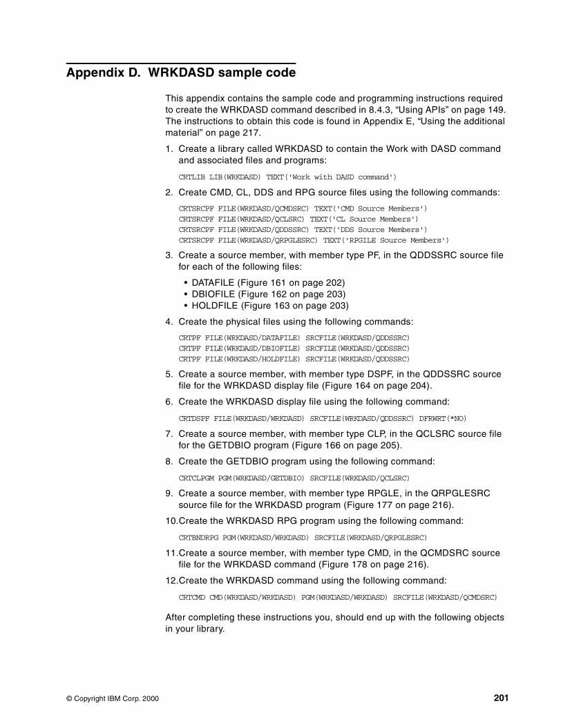
Appendix D. WRKDASD sample code
This appendix contains the sample code and programming instructions requiredto create the WRKDASD command described in 8.4.3, “Using APIs” on page 149.The instructions to obtain this code is found in Appendix E, “Using the additionalmaterial” on page 217.
1. Create a library called WRKDASD to contain the Work with DASD commandand associated files and programs:
CRTLIB LIB(WRKDASD) TEXT('Work with DASD command')
2. Create CMD, CL, DDS and RPG source files using the following commands:
CRTSRCPF FILE(WRKDASD/QCMDSRC) TEXT('CMD Source Members')CRTSRCPF FILE(WRKDASD/QCLSRC) TEXT('CL Source Members')CRTSRCPF FILE(WRKDASD/QDDSSRC) TEXT('DDS Source Members')CRTSRCPF FILE(WRKDASD/QRPGLESRC) TEXT('RPGILE Source Members')
3. Create a source member, with member type PF, in the QDDSSRC source filefor each of the following files:
• DATAFILE (Figure 161 on page 202)• DBIOFILE (Figure 162 on page 203)• HOLDFILE (Figure 163 on page 203)
4. Create the physical files using the following commands:
CRTPF FILE(WRKDASD/DATAFILE) SRCFILE(WRKDASD/QDDSSRC)CRTPF FILE(WRKDASD/DBIOFILE) SRCFILE(WRKDASD/QDDSSRC)CRTPF FILE(WRKDASD/HOLDFILE) SRCFILE(WRKDASD/QDDSSRC)
5. Create a source member, with member type DSPF, in the QDDSSRC sourcefile for the WRKDASD display file (Figure 164 on page 204).
6. Create the WRKDASD display file using the following command:
CRTDSPF FILE(WRKDASD/WRKDASD) SRCFILE(WRKDASD/QDDSSRC) DFRWRT(*NO)
7. Create a source member, with member type CLP, in the QCLSRC source filefor the GETDBIO program (Figure 166 on page 205).
8. Create the GETDBIO program using the following command:
CRTCLPGM PGM(WRKDASD/GETDBIO) SRCFILE(WRKDASD/QCLSRC)
9. Create a source member, with member type RPGLE, in the QRPGLESRCsource file for the WRKDASD program (Figure 177 on page 216).
10.Create the WRKDASD RPG program using the following command:
CRTBNDRPG PGM(WRKDASD/WRKDASD) SRCFILE(WRKDASD/QRPGLESRC)
11.Create a source member, with member type CMD, in the QCMDSRC sourcefile for the WRKDASD command (Figure 178 on page 216).
12.Create the WRKDASD command using the following command:
CRTCMD CMD(WRKDASD/WRKDASD) PGM(WRKDASD/WRKDASD) SRCFILE(WRKDASD/QCMDSRC)
After completing these instructions you, should end up with the following objectsin your library.
© Copyright IBM Corp. 2000 201
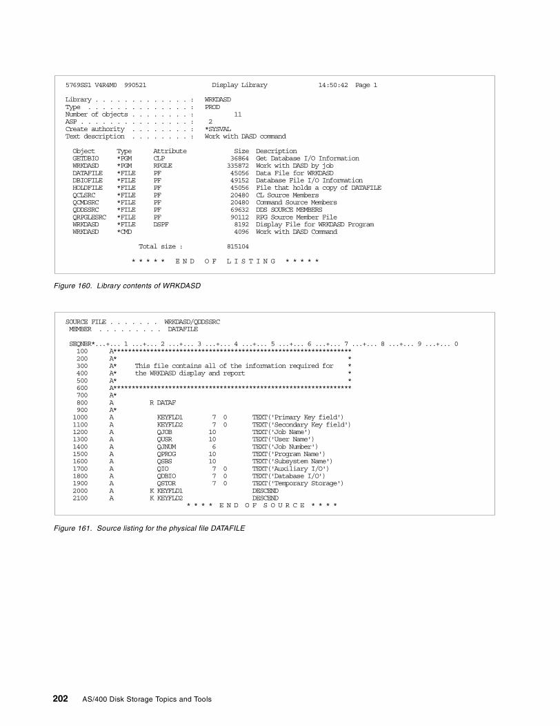
Figure 160. Library contents of WRKDASD
Figure 161. Source listing for the physical file DATAFILE
5769SS1 V4R4M0 990521 Display Library 14:50:42 Page 1
Library . . . . . . . . . . . . . : WRKDASDType . . . . . . . . . . . . . . : PRODNumber of objects . . . . . . . . : 11ASP . . . . . . . . . . . . . . . : 2Create authority . . . . . . . . : *SYSVALText description . . . . . . . . : Work with DASD command
Object Type Attribute Size DescriptionGETDBIO *PGM CLP 36864 Get Database I/O InformationWRKDASD *PGM RPGLE 335872 Work with DASD by jobDATAFILE *FILE PF 45056 Data File for WRKDASDDBIOFILE *FILE PF 49152 Database File I/O InformationHOLDFILE *FILE PF 45056 File that holds a copy of DATAFILEQCLSRC *FILE PF 20480 CL Source MembersQCMDSRC *FILE PF 20480 Command Source MembersQDDSSRC *FILE PF 69632 DDS SOURCE MEMBERSQRPGLESRC *FILE PF 90112 RPG Source Member FileWRKDASD *FILE DSPF 8192 Display File for WRKDASD ProgramWRKDASD *CMD 4096 Work with DASD Command
Total size : 815104
* * * * * E N D O F L I S T I N G * * * * *
SOURCE FILE . . . . . . . WRKDASD/QDDSSRCMEMBER . . . . . . . . . DATAFILE
SEQNBR*...+... 1 ...+... 2 ...+... 3 ...+... 4 ...+... 5 ...+... 6 ...+... 7 ...+... 8 ...+... 9 ...+... 0100 A*****************************************************************200 A* *300 A* This file contains all of the information required for *400 A* the WRKDASD display and report *500 A* *600 A*****************************************************************700 A*800 A R DATAF900 A*1000 A KEYFLD1 7 0 TEXT('Primary Key field')1100 A KEYFLD2 7 0 TEXT('Secondary Key field')1200 A QJOB 10 TEXT('Job Name')1300 A QUSR 10 TEXT('User Name')1400 A QJNUM 6 TEXT('Job Number')1500 A QPROG 10 TEXT('Program Name')1600 A QSBS 10 TEXT('Subsystem Name')1700 A QIO 7 0 TEXT('Auxiliary I/O')1800 A QDBIO 7 0 TEXT('Database I/O')1900 A QSTOR 7 0 TEXT('Temporary Storage')2000 A K KEYFLD1 DESCEND2100 A K KEYFLD2 DESCEND
* * * * E N D O F S O U R C E * * * *
202 AS/400 Disk Storage Topics and Tools
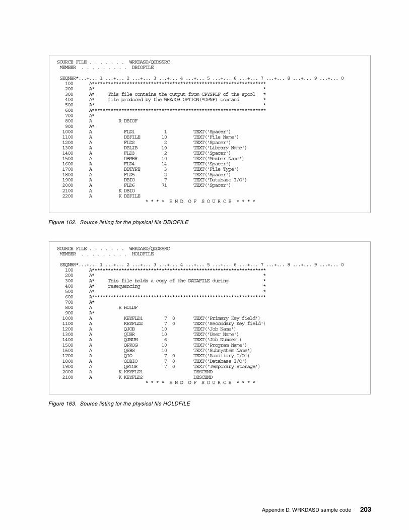
Figure 162. Source listing for the physical file DBIOFILE
Figure 163. Source listing for the physical file HOLDFILE
xSOURCE FILE . . . . . . . WRKDASD/QDDSSRCMEMBER . . . . . . . . . DBIOFILE
SEQNBR*...+... 1 ...+... 2 ...+... 3 ...+... 4 ...+... 5 ...+... 6 ...+... 7 ...+... 8 ...+... 9 ...+... 0100 A*****************************************************************200 A* *300 A* This file contains the output from CPYSPLF of the spool *400 A* file produced by the WRKJOB OPTION(*OPNF) command *500 A* *600 A*****************************************************************700 A*800 A R DBIOF900 A*1000 A FLD1 1 TEXT('Spacer')1100 A DBFILE 10 TEXT('File Name')1200 A FLD2 2 TEXT('Spacer')1300 A DBLIB 10 TEXT('Library Name')1400 A FLD3 2 TEXT('Spacer')1500 A DBMBR 10 TEXT('Member Name')1600 A FLD4 14 TEXT('Spacer')1700 A DBTYPE 3 TEXT('File Type')1800 A FLD5 2 TEXT('Spacer')1900 A DBIO 7 TEXT('Database I/O')2000 A FLD6 71 TEXT('Spacer')2100 A K DBIO2200 A K DBFILE
* * * * E N D O F S O U R C E * * * *
SOURCE FILE . . . . . . . WRKDASD/QDDSSRCMEMBER . . . . . . . . . HOLDFILE
SEQNBR*...+... 1 ...+... 2 ...+... 3 ...+... 4 ...+... 5 ...+... 6 ...+... 7 ...+... 8 ...+... 9 ...+... 0100 A*****************************************************************200 A* *300 A* This file holds a copy of the DATAFILE during *400 A* resequencing *500 A* *600 A*****************************************************************700 A*800 A R HOLDF900 A*1000 A KEYFLD1 7 0 TEXT('Primary Key field')1100 A KEYFLD2 7 0 TEXT('Secondary Key field')1200 A QJOB 10 TEXT('Job Name')1300 A QUSR 10 TEXT('User Name')1400 A QJNUM 6 TEXT('Job Number')1500 A QPROG 10 TEXT('Program Name')1600 A QSBS 10 TEXT('Subsystem Name')1700 A QIO 7 0 TEXT('Auxiliary I/O')1800 A QDBIO 7 0 TEXT('Database I/O')1900 A QSTOR 7 0 TEXT('Temporary Storage')2000 A K KEYFLD1 DESCEND2100 A K KEYFLD2 DESCEND
* * * * E N D O F S O U R C E * * * *
Appendix D. WRKDASD sample code 203
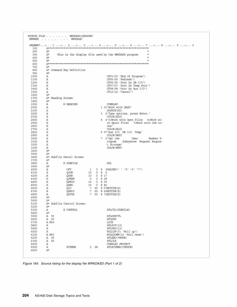
Figure 164. Source listing for the display file WRKDASD (Part 1 of 2)
SOURCE FILE . . . . . . . WRKDASD/QDDSSRCMEMBER . . . . . . . . . WRKDASD
SEQNBR*...+... 1 ...+... 2 ...+... 3 ...+... 4 ...+... 5 ...+... 6 ...+... 7 ...+... 8 ...+... 9 ...+... 0100 A*****************************************************************200 A* *300 A* This is the display file used by the WRKDASD program *400 A* *500 A* *600 A*****************************************************************700 A*800 A* Command Key Definition900 A*1000 A CF03(03 'End of Program')1100 A CF05(05 'Refresh')1200 A CF06(06 'Sort by DB I/O')1300 A CF07(07 'Sort by Temp Stor')1400 A CF08(08 'Sort by Aux I/O')1500 A CF12(12 'Cancel')1600 A*1700 A* Heading Screen1800 A*1900 A R HEADING OVERLAY2000 A 1 33'Work with DASD'2100 A DSPATR(HI)2200 A 3 2'Type options, press Enter.'2300 A COLOR(BLU)2400 A 4 4'5=Work with Open Files 6=Work wi-2500 A th Spool Files 7=Work with Job Lo-2600 A cks'2700 A COLOR(BLU)2800 A 6 57'Aux I/O DB I/O Temp'2900 A COLOR(WHT)3000 A 7 2'Opt Job User Number P-3100 A rogram Subsystem Request Reques-3200 A t Storage'3300 A COLOR(WHT)3400 A*3500 A*3600 A* Subfile Detail Screen3700 A*3800 A R SUBFILE SFL3900 A*4000 A OPT 1 I 8 3VALUES(' ' '5' '6' '7')4100 A QJOB 10 O 8 64200 A QUSR 10 O 8 174300 A QJNUM 6 O 8 284400 A QPROG 10 O 8 354500 A QSBS 10 O 8 464600 A QIO 7 0O 8 57EDTCDE(Z)4700 A QDBIO 7 0O 8 65EDTCDE(Z)4800 A QSTOR 7 0O 8 73EDTCDE(Z)4900 A*5000 A*5100 A* Subfile Control Screen5200 A*5300 A R CONTROL SFLCTL(SUBFILE)5400 A*5500 A 55 SFLDSPCTL5600 A 50 SFLDSP5700 A N50 LOCK5800 A SFLSIZ(12)5900 A SFLPAG(12)6000 A ROLLUP(31 'Roll up')6100 A N60 ROLLDOWN(32 'Roll down')6200 A 59 SFLEND(*MORE)6300 A 60 SFLCLR6400 A OVERLAY PROTECT6500 A RCDNBR 2 0H SFLRCDNBR(CURSOR)6600 A*
204 AS/400 Disk Storage Topics and Tools
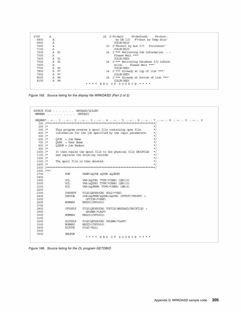
Figure 165. Source listing for the display file WRKDASD (Part 2 of 2)
Figure 166. Source listing for the CL program GETDBIO
6700 A 22 2'F3=Exit F5=Refresh F6=Sort-6800 A by DB I/O F7=Sort by Temp Stor'6900 A COLOR(BLU)7000 A 23 2'F8=Sort by Aux I/O F12=Cancel'7100 A COLOR(BLU)7200 A 91 24 2'*** Retrieving Job Information - -7300 A Please Wait ***'7400 A 91 COLOR(RED)7500 A 92 24 2'*** Retrieving Database I/O inform-7600 A ation - Please Wait ***'7700 A 92 COLOR(RED)7800 A 97 24 2'*** Already at top of list ***'7900 A 97 COLOR(RED)8000 A 98 24 2'*** Already at bottom of list ***'8100 A 98 COLOR(RED)
* * * * E N D O F S O U R C E * * * *
SOURCE FILE . . . . . . . WRKDASD/QCLSRCMEMBER . . . . . . . . . GETDBIO
SEQNBR*...+... 1 ...+... 2 ...+... 3 ...+... 4 ...+... 5 ...+... 6 ...+... 7 ...+... 8 ...+... 9 ...+... 0100 /*********************************************************************/200 /* */300 /* This program creates a spool file containing open file */400 /* information for the job specified by the input parameters: */500 /* */600 /* QJOB = Job Name */700 /* QUSR = User Name */800 /* QJNUM = Job Number */900 /* */1000 /* It then copies the spool file to the physical file DBIOFILE */1100 /* and replaces the existing records. */1200 /* */1300 /* The spool file is then deleted. */1400 /* */1500 /*********************************************************************/1600 /**/1700 PGM PARM(&QJOB &QUSR &QJNUM)18001900 DCL VAR(&QJOB) TYPE(*CHAR) LEN(10)2000 DCL VAR(&QUSR) TYPE(*CHAR) LEN(10)2100 DCL VAR(&QJNUM) TYPE(*CHAR) LEN(6)22002300 OVRPRTF FILE(QPDSPJOB) HOLD(*YES)2400 DSPJOB JOB(&QJNUM/&QUSR/&QJOB) OUTPUT(*PRINT) +2500 OPTION(*OPNF)2600 MONMSG MSGID(CPF0000)27002800 CPYSPLF FILE(QPDSPJOB) TOFILE(WRKDASD/DBIOFILE) +2900 SPLNBR(*LAST)3000 MONMSG MSGID(CPF0000)31003200 DLTSPLF FILE(QPDSPJOB) SPLNBR(*LAST)3300 MONMSG MSGID(CPF0000)3400 DLTOVR FILE(*ALL)35003600 ENDPGM
* * * * E N D O F S O U R C E * * * *
Appendix D. WRKDASD sample code 205
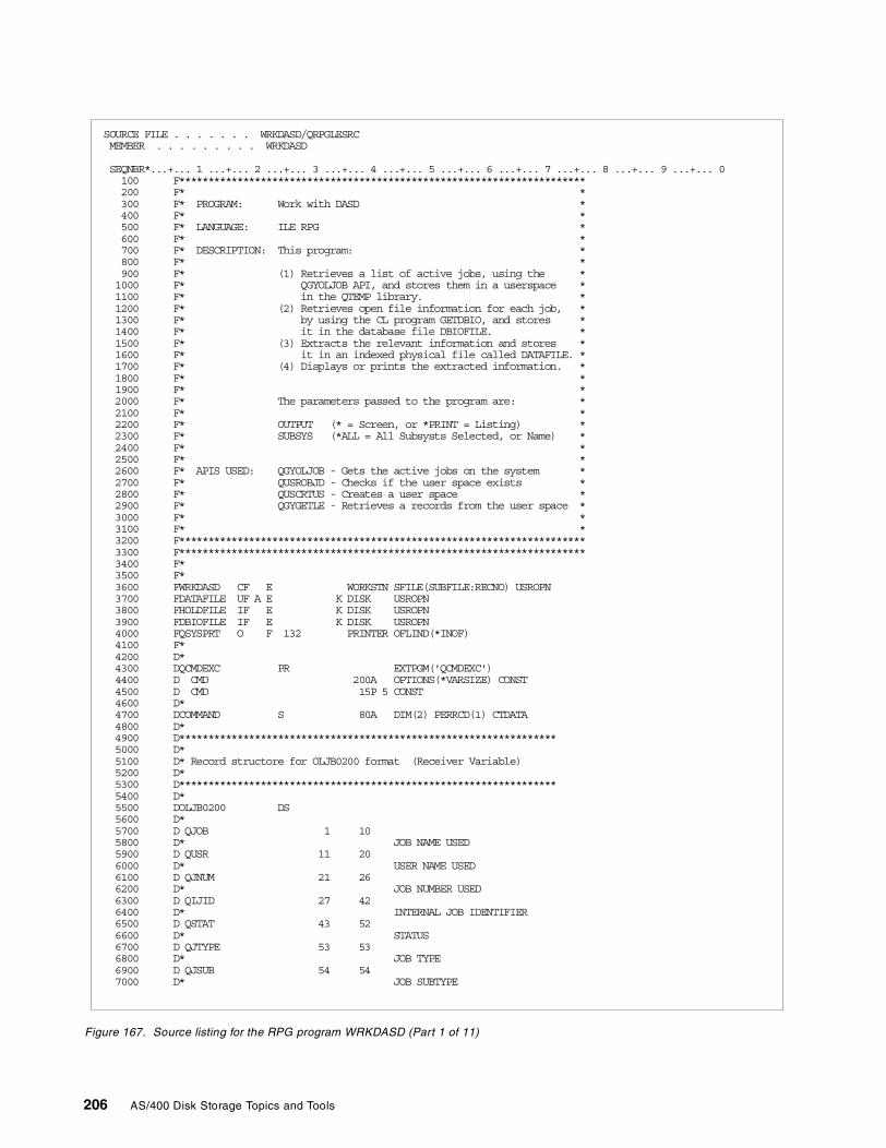
Figure 167. Source listing for the RPG program WRKDASD (Part 1 of 11)
SOURCE FILE . . . . . . . WRKDASD/QRPGLESRCMEMBER . . . . . . . . . WRKDASD
SEQNBR*...+... 1 ...+... 2 ...+... 3 ...+... 4 ...+... 5 ...+... 6 ...+... 7 ...+... 8 ...+... 9 ...+... 0100 F**********************************************************************200 F* *300 F* PROGRAM: Work with DASD *400 F* *500 F* LANGUAGE: ILE RPG *600 F* *700 F* DESCRIPTION: This program: *800 F* *900 F* (1) Retrieves a list of active jobs, using the *1000 F* QGYOLJOB API, and stores them in a userspace *1100 F* in the QTEMP library. *1200 F* (2) Retrieves open file information for each job, *1300 F* by using the CL program GETDBIO, and stores *1400 F* it in the database file DBIOFILE. *1500 F* (3) Extracts the relevant information and stores *1600 F* it in an indexed physical file called DATAFILE. *1700 F* (4) Displays or prints the extracted information. *1800 F* *1900 F* *2000 F* The parameters passed to the program are: *2100 F* *2200 F* OUTPUT (* = Screen, or *PRINT = Listing) *2300 F* SUBSYS (*ALL = All Subsysts Selected, or Name) *2400 F* *2500 F* *2600 F* APIS USED: QGYOLJOB - Gets the active jobs on the system *2700 F* QUSROBJD - Checks if the user space exists *2800 F* QUSCRTUS - Creates a user space *2900 F* QGYGETLE - Retrieves a records from the user space *3000 F* *3100 F* *3200 F**********************************************************************3300 F**********************************************************************3400 F*3500 F*3600 FWRKDASD CF E WORKSTN SFILE(SUBFILE:RECNO) USROPN3700 FDATAFILE UF A E K DISK USROPN3800 FHOLDFILE IF E K DISK USROPN3900 FDBIOFILE IF E K DISK USROPN4000 FQSYSPRT O F 132 PRINTER OFLIND(*INOF)4100 F*4200 D*4300 DQCMDEXC PR EXTPGM('QCMDEXC')4400 D CMD 200A OPTIONS(*VARSIZE) CONST4500 D CMD 15P 5 CONST4600 D*4700 DCOMMAND S 80A DIM(2) PERRCD(1) CTDATA4800 D*4900 D*****************************************************************5000 D*5100 D* Record structore for OLJB0200 format (Receiver Variable)5200 D*5300 D*****************************************************************5400 D*5500 DOLJB0200 DS5600 D*5700 D QJOB 1 105800 D* JOB NAME USED5900 D QUSR 11 206000 D* USER NAME USED6100 D QJNUM 21 266200 D* JOB NUMBER USED6300 D QIJID 27 426400 D* INTERNAL JOB IDENTIFIER6500 D QSTAT 43 526600 D* STATUS6700 D QJTYPE 53 536800 D* JOB TYPE6900 D QJSUB 54 547000 D* JOB SUBTYPE
206 AS/400 Disk Storage Topics and Tools
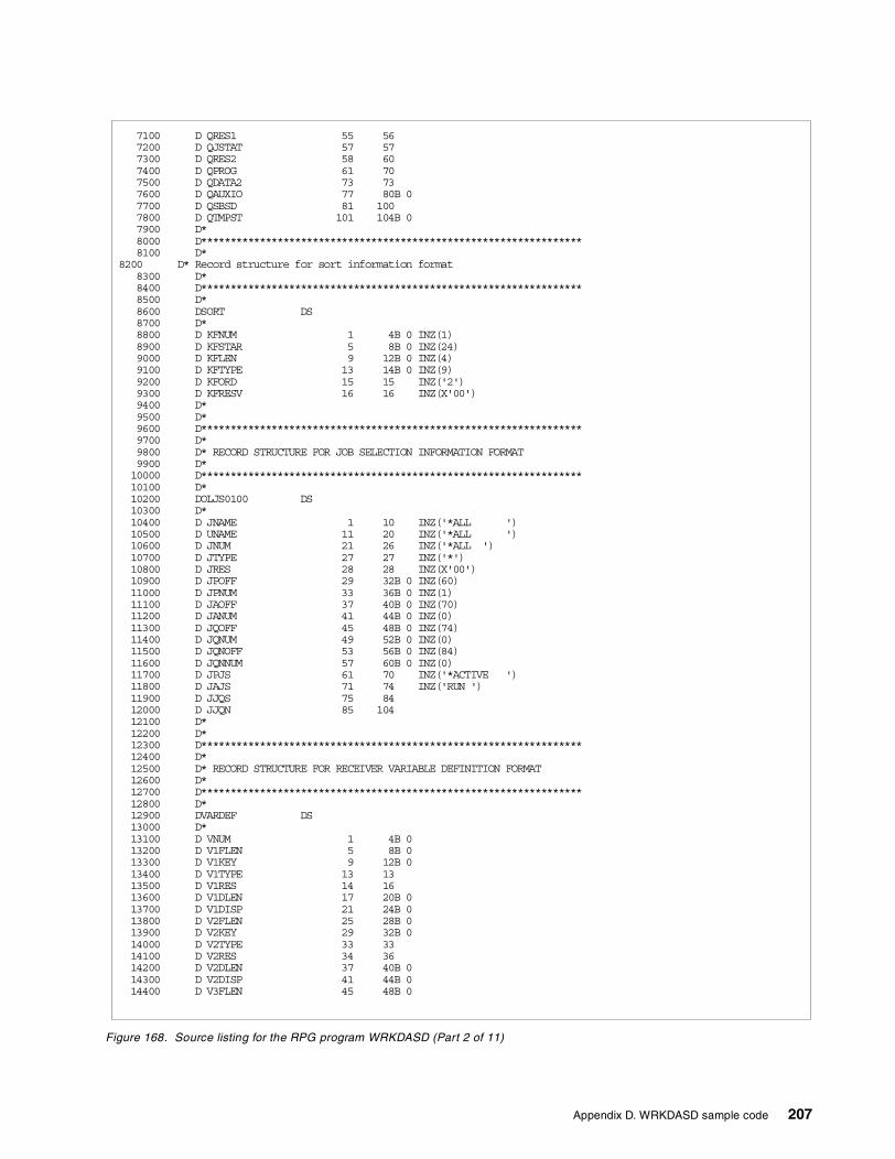
Figure 168. Source listing for the RPG program WRKDASD (Part 2 of 11)
7100 D QRES1 55 567200 D QJSTAT 57 577300 D QRES2 58 607400 D QPROG 61 707500 D QDATA2 73 737600 D QAUXIO 77 80B 07700 D QSBSD 81 1007800 D QTMPST 101 104B 07900 D*8000 D*****************************************************************8100 D*
8200 xxxxxD* Record structure for sort information format8300 D*8400 D*****************************************************************8500 D*8600 DSORT DS8700 D*8800 D KFNUM 1 4B 0 INZ(1)8900 D KFSTAR 5 8B 0 INZ(24)9000 D KFLEN 9 12B 0 INZ(4)9100 D KFTYPE 13 14B 0 INZ(9)9200 D KFORD 15 15 INZ('2')9300 D KFRESV 16 16 INZ(X'00')9400 D*9500 D*9600 D*****************************************************************9700 D*9800 D* RECORD STRUCTURE FOR JOB SELECTION INFORMATION FORMAT9900 D*10000 D*****************************************************************10100 D*10200 DOLJS0100 DS10300 D*10400 D JNAME 1 10 INZ('*ALL ')10500 D UNAME 11 20 INZ('*ALL ')10600 D JNUM 21 26 INZ('*ALL ')10700 D JTYPE 27 27 INZ('*')10800 D JRES 28 28 INZ(X'00')10900 D JPOFF 29 32B 0 INZ(60)11000 D JPNUM 33 36B 0 INZ(1)11100 D JAOFF 37 40B 0 INZ(70)11200 D JANUM 41 44B 0 INZ(0)11300 D JQOFF 45 48B 0 INZ(74)11400 D JQNUM 49 52B 0 INZ(0)11500 D JQNOFF 53 56B 0 INZ(84)11600 D JQNNUM 57 60B 0 INZ(0)11700 D JPJS 61 70 INZ('*ACTIVE ')11800 D JAJS 71 74 INZ('RUN ')11900 D JJQS 75 8412000 D JJQN 85 10412100 D*12200 D*12300 D*****************************************************************12400 D*12500 D* RECORD STRUCTURE FOR RECEIVER VARIABLE DEFINITION FORMAT12600 D*12700 D*****************************************************************12800 D*12900 DVARDEF DS13000 D*13100 D VNUM 1 4B 013200 D V1FLEN 5 8B 013300 D V1KEY 9 12B 013400 D V1TYPE 13 1313500 D V1RES 14 1613600 D V1DLEN 17 20B 013700 D V1DISP 21 24B 013800 D V2FLEN 25 28B 013900 D V2KEY 29 32B 014000 D V2TYPE 33 3314100 D V2RES 34 3614200 D V2DLEN 37 40B 014300 D V2DISP 41 44B 014400 D V3FLEN 45 48B 0
Appendix D. WRKDASD sample code 207
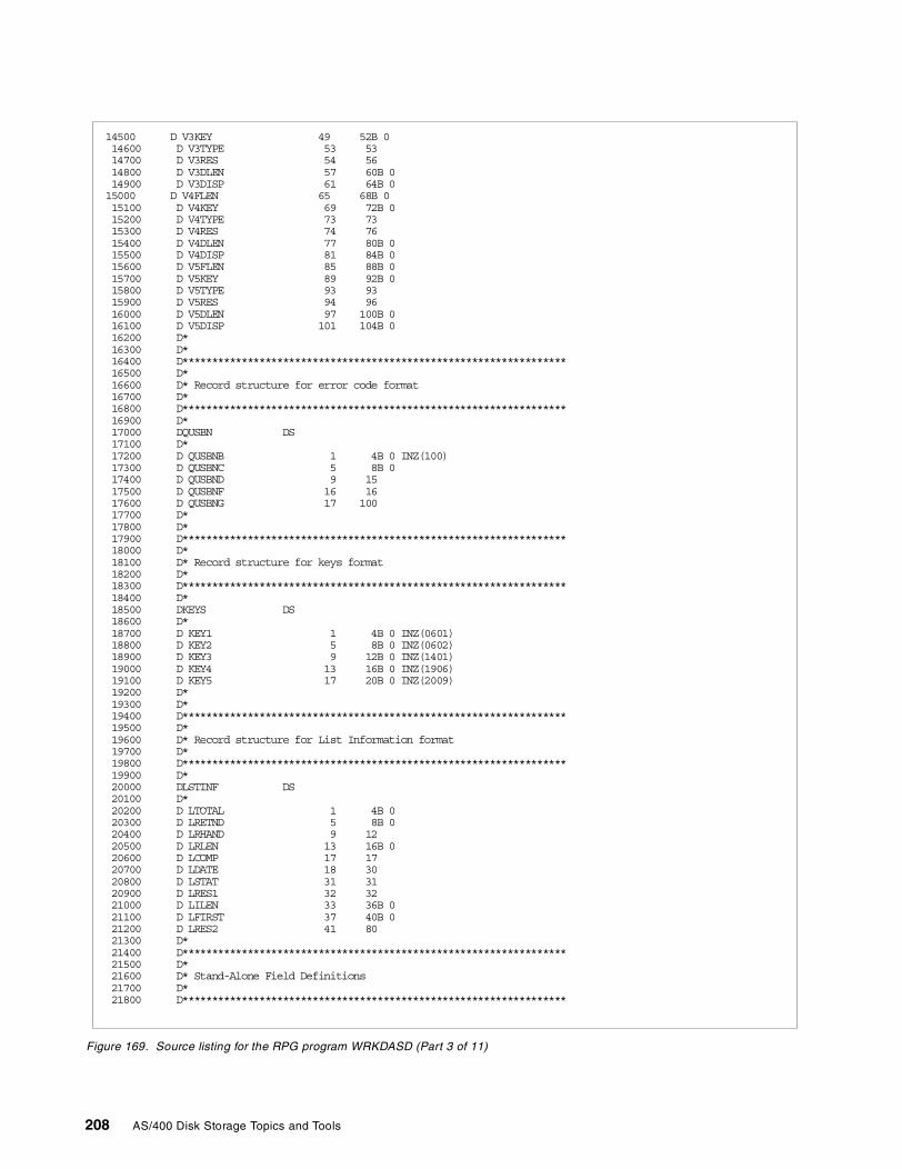
Figure 169. Source listing for the RPG program WRKDASD (Part 3 of 11)
14500 D V3KEY 49 52B 014600 D V3TYPE 53 5314700 D V3RES 54 5614800 D V3DLEN 57 60B 014900 D V3DISP 61 64B 015000 D V4FLEN 65 68B 015100 D V4KEY 69 72B 015200 D V4TYPE 73 7315300 D V4RES 74 7615400 D V4DLEN 77 80B 015500 D V4DISP 81 84B 015600 D V5FLEN 85 88B 015700 D V5KEY 89 92B 015800 D V5TYPE 93 9315900 D V5RES 94 9616000 D V5DLEN 97 100B 016100 D V5DISP 101 104B 016200 D*16300 D*16400 D*****************************************************************16500 D*16600 D* Record structure for error code format16700 D*16800 D*****************************************************************16900 D*17000 DQUSBN DS17100 D*17200 D QUSBNB 1 4B 0 INZ(100)17300 D QUSBNC 5 8B 017400 D QUSBND 9 1517500 D QUSBNF 16 1617600 D QUSBNG 17 10017700 D*17800 D*17900 D*****************************************************************18000 D*18100 D* Record structure for keys format18200 D*18300 D*****************************************************************18400 D*18500 DKEYS DS18600 D*18700 D KEY1 1 4B 0 INZ(0601)18800 D KEY2 5 8B 0 INZ(0602)18900 D KEY3 9 12B 0 INZ(1401)19000 D KEY4 13 16B 0 INZ(1906)19100 D KEY5 17 20B 0 INZ(2009)19200 D*19300 D*19400 D*****************************************************************19500 D*19600 D* Record structure for List Information format19700 D*19800 D*****************************************************************19900 D*20000 DLSTINF DS20100 D*20200 D LTOTAL 1 4B 020300 D LRETND 5 8B 020400 D LRHAND 9 1220500 D LRLEN 13 16B 020600 D LCOMP 17 1720700 D LDATE 18 3020800 D LSTAT 31 3120900 D LRES1 32 3221000 D LILEN 33 36B 021100 D LFIRST 37 40B 021200 D LRES2 41 8021300 D*21400 D*****************************************************************21500 D*21600 D* Stand-Alone Field Definitions21700 D*21800 D*****************************************************************
208 AS/400 Disk Storage Topics and Tools
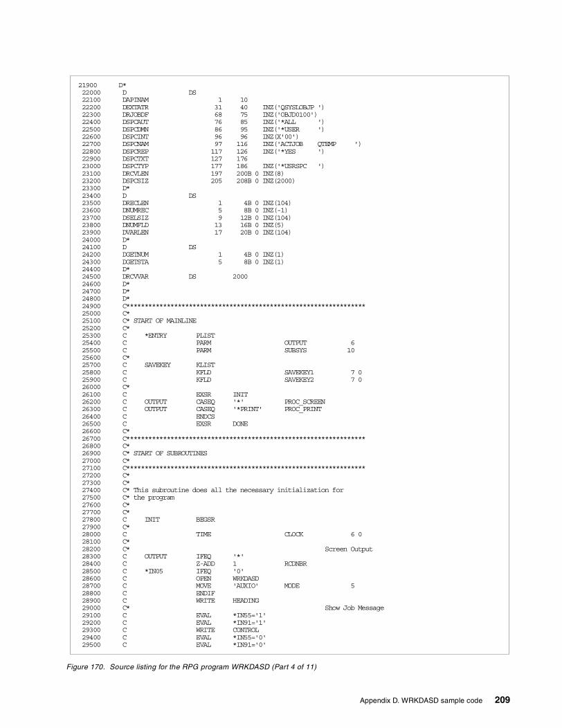
Figure 170. Source listing for the RPG program WRKDASD (Part 4 of 11)
21900 D*22000 D DS22100 DAPINAM 1 1022200 DEXTATR 31 40 INZ('QSYSLOBJP ')22300 DRJOBDF 68 75 INZ('OBJD0100')22400 DSPCAUT 76 85 INZ('*ALL ')22500 DSPCDMN 86 95 INZ('*USER ')22600 DSPCINT 96 96 INZ(X'00')22700 DSPCNAM 97 116 INZ('ACTJOB QTEMP ')22800 DSPCREP 117 126 INZ('*YES ')22900 DSPCTXT 127 17623000 DSPCTYP 177 186 INZ('*USRSPC ')23100 DRCVLEN 197 200B 0 INZ(8)23200 DSPCSIZ 205 208B 0 INZ(2000)23300 D*23400 D DS23500 DRECLEN 1 4B 0 INZ(104)23600 DNUMREC 5 8B 0 INZ(-1)23700 DSELSIZ 9 12B 0 INZ(104)23800 DNUMFLD 13 16B 0 INZ(5)23900 DVARLEN 17 20B 0 INZ(104)24000 D*24100 D DS24200 DGETNUM 1 4B 0 INZ(1)24300 DGETSTA 5 8B 0 INZ(1)24400 D*24500 DRCVVAR DS 200024600 D*24700 D*24800 D*24900 C*****************************************************************25000 C*25100 C* START OF MAINLINE25200 C*25300 C *ENTRY PLIST25400 C PARM OUTPUT 625500 C PARM SUBSYS 1025600 C*25700 C SAVEKEY KLIST25800 C KFLD SAVEKEY1 7 025900 C KFLD SAVEKEY2 7 026000 C*26100 C EXSR INIT26200 C OUTPUT CASEQ '*' PROC_SCREEN26300 C OUTPUT CASEQ '*PRINT' PROC_PRINT26400 C ENDCS26500 C EXSR DONE26600 C*26700 C*****************************************************************26800 C*26900 C* START OF SUBROUTINES27000 C*27100 C*****************************************************************27200 C*27300 C*27400 C* This subroutine does all the necessary initialization for27500 C* the program27600 C*27700 C*27800 C INIT BEGSR27900 C*28000 C TIME CLOCK 6 028100 C*28200 C* Screen Output28300 C OUTPUT IFEQ '*'28400 C Z-ADD 1 RCDNBR28500 C *IN05 IFEQ '0'28600 C OPEN WRKDASD28700 C MOVE 'AUXIO' MODE 528800 C ENDIF28900 C WRITE HEADING29000 C* Show Job Message29100 C EVAL *IN55='1'29200 C EVAL *IN91='1'29300 C WRITE CONTROL29400 C EVAL *IN55='0'29500 C EVAL *IN91='0'
Appendix D. WRKDASD sample code 209
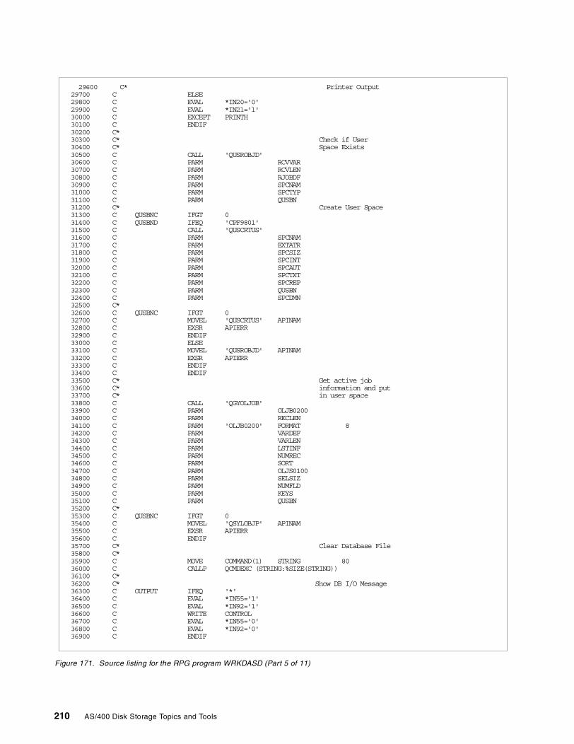
Figure 171. Source listing for the RPG program WRKDASD (Part 5 of 11)
29600 C* Printer Output29700 C ELSE29800 C EVAL *IN20='0'29900 C EVAL *IN21='1'30000 C EXCEPT PRINTH30100 C ENDIF30200 C*30300 C* Check if User30400 C* Space Exists30500 C CALL 'QUSROBJD'30600 C PARM RCVVAR30700 C PARM RCVLEN30800 C PARM RJOBDF30900 C PARM SPCNAM31000 C PARM SPCTYP31100 C PARM QUSBN31200 C* Create User Space31300 C QUSBNC IFGT 031400 C QUSBND IFEQ 'CPF9801'31500 C CALL 'QUSCRTUS'31600 C PARM SPCNAM31700 C PARM EXTATR31800 C PARM SPCSIZ31900 C PARM SPCINT32000 C PARM SPCAUT32100 C PARM SPCTXT32200 C PARM SPCREP32300 C PARM QUSBN32400 C PARM SPCDMN32500 C*32600 C QUSBNC IFGT 032700 C MOVEL 'QUSCRTUS' APINAM32800 C EXSR APIERR32900 C ENDIF33000 C ELSE33100 C MOVEL 'QUSROBJD' APINAM33200 C EXSR APIERR33300 C ENDIF33400 C ENDIF33500 C* Get active job33600 C* information and put33700 C* in user space33800 C CALL 'QGYOLJOB'33900 C PARM OLJB020034000 C PARM RECLEN34100 C PARM 'OLJB0200' FORMAT 834200 C PARM VARDEF34300 C PARM VARLEN34400 C PARM LSTINF34500 C PARM NUMREC34600 C PARM SORT34700 C PARM OLJS010034800 C PARM SELSIZ34900 C PARM NUMFLD35000 C PARM KEYS35100 C PARM QUSBN35200 C*35300 C QUSBNC IFGT 035400 C MOVEL 'QSYLOBJP' APINAM35500 C EXSR APIERR35600 C ENDIF35700 C* Clear Database File35800 C*35900 C MOVE COMMAND(1) STRING 8036000 C CALLP QCMDEXC (STRING:%SIZE(STRING))36100 C*36200 C* Show DB I/O Message36300 C OUTPUT IFEQ '*'36400 C EVAL *IN55='1'36500 C EVAL *IN92='1'36600 C WRITE CONTROL36700 C EVAL *IN55='0'36800 C EVAL *IN92='0'36900 C ENDIF
210 AS/400 Disk Storage Topics and Tools
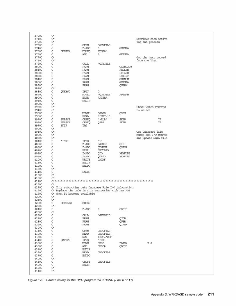
Figure 172. Source listing for the RPG program WRKDASD (Part 6 of 11)
37000 C*37100 C* Retrieve each active37200 C* job and process37300 C OPEN DATAFILE37400 C Z-ADD 0 GETSTA37500 C GETSTA DOUEQ LTOTAL37600 C ADD 1 GETSTA37700 C* Get the next record37800 C* from the list37900 C CALL 'QGYGTLE'38000 C PARM OLJB020038100 C PARM RECLEN38200 C PARM LRHAND38300 C PARM LSTINF38400 C PARM GETNUM38500 C PARM GETSTA38600 C PARM QUSBN38700 C*38800 C QUSBNC IFGT 038900 C MOVEL 'QGYGTLE' APINAM39000 C EXSR APIERR39100 C ENDIF39200 C*39300 C* Check which records39400 C* to select39500 C MOVEL QSBSD QSBS39600 C EVAL *IN77='0'39700 C SUBSYS CABEQ '*ALL' SKIP 7739800 C SUBSYS CABEQ QSBS SKIP 7739900 C SKIP TAG40000 C*40100 C* Get Database file40200 C* names and I/O counts40300 C* and update DATA file40400 C *IN77 IFEQ '1'40500 C Z-ADD QAUXIO QIO40600 C Z-ADD QTMPST QSTOR40700 C EXSR GETDBIO40800 C Z-ADD QIO KEYFLD140900 C Z-ADD QDBIO KEYFLD241000 C WRITE DATAF41100 C ENDIF41200 C ENDDO41300 C*41400 C ENDSR41500 C*41600 C*41700 C*****************************************************************41800 C*41900 C* This subroutine gets Database File I/O information
xx41900 C* Replace the code in this subroutime with new APIxx41900 C* when it becomes availablex 42000 C*42100 C*42200 C GETDBIO BEGSR42300 C*42400 C Z-ADD 0 QDBIO42500 C*42600 C CALL 'GETDBIO'42700 C PARM QJOB42800 C PARM QUSR42900 C PARM QJNUM43000 C*43100 C OPEN DBIOFILE43200 C READ DBIOFILE43300 C DOW %EOF=*OFF43400 C DBTYPE IFEQ 'PHY'43500 C MOVE DBIO DBIO# 7 043600 C ADD DBIO# QDBIO43700 C ENDIF43800 C READ DBIOFILE43900 C ENDDO44000 C*44100 C CLOSE DBIOFILE44200 C ENDSR44300 C*44400 C*
Appendix D. WRKDASD sample code 211
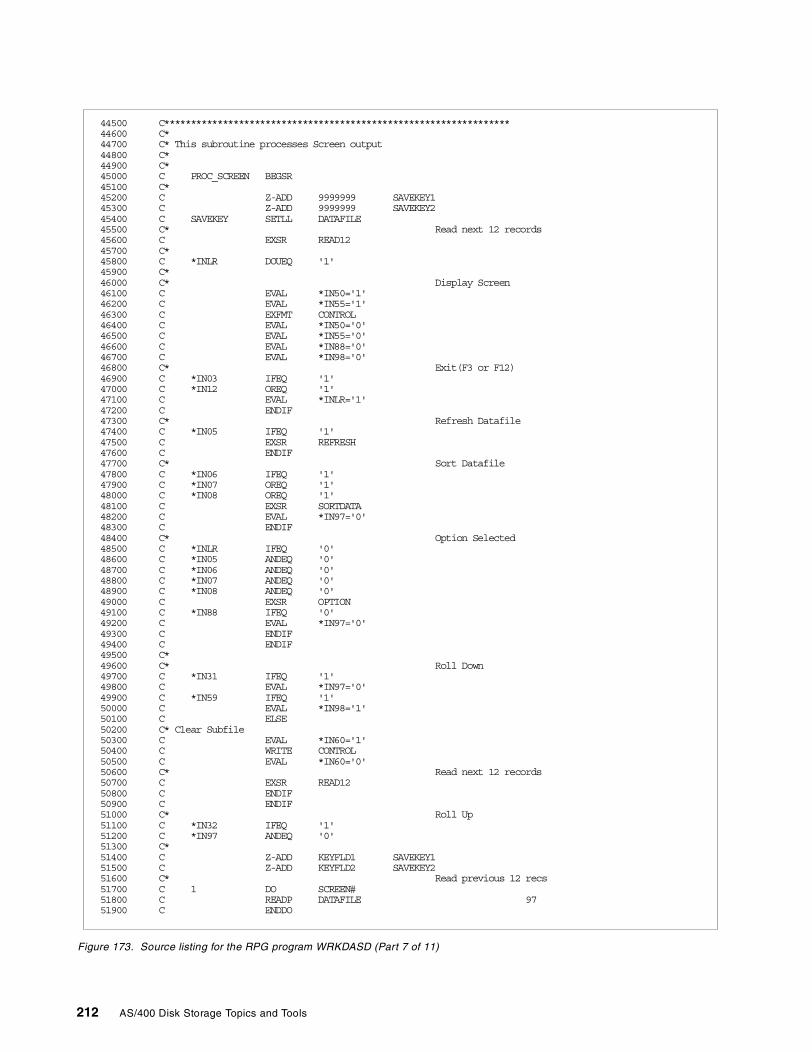
Figure 173. Source listing for the RPG program WRKDASD (Part 7 of 11)
44500 C*****************************************************************44600 C*44700 C* This subroutine processes Screen output44800 C*44900 C*45000 C PROC_SCREEN BEGSR45100 C*45200 C Z-ADD 9999999 SAVEKEY145300 C Z-ADD 9999999 SAVEKEY245400 C SAVEKEY SETLL DATAFILE45500 C* Read next 12 records45600 C EXSR READ1245700 C*45800 C *INLR DOUEQ '1'45900 C*46000 C* Display Screen46100 C EVAL *IN50='1'46200 C EVAL *IN55='1'46300 C EXFMT CONTROL46400 C EVAL *IN50='0'46500 C EVAL *IN55='0'46600 C EVAL *IN88='0'46700 C EVAL *IN98='0'46800 C* Exit(F3 or F12)46900 C *IN03 IFEQ '1'47000 C *IN12 OREQ '1'47100 C EVAL *INLR='1'47200 C ENDIF47300 C* Refresh Datafile47400 C *IN05 IFEQ '1'47500 C EXSR REFRESH47600 C ENDIF47700 C* Sort Datafile47800 C *IN06 IFEQ '1'47900 C *IN07 OREQ '1'48000 C *IN08 OREQ '1'48100 C EXSR SORTDATA48200 C EVAL *IN97='0'48300 C ENDIF48400 C* Option Selected48500 C *INLR IFEQ '0'48600 C *IN05 ANDEQ '0'48700 C *IN06 ANDEQ '0'48800 C *IN07 ANDEQ '0'48900 C *IN08 ANDEQ '0'49000 C EXSR OPTION49100 C *IN88 IFEQ '0'49200 C EVAL *IN97='0'49300 C ENDIF49400 C ENDIF49500 C*49600 C* Roll Down49700 C *IN31 IFEQ '1'49800 C EVAL *IN97='0'49900 C *IN59 IFEQ '1'50000 C EVAL *IN98='1'50100 C ELSE50200 C* Clear Subfile50300 C EVAL *IN60='1'50400 C WRITE CONTROL50500 C EVAL *IN60='0'50600 C* Read next 12 records50700 C EXSR READ1250800 C ENDIF50900 C ENDIF51000 C* Roll Up51100 C *IN32 IFEQ '1'51200 C *IN97 ANDEQ '0'51300 C*51400 C Z-ADD KEYFLD1 SAVEKEY151500 C Z-ADD KEYFLD2 SAVEKEY251600 C* Read previous 12 recs51700 C 1 DO SCREEN#51800 C READP DATAFILE 9751900 C ENDDO
212 AS/400 Disk Storage Topics and Tools
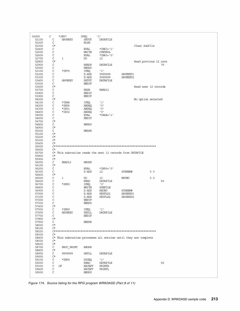
Figure 174. Source listing for the RPG program WRKDASD (Part 8 of 11)
52000 C *IN97 IFEQ '1'52100 C SAVEKEY SETGT DATAFILE52200 C ELSE52300 C* Clear Subfile52400 C EVAL *IN60='1'52500 C WRITE CONTROL52600 C EVAL *IN60='0'52700 C 1 DO 1252800 C* Read previous 12 recs52900 C READP DATAFILE 7953000 C ENDDO53100 C *IN79 IFEQ '1'53200 C Z-ADD 9999999 SAVEKEY153300 C Z-ADD 9999999 SAVEKEY253400 C SAVEKEY SETGT DATAFILE53500 C ENDIF53600 C* Read next 12 records53700 C EXSR READ1253800 C ENDIF53900 C ENDIF54000 C* No option selected54100 C *IN88 IFEQ '1'54200 C *IN05 ANDEQ '0'54300 C *IN31 ANDEQ '0'54400 C *IN32 ANDEQ '0'54500 C EVAL *INLR='1'54600 C ENDIF54700 C*54800 C ENDDO54900 C*55000 C ENDSR55100 C*55200 C*55300 C*55400 C*55500 C*****************************************************************55600 C*55700 C* This subroutine reads the next 12 records from DATAFILE55800 C*55900 C*56000 C READ12 BEGSR56100 C*56200 C EVAL *IN59='0'56300 C Z-ADD 12 SCREEN# 5 056400 C*56500 C 1 DO 12 RECNO 5 056600 C READ DATAFILE 5956700 C *IN59 IFEQ '0'56800 C WRITE SUBFILE56900 C Z-ADD RECNO SCREEN#57000 C Z-ADD KEYFLD1 SAVEKEY157100 C Z-ADD KEYFLD2 SAVEKEY257200 C ENDIF57300 C ENDDO57400 C*57500 C *IN59 IFEQ '1'57600 C SAVEKEY SETLL DATAFILE57700 C ENDIF57800 C*57900 C ENDSR58000 C*58100 C*58200 C*****************************************************************58300 C*58400 C* This subroutine processes all entries until they are complete58500 C*58600 C*58700 C PROC_PRINT BEGSR58800 C*58900 C 9999999 SETLL DATAFILE59000 C*59100 C *IN59 DOUEQ '1'59200 C READ DATAFILE 5959300 C OF EXCEPT PRINTH59400 C EXCEPT PRINTL59500 C ENDDO
Appendix D. WRKDASD sample code 213
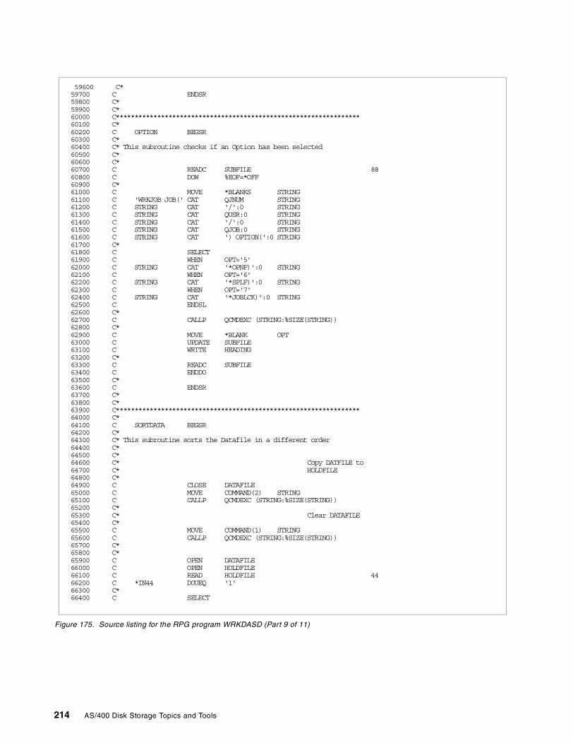
Figure 175. Source listing for the RPG program WRKDASD (Part 9 of 11)
59600 C*59700 C ENDSR59800 C*59900 C*60000 C*****************************************************************60100 C*60200 C OPTION BEGSR60300 C*60400 C* This subroutine checks if an Option has been selected60500 C*60600 C*60700 C READC SUBFILE 8860800 C DOW %EOF=*OFF60900 C*61000 C MOVE *BLANKS STRING61100 C 'WRKJOB JOB(' CAT QJNUM STRING61200 C STRING CAT '/':0 STRING61300 C STRING CAT QUSR:0 STRING61400 C STRING CAT '/':0 STRING61500 C STRING CAT QJOB:0 STRING61600 C STRING CAT ') OPTION(':0 STRING61700 C*61800 C SELECT61900 C WHEN OPT='5'62000 C STRING CAT '*OPNF)':0 STRING62100 C WHEN OPT='6'62200 C STRING CAT '*SPLF)':0 STRING62300 C WHEN OPT='7'62400 C STRING CAT '*JOBLCK)':0 STRING62500 C ENDSL62600 C*62700 C CALLP QCMDEXC (STRING:%SIZE(STRING))62800 C*62900 C MOVE *BLANK OPT63000 C UPDATE SUBFILE63100 C WRITE HEADING63200 C*63300 C READC SUBFILE63400 C ENDDO63500 C*63600 C ENDSR63700 C*63800 C*63900 C*****************************************************************64000 C*64100 C SORTDATA BEGSR64200 C*64300 C* This subroutine sorts the Datafile in a different order64400 C*64500 C*64600 C* Copy DATFILE to64700 C* HOLDFILE64800 C*64900 C CLOSE DATAFILE65000 C MOVE COMMAND(2) STRING65100 C CALLP QCMDEXC (STRING:%SIZE(STRING))65200 C*65300 C* Clear DATAFILE65400 C*65500 C MOVE COMMAND(1) STRING65600 C CALLP QCMDEXC (STRING:%SIZE(STRING))65700 C*65800 C*65900 C OPEN DATAFILE66000 C OPEN HOLDFILE66100 C READ HOLDFILE 4466200 C *IN44 DOUEQ '1'66300 C*66400 C SELECT
214 AS/400 Disk Storage Topics and Tools
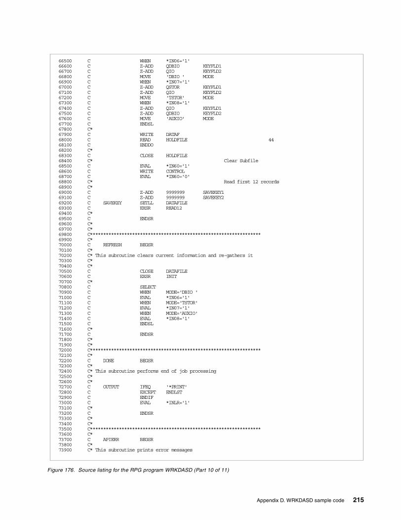
Figure 176. Source listing for the RPG program WRKDASD (Part 10 of 11)
66500 C WHEN *IN06='1'66600 C Z-ADD QDBIO KEYFLD166700 C Z-ADD QIO KEYFLD266800 C MOVE 'DBIO ' MODE66900 C WHEN *IN07='1'67000 C Z-ADD QSTOR KEYFLD167100 C Z-ADD QIO KEYFLD267200 C MOVE 'TSTOR' MODE67300 C WHEN *IN08='1'67400 C Z-ADD QIO KEYFLD167500 C Z-ADD QDBIO KEYFLD267600 C MOVE 'AUXIO' MODE67700 C ENDSL67800 C*67900 C WRITE DATAF68000 C READ HOLDFILE 4468100 C ENDDO68200 C*68300 C CLOSE HOLDFILE68400 C* Clear Subfile68500 C EVAL *IN60='1'68600 C WRITE CONTROL68700 C EVAL *IN60='0'68800 C* Read first 12 records68900 C*69000 C Z-ADD 9999999 SAVEKEY169100 C Z-ADD 9999999 SAVEKEY269200 C SAVEKEY SETLL DATAFILE69300 C EXSR READ1269400 C*69500 C ENDSR69600 C*69700 C*69800 C*****************************************************************69900 C*70000 C REFRESH BEGSR70100 C*70200 C* This subroutine clears current information and re-gathers it70300 C*70400 C*70500 C CLOSE DATAFILE70600 C EXSR INIT70700 C*70800 C SELECT70900 C WHEN MODE='DBIO '71000 C EVAL *IN06='1'71100 C WHEN MODE='TSTOR'71200 C EVAL *IN07='1'71300 C WHEN MODE='AUXIO'71400 C EVAL *IN08='1'71500 C ENDSL71600 C*71700 C ENDSR71800 C*71900 C*72000 C*****************************************************************72100 C*72200 C DONE BEGSR72300 C*72400 C* This subroutine performs end of job processing72500 C*72600 C*72700 C OUTPUT IFEQ '*PRINT'72800 C EXCEPT ENDLST72900 C ENDIF73000 C EVAL *INLR='1'73100 C*73200 C ENDSR73300 C*73400 C*73500 C*****************************************************************73600 C*73700 C APIERR BEGSR73800 C*73900 C* This subroutine prints error messages
Appendix D. WRKDASD sample code 215
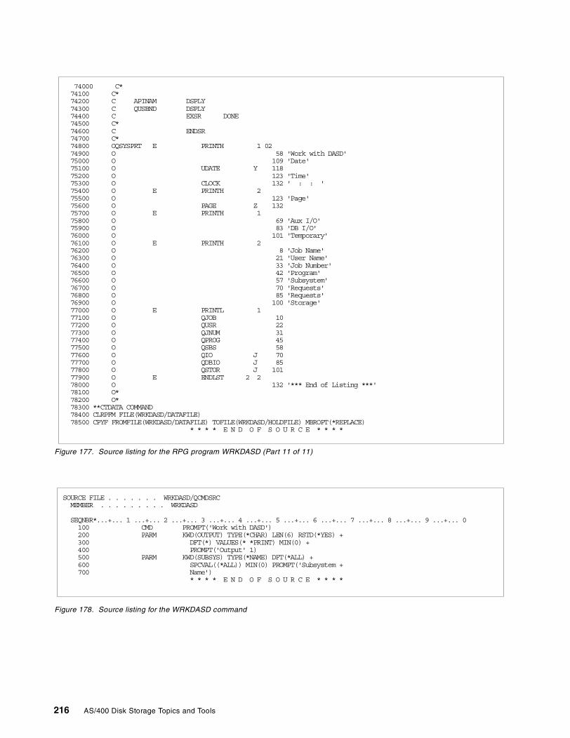
Figure 177. Source listing for the RPG program WRKDASD (Part 11 of 11)
Figure 178. Source listing for the WRKDASD command
74000 C*74100 C*74200 C APINAM DSPLY74300 C QUSBND DSPLY74400 C EXSR DONE74500 C*74600 C ENDSR74700 C*74800 OQSYSPRT E PRINTH 1 0274900 O 58 'Work with DASD'75000 O 109 'Date'75100 O UDATE Y 11875200 O 123 'Time'75300 O CLOCK 132 ' : : '75400 O E PRINTH 275500 O 123 'Page'75600 O PAGE Z 13275700 O E PRINTH 175800 O 69 'Aux I/O'75900 O 83 'DB I/O'76000 O 101 'Temporary'76100 O E PRINTH 276200 O 8 'Job Name'76300 O 21 'User Name'76400 O 33 'Job Number'76500 O 42 'Program'76600 O 57 'Subsystem'76700 O 70 'Requests'76800 O 85 'Requests'76900 O 100 'Storage'77000 O E PRINTL 177100 O QJOB 1077200 O QUSR 2277300 O QJNUM 3177400 O QPROG 4577500 O QSBS 5877600 O QIO J 7077700 O QDBIO J 8577800 O QSTOR J 10177900 O E ENDLST 2 278000 O 132 '*** End of Listing ***'78100 O*78200 O*78300 **CTDATA COMMAND78400 CLRPFM FILE(WRKDASD/DATAFILE)78500 CPYF FROMFILE(WRKDASD/DATAFILE) TOFILE(WRKDASD/HOLDFILE) MBROPT(*REPLACE)
* * * * E N D O F S O U R C E * * * *
SOURCE FILE . . . . . . . WRKDASD/QCMDSRCMEMBER . . . . . . . . . WRKDASD
SEQNBR*...+... 1 ...+... 2 ...+... 3 ...+... 4 ...+... 5 ...+... 6 ...+... 7 ...+... 8 ...+... 9 ...+... 0100 CMD PROMPT('Work with DASD')200 PARM KWD(OUTPUT) TYPE(*CHAR) LEN(6) RSTD(*YES) +300 DFT(*) VALUES(* *PRINT) MIN(0) +400 PROMPT('Output' 1)500 PARM KWD(SUBSYS) TYPE(*NAME) DFT(*ALL) +600 SPCVAL((*ALL)) MIN(0) PROMPT('Subsystem +700 Name')
* * * * E N D O F S O U R C E * * * *
216 AS/400 Disk Storage Topics and Tools
Appendix E. Using the additional material
This redbook also contains additional material that is available for downloading from theWeb. See the appropriate section below for instructions on using or downloading eachtype of material.
E.1 Locating the additional material on the Internet
The Web material associated with this redbook is also available in softcopy on theInternet from the IBM Redbooks Web server. The code is available in a save file that canbe downloaded from the redbooks site. Point your Web browser to:
ftp://www.redbooks.ibm.com/redbooks/SG24-5693
Alternatively, you can go to the IBM Redbooks Web site at:
http://www.redbooks.ibm.com/
Select Additional materials, and open the directory that corresponds with the redbookform number.
E.2 Using the Web material
The materials included in the additional materials section of the site are provided “as is”.That means, there is no support available for them.
Go to the ITSO Web site at: http://www.redbooks.ibm.com
Select the Additional Materials tab. Scroll down the page until you find the SG245693directory. Review the readme.txt file for information about how to get the additionalmaterials to your system.
The additional Web material that accompanies this redbook includes:
File name DescriptionSG245693.zip Zipped code samples5693readme.txt Text document describing how to obtain and load code to
customer’s AS/400 system
© Copyright IBM Corp. 2000 217

218 AS/400 Disk Storage Topics and Tools
Appendix F. Special notices
This publication is intended to help AS/400 system administrators and operatorsunderstand and manage the disk storage subsystem of their AS/400 system. Theinformation in this publication is not intended as the specification of anyprogramming interface provided by OS/400 operating system. See thePUBLICATIONS section of the IBM Programming Announcement for OS/400operating system and AS/400 Performance Tools products for more informationabout what publications are considered to be product documentation.
References in this publication to IBM products, programs or services do not implythat IBM intends to make these available in all countries in which IBM operates.Any reference to an IBM product, program, or service is not intended to state orimply that only IBM's product, program, or service may be used. Any functionallyequivalent program that does not infringe any of IBM's intellectual property rightsmay be used instead of the IBM product, program or service.
Information in this book was developed in conjunction with use of the equipmentspecified, and is limited in application to those specific hardware and softwareproducts and levels.
IBM may have patents or pending patent applications covering subject matter inthis document. The furnishing of this document does not give you any license tothese patents. You can send license inquiries, in writing, to the IBM Director ofLicensing, IBM Corporation, North Castle Drive, Armonk, NY 10504-1785.
Licensees of this program who wish to have information about it for the purposeof enabling: (i) the exchange of information between independently createdprograms and other programs (including this one) and (ii) the mutual use of theinformation which has been exchanged, should contact IBM Corporation, Dept.600A, Mail Drop 1329, Somers, NY 10589 USA.
Such information may be available, subject to appropriate terms and conditions,including in some cases, payment of a fee.
The information contained in this document has not been submitted to any formalIBM test and is distributed AS IS. The information about non-IBM ("vendor")products in this manual has been supplied by the vendor and IBM assumes noresponsibility for its accuracy or completeness. The use of this information or theimplementation of any of these techniques is a customer responsibility anddepends on the customer's ability to evaluate and integrate them into thecustomer's operational environment. While each item may have been reviewedby IBM for accuracy in a specific situation, there is no guarantee that the same orsimilar results will be obtained elsewhere. Customers attempting to adapt thesetechniques to their own environments do so at their own risk.
Any pointers in this publication to external Web sites are provided forconvenience only and do not in any manner serve as an endorsement of theseWeb sites.
Any performance data contained in this document was determined in a controlledenvironment, and therefore, the results that may be obtained in other operatingenvironments may vary significantly. Users of this document should verify theapplicable data for their specific environment.
© Copyright IBM Corp. 2000 219
This document contains examples of data and reports used in daily businessoperations. To illustrate them as completely as possible, the examples containthe names of individuals, companies, brands, and products. All of these namesare fictitious and any similarity to the names and addresses used by an actualbusiness enterprise is entirely coincidental.
Reference to PTF numbers that have not been released through the normaldistribution process does not imply general availability. The purpose of includingthese reference numbers is to alert IBM customers to specific information relativeto the implementation of the PTF when it becomes available to each customeraccording to the normal IBM PTF distribution process.
The following terms are trademarks of the International Business MachinesCorporation in the United States and/or other countries:
The following terms are trademarks of other companies:
Tivoli, Manage. Anything. Anywhere.,The Power To Manage., Anything.Anywhere.,TME, NetView, Cross-Site, Tivoli Ready, Tivoli Certified, Planet Tivoli,and Tivoli Enterprise are trademarks or registered trademarks of Tivoli SystemsInc., an IBM company, in the United States, other countries, or both. In Denmark,Tivoli is a trademark licensed from Kjøbenhavns Sommer - Tivoli A/S.
C-bus is a trademark of Corollary, Inc. in the United States and/or other countries.
Java and all Java-based trademarks and logos are trademarks or registeredtrademarks of Sun Microsystems, Inc. in the United States and/or other countries.
Microsoft, Windows, Windows NT, and the Windows logo are trademarks ofMicrosoft Corporation in the United States and/or other countries.
PC Direct is a trademark of Ziff Communications Company in the United Statesand/or other countries and is used by IBM Corporation under license.
ActionMedia, LANDesk, MMX, Pentium and ProShare are trademarks of IntelCorporation in the United States and/or other countries.
AFP AIXAS/400 ATCT DB2IBM ImagePlusInformation Warehouse NetfinityNetView OfficeVisionOfficeVision/400 OS/400RS/6000 S/390SP StorWatchSystem/36 System/38System/390 Versatile Storage ServerXT 30903890 400
220 AS/400 Disk Storage Topics and Tools
UNIX is a registered trademark in the United States and other countries licensedexclusively through The Open Group.
SET and the SET logo are trademarks owned by SET Secure ElectronicTransaction LLC.
Other company, product, and service names may be trademarks or service marksof others.
Appendix F. Special notices 221

222 AS/400 Disk Storage Topics and Tools
Appendix G. Related publications
The publications listed in this section are considered particularly suitable for amore detailed discussion of the topics covered in this redbook.
G.1 IBM RedbooksFor information on ordering these ITSO publications, see “How to get IBMRedbooks” on page 227.
• AS/400e System Handbook, GA19-5486
• AS/400 System Builder, SG24-2155
• The System Administrator’s Companion to AS/400 Availability and Recovery,SG24-2161
• IBM Versatile Storage Server, SG24-2221
• DB2/400 Advanced Database Functions, SG24-4249
• Using Tivoli Storage Management to Back Up Databases, SG24-4335
• Complementing AS/400 Storage Management Using Hierarchical StorageManagement APIs, SG24-4450
• Using ADSM to Back Up Lotus Domino, SG24-4534
• Using ADSM Hierarchical Storage Management, SG24-4631
• A Practical Approach to Managing Backup Recovery and Media Services forOS/400, SG24-4840
• DB2/400: Mastering Data Warehousing Functions, SG24-5184
• AS/400 Consolidation Strategies and Implementation, SG24-5186
• AS/400 Remote Journal Function for High Availability and Data Replication,SG24-5189
• AS/400 Client Access Express for Windows: Implementing V4R4M0,SG24-5191
• The AS/400 NetServer Advantage, SG24-5196
• SAP Business Information Warehouse on the AS/400 System, SG24-5200
• Management Central: A Smart Way to Manage AS/400 Systems, SG24-5407
• Slicing the AS/400 with Logical Partitioning: A How to Guide, SG24-5439
• Introduction to Storage Area Network, SAN, SG24-5470
The following publications are available in soft copy only from the redbooks Website: http://www.redbooks.ibm.com/
• Implementing IBM SAA ImagePlus WAF/400 File Cabinet and OpticalLibraries, GG24-4188
• IBM SAA ImagePlus Workfolder Application Facility/400 and Remote 3995Library, GG24-4413
• AS/400 Performance Explorer Tips and Techniques, SG24-4781
• Data Warehousing Solutions on the AS/400, SG24-4872
© Copyright IBM Corp. 2000 223
G.2 IBM Redbooks collections
Redbooks are also available on the following CD-ROMs. Click the CD-ROMsbutton at http://www.redbooks.ibm.com/ for information about all the CD-ROMsoffered, updates and formats.
G.3 Other resources
These publications are also relevant as further information sources:
• Performance Tools/400, SC41-4340
• AS/400 Job Scheduler, SC41-5300
• AS/400 Backup and Recovery, SC41-5304
• AS/400 Work Management Guide, SC41-5306
• Performance Tools for AS/400, SC41-5340
• Backup Recovery and Media Services/400, SC41-5345
• Hierarchical Storage Management Use, SC41-5351
• APPC Programming, SC41-5443
• AS/400 CL Reference, V4R4, SC41-5722
• System API Reference, SC41-5801
• 940x 170, 6xx, 7xx, and Sxx System Installation and Upgrade, SY44-5950
• Problem Analysis Guide, SY44-5955
The following publications are available in soft copy only by visiting the Web siteat: http://publib.boulder.ibm.com/pubs/html/as400/online/homeeng1.htm
• AS/400 Performance Capabilities Reference V4R4, SC41-0607
• AS/400 System Operation, SC41-4203
• AS/400 Database Programming, SC41-5701
• Integrated File System Introduction, SC41-5711
CD-ROM Title Collection KitNumber
System/390 Redbooks Collection SK2T-2177Networking and Systems Management Redbooks Collection SK2T-6022Transaction Processing and Data Management Redbooks Collection SK2T-8038Lotus Redbooks Collection SK2T-8039Tivoli Redbooks Collection SK2T-8044AS/400 Redbooks Collection SK2T-2849Netfinity Hardware and Software Redbooks Collection SK2T-8046RS/6000 Redbooks Collection (BkMgr Format) SK2T-8040RS/6000 Redbooks Collection (PDF Format) SK2T-8043Application Development Redbooks Collection SK2T-8037IBM Enterprise Storage and Systems Management Solutions SK3T-3694
224 AS/400 Disk Storage Topics and Tools
G.4 Referenced Web sites
These Web sites are also relevant as further information sources:
• AS/400 Beyond Technology Page: http://www.as400.ibm.com/beyondtech
• AS/400 Information Center: http://www.as400.ibm.com/infocenter
• AS/400 Technical Studio: http://www.as400.ibm.com/techstudio
• Hierarchical Storage Management information:http://www.as400.ibm.com/beyondtech/hsm.htm
• IBM Redbooks home page: http://www.redbooks.ibm.com
• AS/400 Information Center:http://publib.boulder.ibm.com/pubs/html/as400/v4r4/ic2924/info/INFOCENT.HTM
• LPAR information: http://www.as400.ibm.com/lpar/
• Information on clustering:
– http://www.as400.ibm.com/ha/sec2.htm
– http://www.as400.ibm.com/ha/sec23.htm
– http://www.as400.ibm.com/ha/sec24.htm
• IBM storage home page: http://www.storage.ibm.com
• Information on Storage Area Network (SAN):http://www.storage.ibm.com/ibmsan/index.htm
• The Storage Area Networks: Putting Data to Work for e-businesses whitepaper: http://www.storage.ibm.com/ibmsan/whitepaper/strategy.htm
• The Disk Arm Requirements and Version Performance Considerations whitepapers: http://www.ibm.com.as400/developer/performance
• Site Preparation and Physical Planning at the AS/400 Technical Studio site at:http://www.as400.ibm.com/tstudio/planning/plngstrt.htm
• Additional information on optical library solutions:http://www.storage.ibm.com/hardsoft/opticalstor/index.html
• Magnetic Media Controllers information:http://www.as400.ibm.com/handbook/5486MagC.html
• Extended Adaptive Cache information:http://www.as400.ibm.com/beyondtech/ext_adapt_cache.htm
• PEX information: http://www.as400service.ibm.com/p_dir/pexgui.nsf
• AS/400 Online Library:http://publib.boulder.ibm.com/pubs/html/as400/online/homeeng1.htm
Appendix G. Related publications 225

226 AS/400 Disk Storage Topics and Tools
How to get IBM Redbooks
This section explains how both customers and IBM employees can find out about IBM Redbooks, redpieces, andCD-ROMs. A form for ordering books and CD-ROMs by fax or e-mail is also provided.
• Redbooks Web Site http://www.redbooks.ibm.com/
Search for, view, download, or order hardcopy/CD-ROM Redbooks from the Redbooks Web site. Also readredpieces and download additional materials (code samples or diskette/CD-ROM images) from this Redbookssite.
Redpieces are Redbooks in progress; not all Redbooks become redpieces and sometimes just a few chapters willbe published this way. The intent is to get the information out much quicker than the formal publishing processallows.
• E-mail Orders
Send orders by e-mail including information from the IBM Redbooks fax order form to:
• Telephone Orders
• Fax Orders
This information was current at the time of publication, but is continually subject to change. The latest informationmay be found at the Redbooks Web site.
In United StatesOutside North America
e-mail [email protected] information is in the “How to Order” section at this site:http://www.elink.ibmlink.ibm.com/pbl/pbl
United States (toll free)Canada (toll free)Outside North America
1-800-879-27551-800-IBM-4YOUCountry coordinator phone number is in the “How to Order” section atthis site:http://www.elink.ibmlink.ibm.com/pbl/pbl
United States (toll free)CanadaOutside North America
1-800-445-92691-403-267-4455Fax phone number is in the “How to Order” section at this site:http://www.elink.ibmlink.ibm.com/pbl/pbl
IBM employees may register for information on workshops, residencies, and Redbooks by accessing the IBMIntranet Web site at http://w3.itso.ibm.com/ and clicking the ITSO Mailing List button. Look in the Materialsrepository for workshops, presentations, papers, and Web pages developed and written by the ITSO technicalprofessionals; click the Additional Materials button. Employees may access MyNews at http://w3.ibm.com/ forredbook, residency, and workshop announcements.
IBM Intranet for Employees
© Copyright IBM Corp. 2000 227
IBM Redbooks fax order formPlease send me the following:
We accept American Express, Diners, Eurocard, Master Card, and Visa. Payment by credit card notavailable in all countries. Signature mandatory for credit card payment.
Title Order Number Quantity
First name Last name
Company
Address
City Postal code
Telephone number Telefax number VAT number
Invoice to customer number
Country
Credit card number
Credit card expiration date SignatureCard issued to
228 AS/400 Disk Storage Topics and Tools
Index
Symbols#2748 disk controller 57#2748 PCI RAID 62#4331 feature code 62#5065 Storage/PCI Expansion Tower 62, 199#508x Storage Expansion Tower 199#6831 feature code 62*CRITMSG 125*ENDSYS 125*MSG 125*PWRDWNSYS 125*REGFAC 125*USAGE 105
Numerics2105 Versatile Storage Server (VSS) 254331 feature code 63520 byte format 189522 byte format 1896831 feature code 637133 Serial Disk Subsystem 259337 DASD 1959337 Dynamic RAID Spare function 196
Aactuators 186address 193addressable storage units 186addressing 10addressing, physical and logical 10arm 187AS/400 IOP/IOA 171ASP (Auxiliary Storage Pool) 39, 122, 193ASP 1 43Auxiliary Storage Lower Limit 125Auxiliary Storage Pool (ASP) 39, 122, 193auxiliary storage threshold 124availability options 26
BBackup Recovery Media Services/400 (BRMS/400) 49base availability 48Basic Assurance Tests (BATs) 4BATS (Basic Assurance Tests) 4BRMS/400 (Backup Recovery Media Services/400 49bus 171
Ccable length 184cache 19capacity balancing 101, 109CD-ROM 53Change Physical File (CHGPF) command 88checksum protection 29
© Copyright IBM Corp. 2000
CHGPF (Change Physical File) command 88CISC (Complex Instruction Set Computing) 3Client Access Express 94Cluster Resource Services 46cluster technology 46clustering 46Complex Instruction Set Computing (CISC) 3concurrent maintenance 33configuration rules 36continuous-availability environments 49continuous-operation environments 49control panel interface 4controlled growth 121cylinder 187
DDASD (direct access storage device) 19DASD cylinders 187DASD I/O cabling 171DASD maintenance 121DASD management strategy 121DASD sector format 189DASD subsystem 179DASD terminology 186DASD tracks 187data bus 172data compression 38data management 23data replication 45Data Resiliency 46Database and File Systems category (Information Center)23DataMirror 46DB2 Universal Database (UDB) 23device controllers 171Device Exerciser Plus (DEXPLUS) 64Device Function Controller Interface (DFCI) 174, 184Device Parity Protection (DPY) 29Device Parity Protection (RAID-5 or DPY) 31DEXPLUS (Device Exerciser Plus) 64DFCI (Device Function Controller Interface) 174, 184Digital Versatile Disk-Random Access Memory(DVD-RAM) 53Digital VideoDisc (DVD) 24direct access 19direct access storage device (DASD) 19direct select address (DSA) 10, 11disaster tolerance environments 49disk balance
capacity 101HSM 103usage 101
Disk Balance (DSKBAL) 87, 109disk balance tool 100disk compression 33disk consumption 123disk information
229
PRTDSKINF 142RTVDSKINF 142
disk subsystem 179Display Disk Configuration screen 36Display File Description (DSPFD) command 88DPY (Device Parity Protection) 29, 31DSA (direct select address) 10, 11DSKBAL (Disk Balance) 87, 109DSPFD (Display File Description) command 88DVD (Digital VideoDisc) 24DVD-RAM (Digital Versatile Disk-Random Access Memo-ry) 53Dynamic RAID Spare function 196
EEAC (Extended Adaptive Cache) 20, 57EAC Simulator 57, 61EACS Read (EAC Simulator Percent Read Hits) 61EACS Resp 61ECS (Electronic Customer Support 180Electronic Customer Support (ECS) 180End ASP Balance (ENDASPBAL) command 87End Disk Reorganization (ENDDSKRGZ) 87, 117ENDASPBAL (End ASP Balance) command 87ENDDSKRGZ (End Disk Reorganization) 87, 117Enhanced Mode 63Enhanced PEX Trace 159Enterprise Storage Server (ESS) 26, 197ESS (Enterprise Storage Server) 26events during IPL 5Expert Cache 19, 57Extended Adaptive Cache (EAC) 20, 21, 57, 62Extended Adaptive Cache (EAC) Simulator 60extent 193
FFile Server file system (QFILESVR.400) 81files generated 167free space directory 193
Hhardware data compression 34Hardware Service Manager (HSM) 178HDA (head disk assembly) 186HDC (Integrated Hardware Disk Compression) 38head disk assembly (HDA) 186Hierarchical Storage Management (HSM) 37Hierarchical Storage Management (HSM) balancing 103high availability 45, 48HLIC (Horizontal Licensed Internal Code) 9Horizontal Licensed Internal Code (HLIC) 9hot spare 196HSM 105HSM (Hardware Service Manager) 178HSM (Hierarchical Storage Management) 37HSM (Hierarchical Storage Management) balancing 103Hypervisor 7
II/O bus 172IBM Performance Tools 145identifying large objects 88IFS (Integrated File System) 108IMPI architecture 8Integrated File System 24, 73, 81Integrated File System (IFS) 108Integrated Hardware Disk Compression (IHDC) 38interfaces 172internal buses 172internal DASD storage 195
JJournal 88journal management 44Journal receiver threshold (THRESHOLD) attribute 88journaling 44jumper switch 64
LLakeview Technology 46LIC (Licensed Internal Code) 5license management 22Licensed Internal Code (LIC) 5
HLIC 9PLIC 9VLIC 9
logical addressing 11logical bus unit addressing 10Logical Partition (LPAR) 7logical partitioning 22LPAR (Logical Partition) 7LPAR support 53
Mmagnetic storage device controller 180main storage bus 172main storage pool 193Manage receivers (MNGRVC) attribute 89Management Central 94, 111, 120, 127Management Central Disk Resource Utilization Monitor87management strategy 121master node 177, 178MFIOP 180, 181, 182, 183MFIOP (Multifunction IOP) 180MINFIXLEN (minimum fixed length) 89minimum fixed length (MINFIXLEN) 89mirrored protection 27mirroring 27MNGRVC (Manage receivers) attribute 89Multifunction IOP (MFIOP) 180
NNETSIZE 163
230 AS/400 Disk Storage Topics and Tools
OOperations Navigator 73, 94, 111, 128optical library 84optical storage 84
Ppage (noun) 193Partitioning LIC (PLIC) 7PCI (Peripheral Component Interconnect) 172performance 42Performance Explorer (PEX) 157Performance Tool/400 61Performance Tools 158Peripheral Component Interconnect (PCI) 172permanent address 193permanent directory 193PEX (Performance Explorer) 157PLIC (Partitioning LIC) 7power domain mirroring 27Print Disk Information (PRTDSKINF) command 89private bus 172PRTDSKINF 142PRTDSKINF (Print Disk Information) command 89
QQAEZDISK 89, 98QCURRENT 89QFILESVR.400 (File Server file system) 81QSTGLOWLMT 44, 125QSYSMSG 44QSYSOPR 44
Rrack SPCN node 178RAID 197RAID-5 21RCD (Read Cache Device) 21, 57, 63RCLSTG (Reclaim Storage) 89RCVSIZOPT (Receiver size options) attribute 89Read Cache Device 62Read Cache Device (RCD) 21, 57, 63real address 193Receiver size options (RCVSIZOPT) attribute 89Reclaim Storage (RCLSTG) 89Reduced Instruction Set Computing (RISC) 3remote journal 45remote mirroring 28removable storage (tape) 56Reorganize Physical File Member (RGZPFM) command88Retrieve Disk Information (RTVDSKINF) command 87, 89Reuse deleted record (REUSEDLT) attribute 88REUSEDLT (Reuse deleted record) attribute 88RGZPFM (Reorganize Physical File Member) command88RISC (Reduced Instruction Set Computing) 3RPQ 841958 28RPQ cost 185
RTVDSKINF 142RTVDSKINF (Retrieve Disk Information) command 87, 89Runaway DASD 122
Ssample code 201SAN (Storage Area Network) 25scatter load 40SCSI (Small Computer System Interface) 174, 184SCSI 1 175SCSI 2 175SCSI Wide 184sector 193sector size 189Segment Group Identifier (SGID) 194Segment Identifier (SID) 193service processor 4, 171, 179, 180, 181SID (Segment Identifier) 193single address architecture 39Single Level Storage (SLS) 39, 122SLS (Single Level Storage) 122Small Computer System Interface (SCSI) 174, 184software data compression 34SPCN 171SPCN (system power control network) 176SPCN interfaces 178SPCN node 177, 178SPD Systems Products Division 172Start ASP Balance (STRASPBAL) command 87, 107Start Disk Reorganization (STRDSKRGZ) command 87,117static directory 194Storage Area Network (SAN) 25storage concepts 122storage controller 180storage units 186STRASPBAL (Start ASP Balance) command 87, 107STRDSKRGZ (Start Disk Reorganization) command 87,117stream files 109system architecture 3system ASP 73, 122system power control network (SPCN) 176system processor 171, 179System Products Division (SPD) 172
TTCP/IP 82Technology Independent Interface 40Technology Independent Machine Interface (TIMI) 6temporary address 194temporary directory 194temporary library 194temporary objects 194THRESHOLD (Journal receiver threshold) attribute 88TIMI (Technology Independent Machine Interface) 6tower node 178tower/rack node 177Trace ASP Balance (TRCASPBAL) command 87, 105
231
tracks 187TRCASPBAL (Trace ASP Balance) command 87, 105
UUDB (DB2 Universal Database) 23UDFS (User-Defined File System) 73, 109uncontrolled growth 121unit address 11unit node 177, 178usage balancing 101user ASP 35, 43, 73, 122User-Defined File System (UDFS) 73, 109
VVersatile Storage Server (VSS) 197Vertical Licensed Internal Code (VLIC) 9virtual address 194Vision Solutions 46VLIC (Vertical Licensed Internal Code) 9VSS (Versatile Storage Server) 25, 197
WWork with DASD (WRKDASD) command 152, 201Work with Job Schedule Entries (WRKJOBSCDE) com-mand 120Work with System Activity (WRKSYSACT) command 146WRKASP 49WRKDASD (Work with DASD) command 152, 201WRKJOBSCDE (Work with Job Schedule Entries) com-mand 120WRKSYSACT (Work with System Activity) command 146
232 AS/400 Disk Storage Topics and Tools
© Copyright IBM Corp. 2000 233
IBM Redbooks review
Your feedback is valued by the Redbook authors. In particular we are interested in situations where a Redbook"made the difference" in a task or problem you encountered. Using one of the following methods, please review theRedbook, addressing value, subject matter, structure, depth and quality as appropriate.
• Use the online Contact us review redbook form found at http://www.redbooks.ibm.com/• Fax this form to: USA International Access Code + 1 914 432 8264• Send your comments in an Internet note to [email protected]
Document NumberRedbook Title
SG24-5693-00AS/400 Disk Storage Topics and Tools Topics and Tools
Review
What other subjects would youlike to see IBM Redbooksaddress?
Please rate your overallsatisfaction:
O Very Good O Good O Average O Poor
Please identify yourself asbelonging to one of the followinggroups:
O CustomerO Business PartnerO Solution DeveloperO IBM, Lotus or Tivoli EmployeeO None of the above
Your email address:The data you provide here may beused to provide you with informationfrom IBM or our business partnersabout our products, services oractivities.
O Please do not use the information collected here for future marketing orpromotional contacts or other communications beyond the scope of thistransaction.
Questions about IBM’s privacypolicy?
The following link explains how we protect your personal information.http://www.ibm.com/privacy/yourprivacy/
SG24-5693-00
Printed in the U.S.A.
AS/400
Disk
StorageT
opicsand
Tools
Topics
andT
oolsSG
24-5693-00
®