Embed Size (px)
Citation preview
Undulator system for the VUV FEL at theTESLA Test Facility Phase II
B. Faatz, U. Hahn, J. Pflüger, M. Tischer
HASYLAB at DESY, Hamburg, Germany
IntroductionThe goal of Phase I of the VUV FEL at the TESLA Test Facility was a proof of principles [1]. Mean-while lasing was observed in Feb 2000 at 109nm and most recently (Sep 2001) saturation was ob-tained. Thus the design goals for Phase I were reached or exceeded.Phase II is planned to be an extension of Phase I to shorter wavelengths as low as 6nm [2]. This exten-sion was kept in mind already from the very beginning of Phase I. Expensive hardware components
Table 1 : Comparison of properties of a combined function focusing magnet structure, same as Phase I, to theproposed separated doublet structure for Phase II.
Integrated Focusing Doublet FocusingSpace filling(Magnetic /Total length)
+ Shortest structure - Additional length for intersectionsrequired
Manufacturing - More difficult, needs additio-nal focusing magnets
+ Standard hybrid undulator
Magnetic field quality -- Needs excessive fine tuning + Simple, unsurpassed field qualityQuadrupoles Permanent Magnet, Strength
inversely proportional to EElectromagnets, strength adjust-able
Magnetic quadrupoleAlignment
-- Difficult and time consuming + Not needed
Mechanical alignment -- Difficult: Laser alignment,micro mover adjustors
+ Relaxed (200µm) for undulatortough for separated quadrupoles
Temperature stability - Mechanical stabilisation re-quires ±0.3 K
- ±1.0 K sufficient
Focusing - Fixed focusing, E∝β + Adjustable, independent of energy
β-Function etc + Small m3<β is possible - Min m5.4≈β , determined bysegment length
β-Variation in undulator + small variation of β and crosssection
- Large variation of β and cross sec-tion
Debunching + Unproblematic -- Significant, additional length re-quired
Vacuum chamber -- Very sophisticated + Simple, could be just a pipeBPM’s - 10 integrated BPM’s per
Segment+ 1 BPM per intersection between
segmentsSteerers - 10 integrated correctors per
segment+ Integrated coils alternatively mov-
able quadsBeam based alignment - Time consuming, difficult,
needs energy variation, not yetexperimentally proven
+ Simpler and faster , current excitedquads
BPM Resolution - ≈1µm + ≈5µm sufficient
such as undulator magnet structures were designed to be used in Phase II as well. The radiation wave-length of about 6nm could be obtained using the same magnet structure with the same gap by justraising the electron energy to 1 GeV. Two options will be realised: In the first stage a SASE FEL will
be built, which is a straightforward extension of Phase I to lower wavelengths [2]. In order to reachsaturation at 6 nm the magnetic length of the undulator system has to be doubled. As compared toPhase I six instead of three undulator segments with a total length of almost 30m will be needed. In asecond stage the so called seeding option will be built, which needs another three undulator segmentsof approximately 15m total length [3].
Table 2: Comparison of parameters of the undulator systems of TTF Phase I and Phase IITTF 1 TTF 2
Undulator Period Length mm 27.3 27.3Gap mm 12 12Peak field T 0.47 0.47K-Parameter 1.17 1.17Electron beam energy GeV 0.26 1.0Radiation Wavelength nm 90 6nmSegment length m 4.4922 4.4922Distance between Segments mm 325 710Focusing Type integrated, FODO separated, DoubletQuadrupole type Permanent magnet Electro magnetQuadrupole distance mm 477.75 5000 / 510Quadrupole gradient T/m 17 37Quadrupole length mm 163.8 82Average β function m 1 4.0
βMax / βMinm 3.0 3.0
Saturation length m 12 27
Modifications on the Undulator SystemThe undulator system for Phase I was optimised without compromising on FEL performance and satu-ration length [4-7]. The result was a magnet structure with an integrated combined strong focusingFODO lattice consisting of 15 focusing and 15 defocusing quadrupoles. It allowed for an optimumaverage β function inside the undulator of only 1m at a beam energy of 0.3 GeV. For Phase II at
1 GeV m0.3≈β would be possible. By choosing a small quadrupole distance the influence of β-variations on the FEL process was kept negligibly small. Such a combined function undulator is muchmore difficult to design, build and, tune than a conventional one. In addition for high accuracy elec-tron beam orbit control one corrector and one Beam Position Monitor (BPM) per quadupole is re-quired. They have to be integrated into the vacuum chamber inside the undulator gap. The vacuumchamber therefore needs a quite sophisticated design [8,9].Based on the good and successful experience made in Phase I the requirements on undulator perform-ance, average β function, β function beat, numbers of correctors, and BPMs were revised [10]. A sepa-rated focusing system was investigated, in which the boundary conditions set by the already existinghardware were carefully considered. Full advantage will be taken from the modular magnet designused for Phase I. The focusing magnets, which can be considered as additional attachments to a hybridtype magnet structure will be omitted. Thus period length, gap, and total length of the magnet struc-tures are kept unchanged and only the plain, conventional Halbach Type Hybrid Structure will be usedfurther. The focusing will have to be accomplished by quadrupole doublets placed inbetween twoneighboring undulator segments. Consequently the vacuum chamber design can be considerably sim-plified as compared to Phase I. For electron optical reasons the quadrupoles of the doublets need tohave a distance of 510 mm. There is sufficient space for diagnostic equipment inbetween. Table 1shows a comparison of the two alternatives. Although a combined focusing solution offers the shortestoverall system length there is much more effort needed for magnetic measurements, magnetic finetuning, magnetic and mechanical alignment, vacuum chambers, beam position monitors and correc-tors. Therefore, the setup of the undulator system is considerably simplified if using to separated fo-
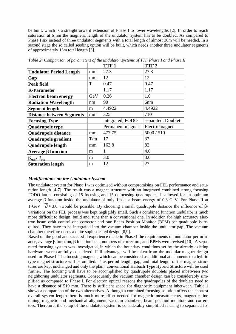
cusing. In addition the difficult temperature control of the undulator region can be omitted in Phase II.In Phase I the stringent mechanical stability requirements lead to a temperature control specification of±0.3K. In Phase II this can be relaxed to ±1.0 K so that a separate compartment for the undulator is nolonger needed. Since the whole setup includes fewer quadrupoles it will be easier to commission andoperate.But there are also drawbacks, which have to be mentioned: First, debunching occurs in the quadrupoledoublets. Second, the resulting average β-function is larger than its optimum values and for geometri-cal reasons cannot be made smaller. Both effects lead to an increase in saturation length of a few me-ters. These issues were worked out in detail in Ref [10]. A comparison of key device parameters be-tween Phase I using the combined focusing and Phase II with the separated solution is shown inTable 2. Fig.1 shows a 3D view of the undulator system as it will be installed in the TTF tunnel.
Fig.: 1 The FEL undulator set up in the tunnel for phase II. The beam enters the undulators from the left. Thebending magnet at the end deflects the beam down towards the dump.
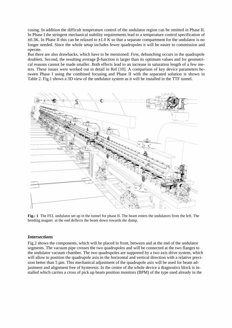
IntersectionsFig.2 shows the components, which will be placed in front, between and at the end of the undulatorsegments. The vacuum pipe crosses the two quadrupoles and will be connected at the two flanges tothe undulator vacuum chamber. The two quadrupoles are supported by a two axis drive system, whichwill allow to position the quadrupole axis in the horizontal and vertical direction with a relative preci-sion better than 5 µm. This mechanical adjustment of the quadrupole axis will be used for beam ad-justment and alignment free of hysteresis. In the centre of the whole device a diagnostics block is in-stalled which carries a cross of pick up beam position monitors (BPM) of the type used already in the
wire scanner (vertical)
pick up BPM
beam
wire scanner (horizontal)
quadrupole x – y drive
quadrupole
pump
diagnostics block
Fig.: 2 The diagnostic and beam optics station between two adjacent undulator segments
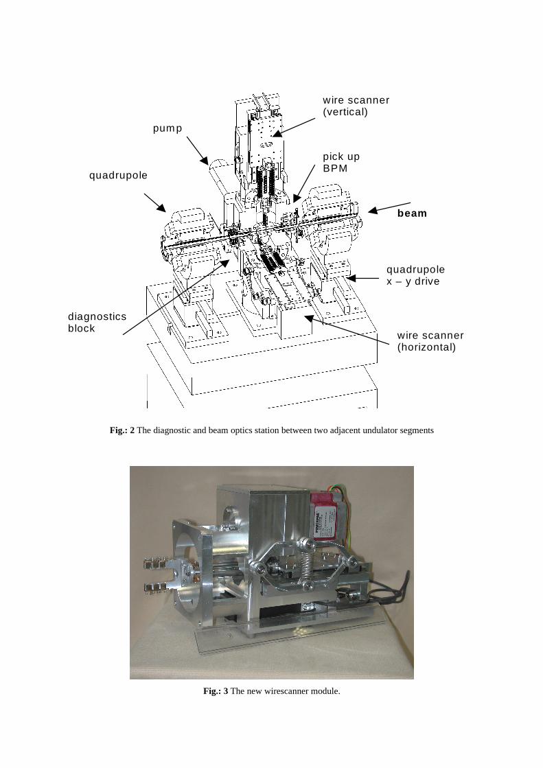
Fig.: 3 The new wirescanner module.
undulator vacuum chamber TTF phase I. Additionally, two wire scanners for horizontal and verticalscans of the electron beam are attached to the block. To reduce the size and the weight of the whole setup a new scanner type was developed. Fig.:3 shows a photograph of the first prototype. First tests ofthe mechanics were done successfully at DESY-Zeuthen. The fork with the wires (to be seen on theleft side of Fig. 3) is driven by a special reverse spindle drive powered by a stepping motor. The an-ticipated maximum scanning speed of 1m/s has been achieved. In the slow speed operation mode alinear resolution better than 5 •m will be possible.To fulfil the high demands on position stability and precision, all components are mounted on a gran-ite bench which is supported by a concrete block. A wire system to control the long term stability ofall 7 devices relative to each other is under discussion.
Vacuum Chambers
The new set up simplifies the requirements on the vacuum chambers. We will use the proven vacuumchamber design using extruded aluminum profiles developed at the APS [9]. It will be fully based onthe design used for Phase I. However, for Phase II only one or two BPMs and correctors are neededinside the undulator chamber. To which extend these components are still needed at all is presentlyunder discussion. The vacuum chambers will be manufactured in 2002 by our collaboration partners atthe APS in Chicago.
Quadrupole alignment
One of the most important issues in a Free Electron Laser (FEL) is the transverse overlap of electronand photon beam. One main reason for beam misalignment is misalignment of quadrupoles. It is oneof the great advantages of the separated focusing structure chosen for Phase II to have electromagneticquadrupoles. Their strength can be chosen independently of the electron beam energy. This will allowfor better, faster and more efficient beam based alignment techniques. For permanent magnet quad-rupoles, as used in Phase I the only means of checking quadrupole offsets is the variation of the elec-tron beam energy, which requires very stable operating conditions. Appropriate alignment procedureshave been proposed [11,12]. The advantage of separated focusing is that on one hand less focusingelements are needed, resulting in less kicks of the electron beam. On the other hand, the alignmentprocedure can now be performed by varying the quadrupole strength instead of changing the beamenergy. Thus, the electron beam energy does not have to be changed at all allowing for a more stableoperation.
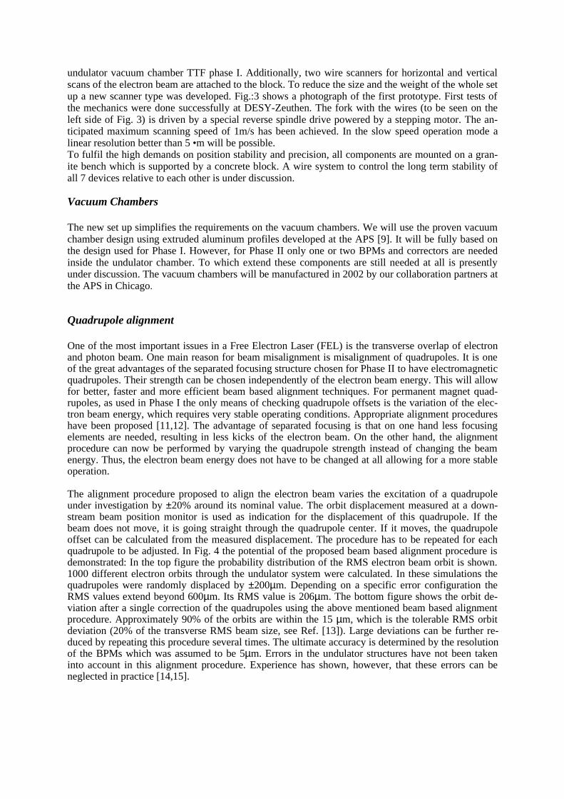
The alignment procedure proposed to align the electron beam varies the excitation of a quadrupoleunder investigation by ±20% around its nominal value. The orbit displacement measured at a down-stream beam position monitor is used as indication for the displacement of this quadrupole. If thebeam does not move, it is going straight through the quadrupole center. If it moves, the quadrupoleoffset can be calculated from the measured displacement. The procedure has to be repeated for eachquadrupole to be adjusted. In Fig. 4 the potential of the proposed beam based alignment procedure isdemonstrated: In the top figure the probability distribution of the RMS electron beam orbit is shown.1000 different electron orbits through the undulator system were calculated. In these simulations thequadrupoles were randomly displaced by ±200µm. Depending on a specific error configuration theRMS values extend beyond 600µm. Its RMS value is 206µm. The bottom figure shows the orbit de-viation after a single correction of the quadrupoles using the above mentioned beam based alignmentprocedure. Approximately 90% of the orbits are within the 15 µm, which is the tolerable RMS orbitdeviation (20% of the transverse RMS beam size, see Ref. [13]). Large deviations can be further re-duced by repeating this procedure several times. The ultimate accuracy is determined by the resolutionof the BPMs which was assumed to be 5µm. Errors in the undulator structures have not been takeninto account in this alignment procedure. Experience has shown, however, that these errors can beneglected in practice [14,15].
Figure 4: Effectivity of the beam based alignment procedure: The RMS orbit displacement of quad-rupole misalignment of ±200µm is shown in the top figure. 1000 different configurations were calcu-lated. Bottom: RMS after one alignment step. The assumed resolution of the beam position monitors is5 µm. Initial beam jitter is not taken into account.
References* Annual reports are available under: http://www-hasylab.desy.de/science/annual_reports/main.htm1. J. Andruskow et. al., Phys. Rev. Lett. 85 (2000) 38252. W. Brefeld et. al, Nucl. Instr. and Methods A375 (1996) 2953. J. Feldhaus, E.L. Saldin, J.R. Schneider, E.A. Schneidmiller, M.V.Yurkov, Opt. Commun. 140, (1997) 341-
3524. J. Pflüger, Y. M. Nikitina, Nucl. Instr. and Methods A381 (1996) 5545. See: http://www-hasylab.desy.de/facility/fel/main.htm for a compact description of the undulator for Phase I6. J. Pflüger, U. Hahn, HASYLAB Annual Report 1999 p 89 ff *7. J. Pflüger, B. Faatz, HASYLAB Annual Report 1998 p 104 ff *8. U. Hahn, HASYLAB Annual Report 1998 p 110 ff *9. U. Hahn, P.K. den Hartog, J. Pflüger, M. Rüter, G. Schmidt, E.M. Trakhtenberg, Nucl. Instr. and Methods
A445 (2000) 44210. B. Faatz, J. Pflüger, HASYLAB Annual Report 2000 p 89 ff , Proceedings of the FEL 2000 Aug. 13-18,
2000 Durham, North Carolina, USA, in Press *11. P. Castro, TTF FEL Beam-based Alignment by Dispersion Correction Using Micado Algorithm, TESLA
FEL report 1997-04, DESY, Hamburg.12. K. Flöttmann, B. Faatz, E. Czuchry and J. Roßbach, Nucl. Instr. Meth. A416 (1998) 152.13. B. Faatz, J. Pflüger, Yu.M. Nikitina, Nucl. Instr. Meth. A393 (1997)380.14. J. Pflüger, H. Lu, T. Teichmann, Nucl. Instr. Meth. A429 (1999) 386.15. J. Pflüger, P. Gippner, A. Swiderski, T. Vielitz, presented at the International Free Electron Laser Confer-
ence, August 23-26, 1999, DESY, Hamburg, Germany. Nucl. Instr. Meth. A445 (2000) II-87