Embed Size (px)
Citation preview

1MRS752304-MUM Issued: 10/1998 Version: F/23.6.2005
Data subject to change without notice
Freq1St_Underfrequency or Overfrequency
ProtectionStages 1, 2, 3, 4 and 5
Contents
1. Introduction ................................................................................................ 2
1.1 Features................................................................................................ 2 1.2 Application ............................................................................................ 2 1.3 Input description ................................................................................... 3 1.4 Output description................................................................................. 3
2. Description of operation............................................................................ 4
2.1 Configuration ........................................................................................ 4 2.2 Measuring mode ................................................................................... 5 2.3 Operation criteria .................................................................................. 5 2.4 Setting groups....................................................................................... 7 2.5 Test mode............................................................................................. 7 2.6 START and TRIP outputs ..................................................................... 9 2.7 Resetting............................................................................................... 9
3. Parameters and events............................................................................ 10
3.1 General ............................................................................................... 10 3.2 Setting values ..................................................................................... 11
3.2.1 Actual settings ........................................................................... 11 3.2.2 Setting group 1 .......................................................................... 11 3.2.3 Setting group 2 .......................................................................... 12 3.2.4 Control settings.......................................................................... 13
3.3 Measurement values........................................................................... 14 3.3.1 Input data................................................................................... 14 3.3.2 Output data ................................................................................ 14 3.3.3 Recorded data ........................................................................... 14 3.3.4 Events........................................................................................ 19
4. Technical data .......................................................................................... 20

Freq1St_
Distribution Automation
2
1. Introduction
1.1 Features
• Selectable underfrequency or overfrequency protection • Selectable frequency rate of change function • Start and trip indication in terms of output signals • Definite-time (DT) operation • Virtual phase-to-phase voltage measurement channels can be used instead of the
corresponding analogue measurement channels
1.2 Application
This document specifies the functions of the five underfrequency or overfrequency function blocks Freq1St1, Freq1St2, Freq1St3, Freq1St4 and Freq1St5 used in products based on the RED 500 Platform. All the five stages are identical in operation.
The frequency function blocks are specially designed for applications such as generator protection, load shedding, load restoration and disconnection for island operation.
Table 1 . Protection diagram symbols used in the relay terminal
ABB IEC ANSI
Freq1St1 f1 81-1
Freq1St2 f2 81-2
Freq1St3 f3 81-3
Freq1St4 f4 81-4
Freq1St5 f5 81-5
For IEC symbols used in single line diagrams, refer to the manual “Technical Descriptions of Functions, Introduction”, 1MRS750528-MUM.
Distribution Automation
Freq1St_
3
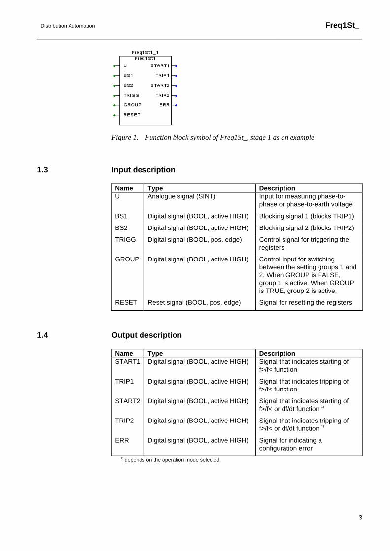
Figure 1. Function block symbol of Freq1St_, stage 1 as an example
1.3 Input description
Name Type Description U Analogue signal (SINT) Input for measuring phase-to-
phase or phase-to-earth voltage
BS1 Digital signal (BOOL, active HIGH) Blocking signal 1 (blocks TRIP1)
BS2 Digital signal (BOOL, active HIGH) Blocking signal 2 (blocks TRIP2)
TRIGG Digital signal (BOOL, pos. edge) Control signal for triggering the registers
GROUP Digital signal (BOOL, active HIGH) Control input for switching between the setting groups 1 and 2. When GROUP is FALSE, group 1 is active. When GROUP is TRUE, group 2 is active.
RESET Reset signal (BOOL, pos. edge) Signal for resetting the registers
1.4 Output description
Name Type Description START1 Digital signal (BOOL, active HIGH) Signal that indicates starting of
f>/f< function
TRIP1 Digital signal (BOOL, active HIGH) Signal that indicates tripping of f>/f< function
START2 Digital signal (BOOL, active HIGH) Signal that indicates starting of f>/f< or df/dt function 1)
TRIP2 Digital signal (BOOL, active HIGH) Signal that indicates tripping of f>/f< or df/dt function 1)
ERR Digital signal (BOOL, active HIGH) Signal for indicating a configuration error
1) depends on the operation mode selected

Freq1St_
Distribution Automation
4
2. Description of operation
2.1 Configuration
The input and output signals of the frequency protection function block Freq1St_ is configured with the Relay Configuration Tool included in the CAP 505 Tool Box.
Frequency protection must be selected for the voltage input via the special measurements dialogue box in the configuration tool. If the frequency protection is not selected, the ERR output is activated.
Traditionally, frequency measurement is highly recommended to be based on a phase-to-phase voltage which is less dependent on the asymmetry of separate phase voltages and less sensitive to harmonics. The third harmonic, for instance, will not be present in phase-to-phase voltages. However, the function block is also able to measure the frequency reliably and accurately using a single phase-to earth voltage. The function block will check that the signal type of the U input is valid, i.e. a phase-to-phase or phase-to-earth voltage. A wrong signal type will cause a configuration error.
The output signals TRIP1 and TRIP2 of the function block can be used for frequency-based load shedding in an underfrequency situation. Some portions of the load can be reduced by disconnecting the corresponding outgoing lines from the busbar. When the remaining load is in balance with the power generation available, the power system frequency will return to its normal value.
The outputs can also be used in frequency-based load restoration. The Relay Configuration Tool is used for configuring the logic needed for load restoration after load shedding.
Please note that the task execution interval of the function block must be configured to the fastest task, i.e. 5ms (fn = 50 Hz). A slower task execution interval will cause a configuration error which will force the function block to the “Not in use” mode.

Distribution Automation
Freq1St_
5
2.2 Measuring mode
The actual power system frequency is measured via a sophisticated numerical method. The operation is insensitive to harmonics and the DC component.
2.3 Operation criteria
The function block Freq1St_ can be used for underfrequency (f<) or overfrequency (f>) protection. The function block operates as either underfrequency or overfrequency relays depending on whether the set operate value is above or below the rated frequency of the relay or feeder terminal.
The function block also includes a starting element that measures the rate of change of the power system frequency, so that the need for protection can be anticipated even before a major frequency change occurs. The parameter “Operation Mode” is used for setting the operation direction of the df/dt function. When the set value is indicated as “df/dt<”, the negative rate of change of frequency is measured (the function block operates as a negative derivative function), and when the set value is indicated as “df/dt>”, the positive rate of change of frequency is measured (the function block operates as a positive derivative function). The frequency rate of change function can also be set out of use.
The output START1 is activated when the f</f> function starts. Correspondingly, START2 is activated when the f</f> or df/dt function starts, depending on the operation mode used. The trip signals of both the f</f> function and the df/dt function (TRIP1 and TRIP2) can be used for load shedding. The operate time of the f</f> function can be set via the parameter “Operate time 1” and the operate time of both the f</f> function and the df/dt function via the parameter “Operate time 2”. Active START1 and START2 signals are both indicated by steady start LEDs (yellow) and active TRIP1 and TRIP2 signals by steady trip LEDs (red) on the MMI.
The setting parameter “Operation mode” is used to select the operation mode of the function as follows:
Freq1St_
Distribution Automation
6
Operation mode Description of operation =Not in use The f</f> function and the df/dt function are not in use.
=f</f> 1 timer TRIP1 is activated by the f</f> function when the set operate time 1 has elapsed. The df/dt function is not in use.
=f</f> 2 timers TRIP1 is activated by the f</f> function when the set operate time 1 has elapsed, and TRIP2 is activated by the f</f> function when the set operate time 2 has elapsed. The df/dt function is not in use.
=f</f> OR df/dt> TRIP1 is activated by the f</f> function when the set operate time 1 has elapsed, and TRIP2 is activated by the f</f> function or the positive df/dt function when the set operate time 2 has elapsed.
=f</f> AND df/dt> TRIP1 is activated by the f</f> function when the set operate time 1 has elapsed. TRIP2 is activated by both the f</f> function and the positive df/dt function when the set operate time 2 has elapsed.
=f</f> OR df/dt< TRIP1 is activated by the f</f> function when the set operate time 1 has elapsed, and TRIP2 is activated by the f</f> function or the negative df/dt function when the set operate time 2 has elapsed.
=f</f> AND df/dt< TRIP1 is activated by the f</f> function when the set operate time 1 has elapsed. TRIP2 is activated by both the f</f> function and the negative df/dt function when the set operate time 2 has elapsed.
The calculation window for frequency measurement always has a length of two fundamental cycles, i.e. 40 ms at the rated system frequency 50 Hz and 33.3 ms at the rated system frequency 60 Hz. The total operate time is the sum of the start time, the additional operate delay and the operate delay of the heavy-duty output relay. The timers are cleared when the abnormal frequency situation has disappeared.
The blocking signal BS1 can be used for blocking the operation of the underfrequency and overfrequency function f</f>. When the blocking signal BS1 is active, the DT timer 1 is frozen. In the same way, the blocking signal BS2 can be used for blocking the operation of the df/dt or f</f> function, depending on the operation mode used. When the blocking signal BS2 is active, the DT timer 2 is frozen. Active BS1 and BS2 signals are indicated by blinking start LEDs (yellow) on the MMI.
In an undervoltage situation the function block is internally blocked. The undervoltage limit value is set according to the application.

Distribution Automation
Freq1St_
7
Figure 2. Simplified functional block diagram of an underfrequency and overfrequency protection function block
Note! The operate times and start times are specified for the set rated frequencies 50 Hz and 60 Hz.
Also note that the setting range of “Operate time 2” also covers up to 300.00s. However, when df/dt operation mode for TRIP2 is used, the actual setting range of “Operate time 2” is smaller due to the fact that the minimum “Start df/dt” setting is 0.2 Hz/s and the accurate operating frequency of the function block is 25...75Hz.
2.4 Setting groups
Two different groups of setting values, group 1 and group 2, are available for the function block Freq1St_. Switching between the two groups can be done in the following three ways:
1 Locally via the control parameter “Group selection”1) of the MMI 2 Over the communication bus by writing the parameter V11) 3 By means of the input signal GROUP when allowed via the parameter “Group
selection” (i.e. when V1 = 21)). 1) Group selection (V1): 0 = Group 1; 1 = Group 2; 2 = GROUP input
The control parameter “Active group” indicates the setting group valid at a given time.
2.5 Test mode
The digital outputs of the function block Freq1St_ can be activated with separate control parameters for each output either locally via the MMI or externally via the

Freq1St_
Distribution Automation
8
serial communication. When an output is activated with the test parameter, an event indicating the test is generated.
The protection functions operate normally while the outputs are tested.

Distribution Automation
Freq1St_
9
2.6 START and TRIP outputs
The output signals START1 and START2 are always pulse-shaped. The minimum pulse width of the corresponding output signal is set via a separate parameter on the MMI or on serial communication. If the start situation is longer than the set pulse width, the START1 and START2 signals remain active until the start situation is over. The output signals TRIP1 and TRIP2 may be non-latching or latching. When the latching mode has been selected, the TRIP1 and TRIP2 signals remain active until the output is reset even if the operation criteria have reset.
Active START1 and START2 signals are indicated by steady start LEDs (yellow) and active TRIP1 and TRIP2 signals by steady trip LEDs (red) on the MMI.
2.7 Resetting
The TRIP output signals and the registers can be reset either via the RESET input or over the serial bus or the local MMI.
The operation indicators, latched trip signal and recorded data can be reset as follows:
Operation indicators
Latched trip signal
Recorded data
RESET input of the function block 1) X X
Parameter F072V013 1) X X
General parameter F001V011 2) X
General parameter F001V012 2) X X
General parameter F001V013 2) X X X
Push-button C 2) X
Push-buttons C + E (2 s) 2) X X
Push-buttons C + E (5 s) 2) X X X 1) Resets the latched trip signal and recorded data of the function block Freq1St1. The corresponding parameters for other Freq1St_ function blocks are the following: Freq1St2 F073V013 Freq1St3 F074V013 Freq1St4 F075V013 Freq1St5 F076V013 2) Affects all function blocks

Freq1St_
Distribution Automation
10
3. Parameters and events
3.1 General
• Each function block has a specific channel number for serial communication parameters and events. The channels for the frequency function blocks are the following: Function block Channel Freq1St1 72
Freq1St2 73
Freq1St3 74
Freq1St4 75
Freq1St5 76
• The data direction of the parameters defines the use of each parameter as follows: Data direction Description R, R/M Read only
W Write only
R/W Read and write
• The different event mask parameters (see section “Control settings”) affect the visibility of events on the MMI or on serial communication (LON or SPA) as follows: Event mask 1 (FxxxV101/102) SPA / MMI (LON)
Event mask 2 (FxxxV103/104) LON
Event mask 3 (FxxxV105/106) LON
Event mask 4 (FxxxV107/108) LON
For example, if only the events E3, E4 and E5 are to be seen on the MMI of the relay terminal, the event mask value 56 (8 + 16 + 32) is written to the “Event mask 1” parameter (FxxxV101).
In case a function block includes more than 32 events, there are two parameters instead of e.g. the “Event mask 1” parameter: the parameter “Event mask 1A” (FxxxV101) covers the events 0...31 and “Event mask 1B”(FxxxV102) the events 32...63.

Distribution Automation
Freq1St_
11
3.2 Setting values
3.2.1 Actual settings
Parameter Code Values Unit Default Data direction
Explanation
Operation mode S1 0...6 1) - 1 R/M Operation mode for frequency
protection
Voltage limit S2 0.30...0.90 x Un 0.30 R/M Undervoltage limit for blocking
Start frequency S3 25.00...75.00 Hz 48.70 R/M Start value for U/O frequency
protection
Operate time 1 S4 0.10...300.00 s 20.00 R/M Operate time for U/O frequency
protection
Start df/dt S5 0.2...10.0 Hz/s 10.0 R/M Start value for frequency rate of
change prot.
Operate time 2 S6 0.12...300.00 s 20.00 R/M Timer for df/dt prot. or U/O
frequency prot.
1) Operation mode 0 = Not in use 1 = f</f> 1 timer 2 = f</f> 2 timers 3 = f</f> OR df/dt> 4 = f</f> AND df/dt> 5 = f</f> OR df/dt< 6 = f</f> AND df/dt<
3.2.2 Setting group 1
Parameter Code Values Unit Default Data direction
Explanation
Operation mode S41 0...6 1) - 1 R/W Operation mode for frequency
protection
Voltage limit S42 0.30...0.90 x Un 0.30 R/W Undervoltage limit for blocking
Start frequency S43 25.00...75.00 Hz 48.70 R/W Start value for U/O frequency
protection
Operate time 1 S44 0.10... 300.00 s 20.00 R/W Operate time for U/O frequency
protection
Start df/dt S45 0.2...10.0 Hz/s 10.0 R/W Start value for frequency rate of
change prot.
Operate time 2 S46 0.12... 300.00 s 20.00 R/W Timer for df/dt prot. or U/O
frequency prot.
1) Operation mode 0 = Not in use 1 = f</f> 1 timer 2 = f</f> 2 timers 3 = f</f> OR df/dt> 4 = f</f> AND df/dt> 5 = f</f> OR df/dt< 6 = f</f> AND df/dt<

Freq1St_
Distribution Automation
12
3.2.3 Setting group 2
Parameter Code Values Unit Default Data direction
Explanation
Operation mode S71 0...6 1) - 1 R/W Operation mode for frequency
protection
Voltage limit S72 0.30...0.90 x Un 0.30 R/W Undervoltage limit for blocking
Start frequency S73 25.00...75.00 Hz 48.70 R/W Start value for U/O frequency
protection
Operate time 1 S74 0.10... 300.00 s 20.00 R/W Operate time for U/O frequency
protection
Start df/dt S75 0.2...10.0 Hz/s 10.0 R/W Start value for frequency rate of
change prot.
Operate time 2 S76 0.12... 300.00 s 20.00 R/W Timer for df/dt prot. or U/O
frequency prot.
1) Operation mode 0 = Not in use 1 = f</f> 1 timer 2 = f</f> 2 timers 3 = f</f> OR df/dt> 4 = f</f> AND df/dt> 5 = f</f> OR df/dt< 6 = f</f> AND df/dt<
Distribution Automation
Freq1St_
13
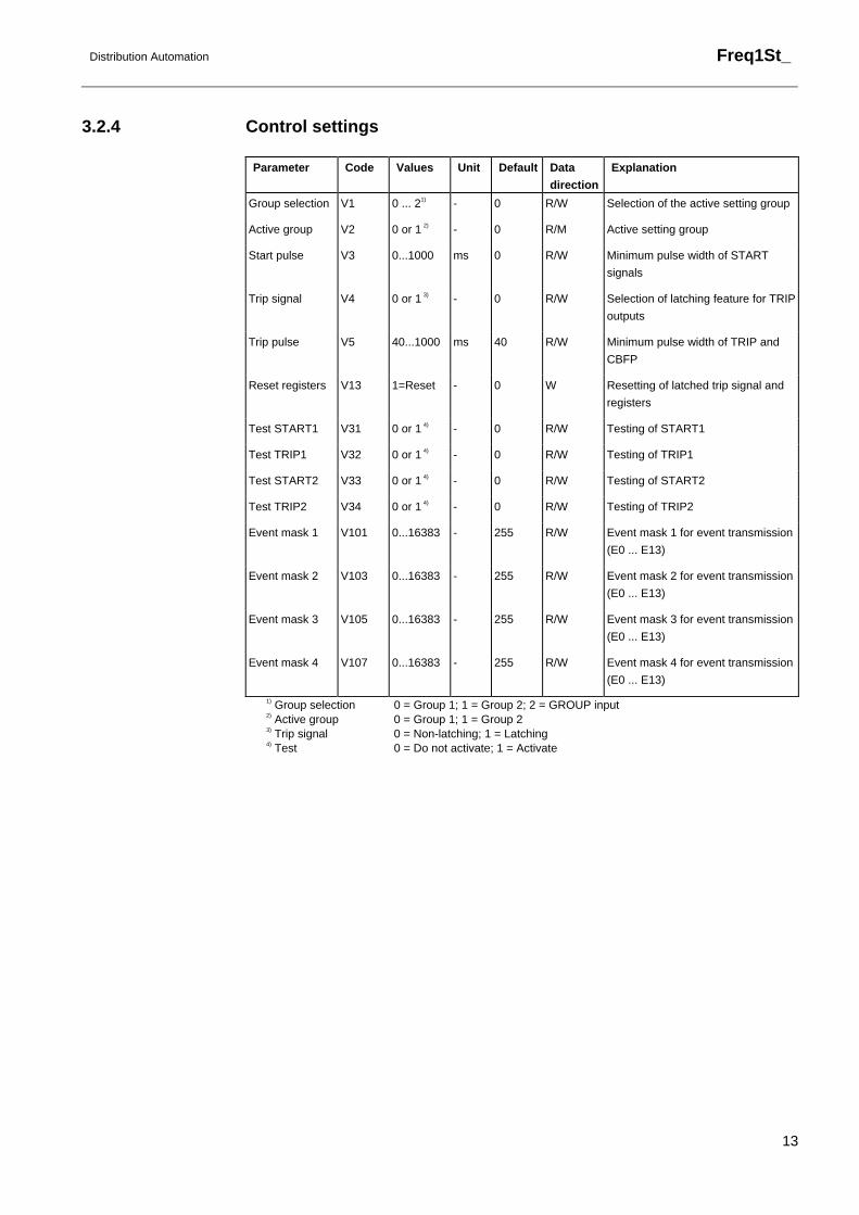
3.2.4 Control settings
Parameter Code Values Unit Default Data direction
Explanation
Group selection V1 0 ... 21) - 0 R/W Selection of the active setting group
Active group V2 0 or 1 2) - 0 R/M Active setting group
Start pulse V3 0...1000 ms 0 R/W Minimum pulse width of START
signals
Trip signal V4 0 or 1 3) - 0 R/W Selection of latching feature for TRIP outputs
Trip pulse V5 40...1000 ms 40 R/W Minimum pulse width of TRIP and CBFP
Reset registers V13 1=Reset - 0 W Resetting of latched trip signal and registers
Test START1 V31 0 or 1 4) - 0 R/W Testing of START1
Test TRIP1 V32 0 or 1 4) - 0 R/W Testing of TRIP1
Test START2 V33 0 or 1 4) - 0 R/W Testing of START2
Test TRIP2 V34 0 or 1 4) - 0 R/W Testing of TRIP2
Event mask 1 V101 0...16383 - 255 R/W Event mask 1 for event transmission
(E0 ... E13)
Event mask 2 V103 0...16383 - 255 R/W Event mask 2 for event transmission (E0 ... E13)
Event mask 3 V105 0...16383 - 255 R/W Event mask 3 for event transmission (E0 ... E13)
Event mask 4 V107 0...16383 - 255 R/W Event mask 4 for event transmission (E0 ... E13)
1) Group selection 0 = Group 1; 1 = Group 2; 2 = GROUP input 2) Active group 0 = Group 1; 1 = Group 2 3) Trip signal 0 = Non-latching; 1 = Latching 4) Test 0 = Do not activate; 1 = Activate

Freq1St_
Distribution Automation
14
3.3 Measurement values
3.3.1 Input data
Parameter Code Values Unit Default Data direction
Explanation
Frequency I1 20.00...80.00 Hz 0.0 R/M System frequency
Rate of change I2 -15.0...+15.0 Hz/s 0.0 R/M Freq. rate of change
Voltage U I3 0.0...2.0 x Un 0.0 R/M Voltage U
Input BS1 I4 0 or 1 1) - 0 R/M Block signal BS1
Input BS2 I5 0 or 1 1) - 0 R/M Block signal BS2
Input TRIGG I6 0 or 1 1) - 0 R/M Signal for triggering the
registers
Input GROUP I7 0 or 1 1) - 0 R/M Signal for switching between
the groups 1 and 2
Input RESET I8 0 or 1 1) - 0 R/M Signal for resetting the
output signals and registers
of Freq1St_
1) Input 0 = Not active; 1 = Active
3.3.2 Output data
Parameter Code Values Unit Default Data direction
Explanation
Output START1 O1 0 or 1 1) - 0 R/M Status of start signal 1
Output TRIP1 O2 0 or 1 1) - 0 R/M Status of trip signal 1
Output START2 O3 0 or 1 1) - 0 R/M Status of start signal 2
Output TRIP2 O4 0 or 1 1) - 0 R/M Status of trip signal 2
1) Output 0 = Not active; 1 = Active
3.3.3 Recorded data
3.3.3.1 General
The information required for later fault analysis is recorded when the function block starts or trips, or when the recording function is triggered via the external TRIGG input.
The data of the last three events are stored in Recorded data 1…3, beginning from Recorded data 1. These registers are updated in a cyclical manner, where the values of the most recent event overwrite the oldest recorded data. If recorded data has been reset or the relay has been restarted, the first event is again stored in Recorded data 1.

Distribution Automation
Freq1St_
15
Registers containing information about the voltage, frequency, etc. can be accessed over the serial communication or the local MMI of the RED 500 unit.
3.3.3.2 Date and time
The time stamp indicates the rising edge of the START1, TRIP1, START2, TRIP2 or TRIGG signals.
3.3.3.3 Duration
The duration of a start situation is recorded separately for the operate timers 1 and 2 (refer to Figure 2). The durations are recorded as percentages of the set operate times. Timers are independent from each other, i.e. if both timers are running, the highest value reached will be recorded to both durations, regardless whether a trip has been commenced by either of the timers.
3.3.3.4 Frequency and voltage values
If the function block trips, the frequency and voltage values are updated at the moment of tripping i.e. on the rising edge of the TRIP signal. At external triggering, the frequency and voltage values are updated at the moment of triggering i.e. on the rising edge of the input signal TRIGG. If the function block starts but does not trip, the values captured one fundamental cycle (20 ms at rated frequency 50 Hz) after the beginning of the start situation are recorded.
3.3.3.5 Status data
The status data of the input signals BS1, BS2 and TRIGG and the output signals START1, START2, TRIP1 and TRIP2 as well as the parameter “Active group” are recorded at the moment of tripping and triggering. The “Active group” parameter indicates the setting group valid for the recorded data.
3.3.3.6 Priority
The priority of the recording function is the following:
1 Tripping 2 Starting 3 External triggering, which means that if the function has started, it will neglect an external triggering request.

Freq1St_
Distribution Automation
16
3.3.3.7 Recorded data 1
Parameter Code Values Unit Default Data direction
Explanation
Date V201 YYYY-MM-DD - - R/M Recording date
Time V202 hh:mm:ss.mss - - R/M Recording time
Start1 V203 0 or 1 1) - 0 R/M Status of START1
Start2 V204 0 or 1 1) - 0 R/M Status of START2
Duration1 V205 0.0...100.0 % 0.0 R/M Duration of START1 situation
Duration2 V206 0.0...100.0 % 0.0 R/M Duration of START2 situation
Trip1 V207 0 or 1 1) - 0 R/M Status of TRIP1
Trip2 V208 0 or 1 1) - 0 R/M Status of TRIP2
Frequency V209 20.00...80.00 Hz 0.0 R/M Meas. system frequency
Rate of change V210 -15.0...+15.0 Hz/s 0.0 R/M Freq. rate of change
Voltage U V211 0.0...2.0 x Un 0.0 R/M Meas. voltage
BS1 V212 0 or 1 1) - 0 R/M Status of BS1
BS2 V213 0 or 1 1) - 0 R/M Status of BS2
TRIGG V214 0 or 1 1) - 0 R/M Status of TRIGG
Active group V215 0 or 1 2) - 0 R/M Active setting group
1) Status 0 = Not active; 1 = Active 2) Active group 0 = Group 1; 1 = Group 2
Distribution Automation
Freq1St_
17
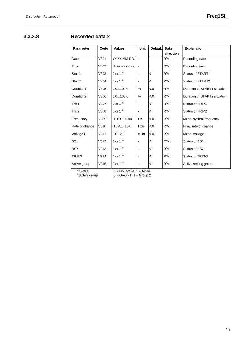
3.3.3.8 Recorded data 2
Parameter Code Values Unit Default Data direction
Explanation
Date V301 YYYY-MM-DD - - R/M Recording date
Time V302 hh:mm:ss.mss - - R/M Recording time
Start1 V303 0 or 1 1) - 0 R/M Status of START1
Start2 V304 0 or 1 1) - 0 R/M Status of START2
Duration1 V305 0.0...100.0 % 0.0 R/M Duration of START1 situation
Duration2 V306 0.0...100.0 % 0.0 R/M Duration of START2 situation
Trip1 V307 0 or 1 1) - 0 R/M Status of TRIP1
Trip2 V308 0 or 1 1) - 0 R/M Status of TRIP2
Frequency V309 20.00...80.00 Hz 0.0 R/M Meas. system frequency
Rate of change V310 -15.0...+15.0 Hz/s 0.0 R/M Freq. rate of change
Voltage U V311 0.0...2.0 x Un 0.0 R/M Meas. voltage
BS1 V312 0 or 1 1) - 0 R/M Status of BS1
BS2 V313 0 or 1 1) - 0 R/M Status of BS2
TRIGG V314 0 or 1 1) - 0 R/M Status of TRIGG
Active group V315 0 or 1 2) - 0 R/M Active setting group
1) Status 0 = Not active; 1 = Active 2) Active group 0 = Group 1; 1 = Group 2

Freq1St_
Distribution Automation
18
3.3.3.9 Recorded data 3
Parameter Code Values Unit Default Data direction
Explanation
Date V401 YYYY-MM-DD - - R/M Recording date
Time V402 hh:mm:ss.mss - - R/M Recording time
Start1 V403 0 or 1 1) - 0 R/M Status of START1
Start2 V404 0 or 1 1) - 0 R/M Status of START2
Duration1 V405 0.0...100.0 % 0.0 R/M Duration of START1
situation
Duration2 V406 0.0...100.0 % 0.0 R/M Duration of START2
situation
Trip1 V407 0 or 1 1) - 0 R/M Status of TRIP1
Trip2 V408 0 or 1 1) - 0 R/M Status of TRIP2
Frequency V409 20.00...80.00 Hz 0.0 R/M Meas. system frequency
Rate of change V410 -15.0...+15.0 Hz/s 0.0 R/M Freq. rate of change
Voltage U V411 0.0...2.0 x Un 0.0 R/M Meas. voltage
BS1 V412 0 or 1 1) - 0 R/M Status of BS1
BS2 V413 0 or 1 1) - 0 R/M Status of BS2
TRIGG V414 0 or 1 1) - 0 R/M Status of TRIGG
Active group V415 0 or 1 2) - 0 R/M Active setting group
1) Status 0 = Not active; 1 = Active 2) Active group 0 = Group 1; 1 = Group 2
Distribution Automation
Freq1St_
19
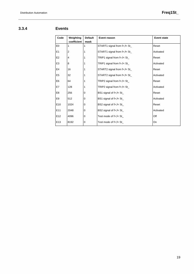
3.3.4 Events
Code Weighting coefficient
Default mask
Event reason Event state
E0 1 1 START1 signal from f>,f< St_ Reset
E1 2 1 START1 signal from f>,f< St_ Activated
E2 4 1 TRIP1 signal from f>,f< St_ Reset
E3 8 1 TRIP1 signal from f>,f< St_ Activated
E4 16 1 START2 signal from f>,f< St_ Reset
E5 32 1 START2 signal from f>,f< St_ Activated
E6 64 1 TRIP2 signal from f>,f< St_ Reset
E7 128 1 TRIP2 signal from f>,f< St_ Activated
E8 256 0 BS1 signal of f>,f< St_ Reset
E9 512 0 BS1 signal of f>,f< St_ Activated
E10 1024 0 BS2 signal of f>,f< St_ Reset
E11 2048 0 BS2 signal of f>,f< St_ Activated
E12 4096 0 Test mode of f>,f< St_ Off
E13 8192 0 Test mode of f>,f< St_ On
Freq1St_
Distribution Automation
20
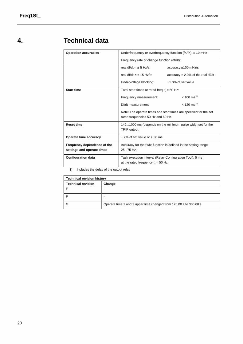
4. Technical data Operation accuracies Underfrequency or overfrequency function (f</f>): ± 10 mHz
Frequency rate of change function (df/dt):
real df/dt < ± 5 Hz/s: accuracy ±100 mHz/s
real df/dt < ± 15 Hz/s: accuracy ± 2.0% of the real df/dt
Undervoltage blocking: ±1.0% of set value
Start time Total start times at rated freq. fn = 50 Hz:
Frequency measurement: < 100 ms 1)
Df/dt measurement: < 120 ms 1)
Note! The operate times and start times are specified for the set
rated frequencies 50 Hz and 60 Hz.
Reset time 140...1000 ms (depends on the minimum pulse width set for the
TRIP output
Operate time accuracy ± 2% of set value or ± 30 ms
Frequency dependence of the settings and operate times
Accuracy for the f</f> function is defined in the setting range
25...75 Hz.
Configuration data Task execution interval (Relay Configuration Tool): 5 ms
at the rated frequency fn = 50 Hz
1) Includes the delay of the output relay
Technical revision history
Technical revision Change E -
F -
G Operate time 1 and 2 upper limit changed from 120.00 s to 300.00 s


![Digital 단상 과주파수 저주파수 계전기 사용 설명서 Digital Overfrequency & Underfrequency Relay (GD3-H11) Manual V1.11 경보전기[주] 2 안전을 위한 주의사항](https://img.pdfslide.us/doc/110x75/5f2b7b5a17b1f45cf66a8b4d/digital-ef-eoeoe-oeoe-ee-eoe-digital-overfrequency.jpg)