Embed Size (px)
Citation preview
Uncoated Plain Carbon SteelMaterial Variables
Uncoated Plain Carbon – Material variables
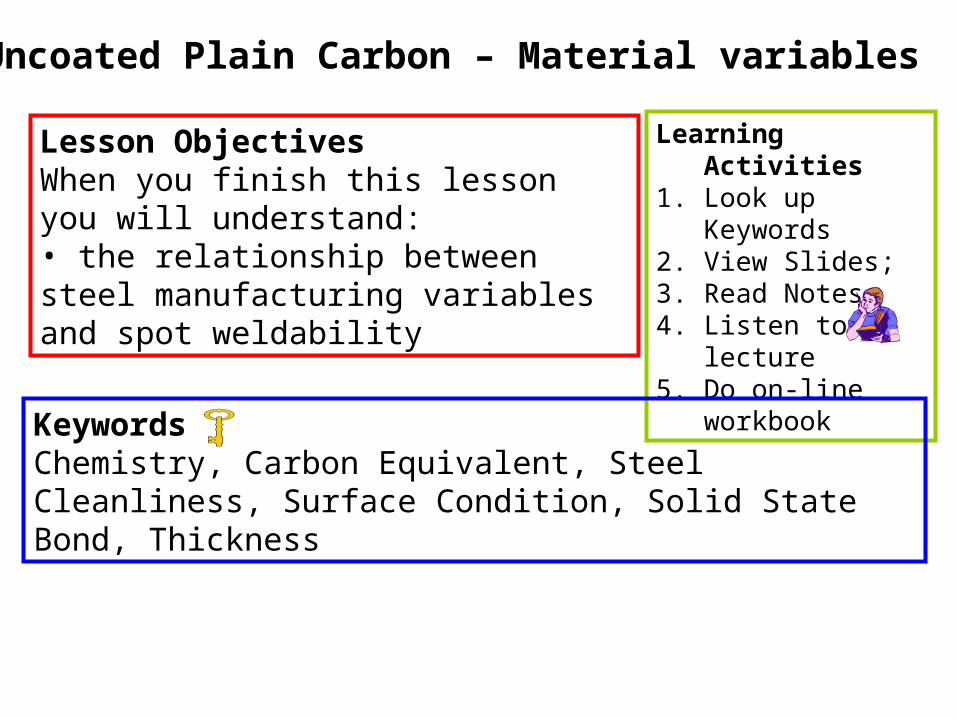
Lesson ObjectivesWhen you finish this lesson you will understand:• the relationship between steel manufacturing variables and spot weldability
Learning Activities1. Look up Keywords2. View Slides; 3. Read Notes, 4. Listen to lecture5. Do on-line
workbook
KeywordsChemistry, Carbon Equivalent, Steel Cleanliness, Surface Condition, Solid State Bond, Thickness
Material Variables
Process Parameters:
• Weld Current
• Weld Time
• Hold Time
• Upslope/Downslope
• Pulsing
• Electrode Force
• Postweld Temper
• Electrode Designs
Material Parameters:
• Chemistry• Cleanliness• Surface Condition• Material Processing• Thickness
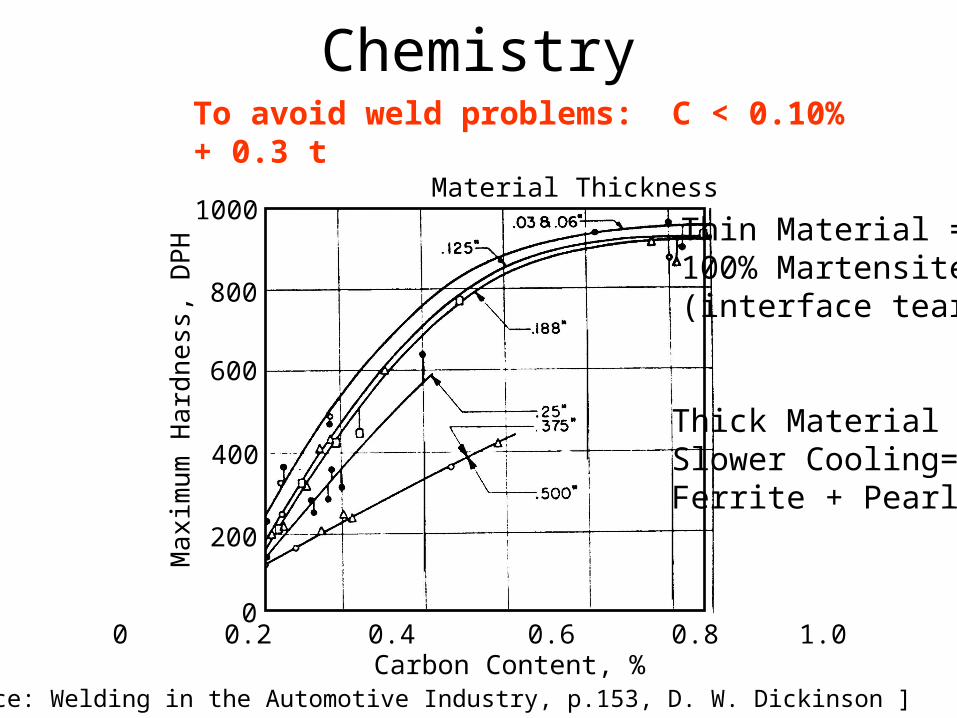
Chemistry
Material Thickness
Carbon Content, %
Ma
xim
um
Ha
rdn
ess
, DP
H1000
800
600
400
200
00 0.2 0.4 0.6 0.8 1.0
[Reference: Welding in the Automotive Industry, p.153, D. W. Dickinson ]
To avoid weld problems: C < 0.10% + 0.3 t
Thin Material =100% Martensite(interface tears)
Thick Material =Slower Cooling=Ferrite + Pearlite
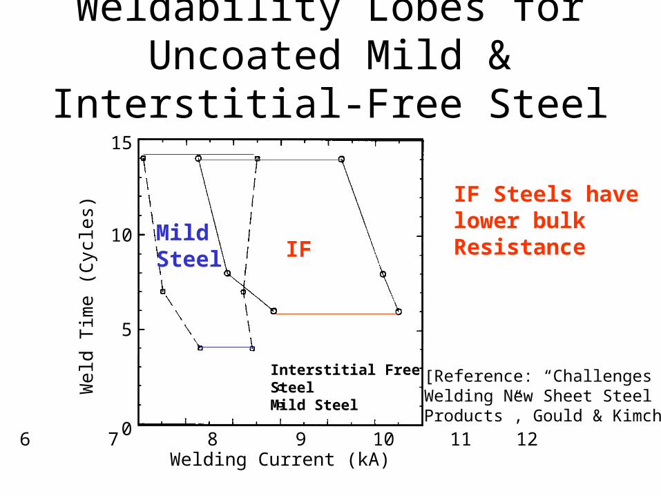
Weldability Lobes for Uncoated Mild & Interstitial-Free Steel
15
10
5
06 7 8 9 10 11 12
Interstitial FreeSteelMild Steel
Welding Current (kA)
We
ld T
ime
(Cyc
les)
[Reference: “Challenges inWelding New Sheet SteelProducts”, Gould & Kimchi]
IF Steels havelower bulk ResistanceIF
MildSteel
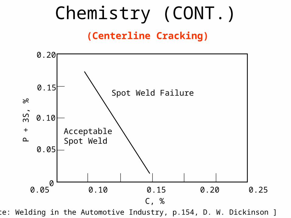
Chemistry (CONT.)
Spot Weld Failure
AcceptableSpot Weld
0 0.05 0.10 0.15 0.20 0.25 0.30
C, %
0.20
0.15
0.10
0.05
0
P +
3S
, %
[Reference: Welding in the Automotive Industry, p.154, D. W. Dickinson ]
(Centerline Cracking)
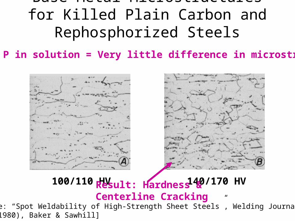
Base Metal Microstructures for Killed Plain Carbon and Rephosphorized Steels
[Reference: “Spot Weldability of High-Strength Sheet Steels”, Welding Journal 59(January 1980), Baker & Sawhill]
Since P in solution = Very little difference in microstructure
100/110 HV 140/170 HVResult: Hardness &Centerline Cracking
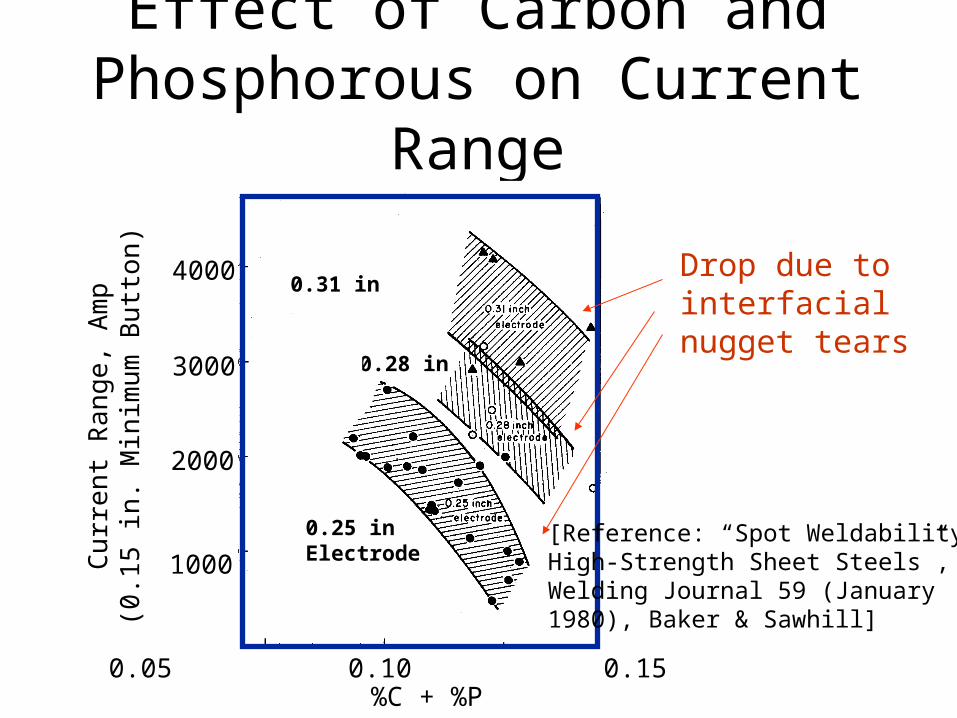
Effect of Carbon and Phosphorous on Current Range
0.31 in.
0.28 in
4000
3000
2000
1000
0.05 0.10 0.15%C + %P
Cu
rre
nt R
an
ge, A
mp
(0.1
5 in
. Min
imu
m B
utto
n)
[Reference: “Spot Weldability ofHigh-Strength Sheet Steels”, Welding Journal 59 (January1980), Baker & Sawhill]
0.25 inElectrode
Drop due to interfacial nugget tears
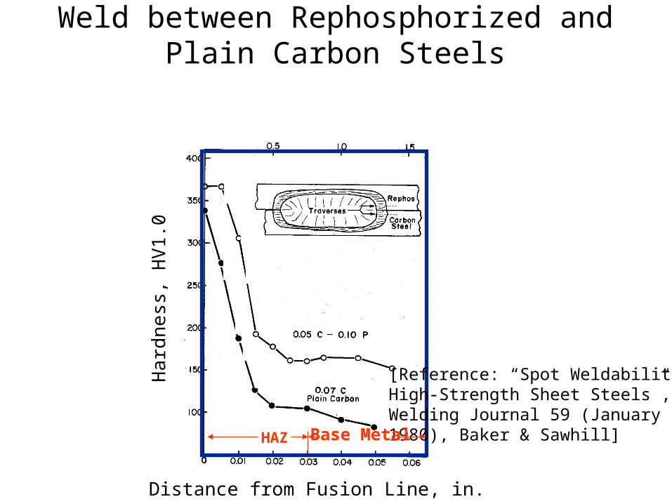
Hardness Transverses in a Spot Weld between Rephosphorized and Plain Carbon Steels
HAZ
Distance from Fusion Line, in.
Ha
rdne
ss, H
V1
.0
[Reference: “Spot Weldability ofHigh-Strength Sheet Steels”, Welding Journal 59 (January1980), Baker & Sawhill]Base Metal
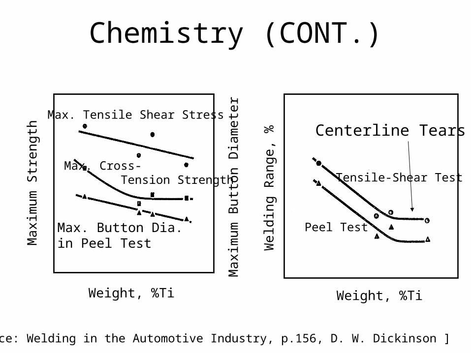
Chemistry (CONT.)
Max. Tensile Shear Stress
Max. Cross- Tension Strength
Max. Button Dia. in Peel Test
Weight, %Ti
Ma
xim
um
Str
en
gth
Ma
xim
um
But
ton
Dia
me
ter
Weight, %Ti
Tensile-Shear Test
Peel Test
We
ldin
g R
ang
e, %
[Reference: Welding in the Automotive Industry, p.156, D. W. Dickinson ]
Centerline Tears
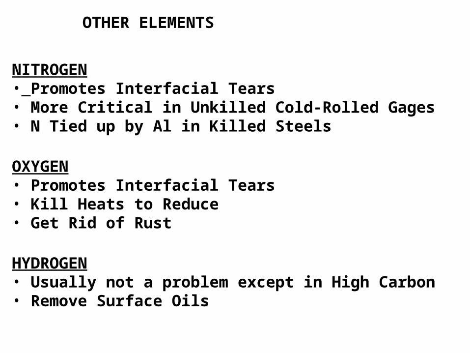
OTHER ELEMENTS
NITROGEN• Promotes Interfacial Tears• More Critical in Unkilled Cold-Rolled Gages• N Tied up by Al in Killed Steels
OXYGEN• Promotes Interfacial Tears• Kill Heats to Reduce• Get Rid of Rust
HYDROGEN• Usually not a problem except in High Carbon• Remove Surface Oils
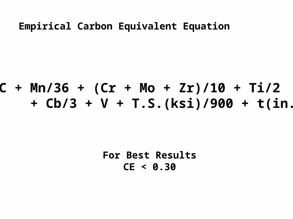
CE = C + Mn/36 + (Cr + Mo + Zr)/10 + Ti/2 + Cb/3 + V + T.S.(ksi)/900 + t(in.)/20
Empirical Carbon Equivalent Equation
For Best ResultsCE < 0.30
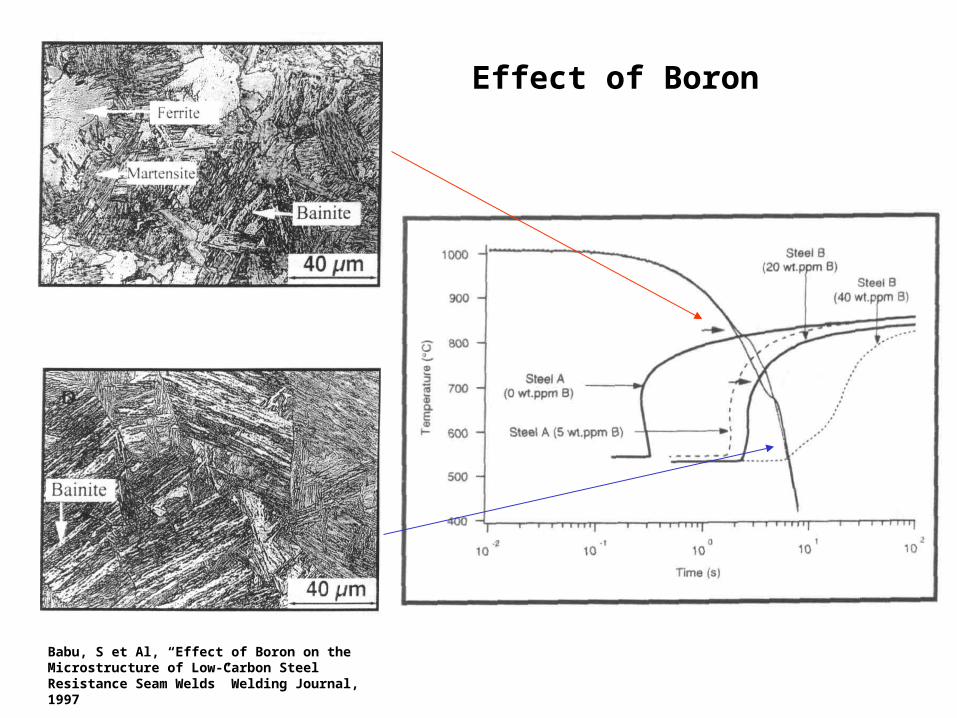
Effect of Boron
Babu, S et Al, “Effect of Boron on the Microstructure of Low-Carbon Steel Resistance Seam Welds” Welding Journal, 1997

Turn to the person sitting next to you and discuss (1 min.):• The chemistry effects in spot and seam welding of carbon steels are similar to those in GTAW at high travel speeds but somewhat more exaggerated. Considering solidification morphology, why should this be?
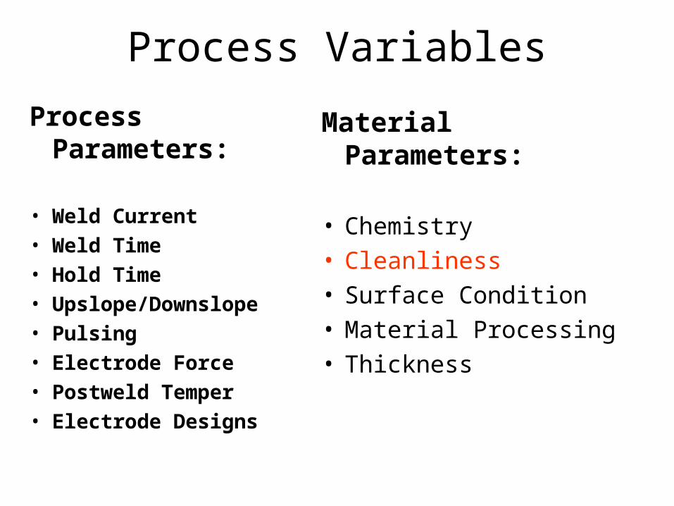
Process Variables
Process Parameters:
• Weld Current
• Weld Time
• Hold Time
• Upslope/Downslope
• Pulsing
• Electrode Force
• Postweld Temper
• Electrode Designs
Material Parameters:
• Chemistry• Cleanliness• Surface Condition• Material Processing• Thickness
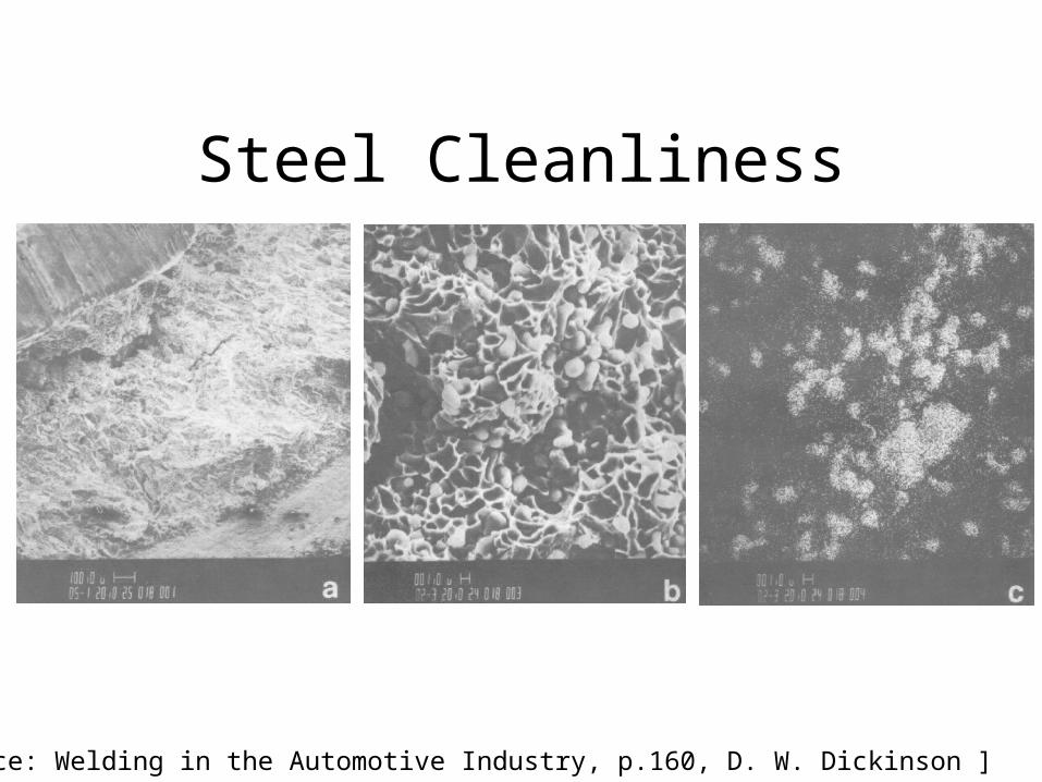
Steel Cleanliness
[Reference: Welding in the Automotive Industry, p.160, D. W. Dickinson ]

Process Variables
Process Parameters:
• Weld Current
• Weld Time
• Hold Time
• Upslope/Downslope
• Pulsing
• Electrode Force
• Postweld Temper
• Electrode Designs
Material Parameters:
• Chemistry• Cleanliness• Surface Condition• Material Processing• Thickness
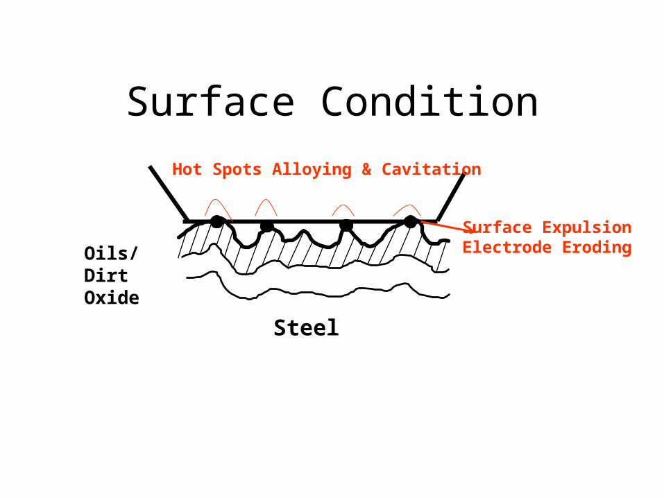
Surface Condition
Oils/Dirt Oxide
Steel
Hot Spots Alloying & Cavitation
Surface ExpulsionElectrode Eroding

Number of Welds
5K 10K 15K 20K
Elec
trod
e Fa
ceD
iam
eter
THICK SHEET - High Currents
THIN SHEETLower Current
Weld on ScaleScale Cleaned
Weld on Scale - No Upslope
With Upslope
Scale Cleaned
Effect of Surface Oxide on Electrode
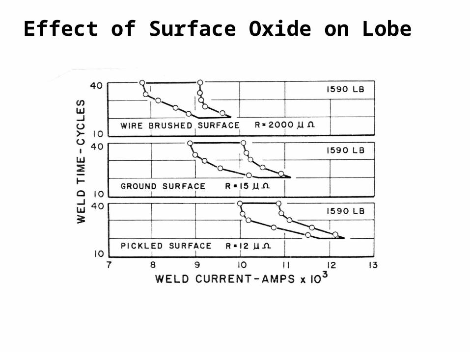
Effect of Surface Oxide on Lobe
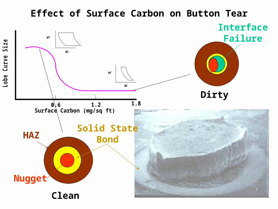
Effect of Surface Carbon on Button TearL
ob
e C
urv
e S
ize
Surface Carbon (mg/sq ft)
WC
WT
WC
WT
0.6 1.2 1.8Dirty
Clean
HAZSolid State
Bond
Nugget
InterfaceFailure
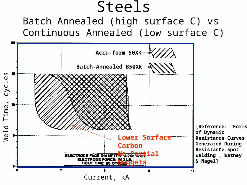
Weld Lobes of Two HSLA SteelsBatch Annealed (high surface C) vs
Continuous Annealed (low surface C)
Current, kA
We
ld T
ime,
cyc
les
[Reference: “Formsof Dynamic Resistance CurvesGenerated DuringResistance SpotWelding”, Watney& Nagel]
Accu-form 50XK
Batch-Annealed B50XK
Lower Surface CarbonNo Partial Nuggets

Turn to the person sitting next to you and discuss (1 min.):• What are some ways that a steel company can get cleaner steels both internally and on the surface?
Process Variables
Process Parameters:
• Weld Current
• Weld Time
• Hold Time
• Upslope/Downslope
• Pulsing
• Electrode Force
• Postweld Temper
• Electrode Designs
Material Parameters:
• Chemistry• Cleanliness• Surface Condition• Material Processing• Thickness
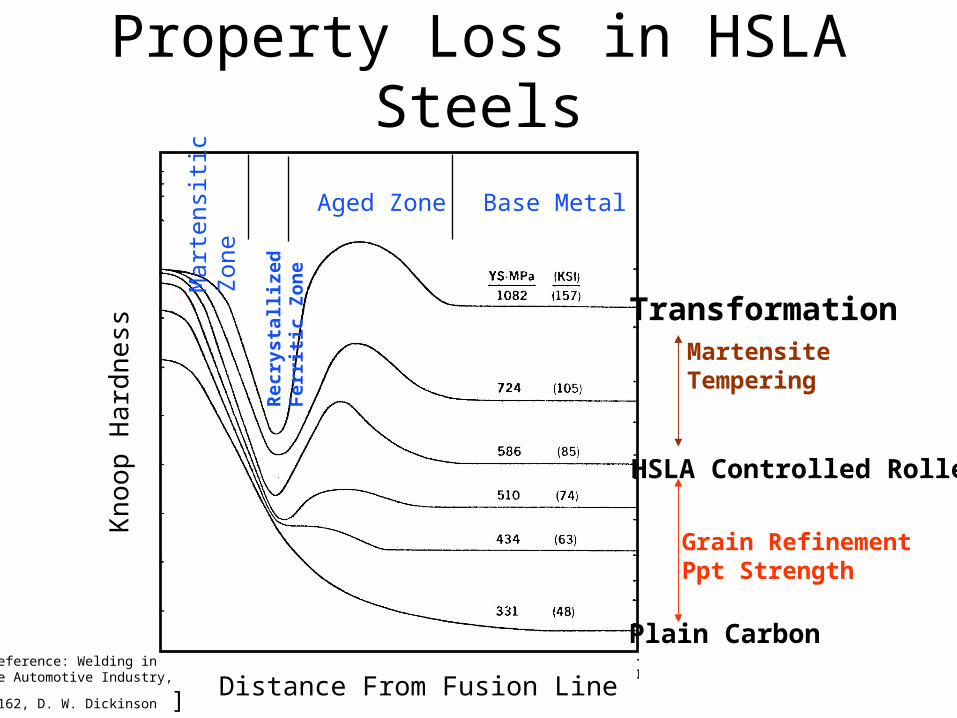
Heat-Affected Zone Property Loss in HSLA Steels
Kn
oop
Har
dn
ess
Distance From Fusion Line
Base MetalAged Zone
Rec
ryst
alli
zed
Fer
riti
c Z
on
e
Mar
tens
itic
Zon
e
[Reference: Welding inthe Automotive Industry,
p.162, D. W. Dickinson ]
Plain Carbon
HSLA Controlled Rolled
Grain RefinementPpt Strength
TransformationMartensiteTempering

Microstructure Near Outside Edge of HAZ in SRA Steel Spot Weld
[Reference: “Spot Weldability of High-Strength Sheet Steels”, WeldingJournal 59 (January1980), Baker & Sawhill]
Process Variables
Process Parameters:
• Weld Current
• Weld Time
• Hold Time
• Upslope/Downslope
• Pulsing
• Electrode Force
• Postweld Temper
• Electrode Designs
Material Parameters:
• Chemistry• Cleanliness• Surface Condition• Material Processing• Thickness
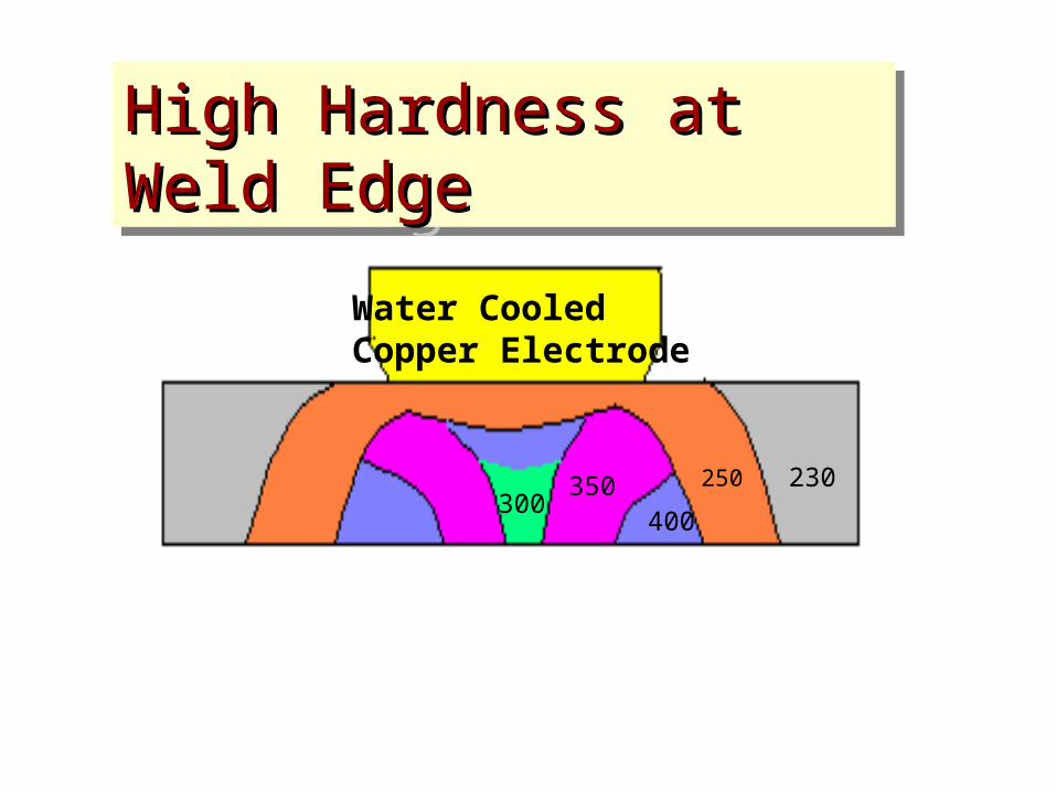
High Hardness at Weld EdgeHigh Hardness at Weld Edge High Hardness at Weld EdgeHigh Hardness at Weld Edge
230250
400350
300
Water Cooled Copper Electrode
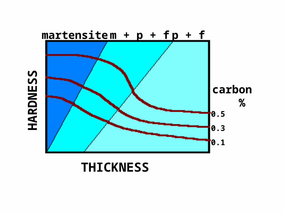
THICKNESS
HA
RD
NE
SS
martensite m + p + f p + f
carbon %
0.5
0.3
0.1
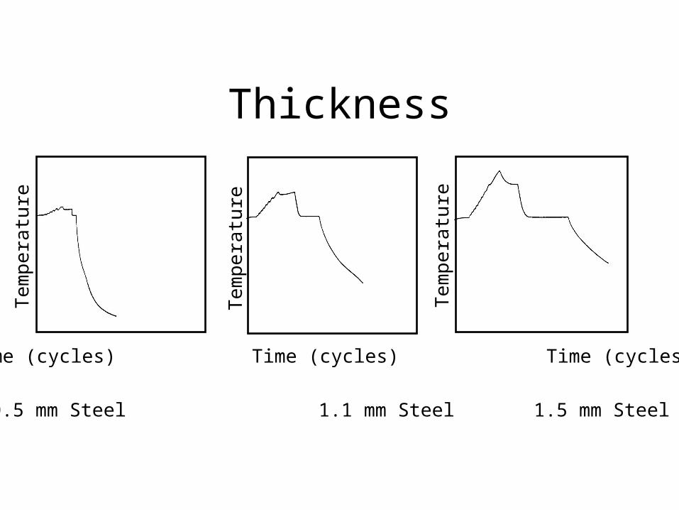
Thickness
Time (cycles) Time (cycles) Time (cycles)
Te
mp
era
ture
Te
mp
era
ture
Te
mp
era
ture
0.5 mm Steel 1.1 mm Steel 1.5 mm Steel
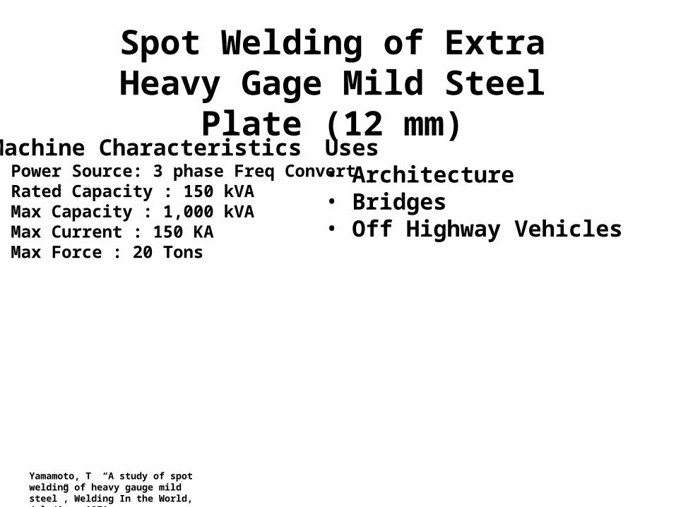
Spot Welding of Extra Heavy Gage Mild Steel Plate (12 mm)
Machine Characteristics• Power Source: 3 phase Freq Convert• Rated Capacity : 150 kVA• Max Capacity : 1,000 kVA• Max Current : 150 KA• Max Force : 20 Tons
Uses• Architecture• Bridges• Off Highway Vehicles
Yamamoto, T “A study of spot welding of heavy gauge mild steel”, Welding In the World, July/Aug, 1971
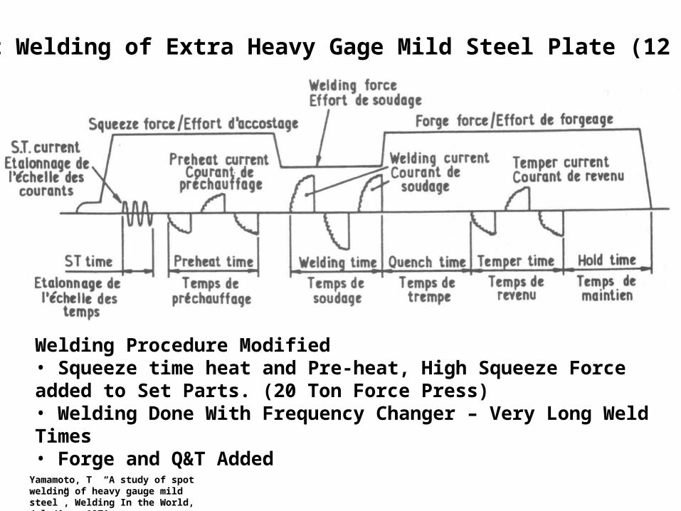
Spot Welding of Extra Heavy Gage Mild Steel Plate (12 mm)
Welding Procedure Modified• Squeeze time heat and Pre-heat, High Squeeze Force added to Set Parts. (20 Ton Force Press)• Welding Done With Frequency Changer – Very Long Weld Times• Forge and Q&T Added
Yamamoto, T “A study of spot welding of heavy gauge mild steel”, Welding In the World, July/Aug, 1971
Yamamoto, T “A study of spot welding of heavy gauge mild steel”, Welding In the World, July/Aug, 1971
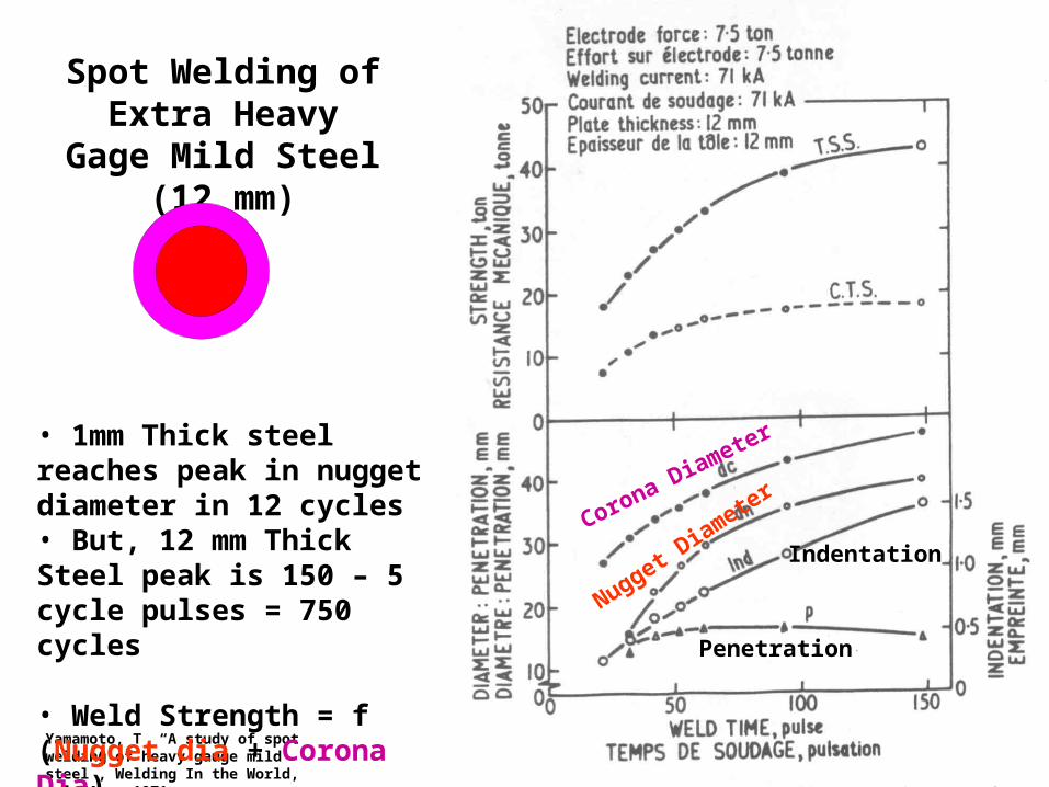
Spot Welding of Extra Heavy Gage Mild Steel (12 mm)
Corona Diameter
Nugget Diamete
r
Indentation
Penetration
• 1mm Thick steel reaches peak in nugget diameter in 12 cycles• But, 12 mm Thick Steel peak is 150 – 5 cycle pulses = 750 cycles
• Weld Strength = f (Nugget dia + Corona Dia)

Yamamoto, T “A study of spot welding of heavy gauge mild steel”, Welding In the World, July/Aug, 1971
Effect of Electrode Force on Spot
Welding of Extra Heavy Gage Mild
Steel (12 mm)
Increased Force• Reduces Nugget Diameter (lower R)• Almost no effect on Corona Dia• Only Slightly Lowers TSS
The Corona Diameter Plays a large Role in Strength of Very Thick Materials
>F
Spot Welding of Extra Heavy Gage Mild Steel (12 mm)
• The thermal time constant for 12 mm thick steel plate is remarkably high (10 sec. vs 1 mm at 0.1 sec)
• Increased electrode force leads to decreased heat
• The corona bond around the weld contributes a great deal to mechanical strength
• The incidence of blow holes or shrinkage cavities decreases as electrode force increases
Yamamoto, T “A study of spot welding of heavy gauge mild steel”, Welding In the World, July/Aug, 1971
Turn to the person sitting next to you and discuss (1 min.):• What factors might limit the thickness of shet or plate steel that can be spot welded?
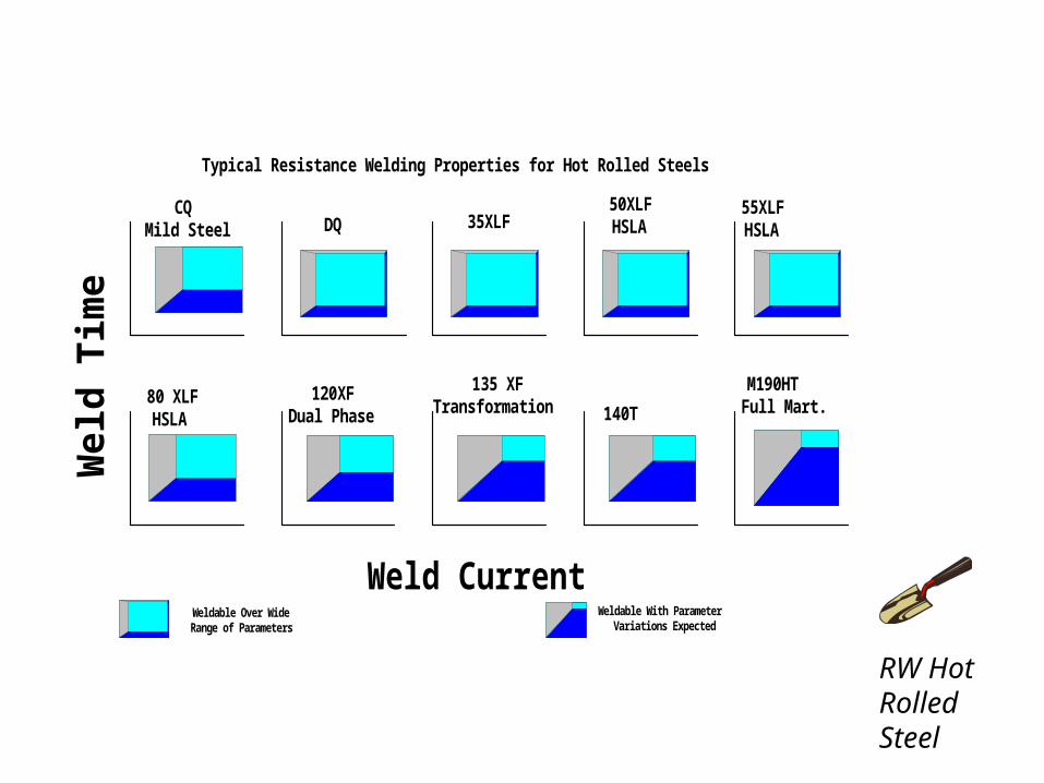
Weld Current
Wel
d T
ime
CQMild Steel DQ 35XLF
50XLFHSLA
55XLFHSLA
80 XLFHSLA
120XFDual Phase
135 XFTransformation 140T
M190HTFull Mart.
Weldable Over WideRange of Parameters
Weldable With ParameterVariations Expected
Typical Resistance Welding Properties for Hot Rolled Steels
RW Hot Rolled Steel
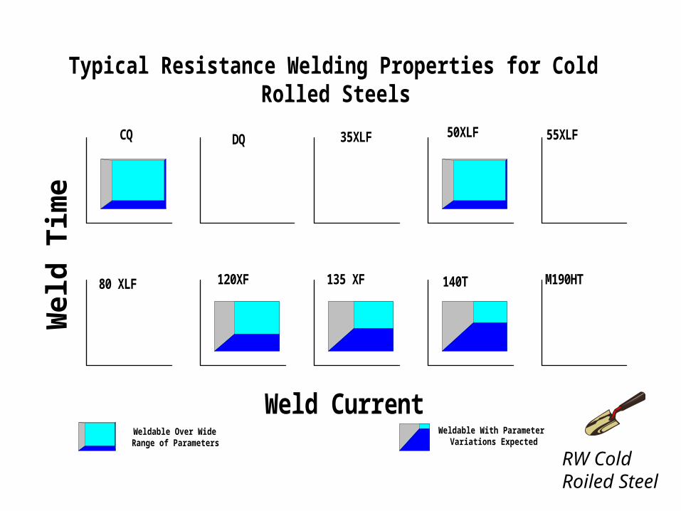
Weld Current
Wel
d T
ime
CQ DQ 35XLF 50XLF 55XLF
80 XLF 120XF 135 XF 140T M190HT
Weldable Over WideRange of Parameters
Weldable With ParameterVariations Expected
Typical Resistance Welding Properties for ColdRolled Steels
RW Cold Roiled Steel
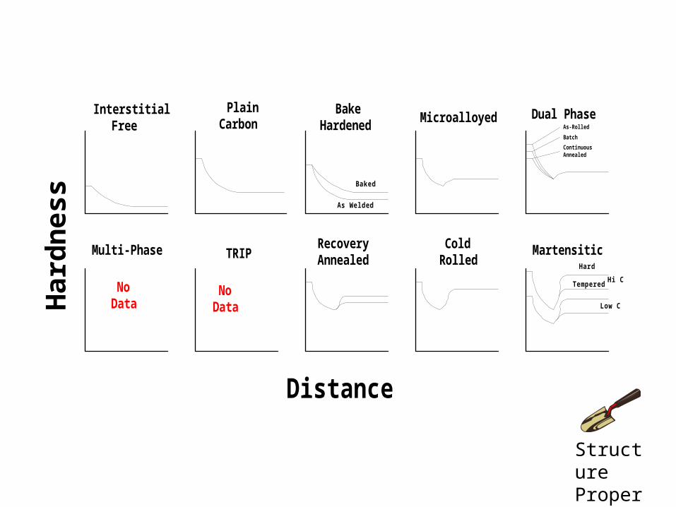
Distance
Har
dn
ess
InterstitialFree
PlainCarbon
BakeHardened
Microalloyed Dual Phase
Multi-Phase TRIPRecoveryAnnealed
ColdRolled
Martensitic
As Welded
Baked
Hard
TemperedHi C
Low C
NoData
NoData
As-Rolled
Batch
ContinuousAnnealed
Structure Property