Embed Size (px)
Citation preview
NASA Technical Memorandum 103892
Performance of Uncoated AFRSI
Blankets during Multiple SpaceShuttle Flights
Paul M. Sawko and Howard E. Goldstein
April 1992
(NASA-TM-IO3892) PERFORMANCE OF UNCOATEDAFRSI _LANKETS nURING MULTIPLE SPACE SHUTTLE
FLIGHTS (NASA) 36 p
G3/Z5
N92-29104
Unclas
0108039
National Aeronautics andSpace Administration


NASATechnicalMemorandum103892
Performance of Uncoated AFRSI
Blankets during Multiple SpaceShuttle FlightsPaul M. Sawko and Howard E. Goldstein, Ames Research Center, Moffett Field, California
April 1992
National Aeronautics andSpace Administration
Ames Research CenterMoffett Field, California 94035 -1000

Summary
Uncoated Advanced Flexible Reusable Surface Insulation
(AFRSI) blankets were successfully flown on seven con-
secutive flights of the Space Shuttle Orbiter OV-099
(Challenger). In six of the eight locations monitored
(forward windshield, forward canopy, mid-fuselage, upper
wing, rudder/speed brake, and vertical tail), the AFRSI
blankets performed well during the ascent and reentry
exposure to the thermal and aeroacoustic environments.Several of the uncoated AFRSI blankets that sustained
minor damage, such as fraying or broken threads, could
be repaired by sewing or by patching with a surface coat-
ing called C-9. The chief reasons for replacing or com-
pletely coating a blanket were fabric embrittlement andfabric abrasion caused by wind erosion. This occurred in
the orbiter maneuvering system (OMS) pod sidewall and
the forward mid-fuselage locations.
Acronyms
AFSRI Advanced Flexible Reusable Surface
CVD
DFRF
FRSI
HMDS
HRSI
KSC
LE
LH
LRSI
OEX
OML
OMS
RCC
RH
TE
TPS
Insulation
chemical vapor deposition
Ames-Dryden Flight Research Facility
Felt Reusable Surface Insulation
hexamethyldisilane
High-Temperature Reusable Surface Insulation
Kennedy Space Center
leading edge
left-hand
Low-Temperature Reusable Surface Insulation
Orbiter Experiments (Program)
outer mold line
orbiter maneuvering system
reinforced carbon/carbon
right-hand
trailing edge
thermal protection system
Introduction
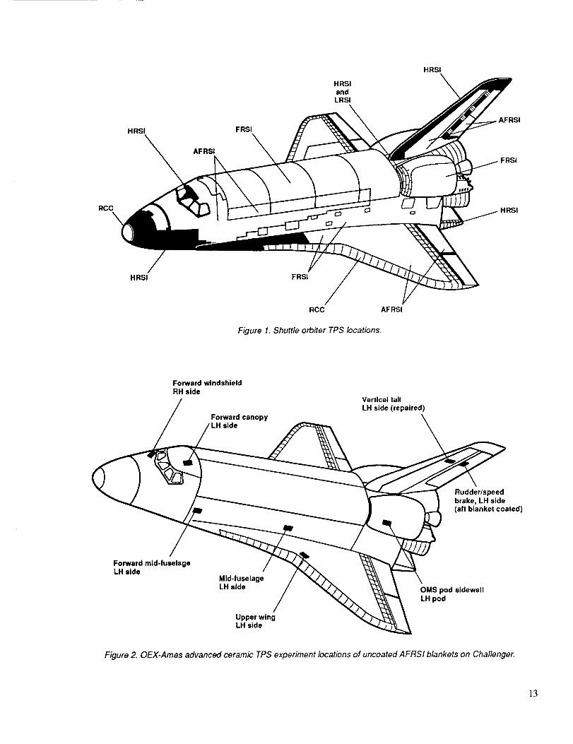
A quilted, flexible ceramic insulation blanket calledAdvanced Flexible Reusable Surface Insulation (AFRSI)
has replaced about 6,000 white ceramic tiles (LI-900) as
the thermal protection system (TPS) in a variety of loca-
tions on the Space Shuttle vehicles (fig. 1). The blankets
were installed on surface areas where temperatures gen-
erally do not exceed 1200 ° F. The AFRSI has been certi-
fied to cover sections of the fuselage, upper wing, cargo
bay door, vertical stabilizer, speed brake, elevon cove, and
orbiter maneuvering system (OMS) pod. The total acreageinstalled amounts to over 4,000 ft 2 on each of the four
Shuttle vehicles.
AFRSI is constructed from silica batting sandwiched
between layers of silica fabric and glass fabric sewn
together with Teflon-sized silica thread in a l-in. stitch
pattern (refs. 1-3). The silica fabric surface is the outermold line (OML) surface and is exposed to the Shuttle
aerothermal environment of ascent and reentry. The cur-rent version of AFRSI has a silica OML surface coated
with a thin ceramic material called C-9 coating, to reduce
degradation caused by the aerodynamic forces during
flight (ref. 4).
The OML surface of AFRSI was initially intended to be
uncoated. In fact, the original AFRSI used in both arcjetand wind tunnel tests was uncoated. The use of AFRSI as
a TPS for the Space Shuttle evolved from the ground-based qualification tests to the initial installation of about30 ft 2 in the elevon cove section of the OV-099 vehicle
(Challenger). After several successful flights, a decision
was made to expand the use of AFRSI by replacing some
of the LI-900 white tiles located on the left OMS pod with
uncoated AFRSI. This was done for Flight STS-6 of
Challenger. Postflight examination of the AFRSI deter-
mined that serious damage had occurred on ten blankets,
with major loss of the OML fabric on an additional twentyblankets (ref. 4). The next Challenger flight, STS-7,
resulted in fabric and batting damage to the right OMS
pod. However, it was determined from postflight inspec-
tion and analysis that the OML fabric damage was not
caused by the high-energy vortex impingement that
apparently caused the severe damage to the AFRSI blan-
kets installed on the left OMS pod for STS-6. The dam-
aged AFRSI blankets on the right OMS pod resulted from
a water spray boiler malfunction, which released a largeamount of water from a vent situated in the forward crotch
region near the vertical tail. This caused ice and water to
hit the AFRSI during reentry. This was verified from in-
orbit photos showing ice formation in the damaged area.Because temperatures did not exceed 1200 ° F for these
two flights, it was postulated that aerodynamic, rather
than thermodynamic, effects caused the damage to the
AFRSI on the left OMS pod during STS-6. Future flights
were scheduled to reach higher temperatures, which could
accelerate damage when combined with the aerodynamicforces.

AsaconsequenceofthedamagetotheAFRSIblanketslocatedonbothOMSpodsofChallenger,allAFRSIblanketswerecoatedwiththeC-9coating.TheC-9coat-ingwastested,qualified,andsuccessfullyflownonfourChallengermissions.Duringthistimeover4,000ft2ofAFRSIwereinstalledonanotherShuttleorbiter,Discovery,replacingabout6,000oftheLI-900whitetiles.TheC-9coatingwasusedontheAFRSIblanketsonDiscoveryaswellasonChallenger.
Aproposalwasmade,however,tokeepsomeChallengerblanketsuncoatedinordertoevaluatetheperformanceofAFRSIinlocationsotherthantheOMSpod,becausetheOMSpodgeneratedunusuallyenergeticflowconditionsdissimilartomostsurfacesonaShuttlevehicle.A deci-sionwasmadetomonitortheperformanceofuncoatedAFRSIatvariouslocationsonChallenger,aspartoftheongoingOrbiterExperiments(OEX)ProgramonChallenger.TheuncoatedblanketswereincorporatedintotheAdvancedCeramicTPSExperimentpackageoftheOEX.Forthisprogram,experimentsareflownonaShuttleorbitertogainaerodynamic,aerothermodynamic,andmaterialsdatanotpossibletoobtainfromground-basedexperiments.TheobjectiveofthispaperistodescribetheperformanceofuncoatedAFRSIblanketsateightlocationsonChallengerduringsevencompletedflights.Thefollowingweretheprogram'sgoals:
1. Evaluatelong-termdurabilityinbothflightandgroundenvironments
2. Determinefailuremodesasafunctionofspecificenvironment,relatedtotheAFRSIlocationonthevehicle
3. Developrepairandreplacementcriteria4. Evaluaterepairmethodsanddurability
TheauthorswishtoacknowledgethediligenteffortsofthepersonneloftheSpaceTransportationSystemsDivi-sionofRockwellInternationalwhoobtainedtheinspec-tiondatafortheOEXProgramunderNASAContractNAS9-17244.
Experimental Setup
Location of Uncoated AFRSI Blankets on Challenger
For flight testing, eight locations on the Challenger
exterior were selected for comparing the performance ofuncoated AFRSI with C-9 coated AFRSI. These eight
locations are shown in figure _,"_a schematic view of the
Shuttle. The locations were
1. Forward wind._hield, right-hand (RH) side
2. Forward canopy, left-hand (LH) side
3. Forward mid-fuselage, LH side
4. Mid-fuselage, LH side
5. Upper wing, LH side
6. OMS pod sidewall, LH pod
7. Vertical tail, LH side
8. Rudder/speed brake, LH side
These locations provided a range of aerodynamic andthermal environments over the vehicle from front to rear.All locations were on the left-hand side of the vehicle
except for the windshield location, which was on the
right-hand side. The AFRSI blankets were installed in
coated/uncoated pairs ira six of the eight locations. Theforward windshield and the OMS pod sidewall locations
each had one uncoated blanket only.
Inspection Criteria for Uncoated AFRSI Blankets
The uncoated AFRSI blankets were fabricated, water-
proofed, and mounted according to specified procedures.Before being incorporated into the OEX Program, these
uncoated blankets were installed and endured four flights
(STS-8, 41 B, 41 C, and 41 G) without OEX performancedocumentation, because at that time the C-9 coated
AFRSI blankets were being certified for flight use. When
the uncoated AFRSI blankets became part of the OEX
Program, it became necessary to develop an inspection
program to monitor their in-flight performance as a TPS.
A specification was established for the preflight and
postflight inspection of the uncoated AFRSI blankets on
Challenger. The inspection process was to remain in
effect for 12 flights and provided the following:
1. Documented preflight and postflight inspections con-
ducted by visually examining each installed blanket for
fabric damage, thread damage, blanket distortion, and dis-
coloration, and by manually examining each blanket for
feel (stiffening)
2. Preflight and postflight color photographs of theblankets
3. Flight history of the ascent and reentry environments,including such data as heating in the blanket locations,
noise levels in the blanket locations, angle of attack, flight
anomalies (such as flights through rain or ice), blanket
anomalies, and side slip

4. Surfacereplicamapsof each uncoated AFRSI blan-ket to mark locations of damage or change, and to quan-
tify the type and amount of damage or change
5. A summary report that included the above data alongwith a short narrative of the flight history
Fabric damage was defined as fraying, cuts, and lost or
missing fabric or batting. Thread damage was considered
to be any broken thread, loose thread, or missing thread.Blanket distortion was defined as gaps between blankets,
puckering, pillowing, or batting movement involving a
change of position, thickness, or density. Discoloration
was any visual display of staining, marking, or fading.Feel was a subjective determination using touch to clas-
sify stiffness or embrittlement. However, embrittlementcould be accurately judged only by physically pushing onthe blanket fabric surface, so this test was performed only
if a blanket was to be replaced.
Thermal Environment
The maximum surface temperatures reached at each of the
eight locations is summarized in table 1; ascent and
reentry temperatures are listed separately. As expected,
the ascent temperatures were much lower, with the lowest
temperatures occurring in the canopy, followed by the
fuselage locations. All ascent temperatures were below700 ° F. All locations experienced higher surface tempera-
tures during reentry because of aerodynamic heating. Themaximum reentry temperature measured was slightly
above 1200 ° F, in the upper wing location.
Aeroacoustic Environment
The peak aeroacoustic levels (expressed in decibels) wereobtained from the noise profiles recorded in the generallocations of the uncoated AFRSI blankets. These aresummarized in table 2 for both ascent and reentry. Greater
pressures always occurred during the ascent phase of aShuttle flight, with the canopy location experiencing the
highest noise level: 163 dB.
Flight Performance of Uncoated AFRSI
The following discussion summarizes the flight perfor-mance of the uncoated AFRSI through seven consecutive
flights of the Challenger vehicle. The eighth flight (51C)ended in the tragic destruction of Challenger and crew,
terminating this activity. Performance is reported in two
related phases. In the first phase, damage inspectionresults were obtained from the normal postflight TPS
assessment conducted at Kennedy Space Center (KSC)
after each Shuttle flight; the results from the four
Challenger flights before AFRSI testing was incorporatedinto the OEX Program (Flights STS-8, 41B, 41C, and
41G) were included in this phase and are summarized in
table 3. In the second phase, the flight performance of thesame blankets was determined by using the more detailed
criteria established under OEX guidelines. All inspections
were done after the landing at Ames-Dryden Flight
Research Facility (DFRF). Tables 4, 5, and 6 summarize
the results of the damage inspection for uncoated AFRSI
for the three flights conducted under the OEX Program
(51B, 51F, and 61A).
"Close up" visual examination of the blanket surfaces dur-
ing the OEX inspection conducted at DFRF was pre-
vented by post-landing procedures and the preparation ofthe Shuttle for return to KSC; the inspections were per-
formed at distances ranging from 2 to approximately 30 ft.Binoculars were used where needed. This caused prob-
lems with data gathering and interpretation. Specific dam-
age details, such as individual broken threads and minorareas of abraded fabric, might have been overlooked dur-
ing the DFRF examination because of the restrictedaccess. Sunlight and shadows on the white blanket surfacealso caused some visual inconveniences. Finally, the
effect of the terry flight to KSC after each landing atDFRF could not be accurately determined because of the
problems with the inspection before the ferry flight.
The flight performance of the blankets in the individuallocations is discussed below.
Forward Windshield
No data were recorded tbr STS-8, but postflight visual
inspection after the next flight, 41B, showed that theblanket had sustained some minor fraying of the surface
fabric along the leading edge (table 3). A similar observa-
tion was noted for Flights 41C and 41G, with no further
progression of fabric fraying. After 51B, some additionaldamage in the form of broken threads was noticed and
some yellow discoloration was evident, but there was nodistortion. After 5 IF, damage had progressed to a small
area of missing fabric at the leading edge plus some torn
fabric along the trailing edge. These damaged blanket
sections were repaired with C-9 coating before the next
flight. This is shown in the preflight photograph in fig-
ure 3(a). Flight 61A, the last completed flight in the OEXseries, showed the C-9 coating repairs responding well to
the thermal and acoustic environment, since no new
damage was evident. The photograph in figure 3(b), takenafter the landing at DFRF, demonstrates that a blanket can
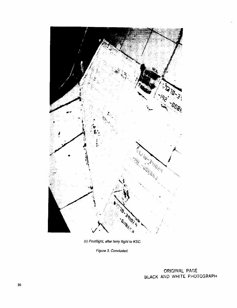
be repaired with C-9 coating. Figure 3(c) is a postflight
photograph taken at KSC and shows no further change
after the ferry flight to return Challenger to KSC. Note
that the square patch in the upper right corner survived
thisflight,whichshowsthatpatchrepairscanbemadetoanindividualblanket.Also,nofurtherdiscolorationorsurfacedistortionoccurred.
ForwardCanopyTheoverallconditionofthetwoblanketslocatedherewasexcellentaftersevenflights.Nofabricorthreaddamagewasobserved.Theonlychangeswereaslightpillowingwithinsulationmovementatthetrailingedge,seenafterFlights51Band51F,andsomeminordiscolorationofbothblanketsfromtheredsiliconeadhesive(RTV560)usedtoattachtheblankets.ThephotographicrecordofFlight61Asupportstheseobservations.Figure4(a)isthepreflightandfigure4(b),thepostflightphotographtakenatDFRF;figure4(c)isthefinalpostflightphotographtakenatKSCafterthereturnferryflightviathemodifiedBoeing747aircraft.Thislocationisexposedtothehigh-estpeakacousticlevels,duringbothascentandreentry,ofanyoftheeightlocations(seetable1).
ForwardMid-Fuselage
Two uncoated blankets were placed in this area. Blan-ket 391142-015 had one broken stitch after STS-8, and the
other blanket, 391142-016, incurred no damage. No data
were reported for the next two flights, 41B and 41C, for
either blanket. Subsequently, inspection after Flight 41G
revealed a gray-brown discoloration over small areas of
the blanket surfaces. No distortion was evident. Missing
stitches (threads) and fraying of a corner of the leading
edge were seen after Flight 51B on Blanket 391142-015;
Blanket 391142-016 had evidence of missing stitches on
the trailing edge. The edge surface of both blankets still
appeared grayish, and there was still no distortion of
either blanket surface. Some sewing repairs of Blan-ket 391142-015 were done at this time.
After the postflight examination for Flight 5 IF, Blan-
ket 391142-015 was replaced with a new AFRSI blanket,
also uncoated. This replacement was necessary for tworeasons. First, the removal of a small section of each
blanket revealed a deleterious change in the condition of
the silicone rubber heat sink underneath. (See the section"Vertical Tail" for more details.) The second reason was
fabric embrittlement, which made any repair of the
blanket impossible because of the handling required. This
was the first time fabric embrittlement was noticed in any
of the eight locations since it could only be determined byphysically handling the blanket.
Visual inspection of the newly installed Blanket 391142-
015 after Flight 61A showed fabric damage in the form ofan abraded surface in the center of the blanket, as well as
some loose stitches. The adjacent blanket also had an
abraded fabric surface and broken threads, indicating thatminor wind erosion had occurred. This is shown in the
postflight photographs in figure 5(a), taken after the
landing at DFRF, and figure 5(b), taken after the ferry
flight return to KSC. A preflight photograph, figure 5(c),is provided for comparison. The blankets were left
unrepaired to permit continued evaluation.
Mid-Fuselage
Two blankets were evaluated in this location. The inspec-
tions for the first tour flights (table 3) indicated no pro-
gressive damage from wind erosion or physical distortion
of either test blanket. Some minor damage in the form of a
small OML tear was reported for Blanket 391142-017
after STS-8, but no data were gathered for the next threeflights. Usually this means that no new evidence of dam-
age was obvious. For Blanket 391142-018, minor frayingon the forward edge was reported after STS-8, no data
were gathered after 41B. the same frayed forward edgewas noted after 41C. and some peeling of the blanket on
this forward edge was reported after 41G. This peeling
was probably caused by a poor adhesive bond between thesilicone heat sink and the silicone adhesive.
The blankets showed no new damage after Flight 51B
(with which began the more detailed inspection of the test
blankets under the OEX Program), although some slight
discoloration on the surface was apparent. After
Flight 5 IF (documented in table 5), damage was observedfor both blankets; several broken threads were evident
along with the discoloration noted from the previous
flight, and some minor distortion was noted in the form of
a plus or positive step at the corners of both blankets.
After Flight 61A (reported in table 6), no further changewas observed in blanket damage or appearance.
The photographic evidence supports these observations.
Figure 6(a), the preflight photograph, and figure 6(b), the
postflight photograph, appear similar, with a few broken
threads near the patched section. Furthermore, no observ-
able damage occurred during the return ferry flight to
KSC from DFRF (fig. 6(c)). Overall, the blanket perfor-
mance in the mid-fuselage location can be considered
excellent since no progressive damage occurred. The peakacoustic levels (table 2) reached in this location, the low-
est for the eight locations studied, combined with the
modest surface temperatures shown in table I, contribute
to a benign aerodynamic environment for these uncoatedAFRSI blankets.
Upper Wing
The upper wing location had two test blankets. The post-
flight TPS assessment (summarized in table 3) reported no
damageafterSTS-8foreitherBlanket195056-001or195056-002.Nodatawereacquiredfortheadditionalthreeflightsthatwerepartofthisphase.TheFlight51BpostflightinspectionrevealedonlyasmallfrayedareaonBlanket195056-001,butnodiscolorationorblanketdis-tortionwasapparent.Nodamageordiscolorationwasobservedforthesecondtestblanket,195056-002,althoughapositivestepontheleadingedgewasnoted.AsmallC-9coatingrepairwasneededintheleadingedgearea.AfterFlight5IF,nonewdamagetoeitherblanketwasfoundandtherewasnochangeinthepositivestepdistortionofBlanket195056-002,butadarkgraycolorwasobservedonthesurfaceofbothblankets.
AfterFlight51F,bothblanketswerereplacedwithnewuncoatedAFRSIblanketseventhoughtheoriginalblan-ketswereinexcellentconditionaftersixflights.Thiswasnecessarybecausethesiliconerubberheatsinkunder-neaththeblanketsrevertedtoasoftandtackystate.(Seethesection"VerticalTail"formoredetails.)
ThepostflightinspectionofFlight61A,asexpected,revealednodamage,discoloration,ordistortion.ThisisdocumentedbythepreflightandpostflightphotographsoftheAFRSIblanketsontheupperwing(figs.7(a)and7(b),respectively).TherewasnopostlandingphotographtakenatDFRFforthislocation.It shouldbementionedthatthislocationhadthehighestsurfacetemperature(about1235° F)ofanyoftheeightlocations.
OMS Pod Sidewall
Only one blanket was used at this location, and no data
were reported for the four flights inspected under the
postflight TPS assessment (table 3). However, the OEXpostflight inspection for Flight 5 IB (table 4) revealed thatthe blanket was C-9 coated and therefore not a valid test
blanket. Monitoring of this location was discontinued and
no photographs were taken for documentation. The coated
blanket may have been installed after the severe damageto the uncoated AFRSI during STS-6, discussed in the
Introduction, and the mistake was probably not caught
earlier because of the difficulty in close up inspection at
DFRF.
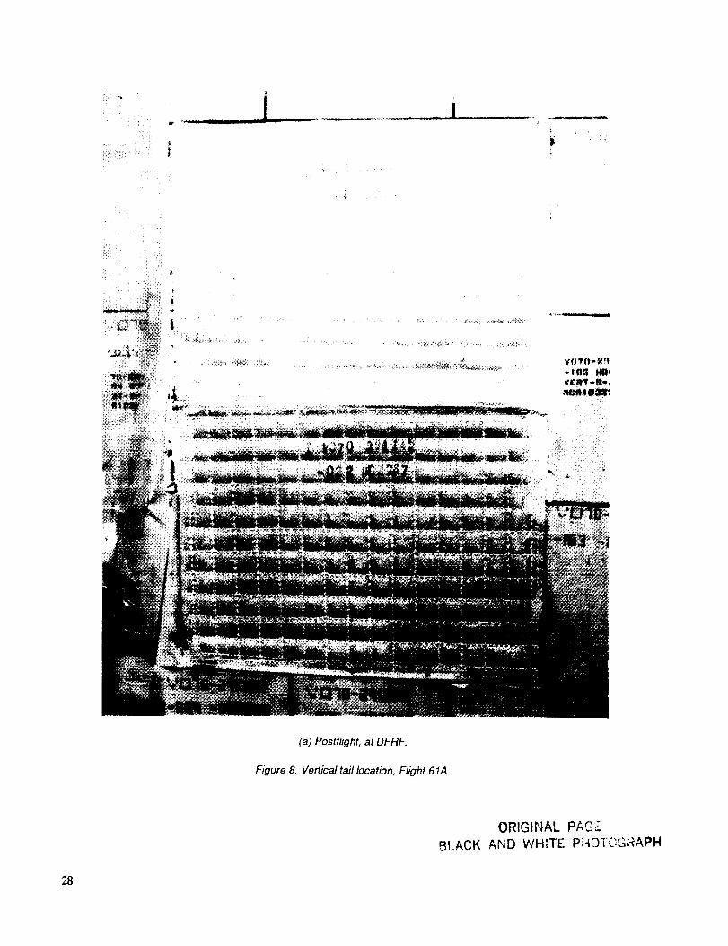
Vertical Tail
Two blankets were placed in the vertical tail (stabilizer)
area; blanket inspections for the first four flights, reported
under the postflight TPS assessment, are summarized intable 3. Blanket 391142-028 showed no damage after
these flights, and Blanket 391142-021 showed only minor
damage, indicated by minor fraying plus one broken
stitch, only after Flight 4lB. However, after Flight 5 IB(table 4), it was obvious that both blankets had suffered
abraded surface fabric (OML) damage. The damage was
judged identical to that which occurred in ground-basedwind tunnel tests during AFRSI development; in thesetests, wind erosion was the primary source of damage.
After Flight 51 F, it was determined that both test blankets
had suffered progressively severe damage (table 5); theOML fabric was heavily frayed and some insulationmaterial was lost. It was concluded that these blankets
were degraded beyond repair either by patching or by C-9
coating, so the blankets were replaced. The replacementblankets were left uncoated to allow for continued
monitoring under the OEX Program.
After removal of both vertical tail blankets, it was
observed that the 0.25-in.-thick silicone rubber (RTV 560)heat sink installed beneath them had reverted to a soft and
tacky material. A Shore A hardness of 5 to 10 was mea-sured; a nominal hardness of 50 is typical for siliconerubber in the cured state. The extra thickness of silicone
rubber was supposed to function as a fail-safe layer ofinsulation in the event of a catastrophic failure of the
uncoated AFRSI test blankets during launch or reentry.
Since all the test blankets in all eight locations had been
installed over the heat sink layer, a 3-in.-square core sam-
ple was removed from one blanket in each area so thecondition of the heat sink material could be determined.
All the other heat sink locations were found to be within
an acceptable Shore A hardness range except tbr the heatsinks located under the blankets on the upper left wing
and one of the blankets at the forward mid-fuselage. Since
that heat sink material had reverted similarly to the heat
sinks under the vertical tail, the upper wing blankets were
also replaced. After some investigation, the silicone rub-ber reversion was attributed to the injection of the water-
proofing compound hexametbyldisilane (HMDS) during
the postflight rewaterproofing process. (The postflight
waterproofing history is shown in table 7.) Consequently,
starting with Flight 61A, postflight rewaterproofing usingHMDS was discontinued for those blankets covering heat
sinks.
After Flight 61A, the first flight of the newly installed
blankets, no new damage was visible (table 6), although
some minor discoloration was present at the leading edge
of Blanket 391142-021 and the upper edge of Blan-ket 391142-028. The blankets were discolored because the
silicone adhesive used during the installation process
(RTV 560) was exposed to a peak reentry temperature of888 ° F. This discoloration is seen in the photographs
taken after the landing at DFRF (fig. 8(a)) and the return
to KSC (fig. 8(b)), which revealed no damage other thanthe discoloration described when compared with the
preflight photograph (fig. 8(c)).

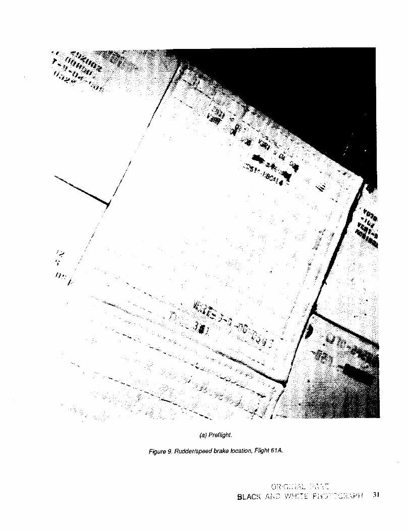
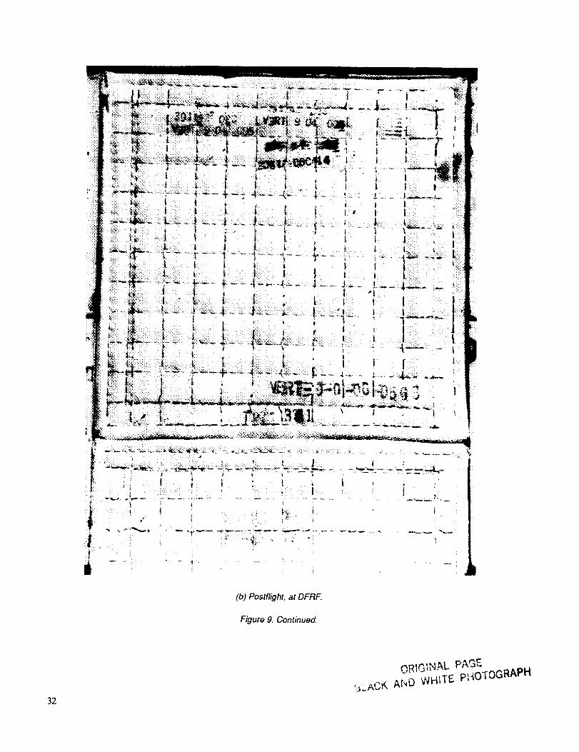
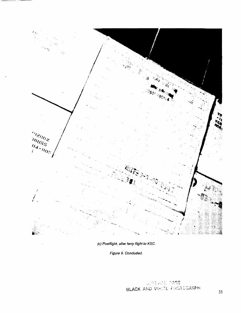
Rudder/Speed Brake
Initially, two uncoated AFRSI blankets were positioned at
this location. After STS-8, no data were reported foreither blanket (table 3). After the next flight, 41B, thedamage inspection showed a small tear in the OML fabric
along with several broken stitches for Blanket 391142-
023. The other test blanket, 391142-024, was C-9 coated
because of overall damage to the surface in the form of
broken threads and frayed fabric, so no further perfor-mance data were collected for this blanket. No new dam-
age was noticed for Blanket 391142-023 after Flights 41Cand 41G. After Flight 51B, there were no new broken
stitches, although some pillowing and insulation (felt)
movement at both the leading and trailing edges were
observed. No surface discoloration had occurred. Damageinspection after Flight 5IF showed no proliferation of
broken threads, no discoloration, and no change in the
degree of distortion from the previous flight. The
Flight 61A inspection revealed a slightly frayed corner at
the lower forward edge in addition to the original thread
breakage. Some black coloring of the sewing threads was
noticed. No further change in original distortion was
apparent. The overall condition of the remaining uncoated
AFRSI blanket was excellent. Again, a preflight photo-
graph was taken prior to Flight 61A (fig. 9(a)), and post-flight photographs were taken at DFRF and KSC
(figs. 9(b) and 9(c), respectively).
Concluding Remarks
The uncoated AFRSI blankets functioned well in six of
the eight locations selected for evaluation. The replace-ment and repair requirements for each location are
summarized in table 8. At only two locations, the vertical
tail and the forward mid-fuselage, did the blankets suffer
enough damage to require replacement. Both vertical tail
blankets had severely abraded fabric plus missing threads
and insulation, probably because of wind erosion;
comparable damage occurred in ground-based wind
tunnel simulations conducted during AFRSI development.One forward mid-
fuselage blanket, although showing no damage when itwas visually inspected, was found to have embrittled fab-
ric when it was removed because of the degradedcondition of the underlying silicone heat sink.
Two locations, the OMS pod sidewall and the rudder/
speed brake had one blanket each fully coated with the
C-9 coating because of programmatic decisions.
In summary, the following statements can be made:
1. Uncoated AFRSI blankets can survive at locations on
the vehicle that experience a range of thermal and acous-tic exposures during ascent and reentry.
2. Two types of major failure requiring blanket
replacement occurred: abraded fabric surface caused bywind erosion, and fabric embrittlement.
3. Uncoated AFRSI blankets can be repaired by sewing
and by the selective application of C-9 coating.
References
1. Sawko, P. M.: Effect of processing treatments on
strength of silica thread for quilted insulation on
Space Shuttle. SAMPE Quarterly, vol. 16, no. 4,
July 1985, pp. t7-21.
2. Goldstein, H.; Leiser, D.; Sawko, P. M.; Larson,
H. K.; Estrella, C.; Smith, M.; and Pitoniak, F.:
Insulation blankets for high-temperature use.NASA Tech Brief 11453, Ames Research
Center, vol. 9, no. 4, Winter 1985.
Trujillo, B. M.; Meyer, R. M., Jr.; and Sawko, P. M.:
In-flight load testing of advanced Shuttle thermal
protection systems. AIAA Paper 83-2704, Nov.1984.
Mui, D.; and Clancey, H. M.: Development of a pro-tective ceramic coating for Shuttle orbiterAdvanced Flexible Reusable Surface Insulation
(AFRSI). Ceramic Eng. and Sci. Proc., vol. 6,
no. 7-8, July-Aug. 1985, pp. 793-805.
.
4.

Table 1. STS-5 IB Uncoated AFRSI thermal environment
Blanket location Maximum surface temperature, °F
Ascent Reentry
Forward windshield, RH 576 605
Forward canopy, LH 316 399
Forward mid-fuselage, LH 347 742
Mid-fuselage, LH 347 675
Upper wing, LH 574 1234
OMS pod sidewall, LH 681 709
Vertical tail, LH 487 888
Rudder/speed brake, LH 478 759
Table 2. STS-51B Peak ascent/reentry acoustic environment
Blanket location Peak acoustic level, dB
Ascent Reentry
Forward windshield, RH 153 146
Forward canopy, LH 163 156
Forward mid-fuselage, LH 156 146
Mid-fuselage, LH 150 142
Upper wing, LH 150 145
OMS pod sidewall, LH 156 152
Vertical tail, LH 155 145
Rudder/speed brake, LH 158 146

r"
E:=
L_
r,,,r_
©
b
EE=
0
¢,.)
E
[...,
_b
8
¢2
t--,
d
,r-
¢3
o
v,,r-
L_
OlOi
[.-
E
oz
• o
O0 == E
_ _ ZZ z
_b
e_ 0 0 0 0 0 _ 0 0 0
ZZ ZZ Z _ ZZ Z
©0 ©0 O0 O© 0
ZZ zz ZZ ZZ Z
0
Z
_b
_Ee- -1_
o o
zZ
0 0
zz
e-
_a
e-_2
o
e.-o
c-
r-
E
_2i'-
0
z
E
t-
o
z
_2
g_
•,_ ,-,
d
c_
0
Z
O
Z
¢.,,
_5¢..
oo =o _ _ oo o oo o oZZ OZ O_ ZZ Z Z_ Z Z
-F, _ _,F, "_- =-- _- -
u. u. _ :D 0 >
II
,-1

°_
u..
u.<
0oe-
EE
c-O
c_
E
Xu_©
r_
0
Z
.o
© 0
L_
f-
0
E
6
u_
E
0
u_
©
0 0
ZZ
L_L3
0 0
ZZ
e- e._
o
r_
z_e- t-- _-.o 0 0
Z Z Z
u_
0 © .... 0 0
zz _ zz
©
0 0 0 © 0 0
ZZ Z Z Z Z
u_Z
©
E
"T'o.
o&
©
m < m
© ;>
.1

e-
e-
_a%
me
<"0
0
e",
EE
.o
e..
¢-j
E
uJ©
e-.
.o$-.
o
c-O
oo
_0
E
6
r-.
.o
o
r'-
c-O
Z
oZ
e-
E
m"
o
a_
E0
e- e'.
o o
o
>
oZ_
ZZ
,=F:
e- ¢-
e-
e_= em
e- e..-
0 0
ZZ
_5
_- _-_.7. "E_-_- -_--
u. u. u.
0 0 0 ©
ZZ Z Z
e-
°_
_ _. .-
E
e-. r"
"0 '_
0 0 _ZZ m m
_0,I oO
_ ',.1_ ',0 _0,1 0,1
0
Z
_ t'¢3
e-, ¢-
I1,,,,
I0

<
_f3
r23
<
0
bEE
,r....0
'5
C,.O
E
Xu.30
,,6
[..,
c:
£1=0
,m
©
I,-.
0
ut_
C_
_4b
E
Z
...'Z
U3[.--
,,..,
©
_E
0
Z
E
0
Z
O© O0 O0 O0 O0ZZ ZZ ZZ ZZ ZZ
bb
O0
{{
O0 _ O0 O0
ZZ _ ZZ ZZ
e_
e-
e_
o 2
°_
G
e_ ca
0 0 ,.0 ..,ID 0 0 0 0
ZZ << ZZ ZZ
a3
03
= ,-.[.- [.- _
0
"a
e- ¢-"0 0
ZZ
11°°•_'* _ ..,.-
_ _,11_ -_> _ _
11

Table 7. Postflight waterproofing history
Flight Waterproofing method/material
STS-8
41B
41C
41G
51B
51F
61A
Factory waterproofed using CVD a process, methyltrimethoxysilane
Injection 2cc hexamethyldisilane
Injection 2cc hexamethyldisilane
Injection 2cc hexamethyldisilane
Injection lcc hexamethyldisilane
Injection lcc hexamethyldisilane
OEX uncoated AFRSI exempt from postflight rewaterproofing for future flights
aChemical vapor deposition
Table 8. Postflight replacement and repair of uncoated AFRSI blanket
Blanket location/No. Flight
STS-8 41B 41C 41G 51B 51F 61A
Forward windshield, RH
#391142-012 No No No No No C-9 repairs No
Forward canopy, LH#391142-013 No No No No No No No#391142-014 No No No No No No No
Forward mid-fuselage, LH#391142-015 No No No No Sewing repair Replaced No#391142-016 No No No No No No No
Mid-fuselage, LH#391142-017 No No No No No No No#391142-018 No No No No No No No
Upper wing, LH
# 195056-001 No No No No No Replaced No# 195056-002 No No No No C-9 repairs Replaced No
OMS pod sidewall, LH
#391142-019 No No No No C-9 coating No No
Vertical tail, LH
#391142-021 No No No No No Replaced No#391142-028 No No No No No Replaced No
Rudder/speed brake, LH#391142-023 No No No No No No No
#391142-024 No C-9 coating No No No No No
12
HRSI
and
LRSI
HRSI
H RSI
AFRSI
FRSI
\
RCC
HRSI FRSI
RCC AFRSI
Figure I. Shuttle orbiter TPS locations.
Forward windshield
RH side
Forward canopyside
Vertical tail
LH side (repaired)
Rudder/speed
brake, LH side
(air blanket coated)
Forward mid-fuselage
LH sideMid-fuselageLH side
Upper wingLH side
OMS pod sidewall
LH pod
Figure 2. OEX-Ames advanced ceramic TPS experiment locations of uncoated AFRSI blankets on Challenger.
t3

\
(a)Preflight.
Figure 3. Forward windshield location, Flight 61A.
\
\
14
ORIGINAL PAGZ
BLACK AND WHITE PHOTOGRAI-,_
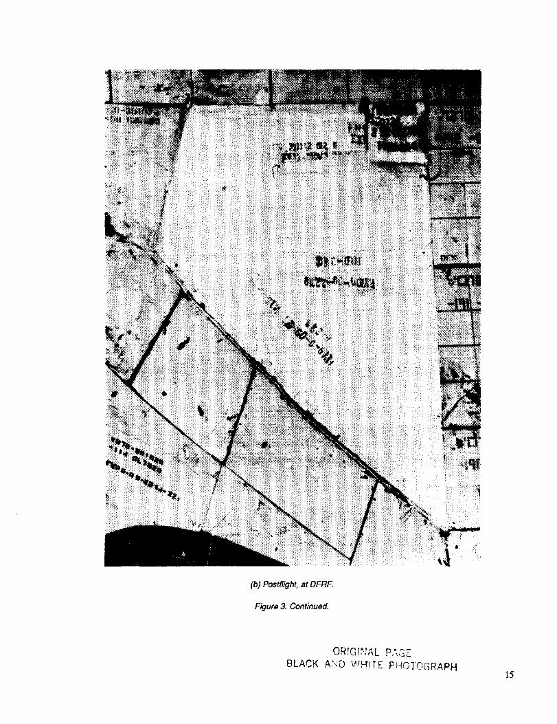
(b) Postflight, at DFRF.
Figure 3. Continued.
BLACK
P,",,S E
PHOf@GRAPH15
//
(c) Postflight, after ferry flight to KSC.
Figure 3. Concluded.
]6
ORIGINAL PAGE
BLACK AND WHITE PHOTOGRAPH
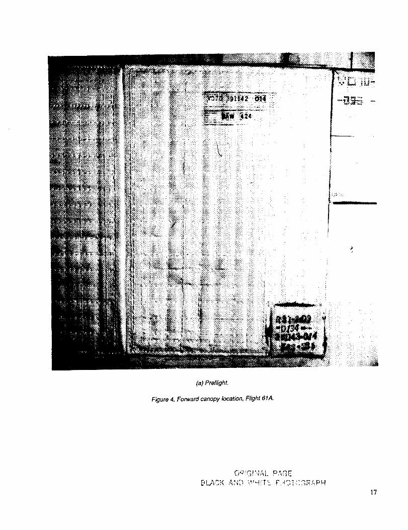
(a) Preflight.
Figure 4. Forward canopy location, Flight 61A.
t."- E_. i.r, I • t t ! D. ,_ _"
17

(b) Postflight, at DFRF.
Figure 4. Continued.
OR1G!NAL PAGE
8LACK AND WHITE PHO]OGRAPN
18

--++
(c) Postflight, after ferry flight to KSC.
Figure 4. Concluded.
_L " . ;.+, ,L +- !+_,.? '"i-{: _+- I" ;+-+"+_+," :.J ,<.._t+',4]9

,,n,
L
(a) Postflight, at DFRF.
Figure 5. Forward mid-fuselage location, Flight 61A.
2O
ORIGINAL PAGE
BLACK AND WHITE PHOTOGRAPH
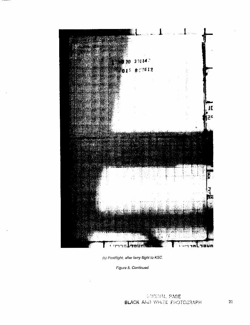
(b) Postflight, after ferry flight to KSC.
Figure 5. Continued.
......!'-!_',L
I_I.,ACK Ai,_i;) k<J,dkii_E "' ': T "_' ^ 21
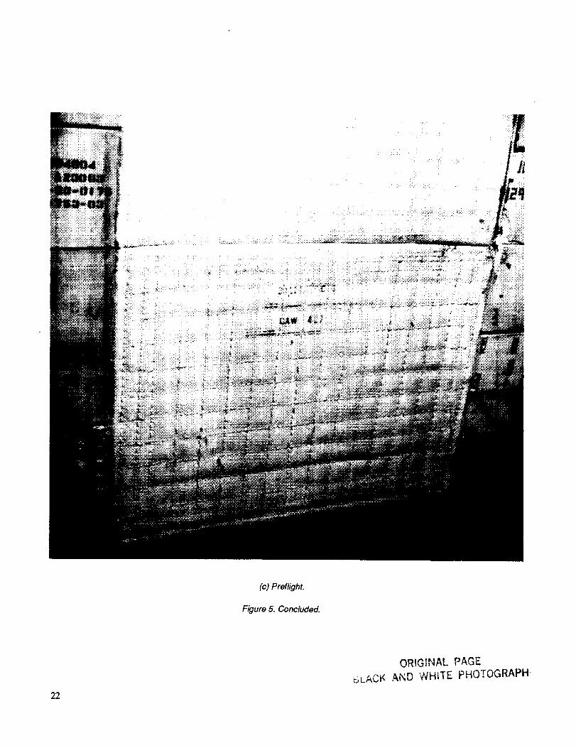
(c) Preflight.
Figure 5. Concluded.
22
ORIGINAL PAGE
5L.ACI< AND WHITE PHOTOGRAPH

(a) Preflight.
Figure 6. Mid-fuselage location, Flight 61A.
BLACK AND WH{TL FI4")_C:_.-_[:,'-PH23

(b) Postflight, at DFRFo
Figure 6. Continued.
24
ORIGINAL PAGE
BLACK AND WHITE PHOTOGRAPH

,,,_,W 37! '
(c) Postflight, after ferry flight to KSC.
Figure 6. Concluded.
• rlt r,' ,_.' _'HBLACK A;"_C W_-_'''-.,,:c " '-...... _.25
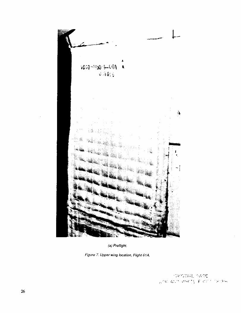
(a) Preflight.
Figure 7. Upper wing location, Flight 61A.
26
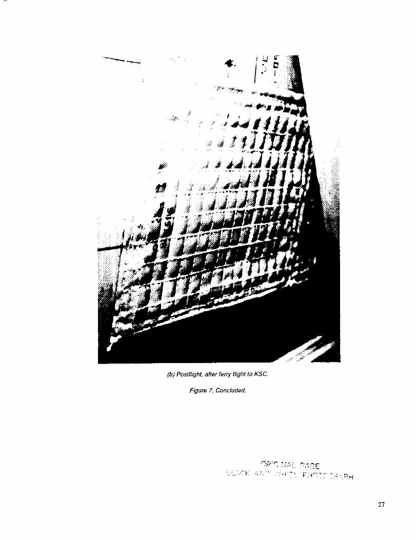
(b) Postflight, after ferry flight to KSC.
Figure 7. Concluded.
_ _'_, _ l'_ " _ _, i_ _. _'_ ;_ .._,
2"7
i
.)
(a) Postflight, at DFRF.
Figure 8. Vertical tail location, Flight 61A.
ORIGINAL PAG_
_3LACK AND WHITE PHOTCG_-_APN
28

(b) Postflight, after ferry flight to KSC.
Figure 8. Continued.
BLACK ANLq ,'/H'-" ",_r.. Piti._i L ._,_,.,p_4 29

I¢
mill
_:_" ..__._,_ .........
I
I
K
I_IYII
-flu
;_laR I
I
(c) Preflight.
Figure 8. Concluded.
3O
:j}_iGiI',IAL PAGE
e,L.ACK AND W'H_'TE Pt_'O-ioGRAPH
/
//
/
(a) Preflight.
Figure 9. Rudder�speed brake location, Flight 61A.
BLAC,'_ A_':;3 " LJ.-, ,,,"_ 31
i
(b) Postflight, at DFRF.
Figure 9. Continued.
32
ORIGINAL PAGE
b;..AC_. AI'4O _,*,/HITE. pI4OTOGRAPH
t •
%.
f
/
//
" ,. fll I ,,
"'j
/
//
/
o_
(c) Postffight, after ferry flight to KSC.
Figure 9. Concluded.
BLACK Ab;i3 W_.: :E F I-_C,i CC--RAPH33
Form ApprovedREPORT DOCUMENTATION PAGE oM8Noo7o4-o188
Public reporting burden for this collection of information is es ma ed to average I hour per response including the lime for reviewm instrucl_ons sear h_
i gat.het!ng and malntalntn_l'' the data needed, and completing and reviewing the collect on o nformalion. Send _,,,,,,o.,=............,eyarumg tn=s_LuuroenL_ estlma' eCornganyeXistingotheraspectdatasourceS,ofIhiscollection O! information Includ ng sggoest one loT reducing this burden to Washington Headquarters Services Directorate for mlormahon era i nDavis H hwa Suite 1204 Arlin t n - ' , Op o s and Reports. 1215 Jet erson
Ig y, , g o , _/A 22202 4302. anglo the Office of Management and Budget, Paperwork Reduchon Project (0704-0188). Washington. DC 205,03.
1. AGENCY USE ONLY (Leave blank) 2. REPORT DATE 3. REPORT TYPE AND DATES COVERED
April 1992 Technical Memorandum4. TITLE AND SUBTITLE
Performance of Uncoated AFRSI Blankets during Multiple SpaceShuttle Flights
6. AUTHOR(S)
7,
Paul M. Sawko and Howard E. Goldstein
PERFORMINGORGANIZATIONNAME(S)ANDADDRESS(ES)
Ames Research Center
Moffett Field, CA 94035-1000
SPONSORING/MONITORINGAGENCYNAME(S)ANDADDRESS(ES)
National Aeronautics and Space AdministrationWashington, DC 20546-0001
11. SUPPLEMENTARY NOTES
5. FUNDING NUMBERS
506-43-31
8. PERFORMING ORGANIZATIONREPORT NUMBER
A-91237
10. SPONSORING/MONITORINGAGENCY REPORT NUMBER
NASA TM- 103892
Point of Contact: Paul M. Sawko, Ames Research Center, MS 234-1, Moffett Field, CA 94035-1000(415) 604-6079 or FTS 464-6079
12a. DISTRIBUTION/AVAILABILITY STATEMENT
Unclassified-Unlimited
Subject Category - 15
13. ABSTRACT (Maximum 200 words)
12b. DISTRIBUTION CODE
UncoatedAdvanced Flexible Reusable Surface Insulation (AFRSI) blankets were successfully flown on
seven consecutive flights of the Space Shuttle Orbiter OV-099 (Challenger). In six of the eight locationsmonitored (forward windshield, forward canopy, mid-fuselage, upper wing, rudder/speed brake, and verticaltail), the AFRSI blankets performed well during the ascent and reentry exposure to the thermal and
aeroacoustic environments. Several of the uncoated AFRSI blankets that sustained minor damage, such asfraying or broken threads, could be repaired by sewing or by patching with a surface coating called C-9. Thechief reasons for replacing or completely coating a blanket were fabric en_brittlement and fabric abrasion
caused by wind erosion. This occurred in the orbiter maneuvering system (OMS) pod sidewall and theforward mid-fuselage locations.
14. SUBJECTTERMS
AFRSI blankets, Flexible ceramic blankets, Thermal protection system,Blanket performance, Space Shuttle
17. SECURITYCLASSIFICATION18. SECURITYCLASSIFICATION19. SECURITYCLASSIFICATIONOFREPORT OFTHISPAGE OFABSTRACTUnclassified Unclassified
NSN7540-01-2B0-5500
[15. NUMBER OF PAGES
3616. PRICE CODE
A0320. LIMITATION OF ABSTRACT
Standard Form 298 (Rev. 2-89)Prescribed by ANSI Std. Z39-1e298-102