Embed Size (px)
Citation preview
September 2017 DocID030981 Rev 1 1/35
www.st.com
UM2284 User manual
Getting started with the ST-PLC App for ladder logic programming
Introduction The ST-PLC App allows drawing a ladder logic program for the X-NUCLEO-PLC01A1 expansion board, compile it and send the list of instructions to the PLC via Wi-Fi.
The ladder logic is the main programming language for industrial programmable logic controllers (PLC). It is a visual and graphical language which can generate low level code to drive ON/OFF utilities connected to the PLC outputs.
The ladder logic implemented in the ST-PLC App is based on primitive logic operators (AND, OR, NOT) and is regulated by the IEC 61131-3 standard.
The application is available for Windows 7, Android and iOS operating systems.
The application features:
Project design
New project
Modify project
Duplicate project
Ladder design
PLC programming
Ladder deploy
Diagnostics
Device status
Connection settings
The ST-PLC App for mobiles uses Wi-Fi and tablet or smartphone storage space.
The application desktop version includes a self-hosted service that integrates the connection feature to the board via the TCP/IP protocol.
Contents UM2284
2/35 DocID030981 Rev 1
Contents
1 Getting started ................................................................................. 5
1.1 ST-PLC App startup .......................................................................... 5
1.2 ST-PLC App home page ................................................................... 7
1.3 ST-PLC App project features ............................................................ 8
1.3.1 Create a new project .......................................................................... 8
1.3.2 Duplicate a project .............................................................................. 9
1.3.3 Project detail page ............................................................................ 10
1.3.4 Modify a project ................................................................................ 11
1.3.5 Save a project ................................................................................... 12
1.3.6 Delete a project ................................................................................ 13
1.3.7 Project preview ................................................................................. 14
1.3.8 Modify a rung .................................................................................... 15
1.3.9 Delete a rung .................................................................................... 16
1.3.10 Deploy a rung ................................................................................... 17
1.3.11 How to design a rung........................................................................ 18
2 Ladder element .............................................................................. 21
2.1 Input/output elements ...................................................................... 21
2.2 Timer/counter elements .................................................................. 22
2.3 Validation rules ................................................................................ 23
3 Ladder deployment ....................................................................... 27
4 Diagnostics .................................................................................... 29
4.1 Connection settings ......................................................................... 29
4.2 ICs status ........................................................................................ 30
5 ST-PLC App desktop version ....................................................... 32
Appendix A Known issues/troubleshooting ................................ 33
6 Revision history ............................................................................ 34
UM2284 List of tables
DocID030981 Rev 1 3/35
List of tables
Table 1: Required parameters for the input/output diagram element ....................................................... 21 Table 2: Required parameters for the timer/counter diagram element ..................................................... 22 Table 3: Document revision history .......................................................................................................... 34
List of figures UM2284
4/35 DocID030981 Rev 1
List of figures
Figure 1: ST-PLC App startup slide ............................................................................................................ 5 Figure 2: ST-PLC App: expansion boards information window .................................................................. 6 Figure 3: ST-PLC App New Project window ............................................................................................... 7 Figure 4: ST-PLC App Connection settings window ................................................................................... 7 Figure 5: ST-PLC App new project creation ............................................................................................... 8 Figure 6: ST-PLC App new project creation ............................................................................................... 9 Figure 7: ST-PLC App project detail page ................................................................................................ 10 Figure 8: ST-PLC App: modify the project ................................................................................................ 11 Figure 9: ST-PLC App: modify the project ................................................................................................ 12 Figure 10: ST-PLC App: delete the project ............................................................................................... 13 Figure 11: ST-PLC App: project rung set preview .................................................................................... 14 Figure 12: ST-PLC App: modifying a rung ................................................................................................ 15 Figure 13: ST-PLC App: delete a rung ..................................................................................................... 16 Figure 14: ST-PLC App: deploy a rung to PLC ........................................................................................ 17 Figure 15: ST-PLC App: edit rung ............................................................................................................ 18 Figure 16: ST-PLC App: block info window .............................................................................................. 19 Figure 17: ST-PLC App: block info window .............................................................................................. 19 Figure 18: Timer/counter diagram element virtual input example ............................................................ 22 Figure 19: ST-PLC App validation rule 1: connection error ...................................................................... 23 Figure 20: ST-PLC App validation rule 2: single output connection error ................................................ 24 Figure 21: ST-PLC App validation rule 3: output symbol error ................................................................. 24 Figure 22: ST-PLC App validation rule 4: saving a rung without output error .......................................... 25 Figure 23: ST-PLC App validation rule 5: short-circuit error ..................................................................... 25 Figure 24: ST-PLC App validation rule 6: OR block error ......................................................................... 26 Figure 25: ST-PLC App: commands for PLC programming ..................................................................... 27 Figure 26: ST-PLC App: PLC programming connection error .................................................................. 28 Figure 27: ST-PLC App: PLC programming successful connection ......................................................... 28 Figure 28: ST-PLC App: Wi-Fi connection................................................................................................ 29 Figure 29: ST-PLC App: ICs status .......................................................................................................... 30 Figure 30: ST-PLC App desktop version .................................................................................................. 32 Figure 31: ST-PLC App desktop version: X-Nucleo PLC service ............................................................. 32
UM2284 Getting started
DocID030981 Rev 1 5/35
1 Getting started
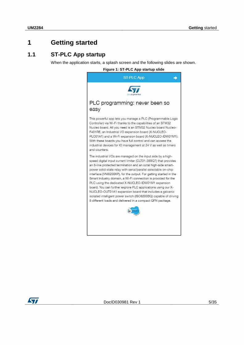
1.1 ST-PLC App startup
When the application starts, a splash screen and the following slides are shown.
Figure 1: ST-PLC App startup slide
Getting started UM2284
6/35 DocID030981 Rev 1
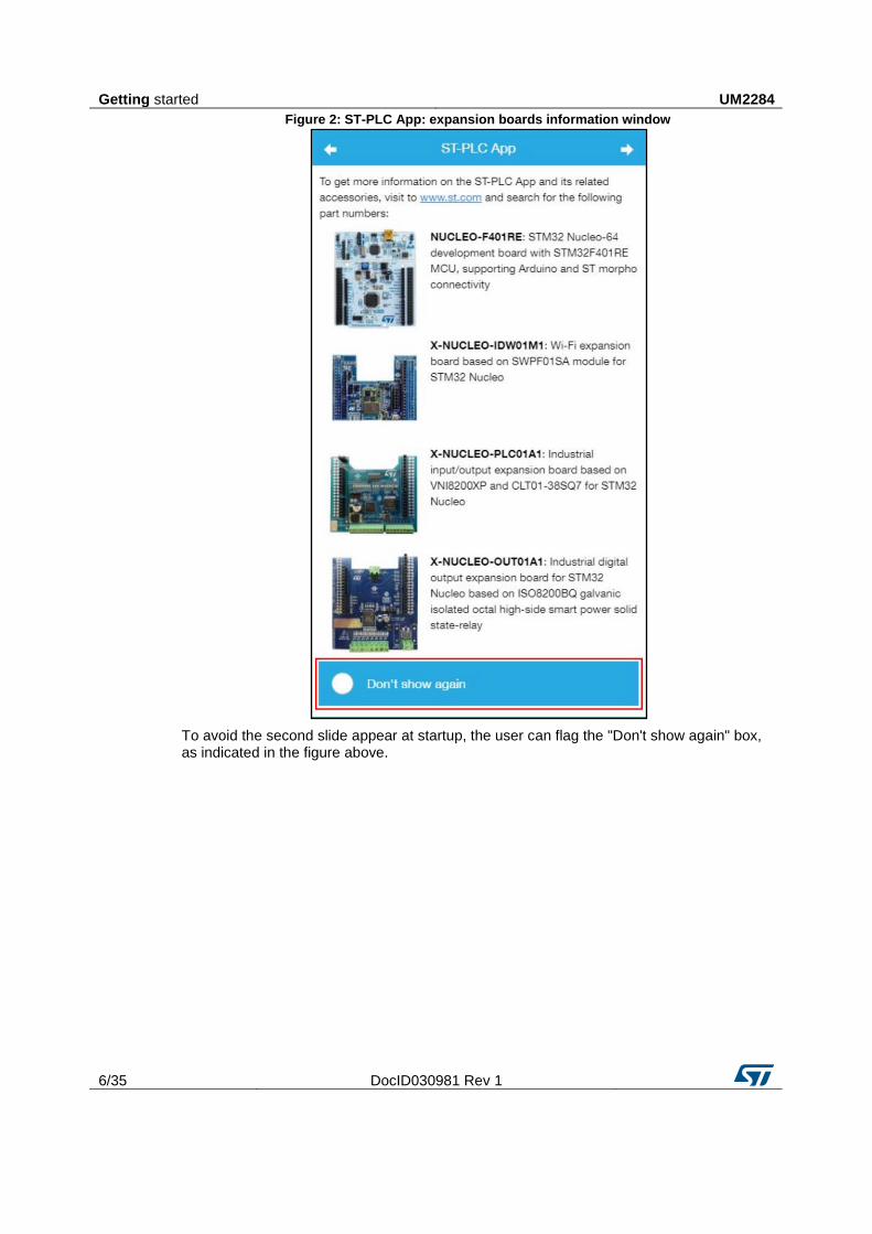
Figure 2: ST-PLC App: expansion boards information window
To avoid the second slide appear at startup, the user can flag the "Don't show again" box, as indicated in the figure above.
UM2284 Getting started
DocID030981 Rev 1 7/35
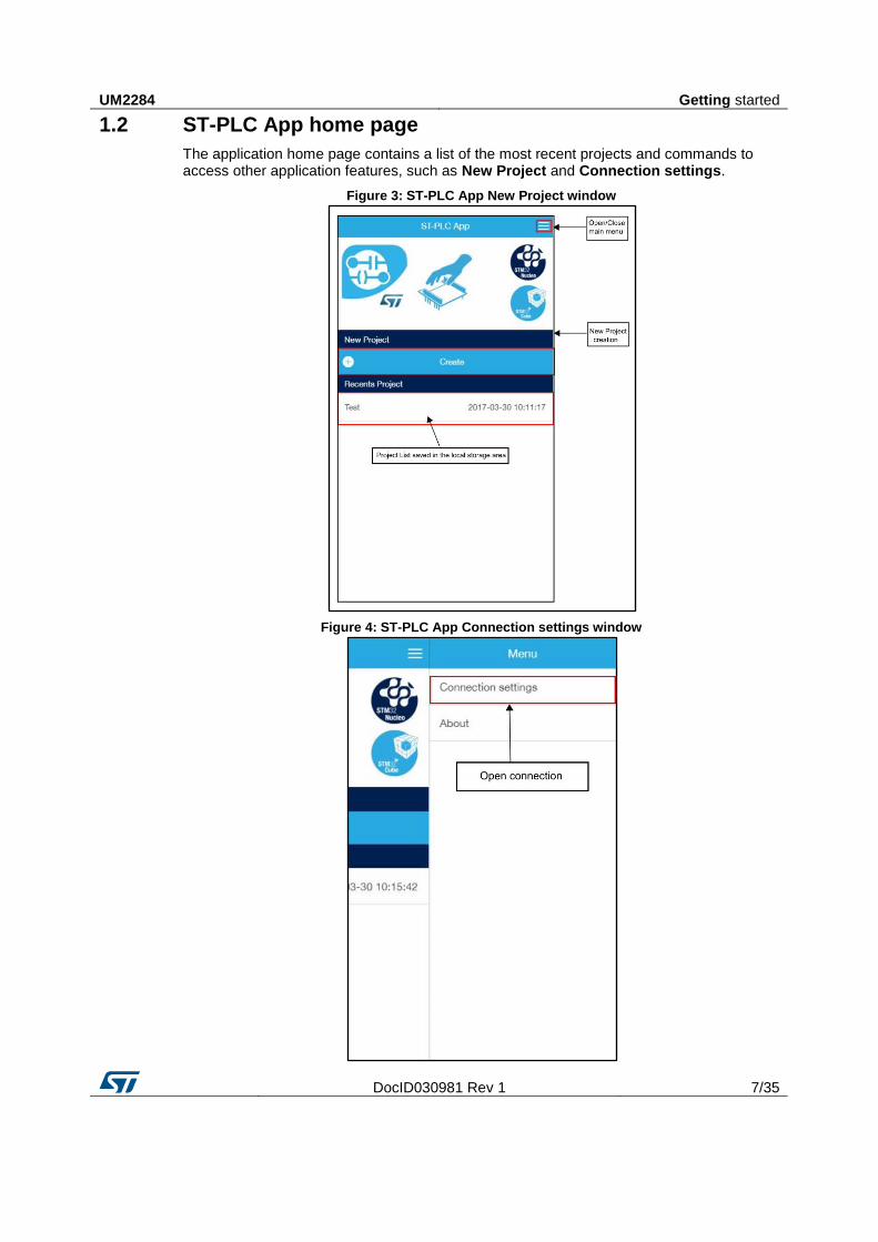
1.2 ST-PLC App home page
The application home page contains a list of the most recent projects and commands to access other application features, such as New Project and Connection settings.
Figure 3: ST-PLC App New Project window
Figure 4: ST-PLC App Connection settings window
Getting started UM2284
8/35 DocID030981 Rev 1
1.3 ST-PLC App project features
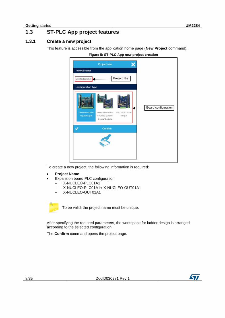
1.3.1 Create a new project
This feature is accessible from the application home page (New Project command).
Figure 5: ST-PLC App new project creation
To create a new project, the following information is required:
Project Name
Expansion board PLC configuration:
X-NUCLEO-PLC01A1
X-NUCLEO-PLC01A1+ X-NUCLEO-OUT01A1
X-NUCLEO-OUT01A1
To be valid, the project name must be unique.
After specifying the required parameters, the workspace for ladder design is arranged according to the selected configuration.
The Confirm command opens the project page.
UM2284 Getting started
DocID030981 Rev 1 9/35
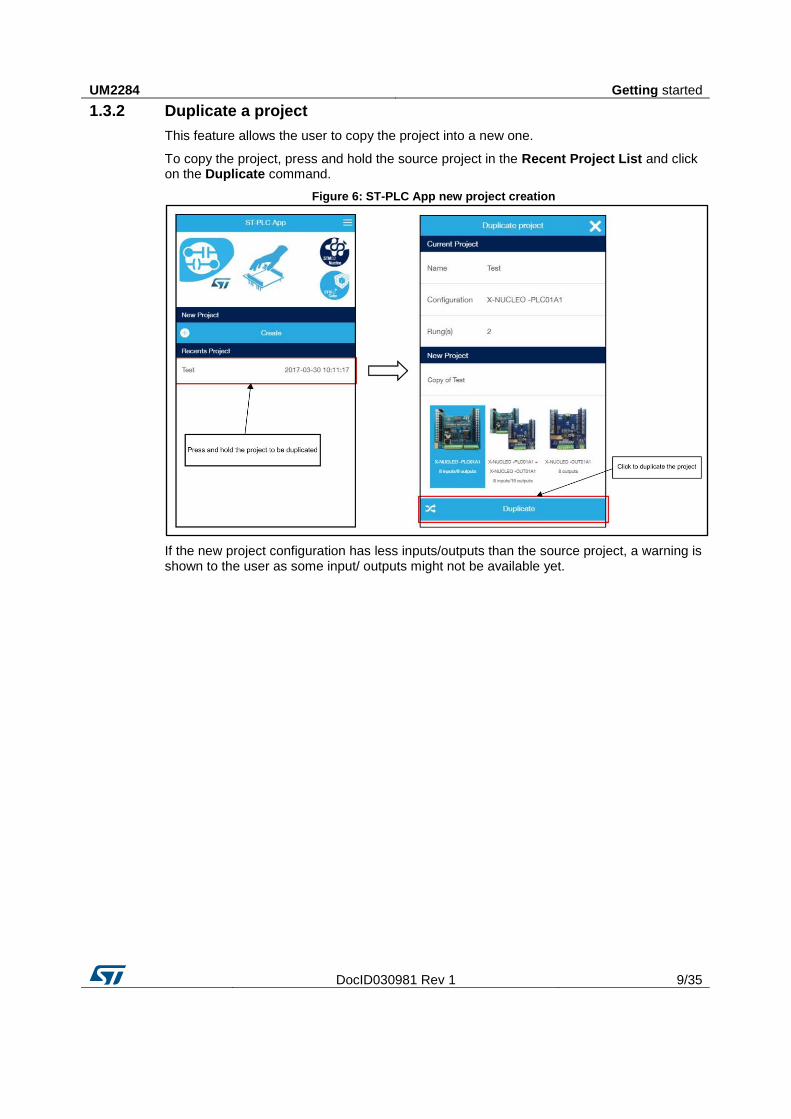
1.3.2 Duplicate a project
This feature allows the user to copy the project into a new one.
To copy the project, press and hold the source project in the Recent Project List and click on the Duplicate command.
Figure 6: ST-PLC App new project creation
If the new project configuration has less inputs/outputs than the source project, a warning is shown to the user as some input/ outputs might not be available yet.
Getting started UM2284
10/35 DocID030981 Rev 1
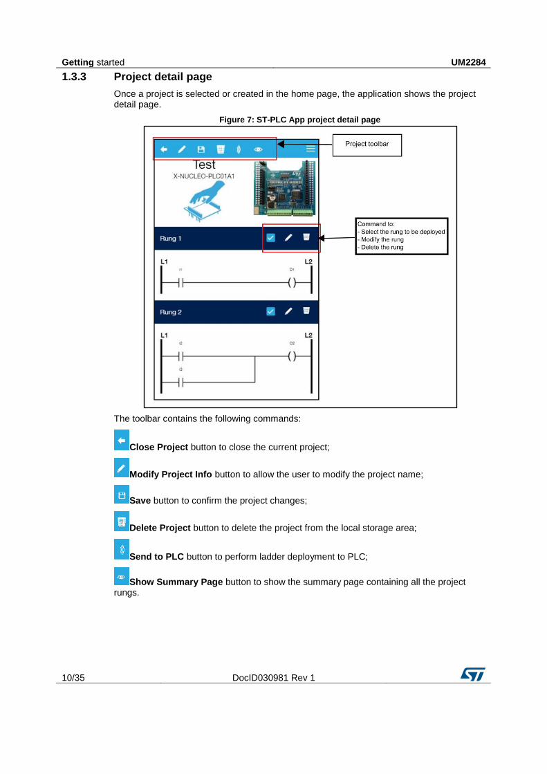
1.3.3 Project detail page
Once a project is selected or created in the home page, the application shows the project detail page.
Figure 7: ST-PLC App project detail page
The toolbar contains the following commands:
Close Project button to close the current project;
Modify Project Info button to allow the user to modify the project name;
Save button to confirm the project changes;
Delete Project button to delete the project from the local storage area;
Send to PLC button to perform ladder deployment to PLC;
Show Summary Page button to show the summary page containing all the project rungs.
UM2284 Getting started
DocID030981 Rev 1 11/35
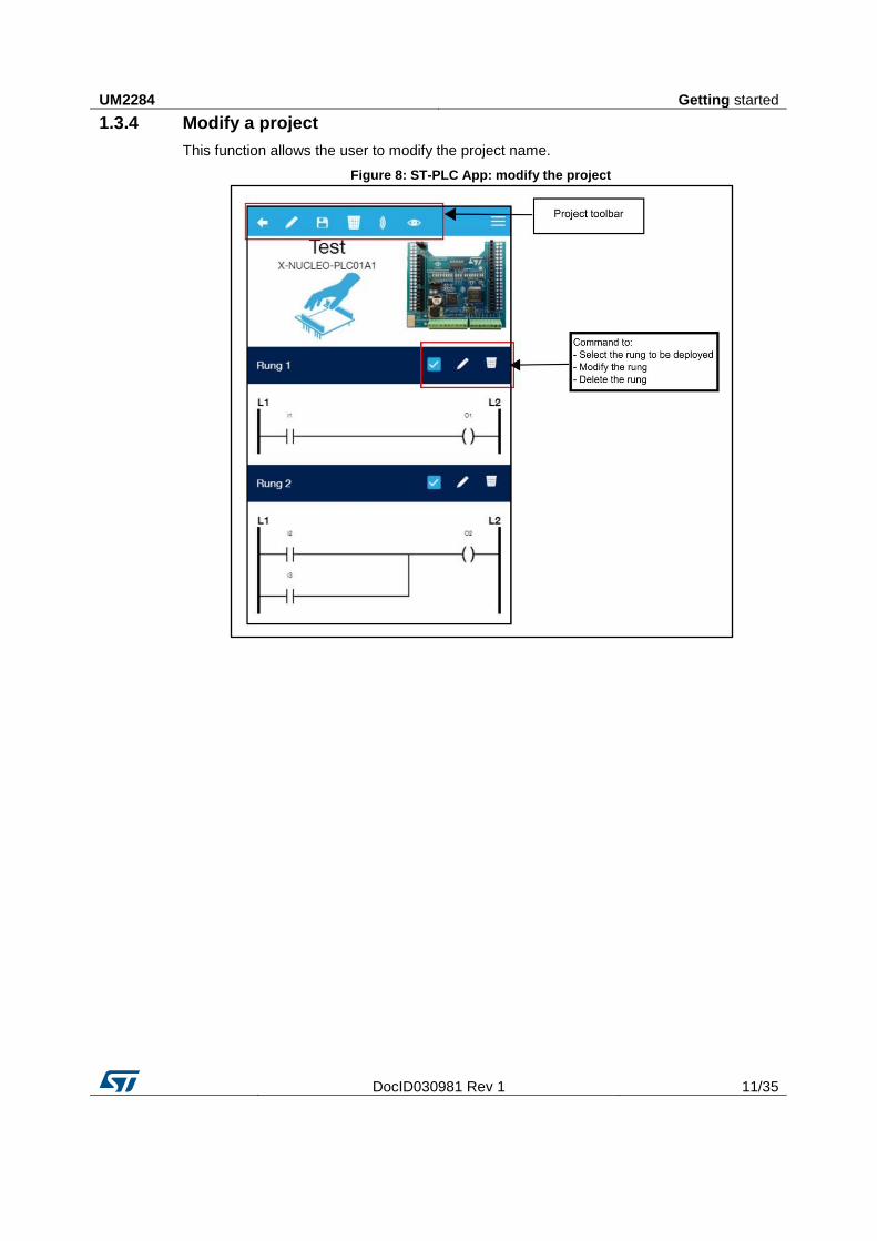
1.3.4 Modify a project
This function allows the user to modify the project name.
Figure 8: ST-PLC App: modify the project
Getting started UM2284
12/35 DocID030981 Rev 1
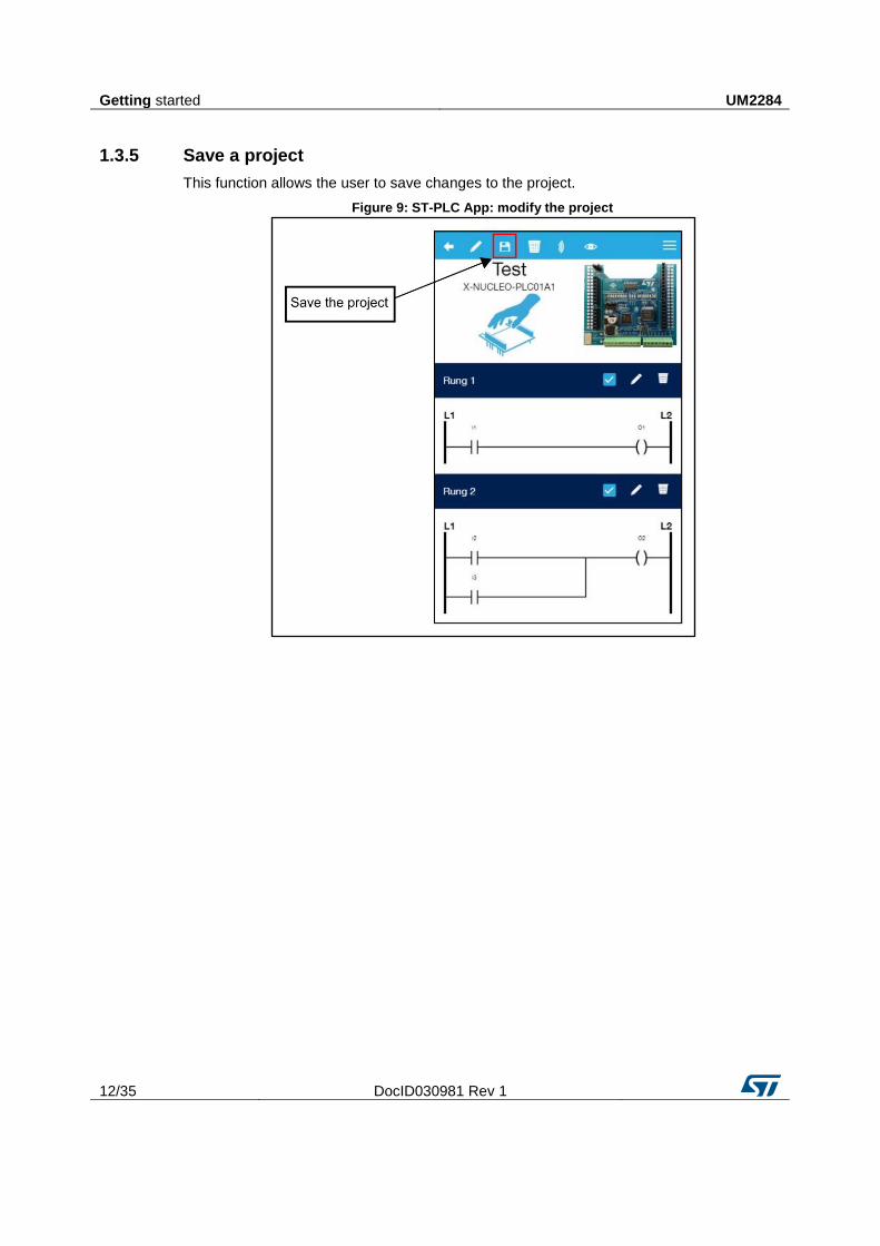
1.3.5 Save a project
This function allows the user to save changes to the project.
Figure 9: ST-PLC App: modify the project
UM2284 Getting started
DocID030981 Rev 1 13/35
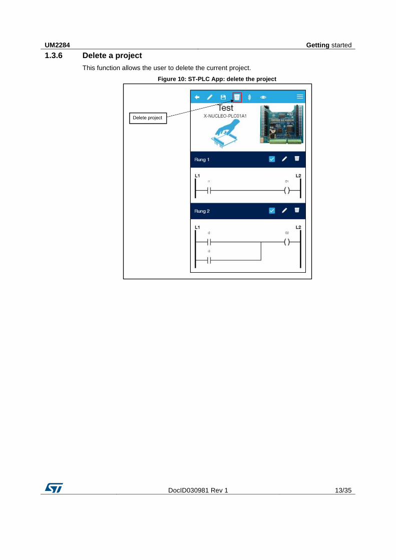
1.3.6 Delete a project
This function allows the user to delete the current project.
Figure 10: ST-PLC App: delete the project
Getting started UM2284
14/35 DocID030981 Rev 1
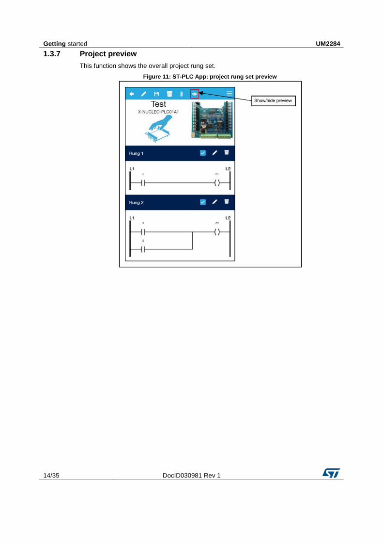
1.3.7 Project preview
This function shows the overall project rung set.
Figure 11: ST-PLC App: project rung set preview
UM2284 Getting started
DocID030981 Rev 1 15/35
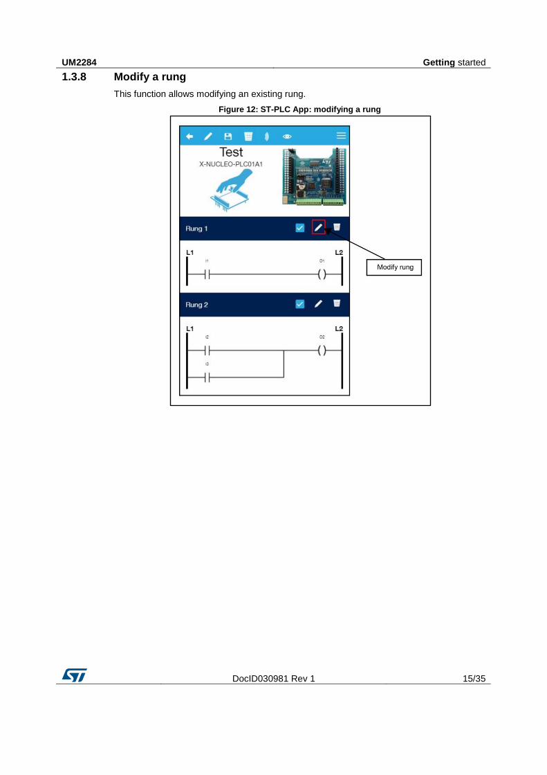
1.3.8 Modify a rung
This function allows modifying an existing rung.
Figure 12: ST-PLC App: modifying a rung
Getting started UM2284
16/35 DocID030981 Rev 1
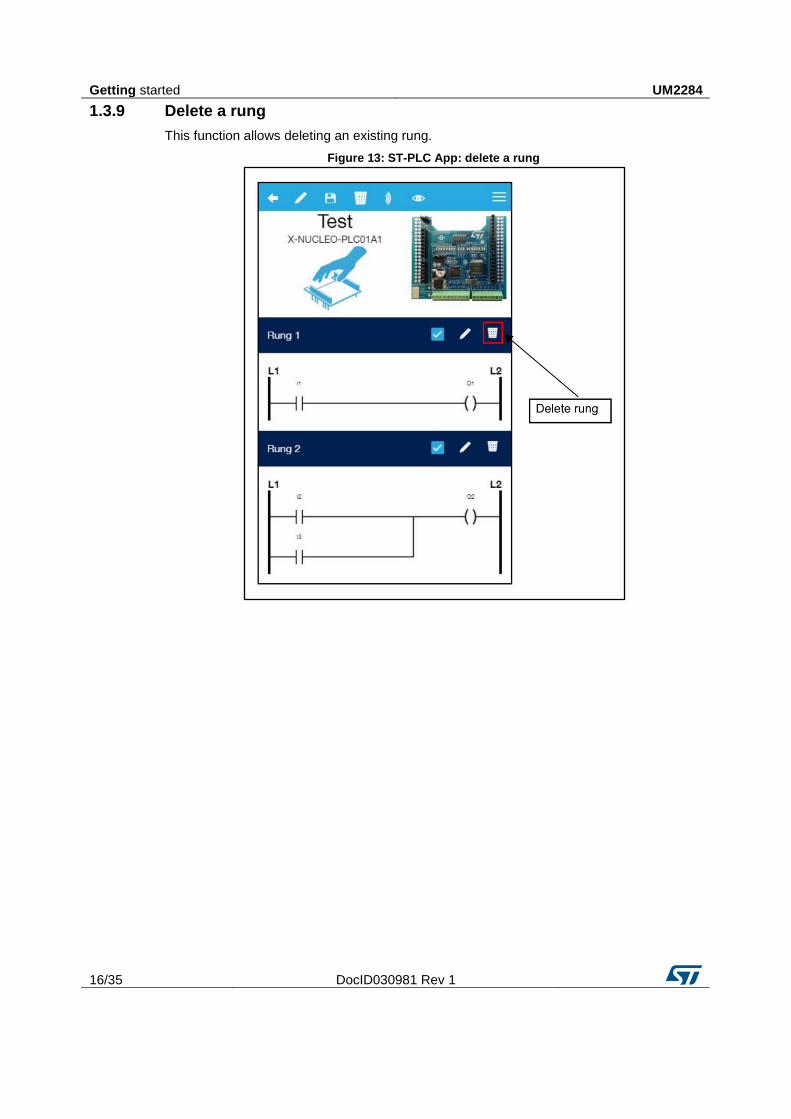
1.3.9 Delete a rung
This function allows deleting an existing rung.
Figure 13: ST-PLC App: delete a rung
UM2284 Getting started
DocID030981 Rev 1 17/35
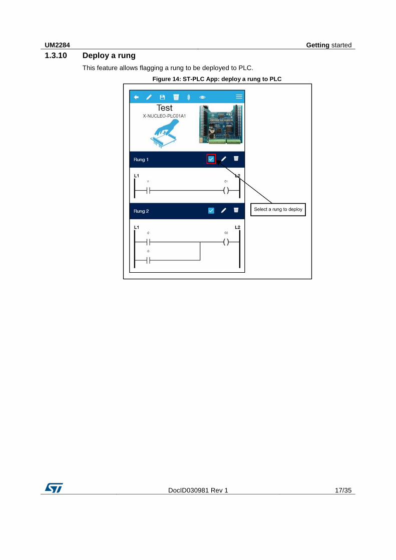
1.3.10 Deploy a rung
This feature allows flagging a rung to be deployed to PLC.
Figure 14: ST-PLC App: deploy a rung to PLC
Getting started UM2284
18/35 DocID030981 Rev 1
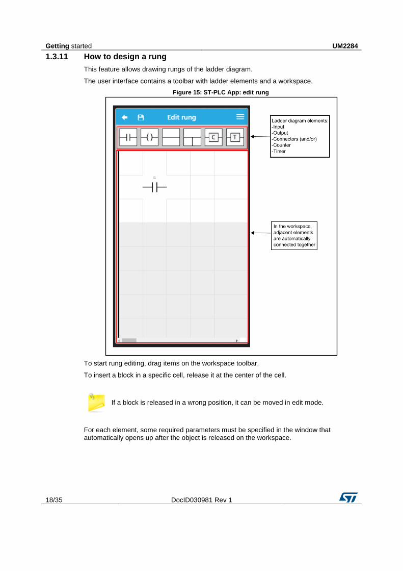
1.3.11 How to design a rung
This feature allows drawing rungs of the ladder diagram.
The user interface contains a toolbar with ladder elements and a workspace.
Figure 15: ST-PLC App: edit rung
To start rung editing, drag items on the workspace toolbar.
To insert a block in a specific cell, release it at the center of the cell.
If a block is released in a wrong position, it can be moved in edit mode.
For each element, some required parameters must be specified in the window that automatically opens up after the object is released on the workspace.
UM2284 Getting started
DocID030981 Rev 1 19/35
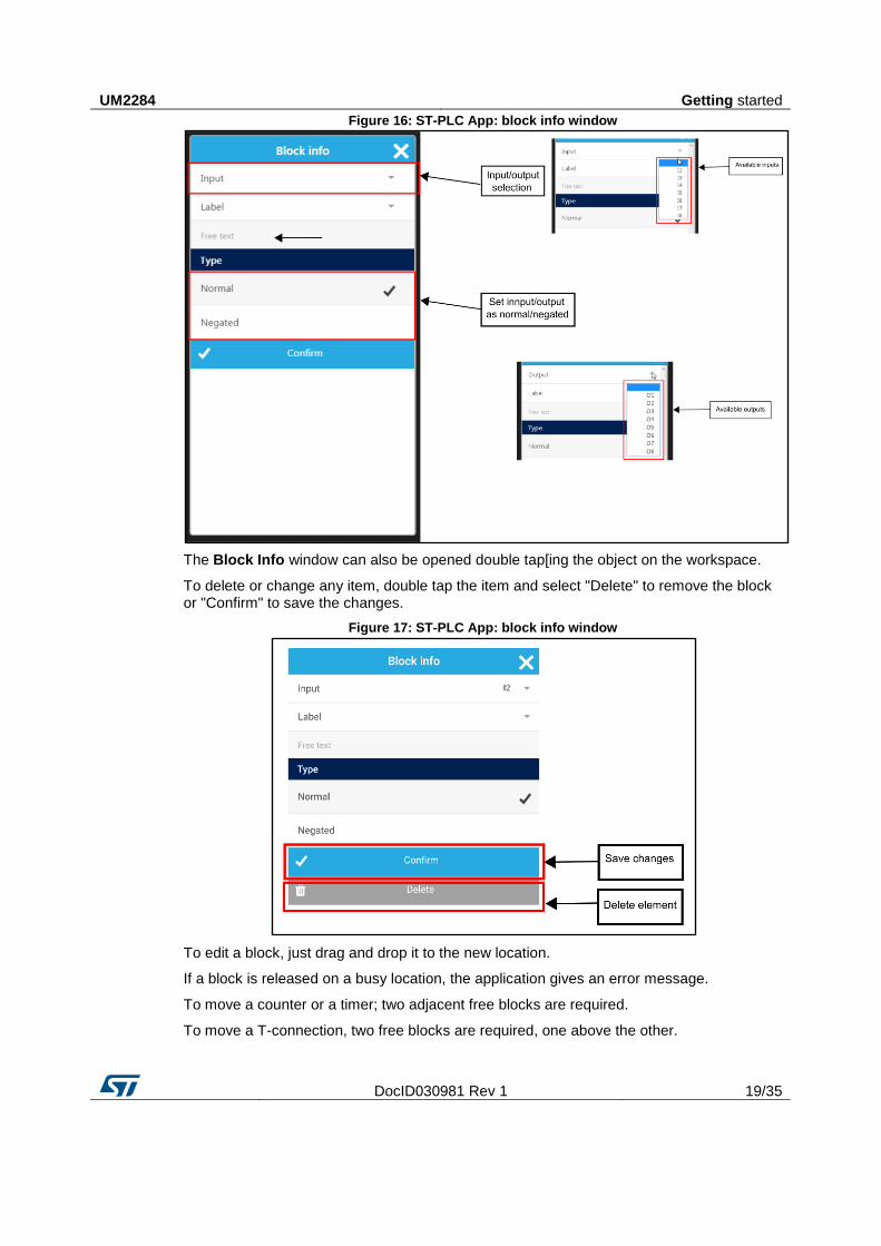
Figure 16: ST-PLC App: block info window
The Block Info window can also be opened double tap[ing the object on the workspace.
To delete or change any item, double tap the item and select "Delete" to remove the block or "Confirm" to save the changes.
Figure 17: ST-PLC App: block info window
To edit a block, just drag and drop it to the new location.
If a block is released on a busy location, the application gives an error message.
To move a counter or a timer; two adjacent free blocks are required.
To move a T-connection, two free blocks are required, one above the other.
Getting started UM2284
20/35 DocID030981 Rev 1
The T-connection is automatically updated when a component is released on the left or on the right, to facilitate the branch creation the during the design phase.
This automatic update, in case of an user error in positioning a component adjacent to the T-connection, might cause an invalid link; in this case, you will be required to rebuild the affected part.
UM2284 Ladder element
DocID030981 Rev 1 21/35
2 Ladder element
2.1 Input/output elements
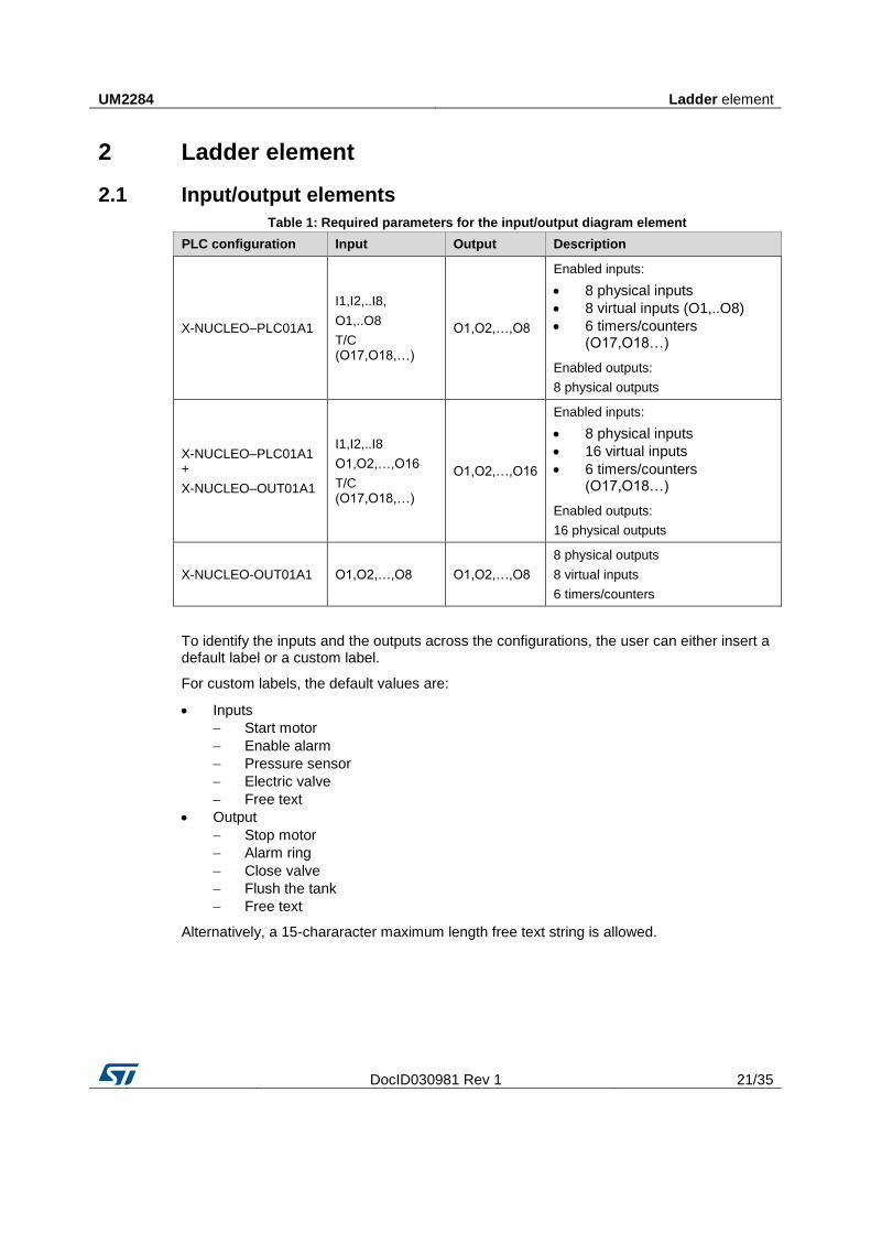
Table 1: Required parameters for the input/output diagram element
PLC configuration Input Output Description
X-NUCLEO–PLC01A1
I1,I2,..I8,
O1,..O8
T/C (O17,O18,…)
O1,O2,…,O8
Enabled inputs:
8 physical inputs
8 virtual inputs (O1,..O8)
6 timers/counters (O17,O18…)
Enabled outputs:
8 physical outputs
X-NUCLEO–PLC01A1 +
X-NUCLEO–OUT01A1
I1,I2,..I8
O1,O2,…,O16
T/C (O17,O18,…)
O1,O2,…,O16
Enabled inputs:
8 physical inputs
16 virtual inputs
6 timers/counters (O17,O18…)
Enabled outputs:
16 physical outputs
X-NUCLEO-OUT01A1 O1,O2,…,O8 O1,O2,…,O8
8 physical outputs
8 virtual inputs
6 timers/counters
To identify the inputs and the outputs across the configurations, the user can either insert a default label or a custom label.
For custom labels, the default values are:
Inputs
Start motor
Enable alarm
Pressure sensor
Electric valve
Free text
Output
Stop motor
Alarm ring
Close valve
Flush the tank
Free text
Alternatively, a 15-chararacter maximum length free text string is allowed.
Ladder element UM2284
22/35 DocID030981 Rev 1
2.2 Timer/counter elements
Table 2: Required parameters for the timer/counter diagram element
Element Parameter
Timer
N: a number identifying the counter, from 0 to 4095
T: time base
P: preset value
EN/DIS: a flag indicating the timer initial status (ON / OFF) if there is no specified input;
otherwise, this parameter can be omitted
Output: internal contact identified with a numbering higher than O16
Counter
N: counter number
SV: set value
U/D: up counter = 1, down counter = 0
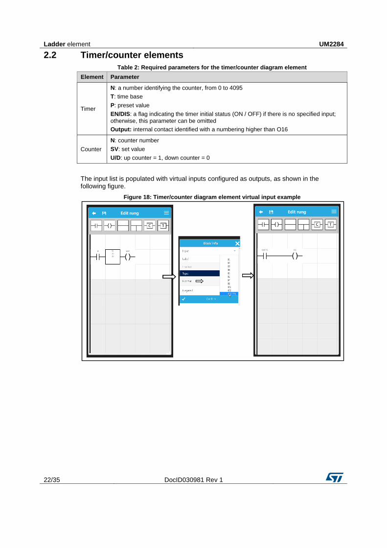
The input list is populated with virtual inputs configured as outputs, as shown in the following figure.
Figure 18: Timer/counter diagram element virtual input example
UM2284 Ladder element
DocID030981 Rev 1 23/35
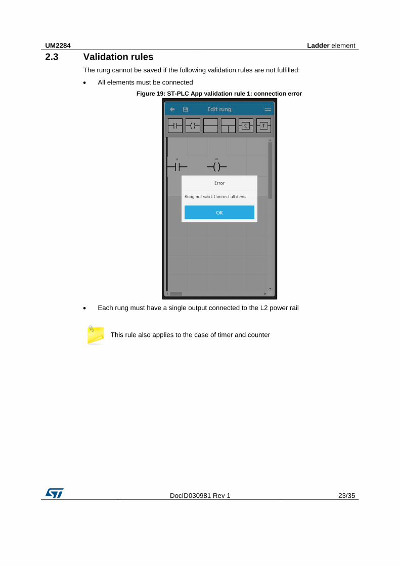
2.3 Validation rules
The rung cannot be saved if the following validation rules are not fulfilled:
All elements must be connected
Figure 19: ST-PLC App validation rule 1: connection error
Each rung must have a single output connected to the L2 power rail
This rule also applies to the case of timer and counter
Ladder element UM2284
24/35 DocID030981 Rev 1
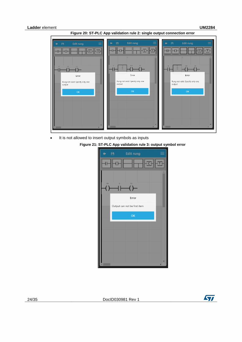
Figure 20: ST-PLC App validation rule 2: single output connection error
It is not allowed to insert output symbols as inputs
Figure 21: ST-PLC App validation rule 3: output symbol error
UM2284 Ladder element
DocID030981 Rev 1 25/35
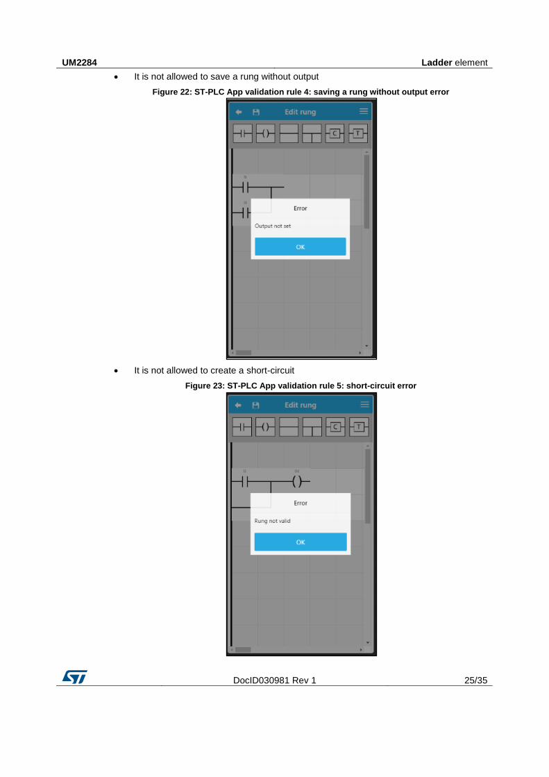
It is not allowed to save a rung without output
Figure 22: ST-PLC App validation rule 4: saving a rung without output error
It is not allowed to create a short-circuit
Figure 23: ST-PLC App validation rule 5: short-circuit error
Ladder element UM2284
26/35 DocID030981 Rev 1
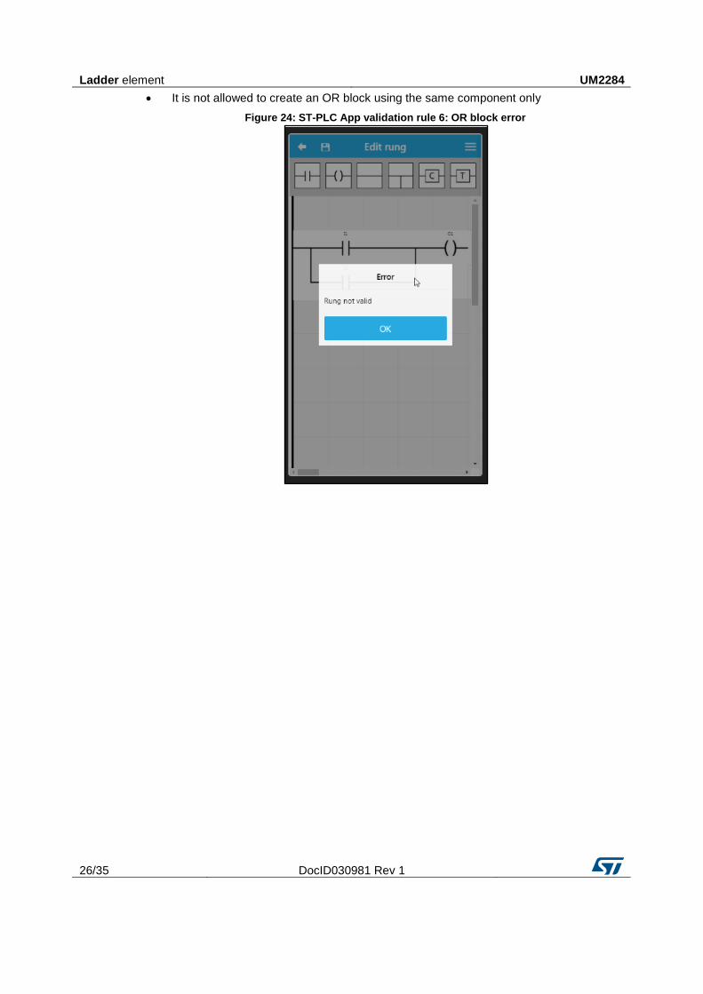
It is not allowed to create an OR block using the same component only
Figure 24: ST-PLC App validation rule 6: OR block error
UM2284 Ladder deployment
DocID030981 Rev 1 27/35
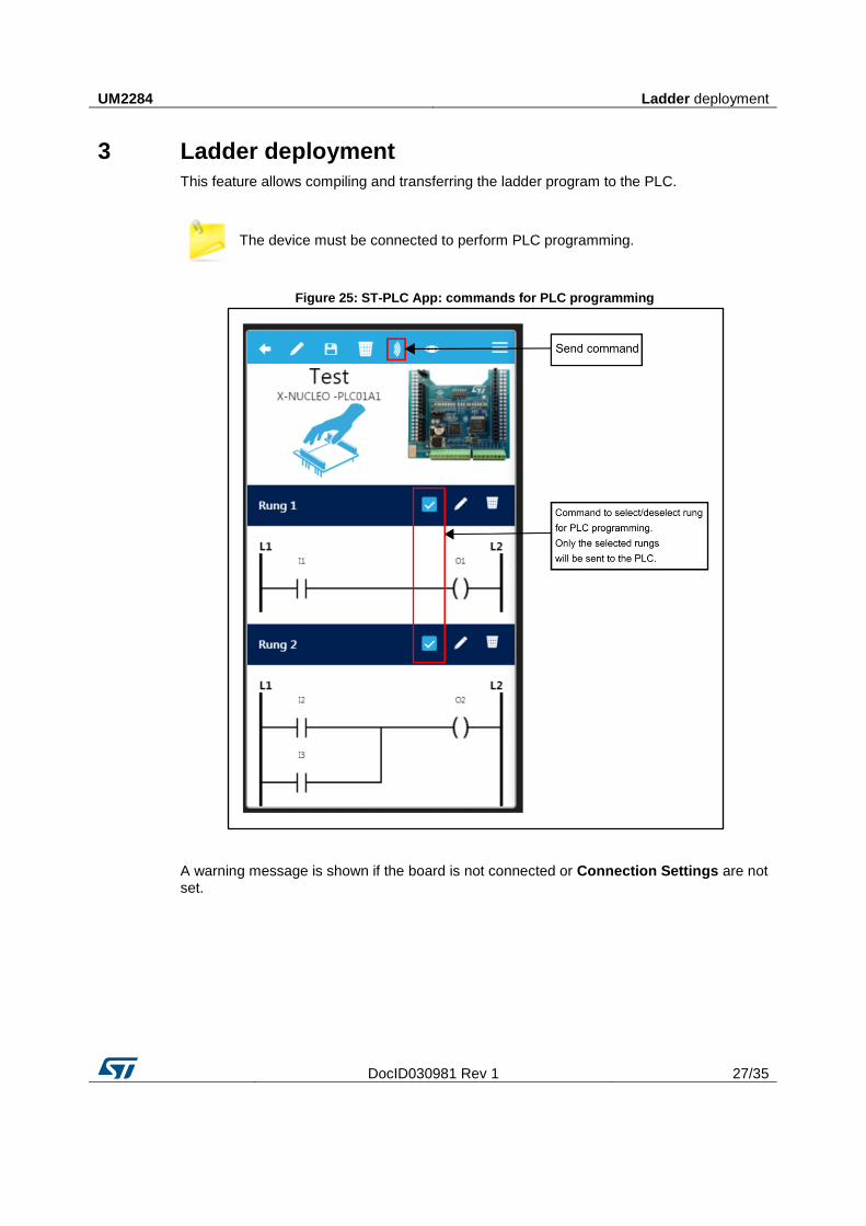
3 Ladder deployment
This feature allows compiling and transferring the ladder program to the PLC.
The device must be connected to perform PLC programming.
Figure 25: ST-PLC App: commands for PLC programming
A warning message is shown if the board is not connected or Connection Settings are not set.
Ladder deployment UM2284
28/35 DocID030981 Rev 1
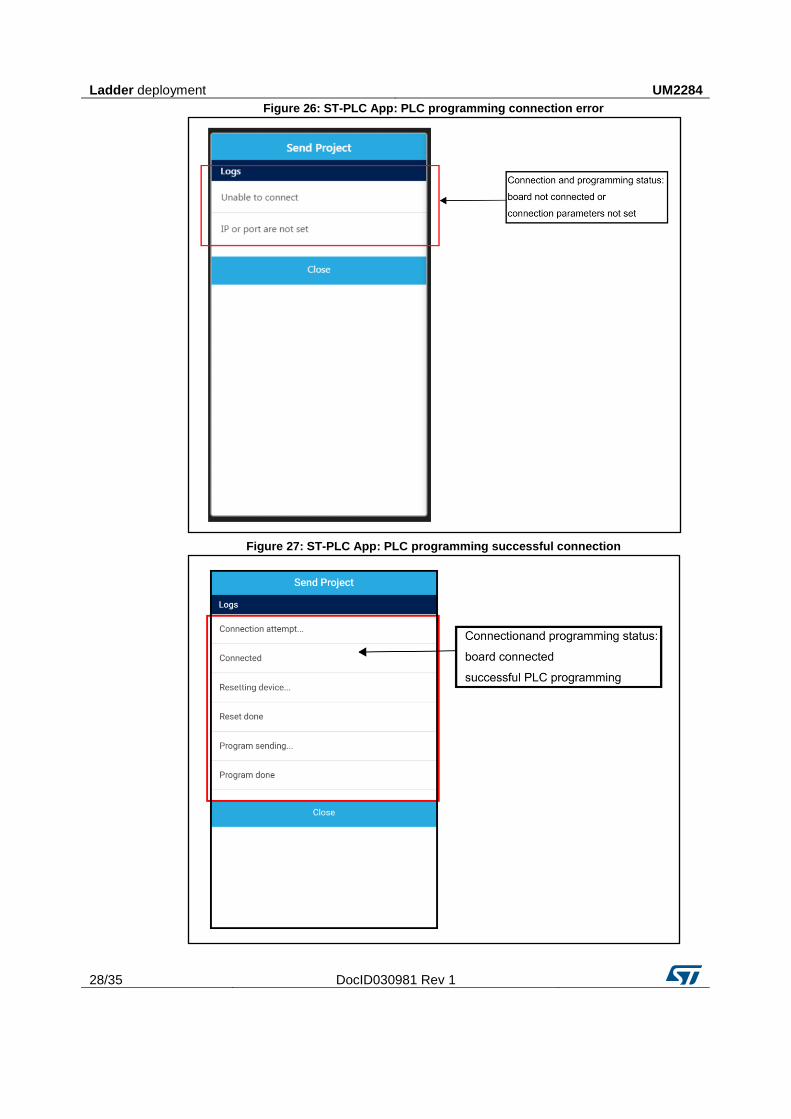
Figure 26: ST-PLC App: PLC programming connection error
Figure 27: ST-PLC App: PLC programming successful connection
UM2284 Diagnostics
DocID030981 Rev 1 29/35
4 Diagnostics
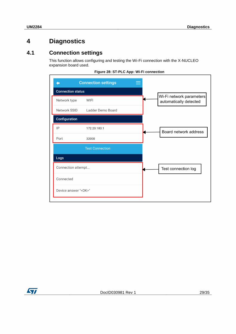
4.1 Connection settings
This function allows configuring and testing the Wi-Fi connection with the X-NUCLEO expansion board used.
Figure 28: ST-PLC App: Wi-Fi connection
Diagnostics UM2284
30/35 DocID030981 Rev 1
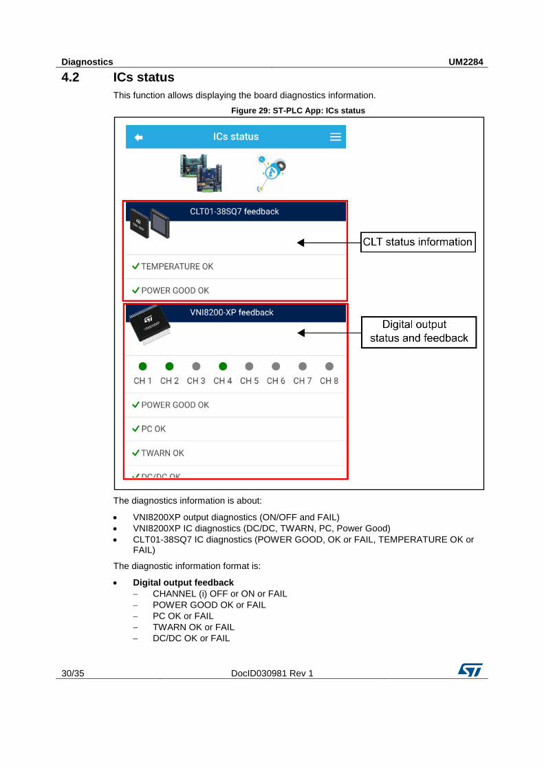
4.2 ICs status
This function allows displaying the board diagnostics information.
Figure 29: ST-PLC App: ICs status
The diagnostics information is about:
VNI8200XP output diagnostics (ON/OFF and FAIL)
VNI8200XP IC diagnostics (DC/DC, TWARN, PC, Power Good)
CLT01-38SQ7 IC diagnostics (POWER GOOD, OK or FAIL, TEMPERATURE OK or FAIL)
The diagnostic information format is:
Digital output feedback
CHANNEL (i) OFF or ON or FAIL
POWER GOOD OK or FAIL
PC OK or FAIL
TWARN OK or FAIL
DC/DC OK or FAIL
UM2284 Diagnostics
DocID030981 Rev 1 31/35
Digital input feedback
TEMPERATURE OK or FAIL
POWER GOOD OK or FAIL
The channel status is shown in 3 different colors:
Red: Channel Fault
Green: On
Gray: Off
The device must be connected to the X-NUCLEO expansion board to get Device Status Information.
ST-PLC App desktop version UM2284
32/35 DocID030981 Rev 1
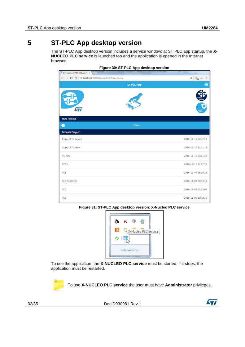
5 ST-PLC App desktop version
The ST-PLC App desktop version includes a service window: at ST PLC app startup, the X-NUCLEO PLC service is launched too and the application is opened in the Internet browser.
Figure 30: ST-PLC App desktop version
Figure 31: ST-PLC App desktop version: X-Nucleo PLC service
To use the application, the X-NUCLEO PLC service must be started; if it stops, the application must be restarted.
To use X-NUCLEO PLC service the user must have Administrator privileges.
UM2284
DocID030981 Rev 1 33/35
Appendix A Known issues/troubleshooting
1. Issue: After "X-Nucleo-PLC.exe" execution, the message "An error occurred. Try to restart application with Administrator Privileges" is shown. Solution: Start the application "X-Nucleo-PLC.exe" using administrator privileges.
2. Issue: The application does not correctly display images and other graphics. Solution: Check if the "X-Nucleo Service" started properly in TryIcon; if not, restart the application.
3. Issue: In the desktop version, after connecting the PC to the "Ladder Demo Board" network via a joint connection to the PLC (Test Connection, ICs status, Send Project) a timeout error is displayed. Solution: Try reinserting the wireless network password "Ladder Demo Board", wait for the reconnection and then retry.
4. Issue: The user is not able to connect via a mobile device to the PLC. Solution: To successfully connect to the PLC via a mobile device, disable the data connection.
UM2284
34/35 DocID030981 Rev 1
6 Revision history Table 3: Document revision history
Date Version Changes
13-Sep-2017 1 Initial release.
UM2284
DocID030981 Rev 1 35/35
IMPORTANT NOTICE – PLEASE READ CAREFULLY
STMicroelectronics NV and its subsidiaries (“ST”) reserve the right to make changes, corrections, enhancements, modifications , and improvements to ST products and/or to this document at any time without notice. Purchasers should obtain the latest relevant information on ST products before placing orders. ST products are sold pursuant to ST’s terms and conditions of sale in place at the time of order acknowledgement.
Purchasers are solely responsible for the choice, selection, and use of ST products and ST assumes no liability for application assistance or the design of Purchasers’ products.
No license, express or implied, to any intellectual property right is granted by ST herein.
Resale of ST products with provisions different from the information set forth herein shall void any warranty granted by ST for such product.
ST and the ST logo are trademarks of ST. All other product or service names are the property of their respective owners.
Information in this document supersedes and replaces information previously supplied in any prior versions of this document.
© 2017 STMicroelectronics – All rights reserved