Embed Size (px)
Citation preview
1
Project DEPLOY Grant Agreement 214158
“Industrial deployment of advanced system engineering methods for high productivity and dependability”
DEPLOY Deliverable D16
D2.1 Pilot Deployment in Transportation (WP2)
Public Document
September 11th 2009
http://www.deploy-project.eu
2
Contributors: Jerome Falampin ................................... Siemens Transportation Systems
Reviewers: Michael J Butler..................................................University of Southampton John Fitzgerald............................................................Newcastle University
3
Table of Contents
1 Abbreviations.............................................................................................................. 3 2 Introduction................................................................................................................. 3 3 Description of the pilot ............................................................................................... 3
3.1 System General Requirements............................................................................ 3 3.2 Description of the CBTC functions .................................................................... 3 3.3 Architecture......................................................................................................... 3 3.4 Hypotheses / constraints ..................................................................................... 3 3.5 CBTC chosen function: “Manage operating modes”.......................................... 3 3.6 Definitions........................................................................................................... 3 3.7 Informal description............................................................................................ 3 3.8 Safety properties of the function......................................................................... 3
4 Aims of the work ........................................................................................................ 3 4.1 Integration of event B development at Siemens Transportation Systems .......... 3
4.1.1 Current Siemens Transportation Systems project lifecyle.......................... 3 4.1.2 Proposed lifecycle including event-B ......................................................... 3
4.2 Comparison between lifecycle with/without event-B......................................... 3 4.2.1 Development:.............................................................................................. 3 4.2.2 Validation:................................................................................................... 3
4.3 Required activities/documents supporting an event-B project (development) ... 3 4.3.1 SRS ............................................................................................................. 3 4.3.2 SAS ............................................................................................................. 3 4.3.3 EFS.............................................................................................................. 3 4.3.4 Refinement Plan.......................................................................................... 3
4.4 Required activities/documents supporting an event-B project (validation)........ 3 4.4.1 PHA............................................................................................................. 3 4.4.2 Functional Safety analysis .......................................................................... 3
4.5 Standards............................................................................................................. 3 4.6 Safety demonstration and formal proof .............................................................. 3
5 Technical steps undertaken ......................................................................................... 3 5.1 Probabilities ........................................................................................................ 3
5.1.1 Need for event probabilities and invariant probabilities............................. 3 5.1.2 Difficulties with probabilities within event B models ................................ 3 5.1.3 Safety objective Allocation Principle ......................................................... 3 5.1.4 Safety properties Allocation Principle ........................................................ 3 5.1.5 Safety definition for an equipment ............................................................. 3 5.1.6 Reliability validation (HW) ........................................................................ 3 5.1.7 Reliability validation (SW) ......................................................................... 3
5.2 Use of probability within event-B models .......................................................... 3 5.2.1 Probability................................................................................................... 3 5.2.2 Properties .................................................................................................... 3 5.2.3 Events.......................................................................................................... 3 5.2.4 Combination of failures .............................................................................. 3 5.2.5 Common mode of failure ............................................................................ 3 5.2.6 Difficulties and improvements (to be investigated).................................... 3
4
5.3 FMEA ................................................................................................................. 3 5.4 Requirement traceability..................................................................................... 3
5.4.1 Traceability within event-B models............................................................ 3 5.4.2 Traceability proposal .................................................................................. 3
5.5 Validation of railway data................................................................................... 3 6 Results of the minipilot and pilot deployment............................................................ 3
6.1 Minipilot ............................................................................................................. 3 6.2 System requirements specification (SRS)........................................................... 3 6.3 Refinement plan .................................................................................................. 3 6.4 Example of pilot development: avoiding collision ............................................. 3
6.4.1 First refinement:.......................................................................................... 3 6.4.2 Second refinement: ..................................................................................... 3 6.4.3 Fifth refinement .......................................................................................... 3
7 Lessons learnt, feedback to Methods and Tools and towards full deployment .......... 3 7.1 Lessons learnt...................................................................................................... 3
7.1.1 Probabilities and failures............................................................................. 3 7.1.2 Requirements .............................................................................................. 3 7.1.3 Temporal constraints................................................................................... 3
7.2 Feedback to Methods and Tools ......................................................................... 3 7.2.1 UML2B....................................................................................................... 3 7.2.2 proB............................................................................................................. 3
7.3 Towards full deployment .................................................................................... 3 7.4 event-B model decomposition ............................................................................ 3
7.4.1 event-B model generation ........................................................................... 3 7.4.2 event-B to B translation .............................................................................. 3
8 Conclusion .................................................................................................................. 3 9 ANNEX : refinement plan .......................................................................................... 3
9.1 First refinement:.................................................................................................. 3 9.2 Second refinement : ............................................................................................ 3 9.3 Third refinement: ................................................................................................ 3 9.4 fourth refinement ................................................................................................ 3 9.5 fith refinement..................................................................................................... 3 9.6 6th refinement : ................................................................................................... 3 9.7 7th refinement : ................................................................................................... 3 9.8 Decomposition .................................................................................................... 3
9.8.1 Time ............................................................................................................ 3 9.8.2 Driver .......................................................................................................... 3 9.8.3 train ............................................................................................................. 3 9.8.4 Carborne controler (CC) ............................................................................. 3 9.8.5 Wayside controler (WC) ............................................................................. 3 9.8.6 Track ........................................................................................................... 3
5
1 Abbreviations
Abbreviation Definition ATPF Full Automatic Train Protection
ATC Automatic Train Control
ATO Automatic Train Operation
ATP Automatic Train Protection
ATPR Automatic Train Protection Restricted manual mode
ATS Automatic Train Supervision
Automaton State machine
CBTC Communication Based Train Control
CC Carborne Controller
EB Emergency Braking
EdithB Tool developed by STS, that automatically generates refinements of a B model
EFS Equipment Functional Specification
FMEA Failure Mode and Effects Analysis
FSA Functional Safety Analysis
FTA Fault Tree Analysis
HMI Human-Machine Interface
IXL Interlocking
MAL Movement Authority Limit
NV Non Vital
PHA Preliminary Hazard Analysis
RAMS Reliability, Availability, Maintainability, Safety
SAS System Architecture Specification
SIL Safety Integrity Level
SRS System Requirements Specification
STS Siemens Transportation Systems
TO Train Operator
V Vital
Vital Safety critical
ZC Zone Controller
6
2 Introduction WP2 is the transportation case study of the Deploy project, lead by Siemens Transportation Systems, in close cooperation with the following partners:
• Åbo Akademi and Newcastle University (collaboration with WP8, task 8.4 on stochastic reasoning)
• University of Southampton (review of the minipilot and pilot, work on decomposition and UML2B )
• Düsseldorf University (work on data proof) • ETH Zürich (training and work on stochastic reasoning)
Siemens Transportation Systems (STS) has considerable experience of applying formal methods to software components of railway systems. For DEPLOY the challenge is to raise this to the level of overall systems in order to address system safety. Event-B would thus involve new people, system engineers, without any background in formal methods. To deploy event-B into the transportation industry, the following development strategy has been pursued:
• Minipilot: The minipilot is a small event-B model, focused on specific aspects (in the WP2 case, timing issues and probability)
• Pilot: The pilot's aim is to define an industrial process (necessary for large scale deployment) and bring evidences for sector acceptance (by developing a representative model of a railway system)
• Full-deployment: The full-deployment will result in a complete development (from system level to software level) of a railway function.
The purpose of this deliverable is to provide the results of the minipilot and the pilot, and in particular:
• formal model of a subset of the TrainGuard control (see example section 6.4)
• a specification of the automatic generation of the formal software model (RODIN2B tool is almost finished, and will enable translation from event-B model to classical B models supported by AtelierB, see section 7.4.2)
• validation result (see validation process section 4.4) The chosen system for the minipilot, pilot and full-deployment is the Communication Based Train Control (CBTC), which is commercially used in New York, and will be used for future projects (Paris line1,3,5 ; Budapest line 2 & 4, Sao Paulo Line 4, Barcelona line 9, Helsinki...)
7
3 Description of the pilot
3.1 System General Requirements The Trainguard MT CBTC system allows an uninterrupted service (7/7 days, 24/24 hours). The System is intended to cope with:
• mixed traffic (traffic with CBTC equipped and non-equipped trains) • mixed operation (same as mixed traffic, but unequipped trains are also
used for passengers transportation) for example in case of interconnected lines or progressive refurbishment of the signaling system of an existing line (migration phase). The Trainguard MT CBTC system also considers heterogeneous fleets:
• Trains with various lengths • Trains with various mechanical characteristics (rolling stock interface,
servo control, presence of a free axle…) • Trains with various performances • Work trains
The CBTC system is a functionally integrated train command, control and management system to equip main tracks, turnback tracks, sidings and depots of a “metro” rail system. The CBTC system shall perform functions related to:
• the safety of train movement in order to prevent derailment and collisions, • manual/ automatic driving between stations (with train operator inside), • train regulation, • safety of passengers and staff in the trains and on station platforms.
In the CBTC system, all the functions are classified, according to their involvement with safety into Safety Integrity Levels (SILs), All the system functions classified SIL 4 or SIL 3 have to be implemented in a vital software and/or on a vital hardware: In the vital software,the design is based on the following:
• Use of the vital coding technique for random failures during the compilation and the execution of the software. It ensures that errors in the production chain and hardware failures are detected. It ensures that the undetected error probability is below the required level of safety.
• Use of B method for software development. In the vital hardware, the design is based on the use of inherent fail-safe design in the non digital hardware board
8
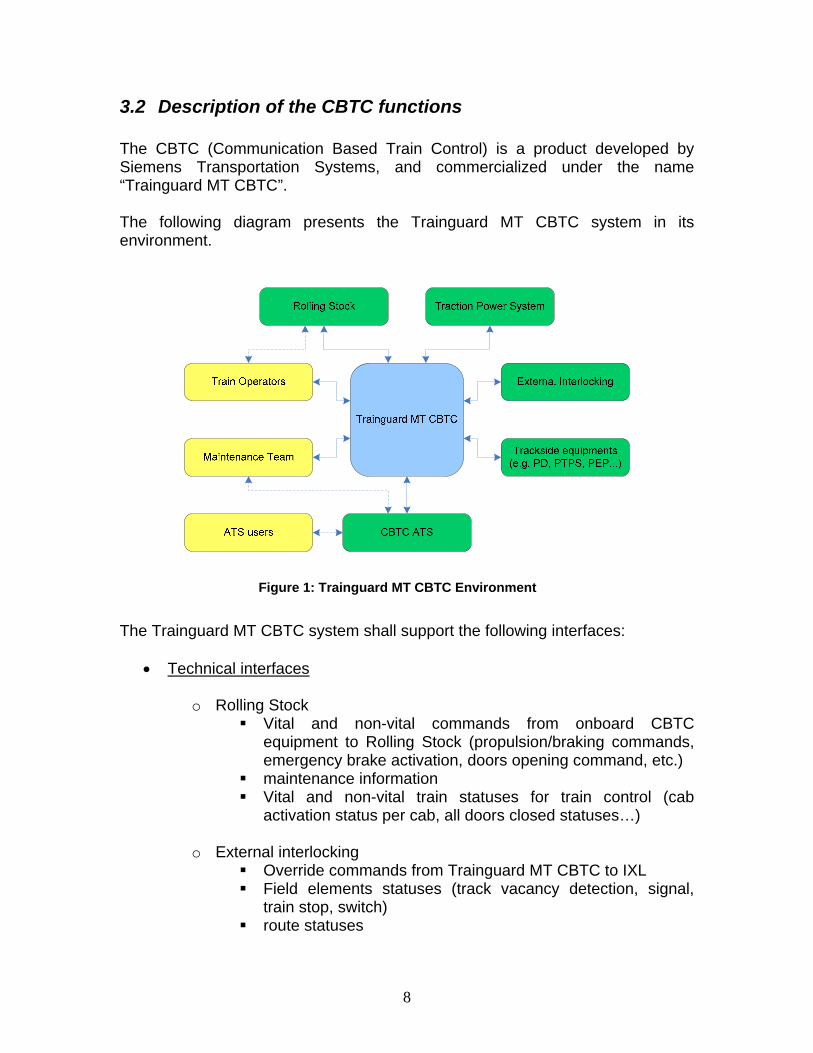
3.2 Description of the CBTC functions The CBTC (Communication Based Train Control) is a product developed by Siemens Transportation Systems, and commercialized under the name “Trainguard MT CBTC”. The following diagram presents the Trainguard MT CBTC system in its environment.
Figure 1: Trainguard MT CBTC Environment
The Trainguard MT CBTC system shall support the following interfaces:
• Technical interfaces
o Rolling Stock Vital and non-vital commands from onboard CBTC
equipment to Rolling Stock (propulsion/braking commands, emergency brake activation, doors opening command, etc.)
maintenance information Vital and non-vital train statuses for train control (cab
activation status per cab, all doors closed statuses…)
o External interlocking Override commands from Trainguard MT CBTC to IXL Field elements statuses (track vacancy detection, signal,
train stop, switch) route statuses
9
o CBTC Automatic Train Supervision (ATS) Automatic Train Control (ATC) to ATS remote monitoring for
Supervision, Operation and Maintenance ATC to ATS remote monitoring for Centralized Event Data
(for further use of the ATS Store & retrieval functionalities) ATC to ATS train position report for ATS tracking Vital and non-vital ATS to ATC remote controls for train
movement control facilities (automatic trip management, automatic route management, automatic train regulation, temporary speed restrictions set or removal, alarm management, ATS time management, etc.)
o Trackside equipments
Platform Track Protection System, Platform Emergency Plungers, Punctual Detectors
o Traction Power System
Electrical section status (energized or not) Traction power shutdown in case of suspicion of passenger
on the track • Interface to operation
o Train Operator
via Train Operator Human-Machine Interface (HMI) via train operator commands (cab activation, driving mode
selector, train start…) part of the Rolling Stock interface
o ATS user (via CBTC-ATS interface) operator commands ATS user data for operation and supervision
• Interface to maintenance
o Via CBTC-ATS interface
Maintenance supervision Event data recorder (centralized)
o Directly on a given CBTC equipment
Event data recorder (embedded in CBTC equipments)
10
•
3.3 Architecture The structure of TGMT CBTC system is composed of four main parts:
1. TGMT CBTC on-board ATC subsystem, CC (Carborne Controller). Every train
unit is equipped with a CC which:
• supervises and controls the train movement,
• provides a representation of the train for ATS supervision and central service and diagnosis,
2. TGMT CBTC wayside ATC subsystem, including a ZC (Zone Controller). The
equipped network is divided into one or several zones (depending on its length and complexity), each one equipped with a ZC.
The ZC: • protects train movement
• is the central point where the track data base (logical representation) of the ZC controlled area (is inserted in the system and provides this track data base to the trains,
• is the central point where the speed restrictions are managed for the ZC controlled area.
3. TGMT CBTC ATS subsystem :
• provides a central entry point for ATS controls onto the trains.
The main criteria, which have been taken into account for the design of the system are the following:
• Limit the impact of a complete wayside failure onto the overall train movements. Trains pass the failed area in a restricted driving mode and resume normal mode once reaching the following operational zone.
• Operate at decentralized level even in case of complete loss of central ATS system.
• Interface to external devices that are spread out along the entire line.
11
• Have a functional split between track related and interlocking related functions on the one hand and train related functions on the other hand (which limits computing effort of each machine and reduce amount of data to be exchanged, e.g. no need to exchange data between different trains).
• Allow interoperability and interchangeability with external provider's equipment. Since the product shall be used for different project, interoperability and interchangeability for the product means strict definition of the sub-system interfaces.
o Interoperability is a way to operate a network where:
An equipped train provided by Siemens Transportation Systems can run on an equipped track supplied by another company
An equipped train provided by Siemens Transportation Systems can be coupled with a train supplied by another company
A portion of track equipped by Siemens Transportation Systems and an adjacent track supplied by another company can be interfaced with a common Operation Control Centre
A train equipped by STS or another company can pass several boundaries (STS/ another company) without any operational or technical disturbance.
o Interchangeability allows the replacement of a STS component by an equivalent component provided by another provider. The list of interchangeable components is as follows:
The ATS
The Trackside sub assembly (ZC and associated hardware)
The on-board sub assembly (CC and associated hardware)
3.4 Hypotheses / constraints On CBTC equipments, the main functions are realized by cyclic software. This software has a cycle time of about 300ms, so the inputs are watched every 300ms, and the outputs are emitted 300ms after the corresponding input. The controller does not get the inputs continuously, but gets inputs every 300ms. This means, for instance, that the driver may select a mode with the driving console switch, but the carborne controller will get this input with a delay (300ms after the driver switched, at the latest). The outputs of the software (EB, control
12
mode,...) are issued within 300ms after getting the input (selected mode on the driving console switch, status mode of the train). Due to this constraint, the safety properties cannot all be proven to hold at all times: a driver may select a forbidden mode and then return to the previous mode within 300ms, without any reaction of the system. This implies that assumptions should be made explicit about the driver's behaviour, and that there should be a distinction between a safety property (absence of derailment and collision) and a "safety related" property (selection of an authorized mode).
3.5 CBTC chosen function: “Manage operating modes” This function was chosen for the minipilot, pilot and full deployment because:
• It involves all equipments (CC, ZC, ATS, IXL, train) of a railway system. • Experience gained on a previous project suggested that this function is
difficult to reuse • It involves human behaviour (driver)
The major goal of the controller function “Manage operating modes“ is to determine the train control mode according to driving console switch and the train position on the line. "Manage operating modes" is divided into the following sub-functions:
• Determine train operating mode
• Determine train status mode
• Determine train control mode The function “Determine train operating mode” determines the train operating mode according to a switch on the driving console. The function “Determine train status mode” determines whether the geographical position of the train allows full ATP mode. The function “Determine train control mode” determines the train control mode.
3.6 Definitions Operating modes: There are three operating modes on the driving console switch: Full ATP (ATPF = Full Automatic Train Protection) ATPR (Automatic Train Protection Restricted) Bypass (CBTC is bypassed) These operating modes are selected manually by the train driver. Territory: The subway network is divided into two kinds of territories: CBTC territory: network area where full ATP mode is authorized
13
Non CBTC territory: network area with no CBTC equipment where ATPR is the normal mode. Full ATP mode is forbidden. Control modes: There are three control modes considered by the carborne controller: Full ATP (ATPF = Full Automatic Train Protection) ATPR (Automatic Train Protection Restricted) Bypass (CBTC outputs are bypassed) These control modes are determined by the controller. Emergency Brake (EB): EB = Emergency brake EB can be triggered (train is braking) or not triggered. EB triggered is considered as a safe state.
3.7 Informal description The full ATP control mode allows driver or driverless mode, and is available only on CBTC territory. When the controller does not know the position of the train on the line, it assumes that it is outside of the CBTC territory: therefore, the ATP control mode is not authorized, even if the actual position of the train is on the CBTC territory (in that case, the carborne controller will trigger the emergency brake) . ATPR control mode is authorized anywhere, anytime. ATPR provides a restricted protection (train speed is limited to 25km/h), the train is under driver’s responsibility. Bypass control mode is authorized anywhere, anytime. When bypass is selected, the outputs of the CBTC are bypassed, but the controller triggers the EB output, just to be on the safe side. In bypass mode, the train is under driver’s full responsibility. When a train in APTF control mode moves from CBTC territory to non-CBTC territory, the carborne controller shall trigger the emergency brake The driver can select any mode, anywhere, anytime. The controller shall protect the train (EB triggered, no control mode change) if the driver endangers the train by selecting or being in a wrong mode.
3.8 Safety properties of the function Bypass mode selected on the driving console switch shall result in a triggered EB. In case of Full ATP mode selected on the driving console switch while the train is on a non CBTC territory, the control mode shall be ATPR.
14
Any discrepancies between selected operating mode and control mode shall result in a triggered EB. As a consequence of the two previous properties: Full ATP mode selection on the driving console switch while the train is on a non-CBTC territory shall result in a triggered EB. The initialization control mode is ATPR. The driving console switch is vital: the controller sees the actual selected operating mode, and operates accordingly to the indicated position of the switch.
15
4 Aims of the work The acceptance of event-B at Siemens Transportation Systems rely on
- evidence that a large scale event-B development is feasible (pilot and full deployment)
- an industrial process that supports event-B development - a safety validation of the system developed with event-B - compliance with CENELEC standards
The pilot results are discussed in section 6. This section deals with the three last items.
4.1 Integration of event B development at Siemens Transportation Systems
Siemens Transportation Systems has been using B method for more than 15 years, and a considerable investment has been made in tools and methods. In particular, an automatic refinement tool has been developed to allow the (almost) automatic production of the concrete B model from the abstract B model. It is therefore important that the use of event-B at system level does not impose new investments at software level.
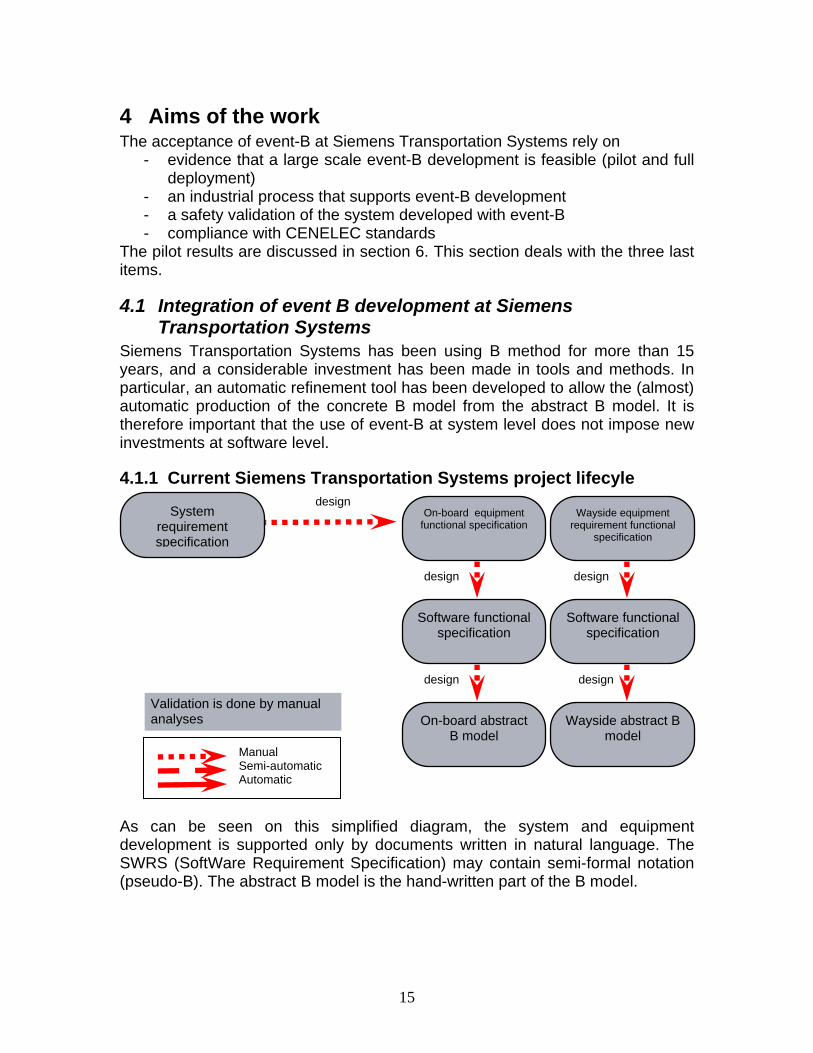
4.1.1 Current Siemens Transportation Systems project lifecyle
As can be seen on this simplified diagram, the system and equipment development is supported only by documents written in natural language. The SWRS (SoftWare Requirement Specification) may contain semi-formal notation (pseudo-B). The abstract B model is the hand-written part of the B model.
System requirement specification
design
Manual Semi-automatic Automatic
On-board equipment functional specification
Wayside equipment requirement functional
specification
Software functional specification
Software functional specification
On-board abstract B model
Wayside abstract B model
design
design
design
design
Validation is done by manual analyses
16
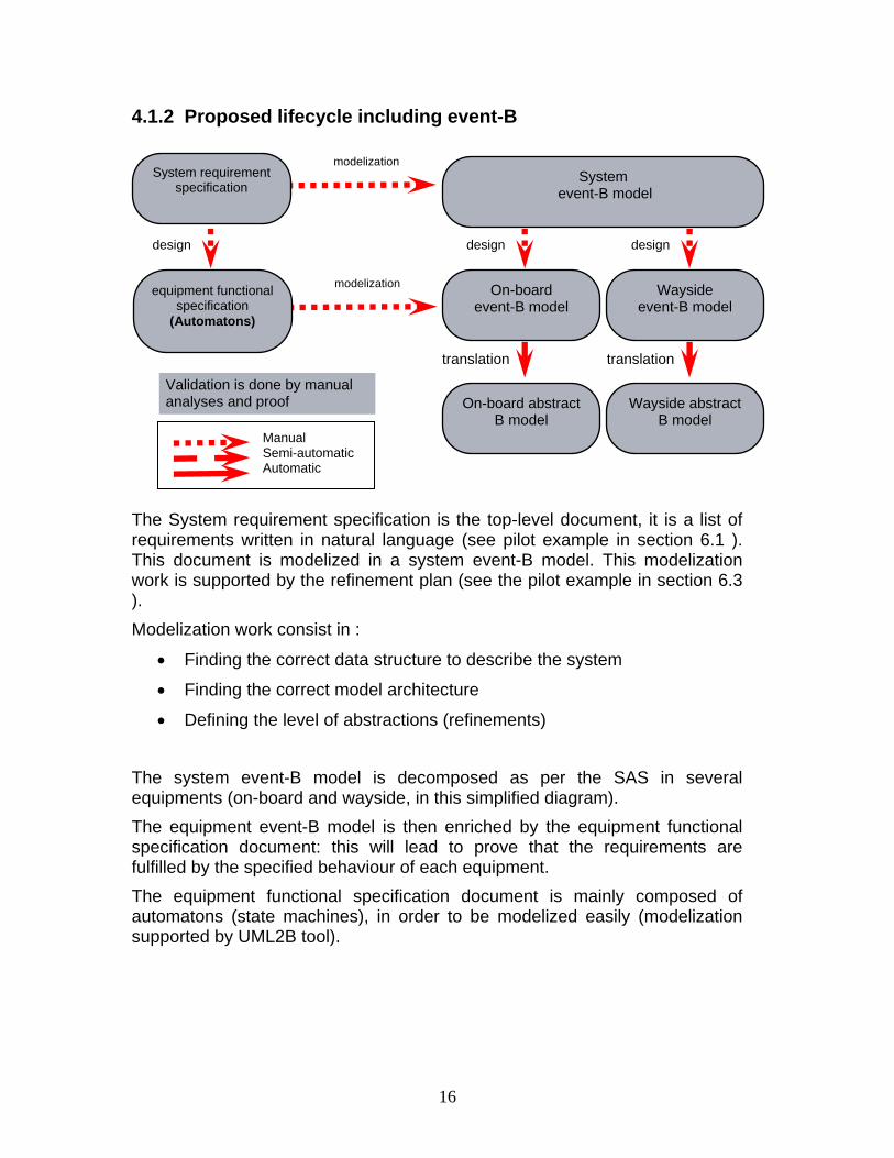
4.1.2 Proposed lifecycle including event-B
The System requirement specification is the top-level document, it is a list of requirements written in natural language (see pilot example in section 6.1 ). This document is modelized in a system event-B model. This modelization work is supported by the refinement plan (see the pilot example in section 6.3 ). Modelization work consist in :
• Finding the correct data structure to describe the system
• Finding the correct model architecture
• Defining the level of abstractions (refinements) The system event-B model is decomposed as per the SAS in several equipments (on-board and wayside, in this simplified diagram). The equipment event-B model is then enriched by the equipment functional specification document: this will lead to prove that the requirements are fulfilled by the specified behaviour of each equipment. The equipment functional specification document is mainly composed of automatons (state machines), in order to be modelized easily (modelization supported by UML2B tool).
System requirement specification
modelization
Manual Semi-automatic Automatic
System event-B model
On-board event-B model
Wayside event-B model
On-board abstract B model
Wayside abstract B model
design
translation
design
translation
equipment functional specification
(Automatons)
modelization
design
Validation is done by manual analyses and proof
17
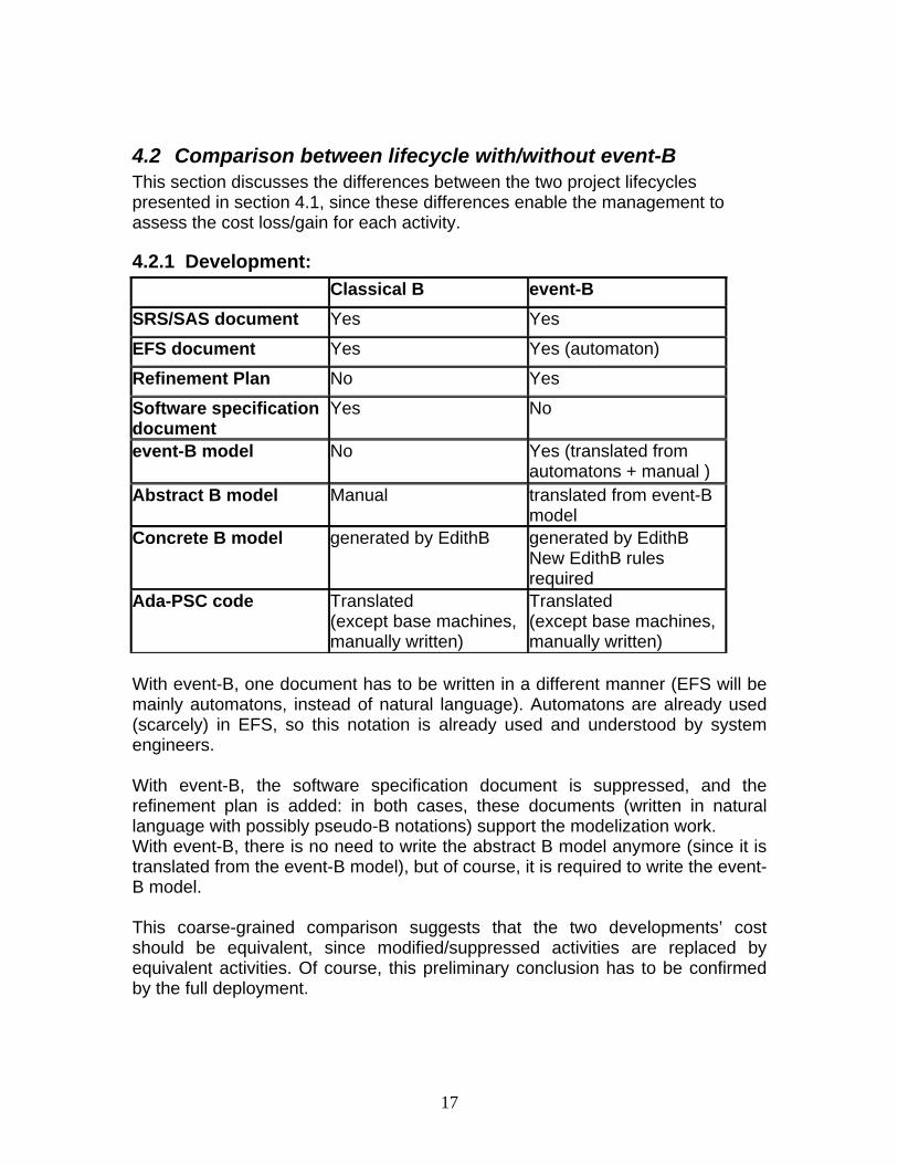
4.2 Comparison between lifecycle with/without event-B This section discusses the differences between the two project lifecycles presented in section 4.1, since these differences enable the management to assess the cost loss/gain for each activity.
4.2.1 Development: Classical B event-B
SRS/SAS document Yes Yes
EFS document Yes Yes (automaton)
Refinement Plan No Yes
Software specification document
Yes No
event-B model No Yes (translated from automatons + manual )
Abstract B model Manual translated from event-B model
Concrete B model generated by EdithB generated by EdithB New EdithB rules required
Ada-PSC code Translated (except base machines, manually written)
Translated (except base machines, manually written)
With event-B, one document has to be written in a different manner (EFS will be mainly automatons, instead of natural language). Automatons are already used (scarcely) in EFS, so this notation is already used and understood by system engineers. With event-B, the software specification document is suppressed, and the refinement plan is added: in both cases, these documents (written in natural language with possibly pseudo-B notations) support the modelization work. With event-B, there is no need to write the abstract B model anymore (since it is translated from the event-B model), but of course, it is required to write the event-B model. This coarse-grained comparison suggests that the two developments’ cost should be equivalent, since modified/suppressed activities are replaced by equivalent activities. Of course, this preliminary conclusion has to be confirmed by the full deployment.
18
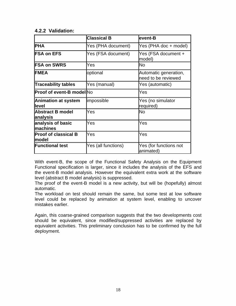
4.2.2 Validation: Classical B event-B
PHA Yes (PHA document) Yes (PHA doc + model)
FSA on EFS Yes (FSA document) Yes (FSA document + model)
FSA on SWRS Yes No
FMEA optional Automatic generation, need to be reviewed
Traceability tables Yes (manual) Yes (automatic)
Proof of event-B model No Yes
Animation at system level
impossible Yes (no simulator required)
Abstract B model analysis
Yes No
analysis of basic machines
Yes Yes
Proof of classical B model
Yes Yes
Functional test Yes (all functions) Yes (for functions not animated)
With event-B, the scope of the Functional Safety Analysis on the Equipment Functional specification is larger, since it includes the analysis of the EFS and the event-B model analysis. However the equivalent extra work at the software level (abstract B model analysis) is suppressed. The proof of the event-B model is a new activity, but will be (hopefully) almost automatic. The workload on test should remain the same, but some test at low software level could be replaced by animation at system level, enabling to uncover mistakes earlier. Again, this coarse-grained comparison suggests that the two developments cost should be equivalent, since modified/suppressed activities are replaced by equivalent activities. This preliminary conclusion has to be confirmed by the full deployment.
19
4.3 Required activities/documents supporting an event-B project (development)
4.3.1 SRS The SRS (System Requirement Specification) is a list of requirements, written in natural language (no formal notation, few/no diagrams). A SRS has been written for the pilot, and is included in this document (see section 6.1).
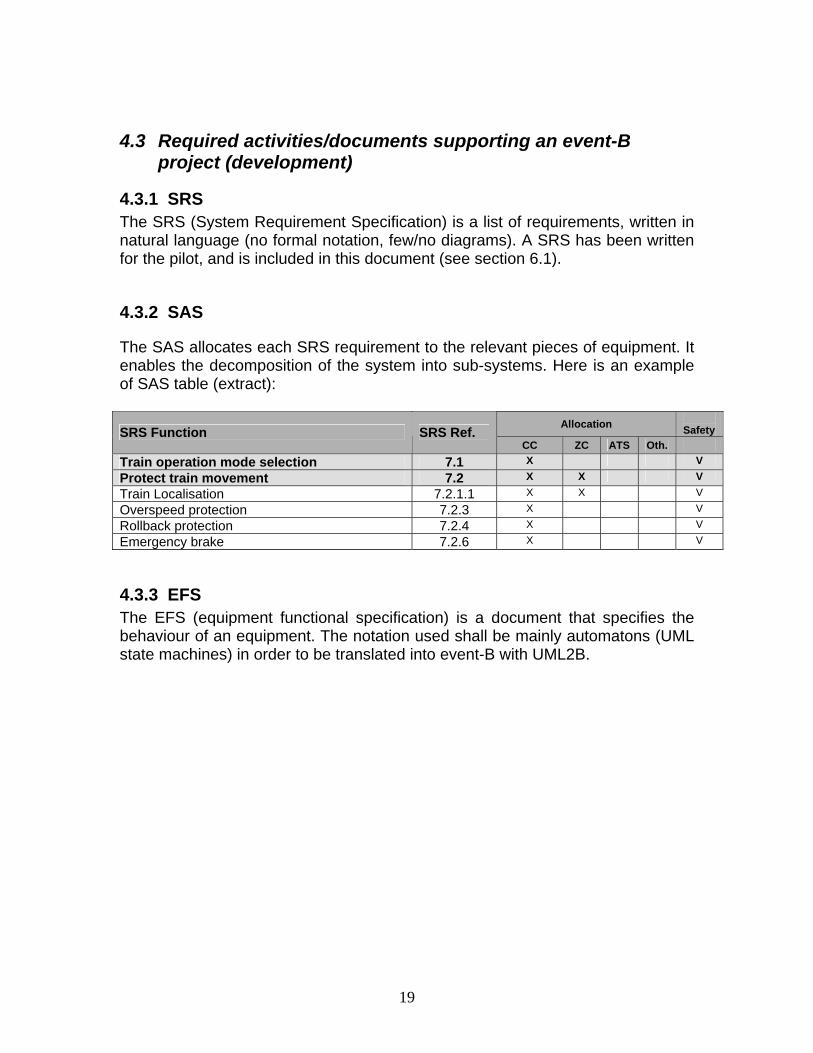
4.3.2 SAS
The SAS allocates each SRS requirement to the relevant pieces of equipment. It enables the decomposition of the system into sub-systems. Here is an example of SAS table (extract):
Allocation Safety SRS Function SRS Ref.
CC ZC ATS Oth. Train operation mode selection 7.1 X V
Protect train movement 7.2 X X V
Train Localisation 7.2.1.1 X X V
Overspeed protection 7.2.3 X V
Rollback protection 7.2.4 X V
Emergency brake 7.2.6 X V
4.3.3 EFS The EFS (equipment functional specification) is a document that specifies the behaviour of an equipment. The notation used shall be mainly automatons (UML state machines) in order to be translated into event-B with UML2B.
20
4.3.4 Refinement Plan The refinement plan is a document that provides modelization choices and abstraction ordering of the requirements (from the SRS), in order to help the modelization and the proof. The refinement plan is complete when each requirement of the SRS is taken into account in the refinement plan. A requirement of the SRS can be split into several sub-requirement, generalized in a more abstract property, rephrased, etc.
4.4 Required activities/documents supporting an event-B project (validation)
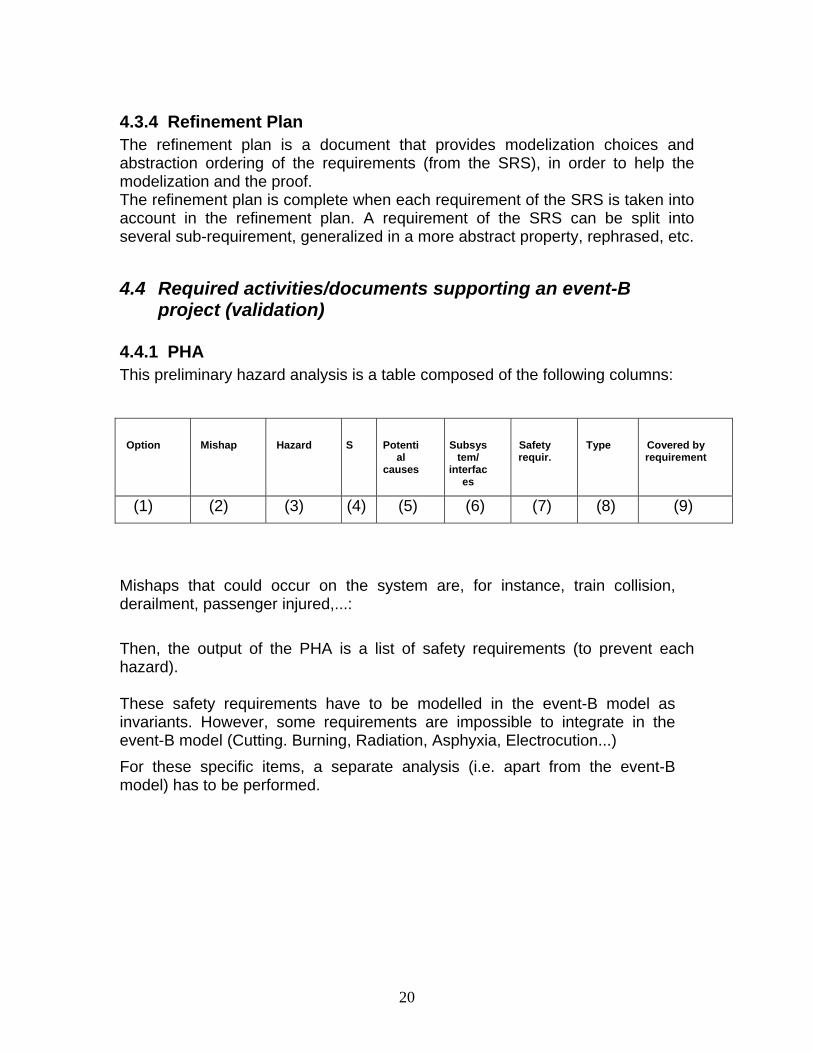
4.4.1 PHA This preliminary hazard analysis is a table composed of the following columns:
Option
Mishap
Hazard
S
Potential
causes
Subsystem/
interfaces
Safety requir.
Type
Covered by requirement
(1) (2) (3) (4) (5) (6) (7) (8) (9)
Mishaps that could occur on the system are, for instance, train collision, derailment, passenger injured,...: Then, the output of the PHA is a list of safety requirements (to prevent each hazard). These safety requirements have to be modelled in the event-B model as invariants. However, some requirements are impossible to integrate in the event-B model (Cutting. Burning, Radiation, Asphyxia, Electrocution...) For these specific items, a separate analysis (i.e. apart from the event-B model) has to be performed.
21
4.4.2 Functional Safety analysis Phase 1 For each functional safety analysis: Identify the functions from the Equipment specification Identify the environmental constraints Phase 2 Recall the PHA safety requirements (Hazardous situations) Phase 3 For each class of hazard, determination of detailed hazardous situations (tree format) Phase 4 For each terminal event of the tree diagram, detailed analysis is done:
• through an event-B model analysis, a traceability table is issued to show how the hazardous event is covered by the invariants, guards etc. If the proof is not feasible, the specification/model has to be changed.
• if additional criteria are necessary, they are pointed out as below : o Software criteria
o Dimension criteria
o Hardware criteria
o O&M criteria
o External system criteria (Rolling Stock, …)
4.5 Standards The applicable standards at software level (CENELEC EN 50128) mention that formal methods (and in particular B) are "highly recommended" for safety critical software and specification, but no process or activities are described to define how to use formal methods. At system level, formal methods are not mentioned at all. This means that there is currently no informative or normative chapter about formal methods in Cenelec Standards, and a railway industrialist has to define a process that is acceptable to both the customer and certification bodies.
4.6 Safety demonstration and formal proof The complete list of safety properties gives a formal definition of safety, whereas very often (both in contracts and technical documents) safety definition is implicit and/or vague: it is usually encapsulated in a phrase like "the system shall not cause injuries nor fatalities". However, a railway system cannot fulfil that requirement in all circumstances: earthquake, terrorism, vandalism, etc may cause accidents that cannot be avoided. So one of the
22
main outputs of the modelization is agreement on a common, explicit and formal definition of safety between all partners of a project: customer, co-contractors, sub-contractors, certification bodies, transportation authorities.... Then, once safety is formally defined, the aim of the model is to prove the safety properties. This implies that the model shall also contain all possible failures, in order to prove the safety properties in all cases, including degraded modes, combination of failures, etc. But with failures (for instance, loss of the brakes), it appears that safety properties don't hold anymore. And, indeed, the goal of the safety validation is not to demonstrate that no combination of errors can lead to an unsafe situation: The goal is to show that all combinations of errors leading to unsafe situations are improbable. Therefore, we have to introduce probabilities of failures and set up a safety critical objective: the typical value for that is "unsafe situation rate < 10^-9/h" The proof of the model ensures that this objective is met, in all modelized cases.
23
5 Technical steps undertaken It appeared early (during the minipilot development, see section 6.1) that some topics had to be studied for future large scale development:
• Probabilities and FMEA (to model failures)
• Data validation (to handle future decomposition of the system into many sub-systems)
These topics are addressed in this section.
5.1 Probabilities
5.1.1 Need for event probabilities and invariant probabilities event-B models are well adapted to system modeling, in order to formally prove that a set of properties (including safety properties) always hold. However, event-B modeling is not yet adapted to systems where properties (including safety properties) shall hold in "most cases", and where it is accepted to violate the system properties, providing that it is demonstrated that the probability of these violations are lower than a very low rate (for instance, in railway systems, unsafe situations are accepted, providing that the probability of such unsafe situation is lower that 10^-10/h). In other words, each safety property is associated to an acceptable probability of violation of the property. This "acceptable probability of violation of the property" is given by standards, such as EN50128/EN50129/EN50126 for railways applications.
5.1.2 Difficulties with probabilities within event B models First, it is not always possible to calculate the exact probability of occurrence of an event. Usually, failure rate is known, but the frequency of use can only be estimation. This is why categories of probabilities are used. Even with all probabilities available, introducing probabilities would necessitate the introduction of floating point numbers in the model, which may lead to proof difficulties. Here again, it seems better to use probability categories rather than actual probability figures.
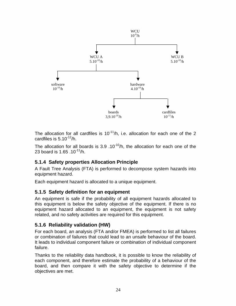
5.1.3 Safety objective Allocation Principle For a WCU (Wayside Control Unit), the safety objective is 10-9/h (maximum unsafe situation rate). The WCU objective has to be decomposed into objectives for equipments, boards, and finally components. An example of decomposition of objective is represented by the following figure:
24
WCU10-9/h
WCU A5.10-10/h
software10-10/h
hardware4.10-10/h
cardfiles10-11/h
boards3,9.10-10/h
WCU B5.10-10/h
The allocation for all cardfiles is 10-11/h, i.e. allocation for each one of the 2 cardfiles is 5.10-12/h. The allocation for all boards is 3.9 .10-10/h, the allocation for each one of the 23 board is 1.65 .10-11/h.
5.1.4 Safety properties Allocation Principle A Fault Tree Analysis (FTA) is performed to decompose system hazards into equipment hazard. Each equipment hazard is allocated to a unique equipment.
5.1.5 Safety definition for an equipment An equipment is safe if the probability of all equipment hazards allocated to this equipment is below the safety objective of the equipment. If there is no equipment hazard allocated to an equipment, the equipment is not safety related, and no safety activities are required for this equipment.
5.1.6 Reliability validation (HW) For each board, an analysis (FTA and/or FMEA) is performed to list all failures or combination of failures that could lead to an unsafe behaviour of the board. It leads to individual component failure or combination of individual component failure. Thanks to the reliability data handbook, it is possible to know the reliability of each component, and therefore estimate the probability of a behaviour of the board, and then compare it with the safety objective to determine if the objectives are met.
25
5.1.7 Reliability validation (SW) The development/validation process guarantees that the source code (B model) is safe. The source code unsafe behaviour probability is zero. The execution of the software may lead to wrong results even without hardware failure (electromagnetic fields, for instance). An analysis of the Vital Coded Processor gives a probability of 10-10/h for this hazard.
5.2 Use of probability within event-B models
In this section, we are making a proposal for an approach to the modelling of probability classes in event-B models suitable for the purposes of the STS pilot study.
5.2.1 Probability
A global variable P is defined in the model. This variable is initialized at zero, and is decremented by the events.
5.2.2 Properties
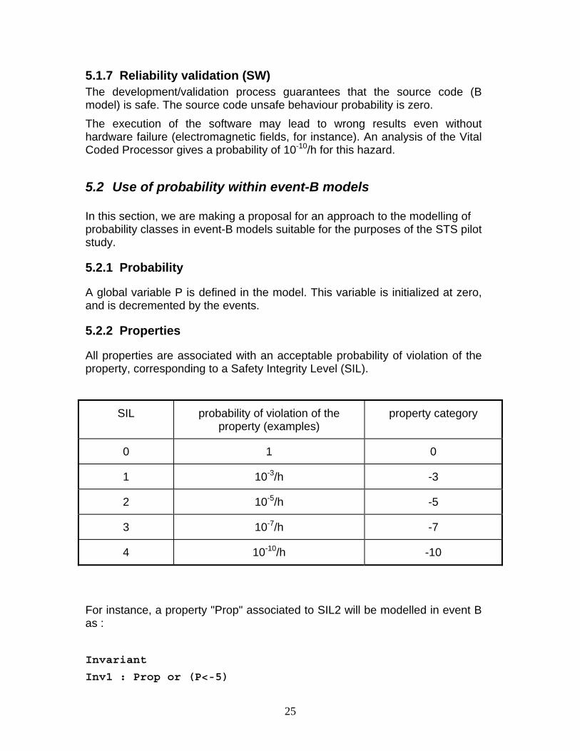
All properties are associated with an acceptable probability of violation of the property, corresponding to a Safety Integrity Level (SIL).
SIL probability of violation of the property (examples)
property category
0 1 0
1 10-3/h -3
2 10-5/h -5
3 10-7/h -7
4 10-10/h -10
For instance, a property "Prop" associated to SIL2 will be modelled in event B as : Invariant
Inv1 : Prop or (P<-5)
26
The proof will ensure that the property Prop is true, except in some cases for which the probability lower than 10-5/h
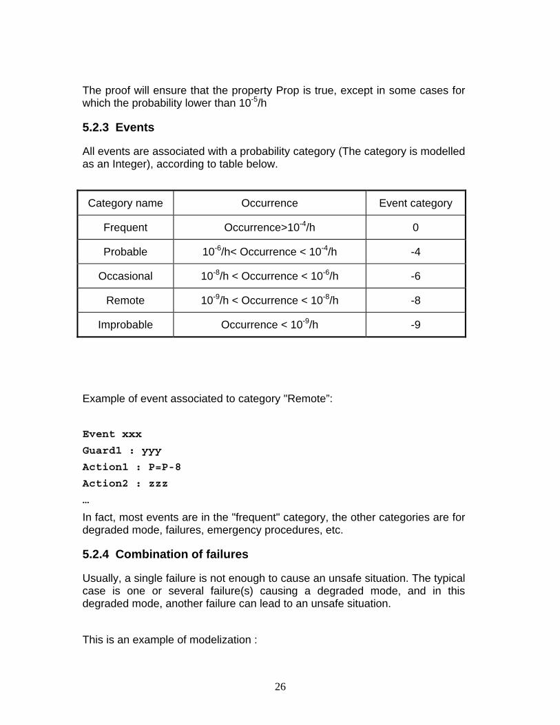
5.2.3 Events
All events are associated with a probability category (The category is modelled as an Integer), according to table below.
Example of event associated to category "Remote”: Event xxx
Guard1 : yyy
Action1 : P=P-8
Action2 : zzz
…
In fact, most events are in the "frequent" category, the other categories are for degraded mode, failures, emergency procedures, etc.
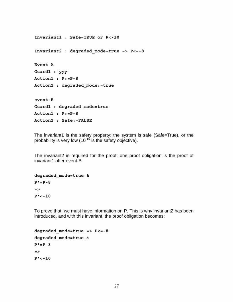
5.2.4 Combination of failures
Usually, a single failure is not enough to cause an unsafe situation. The typical case is one or several failure(s) causing a degraded mode, and in this degraded mode, another failure can lead to an unsafe situation. This is an example of modelization :
Category name Occurrence Event category
Frequent Occurrence>10-4/h 0
Probable 10-6/h< Occurrence < 10-4/h -4
Occasional 10-8/h < Occurrence < 10-6/h -6
Remote 10-9/h < Occurrence < 10-8/h -8
Improbable Occurrence < 10-9/h -9
27
Invariant1 : Safe=TRUE or P<-10
Invariant2 : degraded_mode=true => P<=-8
Event A Guard1 : yyy Action1 : P:=P-8 Action2 : degraded_mode:=true event-B
Guard1 : degraded_mode=true
Action1 : P:=P-8 Action2 : Safe:=FALSE The invariant1 is the safety property: the system is safe (Safe=True), or the probability is very low (10-10 is the safety objective). The invariant2 is required for the proof: one proof obligation is the proof of invariant1 after event-B: degraded_mode=true &
P'=P-8
=>
P'<-10
To prove that, we must have information on P. This is why invariant2 has been introduced, and with this invariant, the proof obligation becomes: degraded_mode=true => P<=-8
degraded_mode=true &
P'=P-8
=>
P'<-10
28
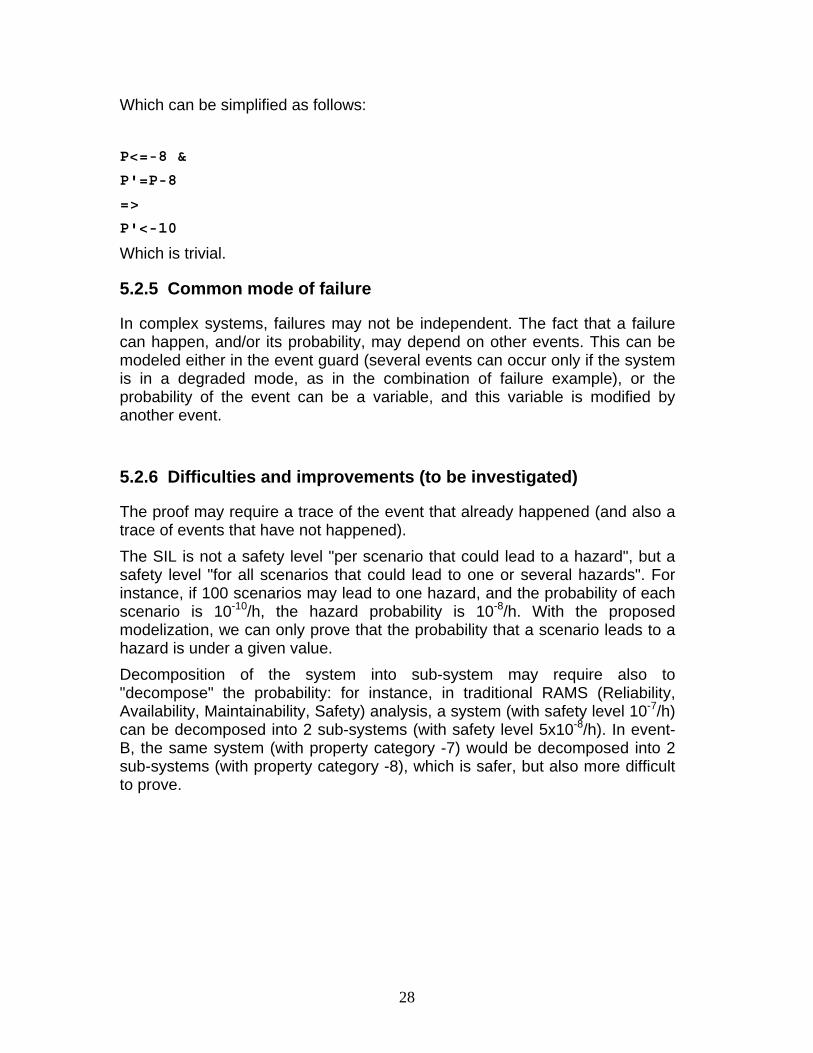
Which can be simplified as follows: P<=-8 &
P'=P-8
=>
P'<-10
Which is trivial.
5.2.5 Common mode of failure
In complex systems, failures may not be independent. The fact that a failure can happen, and/or its probability, may depend on other events. This can be modeled either in the event guard (several events can occur only if the system is in a degraded mode, as in the combination of failure example), or the probability of the event can be a variable, and this variable is modified by another event.
5.2.6 Difficulties and improvements (to be investigated)
The proof may require a trace of the event that already happened (and also a trace of events that have not happened). The SIL is not a safety level "per scenario that could lead to a hazard", but a safety level "for all scenarios that could lead to one or several hazards". For instance, if 100 scenarios may lead to one hazard, and the probability of each scenario is 10-10/h, the hazard probability is 10-8/h. With the proposed modelization, we can only prove that the probability that a scenario leads to a hazard is under a given value. Decomposition of the system into sub-system may require also to "decompose" the probability: for instance, in traditional RAMS (Reliability, Availability, Maintainability, Safety) analysis, a system (with safety level 10-7/h) can be decomposed into 2 sub-systems (with safety level 5x10⁻⁸/h). In event-B, the same system (with property category -7) would be decomposed into 2 sub-systems (with property category -8), which is safer, but also more difficult to prove.
29
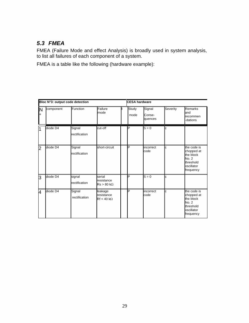
5.3 FMEA FMEA (Failure Mode and effect Analysis) is broadly used in system analysis, to list all failures of each component of a system. FMEA is a table like the following (hardware example):
Bloc N°3: output code detection CESA hardware
N°
component Function Failure mode
l Study
mode
Signal
Conse-quences
Severity Remarks and recommen-dations
1 diode D4 Signal
rectification
cut-off P S = 0 c
2 diode D4 Signal
rectification
short-circuit P incorrect code
c the code is chopped at the block No. 2 threshold oscillator frequency
3 diode D4 signal
rectification
serial resistance Rs > 80 kΩ
P S = 0 c
4 diode D4 Signal
rectification
leakage resistance Rf < 40 kΩ
P incorrect code
c the code is chopped at the block No. 2 threshold oscillator frequency
30
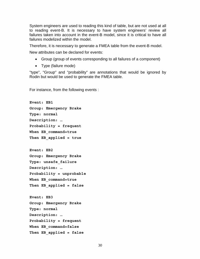
System engineers are used to reading this kind of table, but are not used at all to reading event-B. It is necessary to have system engineers’ review all failures taken into account in the event-B model, since it is critical to have all failures modelized within the model. Therefore, it is necessary to generate a FMEA table from the event-B model. New attributes can be declared for events:
• Group (group of events corresponding to all failures of a component)
• Type (failure mode) "type", "Group" and "probability" are annotations that would be ignored by Rodin but would be used to generate the FMEA table. For instance, from the following events : Event: EB1
Group: Emergency Brake
Type: normal
Description: …
Probability = frequent
When EB_command=true
Then EB_applied = true
Event: EB2
Group: Emergency Brake
Type: unsafe_failure
Description: …
Probability = unprobable
When EB_command=true
Then EB_applied = false
Event: EB3
Group: Emergency Brake
Type: normal
Description: …
Probability = frequent
When EB_command=false
Then EB_applied = false
31
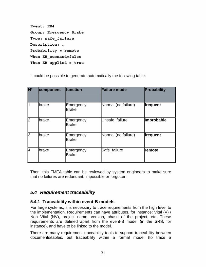
Event: EB4
Group: Emergency Brake
Type: safe_failure
Description: …
Probability = remote
When EB_command=false
Then EB_applied = true
It could be possible to generate automatically the following table:
N° component function Failure mode Probability
1 brake Emergency Brake
Normal (no failure) frequent
2 brake Emergency Brake
Unsafe_failure Improbable
3 brake Emergency Brake
Normal (no failure) frequent
4 brake Emergency Brake
Safe_failure remote
Then, this FMEA table can be reviewed by system engineers to make sure that no failures are redundant, impossible or forgotten.
5.4 Requirement traceability
5.4.1 Traceability within event-B models For large systems, it is necessary to trace requirements from the high level to the implementation. Requirements can have attributes, for instance: Vital (V) / Non Vital (NV), project name, version, phase of the project, etc. These requirements are defined apart from the event-B model (in the SRS, for instance), and have to be linked to the model. There are many requirement traceability tools to support traceability between documents/tables, but traceability within a formal model (to trace a
32
requirement from the system event-B model to the software event-B model, for instance) is something different. Indeed, the model may be difficult to read for non B experts, so the traceability is more difficult to perform manually. Furthermore, since the model is already organized as a database with links between elements (visibility, proof...), it is possible to benefit from the existing data structure. The following traceability proposal would enable to automatically generate traceability tables from the proved model.
5.4.2 Traceability proposal A requirement can be linked at any level of the model (not necessarily at the highest level). A requirement can be linked to an axiom, a theorem, an invariant or an event. It is possible to link a requirement to a machine or a context, and then all axioms, theorems, invariants and events of the machine/context are linked to the requirement. Then, it is possible to propagate the requirement through the proof: for instance, if an invariant/theorem A requires the invariant/theorem/axiom B to be proved, and requirement R is linked to B, then we have a traceability relation “R is related to A”. The fact that an invariant A is maintained by an event E, and requirement R is linked to E, should NOT lead to the traceability relation “R is related to A”, otherwise R would be related to all invariants. If an event E1 is refined by E2, and E1 is linked to requirement R, then we have the traceability relation “R is related to E2” Then, the event-B model database could be used to generate automatically traceability tables.
5.5 Validation of railway data In CBTC systems, the track is divided into several sub-sections, each of which is controlled by safety critical software. In order to avoid multiple developments, each software is made from a generic B-model and parameters that are specific to a sub-section. The proof of the generic B-model relies on assumptions that formally describe the topology properties of the track. We therefore have to make sure that the parameters used fulfil the formal assumptions. For example, in case of the San Juan development, about 300 assumptions were made. It is vital that these assumptions are checked when the system is put in place, as well as whenever the rail network topology changes (e.g., due to line extension or addition or removal of certain track sections).
33
For this, STS has developed the following approach: • The topology is extracted from the ADA program and encoded in B syntax,
written into AtelierB definition files. • The relevant part of the B model is extracted and conjoined with the
definition files containing the topology. • The properties and assertions are proven with Atelier B, using custom
proof rules and tactics. There are two problems with this approach.
• If the proof of a property fails, the feedback of the prover is not very useful in locating the problem (and it may be unclear whether there actually is a problem with the topology or "simply" with the power of the prover).
• The constants are very large (relations with thousands of tuples) and the properties so complex (see Figure 2) that Atelier B quite often runs out of memory. For example, for the San Juan development, 80 properties (out of the 300) could not be checked by Atelier B (because of memory overflow).
The second point means that these properties have to be checked by hand (e.g., by creating huge spreadsheets on paper for the compatibility constraints of all possible itineraries). For the San Juan development, this meant about one man month of effort, which is likely to grow much further for larger developments. The starting point of this experiment was to try to automate this task, by using an alternate technology. Indeed, the proB plugin has capabilities to deal with B properties in order to animate and model check B models. The big question was, whether the technology would scale to deal with the industrial models and the large constants in this case study. To handle the large model provided by STS, proB was improved, in particular the Parser and the Type Inference. In order to evaluate the feasibility of using proB for checking the topology properties, Siemens Transportation Systems sent the STUPS team at the University of Düsseldorf the models for the San Juan case study on the 8th of July 2008. There were 23,000 lines of B spread over 79 files, two of which were to be analysed: a simpler model and a hard model. It then took us a while to understand the models and get them through our new parser, whose development was being finalised at that time. On 14th November 2008 we were able to animate and analyse the first model. This uncovered one error in the assertions. However, at that point it became apparent that a new data structure would be needed to validate bigger models. On 8th December 2008 we were finally able to animate and validate the complicated model. This revealed four errors. Note that the STUPS team were not told about the presence of errors in the models (they were not even hinted
34
at by Siemens Transportation Systems), and initially we believed that there was still a bug in proB. In fact, the errors were genuine and they were exactly the same errors that Siemens Transportation Systems had uncovered themselves by manual inspection. The manual inspection of the properties took Siemens Transportation Systems several weeks (about a man month of effort). Checking the properties takes 4.15 seconds, and checking the assertions takes 1017.7 seconds (i.e., roughly 17 minutes) using proB 1.3.0on a MacBook Pro with 2.33 GHz Core2 Duo. More information on this subject is to be presented at FM 20091.
1 Automated Property Verification for Large Scale B Models, Michael Leuschel, Jérôme Falampin, Fabian Fritz, Daniel Plagge, to appear in Proc. Formal Methods 2009, Lecture Notes in Computer Science, Springer 2009.
35
6 Results of the minipilot and pilot deployment The aim of the minipilot and pilot is to bring evidence that an event-B development at industrial scale is feasible, following the process defined in section 4.1.2.
6.1 Minipilot The minipilot aim was to quickly face some modelization issues (timing, probabilities), without too much development workload. This minipilot helped to find out that probability is required for system modelization, and that timing issues related to input/output of controlers (that seems to be a very low level problem) has an impact at the higher system level.
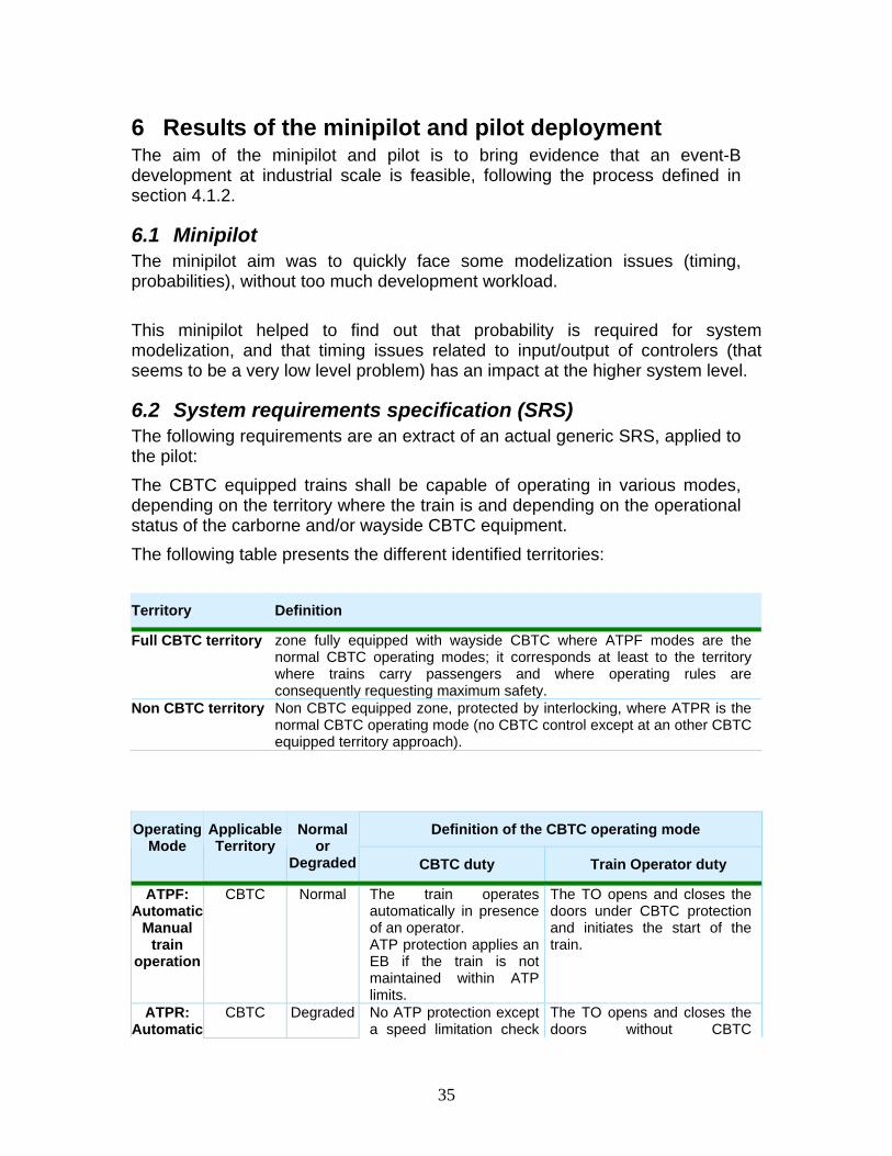
6.2 System requirements specification (SRS) The following requirements are an extract of an actual generic SRS, applied to the pilot: The CBTC equipped trains shall be capable of operating in various modes, depending on the territory where the train is and depending on the operational status of the carborne and/or wayside CBTC equipment. The following table presents the different identified territories: Territory Definition
Full CBTC territory zone fully equipped with wayside CBTC where ATPF modes are the normal CBTC operating modes; it corresponds at least to the territory where trains carry passengers and where operating rules are consequently requesting maximum safety.
Non CBTC territory Non CBTC equipped zone, protected by interlocking, where ATPR is the normal CBTC operating mode (no CBTC control except at an other CBTC equipped territory approach).
Definition of the CBTC operating mode Operating Mode
Applicable Territory
Normal or
Degraded CBTC duty Train Operator duty
ATPF: Automatic
Manual train
operation
CBTC Normal The train operates automatically in presence of an operator. ATP protection applies an EB if the train is not maintained within ATP limits.
The TO opens and closes the doors under CBTC protection and initiates the start of the train.
ATPR: Automatic
CBTC
Degraded No ATP protection except a speed limitation check
The TO opens and closes the doors without CBTC
36
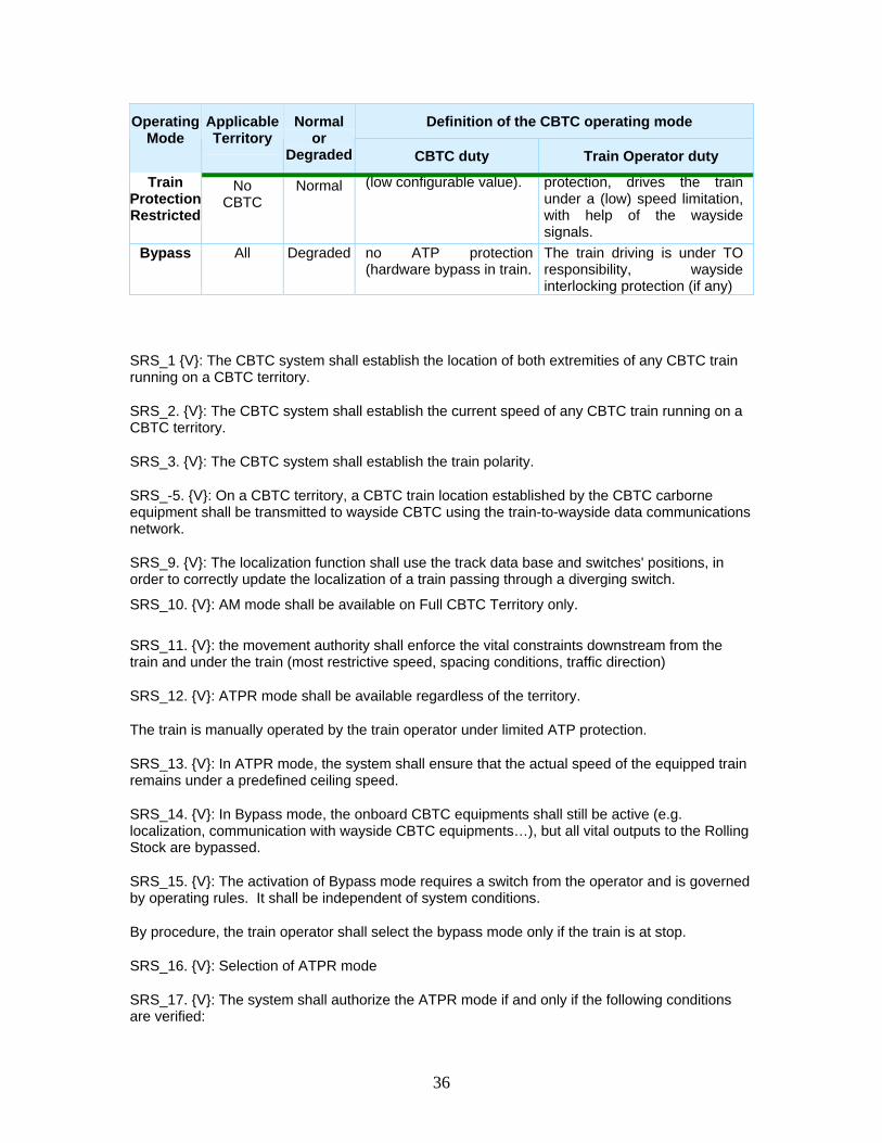
Definition of the CBTC operating mode Operating Mode
Applicable Territory
Normal or
Degraded CBTC duty Train Operator duty
Train Protection Restricted
No CBTC
Normal (low configurable value). protection, drives the train under a (low) speed limitation, with help of the wayside signals.
Bypass All Degraded no ATP protection (hardware bypass in train.
The train driving is under TO responsibility, wayside interlocking protection (if any)
SRS_1 V: The CBTC system shall establish the location of both extremities of any CBTC train running on a CBTC territory.
SRS_2. V: The CBTC system shall establish the current speed of any CBTC train running on a CBTC territory.
SRS_3. V: The CBTC system shall establish the train polarity.
SRS_-5. V: On a CBTC territory, a CBTC train location established by the CBTC carborne equipment shall be transmitted to wayside CBTC using the train-to-wayside data communications network.
SRS_9. V: The localization function shall use the track data base and switches' positions, in order to correctly update the localization of a train passing through a diverging switch.
SRS_10. V: AM mode shall be available on Full CBTC Territory only. SRS_11. V: the movement authority shall enforce the vital constraints downstream from the train and under the train (most restrictive speed, spacing conditions, traffic direction)
SRS_12. V: ATPR mode shall be available regardless of the territory.
The train is manually operated by the train operator under limited ATP protection.
SRS_13. V: In ATPR mode, the system shall ensure that the actual speed of the equipped train remains under a predefined ceiling speed.
SRS_14. V: In Bypass mode, the onboard CBTC equipments shall still be active (e.g. localization, communication with wayside CBTC equipments…), but all vital outputs to the Rolling Stock are bypassed.
SRS_15. V: The activation of Bypass mode requires a switch from the operator and is governed by operating rules. It shall be independent of system conditions.
By procedure, the train operator shall select the bypass mode only if the train is at stop.
SRS_16. V: Selection of ATPR mode
SRS_17. V: The system shall authorize the ATPR mode if and only if the following conditions are verified:
37
• the actual train speed is lower than the maximum ATPR speed
• the conditions of speed measurement are valid.
SRS_18 V : The system shall authorize the AM mode if the CBTC train is located on CBTC territory or an area designated as an approach zone leading to a CBTC territory
SRS_19. V: The CBTC system shall provide safe train separation between all trains operating on CBTC territories regardless of the operating mode.
SRS_20 V: A Movement Authority Limit (MAL) shall be determined for each reporting train according to the train travel direction and considers vital constraints (vital-MAL)
SRS_21. V: The system shall ensure that the movement authority is perodically updated and shall stop the train if the last received movement authority is too old.
SRS_22 V: In any train operating mode (except Bypass), the system shall detect rollback of the train and limit the rollback distance.
SRS_23 V: The CBTC system shall supervise each train under CBTC control, to ensure that it remains within the ATP limits, meaning that:
• train respects the safe speed
• train respects all MALs located in front of it
SRS_24 V: Emergency brakes shall be applied by the CBTC system on a CBTC equipped train in case of carborne CBTC equipment failure which prevents the CBTC system to enforce its vital functions.
SRS_25 V: For a train under CBTC control, the CBTC system shall apply emergency brake for a train if one of the following events occurs:
• overspeed is detected
• speed measurement is invalid
• train is delocalized
• train operating mode is indeterminate
• no movement authority is valid
• train length is indeterminate
• a train movement has been detected when immobilization is requested
• rollback is detected
• switch movement is detected under the train
SRS_26 V: The EB shall be released by the system if the conditions are verified:
38
• the train is at a standstill
• no EB cause is still present
• acknowledgement from train operator, if required, depending on the EB cause (according to the operator rules).
6.3 Refinement plan The above SRS contain requirements of various level of abstraction, and of various type (human behaviour, mechanical requirement, functional requirement, interface, ...). This kind of document is not suitable as an input document for event-B developers. A refinement plan has been written to classify requirements by level of abstraction, but also to complete the SRS with implicit or low-level requirements: for instance, there was no explicit requirements about avoiding collisions in the SRS, but only indirect means to avoid collisions. The complete refinement plan can be found in annex (section 9).
6.4 Example of pilot development: avoiding collision
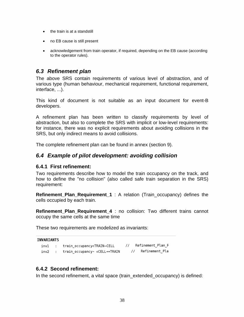
6.4.1 First refinement: Two requirements describe how to model the train occupancy on the track, and how to define the "no collision" (also called safe train separation in the SRS) requirement: Refinement_Plan_Requirement_1 : A relation (Train_occupancy) defines the cells occupied by each train. Refinement_Plan_Requirement_4 : no collision: Two different trains cannot occupy the same cells at the same time These two requirements are modelized as invariants:
6.4.2 Second refinement: In the second refinement, a vital space (train_extended_occupancy) is defined:
39
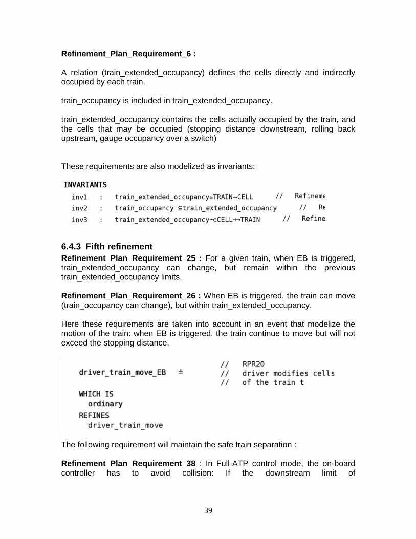
Refinement_Plan_Requirement_6 : A relation (train_extended_occupancy) defines the cells directly and indirectly occupied by each train. train_occupancy is included in train_extended_occupancy. train_extended_occupancy contains the cells actually occupied by the train, and the cells that may be occupied (stopping distance downstream, rolling back upstream, gauge occupancy over a switch) These requirements are also modelized as invariants:
6.4.3 Fifth refinement Refinement_Plan_Requirement_25 : For a given train, when EB is triggered, train_extended_occupancy can change, but remain within the previous train_extended_occupancy limits. Refinement_Plan_Requirement_26 : When EB is triggered, the train can move (train_occupancy can change), but within train_extended_occupancy. Here these requirements are taken into account in an event that modelize the motion of the train: when EB is triggered, the train continue to move but will not exceed the stopping distance.
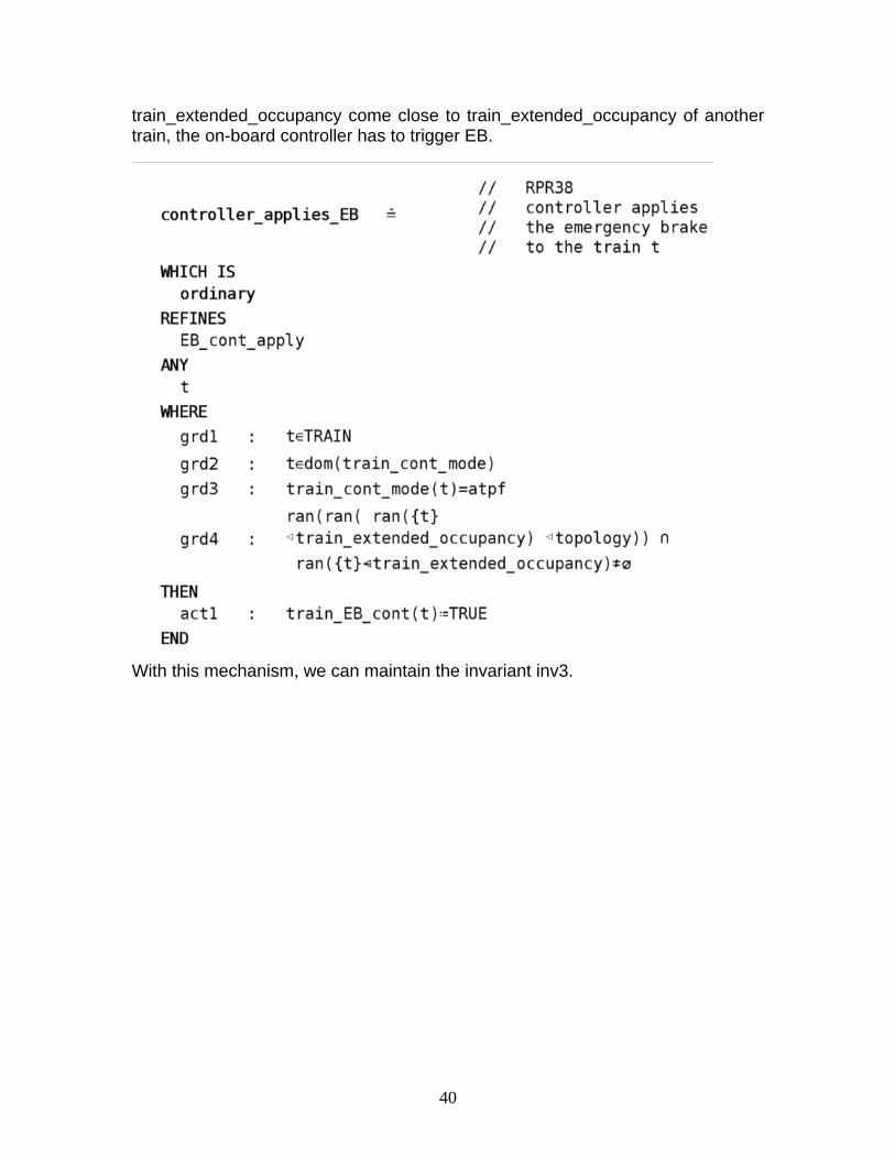
The following requirement will maintain the safe train separation : Refinement_Plan_Requirement_38 : In Full-ATP control mode, the on-board controller has to avoid collision: If the downstream limit of
40
train_extended_occupancy come close to train_extended_occupancy of another train, the on-board controller has to trigger EB.
With this mechanism, we can maintain the invariant inv3.
41
7 Lessons learnt, feedback to Methods and Tools and towards full deployment
7.1 Lessons learnt
7.1.1 Probabilities and failures It appeared quite quickly that proving safety (or availability) properties without any failure is pointless, since in that case we can only prove that the system is safe...providing nothing wrong happens! It is therefore needed to model failures. But then, some proof obligations (safety properties after a failure) cannot be discharged any more. To prove these properties, it appeared that probabilities had to be added in the model. An experiment has been performed on the minipilot to add probabilities, with success.
7.1.2 Requirements The specifications (especially the SRS) are basically lists of requirements, but only few of them are properties, and moreover, the main properties are implicit. For instance, in the actual SRS, there was no requirement about avoiding collision. But there were a lot of requirements on means to avoid collision, like stopping before a red signal. This implies an abstraction work when the refinement plan is written; it is not only a abstraction classification of existing requirement.
7.1.3 Temporal constraints In the minipilot, we focused on the temporal constraints, and managed to prove some temporal properties, but had to prove many proof obligations. That was because all requirements were modelized (on purpose) as properties. In the pilot, we decided to modelize some requirements as guards or actions, and prove only the actual safety properties (no collision, no derailment).
7.2 Feedback to Methods and Tools
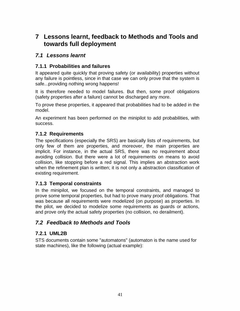
7.2.1 UML2B STS documents contain some "automatons" (automaton is the name used for state machines), like the following (actual example):
42
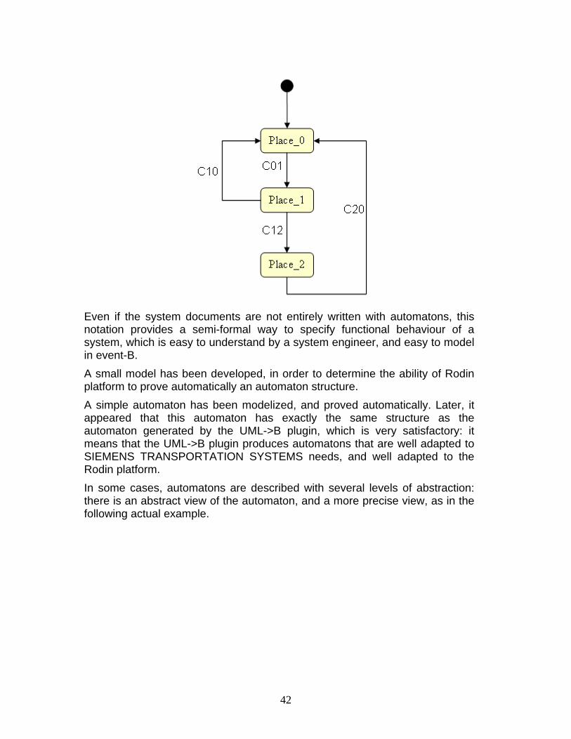
Even if the system documents are not entirely written with automatons, this notation provides a semi-formal way to specify functional behaviour of a system, which is easy to understand by a system engineer, and easy to model in event-B. A small model has been developed, in order to determine the ability of Rodin platform to prove automatically an automaton structure. A simple automaton has been modelized, and proved automatically. Later, it appeared that this automaton has exactly the same structure as the automaton generated by the UML->B plugin, which is very satisfactory: it means that the UML->B plugin produces automatons that are well adapted to SIEMENS TRANSPORTATION SYSTEMS needs, and well adapted to the Rodin platform. In some cases, automatons are described with several levels of abstraction: there is an abstract view of the automaton, and a more precise view, as in the following actual example.
43
In this example, the abstract automaton (top left) has three states. Then, each of these three states is "refined" to add more details. The refinement of automatons is supported by the UML2B tool.
44
7.2.2 proB The plugin proB has been used on a case study (San Juan metro system) provided by Siemens Transportation Systems. The result of the study described in 5.5 shows that proB is capable of dealing with large scale industrial models and is more efficient than AtelierB for dealing with large data sets and complex properties. About a man month of effort has been replaced by 17 minutes of computation. Furthermore, proB provides help in finding the faulty data when a property is not fulfilled. We believe we have established that the latest version of proB can therefore be used for debugging large industrial models. In order to overcome the challenges of this case study, various extensions had to be developed: a new parser, an integrated type checker, a new data structure for large sets and relations, and an improved constraint propagation algorithm. In the future, Siemens Transportation Systems plan to replace Atelier B by proB for this specific use (data proof regarding formal properties). STS and the University of Düsseldorf will validate proB in order to use it within the SIL4 development cycle at STS. We also plan to attack even bigger specifications such as the model of the Canarsie line (the complete B model of which contains 273,000 lines of B, up from 100,000 lines for Meteor).
7.3 Towards full deployment The minipilot and the pilot were prototypes of event-B development, enabling to define an industrial development process, evaluate and improve the event-B related tools, and gain experience in event-B development. The next step is a full deployment, i.e. a large scale development of a CBTC function, from the system level to the software level, including event-B model decomposition, event-B model generation, event-B to B translation.
7.4 event-B model decomposition With the composition plug-in developed by University of Southampton, the system event-B model will be decomposed into several equipments, with communications between equipments.
7.4.1 event-B model generation A systematic way of writing the model will be pursued, in order to specify automatic generation of formal model from graphic automatons. The formal models will be validated against the system specification document, with the support of animation tools to be developed in the DEPLOY project.

45
7.4.2 event-B to B translation The RODIN2B tool will be used to generate classical B (supported by atelier B). The objective is to generate B models that are close to the B model currently developed at STS.
46
8 Conclusion STS has now a long experience with B development at software level. But the minipilot and the pilot development raised new technical issues that were not addressed during the past experience: in particular, the modelization of failures is something new, requiring new techniques (use of probability linked with the event-B model). The minipilot and the pilot resulted in an industrial process that will be followed in the future event-B developments at Siemens Transportation Systems. One unexpected result is the proB tool, which will soon be used at software level in Siemens Transportation Systems.
47
9 ANNEX : refinement plan
9.1 First refinement: Refinement_Plan_Requirement_1 : A relation (Train_occupancy) defines the cells occupied by each train. Refinement_Plan_Requirement_2 : A train may Appear/dissapear from Train_occupancy only if the train is located on the garage zone. Refinement_Plan_Requirement_3 : A train can change its location (by modifying Train_occupancy). Refinement_Plan_Requirement_4 : no collision: Two different trains cannot occupy the same cells at the same time.
9.2 Second refinement : Refinement_Plan_Requirement_6 : A relation (Train_extended_occupancy) defines the cells directly and indirectly occupied by each train. Train_occupancy is included in Train_extended_occupancy. Train_extended_occupancy contain the cells actually occupied by the train, and the cells that may be occupied (stopping distance downstream, rolling back upstream, gauge occupancy over a switch) Refinement_Plan_Requirement_7 : A relation (Topology) associates to each cell the cells immediately nearby . This relation is not a constant (the switch modify this relation). This relation is oriented and depends of the direction (up/down) of the track. For a given direction, a cell can have one or zero nextby cell (zero for end of track, or in the case of a switch in intermediate position). Refinement_Plan_Requirement_8 : For each cell X, if Y is the nearby cell in down direction, Then X is the nearby cell of Y in the up direction. For each cell X, if Y is the nearby cell in up direction, Then X is the nearby cell of Y in the down direction. Refinement_Plan_Requirement_9 : The train front occupy one cell, the train rear occupy another cell. These two cells define a motion direction for the train. Refinement_Plan_Requirement_10 : A train can change its location (modifying Train_ extended_occupancy).
48
Refinement_Plan_Requirement_11 : no collision : Two different trains cannot occupy (with Train_extended_occupancy) the same cells at the same time. Refinement_Plan_Requirement_12 : A train has a speed (positive or negative). Refinement_Plan_Requirement_13 : Train_extended_occupancy contain :
• Train_occupancy • Rolling back margin (rear of the train + N cells upstream). • Stopping distance (depends of speed) • Gauge occupancy (A constant relation gives, for each cell, the cells (if
any) indirectly occupied).
9.3 Third refinement: Refinement_Plan_Requirement_14 : The on-board controller of each train sends its id number, its speed and its position (position of the rear and position of the front) to the wayside controller. The wayside controller send to each train a permit to go forward until a MAL (movement authorization limit). There is no common cell between the authorized area (area from the front of the train to the MAL) and Train_extended_occupancy of any other train. Refinement_Plan_Requirement_15 : If a train is authorized to move (its MAL is downstream the front of the train), the train can modify its speed and train_extended_occupancy. Train_extended_occupancy must not exceed the MAL, otherwise cont_EB (controler output that triggers the train Emergency Brake) shall be triggered. Refinement_Plan_Requirement_16 : Each train has several control modes:
• Full ATP (ATP = Automatic Train Protection)
• ATPR (ATPR = Automatic Train Protection Restricted)
• Bypass (CBTC is bypassed) Refinement_Plan_Requirement_17 : Each train has several driving modes : bypass, ATPR, Full-ATP. Refinement_Plan_Requirement_57 : Topology can be modified by a switch, providing that the switch is authorized to move, and there is no train occupying (with train_extended_occupancy) the switch. Refinement_Plan_Requirement_58 : the wayside controller defines the switch authorized to move.
49
Refinement_Plan_Requirement_18 : In bypass control mode, the controller has to trigger the cont_EB. Refinement_Plan_Requirement_19 : When bypass driving mode is selected, the controller has to and switch to bypass control mode. Refinement_Plan_Requirement_23 : The controller can change the control mode. Refinement_Plan_Requirement_24 : The driver can change the driving mode.
9.4 fourth refinement Refinement_Plan_Requirement_20 : In ATPR and bypass driving mode, the driver has to avoid collision. Refinement_Plan_Requirement_21 : In ATPR control mode, the carborne controller has limit the speed to 25km/h. If the speed of the train is higher than 25km/h, the carborne controller shall trigger cont_EB. Refinement_Plan_Requirement_22 : In Full-ATP control mode, the carborne controller has to avoid collision.
9.5 fith refinement Refinement_Plan_Requirement_25 : For a given train, when EB is triggered, train_extended_occupancy can change, but remain within the previous train_extended_occupancy limits. Refinement_Plan_Requirement_26 : When EB is triggered, The train can move (train_occupancy can change), but within train_extended_occupancy. Refinement_Plan_Requirement_27 : When EB is triggered, the speed decreases. Refinement_Plan_Requirement_28 : The full ATP control mode is available only on CBTC territory. When the controller doesn’t know the position of the train on the line, the ATP control mode is not authorized, even if the actual position of the train is on the CBTC territory. A train already in ATP control mode shall not enter (with train_extended_occupancy) a non-CBTC territory,
50
and the carborne controller shall trigger EB when train_extended_occupancy of a train in full ATP control mode is close to a non-CBTC territory. Refinement_Plan_Requirement_29 : ATPR control mode is authorized anywhere, anytime. ATPR provides a restricted protection (train speed is limited to 25km/h), the train is under driver’s responsibility (no protection against collision). Refinement_Plan_Requirement_30 : Bypass control mode is authorized anywhere, anytime. When bypass is selected, the outputs of the CBTC are bypassed, but the controller triggers the EB output, just to be on the safe side. In bypass mode, the train is under driver’s full responsibility (no protection against collision nor overspeed). Refinement_Plan_Requirement_31 : The driver can select any driving mode, anywhere, anytime. The controller shall protect the train (EB triggered, no control mode change) if the driver endangers the train by selecting a wrong driving mode. Refinement_Plan_Requirement_32 : Bypass mode selected on the driving console switch shall result in a trigered EB. Refinement_Plan_Requirement_33 : In case of Full ATP mode selected on the driving console switch while the train is on a non CBTC territory, the control mode shall remain in the previous mode. Refinement_Plan_Requirement_34 : Any discrepancies between selected mode and control mode shall result in a triggered EB. Refinement_Plan_Requirement_35 : As a consequence of the two previous properties: Full ATP mode selection on the driving console switch while the train is on a non CBTC territory shall result in a trigered EB. Refinement_Plan_Requirement_36 : The initialization control mode is ATPR. Refinement_Plan_Requirement_37 : The driving console switch is vital: the controller sees the actual selected driving mode. Refinement_Plan_Requirement_38 : In Full-ATP control mode, the carborne controller has to avoid collision: If the downstream limit of train_extended_occupancy come close to train_extended_occupancy of another train, the carborne controller has to trigger EB.
9.6 6th refinement : Refinement_Plan_Requirement_39 : In Full-ATP control mode, the carborne controller has to trigger the EB in case of rollback (negative speed) Refinement_Plan_Requirement_40 : In ATPR and bypass driving mode, the driver has to trigger the EB in case of rollback (negative speed).
51
Refinement_Plan_Requirement_41 : the maximum speed of the train is 100km/h Refinement_Plan_Requirement_42 : each cell is associated with a speed limit (between 0 to 100km/h). Refinement_Plan_Requirement_43 : in order to avoid derailment, the speed of the train has to respect the lowest speed limit of the cells that are occupied by the train, or trigger the EB. In ATPR and bypass driving mode, the driver is responsible for the speed of the train. In ATPF control mode, the controller has to trigger cont_EB in case of overspeed. Refinement_Plan_Requirement_44 : the wayside controller can change the speed limit of any part of the line, and send this information to Full-ATP trains. Refinement_Plan_Requirement_45 : In Full-ATP control mode, the carborne controller has to trigger the EB in case of overspeed. Refinement_Plan_Requirement_46 : each cell of the CBTC territory is associated with one authorized direction (or no authorized direction). Refinement_Plan_Requirement_47: the wayside controller can change the authorized direction of any part of the line, and send this information to Full-ATP trains. Refinement_Plan_Requirement_48 : . In ATPR and bypass driving_mode, the driver has to follow the authorized direction, and has to trigger the EB if the train occupy (with train_extended_occupancy)a cell with an authorized direction different of the direction of the train (or if one cell has no authorized direction). Refinement_Plan_Requirement_49 : : In Full-ATP control mode, the carborne controller has to trigger the EB if the train occupy a cell with an authorized direction different of the direction of the train (or if one cell has no authorized direction). Refinement_Plan_Requirement_50 : When the driver/controller accelerate, the speed increases, and the train_extended_occupancy is extended downstream. Refinement_Plan_Requirement_51 : When the driver/controller brakes, the speed decreases, and the train_extended_occupancy is reduced downstream. Train_occupancy must still remain within train_extended_occupancy. Refinement_Plan_Requirement_52 : When the train moves, a cell is added downstream train_occupancy and train_extended_occupancy, and the last
52
(upstream) cell is removed from train_occupancy and train_extended_occupancy.
9.7 7th refinement : Refinement_Plan_Requirement_53 : the CBTC_territory is divided into sections. There is no intersection between sections. The union of all sections is the complete CBTC_territory. For each section, all cells of that section have the same authorized direction. Each cell of a section has to neighbors, except the two ends of the section. Refinement_Plan_Requirement_54 : on both ends of each section, a signal (green or red) authorize (or not) a train to enter a section with the wrong direction. For the down(resp up) end of a section, the signal is located on the cell close to the down(resp up) end of a section, in the down(resp up) direction. This signal is associated with the up (resp down) direction. Train moving in the up (resp down) direction have to obey the signal before entering on the section. The signals status (green or red) are set by the wayside controller, accordingly with the section directions. Refinement_Plan_Requirement_55 : the driver has to stop before a red signal. Refinement_Plan_Requirement_56 : in bypass and ATPR driving mode, the driver activates a speed lever to accelerate/neutral/decelerate. The train gets the position of the speed lever (accelerate/neutral/decelerate). Refinement_Plan_Requirement_59 : in ATPF control mode, the controller send an accelerate/neutral/decelerate order to the train. Refinement_Plan_Requirement_60 : a switch involves tree cells : the point_cell, the direct_cell and the deviate_cell. For a given switch, topology can link these cells with the following cases : point_cell |->direct_cell (and reverse), point_cell |->deviate_cell (and reverse), or no image for point cell (switch in intermediate position). Refinement_Plan_Requirement_61 : There is no switch included within a section : a section contain zero or one cell of a switch (point, direct, deviate). The switch cell is located at one end of the section. Refinement_Plan_Requirement_62 : each switch cell is associated with a signal to protect the switch
53
Refinement_Plan_Requirement_78 : Cont_train_speed is initialized at the maximum train speed of the train. Cont_train_speed => train_speed, or EB_cont_harware=true. Refinement_Plan_Requirement_81 : Cont_train_occupancy is initialized at train_occupancy Cont_train_extended _occupancy is initialized at train_extended _occupancy Cont_train_occupancy includes train_occupancy Cont_train_extended_occupancy includes train_extended_occupancy Cont_train_extended_occupancy includes Cont_train_occupancy
9.8 Decomposition The system is divided into sub-systems :
• carbornecontroller and its variable/events, • Driver and its variable/events, • Train and its variable/events, • Wayside controller and its variable/events • Track and its variable/events • Time (universal time for all sub-systems)
The wayside controller is then decomposed into several zone controller (each one dealing with a part of the CBTC territory). Each ZC (Zone Controller) can communicate with the trains that are on the ZC area. A ZC can communicate with the nearby ZC.
9.8.1 Time Refinement_Plan_Requirement_77: Time starts at zero, and is increasing.
9.8.2 Driver Refinement_Plan_Requirement_63: The driver has access to the following information : (non exhaustive) Position of the driving switch aspect of the signals train_extended_occupancy Refinement_Plan_Requirement_64: The driver can modify the following state variables : (non exhaustive) Position of the speed lever (accelerate/neutral/decelerate). EB button (EB_requested/EB_not_requested) Position of the driving switch Applicable Refinement_Plan_Requirement :20,24,40,48, (non exhaustive)
54
9.8.3 train Applicable Refinement_Plan_Requirement : 3,10,12,13,25,26,27,41(non exhaustive) Refinement_Plan_Requirement_65 : The train has access to the following information : (non exhaustive) Position of the speed lever (accelerate/neutral/decelerate). accelerate/neutral/decelerate order from the controller (in ATPF control_mode) EB button (EB_requested/EB_not_requested) Cont_EB_harware Time Refinement_Plan_Requirement_66: The train can modify the following state variables : (non exhaustive) Train_speed Train_occupancy Train_extended_occupancy Refinement_Plan_Requirement_76: Train speed increase is limited, it can increase only by max_speed_increment every CC_cycle_time. Refinement_Plan_Requirement_80: Train_occupancy and Train_extended_occupancy evolution is limited : one cell only can be added/removed at both ends every CC_cycle_time.
9.8.4 Carborne controler (CC) Applicable Refinement_Plan_Requirement : 14,18,21,22,23,28,34,35,36,37,38,39,45,59(non exhaustive) Refinement_Plan_Requirement_67: The CC has access to the following state variables : (non exhaustive) Position of the driving switch Train_speed Train_occupancy Train_extended_occupancy permit to go forward until a MAL (movement authorization limit). Time Refinement_Plan_Requirement_68: The CC can modify the following state variables : (non exhaustive) Cont_train_speed Cont_train_occupancy Cont_train_extended_occupancy
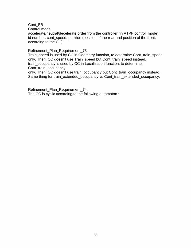
55
Cont_EB Control mode accelerate/neutral/decelerate order from the controller (in ATPF control_mode) id number, cont_speed, position (position of the rear and position of the front, according to the CC) Refinement_Plan_Requirement_73: Train_speed is used by CC in Odometry function, to determine Cont_train_speed only. Then, CC doesn't use Train_speed but Cont_train_speed instead. train_occupancy is used by CC in Localization function, to determine Cont_train_occupancy only. Then, CC doesn't use train_occupancy but Cont_train_occupancy instead. Same thing for train_extended_occupancy vs Cont_train_extended_occupancy. Refinement_Plan_Requirement_74: The CC is cyclic according to the following automaton :
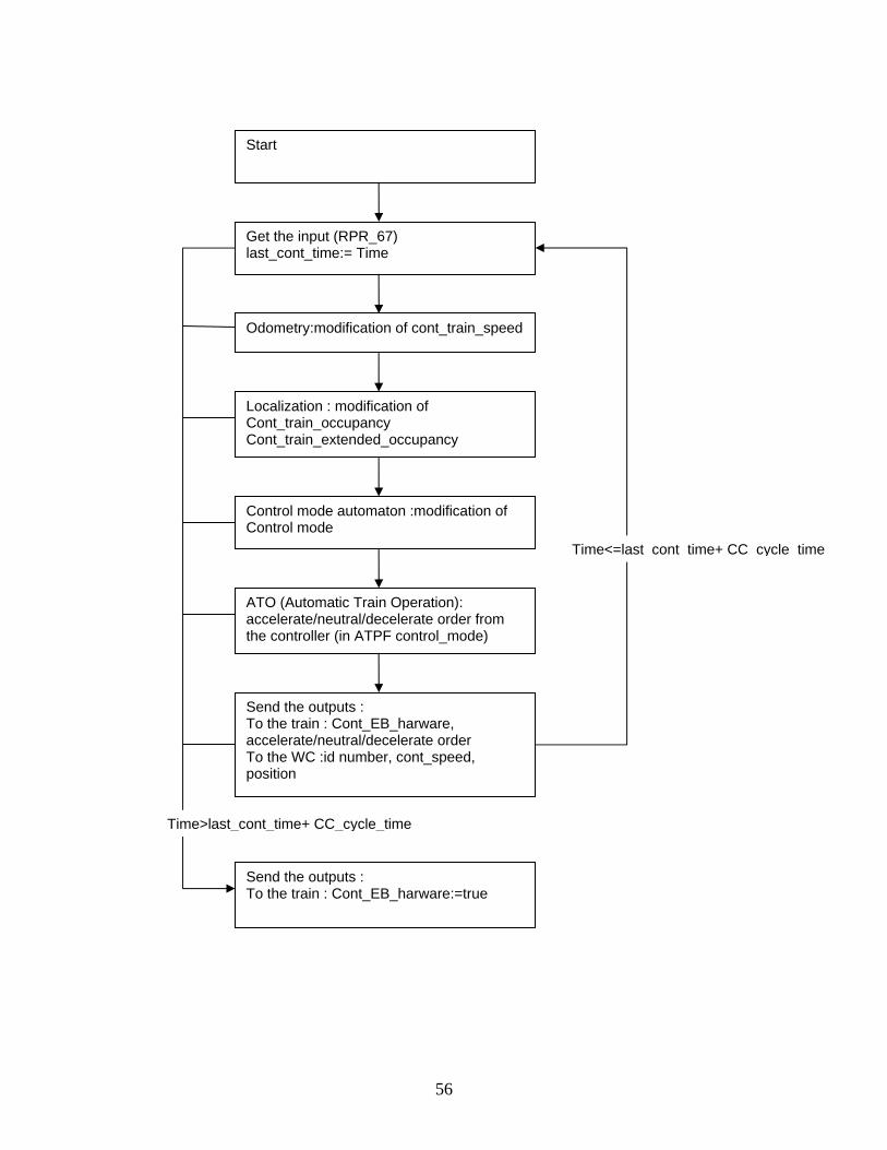
56
Get the input (RPR_67) last_cont_time:= Time
Odometry:modification of cont_train_speed
Localization : modification of Cont_train_occupancy Cont_train_extended_occupancy
Control mode automaton :modification of Control mode
ATO (Automatic Train Operation): accelerate/neutral/decelerate order from the controller (in ATPF control_mode)
Send the outputs : To the train : Cont_EB_harware, accelerate/neutral/decelerate order To the WC :id number, cont_speed, position
Start
Send the outputs : To the train : Cont_EB_harware:=true
Time<=last_cont_time+ CC_cycle_time
Time>last_cont_time+ CC_cycle_time
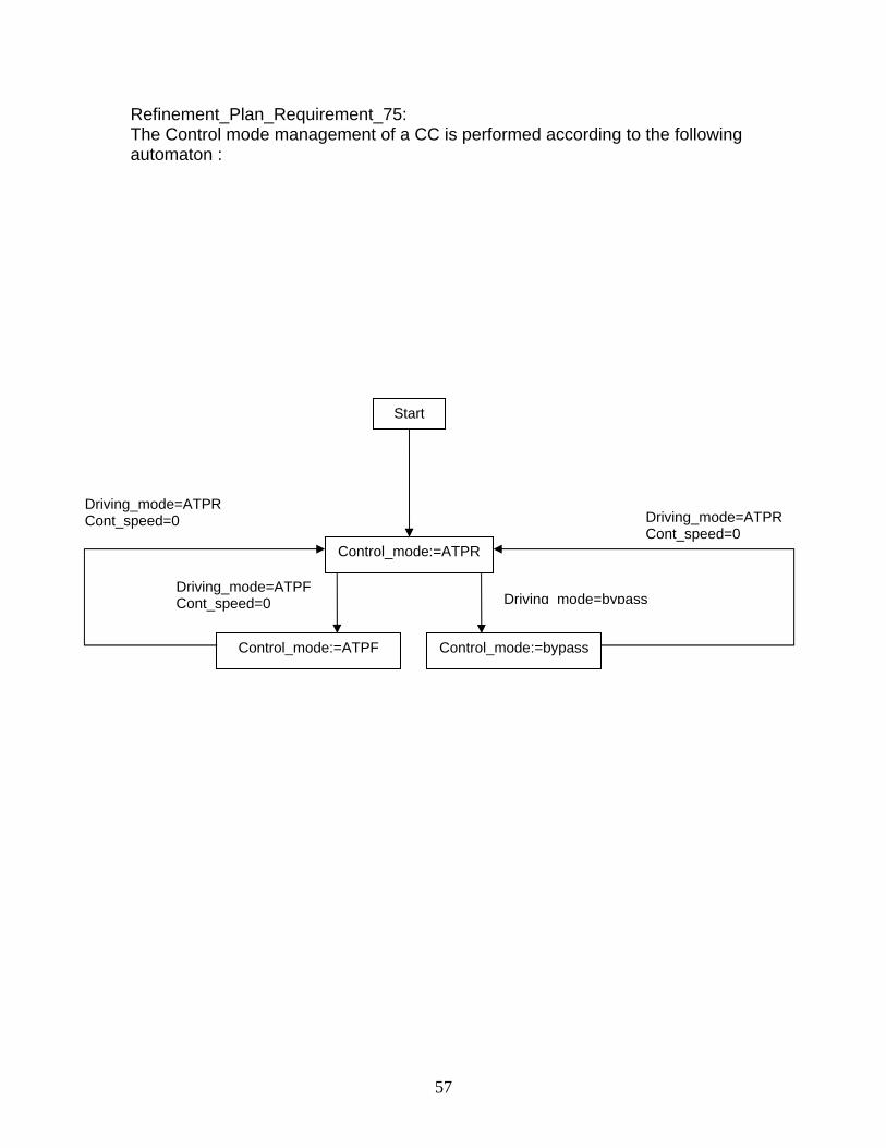
57
Refinement_Plan_Requirement_75: The Control mode management of a CC is performed according to the following automaton :
Control_mode:=bypass
Start
Driving mode=bypass
Control_mode:=ATPF
Driving_mode=ATPF Cont_speed=0
Control_mode:=ATPR
Driving_mode=ATPR Cont_speed=0
Driving_mode=ATPR Cont_speed=0
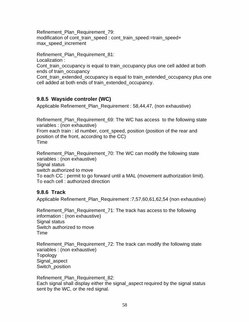
58
Refinement_Plan_Requirement_79: modification of cont_train_speed : cont_train_speed:=train_speed+ max_speed_increment Refinement_Plan_Requirement_81: Localization : Cont_train_occupancy is equal to train_occupancy plus one cell added at both ends of train_occupancy Cont_train_extended_occupancy is equal to train_extended_occupancy plus one cell added at both ends of train_extended_occupancy.
9.8.5 Wayside controler (WC) Applicable Refinement_Plan_Requirement : 58,44,47, (non exhaustive) Refinement_Plan_Requirement_69: The WC has access to the following state variables : (non exhaustive) From each train : id number, cont_speed, position (position of the rear and position of the front, according to the CC) Time Refinement_Plan_Requirement_70: The WC can modify the following state variables : (non exhaustive) Signal status switch authorized to move To each CC : permit to go forward until a MAL (movement authorization limit). To each cell : authorized direction
9.8.6 Track Applicable Refinement_Plan_Requirement :7,57,60,61,62,54 (non exhaustive) Refinement_Plan_Requirement_71: The track has access to the following information : (non exhaustive) Signal status Switch authorized to move Time Refinement_Plan_Requirement_72: The track can modify the following state variables : (non exhaustive) Topology Signal_aspect Switch_position Refinement_Plan_Requirement_82: Each signal shall display either the signal_aspect required by the signal status sent by the WC, or the red signal.


![7748655w[1] Installation D5~D16](https://img.pdfslide.us/doc/110x75/577ccd1c1a28ab9e788b85d7/7748655w1-installation-d5d16.jpg)