Embed Size (px)
Citation preview
GR
© KROHNE 11/2003 7.30926.31.00
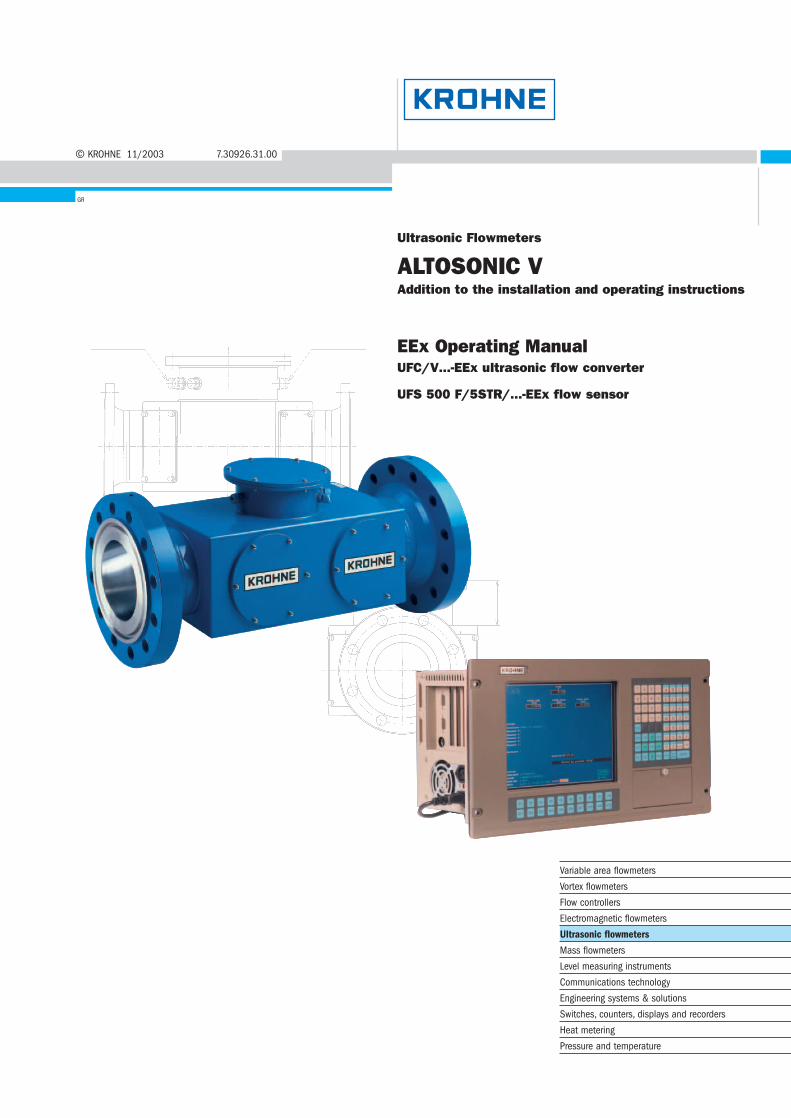
Ultrasonic Flowmeters
ALTOSONIC VAddition to the installation and operating instructions
EEx Operating ManualUFC/V...-EEx ultrasonic flow converter
UFS 500 F/5STR/...-EEx flow sensor
Variable area flowmeters
Vortex flowmeters
Flow controllers
Electromagnetic flowmeters
Ultrasonic flowmeters
Mass flowmeters
Level measuring instruments
Communications technology
Engineering systems & solutions
Switches, counters, displays and recorders
Heat metering
Pressure and temperature
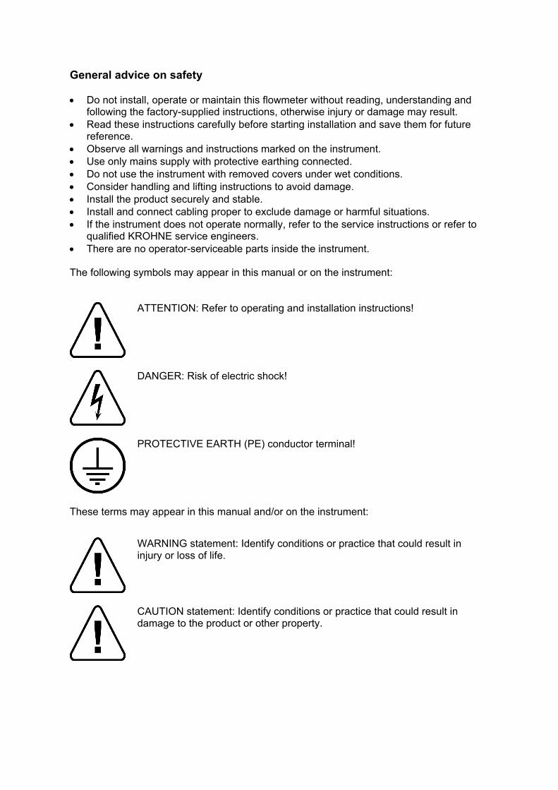
General advice on safety • Do not install, operate or maintain this flowmeter without reading, understanding and
following the factory-supplied instructions, otherwise injury or damage may result. • Read these instructions carefully before starting installation and save them for future
reference. • Observe all warnings and instructions marked on the instrument. • Use only mains supply with protective earthing connected. • Do not use the instrument with removed covers under wet conditions. • Consider handling and lifting instructions to avoid damage. • Install the product securely and stable. • Install and connect cabling proper to exclude damage or harmful situations. • If the instrument does not operate normally, refer to the service instructions or refer to
qualified KROHNE service engineers. • There are no operator-serviceable parts inside the instrument. The following symbols may appear in this manual or on the instrument:
ATTENTION: Refer to operating and installation instructions!
DANGER: Risk of electric shock!
PROTECTIVE EARTH (PE) conductor terminal!
These terms may appear in this manual and/or on the instrument:
WARNING statement: Identify conditions or practice that could result in injury or loss of life.
CAUTION statement: Identify conditions or practice that could result in damage to the product or other property.
Disclaimer • This document contains important information on the instrument. KROHNE attempts to
be as accurate and up-to-date as possible but assumes no responsibility for errors or omissions. Nor does KROHNE make any commitment to update the information contained herein. This manual and all other documents are subject to change without prior notice.
• KROHNE will not be liable for any damage of any kind by using its instrument, including, but not limited to direct, indirect, incidental, punitive and consequential damages.
• This disclaimer does not apply in case KROHNE has acted on purpose or with gross negligence. In the event any applicable law does not allow such limitations on implied warranties or the exclusion of limitation of certain damages, you may, if such law applies to you, not be subject to some or all of the above disclaimer, exclusions or limitations.
• Any instrument purchased from KROHNE is warranted in accordance with the relevant product documentation and our Terms and Conditions of Sale.
• KROHNE reserves the right to alter the content of its documents, including this disclaimer in any way, at any time, for any reason, without prior notification, and will not be liable in any way for possible consequences of such changes.
Product liability and warranty • Responsibility for suitability and intended use of this ultrasonic flowmeter rests solely
with the user. Improper installation and operation of the flowmeter (system) may lead to loss of warranty.
• In addition, the Terms and Conditions of Sale are applicable and are the basis for the purchase contract.
• If flowmeters need to be returned to KROHNE, please note the information given on the last pages of the installation and operating instructions. KROHNE regrets that they cannot repair or check flowmeter(s) unless accompanied by the completed form (see last pages of the installation and operating instructions).
Items included with order • UFC-V/EEx (standard or with optional 30 W heater) or UFC-V/LT-EEx (low-
temperature) Ultrasonic Flow Converter • UFS 500 F/5STR-EEx ultrasonic flow tube, in the size as indicated on the packaging
box. • Signal cable Documentation These instructions are an extension to the installation instructions and apply to ALTOSONIC V UFC-V/EEx and UFC-V/LT-EEx Ultrasonic Flow Converters and the UFS 500 F/5STR-EEx Flow Sensor. All technical information as described in the installation instructions is applicable, when not specifically excluded, completed or replaced by the instructions in these additional instructions.

This instrument is developed and manufactured by: KROHNE Altometer Kerkeplaat 12 3313 LC Dordrecht The Netherlands For information, maintenance or service please contact your nearest local KROHNE representative.
WARNING !
No changes may be made to the devices. Unauthorized changes might affect the explosion safety of the devices.
Be sure to follow these instructions!
IMPORTANT !
• The prescriptions and regulations as well as the electrical data described in the EC type examination certificate must be obeyed.
• Beside the instructions for electrical installations in non-hazardous locations according to the applicable national standard (equivalent of HD 384 or IEC 364, e.g. VDE 0100), especially the regulations in EN 60079-14 "Electrical installations in hazardous locations" or equivalent national standard (e.g. DIN VDE 0165 Part 1) must be strictly followed.
• Installation, establishment, utilization and maintenance are only allowed to be executed by personnel with an education in explosion safety!
Table of Contents 1. System components..........................................................................2 1.1 General information .................................................................................... 2 1.2 Flow Sensor ................................................................................................ 2 1.3 Flow Converter............................................................................................ 2 1.3.1 Versions...................................................................................................................................... 2 1.3.2 Cable and conduit entries........................................................................................................... 3 1.3.3 Warning messages..................................................................................................................... 3 1.3.4 Heating element and thermostats .............................................................................................. 3 2. Electrical connections .......................................................................5 2.1 Equipotential bonding system ..................................................................... 6 2.2 Connecting cables ...................................................................................... 6 2.3 Connection diagram.................................................................................... 7 3. Service and maintenance..................................................................8 3.1 Introduction ................................................................................................. 8 3.2 Replacement of electronics unit .................................................................. 9 3.3 Replacement of power fuse(s) .................................................................. 10 3.3.1 AC versions 115/230 V AC and 100/200 V AC ........................................................................ 10 3.3.2 24 V AC/DC version ................................................................................................................. 11 3.4 Changing power supply voltage (not for 24 V AC/DC version).................. 11 Appendix 1 Type Examination Certificate ..............................................12 Appendix 2 Declaration of Conformity....................................................22 Appendix 2 Declaration of Conformity....................................................22 Appendix 3 Data plates ..........................................................................23
ALTOSONIC V 2
1. System components
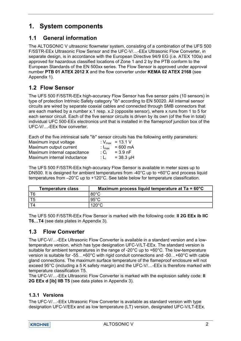
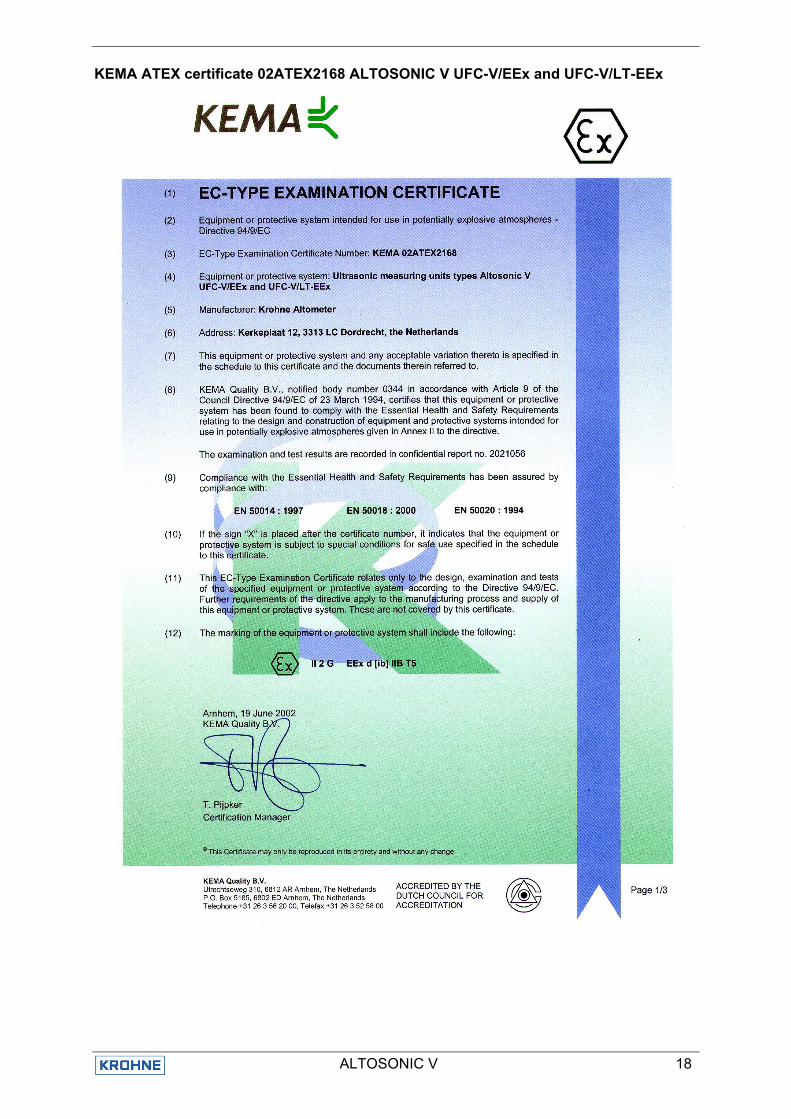
1.1 General information The ALTOSONIC V ultrasonic flowmeter system, consisting of a combination of the UFS 500 F/5STR-EEx Ultrasonic Flow Sensor and the UFC-V/…-EEx Ultrasonic Flow Converter, in separate design, is in accordance with the European Directive 94/9 EG (i.e. ATEX 100a) and approved for hazardous classified locations of Zone 1 and 2 by the PTB conform to the European Standards of the EN 500xx series. The Flow Sensor is approved under approval number PTB 01 ATEX 2012 X and the flow converter under KEMA 02 ATEX 2168 (see Appendix 1).
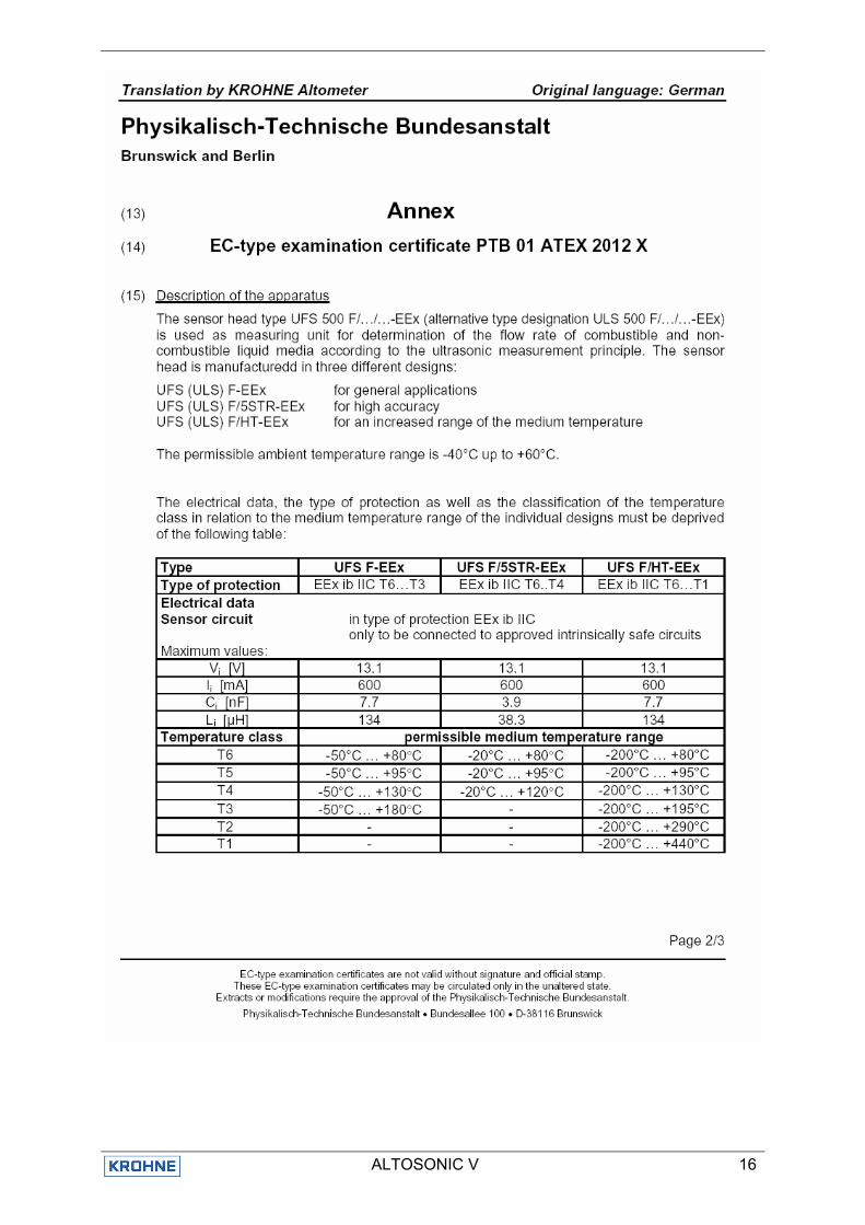
1.2 Flow Sensor The UFS 500 F/5STR-EEx high-accuracy Flow Sensor has five sensor pairs (10 sensors) in type of protection Intrinsic Safety category "ib" according to EN 50020. All internal sensor circuits are wired by separate coaxial cables and connected through SMB connectors that are each marked by a number x.1 resp. x.2 (opposite sensor), where x runs from 1 to 5 for each sensor circuit. Each of the five sensor circuits is driven by its own (of the five in total) individual UFC 500-EEx electronics unit that is installed in the flameproof junction box of the UFC-V/…-EEx flow converter. Each of the five intrinsical safe "ib" sensor circuits has the following entity parameters: Maximum input voltage : Vmax = 13.1 V Maximum output current : Imax = 600 mA Maximum internal capacitance : Ci = 3.9 nF Maximum internal inductance : Li = 38.3 µH The UFS 500 F/5STR-EEx high-accuracy Flow Sensor is available in meter sizes up to DN500. It is designed for ambient temperatures from -40°C up to +60°C and process liquid temperatures from –20°C up to +120°C. See table below for temperature classification.
Temperature class Maximum process liquid temperature at Ta = 60°C T6 80°C T5 95°C T4 120°C
The UFS 500 F/5STR-EEx Flow Sensor is marked with the following code: II 2G EEx ib IIC T6…T4 (see data plates in Appendix 3).
1.3 Flow Converter The UFC-V/…-EEx Ultrasonic Flow Converter is available in a standard version and a low-temperature version, which has type designation UFC-V/LT-EEx. The standard version is suitable for ambient temperatures in the range of -20°C up to +60°C. The low-temperature version is suitable for -55…+60°C with rigid conduit connections and -50…+60°C with cable gland connections. The maximum surface temperature of the flameproof enclosure will not exceed 95°C (including a 5 K safety margin) and the UFC-V/…-EEx is therefore marked with temperature classification T5. The UFC-V/…-EEx Ultrasonic Flow Converter is marked with the explosion safety code: II 2G EEx d [ib] IIB T5 (see data plates in Appendix 3).
1.3.1 Versions The UFC-V/…-EEx Ultrasonic Flow Converter is available as standard version with type designation UFC-V/EEx and as low temperature (LT) version, designated UFC-V/LT-EEx.
ALTOSONIC V 3
Both consist of an approved flameproof box, in which five UFC 500…-EEx electronics units and the connecting terminals are installed. The low-temperature version is additionally provided with a heating element of maximum 200 W power, which is controlled by a thermostat to keep the temperature inside the flameproof box above -20°C. The standard (-20°C) version can optionally be provided with a heating element of maximum 30 W and thermostat, to prevent condensation inside the flameproof box. The UFC 500…-EEx electronics unit can be equipped with one of the following linear power supplies: • 115/230 Vac ±13%, 48 – 63 Hz, 12 VA • 100/200 Vac -15%/+10%, 48 – 63 Hz, 12 VA • 24/48 Vac ±13%, 48 – 63 Hz, 12 VA Or with the switching mode power supply of 24 Vac/dc -25%/+33%, 8 W. All five UFC 500…-EEx electronics units must have the same power supply version. Each unit is also provided with a RS 485 communication module. Each UFC 500…-EEx electronics unit drives two of the four intrinsically safe "ib" ultrasonic sensor circuits that form one measuring line (i.e. two opposite ultrasonic transducers) of the UFS 500 F/5STR-EEx Flow Sensor. The intrinsically safe output circuits each has the following maximum values (i.e. entity parameters): • Maximum output voltage : Vo = 8.7 V • Maximum output current : Io = 360 mA • Maximum allowed external capacitance : Co = 1.2 µF • Maximum allowed external inductance : Lo = 0.17 mH
1.3.2 Cable and conduit entries The connecting cables for power supply of the five UFC 500…-EEx electronics units, the heating element with thermostat (only applies to LT-version) and the RS 485 communication module either run through ATEX-approved flameproof "EEx d" cable glands or rigid metal conduits. The rigid conduits must be sealed by ATEX-approved flameproof sealing devices (i.e. stopping boxes) directly at the entrances of the flameproof box. All non-used openings must be sealed by ATEX-approved flameproof blind plugs.
1.3.3 Warning messages The stainless steel data plate of all UFC-V/…-EEx versions is permanently attached to the cover of the flameproof approved box by four stainless steel rivets and contains following warning messages (see Appendix 3): • DO NOT OPEN "EEx d" ENCLOSURE WHILE ENERGIZED. WAIT AT LEAST 30
MINUTES AFTER DE-ENERGIZING. • ONLY CABLE GLANDS OF "EEx d" APPROVED TYPE IN ACCORDANCE WITH EN
50018 MAY BE INSTALLED! • WHEN RIGID CONDUITS ARE USED, THEY MUST BE SEALED BY PRE-CERTIFIED
"EEx d" SEALING DEVICES DIRECTLY AT THE ENCLOSURE WALL!
1.3.4 Heating element and thermostats The UFC-V/LT-EEx Ultrasonic Flow Converter for low ambient temperatures ranging from -55°C/-50°C up to and including +60°C is provided with a heating element of maximum 200 W and two thermostats T1 and T2, securing a good functioning of the five UFC 500…-EEx units at "extreme" low ambient temperatures (below -20°C). Thermostat T1 can be set from +5°C to +55°C. It is set at +5°C, which means that the heating element will continue to heat up the air in the box until it reaches a temperature of +5°C, at which thermostat T1 will interrupt the power supply of the heating element.

ALTOSONIC V 4
The second thermostat T2 is a bi-metal controlled thermoswitch that is set to ca. -20°C switching temperature, meaning that when the air-temperature inside the flameproof box exceeds -20°C, the contact closes. Thermostat T2 is connected in series with the live of the five UFC 500…-EEx electronics units, so above an air-temperature of approx. -20°C, the five UFC 500…-EEx units are provided with the supply power and start operating. Installation, setting and checking of the right functioning of the heating element and the thermostats T1 and T2 is done by KROHNE. Optional heating for standard UFC-V/EEx To prevent condensation inside the flameproof box of the standard version type UFC-V/EEx can optionally be provided with a heating element of maximum 30 W. This heating element can be delivered with a 24 Vdc or 110…240 Vac power supply. The element is controlled by a thermostat of type T1, which is also used in the low-temperature version.
No changes are allowed by any third party (e.g. end user), except when they are authorized and controlled by KROHNE personnel.
ALTOSONIC V 5
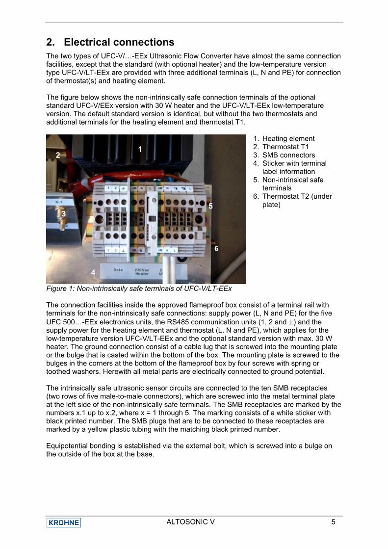
2. Electrical connections The two types of UFC-V/…-EEx Ultrasonic Flow Converter have almost the same connection facilities, except that the standard (with optional heater) and the low-temperature version type UFC-V/LT-EEx are provided with three additional terminals (L, N and PE) for connection of thermostat(s) and heating element. The figure below shows the non-intrinsically safe connection terminals of the optional standard UFC-V/EEx version with 30 W heater and the UFC-V/LT-EEx low-temperature version. The default standard version is identical, but without the two thermostats and additional terminals for the heating element and thermostat T1.
1. Heating element 2. Thermostat T1 3. SMB connectors 4. Sticker with terminal
label information 5. Non-intrinsical safe
terminals 6. Thermostat T2 (under
plate)
Figure 1: Non-intrinsically safe terminals of UFC-V/LT-EEx The connection facilities inside the approved flameproof box consist of a terminal rail with terminals for the non-intrinsically safe connections: supply power (L, N and PE) for the five UFC 500…-EEx electronics units, the RS485 communication units (1, 2 and ⊥) and the supply power for the heating element and thermostat (L, N and PE), which applies for the low-temperature version UFC-V/LT-EEx and the optional standard version with max. 30 W heater. The ground connection consist of a cable lug that is screwed into the mounting plate or the bulge that is casted within the bottom of the box. The mounting plate is screwed to the bulges in the corners at the bottom of the flameproof box by four screws with spring or toothed washers. Herewith all metal parts are electrically connected to ground potential. The intrinsically safe ultrasonic sensor circuits are connected to the ten SMB receptacles (two rows of five male-to-male connectors), which are screwed into the metal terminal plate at the left side of the non-intrinsically safe terminals. The SMB receptacles are marked by the numbers x.1 up to x.2, where x = 1 through 5. The marking consists of a white sticker with black printed number. The SMB plugs that are to be connected to these receptacles are marked by a yellow plastic tubing with the matching black printed number. Equipotential bonding is established via the external bolt, which is screwed into a bulge on the outside of the box at the base.
1 2
3
4
5
6
ALTOSONIC V 6
2.1 Equipotential bonding system The UFC-V/…-EEx Ultrasonic Flow Converter with cable glands must always be incorporated into the equipotential bonding system with the UFS 500 F/5STR-EEx 5-beam Flow Sensor. If the UFC-V/…-EEx is provided with metal rigid conduits, equipotential bonding is not required but can optional be connected. The bonding conductor must have a minimum cross-sectional area of 2.5 mm2 (equivalent to AWG 12) and is provided with a ring cable lug, which is screwed to the bulge at the base of the flameproof box via a stainless steel bolt with spring or toothed washer. Make sure that the bolt is tightly fixed.
2.2 Connecting cables The following cables are shown in the connection diagram: Cable A: Signal cable for RS485 communication. Cable parameters must be in accordance with the regulations in the EN 60079-14 "Electrical installations in hazardous locations" or an equivalent national standard (e.g. DIN VDE 0165). Cable B: Power supply cable. Cable parameters must be in accordance with the regulations in the EN 60079-14 "Electrical installations in hazardous locations" or an equivalent national standard (e.g. DIN VDE 0165). Rated voltage: ≥ 500 V Examples: H07..-., H05..-. Cable C: Quad coaxial cable. Type MR04 (supplied by KROHNE). Technical data: Test voltage: ≥ 500 V Diameter of strand (core and screen): ≥ 0.1 mm Distributed capacitance (core/screen): 67 pF/m Distributed inductance (core/screen): 0.4 µH/m Bonding conductor: Minimum cross-sectional area: ≥ 2.5 mm2 (equivalent to AWG 12)
ALTOSONIC V 7
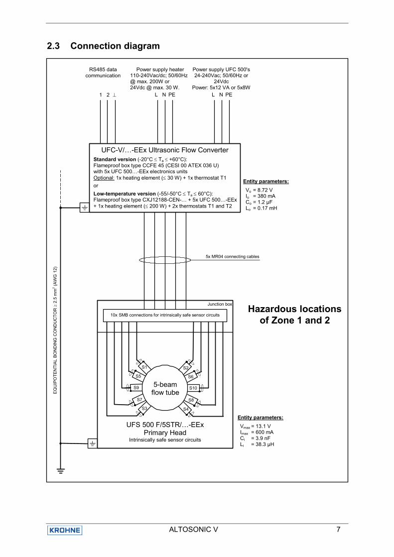
2.3 Connection diagram
Hazardous locationsof Zone 1 and 2
EQ
UIP
OTE
NTI
AL
BON
DIN
G C
ON
DU
CTO
R ≥
2.5
mm
2 (AW
G 1
2)
5x MR04 connecting cables
Entity parameters: Vo = 8.72 V Io = 380 mA Co = 1.2 µF Lo = 0.17 mH
RS485 data communication
UFC-V/…-EEx Ultrasonic Flow Converter
Standard version (-20°C ≤ Ta ≤ +60°C): Flameproof box type CCFE 45 (CESI 00 ATEX 036 U) with 5x UFC 500…-EEx electronics units Optional: 1x heating element (≤ 30 W) + 1x thermostat T1 or Low-temperature version (-55/-50°C ≤ Ta ≤ 60°C): Flameproof box type CXJ12188-CEN-… + 5x UFC 500…-EEx + 1x heating element (≤ 200 W) + 2x thermostats T1 and T2
L N PE 1 2 ⊥ L N PE
Power supply heater 110-240Vac/dc; 50/60Hz @ max. 200W or 24Vdc @ max. 30 W.
Power supply UFC 500's 24-240Vac; 50/60Hz or
24Vdc Power: 5x12 VA or 5x8W
Junction box
5-beam flow tube
S1
S5
S9
S7
S3
S2
S6
S10
S8
S4
UFS 500 F/5STR/…-EEx Primary Head
Intrinsically safe sensor circuits
10x SMB connections for intrinsically safe sensor circuits
Entity parameters: Vmax = 13.1 V Imax = 600 mA Ci = 3.9 nF Li = 38.3 µH
ALTOSONIC V 8
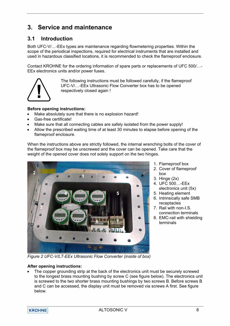
3. Service and maintenance
3.1 Introduction Both UFC-V/…-EEx types are maintenance regarding flowmetering properties. Within the scope of the periodical inspections, required for electrical instruments that are installed and used in hazardous classified locations, it is recommended to check the flameproof enclosure. Contact KROHNE for the ordering information of spare parts or replacements of UFC 500/…-EEx electronics units and/or power fuses.
The following instructions must be followed carefully, if the flameproof UFC-V/…-EEx Ultrasonic Flow Converter box has to be opened respectively closed again !
Before opening instructions: • Make absolutely sure that there is no explosion hazard! • Gas-free certificate! • Make sure that all connecting cables are safely isolated from the power supply! • Allow the prescribed waiting time of at least 30 minutes to elapse before opening of the
flameproof enclosure. When the instructions above are strictly followed, the internal wrenching bolts of the cover of the flameproof box may be unscrewed and the cover can be opened. Take care that the weight of the opened cover does not solely support on the two hinges.
1. Flameproof box 2. Cover of flameproof
box 3. Hinge (2x) 4. UFC 500…-EEx
electronics unit (5x) 5. Heating element 6. Intrinsically safe SMB
receptacles 7. Rail with non-I.S.
connection terminals 8. EMC-rail with shielding
terminals
Figure 2 UFC-V/LT-EEx Ultrasonic Flow Converter (inside of box) After opening instructions: • The copper grounding strip at the back of the electronics unit must be securely screwed
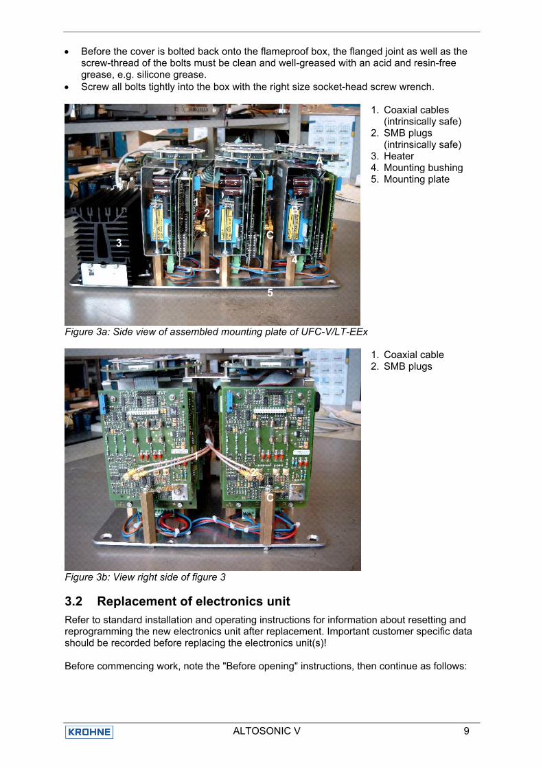
to the longest brass mounting bushing by screw C (see figure below). The electronics unit is screwed to the two shorter brass mounting bushings by two screws B. Before screws B and C can be accessed, the display unit must be removed via screws A first. See figure below.
1 2
3
4 5
6
7 6
8
ALTOSONIC V 9
• Before the cover is bolted back onto the flameproof box, the flanged joint as well as the screw-thread of the bolts must be clean and well-greased with an acid and resin-free grease, e.g. silicone grease.
• Screw all bolts tightly into the box with the right size socket-head screw wrench.
1. Coaxial cables (intrinsically safe)
2. SMB plugs (intrinsically safe)
3. Heater 4. Mounting bushing 5. Mounting plate
Figure 3a: Side view of assembled mounting plate of UFC-V/LT-EEx
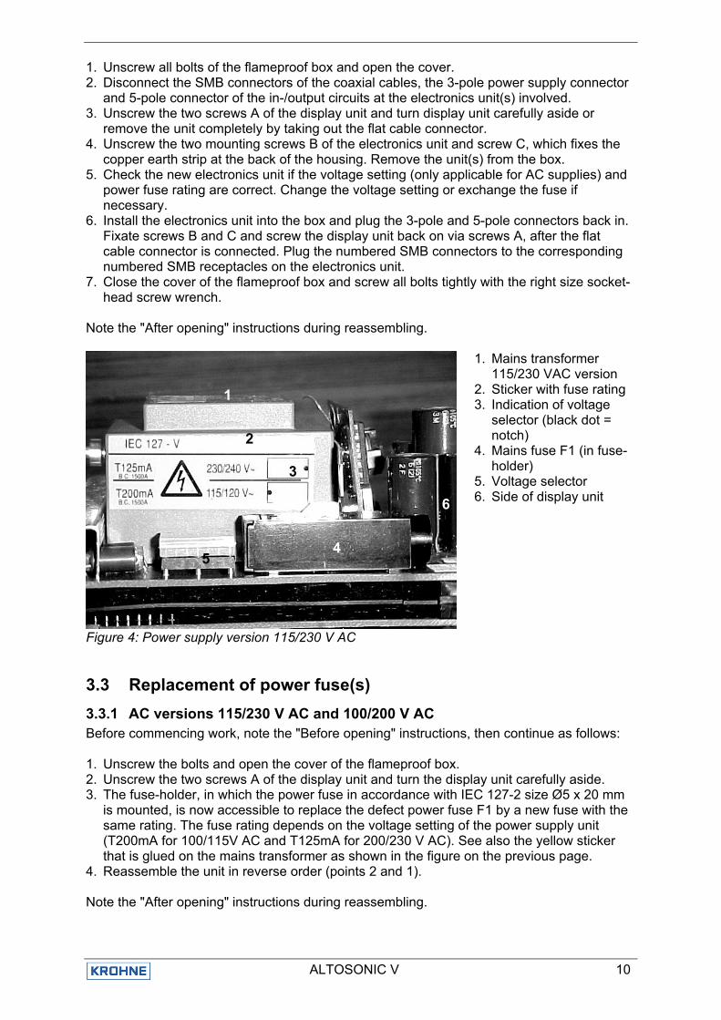
1. Coaxial cable 2. SMB plugs
Figure 3b: View right side of figure 3
3.2 Replacement of electronics unit Refer to standard installation and operating instructions for information about resetting and reprogramming the new electronics unit after replacement. Important customer specific data should be recorded before replacing the electronics unit(s)! Before commencing work, note the "Before opening" instructions, then continue as follows:
3
1 2
4
5
C
B
A
C
1 2
ALTOSONIC V 10
1. Unscrew all bolts of the flameproof box and open the cover. 2. Disconnect the SMB connectors of the coaxial cables, the 3-pole power supply connector
and 5-pole connector of the in-/output circuits at the electronics unit(s) involved. 3. Unscrew the two screws A of the display unit and turn display unit carefully aside or
remove the unit completely by taking out the flat cable connector. 4. Unscrew the two mounting screws B of the electronics unit and screw C, which fixes the
copper earth strip at the back of the housing. Remove the unit(s) from the box. 5. Check the new electronics unit if the voltage setting (only applicable for AC supplies) and
power fuse rating are correct. Change the voltage setting or exchange the fuse if necessary.
6. Install the electronics unit into the box and plug the 3-pole and 5-pole connectors back in. Fixate screws B and C and screw the display unit back on via screws A, after the flat cable connector is connected. Plug the numbered SMB connectors to the corresponding numbered SMB receptacles on the electronics unit.
7. Close the cover of the flameproof box and screw all bolts tightly with the right size socket-head screw wrench.
Note the "After opening" instructions during reassembling.
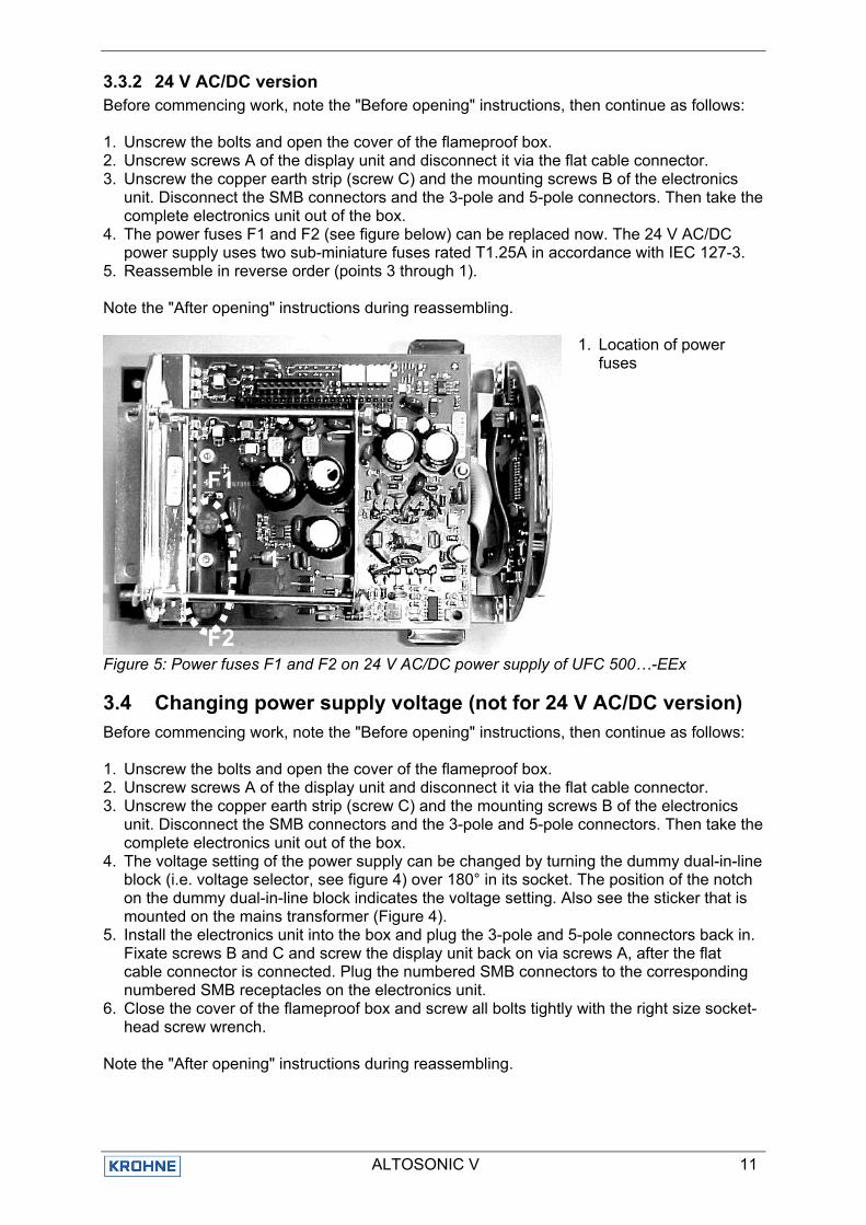
1. Mains transformer 115/230 VAC version
2. Sticker with fuse rating 3. Indication of voltage
selector (black dot = notch)
4. Mains fuse F1 (in fuse-holder)
5. Voltage selector 6. Side of display unit
Figure 4: Power supply version 115/230 V AC
3.3 Replacement of power fuse(s) 3.3.1 AC versions 115/230 V AC and 100/200 V AC Before commencing work, note the "Before opening" instructions, then continue as follows: 1. Unscrew the bolts and open the cover of the flameproof box. 2. Unscrew the two screws A of the display unit and turn the display unit carefully aside. 3. The fuse-holder, in which the power fuse in accordance with IEC 127-2 size Ø5 x 20 mm
is mounted, is now accessible to replace the defect power fuse F1 by a new fuse with the same rating. The fuse rating depends on the voltage setting of the power supply unit (T200mA for 100/115V AC and T125mA for 200/230 V AC). See also the yellow sticker that is glued on the mains transformer as shown in the figure on the previous page.
4. Reassemble the unit in reverse order (points 2 and 1). Note the "After opening" instructions during reassembling.
1
3
2
4 5
6
ALTOSONIC V 11
3.3.2 24 V AC/DC version Before commencing work, note the "Before opening" instructions, then continue as follows: 1. Unscrew the bolts and open the cover of the flameproof box. 2. Unscrew screws A of the display unit and disconnect it via the flat cable connector. 3. Unscrew the copper earth strip (screw C) and the mounting screws B of the electronics
unit. Disconnect the SMB connectors and the 3-pole and 5-pole connectors. Then take the complete electronics unit out of the box.
4. The power fuses F1 and F2 (see figure below) can be replaced now. The 24 V AC/DC power supply uses two sub-miniature fuses rated T1.25A in accordance with IEC 127-3.
5. Reassemble in reverse order (points 3 through 1). Note the "After opening" instructions during reassembling.
1. Location of power fuses
Figure 5: Power fuses F1 and F2 on 24 V AC/DC power supply of UFC 500…-EEx
3.4 Changing power supply voltage (not for 24 V AC/DC version) Before commencing work, note the "Before opening" instructions, then continue as follows: 1. Unscrew the bolts and open the cover of the flameproof box. 2. Unscrew screws A of the display unit and disconnect it via the flat cable connector. 3. Unscrew the copper earth strip (screw C) and the mounting screws B of the electronics
unit. Disconnect the SMB connectors and the 3-pole and 5-pole connectors. Then take the complete electronics unit out of the box.
4. The voltage setting of the power supply can be changed by turning the dummy dual-in-line block (i.e. voltage selector, see figure 4) over 180° in its socket. The position of the notch on the dummy dual-in-line block indicates the voltage setting. Also see the sticker that is mounted on the mains transformer (Figure 4).
5. Install the electronics unit into the box and plug the 3-pole and 5-pole connectors back in. Fixate screws B and C and screw the display unit back on via screws A, after the flat cable connector is connected. Plug the numbered SMB connectors to the corresponding numbered SMB receptacles on the electronics unit.
6. Close the cover of the flameproof box and screw all bolts tightly with the right size socket-head screw wrench.
Note the "After opening" instructions during reassembling.
1
F1
F2
ALTOSONIC V 12
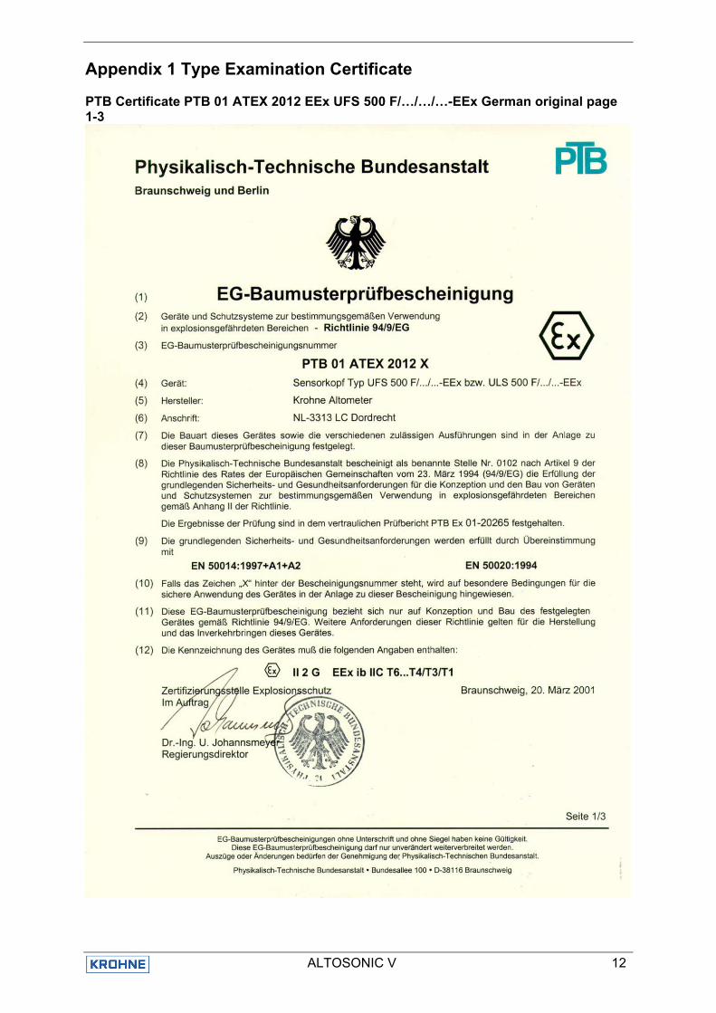
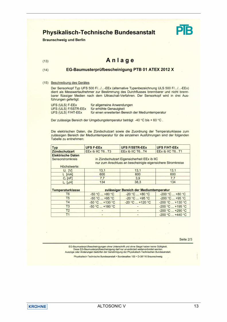
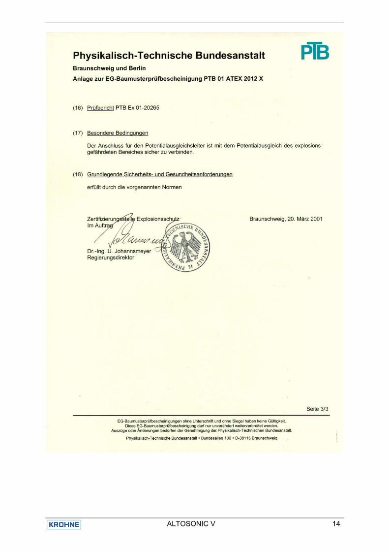
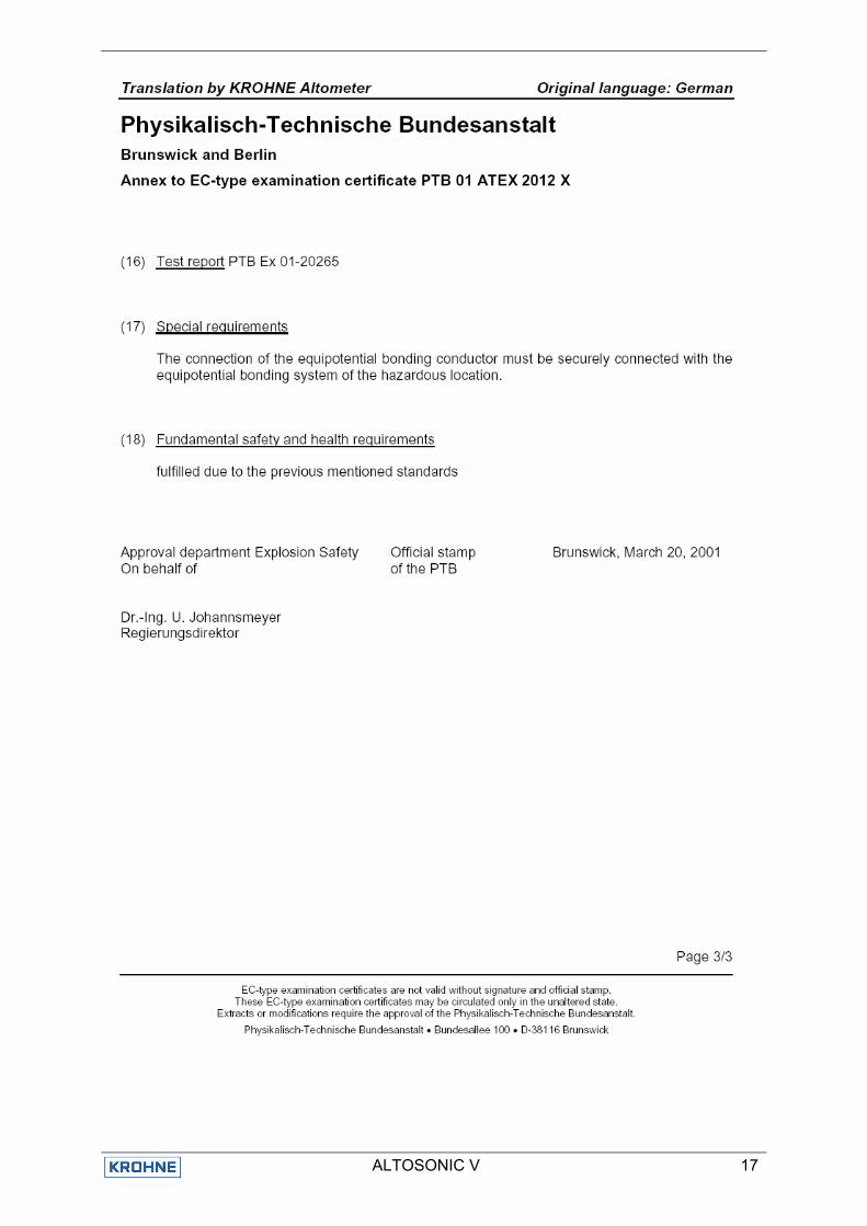
Appendix 1 Type Examination Certificate PTB Certificate PTB 01 ATEX 2012 EEx UFS 500 F/…/…/…-EEx German original page 1-3
ALTOSONIC V 13
ALTOSONIC V 14
ALTOSONIC V 15
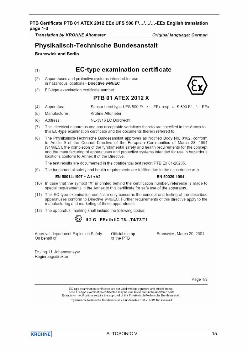
PTB Certificate PTB 01 ATEX 2012 EEx UFS 500 F/…/…/…-EEx English translation page 1-3
ALTOSONIC V 16
ALTOSONIC V 17
ALTOSONIC V 18
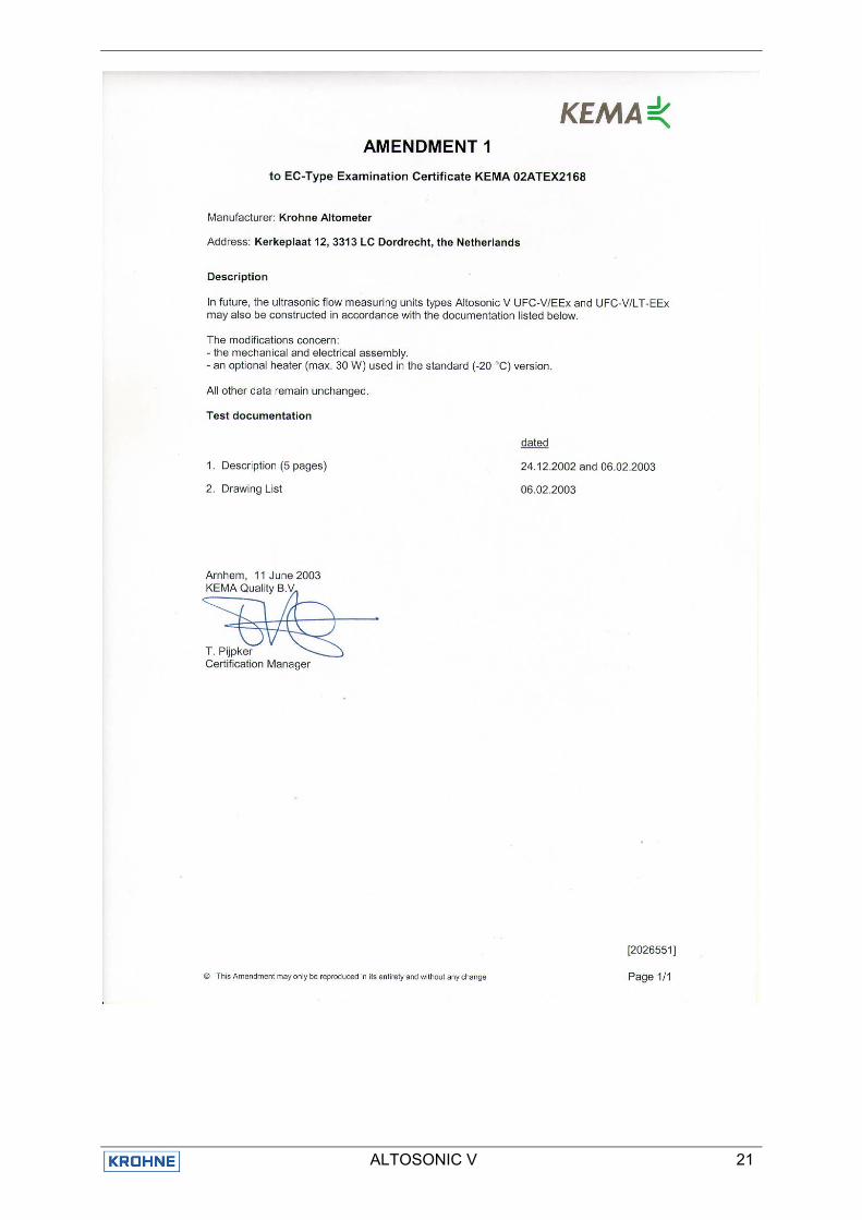
KEMA ATEX certificate 02ATEX2168 ALTOSONIC V UFC-V/EEx and UFC-V/LT-EEx

ALTOSONIC V 19
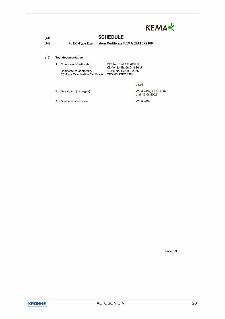
ALTOSONIC V 20
ALTOSONIC V 21
ALTOSONIC V 22
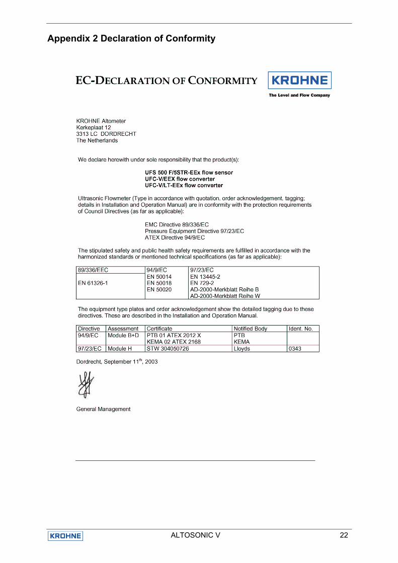
Appendix 2 Declaration of Conformity
ALTOSONIC V 23
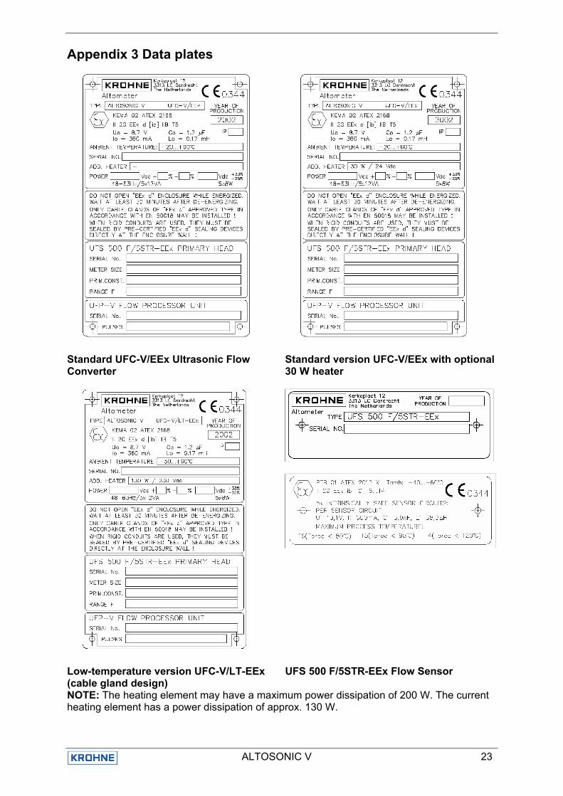
Appendix 3 Data plates
Standard UFC-V/EEx Ultrasonic Flow Converter
Standard version UFC-V/EEx with optional 30 W heater
Low-temperature version UFC-V/LT-EEx (cable gland design)
UFS 500 F/5STR-EEx Flow Sensor
NOTE: The heating element may have a maximum power dissipation of 200 W. The current heating element has a power dissipation of approx. 130 W.
AustraliaKROHNE Australia Pty Ltd.Unit 19 No.9, Hudson Ave.Castle Hill 2154, NSWTEL.: +61(0)2-98948711FAX: +61(0)2-98994855e-mail: [email protected]
AustriaKROHNE Austria Ges.m.b.H.Modecenterstraße 14A-1030 WienTEL.: +43(0)1/203 45 32FAX: +43(0)1/203 47 78e-mail: [email protected]
BelgiumKROHNE Belgium N.V.Brusselstraat 320B-1702 Groot BijgaardenTEL.: +32(0)2-4 66 00 10FAX: +32(0)2-4 66 08 00e-mail: [email protected]
BrazilKROHNE ConautControles Automaticos Ltda.Estrada Das Águas Espraiadas, 230 C.P. 5606835 - 080 EMBU - SPTEL.: +55(0)11-4785-2700FAX: +55(0)11-4785-2768e-mail: [email protected]
ChinaKROHNE Measurement Instruments Co. Ltd.Room 7E, Yi Dian Mansion746 Zhao Jia Bang RoadShanghai 200030TEL.: +86(0)21-64677163FAX: +86(0)21-64677166Cellphone: +86(0)139 1885890e-mail: [email protected]
CISKanex KROHNE Engineering AGBusiness-Centre Planeta, Office 403ul. Marxistskaja 3109147 Moscow/RussiaTEL.: +7(0)095-9117165FAX: +7(0)095-9117231e-mail: [email protected]
Czech RepublicKROHNE CZ, spol. s r.o.Sobesická 156CZ-63800 BrnoTEL.: +420 545 532 111FAX: +420 545 220 093e-mail: [email protected]
AlgeriaArgentinaBulgariaCamaroonCanadaChile ColumbiaCroatiaDenmarkEcuadorEgyptFinlandFrench AntillesGreeceGuineaHong KongHungaryIndonesiaIvory CoastIranIrelandIsrael
Japan JordanKuwaitMaroccoMauritiusMexicoNew ZealandPakistanPolandPortugalSaudi ArabiaSenegalSingaporeSlovakiaSloveniaSwedenTaiwanThailandTurkeyTunesiaVenezuelaYugoslavia
FranceKROHNE S.A.Usine des OrsBP 98F-26 103 Romans CedexTEL.: +33(0)4-75 05 44 00FAX: +33(0)4-75 05 00 48e-mail: [email protected]
GermanyKROHNE MesstechnikGmbH & Co. KGLudwig-Krohne-StraßeD-47058 DuisburgTEL.: +49(0)203-301-0FAX: +49(0)203-301 389e-mail: [email protected]
IndiaKROHNE Marshall Ltd.A-34/35, M.I.D.C.Industrial Area, H-Block,Pimpri Poona 411018TEL.: +91(0)20 -744 20 20FAX: +91(0)20 -744 20 40e-mail: [email protected]
ItalyKROHNE Italia Srl.Via V. Monti 75I-20145 MilanoTEL.: +39(0)2-4 30 06 61FAX: +39(0)2-43 00 66 66e-mail: [email protected]
KoreaHankuk KROHNE2 F, 599-1Banghwa-2-DongKangseo-KuSeoulTEL.: +82(0)2665-85 23-4FAX: +82(0)2665-85 25e-mail: [email protected]
NetherlandsKROHNE AltometerKerkeplaat 12 NL-3313 LC DordrechtTEL.: +31(0)78-6306300FAX: +31(0)78-6306390e-mail: [email protected]
KROHNE Nederland B.V.Kerkeplaat 12NL-3313 LC DordrechtTEL.: +31(0)78-6306200FAX: +31(0)78-6306405Service Direkt: +31(0)78-6306222e-mail: [email protected]
NorwayKROHNEInstrumentation A.S.Ekholtveien 114 NO-1526 MossP.O. Box 2178, NO-1521 MossTEL.: +47(0)69-264860FAX: +47(0)69-267333e-mail: [email protected]: www.krohne.no
South AfricaKROHNE Pty. Ltd.163 New RoadHalfway House Ext. 13MidrandTEL.: +27(0)11-315-2685FAX: +27(0)11-805-0531e-mail: [email protected]
SpainI.I. KROHNE Iberia, S.r.L.Poligono Industrial NiloCalle Brasil, n°. 5E-28806 Alcalá de Henares -MadridTEL.: +34(0)91-8 83 21 52FAX: +34(0)91-8 83 48 54e-mail: [email protected]
SwitzerlandKROHNE AGUferstr. 90CH-4019 BaselTEL.: +41(0)61-638 30 30FAX: +41(0)61-638 30 40e-mail: [email protected]
United KingdomKROHNE Ltd.Rutherford DrivePark Farm Industrial EstateWellingborough,Northants NN8 6AE, UKTEL.: +44(0)19 33-408 500FAX: +44(0)19 33-408 501e-mail: [email protected]
USAKROHNE Inc.7 Dearborn RoadPeabody, MA 01960TEL.: +1-978 535-6060FAX: +1-978 535-1720e-mail: [email protected]
Overseas Representatives
NetherlandsKROHNE Oil & Gas B.V.Kerkeplaat 18NL-3313 LC DordrechtTel: +31(0)78 - 63 06 300Fax: +31(0)78 - 63 06 404E-mail: [email protected]
Subject to change without notice