Embed Size (px)
Citation preview
© KROHNE 09/2008 7.30855.35.00
Ultrasonic Flowmeters
ALTOSONIC V
Reference Guide
Modbus manual Protocol description
& setup
Applicable for software version 0300
ALTOSONIC V
ModBus Manual 0300 rev07 E 7.30855.35.00 Page 2 of 64
TABLE OF CONTENTS
1 INTRODUCTION TO MODBUS.................................................................................................... 5
2 SERIAL TRANSMISSION FORMAT ............................................................................................ 6
2.1 ASCII-MODE ................................................................................................................................... 6 2.2 RTU-MODE ..................................................................................................................................... 6
3 MODBUS MESSAGE FRAMING.................................................................................................. 7
3.1 THE ADDRESS FIELD ....................................................................................................................... 7 3.2 THE FUNCTION FIELD ...................................................................................................................... 7 3.3 THE DATA FIELD.............................................................................................................................. 7 3.4 THE ERROR CHECKING FIELD .......................................................................................................... 8 3.5 OTHER ERROR CHECKING METHODS ............................................................................................... 8
4 PHYSICAL COMMUNICATION LAYER....................................................................................... 9
4.1 WHEN USING RS232 TO RS485 CONVERTERS ................................................................................. 9 4.2 WHEN USING SERIAL I/O CARDS WITH RS485 DRIVERS ..................................................................... 9
5 SUPPORTED FUNCTIONS........................................................................................................ 10
5.1 FUNCTION 01: READ COIL STATUS ............................................................................................ 10 5.2 FUNCTION 02: READ INPUT STATUS.......................................................................................... 11 5.3 FUNCTION 03: READ MULTIPLE HOLDING REGISTERS........................................................... 11 5.4 FUNCTION 04: READ INPUT REGISTERS ................................................................................... 12 5.5 FUNCTION 05: WRITE SINGLE COIL ........................................................................................... 12 5.6 FUNCTION 06: WRITE SINGLE HOLDING REGISTER................................................................ 12 5.7 FUNCTION 8: DIAGNOSTICS........................................................................................................ 13 5.8 FUNCTION 15: WRITE MULTIPLE COILS .................................................................................... 13 5.9 FUNCTION 16: WRITE MULTIPLE HOLDING REGISTERS ......................................................... 14 5.10 EXCEPTION RESPONSES............................................................................................................ 15
6 HANDLING OF LARGE DATA TYPES ...................................................................................... 16
6.1 FLOATING POINT REPRESENTATION ............................................................................................... 17 6.2 DOUBLE REPRESENTATION ............................................................................................................ 17 6.3 TRANSMIT SEQUENCE.................................................................................................................... 17 6.4 MAXIMUM REQUESTED POINTS ....................................................................................................... 18
7 SET-UP OF THE UFP-V MODBUS DRIVER ............................................................................. 20
7.1 DRIVER CONTENTS........................................................................................................................ 20 7.2 HARDWARE SET-UP ....................................................................................................................... 20
7.2.1 RS485/422 card: AX4285A............................................................................................................ 21 7.2.2 RS485/422 card: PCL-745 S ......................................................................................................... 22
7.3 SOFTWARE SET-UP ....................................................................................................................... 23 7.3.1 First set the parameters for the communication line...................................................................... 23 7.3.2 Now select the parameters for the used protocol .......................................................................... 23 7.3.3 The UFP-V as SLAVE device ........................................................................................................ 23 7.3.4 The UFP-V as Master .................................................................................................................... 24
7.4 WHAT CAN GO WRONG? ................................................................................................................ 25 7.5 HOW STATUS FLAGS ARE UPDATED ............................................................................................... 25 7.6 HOW DATA IS WRITTEN TO THE FLOAT FIELD.................................................................................... 27
7.6.1 How to write in the float field to the specific application ................................................................ 27
8 MODBUS MAPPING ASSIGNMENTS ....................................................................................... 29
8.1 FIELD 0 (READ ONLY BOOLEAN FIELD) ............................................................................................ 29 8.2 FIELD 1 (READ/WRITE BOOLEAN FIELD) ......................................................................................... 31 8.3 FIELD 2 (READ ONLY INTEGER FIELD) ............................................................................................. 35 8.4 FIELD 3 (READ ONLY LONG INTEGER FIELD).................................................................................... 38 8.5 FIELD 4 (READ ONLY FLOAT FIELD) ................................................................................................ 40 8.6 FIELD 5 (READ ONLY DOUBLE FIELD).............................................................................................. 45 8.7 FIELD 6 (READ/WRITE FLOAT FIELD).............................................................................................. 46

ALTOSONIC V
ModBus Manual 0300 rev07 E 7.30855.35.00 Page 3 of 64
8.8 FIELD 6 (READ ONLY ASCII FIELD 8 CHARACTERS) ........................................................................ 49 8.9 FIELD 6 (READ WRITE ASCII FIELD 16 CHARACTERS)..................................................................... 49 8.10 EXPLANATION OF DATA AVAILABLE TO MODBUS ......................................................................... 51 8.11 THE SYSTEM MESSAGES ........................................................................................................... 55
9 APPENDICES ............................................................................................................................. 57
9.1 APPENDIX A: TIME OUT VALUES...................................................................................................... 57 9.2 APPENDIX B: LRC GENERATION..................................................................................................... 58 9.3 APPENDIX C: CRC GENERATION .................................................................................................... 59 9.4 APPENDIX D: COMS0300.DAT ........................................................................................................ 62
ALTOSONIC V
ModBus Manual 0300 rev07 E 7.30855.35.00 Page 4 of 64
INTRODUCTION This manual describes how to use the Modbus protocol with the ALTOSONIC V flow meter system. Product Liability and warranty Responsibility for suitability and intented use of these ultrasonic flowmeters rests solely with the operator. Improper installation and operation of the flowmeters (systems) may lead to loss of warranty. In addition, the “General conditions of sale” forming the basis of the purchase contract are applicable. Nothing from this document may be copied or reproduced without the written permission of KROHNE Altometer
ALTOSONIC V
ModBus Manual 0300 rev07 E 7.30855.35.00 Page 5 of 64
1 INTRODUCTION TO MODBUS From this point in the manual the following abbreviations are used for the ALTOSONIC-V system: UFS-V: Ultrasonic Flow Sensor (primary flow meter body) UFC-V: Ultrasonic Flow Converter (5 converters) UFP-V: Ultrasonic Flow Processor Introduction to Modbus For communication with host systems the flow controller emulates a Modbus compatible controller. The Modbus protocol defines a message structure that controllers will recognise and use, regardless of the type of network over which they communicate. It describes: • the process a controller uses to request access to other devices, • how it will respond to requests from the other devices, and • how errors will be detected and reported. Controllers communicate using a master-slave principle. Only the master can initiate transactions (requests), and only the addressed device responds. In case of a broadcast request none of the slaves will respond. The Modbus request consist of: • an address, • a function code defining the requested action, • data (if necessary for the requested function), and • error check for testing the integrity of the message. The slave’s response contains: • the slave address, • data conform the request type, and • error check.
If the data integrity test fails, no response is sent back. If a request cannot be processed an exception message is returned.

ALTOSONIC V
ModBus Manual 0300 rev07 E 7.30855.35.00 Page 6 of 64
2 SERIAL TRANSMISSION FORMAT The two transmission modes used are called: 1. ASCII, and 2. RTU. The user has to select the desired mode along with the serial communication parameters (baud rate, parity-type). Note that all these parameters must be the same for all controllers in the network.
2.1 ASCII-mode
• Each byte of the message is sent as two ASCII characters. This means only the ASCII characters 0-9, A-F are transmitted.
• Serial communication parameters: 1 start byte, 7 data bits, even/odd/no parity, 1 stop bit if parity is used and two stop bits if no parity is used.
• Error check field: Longitudinal Redundancy Check (LRC).
The advantage of ASCII mode is that it allows for a time interval up to 1 second between characters without causing a timeout. A disadvantage of ASCII mode is the larger message length.
2.2 RTU-mode
• Each byte of the message is sent as 8 bits. • Serial communication parameters:
1 start byte, 8 data bits, even/odd/no parity, 1 stop bit if parity is used, and two stop bits if no parity is used.
• Error check field: Cyclic Redundancy Check (CRC).
ALTOSONIC V
ModBus Manual 0300 rev07 E 7.30855.35.00 Page 7 of 64
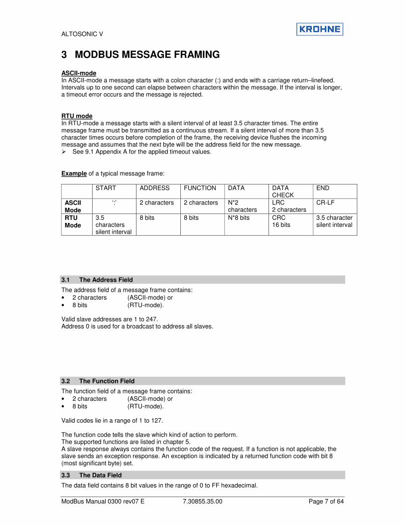
3 MODBUS MESSAGE FRAMING ASCII-mode In ASCII-mode a message starts with a colon character (:) and ends with a carriage return–linefeed. Intervals up to one second can elapse between characters within the message. If the interval is longer, a timeout error occurs and the message is rejected. RTU mode In RTU-mode a message starts with a silent interval of at least 3.5 character times. The entire message frame must be transmitted as a continuous stream. If a silent interval of more than 3.5 character times occurs before completion of the frame, the receiving device flushes the incoming message and assumes that the next byte will be the address field for the new message. � See 9.1 Appendix A for the applied timeout values. Example of a typical message frame: START
ADDRESS FUNCTION DATA
DATA CHECK
END
ASCII Mode
‘:’ 2 characters 2 characters N*2 characters
LRC 2 characters
CR-LF
RTU
Mode
3.5 characters silent interval
8 bits 8 bits N*8 bits CRC 16 bits
3.5 character silent interval
3.1 The Address Field
The address field of a message frame contains: • 2 characters (ASCII-mode) or • 8 bits (RTU-mode). Valid slave addresses are 1 to 247. Address 0 is used for a broadcast to address all slaves.
3.2 The Function Field
The function field of a message frame contains: • 2 characters (ASCII-mode) or • 8 bits (RTU-mode). Valid codes lie in a range of 1 to 127. The function code tells the slave which kind of action to perform. The supported functions are listed in chapter 5. A slave response always contains the function code of the request. If a function is not applicable, the slave sends an exception response. An exception is indicated by a returned function code with bit 8 (most significant byte) set.
3.3 The Data Field
The data field contains 8 bit values in the range of 0 to FF hexadecimal.
ALTOSONIC V
ModBus Manual 0300 rev07 E 7.30855.35.00 Page 8 of 64
In ASCII mode this byte is made of 2 ASCII characters. The data field of messages contains information which both master and slave use to perform an action. This includes the register address, quantity of registers, and the necessary data.
3.4 The Error Checking Field
The error checking field contents depend on the transmission mode. Two kinds of error methods are used. Error check with ASCII-mode When the ASCII mode is used, the error-checking field contains two ASCII characters. The error check characters are the result of a Longitudinal Redundancy Check calculation. This is performed on the message contents with exception of the beginning colon, the carriage return and line feed characters. The LRC characters are appended to the message as the last field preceding the CR-LF characters. � See 9.2 Appendix B for more information about the Longitudinal Redundancy Check. Error check with RTU-mode When RTU mode is used, the error-checking field contains a 16-bit value implemented as two bytes. The error check value is the result of a Cyclic Redundancy Check calculation performed on the message contents. The CRC field is appended to the message as the last field. � See 9.3 Appendix C for more information about the Cyclic Redundancy Check.
3.5 Other Error Checking Methods
Standard Modbus uses two kinds of error checking methods: 1. Character based check
an additional parity bit for each character (even or odd parity). 2. Message based check
an additional error check calculated over the entire message. Both character check and message check are generated in the transmitting device and applied to the message before transmission. The slave checks each character and the entire message frame during receipt. The master has a predetermined timeout interval before aborting the transaction. This interval is set long enough for any slave to respond normally. The timeout interval is set by the parameter 7.2 REQUEST_TO_RESPONSE_TIMEOUT. ASCII mode In ASCII mode the maximum time between 2 characters is one second. If a longer interval occurs, the message will be rejected and the search for a starting character (colon) is resumed. RTU mode In RTU mode the entire message frame must be transmitted as a continuous stream. If a silent interval of more than 3.5 character times occurs before completion of the frame, the receiving device flushes the incoming message and assumes that the next byte will be the address field for the new message.
ALTOSONIC V
ModBus Manual 0300 rev07 E 7.30855.35.00 Page 9 of 64
4 PHYSICAL COMMUNICATION LAYER The Modbus protocol is a half-duplex protocol. The physical layer can be half or full duplex. The Modbus driver supports both half (RS485) and full (RS232/RS422) duplex communication layers. In case of RS485, the parameter 3.8 MODBUS_UART_HALF_DUPLEX must be turned on. The transmitter is activated when the UFP-V transmits data. The RS485 receiver may not be disabled e.g. the transmitted data must also be received by the UFP-V for correct functioning!
4.1 When using RS232 to RS485 converters
• Always use isolated converters! • Use the types that enable the transmitter by means of the Request To Send signal. • Use the parameter 3.4 MODBUS_UART_RTS_MODE to define whether a high or a low level
enables the transmitter. • Check if the terminator resistor corresponds with the characteristic line impedance. • Use pull-up and pull down resistors for fail safe operation. • If possible, use the Serial Communication port that uses Interrupt Request 3.
4.2 When using serial I/O cards with RS485 drivers
• Use the types that enable the transmitter by means of the Request To Send signal. • Use the parameter 3.4 MODBUS_UART_RTS_MODE to define whether a high or a low level
enables the transmitter. • Check if the terminator resistor corresponds with the characteristic line impedance. • Use pull-up and pull down resistors for fail safe operation. • Set the IO-address and Interrupt number to the correct values. • When possible, use Interrupt Request 3.
ALTOSONIC V
ModBus Manual 0300 rev07 E 7.30855.35.00 Page 10 of 64
5 SUPPORTED FUNCTIONS All data addresses in Modbus messages are referenced to zero. For example: • Coil 1 is addressed as Coil 0000. • Holding register 40001 is addressed as 0000. Note that the function code specifies the operation of
a ‘holding register’, therefore the 4xxxx reference is implicit. When functions which do not support broadcast requests, are accessed with a broadcast address, the request will be rejected.
5.1 Function 01: READ COIL STATUS
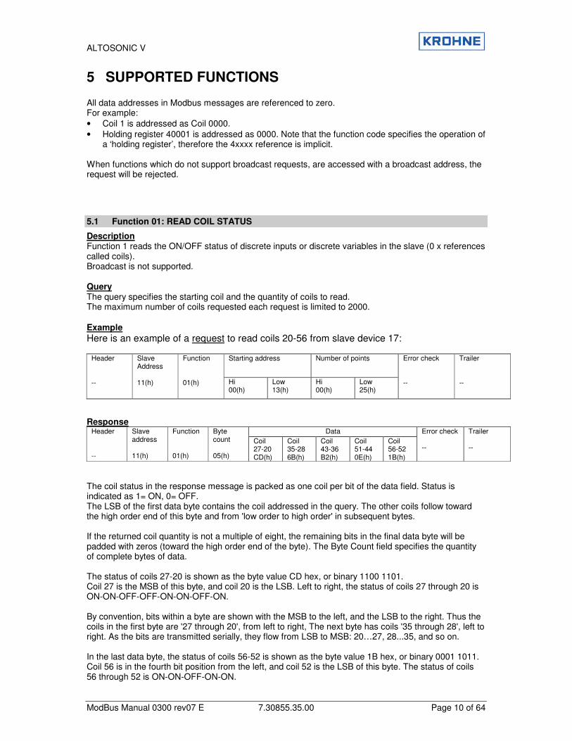
Description Function 1 reads the ON/OFF status of discrete inputs or discrete variables in the slave (0 x references called coils). Broadcast is not supported. Query The query specifies the starting coil and the quantity of coils to read. The maximum number of coils requested each request is limited to 2000.
Example
Here is an example of a request to read coils 20-56 from slave device 17:
Starting address Number of points Header --
Slave Address 11(h)
Function 01(h) Hi
00(h) Low 13(h)
Hi 00(h)
Low 25(h)
Error check --
Trailer --
Response
Data Header --
Slave address 11(h)
Function 01(h)
Byte count 05(h)
Coil 27-20 CD(h)
Coil 35-28 6B(h)
Coil 43-36 B2(h)
Coil 51-44 0E(h)
Coil 56-52 1B(h)
Error check --
Trailer --
The coil status in the response message is packed as one coil per bit of the data field. Status is indicated as 1= ON, 0= OFF. The LSB of the first data byte contains the coil addressed in the query. The other coils follow toward the high order end of this byte and from 'low order to high order' in subsequent bytes. If the returned coil quantity is not a multiple of eight, the remaining bits in the final data byte will be padded with zeros (toward the high order end of the byte). The Byte Count field specifies the quantity of complete bytes of data. The status of coils 27-20 is shown as the byte value CD hex, or binary 1100 1101. Coil 27 is the MSB of this byte, and coil 20 is the LSB. Left to right, the status of coils 27 through 20 is ON-ON-OFF-OFF-ON-ON-OFF-ON. By convention, bits within a byte are shown with the MSB to the left, and the LSB to the right. Thus the coils in the first byte are '27 through 20', from left to right, The next byte has coils '35 through 28', left to right. As the bits are transmitted serially, they flow from LSB to MSB: 20…27, 28...35, and so on. In the last data byte, the status of coils 56-52 is shown as the byte value 1B hex, or binary 0001 1011. Coil 56 is in the fourth bit position from the left, and coil 52 is the LSB of this byte. The status of coils 56 through 52 is ON-ON-OFF-ON-ON.
ALTOSONIC V
ModBus Manual 0300 rev07 E 7.30855.35.00 Page 11 of 64
Note how the three remaining bits (toward the high order end) are zero-filled. If the request is not applicable an exception response will be sent. � See chapter 5.10 for exception responses.
5.2 Function 02: READ INPUT STATUS
In the UFP-V Modbus protocol, function 1 and 2 perform the same processing and are interchangeable.
5.3 Function 03: READ MULTIPLE HOLDING REGISTERS
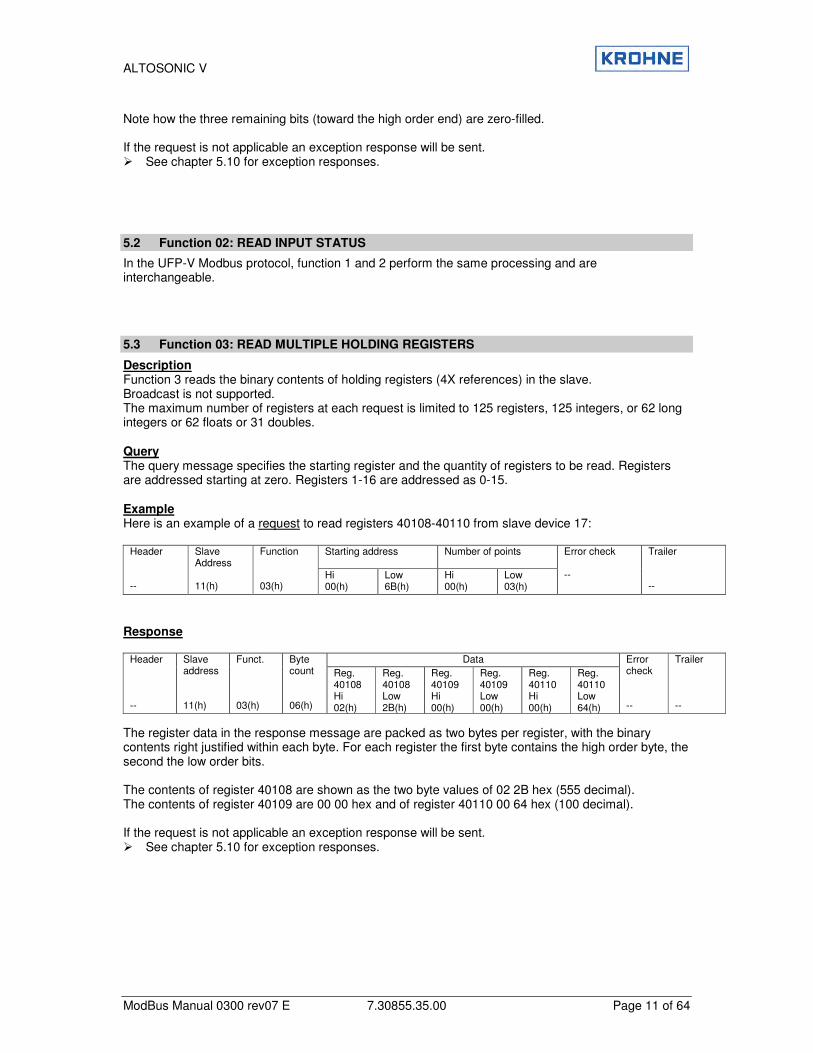
Description Function 3 reads the binary contents of holding registers (4X references) in the slave. Broadcast is not supported. The maximum number of registers at each request is limited to 125 registers, 125 integers, or 62 long integers or 62 floats or 31 doubles. Query The query message specifies the starting register and the quantity of registers to be read. Registers are addressed starting at zero. Registers 1-16 are addressed as 0-15. Example Here is an example of a request to read registers 40108-40110 from slave device 17:
Starting address Number of points Header --
Slave Address 11(h)
Function 03(h)
Hi 00(h)
Low 6B(h)
Hi 00(h)
Low 03(h)
Error check --
Trailer --
Response
Data Header --
Slave address 11(h)
Funct. 03(h)
Byte count 06(h)
Reg. 40108 Hi 02(h)
Reg. 40108 Low 2B(h)
Reg. 40109 Hi 00(h)
Reg. 40109 Low 00(h)
Reg. 40110 Hi 00(h)
Reg. 40110 Low 64(h)
Error check --
Trailer --
The register data in the response message are packed as two bytes per register, with the binary contents right justified within each byte. For each register the first byte contains the high order byte, the second the low order bits. The contents of register 40108 are shown as the two byte values of 02 2B hex (555 decimal). The contents of register 40109 are 00 00 hex and of register 40110 00 64 hex (100 decimal). If the request is not applicable an exception response will be sent. � See chapter 5.10 for exception responses.

ALTOSONIC V
ModBus Manual 0300 rev07 E 7.30855.35.00 Page 12 of 64
5.4 Function 04: READ INPUT REGISTERS
In the UFP-V Modbus protocol, function 3 and 4 perform the same processing and are interchangeable.
5.5 Function 05: WRITE SINGLE COIL
Description Function 5 forces a single coil to either ON or OFF (0x reference). When the address is a broadcast, all slaves will process the request. Query The query message specifies the coil reference to be forced. Coils are addressed starting at zero (coil 1 is addressed as zero). The requested ON/OFF status is specified by a constant in the query data field. A value of FF 00 hex requests the coil to be ON. A value of 00 00 requests it to be OFF. All other values are illegal and do not affect the coil and generate an exception. Example Here is an example of a request to force coil 173 ON in slave device 17.
Coil Address Data Header --
Slave Address 11(h)
Function 05(h)
Hi 00(h)
Low AC(h)
Hi FF(h)
Low 00(h)
Error Check --
Trailer --
The normal response is an echo of the query, returned after the coils state has been forced.
Coil Address Data Header --
Slave Address 11(h)
Function 05(h)
Hi 00(h)
Low AC(h)
Hi FF(h)
Low 00(h)
Error Check --
Trailer --
If the request is not applicable an exception response will be sent. � See chapter 5.10 for exception responses.
5.6 Function 06: WRITE SINGLE HOLDING REGISTER
Description Function 6 pre-sets a value into a single holding register (4x reference). When the address is a broadcast, all slaves will process the request. Query The query specifies the register reference to be preset. Registers are starting at address zero. The requested value (preset) is specified in the query data field, which is a 16-bit value.
ALTOSONIC V
ModBus Manual 0300 rev07 E 7.30855.35.00 Page 13 of 64
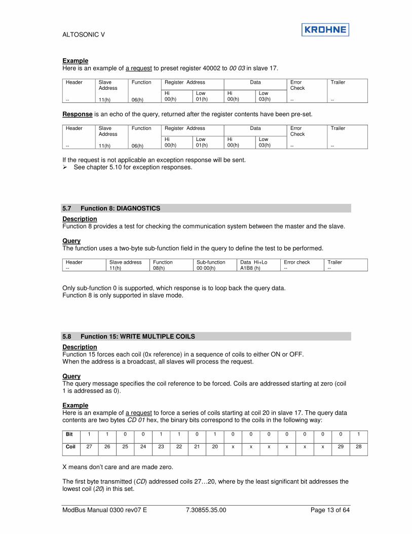
Example Here is an example of a request to preset register 40002 to 00 03 in slave 17.
Register Address Data Header --
Slave Address 11(h)
Function 06(h)
Hi 00(h)
Low 01(h)
Hi 00(h)
Low 03(h)
Error Check --
Trailer --
Response is an echo of the query, returned after the register contents have been pre-set.
Register Address Data Header --
Slave Address 11(h)
Function 06(h)
Hi 00(h)
Low 01(h)
Hi 00(h)
Low 03(h)
Error Check --
Trailer --
If the request is not applicable an exception response will be sent. � See chapter 5.10 for exception responses.
5.7 Function 8: DIAGNOSTICS
Description Function 8 provides a test for checking the communication system between the master and the slave. Query The function uses a two-byte sub-function field in the query to define the test to be performed.
Header --
Slave address 11(h)
Function 08(h)
Sub-function 00 00(h)
Data Hi+Lo A1B8 (h)
Error check --
Trailer --
Only sub-function 0 is supported, which response is to loop back the query data. Function 8 is only supported in slave mode.
5.8 Function 15: WRITE MULTIPLE COILS
Description Function 15 forces each coil (0x reference) in a sequence of coils to either ON or OFF. When the address is a broadcast, all slaves will process the request. Query The query message specifies the coil reference to be forced. Coils are addressed starting at zero (coil 1 is addressed as 0). Example Here is an example of a request to force a series of coils starting at coil 20 in slave 17. The query data contents are two bytes CD 01 hex, the binary bits correspond to the coils in the following way:
Bit
1 1 0 0 1 1 0 1 0 0 0 0 0 0 0 1
Coil
27 26 25 24 23 22 21 20 x x x x x x 29 28
X means don’t care and are made zero. The first byte transmitted (CD) addressed coils 27…20, where by the least significant bit addresses the lowest coil (20) in this set.
ALTOSONIC V
ModBus Manual 0300 rev07 E 7.30855.35.00 Page 14 of 64
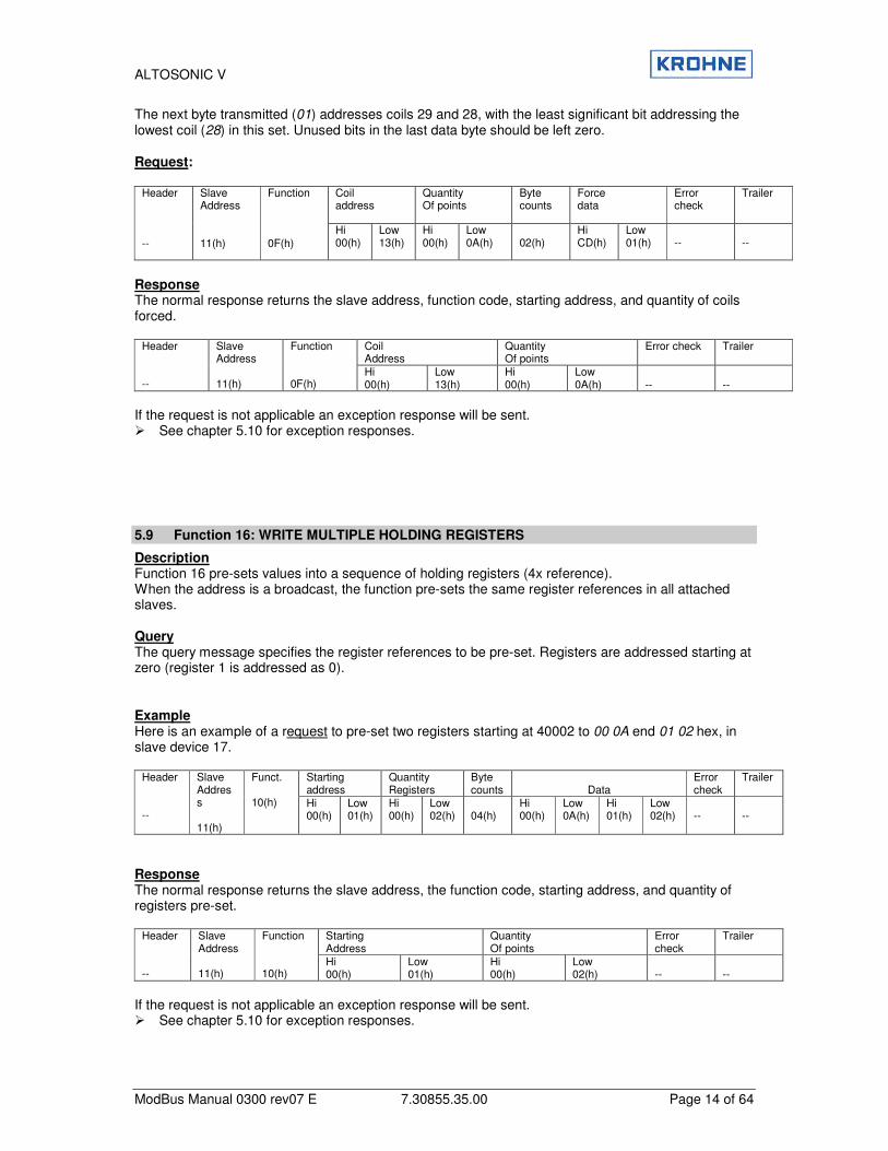
The next byte transmitted (01) addresses coils 29 and 28, with the least significant bit addressing the lowest coil (28) in this set. Unused bits in the last data byte should be left zero. Request:
Coil address
Quantity Of points
Byte counts
Force data
Error check
Trailer
Header --
Slave Address 11(h)
Function 0F(h)
Hi 00(h)
Low 13(h)
Hi 00(h)
Low 0A(h)
02(h)
Hi CD(h)
Low 01(h)
--
--
Response The normal response returns the slave address, function code, starting address, and quantity of coils forced.
Coil Address
Quantity Of points
Error check Trailer
Header --
Slave Address 11(h)
Function 0F(h)
Hi 00(h)
Low 13(h)
Hi 00(h)
Low 0A(h)
--
--
If the request is not applicable an exception response will be sent. � See chapter 5.10 for exception responses.
5.9 Function 16: WRITE MULTIPLE HOLDING REGISTERS
Description Function 16 pre-sets values into a sequence of holding registers (4x reference). When the address is a broadcast, the function pre-sets the same register references in all attached slaves. Query The query message specifies the register references to be pre-set. Registers are addressed starting at zero (register 1 is addressed as 0). Example Here is an example of a request to pre-set two registers starting at 40002 to 00 0A end 01 02 hex, in slave device 17.
Starting address
Quantity Registers
Byte counts
Data
Error check
Trailer
Header --
Slave Address 11(h)
Funct. 10(h) Hi
00(h) Low 01(h)
Hi 00(h)
Low 02(h)
04(h)
Hi 00(h)
Low 0A(h)
Hi 01(h)
Low 02(h)
--
--
Response The normal response returns the slave address, the function code, starting address, and quantity of registers pre-set.
Starting Address
Quantity Of points
Error check
Trailer
Header --
Slave Address 11(h)
Function 10(h)
Hi 00(h)
Low 01(h)
Hi 00(h)
Low 02(h)
--
--
If the request is not applicable an exception response will be sent. � See chapter 5.10 for exception responses.
ALTOSONIC V
ModBus Manual 0300 rev07 E 7.30855.35.00 Page 15 of 64
5.10 Exception Responses
Except for broadcast messages, a master device expects a normal response, when it sends a query to a slave device. One of the four possible events can occur from the master’s query: 1. If the slave device receives the query without a communication error and can handle the query
normally, it returns a normal response. 2. If the slave does not receive the query due to a communication error, no response is returned. The
master program will eventually process a timeout condition for the query. 3. If the slave receives the query, but detects a communication error (parity, CRC, LRC), no response
is returned. The master program will eventually process a timeout condition for the query. 4. If the slave receives the query without a communication error, but cannot handle it, the slave will
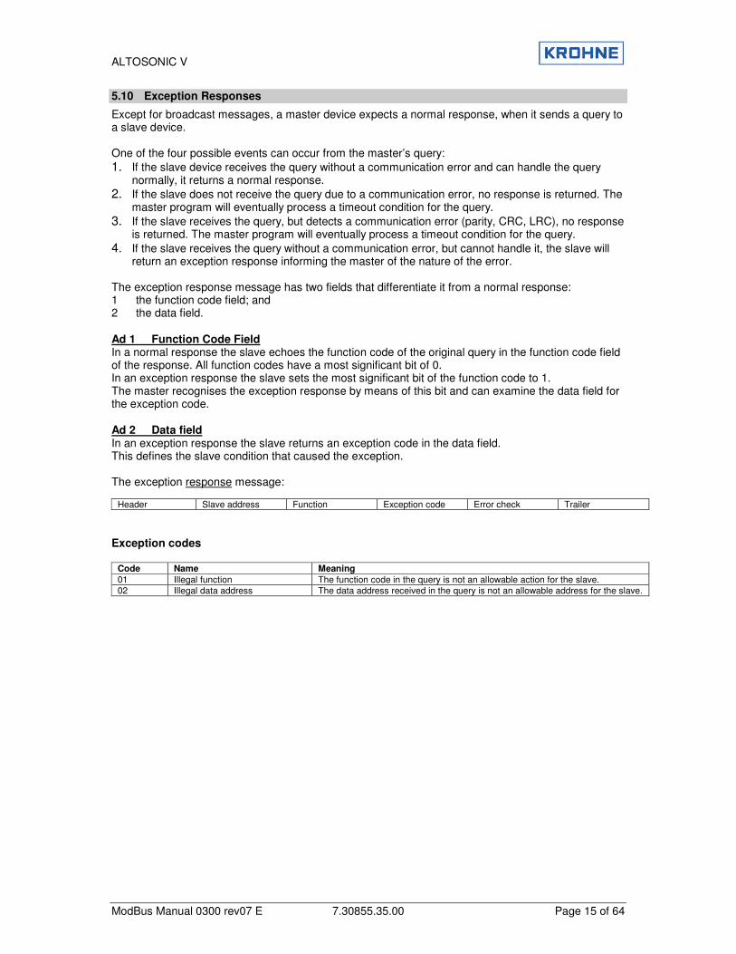
return an exception response informing the master of the nature of the error. The exception response message has two fields that differentiate it from a normal response: 1 the function code field; and 2 the data field. Ad 1 Function Code Field In a normal response the slave echoes the function code of the original query in the function code field of the response. All function codes have a most significant bit of 0. In an exception response the slave sets the most significant bit of the function code to 1. The master recognises the exception response by means of this bit and can examine the data field for the exception code. Ad 2 Data field In an exception response the slave returns an exception code in the data field. This defines the slave condition that caused the exception. The exception response message:
Header Slave address Function Exception code Error check Trailer Exception codes
Code Name Meaning
01 Illegal function The function code in the query is not an allowable action for the slave. 02 Illegal data address The data address received in the query is not an allowable address for the slave.

ALTOSONIC V
ModBus Manual 0300 rev07 E 7.30855.35.00 Page 16 of 64
6 HANDLING OF LARGE DATA TYPES The standard Modbus specification does not explain how data types larger than 16 bits should be handled. The standard Modbus functions to modify holding registers are used for handling larger data types. Function 03 (read multiple holding registers), function 06 (write single holding register), and function 16 (write multiple holding registers) are used to read or modify these data types. In the UFP-V each register-area contains a data type. In order to maintain compatibility with older systems, a parameter 5.2 MODBUS_MODICON_COMPAT controls how the registers are counted. In modicon compatible mode the data is counted as 16 bit registers. In not-modicon compatible mode the data is counted on the data type, so a float is one register! Notice that function 6 in not-modicon compatible mode will also write one type of the accompanying data type! The supported data types are:
• Boolean • Integer (16 bit) • Long integer (32 bit) • Float (32 bit) • ASCII 8 characters (64 bit) • Double (64 bit) • ASCII 16 characters (128 bit) The register ranges for each data type:
Number of registers to request for each data type Function Address (default)
Data type
Modicon compatible
Not Modicon compatible
1,2,5,15 1000..2999 Boolean 1 1 3000..3999 Integer 1 1 5000..5999 Long integer 2 1 6000..6999 Double 4 1
3,4,6,16
7000..7999 Float 2 1 4000..4999 ASCII (8 char) 4 1 3,16, 65, 66 14000..14999 ASCII (16 char) 8 1
Notice that in modicon compatible mode each data type larger than 16 bits should be addressed as 16 bit registers. For instance the first float is located on address 7000/7001 the next float is located on address 7002/7003. A double would be accessed by four 16-bit registers, so the first double 6000/6001/6002/6003 and the next double 6004/6005/6006/6007. The data in the chapter 8.4 Modbus Mapping Assignments is printed as it should be accessed in not-modicon compatible mode and modicon compatible mode.

ALTOSONIC V
ModBus Manual 0300 rev07 E 7.30855.35.00 Page 17 of 64
6.1 Floating Point Representation
The exponent is biased by 127. The mantissa is 24 bits with the most significant bit 1 (not stored), 23 bit stored.
Biased exponent Mantissa 3 (high) Mantissa 2 Mantissa 1 (low) SEEE EEEE E MMM MMMM MMMM MMMM MMMM MMMM
6.2 Double Representation
The exponent is biased by 1023. The mantissa is 53 bits with the most significant bit 1 (not stored), 52 bits stored.
Biased exponent Exp+Mantissa Mantissa 6 Mantissa 5 SEEE EEEE EEEE MMMM MMMM MMMM MMMM MMMM
Mantissa 4 Mantissa 3 Mantissa 2 Mantissa 1 MMMM MMMM MMMM MMMM MMMM MMMM MMMM MMMM
6.3 Transmit Sequence
Integers are transmitted and stored with the most significant part first. Example Integer value 1790 decimal (6FE hexadecimal) is transmitted as:
First transmitted byte in data field Second transmitted byte in data field 06 FE
Long integers could be transmitted in two possible ways: Example Long integer value 305419896 (12345678 hexadecimal) The transmit order in both modes:
Normal mode (1) 12h
(2) 34h
(3) 56h
(4) 78h
Reversed mode (3) 56h
(4) 78h
(1) 12h
(2) 34h
Floats could be transmitted in two ways: Example: The float number 4.125977 will give the IEEE representation.
S EXPONENT MANTISSA 0 1000 0001 (1) 000 0100 0000 1000 0000 0000
• A biased exponent of 129 (81 hexadecimal) is exponent 2. • A positive sign • Mantissa = 4 + 1/8 + 1/1024. Note that the first bit is not stored!
ALTOSONIC V
ModBus Manual 0300 rev07 E 7.30855.35.00 Page 18 of 64
The transmit order in both modes:
IEEE (1) 40h
(2) 84h
(3) 08h
(4) 00h
Normal mode (1) 40h
(2) 84h
(3) 08h
(4) 00h
Reversed mode (3) 08h
(4) 00h
(1) 40h
(2) 84h
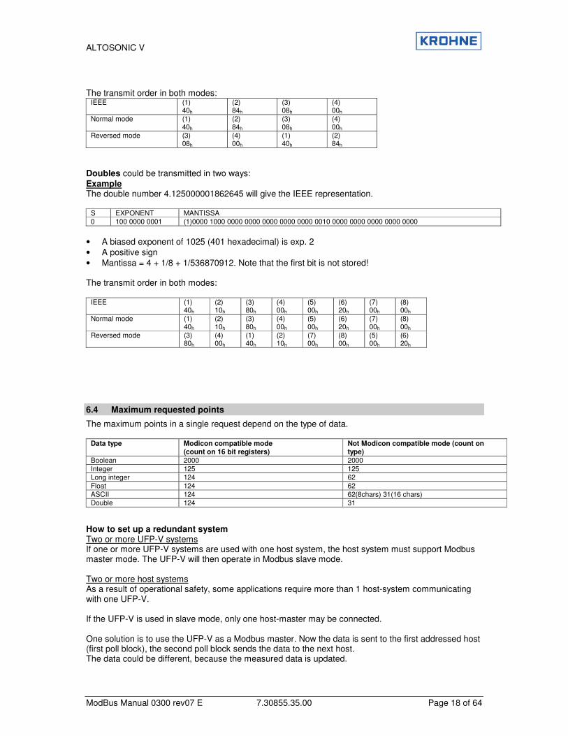
Doubles could be transmitted in two ways: Example The double number 4.125000001862645 will give the IEEE representation.
S EXPONENT MANTISSA 0 100 0000 0001 (1)0000 1000 0000 0000 0000 0000 0000 0010 0000 0000 0000 0000 0000
• A biased exponent of 1025 (401 hexadecimal) is exp. 2 • A positive sign • Mantissa = 4 + 1/8 + 1/536870912. Note that the first bit is not stored! The transmit order in both modes:
IEEE (1) 40h
(2) 10h
(3) 80h
(4) 00h
(5) 00h
(6) 20h
(7) 00h
(8) 00h
Normal mode (1) 40h
(2) 10h
(3) 80h
(4) 00h
(5) 00h
(6) 20h
(7) 00h
(8) 00h
Reversed mode (3) 80h
(4) 00h
(1) 40h
(2) 10h
(7) 00h
(8) 00h
(5) 00h
(6) 20h
6.4 Maximum requested points
The maximum points in a single request depend on the type of data.
Data type Modicon compatible mode (count on 16 bit registers)
Not Modicon compatible mode (count on type)
Boolean 2000 2000 Integer 125 125 Long integer 124 62 Float 124 62 ASCII 124 62(8chars) 31(16 chars) Double 124 31
How to set up a redundant system Two or more UFP-V systems If one or more UFP-V systems are used with one host system, the host system must support Modbus master mode. The UFP-V will then operate in Modbus slave mode. Two or more host systems As a result of operational safety, some applications require more than 1 host-system communicating with one UFP-V. If the UFP-V is used in slave mode, only one host-master may be connected. One solution is to use the UFP-V as a Modbus master. Now the data is sent to the first addressed host (first poll block), the second poll block sends the data to the next host. The data could be different, because the measured data is updated.

ALTOSONIC V
ModBus Manual 0300 rev07 E 7.30855.35.00 Page 19 of 64
Another solution is to send the data to the hosts by means of a broadcast. Now all host systems receive the same data.
ALTOSONIC V
ModBus Manual 0300 rev07 E 7.30855.35.00 Page 20 of 64
7 SET-UP OF THE UFP-V MODBUS DRIVER
7.1 Driver Contents
The driver contains: • Standard Modbus protocol according to Modicon. • Simulation of Modbus Master and Slave mode. • ASCII-mode and RTU mode. • Half and full duplex communication layers supported. • Transmitter ON/OFF level select for half-duplex mode. • Seven or eight data bits, Even/Odd/No parity, 1 or 2 stop bits • Extended data type support. • Function 1, 2, 3, 4, 5, 6, 8,15,16 including exception generation.
7.2 Hardware set-up
To set up the Modbus communication first the hardware should be set-up. The UFP is equipped with a RS485/RS422 Communication Card which provide 2 serial communication channels, the first channel CH1 is used for the communication with the UFC-V, please do not change anything here. The second channel CH2 is free for communication with host systems . There are two generations of RS485 cards: • AX4285A formerly installed • PCL745s currently installed

ALTOSONIC V
ModBus Manual 0300 rev07 E 7.30855.35.00 Page 21 of 64
7.2.1 RS485/422 card: AX4285A
The first generation of RS 485 cards used DIP SWITCH CH1*** : COM 3 Baseaddress ch#1: 3E8 DIP SWITCH CH2*** : COM 4 Baseaddress ch#2: 2E8 JP1*** : COM3 Interrupt IRQ4 JP2*** : COM4 Interrupt IRQ3 JP3*** : COM3 RS 485 mode JP4*** : COM3 Serial resistors enabled, No jumpers installed JP5 : COM4 RS 485 mode as default JP6 : COM4 Serial resistors not enabled, jumpers installed ***(=Krohne Altometer setting) NOTE: RS485 mode and RS422 mode for COM4 (Modbus) differs in set-up by: - Jumper JP5 RS485 or RS422 - The external wiring for RS422 and RS485 External wiring AX5285A for Modbus: The resistors of 120 Ohm must be placed at the Altosonic-V wiring terminal
ALTOSONIC V
ModBus Manual 0300 rev07 E 7.30855.35.00 Page 22 of 64
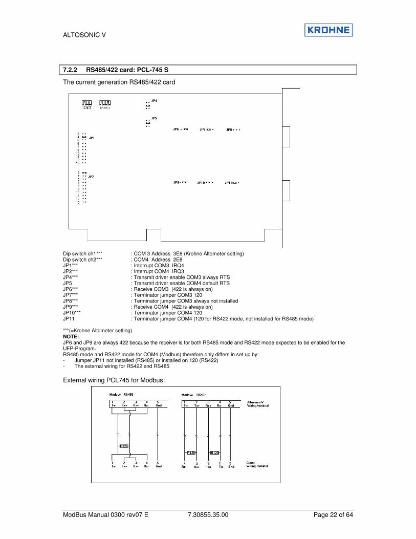
7.2.2 RS485/422 card: PCL-745 S
The current generation RS485/422 card Dip switch ch1*** : COM 3 Address 3E8 (Krohne Altometer setting) Dip switch ch2*** : COM4 Address 2E8 JP1*** : Interrupt COM3 IRQ4 JP2*** : Interrupt COM4 IRQ3 JP4*** : Transmit driver enable COM3 always RTS JP5 : Transmit driver enable COM4 default RTS JP6*** : Receive COM3 (422 is always on) JP7*** : Terminator jumper COM3 120 JP8*** : Terminator jumper COM3 always not installed JP9*** : Receive COM4 (422 is always on) JP10*** : Terminator jumper COM4 120 JP11 : Terminator jumper COM4 (120 for RS422 mode, not installed for RS485 mode) ***(=Krohne Altometer setting) NOTE: JP6 and JP9 are always 422 because the receiver is for both RS485 mode and RS422 mode expected to be enabled for the UFP-Program. RS485 mode and RS422 mode for COM4 (Modbus) therefore only differs in set up by: - Jumper JP11 not installed (RS485) or installed on 120 (RS422) - The external wiring for RS422 and RS485 External wiring PCL745 for Modbus:
ALTOSONIC V
ModBus Manual 0300 rev07 E 7.30855.35.00 Page 23 of 64
7.3 Software set-up
Now set-up the software, all the settings for the Modbus driver is done in the file [coms0300.dat]. See also chapter 9.4 Appendix D: Coms0300.dat file
7.3.1 First set the parameters for the communication line
• 3.1 MODBUS_UART_BASEADRESS for channel 1 is COM4 this is baseaddress 0x2E8 • 3.2 MODBUS_UART_INTERRUPT is for COM4 set to interrupt 3. • Depends on your application : 3.3 MODBUS_UART_BAUDRATE 1200,2400,4800,9600,19200 • 3.4 MODBUS_UART_RTS_MODE to 0. • Depends on your application : 3.5 MODBUS_UART_N_DATABITS to 7 or 8 • Depends on your application : 3.6 MODBUS_UART_N_STOPBITS to 1 or 2 • Depends on your application : 3.7 MODBUS_UART_PARITY to none, even or odd. • Depends on your application : 3.3 MODBUS_UART_BAUDRATE 1200,2400,4800,9600,19200 • Depends on your application :
If you use RS485 set 3.8 MODBUS_UART_HALF_DUPLEX to HALF_DUPLEX(=1) If you use RS422 set 3.8 MODBUS_UART_HALF_DUPLEX to FULL_DUPLEX(=0)
7.3.2 Now select the parameters for the used protocol
• Select the frame type RTU or ASCII with 3.9 MODBUS_TRANSFER_MODE. • Set the UFP-V as MASTER or SLAVE device with 5.1 MODBUS_DEVICE_TYPE. • Select if variables, which are larger than 16 bits are still counted as the number of 16 bit • Set the data points requesting type by parameter 5.2 MODBUS_MODICON_COMPAT:
By type is not modicon compitable ( =0) By 16 bit registers is modicon compitable ( =1)
•
7.3.3 The UFP-V as SLAVE device
The slave mode is activated when the parameter 5.1 MODBUS_DEVICE_TYPE=1. • If the UFP-V acts like a Modbus Slave device, set the SlaveID with 5.3 MODBUS_SLAVE_ID. • The 5.4 FLAG_HOLD_TIME is a hold time on the status flags (Booleans only).
The 5.4 FLAG_HOLD_TIME freezes the flags after the flag has changed from state. Set this time a bit larger than the maximum communication-request interval.
• The next fields define to which Modbus addresses the data of the UFP-V is mapped to, these settings are default settings and should not be changed, only if necessary. The fields are 6 DATAFIELD 1 to N, for every DATAFIELD an access mode could be set. The 6 ACCES MODE defines how the data is send and interpreted when the UFP-V is in slave-mode.
• See the manual of the accompanying byte-order of transmission/reception with the 2 modes.
For Slave-use the driver should be working now.
ALTOSONIC V
ModBus Manual 0300 rev07 E 7.30855.35.00 Page 24 of 64
7.3.4 The UFP-V as Master
The master mode is activated when the parameter 5.1 MODBUS_DEVICE_TYPE=2. For master mode the UFP-V must know what it should send to the connected slave device, therefore the master works with poll blocks. Each poll block defines how a transaction should take place i.e. which slave is addressed, which registers are read or write and how to do it. The maximum number of poll blocks to define is 20. The number of poll blocks to use is set with the parameter 7.1 NUMBER_OF_POLLBLOCKS_TO_USE. During start-up of the UFP-V, a poll block validation check will be done. Only the number of poll blocks defined in 7.1 NUMBER_OF_POLLBLOCKS_TO_USE will be checked. The maximum response time after a poll block request is set by the parameter 7.2 REQUEST_TO_RESPONSE_TIMEOUT. If no response is received from the slave within this time, a poll block timeout error is generated. So for every pollblock (=data movement) set :
• The 7.3a SLAVEID : the address of the slave device , notice that 0 is a broadcast to all slaves, not all the functions are allowed with broadcast messages.
• The 7.3b MASTER REGISTER, this is the location of the data in the UFP-V. • The 7.3c SLAVE REGISTER, this is the location of the data in the slave device. • The 7.3d N_POINTS, this is always the number data points of the specific datatype to transfer, like
1 Boolean, 1 int, 1 float. The real number of 16 bit registers in the Modbus message is calculated. For instance, in modicon compatible mode the number of registers in the message is always 2 times the number of floats. In not-modicon compatible mode the number of registers in the message is always the same as number of floats. So number of points in the pollblock definition always count the datatypes.
• The 7.3e FUNCTION selects which Modbus function is used for the data transfer (see a complete list in the manual).
• The 7.3f DATATYPE is for internal validation only but should be filled in correctly. • The 7.3g DATANOTATION defines in which byte-order the data is send, float, longs, doubles may
be send with different notations (like big and little indian). • The 7.3h DELAY is the time to wait after the last pollblock has been send before sending the next
pollblock. When all the pollblocks are defined, select with 7.1 NUMBER_OF_POLLBLOCKS_TO_USE, which pollblocks to use. 1=first one only, 2 is number one and two …and so on.
ALTOSONIC V
ModBus Manual 0300 rev07 E 7.30855.35.00 Page 25 of 64
7.4 What can go wrong?
When using RS485, check:
• Are the connections between terminal 1 and 4 made? • Are the connections between terminal 2 and 3 made? • Is the terminate resistor placed between 1+4 and 2+3 (only if UFP-V is the end of the line). • Is the jumper set to 485 and not 422? (else the transmitter will continuously be activated and
destroy received messages) • Is the polarity correct? Are the lines by accident swapped? • Is the software set to Half Duplex (3.8 MODBUS_UART_HALF_DUPLEX=1) When using RS422, check:
• Are both terminator resistors placed at the end of the cable on the TX+, TX- and RX+, RX- lines? • Is the jumper on the RS485 card set to 422? • Is the software set to Full duplex ((3.8 MODBUS_UART_HALF_DUPLEX=0)? Other checks:
• Are the following items correct: baud rate (3.3 MODBUS_UART_BAUDRATE) N stop bits (3.6 MODBUS_UART_N_STOPBITS) parity (3.7 MODBUS_UART_PARITY)
• Are both systems in the same mode RTU/ASCII (ASV system = 3.9 MODBUS_TRANSFER_MODE)?
• Is the Slave ID (5.3 MODBUS_SLAVE_ID) correct? • Notice that RTU requires precise timing specifications, some of the RS485 -> RS232/422
converters perform data buffering and may give problems. If this is the problem try the ASCII mode (3.9 MODBUS_TRANSFER_MODE).
• Notice that the Slave device will not give any response when it is addressed with a broadcast (SlaveID=0).
Extra information: The UFP-V has extra windows, which provide information about the Modbus communication: These windows are accessed from the Main Window by function key F10 See also Altosonic-V Operating Manual (chapter RUNTIME WINDOWS)
7.5 How Status Flags are Updated
If the status flags must be self-resetting
Each machine cycle (35 ms) all the error and warning flags are updated with the last machine status. An active flag will be pending for at least (5.4 FLAG_HOLD_TIME * 35) ms. An Active Flag may be reset earlier (by writing a zero) than the pending time (5.4 FLAG_HOLD_TIME * 35 ms), but the next update will be after the pending time. If the flags must be acknowledged To activate this mode, the parameter 5.4 FLAG_HOLD_TIME must be set to 0. Each machine cycle (35 ms) all warning and error flags are updated with the last machine status. The flags can be reset by: • writing a 0 to these flags or • writing a 1 to the accompanying acknowledge flag (each status flag has an accompanying
acknowledge flag) or • writing a 1 to the acknowledge_all flag
(for host computers with limited free programmable Boolean space).
ALTOSONIC V
ModBus Manual 0300 rev07 E 7.30855.35.00 Page 26 of 64
Example of reading a status flag from an UFP-V in slave mode The status flag is read by the master. 1. If the status flag is active,
the master uses this state to perform its actions and sends an acknowledgement to the UFP-V by setting the accompanying ACK_flag to 1. Now the UFP-V updates the status flag with the actual status. Note that in this mode the status flag remains active until the acknowledge is given.
2. If the status flag is not active, the master removes the acknowledge by resetting the ACK_flag.
Example of reading status flag 0 from an UFP-V in master mode 1. The first poll block sends the status flag to the master 2. If the status flag is active, the master uses this status to perform his actions and sends an
acknowledgement to UFP-V by means of setting the accompanying ACK_flag to 1. 3. The next poll block reads this ACK_FLAG and updates it in the UFP-V,
now the UFP-V updates the status flag with the actual status. 3. If the flag is not active, the master removes the acknowledgement by resetting the ACK_flag. As long as the ACK_flag is active the status flag is updated every 35 milliseconds. If the communication speed is known, choose the 5.4 FLAG_HOLD_TIME large enough to give the host the possibility to detect the state of the flags. To set-up a more secure system use the acknowledge method. A disadvantage is the increase in communication time. 5.4 FLAG_HOLD_TIME is located in the coms0300.dat file. See also chapter 9.4 Appendix D: Coms0300.dat file
ALTOSONIC V
ModBus Manual 0300 rev07 E 7.30855.35.00 Page 27 of 64
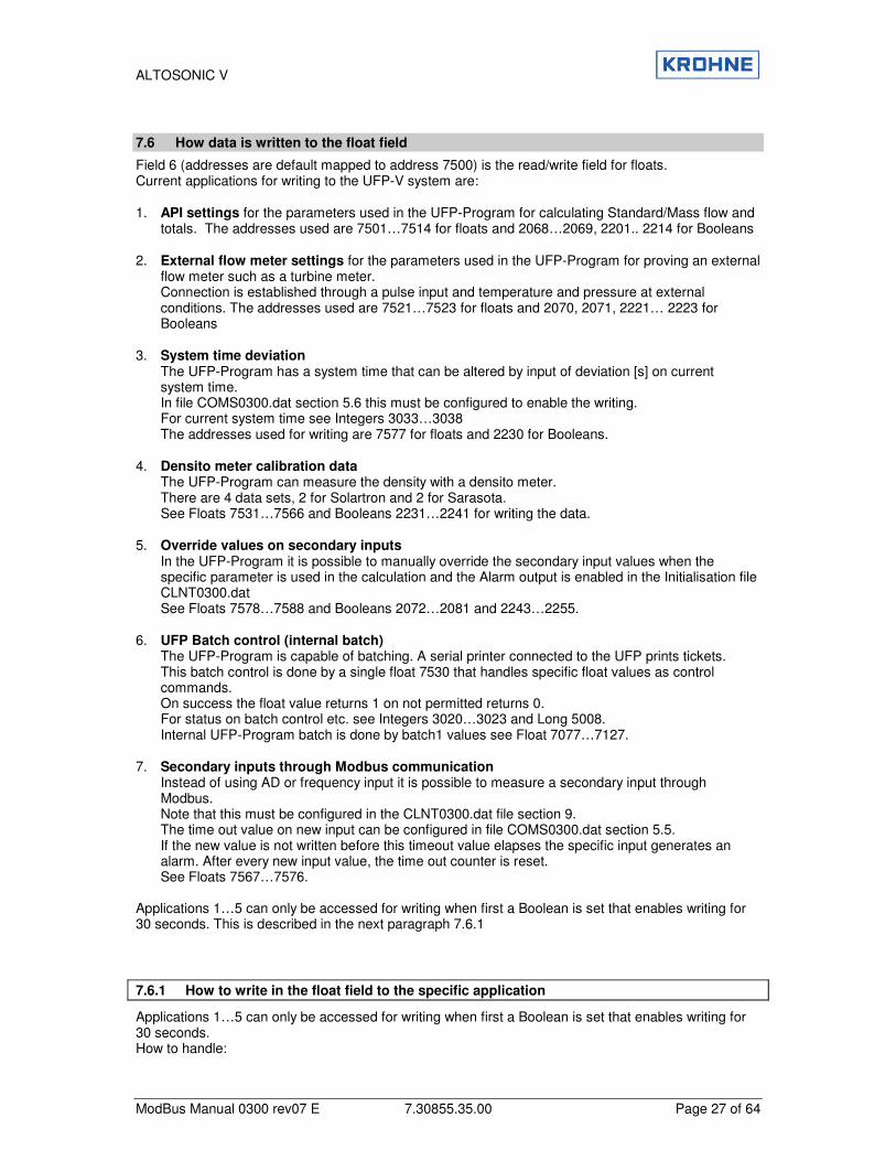
7.6 How data is written to the float field
Field 6 (addresses are default mapped to address 7500) is the read/write field for floats. Current applications for writing to the UFP-V system are: 1. API settings for the parameters used in the UFP-Program for calculating Standard/Mass flow and
totals. The addresses used are 7501…7514 for floats and 2068…2069, 2201.. 2214 for Booleans 2. External flow meter settings for the parameters used in the UFP-Program for proving an external
flow meter such as a turbine meter. Connection is established through a pulse input and temperature and pressure at external conditions. The addresses used are 7521…7523 for floats and 2070, 2071, 2221… 2223 for Booleans
3. System time deviation
The UFP-Program has a system time that can be altered by input of deviation [s] on current system time. In file COMS0300.dat section 5.6 this must be configured to enable the writing. For current system time see Integers 3033…3038 The addresses used for writing are 7577 for floats and 2230 for Booleans.
4. Densito meter calibration data
The UFP-Program can measure the density with a densito meter. There are 4 data sets, 2 for Solartron and 2 for Sarasota. See Floats 7531…7566 and Booleans 2231…2241 for writing the data.
5. Override values on secondary inputs
In the UFP-Program it is possible to manually override the secondary input values when the specific parameter is used in the calculation and the Alarm output is enabled in the Initialisation file CLNT0300.dat See Floats 7578…7588 and Booleans 2072…2081 and 2243…2255.
6. UFP Batch control (internal batch)
The UFP-Program is capable of batching. A serial printer connected to the UFP prints tickets. This batch control is done by a single float 7530 that handles specific float values as control commands. On success the float value returns 1 on not permitted returns 0. For status on batch control etc. see Integers 3020…3023 and Long 5008. Internal UFP-Program batch is done by batch1 values see Float 7077…7127.
7. Secondary inputs through Modbus communication
Instead of using AD or frequency input it is possible to measure a secondary input through Modbus. Note that this must be configured in the CLNT0300.dat file section 9. The time out value on new input can be configured in file COMS0300.dat section 5.5. If the new value is not written before this timeout value elapses the specific input generates an alarm. After every new input value, the time out counter is reset. See Floats 7567…7576.
Applications 1…5 can only be accessed for writing when first a Boolean is set that enables writing for 30 seconds. This is described in the next paragraph 7.6.1
7.6.1 How to write in the float field to the specific application
Applications 1…5 can only be accessed for writing when first a Boolean is set that enables writing for 30 seconds. How to handle:
ALTOSONIC V
ModBus Manual 0300 rev07 E 7.30855.35.00 Page 28 of 64
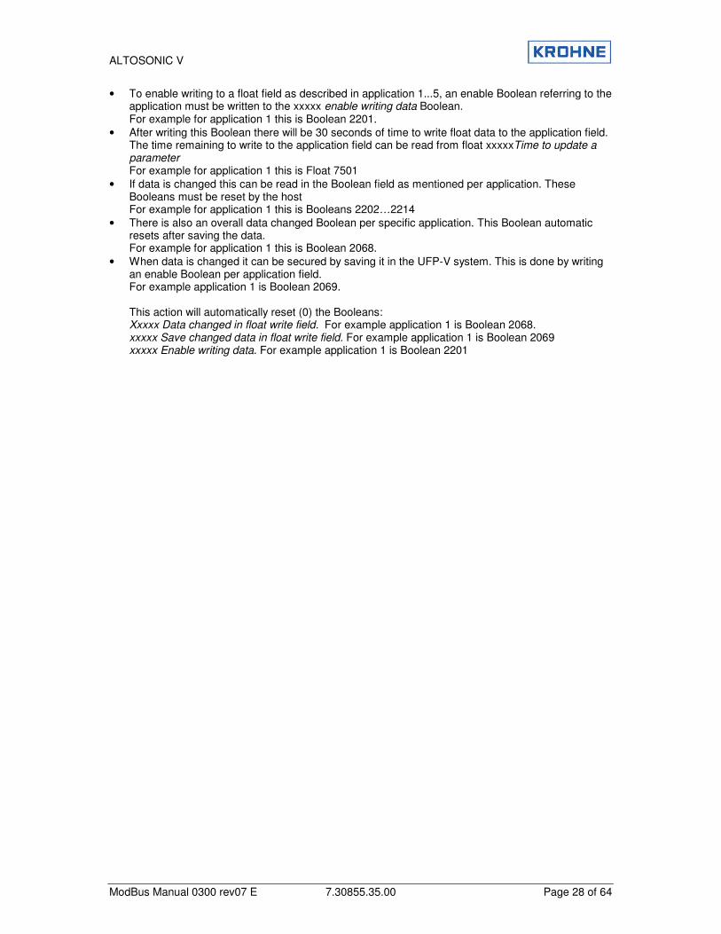
• To enable writing to a float field as described in application 1...5, an enable Boolean referring to the application must be written to the xxxxx enable writing data Boolean. For example for application 1 this is Boolean 2201.
• After writing this Boolean there will be 30 seconds of time to write float data to the application field. The time remaining to write to the application field can be read from float xxxxxTime to update a parameter For example for application 1 this is Float 7501
• If data is changed this can be read in the Boolean field as mentioned per application. These Booleans must be reset by the host For example for application 1 this is Booleans 2202…2214
• There is also an overall data changed Boolean per specific application. This Boolean automatic resets after saving the data. For example for application 1 this is Boolean 2068.
• When data is changed it can be secured by saving it in the UFP-V system. This is done by writing an enable Boolean per application field. For example application 1 is Boolean 2069. This action will automatically reset (0) the Booleans: Xxxxx Data changed in float write field. For example application 1 is Boolean 2068. xxxxx Save changed data in float write field. For example application 1 is Boolean 2069 xxxxx Enable writing data. For example application 1 is Boolean 2201

ALTOSONIC V
ModBus Manual 0300 rev07 E 7.30855.35.00 Page 29 of 64
8 MODBUS MAPPING ASSIGNMENTS The available data is grouped in 9 levels (groups):
1. Gross flow measurement 2. Standard flow measurement 3. Net flow measurement 4. Batching, includes normally the levels 1..3 5. Analysis, diagnostics, quality 6. Control data 7. Used settings (corrections on/of etc) 8. Master meter configuration (direct connection with duty meter) 9. Data measured but not directly used by Altosonic-V, but as an extra service.
8.1 Field 0 (Read only Boolean field)
This data is read only and can be accessed with Modbus function 1 and 2 in Modbus slave mode and with functions 5 and 15 in Modbus master mode. Without further notice 0=non and 1=active
By default the start addresses are mapped to address 1000 (default value)
sta
rt a
dd
ress
Mo
dic
on
Co
mp
No
tMo
dic
on
Co
mp
Typ
e+
Access
Descri
pti
on
Leve
l
Leve
l
Leve
l
Rem
ark
1 B+R Basic flow measurement warning 1 5
2 B+R Basic flow measurement error 1 5
3 B+R System runtime warning 1 5
4 B+R System runtime error 1 5
5 B+R System set-up warning 1 5
6 B+R System set-up error 1 5
7 B+R Totaliser process: sum totalizer rollover occurred 1 5
8 B+R Totaliser process: totalizer reset occurred 1 5
9 B+R Flow direction 1 0=forward 1=reverse
10 B+R Algo. Basic flow on output 1 7
11 B+R Reserved
12 B+R Algo. Reyn. Correction on output. 1 7
13 B+R Swirl correction on output 1 7
14 B+R Temperature correction on output 1 7
15 B+R Standard volume on output 2 7
16 B+R API group out of range 2 5
17 B+R Correction parameters hold. Due to flow deviation 1 5
18 B+R Check Modbus totalisers and batch 1+2 values on hold (see Bool2075) 4
19 B+R Alarm on reading: temperature process 2 5
20 B+R Alarm on reading: pressure process 1 2 5
21 B+R Alarm on reading: densitometer density 2 5
22 B+R Alarm on reading: temperature body 1 5
23 B+R Totaliser standard: sum totaliser rollover occurred 2 5
ALTOSONIC V
ModBus Manual 0300 rev07 E 7.30855.35.00 Page 30 of 64
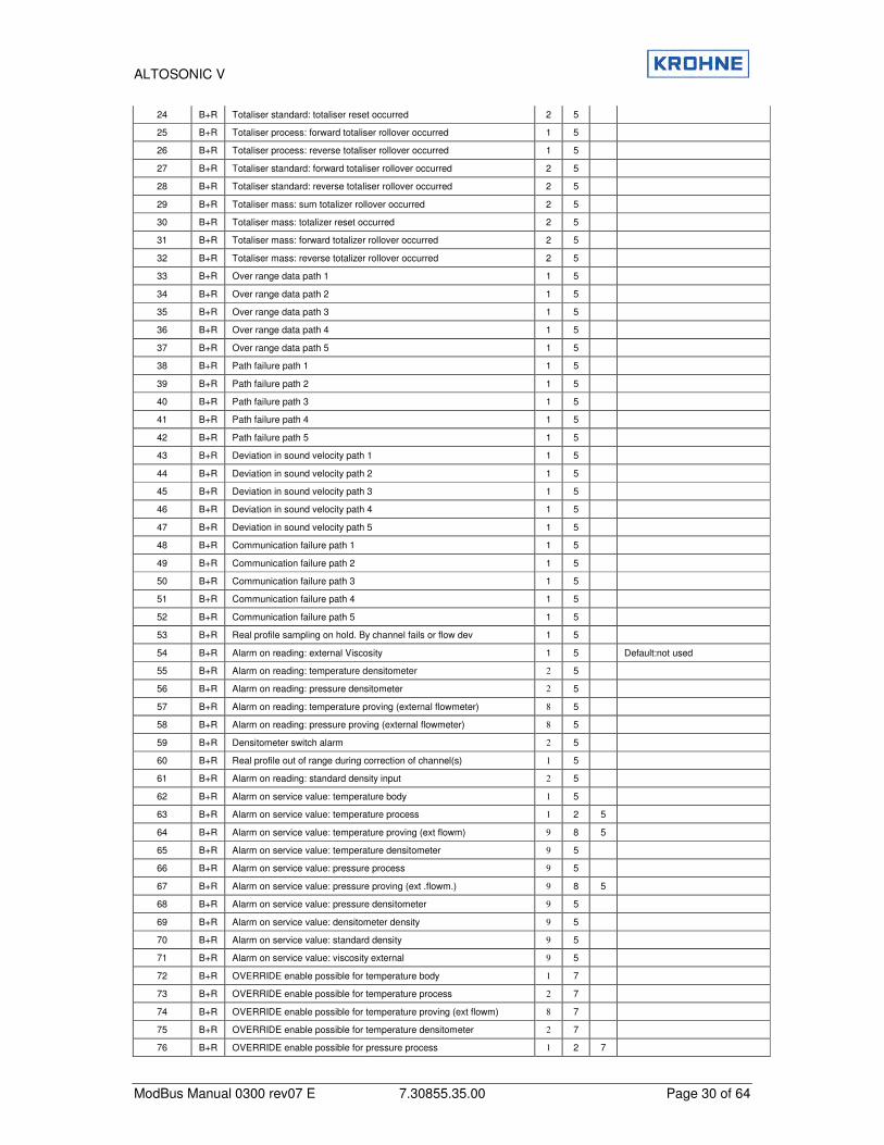
24 B+R Totaliser standard: totaliser reset occurred 2 5
25 B+R Totaliser process: forward totaliser rollover occurred 1 5
26 B+R Totaliser process: reverse totaliser rollover occurred 1 5
27 B+R Totaliser standard: forward totaliser rollover occurred 2 5
28 B+R Totaliser standard: reverse totaliser rollover occurred 2 5
29 B+R Totaliser mass: sum totalizer rollover occurred 2 5
30 B+R Totaliser mass: totalizer reset occurred 2 5
31 B+R Totaliser mass: forward totalizer rollover occurred 2 5
32 B+R Totaliser mass: reverse totalizer rollover occurred 2 5
33 B+R Over range data path 1 1 5
34 B+R Over range data path 2 1 5
35 B+R Over range data path 3 1 5
36 B+R Over range data path 4 1 5
37 B+R Over range data path 5 1 5
38 B+R Path failure path 1 1 5
39 B+R Path failure path 2 1 5
40 B+R Path failure path 3 1 5
41 B+R Path failure path 4 1 5
42 B+R Path failure path 5 1 5
43 B+R Deviation in sound velocity path 1 1 5
44 B+R Deviation in sound velocity path 2 1 5
45 B+R Deviation in sound velocity path 3 1 5
46 B+R Deviation in sound velocity path 4 1 5
47 B+R Deviation in sound velocity path 5 1 5
48 B+R Communication failure path 1 1 5
49 B+R Communication failure path 2 1 5
50 B+R Communication failure path 3 1 5
51 B+R Communication failure path 4 1 5
52 B+R Communication failure path 5 1 5
53 B+R Real profile sampling on hold. By channel fails or flow dev 1 5
54 B+R Alarm on reading: external Viscosity 1 5 Default:not used
55 B+R Alarm on reading: temperature densitometer 2 5
56 B+R Alarm on reading: pressure densitometer 2 5
57 B+R Alarm on reading: temperature proving (external flowmeter) 8 5
58 B+R Alarm on reading: pressure proving (external flowmeter) 8 5
59 B+R Densitometer switch alarm 2 5
60 B+R Real profile out of range during correction of channel(s) 1 5
61 B+R Alarm on reading: standard density input 2 5
62 B+R Alarm on service value: temperature body 1 5
63 B+R Alarm on service value: temperature process 1 2 5
64 B+R Alarm on service value: temperature proving (ext flowm) 9 8 5
65 B+R Alarm on service value: temperature densitometer 9 5
66 B+R Alarm on service value: pressure process 9 5
67 B+R Alarm on service value: pressure proving (ext .flowm.) 9 8 5
68 B+R Alarm on service value: pressure densitometer 9 5
69 B+R Alarm on service value: densitometer density 9 5
70 B+R Alarm on service value: standard density 9 5
71 B+R Alarm on service value: viscosity external 9 5
72 B+R OVERRIDE enable possible for temperature body 1 7
73 B+R OVERRIDE enable possible for temperature process 2 7
74 B+R OVERRIDE enable possible for temperature proving (ext flowm) 8 7
75 B+R OVERRIDE enable possible for temperature densitometer 2 7
76 B+R OVERRIDE enable possible for pressure process 1 2 7
ALTOSONIC V
ModBus Manual 0300 rev07 E 7.30855.35.00 Page 31 of 64
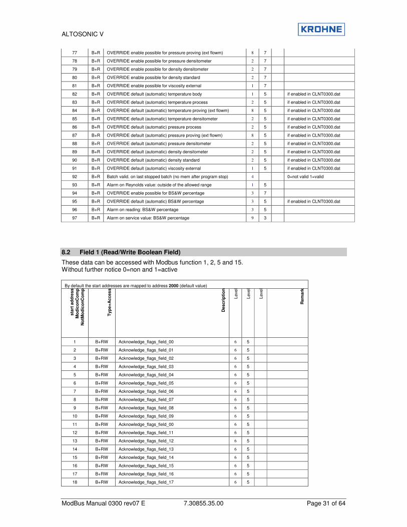
77 B+R OVERRIDE enable possible for pressure proving (ext flowm) 8 7
78 B+R OVERRIDE enable possible for pressure densitometer 2 7
79 B+R OVERRIDE enable possible for density densitometer 2 7
80 B+R OVERRIDE enable possible for density standard 2 7
81 B+R OVERRIDE enable possible for viscosity external 1 7
82 B+R OVERRIDE default (automatic) temperature body 1 5 if enabled in CLNT0300.dat
83 B+R OVERRIDE default (automatic) temperature process 2 5 if enabled in CLNT0300.dat
84 B+R OVERRIDE default (automatic) temperature proving (ext flowm) 8 5 if enabled in CLNT0300.dat
85 B+R OVERRIDE default (automatic) temperature densitometer 2 5 if enabled in CLNT0300.dat
86 B+R OVERRIDE default (automatic) pressure process 2 5 if enabled in CLNT0300.dat
87 B+R OVERRIDE default (automatic) pressure proving (ext flowm) 8 5 if enabled in CLNT0300.dat
88 B+R OVERRIDE default (automatic) pressure densitometer 2 5 if enabled in CLNT0300.dat
89 B+R OVERRIDE default (automatic) density densitometer 2 5 if enabled in CLNT0300.dat
90 B+R OVERRIDE default (automatic) density standard 2 5 if enabled in CLNT0300.dat
91 B+R OVERRIDE default (automatic) viscosity external 1 5 if enabled in CLNT0300.dat
92 B+R Batch valid. on last stopped batch (no mem after program stop) 4 0=not valid 1=valid
93 B+R Alarm on Reynolds value: outside of the allowed range 1 5
94 B+R OVERRIDE enable possible for BS&W percentage 3 7
95 B+R OVERRIDE default (automatic) BS&W percentage 3 5 if enabled in CLNT0300.dat
96 B+R Alarm on reading: BS&W percentage 3 5
97 B+R Alarm on service value: BS&W percentage 9 3
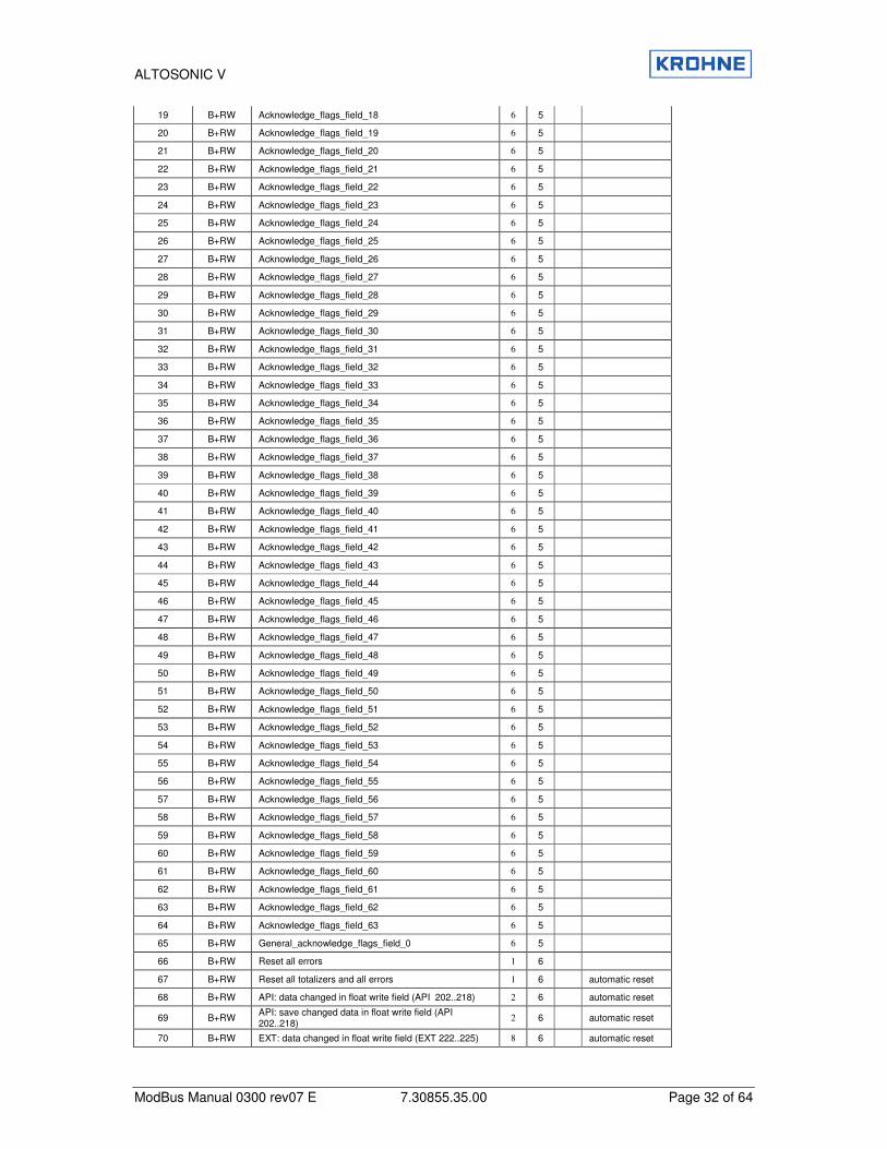
8.2 Field 1 (Read/Write Boolean Field)
These data can be accessed with Modbus function 1, 2, 5 and 15. Without further notice 0=non and 1=active
By default the start addresses are mapped to address 2000 (default value)
sta
rt a
dd
ress
Mo
dic
on
Co
mp
No
tMo
dic
on
Co
mp
Typ
e+
Acces
s
Descri
pti
on
Leve
l
Leve
l
Leve
l
Rem
ark
1 B+RW Acknowledge_flags_field_00 6 5
2 B+RW Acknowledge_flags_field_01 6 5
3 B+RW Acknowledge_flags_field_02 6 5
4 B+RW Acknowledge_flags_field_03 6 5
5 B+RW Acknowledge_flags_field_04 6 5
6 B+RW Acknowledge_flags_field_05 6 5
7 B+RW Acknowledge_flags_field_06 6 5
8 B+RW Acknowledge_flags_field_07 6 5
9 B+RW Acknowledge_flags_field_08 6 5
10 B+RW Acknowledge_flags_field_09 6 5
11 B+RW Acknowledge_flags_field_00 6 5
12 B+RW Acknowledge_flags_field_11 6 5
13 B+RW Acknowledge_flags_field_12 6 5
14 B+RW Acknowledge_flags_field_13 6 5
15 B+RW Acknowledge_flags_field_14 6 5
16 B+RW Acknowledge_flags_field_15 6 5
17 B+RW Acknowledge_flags_field_16 6 5
18 B+RW Acknowledge_flags_field_17 6 5
ALTOSONIC V
ModBus Manual 0300 rev07 E 7.30855.35.00 Page 32 of 64
19 B+RW Acknowledge_flags_field_18 6 5
20 B+RW Acknowledge_flags_field_19 6 5
21 B+RW Acknowledge_flags_field_20 6 5
22 B+RW Acknowledge_flags_field_21 6 5
23 B+RW Acknowledge_flags_field_22 6 5
24 B+RW Acknowledge_flags_field_23 6 5
25 B+RW Acknowledge_flags_field_24 6 5
26 B+RW Acknowledge_flags_field_25 6 5
27 B+RW Acknowledge_flags_field_26 6 5
28 B+RW Acknowledge_flags_field_27 6 5
29 B+RW Acknowledge_flags_field_28 6 5
30 B+RW Acknowledge_flags_field_29 6 5
31 B+RW Acknowledge_flags_field_30 6 5
32 B+RW Acknowledge_flags_field_31 6 5
33 B+RW Acknowledge_flags_field_32 6 5
34 B+RW Acknowledge_flags_field_33 6 5
35 B+RW Acknowledge_flags_field_34 6 5
36 B+RW Acknowledge_flags_field_35 6 5
37 B+RW Acknowledge_flags_field_36 6 5
38 B+RW Acknowledge_flags_field_37 6 5
39 B+RW Acknowledge_flags_field_38 6 5
40 B+RW Acknowledge_flags_field_39 6 5
41 B+RW Acknowledge_flags_field_40 6 5
42 B+RW Acknowledge_flags_field_41 6 5
43 B+RW Acknowledge_flags_field_42 6 5
44 B+RW Acknowledge_flags_field_43 6 5
45 B+RW Acknowledge_flags_field_44 6 5
46 B+RW Acknowledge_flags_field_45 6 5
47 B+RW Acknowledge_flags_field_46 6 5
48 B+RW Acknowledge_flags_field_47 6 5
49 B+RW Acknowledge_flags_field_48 6 5
50 B+RW Acknowledge_flags_field_49 6 5
51 B+RW Acknowledge_flags_field_50 6 5
52 B+RW Acknowledge_flags_field_51 6 5
53 B+RW Acknowledge_flags_field_52 6 5
54 B+RW Acknowledge_flags_field_53 6 5
55 B+RW Acknowledge_flags_field_54 6 5
56 B+RW Acknowledge_flags_field_55 6 5
57 B+RW Acknowledge_flags_field_56 6 5
58 B+RW Acknowledge_flags_field_57 6 5
59 B+RW Acknowledge_flags_field_58 6 5
60 B+RW Acknowledge_flags_field_59 6 5
61 B+RW Acknowledge_flags_field_60 6 5
62 B+RW Acknowledge_flags_field_61 6 5
63 B+RW Acknowledge_flags_field_62 6 5
64 B+RW Acknowledge_flags_field_63 6 5
65 B+RW General_acknowledge_flags_field_0 6 5
66 B+RW Reset all errors 1 6
67 B+RW Reset all totalizers and all errors 1 6 automatic reset
68 B+RW API: data changed in float write field (API 202..218) 2 6 automatic reset
69 B+RW API: save changed data in float write field (API 202..218)
2 6 automatic reset
70 B+RW EXT: data changed in float write field (EXT 222..225) 8 6 automatic reset

ALTOSONIC V
ModBus Manual 0300 rev07 E 7.30855.35.00 Page 33 of 64
71 B+RW EXT: save changed data in float write field (EXT 222..225)
8 6 automatic reset
72 B+RW EXT: restart proving of external flowmeter 8 6 automatic reset
73 B+RW Batch 1 reset averages For Continuous Pipe Line Measurement by host , not for the UFP internal CPL batch mode
4 automatic reset
74 B+RW Batch 2 reset averages For Continuous Pipe Line Measurement by host , not for the UFP internal CPL batch mode
4 6 automatic reset
75 B+RW Modbus output for all totalisers and batch 1+2 values
on hold for 30 sec. (Internally all totalisers continue) 4 6 automatic reset
76 B+RW During batch. Guard Digital contact, CLNT0300.DAT item 20.04 and 20.05,see also Operating manual 10.4.3
4 6 automatic reset
77..200 Reserved
201 B+RW API enable writing data 2 6 reset after 30 sec
202 B+RW API change in: correction type 2 6 manual reset
203 B+RW API change in: density standard type 2 6 manual reset
204 B+RW API change in: fluid type 2 6 manual reset
205 B+RW API change in: stand. density crude (fluid type 0) 2 6 manual reset
206 B+RW API change in: stand. density gasoline (fluid type 1) 2 6 manual reset
207 B+RW API change in: stand. density trans.area (fluid type 2) 2 6 manual reset
208 B+RW API change in: stand. density jet group (fluid type 3) 2 6 manual reset
209 B+RW API change in: stand. density fuel oil (fluid type 4) 2 6 manual reset
210 B+RW API change in: stand. density free fill (fluid type 5) 2 6 manual reset
211 B+RW API change in: free Fill K0 2 6 manual reset
212 B+RW API change in: free Fill K1 2 6 manual reset
213 B+RW API change in: free Fill K2 2 6 manual reset
214 B+RW API change in: temperature standard 2 6 manual reset
215 B+RW Change in: correction standard 2 6 manual reset
216 B+RW Change in: ASTM-IP stand. density 2 6 manual reset
217 B+RW Change in: LPG stand. density 2 6 manual reset
218 B+RW Change in: LPG equilibrium pressure 2 6 manual reset
219..220 Reserved
221 B+RW EXT enable writing data 8 6 automatic reset
222 B+RW EXT change in: K-factor external flowmeter 8 6 manual reset
223 B+RW EXT change in: parameters changeable under flowing conditions or under low flow cuttoff
8 6 manual reset
224 B+RW Change in: MeterFactor (Fwd) 1 6 if enabled in set-up
225 B+RW Change in: MeterFactor (Rev) 1 6 if enabled in set-up
226..229 Reserved
230 B+RW SYSTEM TIME deviation enable writing (see float 7577) 4 6 if enabled in set-up
231 B+RW SOLARTRON1 enable writing data 2 6 automatic reset
232 B+RW SOLARTRON1 change in: calibration data 2 6 automatic reset
233 B+RW SOLARTRON1 save and enable written data 2 6 automatic reset
234 B+RW SOLARTRON2 enable writing data 2 6 automatic reset
235 B+RW SOLARTRON2 change in: calibration data 2 6 automatic reset
236 B+RW SOLARTRON2 save and enable written data 2 6 automatic reset
237 B+RW SARASOTA1 enable writing data 2 6 automatic reset
238 B+RW SARASOTA1 change in: calibration data 2 6 automatic reset
239 B+RW SARASOTA1 save and enable written data 2 6 automatic reset
240 B+RW SARASOTA2 enable writing data 2 6 automatic reset
241 B+RW SARASOTA2 change in: calibration data 2 6 automatic reset
242 B+RW SARASOTA2 save and enable written data 2 6 automatic reset
243 B+RW OVERRIDE: enable writing data 1 2 6 automatic reset 30s
244 B+RW OVERRIDE: change in: OVERRIDE data 1 2 6 automatic reset

ALTOSONIC V
ModBus Manual 0300 rev07 E 7.30855.35.00 Page 34 of 64
245 B+RW OVERRIDE: save and enable written data 1 2 6
246 B+RW OVERRIDE: enable to set value temperature body 1 6 if enable to override
247 B+RW OVERRIDE: enable to set value temperature process 2 6 if enable to override
248 B+RW OVERRIDE: enable to set value temperature proving 8 6 if enable to override
249 B+RW OVERRIDE: enable to set value temperature densitometer
2 6 if enable to override
250 B+RW OVERRIDE: enable to set value pressure process 1 2 6 if enable to override
251 B+RW OVERRIDE: enable to set value pressure proving 8 6 if enable to override
252 B+RW OVERRIDE: enable to set value pressure densitometer to OVERRIDE
2 6 if enable to override
253 B+RW OVERRIDE: enable to set value density densitometer to OVERRIDE
2 6 if enable to override
254 B+RW OVERRIDE: enable to set value density standard to OVERRIDE
2 6 if enable to override
255 B+RW OVERRIDE: enable to set value viscosity to OVERRIDE
2 6 if enable to override
256 B+RW V.O.S. failure alarm (0=OFF.1=ON. if enabled) 1 6 if enabled in setup
257 B+RW V.O.S. failure alarm enable (0=NO.1=YES. if enabled) 1 6 if enabled in setup
258 B+RW BS&W status indication for F7591; 0=ERROR. 1=OK 3 6 if enabled in setup
259 B+RW OVERRIDE enable to set value BS&W percentage to OVERRIDE
3 6 if enabled in setup
Reset totalisers will automatically reset the rollover bits of all totalisers, alarms and process time.
ALTOSONIC V
ModBus Manual 0300 rev07 E 7.30855.35.00 Page 35 of 64
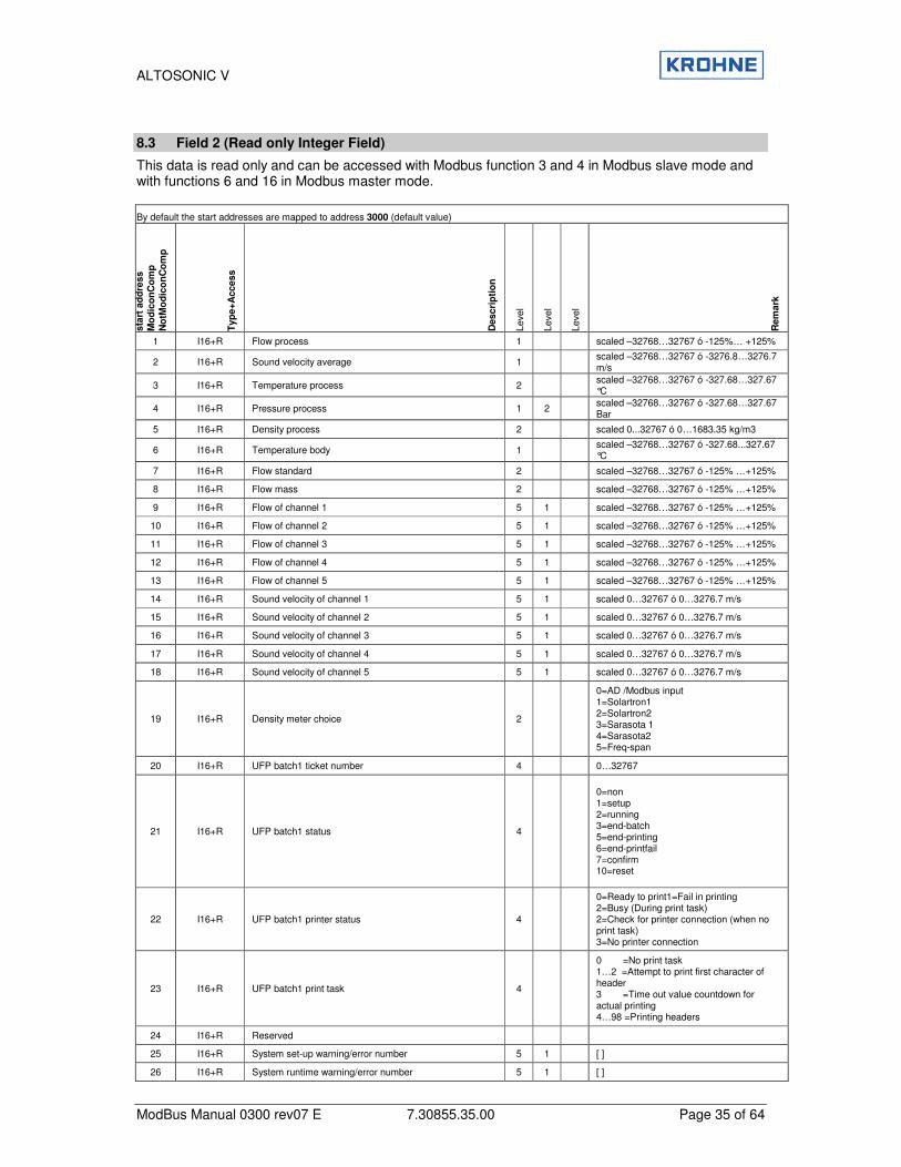
8.3 Field 2 (Read only Integer Field)
This data is read only and can be accessed with Modbus function 3 and 4 in Modbus slave mode and with functions 6 and 16 in Modbus master mode. By default the start addresses are mapped to address 3000 (default value)
sta
rt a
dd
ress
Mo
dic
on
Co
mp
No
tMo
dic
on
Co
mp
Typ
e+
Access
Descri
pti
on
Leve
l
Leve
l
Leve
l
Rem
ark
1 I16+R Flow process 1 scaled –32768…32767 ó -125%… +125%
2 I16+R Sound velocity average 1 scaled –32768…32767 ó -3276.8…3276.7 m/s
3 I16+R Temperature process 2 scaled –32768…32767 ó -327.68…327.67 °C
4 I16+R Pressure process 1 2 scaled –32768…32767 ó -327.68…327.67 Bar
5 I16+R Density process 2 scaled 0...32767 ó 0…1683.35 kg/m3
6 I16+R Temperature body 1 scaled –32768…32767 ó -327.68...327.67 °C
7 I16+R Flow standard 2 scaled –32768…32767 ó -125% …+125%
8 I16+R Flow mass 2 scaled –32768…32767 ó -125% …+125%
9 I16+R Flow of channel 1 5 1 scaled –32768…32767 ó -125% …+125%
10 I16+R Flow of channel 2 5 1 scaled –32768…32767 ó -125% …+125%
11 I16+R Flow of channel 3 5 1 scaled –32768…32767 ó -125% …+125%
12 I16+R Flow of channel 4 5 1 scaled –32768…32767 ó -125% …+125%
13 I16+R Flow of channel 5 5 1 scaled –32768…32767 ó -125% …+125%
14 I16+R Sound velocity of channel 1 5 1 scaled 0…32767 ó 0…3276.7 m/s
15 I16+R Sound velocity of channel 2 5 1 scaled 0…32767 ó 0…3276.7 m/s
16 I16+R Sound velocity of channel 3 5 1 scaled 0…32767 ó 0…3276.7 m/s
17 I16+R Sound velocity of channel 4 5 1 scaled 0…32767 ó 0…3276.7 m/s
18 I16+R Sound velocity of channel 5 5 1 scaled 0…32767 ó 0…3276.7 m/s
19 I16+R Density meter choice 2
0=AD /Modbus input 1=Solartron1 2=Solartron2 3=Sarasota 1 4=Sarasota2 5=Freq-span
20 I16+R UFP batch1 ticket number 4 0…32767
21 I16+R UFP batch1 status 4
0=non 1=setup 2=running 3=end-batch 5=end-printing 6=end-printfail 7=confirm 10=reset
22 I16+R UFP batch1 printer status 4
0=Ready to print1=Fail in printing 2=Busy (During print task) 2=Check for printer connection (when no print task) 3=No printer connection
23 I16+R UFP batch1 print task 4
0 =No print task 1…2 =Attempt to print first character of header 3 =Time out value countdown for actual printing 4…98 =Printing headers
24 I16+R Reserved
25 I16+R System set-up warning/error number 5 1 [ ]
26 I16+R System runtime warning/error number 5 1 [ ]
ALTOSONIC V
ModBus Manual 0300 rev07 E 7.30855.35.00 Page 36 of 64
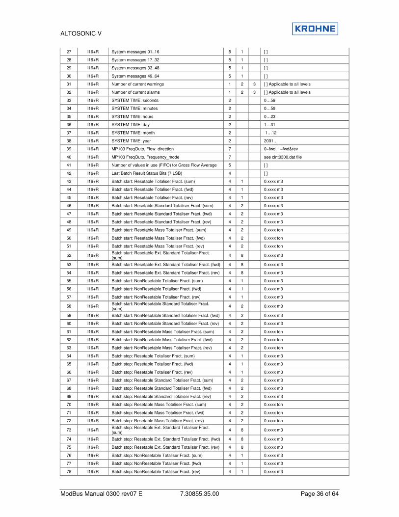
27 I16+R System messages 01..16 5 1 [ ]
28 I16+R System messages 17..32 5 1 [ ]
29 I16+R System messages 33..48 5 1 [ ]
30 I16+R System messages 49..64 5 1 [ ]
31 I16+R Number of current warnings 1 2 3 [ ] Applicable to all levels
32 I16+R Number of current alarms 1 2 3 [ ] Applicable to all levels
33 I16+R SYSTEM TIME: seconds 2 0…59
34 I16+R SYSTEM TIME: minutes 2 0…59
35 I16+R SYSTEM TIME: hours 2 0…23
36 I16+R SYSTEM TIME: day 2 1…31
37 I16+R SYSTEM TIME: month 2 1…12
38 I16+R SYSTEM TIME: year 2 2001…
39 I16+R MP103 FreqOutp. Flow_direction 7 0=fwd, 1=fwd&rev
40 I16+R MP103 FreqOutp. Frequency_mode 7 see clnt0300.dat file
41 I16+R Number of values in use (FIFO) for Gross Flow Average 5 [ ]
42 I16+R Last Batch Result Status Bits (7 LSB) 4 [ ]
43 I16+R Batch start: Resetable Totaliser Fract. (sum) 4 1 0.xxxx m3
44 I16+R Batch start: Resetable Totaliser Fract. (fwd) 4 1 0.xxxx m3
45 I16+R Batch start: Resetable Totaliser Fract. (rev) 4 1 0.xxxx m3
46 I16+R Batch start: Resetable Standard Totaliser Fract. (sum) 4 2 0.xxxx m3
47 I16+R Batch start: Resetable Standard Totaliser Fract. (fwd) 4 2 0.xxxx m3
48 I16+R Batch start: Resetable Standard Totaliser Fract. (rev) 4 2 0.xxxx m3
49 I16+R Batch start: Resetable Mass Totaliser Fract. (sum) 4 2 0.xxxx ton
50 I16+R Batch start: Resetable Mass Totaliser Fract. (fwd) 4 2 0.xxxx ton
51 I16+R Batch start: Resetable Mass Totaliser Fract. (rev) 4 2 0.xxxx ton
52 I16+R Batch start: Resetable Ext. Standard Totaliser Fract. (sum)
4 8 0.xxxx m3
53 I16+R Batch start: Resetable Ext. Standard Totaliser Fract. (fwd) 4 8 0.xxxx m3
54 I16+R Batch start: Resetable Ext. Standard Totaliser Fract. (rev) 4 8 0.xxxx m3
55 I16+R Batch start: NonResetable Totaliser Fract. (sum) 4 1 0.xxxx m3
56 I16+R Batch start: NonResetable Totaliser Fract. (fwd) 4 1 0.xxxx m3
57 I16+R Batch start: NonResetable Totaliser Fract. (rev) 4 1 0.xxxx m3
58 I16+R Batch start: NonResetable Standard Totaliser Fract. (sum)
4 2 0.xxxx m3
59 I16+R Batch start: NonResetable Standard Totaliser Fract. (fwd) 4 2 0.xxxx m3
60 I16+R Batch start: NonResetable Standard Totaliser Fract. (rev) 4 2 0.xxxx m3
61 I16+R Batch start: NonResetable Mass Totaliser Fract. (sum) 4 2 0.xxxx ton
62 I16+R Batch start: NonResetable Mass Totaliser Fract. (fwd) 4 2 0.xxxx ton
63 I16+R Batch start: NonResetable Mass Totaliser Fract. (rev) 4 2 0.xxxx ton
64 I16+R Batch stop: Resetable Totaliser Fract. (sum) 4 1 0.xxxx m3
65 I16+R Batch stop: Resetable Totaliser Fract. (fwd) 4 1 0.xxxx m3
66 I16+R Batch stop: Resetable Totaliser Fract. (rev) 4 1 0.xxxx m3
67 I16+R Batch stop: Resetable Standard Totaliser Fract. (sum) 4 2 0.xxxx m3
68 I16+R Batch stop: Resetable Standard Totaliser Fract. (fwd) 4 2 0.xxxx m3
69 I16+R Batch stop: Resetable Standard Totaliser Fract. (rev) 4 2 0.xxxx m3
70 I16+R Batch stop: Resetable Mass Totaliser Fract. (sum) 4 2 0.xxxx ton
71 I16+R Batch stop: Resetable Mass Totaliser Fract. (fwd) 4 2 0.xxxx ton
72 I16+R Batch stop: Resetable Mass Totaliser Fract. (rev) 4 2 0.xxxx ton
73 I16+R Batch stop: Resetable Ext. Standard Totaliser Fract. (sum)
4 8 0.xxxx m3
74 I16+R Batch stop: Resetable Ext. Standard Totaliser Fract. (fwd) 4 8 0.xxxx m3
75 I16+R Batch stop: Resetable Ext. Standard Totaliser Fract. (rev) 4 8 0.xxxx m3
76 I16+R Batch stop: NonResetable Totaliser Fract. (sum) 4 1 0.xxxx m3
77 I16+R Batch stop: NonResetable Totaliser Fract. (fwd) 4 1 0.xxxx m3
78 I16+R Batch stop: NonResetable Totaliser Fract. (rev) 4 1 0.xxxx m3
ALTOSONIC V
ModBus Manual 0300 rev07 E 7.30855.35.00 Page 37 of 64
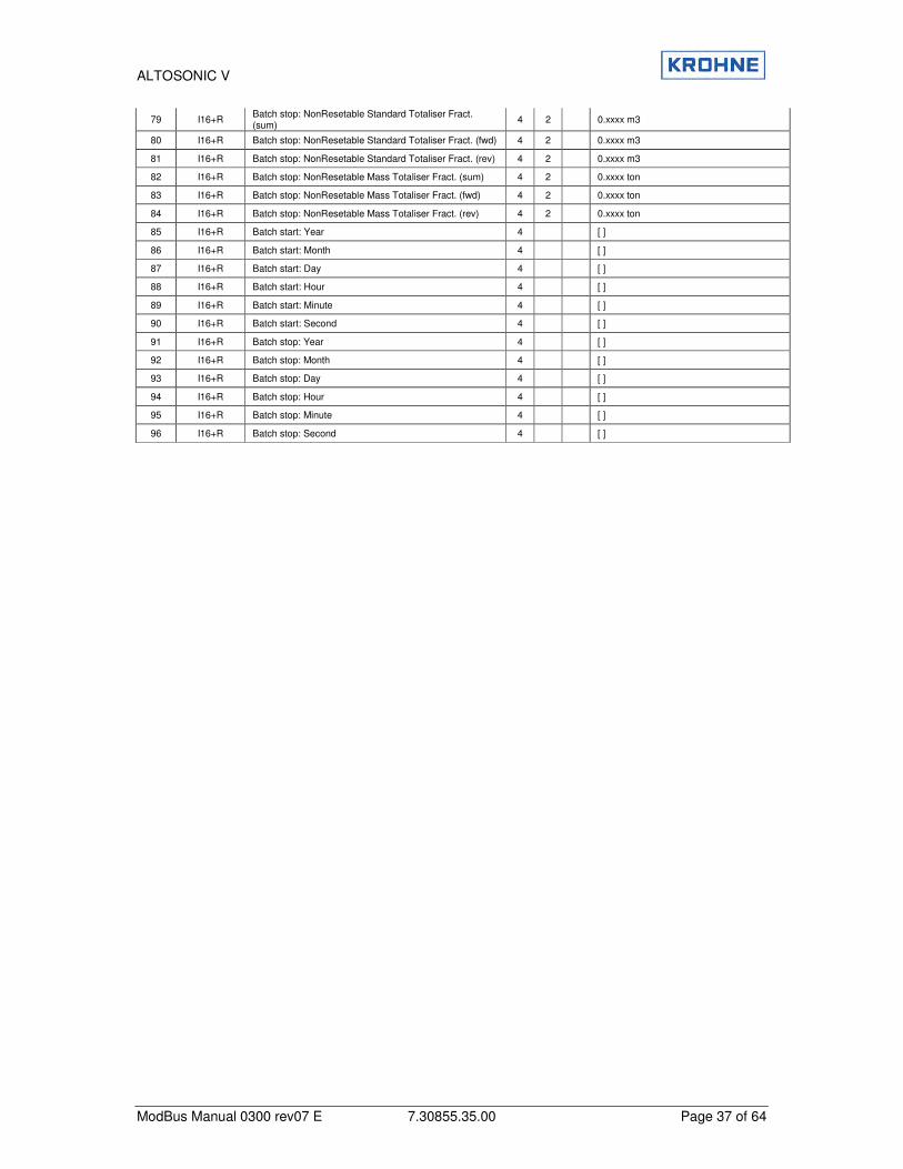
79 I16+R Batch stop: NonResetable Standard Totaliser Fract. (sum)
4 2 0.xxxx m3
80 I16+R Batch stop: NonResetable Standard Totaliser Fract. (fwd) 4 2 0.xxxx m3
81 I16+R Batch stop: NonResetable Standard Totaliser Fract. (rev) 4 2 0.xxxx m3
82 I16+R Batch stop: NonResetable Mass Totaliser Fract. (sum) 4 2 0.xxxx ton
83 I16+R Batch stop: NonResetable Mass Totaliser Fract. (fwd) 4 2 0.xxxx ton
84 I16+R Batch stop: NonResetable Mass Totaliser Fract. (rev) 4 2 0.xxxx ton
85 I16+R Batch start: Year 4 [ ]
86 I16+R Batch start: Month 4 [ ]
87 I16+R Batch start: Day 4 [ ]
88 I16+R Batch start: Hour 4 [ ]
89 I16+R Batch start: Minute 4 [ ]
90 I16+R Batch start: Second 4 [ ]
91 I16+R Batch stop: Year 4 [ ]
92 I16+R Batch stop: Month 4 [ ]
93 I16+R Batch stop: Day 4 [ ]
94 I16+R Batch stop: Hour 4 [ ]
95 I16+R Batch stop: Minute 4 [ ]
96 I16+R Batch stop: Second 4 [ ]

ALTOSONIC V
ModBus Manual 0300 rev07 E 7.30855.35.00 Page 38 of 64
8.4 Field 3 (Read only Long Integer Field)
This data is read only and can be accessed with Modbus function 3 and 4 in Modbus slave mode and with functions 6 and 16 in Modbus master mode.
By default the start addresses are mapped to address 5000 (default value)
sta
rt a
dd
ress
No
tMo
dic
on
Co
mp
sta
rt a
dd
ress
Mo
dic
on
Co
mp
Typ
e+
Ac
cess
Descri
pti
on
Leve
l
Leve
l
Leve
l
Rem
ark
1 1 I32+R Resetable totaliser process sum 1 liter
2 3 I32+R Flow process 1 scaled -32768 ... +32767 ó -125% …+125%
3 5 I32+R Sound velocity average 5 scaled 0…32767 ó 0…3276.7 m/s
4 7 I32+R resetable totaliser standard sum 2 liter
5 9 I32+R Flow standard 2 scaled -32768 … +32767 ó -125%… +125%
6 11 I32+R Resetable totalizer mass sum 2 kg
7 13 I32+R Flow: mass 2 scaled -32768 … +32767 ó -125%… +125%
8 15 I32+R UFP batch1 ticket count 4 0….2147483647
9 17 I32+R Resetable totaliser: process forward 1 liter
10 19 I32+R Resetable totaliser: process reverse 1 liter
11 21 I32+R Resetable totaliser: standard forward 2 liter
12 23 I32+R Resetable totaliser: standard reverse 2 liter
13 25 I32+R Resetable totaliser: mass forward 2 kg
14 27 I32+R Resetable totaliser: mass reverse 2 kg
15 29 I32+R UFP serial number 1 [ ]
16 31 I32+R Software version 1 [ ]
17 33 I32+R System set-up warning/error number 1 [ ]
18 35 I32+R System runtime warning/error number 1 [ ]
19 37 I32+R System messages 01...32 1 [ ]
20 39 I32+R System messages 33...64 1 [ ]
21 41 I32+R Resetable totaliser: external flowmeter actual total 8 liter
22 43 I32+R Resetable totaliser: external flowmeter standard total 8 liter
23 45 I32+R Resetable totaliser: external flowmeter mass total 8 kg
24 47 I32+R Process time (resets on totaliser reset) 5 s, used as watch dog for host
25 49 I32+R Non resetable totaliser: process sum 1 0.1m3
26 51 I32+R Non resetable totaliser: process forward 1 0.1m3
27 53 I32+R Non resetable totaliser: process reverse 1 0.1m3
28 55 I32+R Non resetable totaliser: standard sum 2 0.1m3
29 57 I32+R Non resetable totaliser: standard forward 2 0.1m3
30 59 I32+R Non resetable totaliser: standard reverse 2 0.1m3
31 61 I32+R Non resetable totaliser: mass sum 2 0.1 ton
32 63 I32+R Non resetable totaliser: mass forward 2 0.1 ton
33 65 I32+R Non resetable totaliser: mass reverse 2 0.1 ton
34 67 I32+R Resetable totaliser: process sum (nett.oil) 3 liter
35 69 I32+R Resetable totaliser: process forward (nett.oil) 3 liter
36 71 I32+R Resetable totaliser: process reverse (nett.oil) 3 liter
37 73 I32+R Resetable totaliser: standard sum (nett.oil) 3 liter
38 75 I32+R Resetable totaliser: standard forward (nett.oil) 3 liter
39 77 I32+R Resetable totaliser: standard reverse (nett.oil) 3 liter
40 79 I32+R Resetable totaliser: mass sum (nett.oil) 3 kg
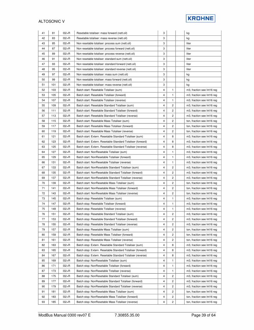
ALTOSONIC V
ModBus Manual 0300 rev07 E 7.30855.35.00 Page 39 of 64
41 81 I32+R Resetable totaliser: mass forward (nett.oil) 3 kg
42 83 I32+R Resetable totaliser: mass reverse (nett.oil) 3 kg
43 85 I32+R Non resetable totaliser: process sum (nett.oil) 3 liter
44 87 I32+R Non resetable totaliser: process forward (nett.oil) 3 liter
45 89 I32+R Non resetable totaliser: process reverse (nett.oil) 3 liter
46 91 I32+R Non resetable totaliser: standard sum (nett.oil) 3 liter
47 93 I32+R Non resetable totaliser: standard forward (nett.oil) 3 liter
48 95 I32+R Non resetable totaliser: standard reverse (nett.oil) 3 liter
49 97 I32+R Non resetable totaliser: mass sum (nett.oil) 3 kg
50 99 I32+R Non resetable totaliser: mass forward (nett.oil) 3 kg
51 101 I32+R Non resetable totaliser: mass reverse (nett.oil) 3 kg
52 103 I32+R Batch start: Resetable Totaliser (sum) 4 1 m3, fraction see Int16 reg
53 105 I32+R Batch start: Resetable Totaliser (forward) 4 1 m3, fraction see Int16 reg
54 107 I32+R Batch start: Resetable Totaliser (reverse) 4 1 m3, fraction see Int16 reg
55 109 I32+R Batch start: Resetable Standard Totaliser (sum) 4 2 m3, fraction see Int16 reg
56 111 I32+R Batch start: Resetable Standard Totaliser (forward) 4 2 m3, fraction see Int16 reg
57 113 I32+R Batch start: Resetable Standard Totaliser (reverse) 4 2 m3, fraction see Int16 reg
58 115 I32+R Batch start: Resetable Mass Totaliser (sum) 4 2 ton, fraction see Int16 reg
59 117 I32+R Batch start: Resetable Mass Totaliser (forward) 4 2 ton, fraction see Int16 reg
60 119 I32+R Batch start: Resetable Mass Totaliser (reverse) 4 2 ton, fraction see Int16 reg
61 121 I32+R Batch start: Extern. Resetable Standard Totaliser (sum) 4 8 m3, fraction see Int16 reg
62 123 I32+R Batch start: Extern. Resetable Standard Totaliser (forward) 4 8 m3, fraction see Int16 reg
63 125 I32+R Batch start: Extern. Resetable Standard Totaliser (reverse) 4 8 m3, fraction see Int16 reg
64 127 I32+R Batch start: NonResetable Totaliser (sum) 4 1 m3, fraction see Int16 reg
65 129 I32+R Batch start: NonResetable Totaliser (forward) 4 1 m3, fraction see Int16 reg
66 131 I32+R Batch start: NonResetable Totaliser (reverse) 4 1 m3, fraction see Int16 reg
67 133 I32+R Batch start: NonResetable Standard Totaliser (sum) 4 2 m3, fraction see Int16 reg
68 135 I32+R Batch start: NonResetable Standard Totaliser (forward) 4 2 m3, fraction see Int16 reg
69 137 I32+R Batch start: NonResetable Standard Totaliser (reverse) 4 2 m3, fraction see Int16 reg
70 139 I32+R Batch start: NonResetable Mass Totaliser (sum) 4 2 ton, fraction see Int16 reg
71 141 I32+R Batch start: NonResetable Mass Totaliser (forward) 4 2 ton, fraction see Int16 reg
72 143 I32+R Batch start: NonResetable Mass Totaliser (reverse) 4 2 ton, fraction see Int16 reg
73 145 I32+R Batch stop: Resetable Totaliser (sum) 4 1 m3, fraction see Int16 reg
74 147 I32+R Batch stop: Resetable Totaliser (forward) 4 1 m3, fraction see Int16 reg
75 149 I32+R Batch stop: Resetable Totaliser (reverse) 4 1 m3, fraction see Int16 reg
76 151 I32+R Batch stop: Resetable Standard Totaliser (sum) 4 2 m3, fraction see Int16 reg
77 153 I32+R Batch stop: Resetable Standard Totaliser (forward) 4 2 m3, fraction see Int16 reg
78 155 I32+R Batch stop: Resetable Standard Totaliser (reverse) 4 2 m3, fraction see Int16 reg
79 157 I32+R Batch stop: Resetable Mass Totaliser (sum) 4 2 ton, fraction see Int16 reg
80 159 I32+R Batch stop: Resetable Mass Totaliser (forward) 4 2 ton, fraction see Int16 reg
81 161 I32+R Batch stop: Resetable Mass Totaliser (reverse) 4 2 ton, fraction see Int16 reg
82 163 I32+R Batch stop: Extern. Resetable Standard Totaliser (sum) 4 8 m3, fraction see Int16 reg
83 165 I32+R Batch stop: Extern. Resetable Standard Totaliser (forward) 4 8 m3, fraction see Int16 reg
84 167 I32+R Batch stop: Extern. Resetable Standard Totaliser (reverse) 4 8 m3, fraction see Int16 reg
85 169 I32+R Batch stop: NonResetable Totaliser (sum) 4 1 m3, fraction see Int16 reg
86 171 I32+R Batch stop: NonResetable Totaliser (forward) 4 1 m3, fraction see Int16 reg
87 173 I32+R Batch stop: NonResetable Totaliser (reverse) 4 1 m3, fraction see Int16 reg
88 175 I32+R Batch stop: NonResetable Standard Totaliser (sum) 4 2 m3, fraction see Int16 reg
89 177 I32+R Batch stop: NonResetable Standard Totaliser (forward) 4 2 m3, fraction see Int16 reg
90 179 I32+R Batch stop: NonResetable Standard Totaliser (reverse) 4 2 m3, fraction see Int16 reg
91 181 I32+R Batch stop: NonResetable Mass Totaliser (sum) 4 2 ton, fraction see Int16 reg
92 183 I32+R Batch stop: NonResetable Mass Totaliser (forward) 4 2 ton, fraction see Int16 reg
93 185 I32+R Batch stop: NonResetable Mass Totaliser (reverse) 4 2 ton, fraction see Int16 reg
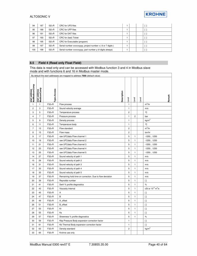
ALTOSONIC V
ModBus Manual 0300 rev07 E 7.30855.35.00 Page 40 of 64
94 187 I32+R CRC for UFS files 1 [ ]
95 189 I32+R CRC for UFP files 1 [ ]
96 191 I32+R CRC for DAT files 1 [ ]
97 193 I32+R CRC for (last) Ticket 1 [ ]
98 195 I32+R CRC for Executable (program) 1 [ ]
99 197 I32+R Serial number xxxxxxyyyy, project number x ( 6 or 7 digits ) 1 [ ]
100 199 I32+R Serial number xxxxxxyyyy, part number y (4 digits always) 1 [ ]
8.5 Field 4 (Read only Float Field)
This data is read only and can be accessed with Modbus function 3 and 4 in Modbus slave mode and with functions 6 and 16 in Modbus master mode.
By default the start addresses are mapped to address 7000 (default value)
sta
rt a
dd
ress
No
tMo
dic
on
Co
mp
sta
rt a
dd
ress
Mo
dic
on
Co
mp
Typ
e+
Access
Descri
pti
on
Leve
l
Leve
l
Leve
l
Rem
ark
1 1 F32+R Flow process 1 m3/hr
2 3 F32+R Sound velocity average 1 m/s
3 5 F32+R Temperature process 2 °C
4 7 F32+R Pressure process 1 2 bar
5 9 F32+R Density process 1 kg/m3
6 11 F32+R Temperature body 1 °C
7 13 F32+R Flow standard 2 m3/hr
8 15 F32+R Flow mass 2 ton/hr
9 17 F32+R raw UFCdata Flow channel 1 5 1 -1250…1250
10 19 F32+R raw UFCdata Flow channel 2 5 1 -1250…1250
11 21 F32+R raw UFCdata Flow channel 3 5 1 -1250…1250
12 23 F32+R raw UFCdata Flow channel 4 5 1 -1250…1250
13 25 F32+R raw UFCdata Flow channel 5 5 1 -1250…1250
14 27 F32+R Sound velocity of path 1 5 1 m/s
15 29 F32+R Sound velocity of path 2 5 1 m/s
16 31 F32+R Sound velocity of path 3 5 1 m/s
17 33 F32+R Sound velocity of path 4 5 1 m/s
18 35 F32+R Sound velocity of path 5 5 1 m/s
19 37 F32+R Remaining hold time on correction. Due to flow deviation 5 1 m/s
20 39 F32+R Reynolds number 5 1 [ ]
21 41 F32+R Swirl % profile diagnostics 5 1 %
22 43 F32+R Viscosity internal 5 1 cSt or 10-6 m2/s
23 45 F32+R A 5 1 [ ]
24 47 F32+R B 5 1 [ ]
25 49 F32+R A_offset 5 1 [ ]
26 51 F32+R B_offset 5 1 [ ]
27 53 F32+R Kr 5 1 [ ]
28 55 F32+R Ks 5 1 [ ]
29 57 F32+R Skewness % profile diagnostics 5 1 %
30 59 F32+R Kbp Pressure Body expansion correction factor 1 [ ]
31 61 F32+R Kb Thermal Body expansion correction factor 1 [ ]
32 63 F32+R Density standard 2 kg/m3
33 65 F32+R Krohne use only
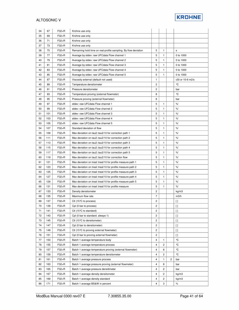
ALTOSONIC V
ModBus Manual 0300 rev07 E 7.30855.35.00 Page 41 of 64
34 67 F32+R Krohne use only
35 69 F32+R Krohne use only
36 71 F32+R Krohne use only
37 73 F32+R Krohne use only
38 75 F32+R Remaining hold time on real-profile sampling. By flow deviation 5 1 s
39 77 F32+R Average by stdev: raw UFCdata Flow channel 1 5 1 0 to 1000
40 79 F32+R Average by stdev: raw UFCdata Flow channel 2 5 1 0 to 1000
41 81 F32+R Average by stdev: raw UFCdata Flow channel 3 5 1 0 to 1000
42 83 F32+R Average by stdev: raw UFCdata Flow channel 4 5 1 0 to 1000
43 85 F32+R Average by stdev: raw UFCdata Flow channel 5 5 1 0 to 1000
44 87 F32+R Viscosity external (default not used) 1 cSt or 10-6 m2/s
45 89 F32+R Temperature densitometer 2 °C
46 91 F32+R Pressure densitometer 2 bar
47 93 F32+R Temperature proving (external flowmeter) 8 °C
48 95 F32+R Pressure proving (external flowmeter) 8 bar
49 97 F32+R stdev: raw UFCdata Flow channel 1 5 1 %'
50 99 F32+R stdev: raw UFCdata Flow channel 2 5 1 %'
51 101 F32+R stdev: raw UFCdata Flow channel 3 5 1 %'
52 103 F32+R stdev: raw UFCdata Flow channel 4 5 1 %'
53 105 F32+R stdev: raw UFCdata Flow channel 5 5 1 %'
54 107 F32+R Standard deviation of flow 5 1 %'
55 109 F32+R Max deviation on tau2::tau2/10 for correction path 1 5 1 %'
56 111 F32+R Max deviation on tau2::tau2/10 for correction path 2 5 1 %'
57 113 F32+R Max deviation on tau2::tau2/10 for correction path 3 5 1 %'
58 115 F32+R Max deviation on tau2::tau2/10 for correction path 4 5 1 %'
59 117 F32+R Max deviation on tau2::tau2/10 for correction path 5 5 1 %'
60 119 F32+R Max deviation on tau2::tau2/10 for correction flow 5 1 %'
61 121 F32+R Max deviation on treal::treal/10 for profile measure path 1 5 1 %'
62 123 F32+R Max deviation on treal::treal/10 for profile measure path 2 5 1 %'
63 125 F32+R Max deviation on treal::treal/10 for profile measure path 3 5 1 %'
64 127 F32+R Max deviation on treal::treal/10 for profile measure path 4 5 1 %'
65 129 F32+R Max deviation on treal::treal/10 for profile measure path 5 5 1 %'
66 131 F32+R Max deviation on treal::treal/10 for profile measure 5 1 %'
67 133 F32+R Density densitometer 2 kg/m3
68 135 F32+R Maximum flow rate 7 m3/h
69 137 F32+R Ctl (15°C to process) 2 [ ]
70 139 F32+R Cpl (0 bar to process) 2 [ ]
71 141 F32+R Ctl (15°C to standard) 2 [ ]
72 143 F32+R Cpl (0 bar to standard. always 1) 2 [ ]
73 145 F32+R Ctl (15°C to densitometer) 2 [ ]
74 147 F32+R Cpl (0 bar to densitometer) 2 [ ]
75 149 F32+R Ctl (15°C to proving external flowmeter) 2 [ ]
76 151 F32+R Cpl (0 bar to proving external flowmeter) 2 [ ]
77 153 F32+R Batch 1 average temperature body 4 1 °C
78 155 F32+R Batch 1 average temperature process 4 2 °C
79 157 F32+R Batch 1 average temperature proving (external flowmeter) 4 8 °C
80 159 F32+R Batch 1 average temperature densitometer 4 2 °C
81 161 F32+R Batch 1 average pressure process 4 1 2 bar
82 163 F32+R Batch 1 average pressure proving (external flowmeter) 4 8 bar
83 165 F32+R Batch 1 average pressure densitimeter 4 2 bar
84 167 F32+R Batch 1 average density densitometer 4 2 kg/m3
85 169 F32+R Batch 1 average density standard 4 2 kg/m3
86 171 F32+R Batch 1 avarage BS&W in percent 4 3 %

ALTOSONIC V
ModBus Manual 0300 rev07 E 7.30855.35.00 Page 42 of 64
87 173 F32+R Batch 1 average Ctl (15°C to process) 4 2 [ ]
88 175 F32+R Batch 1 average Cpl (0 bar to process) 4 2 [ ]
89 177 F32+R Batch 1 average Ctl (15°C to standard) 4 2 [ ]
90 179 F32+R Batch 1 average Cpl (0 bar to standard. always 1) 4 2 [ ]
91 181 F32+R Batch 1 average Ctl (15°C to densitometer) 4 2 [ ]
92 183 F32+R Batch 1 average Cpl (0 bar to densitometer) 4 2 [ ]
93 185 F32+R Batch 1 average Ctl (15°C to proving external flowmeter) 4 8 2 [ ]
94 187 F32+R Batch 1 average Cpl (0 bar to proving external flowmeter) 4 8 2 [ ]
95 189 F32+R Batch 1 average temperature standard 4 2 °C
96 191 F32+R Batch 1 average density process 4 2 kg/m3
97 193 F32+R Batch 1 average flow proces 4 1 m3/h
98 195 F32+R Batch 1 average density proving external flowmeter 4 8 kg/m3
99 197 F32+R Batch 1 average flow proving external flowmeter 4 8 m3/h
100 199 F32+R Batch 1 average Installed Kfactor proving (external flowmeter) 4 8 puls/liter
101 201 F32+R Batch 1 found new Kfactor proving (external flowmeter) 4 8 puls/liter
102 203 F32+R Batch 1 difference installed vs new found Kfactor (external flow 4 8 %
103 205 F32+R Batch 1 alarm: General flow 1-4 channels down 4 1 5 s
104 207 F32+R Batch 1 alarm: General flow all channels down 4 1 5 s
105 209 F32+R Batch 1 alarm: calculation API group mismatch 4 2 5 s
106 211 F32+R Batch 1 alarm: system runtime alarm occured 4 1 5 s
107 213 F32+R Batch 1 alarm: real time profile out of range when used 4 1 5 s
108 215 F32+R Batch 1 alarm: measurement out of range temperature body 4 1 5 s
109 217 F32+R Batch 1 alarm: measurement out of range temperature process 4 2 5 s
110 219 F32+R Batch 1 alarm: measurement out of range temperature proving 4 8 5 s
111 221 F32+R Batch 1 alarm: measurement out of range temperature densitometer 4 2 5 s
112 223 F32+R Batch 1 alarm: measurement out of range pressure process 4 1 2 s
113 225 F32+R Batch 1 alarm: measurement out of range pressure proving (ext flow) 4 8 5 s
114 227 F32+R Batch 1 alarm: measurement out of range pressure densitometer 4 2 5 s
115 229 F32+R Batch 1 alarm: measurement out of range density densitometer 4 2 5 s
116 231 F32+R Batch 1 alarm: measurement out of range density standard 4 2 5 s
117 233 F32+R Batch 1 alarm: measurement out of range viscosity external 4 1 5 s
118 235 F32+R Batch 1 alarm: OVERRIDE applied temperature body 4 1 5 s
119 237 F32+R Batch 1 alarm: OVERRIDE applied temperature process 4 2 5 s
120 239 F32+R Batch 1 alarm: OVERRIDE applied temperature proving (ext flowmeter)
4 8 5 s
121 241 F32+R Batch 1 alarm: OVERRIDE applied temperature densitometer 4 2 5 s
122 243 F32+R Batch 1 alarm: OVERRIDE applied pressure process 4 1 2 s
123 245 F32+R Batch 1 alarm: OVERRIDE applied pressure proving (ext flowmeter) 4 8 5 s
124 247 F32+R Batch 1 alarm: OVERRIDE applied pressure densitometer 4 2 5 s
125 249 F32+R Batch 1 alarm: OVERRIDE applied density densitometer 4 2 5 s
126 251 F32+R Batch 1 alarm: OVERRIDE applied density standard 4 2 5 s
127 253 F32+R Batch 1 alarm: OVERRIDE applied viscosity external 4 1 5 s
128 255 F32+R Batch 2 average temperature body 4 1 °C
129 257 F32+R Batch 2 average temperature process 4 2 °C
130 259 F32+R Batch 2 average temperature proving (external flowmeter) 4 8 2 °C
131 261 F32+R Batch 2 average temperature densitometer 4 2 °C
132 263 F32+R Batch 2 average pressure process 4 1 2 bar
133 265 F32+R Batch 2 average pressure proving (external flowmeter) 4 8 2 bar
134 267 F32+R Batch 2 average pressure densitometer 4 2 bar
135 269 F32+R Batch 2 average density densitometer 4 2 kg/m3
136 271 F32+R Batch 2 average density standard 4 2 kg/m3
137 273 F32+R Batch 2 avarage BS&W in percent 4 3 cSt or 10-6 m2/s
138 275 F32+R Batch 2 average Ctl (15°C to process) 4 2 [ ]
139 277 F32+R Batch 2 average Cpl (0 bar to process) 4 2 [ ]
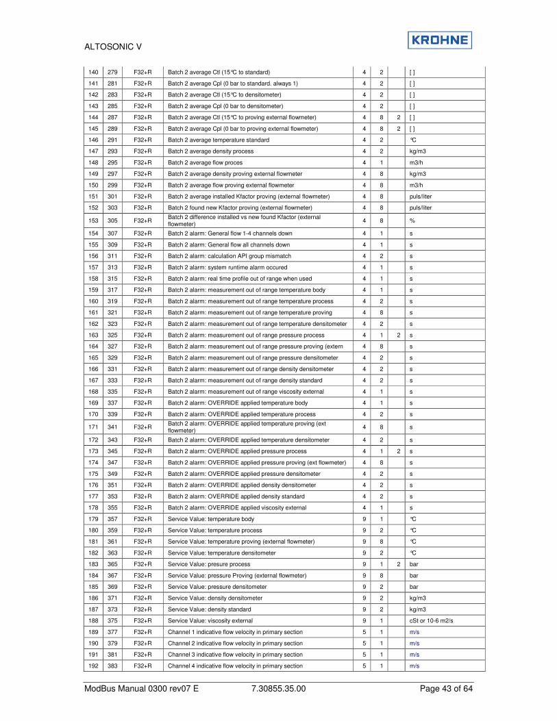
ALTOSONIC V
ModBus Manual 0300 rev07 E 7.30855.35.00 Page 43 of 64
140 279 F32+R Batch 2 average Ctl (15°C to standard) 4 2 [ ]
141 281 F32+R Batch 2 average Cpl (0 bar to standard. always 1) 4 2 [ ]
142 283 F32+R Batch 2 average Ctl (15°C to densitometer) 4 2 [ ]
143 285 F32+R Batch 2 average Cpl (0 bar to densitometer) 4 2 [ ]
144 287 F32+R Batch 2 average Ctl (15°C to proving external flowmeter) 4 8 2 [ ]
145 289 F32+R Batch 2 average Cpl (0 bar to proving external flowmeter) 4 8 2 [ ]
146 291 F32+R Batch 2 average temperature standard 4 2 °C
147 293 F32+R Batch 2 average density process 4 2 kg/m3
148 295 F32+R Batch 2 average flow proces 4 1 m3/h
149 297 F32+R Batch 2 average density proving external flowmeter 4 8 kg/m3
150 299 F32+R Batch 2 average flow proving external flowmeter 4 8 m3/h
151 301 F32+R Batch 2 average installed Kfactor proving (external flowmeter) 4 8 puls/liter
152 303 F32+R Batch 2 found new Kfactor proving (external flowmeter) 4 8 puls/liter
153 305 F32+R Batch 2 difference installed vs new found Kfactor (external flowmeter)
4 8 %
154 307 F32+R Batch 2 alarm: General flow 1-4 channels down 4 1 s
155 309 F32+R Batch 2 alarm: General flow all channels down 4 1 s
156 311 F32+R Batch 2 alarm: calculation API group mismatch 4 2 s
157 313 F32+R Batch 2 alarm: system runtime alarm occured 4 1 s
158 315 F32+R Batch 2 alarm: real time profile out of range when used 4 1 s
159 317 F32+R Batch 2 alarm: measurement out of range temperature body 4 1 s
160 319 F32+R Batch 2 alarm: measurement out of range temperature process 4 2 s
161 321 F32+R Batch 2 alarm: measurement out of range temperature proving 4 8 s
162 323 F32+R Batch 2 alarm: measurement out of range temperature densitometer 4 2 s
163 325 F32+R Batch 2 alarm: measurement out of range pressure process 4 1 2 s
164 327 F32+R Batch 2 alarm: measurement out of range pressure proving (extern 4 8 s
165 329 F32+R Batch 2 alarm: measurement out of range pressure densitometer 4 2 s
166 331 F32+R Batch 2 alarm: measurement out of range density densitometer 4 2 s
167 333 F32+R Batch 2 alarm: measurement out of range density standard 4 2 s
168 335 F32+R Batch 2 alarm: measurement out of range viscosity external 4 1 s
169 337 F32+R Batch 2 alarm: OVERRIDE applied temperature body 4 1 s
170 339 F32+R Batch 2 alarm: OVERRIDE applied temperature process 4 2 s
171 341 F32+R Batch 2 alarm: OVERRIDE applied temperature proving (ext flowmeter)
4 8 s
172 343 F32+R Batch 2 alarm: OVERRIDE applied temperature densitometer 4 2 s
173 345 F32+R Batch 2 alarm: OVERRIDE applied pressure process 4 1 2 s
174 347 F32+R Batch 2 alarm: OVERRIDE applied pressure proving (ext flowmeter) 4 8 s
175 349 F32+R Batch 2 alarm: OVERRIDE applied pressure densitometer 4 2 s
176 351 F32+R Batch 2 alarm: OVERRIDE applied density densitometer 4 2 s
177 353 F32+R Batch 2 alarm: OVERRIDE applied density standard 4 2 s
178 355 F32+R Batch 2 alarm: OVERRIDE applied viscosity external 4 1 s
179 357 F32+R Service Value: temperature body 9 1 °C
180 359 F32+R Service Value: temperature process 9 2 °C
181 361 F32+R Service Value: temperature proving (external flowmeter) 9 8 °C
182 363 F32+R Service Value: temperature densitometer 9 2 °C
183 365 F32+R Service Value: presure process 9 1 2 bar
184 367 F32+R Service Value: pressure Proving (external flowmeter) 9 8 bar
185 369 F32+R Service Value: pressure densitometer 9 2 bar
186 371 F32+R Service Value: density densitometer 9 2 kg/m3
187 373 F32+R Service Value: density standard 9 2 kg/m3
188 375 F32+R Service Value: viscosity external 9 1 cSt or 10-6 m2/s
189 377 F32+R Channel 1 indicative flow velocity in primary section 5 1 m/s
190 379 F32+R Channel 2 indicative flow velocity in primary section 5 1 m/s
191 381 F32+R Channel 3 indicative flow velocity in primary section 5 1 m/s
192 383 F32+R Channel 4 indicative flow velocity in primary section 5 1 m/s
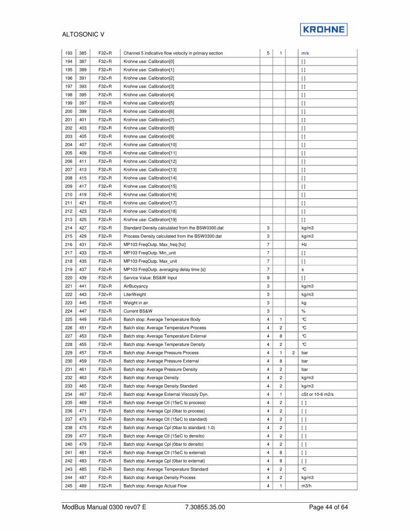
ALTOSONIC V
ModBus Manual 0300 rev07 E 7.30855.35.00 Page 44 of 64
193 385 F32+R Channel 5 indicative flow velocity in primary section 5 1 m/s
194 387 F32+R Krohne use: Calibration[0] [ ]
195 389 F32+R Krohne use: Calibration[1] [ ]
196 391 F32+R Krohne use: Calibration[2] [ ]
197 393 F32+R Krohne use: Calibration[3] [ ]
198 395 F32+R Krohne use: Calibration[4] [ ]
199 397 F32+R Krohne use: Calibration[5] [ ]
200 399 F32+R Krohne use: Calibration[6] [ ]
201 401 F32+R Krohne use: Calibration[7] [ ]
202 403 F32+R Krohne use: Calibration[8] [ ]
203 405 F32+R Krohne use: Calibration[9] [ ]
204 407 F32+R Krohne use: Calibration[10] [ ]
205 409 F32+R Krohne use: Calibration[11] [ ]
206 411 F32+R Krohne use: Calibration[12] [ ]
207 413 F32+R Krohne use: Calibration[13] [ ]
208 415 F32+R Krohne use: Calibration[14] [ ]
209 417 F32+R Krohne use: Calibration[15] [ ]
210 419 F32+R Krohne use: Calibration[16] [ ]
211 421 F32+R Krohne use: Calibration[17] [ ]
212 423 F32+R Krohne use: Calibration[18] [ ]
213 425 F32+R Krohne use: Calibration[19] [ ]
214 427 F32+R Standard Density calculated from the BSW0300.dat 3 kg/m3
215 429 F32+R Process Density calculated from the BSW0300.dat 3 kg/m3
216 431 F32+R MP103 FreqOutp. Max_freq [hz] 7 Hz
217 433 F32+R MP103 FreqOutp. Min_unit 7 [ ]
218 435 F32+R MP103 FreqOutp. Max_unit 7 [ ]
219 437 F32+R MP103 FreqOutp. averaging delay time [s] 7 s
220 439 F32+R Service Value: BS&W Input 9 [ ]
221 441 F32+R AirBuoyancy 3 kg/m3
222 443 F32+R LiterWeight 3 kg/m3
223 445 F32+R Weight in air 3 kg
224 447 F32+R Current BS&W 3 %
225 449 F32+R Batch stop: Average Temperature Body 4 1 °C
226 451 F32+R Batch stop: Average Temperature Process 4 2 °C
227 453 F32+R Batch stop: Average Temperature External 4 8 °C
228 455 F32+R Batch stop: Average Temperature Density 4 2 °C
229 457 F32+R Batch stop: Average Pressure Process 4 1 2 bar
230 459 F32+R Batch stop: Average Pressure External 4 8 bar
231 461 F32+R Batch stop: Average Pressure Density 4 2 bar
232 463 F32+R Batch stop: Average Density 4 2 kg/m3
233 465 F32+R Batch stop: Average Density Standard 4 2 kg/m3
234 467 F32+R Batch stop: Average External Viscosity Dyn. 4 1 cSt or 10-6 m2/s
235 469 F32+R Batch stop: Average Ctl (15øC to process) 4 2 [ ]
236 471 F32+R Batch stop: Average Cpl (0bar to process) 4 2 [ ]
237 473 F32+R Batch stop: Average Ctl (15øC to standard) 4 2 [ ]
238 475 F32+R Batch stop: Average Cpl (0bar to standard: 1.0) 4 2 [ ]
239 477 F32+R Batch stop: Average Ctl (15øC to densito) 4 2 [ ]
240 479 F32+R Batch stop: Average Cpl (0bar to densito) 4 2 [ ]
241 481 F32+R Batch stop: Average Ctl (15øC to external) 4 8 [ ]
242 483 F32+R Batch stop: Average Cpl (0bar to external) 4 8 [ ]
243 485 F32+R Batch stop: Average Temperature Standard 4 2 °C
244 487 F32+R Batch stop: Average Density Process 4 2 kg/m3
245 489 F32+R Batch stop: Average Actual Flow 4 1 m3/h
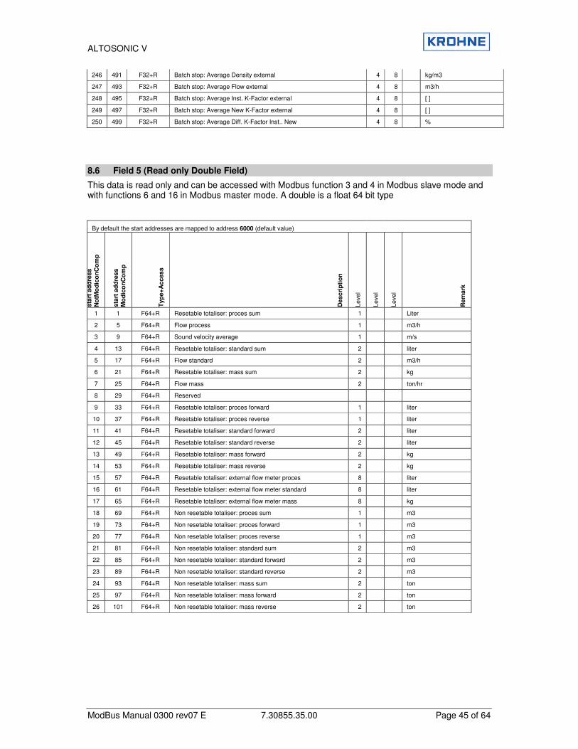
ALTOSONIC V
ModBus Manual 0300 rev07 E 7.30855.35.00 Page 45 of 64
246 491 F32+R Batch stop: Average Density external 4 8 kg/m3
247 493 F32+R Batch stop: Average Flow external 4 8 m3/h
248 495 F32+R Batch stop: Average Inst. K-Factor external 4 8 [ ]
249 497 F32+R Batch stop: Average New K-Factor external 4 8 [ ]
250 499 F32+R Batch stop: Average Diff. K-Factor Inst.. New 4 8 %
8.6 Field 5 (Read only Double Field)
This data is read only and can be accessed with Modbus function 3 and 4 in Modbus slave mode and with functions 6 and 16 in Modbus master mode. A double is a float 64 bit type
By default the start addresses are mapped to address 6000 (default value)
sta
rt a
dd
ress
No
tMo
dic
on
Co
mp
sta
rt a
dd
ress
Mo
dic
on
Co
mp
Typ
e+
Acces
s
Desc
rip
tio
n
Leve
l
Leve
l
Leve
l
Rem
ark
1 1 F64+R Resetable totaliser: proces sum 1 Liter
2 5 F64+R Flow process 1 m3/h
3 9 F64+R Sound velocity average 1 m/s
4 13 F64+R Resetable totaliser: standard sum 2 liter
5 17 F64+R Flow standard 2 m3/h
6 21 F64+R Resetable totaliser: mass sum 2 kg
7 25 F64+R Flow mass 2 ton/hr
8 29 F64+R Reserved
9 33 F64+R Resetable totaliser: proces forward 1 liter
10 37 F64+R Resetable totaliser: proces reverse 1 liter
11 41 F64+R Resetable totaliser: standard forward 2 liter
12 45 F64+R Resetable totaliser: standard reverse 2 liter
13 49 F64+R Resetable totaliser: mass forward 2 kg
14 53 F64+R Resetable totaliser: mass reverse 2 kg
15 57 F64+R Resetable totaliser: external flow meter proces 8 liter
16 61 F64+R Resetable totaliser: external flow meter standard 8 liter
17 65 F64+R Resetable totaliser: external flow meter mass 8 kg
18 69 F64+R Non resetable totaliser: proces sum 1 m3
19 73 F64+R Non resetable totaliser: proces forward 1 m3
20 77 F64+R Non resetable totaliser: proces reverse 1 m3
21 81 F64+R Non resetable totaliser: standard sum 2 m3
22 85 F64+R Non resetable totaliser: standard forward 2 m3
23 89 F64+R Non resetable totaliser: standard reverse 2 m3
24 93 F64+R Non resetable totaliser: mass sum 2 ton
25 97 F64+R Non resetable totaliser: mass forward 2 ton
26 101 F64+R Non resetable totaliser: mass reverse 2 ton
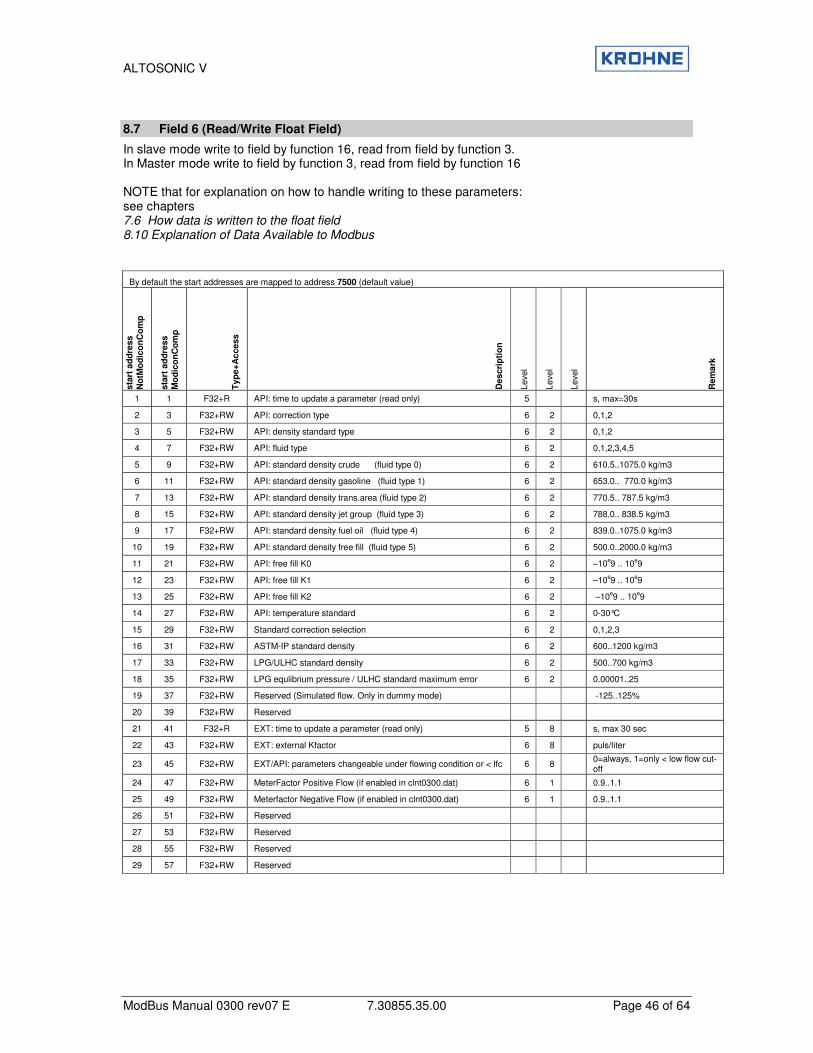
ALTOSONIC V
ModBus Manual 0300 rev07 E 7.30855.35.00 Page 46 of 64
8.7 Field 6 (Read/Write Float Field)
In slave mode write to field by function 16, read from field by function 3. In Master mode write to field by function 3, read from field by function 16 NOTE that for explanation on how to handle writing to these parameters: see chapters 7.6 How data is written to the float field 8.10 Explanation of Data Available to Modbus
By default the start addresses are mapped to address 7500 (default value)
sta
rt a
dd
ress
No
tMo
dic
on
Co
mp
sta
rt a
dd
ress
Mo
dic
on
Co
mp
Typ
e+
Ac
cess
Descri
pti
on
Leve
l
Leve
l
Leve
l
Rem
ark
1 1 F32+R API: time to update a parameter (read only) 5 s, max=30s
2 3 F32+RW API: correction type 6 2 0,1,2
3 5 F32+RW API: density standard type 6 2 0,1,2
4 7 F32+RW API: fluid type 6 2 0,1,2,3,4,5
5 9 F32+RW API: standard density crude (fluid type 0) 6 2 610.5..1075.0 kg/m3
6 11 F32+RW API: standard density gasoline (fluid type 1) 6 2 653.0.. 770.0 kg/m3
7 13 F32+RW API: standard density trans.area (fluid type 2) 6 2 770.5.. 787.5 kg/m3
8 15 F32+RW API: standard density jet group (fluid type 3) 6 2 788.0.. 838.5 kg/m3
9 17 F32+RW API: standard density fuel oil (fluid type 4) 6 2 839.0..1075.0 kg/m3
10 19 F32+RW API: standard density free fill (fluid type 5) 6 2 500.0..2000.0 kg/m3
11 21 F32+RW API: free fill K0 6 2 –10e9 .. 10e9
12 23 F32+RW API: free fill K1 6 2 –10e9 .. 10e9
13 25 F32+RW API: free fill K2 6 2 –10e9 .. 10e9
14 27 F32+RW API: temperature standard 6 2 0-30°C
15 29 F32+RW Standard correction selection 6 2 0,1,2,3
16 31 F32+RW ASTM-IP standard density 6 2 600..1200 kg/m3
17 33 F32+RW LPG/ULHC standard density 6 2 500..700 kg/m3
18 35 F32+RW LPG equlibrium pressure / ULHC standard maximum error 6 2 0.00001..25
19 37 F32+RW Reserved (Simulated flow. Only in dummy mode) -125..125%
20 39 F32+RW Reserved
21 41 F32+R EXT: time to update a parameter (read only) 5 8 s, max 30 sec
22 43 F32+RW EXT: external Kfactor 6 8 puls/liter
23 45 F32+RW EXT/API: parameters changeable under flowing condition or < lfc 6 8 0=always, 1=only < low flow cut-off
24 47 F32+RW MeterFactor Positive Flow (if enabled in clnt0300.dat) 6 1 0.9..1.1
25 49 F32+RW Meterfactor Negative Flow (if enabled in clnt0300.dat) 6 1 0.9..1.1
26 51 F32+RW Reserved
27 53 F32+RW Reserved
28 55 F32+RW Reserved
29 57 F32+RW Reserved
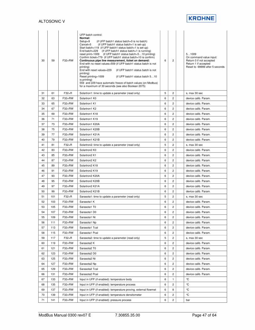
ALTOSONIC V
ModBus Manual 0300 rev07 E 7.30855.35.00 Page 47 of 64
30 59 F32+RW
UFP batch control: Normal: Setup=9 (if UFP batch1 status batch=0 is no batch) Cancel=5 (if UFP batch1 status batch=1 is set-up) Start batch=119 (if UFP batch1 status batch=1 is set-up) End batch=229 (if UFP batch1 status batch=1 is running) reset print=1009 (if UFP batch1 status batch=5…10 printing) Confirm ticket=779 (if UFP batch1 status batch=10 is confirm) Continuous pipe line measurement, ticket on demand: End with no reset values=559 (if UFP batch1 status batch is not printing) End with reset values=229 (if UFP batch1 status batch is not printing) Reset printing=1009 (if UFP batch1 status batch 5…10 is printing) 559 and 229 have automatic freeze of batch values (on Modbus) for a maximum of 30 seconds (see also Boolean 2075)
6 2
5…1009 On command value input: Return 0 if not accepted Return 1 if accepted Reset to -99999 after 5 seconds
31 61 F32+R Solartron1: time to update a parameter (read only) 5 2 s, max 30 sec
32 63 F32+RW Solartron1 K0 6 2 device calib. Param.
33 65 F32+RW Solartron1 K1 6 2 device calib. Param.
34 67 F32+RW Solartron1 K2 6 2 device calib. Param.
35 69 F32+RW Solartron1 K18 6 2 device calib. Param.
36 71 F32+RW Solartron1 K19 6 2 device calib. Param.
37 73 F32+RW Solartron1 K20A 6 2 device calib. Param.
38 75 F32+RW Solartron1 K20B 6 2 device calib. Param.
39 77 F32+RW Solartron1 K21A 6 2 device calib. Param.
40 79 F32+RW Solartron1 K21B 6 2 device calib. Param.
41 81 F32+R Solartron2: time to update a parameter (read only) 5 2 s, max 30 sec
42 83 F32+RW Solartron2 K0 6 2 device calib. Param.
43 85 F32+RW Solartron2 K1 6 2 device calib. Param.
44 87 F32+RW Solartron2 K2 6 2 device calib. Param.
45 89 F32+RW Solartron2 K18 6 2 device calib. Param.
46 91 F32+RW Solartron2 K19 6 2 device calib. Param.
47 93 F32+RW Solartron2 K20A 6 2 device calib. Param.
48 95 F32+RW Solartron2 K20B 6 2 device calib. Param.
49 97 F32+RW Solartron2 K21A 6 2 device calib. Param.
50 99 F32+RW Solartron2 K21B 6 2 device calib. Param.
51 101 F32+R Sarasota1: time to update a parameter (read only) 5 2 s, max 30 sec
52 103 F32+RW Sarasota1 K 6 2 device calib. Param.
53 105 F32+RW Sarasota1 T0 6 2 device calib. Param.
54 107 F32+RW Sarasota1 D0 6 2 device calib. Param.
55 109 F32+RW Sarasota1 Nt 6 2 device calib. Param.
56 111 F32+RW Sarasota1 Np 6 2 device calib. Param.
57 113 F32+RW Sarasota1 Tcal 6 2 device calib. Param.
58 115 F32+RW Sarasota1 Pcal 6 2 device calib. Param.
59 117 F32+R Sarasota2: time to update a parameter (read only) 5 2 s, max 30 sec
60 119 F32+RW Sarasota2 K 6 2 device calib. Param.
61 121 F32+RW Sarasota2 T0 6 2 device calib. Param.
62 123 F32+RW Sarasota2 D0 6 2 device calib. Param.
63 125 F32+RW Sarasota2 Nt 6 2 device calib. Param.
64 127 F32+RW Sarasota2 Np 6 2 device calib. Param.
65 129 F32+RW Sarasota2 Tcal 6 2 device calib. Param.
66 131 F32+RW Sarasota2 Pcal 6 2 device calib. Param.
67 133 F32+RW Input in UFP (if enabled): temperature body 6 1 °C
68 135 F32+RW Input in UFP (if enabled): temperature process 6 2 °C
69 137 F32+RW Input in UFP (if enabled): temperature proving. external flowmet 6 8 °C
70 139 F32+RW Input in UFP (if enabled): temperature densitometer 6 2 °C
71 141 F32+RW Input in UFP (if enabled): pressure process 6 2 bar
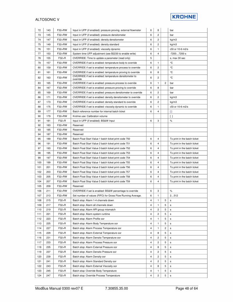
ALTOSONIC V
ModBus Manual 0300 rev07 E 7.30855.35.00 Page 48 of 64
72 143 F32+RW Input in UFP (if enabled): pressure proving. external flowmeter 6 8 bar
73 145 F32+RW Input in UFP (if enabled): pressure densitometer 6 2 bar
74 147 F32+RW Input in UFP (if enabled): density densitometer 6 2 kg/m3
75 149 F32+RW Input in UFP (if enabled): density standard 6 2 kg/m3
76 151 F32+RW Input in UFP (if enabled): viscosity dynamic 6 1 cSt or 10-6 m2/s
77 153 F32+RW System time UFP adjustment (see B2230 to enable write) 6 4 -7200…7200 s
78 155 F32+R OVERRIDE: Time to update a parameter (read only) 5 s, max 30 sec
79 157 F32+RW OVERRIDE if set is enabled: temperature body to override 6 1 °C
80 159 F32+RW OVERRIDE if set is enabled: temperature process to override 6 2 °C
81 161 F32+RW OVERRIDE if set is enabled: temperature proving to override 6 8 °C
82 163 F32+RW OVERRIDE if set is enabled: temperature densitometer to override
6 2 °C
83 165 F32+RW OVERRIDE if set is enabled: pressure process to override 6 1 2 bar
84 167 F32+RW OVERRIDE if set is enabled: pressure proving to override 6 8 bar
85 169 F32+RW OVERRIDE if set is enabled: pressure densitometer to override 6 2 bar
86 171 F32+RW OVERRIDE if set is enabled: density densitometer to override 6 2 kg/m3
87 173 F32+RW OVERRIDE if set is enabled: density standard to override 6 2 kg/m3
88 175 F32+RW OVERRIDE if set is enabled: viscosity dynamic to override 6 1 cSt or 10-6 m2/s
89 177 F32+RW Batch reference number for internal batch ticket 6 4 [ ]
90 179 F32+RW Krohne use: Calibration volume [ ]
91 181 F32+R Input in UFP (if enabled): BS&W Input 6 3 %
92 183 F32+RW Reserved
93 185 F32+RW Reserved
94 187 F32+RW Reserved
95 189 F32+RW Batch Float Start Value 1 batch ticket print code 750 6 4 To print in the batch ticket
96 191 F32+RW Batch Float Start Value 2 batch ticket print code 751 6 4 To print in the batch ticket
97 193 F32+RW Batch Float Start Value 3 batch ticket print code 752 6 4 To print in the batch ticket
98 195 F32+RW Batch Float Start Value 4 batch ticket print code 753 6 4 To print in the batch ticket
99 197 F32+RW Batch Float Start Value 5 batch ticket print code 754 6 4 To print in the batch ticket
100 199 F32+RW Batch Float Stop Value 1 batch ticket print code 755 6 4 To print in the batch ticket
101 201 F32+RW Batch Float Stop Value 2 batch ticket print code 756 6 4 To print in the batch ticket
102 203 F32+RW Batch Float Stop Value 3 batch ticket print code 757 6 4 To print in the batch ticket
103 205 F32+RW Batch Float Stop Value 4 batch ticket print code 758 6 4 To print in the batch ticket
104 207 F32+RW Batch Float Stop Value 5 batch ticket print code 759 6 4 To print in the batch ticket
105 209 F32+RW Reserved
106 211 F32+RW OVERRIDE if set is enabled: BS&W percentage to override 6 3 %
107 213 F32+RW Set number of values (FIFO) for Gross Flow Running Average. 6 1 2…512
108 215 F32+R Batch stop: Alarm 1-4 channels down 4 1 5 s
109 217 F32+R Batch stop: Alarm all channels down 4 1 5 s
110 219 F32+R Batch stop: Alarm API group mismatch 4 2 5 s
111 221 F32+R Batch stop: Alarm system runtime 4 2 5 s
112 223 F32+R Batch stop: Alarm Profile oor 4 1 5 s
113 225 F32+R Batch stop: Alarm Body Temperature oor 4 1 5 s
114 227 F32+R Batch stop: Alarm Process Temperature oor 4 1 2 s
115 229 F32+R Batch stop: Alarm External Temperature oor 4 8 5 s
116 231 F32+R Batch stop: Alarm Densito Temperature oor 4 2 5 s
117 233 F32+R Batch stop: Alarm Process Pressure oor 4 2 5 s
118 235 F32+R Batch stop: Alarm External Pressure oor 4 8 5 s
119 237 F32+R Batch stop: Alarm Densito Pressure oor 4 2 5 s
120 239 F32+R Batch stop: Alarm Density oor 4 2 5 s
121 241 F32+R Batch stop: Alarm Standard Density oor 4 2 5 s
122 243 F32+R Batch stop: Alarm External Viscosity oor 4 8 5 s
123 245 F32+R Batch stop: Override Body Temperature 4 1 5 s
124 247 F32+R Batch stop: Override Process Temperature 4 2 5 s

ALTOSONIC V
ModBus Manual 0300 rev07 E 7.30855.35.00 Page 49 of 64
125 249 F32+R Batch stop: Override External Temperature 4 8 5 s
126 251 F32+R Batch stop: Override Density Temperature 4 2 5 s
127 253 F32+R Batch stop: Override Process Pressure 4 2 5 s
128 255 F32+R Batch stop: Override External Pressure 4 8 5 s
129 257 F32+R Batch stop: Override Densito Pressure 4 2 5 s
130 259 F32+R Batch stop: Override Density 4 2 5 s
131 261 F32+R Batch stop: Override Standard Density 4 2 5 s
132 263 F32+R Batch stop: Override External Viscosity 4 1 5 s
133 265 F32+R Batch stop: Lowest measured Temperature (for high viscosity applic.)
4 2 5 °C
134 267 F32+R Batch stop: deviation % (worst case estimate due to batch alarms)
5 4 %
135 269 F32+R Batch live: deviation % (worst case estimate due to batch alarms) during batch
5 4 %
136 271 F32+R Kinemat.Viscosity - temp corrected - (for ext. visc. input applic.) 1 cSt or 10-6 m2/s
137 273 F32+R Check Modbus totalisers and batch 1+2 values on hold (see Bool2075)
4 s, max 30s
8.8 Field 6 (Read Only ASCII Field 8 characters)
This data is read only and can be accessed with Modbus function 3 and 4 in Modbus slave mode and with functions 6 and 16 in Modbus master mode. This ASCII field is a 64 bit type.
By default the start addresses are mapped to address 4000 (default value)
sta
rt a
dd
ress
No
tMo
dic
on
Co
mp
sta
rt a
dd
ress
Mo
dic
on
Co
mp
Typ
e+
Acces
s
Desc
rip
tio
n
Leve
l
Leve
l
Leve
l
Rem
ark
1 1 S32+RW
Ascii32 String Combination of four 8 char strings for writing one long string to one address (batch ticket print code 2221 2222 2223 2224) 4 6 To print in the batch ticket
1 1 S8+RW Ascii8 String 1 (batch ticket print code 2221) 4 6
To print in the batch ticket
2 5 S8+RW Ascii8 String 2 (batch ticket print code 2222) 4 6
To print in the batch ticket
2 9 S8+RW Ascii8 String 3 (batch ticket print code 2223) 4 6
To print in the batch ticket
3 13 S8+RW Ascii8 String 4 (batch ticket print code 2224) 4 6
To print in the batch ticket
8.9 Field 6 (Read Write ASCII Field 16 characters)
This data is read only and can be accessed with Modbus function 3 and 4 in Modbus slave mode and with functions 6 and 16 in Modbus master mode. This ASCII field is a 128 bit type. Starting addresses are mapped to address 14000 (default
sta
rt a
dd
ress
No
tMo
dic
on
Co
mp
sta
rt a
dd
ress
Mo
dic
on
Co
mp
Data
Typ
e
Descri
pti
on
Leve
l
Leve
l
Leve
l
Rem
ark
1 1 S16+RW Ascii16 String 5 (batch ticket print code 2261) 4 6
To print in the batch ticket
2 9 S16+RW Ascii16 String 6 (batch ticket print code 2262) 4 6
To print in the batch ticket
3 17 S16+RW Ascii16 String 7 (batch ticket print code 2263) 4 6
To print in the batch ticket

ALTOSONIC V
ModBus Manual 0300 rev07 E 7.30855.35.00 Page 50 of 64
4 25 S16+RW Ascii16 String 8 (batch ticket print code 2264) 4 6
To print in the batch ticket
5 33 S16+R Ascii16 String 9 Serial number 1
6 41 S16+R Ascii16 String 10 Tag number 1
ALTOSONIC V
ModBus Manual 0300 rev07 E 7.30855.35.00 Page 51 of 64
8.10 Explanation of Data Available to Modbus
Basic Flow measurement WARNING This warning occurs if 1…4 paths fail, but the system works within specifications. Possible sources of the warning are over range, path failure, deviation in sound velocity or communication failure.
Basic Flow measurement ERROR This error occurs if all paths fail. Possible sources of the error are over range, path failure, deviation in sound velocity, communication failure System Runtime WARNING This warning is caused by system failures or failures from the Modbus driver. See system messages These failures will not influence the flow measurement. The last warning number is saved into the integer and long integer field System Runtime warning/error number… System Runtime ERROR This error is caused by system failures. See system messages These failures might influence the flow measurement. The last error number is saved into the integer and long integer field System Runtime warning/error number. System Set-up WARNING This error is caused by insufficient statistical data during set-up. Default data is used until enough statistical information is recorded (under normal conditions). In this case the warning is self-resolving. Another possibility is an improper initialisation of the Modbus driver (Modbus will not be accessible). In this case, the warning remains active. The integer and long integer System Set-up warning/error number contains the error number. � See the Altosonic-V Operating Manual System Set-up ERROR This error is caused by an improper initialisation. The Modbus driver may be initialised successfully. The integer and long integer System Set-up warning/error number contains the error number. � See the Altosonic-V Operating Manual Resetable totaliser Rollover occurred Status for if the totaliser exceeds the value of 1E9 liter, the totaliser is decreased with 1E9 and the totaliser Rollover occurred Boolean is set. Resetable totaliser Reset occurred Status for if the totaliser has been reset (by Modbus, manually, or relay contact). Flow direction Status for the current flow direction: 0=forward direction, and 1=reverse direction. Algo. Basic flow on output Status for calculation with the basic algorithm. Algo. Reyn. Correction on output Status for calculation with the basic algorithm, including Reynolds correction algorithm. Swirl correction on output Status for calculation with the basic algorithm, including Swirl correction algorithm. Temperature correction on output Status for correction for tube expansion caused by temperature deviation.

ALTOSONIC V
ModBus Manual 0300 rev07 E 7.30855.35.00 Page 52 of 64
Standard volume on output
Status for the corrected/calculated standard conditions of 15 °C and 1 Bar. Correction parameters HOLD. Due to flow deviation In case of large flow deviation the correction parameters are ‘frozen’ until enough statistical information is available to perform a reliable correction. Overrange data sensor 1…5 This Boolean exists for each ultrasonic channel. If the flow converter measuring the flow is out of range (±125%) this Boolean is set. Path failure sensor 1…5 This Boolean exists for each ultrasonic channel. If the flow converter detects an ultrasonic path failure, this Boolean is set. Path failure is mostly due to gas, but might be caused by an obstructive solid particle. Deviation in sound velocity sensor 1…5 This Boolean exists for each ultrasonic channel. The measurement program calculates the mean sound velocity out of the three most nearby values and checks all channels on their deviation to this mean value. If the deviation is too large this Boolean is set. Communication failure sensor 1…5 This Boolean exists for each ultrasonic channel. The data transfer with the flow converter is tested with a data validation check, if this test is negative this Boolean is set. Real profile sampling on hold Warning that Real Profile Sampling is on hold due to channel failure (1..5), extreme flow deviations or low flow. External Viscosity meter, Temperature external densito meter, Pressure external densito meter, Temperature external flow meter, Pressure external flow meter out of range Warning that the specific reading is out of limits (set for low and high alarm). Acknowledge_flags_field_0 � See chapter 7.5 for more information on this Boolean. General_acknowledge_flags_field_0 � See chapter 7.5 to for more information on this Boolean. Reset All errors This Boolean can be set to reset/update all errors, occurred under runtime condition. This Boolean is self-resetting. Reset Totalisers and All Errors This Boolean can be set to reset all the totalisers AND to reset/update all errors AND process time, occurred under runtime condition. (Action is performed if Boolean is set to 1). This Boolean is self-resetting. Flow actual /Flow standard / Flow mass Value for the flow available as scaled integer, scaled long integer, float and double. The floating-point numbers represent the flow in m3/hr or kg/m3, the scaled integers are scaled to the full-scale value (-32768 … +32767 � -125%… +125%). Sound velocity Value for the sound velocity, available as scaled integer, scaled long integer, float and double. The floating-point numbers represent the sound velocity in m/s, the scaled integers are scaled to 32767 (scaled 0...32767 � 0...3276.7 m/s).
ALTOSONIC V
ModBus Manual 0300 rev07 E 7.30855.35.00 Page 53 of 64
Flow of path 1…5 Available as scaled integer and float, these values represent internal UFP-V units. Sound velocity of path 1...5 Available as scaled integer and float. The floating-point numbers represent the sound velocity in m/s, the scaled integers are scaled to 32767 (scaled 0…32767 � 0...3276.7 m/s). System Set-up warning/error number This value contains the number of the last occurred system set-up warning or system set-up error. System Runtime warning/error number This value contains the number of the last occurred system runtime warning or system runtime error. System messages 1…64 Each system message corresponds to a bit in this integer value. If a system message occurs, the accompanying bit is set, the bit remains set until the Reset_All_Errors Boolean is set. The messages are numbered from the least significant bit to the most significant bit. Integer values contains the occurred-status of 16 messages, Long integers contain the occurred-status of 32 messages, Proces/standard/mass Totaliser Sum of forward and reverse for the proces/standard/mass totalisers, available as long integer and double. All data types represents the totaliser in Liters (volumes) or (mass) kg, the totalisers have a rollover at 1E9. Is resetable. Forward proces/standard/mass Totaliser Values for the forward totalisers, available as long integer and double. All data types represents the forward totalisers in Liters(volumes) or (mass) kg, the totalisers have a rollover at 1E9. Is resetable. Reverse proces/standard/mass Totaliser Values for the reverse totalisers, available as long integer and double. All data types represents the forward totalisers in Liters(volumes) or kg(mass), the totalisers have a rollover at 1E9. Is resetable. Remaining HOLD time on real-profile sampling In case of large flow deviation or low flow, the real-profile sampling is on hold until the flow has stabilised. Until then no new real-profile is sampled API: Time to update a parameter (read only) Time remaining to update a float in the API application field. Starts at 20 seconds remaining time after the Boolean 2201 API enable writing data and counting down to 0 seconds. When at 0 seconds the Boolean 2201 will reset (0) and it is not possible to write to the application field. API: Correction type The type of correction to calculate the standard volume and/or mass. 0: Disable, no standard volume or mass will be calculated. 1: Standard volume/mass by API 2540 2: Mass measurement by process density (measured by densito meter)
ALTOSONIC V
ModBus Manual 0300 rev07 E 7.30855.35.00 Page 54 of 64
API: Density standard type When the correction type is 1 (Standard volume/mass by API2540): The type of density standard (at temperature and pressure standard) 0: Fill in manually 1: Calculated from process density ((measured by densito meter) 2: On AD/Modbus input API: Fluid type When the correction type is 1 (Standard volume/mass by API2540): The type of fluid: 0: Crude 1: Gasoline 2: Trans.area 3: Jet group 4: Fuel oil 5: Free fill API: Stand. Density crude/gasoline/trans.area/jetgroup/fuel oil/free fill When the correction type is 1 (Standard volume/mass by API2540): Limits for 15°C standard Crude : 610.5..1075.0 kg/m3 Gasoline : 653.0.. 770.0 kg/m3 Trans.area : 770.5.. 787.5 kg/m3 Jet group : 788.0.. 838.5 kg/m3 Fuel oil : 839.0..1075.0 kg/m3 free fill : 500.0..2000.0 kg/m3 When a value is outside the limits the UFP-V system will not accept the value API: Free Fill K0/1/2 When the correction type is 1 (Standard volume/mass by API2540) and Fluid type is 5 (free fill): K0…K2 are factors used in the API calculation. Limits are –10e9 .. 10e9 API: Temperature standard When the correction type is 1 (Standard volume/mass by API2540): The standard temperature is the temperature at standard conditions. Limits are 0..30°C Batch averages 1 on temperatures, pressures, densities, and correction factors On reset Totalisers (or Boolean set to 1 only) new batch averages are made for a maximum of 1500 days, after 1500 days the averages are no longer calculated. Batch averages 2 on temperatures, pressures, densities, and correction factors Boolean set to 1 only new batch averages are made for a maximum of 1500 days, after 1500 days the averages are no longer calculated.
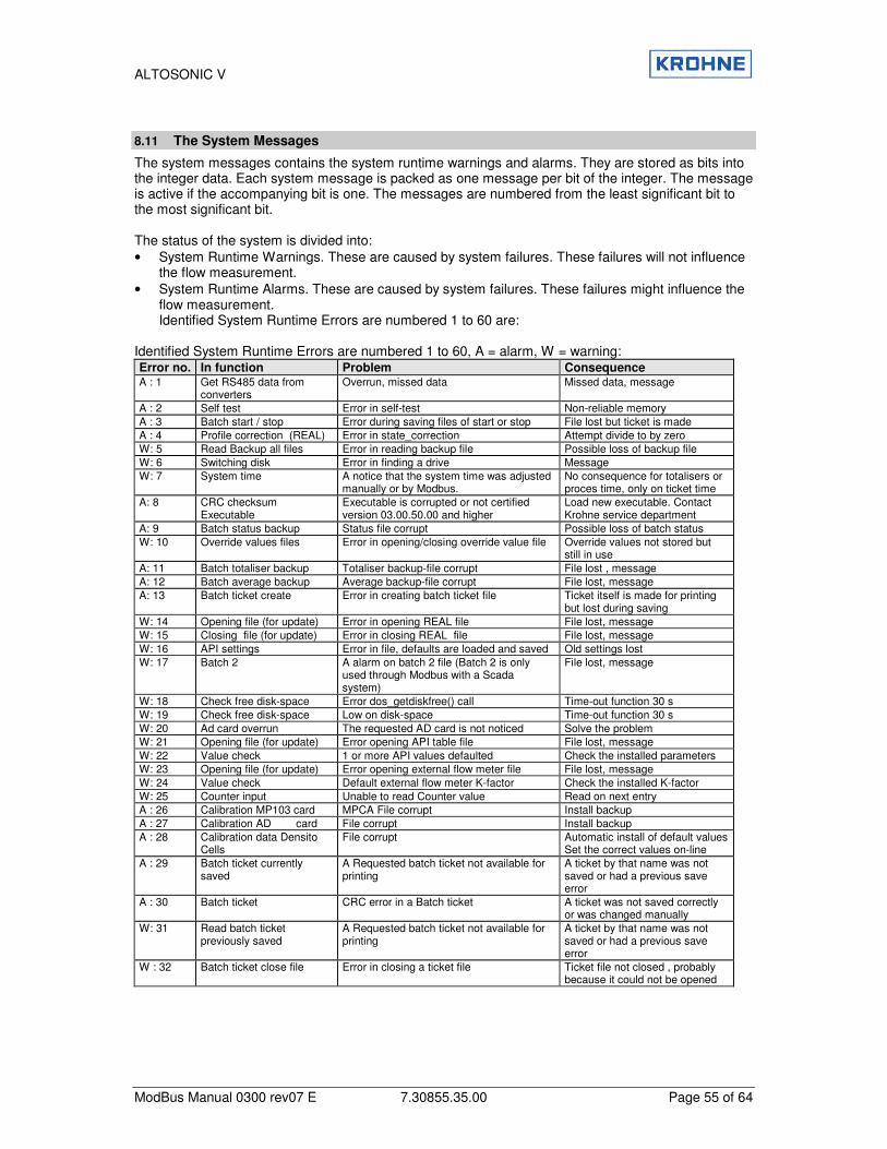
ALTOSONIC V
ModBus Manual 0300 rev07 E 7.30855.35.00 Page 55 of 64
8.11 The System Messages
The system messages contains the system runtime warnings and alarms. They are stored as bits into the integer data. Each system message is packed as one message per bit of the integer. The message is active if the accompanying bit is one. The messages are numbered from the least significant bit to the most significant bit. The status of the system is divided into: • System Runtime Warnings. These are caused by system failures. These failures will not influence
the flow measurement. • System Runtime Alarms. These are caused by system failures. These failures might influence the
flow measurement. Identified System Runtime Errors are numbered 1 to 60 are:
Identified System Runtime Errors are numbered 1 to 60, A = alarm, W = warning: Error no. In function Problem Consequence A : 1 Get RS485 data from
converters Overrun, missed data Missed data, message
A : 2 Self test Error in self-test Non-reliable memory A : 3 Batch start / stop Error during saving files of start or stop File lost but ticket is made A : 4 Profile correction (REAL) Error in state_correction Attempt divide to by zero W: 5 Read Backup all files Error in reading backup file Possible loss of backup file W: 6 Switching disk Error in finding a drive Message W: 7 System time A notice that the system time was adjusted
manually or by Modbus. No consequence for totalisers or proces time, only on ticket time
A: 8 CRC checksum Executable
Executable is corrupted or not certified version 03.00.50.00 and higher
Load new executable. Contact Krohne service department
A: 9 Batch status backup Status file corrupt Possible loss of batch status W: 10 Override values files Error in opening/closing override value file Override values not stored but
still in use A: 11 Batch totaliser backup Totaliser backup-file corrupt File lost , message A: 12 Batch average backup Average backup-file corrupt File lost, message A: 13 Batch ticket create Error in creating batch ticket file Ticket itself is made for printing
but lost during saving W: 14 Opening file (for update) Error in opening REAL file File lost, message W: 15 Closing file (for update) Error in closing REAL file File lost, message W: 16 API settings Error in file, defaults are loaded and saved Old settings lost W: 17 Batch 2 A alarm on batch 2 file (Batch 2 is only
used through Modbus with a Scada system)
File lost, message
W: 18 Check free disk-space Error dos_getdiskfree() call Time-out function 30 s W: 19 Check free disk-space Low on disk-space Time-out function 30 s W: 20 Ad card overrun The requested AD card is not noticed Solve the problem W: 21 Opening file (for update) Error opening API table file File lost, message W: 22 Value check 1 or more API values defaulted Check the installed parameters W: 23 Opening file (for update) Error opening external flow meter file File lost, message W: 24 Value check Default external flow meter K-factor Check the installed K-factor W: 25 Counter input Unable to read Counter value Read on next entry A : 26 Calibration MP103 card MPCA File corrupt Install backup A : 27 Calibration AD card File corrupt Install backup A : 28 Calibration data Densito
Cells File corrupt Automatic install of default values
Set the correct values on-line A : 29 Batch ticket currently
saved A Requested batch ticket not available for printing
A ticket by that name was not saved or had a previous save error
A : 30 Batch ticket CRC error in a Batch ticket A ticket was not saved correctly or was changed manually
W: 31 Read batch ticket previously saved
A Requested batch ticket not available for printing
A ticket by that name was not saved or had a previous save error
W : 32 Batch ticket close file Error in closing a ticket file Ticket file not closed , probably because it could not be opened
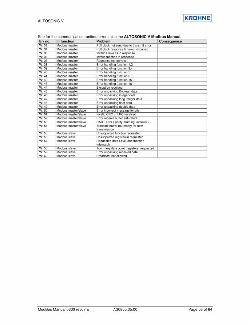
ALTOSONIC V
ModBus Manual 0300 rev07 E 7.30855.35.00 Page 56 of 64
See for the communication runtime errors also the ALTOSONIC V Modbus Manual. Err no. In function Problem Consequence W: 33 Modbus master Poll block not send due to transmit error W: 34 Modbus master Poll block response time-out occurred W: 35 Modbus master Invalid Slave ID in response W: 36 Modbus master Invalid function in response W: 37 Modbus master Response not correct W: 38 Modbus master Error handling function 1,2 W: 39 Modbus master Error handling function 3,4 W: 40 Modbus master Error handling function 5 W: 41 Modbus master Error handling function 6 W: 42 Modbus master Error handling function 15 W: 43 Modbus master Error handling function 16 W: 44 Modbus master Exception received W: 45 Modbus master Error unpacking Boolean data W: 46 Modbus master Error unpacking integer data W: 47 Modbus master Error unpacking long integer data W: 48 Modbus master Error unpacking float data W: 49 Modbus master Error unpacking double data W: 50 Modbus master/slave Error incorrect message length W: 51 Modbus master/slave Invalid CRC or LRC received W: 52 Modbus master/slave Error receive buffer saturated W: 53 Modbus master/slave UART error ( parity, framing, overrun ) W: 54 Modbus master/slave Transmit buffer not empty for new
transmission
W: 55 Modbus slave Unsupported function requested W: 56 Modbus slave Unsupported register(s) requested W: 57 Modbus slave Requested data Level and function
mismatch
W: 58 Modbus slave Too many data point (registers) requested W: 59 Modbus slave Error unpacking received data W: 60 Modbus slave Broadcast not allowed

ALTOSONIC V
ModBus Manual 0300 rev07 E 7.30855.35.00 Page 57 of 64
9 Appendices
9.1 Appendix A: Time out values
The character length lies between 9 and 12 bits The UFP-V determines the time between two bytes to recognise a communication failure or the end of a message. UFP-V discriminates between a timeout between 2 bytes and a timeout after the last byte, which occurs at the end of a message. The time between two bytes is measured with a resolution of ±100 us. To detect the timeout state (end of message) a timer is incremented every millisecond. A received byte will reset the timer. Every millisecond the timer value will be checked for a timeout value, when it will exceed a defined value it will mark the last received byte as end of message. Notice that the serial communication is a asynchrony process with respect to the used timer interrupt, therefore a ‘jitter’ of 1 ms must be taken into account. Modbus defined timeout values for every baud rate with N number of bytes:
Baud rate
9 bit 10 bit 11 bit 12 bit
Timeout chars
3.5 4.0 3.5 4.0 3.5 4.0 3.5 4.0
1200 26.25 ms 30 ms 29.17 ms 33.34 ms 32.08 ms 36.67 ms 35.00 ms 40 ms 2400 13.16 ms 15 ms 14.58 ms 6.67 ms 16.04 ms 18.33 ms 17.50 ms 20 ms 4800 6.56 ms 7.5 ms 7.29 ms 8.33 ms 8.02 ms 9.17 ms 8.75 ms 10 ms 9600 3.28 ms 3.75 ms 3.65 ms 4.16 ms 4.01 ms 4.58 ms 4.38 ms 5 ms 19200 1.64 ms 1.88 ms 1.82 ms 2.08 ms 2.01 ms 2.29 ms 2.19 ms 2.5 ms
The maximum time to detect a timeout (end of message) used in UFP-V:
Baud rate 9 10 11 12 1200 28…29 ms 31…32 ms 33…34 ms 36…37 ms 2400 14…15 ms 15…16 ms 16…17 ms 18…19 ms 4800 6…7 ms 7…8 ms 8…9 ms 9…10 ms 9600 3…4 ms 3…4 ms 4…5 ms 4…5 ms 19200 2…3 ms 2…3 ms 2…3 ms 2…3 ms
The maximum time between 2 characters in a message (GAP) used in UFP-V:
Baud rate 9 10 11 12 1200 28.2 ms 31.3 ms 34.4 ms 37.5 ms 2400 14.1 ms 15.6 ms 17.2 ms 8.8 ms 4800 7.0 ms 7.8 ms 8.6 ms 9.4 ms 9600 3.5 ms 3.9 ms 4.3 ms 4.7 ms 19200 1.8 ms 1.95 ms 2.2 ms 2.4 ms
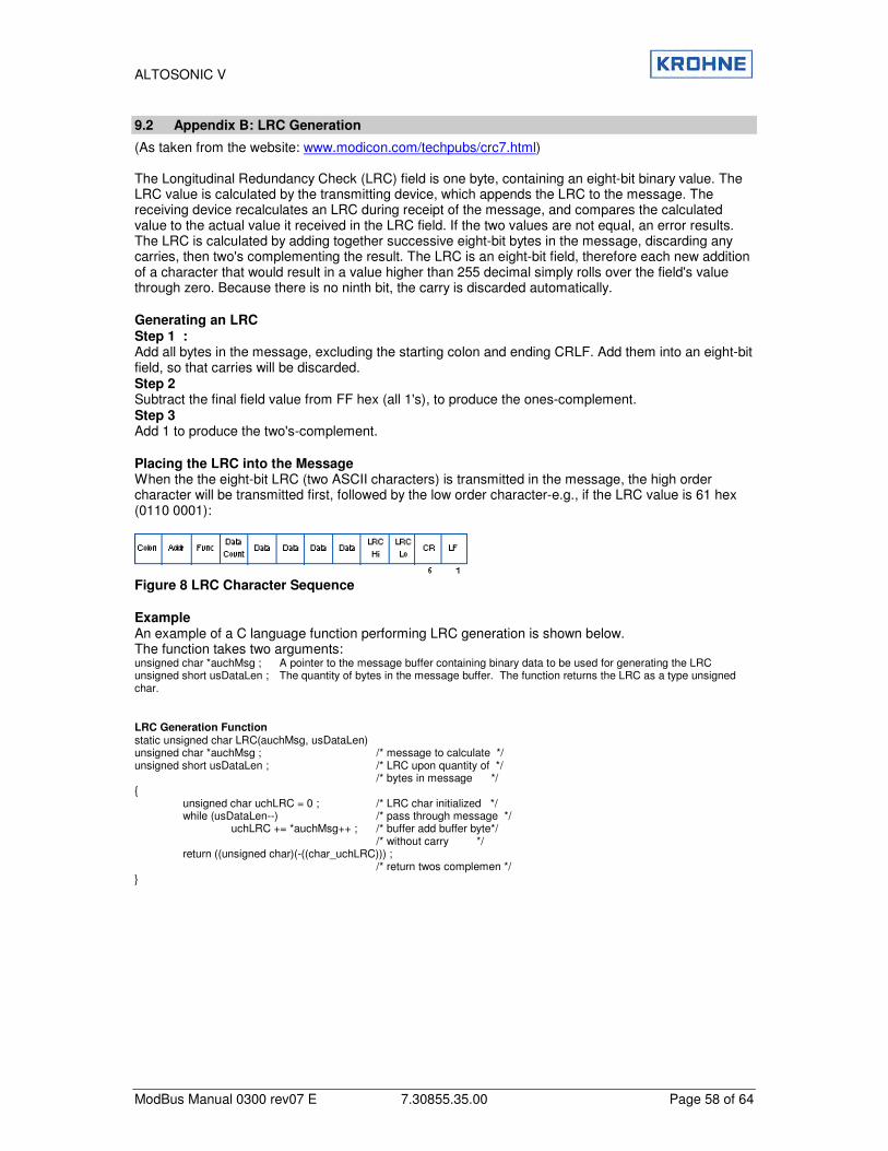
ALTOSONIC V
ModBus Manual 0300 rev07 E 7.30855.35.00 Page 58 of 64
9.2 Appendix B: LRC Generation
(As taken from the website: www.modicon.com/techpubs/crc7.html) The Longitudinal Redundancy Check (LRC) field is one byte, containing an eight-bit binary value. The LRC value is calculated by the transmitting device, which appends the LRC to the message. The receiving device recalculates an LRC during receipt of the message, and compares the calculated value to the actual value it received in the LRC field. If the two values are not equal, an error results. The LRC is calculated by adding together successive eight-bit bytes in the message, discarding any carries, then two's complementing the result. The LRC is an eight-bit field, therefore each new addition of a character that would result in a value higher than 255 decimal simply rolls over the field's value through zero. Because there is no ninth bit, the carry is discarded automatically. Generating an LRC Step 1 : Add all bytes in the message, excluding the starting colon and ending CRLF. Add them into an eight-bit field, so that carries will be discarded. Step 2 Subtract the final field value from FF hex (all 1's), to produce the ones-complement. Step 3 Add 1 to produce the two's-complement. Placing the LRC into the Message When the the eight-bit LRC (two ASCII characters) is transmitted in the message, the high order character will be transmitted first, followed by the low order character-e.g., if the LRC value is 61 hex (0110 0001):
Figure 8 LRC Character Sequence Example An example of a C language function performing LRC generation is shown below. The function takes two arguments: unsigned char *auchMsg ; A pointer to the message buffer containing binary data to be used for generating the LRC unsigned short usDataLen ; The quantity of bytes in the message buffer. The function returns the LRC as a type unsigned char. LRC Generation Function static unsigned char LRC(auchMsg, usDataLen) unsigned char *auchMsg ; /* message to calculate */ unsigned short usDataLen ; /* LRC upon quantity of */ /* bytes in message */ {
unsigned char uchLRC = 0 ; /* LRC char initialized */ while (usDataLen--) /* pass through message */ uchLRC += *auchMsg++ ; /* buffer add buffer byte*/ /* without carry */ return ((unsigned char)(-((char_uchLRC))) ; /* return twos complemen */ }
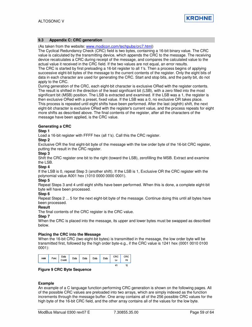
ALTOSONIC V
ModBus Manual 0300 rev07 E 7.30855.35.00 Page 59 of 64
9.3 Appendix C: CRC generation
(As taken from the website: www.modicon.com/techpubs/crc7.html) The Cyclical Redundancy Check (CRC) field is two bytes, containing a 16-bit binary value. The CRC value is calculated by the transmitting device, which appends the CRC to the message. The receiving device recalculates a CRC during receipt of the message, and compares the calculated value to the actual value it received in the CRC field. If the two values are not equal, an error results. The CRC is started by first preloading a 16-bit register to all 1's. Then a process begins of applying successive eight-bit bytes of the message to the current contents of the register. Only the eight bits of data in each character are used for generating the CRC. Start and stop bits, and the parity bit, do not apply to the CRC. During generation of the CRC, each eight-bit character is exclusive ORed with the register contents. The result is shifted in the direction of the least significant bit (LSB), with a zero filled into the most significant bit (MSB) position. The LSB is extracted and examined. If the LSB was a 1, the register is then exclusive ORed with a preset, fixed value. If the LSB was a 0, no exclusive OR takes place. This process is repeated until eight shifts have been performed. After the last (eighth) shift, the next eight-bit character is exclusive ORed with the register's current value, and the process repeats for eight more shifts as described above. The final contents of the register, after all the characters of the message have been applied, is the CRC value. Generating a CRC Step 1 Load a 16-bit register with FFFF hex (all 1's). Call this the CRC register. Step 2 Exclusive OR the first eight-bit byte of the message with the low order byte of the 16-bit CRC register, putting the result in the CRC register. Step 3 Shift the CRC register one bit to the right (toward the LSB), zerofilling the MSB. Extract and examine the LSB. Step 4 If the LSB is 0, repeat Step 3 (another shift). If the LSB is 1, Exclusive OR the CRC register with the polynomial value A001 hex (1010 0000 0000 0001). Step 5 Repeat Steps 3 and 4 until eight shifts have been performed. When this is done, a complete eight-bit byte will have been processed. Step 6 Repeat Steps 2 ... 5 for the next eight-bit byte of the message. Continue doing this until all bytes have been processed. Result The final contents of the CRC register is the CRC value. Step 7 When the CRC is placed into the message, its upper and lower bytes must be swapped as described below. Placing the CRC into the Message When the 16-bit CRC (two eight-bit bytes) is transmitted in the message, the low order byte will be transmitted first, followed by the high order byte-e.g., if the CRC value is 1241 hex (0001 0010 0100 0001):
Figure 9 CRC Byte Sequence Example An example of a C language function performing CRC generation is shown on the following pages. All of the possible CRC values are preloaded into two arrays, which are simply indexed as the function increments through the message buffer. One array contains all of the 256 possible CRC values for the high byte of the 16-bit CRC field, and the other array contains all of the values for the low byte.
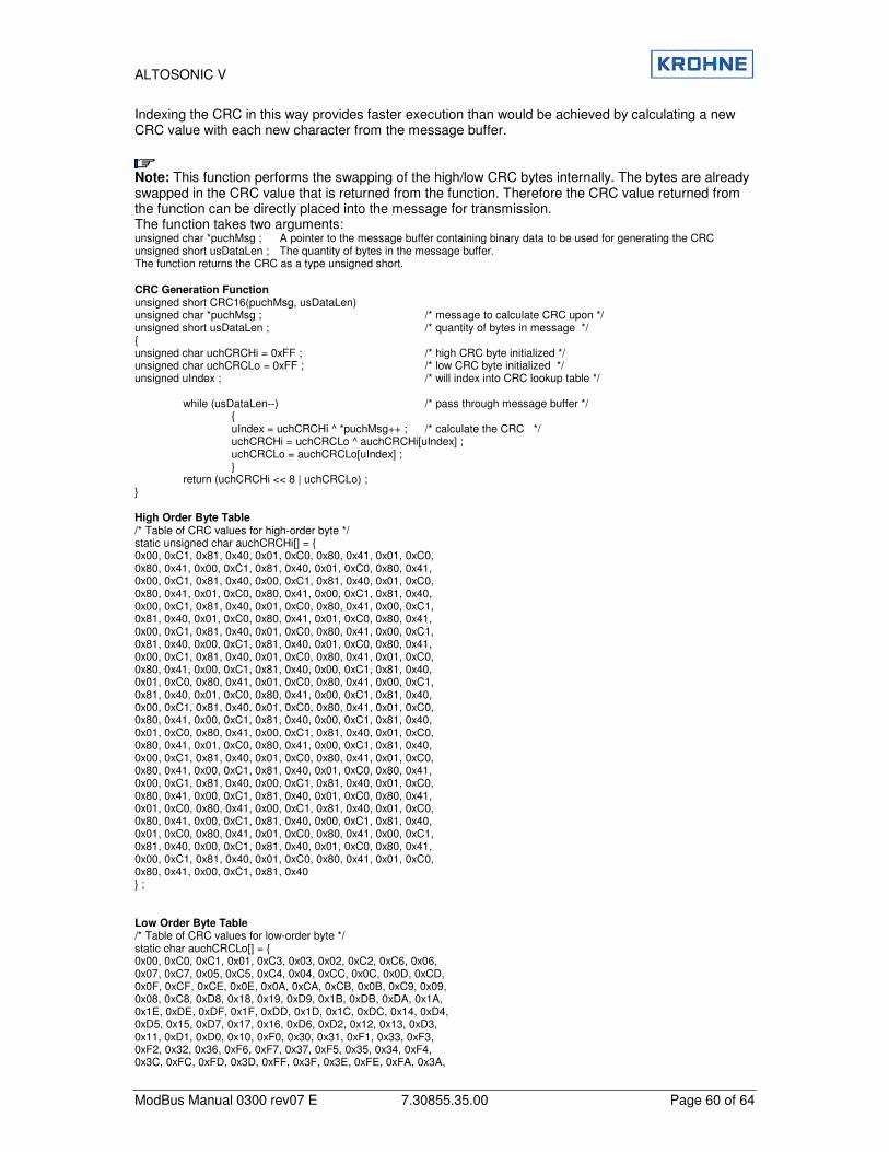
ALTOSONIC V
ModBus Manual 0300 rev07 E 7.30855.35.00 Page 60 of 64
Indexing the CRC in this way provides faster execution than would be achieved by calculating a new CRC value with each new character from the message buffer.
Note: This function performs the swapping of the high/low CRC bytes internally. The bytes are already swapped in the CRC value that is returned from the function. Therefore the CRC value returned from the function can be directly placed into the message for transmission. The function takes two arguments: unsigned char *puchMsg ; A pointer to the message buffer containing binary data to be used for generating the CRC unsigned short usDataLen ; The quantity of bytes in the message buffer. The function returns the CRC as a type unsigned short.
CRC Generation Function unsigned short CRC16(puchMsg, usDataLen) unsigned char *puchMsg ; /* message to calculate CRC upon */ unsigned short usDataLen ; /* quantity of bytes in message */ { unsigned char uchCRCHi = 0xFF ; /* high CRC byte initialized */ unsigned char uchCRCLo = 0xFF ; /* low CRC byte initialized */ unsigned uIndex ; /* will index into CRC lookup table */ while (usDataLen--) /* pass through message buffer */ { uIndex = uchCRCHi ^ *puchMsg++ ; /* calculate the CRC */ uchCRCHi = uchCRCLo ^ auchCRCHi[uIndex] ; uchCRCLo = auchCRCLo[uIndex] ; } return (uchCRCHi << 8 | uchCRCLo) ; } High Order Byte Table /* Table of CRC values for high-order byte */ static unsigned char auchCRCHi[] = { 0x00, 0xC1, 0x81, 0x40, 0x01, 0xC0, 0x80, 0x41, 0x01, 0xC0, 0x80, 0x41, 0x00, 0xC1, 0x81, 0x40, 0x01, 0xC0, 0x80, 0x41, 0x00, 0xC1, 0x81, 0x40, 0x00, 0xC1, 0x81, 0x40, 0x01, 0xC0, 0x80, 0x41, 0x01, 0xC0, 0x80, 0x41, 0x00, 0xC1, 0x81, 0x40, 0x00, 0xC1, 0x81, 0x40, 0x01, 0xC0, 0x80, 0x41, 0x00, 0xC1, 0x81, 0x40, 0x01, 0xC0, 0x80, 0x41, 0x01, 0xC0, 0x80, 0x41, 0x00, 0xC1, 0x81, 0x40, 0x01, 0xC0, 0x80, 0x41, 0x00, 0xC1, 0x81, 0x40, 0x00, 0xC1, 0x81, 0x40, 0x01, 0xC0, 0x80, 0x41, 0x00, 0xC1, 0x81, 0x40, 0x01, 0xC0, 0x80, 0x41, 0x01, 0xC0, 0x80, 0x41, 0x00, 0xC1, 0x81, 0x40, 0x00, 0xC1, 0x81, 0x40, 0x01, 0xC0, 0x80, 0x41, 0x01, 0xC0, 0x80, 0x41, 0x00, 0xC1, 0x81, 0x40, 0x01, 0xC0, 0x80, 0x41, 0x00, 0xC1, 0x81, 0x40, 0x00, 0xC1, 0x81, 0x40, 0x01, 0xC0, 0x80, 0x41, 0x01, 0xC0, 0x80, 0x41, 0x00, 0xC1, 0x81, 0x40, 0x00, 0xC1, 0x81, 0x40, 0x01, 0xC0, 0x80, 0x41, 0x00, 0xC1, 0x81, 0x40, 0x01, 0xC0, 0x80, 0x41, 0x01, 0xC0, 0x80, 0x41, 0x00, 0xC1, 0x81, 0x40, 0x00, 0xC1, 0x81, 0x40, 0x01, 0xC0, 0x80, 0x41, 0x01, 0xC0, 0x80, 0x41, 0x00, 0xC1, 0x81, 0x40, 0x01, 0xC0, 0x80, 0x41, 0x00, 0xC1, 0x81, 0x40, 0x00, 0xC1, 0x81, 0x40, 0x01, 0xC0, 0x80, 0x41, 0x00, 0xC1, 0x81, 0x40, 0x01, 0xC0, 0x80, 0x41, 0x01, 0xC0, 0x80, 0x41, 0x00, 0xC1, 0x81, 0x40, 0x01, 0xC0, 0x80, 0x41, 0x00, 0xC1, 0x81, 0x40, 0x00, 0xC1, 0x81, 0x40, 0x01, 0xC0, 0x80, 0x41, 0x01, 0xC0, 0x80, 0x41, 0x00, 0xC1, 0x81, 0x40, 0x00, 0xC1, 0x81, 0x40, 0x01, 0xC0, 0x80, 0x41, 0x00, 0xC1, 0x81, 0x40, 0x01, 0xC0, 0x80, 0x41, 0x01, 0xC0, 0x80, 0x41, 0x00, 0xC1, 0x81, 0x40 } ; Low Order Byte Table /* Table of CRC values for low-order byte */ static char auchCRCLo[] = { 0x00, 0xC0, 0xC1, 0x01, 0xC3, 0x03, 0x02, 0xC2, 0xC6, 0x06, 0x07, 0xC7, 0x05, 0xC5, 0xC4, 0x04, 0xCC, 0x0C, 0x0D, 0xCD, 0x0F, 0xCF, 0xCE, 0x0E, 0x0A, 0xCA, 0xCB, 0x0B, 0xC9, 0x09, 0x08, 0xC8, 0xD8, 0x18, 0x19, 0xD9, 0x1B, 0xDB, 0xDA, 0x1A, 0x1E, 0xDE, 0xDF, 0x1F, 0xDD, 0x1D, 0x1C, 0xDC, 0x14, 0xD4, 0xD5, 0x15, 0xD7, 0x17, 0x16, 0xD6, 0xD2, 0x12, 0x13, 0xD3, 0x11, 0xD1, 0xD0, 0x10, 0xF0, 0x30, 0x31, 0xF1, 0x33, 0xF3, 0xF2, 0x32, 0x36, 0xF6, 0xF7, 0x37, 0xF5, 0x35, 0x34, 0xF4, 0x3C, 0xFC, 0xFD, 0x3D, 0xFF, 0x3F, 0x3E, 0xFE, 0xFA, 0x3A,

ALTOSONIC V
ModBus Manual 0300 rev07 E 7.30855.35.00 Page 61 of 64
0x3B, 0xFB, 0x39, 0xF9, 0xF8, 0x38, 0x28, 0xE8, 0xE9, 0x29, 0xEB, 0x2B, 0x2A, 0xEA, 0xEE, 0x2E, 0x2F, 0xEF, 0x2D, 0xED, 0xEC, 0x2C, 0xE4, 0x24, 0x25, 0xE5, 0x27, 0xE7, 0xE6, 0x26, 0x22, 0xE2, 0xE3, 0x23, 0xE1, 0x21, 0x20, 0xE0, 0xA0, 0x60, 0x61, 0xA1, 0x63, 0xA3, 0xA2, 0x62, 0x66, 0xA6, 0xA7, 0x67, 0xA5, 0x65, 0x64, 0xA4, 0x6C, 0xAC, 0xAD, 0x6D, 0xAF, 0x6F, 0x6E, 0xAE, 0xAA, 0x6A, 0x6B, 0xAB, 0x69, 0xA9, 0xA8, 0x68, 0x78, 0xB8, 0xB9, 0x79, 0xBB, 0x7B, 0x7A, 0xBA, 0xBE, 0x7E, 0x7F, 0xBF, 0x7D, 0xBD, 0xBC, 0x7C, 0xB4, 0x74, 0x75, 0xB5, 0x77, 0xB7, 0xB6, 0x76, 0x72, 0xB2, 0xB3, 0x73, 0xB1, 0x71, 0x70, 0xB0, 0x50, 0x90, 0x91, 0x51, 0x93, 0x53, 0x52, 0x92, 0x96, 0x56, 0x57, 0x97, 0x55, 0x95, 0x94, 0x54, 0x9C, 0x5C, 0x5D, 0x9D, 0x5F, 0x9F, 0x9E, 0x5E, 0x5A, 0x9A, 0x9B, 0x5B, 0x99, 0x59, 0x58, 0x98, 0x88, 0x48, 0x49, 0x89, 0x4B, 0x8B, 0x8A, 0x4A, 0x4E, 0x8E, 0x8F, 0x4F, 0x8D, 0x4D, 0x4C, 0x8C, 0x44, 0x84, 0x85, 0x45, 0x87, 0x47, 0x46, 0x86, 0x82, 0x42, 0x43, 0x83, 0x41, 0x81, 0x80, 0x40 } ;
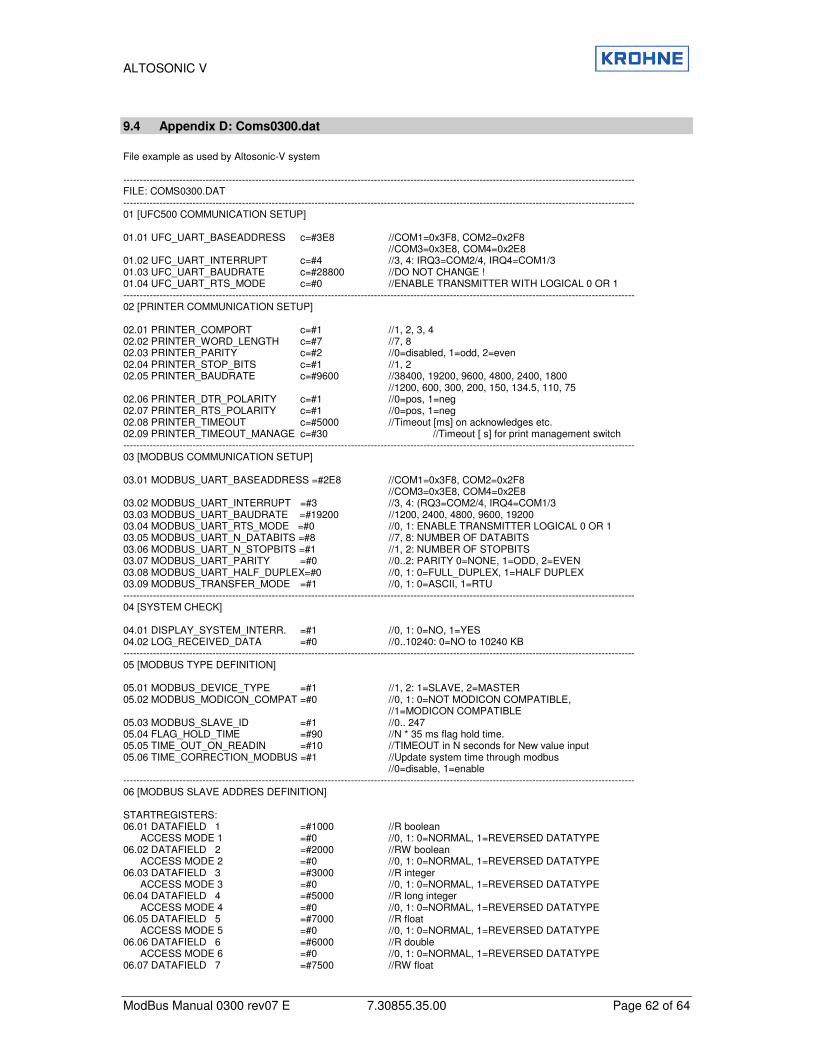
ALTOSONIC V
ModBus Manual 0300 rev07 E 7.30855.35.00 Page 62 of 64
9.4 Appendix D: Coms0300.dat
File example as used by Altosonic-V system ----------------------------------------------------------------------------------------------------------------------------------------------------------- FILE: COMS0300.DAT ----------------------------------------------------------------------------------------------------------------------------------------------------------- 01 [UFC500 COMMUNICATION SETUP] 01.01 UFC_UART_BASEADDRESS c=#3E8 //COM1=0x3F8, COM2=0x2F8 //COM3=0x3E8, COM4=0x2E8 01.02 UFC_UART_INTERRUPT c=#4 //3, 4: IRQ3=COM2/4, IRQ4=COM1/3 01.03 UFC_UART_BAUDRATE c=#28800 //DO NOT CHANGE ! 01.04 UFC_UART_RTS_MODE c=#0 //ENABLE TRANSMITTER WITH LOGICAL 0 OR 1 ----------------------------------------------------------------------------------------------------------------------------------------------------------- 02 [PRINTER COMMUNICATION SETUP] 02.01 PRINTER_COMPORT c=#1 //1, 2, 3, 4 02.02 PRINTER_WORD_LENGTH c=#7 //7, 8 02.03 PRINTER_PARITY c=#2 //0=disabled, 1=odd, 2=even 02.04 PRINTER_STOP_BITS c=#1 //1, 2 02.05 PRINTER_BAUDRATE c=#9600 //38400, 19200, 9600, 4800, 2400, 1800 //1200, 600, 300, 200, 150, 134.5, 110, 75 02.06 PRINTER_DTR_POLARITY c=#1 //0=pos, 1=neg 02.07 PRINTER_RTS_POLARITY c=#1 //0=pos, 1=neg 02.08 PRINTER_TIMEOUT c=#5000 //Timeout [ms] on acknowledges etc. 02.09 PRINTER_TIMEOUT_MANAGE c=#30 //Timeout [ s] for print management switch ----------------------------------------------------------------------------------------------------------------------------------------------------------- 03 [MODBUS COMMUNICATION SETUP] 03.01 MODBUS_UART_BASEADDRESS =#2E8 //COM1=0x3F8, COM2=0x2F8 //COM3=0x3E8, COM4=0x2E8 03.02 MODBUS_UART_INTERRUPT =#3 //3, 4: (RQ3=COM2/4, IRQ4=COM1/3 03.03 MODBUS_UART_BAUDRATE =#19200 //1200, 2400, 4800, 9600, 19200 03.04 MODBUS_UART_RTS_MODE =#0 //0, 1: ENABLE TRANSMITTER LOGICAL 0 OR 1 03.05 MODBUS_UART_N_DATABITS =#8 //7, 8: NUMBER OF DATABITS 03.06 MODBUS_UART_N_STOPBITS =#1 //1, 2: NUMBER OF STOPBITS 03.07 MODBUS_UART_PARITY =#0 //0..2: PARITY 0=NONE, 1=ODD, 2=EVEN 03.08 MODBUS_UART_HALF_DUPLEX=#0 //0, 1: 0=FULL_DUPLEX, 1=HALF DUPLEX 03.09 MODBUS_TRANSFER_MODE =#1 //0, 1: 0=ASCII, 1=RTU ----------------------------------------------------------------------------------------------------------------------------------------------------------- 04 [SYSTEM CHECK] 04.01 DISPLAY_SYSTEM_INTERR. =#1 //0, 1: 0=NO, 1=YES 04.02 LOG_RECEIVED_DATA =#0 //0..10240: 0=NO to 10240 KB ----------------------------------------------------------------------------------------------------------------------------------------------------------- 05 [MODBUS TYPE DEFINITION] 05.01 MODBUS_DEVICE_TYPE =#1 //1, 2: 1=SLAVE, 2=MASTER 05.02 MODBUS_MODICON_COMPAT =#0 //0, 1: 0=NOT MODICON COMPATIBLE, //1=MODICON COMPATIBLE 05.03 MODBUS_SLAVE_ID =#1 //0.. 247 05.04 FLAG_HOLD_TIME =#90 //N * 35 ms flag hold time. 05.05 TIME_OUT_ON_READIN =#10 //TIMEOUT in N seconds for New value input 05.06 TIME_CORRECTION_MODBUS =#1 //Update system time through modbus //0=disable, 1=enable ----------------------------------------------------------------------------------------------------------------------------------------------------------- 06 [MODBUS SLAVE ADDRES DEFINITION] STARTREGISTERS: 06.01 DATAFIELD 1 =#1000 //R boolean ACCESS MODE 1 =#0 //0, 1: 0=NORMAL, 1=REVERSED DATATYPE 06.02 DATAFIELD 2 =#2000 //RW boolean ACCESS MODE 2 =#0 //0, 1: 0=NORMAL, 1=REVERSED DATATYPE 06.03 DATAFIELD 3 =#3000 //R integer ACCESS MODE 3 =#0 //0, 1: 0=NORMAL, 1=REVERSED DATATYPE 06.04 DATAFIELD 4 =#5000 //R long integer ACCESS MODE 4 =#0 //0, 1: 0=NORMAL, 1=REVERSED DATATYPE 06.05 DATAFIELD 5 =#7000 //R float ACCESS MODE 5 =#0 //0, 1: 0=NORMAL, 1=REVERSED DATATYPE 06.06 DATAFIELD 6 =#6000 //R double ACCESS MODE 6 =#0 //0, 1: 0=NORMAL, 1=REVERSED DATATYPE 06.07 DATAFIELD 7 =#7500 //RW float
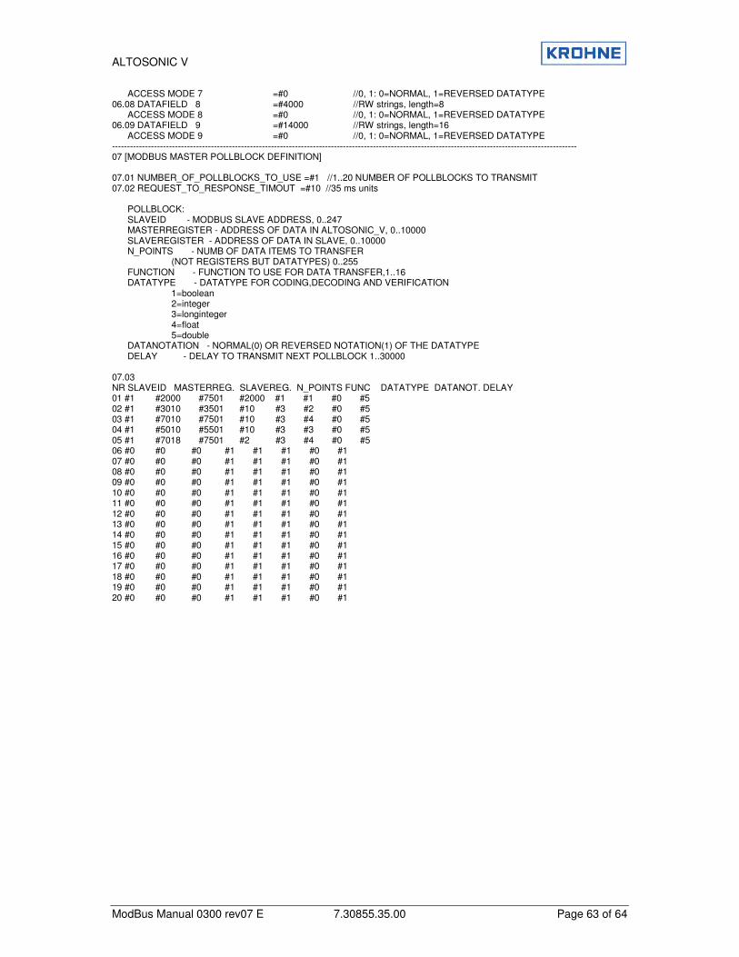
ALTOSONIC V
ModBus Manual 0300 rev07 E 7.30855.35.00 Page 63 of 64
ACCESS MODE 7 =#0 //0, 1: 0=NORMAL, 1=REVERSED DATATYPE 06.08 DATAFIELD 8 =#4000 //RW strings, length=8 ACCESS MODE 8 =#0 //0, 1: 0=NORMAL, 1=REVERSED DATATYPE 06.09 DATAFIELD 9 =#14000 //RW strings, length=16 ACCESS MODE 9 =#0 //0, 1: 0=NORMAL, 1=REVERSED DATATYPE ----------------------------------------------------------------------------------------------------------------------------------------------------------- 07 [MODBUS MASTER POLLBLOCK DEFINITION] 07.01 NUMBER_OF_POLLBLOCKS_TO_USE =#1 //1..20 NUMBER OF POLLBLOCKS TO TRANSMIT 07.02 REQUEST_TO_RESPONSE_TIMOUT =#10 //35 ms units POLLBLOCK: SLAVEID - MODBUS SLAVE ADDRESS, 0..247 MASTERREGISTER - ADDRESS OF DATA IN ALTOSONIC_V, 0..10000 SLAVEREGISTER - ADDRESS OF DATA IN SLAVE, 0..10000 N_POINTS - NUMB OF DATA ITEMS TO TRANSFER (NOT REGISTERS BUT DATATYPES) 0..255 FUNCTION - FUNCTION TO USE FOR DATA TRANSFER,1..16 DATATYPE - DATATYPE FOR CODING,DECODING AND VERIFICATION 1=boolean 2=integer 3=longinteger 4=float 5=double DATANOTATION - NORMAL(0) OR REVERSED NOTATION(1) OF THE DATATYPE DELAY - DELAY TO TRANSMIT NEXT POLLBLOCK 1..30000 07.03 NR SLAVEID MASTERREG. SLAVEREG. N_POINTS FUNC DATATYPE DATANOT. DELAY 01 #1 #2000 #7501 #2000 #1 #1 #0 #5 02 #1 #3010 #3501 #10 #3 #2 #0 #5 03 #1 #7010 #7501 #10 #3 #4 #0 #5 04 #1 #5010 #5501 #10 #3 #3 #0 #5 05 #1 #7018 #7501 #2 #3 #4 #0 #5 06 #0 #0 #0 #1 #1 #1 #0 #1 07 #0 #0 #0 #1 #1 #1 #0 #1 08 #0 #0 #0 #1 #1 #1 #0 #1 09 #0 #0 #0 #1 #1 #1 #0 #1 10 #0 #0 #0 #1 #1 #1 #0 #1 11 #0 #0 #0 #1 #1 #1 #0 #1 12 #0 #0 #0 #1 #1 #1 #0 #1 13 #0 #0 #0 #1 #1 #1 #0 #1 14 #0 #0 #0 #1 #1 #1 #0 #1 15 #0 #0 #0 #1 #1 #1 #0 #1 16 #0 #0 #0 #1 #1 #1 #0 #1 17 #0 #0 #0 #1 #1 #1 #0 #1 18 #0 #0 #0 #1 #1 #1 #0 #1 19 #0 #0 #0 #1 #1 #1 #0 #1 20 #0 #0 #0 #1 #1 #1 #0 #1

Australia France Norway
KROHNE Australia Pty Ltd. KROHNE S.A. Krohne Instrumentation A.S.Unit 19 No. 9, Hudson Ave. Usine des Ors Ekholtveien 114 Algeria JapanCastle Hill 2154, NSW B.P. 98 NO-1526 Moss Argentina JordanTEL.: +61(0)2-98948711 F-26 103 Romans Cedex P.O. Box 2178, NO-1521 Moss Bulgaria KuwaitFAX: +61(0)2-98994855 TEL.: +33(0)4-75 05 44 00 TEL.: +47(0)69-264860 Camaroon Maroccoe-mail: [email protected] FAX: +33(0)4-75 05 00 48 FAX: +47(0)69-267333 Canada Mauritius
e-mail: [email protected] e-mail: [email protected] Chile MexicoAustria Internet: www.krohne.no Columbia New ZealandKROHNE Ges.m.b.H. Germany Croatia PakistanWagramerstr. 81 KROHNE Messtechnik South Africa Denmark PolandDonauzentrum GmbH & Co. KG KROHNE Pty. Ltd. Ecuador PortugalA-1220 Wien Ludwig-Krohne-Straße 163 New Road Egypt Saudi ArabiaTEL.: +43(0)1-2 03 45 32 D-47058 Duisburg Hulway House Ext. 13 Finland SenegalFAX: +43(0)1-2 03 47 78 TEL.: +49(0)203-301-0 Midrand French Antilles Singaporee-mail: [email protected] FAX: +49(0)203-301 389 TEL.: +27(0)11-315-2685 Greece Slovakia
e-mail: [email protected] FAX: +27(0)11-805-0531 Guinea SloveniaBelgium e-mail: [email protected] Hong Kong SwedenKROHNE Belgium N.V. India Hungary TaiwanBrusselstraat 320 KROHNE Marshall Ltd. Spain Indonesia ThailandB-1702 Groot Bijgaarden A-34/35, MIDC I.I. KROHNE Iberia, S.r.L. Ivory Coast TurkeyTEL.: +32(0)2-4 66 00 10 Industrial Estate; ‘H’-Block, Poligono Industrial Alcalá I Iran TunesiaFAX: +32(0)2-4 66 08 00 Pimpri Pune 411018 Calle El Escorial, Nave 206 Ireland Venezuelae-mail: [email protected] TEL.: +91(0)20 -747 01 21 E-28805 Alcalá de Henares -Madrid Israel Yugoslavia
TEL.: +91(0)20 -747 01 71 TEL.: +34(9)1-8 83 21 52Brazil FAX: +91(0)20 -747 70 49 FAX: +34(9)1-8 83 48 54KROHNE Conaut e-mail: [email protected] e-mail: [email protected] Automaticos Ltda.Estrada Das Águas Espraiadas, 230 C.P: 56 Italy Switzerland
06835 - 080 EMBU - SP KROHNE Italia Srl KROHNE AGTEL.: +55(0)11-4785-2700 Via V. Monti 75 Uferstr. 90FAX: +55(0)11-4785-2768 I-20145 Milano CH-4019 Basele-mail: [email protected] TEL.: +39(0)2-4 30 06 61 TEL.: +41(0)61-638 30 30
FAX: +39(0)2-43 00 66 66 FAX: +41(0)61-638 30 40China e-mail: [email protected] e-mail: [email protected] Measurement Instruments Co. Ltd.Room 7E, Yi Dian Mansion Korea United Kingdom
746 Zhao Jia Bang Road Hankuk KROHNE KROHNE Ltd.Shanghai 200030 2 F, 599-1 Rutherford DriveTEL.: +86(0)21-64677163 Banghwa-2-Dong Park Farm Industrial EstateFAX: +86(0)21-64677166 Kangseo-Ku Wellingborough,Cellphone: +86(0)139 1885890 Seoul Northants NN8 6AE, UKe-mail: [email protected] TEL.: +82(0)2665-85 23-4 TEL.: +44(0)19 33-408 500
FAX: +82(0)2665-85 25 FAX: +44(0)19 33-408 501CIS e-mail: [email protected] e-mail: [email protected] KROHNE Engineering AGBusiness-Centre Planeta, Office 403 Netherlands USA
ul. Marxistskaja 3 KROHNE Altometer KROHNE Inc.109147 Moscow/Russia Kerkeplaat 12 7 Dearborn RoadTEL.: +7(0)095-9117165 NL-3313 LC Dordrecht Peabody, MA 01960FAX: +7(0)095-9117231 TEL.: +31(0)78-6306300 TEL.: +1-978 535-60 60e-mail: [email protected] FAX: +31(0)78-6306390 FAX: +1-978 535-17 20
e-mail: [email protected] e-mail: [email protected] Republic
KROHNE CZ, spol. s r.o. KROHNE Persenaire B.V.Dráz?ní 7 Kerkeplaat 1262700 Brno NL-3313 LC DordrechtTEL.: +42(0)5-45513340 / 341 TEL.: +31(0)78-6306200FAX: +42(0)5-45513339 FAX: +31(0)78-6306234e-mail: [email protected] Service Direkt: +31(0)78-6306222
e-mail: [email protected]
Overseas Representatives
Other Countries:
KROHNE MesstechnikGmbH & Co. KG
e-mail: [email protected]
Subject to change without notice
Ludwig-Krohne-Str.D-47058 DuisburgTEL.: +49(0)203-301 309FAX: +49(0)203-301 389