Embed Size (px)
Citation preview
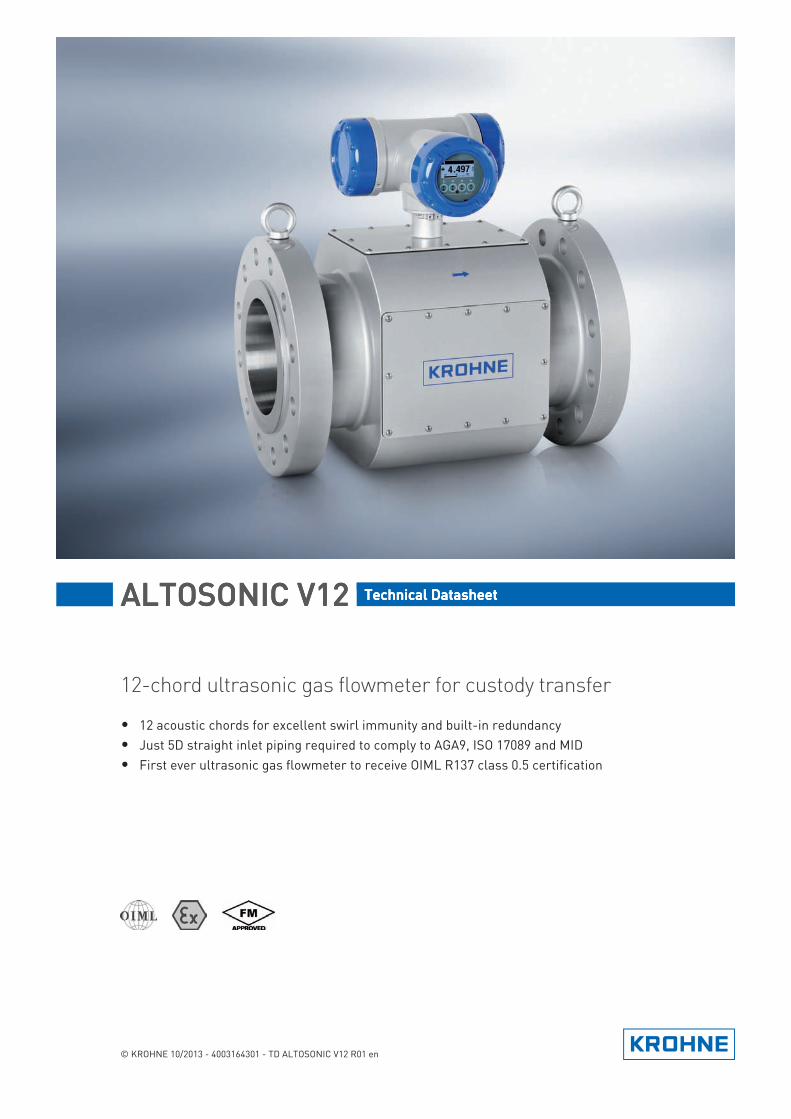
ALTOSONIC V12ALTOSONIC V12ALTOSONIC V12ALTOSONIC V12 Technical DatasheetTechnical DatasheetTechnical DatasheetTechnical Datasheet
12-chord ultrasonic gas flowmeter for custody transfer
• 12 acoustic chords for excellent swirl immunity and built-in redundancy• Just 5D straight inlet piping required to comply to AGA9, ISO 17089 and MID• First ever ultrasonic gas flowmeter to receive OIML R137 class 0.5 certification
© KROHNE 10/2013 - 4003164301 - TD ALTOSONIC V12 R01 en
CONTENTS
2 www.krohne.com 10/2013 - 4003164301 - TD ALTOSONIC V12 R01 en
ALTOSONIC V12
1 Product features 3
1.1 Custody transfer measurement of natural gas ............................................................... 31.2 Variants............................................................................................................................. 51.3 Features............................................................................................................................ 61.4 Measuring principle.......................................................................................................... 8
2 Technical data 9
2.1 Technical data table ......................................................................................................... 92.2 Dimensions and weights ................................................................................................ 132.3 Flow table ....................................................................................................................... 18
3 Installation 19
3.1 Intended use ................................................................................................................... 193.2 Pre-installation requirements ....................................................................................... 193.3 Installation...................................................................................................................... 19
3.3.1 Mounting position.................................................................................................................. 193.3.2 Pipe diameters and lengths.................................................................................................. 203.3.3 Flow conditioners.................................................................................................................. 203.3.4 Inlet and outlet for uni-directional use ................................................................................ 213.3.5 Control valves........................................................................................................................ 213.3.6 P and T sensors..................................................................................................................... 22
3.4 Temperatures ................................................................................................................. 23
4 Electrical connections 24
4.1 Safety instructions.......................................................................................................... 244.2 Digital I/O connections ................................................................................................... 24
4.2.1 Pulse and frequency output.................................................................................................. 254.2.2 Status outputs ....................................................................................................................... 254.2.3 Emulation of a turbine meter ............................................................................................... 26
4.3 Serial data communication (RS 485).............................................................................. 274.4 Power connection ........................................................................................................... 274.5 Cabling............................................................................................................................ 284.6 Grounding ....................................................................................................................... 29
5 Applications 30
5.1 Application Form ............................................................................................................ 30
6 Notes 35
PRODUCT FEATURES 1
3
ALTOSONIC V12
www.krohne.com10/2013 - 4003164301 - TD ALTOSONIC V12 R01 en
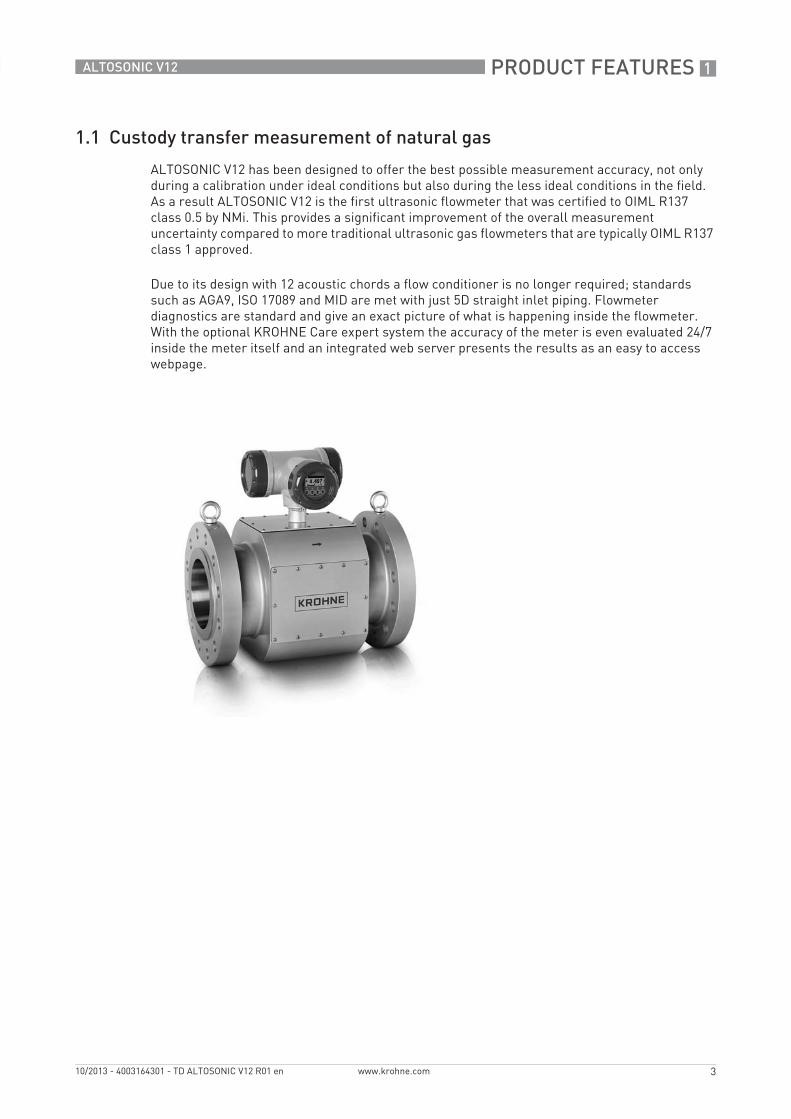
1.1 Custody transfer measurement of natural gas
ALTOSONIC V12 has been designed to offer the best possible measurement accuracy, not only during a calibration under ideal conditions but also during the less ideal conditions in the field. As a result ALTOSONIC V12 is the first ultrasonic flowmeter that was certified to OIML R137 class 0.5 by NMi. This provides a significant improvement of the overall measurement uncertainty compared to more traditional ultrasonic gas flowmeters that are typically OIML R137 class 1 approved.
Due to its design with 12 acoustic chords a flow conditioner is no longer required; standards such as AGA9, ISO 17089 and MID are met with just 5D straight inlet piping. Flowmeter diagnostics are standard and give an exact picture of what is happening inside the flowmeter. With the optional KROHNE Care expert system the accuracy of the meter is even evaluated 24/7 inside the meter itself and an integrated web server presents the results as an easy to access webpage.
1 PRODUCT FEATURES
4
ALTOSONIC V12
www.krohne.com 10/2013 - 4003164301 - TD ALTOSONIC V12 R01 en
Highlights• 12 acoustic chords for excellent swirl immunity and built-in redundancy• No flow conditioner required• Just 5D straight inlet piping required to comply to AGA9, ISO 17089 and MID• First ever ultrasonic flowmeter to receive OIML R137 class 0.5 approval by NMi• Meter accuracy evaluated 24/7 by optional web-based KROHNE Care expert system
Industries• Oil & Gas• Natural gas distribution• Large consumers of natural gas
Applications• Custody transfer and allocation measurement• Border stations• Large transfer points• Master metering• Check metering• LNG production and regasification
PRODUCT FEATURES 1
5
ALTOSONIC V12
www.krohne.com10/2013 - 4003164301 - TD ALTOSONIC V12 R01 en
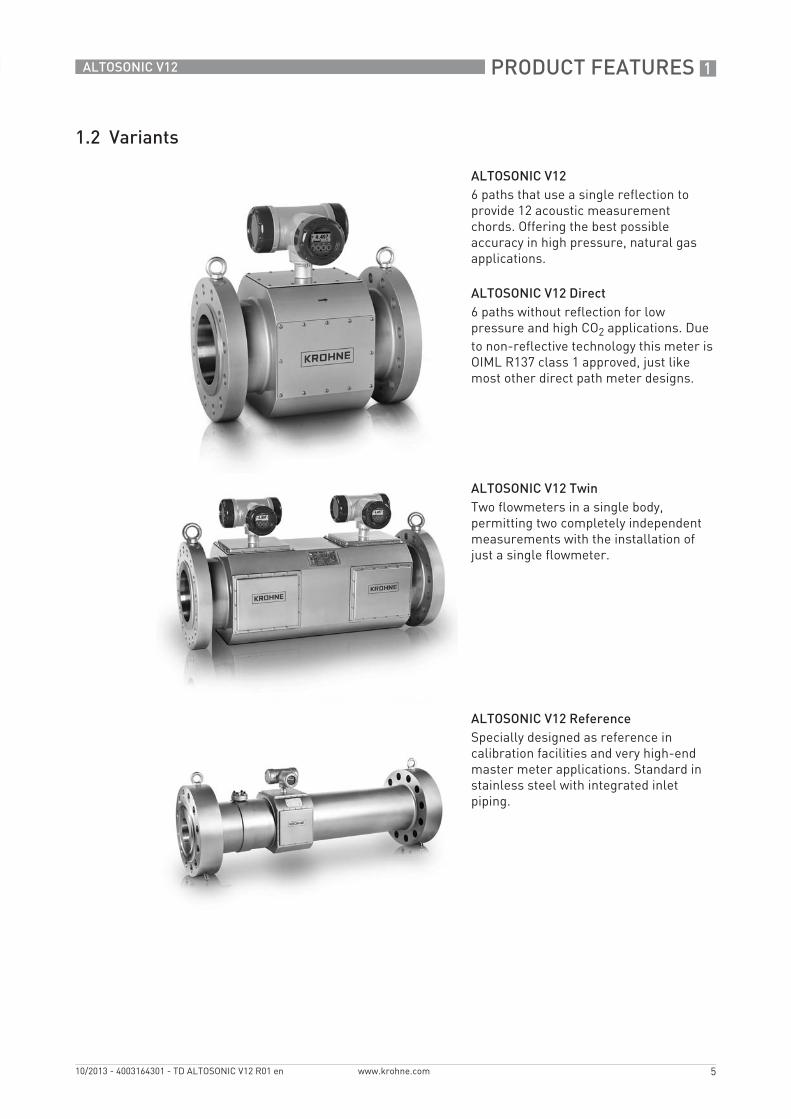
1.2 Variants
ALTOSONIC V126 paths that use a single reflection to provide 12 acoustic measurement chords. Offering the best possible accuracy in high pressure, natural gas applications.
ALTOSONIC V12 Direct6 paths without reflection for low pressure and high CO2 applications. Due to non-reflective technology this meter is OIML R137 class 1 approved, just like most other direct path meter designs.
ALTOSONIC V12 TwinTwo flowmeters in a single body, permitting two completely independent measurements with the installation of just a single flowmeter.
ALTOSONIC V12 ReferenceSpecially designed as reference in calibration facilities and very high-end master meter applications. Standard in stainless steel with integrated inlet piping.
1 PRODUCT FEATURES
6
ALTOSONIC V12
www.krohne.com 10/2013 - 4003164301 - TD ALTOSONIC V12 R01 en
1.3 Features
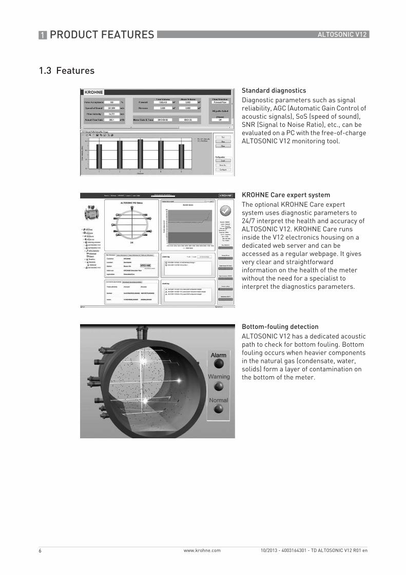
Standard diagnosticsDiagnostic parameters such as signal reliability, AGC (Automatic Gain Control of acoustic signals), SoS (speed of sound), SNR (Signal to Noise Ratio), etc., can be evaluated on a PC with the free-of-charge ALTOSONIC V12 monitoring tool.
KROHNE Care expert systemThe optional KROHNE Care expert system uses diagnostic parameters to 24/7 interpret the health and accuracy of ALTOSONIC V12. KROHNE Care runs inside the V12 electronics housing on a dedicated web server and can be accessed as a regular webpage. It gives very clear and straightforward information on the health of the meter without the need for a specialist to interpret the diagnostics parameters.
Bottom-fouling detectionALTOSONIC V12 has a dedicated acoustic path to check for bottom fouling. Bottom fouling occurs when heavier components in the natural gas (condensate, water, solids) form a layer of contamination on the bottom of the meter.
PRODUCT FEATURES 1
7
ALTOSONIC V12
www.krohne.com10/2013 - 4003164301 - TD ALTOSONIC V12 R01 en
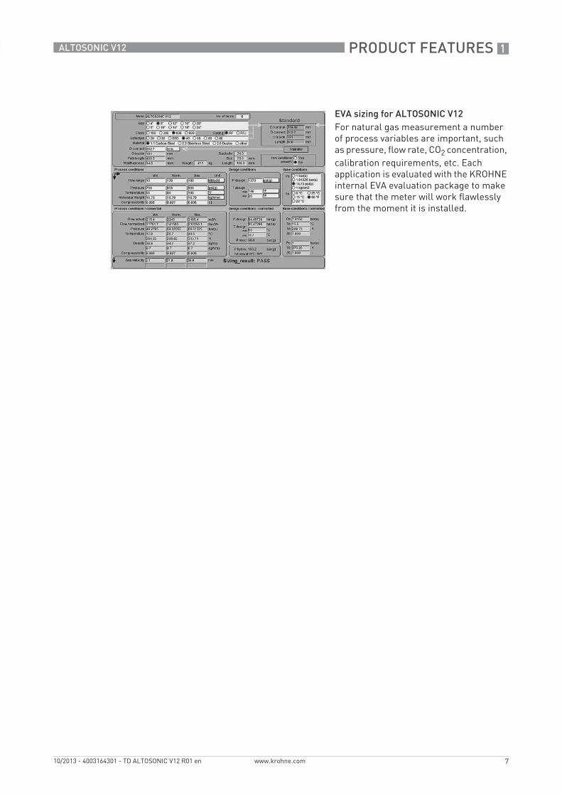
EVA sizing for ALTOSONIC V12For natural gas measurement a number of process variables are important, such as pressure, flow rate, CO2 concentration, calibration requirements, etc. Each application is evaluated with the KROHNE internal EVA evaluation package to make sure that the meter will work flawlessly from the moment it is installed.
1 PRODUCT FEATURES
8
ALTOSONIC V12
www.krohne.com 10/2013 - 4003164301 - TD ALTOSONIC V12 R01 en
1.4 Measuring principle
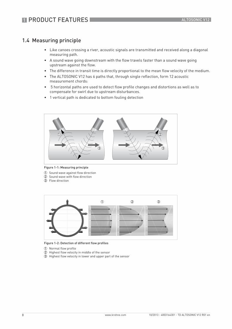
• Like canoes crossing a river, acoustic signals are transmitted and received along a diagonal measuring path.
• A sound wave going downstream with the flow travels faster than a sound wave going upstream against the flow.
• The difference in transit time is directly proportional to the mean flow velocity of the medium.• The ALTOSONIC V12 has 6 paths that, through single reflection, form 12 acoustic
measurement chords:• 5 horizontal paths are used to detect flow profile changes and distortions as well as to
compensate for swirl due to upstream disturbances.• 1 vertical path is dedicated to bottom fouling detection
Figure 1-1: Measuring principle
1 Sound wave against flow direction2 Sound wave with flow direction3 Flow direction
Figure 1-2: Detection of different flow profiles
1 Normal flow profile2 Highest flow velocity in middle of the sensor3 Highest flow velocity in lower and upper part of the sensor
TECHNICAL DATA 2
9
ALTOSONIC V12
www.krohne.com10/2013 - 4003164301 - TD ALTOSONIC V12 R01 en
2.1 Technical data table
• The following data is provided for general applications. If you require data that is more relevant to your specific application, please contact us or your local sales office.
• Additional information (certificates, special tools, software,...) and complete product documentation can be downloaded free of charge from the website (Download Center).
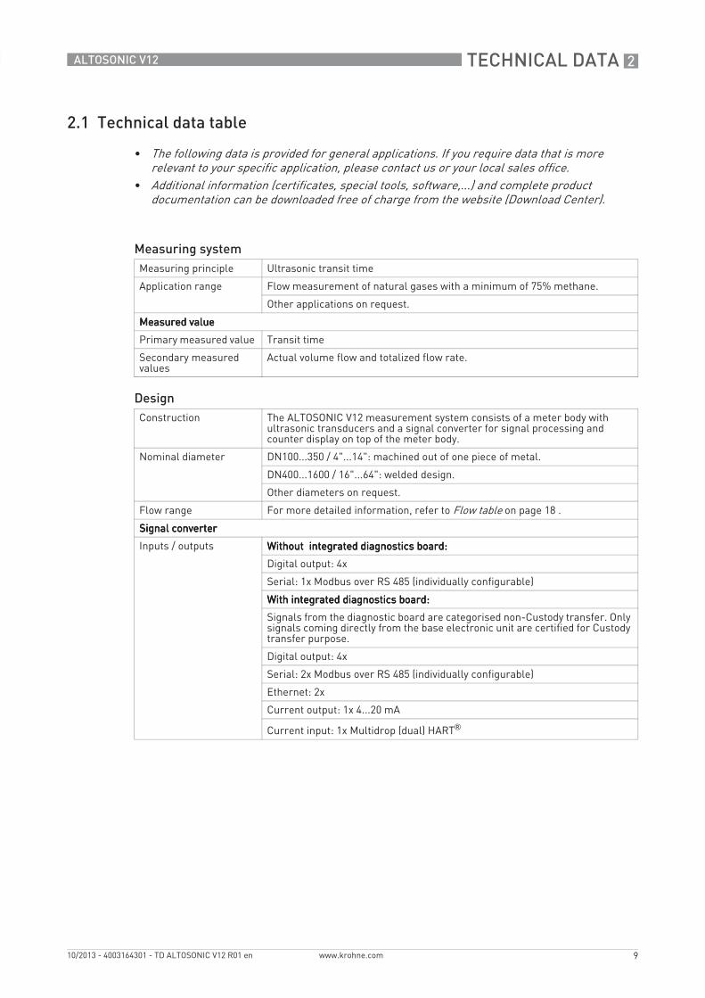
Measuring systemMeasuring principle Ultrasonic transit time
Application range Flow measurement of natural gases with a minimum of 75% methane.
Other applications on request.
Measured valueMeasured valueMeasured valueMeasured value
Primary measured value Transit time
Secondary measured values
Actual volume flow and totalized flow rate.
DesignConstruction The ALTOSONIC V12 measurement system consists of a meter body with
ultrasonic transducers and a signal converter for signal processing and counter display on top of the meter body.
Nominal diameter DN100...350 / 4"...14": machined out of one piece of metal.
DN400...1600 / 16"...64": welded design.
Other diameters on request.
Flow range For more detailed information, refer to Flow table on page 18 .
Signal converterSignal converterSignal converterSignal converter
Inputs / outputs Without integrated diagnostics board:Without integrated diagnostics board:Without integrated diagnostics board:Without integrated diagnostics board:
Digital output: 4x
Serial: 1x Modbus over RS 485 (individually configurable)
With integrated diagnostics board:With integrated diagnostics board:With integrated diagnostics board:With integrated diagnostics board:
Signals from the diagnostic board are categorised non-Custody transfer. Only signals coming directly from the base electronic unit are certified for Custody transfer purpose.
Digital output: 4x
Serial: 2x Modbus over RS 485 (individually configurable)
Ethernet: 2x
Current output: 1x 4...20 mA
Current input: 1x Multidrop (dual) HART®
2 TECHNICAL DATA
10
ALTOSONIC V12
www.krohne.com 10/2013 - 4003164301 - TD ALTOSONIC V12 R01 en
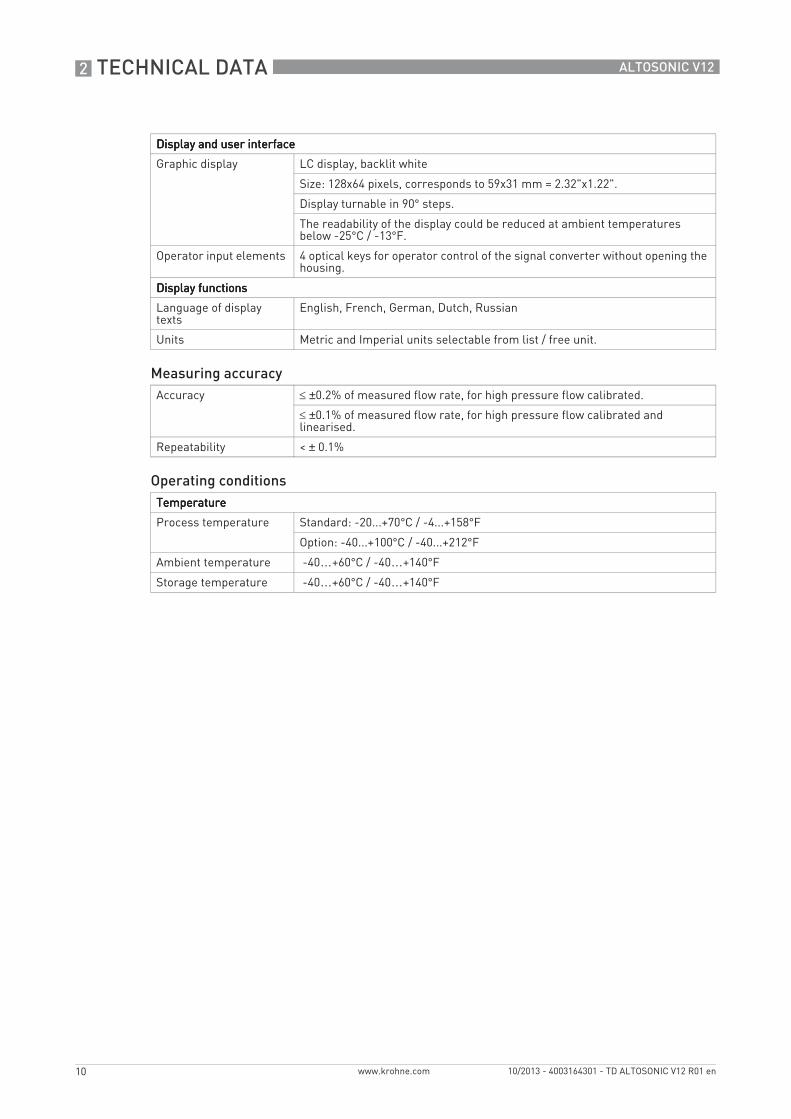
Display and user interfaceDisplay and user interfaceDisplay and user interfaceDisplay and user interface
Graphic display LC display, backlit white
Size: 128x64 pixels, corresponds to 59x31 mm = 2.32"x1.22".
Display turnable in 90° steps.
The readability of the display could be reduced at ambient temperatures below -25°C / -13°F.
Operator input elements 4 optical keys for operator control of the signal converter without opening the housing.
Display functionsDisplay functionsDisplay functionsDisplay functions
Language of display texts
English, French, German, Dutch, Russian
Units Metric and Imperial units selectable from list / free unit.
Measuring accuracyAccuracy ≤ ±0.2% of measured flow rate, for high pressure flow calibrated.
≤ ±0.1% of measured flow rate, for high pressure flow calibrated and linearised.
Repeatability < ± 0.1%
Operating conditionsTemperatureTemperatureTemperatureTemperature
Process temperature Standard: -20...+70°C / -4...+158°F
Option: -40...+100°C / -40...+212°F
Ambient temperature -40…+60°C / -40…+140°F
Storage temperature -40…+60°C / -40…+140°F
TECHNICAL DATA 2
11
ALTOSONIC V12
www.krohne.com10/2013 - 4003164301 - TD ALTOSONIC V12 R01 en
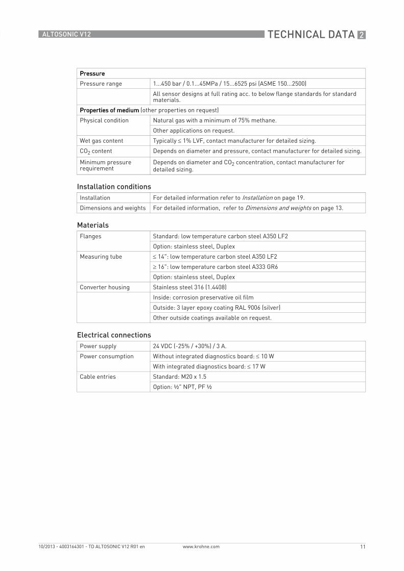
PressurePressurePressurePressure
Pressure range 1...450 bar / 0.1...45MPa / 15...6525 psi (ASME 150...2500)
All sensor designs at full rating acc. to below flange standards for standard materials.
Properties of mediumProperties of mediumProperties of mediumProperties of medium (other properties on request)
Physical condition Natural gas with a minimum of 75% methane.
Other applications on request.
Wet gas content Typically ≤ 1% LVF, contact manufacturer for detailed sizing.
CO2 content Depends on diameter and pressure, contact manufacturer for detailed sizing.
Minimum pressure requirement
Depends on diameter and CO2 concentration, contact manufacturer for detailed sizing.
Installation conditionsInstallation For detailed information refer to Installation on page 19.
Dimensions and weights For detailed information, refer to Dimensions and weights on page 13.
MaterialsFlanges Standard: low temperature carbon steel A350 LF2
Option: stainless steel, Duplex
Measuring tube ≤ 14": low temperature carbon steel A350 LF2
≥ 16": low temperature carbon steel A333 GR6
Option: stainless steel, Duplex
Converter housing Stainless steel 316 (1.4408)
Inside: corrosion preservative oil film
Outside: 3 layer epoxy coating RAL 9006 (silver)
Other outside coatings available on request.
Electrical connectionsPower supply 24 VDC (-25% / +30%) / 3 A.
Power consumption Without integrated diagnostics board: ≤ 10 W
With integrated diagnostics board: ≤ 17 W
Cable entries Standard: M20 x 1.5
Option: ½" NPT, PF ½
2 TECHNICAL DATA
12
ALTOSONIC V12
www.krohne.com 10/2013 - 4003164301 - TD ALTOSONIC V12 R01 en
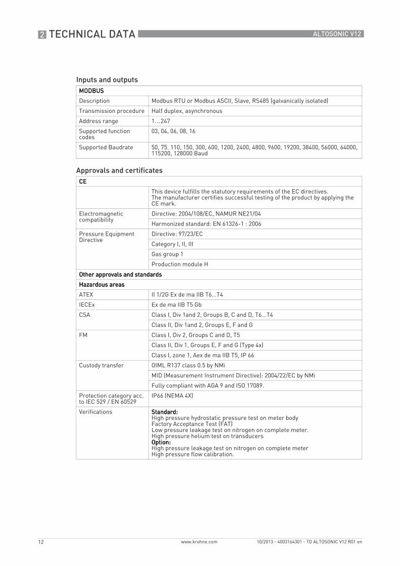
Inputs and outputsMODBUSMODBUSMODBUSMODBUS
Description Modbus RTU or Modbus ASCII, Slave, RS485 (galvanically isolated)
Transmission procedure Half duplex, asynchronous
Address range 1…247
Supported function codes
03, 04, 06, 08, 16
Supported Baudrate 50, 75. 110, 150, 300, 600, 1200, 2400, 4800, 9600, 19200, 38400, 56000, 64000, 115200, 128000 Baud
Approvals and certificatesCECECECE
This device fulfills the statutory requirements of the EC directives. The manufacturer certifies successful testing of the product by applying the CE mark.
Electromagnetic compatibility
Directive: 2004/108/EC, NAMUR NE21/04
Harmonized standard: EN 61326-1 : 2006
Pressure Equipment Directive
Directive: 97/23/EC
Category I, II, III
Gas group 1
Production module H
Other approvals and standardsOther approvals and standardsOther approvals and standardsOther approvals and standards
Hazardous areasHazardous areasHazardous areasHazardous areas
ATEX II 1/2G Ex de ma IIB T6...T4
IECEx Ex de ma IIB T5 Gb
CSA Class I, Div 1and 2, Groups B, C and D, T6...T4
Class II, Div 1and 2, Groups E, F and G
FM Class I, Div 2, Groups C and D, T5
Class II, Div 1, Groups E, F and G (Type 4x)
Class I, zone 1, Aex de ma IIB T5, IP 66
Custody transfer OIML R137 class 0.5 by NMi
MID (Measurement Instrument Directive): 2004/22/EC by NMi
Fully compliant with AGA 9 and ISO 17089.
Protection category acc. to IEC 529 / EN 60529
IP66 (NEMA 4X)
Verifications Standard:Standard:Standard:Standard:High pressure hydrostatic pressure test on meter bodyFactory Acceptance Test (FAT)Low pressure leakage test on nitrogen on complete meter.High pressure helium test on transducersOption:Option:Option:Option:High pressure leakage test on nitrogen on complete meterHigh pressure flow calibration.
TECHNICAL DATA 2
13
ALTOSONIC V12
www.krohne.com10/2013 - 4003164301 - TD ALTOSONIC V12 R01 en
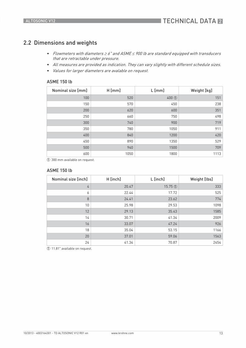
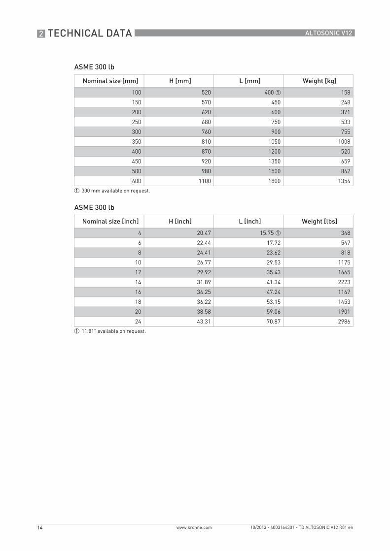
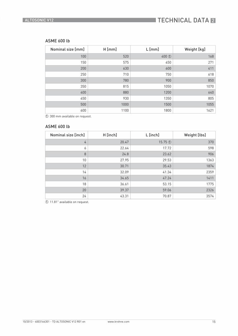
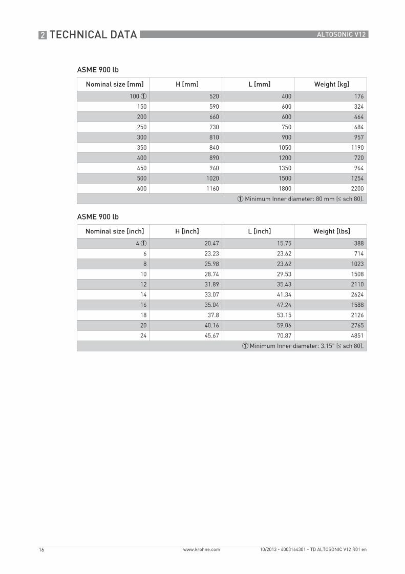
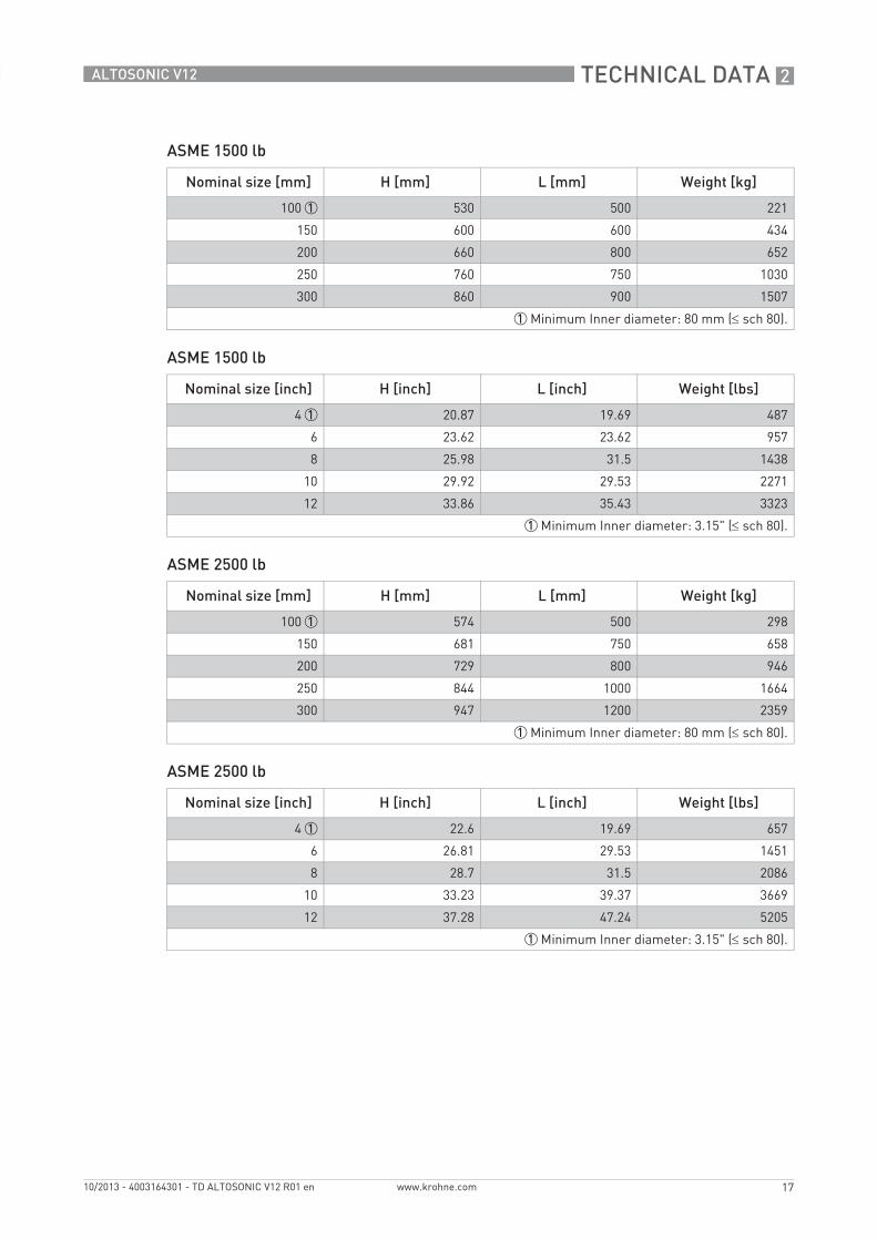
2.2 Dimensions and weights
ASME 150 lb
ASME 150 lb
• Flowmeters with diameters ≥ 6" and ASME ≤ 900 lb are standard equipped with transducers that are retractable under pressure.
• All measures are provided as indication. They can vary slightly with different schedule sizes.• Values for larger diameters are avalable on request.
Nominal size [mm] H [mm] L [mm] Weight [kg]
100 520 400 1 151
150 570 450 238
200 620 600 351
250 660 750 498
300 740 900 719
350 780 1050 911
400 840 1200 420
450 890 1350 529
500 940 1500 709
600 1050 1800 1113
1 300 mm available on request.
Nominal size [inch] H [inch] L [inch] Weight [lbs]
4 20.47 15.75 1 333
6 22.44 17.72 525
8 24.41 23.62 774
10 25.98 29.53 1098
12 29.13 35.43 1585
14 30.71 41.34 2009
16 33.07 47.24 926
18 35.04 53.15 1166
20 37.01 59.06 1563
24 41.34 70.87 2454
1 11.81" available on request.
2 TECHNICAL DATA
14
ALTOSONIC V12
www.krohne.com 10/2013 - 4003164301 - TD ALTOSONIC V12 R01 en
ASME 300 lb
ASME 300 lb
Nominal size [mm] H [mm] L [mm] Weight [kg]
100 520 400 1 158
150 570 450 248
200 620 600 371
250 680 750 533
300 760 900 755
350 810 1050 1008
400 870 1200 520
450 920 1350 659
500 980 1500 862
600 1100 1800 1354
1 300 mm available on request.
Nominal size [inch] H [inch] L [inch] Weight [lbs]
4 20.47 15.75 1 348
6 22.44 17.72 547
8 24.41 23.62 818
10 26.77 29.53 1175
12 29.92 35.43 1665
14 31.89 41.34 2223
16 34.25 47.24 1147
18 36.22 53.15 1453
20 38.58 59.06 1901
24 43.31 70.87 2986
1 11.81" available on request.
TECHNICAL DATA 2
15
ALTOSONIC V12
www.krohne.com10/2013 - 4003164301 - TD ALTOSONIC V12 R01 en
ASME 600 lb
ASME 600 lb
Nominal size [mm] H [mm] L [mm] Weight [kg]
100 520 400 1 168
150 575 450 271
200 630 600 411
250 710 750 618
300 780 900 850
350 815 1050 1070
400 880 1200 640
450 930 1350 805
500 1000 1500 1055
600 1100 1800 1621
1 300 mm available on request.
Nominal size [inch] H [inch] L [inch] Weight [lbs]
4 20.47 15.75 1 370
6 22.64 17.72 598
8 24.8 23.62 906
10 27.95 29.53 1363
12 30.71 35.43 1874
14 32.09 41.34 2359
16 34.65 47.24 1411
18 36.61 53.15 1775
20 39.37 59.06 2326
24 43.31 70.87 3574
1 11.81" available on request.
2 TECHNICAL DATA
16
ALTOSONIC V12
www.krohne.com 10/2013 - 4003164301 - TD ALTOSONIC V12 R01 en
ASME 900 lb
ASME 900 lb
Nominal size [mm] H [mm] L [mm] Weight [kg]
100 1 520 400 176
150 590 600 324
200 660 600 464
250 730 750 684
300 810 900 957
350 840 1050 1190
400 890 1200 720
450 960 1350 964
500 1020 1500 1254
600 1160 1800 2200
1 Minimum Inner diameter: 80 mm (≤ sch 80).
Nominal size [inch] H [inch] L [inch] Weight [lbs]
4 1 20.47 15.75 388
6 23.23 23.62 714
8 25.98 23.62 1023
10 28.74 29.53 1508
12 31.89 35.43 2110
14 33.07 41.34 2624
16 35.04 47.24 1588
18 37.8 53.15 2126
20 40.16 59.06 2765
24 45.67 70.87 4851
1 Minimum Inner diameter: 3.15" (≤ sch 80).
TECHNICAL DATA 2
17
ALTOSONIC V12
www.krohne.com10/2013 - 4003164301 - TD ALTOSONIC V12 R01 en
ASME 1500 lb
ASME 1500 lb
ASME 2500 lb
ASME 2500 lb
Nominal size [mm] H [mm] L [mm] Weight [kg]
100 1 530 500 221
150 600 600 434
200 660 800 652
250 760 750 1030
300 860 900 1507
1 Minimum Inner diameter: 80 mm (≤ sch 80).
Nominal size [inch] H [inch] L [inch] Weight [lbs]
4 1 20.87 19.69 487
6 23.62 23.62 957
8 25.98 31.5 1438
10 29.92 29.53 2271
12 33.86 35.43 3323
1 Minimum Inner diameter: 3.15" (≤ sch 80).
Nominal size [mm] H [mm] L [mm] Weight [kg]
100 1 574 500 298
150 681 750 658
200 729 800 946
250 844 1000 1664
300 947 1200 2359
1 Minimum Inner diameter: 80 mm (≤ sch 80).
Nominal size [inch] H [inch] L [inch] Weight [lbs]
4 1 22.6 19.69 657
6 26.81 29.53 1451
8 28.7 31.5 2086
10 33.23 39.37 3669
12 37.28 47.24 5205
1 Minimum Inner diameter: 3.15" (≤ sch 80).
2 TECHNICAL DATA
18
ALTOSONIC V12
www.krohne.com 10/2013 - 4003164301 - TD ALTOSONIC V12 R01 en
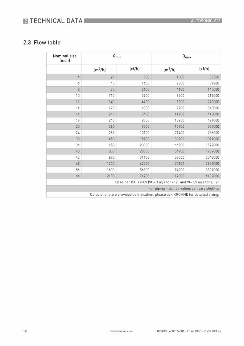
2.3 Flow table
Nominal size [inch]
Qmin Qmax
[m3/h] [cf/h] [m3/h] [cf/h]
4 25 900 1000 35300
6 45 1600 2300 81200
8 75 2600 4100 145000
10 110 3900 6200 219000
12 140 4900 8200 290000
14 170 6000 9700 343000
16 210 7400 11700 413000
18 240 8500 13900 491000
20 260 9200 15700 554000
24 285 10100 21400 756000
30 450 15900 30900 1091000
36 650 23000 44500 1572000
40 800 28300 54900 1939000
42 880 31100 58000 2048000
48 1200 42400 75800 2677000
56 1600 56500 94200 3327000
64 2100 74200 117000 4132000
Qt as per ISO 17089 (Vt = 3 m/s for <12" and Vt=1.5 m/s for ≥ 12"
For piping > Sch 80 values can vary slightly.
Calculations are provided as indication, please ask KROHNE for detailed sizing.
INSTALLATION 3
19
ALTOSONIC V12
www.krohne.com10/2013 - 4003164301 - TD ALTOSONIC V12 R01 en
3.1 Intended use
The ALTOSONIC V12 is a gas flowmeter for custody transfer applications. The meter is suitable to operate at least under the following conditions:
• relative density from 0.55 and upwards• methane concentrations 75...100%
3.2 Pre-installation requirements
3.3 Installation
3.3.1 Mounting position
Install the ultrasonic gas flowmeter in horizontal position with the flow arrow indicator on the nameplate or on the meter body in the direction of the positive (forward) gas flow.Make sure that the converter is on top of the flowmeter after the installation.Check the weight of the meter. Typically the weight of the meter will be considerably more than the same length of pipe line.
Responsibility for the use of the measuring devices with regard to suitability, intended use and corrosion resistance of the used materials against the measured fluid lies solely with the operator.
The manufacturer is not liable for any damage resulting from improper use or use for other than the intended purpose.
High levels of CO2 can inhibit the operation of an ultrasonic flowmeter due to its acoustic absorption properties. It is recommended to submit a specification of the process medium to be measured at the manufacturer for advice.
The equipment is designed for safe operation under conditions according to the following classifications:• Pollution degree 2: this means that normally only nonconductive (dry) pollution will occur.
Temporary conductivity caused by condensation can occur.• Protection class I: this means the equipment must be earthed.• Humidity: <95% RH• Ambient temperature: -40...+65°C / -40...+149°F• Suitable for indoor and outdoor use.• IP66 / NEMA 4X classification.
The flowmeter should be protected from corrosive chemicals or gases and dust or particles accumulation.
Do not intend to perform a hydrostatic test of the installed flowmeter.
The flowmeter has been hydrostatically tested during manufacturing (see reports) and must not be retested with the ultrasonic sensors installed. Water will protude in the sensor pockets and remain. This will create acoustic shortcuts and possibly cause the flowmeter to start operating in failure.
3 INSTALLATION
20
ALTOSONIC V12
www.krohne.com 10/2013 - 4003164301 - TD ALTOSONIC V12 R01 en
To support the meter additional supports might be needed, preferably two, one on either side of the meter.Always support the meter at its flanges, the weight of the meter shall never rest on the case around the transducers and the cabling.If supports can not be placed under the meter flanges, supports may be placed under the mating flanges of the pipeline. If supports can only be placed under the pipeline sections upstream or downstream of the meter, these supports shall be as close as possible to the meter. In this case a calculation must be made to verify that the load on the pipeline will not exceed acceptable values.The meter should be installed in the pipe line with gaskets, nuts and bolts according to the type and size of the flanges of the gas flowmeter. The flanges of the meter should match with the flanges of the pipeline where the meter should be installed.
Make sure that the gaskets do not protude into the flow as this can reduce the accuracy of the flowmeter.In order to install the gas flowmeter, the pipeline must have a slot of such length that the meter including the gaskets fits nicely in the slot. It should not be necessary to use excessive force to tighten the bolts in order to close the gaps on either side of the meter. Nor should the slot be too small, implying the slot has to be widened by applying brute force to fit the meter and gaskets in the slot.For tightening the bolts of the flanges, apply a lubricant as required, in accordance with the materials as used and applicable standards.Tighten the bolts of the flanges with a torque according to the standards applicable to the flanges and materials used.
3.3.2 Pipe diameters and lengths
Make sure that the inner diameter of upstream and downstream pipes matches the specified connection diameter of the ultrasonic flowmeter within 1%. Contact the manufacturer if the inner diameter deviates more than 1%.
3.3.3 Flow conditioners
Although the flowmeter is a highly accurate device, an additional flow conditioner can be installed upstream of the flowmeter in order to minimize measuring uncertainty, in particular when a strongly distorted flow velocity profile is expected, or when the available space for a metering run is critical. If a flow conditioner is used the total inlet length may be reduced to only 5 DN: having 2 DN upstream of the flow conditioner and 3 DN in between the flow conditioner and the flowmeter.
• Preferred model is the “perforated plate” type. A “pipe bundle” type of flow conditioner is not recommended.
• When a flow conditioner is included in the metering run, it is strongly advised to use the same flow conditioner and inlet pipe configuration during a flow (wet) calibration (see e.g. ISO 17089 or AGA-9 for detailed requirements).
INSTALLATION 3
21
ALTOSONIC V12
www.krohne.com10/2013 - 4003164301 - TD ALTOSONIC V12 R01 en
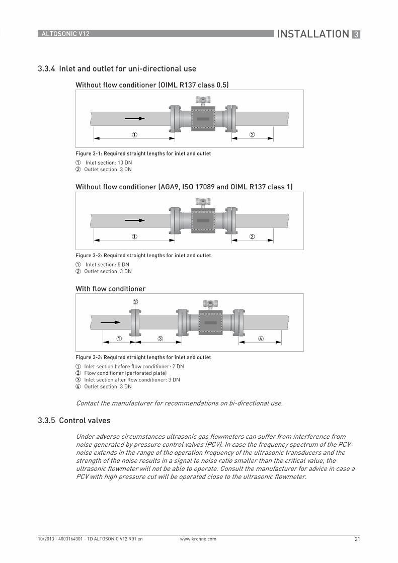
3.3.4 Inlet and outlet for uni-directional use
3.3.5 Control valves
Without flow conditioner (OIML R137 class 0.5)
Figure 3-1: Required straight lengths for inlet and outlet
1 Inlet section: 10 DN2 Outlet section: 3 DN
Without flow conditioner (AGA9, ISO 17089 and OIML R137 class 1)
Figure 3-2: Required straight lengths for inlet and outlet
1 Inlet section: 5 DN2 Outlet section: 3 DN
With flow conditioner
Figure 3-3: Required straight lengths for inlet and outlet
1 Inlet section before flow conditioner: 2 DN2 Flow conditioner (perforated plate)3 Inlet section after flow conditioner: 3 DN4 Outlet section: 3 DN
Contact the manufacturer for recommendations on bi-directional use.
Under adverse circumstances ultrasonic gas flowmeters can suffer from interference from noise generated by pressure control valves (PCV). In case the frequency spectrum of the PCV-noise extends in the range of the operation frequency of the ultrasonic transducers and the strength of the noise results in a signal to noise ratio smaller than the critical value, the ultrasonic flowmeter will not be able to operate. Consult the manufacturer for advice in case a PCV with high pressure cut will be operated close to the ultrasonic flowmeter.
3 INSTALLATION
22
ALTOSONIC V12
www.krohne.com 10/2013 - 4003164301 - TD ALTOSONIC V12 R01 en
3.3.6 P and T sensors
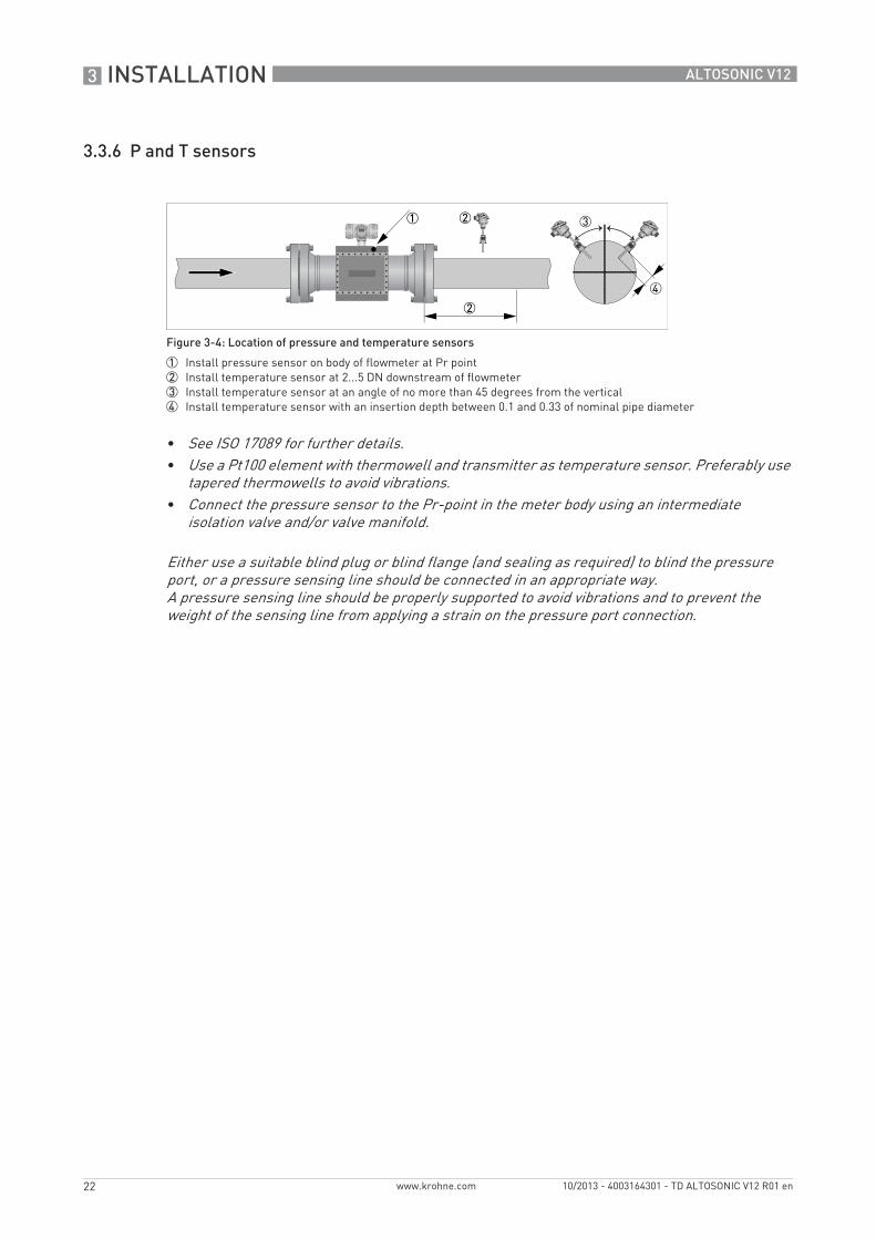
Figure 3-4: Location of pressure and temperature sensors
1 Install pressure sensor on body of flowmeter at Pr point2 Install temperature sensor at 2...5 DN downstream of flowmeter3 Install temperature sensor at an angle of no more than 45 degrees from the vertical4 Install temperature sensor with an insertion depth between 0.1 and 0.33 of nominal pipe diameter
• See ISO 17089 for further details.• Use a Pt100 element with thermowell and transmitter as temperature sensor. Preferably use
tapered thermowells to avoid vibrations.• Connect the pressure sensor to the Pr-point in the meter body using an intermediate
isolation valve and/or valve manifold.
Either use a suitable blind plug or blind flange (and sealing as required) to blind the pressure port, or a pressure sensing line should be connected in an appropriate way. A pressure sensing line should be properly supported to avoid vibrations and to prevent the weight of the sensing line from applying a strain on the pressure port connection.
INSTALLATION 3
23
ALTOSONIC V12
www.krohne.com10/2013 - 4003164301 - TD ALTOSONIC V12 R01 en
3.4 Temperatures
For more detailed information about temperatures, refer to Technical data table on page 9.
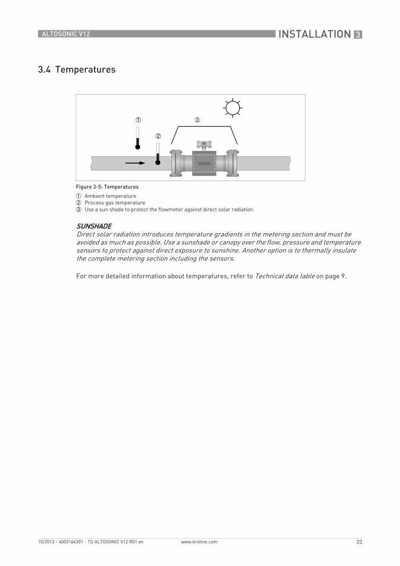
Figure 3-5: Temperatures
1 Ambient temperature2 Process gas temperature3 Use a sun shade to protect the flowmeter against direct solar radiation.
SUNSHADESUNSHADESUNSHADESUNSHADEDirect solar radiation introduces temperature gradients in the metering section and must be avoided as much as possible. Use a sunshade or canopy over the flow, pressure and temperature sensors to protect against direct exposure to sunshine. Another option is to thermally insulate the complete metering section including the sensors.
4 ELECTRICAL CONNECTIONS
24
ALTOSONIC V12
www.krohne.com 10/2013 - 4003164301 - TD ALTOSONIC V12 R01 en
4.1 Safety instructions
4.2 Digital I/O connections
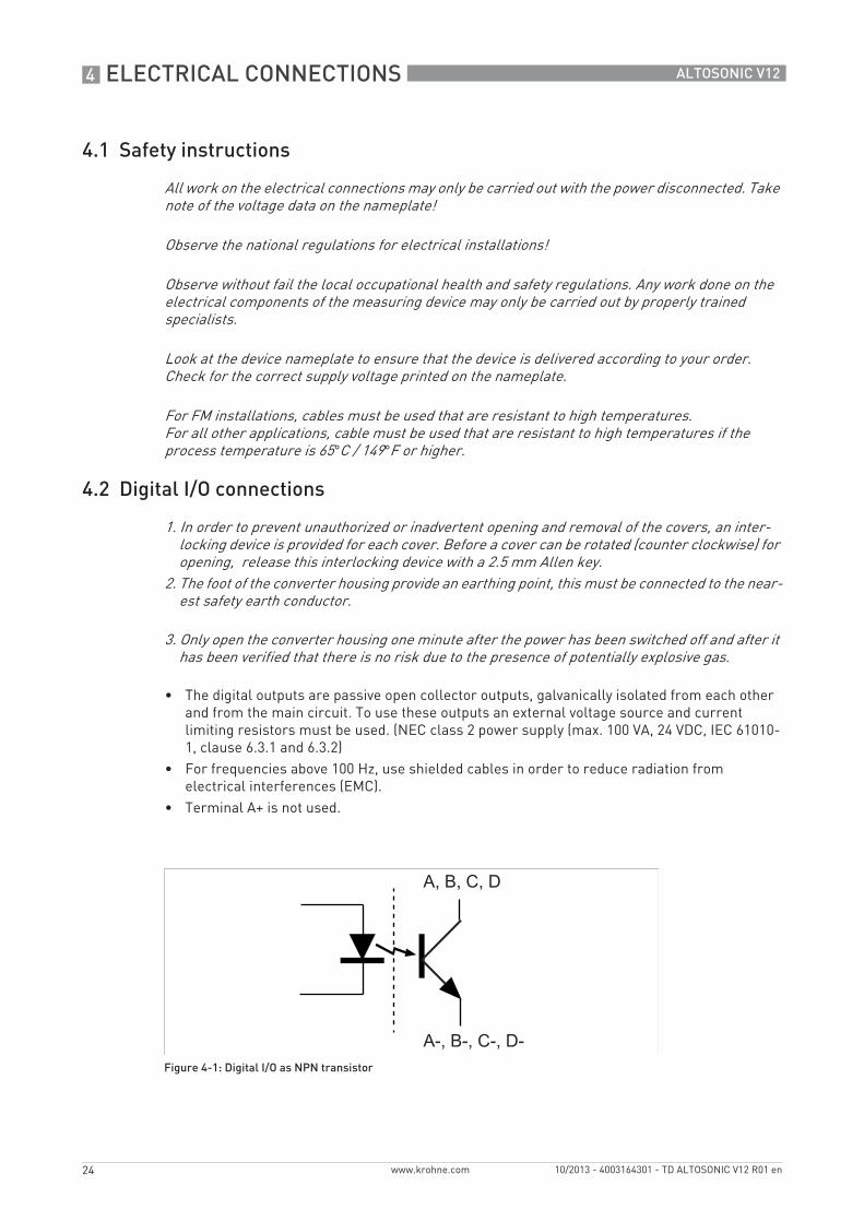
• The digital outputs are passive open collector outputs, galvanically isolated from each other and from the main circuit. To use these outputs an external voltage source and current limiting resistors must be used. (NEC class 2 power supply (max. 100 VA, 24 VDC, IEC 61010-1, clause 6.3.1 and 6.3.2)
• For frequencies above 100 Hz, use shielded cables in order to reduce radiation from electrical interferences (EMC).
• Terminal A+ is not used.
All work on the electrical connections may only be carried out with the power disconnected. Take note of the voltage data on the nameplate!
Observe the national regulations for electrical installations!
Observe without fail the local occupational health and safety regulations. Any work done on the electrical components of the measuring device may only be carried out by properly trained specialists.
Look at the device nameplate to ensure that the device is delivered according to your order. Check for the correct supply voltage printed on the nameplate.
For FM installations, cables must be used that are resistant to high temperatures. For all other applications, cable must be used that are resistant to high temperatures if the process temperature is 65°C / 149°F or higher.
1. In order to prevent unauthorized or inadvertent opening and removal of the covers, an inter-locking device is provided for each cover. Before a cover can be rotated (counter clockwise) for opening, release this interlocking device with a 2.5 mm Allen key.
2. The foot of the converter housing provide an earthing point, this must be connected to the near-est safety earth conductor.
3. Only open the converter housing one minute after the power has been switched off and after it has been verified that there is no risk due to the presence of potentially explosive gas.
Figure 4-1: Digital I/O as NPN transistor
ELECTRICAL CONNECTIONS 4
25
ALTOSONIC V12
www.krohne.com10/2013 - 4003164301 - TD ALTOSONIC V12 R01 en
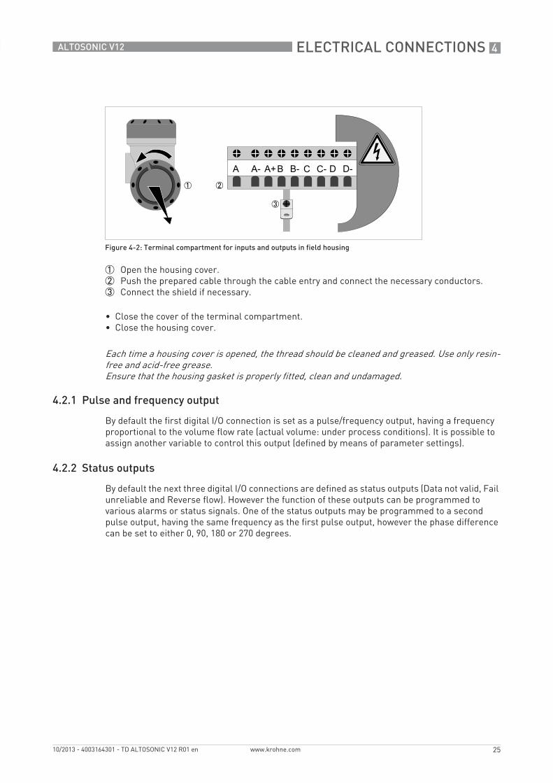
1 Open the housing cover.2 Push the prepared cable through the cable entry and connect the necessary conductors.3 Connect the shield if necessary.
• Close the cover of the terminal compartment.• Close the housing cover.
4.2.1 Pulse and frequency output
By default the first digital I/O connection is set as a pulse/frequency output, having a frequency proportional to the volume flow rate (actual volume: under process conditions). It is possible to assign another variable to control this output (defined by means of parameter settings).
4.2.2 Status outputs
By default the next three digital I/O connections are defined as status outputs (Data not valid, Fail unreliable and Reverse flow). However the function of these outputs can be programmed to various alarms or status signals. One of the status outputs may be programmed to a second pulse output, having the same frequency as the first pulse output, however the phase difference can be set to either 0, 90, 180 or 270 degrees.
Figure 4-2: Terminal compartment for inputs and outputs in field housing
Each time a housing cover is opened, the thread should be cleaned and greased. Use only resin-free and acid-free grease.Ensure that the housing gasket is properly fitted, clean and undamaged.
4 ELECTRICAL CONNECTIONS
26
ALTOSONIC V12
www.krohne.com 10/2013 - 4003164301 - TD ALTOSONIC V12 R01 en
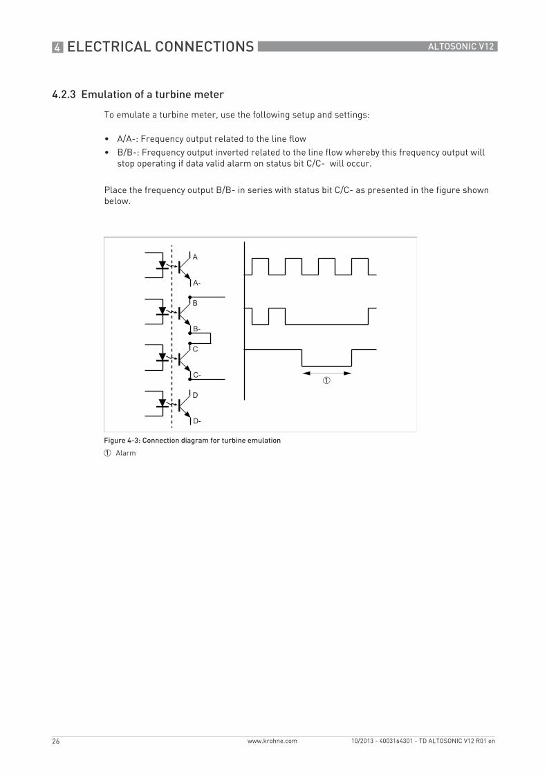
4.2.3 Emulation of a turbine meter
To emulate a turbine meter, use the following setup and settings:
• A/A-: Frequency output related to the line flow• B/B-: Frequency output inverted related to the line flow whereby this frequency output will
stop operating if data valid alarm on status bit C/C- will occur.
Place the frequency output B/B- in series with status bit C/C- as presented in the figure shown below.
Figure 4-3: Connection diagram for turbine emulation
1 Alarm
ELECTRICAL CONNECTIONS 4
27
ALTOSONIC V12
www.krohne.com10/2013 - 4003164301 - TD ALTOSONIC V12 R01 en
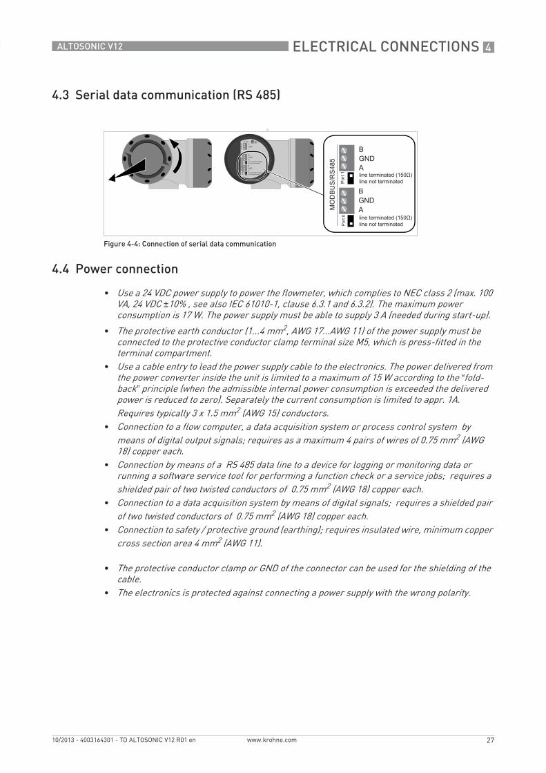
4.3 Serial data communication (RS 485)
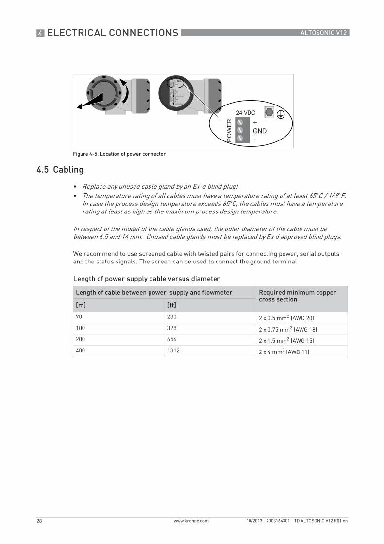
4.4 Power connection
Figure 4-4: Connection of serial data communication
• Use a 24 VDC power supply to power the flowmeter, which complies to NEC class 2 (max. 100 VA, 24 VDC ±10% , see also IEC 61010-1, clause 6.3.1 and 6.3.2). The maximum power consumption is 17 W. The power supply must be able to supply 3 A (needed during start-up).
• The protective earth conductor (1...4 mm2, AWG 17...AWG 11) of the power supply must be connected to the protective conductor clamp terminal size M5, which is press-fitted in the terminal compartment.
• Use a cable entry to lead the power supply cable to the electronics. The power delivered from the power converter inside the unit is limited to a maximum of 15 W according to the “fold-back” principle (when the admissible internal power consumption is exceeded the delivered power is reduced to zero). Separately the current consumption is limited to appr. 1A. Requires typically 3 x 1.5 mm2 (AWG 15) conductors.
• Connection to a flow computer, a data acquisition system or process control system by means of digital output signals; requires as a maximum 4 pairs of wires of 0.75 mm2 (AWG 18) copper each.
• Connection by means of a RS 485 data line to a device for logging or monitoring data or running a software service tool for performing a function check or a service jobs; requires a shielded pair of two twisted conductors of 0.75 mm2 (AWG 18) copper each.
• Connection to a data acquisition system by means of digital signals; requires a shielded pair of two twisted conductors of 0.75 mm2 (AWG 18) copper each.
• Connection to safety / protective ground (earthing); requires insulated wire, minimum copper cross section area 4 mm2 (AWG 11).
• The protective conductor clamp or GND of the connector can be used for the shielding of the cable.
• The electronics is protected against connecting a power supply with the wrong polarity.
4 ELECTRICAL CONNECTIONS
28
ALTOSONIC V12
www.krohne.com 10/2013 - 4003164301 - TD ALTOSONIC V12 R01 en
4.5 Cabling
We recommend to use screened cable with twisted pairs for connecting power, serial outputs and the status signals. The screen can be used to connect the ground terminal.
Length of power supply cable versus diameter
Figure 4-5: Location of power connector
• Replace any unused cable gland by an Ex-d blind plug! • The temperature rating of all cables must have a temperature rating of at least 65°C / 149°F.
In case the process design temperature exceeds 65°C, the cables must have a temperature rating at least as high as the maximum process design temperature.
In respect of the model of the cable glands used, the outer diameter of the cable must be between 6.5 and 14 mm. Unused cable glands must be replaced by Ex d approved blind plugs.
Length of cable between power supply and flowmeter Required minimum copper cross section
[m] [ft]
70 230 2 x 0.5 mm2 (AWG 20)
100 328 2 x 0.75 mm2 (AWG 18)
200 656 2 x 1.5 mm2 (AWG 15)
400 1312 2 x 4 mm2 (AWG 11)
ELECTRICAL CONNECTIONS 4
29
ALTOSONIC V12
www.krohne.com10/2013 - 4003164301 - TD ALTOSONIC V12 R01 en
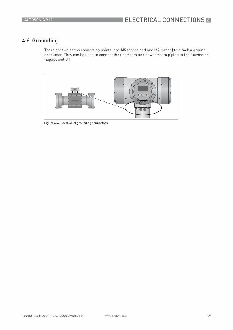
4.6 Grounding
There are two screw connection points (one M5 thread and one M4 thread) to attach a ground conductor. They can be used to connect the upstream and downstream piping to the flowmeter (Equipotential).
Figure 4-6: Location of grounding connectors
5 APPLICATIONS
30
ALTOSONIC V12
www.krohne.com 10/2013 - 4003164301 - TD ALTOSONIC V12 R01 en
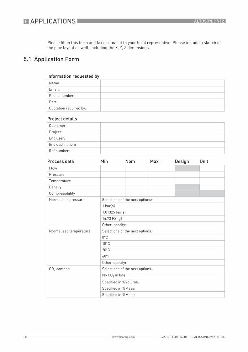
Please fill in this form and fax or email it to your local representive. Please include a sketch of the pipe layout as well, including the X, Y, Z dimensions.
5.1 Application Form
Information requested byName:
Email:
Phone number:
Date:
Quotation required by:
Project detailsCustomer:
Project:
End user:
End destination:
Ref number:
Process data Min Nom Max Design UnitFlow
Pressure
Temperature
Density
Compressibility
Normalised pressure Select one of the next options:
1 bar(a)
1.01325 bar(a)
14.73 PSI(g)
Other, specify:
Normalised temperature Select one of the next options:
0°C
15°C
20°C
60°F
Other, specify:
CO2 content: Select one of the next options:
No CO2 in line
Specified in %Volume:
Specified in %Mass:
Specified in %Mole:
APPLICATIONS 5
31
ALTOSONIC V12
www.krohne.com10/2013 - 4003164301 - TD ALTOSONIC V12 R01 en
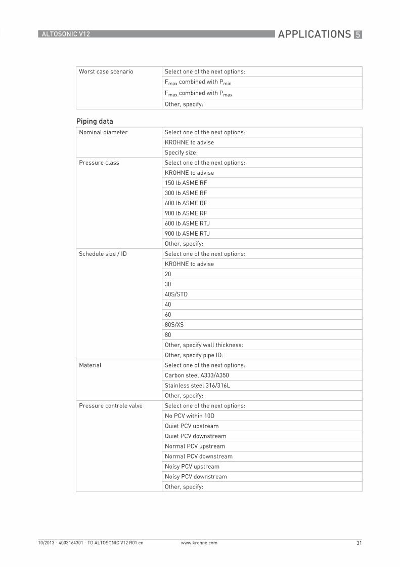
Worst case scenario Select one of the next options:
Fmax combined with Pmin
Fmax combined with Pmax
Other, specify:
Piping dataNominal diameter Select one of the next options:
KROHNE to advise
Specify size:
Pressure class Select one of the next options:
KROHNE to advise
150 lb ASME RF
300 lb ASME RF
600 lb ASME RF
900 lb ASME RF
600 lb ASME RTJ
900 lb ASME RTJ
Other, specify:
Schedule size / ID Select one of the next options:
KROHNE to advise
20
30
40S/STD
40
60
80S/XS
80
Other, specify wall thickness:
Other, specify pipe ID:
Material Select one of the next options:
Carbon steel A333/A350
Stainless steel 316/316L
Other, specify:
Pressure controle valve Select one of the next options:
No PCV within 10D
Quiet PCV upstream
Quiet PCV downstream
Normal PCV upstream
Normal PCV downstream
Noisy PCV upstream
Noisy PCV downstream
Other, specify:
5 APPLICATIONS
32
ALTOSONIC V12
www.krohne.com 10/2013 - 4003164301 - TD ALTOSONIC V12 R01 en
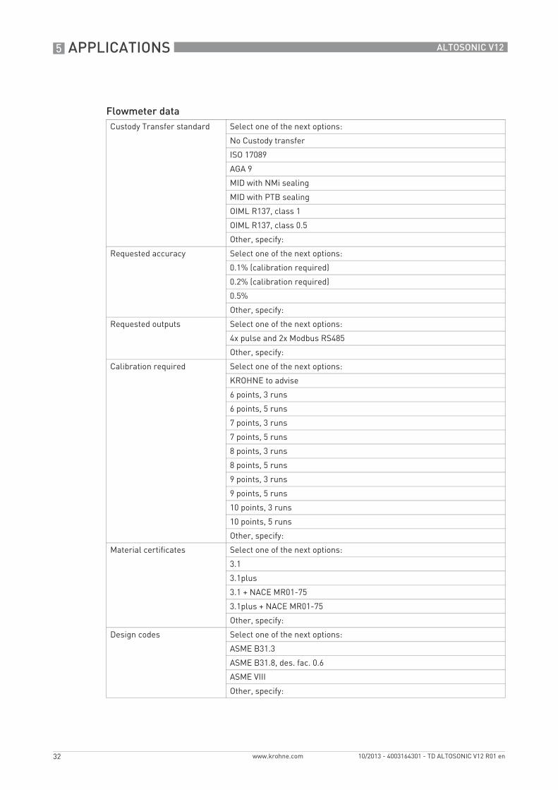
Flowmeter dataCustody Transfer standard Select one of the next options:
No Custody transfer
ISO 17089
AGA 9
MID with NMi sealing
MID with PTB sealing
OIML R137, class 1
OIML R137, class 0.5
Other, specify:
Requested accuracy Select one of the next options:
0.1% (calibration required)
0.2% (calibration required)
0.5%
Other, specify:
Requested outputs Select one of the next options:
4x pulse and 2x Modbus RS485
Other, specify:
Calibration required Select one of the next options:
KROHNE to advise
6 points, 3 runs
6 points, 5 runs
7 points, 3 runs
7 points, 5 runs
8 points, 3 runs
8 points, 5 runs
9 points, 3 runs
9 points, 5 runs
10 points, 3 runs
10 points, 5 runs
Other, specify:
Material certificates Select one of the next options:
3.1
3.1plus
3.1 + NACE MR01-75
3.1plus + NACE MR01-75
Other, specify:
Design codes Select one of the next options:
ASME B31.3
ASME B31.8, des. fac. 0.6
ASME VIII
Other, specify:
APPLICATIONS 5
33
ALTOSONIC V12
www.krohne.com10/2013 - 4003164301 - TD ALTOSONIC V12 R01 en
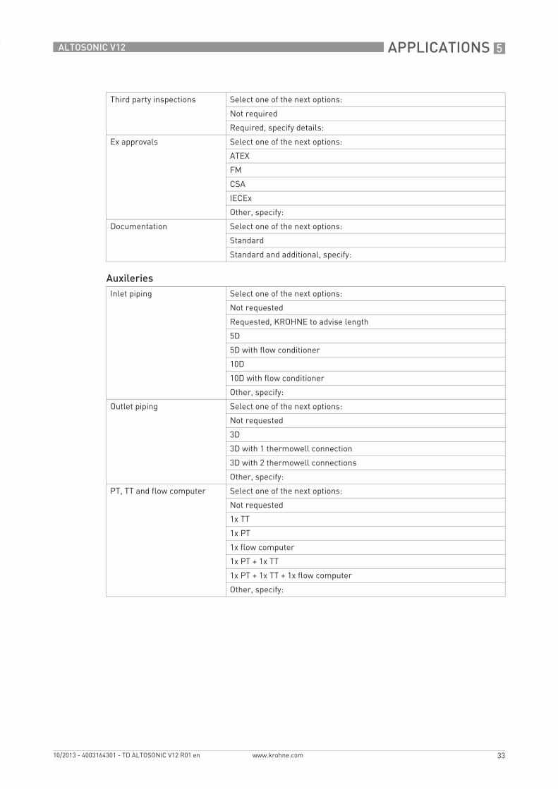
Third party inspections Select one of the next options:
Not required
Required, specify details:
Ex approvals Select one of the next options:
ATEX
FM
CSA
IECEx
Other, specify:
Documentation Select one of the next options:
Standard
Standard and additional, specify:
AuxileriesInlet piping Select one of the next options:
Not requested
Requested, KROHNE to advise length
5D
5D with flow conditioner
10D
10D with flow conditioner
Other, specify:
Outlet piping Select one of the next options:
Not requested
3D
3D with 1 thermowell connection
3D with 2 thermowell connections
Other, specify:
PT, TT and flow computer Select one of the next options:
Not requested
1x TT
1x PT
1x flow computer
1x PT + 1x TT
1x PT + 1x TT + 1x flow computer
Other, specify:
5 APPLICATIONS
34
ALTOSONIC V12
www.krohne.com 10/2013 - 4003164301 - TD ALTOSONIC V12 R01 en
OtherRemarks Specify other important information here:
More information www.krohne.com/oilandgas

NOTES 6
35
ALTOSONIC V12
www.krohne.com10/2013 - 4003164301 - TD ALTOSONIC V12 R01 en
KROHNE product overview
• Electromagnetic flowmeters
• Variable area flowmeters
• Ultrasonic flowmeters
• Mass flowmeters
• Vortex flowmeters
• Flow controllers
• Level meters
• Temperature meters
• Pressure meters
• Analysis products
• Products and systems for the oil & gas industry
• Measuring systems for the marine industry
Head Office KROHNE Messtechnik GmbHLudwig-Krohne-Str. 547058 Duisburg (Germany)Tel.:+49 (0)203 301 0Fax:+49 (0)203 301 10389 [email protected]
© K
RO
HN
E 10
/201
3 -
4003
1643
01 -
TD
ALT
OSO
NIC
V12
R01
en
- Su
bjec
t to
chan
ge w
ithou
t not
ice.
The current list of all KROHNE contacts and addresses can be found at:www.krohne.com
KK
K