Embed Size (px)
Citation preview
Ultracataclasis, sintering, and frictional melting inpseudotachylytes from East Greenland
Daniel Curewitz*, Je�rey A. Karson
Division of Earth and Ocean Sciences, Duke University, Durham, NC 27708-0229, USA
Received 9 July 1998; accepted 8 June 1999
Abstract
Large volumes of pseudotachylyte (an intrusive, fault-related rock interpreted to form by a combination of cataclasis and
melting) occur in Tertiary normal faults and accommodation zones along 0400 km of the East Greenland volcanic riftedmargin. Analysis of representative pseudotachylyte samples reveals a wide range of mesoscopic and microscopic textures,mineralogies, and chemistries in the aphanitic pseudotachylyte matrix. Three distinct types of pseudotachylyte (referred to as
angular, rounded and glassy) are identi®ed based on these characteristics. Angular pseudotachylyte (found primarily in dike-likereservoir zones) is characterized by angular grains visible on all scales, with micron-scale fragments of mica and amphibole. Itsmatrix is enriched in Fe2O3, MgO, and TiO2 relative to the host rock, with minor increases in CaO, K2O, and small decreases in
Na2O. Rounded pseudotachylyte is found in reservoir zones, injection veins (pseudotachylyte-®lled extension fractures), andfault veins (small faults with pseudotachylyte along their surfaces). It is characterized by smooth-surfaced, compacted grains onmicroscopic scales, and encloses rounded, interpenetrative lithic clasts on outcrop scale. Its matrix is enriched in Fe2O3, MgO,
TiO2, and Al2O3 relative to the host rock, with minor depletion in Na2O and K2O. Glassy pseudotachylyte is found primarilyalong fault surfaces. Its matrix is characterized by isotropic, conchoidally fractured material containing microscopic, strain-freeamphibole phenocrysts, and is enriched in TiO2, Al2O3, K2O, Fe2O3, MgO, CaO, and Na2O relative to the host rock. Theseobservations suggest that angular pseudotachylyte was produced by cataclasis, with enrichment in metallic oxides resulting from
preferential crushing of mechanically weak amphibole and mica minerals found in the gneissic host rock. Cataclasis andconcomitant frictional heating resulted in the textural and chemical modi®cation of angular pseudotachylyte by sintering ormelting, producing rounded and glassy pseudotachylyte, respectively. Compositional and textural observations constrain the
temperatures reached during frictional heating (700±9008C) which in turn delimit the amount of frictional heat imparted to thepseudotachylytes during slip. Our results suggest that the East Greenland pseudotachylytes formed during small seismic eventsalong faults at shallow crustal levels. Consistent relative ages and widespread occurrence of pseudotachylyte-bearing faults in
East Greenland suggest that widespread microseismicity accompanied the early development of this volcanic riftedmargin. # 1999 Elsevier Science Ltd. All rights reserved.
1. Introduction
Pseudotachylytes are fault rocks consisting of vary-
ing proportions of rounded to angular clasts of
country rock surrounded by dark-colored, aphanitic
matrix and generally intruding the surrounding host
rocks. Pseudotachylyte occurs along thrust, strike-slip,
and normal faults (McKenzie and Brune, 1972;
Sibson, 1975; Magloughlin and Spray, 1992; Swanson,1992; Spray, 1995), along major uncon®ned `super-faults' (Spray, 1997), in meteorite impact structures(Lambert, 1981; Dressler, 1984; Reimold, 1991;Magloughlin and Spray, 1992; Reimold and Colliston,1994; Spray and Thompson, 1995; Spray, 1997), andalong the base of major landslides (Scott and Drever,1953; Erismann, 1979; Masch et al., 1985). Frictionalmelts have been produced in experiments, duringindustrial drilling, and in quarrying operations (Spray,1987, 1989, 1992, 1995; Kennedy and Spray, 1992).The diversity of pseudotachylyte textures and settings
Journal of Structural Geology 21 (1999) 1693±1713
0191-8141/99/$ - see front matter # 1999 Elsevier Science Ltd. All rights reserved.
PII: S0191-8141(99 )00119 -4
www.elsevier.nl/locate/jstrugeo
* Corresponding author.
E-mail address: [email protected] (D. Curewitz)
has fostered disagreement over their origin and for-mation mechanism(s) (e.g. Sibson, 1975; Wenk, 1978;Shimamoto and Nagahama, 1992; Spray, 1995).Recent ®eld, laboratory and experimental investi-gations have shown that `pseudotachylyte' can beviewed as an umbrella term, covering a range of tex-tures from ultracataclasite to melt formed by a combi-nation of comminution and frictional heating duringfaulting at seismic slip rates (>10ÿ1 m sÿ1)(Magloughlin and Spray, 1992; Spray, 1995).
This paper concerns an investigation of pseudota-chylyte found in Early Tertiary normal faults and ac-commodation zones along 0400 km of the EastGreenland coast. An endogenic tectonic origin forthese pseudotachylytes (rather than association withimpact structures, e.g. Lambert, 1981; Thompson andSpray, 1994; Spray, 1997) is clearly indicated by theiroccurrence within Tertiary-age rift-related fault zones.Pseudotachylytes occur in a variety of mesoscopic set-tings within these fault zonesÐin >10-m-wide dike-like bodies (`reservoir zones'), in extension fractures(`injection veins'), and along fault surfaces (`faultveins'). Microscopic and chemical analyses of pseudo-tachylytes and host rocks from these structural settingsreveal three textures: (1) angular ultracataclasite foundmainly in reservoir zones; (2) rounded pseudotachylytefound in reservoir zones, injection veins, and faultveins; and (3) glassy pseudotachylyte found mainly infault veins. All of these are enriched in metallic oxidesrelative to their host rocks. These relationships suggesta textural evolution of pseudotachylyte as a result ofseismic slip and frictional heating. Initially, ultracata-clasite that is preferentially enriched in relatively weakma®c minerals (amphibole and mica) forms by asperitygrinding and comminution. Preferential inclusion ofma®c minerals in this ultracataclasite controls themetal oxide enrichment found in the other texturaltypes, and noted in many pseudotachylyte studies (e.g.Magloughlin and Spray, 1992). The ultracataclasite issubsequently modi®ed to varying degrees by frictionalheating, either by sintering (densi®cation of granularmaterial by solution transfer processes at elevated tem-peratures, e.g. Luan and Patterson, 1992) or melting.Interpretation of the structural settings, textures, andchemistries of these pseudotachylytes suggests thatthey formed during relatively low-magnitude earth-quakes that may have accompanied Early Tertiarycontinental rifting in East Greenland.
2. Geologic setting
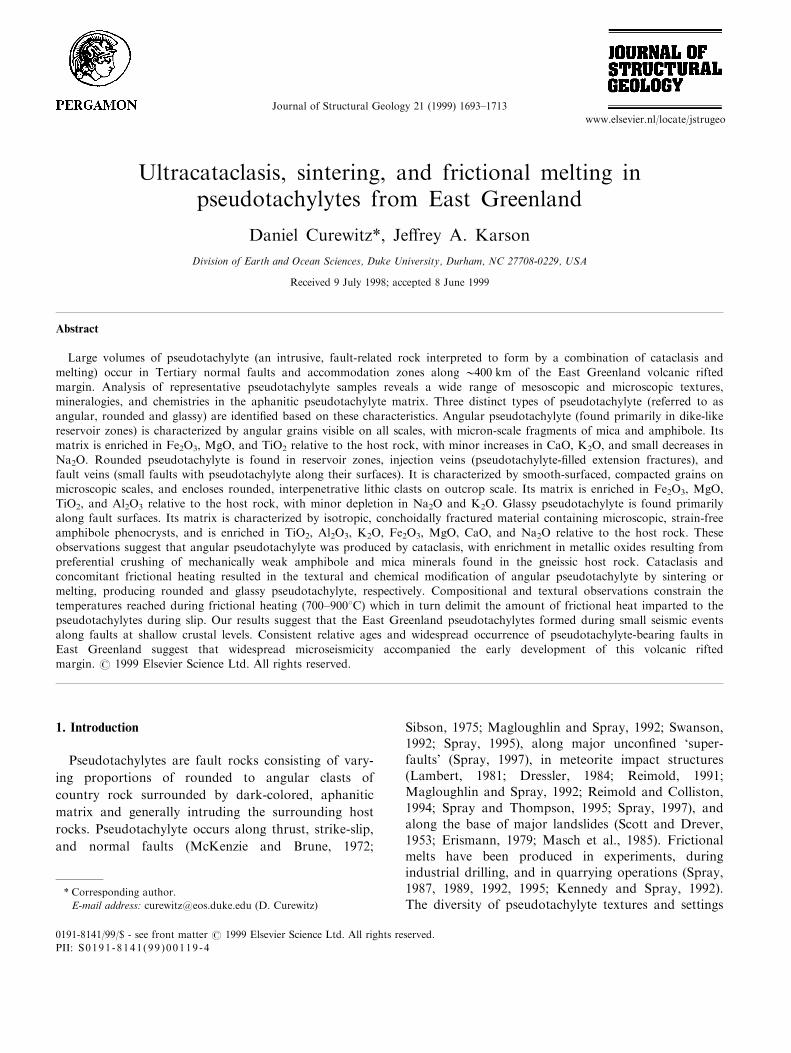
East Greenland was separated from Scandinavia andWestern Europe in the Early Tertiary, forming therifted margins that now bound the northeast Atlantic(Brooks and Nielsen, 1982; Larsen, 1990; Eldholm and
Grue, 1994). Fieldwork for this study was conducted
along the coast of East Greenland south of
Kangerlussuaq Fjord (Fig. 1). The study area has
undergone 06 km of uplift in the Tertiary (Gleadow
and Brooks, 1979; Brooks and Nielsen, 1982; Hansen,
1996). Uplift and erosion have exposed basement com-
posed of Archean±Proterozoic granitic gneiss with up
to 100-m-wide amphibolite bands (Bridgewater et al.,
1976). Local Cretaceous±Tertiary sedimentary depos-
its, a coast-parallel dike swarm, extensive (>5 km
thick) ¯ood basalts, and several ma®c and silicic intru-
sions characterize the general geology of the East
Greenland volcanic rifted margin in this area (Nielsen,
1975, 1978; Brooks and Nielsen, 1982; Pedersen et al.,
1997; Karson et al., 1998; Karson and Brooks, 1999).
Fig. 1. Geological map of study areas in East Greenland. (a)
Location map of Greenland: S=Skjoldungen, K=Kangerlussuaq
Fjord, SS=Scoresby Sund. (b) Highly generalized map of the study
areas south of Kangerlussuaq Fjord, sample sites marked by ®lled
circles.
D. Curewitz, J.A. Karson / Journal of Structural Geology 21 (1999) 1693±17131694
The ¯ood basalts thicken towards the coast andhave steeper eastward dips (i.e. towards the center ofthe ancient rift). The older dikes in the coastal dikeswarm dip gently landward (20±408 west), and youngerdikes are near vertical (Wager and Deer, 1938;Nielsen, 1978; Myers, 1980). Together these featuresde®ne a coast-parallel ¯exure formed by normal andstrike- to oblique-slip faulting, distributed cataclasis,and minor bedding-parallel slip in sediments and lavas(Nielsen, 1975; Brooks and Nielsen, 1982; Karson etal., 1998; Karson and Brooks, 1999).
Pseudotachylytes are found in the Tertiary faultzones that accommodated the formation of the ¯exure.Coast-perpendicular strike-slip and oblique-slip faultslink normal faults and accommodate along-strike vari-ations in mechanical extension, magmatic dilation, and¯exural kinematics (Karson and Brooks, 1999).Pseudotachylyte is especially common in these accom-modation zones (Fig. 1). 40Ar±39Ar dating of cross-cutting igneous intrusions (Tegner et al., 1998) andone pseudotachylyte sample (Karson et al., 1998) indi-cates an Early Tertiary age for these fault zones. Therelationships between structures and intrusions indicatebroadly coeval faulting (and pseudotachylyte for-mation) and magmatism during formation of the ¯ex-ure (Nielsen, 1975, 1978; Karson et al., 1998; Karsonand Brooks, 1999).
Relatively late, landward-dipping normal faults cut
the ¯exure and related faults, the coast-parallel dikeswarm, and the seaward dipping sedimentary and vol-canic units. These faults have been documented inODP drill cores, o�shore seismic surveys, and onshorein East Greenland, and are probably associated withsubsidence of the newly formed rifted margin (Nielsenand Brooks, 1981; Clift et al., 1995; Pedersen et al.,1997; Larsen and Saunders, 1998; Karson and Brooks,1999). Inspection of thin sections from ODP Hole 917reveals that rocks from these younger faults, originallyreported as pseudotachylyte (Larsen et al., 1994), areactually hydrothermally altered fault breccias.
3. Pseudotachylyte vein geometry and characteristics
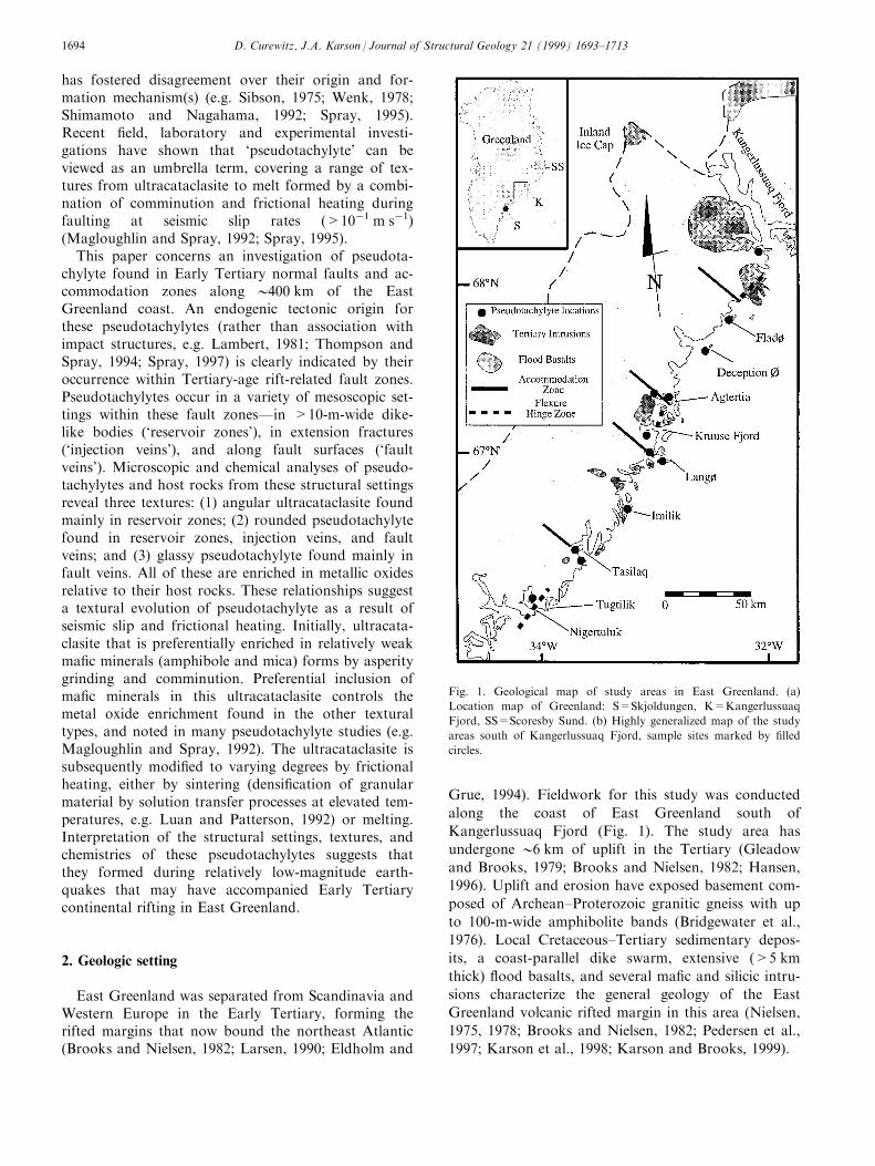
Outcrop relationships between pseudotachylyte andsurrounding rocks (Fig. 2) have been described indetail by many workers (Sibson, 1975; Grocott, 1981;Swanson, 1992). Fault veins are thin layers of pseudo-tachylyte (<2 cm wide) along faults with measurabledisplacements. Injection veins are narrow (02 cmwide), elongate (01 m long) extension fractures ®lledwith pseudotachylyte. Generation zones occur in faultzones where pseudotachylyte is thought to haveformed during seismic slip (Grocott, 1981) and arecomposed of linked faults and extension fractures withassociated arrays of fault and injection veins. Recently,generation zones have been recognized as overlappingtips of faults in en e chelon arrays (Swanson, 1992).Reservoir zones (Sibson, 1975) are large, dike-likepseudotachylyte bodies that are commonly >10 mwide and occupy extensional voids in fault zones. Thefollowing sections describe the macro- and microscopiccharacteristics of the Tertiary East Greenland pseudo-tachylytes in these structural settings.
3.1. Characteristics of pseudotachylyte-bearing faults
The Tertiary pseudotachylyte in East Greenland isdark gray to brown or black and consists of massive,aphanitic material that exhibits conchoidal to roughlyplanar fractures. Fresh pseudotachylyte surfaces com-monly exhibit vitreous to waxy luster. In thin sectionthe pseudotachylyte matrix ranges from isotropic in afew cases, to `blotchy' or variolitic in many instances.Rounded to angular clasts of host rock that vary from>1.0 m to <0.001 m in diameter are visible in thepseudotachylyte matrix, and mineral fragments assmall as 10 mm across are visible in scanning electronmicroscope (SEM) images. Mineral veins consisting ofepidote, calcite, quartz, muscovite and, in rare instances,prehnite, hematite, or limonite are visible both in handsample and in thin section. These cross-cut the pseudo-tachylyte, showing that hydrothermal activity andveining post-dated pseudotachylyte generation.
Fig. 2. Schematic diagram showing the geometry of pseudotachylyte-
bearing faults. (a) Fault veins and injection veins. (b) Generation
zones. (c) Pseudotachylyte breccia bodies. See text for descriptions.
D. Curewitz, J.A. Karson / Journal of Structural Geology 21 (1999) 1693±1713 1695
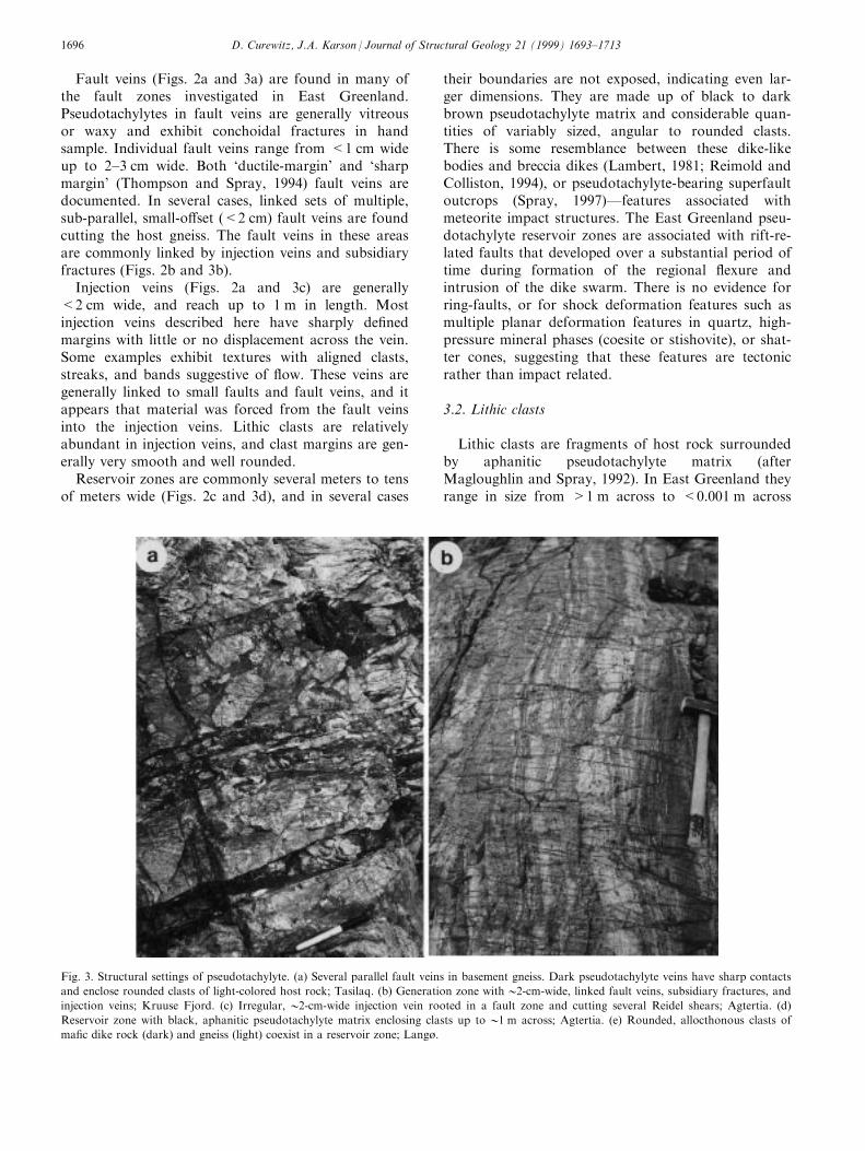
Fault veins (Figs. 2a and 3a) are found in many ofthe fault zones investigated in East Greenland.Pseudotachylytes in fault veins are generally vitreousor waxy and exhibit conchoidal fractures in handsample. Individual fault veins range from <1 cm wideup to 2±3 cm wide. Both `ductile-margin' and `sharpmargin' (Thompson and Spray, 1994) fault veins aredocumented. In several cases, linked sets of multiple,sub-parallel, small-o�set (<2 cm) fault veins are foundcutting the host gneiss. The fault veins in these areasare commonly linked by injection veins and subsidiaryfractures (Figs. 2b and 3b).
Injection veins (Figs. 2a and 3c) are generally<2 cm wide, and reach up to 1 m in length. Mostinjection veins described here have sharply de®nedmargins with little or no displacement across the vein.Some examples exhibit textures with aligned clasts,streaks, and bands suggestive of ¯ow. These veins aregenerally linked to small faults and fault veins, and itappears that material was forced from the fault veinsinto the injection veins. Lithic clasts are relativelyabundant in injection veins, and clast margins are gen-erally very smooth and well rounded.
Reservoir zones are commonly several meters to tensof meters wide (Figs. 2c and 3d), and in several cases
their boundaries are not exposed, indicating even lar-ger dimensions. They are made up of black to darkbrown pseudotachylyte matrix and considerable quan-tities of variably sized, angular to rounded clasts.There is some resemblance between these dike-likebodies and breccia dikes (Lambert, 1981; Reimold andColliston, 1994), or pseudotachylyte-bearing superfaultoutcrops (Spray, 1997)Ðfeatures associated withmeteorite impact structures. The East Greenland pseu-dotachylyte reservoir zones are associated with rift-re-lated faults that developed over a substantial period oftime during formation of the regional ¯exure andintrusion of the dike swarm. There is no evidence forring-faults, or for shock deformation features such asmultiple planar deformation features in quartz, high-pressure mineral phases (coesite or stishovite), or shat-ter cones, suggesting that these features are tectonicrather than impact related.
3.2. Lithic clasts
Lithic clasts are fragments of host rock surroundedby aphanitic pseudotachylyte matrix (afterMagloughlin and Spray, 1992). In East Greenland theyrange in size from >1 m across to <0.001 m across
Fig. 3. Structural settings of pseudotachylyte. (a) Several parallel fault veins in basement gneiss. Dark pseudotachylyte veins have sharp contacts
and enclose rounded clasts of light-colored host rock; Tasilaq. (b) Generation zone with02-cm-wide, linked fault veins, subsidiary fractures, and
injection veins; Kruuse Fjord. (c) Irregular, 02-cm-wide injection vein rooted in a fault zone and cutting several Reidel shears; Agtertia. (d)
Reservoir zone with black, aphanitic pseudotachylyte matrix enclosing clasts up to 01 m across; Agtertia. (e) Rounded, allocthonous clasts of
ma®c dike rock (dark) and gneiss (light) coexist in a reservoir zone; Langù.
D. Curewitz, J.A. Karson / Journal of Structural Geology 21 (1999) 1693±17131696

Fig. 3. (continued).
D. Curewitz, J.A. Karson / Journal of Structural Geology 21 (1999) 1693±1713 1697
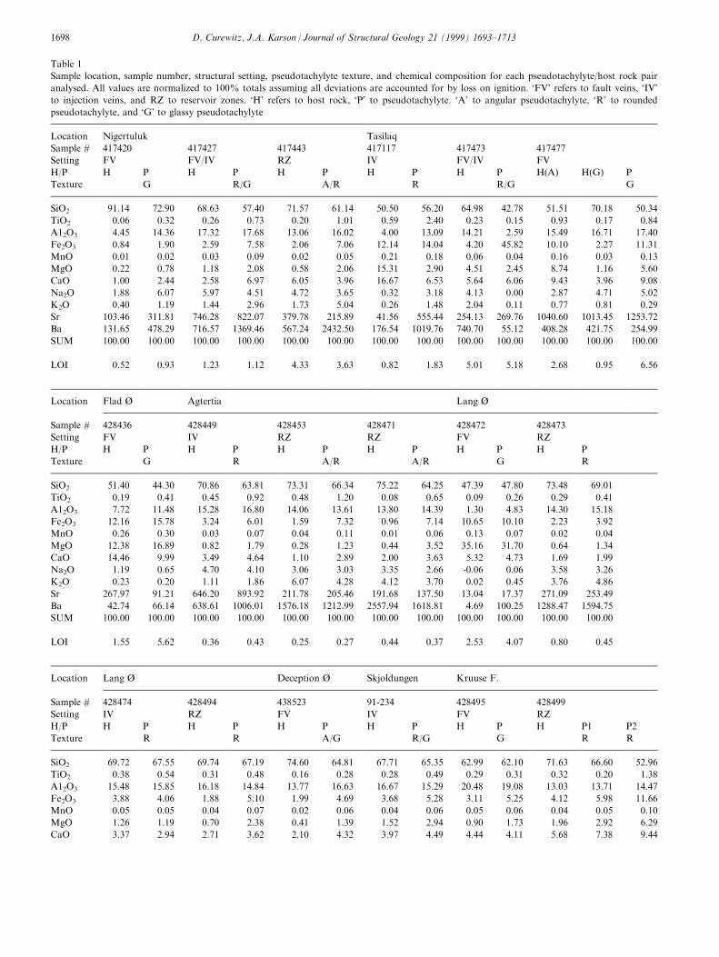
Table 1
Sample location, sample number, structural setting, pseudotachylyte texture, and chemical composition for each pseudotachylyte/host rock pair
analysed. All values are normalized to 100% totals assuming all deviations are accounted for by loss on ignition. `FV' refers to fault veins, `IV'
to injection veins, and RZ to reservoir zones. `H' refers to host rock, `P' to pseudotachylyte. `A' to angular pseudotachylyte, `R' to rounded
pseudotachylyte, and `G' to glassy pseudotachylyte
Location Nigertuluk Tasilaq
Sample # 417420 417427 417443 417117 417473 417477
Setting FV FV/IV RZ IV FV/IV FV
H/P H P H P H P H P H P H(A) H(G) P
Texture G R/G A/R R R/G G
SiO2 91.14 72.90 68.63 57.40 71.57 61.14 50.50 56.20 64.98 42.78 51.51 70.18 50.34
TiO2 0.06 0.32 0.26 0.73 0.20 1.01 0.59 2.40 0.23 0.15 0.93 0.17 0.84
A12O3 4.45 14.36 17.32 17.68 13.06 16.02 4.00 13.09 14.21 2.59 15.49 16.71 17.40
Fe2O3 0.84 1.90 2.59 7.58 2.06 7.06 12.14 14.04 4.20 45.82 10.10 2.27 11.31
MnO 0.01 0.02 0.03 0.09 0.02 0.05 0.21 0.18 0.06 0.04 0.16 0.03 0.13
MgO 0.22 0.78 1.18 2.08 0.58 2.06 15.31 2.90 4.51 2.45 8.74 1.16 5.60
CaO 1.00 2.44 2.58 6.97 6.05 3.96 16.67 6.53 5.64 6.06 9.43 3.96 9.08
Na2O 1.88 6.07 5.97 4.51 4.72 3.65 0.32 3.18 4.13 0.00 2.87 4.71 5.02
K2O 0.40 1.19 1.44 2.96 1.73 5.04 0.26 1.48 2.04 0.11 0.77 0.81 0.29
Sr 103.46 311.81 746.28 822.07 379.78 215.89 41.56 555.44 254.13 269.76 1040.60 1013.45 1253.72
Ba 131.65 478.29 716.57 1369.46 567.24 2432.50 176.54 1019.76 740.70 55.12 408.28 421.75 254.99
SUM 100.00 100.00 100.00 100.00 100.00 100.00 100.00 100.00 100.00 100.00 100.00 100.00 100.00
LOI 0.52 0.93 1.23 1.12 4.33 3.63 0.82 1.83 5.01 5.18 2.68 0.95 6.56
Location Flad é Agtertia Lang é
Sample # 428436 428449 428453 428471 428472 428473
Setting FV IV RZ RZ FV RZ
H/P H P H P H P H P H P H P
Texture G R A/R A/R G R
SiO2 51.40 44.30 70.86 63.81 73.31 66.34 75.22 64.25 47.39 47.80 73.48 69.01
TiO2 0.19 0.41 0.45 0.92 0.48 1.20 0.08 0.65 0.09 0.26 0.29 0.41
A12O3 7.72 11.48 15.28 16.80 14.06 13.61 13.80 14.39 1.30 4.83 14.30 15.18
Fe2O3 12.16 15.78 3.24 6.01 1.59 7.32 0.96 7.14 10.65 10.10 2.23 3.92
MnO 0.26 0.30 0.03 0.07 0.04 0.11 0.01 0.06 0.13 0.07 0.02 0.04
MgO 12.38 16.89 0.82 1.79 0.28 1.23 0.44 3.52 35.16 31.70 0.64 1.34
CaO 14.46 9.99 3.49 4.64 1.10 2.89 2.00 3.63 5.32 4.73 1.69 1.99
Na2O 1.19 0.65 4.70 4.10 3.06 3.03 3.35 2.66 -0.06 0.06 3.58 3.26
K2O 0.23 0.20 1.11 1.86 6.07 4.28 4.12 3.70 0.02 0.45 3.76 4.86
Sr 267.97 91.21 646.20 893.92 211.78 205.46 191.68 137.50 13.04 17.37 271.09 253.49
Ba 42.74 66.14 638.61 1006.01 1576.18 1212.99 2557.94 1618.81 4.69 100.25 1288.47 1594.75
SUM 100.00 100.00 100.00 100.00 100.00 100.00 100.00 100.00 100.00 100.00 100.00 100.00
LOI 1.55 5.62 0.36 0.43 0.25 0.27 0.44 0.37 2.53 4.07 0.80 0.45
Location Lang é Deception é Skjoldungen Kruuse F.
Sample # 428474 428494 438523 91-234 428495 428499
Setting IV RZ FV IV FV RZ
H/P H P H P H P H P H P H P1 P2
Texture R R A/G R/G G R R
SiO2 69.72 67.55 69.74 67.19 74.60 64.81 67.71 65.35 62.99 62.10 71.63 66.60 52.96
TiO2 0.38 0.54 0.31 0.48 0.16 0.28 0.28 0.49 0.29 0.31 0.32 0.20 1.38
A12O3 15.48 15.85 16.18 14.84 13.77 16.63 16.67 15.29 20.48 19.08 13.03 13.71 14.47
Fe2O3 3.88 4.06 1.88 5.10 1.99 4.69 3.68 5.28 3.11 5.25 4.12 5.98 11.66
MnO 0.05 0.05 0.04 0.07 0.02 0.06 0.04 0.06 0.05 0.06 0.04 0.05 0.10
MgO 1.26 1.19 0.70 2.38 0.41 1.39 1.52 2.94 0.90 1.73 1.96 2.92 6.29
CaO 3.37 2.94 2.71 3.62 2.10 4.32 3.97 4.49 4.44 4.11 5.68 7.38 9.44
D. Curewitz, J.A. Karson / Journal of Structural Geology 21 (1999) 1693±17131698
(Fig. 3d and e), and are angular to rounded in pro®le.The gneissic foliation in the clasts is commonly foundat varying angles to the surrounding foliation, indicat-ing signi®cant rotation. Polymict pseudotachylytescontain both local and allocthonous clasts (Fig. 3e), in-dicating signi®cant amounts of transport (at least sev-eral meters) along the fault zones. The clasts arehighly fractured and invaded by pseudotachylyte veins.Cross-cutting relationships show that many intra-clastfractures and veins are truncated by texturally distinctpseudotachylyte at the clast edges. These cross-cuttingrelationships could be interpreted as evidence for mul-tiple pseudotachylyte generations, or as evidence forrapid formation of large reservoir zones from gener-ation zones (e.g. Sibson, 1975).
Where lithic clasts are well rounded, they commonlyindent one another in a manner similar to that foundin meta-conglomerates a�ected by pressure solution(Mosher, 1976). Rounded clasts in thin section com-monly exhibit haloes of progressively smaller quartzand feldspar neoblasts toward their margins. Thesetextures suggest that rounding occurred by chemicalreaction and di�usion along clast margins, or anneal-ing by contact with the hot pseudotachylyte matrix(Magloughlin and Spray, 1992; Magloughlin, 1998).These interpretations will be addressed in more detailin the following sections.
4. Analytical methods
Eighteen samples were selected from nine locationsalong the East Greenland margin, representing the fullrange of structural settings and vein geometries in thisregion (Table 1). Textural, chemical, and mineralogicalanalyses were conducted on each sample using a var-iety of analytical techniques. Comparison of these dataamong pseudotachylytes found in fault veins, injectionveins, and reservoir zones sheds light on pseudotachy-
lyte generation and preservation in these di�erentareas.
Polished thin sections from the selected sampleswere described, photographed, and then carbon-coatedto 0250 AÊ thickness in a Denton Vacuum DV-502Avacuum evaporator in preparation for microprobeanalysis. Microprobe analyses were made using aCameca Camebax microprobe set to 15 keV, 20 nA.All analyses were made using the quantitative energydispersive spectrometer via the FLAME1 operatingsystem with natural mineral standards. Point, wide-beam (20±50 mm), and raster analyses were made atvarious scales and in di�erent domains of each thinsection in order to determine the composition of pseu-dotachylyte matrices, clasts, and other features, suchas haloes around grains, opaque mineral compositions,and hydrothermal vein compositions.
Chips of pseudotachylyte and host rocks were takenfrom the hand samples, cleaned, and crushed in a ringmill. Loss on ignition was measured by heating thepowdered samples for 1 h at 9008C. The samples werethen weighed, mixed with lithium metaborate ¯ux,melted, and dissolved in nitric acid solution. Themajor element chemistry of the pseudotachylyte andhost rock samples was then determined using aDirectly Coupled Plasma (DCP) spectrometer.
Samples were imaged using a Phillips 501 scanningelectron microscope (SEM). Representative pieces ofveins, clasts, and host rock were mounted on SEMstubs; the stub and sample base were coated with elec-tro-conductive carbon paint, and the entire samplegold coated in an ISI sputter coater. Coated sampleswere then imaged at a variety of magni®cations inorder to highlight textural characteristics. Additionalimages were taken using the microprobe, and theseimages include semi-quantitative element maps ofselected areas of the thin sections.
The comparative mineralogy of pseudotachylyteveins and host rocks was determined semi-quantitat-
Table 1 (continued)
Location Lang é Deception é Skjoldungen Kruuse F.
Sample # 428474 428494 438523 91-234 428495 428499
Setting IV RZ FV IV FV RZ
H/P H P H P H P H P H P H P1 P2
Texture R R A/G R/G G R R
Na2O 4.65 3.61 3.78 3.74 3.70 7.71 4.66 4.17 6.36 5.40 2.21 1.59 0.94
K2O 1.21 4.22 4.66 2.58 3.25 0.12 1.47 1.91 1.38 1.95 1.02 1.57 2.75
Sr 317.27 270.63 411.52 329.28 165.55 228.31 500.22 615.46 411.25 543.43 100.06 117.48 84.43
Ba 200.11 1422.12 1457.96 1364.91 1028.70 27.91 623.17 836.19 687.63 911.35 247.11 205.49 315.37
SUM 100.00 100.00 100.00 100.00 100.00 100.00 100.00 100.00 100.00 100.00 100.00 100.00 100.00
LOI 0.82 0.53 0.52 0.66 0.36 0.36 1.45 1.65 0.96 0.89 1.02 0.86 0.91
D. Curewitz, J.A. Karson / Journal of Structural Geology 21 (1999) 1693±1713 1699
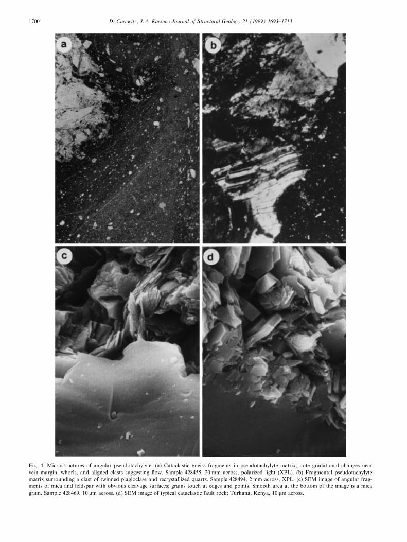
Fig. 4. Microstructures of angular pseudotachylyte. (a) Cataclastic gneiss fragments in pseudotachylyte matrix; note gradational changes near
vein margin, whorls, and aligned clasts suggesting ¯ow. Sample 428455, 20 mm across, polarized light (XPL). (b) Fragmental pseudotachylyte
matrix surrounding a clast of twinned plagioclase and recrystallized quartz. Sample 428494, 2 mm across, XPL. (c) SEM image of angular frag-
ments of mica and feldspar with obvious cleavage surfaces; grains touch at edges and points. Smooth area at the bottom of the image is a mica
grain. Sample 428469, 10 mm across. (d) SEM image of typical cataclastic fault rock; Turkana, Kenya, 10 mm across.
D. Curewitz, J.A. Karson / Journal of Structural Geology 21 (1999) 1693±17131700
ively using a Phillips XRG-3000 X-Ray Di�ractometer(XRD) set to 35 keV at 20 nA using a Cu-Ka1 source.Samples were ground and sieved to ensure uniform100 mm grain size. Weathered materials and vein ma-terials were picked out by hand, the powder wasmixed with alcohol, and this slurry was mounted onstandard petrographic slides. The slides were run from58 to 908 2y in steps of 0.058 2y, and analysed for 1.0 sper step. The resulting spectrum was analysed for peakheight and position for qualitative mineralogical infor-mation, and compared to a glass standard to check forthe presence of amorphous phases.
5. Results and interpretation
Three textural types of pseudotachylyte are recog-nized in the East Greenland sample suite: angularpseudotachylyte is essentially ultracataclasite withangular clasts and fragments on all scales; roundedpseudotachylyte contains densely packed and inter-locking smooth, rounded, or polyhedral grains; andglassy pseudotachylyte has essentially igneous textures.These designations refer to the textural characteristicsof the aphanitic matrix of the pseudotachylytesamples, visible only under high magni®cation using
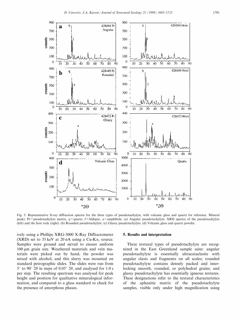
Fig. 5. Representative X-ray di�raction spectra for the three types of pseudotachylyte, with volcanic glass and quartz for reference. Mineral
peaks: Pt=pseudotachylyte matrix, q=quartz, f=feldspar, a=amphibole. (a) Angular pseudotachylyte: XRD spectra of the pseudotachylyte
(left) and the host rock (right). (b) Rounded pseudotachylyte. (c) Glassy pseudotachylyte. (d) Volcanic glass and quartz powder.
D. Curewitz, J.A. Karson / Journal of Structural Geology 21 (1999) 1693±1713 1701
optical microscope, SEM, or microprobe. The di�erenttypes occur in several associations: as discrete bands ofa single type, as adjacent bands of di�erent types withsharp contacts, or as gradational mixtures. In the lasttwo cases, the most common associations observed areangular and rounded pseudotachylyte, or rounded andglassy pseudotachylyte; only in one instance is a mix-ture of angular and glassy pseudotachylyte observed.Below, the chemical, mineralogical, and micron-scalecharacteristics of the East Greenland pseudotachylytesuite are presented within the framework of the ident-i®ed textural types.
5.1. Angular pseudotachylyte
Angular pseudotachylyte is found mainly in reser-voir zones and injection veins. In only one case isthere angular pseudotachylyte in a fault vein. Angularpseudotachylyte exhibits no evidence for any glassy orisotropic material on any scale. Locally there are ¯owtextures and bands de®ned by color changes (Fig. 4a),and by preferred orientation of elongate grains. Thematrix is granular in thin section, and clasts showtransgranular fractures and deformation twins indica-tive of cataclasis (Fig. 4b). SEM images reveal small(<10 mm) angular grains with rough surfaces, micro-
fractures, and partings along cleavage planes. Thesegrains form a highly porous framework supported bypoint contacts (Fig. 4c). SEM images of angular pseu-dotachylytes exhibit characteristics similar to catacla-sites from other fault zones (Fig. 4d). Lithic clasts arecommonly jagged, they exhibit no haloes or recrystalli-zation textures along clast margins, and they generallytouch at point contacts with little or no indentation orinterpenetration of clast margins.
X-ray di�raction (XRD) analysis of angular pseudo-tachylyte reveals that peak-to-background ratios arehigh and mineral peaks are sharp and narrow (Fig.5a), indicating that there has been little or no changein the crystallinity of the starting material, only grain-size reduction by cataclasis.
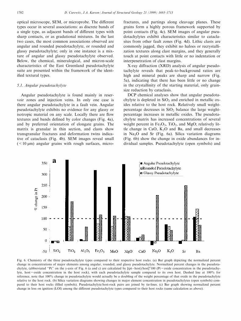
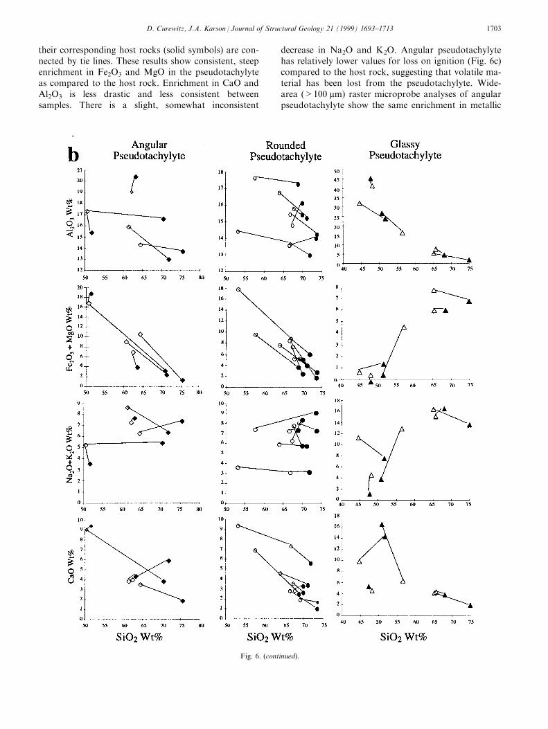
DCP chemical analyses show that angular pseudota-chylyte is depleted in SiO2 and enriched in metallic ox-ides relative to the host rock. Relatively small weight-percentage decreases in SiO2 balance the large weight-percentage increases in metallic oxides. The pseudota-chylyte matrix has increased concentrations of severalweight percent in Fe2O3, TiO2, and MgO; relatively lit-tle change in CaO, K2O and Ba, and small decreasesin Na2O and Sr (Fig. 6a). Silica variation diagrams(Fig. 6b) show the change in oxide abundances for in-dividual samples. Pseudotachylyte (open symbols) and
Fig. 6. Chemistry of the three pseudotachylyte types compared to their respective host rocks. (a) Bar graph depicting the normalized percent
change in concentrations of major elements among angular, rounded, and glassy pseudotachylyte. Normalized percent changes in the pseudota-
chylyte, (abbreviated ``Pt'' on the y-axis of Fig. 6 (a and c) are calculated by [(ptÿhost)/host]�100 (Pt=oxide concentration in the pseudotachy-
lyte, host=oxide concentration in the host rock), with each pseudotachylyte sample compared to its own host. Dashed line at 100% for
reference, note that 100% change in pseudotachylyte would actually be a doubling of the weight percentage of that oxide in the pseudotachylyte
relative to the host rock. (b) Silica variation diagrams showing changes in major element concentration in pseudotachylytes (open symbols) com-
pared to their host rocks (®lled symbols). Pseudotachylyte/host-rock pairs are joined by tie-lines. (c) Bar graph showing normalized percent
change in loss on ignition (LOI) among the di�erent pseudotachylyte types compared to their host rocks (same calculation as above).
D. Curewitz, J.A. Karson / Journal of Structural Geology 21 (1999) 1693±17131702
their corresponding host rocks (solid symbols) are con-nected by tie lines. These results show consistent, steepenrichment in Fe2O3 and MgO in the pseudotachylyteas compared to the host rock. Enrichment in CaO andAl2O3 is less drastic and less consistent betweensamples. There is a slight, somewhat inconsistent
decrease in Na2O and K2O. Angular pseudotachylytehas relatively lower values for loss on ignition (Fig. 6c)compared to the host rock, suggesting that volatile ma-terial has been lost from the pseudotachylyte. Wide-area (>100 mm) raster microprobe analyses of angularpseudotachylyte show the same enrichment in metallic
Fig. 6. (continued).
D. Curewitz, J.A. Karson / Journal of Structural Geology 21 (1999) 1693±1713 1703
oxides seen in the DCP analysis. Point analyses madeusing the microprobe reveal a highly variable chem-istry corresponding to individual quartz, feldspar,mica, and amphibole mineral compositions.
The textures, mineralogy, and chemistry of angularpseudotachylyte suggest that it formed by cataclasis,friction wear, and/or collapse of extensional micro-crack walls during faulting. During this process thehost rocks are ground to a ®ne powder, but individualmineral grains persist. Photomicrographs, SEMimages, and microprobe analyses show that amphiboleor mica grains are common in the ®ne-grained pseudo-tachylyte matrix, while most of the lithic clasts are richin feldspar or quartz. Individual grains are distinct,surfaces are rough, and extinction patterns commonlyshow deformation twins and transgranular fractures,suggestive of cataclastic deformation. There is no tex-tural evidence for solution transfer along grain bound-aries, nor is there evidence for melting. Theseobservations suggest that preferential crushing ofhydrated ma®c minerals (weaker phases) and exclusionof quartz and feldspar (stronger phases) account forthe chemical changes (enrichment in metallic oxides,depletion in SiO2 and Sr, and unchanging concen-tration of CaO and A12O3) documented in angularpseudotachylyte.
5.2. Rounded pseudotachylyte
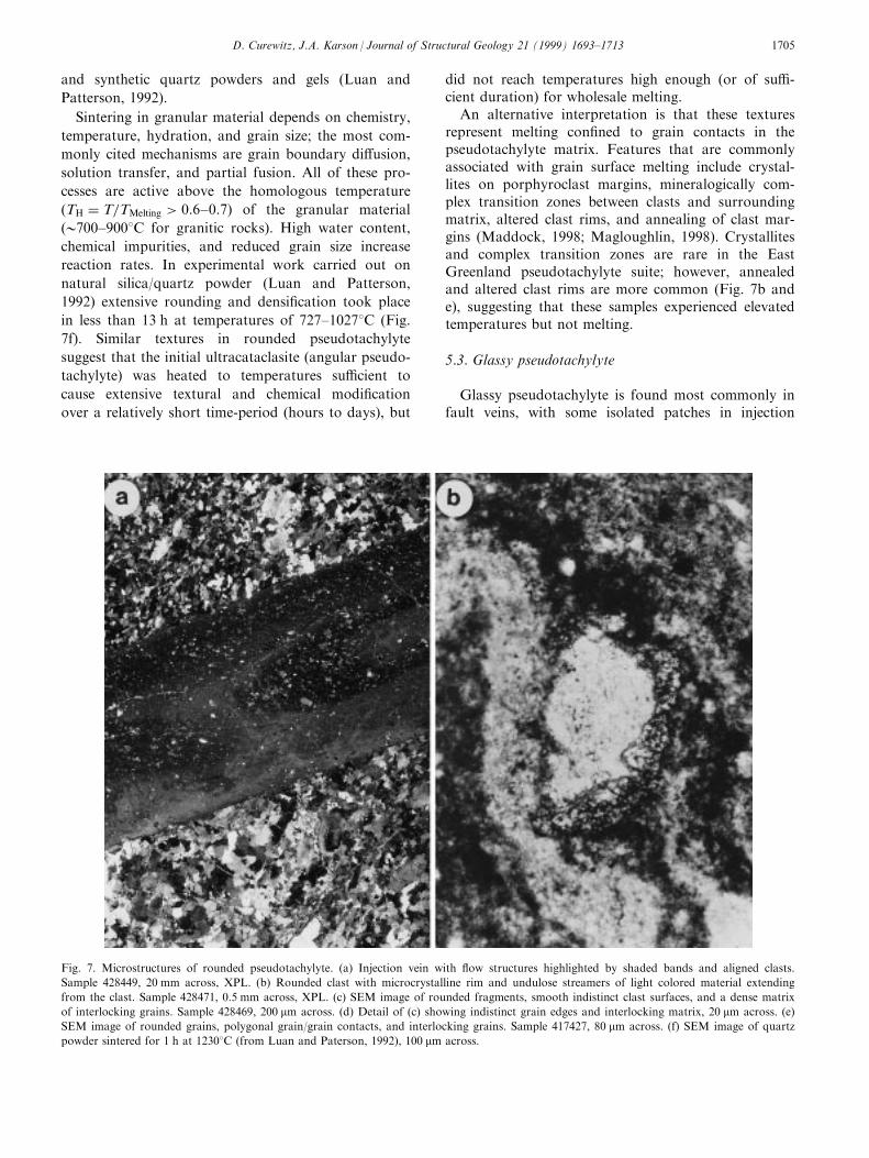
Rounded pseudotachylyte is found in reservoirzones, injection veins, and fault veins, and commonlyexhibits ¯ow textures (Fig. 7a). The pseudotachylyteconsists of millimeter-scale lithic clasts in a microgra-
nular matrix with sparse patches of isotropic material.
Lithic clasts visible under optical microscope are com-monly rounded, their centers have identi®able mineral
grains, and their margins are commonly much ®nergrained and exhibit 1208 triple junctions along neo-
blast boundaries. Clasts on all scales are rounded and
interpenetrative forming a closely packed mass. Manyclasts and grains exhibit well-developed haloes and
recrystallized clast margins (Fig. 7b). SEM images
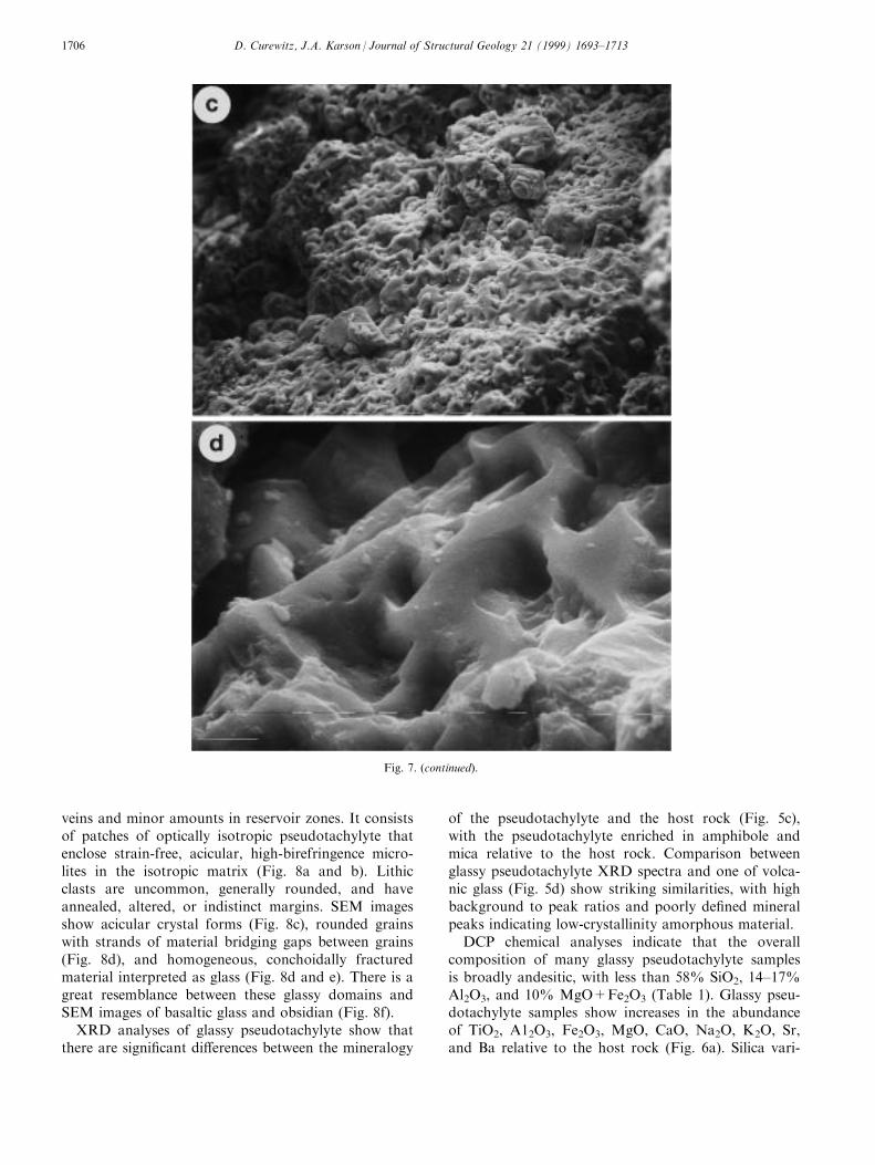
show that the matrix is made up of interlocking grainsthat are either rounded or have polyhedral shapes
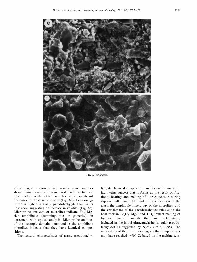
(Fig. 7c and d). The same SEM images show large
domains with conchoidal fracture and no visible crys-tal faces (Fig. 7e). These are interpreted as glassy
domains within the mainly granular matrix.
XRD analyses of rounded pseudotachylyte show
somewhat broad, depressed mineral peaks and higher
levels of background noise than angular pseudotachy-lyte (Fig. 5b). This suggests that the pseudotachylyte
matrix has a slightly lower degree of crystallinity than
the host rock.
DCP chemical analyses of rounded pseudotachylyte
show minor increases in the relative abundance ofTiO2, Fe2O3, and MgO relative to the host rock (Fig.
6a). Silica variation diagrams for rounded pseudota-
chylytes show signi®cant increases in Fe2O3 and MgOcompared to the host rocks; however, these increases
are less steep than those observed in angular pseudota-
chylytes (Fig. 6b). Slight increases also occur in Al2O3,Sr and CaO. Minor decreases occur in the abundance
of Na2O and K2O. Rounded pseudotachylytes show a
minor decrease in loss on ignition relative to the hostmaterial (Fig. 6c). Microprobe analyses of rounded
pseudotachylyte reveal a similar enrichment in metallic
oxides, and show heterogeneous distribution of Al2O3,Na2O, K2O, and CaO. Haloes around the quartz- and
feldspar-rich grains are particularly enriched in theseelements in concert with the mineralogy of the sur-
rounded clasts.
Rounded pseudotachylyte is interpreted as a sinteredultracataclasite, where sintering is de®ned as densi®ca-
tion of a porous granular matrix by solution transfer
mechanisms activated at high temperature (Luan andPatterson, 1992). Textures commonly include rounded
to polyhedral, interlocking grains on microscopicscales. There are also rare patches of glassy material
found in the rounded matrix. The compositional simi-
larity between clasts and surrounding haloes suggeststhe operation of some form of solution-transfer, di�u-
sion, or partial melting along grain boundaries
(Magloughlin, 1992, 1998; Maddock, 1998). Similartextures and chemical relationships have been docu-
mented during experimental sintering or hot pressing
of olivine (Schwenn and Goetze, 1978), calcite andquartz aggregates (Caristan et al., 1981), and natural
Fig. 6. (continued).
D. Curewitz, J.A. Karson / Journal of Structural Geology 21 (1999) 1693±17131704
and synthetic quartz powders and gels (Luan and
Patterson, 1992).
Sintering in granular material depends on chemistry,
temperature, hydration, and grain size; the most com-
monly cited mechanisms are grain boundary di�usion,
solution transfer, and partial fusion. All of these pro-
cesses are active above the homologous temperature
(TH � T=TMelting > 0:6±0:7) of the granular material
(0700±9008C for granitic rocks). High water content,
chemical impurities, and reduced grain size increase
reaction rates. In experimental work carried out on
natural silica/quartz powder (Luan and Patterson,
1992) extensive rounding and densi®cation took place
in less than 13 h at temperatures of 727±10278C (Fig.
7f). Similar textures in rounded pseudotachylyte
suggest that the initial ultracataclasite (angular pseudo-
tachylyte) was heated to temperatures su�cient to
cause extensive textural and chemical modi®cation
over a relatively short time-period (hours to days), but
did not reach temperatures high enough (or of su�-cient duration) for wholesale melting.
An alternative interpretation is that these texturesrepresent melting con®ned to grain contacts in thepseudotachylyte matrix. Features that are commonlyassociated with grain surface melting include crystal-lites on porphyroclast margins, mineralogically com-plex transition zones between clasts and surroundingmatrix, altered clast rims, and annealing of clast mar-gins (Maddock, 1998; Magloughlin, 1998). Crystallitesand complex transition zones are rare in the EastGreenland pseudotachylyte suite; however, annealedand altered clast rims are more common (Fig. 7b ande), suggesting that these samples experienced elevatedtemperatures but not melting.
5.3. Glassy pseudotachylyte
Glassy pseudotachylyte is found most commonly infault veins, with some isolated patches in injection
Fig. 7. Microstructures of rounded pseudotachylyte. (a) Injection vein with ¯ow structures highlighted by shaded bands and aligned clasts.
Sample 428449, 20 mm across, XPL. (b) Rounded clast with microcrystalline rim and undulose streamers of light colored material extending
from the clast. Sample 428471, 0.5 mm across, XPL. (c) SEM image of rounded fragments, smooth indistinct clast surfaces, and a dense matrix
of interlocking grains. Sample 428469, 200 mm across. (d) Detail of (c) showing indistinct grain edges and interlocking matrix, 20 mm across. (e)
SEM image of rounded grains, polygonal grain/grain contacts, and interlocking grains. Sample 417427, 80 mm across. (f) SEM image of quartz
powder sintered for 1 h at 12308C (from Luan and Paterson, 1992), 100 mm across.
D. Curewitz, J.A. Karson / Journal of Structural Geology 21 (1999) 1693±1713 1705
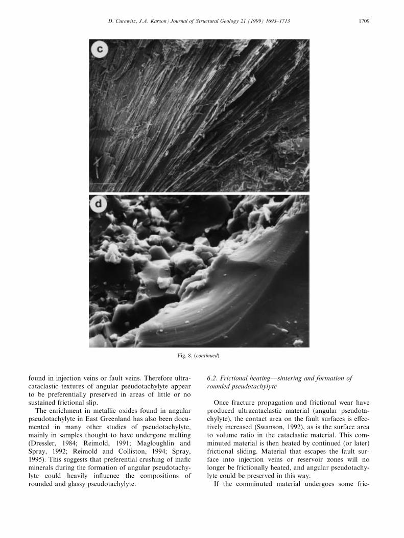
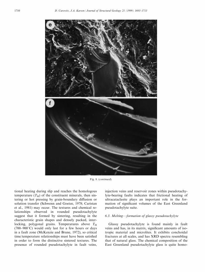
veins and minor amounts in reservoir zones. It consistsof patches of optically isotropic pseudotachylyte thatenclose strain-free, acicular, high-birefringence micro-lites in the isotropic matrix (Fig. 8a and b). Lithicclasts are uncommon, generally rounded, and haveannealed, altered, or indistinct margins. SEM imagesshow acicular crystal forms (Fig. 8c), rounded grainswith strands of material bridging gaps between grains(Fig. 8d), and homogeneous, conchoidally fracturedmaterial interpreted as glass (Fig. 8d and e). There is agreat resemblance between these glassy domains andSEM images of basaltic glass and obsidian (Fig. 8f).
XRD analyses of glassy pseudotachylyte show thatthere are signi®cant di�erences between the mineralogy
of the pseudotachylyte and the host rock (Fig. 5c),with the pseudotachylyte enriched in amphibole andmica relative to the host rock. Comparison betweenglassy pseudotachylyte XRD spectra and one of volca-nic glass (Fig. 5d) show striking similarities, with highbackground to peak ratios and poorly de®ned mineralpeaks indicating low-crystallinity amorphous material.
DCP chemical analyses indicate that the overallcomposition of many glassy pseudotachylyte samplesis broadly andesitic, with less than 58% SiO2, 14±17%Al2O3, and 10% MgO+Fe2O3 (Table 1). Glassy pseu-dotachylyte samples show increases in the abundanceof TiO2, A12O3, Fe2O3, MgO, CaO, Na2O, K2O, Sr,and Ba relative to the host rock (Fig. 6a). Silica vari-
Fig. 7. (continued).
D. Curewitz, J.A. Karson / Journal of Structural Geology 21 (1999) 1693±17131706
ation diagrams show mixed results: some samplesshow minor increases in some oxides relative to theirhost rocks, while other samples show signi®cantdecreases in those same oxides (Fig. 6b). Loss on ig-nition is higher in glassy pseudotachylyte than in itshost rock, suggesting an increase in volatiles (Fig. 6c).Microprobe analyses of microlites indicate Fe-, Mg-rich amphiboles (cummingtonite or grunerite), inagreement with optical analysis. Microprobe analysesof the isotropic domains surrounding the amphibolemicrolites indicate that they have identical compo-sitions.
The textural characteristics of glassy pseudotachy-
lyte, its chemical composition, and its predominance in
fault veins suggest that it forms as the result of fric-
tional heating and melting of ultracataclasite during
slip on fault planes. The andesitic composition of the
glass, the amphibole mineralogy of the microlites, and
the enrichment of the pseudotachylyte relative to the
host rock in Fe2O3, MgO and TiO2, re¯ect melting of
hydrated ma®c minerals that are preferentially
included in the initial ultracataclasite (angular pseudo-
tachylyte) as suggested by Spray (1992, 1995). The
mineralogy of the microlites suggests that temperatures
may have reached >9008C, based on the melting tem-
Fig. 7. (continued).
D. Curewitz, J.A. Karson / Journal of Structural Geology 21 (1999) 1693±1713 1707
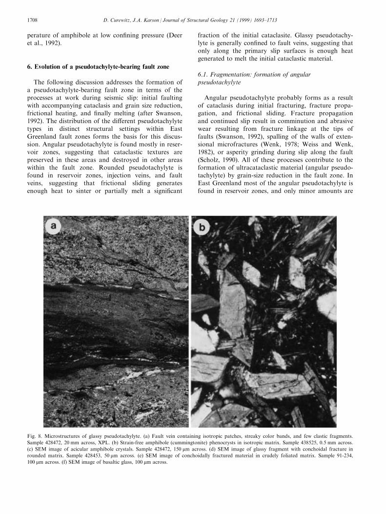
perature of amphibole at low con®ning pressure (Deeret al., 1992).
6. Evolution of a pseudotachylyte-bearing fault zone
The following discussion addresses the formation ofa pseudotachylyte-bearing fault zone in terms of theprocesses at work during seismic slip: initial faultingwith accompanying cataclasis and grain size reduction,frictional heating, and ®nally melting (after Swanson,1992). The distribution of the di�erent pseudotachylytetypes in distinct structural settings within EastGreenland fault zones forms the basis for this discus-sion. Angular pseudotachylyte is found mostly in reser-voir zones, suggesting that cataclastic textures arepreserved in these areas and destroyed in other areaswithin the fault zone. Rounded pseudotachylyte isfound in reservoir zones, injection veins, and faultveins, suggesting that frictional sliding generatesenough heat to sinter or partially melt a signi®cant
fraction of the initial cataclasite. Glassy pseudotachy-lyte is generally con®ned to fault veins, suggesting thatonly along the primary slip surfaces is enough heatgenerated to melt the initial cataclastic material.
6.1. Fragmentation: formation of angularpseudotachylyte
Angular pseudotachylyte probably forms as a resultof cataclasis during initial fracturing, fracture propa-gation, and frictional sliding. Fracture propagationand continued slip result in comminution and abrasivewear resulting from fracture linkage at the tips offaults (Swanson, 1992), spalling of the walls of exten-sional microfractures (Wenk, 1978; Weiss and Wenk,1982), or asperity grinding during slip along the fault(Scholz, 1990). All of these processes contribute to theformation of ultracataclastic material (angular pseudo-tachylyte) by grain-size reduction in the fault zone. InEast Greenland most of the angular pseudotachylyte isfound in reservoir zones, and only minor amounts are
Fig. 8. Microstructures of glassy pseudotachylyte. (a) Fault vein containing isotropic patches, streaky color bands, and few clastic fragments.
Sample 428472, 20 mm across, XPL. (b) Strain-free amphibole (cummingtonite) phenocrysts in isotropic matrix. Sample 438525, 0.5 mm across.
(c) SEM image of acicular amphibole crystals. Sample 428472, 150 mm across. (d) SEM image of glassy fragment with conchoidal fracture in
rounded matrix. Sample 428453, 50 mm across. (e) SEM image of conchoidally fractured material in crudely foliated matrix. Sample 91-234,
100 mm across. (f) SEM image of basaltic glass, 100 mm across.
D. Curewitz, J.A. Karson / Journal of Structural Geology 21 (1999) 1693±17131708
found in injection veins or fault veins. Therefore ultra-cataclastic textures of angular pseudotachylyte appearto be preferentially preserved in areas of little or nosustained frictional slip.
The enrichment in metallic oxides found in angularpseudotachylyte in East Greenland has also been docu-mented in many other studies of pseudotachylyte,mainly in samples thought to have undergone melting(Dressler, 1984; Reimold, 1991; Magloughlin andSpray, 1992; Reimold and Colliston, 1994; Spray,1995). This suggests that preferential crushing of ma®cminerals during the formation of angular pseudotachy-lyte could heavily in¯uence the compositions ofrounded and glassy pseudotachylyte.
6.2. Frictional heatingÐsintering and formation ofrounded pseudotachylyte
Once fracture propagation and frictional wear haveproduced ultracataclastic material (angular pseudota-chylyte), the contact area on the fault surfaces is e�ec-tively increased (Swanson, 1992), as is the surface areato volume ratio in the cataclastic material. This com-minuted material is then heated by continued (or later)frictional sliding. Material that escapes the fault sur-face into injection veins or reservoir zones will nolonger be frictionally heated, and angular pseudotachy-lyte could be preserved in this way.
If the comminuted material undergoes some fric-
Fig. 8. (continued).
D. Curewitz, J.A. Karson / Journal of Structural Geology 21 (1999) 1693±1713 1709
tional heating during slip and reaches the homologoustemperature (TH) of the constituent minerals, then sin-tering or hot pressing by grain-boundary di�usion orsolution transfer (Schwenn and Goetze, 1978; Caristanet al., 1981) may occur. The textures and chemical re-lationships observed in rounded pseudotachylytesuggest that it formed by sintering, resulting in thecharacteristic grain shapes and densely packed, inter-locking, polygonal grains. Temperatures above TH
(700±9008C) would only last for a few hours or daysin a fault zone (McKenzie and Brune, 1972), so criticaltime/temperature relationships must have been satis®edin order to form the distinctive sintered textures. Thepresence of rounded pseudotachylyte in fault veins,
injection veins and reservoir zones within pseudotachy-lyte-bearing faults indicates that frictional heating ofultracataclasite plays an important role in the for-mation of signi®cant volumes of the East Greenlandpseudotachylyte suite.
6.3. MeltingÐformation of glassy pseudotachylyte
Glassy pseudotachylyte is found mainly in faultveins and has, in its matrix, signi®cant amounts of iso-tropic material and microlites. It exhibits conchoidalfractures at all scales, and has XRD spectra resemblingthat of natural glass. The chemical composition of theEast Greenland pseudotachylyte glass is quite homo-
Fig. 8. (continued).
D. Curewitz, J.A. Karson / Journal of Structural Geology 21 (1999) 1693±17131710
geneous, both within samples and among di�erentsamples, and is close to that of andesite. Crystalsfound in the isotropic glass are invariably Fe-, Mg-richamphiboles (cummingtonite or grunerite) with crystalli-zation temperatures around 9008C. The glass and thecrystals have identical chemical compositions. Theserelationships suggest that glassy pseudotachylyteformed by melting of ultracataclasite during seismicslip.
6.4. Implications for tectonic environment
The large volumes of pseudotachylyte and the out-crop characteristics of many exposures found alongfault zones in East Greenland are similar to pseudota-chylyte outcrops found in meteorite impact structures.However, the East Greenland pseudotachylytes havean endogenic, tectonic origin related to continentalrifting, and lack any of the distinctive features charac-teristic of hypervelocity impact sites (including shattercones, ring structures, shocked mineral grains, pre-served layers of ejecta).
Textural relationships, estimates of the temperaturesreached during faulting (0700±9008C), and estimatesof pseudotachylyte volume in individual outcropsbroadly constrain the thermal energy imparted to theinitial ultracataclasite. These estimates are used to de-rive rough values of seismic work and earthquakemagnitude. Such estimates are fraught with assump-tions about the actual volume of pseudotachylyte pro-duced, the size and shape of the earthquake slip-patch,and the amount of pseudotachylyte produced during asingle seismic event. Given the temperature constraintsand the excellent exposure in East Greenland, how-ever, these estimates provide rough maximum valuesof earthquake magnitude. The large volumes of pseu-dotachylyte in individual fault zones (some outcropsare >20 m on a side, i.e. Fig. 3d) and the relativelylow temperatures (<7008C) indicated by preserved cat-aclastic textures in many samples suggest that thepseudotachylytes formed during relatively small earth-quakes (moment magnitude (M0� < 4). These estimatesare in agreement with data from the Basin and Range(Sibson, 1982, 1983), indicating widespread, shallowmicroseismicity in a tectonic environment similar tothe continental rift setting envisioned for the Tertiaryin East Greenland. The widespread occurrence of pseu-dotachylyte in association with rift-related faults alongnearly 400 km of the East Greenland margin indicatesthat microseismicity may have played an importantrole in accommodating deformation of the TertiaryEast Greenland volcanic rifted margin.
7. Conclusions
Pseudotachylytes in fault veins, injection veins, andreservoir zones have been sampled from Early Tertiarynormal faults and accommodation zones along nearly400 km of the East Greenland volcanic rifted margin.Three textural types of pseudotachylyte have beenidenti®ed: angular, rounded, and glassy. These texturesvary between di�erent structural settings, with angularpseudotachylyte found mainly in reservoir zones,rounded pseudotachylyte found in reservoir zones,injection veins and fault veins, and glassy pseudotachy-lyte found mainly in fault veins. Textural and chemicalrelationships in pseudotachylytes from these di�erentmesoscopic settings suggest an evolutionary sequenceof pseudotachylyte formation along fault zones. Initialfrictional sliding and comminution produced ultracata-clasite enriched in mica and amphibole fragments, withthis texture preserved in reservoir zones. Heating andsintering of ultracataclasite occurred in fault veins,injection veins, and reservoir zones. Melting was gener-ally con®ned to fault surfaces. The metal oxide enrich-ment observed in angular pseudotachylyte in¯uencesthe chemistry of rounded and glassy pseudotachylyte.These observations, combined with independent infor-mation about paleo-crustal depths, lead to the in-terpretation that shallow, relatively small (M0 < 4)earthquakes accompanied the rifting of EastGreenland from Eurasia.
Acknowledgements
Thanks to J. G. Spray, M. T. Swanson, and T.Blenkinsop for their insightful and constructivereviews. Thanks to W. M. Meurer for assistance withDCP analyses, A. E. Boudreau for assistance withmicroprobe analyses, and L. Eibest for assistance withSEM analyses. This work is part of an ongoing com-prehensive study of the Tertiary East Greenland volca-nic rifted margin conducted by the Danish LithosphereCenter (DLC), which is funded by the DanishNational Research Foundation. Structural studies weresupported by the DLC and National ScienceFoundation grant EAR-9508250 (to Karson).
References
Bridgewater, D., Keto, L., McGregor, V.R., Myers, J.S., 1976.
Archaean gneiss complex of Greenland. In: Escher, A., Watt,
W.S. (Eds.), Geology of Greenland. The Geological Survey of
Greenland, pp. 18±75.
Brooks, C.K., Nielsen, T.F.D., 1982. The Phanerozoic development
of the Kangerdlugssuaq area, East Greenland. Meddelelser ém
Grùnland Geoscience 9, 3±30.
Caristan, Y., Harpin, R.J., Evans, B., 1981. Deformation of porous
D. Curewitz, J.A. Karson / Journal of Structural Geology 21 (1999) 1693±1713 1711
aggregates of calcite and quartz using the isostatic hot-pressing
technique. Tectonophysics 78, 629±650.
Clift, P.D., Turner, J., ODP Leg 152 Scienti®c Party, 1995. Dynamic
support by the Icelandic plume and vertical tectonics of the
northeast Atlantic continental margins. Journal of Geophysical
Research 100, 24473±24486.
Deer, W.A., Howie, R.A., Zussman, J., 1992. An Introduction to the
Rock-forming Minerals. Longman Scienti®c & Technical, Essex.
Dressler, B.O., 1984. The e�ects of the Sudbury Event and the intru-
sion of the Sudbury Igneous Complex on the footwall rocks of
the Sudbury Structure. In: Pye, E.G., Naldrett, A.J., Giblin, P.E.
(Eds.), The Geology and Ore Deposits of the Sudbury Structure.
Ontario Geological Survey Special Volume 1, pp. 97±138.
Eldholm, O., Grue, K., 1994. North Atlantic volcanic margins:
dimensions and production rates. Journal of Geophysical
Research 99, 2955±2968.
Erismann, T.H., 1979. Mechanisms of large landslides. Rock
Mechanics 12, 15±46.
Gleadow, A.J.W., Brooks, C.K., 1979. Fission track dating, thermal
histories, and tectonics of igneous intrusions in East Greenland.
Contributions to Mineralogy and Petrology 71, 45±60.
Grocott, J., 1981. Fracture geometry of pseudotachylyte generation
zones: a study of shear fractures formed during seismic events.
Journal of Structural Geology 3, 169±178.
Hansen, K., 1996. Thermotectonic evidence of a rifted continental
margin: ®ssion track evidence from the Kangerlussuaq area, SE
Greenland. Terra Nova 8, 458±469.
Karson, J.A., Brooks, C.K., 1999. Structural and magmatic segmen-
tation of the Tertiary East Greenland volcanic rifted margin. In:
Ryan, P., MacNiocall, C. (Eds.), Continental Tectonics.
Geological Society, London, Special Publication, 164, 313±338.
Karson, J.A., Storey, M., Brooks, C.K., Pringle, M., 1998.
Widespread Tertiary faulting and pseudotachylytes in the East
Greenland Volcanic Rifted Margin: evidence of seismogenic fault-
ing during magmatic construction. Geology 26, 39±42.
Kennedy, L.A., Spray, J.G., 1992. Frictional melting of sedimentary
rock during high-speed diamond drilling: an analytical SEM and
TEM investigation. Tectonophysics 204, 323±337.
Lambert, P., 1981. Breccia dikes: geological constraints on the for-
mation of complex craters. In: Schultz, P.H., Merrill, R.B. (Eds.),
Multi-ring Basins. Proceedings of the Lunar and Planetary
Sciences 12A, pp. 59±78.
Larsen, H.C., Saunders, A.D., 1998. Tectonism and volcanism at the
SE Greenland rifted margin: record of plume impact and later
continental rupture. In: Saunders, A.D., Larsen, H.C., Wise, S.
(Eds.), Proceedings of the Ocean Drilling Program, Scienti®c
Results 152.
Larsen, H.C., 1990. The East Greenland Shelf. In: Grantz, A.,
Johnson, L., Sweeney, J.F. (Eds.), The Arctic Region, The
Geology of North America L. Geological Society of America, pp.
185±210.
Larsen, H.C., Saunders, A.D., Clift, P. et al., 1994. Proceedings of
the Ocean Drilling Program, Initial Reports 153. Ocean Drilling
Program, College Station, Texas.
Luan, F.C., Patterson, M.S., 1992. Preparation and deformation of
synthetic aggregates of quartz. Journal of Geophysical Research
97, 301±320.
Maddock, R.H., 1998. Pseudotachylyte formed by frictional fusion.
In: Snoke, A.W., Tullis, J., Todd, V.R. (Eds.), Fault-related
Rocks: A Photographic Atlas. Princeton University Press,
Princeton, NJ, pp. 80±87.
Magloughlin, J.F., Spray, J.G., 1992. Frictional melting processes
and products in geological materials: introduction and discussion.
Tectonophysics 204, 197±206.
Magloughlin, J.F., 1998. Melting relations within lithic clasts in
pseudotachylyte. In: Snoke, A.W., Tullis, J., Todd, V.R. (Eds.),
Fault-related Rocks: A Photographic Atlas. Princeton University
Press, Princeton, NJ, pp. 90±91.
Magloughlin, J.F., 1992. Microstructural and chemical changes as-
sociated with cataclasis and frictional melting at shallow crustal
levels: the cataclasite±pseudotachylyte connection. Tectonophysics
204, 243±260.
Masch, L., Wenk, H.R., Preuss, E., 1985. Electron microscopy study
of hyalomylonitesÐevidence for frictional melting in landslides.
Tectonophysics 115, 131±160.
McKenzie, D., Brune, J.N., 1972. Melting on fault planes during
large earthquakes. Geophysical Journal of the Royal
Astronomical Society 29, 65±78.
Mosher, S., 1976. Pressure solution as a deformation mechanism in
Pennsylvanian conglomerates from Rhode Island. Journal of
Geology 84, 355±364.
Myers, J.S., 1980. Structure of the coastal dyke swarm and associ-
ated plutonic intrusions of East Greenland. Earth and Planetary
Science Letters 46, 407±418.
Nielsen, T.F., Brooks, C.K., 1981. The East Greenland rifted conti-
nental margin: an examination of the coastal ¯exure. Journal of
the Geological Society of London 138, 559±568.
Nielsen, T.F.D., 1975. Possible mechanism of continental breakup in
the North Atlantic. Nature 253, 182±184.
Nielsen, T.F.D., 1978. The Tertiary dike swarms of the
Kangerdlugssuaq area, East Greenland: an example of magmatic
development during continental breakup. Contributions to
Mineralogy and Petrology 67, 63±78.
Pedersen, A.K., Watt, M., Watt, W.S., Larsen, L.M., 1997.
Structure and stratigraphy of the Early Tertiary basalts of the
Blosseville Kyst, East Greenland. Journal of the Geological
Society of London 154, 565±570.
Reimold, W.U., Colliston, W.P., 1994. Pseudotachylites of the
Vredefort Dome and the surrounding Witwatersrand Basin,
South Africa. In: Dressler, B.O., Grieve, R.A.F., Sharpton, V.L.
(Eds.), Large Meteorite Impacts and Planetary Evolution.
Geological Society of America Special Paper 293, pp. 177±196.
Reimold, W.U., 1991. The geochemistry of pseudotachylytes from
the Vredefort Dome, South Africa. Neues Jahrbuch
fuÈ rMineralogische Abhandlung 162, 151±184.
Scholz, C.H., 1990. The Mechanics of Earthquakes and Faulting.
Cambridge University Press, New York.
Schwenn, M.B., Goetze, C., 1978. Creep of olivine during hot-press-
ing. Tectonophysics 48, 41±60.
Scott, J.S., Drever, H.I., 1953. Frictional fusion along a Himalayan
thrust. Proceedings of the Royal Society of Edinburgh 65, 121±
142.
Shimamoto, T., Nagahama, H., 1992. An argument against the
crush origin of pseudotachylytes based on the analysis of clast-
size distribution. Journal of Structural Geology 14, 999±1006.
Sibson, R.H., 1975. Generation of pseudotachylyte by ancient seis-
mic faulting. Geophysical Journal of the Royal Astronomical
Society 43, 775±794.
Sibson, R.H., 1982. Fault zone models, heat ¯ow, and the depth dis-
tribution of earthquakes in the continental crust of the United
States. Bulletin of the Seismological Society of America 72, 151±
163.
Sibson, R.H., 1983. Continental fault structure and the shallow
earthquake source. Journal of the Geological Society of London
140, 741±767.
Spray, J.G., Thompson, L.M., 1995. Friction melt distribution in a
multi-ring impact basin. Nature 373, 130±132.
Spray, J.G., 1987. Arti®cial generation of pseudotachylyte using fric-
tion welding apparatus: simulation of melting on a fault plane.
Journal of Structural Geology 9, 49±60.
Spray, J.G., 1989. Slickenside formation by surface melting during
the mechanical excavation of rock. Journal of Structural Geology
11, 895±905.
D. Curewitz, J.A. Karson / Journal of Structural Geology 21 (1999) 1693±17131712
Spray, J.G., 1992. A physical basis for the frictional melting of some
rock forming minerals. Tectonophysics 204, 205±221.
Spray, J.G., 1995. Pseudotachylyte controversy: fact or friction?
Geology 23, 1119±1122.
Spray, J.G., 1997. Superfaults. Geology 25, 579±582.
Swanson, M.T., 1992. Fault structure, wear mechanisms and rupture
processes in pseudotachylyte generation. Tectonophysics 204,
223±242.
Tegner, C., Duncan, R.A., Bernstein, S., Brooks, C.K., Bird, D.K.,
Storey, M., 1998. 40Ar±39Ar geochronology of Tertiary ma®c
intrusions along the East Greenland rifted margin: relation to
¯ood basalts and the Iceland hotspot track. Earth and Planetary
Science Letters 156, 75±88.
Thompson, L.M., Spray, J.G., 1994. Pseudotachylytic rock distri-
bution and genesis within the Sudbury impact structure. In:
Dressler, B.O., Grieve, R.A.F., Sharpton, V.L. (Eds.), Large
Meteorite Impacts and Planetary Evolution. Geological Society
of America Special Paper 293, pp. 27±87.
Wager, L.R., Deer, W.A., 1938. A dyke swarm and crustal ¯exure in
East Greenland. Geological Magazine 75, 39±46.
Weiss, L.E., Wenk, H.R., 1982. Al-rich calcic pyroxene in pseudota-
chylyte: An indicator of high pressure and high temperature?
Tectonophysics 84, 329±341.
Wenk, H.R., 1978. Are pseudotachylyte products of fracture or
fusion? Geology 6, 507±511.
D. Curewitz, J.A. Karson / Journal of Structural Geology 21 (1999) 1693±1713 1713