Embed Size (px)
Citation preview
International Research Journal of Engineering and Technology (IRJET) e-ISSN: 2395-0056
Volume: 04 Issue: 11 | Nov -2017 www.irjet.net p-ISSN: 2395-0072
© 2017, IRJET | Impact Factor value: 6.171 | ISO 9001:2008 Certified Journal | Page 596
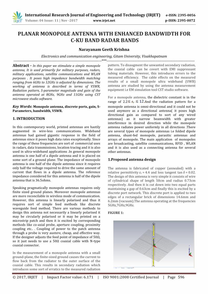
PLANAR MONOPOLE ANTENNA WITH ENHANCED BANDWIDTH FOR C-KU BAND RADAR BANDS
Narayanam Geeth Krishna
Electronics and communication engineering, Gitam University, Visakhapatnam ---------------------------------------------------------------------***---------------------------------------------------------------------Abstract - In this paper we stimulate a simple monopole antenna, It is used primarily for military purposes, radars, military applications, satellite communications and WLAN purposes . It poses high impedance bandwidth matching ranging from 6GHz to 12GHz is adjusted by dimensions. The working of antenna is described in terms of VSWR, Radiation pattern, S-parameter magnitude and gain of the antenna operated at 8GHz, 9GHz and 11GHz using CST microwave studio software.
Key Words: Monopole antenna, discrete ports, gain, S-Parameters, bandwidth, VSWR.
1. INTRODUCTION In this contemporary world, printed antennas are hastily augmented in wire-less communications. Wideband antennas had gained gigantic response in the field of antennas since it poses high data rates exceptionally. Since the range of these frequencies are sort of commercial uses in radars, data transmissions, location tracing and it is also used in ultra-wideband applications .In general monopole antenna is one half of a dipole antenna and it is placed on some sort of a ground plane. The impedance of monopole antenna is one half of the dipole antenna since it requires only half the voltage required to drive the same amount of current that flows in a dipole antenna. The reference impedance considered for this antenna is half of the dipole antenna that is 36.5ohms.
Speaking pragmatically monopole antennas requires only finite sized ground planes. Moreover monopole antennas are more reconcilable in wireless mode of communication. However, this antenna is linearly polarised and thus it requires sort of simple feed methods like discrete waveguide feed method. There are various methods to design this antenna not necessarily a linearly polarised it may be circularly polarised or it may be printed on a microstrip patch and then it is excited by corresponding methods like co-axial probe, aperture coupling, proximity coupling etc.. . Coupling of power to the patch antenna through a probe is very austere, cheap, and effective way. If the designer adjusts the feed point of impedance of 50Ω, so it just needs to use a 50Ω coaxial cable with N-type coaxial connector.
In the measurement of a monopole antenna with a small ground-plane, the finite-sized ground causes the current to flow back from the radiator to the outer surface of the coaxial cable. This results in secondary radiation which introduces some sort of erratics to the measured radiation
pattern. To disaugment the unwanted secondary radiation, the coaxial cable can be covert with EMI suppressant tubing materials. However, this introduces errors to the measured efficiency. The cable effects on the measured results of a small monopole ultra wideband (UWB) antenna are studied by using the antenna measurement equipment i.e EM simulation tool CST studio software.
For a monopole antenna, the dielectric constant is in the
range of 2.2 And the radiation pattern for a
monopole antenna is omni-directional and it could not be used anymore as a directional antenna( it poses high directional gain as compared to sort of any wired antennas) as it narrow beamwidth with greater interference in desired direction while the monopole antenna radiates power uniformly in all directions .There are several types of monopole antennas i.e folded dipole antenna, shunt-fed monopole, parasitic antennas and arrays of monopole. The main application of monopoles are broadcasting, satellite communications, RFID , WLAN and it is also used as a connecting antenna for several other antennas.
1.Proposed antenna design The antenna is fabricated of copper (annealed) with a relative permittivity εr = 4.4 and loss tangent tan δ = 0.02. The design of this antenna is very simple it consists of wire of cylindrical shape of length 50cm and radius 0.73cm respectively. And then it is cut down into two equal parts maintaining a gap of 0.63cm and finally this is excited by a discrete port network. This discrete port is applied to two edges of a rectangular brick of dimensions 14.6mm and 6.2mm (vacuum).The antenna operating at the frequencies 5GHz,7GHz,9GHz.
FIGURE 1:
International Research Journal of Engineering and Technology (IRJET) e-ISSN: 2395-0056
Volume: 04 Issue: 11 | Nov -2017 www.irjet.net p-ISSN: 2395-0072
© 2017, IRJET | Impact Factor value: 6.171 | ISO 9001:2008 Certified Journal | Page 597
The above figure 1descrige the design of an antenna in 3-D view.
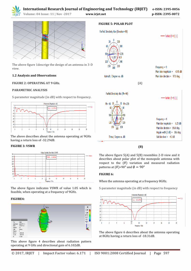
1.2 Analysis and Observations FIGURE 2: OPERATING AT 9 GHz.
PARAMETRIC ANALYSIS
S-parameter magnitude (in dB) with respect to frequency.
The above describes about the antenna operating at 9GHz having a return loss of -32.29dB.
FIGURE 3: VSWR
The above figure indicates VSWR of value 1.05 which is feasible, when operating at a frequency of 9GHz.
FIGURE4:
This above figure 4 describes about radiation pattern operating at 9 GHz and directional gain of 6.102dB.
FIGURE 5: POLAR PLOT
(A)
(B)
The above figure 5(A) and 5(B) resembles 2-D view and it describes about polar plot of the monopole antenna with
respect to the ( variation and measured radiation
patterns at ( =90 and
FIGURE 6:
When the antenna operating at a frequency 8GHz.
S-parameter magnitude (in dB) with respect to frequency
The above figure 6 describes about the antenna operating at 8GHz having a return loss of -18.31dB.
International Research Journal of Engineering and Technology (IRJET) e-ISSN: 2395-0056
Volume: 04 Issue: 11 | Nov -2017 www.irjet.net p-ISSN: 2395-0072
© 2017, IRJET | Impact Factor value: 6.171 | ISO 9001:2008 Certified Journal | Page 598
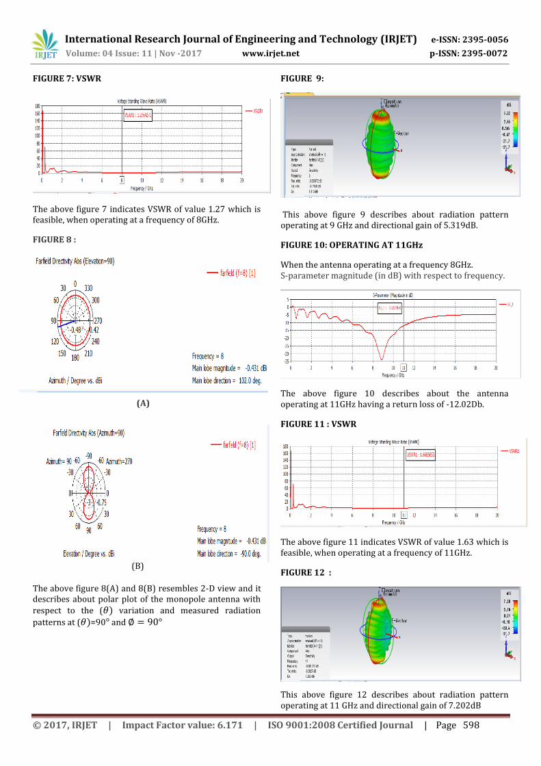
FIGURE 7: VSWR
The above figure 7 indicates VSWR of value 1.27 which is feasible, when operating at a frequency of 8GHz.
FIGURE 8 :
(A)
(B)
The above figure 8(A) and 8(B) resembles 2-D view and it describes about polar plot of the monopole antenna with
respect to the ( variation and measured radiation
patterns at ( =90 and
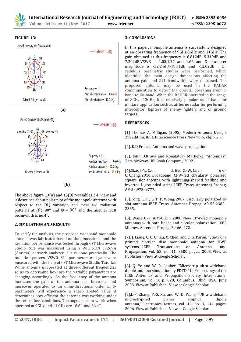
FIGURE 9:
This above figure 9 describes about radiation pattern operating at 9 GHz and directional gain of 5.319dB.
FIGURE 10: OPERATING AT 11GHz
When the antenna operating at a frequency 8GHz. S-parameter magnitude (in dB) with respect to frequency.
The above figure 10 describes about the antenna operating at 11GHz having a return loss of -12.02Db.
FIGURE 11 : VSWR
The above figure 11 indicates VSWR of value 1.63 which is feasible, when operating at a frequency of 11GHz.
FIGURE 12 :
This above figure 12 describes about radiation pattern operating at 11 GHz and directional gain of 7.202dB
International Research Journal of Engineering and Technology (IRJET) e-ISSN: 2395-0056
Volume: 04 Issue: 11 | Nov -2017 www.irjet.net p-ISSN: 2395-0072
© 2017, IRJET | Impact Factor value: 6.171 | ISO 9001:2008 Certified Journal | Page 599
FIGURE 13:
(a)
The above figure 13(A) and 13(B) resembles 2-D view and it describes about polar plot of the monopole antenna with
respect to the ( variation and measured radiation
patterns at ( =90 and and the angular 3dB
beamwidth is 66.4 .
2. SIMULATION AND RESULTS To verify the analysis, the proposed wideband monopole antenna was fabricated based on the dimensions and the radiation performance was tested through CST Microwave Studio. S11 was measured using a WILTRON 37269A (Anritsu) network analyzer if it is done practically. The radiation pattern, VSWR ,S11 parameters and gain were measured with the help of CST Microwave Studio Tutorial. While antenna is operated at three different frequencies so as to determine how are the variable parameters are changing accordingly. As the frequency of the antenna increases the gain of the antenna also increases and moreover operated as an omni-directional antenna. S-parameters will experience a sharp abated value it determines how efficient the antenna was working under the return loss conditions. The angular beam width when
operated at 9GHz and 11 GHz are 18.6 and 66.4 .
3. CONCLUSIONS In this paper, monopole antenna is successfully designed at an operating frequency of 9GHz,8GHz and 11GHz. The gain obtained at this frequency is 6.812dB, 5.319dB and 7.202dB,VSWR is 1.05,1.27 and 1.66 and S-parameter magnitude is -32.24dB,-18.31dB and -12.02dB . On sedulous parametric studies were performed, which identified the main design dimensions affecting the antenna gain and S11 bandwidth, were discussed. The proposed antenna may be used in the RADAR communication to detect the objects, operating from c-band to Ku-band. When the RADAR operated in the range of 8GHz -12GHz, it is relatively popular radar band for military application such as airborne radar for performing interceptor, fighters of enemy fighters and of ground targets.
REFERENCES [1] Thomas A. Milligan, (2005) Modern Antenna Design, 2th edition, IEEE Interscience Press New York, chpp. 2, 6. [2]. K.D.Prasad, Antenna and wave propagation. [3]. John D.Kraus and Ronalatory Marhefka, "Antennas", Tata McGraw-Hill Book Company, 2002. [4].Size, J.-Y., C.-I. G. Hsu, Z.-W. Chen, & C.-C. Chang. 2010. Broadband CPW-fed circularly polarized square slot antenna with lightening-shaped feedline and inverted-L grounded strips. IEEE Trans. Antennas Propag. AP-58:973–9777. [5].Tong, K. F., & T. P. Wong. 2007. Circularly polarized U-slot antenna. IEEE Trans. Antennas Propag. AP-55:2382–2385. [6]. Wang, C.-J., & Y.-C. Lin. 2008. New CPW-fed monopole antennas with both linear and circular polarization. IEEE Microw. Antennas Propag. 2:466–472. [7]. J. Liang, C. C. Chiau, X. Chen, and C. G. Parini, “Study of a printed circular disc monopole antenna for UWB systems,” IEEE Transactions on Antennas and Propagation, vol. 53, no. 11, 3500 pages, 2005. View at Publisher · View at Google Scholar. [8]. Q. Ye and W. R. Lauber, “Microstrip ultra-wideband dipole antenna simulation by FDTD,” in Proceedings of the IEEE Antennas and Propagation Society International Symposium, vol. 3, p. 620, Columbus, Ohio, USA, June 2003. View at Publisher · View at Google Scholar. [9].J.-P. Zhang, Y.-S. Xu, and W.-D. Wang, “Ultra-wideband microstrip-fed planar elliptical dipole antenna,” Electronics Letters, vol. 42, no. 3, 144 pages, 2006. View at Publisher · View at Google Scholar.
(b)

International Research Journal of Engineering and Technology (IRJET) e-ISSN: 2395-0056
Volume: 04 Issue: 11 | Nov -2017 www.irjet.net p-ISSN: 2395-0072
© 2017, IRJET | Impact Factor value: 6.171 | ISO 9001:2008 Certified Journal | Page 600
[10]. K. C. L. Chan, Y. Huang, and X. Zhu, “A planar elliptical monopole antenna for UWB applications,” in Proceedings of the IEEE/ACES International Conference on Wireless Communications and Applied Computational Electromagnetics, p. 182, Honolulu, Hawaii, USA, April 2005. View at Publisher · View at Google Scholar. [11]. C.-Y. Huang and W.-C. Hsia, “Planar elliptical antenna for ultra-wideband communications,” Electronics Letters, vol. 41, no. 6, 296 pages, 2005. View at Publisher · View at Google Scholar. [12]. K. P. Ray and Y. Ranga, “Ultra-wideband printed modified triangular monopole antenna,” Electronics Letters, vol. 42, no. 19, 1081 pages, 2006. View at Publisher · View at Google Scholar. [13].K. P. Ray, Y. Ranga, and P. Gabhale, “Printed square monopole antenna with semicircular base for ultra-wide bandwidth,” Electronics Letters, vol. 43, no. 5, 263 pages, 2007. View at Publisher · View at Google Scholar


![Design and Analysis of Printed Dipole Slot Antenna for · PDF file · 2014-06-21Design and Analysis of Printed Dipole Slot Antenna ... a monopole antenna [3] ... A dual band printed](https://img.pdfslide.us/doc/110x75/5aa262cf7f8b9ada698cd39d/design-and-analysis-of-printed-dipole-slot-antenna-for-2014-06-21design-and.jpg)