Embed Size (px)
Citation preview
ULTRA PRECISION MACHINING DISTURBANCE FREQUENCY EXTRACTION FROM FINISHED SURFACE
METROLOGY
Paula A. Meyer1, Stephen C. Veldhuis1, and Mohamed A. Elbestawi1 1Department of Mechanical Engineering
McMaster Manufacturing Research Institute (MMRI) McMaster University
Hamilton, Ontario, Canada.
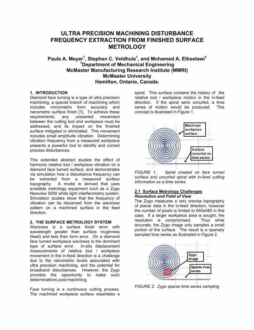
1. INTRODUCTION Diamond face turning is a type of ultra precision machining, a special branch of machining which includes micrometric form accuracy and nanometric surface finish [1]. To achieve these requirements, any unwanted movement between the cutting tool and workpiece must be addressed, and its impact on the finished surface mitigated or eliminated. This movement includes small amplitude vibration. Determining vibration frequency from a measured workpiece presents a powerful tool to identify and correct process disturbances. This extended abstract studies the effect of harmonic relative tool / workpiece vibration on a diamond face turned surface, and demonstrates via simulation how a disturbance frequency can be extracted from a measured surface topography. A model is derived that uses available metrology equipment such as a Zygo Newview 5000 white light interferometry system. Simulation studies show that the frequency of vibration can be discerned from the waviness pattern on a machined surface in the feed direction. 2. THE SURFACE METROLOGY SYSTEM Waviness is a surface finish error with wavelength greater than surface roughness (feed) and less than form error. On a diamond face turned workpiece waviness is the dominant type of surface error. In-situ displacement measurements of relative tool / workpiece movement in the in-feed direction is a challenge due to the nanometric levels associated with ultra precision machining, and the potential for broadband disturbances. However, the Zygo provides the opportunity to make such determinations post-machining. Face turning is a continuous cutting process. The machined workpiece surface resembles a
spiral. This surface contains the history of the relative tool / workpiece motion in the in-feed direction. If the spiral were uncurled, a time series of motion would be produced. This concept is illustrated in Figure 1.
FIGURE 1. Spiral created on face turned surface and uncurled spiral with in-feed cutting information as a time series. 2.1 Surface Metrology Challenges Resolution and Field of View The Zygo measures a very precise topography of planar data in the in-feed direction, however the number of pixels is limited to 640x480 in this case. If a larger workpiece area is sought, the resolution is compromised. Thus while accurate, the Zygo image only samples a small portion of the surface. The result is a sparsely sampled time series as illustrated in Figure 2.
FIGURE 2. Zygo sparse time series sampling

With respect to the Zygo image size, a 6061 aluminum workpiece with 100 mm outer diameter is considered. For finish turning conditions, a spindle speed of 1000 RPM and feed rate of 2 μm/rev is employed. According to [2] with respect to interferometric microscopy, the shortest wavelength is measurable with 5 pixels. In the feed direction, the shortest expected wavelength is the feed at 2 μm. Thus the largest recommended resolution is 0.4 μm. The most appropriate available Zygo zoom for these requirements is 800 times, with resolution of 0.28 μm. The resulting image size is 180 μm by 140 μm. If the y-axis is the feed direction, then the maximum observable feed direction wavelength is 140 μm with this particular zoom and resolution. Constantly Changing Cutting Speed and Time Interval Further complications arise from the fact that the feed rate and spindle speed used are constant. This means that the effective cutting speed changes constantly during face turning. A Zygo image has fixed spatial sampling, and thus the corresponding time interval in the sparsely sampled time series is not constant. 3. DERIVATION OF EQUATIONS Relative tool / workpiece motion in the in-feed direction, z(t), is assumed to be harmonic with disturbance frequency ωd and constant amplitude zamp as described in equation (1). By superposition, if other harmonic motion exists, then the values can be summed together.
)sin()( tztz damp ω= (1) 3.1 Derivation to Accommodate Surface Metrology System Re-expressing equation (1) in polar coordinates in the feed direction addresses some of the issues identified in the previous section like a sparsely sampled time series, and a variable time interval. In equation (2) angle θ is the rotation of the workpiece, and is a function of time and spindle speed.
⎟⎠⎞
⎜⎝⎛=
Nzz damp π
θωθ
260
sin)( (2)
Next consider a workpiece that is discretized radially as shown in Figure 3, where each spoke is called θ1p. Subsequent rotations add 2π radians to each θ1 value. For any given spoke
p, equation (3) applies, where m is an integer representing the number of rotations.
( )⎥⎦⎤
⎢⎣⎡ += p
damppm m
Nzz 12
260
sin)( θππω
θ (3)
This derivation is similar to that found in [3], [4], [5] and [6]. Details on the tool geometry are not included in this simulation.
θ1b
θ1c
ZygoMeasurement Location
FIGURE 3. Radial discretization of workpiece with Zygo measurement location noted. Equation (3) is in the classical configuration of an angular velocity and phase angle. Here angular velocity is in radians per rotation as expressed in equation (4), and phase angle is in radians as expressed in equation (5).
⎟⎠⎞
⎜⎝⎛=Ωrevolutionradians
Ndω60 (4)
( )radiansN
p pd
πθω
φ2
60)( 1= (5)
Equation (4) indicates that regardless of the spoke in question, θ1p, for constant spindle speed and disturbance frequency, the spatial frequency in the feed direction is always the same. Thus, if a spatial Fast Fourier Transform (FFT) is performed on a Zygo image of feed lines, then all feed lines should yield the same magnitude information. However, due to the cyclical nature of the sine wave, various disturbance frequencies for a given spindle speed will yield the same spatial frequency magnitude results. However, from equation (5) it is also evident that the phase angle for each spoke is unique. From equation (5) an expression to find the unique disturbance frequency for a dominant

spatial waviness pattern can be found from a Zygo image. Subscripts a and b in equation (6) represent spoke indices for closely spaced feed lines in the Zygo image.
ab
abd N 11
11
260
φφπθθ
ω−
−= (6)
4. SIMULATION AND RESULTS A Zygo measured surface is simulated in Matlab with a known disturbance frequency ωd and amplitude zamp. The disturbance frequency used is from an experimental data set. Then from the simulated surface, without knowing it a priori, the disturbance frequency is extracted via equation (6). Following this a comparison is made between the actual and estimated disturbance frequency. 4.1 Experimental Data Used in Simulation In-situ vibration measurements have been made on an ASG 2500 diamond turning machine using a Kistler 8702B50 accelerometer and a 8702B25 accelerometer at the tool and spindle locations respectively. Signals are analogue anti-alias filtered, and sampled synchronously with a NI PCI-6023E. In Matlab the signals are differenced for relative acceleration, and an FFT is then performed to see the dominant disturbance frequencies. For the cutting conditions described in Section 2, the power spectrum in Figure 4 is produced. A dominant observed disturbance frequency of 4928.2 Hz is used in simulation.
0 2000 4000 6000 80000
500
1000
1500
Power spectrum (RMS), Hanning windowed, number of averages = 12,
frequency increment = 0.1069 Hz
Pow
er S
pect
rum
g2
Frequency (Hz)
4928.2 Hz
FIGURE 4. Power spectrum of relative tool / workpiece acceleration on ASG 250 For simulation, the workpiece surface is assumed to be measured at a radius of 40 mm with feed direction along the y-axis, and the cutting direction along the x-axis. Using the
orientation shown in Figure 3, the median image θ1 is
23π radians.
4.2 Simulation Results With the dominant disturbance frequency of 4982.2 Hz observed in Figure 4, the resulting wavelength in the feed direction is 29.43 μm and observable in the 800 times zoom field of view according to [2]. The amplitude zamp used in simulation is 1 nm. The simulated Zygo image is shown in Figure 5. The x and y axis values are the workpiece coordinates which have their origin at the workpiece center.
FIGURE 5. Simulated Zygo image with disturbance frequency of 4928.2 Hz. In Figure 6, five equally spaced feed lines are plotted. Here the phase angle shift is observable. For illustration purposes, the feed line spacing that is depicted in Figure 6 is larger than the image θ1 resolution of 0.0016 degrees, and is still within the bounds of the Zygo image.
39.96 39.97 39.98 39.99 40-10
-5
0
5
x 10-7
In-feed displacement versus radius for 5 feed lines with
radial spacing of 0.16 degrees
Radius (mm)
z (m
m)
FIGURE 6. Five equally spaced feed lines demonstrating change in phase angle.


![Traceability on Machine Tool Metrology: A Review...Traceable measurements on machine tools [6]. 2.1. Monitoring machine performance Machine geometry may change during machining operation](https://img.pdfslide.us/doc/110x75/60046b51db50ba3d6f649a60/traceability-on-machine-tool-metrology-a-review-traceable-measurements-on-machine.jpg)